Air Module System - Spektrum · Spektrum Air Module Alternate Languages ITALIAN: Per la versione...
32
Air Module System
Transcript of Air Module System - Spektrum · Spektrum Air Module Alternate Languages ITALIAN: Per la versione...
Air Module System
Spektrum Air Module�
Alternate Languages ...................................................................................3Introduction................................................................................................3Features and Benefits .................................................................................4Specifications.............................................................................................4
DSM Air modules. ............................................................................4Important Module Information ...................................................................5Installation .................................................................................................6
Preparing the Transmitter ..................................................................6Installing the Spektrum Antenna and Module ...................................7Futaba MZ Modules Only .................................................................9
Installing the Receiver ..............................................................................11Installing the AR7000 ......................................................................11Installing the AR9000 ......................................................................13Installing the AR6100 ......................................................................16
Binding ....................................................................................................17How to Bind ....................................................................................17
Fail-Safe Functions ..................................................................................20SmartSafe........................................................................................20Receiver Power Only .......................................................................20After Connection .............................................................................20
Preset Fail-Safe ........................................................................................21Receiver Power Only .......................................................................21After Connection .............................................................................21Programming SmartSafe(All Spektrum Aircraft Receivers) ..............21Programming Preset Fail-safe(AR 9000 Spektrum Receivers Only) 21SmartSafe Fail-safe Setup ...............................................................21
Table of Contents
Futaba FZ Module Special Instructions ....................................................22FZ Spektrum Module Instructions ...................................................22Channel Assignment .......................................................................24Default Channel Assignment for CCPM helicopters .......................24Default Channel Assignment for Sailplanes ....................................24
How to Range Test the Spektrum Module System ....................................25Range Testing the Module System ..................................................25
Flight Log—Optional for the AR9000 ......................................................26Using the Flight Log .......................................................................26
FCC Information ......................................................................................27Warranty and Service Information ............................................................28
Warning ..........................................................................................28Warranty Period ..............................................................................28Limited Warranty .............................................................................28Damage Limits ................................................................................29Safety Precautions ..........................................................................29Questions, Assistance, and Repairs ................................................29Inspection or Repairs ......................................................................29Warranty Inspection and Repairs.....................................................30Non-Warranty Repairs .....................................................................30Safety, Precautions, and Warnings ..................................................31
Spektrum Air Module �
Alternate Languages
ITALIAN: Per la versione italiana di questo manuale vi preghiamo di visitare il sito www.spektrumrc.comFRENCH: Pour consulter ce manuel en français, visiter le site www.spektrumrc.comGERMAN: Zur Ansicht der Bedienunsanleitung in den Deutsch besuchen Sie bitte www.spektrumrc.comSPANISH: Para ver este manual en Español entra en www.spektrumrc.com
Introduction
Spektrum’s Aircraft Module systems offer the ultimate in radio link security. Most popular brands of module-based aircraft radios can be converted to Spektrum™ 2.4GHz DSM® technology by simply plugging in the appropriate Spektrum module and installing the included antenna. No longer will you have to wait for an open frequency, or struggle with interference caused from noisy motors, ignition systems or other RF noise-generating sources. Spektrum’s module systems utilize proprietary DSM2™ second generation Digital Spread Spectrum Modulation technology, providing an impenetrable radio link.Operating within the ultra high frequency 2.4GHz worldwide ISM band, each module is programmed with its own unique serial code called GUID (Globally Unique Identification code). Once a receiver is programmed to a specific module (called binding), the receiver will only recognize and respond to that module ignoring signals from any other sources.Spektrum’s module systems are compatible with all DSM2 receivers including the AR7000 and AR9000 full-range receivers and the 6100 parkflyer receiver.
Note: The Module system is not compatible with the AR6000 first generation DSM® receivers.
Important: When using the Module system with the 6100 parkflyer receivers, it’s imperative that this receiver only be flown in parkflyer type models. This includes all types of small electric airplanes and mini and micro helicopters. Do not fly the AR6100 receiver in large gas, glow or large electric aircraft as loss of control at extended range due to signal blocking issues can occur.
Spektrum Air Module�
• Converts most popular brands of module based radio systems to Spektrum’s DSM2 2.4GHz technology• No more waiting for an open frequency• Eliminates the possibility of interference from an unintentional turn-on• Bulletproof interference rejection of all outside RF sources like cell phones, WiFi systems, other transmitters, etc.• Impervious to model-generated RF interference (like noisy electric motors, metal-to-metal noise or ignition systems)• Operates on the 2.4GHz ISM band allowing international use• No maintenance or tuning ever required• Fail-safe system drives the throttle to preset position at loss of signal (see fail-safe options on page 20)• Legal at all AMA flying field and events
Features and Benefits
Specifications
DSM Air Modules
2.400–2.483GHzSpectral capacity - 40 SystemsType - Direct Sequence Spread SpectrumDSSS coding gain - 18dBDiversity - MultiLink: Path, Time and FrequencyModule current - 200mAReceiver current - 70mAReceiver voltage range - 3.5–9V DCServo channels - 9 JR, 8 FutabaServo channel resolution - 1024 with 4X oversampling
Spektrum Air Module �
• Be sure the transmitter is in PPM modulation mode. If necessary, refer to the instructions included with your radio system for details on how to program your transmitter to PPM modulation. Note: The Spektrum module system will not operate in PCM modulation mode.
• Never power up the module unless the antenna is connected. Doing so can overload the module’s electronics causing damage to the module.
• Before operating, the receiver must be bound to the module (see page 17 for binding instructions). Binding is the process of teaching the receiver the transmitter’s specific GUID (globally unique identifier) code. Binding also sets the fail-safe positions. It’s also recommended that the system be rebound again after radio setup to establish and confirm the desired fail-safe positions.
• Before each flying session, it’s imperative that you do a range check (see page 25 for details) to confirm that the system is working properly.
• When using the Module system with the 6100 parkflyer receiver, it’s imperative that this receiver only be flown in parkflyer type models. This includes all types of small electric airplane and mini and micro helicopters. DO NOT fly the AR6100 receiver in large gas or glow aircraft as loss of control at extended range due to signal blocking issues can occur.
• The Module system features DSM2 technology and is compatible will all DSM2 compatible receivers. The Module system is not compatible with the AR6000 DSM first generation receiver.
Important Module Information
Spektrum Air Module�
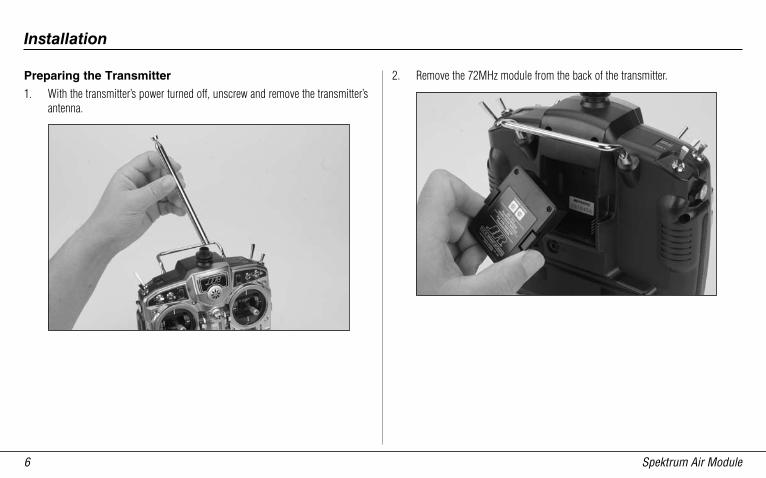
Preparing the Transmitter
1. With the transmitter’s power turned off, unscrew and remove the transmitter’s antenna.
Installation
2. Remove the 72MHz module from the back of the transmitter.
Spektrum Air Module �
Installation
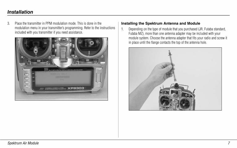
3. Place the transmitter in PPM modulation mode. This is done in the modulation menu in your transmitter’s programming. Refer to the instructions included with you transmitter if you need assistance.
Installing the Spektrum Antenna and Module
1. Depending on the type of module that you purchased (JR, Futaba standard, Futaba MZ), more than one antenna adapter may be included with your module system. Choose the antenna adapter that fits your radio and screw it in place until the flange contacts the top of the antenna hole.
Spektrum Air Module�
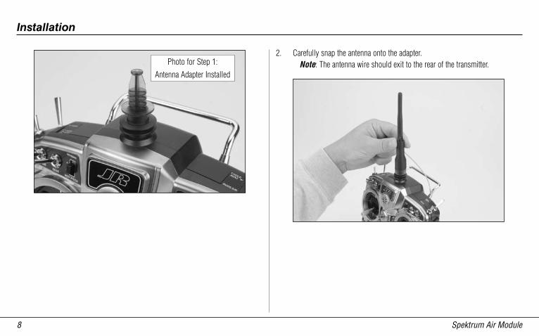
2. Carefully snap the antenna onto the adapter.Note: The antenna wire should exit to the rear of the transmitter.
Installation
Photo for Step 1:Antenna Adapter Installed
Spektrum Air Module �
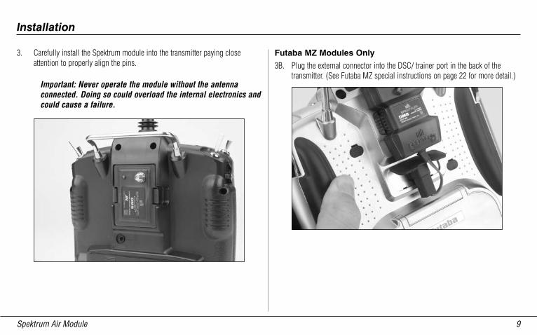
3. Carefully install the Spektrum module into the transmitter paying close attention to properly align the pins.
Important: Never operate the module without the antenna connected. Doing so could overload the internal electronics and could cause a failure.
Futaba MZ Modules Only
3B. Plug the external connector into the DSC/ trainer port in the back of the transmitter. (See Futaba MZ special instructions on page 22 for more detail.)
Installation
Spektrum Air Module10
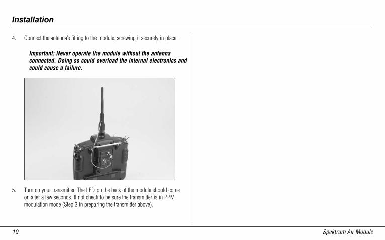
4. Connect the antenna’s fitting to the module, screwing it securely in place.
Important: Never operate the module without the antenna connected. Doing so could overload the internal electronics and could cause a failure.
5. Turn on your transmitter. The LED on the back of the module should come on after a few seconds. If not check to be sure the transmitter is in PPM modulation mode (Step 3 in preparing the transmitter above).
Installation
Spektrum Air Module 11
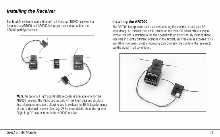
The Module system is compatible with all Spektrum DSM2 receivers that includes the AR7000 and AR9000 full-range receivers as well as the AR6100 parkflyer receiver.
Note: An optional Flight Log RF data recorder is available only for the AR9000 receiver. The Flight Log records RF link flight data and displays this information onscreen, allowing you to evaluate the RF link performance of each individual receiver. See page 26 for more details about the optional Flight Log RF data recorder fo the AR9000 receiver.
Installing the Receiver
Installing the AR7000
The AR7000 incorporates dual receivers, offering the security of dual path RF redundancy. An internal receiver is located on the main PC board, while a second remote receiver is attached to the main board with an extension. By locating these receivers in slightly different locations in the aircraft, each receiver is exposed to its own RF environment, greatly improving path diversity (the ability of the receiver to see the signal in all conditions).
Spektrum Air Module1�
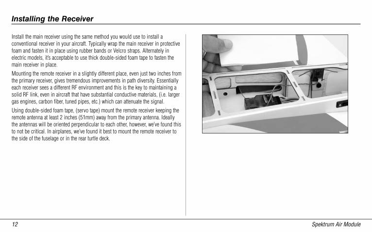
Install the main receiver using the same method you would use to install a conventional receiver in your aircraft. Typically wrap the main receiver in protective foam and fasten it in place using rubber bands or Velcro straps. Alternately in electric models, it’s acceptable to use thick double-sided foam tape to fasten the main receiver in place.Mounting the remote receiver in a slightly different place, even just two inches from the primary receiver, gives tremendous improvements in path diversity. Essentially each receiver sees a different RF environment and this is the key to maintaining a solid RF link, even in aircraft that have substantial conductive materials, (i.e. larger gas engines, carbon fiber, tuned pipes, etc.) which can attenuate the signal.Using double-sided foam tape, (servo tape) mount the remote receiver keeping the remote antenna at least 2 inches (51mm) away from the primary antenna. Ideally the antennas will be oriented perpendicular to each other, however, we’ve found this to not be critical. In airplanes, we’ve found it best to mount the remote receiver to the side of the fuselage or in the rear turtle deck.
Installing the Receiver
Spektrum Air Module 1�
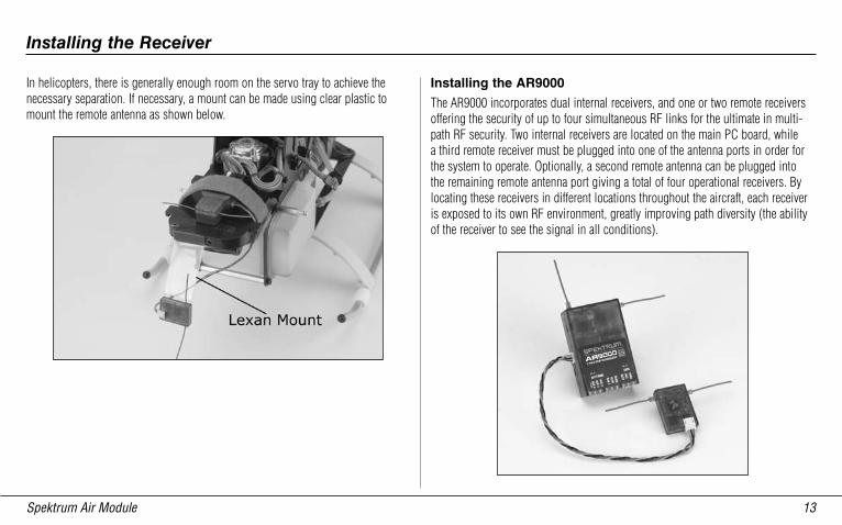
In helicopters, there is generally enough room on the servo tray to achieve the necessary separation. If necessary, a mount can be made using clear plastic to mount the remote antenna as shown below.
Installing the AR9000
The AR9000 incorporates dual internal receivers, and one or two remote receivers offering the security of up to four simultaneous RF links for the ultimate in multi-path RF security. Two internal receivers are located on the main PC board, while a third remote receiver must be plugged into one of the antenna ports in order for the system to operate. Optionally, a second remote antenna can be plugged into the remaining remote antenna port giving a total of four operational receivers. By locating these receivers in different locations throughout the aircraft, each receiver is exposed to its own RF environment, greatly improving path diversity (the ability of the receiver to see the signal in all conditions).
Installing the Receiver
Spektrum Air Module1�
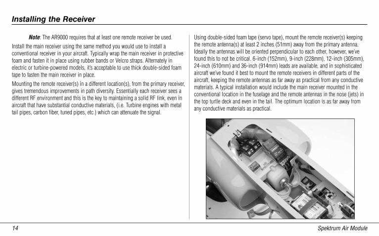
Note: The AR9000 requires that at least one remote receiver be used.Install the main receiver using the same method you would use to install a conventional receiver in your aircraft. Typically wrap the main receiver in protective foam and fasten it in place using rubber bands or Velcro straps. Alternately in electric or turbine-powered models, it’s acceptable to use thick double-sided foam tape to fasten the main receiver in place.Mounting the remote receiver(s) in a different location(s), from the primary receiver, gives tremendous improvements in path diversity. Essentially each receiver sees a different RF environment and this is the key to maintaining a solid RF link, even in aircraft that have substantial conductive materials, (i.e. Turbine engines with metal tail pipes, carbon fiber, tuned pipes, etc.) which can attenuate the signal.
Using double-sided foam tape (servo tape), mount the remote receiver(s) keeping the remote antenna(s) at least 2 inches (51mm) away from the primary antenna. Ideally the antennas will be oriented perpendicular to each other, however, we’ve found this to not be critical. 6-inch (152mm), 9-inch (228mm), 12-inch (305mm), 24-inch (610mm) and 36-inch (914mm) leads are available, and in sophisticated aircraft we’ve found it best to mount the remote receivers in different parts of the aircraft, keeping the remote antennas as far away as practical from any conductive materials. A typical installation would include the main receiver mounted in the conventional location in the fuselage and the remote antennas in the nose (jets) in the top turtle deck and even in the tail. The optimum location is as far away from any conductive materials as practical.
Installing the Receiver
Spektrum Air Module 1�
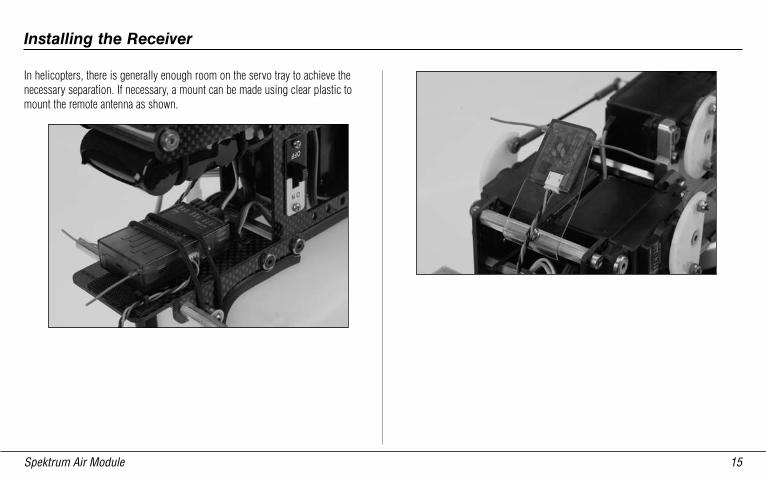
In helicopters, there is generally enough room on the servo tray to achieve the necessary separation. If necessary, a mount can be made using clear plastic to mount the remote antenna as shown.
Installing the Receiver
Spektrum Air Module1�
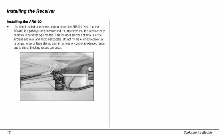
Installing the AR6100
• Use double-sided tape (servo tape) to mount the AR6100. Note that the AR6100 is a parkflyer-only receiver and it’s imperative that this receiver only be flown in parkflyer type models. This includes all types of small electric airplane and mini and micro helicopters. Do not fly the AR6100 receiver in large gas, glow or large electric aircraft, as loss of control at extended range due to signal blocking issues can occur.
Installing the Receiver
Spektrum Air Module 1�
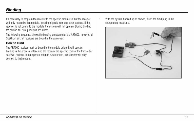
It’s necessary to program the receiver to the specific module so that the receiver will only recognize that module, ignoring signals from any other sources. If the receiver is not bound to the module, the system will not operate. During binding the servo’s fail-safe positions are stored.The following sequence shows the binding procedure for the AR7000, however, all Spektrum aircraft receivers are bound in the same way.How to Bind
The AR7000 receiver must be bound to the module before it will operate. Binding is the process of teaching the receiver the specific code of the transmitter so it will connect to that specific module. Once bound, the receiver will only connect to that module.
1. With the system hooked up as shown, insert the bind plug in the charge plug receptacle.
Binding
Spektrum Air Module1�
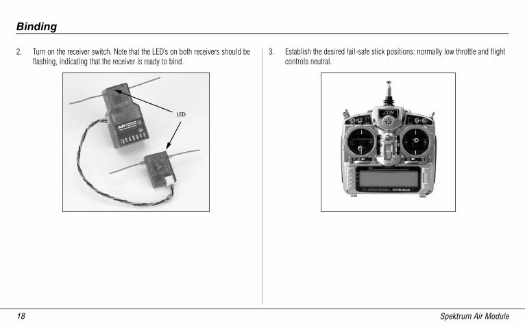
2. Turn on the receiver switch. Note that the LED’s on both receivers should be flashing, indicating that the receiver is ready to bind.
3. Establish the desired fail-safe stick positions: normally low throttle and flight controls neutral.
Binding
Spektrum Air Module 1�
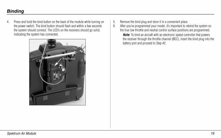
4. Press and hold the bind button on the back of the module while turning on the power switch. The bind button should flash and within a few seconds the system should connect. The LED’s on the receivers should go solid, indicating the system has connected.
5. Remove the bind plug and store it in a convenient place.6. After you’ve programmed your model, it’s important to rebind the system so
the true low throttle and neutral control surface positions are programmed.Note: To bind an aircraft with an electronic speed controller that powers the receiver through the throttle channel (BEC), insert the bind plug into the battery port and proceed to Step #2.
Binding
Spektrum Air Module�0
All of Spektrum’s aircraft receivers feature a unique SmartSafe fail-safe system, while the AR 9000 features two types of fail-safe: SmartSafe and preset fail-safe.SmartSafe
This type of fail-safe is especially ideal for most types of electric aircraft and is also recommended for most types of gas- and glow-powered airplanes and helicopters. Here’s how SmartSafe works.Receiver Power Only
When the receiver only is turned on (no transmitter signal is present), all servos except for the throttle are driven to their preset fail-safe positions, normally control surfaces at neutral and the landing gear down. These fail-safe positions are stored in the receiver during binding. At this time the throttle channel has no output, to avoid operating or arming the electronic speed control. In glow-powered models, the throttle servo has no input so it remains in its current position.
After Connection
When the transmitter is turned on and after the receiver connects to the transmitter, normal control of all channels occurs. After the system makes a connection, if loss of signal occurs SmartSafe drives the throttle servo only to its preset fail-safe position (low throttle) that was set during binding. All other channels hold their last position. When the signal is regained, the system immediately (less than 4 ms) regains control.
Fail-Safe Functions
Spektrum Air Module �1
Preset fail-safe is ideal for sailplanes and is preferred by some modelers for their glow- and gas-powered aircraft.Receiver Power Only
When the receiver only is turned on (no transmitter signal is present) all servos except for the throttle are driven to their preset fail-safe positions, normally control surfaces at neutral and the landing gear down. These fail-safe positions are stored in the receiver during binding. At this time the throttle channel has no output, to avoid operating or arming the electronic speed control. In glow-powered models, the throttle servo has no input so it remains in its current position.After Connection
When the transmitter is turned on and after the receiver connects to the transmitter, normal control of all channels occurs. After the system makes a connection, if loss of signal occurs preset fail-safe drives all servos to their preset fail-safe positions. For sailplanes it’s recommended that the spoilers/ flaps deploy to de-thermalize the aircraft, preventing a flyaway. Some powered modelers prefer to use this fail-safe system to program a slight turn and low throttle to prevent their aircraft from flying away. When the signal is regained, the system immediately (less than 4 ms) regains control.
Programming SmartSafe (All Spektrum Aircraft Receivers)
During the binding process (see page 17), the bind plug is left in throughout the process and is removed only after the receiver connects to the transmitter. After the connection is made, confirmed by operating the servos, the bind plug can be removed. The receiver is now programmed for SmartSafe.Programming Preset Fail-safe (AR 9000 SPM Receivers Only)
During the binding process the bind plug is inserted in the bind port or in the charge jack (as shown on page 17), then the receiver is powered up. The LED’s in each receiver should blink, indicating that the receiver is in bind mode. Now before binding the receiver to the transmitter and with the receiver in bind mode, remove the bind plug. The LED’s will still be blinking. With the control sticks and switches in the desired fail-safe positions, bind the transmitter to the receiver by pressing and holding the bind buttons on the back of the transmitter/module and turning on the transmitter. The system should connect in less than 15 seconds. The receiver is now programmed for preset fail-safe.
Note: Fail-safe positions are stored via the stick and switch positions on the transmitter during binding.
Preset Fail-Safe
Spektrum Air Module��
Futaba’s 12MZ and 14MZ transmitters utilize a unique module design. While most 72MHz modules contain the complete RF electronics section that embeds the encoded PPM signal from the transmitter into the carrier signal, Futaba MZ modules operate using a different method. With the 12 and 14MZ transmitters, the PPM signal is actually applied to the carrier signal within the transmitter, not in the module. Note that the MZ 2.4GHz Spektrum module has an external connector attached that must be plugged into the DSC port in the back of the transmitter. The Spektrum module then captures the PPM stream through this DSC port.
Note: During operation the Futaba Logo at the top of the transmitter will flash. This is normal and occurs because the transmitter recognizes the module in use is not a Futaba brand module.
Note: Futaba’s MZ transmitter outputs eight-PPM channels. Consequently the MZ module is an eight-channel system.
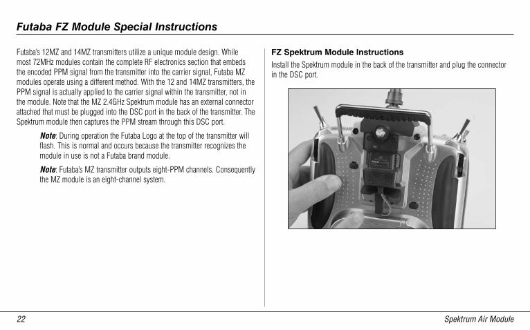
FZ Spektrum Module Instructions
Install the Spektrum module in the back of the transmitter and plug the connector in the DSC port.
Futaba FZ Module Special Instructions
Spektrum Air Module ��
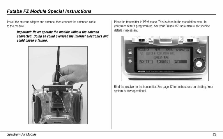
Install the antenna adapter and antenna, then connect the antenna’s cable to the module.
Important: Never operate the module without the antenna connected. Doing so could overload the internal electronics and could cause a failure.
Place the transmitter in PPM mode. This is done in the modulation menu in your transmitter’s programming. See your Futaba MZ radio manual for specific details if necessary.
Bind the receiver to the transmitter. See page 17 for instructions on binding. Your system is now operational.
Futaba FZ Module Special Instructions
Spektrum Air Module��
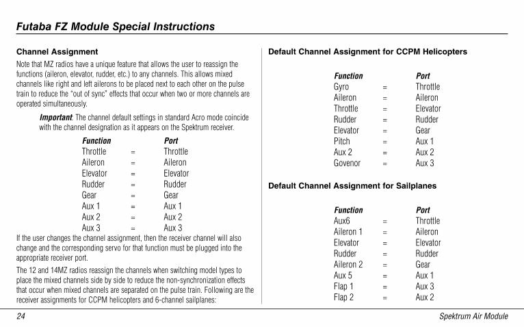
Channel Assignment
Note that MZ radios have a unique feature that allows the user to reassign the functions (aileron, elevator, rudder, etc.) to any channels. This allows mixed channels like right and left ailerons to be placed next to each other on the pulse train to reduce the “out of sync” effects that occur when two or more channels are operated simultaneously.
Important: The channel default settings in standard Acro mode coincide with the channel designation as it appears on the Spektrum receiver.
Function PortThrottle = ThrottleAileron = AileronElevator = ElevatorRudder = RudderGear = GearAux 1 = Aux 1Aux 2 = Aux 2Aux 3 = Aux 3
If the user changes the channel assignment, then the receiver channel will also change and the corresponding servo for that function must be plugged into the appropriate receiver port.The 12 and 14MZ radios reassign the channels when switching model types to place the mixed channels side by side to reduce the non-synchronization effects that occur when mixed channels are separated on the pulse train. Following are the receiver assignments for CCPM helicopters and 6-channel sailplanes:
Default Channel Assignment for CCPM Helicopters
Function PortGyro = ThrottleAileron = AileronThrottle = ElevatorRudder = RudderElevator = GearPitch = Aux 1Aux 2 = Aux 2Govenor = Aux 3
Default Channel Assignment for Sailplanes
Function PortAux6 = ThrottleAileron 1 = AileronElevator = ElevatorRudder = RudderAileron 2 = GearAux 5 = Aux 1Flap 1 = Aux 3Flap 2 = Aux 2
Futaba FZ Module Special Instructions
Spektrum Air Module ��
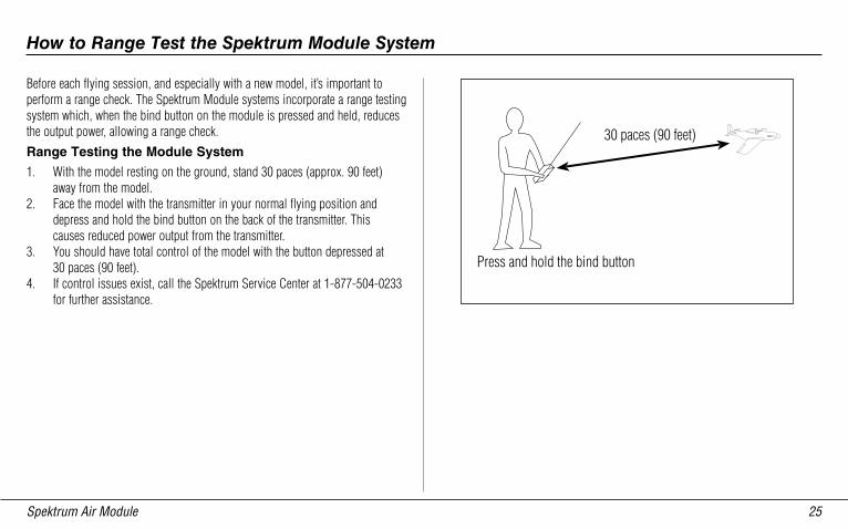
Before each flying session, and especially with a new model, it’s important to perform a range check. The Spektrum Module systems incorporate a range testing system which, when the bind button on the module is pressed and held, reduces the output power, allowing a range check.Range Testing the Module System
1. With the model resting on the ground, stand 30 paces (approx. 90 feet) away from the model.
2. Face the model with the transmitter in your normal flying position and depress and hold the bind button on the back of the transmitter. This causes reduced power output from the transmitter.
3. You should have total control of the model with the button depressed at 30 paces (90 feet).
4. If control issues exist, call the Spektrum Service Center at 1-877-504-0233 for further assistance.
How to Range Test the Spektrum Module System
Spektrum Air Module��
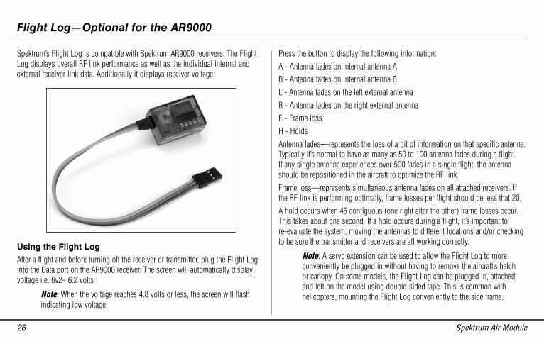
Spektrum’s Flight Log is compatible with Spektrum AR9000 receivers. The Flight Log displays overall RF link performance as well as the individual internal and external receiver link data. Additionally it displays receiver voltage.
Using the Flight Log
After a flight and before turning off the receiver or transmitter, plug the Flight Log into the Data port on the AR9000 receiver. The screen will automatically display voltage i.e. 6v2= 6.2 volts
Note: When the voltage reaches 4.8 volts or less, the screen will flash indicating low voltage.
Press the button to display the following information:A - Antenna fades on internal antenna AB - Antenna fades on internal antenna BL - Antenna fades on the left external antennaR - Antenna fades on the right external antennaF - Frame lossH - HoldsAntenna fades—represents the loss of a bit of information on that specific antenna. Typically it’s normal to have as many as 50 to 100 antenna fades during a flight. If any single antenna experiences over 500 fades in a single flight, the antenna should be repositioned in the aircraft to optimize the RF link.Frame loss—represents simultaneous antenna fades on all attached receivers. If the RF link is performing optimally, frame losses per flight should be less that 20.A hold occurs when 45 contiguous (one right after the other) frame losses occur. This takes about one second. If a hold occurs during a flight, it’s important to re-evaluate the system, moving the antennas to different locations and/or checking to be sure the transmitter and receivers are all working correctly.
Note: A servo extension can be used to allow the Flight Log to more conveniently be plugged in without having to remove the aircraft’s hatch or canopy. On some models, the Flight Log can be plugged in, attached and left on the model using double-sided tape. This is common with helicopters, mounting the Flight Log conveniently to the side frame.
Flight Log—Optional for the AR9000
Spektrum Air Module ��
FCC Information
FCC ID: BRWDAMTX10 IC: 6157A-BRWDAMTThis device complies with part 15 of the FCC rules. Operation is subject to the following two conditions: (1) This device may not cause harmful interference, and (2) this device must accept any interference received, including interference that may cause undesired operation.
Caution: Changes or modifications not expressly approved by Horizon Hobby, Inc. could void the user’s authority to operate the equipment.
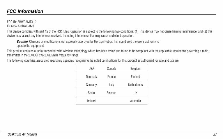
This product contains a radio transmitter with wireless technology which has been tested and found to be compliant with the applicable regulations governing a radio transmitter in the 2.400GHz to 2.4835GHz frequency range.The following countries associated regulatory agencies recognizing the noted certifications for this product as authorized for sale and use are:
USA Canada Belgium
Denmark France Finland
Germany Italy Netherlands
Spain Sweden UK
Ireland Australia
Spektrum Air Module��
Warning
An RC aircraft is not a toy! If misused, it can cause serious bodily harm and damage to property. Fly only in open areas, preferably at AMA (Academy of Model Aeronautics) approved flying sites, following all instructions included with your radio.Keep loose items that can get entangled in the propeller away from the prop, including loose clothing, or other objects such as pencils and screwdrivers. Especially keep your hands away from the propeller.
Warranty Period
Exclusive Warranty- Horizon Hobby, Inc., (Horizon) warranties that the Products purchased (the “Product”) will be free from defects in materials and workmanship for a period of 1 year from the date of purchase by the Purchaser.
Limited Warranty
(a) This warranty is limited to the original Purchaser ("Purchaser") and is not transferable. REPAIR OR REPLACEMENT AS PROVIDED UNDER THIS WARRANTY IS THE EXCLUSIVE REMEDY OF THE PURCHASER. This warranty covers only those Products purchased from an authorized Horizon dealer. Third party transactions are not covered by this warranty. Proof of purchase is required for warranty claims. Further, Horizon reserves the right to change or modify this warranty without notice and disclaims all other warranties, express or implied.(b) Limitations- HORIZON MAKES NO WARRANTY OR REPRESENTATION, EXPRESS OR IMPLIED, ABOUT NON-INFRINGEMENT, MERCHANTABILITY OR FITNESS FOR A PARTICULAR PURPOSE OF THE PRODUCT. THE PURCHASER ACKNOWLEDGES THAT THEY ALONE HAVE DETERMINED THAT THE PRODUCT WILL SUITABLY MEET THE REQUIREMENTS OF THE PURCHASER’S INTENDED USE.(c) Purchaser Remedy- Horizon's sole obligation hereunder shall be that Horizon will, at its option, (i) repair or (ii) replace, any Product determined by Horizon to be defective. In the event of a defect, these are the Purchaser's exclusive remedies. Horizon reserves the right to inspect any and all equipment involved in a warranty claim. Repair or replacement decisions are at the sole discretion of Horizon. This warranty does not cover cosmetic damage or damage due to acts of God, accident, misuse, abuse, negligence, commercial use, or modification of or to any part of the Product. This warranty does not cover damage due to improper installation, operation, maintenance, or attempted repair by anyone other than Horizon. Return of any goods by Purchaser must be approved in writing by Horizon before shipment.
Warranty and Service Information
Spektrum Air Module ��
Damage Limits
HORIZON SHALL NOT BE LIABLE FOR SPECIAL, INDIRECT OR CONSEQUENTIAL DAMAGES, LOSS OF PROFITS OR PRODUCTION OR COMMERCIAL LOSS IN ANY WAY CONNECTED WITH THE PRODUCT, WHETHER SUCH CLAIM IS BASED IN CONTRACT, WARRANTY, NEGLIGENCE, OR STRICT LIABILITY. Further, in no event shall the liability of Horizon exceed the individual price of the Product on which liability is asserted. As Horizon has no control over use, setup, final assembly, modification or misuse, no liability shall be assumed nor accepted for any resulting damage or injury. By the act of use, setup or assembly, the user accepts all resulting liability.If you as the Purchaser or user are not prepared to accept the liability associated with the use of this Product, you are advised to return this Product immediately in new and unused condition to the place of purchase.Law: These Terms are governed by Illinois law (without regard to conflict of law principals).
Safety Precautions
This is a sophisticated hobby Product and not a toy. It must be operated with caution and common sense and requires some basic mechanical ability. Failure to operate this Product in a safe and responsible manner could result in injury or damage to the Product or other property. This Product is not intended for use by children without direct adult supervision. The Product manual contains instructions for safety, operation and maintenance. It is essential to read and follow all the instructions and warnings in the manual, prior to assembly, setup or use, in order to operate correctly and avoid damage or injury.
Questions, Assistance, and Repairs
Your local hobby store and/or place of purchase cannot provide warranty support or repair. Once assembly, setup or use of the Product has been started, you must contact Horizon directly. This will enable Horizon to better answer your questions and service you in the event that you may need any assistance. For questions or assistance, please direct your email to [email protected], or call 877.504.0233 toll free to speak to a service technician.
Inspection or Repairs
If this Product needs to be inspected or repaired, please call for a Return Merchandise Authorization (RMA). Pack the Product securely using a shipping carton. Please note that original boxes may be included, but are not designed to withstand the rigors of shipping without additional protection. Ship via a carrier that provides tracking and insurance for lost or damaged parcels, as Horizon is not responsible for merchandise until it arrives and is accepted at our facility. A Service Repair Request is available at www.horizonhobby.com on the “Support” tab. If you do not have internet access, please include a letter with your complete name, street address, email address and phone number where you can be reached during business days, your RMA number, a list of the included items, method of payment for any non-warranty expenses and a brief summary of the problem. Your original sales receipt must also be included for warranty consideration. Be sure your name, address, and RMA number are clearly written on the outside of the shipping carton.
Spektrum Air Module�0
Warranty Inspection and Repairs
To receive warranty service, you must include your original sales receipt verifying the proof-of-purchase date. Provided warranty conditions have been met, your Product will be repaired or replaced free of charge. Repair or replacement decisions are at the sole discretion of Horizon Hobby.
Non-Warranty Repairs
Should your repair not be covered by warranty the repair will be completed and payment will be required without notification or estimate of the expense unless the expense exceeds 50% of the retail purchase cost. By submitting the item for repair you are agreeing to payment of the repair without notification. Repair estimates are available upon request. You must include this request with your repair. Non-warranty repair estimates will be billed a minimum of ½ hour of labor. In addition you will be billed for return freight. Please advise us of your preferred method of payment. Horizon accepts money orders and cashiers checks, as well as Visa, MasterCard, American Express, and Discover cards. If you choose to pay by credit card, please include your credit card number and expiration date. Any repair left unpaid or unclaimed after 90 days will be considered abandoned and will be disposed of accordingly. Please note: non-warranty repair is only available on electronics and model engines.Electronics and engines requiring inspection or repair should be shipped to the following address:Horizon Service Center 4105 Fieldstone Road Champaign, Illinois 61822All other Products requiring warranty inspection or repair should be shipped to the following address:Horizon Product Support 4105 Fieldstone Road Champaign, Illinois 61822Please call 877-504-0233 with any questions or concerns regarding this product or warranty.
Spektrum Air Module �1
Safety, Precautions, and Warnings
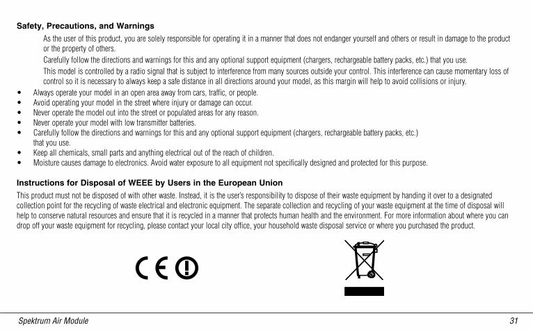
As the user of this product, you are solely responsible for operating it in a manner that does not endanger yourself and others or result in damage to the product or the property of others.Carefully follow the directions and warnings for this and any optional support equipment (chargers, rechargeable battery packs, etc.) that you use.This model is controlled by a radio signal that is subject to interference from many sources outside your control. This interference can cause momentary loss of control so it is necessary to always keep a safe distance in all directions around your model, as this margin will help to avoid collisions or injury.
• Always operate your model in an open area away from cars, traffic, or people.• Avoid operating your model in the street where injury or damage can occur.• Never operate the model out into the street or populated areas for any reason.• Never operate your model with low transmitter batteries.• Carefully follow the directions and warnings for this and any optional support equipment (chargers, rechargeable battery packs, etc.)
that you use.• Keep all chemicals, small parts and anything electrical out of the reach of children.• Moisture causes damage to electronics. Avoid water exposure to all equipment not specifically designed and protected for this purpose.
Instructions for Disposal of WEEE by Users in the European Union
This product must not be disposed of with other waste. Instead, it is the user’s responsibility to dispose of their waste equipment by handing it over to a designated collection point for the recycling of waste electrical and electronic equipment. The separate collection and recycling of your waste equipment at the time of disposal will help to conserve natural resources and ensure that it is recycled in a manner that protects human health and the environment. For more information about where you can drop off your waste equipment for recycling, please contact your local city office, your household waste disposal service or where you purchased the product.

10���
© 2007 Horizon Hobby, Inc. 4105 Fieldstone Road
Champaign, Illinois 61822 (877) 504-0233
horizonhobby.com www.spektrumrc.com