Air Journal
69
ABPL 30048: DESIGN STUDIO AIR EMILY ADAMSON (538935) 2014 STUDENT JOURNAL
-
Upload
millyadamson -
Category
Documents
-
view
214 -
download
1
description
Â
Transcript of Air Journal

ABPL 30048: DESIGN STUDIO AIREMILY ADAMSON (538935)
2014
STUDENT JOURNAL


ABPL 30048 DESIGN STUDIO AIREMILY ADAMSON
SEMESTER 1, 2014STUDIO 11.
TUTORS: HASLETT GROUNDS AND BRADLEY ELIAS
Cover photo - Anna Cguienko, http://www.flickr.com/photos/annca/3286758126/in/set-72157614089077308/

4.

.5
Milly Adamson
As a child I was lucky enough to travel to Europe with my family, we visited France, England and Italy exploring the century year old cities and admiring the architecture that creates them. This amazment for these large buildings that still stand tall hundreds of years later, I believe, is what began my interest in architecture. After finishing school I fed this love by travelling around South America and discovering countries with new architecture which is bringing them into the 21st Century.
As I began my studies at Melbourne University I found myself more intersting in the physical designing process and drawing out my work as I came from a strong art background. I began Virtual Environments and tackled Rhino (opposite). In 2013 I developed my Rhino skills fur-ther with an intense workshop which left me an intermedi-ate level of Rhino skills and a beginners level in Grashop-per. In the same year I also delevoped my Revit skills with a similar workshop.
Melbourne University 3rd Year Environments Majoring in Architecture


CONTENTS
5 Milly Adamson9 A10 1.1 Design Futuring: LAGI12 1.2 Design Futuring: Kinetic Energy14 1.3 Design Futuring: Thin Film 14 Organic Photovoltaic cells16 2.1 Design Computing: 16 Interface /418 2.2 Design Computing: Fibrosity20 3.1 Composition/Generation: Aerody-namic Microclimate22 3.2 Composition/Generation: Smithson-ian Institute24 4&5 Conclusion & Learning outcomes25 References
27 B29 1 Research Feild: Material Performance31 2.1 Matrix Exploration: The Voussoir Cloud33 2.2 Matrix Exploration34 3.1 Case Study 2.0: EXOtique36 3.2 Case Study 2.0: EXOtique38 4.1 Technique: Development40 4.2 Technique: Development42 5 Technique: Prototypes45 6 Technique: Proposal46 7Learning Objectives and Outcomes47 References
49 C51 1.1 Design Concept53 1.2 Design Concept55 1.3 Mulitple structures vs. Single structure56 1.4 Assembly and Manifacturing58 2Tectonic Elements60 3.1 Final Model63 3.2 Tectonic Elements63 3.2 Elevations and Sections64 3.3 FPED placement66 4 Fluttering Canopy68 5 Learning Objectives and Out-comes 69 References


.9
A

10.
.1 Design Futuring: LAGI possible, does not utilise the space in an effective way. Rosen-berg has not provided exact details on where the bamboo would be grown, what quantity is needed and how much would be used in the design. By placing the human activity in the center of the site, the nose and wind will make it uncom-fortable for anyone to stay within the site for an extended period of time, and therefore disrupt anyone who used the site originally. More could have been done to the site to manipu-late it effectively and to create a “power plant as [a] public artwork.”2(p.4).
Similarly this site inefficiency can be seen with “The beauty in recycling”, with the human interaction with the infra-structure is only possible via boat. This means that a percent-age of people have to access to the site. In this project there is a clear focus on the night light show that is achieved through the energy that is collected in the day. Elmore does not focus on the collection of energy for the city and also does not take into account the issue of rough water, bad weather or other factors that are out of human control. With these vessels in the water the original shipping paths will be disrupted.
The brief of LAGI is to “continuously distribute clean energy into the electrical grid at a utility scale (equivalent to the demand of hundreds or thousands of homes)”3 (p.4) and to present “the power plant as public artwork.” 4 (p.4). These elements as well as a focus on stainability and future expansion were key in the design of this site. In “Fresh Hills”, Rosenberg hides the wind turbines and doesn’t embrace there power, going against what the brief requires. In “The beauty of recy-cling” the whole infrastructure is solar panels, which are clear to see. However, you can only see and interact with them if you are on the water. Both designs have key design features that if developed further could be strong and concise.
1. Fry, Tony (2008). Design Futuring: Sustainability, Ethics and New Practice (Oxford: Berg), pp. 1–16
2. Ferry, Robert & Elizabeth Monoian, ‘Design Guidelines’, Land Art Generator Initiative, Copenhagen, 2014. pp 1 - 10
3.Ferry, Robert & Elizabeth Monoian, ‘Design Guidelines’, Land Art Generator Initiative, Copenhagen, 2014. pp 1 - 10
4.Ferry, Robert & Elizabeth Monoian, ‘Design Guidelines’, Land Art Generator Initiative, Copenhagen, 2014. pp 1 - 10
The Land Art Generator Initiative (LAGI) competition is an open competition to create an infrastructure art space that showcases sustainable clean energy as Copenhagen aims to become the first carbon neutral city by 2020. Over the years that the competition has been running many different entries with different energy styles have been received. From this competition I have analyzed two different forms of energy from 2012, “Fresh Hills”(Figure 1a. and b) by Matthew Rosen-berg (Los Angeles, USA) a wind turbine field that took second place and “The beauty of recycling” (Figure 2. ) by Daniel Elmore (Cherry Hill, USA) a floating solar cell piece.
When designing for the future, a designer has to confront “two tasks: slowing the rate of defuturing (because, as indicated, for us humans the problem adds up to the dimi-nution of the finite time of our collective and total existence) and redirecting us towards far more sustainable modes of planetary habitation.”1 (p. 6). With this in mind “Fresh Hills” tries to tackle these tasks. Rosenberg has used a material that is fast growing, planted on the site and therefore can be re-paired easily. However, this is only the repair of the decorative, unnecessary elements of the design and the wind turbines that lay underneath the bamboo facade will still need regular repair. As a sustainable energy, wind turbines are effective close to water and therefor a form of defuturing is trying to be achieved. In “The beauty of recycling”, Elmore considers sus-tainable materials by using mainly recycled elements, however this list is not broken down in the presentation. Elmore also doesn’t consider the effects of the water on the plastic and the subsequent fogging of it disrupting the ability for sunlight to be caught.
“Fresh Hills”, although it aims to catch as much wind as
1

.11
(top left) Figure 1a. “Fresh Hills”, Mathew Rosenberg, Los Angeles (USA) (bottom left) Figure 1b. “Fresh Hills”, Mathew Rosenberg, Los Angeles (USA)
(right) Figure 2. “The Beauty of recycling”, Daniel Elmore, Cherry Hill, USA

12.
.2 Design Futuring: Kinetic Energy When researching different sustainable energy forms, in relation to LAGI design competition, Kinetic forms of energy stood out for me. In particular Piezoelectric and Pyroelectric.
Piezoelectric energy is created through mechanical strain that is converted into electrical energy. Pyroelectic en-ergy is the conversion of temperature change into an electri-cal current. The energy is created when the crystal within the system is heated. Examples of this are light up shoes, singing birthday cards and pavers that light up when they are jumped on. A company named PaveGen has created a tile (Figure 3 ) that lights up or collects energy as someone walks over it. An example of this on a large scale is during the Paris marathon where a part of the course was covered in these tiles. 40, 000 people passed over them creating “7 kilowatt hours of electric-ity during the entire race, which is enough energy to power a light bulb continuously for five days” 1 (inhabitat.com). This is a low number, however, MIT realized that they created a genera-tor (Figure 2), as small as a 5 cent peice (Figure 1), that created 100 times more energy then any other generator of its kind. The “MEMS-based microscale power generator utilis[es] a PZT thick film and the transducer to harvest ambient virbation energy”2 (p.82).
From these kinetic energy different ways of creating energy and therefore different design ideas can be explored. Through research I discovered that if water is dripped on a piezoelectric cell, the vibration activities it and creates energy. This with the pyroelectric cell and temperature it makes me wonder if you could harness the rain and funnel it to create this dripping motion and changes its temperature if you are able to create a larger amount of energy then each cell would create by themselves.
1. Kinetic-Energy Harvesting Tiles, http://inhabitat.com/kinetic-energy-har-
vesting-tiles-generate-power-from-paris-marathon-runners/pavegen-energy-harvesting-tiles/
2. Energy Harvesting Technologies, By Shashank Priya, Daniel J. Inman, 2009
1

.13
(top left) Figure 1. Generator sizing, http://nextbigfuture.com/2011/04/piezo-electric-mems-boosts-vibration.html
( bottom left) Figure 2. Piezoelectric generator, http://www.gizmag.com/mit-mems-device/19856/
(right) Figure 3. PaveGen tile, http://www.gizmag.com/pavegen-tiles-kinetic-energy-harvesting/20235/

14.
.3 Design Futuring: Thin Film Organic Photovoltaic cells
As kinetic energy cannot provide enough energy on its own to supply the amount that is needed in the LAGI com-petition, I further researched another form of energy that could be used with Kinetic energy to harness both of there potentials to the maximum. I decided to pick Thin film organic photovol-taic cells.
Thin film organic photovoltaic cells (OPVC) uses organic polymers to absorbs sunlight and submit electrical charges1. Due to its organic and plastic nature it means it can be easily fabricated and manipulated into different shapes. This also means that the cells is able to have some form of transparency to it too. They can be produced at a low cost in comparison to other photovoltaic cells as they can be easily printed. The cells have a conversion efficiency of 10% and can preform with low sunlight which is key for the LAGI project as in winter Denmark does not receives of average 7 hours of full sunlight. Due to the nature of the product, the cells can be sewn onto fabric, another element that could be optimized in LAGI submission.
As the cells are so flexible and malleable, I feel as though there could be a way of using this with the kinetic en-ergy so that they both help each other. What if the cells moved in the wind and there movement generated kinetic energy, whilst harnessing solar. I think materiality and using energy systems as a material is something that I want to focus on and analyze more as my design for LAGI further develops.
1. Feild Guide: Renewable Energy, Photovoltaic cells, http://landartgenerator.org/LAGI-FieldGuideRenewableEnergy-ed1.pdf
1

.15
Figure 1. Flexability of Thin Film organic photovoltaic cells, http://www.thomas-net.com/articles/image/thin-film.jpg

16.
.1 Design Computing: Interface /4
”Computation has provided the most radical shift in our methods of prescribing volume – a toolset that abstracts form to a dimensionless yet absolute state.”1 (AD)
As computation has developed it has allowed archi-tects to redesign and re-imagine things that were impossible before computers. Richard Beckett (DMC London), Sarat Babu (Betatype) and Vasilis Chlorokostas from the, Bartlett School of Architecture, University College London (UCL) are the creators of Interface /4. Interface /4 is an ongoing series of experiments exploring the notion of a high-definition interface. They “adapt design tools to include both macroscopic form and material properties, to fabricate them on current commercial additive manufacturing systems, and engage in localized control of material properties throughout their physical volume.”2(AD). Shown here are examples of a four layered membrane with microscopic fibers, 100 per centimeter.
In Figure 1 and 2 a natural light shines through the materials membrane structure of 4 individual layers that are joined together. This visually appealing scene and atmosphere that is created shows Interface /4’s “ability to design below the macroscopic scale”3 (AD) through the use of selective laser sintering to create microscopic fibers on a surface that is over layered to create a new material and texture completely. Here computation has allowed for a unique material to form. To create a surface with such minute detail and a complex four membrane structure. This creation of an individual material has allowed for a renewal of “the architect’s traditional role as the master builder empowered with the understanding and ability to digitally create in the material realm”4(Oxman, p.5). This recreation provides inspiration in relation to the LAGI project; by creating a new surface or material different energies could be harnessed to a greater potential, as well as creating some-thing that presents the energy source is a visually aesthetic way.
(above) Figure 1. The rear of the membrabe showing the detailed sections of the structure, Beckett & Babu, Interface /4, http://onlinelibrary.wiley.com/doi/10.1002/ad.1709/pdf
1. High Definition: Zero Tolerance in Design and Production, January/Febru-ary 2014, Volume 84, Issue 1, Pages 1–136, i–iii, Issue edited by: Bob Sheil, http://onlinelibrary.wiley.com/doi/10.1002/ad.1709/pdf2. as above3. as bove4.Oxman, Rivka and Robert Oxman, eds (2014). Theories of the Digital in Architecture (London; New York: Routledge), pp. 1–105. High Definition: Zero Tolerance in Design and Production, January/Febru-ary 2014, Volume 84, Issue 1, Pages 1–136, i–iii, Issue edited by: Bob Sheil, http://onlinelibrary.wiley.com/doi/10.1002/ad.1709/pdf6. as above7. Oxman, Rivka and Robert Oxman, eds (2014). Theories of the Digital in Architecture (London; New York: Routledge), pp. 1–10
2

.17
(left) Figure 2. Front surface under a natural light, Beckett & Babu, Interface /4, http://onlinelibrary.wiley.com/doi/10.1002/ad.1709/pdf
(right) Figure 3. Close up of fiborus texture, each panel has 100 fibres per centermeter, Beckett & Babu, Interface /4, http://onlinelibrary.wiley.com/doi/10.1002/ad.1709/pdf
Interface /4 are not saying what architecture may be but are instead exploring the “physical reality of a new lan-guage for architecture that matches the potential of additive manufacturing”5 (AD). The material that is created is not new but is exploring the boundaries between form and material. Interface /4 explores the boundaries and the capabilities of the material and looks to see what new geometries can be cre-ated. The team is” working to understand the practical limits, capabilities and properties that can be exhibited through a persistent material data set created by digital and physical testing”6 (AD). Each practise is printed on a scale of 1:1 as to see the full capabilities and to learn from each test.
“This new continuity transcends the merely instru-mental contributions of the man-machine relationship to praxis and has begun to evolve as a medium that supports a continu-ous logic of design thinking and making.”7 (Oxman, p.1)
This designing with trial and error to explore the limitation of design is something that I can take away for my own design for the LAGI project. By working with computation and allowing it to push you as a designer and thinking in a new way,new materials, concepts and ideas can be generated.

18.
.2 Design Computing: Fibrosity “formation precedes form, and design becomes the thinking of architectural generation through the logic of the algorithm. This is truly the shift towards a topological logic independent from formal and linguistic models of form repre-sentation.”1 (Oxman, p.3) Newnham’s project, Fibrosity, is “an attempt to high-light the difference between an architectural algorithm versus an applied algorithm”2 (Suckerpunch). Newnham has created a project that directly uses algorithms to sketch a bridge, with walkways and passages, that directly removes the design ele-ment out of it and only uses mathematics.
To create the structure Newnham made it so that “programmatically the algorithm is dealing with sound attenu-ation walls and pedestrian bridges”3 (Suckerpunch) to create its barriers and walkways around the road and the surrounding land. In this project Newnham is stating: “Through this we propose that algorithmic design currently leans far too heavily on simply application of existing systems. Algorithmic design should take into account a much greater spectrum of architecture, not just beauty, and be intricately tailored to a project, rather than found and applied.”4(Suckerpunch) This project presents a unique prospective on design computing and makes one question where the line is drawn and what do we call “design” today. From this work inspiration for the LAGI project can be explored through possibly statistics for Denmark and the site to see if they in themselves can help design what is placed on it. However this should not be the only element that is considered. For design to develop there should be a clear relationship between what the computer can help you design algorithmically and what is made purely for beauty. Elements that I could consider in my design in rain statistics and noise pollution for the area.1. Oxman, Rivka and Robert Oxman, eds (2014). Theories of the Digital in Architecture (London; New York: Routledge), pp. 1–102. Cam Newnham, Melbourne Australia, RMIT University, critic: Roland Snooks, http://www.suckerpunchdaily.com/2014/02/13/fibrosity/3. as above4.as above
2

.19
(right top) Figure 5. Aerial view, Fibrosity, Cam Newnham,http://www.sucker-punchdaily.com/2014/02/13/fibrosity/(right bottom) Figure 6. Section, Fibrosity, Cam Newnham,http://www.sucker-punchdaily.com/2014/02/13/fibrosity/
(left) Figure 4. Close up of bridge, Fibrosity, Cam Newnham,http://www.suck-erpunchdaily.com/2014/02/13/fibrosity/
20.
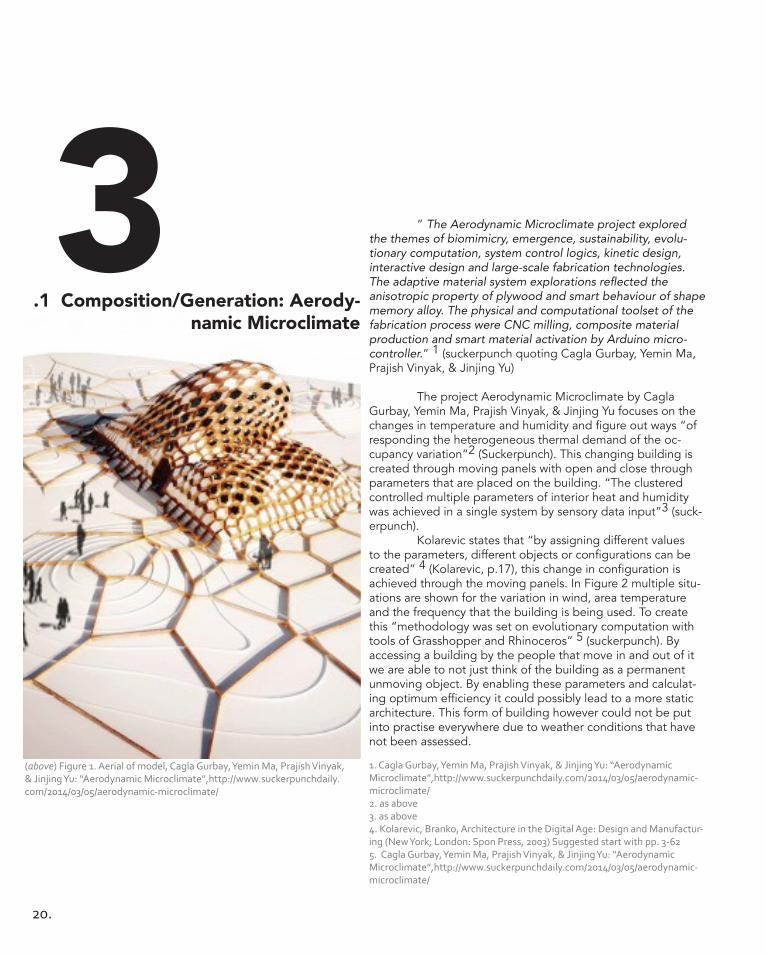
.1 Composition/Generation: Aerody-namic Microclimate
” The Aerodynamic Microclimate project explored the themes of biomimicry, emergence, sustainability, evolu-tionary computation, system control logics, kinetic design, interactive design and large-scale fabrication technologies. The adaptive material system explorations reflected the anisotropic property of plywood and smart behaviour of shape memory alloy. The physical and computational toolset of the fabrication process were CNC milling, composite material production and smart material activation by Arduino micro-controller.” 1 (suckerpunch quoting Cagla Gurbay, Yemin Ma, Prajish Vinyak, & Jinjing Yu)
The project Aerodynamic Microclimate by Cagla Gurbay, Yemin Ma, Prajish Vinyak, & Jinjing Yu focuses on the changes in temperature and humidity and figure out ways “of responding the heterogeneous thermal demand of the oc-cupancy variation”2 (Suckerpunch). This changing building is created through moving panels with open and close through parameters that are placed on the building. “The clustered controlled multiple parameters of interior heat and humidity was achieved in a single system by sensory data input”3 (suck-erpunch). Kolarevic states that “by assigning different values to the parameters, different objects or configurations can be created” 4 (Kolarevic, p.17), this change in configuration is achieved through the moving panels. In Figure 2 multiple situ-ations are shown for the variation in wind, area temperature and the frequency that the building is being used. To create this “methodology was set on evolutionary computation with tools of Grasshopper and Rhinoceros” 5 (suckerpunch). By accessing a building by the people that move in and out of it we are able to not just think of the building as a permanent unmoving object. By enabling these parameters and calculat-ing optimum efficiency it could possibly lead to a more static architecture. This form of building however could not be put into practise everywhere due to weather conditions that have not been assessed.
1. Cagla Gurbay, Yemin Ma, Prajish Vinyak, & Jinjing Yu: “Aerodynamic Microclimate”,http://www.suckerpunchdaily.com/2014/03/05/aerodynamic-microclimate/2. as above3. as above4. Kolarevic, Branko, Architecture in the Digital Age: Design and Manufactur-ing (New York; London: Spon Press, 2003) Suggested start with pp. 3-625. Cagla Gurbay, Yemin Ma, Prajish Vinyak, & Jinjing Yu: “Aerodynamic Microclimate”,http://www.suckerpunchdaily.com/2014/03/05/aerodynamic-microclimate/
(above) Figure 1. Aerial of model, Cagla Gurbay, Yemin Ma, Prajish Vinyak, & Jinjing Yu: “Aerodynamic Microclimate”,http://www.suckerpunchdaily.com/2014/03/05/aerodynamic-microclimate/
3

.21
(above) Figure 2. Parametric Change, Cagla Gurbay, Yemin Ma, Prajish Vin-yak, & Jinjing Yu: “Aerodynamic Microclimate”,http://www.suckerpunchdaily.com/2014/03/05/aerodynamic-microclimate/

22.
.2 Composition/Generation: Smithso-nian Institute
“A single computer program, written by Brady Pe-ters, an architect on the design team and a member of Foster + Partners’ Specialist Modelling Group (SMG), generated the geometry of the roof. The computer code was used to explore design options and was constantly modified throughout the design process. It was also used to generate the final geom-etry and additional information needed to analyse structural and acoustic performance, to visualise the space, and to cre-ate fabrication data for physical models.” 1 (Peters, p.13)
The roof over the courtyard of the Smithsonian Insti-tute by Foster + Partners shows a clear example of computer generate design with a piped mesh being lain over existing architecture. As stated in the quotation above several pa-rameters were enters so that multiple generations could be achieved to create the shape and structure of the roof. The firm Foster + Partners design process uses “computational designers working in internal specialist groups largely separate from the design teams. These groups act as internal consultan-cies and designers integrate with the design process to varying degrees depending on the needs of the project”2 (Peters, p. 11). The specialisation in computational design allowed them to generate many different iterations to produce the most ef-fective outcome to be placed on the building. By generating multiple outcomes they were able to test and examine what outcome would be most effective to the space. The meshed roof seems to float above the existing building and creates a large covered open space that seems as though it is outdoors. Through there generative design they considered the factor of the pre-existing building and how the new addition needed to react with it. I believe that this roof is simple and therefore is effective in its setting as it continues the conversation of the building. The interaction between the existing and new design is something that I can take away in my own LAGI design as external factors should be considered when generating design.
(above) Figure 1. Close up off roof, Foster + Partners, Smithsonian Institu-tion, Washington DC, 2007, http://www.fosterandpartners.com/projects/smithsonian-institution/
1. Peters, Brady. (2013) ‘Computation Works: The Building of Algorithmic Thought’, Architectural Design, 83, 2, pp. 08-152. as above
3

.23
(above) Figure 2. Angle shot of water reflection, Foster + Partners, Smithsonian Institution, Washington DC, 2007, http://www.fosterandpartners.com/projects/smithsonian-institution/

24.
Conclusion & Learning outcomes Through investigation over the past four weeks, I have discovered many presidents that I believe that I can learn from for my own design. Investigation into previous works for LAGI on pages 10-11 has shown me what I don’t and do want to achieve in my design and allowed me to view myself in a more critical way. By investigating piezoelectric energy as a sustainable energy source it sculpted the types of precedents that I wanted to gain knowledge from. From Part A I take away the concept of materiality and the ability to create a material of structure that is reactive and that will optimize my energy source. Along side my discoveries, the readings have allowed me to question my previous design ideals and think not just about sustainable practise and what it means to be “sustain-able” but about defuturing and what it means to design. This ideas have made me rethink my previous designs as I have pre-viously thought about design in a more analog why, through this exploration and discovering Grasshopper it has allowed me to transfer these thoughts and develop them into a more digital thinking.
4&5

.25
References Beckett & Babu, Interface /4, http://onlinelibrary.wiley.com/doi/10.1002/ad.1709/pdf
Cam Newnham, Melbourne Australia, RMIT Uni-versity, critic: Roland Snooks, http://www.suckerpunchdaily.com/2014/02/13/fibrosity/
Cagla Gurbay, Yemin Ma, Prajish Vinyak, & Jinjing Yu: “Aerodynamic Microclimate”,http://www.suckerpunchdaily.com/2014/03/05/aerodynamic-microclimate/
Energy Harvesting Technologies, By Shashank Priya, Dan-iel J. Inman, 2009
Ferry, Robert & Elizabeth Monoian, ‘Design Guidelines’, Land Art Generator Initiative, Copenhagen, 2014. pp 1 - 10 Foster + Partners, Smithsonian Institution, Washing-ton DC, 2007, http://www.fosterandpartners.com/projects/smithsonian-institution/
“Fresh Hills”, Mathew Rosenberg, Los Angeles (USA)
Fry, Tony (2008). Design Futuring: Sustainability, Ethics and New Practice (Oxford: Berg), pp. 1–16
Generator sizing, http://nextbigfuture.com/2011/04/piezo-electric-mems-boosts-vibration.html
High Definition: Zero Tolerance in Design and Produc-tion, January/February 2014, Volume 84, Issue 1, Pages 1–136, i–iii, Issue edited by: Bob Sheil, http://onlinelibrary.wiley.com/doi/10.1002/ad.1709/pdf Kinetic-Energy Harvesting Tiles, http://inhabitat.com/kinetic-energy-harvesting-tiles-generate-power-from-paris-mara-thon-runners/pavegen-energy-harvesting-tiles/
Kolarevic, Branko, Architecture in the Digital Age: De-sign and Manufacturing (New York; London: Spon Press, 2003) Suggested start with pp. 3-62 Oxman, Rivka and Robert Oxman, eds (2014). Theo-ries of the Digital in Architecture (London; New York: Rout-ledge), pp. 1–10
PaveGen tile, http://www.gizmag.com/pavegen-tiles-kinetic-energy-harvesting/20235/ Peters, Brady. (2013) ‘Computation Works: The Building of Algorithmic Thought’, Architectural Design, 83, 2, pp. 08-15
Piezoelectric generator, http://www.gizmag.com/mit-mems-device/19856/


.27
B

28.
Figure 1. Aerial view, http://www.iwamotoscott.com/VOUSSOIR-CLOUDFirgure 2. View through the cloud, As above

.29
Research Feild: Material Performance The material system that I decided to explore further was Material Performance with Iwamoto Scott ‘s 2008 Vous-soir Cloud installation. In previous precedents, materiality and its performance has been a key element that I have tried to explore. By exploring material performance in this context I hoped to grasp a further understanding and context in compu-tational design. Voussoir Cloud grasps inspiration from Gaudi and Otto’s concepts of chain modelling to find an efficient form1. Chain modelling is a concept where the form of a hang-ing chain was observed and gravitationally reversed with stone and concrete to create arches that were structurally sound and different in form. The chain modelling used allows for the low sloping arches and simple compressions of the structure. Each vault is divided into Delaunay tesselations which allows the panels to optimize the vault structure. The petal panels opti-mize the structure through bunching and smaller petals at the bases of the structure and at the ribs of the vault, opening up and spreading out as the go up and out. The wedge shaped masonry that is usually used in vaulted arches is able to be replaced with paper this wood panels due to the compression and tension factors realized through the chain modelling and Dealunay tesselation.
The thin wood panelling that is used creates its own surface tension through the curved folded seams. This ten-sion of the folds wanting to bulge out is what allows for the structural porosity within the constraints of the sheet material2. There are four different times of petals with zero, one, two or three curved folds which allows for each petal to behave in a different way and interact between each other. Designed on Rhino, Voussoir Cloud clearly shows what computational de-sign is capable of, or was in 2008, and creates an atmospheric space through mathematical spacing, shape formation and overall vault formation. 1. Iwamoto Scott, Voussoir Cloudm, 2008, http://www.iwamotoscott.com/VOUSSOIR-CLOUD2. As above
1

30.

.31
.1 Matrix Exploration: The Voussoir Cloud
2

32.

.33
From the above matrix I have selected four which I believe show the best outcome, or potential to learn from for future design generation. The four images (from top to bot-tom) show an alteration in the physics application, altering gravitational forces, an alteration in horizontal forces, a plugin in point change to a spiral formation with few points, and then many points. To select these iteration from my matrix I assessed material performacne and considered what type of materials i want to use within my own design. I think the organic, bulbous shapes of the first two could lend themselves well to thin film photovoltaic cells as a meterial as the shape allows for move-ment in the shapes and material. The bottom two present a more ridid structure with hidden elements and confusion to the eye as well as the ability for moving element for kinetic energy. When modeling these iterations my aim was to break to model, to distort it and push it to its boundaries. The first two do not essentially show this but show where i began and the physics capabilities of the program which could be used to my advan-tage.
.2 Matrix Exploration
2

34.
EXOtique was a quick, 5 day fabrication installation at Ball State’s College of Architecture where projectione was invited to lead a group of students from design through to fabrication. They had a $500 budget and a strict schedule to assemble and make a functioning hanging structure over a foyer of the school. Computational tools such a Rhino and Grasshopper aiding in the design and lead the direction the system was heading. The aim was for students to use these tools as pure generators of representation, elegantly put “As designers and creative thinkers, we do not have to lean on these tools for the purposes of imagery; imagination can act as renderer, and understanding of materiality acts as logic in the physical world.”1, yet to ease and speed up the design process generative design process are used.
The structure uses hexagonal panels and triangulated circle cut outs to create a lit drop ceiling over the space. No hardware or connectors where used in the project with all ele-ments being considered in the design process. This allowed for a cut in costs, using the material to its full potential. EXOtique considers material performance and optimizes this in its design intellectually and elegantly. This philosophy should be consid-ered in our LAGI design, where materiality acts as a main factor in energy efficiency to achieve the lowest embodied energy cost and least waste. The geometric complexity of the design is something else which we would like to embody in our de-sign as its creates an effective simple surface with flexibility to be placed in any environment.
.1 Case Study 2.0: EXOtique
1. EXOtique, http://www.projectione.com/exotique/
3

.35
(top) Firgure 1. EXOtique, http://www.projectione.com/exotique/(bottom) Figure 2. Close up of panels and cut outs, http://www.projectione.com/exotique/

36.
1 Hexagonal gridUsing the hexgrid function and offset-ting the hexagonal shape, we have created a hexagonal pattern which mimics the panel tessellation of the EXOtique installation. The integers used for the grid were odd numbers in order to satisfy the tessellation requirements of the hexagonal shape. We have used an x integer of 3 and y integer of 5.
2 BoxAfter establishing the hexagonal grid pattern, we established a panel space using this grid as a base. The box is created by the joining of points, whose locations are informed by the grid geometry through use of the subtract command. The rectangular space serves as a pan-el, which allows the hexagonal pattern to be applied to our lofted surface.
3 LoftApplying the loft command to a collection of curves creates a planar surface to which the hexagonal panel geometry. The lofted plane is representative of the lofted shape of the EXOtique installation.
.2 Case Study 2.0: EXOtique
3

.37
4 ApplyingThe hexagonal grid was applied to our lofted surface by morphing the grid surface, the box panel and the loft surface box. The combination of shape and pattern creates the overall form which is iden-tifiable as a variation of EXOtique.
5 AdjustingExperimentation with the surface loft shape, and of the values of various commands such as the surface divider, facilitated minor adjustments to our form that resulted in a greater level of resemblance to EXOtique.
6 Attempt at point charges The EXOtique panels have circular cut-outs. We recreated this circular pattern using point charges. We divided our hexagonal surfaces into points. We then created point charges, altered by equation which controls the circle radius. This new sur-face was then mapped onto the loft. We encountered an error in executing this, however the simulation was still completed. EXOtique is lit with LED bulbs attached to some panels, the circles are only present on the panels which are not lit. We could not repli-cate the inconsistency of the circular patterning, as we could not find a way to instruct point charges to only effect certain portions of the grid surface.
Similarities and differencesSimilaritiesGeneral curvature while keeping rigid structure because of the hexagonals The hexagonal panels follow the curvature of the loft, rather than being two-dimensional pieces placed together to create a lofted shape. DifferencesThe configuration of the circular cut-outs is dissimilar to that of our definition in that our circular pattern expressed itself in singular lines, rather than a concentric configuration. The outside edges of EXOtique are limited to the borders of the hexagonal shapes, rather than adhering to the shape of the lofted surface. Our definition adheres to the boundaries of the loft.
Where would we like to go next? Increase dimensionality by splitting the lofted plane to fold it into different directions. Additionally, we would extrude some panels to create a more 3 dimensional effect.We would increase the ‘sharpness’ of the form by implement-ing panelised ribs which would protrude from the loft.

38.
4
.1 Technique: Development

.39

40.
.2 Technique: Development
exotiqueIn this iteration we redid our reverse engineer of EXOtique to create a piped frame with hexagonal panelling on them. This different iteration meant that we would be able to achieve different outcomes and generations in our matrix through using different iterations and different methods to receive the same outcome.
piping patternIn this render the geometric piping was offset to create a two layered structure with no surface between the pipes. This one was picked as we believed the shape and movement was emotive whilst still retaining the material texture we want to create in our structure. This structure could be applied to the site in different ways, vertically upright, horizon-tal in the sky or on the ground, or even over hanging the water.
tensile tunnelIn this rendering we looked at removing the curve at one end of the structure and replacing it with a point, this creates a pinched end. By removing the surface and only having piping it allows for us to place piezoelectric film within them that will react to external factors such as wind and hum contact. To create maximum accessibility and efficiency, this structure would be placed horizontal to the site so that pedestrians could walk though and interact with the structure.
4

.41
phat pipesThis piping iteration enlarged the pipes creating no surfaces in between them and creating a piped meshed structure. This structure could be used as a walkway and if panels where ap-plied to the structure it then could be clad in photovoltaic cells to collect sunlight.
turning towerThis iteration created a structured twisted tower structure with a ribbed facade. We picked this one as I feel an energy could be placed on this structure very easily due to its flat surfaces at 360 degrees. I feel that this structure could be pushed and expanded to challenge to site and to create a breathing land-scape if elements of it where made to move.
We have interpreted the brief as prompting a design which employs natural site conditions as a means of energy genera-tion.Our intent is to create something that responds to the dynamism of on-site environmental factors in a way that is interactive with users. The challenge is to incorporate geometric complexity and expression of parametric design, while maintaining navigability in our structure. We have employed the algorithmic design process of geometric paneling in conjunction with solar and kinetic energy generators with a focus towards minimizing embodied energy through use of local recycled materi-als. Our algorithmic design strategy, geometric panelling, has been influenced by our explorations of precedents Voussoir Cloud and EXOtique. Consideration of material function, as in Voussoir cloud, inspired integration between our generators and our structure, in turn informing our decision to employ photovoltaic and piezoelectric paneling. EXOtique emphasizes the relative simplicity of panel fabrication. As embodied energy is a concern for sustainable development, we chose to inte-grate paneling into our design. Moreover, we will employ recycled steel from the surrounding industrial area for the frame in order to minimize cost and energy of transport and production. The Voussoir cloud cells are based on the Delaunay tessel-lation, and EXOtique on an offset hexgrid. Having worked with these geometric grid forms and achieving interesting results, we chose to continue down this pathway.

42.
Technique: Prototypes
Through genereative exploration and presedant research, material performance has transformed into a key ele-ment of design that we want to be portrayed in our design. A geometrically complex surface acts as both a physically beauti-ful element but also works practically when incorporated with photovoltaic cells on a surface. Here is a modelled example of a triangulated surface that we want to project onto our work.
This triangulation would be perfect for photovoltaic cells as they would allow for them to be placed on an efficient angle. Photovoltaic cells convert the energy of light directly into electricity.Specifically we have chosen monocrystalline solar cells: the most efficient, durable and space efficient and crystalline cells, which also suffer less adverse effects from temperature in-crease than polycrystalline.These cells are generally used in the form of panels, and so are applicable to our strategy of geo-metric panelling. Our other energy that we want to incorporate is piezoelectric cells. Piezoelectric ceramics when affected by pressure or vibration have the capacity to generate electric voltages. Piezo electric actuators convert electrical signals into physical displacement, this could be used to control the move-ment of elements within our dynamic, responsive structures.
5

.43
Through prototyping and exploration we discovered a few thing. The “tower” design was effective and simple and had the ability to have multiple facades if we made it possible for it to rotate. This dynamic movement could be used to our advantage to harness energy on the site. In prototyping the pipes we found that there was elements in the grasshopper file which we did not realize where there, which is why our 3D print came out with more joining pipes. I definitely feel as through we need to revise our grasshop-per file and maybe start again with our design with elements of what we want to achieve in mind. The dynamic nature of the tower is something that I feel we should expand.

44.

.45
Technique: Proposal Pipes is an interactive constellation of piped walkways clad with photovoltaic cells and piezoelectric fitted doors. The pipe directions are based on overlayed summer and winter wind rose data for the site, maximizing kinetic energy potential. The central area will be a meeting point of all the pipes with sitting area for users. The door from each pipe to the central space is constructed of translucent, coloured piezoelectric panels. The doors are fitted with piezoelectric actuators which will detect changes in wind velocity and open or close the door in response. The greater the wind speed, the further the door closes. This places panels more perpendicular to stronger winds to optimize energy intake. The door colouring will be projected into the floor of the space; the door will be lit with a small percentage of the energy generated to emphasise the projection. Wider projections denote higher wind velocities (refer to diagrams). The interior space is protected from large wind tunnels as door are automatically further closed in these areas. The exterior of the structure is cladded mono crystal-line photovoltaic panels which are triangulated to allow for individual angling for optimal light capture.Tessellation tower is a rotating solar and wind energy har-nessing sculpture. Steel offcuts will make up the frame of the structure, which will be clad in mono crystalline photovoltaic cells and piezo-actuators. The tower itself is divided up into rectanglular modules, which move independently as a result of wind velocities affecting the piezo actuators. Each module will be covered in mono crystalline photovoltaic cells on the top and the sides of the rectangular structure to harness solar energy. The tower visually demonstrates changes in wind pat-terns but is limited in user interaction.
6

46.
Learning Objectives and Outcomes Over the past weeks I think my grasshopper skills have been lacking and it has meant my computational design-ing isn’t standing up to the ideas that I have. The feedback received for interim presentation was helpful and definitely what was needed to help my group pull up our socks and work out what we want to achieve in this subject. I definitely think that we should push the tower idea further and work out how it can effectively be used on the site. What is we just kept the ro-tation idea and made the whole site out of rotation panels that generate energy and create a hilled landscape on a once flat site. What if we kept this tower idea but elongated elements so that users could stand on them or what if we had different activities on each of these elements, all generating kinetic energy. I think there is definitely some potential it just involves a lot of hard work from here until the end of semester.
At the beginning of the subject guide there is a list of learning objectives for this subject. Objective 2 is the “ability to generate a variety of design possibilities for a given situa-tion”, I think in my work when I am given a definition, like in Voissoir Cloud, I am able to push and challenge the design, however when we had to reverse engineer EXOtique I don’t think I push the design to its full potential. I don’t think I was able to achieve Objective 4, “an understanding of relation-ships between architecture and air”. I believe that over the next few weeks I need to work hard and push myself to create something that is both visually appealing and geometrically complex. I believe that if I push myself in Grasshopper, more then I had before, a design I am proud of will come out. From the past crit and seeing where everyone else is at, I know that there is a lot of work that needs to get done but I think it is possible if i work hard.
7

.47
References EXOtique, projectione, 2005, http://www.projectione.com/exotique/
Iwamoto Scott, Voussoir Cloudm, 2008, http://www.iwa-motoscott.com/VOUSSOIR-CLOUD


.49
C

50.
.1 Design Concept
= curves with point charge = lofted = triangulted mesh

.51
.1 Design Concept After last interim submission, with the feedback that we received, we decided to change our design strategy and go back to something more simple. We knew that we wanted to still use piezoelectric cells as they worked effectively to the brief as they express there energy production through movement. For the primary function of the site we wanted to encourage discussion and awareness of renewable energy whilst also creating a functional community space where people could come and go for walks, have a picnic etc.
To redesign our structure we wanted to create a triangulated frame that could be walked in, around and on allow for maximum human interaction with the piezo-electric cells, that would be mounted in a selection of these triangulated spaces. To create this we played around with different methods of triangulation, in the end we ended up creating a space frame, as it was the most structurally possible. From here we then proceeded to play around with site configuration, how many would be used and what was the most efficient at generating energy.
= space frame created = U and V adjusted = divided into cables/steel and piped
1

52.

.53
.2 Design Concept As the structure is using piezoelectric energy generated through the movement of the wind, it was necessary to access the orientation of the structure in relation to the wind flow as well as the circulation of humans through the site. We accessed many different types of orientations from a singular structure, two structures, different ways up, circular, flower-like arrays and vertically stacked. From this exploration we decided to test two different iterations, a singular model spanning half the site and multiple “flower” arrangements on the site. We measured the potential power output and the expected energy output for each structure with piezoelectric fixed to the optimum areas. Through our research into piezoelectric cells we found many different variations of how the cells could be attached and what the cells were constructed of. We tested different flexible piezoelectric devices (FPED) of fabrics, clear cells on a hinge, semi circle balls on a surface and reactive nanowires. Through prototyping and graphical comparison of energy generation (as seen in figure 1) we decided to go with with strips of zinc oxide piezoelectric nanowires which produce electricity from their fluttering motion on the FPED. This surface roughness “can cause micro turbu-lence around the FPED and the pressure fluctuation make the FPED vibrated. The electric powers of both roughness cases are 10%-20% larger or more than that of the normal case without the roughness case, especially at higher wind speed.” (Wind Energy Harvesting Using FPED, p. 1050-1051).
1
Hidemi Mutsuda, Junpei Miyagi, Yasuaki Doi and Yoshikazu Tanaka, “Wind Energy Harvesting Using Flexible Piezoelectric Device”, Journal of Energy and Power Engineering 7 (2013) 1047-1051
Graph from, Hidemi Mutsuda, Junpei Miyagi, Yasuaki Doi and Yoshikazu Tanaka, “Wind Energy Harvesting Using Flexible Piezoelectric Device”, Journal of Energy and Power Engi-neering 7 (2013) 1047-1051
Summer and Winter wind rose diagrams

54.
Potential power output based on max wind veloc-ity 3880 mW/h approx.
Expected power output based on average veloc-ity 256 mW/h approx.

.55
Potential power output based on max. wind velocity 7315 mW/h approx.
Expected power output based on average veloc-ity 523 mW/h approx.
1.3 Mulitple structures vs. Single structure

56.
.4 Assembly and ManifacturingThe steel frame members for the structure will be acquired from surrounding industrial areas offcuts e.g. ship yard. The space frame members can be manufactured in surrounding factory spaces. The structure will be finished with a brush polish whilst maintaining a low surface roughness to optimize corrosion resistance. Steel is one of the least corrosive met-als, which makes it perfect for the site, as it will be exposed to water and excessive wind. Tension cables in the structure will be fitted with suspension clamps as necessary, which can be manufactured by NKT Cables, Stenlille, Denmark. The piezo-electric panels will be fitted to an aluminum frame on both sides; MicroFlex, Denmark can manufacture these. Component parts will enter the site from the city side. The tension cables and piezoelectric panels will be manufactured off-site, there-fore they will be delivered to the factory spaces for storage in order to avoid exposure to elements, this means transport from the warehouse space to the design boundary will be needed. Delivery by sea is also possible, but unnecessary as all components are to be produced within Denmark to minimize transport costs and energy.
The assembly and manufacturing of the structure is something that needs to be considered. The structure can be assembled on site given the large 500 000 m2 surface area, this lowers the embodied energy cost as the steel members are produced in close proximity to the site. This however would mean it would need to be weather protected and construction would not be able to be conducted under poor weather conditions, which is a likely possibility. Construction would need to be conducted in parts due to piezoelectric panels being at 14m at the highest point of the structure. Our proposed method of construction would be: 1. Welding of steel members via welding of tennoned connection. 2. Fitting of tension cables connected via suspension clamp. 3. Attachment of FPEDs (both sides) encased in pre-installed aluminum frame. Ensure that wires run through proscribed steel member as per the electrical plan. 4. Connect all parts, ensuring safe connections be-tween wiring, and welding of all steel connections leaving no gaps for water penetration.
1

.57
Available space for storage and manufacture Transport/ accessibility routes
1. Connection between tenonned steel members
2. Fitting of tension cables connected by suspension clamp
3. Attachment of FPEDs (both sides) encased in pre-installed aluminium frame. Ensure that wires run through proscribed steel member as per the electrical plan.

58.
Tectonic Elements
2
4.
1. 2. 3.
5.

.59
In the prototyping process we wanted to explore different styles of piezoelectric devices as they would be the first things that people would see when they entered the site. These devices are something that we also wanted people to have an interaction with to connect with the site and the clean energy of Copenhagen. As aesthetics were a major element it was key that we explored different ways for us to generate energy. We first build a clear piezo cell on a hinge (1) that would flap in the wind to generate energy. We liked this however this flapping motion would not generate enough energy and having just clear panels defeated our purpose of having an interactive ele-ment with the people on the site. In number 2 we prototyped piezoelectric fabric, that we hoped would create a fluttering movement to the structure. However as we researched more and played around with our prototype we realized that the fabric did not have as much movement as we wanted in it. In our research of piezoelectric cells we discovered a panel that
had semi circle spheres on it that generated energy through kinetic wind movement through the friction of the surface. After modeling it up we decided this was not the type of im-age we wanted to create in our structure. The spheres made it seem “space-like” and not something we wanted to portrayed. Finally we modelled up a piezoelectric device that used strips of zinc oxide piezoelectric nanowires which produced electric-ity from their fluttering motion fibers on the it. After model-ling it both physically and on the computer (as seen above) we decided that this was the FPED that we wanted to use. This cell generated the most energy out of all that we tested and also performed better under high wind conditions. The individual nanowires that can move independently will create a movement to the structure, visually showing the wind passing through the site. This movement will create an interaction be-tween people on the site and the structure as they will be able to see the energy being directly generated.
Renders of the FPED configuration for the structure

60.
.1 Final Model
3

.61
Photographed 3D powder printed scale model

62.
South Elevation
East Elevation
North Elevation
Aerial View

.63
C .2 Tectonic Elements
Section A:A
Section B:B Site Plan
.2 Elevations and Sections
3

64.
.3 FPED placement
The placement of the FPED can create different moods to the site by creating closed weather protected areas, areas for sitting, areas for walking through and playing on the structure and areas where people can interact with the FPED. With this in mind we investigated different configurations by paneling the structure evenly and by having more concentrat-ed areas. Through rendering and site assessment we decided to go with the configuration as seen as below. This configura-tion optimizes the wind rose for the area therefore optimizing
3the amount of energy that will be generated by the structure. The northern part of the structure has a high concentration of FPED which will create an enclosed area protected from the weather and therefore a seating area. By having the FPED down at ground level people will be able to touch and interact with the cells. This interaction is somehting that we wanted in our design as the structures aim is to education and start discussion about renewable energy.
Final Configuration

.65
Configuration1
Configuration2

66.
Fluttering Canopy Fluttering Canopy is an energy generating struc-ture that aims to start discussion and educate the people of Copenhagen about clean energy. The space-framed structure, fitted with piezoelectric devices, transforms the surround industrial area of Refshaleoen by creating a public park for walking, cycling and picnicking. Across the river at the Little Mermaid, people can see the peak of Fluttering Canopy as it flutters in the wind generating energy.
Flexible Piezoelectric Devices (FPED) Fitted to the structure are FPED which generate electric voltages when a pressure or vibration is acted on the device. Fluttering Canopy uses the natural movement of the wind to generate energy; this stimulates the strips of zinc oxide piezoelectric nanowires that are distributed across the FPED. The nanowires create a fluttering motion visual repre-senting the energy that is being created to people on the site. The Fluttering Canopy covers 85 meters of the site and is 35 meters wide. Its maximum height is 14 meters high on the western side of the site. The public enters the structure from two main entranceways, one from the city side, at 5 meters, and one from the dockside, at 4 meters. FPED’s are placed mainly on the east to west axis in the northern part of the structure. To optimize energy efficiency as we considered the average wind velocities for the area and also places the FPED on the inside and outside of the structure. Fluttering Canopy proposes to hold around 3058m2 of FPED resulting in:Potential power output based on maximum wind velocity = 7315 mW/h approx.Expected power output based on average velocity = 523 mW/h approx.The energy will be transported through wiring to grid-tie inverters concealed within the steel piping. These will then in-
4tern connect to the distribution panel tat will be situated close to the city entrance of the site at ground level. From here the galvanized protected wires will be placed underground to transport the generated energy back to Copenhagen.The space-framed structure of Fluttering Canopy uses a con-figuration of tension cables and interlocked struts to create a strong, rigid and lightweight truss structure. The space frame members will be tennoned together and welded to conserve space by removing the need. Suspension clamps will be used to connect the FPED to the structure. By substituting steel members with tension cables that are classified as secondary structure it will reduce the complexity of construction.
Environmental Impact The aim of LAGI competition was to create an infra-structure art space that showcases sustainable clean energy in Copenhagen as they aim to become the first carbon neutral city by 2020. In undertaking this competition we chose to use Kinetic energy as it expressed its energy generation through movement and it can have direct human interaction. When designing our structure we wanted to emphasis the act of energy production and therefore left the grid-tie inverter and distribution panel exposed at an entrance. As people walk around the site and enjoy the transformed landscape they are constantly reminded of the main purpose. As a team we are aware that the structure does not generate that much energy; its main aim is to educate and start discussion about clean energy. Therefore we decided that all energy generated by Fluttering Canopy would go directly back to the grid instead of being used to light the structure for example. As the main aim for the project was clean energy we also tried to generate a design that made a low environmental impact. When con-sidering materials we tried to reduce our embodied energy by using steel off cuts from the surrounding industrial area.

.67
Renders approaching “Fluttering Canopy”

68.
Learning Objectives and Outcomes Over the past few weeks I think my team and I have developed our proposal to a more resolved design. We have aim to created something that is clear and concise and meets the design brief. After the final presentation we went away with feedback that we had received and tried to develop more pan-eling iterations and more atmospheric renders to explore how people would interact with the site. In part C I think we have tried to achieve many more of the learning objectives of the course and definitely in the weeks after the final presentation we have considered the relationship between architecture and air. Even though our design is something very simple I think we were able to produce as argument that make it possible for this design to be built.
During this semester I have challenged myself into thinking about design generation in a different way to what I am use to. I think over this course my knowledge and problem solving skills in grasshopper have definitely improved as I have tried to continue pushing myself.
5

.69
References
Hidemi Mutsuda, Junpei Miyagi, Yasuaki Doi and Yoshikazu Tanaka, “Wind Energy Harvesting Using Flexible Piezoelectric Device”, Journal of Energy and Power Engineer-ing 7 (2013) 1047-1051