Air Cooled Inverter Chiller. Product Lineup & Features Product Lineup & Features Components...
103
Technical Training Technical Training Air Cooled Inverter Chiller Air Cooled Inverter Chiller Air Cooled Inverter Chiller
-
Upload
tamsin-turner -
Category
Documents
-
view
222 -
download
1
Transcript of Air Cooled Inverter Chiller. Product Lineup & Features Product Lineup & Features Components...

Te
chn
ica
l Tra
inin
gT
ech
nic
al T
rain
ing
Air Cooled Inverter ChillerAir Cooled Inverter Chiller
Air Cooled Inverter Chiller

Te
chn
ica
l Tra
inin
gT
ech
nic
al T
rain
ing
Air Cooled Inverter ChillerAir Cooled Inverter Chiller
Product Lineup & FeaturesProduct Lineup & Features
ComponentsComponents
Schematic diagramSchematic diagram
Inverter technology Inverter technology
Control AlgorithmControl Algorithm
Chiller Panel ControllerChiller Panel Controller
Self diagnosis & TroubleshootingSelf diagnosis & Troubleshooting
InstallationInstallation
Content

Te
chn
ica
l Tra
inin
gT
ech
nic
al T
rain
ing
Air Cooled Inverter ChillerAir Cooled Inverter Chiller
Product Lineup & Features

Te
chn
ica
l Tra
inin
gT
ech
nic
al T
rain
ing
Air Cooled Inverter ChillerAir Cooled Inverter Chiller
5ACV30 CR5ACV30 CR
Product Lineup
5ACV55/75 CR5ACV55/75 CR
5ACV100/135/210 CR5ACV100/135/210 CR

Te
chn
ica
l Tra
inin
gT
ech
nic
al T
rain
ing
Air Cooled Inverter ChillerAir Cooled Inverter Chiller
ModelCapacity (kW)
Cooling Heating
5ACV030CR 7.94 9.665ACV055CR 14.65 16.125ACV075CR 20.52 21.995ACV100CR 27.80 29.305ACV135CR 38.54 41.475ACV210CR 58.62 61.55
Capacity

Te
chn
ica
l Tra
inin
gT
ech
nic
al T
rain
ing
Air Cooled Inverter ChillerAir Cooled Inverter Chiller
Conventional Back to Back Circuits BPHE
Primary Circuit 1 Primary Circuit 2
Secondary Circuit
Features
Primary Circuit 1 Primary Circuit 2
5ACV True Dual Circuits BPHE
New Technology BPHE- True Dual Circuits
Te
chn
ica
l Tra
inin
gT
ech
nic
al T
rain
ing
Air Cooled Inverter ChillerAir Cooled Inverter Chiller
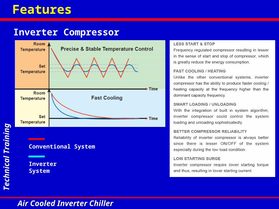
Conventional System
Inverter System
Features
Inverter Compressor

Te
chn
ica
l Tra
inin
gT
ech
nic
al T
rain
ing
Air Cooled Inverter ChillerAir Cooled Inverter Chiller
Inverter is based on ESEER due to part loading (25%-50%-75%-100%).
Features
Higher Seasonal EER
Te
chn
ica
l Tra
inin
gT
ech
nic
al T
rain
ing
Air Cooled Inverter ChillerAir Cooled Inverter Chiller
Features
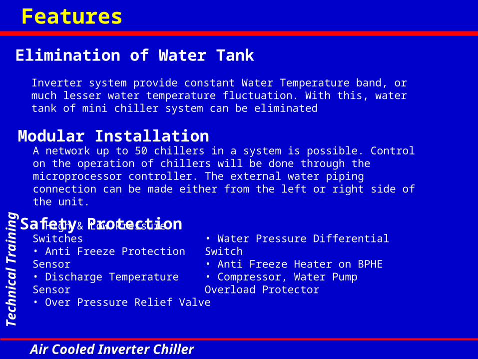
Inverter system provide constant Water Temperature band, or much lesser water temperature fluctuation. With this, water tank of mini chiller system can be eliminated
Elimination of Water Tank
A network up to 50 chillers in a system is possible. Control on the operation of chillers will be done through the microprocessor controller. The external water piping connection can be made either from the left or right side of the unit.
Modular Installation
• High & Low Pressure Switches • Anti Freeze Protection Sensor• Discharge Temperature Sensor• Over Pressure Relief Valve
Safety Protection• Water Pressure Differential Switch• Anti Freeze Heater on BPHE• Compressor, Water Pump Overload Protector

Te
chn
ica
l Tra
inin
gT
ech
nic
al T
rain
ing
Air Cooled Inverter ChillerAir Cooled Inverter Chiller
Components

Te
chn
ica
l Tra
inin
gT
ech
nic
al T
rain
ing
Air Cooled Inverter ChillerAir Cooled Inverter Chiller
Components
Variable speed fan motors (100%, 70% & 50%)
Heat exchangers with gold fin as standard
Water pump
True dual circuits BPHE (Brazed plate heat exchanger)
Expansion tank ( 8L)
Control box assembly
Coil guards
Fan guards

Te
chn
ica
l Tra
inin
gT
ech
nic
al T
rain
ing
Air Cooled Inverter ChillerAir Cooled Inverter Chiller
Components
Variable drive system compartment
Fixed drive system compartment
High pressure switch(NC) 600 psi – open, 480psi – close.Low pressure switch(NC) 18 psi – open, 28 psi – close.
Pump OLP (overload protector)
Differential pressure switch
Over pressure relief valve
Anti freeze heater on BPHE
Compressor OLP (overload protector)
Chiller panel controller
Fixed speed scroll compressor (R410A)Variable speed scroll compressor (R410A)
EXV (Electronics expansion valve
4 Way valve

Te
chn
ica
l Tra
inin
gT
ech
nic
al T
rain
ing
Air Cooled Inverter ChillerAir Cooled Inverter Chiller
Components
Control box assembly
Power board
IPM board(Intelligent power module)
Main boardMagneticcontactors
EMI filterCapacitor board
PFC capacitor(Power factor correction)
Uni-directional bridge diode
3 phase rectifier bridge diode
Fan capacitors
PTC starter(Positive temperature coefficient)

Te
chn
ica
l Tra
inin
gT
ech
nic
al T
rain
ing
Air Cooled Inverter ChillerAir Cooled Inverter Chiller
Schematic diagram

Te
chn
ica
l Tra
inin
gT
ech
nic
al T
rain
ing
Air Cooled Inverter ChillerAir Cooled Inverter Chiller
Condenser Coil 1
Acc
Acc
Liq Rvr
Liq Rvr
BPHE FS
Condenser Coil 2
DischTemp 2
(Disch Comp 2)
DischTemp 1
(Disch Comp 1)
InvComp
StdComp
SuctTemp
(Suction)
HP1
HP2
LP2
LP1
Cond InTemp 1
(Condenser)
Cond OutTemp 1
(Def Comp 1)
BPHE OutTemp
(BPHE Out)
BPHE InTemp
(BPHE In)
EWT (Water In)
LWT (Water Out)
Pump
Cond OutTemp 2
(Def Comp 2)
FilterDrier
Heating Cap Tube
Check valve
Cooling Cap Tube
Check valve
FilterDrier
EXV
O/A Temp(Outdoor Air)
Summary Pages-Screen 3
Display Menu-Defrost Sensor
Display Menu-Inverter Chiller
Display Menu-Discharge Sensor
5ACV100CR
4WV
4WV
Schematic diagram
Inverter chiller schematic diagram

Te
chn
ica
l Tra
inin
gT
ech
nic
al T
rain
ing
Air Cooled Inverter ChillerAir Cooled Inverter Chiller
Inverter technology

Te
chn
ica
l Tra
inin
gT
ech
nic
al T
rain
ing
Air Cooled Inverter ChillerAir Cooled Inverter Chiller
Inverter technology
• Less Start & Stop • Fast Cooling/ Heating
• Smart Loading/ Unloading
• Better Compressor Reliability
Conventional System
Inverter System
What Inverter can do for us ?

Te
chn
ica
l Tra
inin
gT
ech
nic
al T
rain
ing
Air Cooled Inverter ChillerAir Cooled Inverter Chiller
Inverter technology
Brief Introduction on Inverter Technology
Inverter control technology convert AC supply to DC and convert it back to AC. The frequency & voltage of each phase can be controlled and applied on asynchronous motor for variable load control.
Inverter basic structure

Te
chn
ica
l Tra
inin
gT
ech
nic
al T
rain
ing
Air Cooled Inverter ChillerAir Cooled Inverter Chiller
• To minimize emission effect (EMC) and raise immunity level (EMS), a LC filter is used.• PTC resistor acts to cushion start up current to capacitor.• Diode bridge inverts AC to DC.
Inverter technology
Rectification circuit

Te
chn
ica
l Tra
inin
gT
ech
nic
al T
rain
ing
Air Cooled Inverter ChillerAir Cooled Inverter Chiller
• PTC capacitor acts to restraint PF losses caused
by fluctuation of DC voltage.
Inverter technology
DC stage
Te
chn
ica
l Tra
inin
gT
ech
nic
al T
rain
ing
Air Cooled Inverter ChillerAir Cooled Inverter Chiller
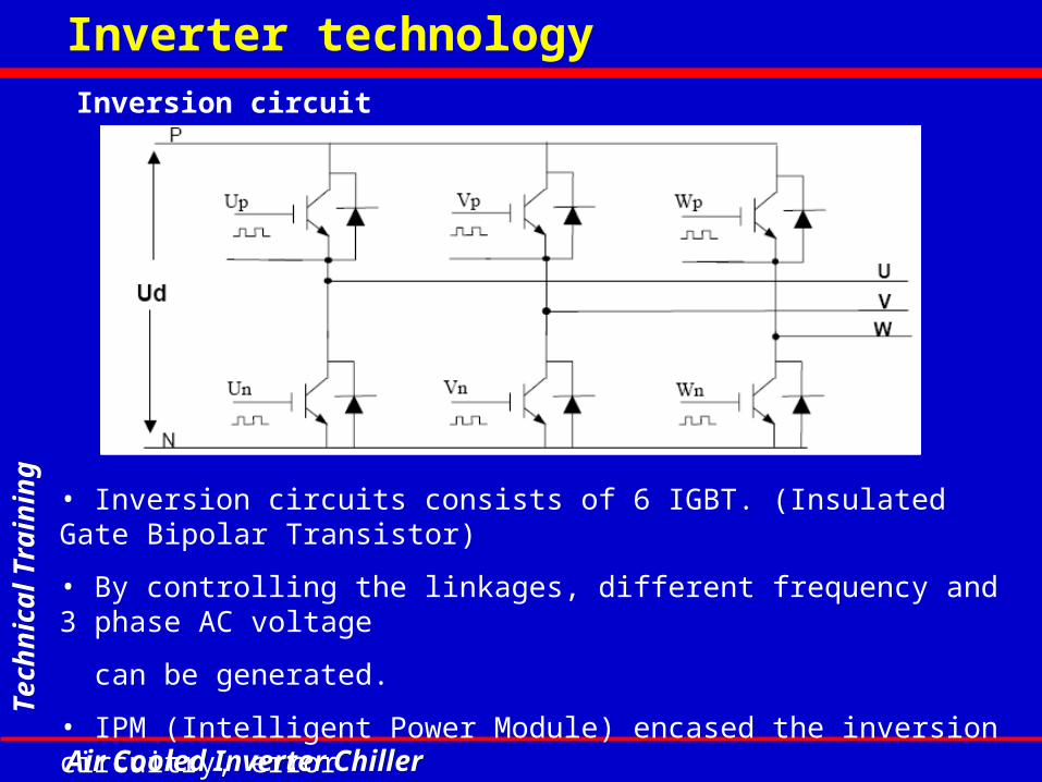
• Inversion circuits consists of 6 IGBT. (Insulated Gate Bipolar Transistor)
• By controlling the linkages, different frequency and 3 phase AC voltage
can be generated.
• IPM (Intelligent Power Module) encased the inversion circuitry, error
detection & protection features.
Inverter technologyInversion circuit

Te
chn
ica
l Tra
inin
gT
ech
nic
al T
rain
ing
Air Cooled Inverter ChillerAir Cooled Inverter Chiller
By computing the on-off frequency and timing of IGBT, a series of output voltage pulse widths can be integrated to form a sine wave for application on VVVF. (Variable Voltage Variable Frequency)
Inverter technology
SPWM ( Sine pulse width modulation )

Te
chn
ica
l Tra
inin
gT
ech
nic
al T
rain
ing
Air Cooled Inverter ChillerAir Cooled Inverter Chiller
• Every inverter chiller has its typical characteristic and VVVF (variable
voltage variable frequency) curve.
• To control Asynchronous motor, it is desirable to maintain magnetic
flux for torque requirement.
• Excessive of magnetic flux will cause excitation and diminish the flux.
• To maintain optimum flux, the voltage varies with frequency.
Inverter technology
VVVF (Variable voltage variable frequency)

Te
chn
ica
l Tra
inin
gT
ech
nic
al T
rain
ing
Air Cooled Inverter ChillerAir Cooled Inverter Chiller
Control Algorithm

Te
chn
ica
l Tra
inin
gT
ech
nic
al T
rain
ing
Air Cooled Inverter ChillerAir Cooled Inverter Chiller
Variable Drive Compressor Control
Cooling mode
Start up condition :
• Pump runs normally for 2 minutes *
• 2°C T water return – T set 4°C
• No irreversible errors in variable drive and the systems• Satisfy a delay of 3 minutes before restart #
Note : If fixed drive system starts first, the variable drive system should trail after 30 sec.
* Depends on Parameter P2 (flow switch alarm delay at pump start. Min 0s, max 199s, default 120s )# Depends on Parameter C2 (compressor min stop time. Min 0s, max 1990s, default 180s)
For example :Return water temp.= 14 to 16 °CSet temp = 12°C T = 2 to 4°C
Control Algorithm

Te
chn
ica
l Tra
inin
gT
ech
nic
al T
rain
ing
Air Cooled Inverter ChillerAir Cooled Inverter Chiller
Cooling modeCooling mode selected water pump starts Outdoor fan starts variable drive compressor starts
Rated Freq.
55Hz
5Hz
t
3 min 5 sec 1 min
ONOFF
ONOFF
Variable drive comp
Outdoor fan
Outdoor fan will start 5 sec before compressor start
Inverter compressor will start from 5Hz to 55Hz and maintain this frequency for 1 min.
Increase to rated frequency with the rate of 1Hz/s5ACV100CR=75Hz
5ACV135CR=95Hz
Control Algorithm

Te
chn
ica
l Tra
inin
gT
ech
nic
al T
rain
ing
Air Cooled Inverter ChillerAir Cooled Inverter Chiller
Cooling mode
Shut down condition :
• Cooling mode terminates, OR
• T water return – T set -2°C
• Variable drive system error occurs, OR
For example :Return water temp.= 10°CSet temp = 12°C T = -2°C
Control Algorithm

Te
chn
ica
l Tra
inin
gT
ech
nic
al T
rain
ing
Air Cooled Inverter ChillerAir Cooled Inverter Chiller
Heating mode
Start up condition :
• Pump runs normally for 2 minutes *
• 2°C T set - T water return 4°C
• No irreversible errors in variable drive and the systems• Satisfy a delay of 3 minutes before restart #
* Depends on Parameter P2 (flow switch alarm delay at pump start. Min 0s, max 199s, default 120s )# Depends on Parameter C2 (compressor min stop time. Min 0s, max 1990s, default 180s)
Note : If fixed drive system starts first, the variable drive system should trail after 30 sec.
For example :Set temp = 40°CReturn water temp.= 36 to 38 °C T = 2 to 4°C
Control Algorithm

Te
chn
ica
l Tra
inin
gT
ech
nic
al T
rain
ing
Air Cooled Inverter ChillerAir Cooled Inverter Chiller
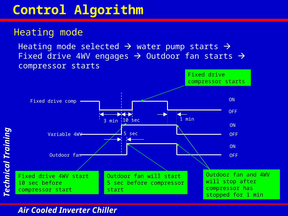
Heating mode selected water pump starts Variable drive 4WV engages Outdoor fan starts compressor starts
Heating mode
Rated Freq.
45Hz
5Hz
t
3 min 10 sec 1 min
ONOFF
ONOFF
Variable drive comp
Outdoor fan
ONOFFVariable 4WV
5 sec Outdoor fan will start 5 sec before compressor start
Variable drive 4WV start 10 sec before compressor start
Inverter compressor will start from 5Hz to 45Hz and maintain this frequency for 1 min.
Increase to rated frequency with the rate of 1Hz/s
5ACV100CR=65Hz5ACV135CR=90Hz
Control Algorithm

Te
chn
ica
l Tra
inin
gT
ech
nic
al T
rain
ing
Air Cooled Inverter ChillerAir Cooled Inverter Chiller
Heating mode
Shut down condition :
• Heating mode terminates, OR
• T set - T water return -2°C
• Variable drive system error occurs, OR
For example :Set temp = 40°CWater return temp = 42°CT = -2°C
Control Algorithm

Te
chn
ica
l Tra
inin
gT
ech
nic
al T
rain
ing
Air Cooled Inverter ChillerAir Cooled Inverter Chiller
Fixed Drive Compressor Control
Cooling mode
Start up condition :
• Pump runs normally for 2 minutes *
• T water return – T set > 4°C
• No irreversible errors in fixed drive and the systems• Satisfy a delay of 3 minutes before restart #
Note : If variable drive system starts first, the fixed drive system will only start after the frequency of variable drive drops to 50Hz.
* Depends on Parameter P2 (flow switch alarm delay at pump start. Min 0s, max 199s, default 120s )# Depends on Parameter C2 (compressor min stop time. Min 0s, max 1990s, default 180s)
For example :Water return temp = 16°CSet temp = 12°CT = 4°C
Fixed drive starts first followed by variable drive
Control Algorithm

Te
chn
ica
l Tra
inin
gT
ech
nic
al T
rain
ing
Air Cooled Inverter ChillerAir Cooled Inverter Chiller
Cooling modeCooling mode selected water pump starts Outdoor fan starts compressor starts
Outdoor fan will start 5 sec before compressor start
Fixed drive compressor starts
Fixed drive comp
Outdoor fan
1 min3 min 5 sec
ON
OFF
ON
OFF
Outdoor fan will stop after compressor has stopped for 1 min
Control Algorithm

Te
chn
ica
l Tra
inin
gT
ech
nic
al T
rain
ing
Air Cooled Inverter ChillerAir Cooled Inverter Chiller
Cooling mode
Shut down condition :
• Cooling mode terminates, OR
• T set - T water return > 2°C and variable frequency drops pass 20Hz
• Fixed drive system error occurs, OR
For example :Set temp = 12°CWater return temp = 10°CT = 2°C
Control Algorithm

Te
chn
ica
l Tra
inin
gT
ech
nic
al T
rain
ing
Air Cooled Inverter ChillerAir Cooled Inverter Chiller
Heating mode
Start up condition :
• Pump runs normally for 2 minutes *
• T set - T water return > 4°C
• No irreversible errors in fixed drive and the systems• Satisfy a delay of 3 minutes before restart #
Note : If variable drive system starts first, the fixed drive system will start after the variable drive frequency drops to 50Hz.
* Depends on Parameter P2 (flow switch alarm delay at pump start. Min 0s, max 199s, default 120s )# Depends on Parameter C2 (compressor min stop time. Min 0s, max 1990s, default 180s)
For example :Set temp = 40°CWater return temp = 36°CT = 4°C
Control Algorithm
Te
chn
ica
l Tra
inin
gT
ech
nic
al T
rain
ing
Air Cooled Inverter ChillerAir Cooled Inverter Chiller
Heating mode selected water pump starts Fixed drive 4WV engages Outdoor fan starts compressor starts
Heating mode
Outdoor fan will start 5 sec before compressor start
Fixed drive 4WV start 10 sec before compressor start
3 min 10 sec 1 min
ON
OFF
ON
OFF
Fixed drive comp
Outdoor fan
ON
OFFVariable 4WV 5 sec
Fixed drive compressor starts
Outdoor fan and 4WV will stop after compressor has stopped for 1 min
Control Algorithm

Te
chn
ica
l Tra
inin
gT
ech
nic
al T
rain
ing
Air Cooled Inverter ChillerAir Cooled Inverter Chiller
Heating mode
Shut down condition :
• Heating mode terminates, OR
• T water return - T set > 2°C
• Fixed drive system error occurs, OR
For example :Water return temp = 42°CSet temp = 40°CT = 2°C
Control Algorithm

Te
chn
ica
l Tra
inin
gT
ech
nic
al T
rain
ing
Air Cooled Inverter ChillerAir Cooled Inverter Chiller
Pump Control
Pump start up
When starting the system, pump will run for 2 minutes * before proceeding to next step.
* Depends on Parameter P2 (flow switch alarm delay at pump start. Min = 0s, Max = 199s, default = 120s)
Pump shut down
After both compressors shut down for 1 minute, pump shuts down.
Control Algorithm

Te
chn
ica
l Tra
inin
gT
ech
nic
al T
rain
ing
Air Cooled Inverter ChillerAir Cooled Inverter Chiller
System error
When errors occur in the system and require system to shut down, the pump will shut down 1 minute after the system shuts down. If compressor is not running, the pump shuts down immediately.
Pump Control
Note : When changing operating mode or when temperature reaches setting, pump continues to run.
Control Algorithm

Te
chn
ica
l Tra
inin
gT
ech
nic
al T
rain
ing
Air Cooled Inverter ChillerAir Cooled Inverter Chiller
Start up conditions• System in heating mode AND• System no error alarm AND• After heating starts for 1 hour and T set – T water return > 5°C The second time start up is not time –dependent.
Auxiliary heater control (Info only)
Heating No error
Running 1 hour T>5°C
For example:Set temp = 40°CWater return temp = 34°C T = 6°C
Switch off conditions
• System terminates heating mode OR• Wired handset withdraws auxiliary heating command, OR• System errors trigger alarm and require shut down, OR• When T set – T water return < 2°C
Heating Error
T< 2°CX
Control Algorithm

Te
chn
ica
l Tra
inin
gT
ech
nic
al T
rain
ing
Air Cooled Inverter ChillerAir Cooled Inverter Chiller
• When system operates for the first time, EXV will operate to preset openings.
• After system operates for 10 minutes, the EXV will preset to superheat regulation for variable drive system.
EXV control (Electronic expansion valve)
Control Algorithm

Te
chn
ica
l Tra
inin
gT
ech
nic
al T
rain
ing
Air Cooled Inverter ChillerAir Cooled Inverter Chiller
• When selecting heating mode, 4 way valve will engage 5 seconds before heating start up. • When heating stops, 4 way valve will disengage 60 seconds after compressor stops.
4 way reversible valve control
• Fixed drive compressor crankcase heater is driven by the fixed drive contactor (NC). • Variable drive compressor crankcase heater is driven by main board relay.• Crankcase heater will be ON whenever compressors are not in operation.
Compressor crankcase heater control
Heating starts4 WV engage 5 sec Select heating mode
compressor stops
4 WV disengage 60 sec Stop heating mode
Control Algorithm
Te
chn
ica
l Tra
inin
gT
ech
nic
al T
rain
ing
Air Cooled Inverter ChillerAir Cooled Inverter Chiller
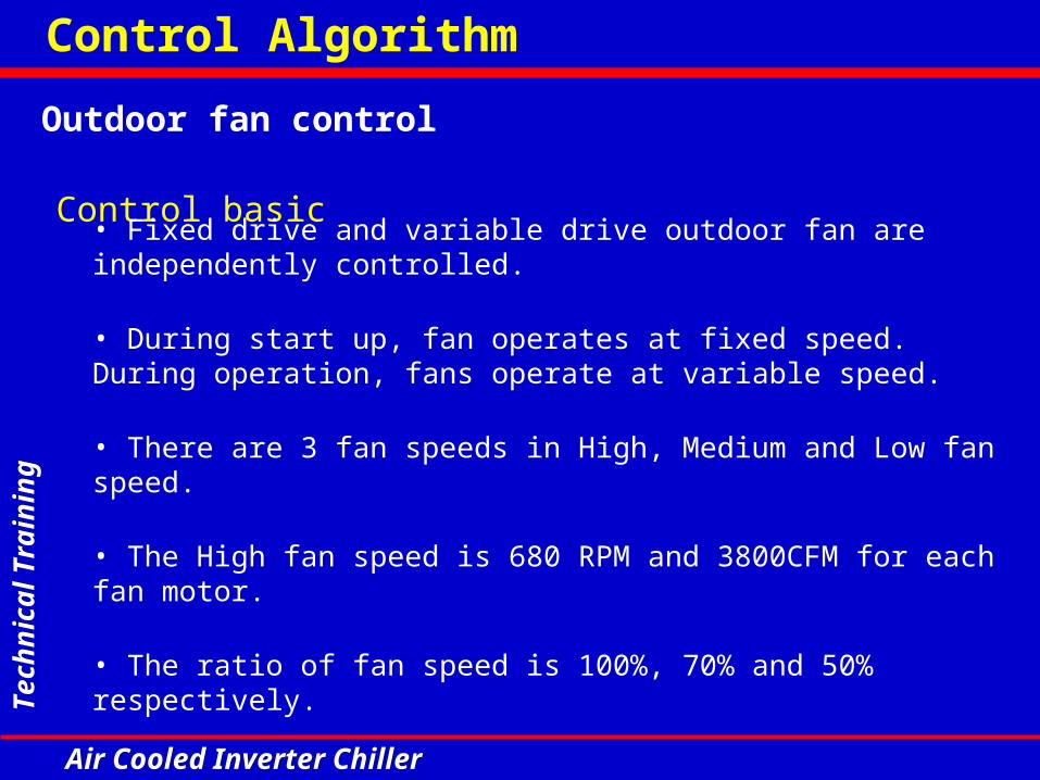
Outdoor fan control
Control basic
• Fixed drive and variable drive outdoor fan are independently controlled.
• During start up, fan operates at fixed speed. During operation, fans operate at variable speed.
• There are 3 fan speeds in High, Medium and Low fan speed.
• The High fan speed is 680 RPM and 3800CFM for each fan motor.
• The ratio of fan speed is 100%, 70% and 50% respectively.
Control Algorithm

Te
chn
ica
l Tra
inin
gT
ech
nic
al T
rain
ing
Air Cooled Inverter ChillerAir Cooled Inverter Chiller
Outdoor fan control
Fan control for Cooling• Within 20 minutes of normal operation, when Te (Outdoor ambient temp.) 28°C, fan operates at highest speed.• Within 20 minutes of normal operation, when Te (Outdoor ambient temp.) <28°C, fan operates at medium fan.• After normal operation for 20 minutes, when 40°C < (Ta3, Tb2) < 48°C, the fan operates to variable speed (PI regulation). The lower the temperature the lower the speed.
48°C
40°C
Constant fan speed control zone
Te 28°C (High fan)Te < 28°C (Med fan)
20 min
High fan zone
PI control zone
Low fan zone
Ta3, Tb2
Ta3 = condenser outlet temp. (Variable drive system)
Tb2 = condenser outlet temp. (Fixed drive system)
PI = program intelligent
Control Algorithm

Te
chn
ica
l Tra
inin
gT
ech
nic
al T
rain
ing
Air Cooled Inverter ChillerAir Cooled Inverter Chiller
Outdoor fan control
Fan control for Heating• When Te (Outdoor ambient temp.) < 10°C, fan operates at highest speed.
• When 10°C Te (Outdoor ambient temp.) 12°C, fan operates at medium fan.• When Te (Outdoor ambient temp.) > 12°C, fan operates at variable speed to PI regulation. The higher the temperature the lower the speed.
12°C
10°C
Low fan
PI control
Constant fan speed control zone (medium fan)
Constant fan speed control zone (high fan)High fan High fan
t
Te
PI=program intelligent
Control Algorithm

Te
chn
ica
l Tra
inin
gT
ech
nic
al T
rain
ing
Air Cooled Inverter ChillerAir Cooled Inverter Chiller
Outdoor fan control
Fan operation during defrosting
Defrost start Defrost end
Variable drive comp
Variable 4WV
Outdoor fan
30 Hz 30 Hz
70 Hz
Resume heating mode
Fan stops 1 minute after the compressor stops.
Control Algorithm

Te
chn
ica
l Tra
inin
gT
ech
nic
al T
rain
ing
Air Cooled Inverter ChillerAir Cooled Inverter Chiller
Anti freeze heater control
Anti freeze on/off control during system standby
• Runs when system in standby mode• If Te (outdoor ambient temperature) 5°C and T water return 5°C, water pump runs 5 minutes every hour and antifreeze heater will run on and off together with the water pump.• If T water return > 6°C water pump and antifreeze heater will stop.• If Te 2°C and T water return 2°C, system enters heating mode and returns to standby when T water return > 30°C
Water return temperature/Outdoor ambient temperature
°C52 6 30
Water pump
Antifreeze heater
ON
ON
System enters heating mode
Run 5 min/hr
Control Algorithm
Te
chn
ica
l Tra
inin
gT
ech
nic
al T
rain
ing
Air Cooled Inverter ChillerAir Cooled Inverter Chiller
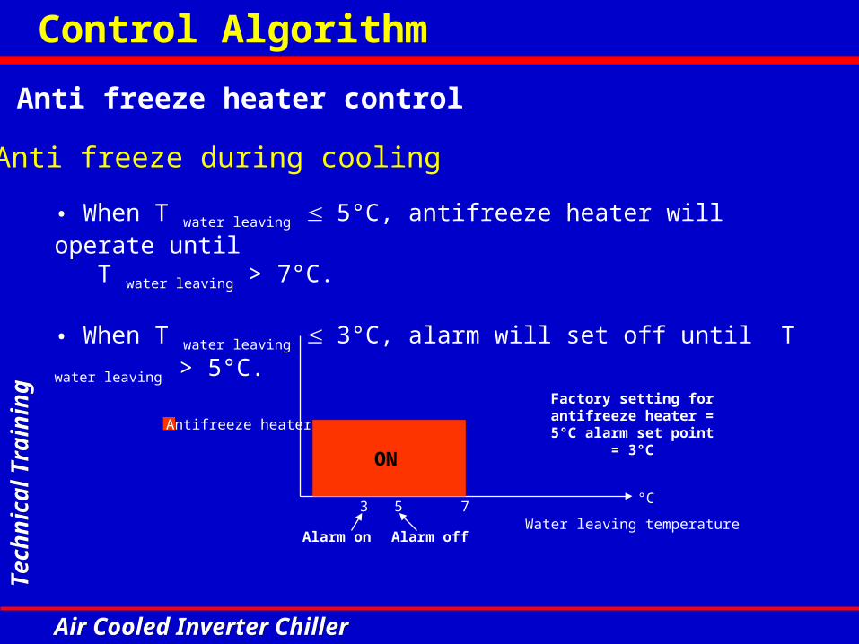
Anti freeze heater control
Anti freeze during cooling
• When T water leaving 5°C, antifreeze heater will operate until T water leaving > 7°C.
• When T water leaving 3°C, alarm will set off until T water leaving > 5°C.
Water leaving temperature
°C53 7
Antifreeze heater
ON
Alarm on Alarm off
Factory setting for antifreeze heater = 5°C alarm set point = 3°C
Control Algorithm

Te
chn
ica
l Tra
inin
gT
ech
nic
al T
rain
ing
Air Cooled Inverter ChillerAir Cooled Inverter Chiller
Defrosting control
Automatic defrostingShall satisfying the below automatic defrosting condition for 3 minutes :• Compressor operates continuously for at least the duration of the defrosting interval. • When Ta3 or Tb2 0°C * OR• When T water return > 18°C
* Depends on Parameter D1 (Start defrost temperature. Min -20°C, max 14°C, default 0°C )Note : Factory defrost interval depends on Parameter D4 (Defrost interval time). Intelligent defrost interval varies. Under Parameter defrost mode, Intelligent defrost is set as default under DISABLE mode. Factory standard defrost will be activated when the parameter is set to ENABLE.
Ta3 = condenser outlet temp. (Variable drive system) Tb2 = condenser outlet temp. (Fixed drive system)
Manual defrosting
Manual defrosting can be carried out when Ta3 or Tb2 < 7°C
Control Algorithm

Te
chn
ica
l Tra
inin
gT
ech
nic
al T
rain
ing
Air Cooled Inverter ChillerAir Cooled Inverter Chiller
Defrosting controlDefrosting processVariable drive defrosting process
• When defrosting conditions are met for variable drive, variable drive compressor stops outdoor fan stops 4WV disengages variable drive starts defrost at 90Hz.• When variable drive defrosting terminates, variable drive compressor stops 4WV engages outdoor fan starts variable drive compressor starts Resume heating operation.
Defrost start Defrost end
Variable drive comp
Variable 4WV
Outdoor fan
30 Hz 30 Hz
90 Hz
Resume heating mode
ONOFF
ONOFF
Control Algorithm

Te
chn
ica
l Tra
inin
gT
ech
nic
al T
rain
ing
Air Cooled Inverter ChillerAir Cooled Inverter Chiller
Defrosting controlDefrosting processFixed drive defrosting process
• When defrosting conditions are met for fixed drive, fixed drive compressor stops (15 sec) outdoor fan stops (2 sec) 4WV disengages (10 sec) fixed drive compressor starts defrost• When fixed drive defrosting terminates, fixed drive compressor stops outdoor fan starts at high speed for 30 sec 4 WV engages Fixed drive compressor starts Resume heating operation.
Defrost start Defrost end
Fixed drive comp
Outdoor fan
4WV
Resume heating mode
ONOFF
ONOFF
15 sec 10 sec
2 sec
10 sec
2 sec 2 sec
ONOFF
Control Algorithm

Te
chn
ica
l Tra
inin
gT
ech
nic
al T
rain
ing
Air Cooled Inverter ChillerAir Cooled Inverter Chiller
Defrosting control
Defrosting process
• As the outdoor fan ducts are independent, defrosting is independent, system restricts defrosting of fixed drive and variable drive at the same time.
• When either variable or fixed drive high pressure protection is triggered, compressor will stop.
• During defrosting, low pressure operation will not trigger protection.
Control Algorithm
Te
chn
ica
l Tra
inin
gT
ech
nic
al T
rain
ing
Air Cooled Inverter ChillerAir Cooled Inverter Chiller
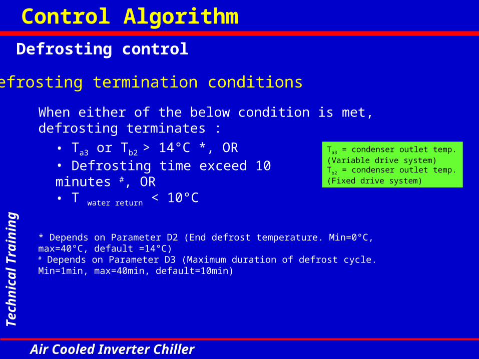
Defrosting control
Defrosting termination conditions
When either of the below condition is met, defrosting terminates :
• Ta3 or Tb2 > 14°C *, OR• Defrosting time exceed 10 minutes #, OR• T water return < 10°C
* Depends on Parameter D2 (End defrost temperature. Min=0°C, max=40°C, default =14°C)# Depends on Parameter D3 (Maximum duration of defrost cycle. Min=1min, max=40min, default=10min)
Ta3 = condenser outlet temp. (Variable drive system) Tb2 = condenser outlet temp. (Fixed drive system)
Control Algorithm

Te
chn
ica
l Tra
inin
gT
ech
nic
al T
rain
ing
Air Cooled Inverter ChillerAir Cooled Inverter Chiller
Defrosting control
Defrosting cycle self-adaptive adjustmentThe next defrosting cycle depends on that of the previous.
1. Defrosting time < 2 minutes, next cycle 120 minutes2. Defrosting time 2 to 4 minutes, next cycle 80 minutes3. Defrosting time 4 to 6 minutes, next cycle 60 minutes4. Defrosting time 6 to 8 minutes, next cycle 40 minutes5. Defrosting time > 8 minutes, next cycle 30 minutes
120 min< 2 min
80 min2 – 4 min
60 min4 – 6 min
40 min6 – 8 min
30 min> 8 min
Control Algorithm

Te
chn
ica
l Tra
inin
gT
ech
nic
al T
rain
ing
Air Cooled Inverter ChillerAir Cooled Inverter Chiller
Control system protectionCompressor over-current protection
Variable drive compressor • When variable drive compressor current reaches the maximum limit, over-current protection triggers and the compressor frequency will reduce.• When the compressor current drops below the limit, frequency variation resumes.• When compressor current increase rapidly and reaches the maximum limit, the system will be determined as compressor overload and stop the compressor. 20.5
17
Variable compressor stops
Maintain frequency
Normal Operation
Comp amp (A)
18Frequency step down
Control Algorithm

Te
chn
ica
l Tra
inin
gT
ech
nic
al T
rain
ing
Air Cooled Inverter ChillerAir Cooled Inverter Chiller
Control system protectionHigh discharge temperature protection
Variable drive system• When variable drive discharge temperature reaches 110°C, system stops.• When variable drive discharge temp. between 100°C and 110°C, frequency drops.• When variable drive discharge temperature is less than 97°C and more than 100°C, frequency increased restricted.• When discharge temperature falls below 94°C, normal operation resumes.
System shuts down
Frequency step down
Maintain frequency
Normal operation
Compressor dischargetemperature
110°C
100°C
97°C94°C
Control Algorithm

Te
chn
ica
l Tra
inin
gT
ech
nic
al T
rain
ing
Air Cooled Inverter ChillerAir Cooled Inverter Chiller
Control system protectionHigh discharge temperature protection
Fixed drive system• When fixed drive discharge temperature reaches 110°C, system stops.• When discharge temperature falls below 94°C for 3 minutes, system resumes.
Td = Compressor discharge temperature
110°C
94°C Comp start
Comp Cut
3 min
Td
Control Algorithm

Te
chn
ica
l Tra
inin
gT
ech
nic
al T
rain
ing
Air Cooled Inverter ChillerAir Cooled Inverter Chiller
Control system protectionOutdoor coil high temperature protection
Variable drive system• During cooling, when Tcoil1 > 60 °C, frequency drops.• During cooling, when Tcoil1 < 55 °C, system resumes.
Fixed drive system• During cooling, when Tcoil2 > 64°C, compressor stops.• During cooling, when Tcoil2 < 51°C, system resumes.
Control Algorithm

Te
chn
ica
l Tra
inin
gT
ech
nic
al T
rain
ing
Air Cooled Inverter ChillerAir Cooled Inverter Chiller
Control system protectionLow pressure switch protection
• Alarm delayed at compressor startup : 30 sec depends on Parameter P3*.• No protection during defrosting.• If variable drive or fixed drive low pressure switch is activated for 5 seconds, alarm will be triggered.* Parameter P3 (Low pressure alarm delay at compressor start up. Min=0s, max=199s, default=30s)
Note : If low pressure alarm occur more than 3 times within 30 minutes, system shuts down to irreversible error.
Control Algorithm

Te
chn
ica
l Tra
inin
gT
ech
nic
al T
rain
ing
Air Cooled Inverter ChillerAir Cooled Inverter Chiller
Control system protection
High pressure switch protection
• If fixed drive high pressure switch is activated for 30 sec, alarm will be triggered.• If variable drive high pressure switch is activated, frequency of variable drive compressor will decrease at 1Hz/s. If it is re-activated for 30 sec, alarm will be triggered.
Note : If high pressure alarm occur more than 3 times within 30 minutes, system shuts down to irreversible error.
Control Algorithm

Te
chn
ica
l Tra
inin
gT
ech
nic
al T
rain
ing
Air Cooled Inverter ChillerAir Cooled Inverter Chiller
Control system protection
3 phase AC phase sequence protection
If 3 phase AC phase sequence is incorrectly connected, system will not start and controller will indicate error. System will resume after rectification.
3 phase AC phase missing protection
If phase missing happens, system will not operate. Controller will indicate error. System will resume after rectification.
Control Algorithm

Te
chn
ica
l Tra
inin
gT
ech
nic
al T
rain
ing
Air Cooled Inverter ChillerAir Cooled Inverter Chiller
Chiller Panel Controller

Te
chn
ica
l Tra
inin
gT
ech
nic
al T
rain
ing
Air Cooled Inverter ChillerAir Cooled Inverter Chiller
LCD Display
On/Off Indicator
Navigation Key (Up &
Down)
Cancel Instruction Key
Execute Instruction Key
Switching Heat Mode
Switching Cool Mode
Show Alarm Key
On/Off Shortcut Key
Short cut key can only be used in the summary page!
Short cut key Navigation key
Chiller Panel Controller

Te
chn
ica
l Tra
inin
gT
ech
nic
al T
rain
ing
Air Cooled Inverter ChillerAir Cooled Inverter Chiller
Backup Battery
CMOS Reset Jumper (JH2)
Chiller Terminal Unit Connection
(CN8)
+12Vdc, GND; A, B
Reset some of the settings to the
DEFAULT value
Memorize of Date, Time & Timer
Schedule
Chiller Panel Controller

Te
chn
ica
l Tra
inin
gT
ech
nic
al T
rain
ing
Air Cooled Inverter ChillerAir Cooled Inverter Chiller
Menu structure
Summary Pages
Main Menu
Unit Selection Menu
Operation Menu
Settings Menu
Timer Menu
Alarm Menu
Display Menu
Status
Mode
Cool Set
Heat Set
Manual Defrost
Set Parameter [#]
Change Password [#]
Panel Option
Set Panel ID
Clock Setting
Date Setting
Time Schedule
Timer
Show Alarms
Erase All Alarms
Defrost Sensor
Discharge Sensor
Comp Run Time [#]
Inverter Chiller
General
Regulator
Compressor
Defrost
Antifreeze
Inverter
Alarm and Contact
Chiller Panel Controller

Te
chn
ica
l Tra
inin
gT
ech
nic
al T
rain
ing
Air Cooled Inverter ChillerAir Cooled Inverter Chiller
Setting menu
Setting parameter for Inverter
Inverter parameter setting page on the chiller panel controller
SETTINGS MENU
Set Parameter
Change Password
Panel Option
Set Panel ID
1. General
2. Regulator
3. Compressor
4. Condenser Defrost
5. Cool Mode Antifreeze
6. Inverter
7. Alarm & Contact
V1 Cp Freq : 0Hz
V2 EXV : 0
V3 Cp Manual : Disable
V4 EXV Manual : Disable
V5 Def Mode : Disable
Chiller Panel Controller

Te
chn
ica
l Tra
inin
gT
ech
nic
al T
rain
ing
Air Cooled Inverter ChillerAir Cooled Inverter Chiller
V1 : Compressor frequency It allows to set the inverter compressor frequency (max frequency varies according to models)V2 : EXV (Electronic expansion valve) It allows to set the EXV opening (0-480 pulsation)
INVERTER Unit Default Min Max ResolutionV1 Compressor frequency Hz Auto 0 120 1V2 EXV Opening Flag Auto 0 480 1
Compressor manual setting Flag 0 (disable) 0 1 10 = disable 1 = enableEXV Manual setting Flag 0 (disable) 0 1 10 = disable 1 = enableDefrost Mode Flag 0 (disable) 0 1 10 = disable 1 = enable
V3
V4
V5
There are 5 setting parameters for Inverter ( V1 to V5 )
V3 : Cp Manual This parameter enable automatic or manual setting for the compressor frequency. ( Enable : manual setting is possible, Disable : frequency auto-run )
Chiller Panel Controller

Te
chn
ica
l Tra
inin
gT
ech
nic
al T
rain
ing
Air Cooled Inverter ChillerAir Cooled Inverter Chiller
INVERTER Unit Default Min Max ResolutionV1 Compressor frequency Hz Auto 0 120 1V2 EXV Opening Flag Auto 0 480 1
Compressor manual setting Flag 0 (disable) 0 1 10 = disable 1 = enableEXV Manual setting Flag 0 (disable) 0 1 10 = disable 1 = enableDefrost Mode Flag 0 (disable) 0 1 10 = disable 1 = enable
V3
V4
V5
V5 : Def Mode This parameter enable automatic intelligent or standard defrosting. ( Enable : manual setting is possible in Parameter D1-D6, Disable : Intelligent defrosting [auto-run] )
V4 : EXV Manual This parameter enable automatic or manual setting for the EXV opening. ( Enable : manual setting is possible, Disable : EXV opening auto-run )
Chiller Panel Controller

Te
chn
ica
l Tra
inin
gT
ech
nic
al T
rain
ing
Air Cooled Inverter ChillerAir Cooled Inverter Chiller
Display menu
Display menu for Inverter
Inverter display menu page on the chiller panel controller
DISPLAY MENU
Defrost Sensor
Discharge Sensor
Comp. Run Time
Inverter Chiller
Inverter Chiller
Comp Freq : 75Hz
EXV : 320
Comp Amp : 9.7A
DC Bus : 555V
Inverter Chiller
Suction : 15.5 °C
BPHE In : 45.9 °C
BPHE Out : 18.3 °C
Condenser : 28.4 °C
Screen 1
Screen 2
Chiller Panel Controller

Te
chn
ica
l Tra
inin
gT
ech
nic
al T
rain
ing
Air Cooled Inverter ChillerAir Cooled Inverter Chiller
Display menu
Display menu for Inverter
Compressor FrequencyIt shows the operating inverter compressor frequency. (Hz)
EXVIt shows the operating EXV opening (pulse).
Comp AmpIt shows the operating inverter compressor running current. (A)
DC BusIt shows the operating DC voltage in the inverter system. (V)
Inverter Chiller
Comp Freq : 75Hz
EXV : 320
Comp Amp : 9.7A
DC Bus : 555V
Chiller Panel Controller

Te
chn
ica
l Tra
inin
gT
ech
nic
al T
rain
ing
Air Cooled Inverter ChillerAir Cooled Inverter Chiller
Display menu
Display menu for Inverter
SuctionIt shows the inverter compressor suction temperature. (°C)
BPHE InIt shows the refrigerant inlet temperature at the BPHE during cooling mode. During heating mode, the value represents the refrigerant outlet temperature at the BPHE. (°C)BPHE OutIt shows the refrigerant outlet temperature at the BPHE during cooling mode. During heating mode, the value represents the refrigerant inlet temperature at the BPHE. (°C)
CondenserIt shows the inverter condenser coil inlet temperature. (°C)
Inverter Chiller
Suction : 15.5 °C
BPHE In : 45.9 °C
BPHE Out : 18.3 °C
Condenser : 28.4 °C
Chiller Panel Controller

Te
chn
ica
l Tra
inin
gT
ech
nic
al T
rain
ing
Air Cooled Inverter ChillerAir Cooled Inverter Chiller
Self Diagnosis & Troubleshooting

Te
chn
ica
l Tra
inin
gT
ech
nic
al T
rain
ing
Air Cooled Inverter ChillerAir Cooled Inverter Chiller
Comp Fan Comp Fan Phase Missing Phase missing Manual OFF OFF OFF OFF OFFPhase Seq Error Wrong phase sequencing Manual OFF OFF OFF OFF OFFMemory Error EEPROM read/write error Auto OFF OFF OFF OFF OFFEntering Water Sensor Open/Short BPHE water in sensor error Auto OFF OFF OFF OFF OFFLeaving Water Sensor Open/Short BPHE water out sensor error Auto OFF OFF OFF OFF OFFOutdoor Air sensor Open/Short Ambient temp sensor error Auto OFF OFF OFF OFF OFFWater Flow Error Cv contact opened Manual OFF OFF OFF OFF OFFCool Mode Antifreeze Leaving water temp. too low Auto OFF OFF OFF OFF OFFOV/UN Voltage Comp. High Voltage (>490V) <460V, Auto OFF OFF OFF OFF OFFOV/UN Voltage Comp. Low Voltage (<310V) >340V, Auto OFF OFF OFF OFF OFFPump Overload Pump OLP opened Auto OFF OFF OFF OFF OFFIPM Error IPM over-current or overheat Auto - OFF OFF - -Comp 1 Overload Comp 1 overload Auto - OFF OFF - -Comp 1 Discharge Overheat Comp 1 discharge Overheat Auto - OFF OFF - -High pressure 1 System 1 high pressure Auto - OFF OFF - -Low pressure 1 System 1 low pressure Auto - OFF OFF - -Comp 1 Defrost sensor Open/Short Coil out system 1 sensor error Auto - OFF OFF - -Comp 1 Suct sensor Open/Short Suction comp system 1 sensor error Auto - OFF OFF - -Comp 1 Discharge sensor Open/Short Discharge comp system 1 sensor error Auto - OFF OFF - -Coil 1 Inlet Temp Open/Short Coil in system 1 sensor error Auto - OFF OFF - -V-Hx Inlet Temp sensor Open/Short BPHE refrigerant in sensor error Auto - OFF OFF - -V-Hx Outlet Temp sensor Open/Short BPHE refrigerant out sensor error Auto - OFF OFF - -Comp 2 Overload Comp 2 overload Auto - - - OFF OFFHigh pressure 2 System 2 high pressure Auto - - - OFF OFFLow pressure 2 System 2 low pressure Auto - - - OFF OFFComp 2 Defrost sensor Open/Short Coil out system 2 sensor error Auto - - - OFF OFFComp 2 Discharge sensor Open/Short/Overheat
Discharge comp system 2 sensor error Auto - - - OFF OFF
Error descriptionError displayPump
Control measureSystem 1
(Variable Drive)System 2
(Fixed drive)Reset
(default)
Error Code
Self Diagnosis & Troubleshooting

Te
chn
ica
l Tra
inin
gT
ech
nic
al T
rain
ing
Air Cooled Inverter ChillerAir Cooled Inverter Chiller
1. No response after power-on
No response
Check Input conditions
Check Input power supply
Check DC rectifier circuit
Is Power board DC-IN voltage normal?
Is LED main board lit?
Is R,S,T Input voltage normal?
Yes
No
Yes
No
No
Is connection between main board and IPM normal?
Main board faulty, To replace.
Main board or IPM short circuit, To replace.
Is JP-power/DC-OUT output normal?
Yes
No
Replace power board components
No
Yes
Yes
JP-power (+12VDC &
+5VDC)
DC-OUT (+15VDC)
Power board
DC-IN (+590VDC)
Self Diagnosis & Troubleshooting

Te
chn
ica
l Tra
inin
gT
ech
nic
al T
rain
ing
Air Cooled Inverter ChillerAir Cooled Inverter Chiller
2. LED on main board normal, but no output.
LED lit, No output
Is output condition ok?
No
Is load ok?
Is main board’s fuse ok?
Replace main board
Rectify
Rectify
Rectify
No
No
Yes
Yes
Self Diagnosis & Troubleshooting

Te
chn
ica
l Tra
inin
gT
ech
nic
al T
rain
ing
Air Cooled Inverter ChillerAir Cooled Inverter Chiller
3. Other functions normal but compressor not functioning
Others OK, Comp not functioning
Is fuse in DC loop ok?
Yes
Is IPM ok?
Is compressor ok?
Change fuse
Check operating conditions
Replace
Replace
No
No
Yes
No
Yes
Self Diagnosis & Troubleshooting

Te
chn
ica
l Tra
inin
gT
ech
nic
al T
rain
ing
Air Cooled Inverter ChillerAir Cooled Inverter Chiller
4. Flow switch protection
Water flow error
Short JK4
Is water flow error persists?
Main board faulty , replace main board
Flow switch faulty or pump stopped.
No
Yes
JK4 on main board
Self Diagnosis & Troubleshooting

Te
chn
ica
l Tra
inin
gT
ech
nic
al T
rain
ing
Air Cooled Inverter ChillerAir Cooled Inverter Chiller
5. Over voltage protection
OV/UN Voltage
Is Power supply < 460VAC?
Power board error, rectify.
RectifyYesIs Power
supply > 490VAC?
No
No
Yes
Self Diagnosis & Troubleshooting

Te
chn
ica
l Tra
inin
gT
ech
nic
al T
rain
ing
Air Cooled Inverter ChillerAir Cooled Inverter Chiller
6. Under voltage protection
OV/UN Voltage
Is Power supply > 340VAC?
Power board error, rectify.
RectifyYesIs Power
supply < 310VAC?
No
No
Yes
Self Diagnosis & Troubleshooting

Te
chn
ica
l Tra
inin
gT
ech
nic
al T
rain
ing
Air Cooled Inverter ChillerAir Cooled Inverter Chiller
7. Pump overload protection
Pump overload
Remove JK8, 97 & 98, is it still conducting?
Pump overload
Main board faulty
NoIs voltage of 97, 98 on heat relay VDC = 0 V
Yes
No
Yes
JK8 on main board
Self Diagnosis & Troubleshooting

Te
chn
ica
l Tra
inin
gT
ech
nic
al T
rain
ing
Air Cooled Inverter ChillerAir Cooled Inverter Chiller
8. Phase missing
Phase missing
Is Voltage between R,S,T
415VAC ±20%?
No
Is J-RST on main board 415VAC ±20%?
Disconnect power, remove J-RST, is voltage of socket 415VAC ±20%?
To Check/replace EMI filter
Check incoming supply
Main board faulty
Yes
No
No
Yes
Yes
3 Phase supply
Self Diagnosis & Troubleshooting

Te
chn
ica
l Tra
inin
gT
ech
nic
al T
rain
ing
Air Cooled Inverter ChillerAir Cooled Inverter Chiller
9. IPM protectionYes
IPM Error
Is IPM temperature >100°C?
Replace
Check compressor
Normal
Rectify
Main board faulty or wrong signal
Is heat sink temperature >100°C?
Is IPM Error persists?
Is IPM ok?
Is current at rated frequency ok?
Yes
No
No
Reapply heat compound
No
Yes
No
No
Yes
No
Is heat compound dried out?
Change IPM
Yes
Yes
Self Diagnosis & Troubleshooting

Te
chn
ica
l Tra
inin
gT
ech
nic
al T
rain
ing
Air Cooled Inverter ChillerAir Cooled Inverter Chiller
10. Variable compressor over-current protection
Comp 1 overload
Main board or compressor faulty
Replace
Comp and current checked, circuit ok.
YesRestart. Set freq. with handset. Check current, is it ok?
No
Self Diagnosis & Troubleshooting

Te
chn
ica
l Tra
inin
gT
ech
nic
al T
rain
ing
Air Cooled Inverter ChillerAir Cooled Inverter Chiller
11. Variable drive high pressure protection
High Pressure 1
Check AC system for overload
Rectify
Replace
NoIs high pressure switch ok?
Yes
Self Diagnosis & Troubleshooting

Te
chn
ica
l Tra
inin
gT
ech
nic
al T
rain
ing
Air Cooled Inverter ChillerAir Cooled Inverter Chiller
12. Variable drive low pressure protection
Low Pressure 1
Check AC system for low pressure
Rectify
Replace
NoIs low pressure switch ok?
Yes
Self Diagnosis & Troubleshooting

Te
chn
ica
l Tra
inin
gT
ech
nic
al T
rain
ing
Air Cooled Inverter ChillerAir Cooled Inverter Chiller
13. Variable compressor high discharge temperature protection
Comp 1 Discharge Overheat
Temp sensor ok? (<100°C?)
Rectify
Compressor stops
Yes> 110 °C ?
No
Check AC system
Replace
Self Diagnosis & Troubleshooting

Te
chn
ica
l Tra
inin
gT
ech
nic
al T
rain
ing
Air Cooled Inverter ChillerAir Cooled Inverter Chiller
14. Fixed compressor over-current protection
Comp 2 Overload
Check on compressor winding resistance, is it to spec ?
No
Check on Compressor insulation, is it ok?
Check current reading on handset against actual reading, is it very big different?
Current sensing circuit error. Replace main board
Rectify
Rectify
NormalNo
Yes
No
Is supply voltage ok? Rectify
No
Yes
Yes
Yes
Self Diagnosis & Troubleshooting

Te
chn
ica
l Tra
inin
gT
ech
nic
al T
rain
ing
Air Cooled Inverter ChillerAir Cooled Inverter Chiller
Installation

Te
chn
ica
l Tra
inin
gT
ech
nic
al T
rain
ing
Air Cooled Inverter ChillerAir Cooled Inverter Chiller
Installation
• Unit Handling
• Unit Placement
• Maintenance Access
• Water Connection
• Power Supply & Electrical Connection
• Piping Cleaning
• Preliminary Checking before Start-up

Te
chn
ica
l Tra
inin
gT
ech
nic
al T
rain
ing
Air Cooled Inverter ChillerAir Cooled Inverter Chiller
Unit Handling
5ACV 100/135/210 CR

Te
chn
ica
l Tra
inin
gT
ech
nic
al T
rain
ing
Air Cooled Inverter ChillerAir Cooled Inverter Chiller
Unit Placement
• Air Cooled Chiller are cooled by air, space restriction will reduces the air flow, decrease the cooling capacity, increase the power input and, in come cases, prevent the unit from operating because of an excess of condensation pressure.
• 5ACV equipped with propeller fan, which doesn’t need ductwork on fan outlet.
• Direct effect of the wind on the discharge surface of the fan should be avoided.
• Enough clearance around the unit for maintenance works.

Te
chn
ica
l Tra
inin
gT
ech
nic
al T
rain
ing
Air Cooled Inverter ChillerAir Cooled Inverter Chiller
Minimum clearances
5ACV100/135CR
5ACV30/55/75CR

Te
chn
ica
l Tra
inin
gT
ech
nic
al T
rain
ing
Air Cooled Inverter ChillerAir Cooled Inverter Chiller

Te
chn
ica
l Tra
inin
gT
ech
nic
al T
rain
ing
Air Cooled Inverter ChillerAir Cooled Inverter Chiller
Maintenance Access
5ACV30/55/75CR

Te
chn
ica
l Tra
inin
gT
ech
nic
al T
rain
ing
Air Cooled Inverter ChillerAir Cooled Inverter Chiller
Maintenance Access
5ACV100/135/210 CR

Te
chn
ica
l Tra
inin
gT
ech
nic
al T
rain
ing
Air Cooled Inverter ChillerAir Cooled Inverter Chiller
Water Piping & Fitting
Install piping with minimum bends and changes in elevation to minimize pressure drop. Consider the following;
!
• Vibration eliminators to reduce vibration and noise transmission to the building.
• Shut off valves to isolate the unit from the piping system during unit servicing.
• Manual or automatic air vent valves at the highest points of the chilled water piping.
• A means of maintaining adequate system water pressure (expansion tank or regulating valve)
• Temperature and pressure indicators located at the unit to air in unit servicing.

Te
chn
ica
l Tra
inin
gT
ech
nic
al T
rain
ing
Air Cooled Inverter ChillerAir Cooled Inverter Chiller
Water connection could be damaged by an excessive stress when screwing them. Use a second spanner to compensate the stress of tightening.
!
Water Piping & Fitting…cont.
• Safety differential pressure switch is used to ensure adequate water flow to evaporator before starting up the unit. • Balancing valve to regulate the amount of water flow rate through the unit.
It is mandatory to install a strainer at the inlet of the unit.!

Te
chn
ica
l Tra
inin
gT
ech
nic
al T
rain
ing
Air Cooled Inverter ChillerAir Cooled Inverter Chiller
Water Piping & Fitting…cont.

Te
chn
ica
l Tra
inin
gT
ech
nic
al T
rain
ing
Air Cooled Inverter ChillerAir Cooled Inverter Chiller
Power Supply & Electrical Connection
Electrical Data

Te
chn
ica
l Tra
inin
gT
ech
nic
al T
rain
ing
Air Cooled Inverter ChillerAir Cooled Inverter Chiller
Power Supply & Electrical Connection…Cont.
Recommended Fuses & Cable Size

Te
chn
ica
l Tra
inin
gT
ech
nic
al T
rain
ing
Air Cooled Inverter ChillerAir Cooled Inverter Chiller
Power Supply & Electrical Connection…Cont.
Before carrying out any operations on the electrical system, make sure that the unit is de-energized.!
It is important that the appliance is grounded.!
Before connecting the power supply lines, check that the available voltage value does not exceed the range specified in the electrical data being provided in Installation Manual.
!
It’s recommended to check the correct sequence of the 3 supply phases R-S-T before the unit start up.!

Te
chn
ica
l Tra
inin
gT
ech
nic
al T
rain
ing
Air Cooled Inverter ChillerAir Cooled Inverter Chiller
• Check the section of power supply and grounding cable.
• Check that any voltage and phase variation in the power supply does not exceed the prefixed thresholds.
• Check that components of the external water circuit (user equipment, filters, power supply tank and reservior, if any) have been installed properly, and according to the manufacturer’s instructions.
• Check that the filling of the hydraulic circuits, and make sure that the fluid circulation is correct, without any trace of leaks and air bubbles.
• Check that the direction of rotation of the pumps is correct.
• Adjust the liquid distribution network in such a way that the flow rate is within the specified range.
• Check that the water quality is up to the specification.
Preliminary Checking before Start-up

Te
chn
ica
l Tra
inin
gT
ech
nic
al T
rain
ing
Air Cooled Inverter ChillerAir Cooled Inverter Chiller
• Run the clean water through the water inlet and operate the pump to drain out the dirty water. Clean the strainer after running the pump for 30 minutes.
• Fill up the water circuit after connecting the pipes and equipment. Check water leakage at all connections and joints. Do not start the unit when the system is leaking.
• To optimize the capacity of the system, ensure that the system is free of air bubbles. The air trapped in the system would make the system unbalanced.
Piping Cleaning

Te
chn
ica
l Tra
inin
gT
ech
nic
al T
rain
ing
Air Cooled Inverter ChillerAir Cooled Inverter Chiller
Thank You