NISSAN LEAF FRENTE AO BMW i3, MITSUBISHI i-MIEV E TESLA MODEL S P85 NA "AUTO FOCO"
Air-Conditioning system
For Electric Vehicles
(i-MiEV)
Presented by
Kohei Umezu
Mitsubishi Motors Corporation
Hideto Noyama
Mitsubishi Heavy Industries, Ltd.
SAE Automotive Refrigerant & System Efficiency Symposium 2010
1.Introducing Mitsubishi Electric Vehicle, “i-MiEV”
2.Outline of the AC system2.1 Concept of the system
2.2 Actual Configuration of the system
2.3 Specification of key components
2.4 Control specification
3.Performance3.1 Vehicle test results (Cooling performance)
3.2 Vehicle test results (Heating performance)
3.3 Electric Power consumption
4.Summary
5.Next step – future development
Contents

1. Introducing “i-MiEV” (1)
Mitsubishi Motors Corporation (MMC) recently developed “i-MiEV”
as an electric vehicle utilizing the ultimate eco-friendly zero-emission
driving based on the “i” mini car.
“i-MiEV” is the reconstructed
electric vehicle adopting
revolutionary technology such as
high-performance lithium-ion
batteries and compact high
performance motors.
“i-MiEV” vehicles are currently in service throughout Japan via
joint MMC - Power Company cooperative fleet testing.
Fig. 1.1 Mitsubishi “i-MiEV”

1. Introducing “i-MiEV” (2)
Basic configuration and major specifications of the vehicle are
shown as follows.
L * W * H 3,395 * 1,475 * 1,600 (mm)
Wheelbase 2,550 mm
Mass 1,080 kg
N of Passengers 4
Max Speed 130 km/h
Range/charge 160 km (100mile)
Motor 47kW, 180Nm
Drive Rear Wheel Drive
Battery Lithium-ion, 330V, 16Wh
The vehicle has sufficient driving
performance and cruising range
for normal customer usage
(160km/100mile).
Power source Charge duration
Quick charge
3 phase 200V50kW
within 30 min.
Regular charge
200V (15A) about 7 hrs
100V (15A) about 14 hrs
Table 1.1 Major specifications of i-MiEV
Fig. 1.2 Vehicle configuration Table 1.2 Charging performance
Regular charge plugInverter On-board
charger
Lithium-ion batterysystem
Motor Quick chargerplug

1. Introducing “i-MiEV” (3)
Motor
000
CombinationMeter
BMU
PRNDEcoB
Vehicle-CAN
Quick charging connection
Regular charging connection
EMCU
CMU
DCDC
OBC
Heater
Battery
Module
Trans mission
EV-
ECU
A/C COMP
A/C ECU
Main Battery
Fig. 1.3 Vehicle system configuration

2. Outline of the AC system (1)
2.1 Concept of the systemBasic concept of the AC system for “i-MiEV” is to appropriate
original vehicle’s system to the vehicle due to cost reduction in
both development and parts.
Features:
The system has a refrigerant
cycle with a Electric driven
compressor for cooling and a
coolant cycle with a PTC
Heater for heating.
Motor
Cond.
Fan M
odule
Evap.
Rad.
Htr
.H
tr.
Motor
HVAC Module
CoolantPTCHeater
Electric driven Compressor
CoolantPump
Coolantcondensing Tank
Condenser
CoolantCycle
RefrigerantCycle
Fig. 2.1 AC system configuration
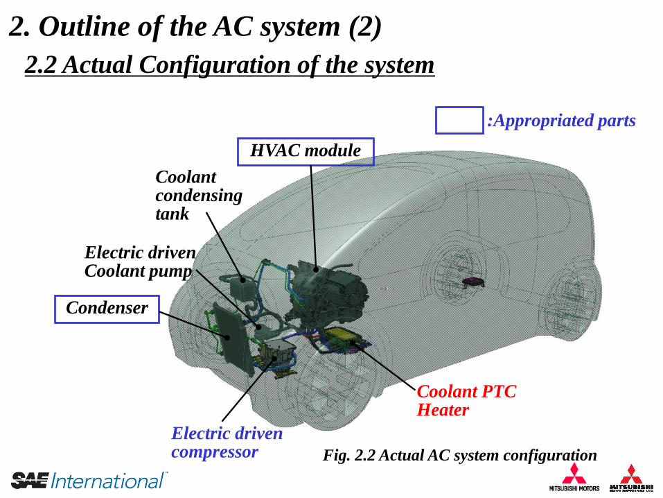
2. Outline of the AC system (2)
2.2 Actual Configuration of the system
HVAC module
Coolant condensing tank
Electric drivenCoolant pump
Condenser
Electric driven compressor
Coolant PTC Heater
Fig. 2.2 Actual AC system configuration
:Appropriated parts

2. Outline of the AC system (3)
2.3 Specification of key components(1) Electric driven compressor
L * W * H 291 * 162 * 157 (mm)
Mass 10.2kg (with Bracket)
Compressor type Scroll with rare earth metal motor
Displacement 30 cc/rev.
Inverter Integrated,suction ref. cooling
Max. rev. 6000 rpm
High Voltage range DC 220 ~ 400 V
Low Voltage range DC 8 ~ 16 V
Max. power 4.5 kW
Max. input current 20.5 A (@DC 220V)
Refrigerant HFC-134a
Ref. Lubricant POE oil
Table 2.1 Electric driven compressor spec.
Fig. 2.3 Electric driven compressor
Oil separator is integrated
due to improvement of both
ref cycle capacity and
efficiency.
Scroll compressor
part
Control part(Inverter)
Rare earthmetal motor part

2. Outline of the AC system (4)
(2)-1 Coolant PTC Heater
L * W * H 290 * 160 * 100 (mm)
Mass 7.4 kg (dry)
Heating devices PTC heating elements
Heating Capacity 5.0 kW (@ 6L/min., 25 deg C)
Coolant press. Drop 2 kPa (@ 6L/min., 80 deg C)
Capacity control On/Off cycling(8 steps)
High Voltage range DC 220 ~ 400 V
Low Voltage range DC 8 ~ 16 V
Table 2.2 Coolant PTC Heater spec.
PTC: Positive Temperature Coefficient
Fig. 2.4 Coolant PTC Heater
The heater is installed in
vehicle under hood area.
Therefore the high voltage
cable doesn’t need to be
leaded into the cabin.
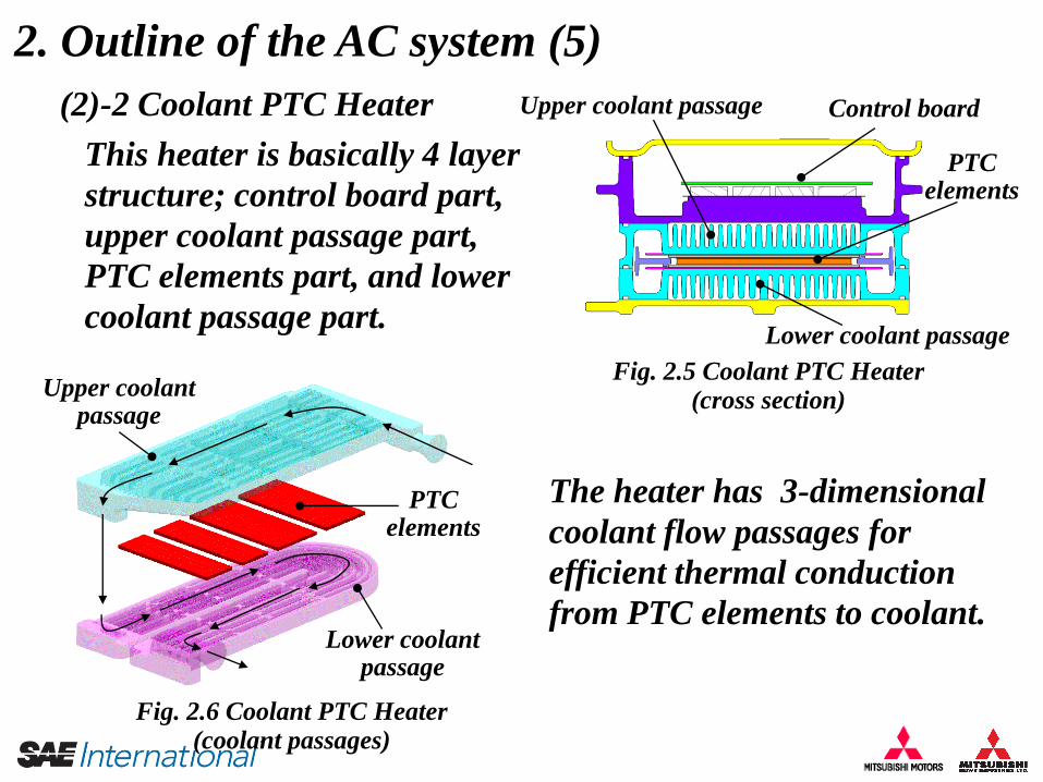
2. Outline of the AC system (5)
(2)-2 Coolant PTC Heater
Fig. 2.5 Coolant PTC Heater(cross section)
The heater has 3-dimensional
coolant flow passages for
efficient thermal conduction
from PTC elements to coolant.
This heater is basically 4 layer
structure; control board part,
upper coolant passage part,
PTC elements part, and lower
coolant passage part.
Fig. 2.6 Coolant PTC Heater(coolant passages)
Control board
PTCelements
Lower coolant passage
Upper coolant passage
Upper coolantpassage
Lower coolantpassage
PTCelements

2. Outline of the AC system (6)
(2) MAX switch (SW)
2.4 Control specification
Fig. 2.7 Control Panel (1)
(2) MAX SW(1) Temperature control
(1) Temperature control
There are 6 positions of “Cool”,6
positions of “Hot”, and “Ventilation”
position. This control decrease the
situation in which both the compressor
and the PTC heater are operated
simultaneously.
MAX SW ON:
The system is operated under
maximum capacity.
⇒ Usually “OFF”
MAX SW OFF:
Fan speed and coolant temp
are limited.

2. Outline of the AC system (7)
(4) Ventilation position
Fig. 2.7 Control Panel (2)
(4)Ventilation position(3) Fan Auto position
(3) Fan auto controlFan speed is controlled automatically
to keep comfort temp in the cabin.
Both the compressor and the PTC
heater are off. Only fan is operated
for ventilation.

0
10
20
30
40
50
60
0 30 60Time [min]
Tem
p. [d
egC
]3. Performance (1)
3.1 Vehicle test results (Cooling performance)
Ambient Temp : 35 degC (50%RH)
Sun Load : 850 W/m2
40km/h
Fig. 3.1 Cooling Performance
Idling
Room Temp.
Vent. OutletTemp.
ii-MiEV
The cooling performance of “i-MiEV” is slightly better than that of the baseline vehicle “i”.
80km/h
MAX SW : ON
-20
0
20
40
60
80
100
0 15 30 45 60Time [min]
Tem
p. [d
egC
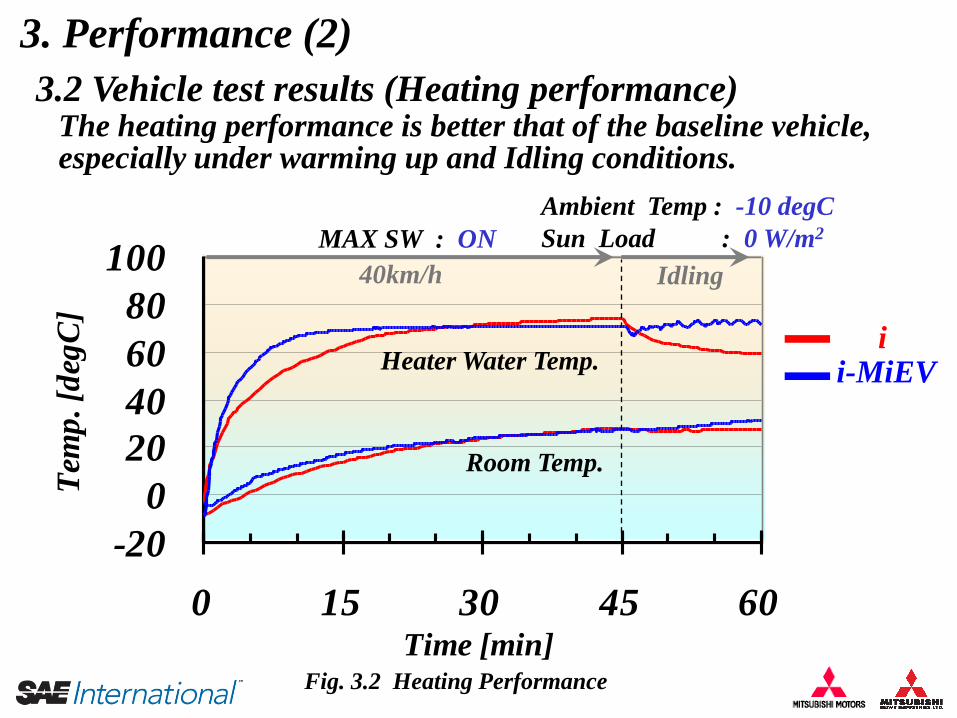
]3. Performance (2)
3.2 Vehicle test results (Heating performance)
Ambient Temp : -10 degC
Sun Load : 0 W/m2
40km/h
Fig. 3.2 Heating Performance
Idling
Room Temp.
Heater Water Temp.
The heating performance is better that of the baseline vehicle, especially under warming up and Idling conditions.
ii-MiEV
MAX SW : ON

3. Performance (3)
3.3 Electric Power consumption (1) Power consumption
Power consumption [kWh]
AC MAX_SW ON
Motor Power
AC&Heater
Power
MAX_SW OFF
MAX_SW OFF
(50%)
Fig. 3.3 Power consumption
Heater MAX_SW ON
Driving pattern: 10-15 mode
Large electric power is necessarywhen heater is operated.
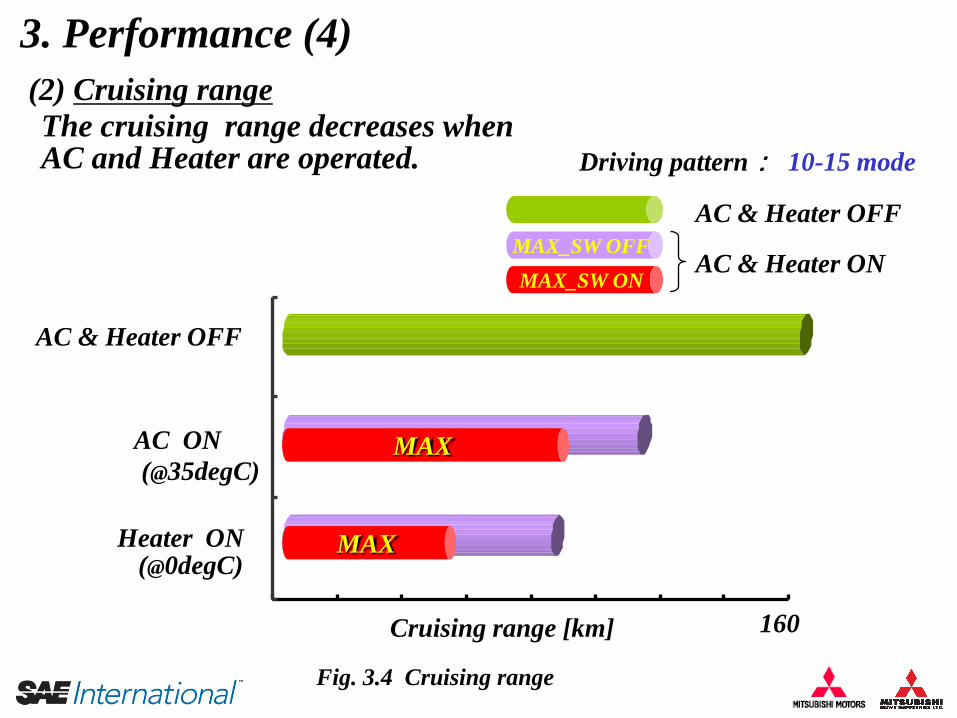
3. Performance (4)
(2) Cruising range
Fig. 3.4 Cruising range
Driving pattern: 10-15 mode
MAX_SW OFF
MAX
MAX
MAX_SW ON
160Cruising range [km]
AC & Heater ON
AC & Heater OFF
AC & Heater OFF
AC ON
Heater ON
(@35degC)
(@0degC)
The cruising range decreases when AC and Heater are operated.
4. Summary
• Mitsubishi Motors have developed the Air-Conditioning system
for Electric Vehicle “i-MiEV” with a electric driven compressor
and coolant PTC heater as key components.
• The cooling/heating performance of the vehicle is almost equal to
the baseline “i”, which is a conventional engine vehicle, under
normal usage conditions.
• Operating the AC system have influence on the cruising rage of
the vehicle, especially under heating mode.
5. Next Step – future development (1)
• Improve cruising range by decreasing AC system power
consumption during vehicle driving. – Decreasing vehicle thermal load (including “Pre AC” during charging)
– Improving the efficiency of the AC system
etc.
• Improve power consumption of coolant PTC heater, especially.
– Reducing size and mass
–Improving control and efficiency
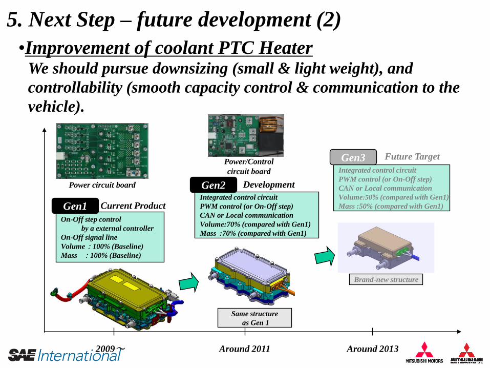
5. Next Step – future development (2)
•Improvement of coolant PTC HeaterWe should pursue downsizing (small & light weight), and
controllability (smooth capacity control & communication to the
vehicle).
Integrated control circuit
PWM control (or On-Off step)
CAN or Local communication
Volume:50% (compared with Gen1)
Mass :50% (compared with Gen1)
On-Off step control
by a external controller
On-Off signal line
Volume:100% (Baseline)
Mass :100% (Baseline)
Integrated control circuit
PWM control (or On-Off step)
CAN or Local communication
Volume:70% (compared with Gen1)
Mass :70% (compared with Gen1)
Gen1
Gen2
Gen3
Current Product
Development
Future Target
2009~ Around 2011 Around 2013
Power circuit board
Same structure
as Gen 1
Brand-new structure
Power/Control
circuit board
Thank you for your attention.
END