Air conditioning diagnosis service and repair v2
100
Air Conditioning Diagnosis, Service & Repair
Transcript of Air conditioning diagnosis service and repair v2

Air Conditioning
Diagnosis,
Service & Repair

Copyright © 2011 Standard Motor Products, Inc. All Rights reserved.
2
Portions of this manual COPYRIGHT © 2011 Standard Motor Products, Inc.
The material herein, may not be used without the prior express written permission of the copyright holder, including, but not limited to reproduction or transmission in any form by any means such as electronic, mechanical, photocopying, recording or otherwise; nor may it be stored on any retrieval system of any nature.
DISCLAIMER OF WARRANTIES: Although the information contained within this volume has been obtained from sources generally believed to be reliable, no warranty (expressed or implied) can be made as to its accuracy or completeness, nor is any responsibility assumed by Standard Motor Products, Inc. for loss or damages suffered through reliance on any information contained in this volume.
SPECIFICALLY, NO WARRANTY OF MERCHANTABILITY, FITNESS FOR A PARTICULAR PURPOSE OR ANY OTHER WARRANTY IS MADE OR TO BE IMPLIED WITH RESPECT TO THIS VOLUME AND ITS CONTENTS.
In no event will Standard Motor Products, Inc. be liable for any damages, direct or indirect, consequential or compensatory, including, without limitation, lost profits, for any representations, breaches or defaults arising out of the use of this volume. Customer agrees to indemnify Standard Motor Products, Inc. and hold it harmless against all claims and damages, including without limitation, reasonable attorney’s fees arising out of the use of this volume, unless such claims or damages result from the infringement of any copyright or other proprietary right of any third party.

Copyright © 2011 Standard Motor Products, Inc. All Rights reserved.
3
TABLE OF CONTENTS
Introduction 5
Service Precautions 6
New Technologies R-1234yf (HFO-1234yf) 8
R744 (CO2) 9
SAE J2788 Recovery/Recycling/Recharging Equipment 12
Leak Detectors 13
Clutchless Compressors 14
Stretch To Fit Belts 16
Hybrid Vehicle Service 17
Service Tips Condenser Restriction Check 20
Belt and Tensioner Service 21
Ford Scroll Compressor Issue 21
Ford E Van Clutch Circuit Issues 22
Ford Diesel Van – Compressor Issue 23
GM Vehicles – In-the-Line Filter 24
Saturn – Rotary Vane Compressor Issue 25
Orifice Tube/TXV Dual Evaporator System Issues
26
GM Compressor Failure
27
Honda CRV Compressor Failure 27
Honda Condenser Issue 28
Honda CRV – AC Performance Issue 28
Dodge Truck – AC Clutch Issue 28

Copyright © 2011 Standard Motor Products, Inc. All Rights reserved.
4
TABLE OF CONTENTS continued
Service Procedures Compressor Replacement Steps 29
Lubrication
32
Compressor Oil Chart
33
Refrigerant Recovery, Recycling and Recharging
34
Recovery 35
Evacuation 39
System Charging 41
Flushing 43
Leak Detection 46
Trace Gas Leak Checking 50
Case Studies
Case Study #1. 1998 Jeep Wrangler – Compressor
Failure 50
Case Study #2. 2001 Ford F150 – Poor Performance In
Stop/Go Traffic 55
Case Study #3. 2001 Chevy Tahoe – Rear AC Issue 59
Reference Material Temperature Testing 63
Temperature Testing Flow Charts A, B and C 72
Determining TXV System Charge Level 75
VDOT System Testing 79
Temperature/Pressure/Humidity/Micron
Vacuum/Altitude etc - Charts and Worksheets 92

Copyright © 2011 Standard Motor Products, Inc. All Rights reserved.
5
INTRODUCTION
This class is designed to help you, the air-conditioning technician, diagnose and repair the refrigeration circuit on most automotive AC systems using a variety of techniques including Maximum Heat Load Temperature Testing. The course covers new HVAC technologies such as electronic variable displacement compressors and a replacement refrigerant for R134a, best practice AC service procedures, service tips and pattern failures. It also has several case studies that illustrate common AC service issues and how to avoid them.
We do not focus on a particular manufacturer. The case studies are chosen because they illustrate common failures or service missteps to be avoided.
The March of Technology and Its Impact on Air Conditioning Service and Repair
New HVAC technologies are constantly being introduced that make servicing air-conditioning systems an ever more exacting science. Successful air-conditioning repair today requires attention to every detail of the repair – recovery, evacuation, refrigerant handling, refrigerant and oil charge accuracy, system flushing etc.
Manufacturers face three distinct pressures driving them to find ways to improve the efficiency of air conditioning systems. Essentially this means getting the same job done with less – less refrigerant, less oil, less fuel, less materials (lighter). As you can imagine, when you try to accomplish more with less, every component in the system must perform at maximum efficiency all the time. This means that when it comes to repairing these finely balanced systems, there is simply no margin for error at any step in the repair process.
Here is a brief summary of some the pressures driving manufacturers to constantly fine tune and improve HVAC technology:
• Because R134a is believed to cause global warming, manufacturers strive to make every component in the AC system more efficient in order to use as little of the refrigerant as possible; for example, by improving the heat exchange efficiency of the condenser and evaporator.
• There is a continuing incentive to improve CAFE fuel economy standards. Air-conditioning is typically the largest single accessory load on the vehicle – any AC efficiency gain is indirectly a fuel economy gain.
• Global warming again – burning fuel produces CO2, a green house gas. Manufactures receive specific “AC credits” from the EPA for any technological AC system improvement that reduces direct refrigerant emissions or reduces tail pipe (CO2) emissions. Therefore, any technology that improves AC efficiency indirectly reduces CO2 production. Examples of this type of technology are:
o Reduced reheat with the use of electronic variable displacement compressors
o Oil separators to reduce the amount of oil circulating in the system - oil coats heat exchange surfaces reducing their efficiency.
o “Default to recirculate” when possible, to reduce wasted energy
o Use of internal heat exchangers

Copyright © 2011 Standard Motor Products, Inc. All Rights reserved.
6
o Ever smaller condenser tubes and complicated internal refrigerant routing.
o Electronic expansion valves.
o Greatly reduced system refrigerant and oil capacities
o The “Ejector Cycle” evaporator (Toyota).
Note: The greenhouse gas (GHG) effect of the CO2 produced by the extra fuel burned to drive the air conditioning load is much greater than the GHG effect caused by the release of the refrigerant itself into the atmosphere.
Service Precautions
Before proceeding with system diagnosis, the following precautions should be observed:
• Ensure that AC system pressure is released before opening the AC system at any point. The AC system is under pressure and may cause personal injury.
• When using a jumper wire, ensure either the jumper wire or circuit is fuse-protected.
• Disconnect the battery cable before disconnecting a connector from any control module.
• DO NOT cause short circuits when performing electrical tests. This may set additional Diagnostic Trouble Codes (DTCs), making diagnosis of original problem more difficult. You could also severely damage or destroy electrical and electronic systems and components.
• Use specified test equipment when performing electrical tests.
• Follow OE manufactures specific safety procedures and directions when working on high voltage (HV) hybrid vehicles. Be sure you have the right equipment for handling and testing HV systems.

Copyright © 2011 Standard Motor Products, Inc. All Rights reserved.
7
NEW HVAV TECHNOLOGIES AND STANDARDS
Alternative Refrigerants – The Future of R134a
The refrigerant R12 is believed to have two detrimental environmental effects:
1. R12 depletes the ozone layer which prevents harmful Ultraviolet (UV) light from reaching the earth.
2. R12 contributes to global warming by acting as a “Green House Gas” (GHG). R12 has a global warming potential (GWP) of about 8100.
The introduction of R134a in the mid 1990s eliminated the problem of ozone depletion from this source but did not completely eliminate the issue of global warming. R134a, although not an ozone depleter, is also believed to contribute to global warming. Its GWP is calculated at about 1400.
For this reason, the European Union has banned the use of any refrigerant with a GWP of more than 150 in all new vehicle platform models after 2011 and in all new vehicles produced after 2017. This means of course that R134a with its GWP of 1400 must be phased out in Europe over the next several years. At this time, the use of R134a in the U.S has not been banned (see note later on state’s regulation of R134a). However, to reduce production costs, OE new car manufactures would prefer to use just one global refrigerant. It is likely therefore that the changes taking place in Europe will be felt in the U.S. At least some of the vehicles you will work on in the next several years will almost certainly use a refrigerant other than R134a. The refrigerant HFO-1234yf was approved in early 2011 under the EPA’s Significant New Alternatives Policy (SNAP) program for approving non-ozone depleting refrigerants. It is now legal to use subject to the EPA’s “Acceptable Subject to Use Conditions”. This means unique vehicle service ports, labeling etc are required. HFO-1234yf will be known in the industry as R-1234yf. See the notes on the following pages on R-1234yf and R744.
Refrigerant and automobile manufacturers have been searching for a suitable replacement for R134a for several years. A number of alternatives have been proposed but none has met all the demands that would be required of an acceptable alternative refrigerant. To meet international regulatory requirements and be acceptable to car manufacturers, an acceptable alternative refrigerant would need to meet the following criteria:
• Have no ozone depleting potential
• Have a global warming potential of less than 150
• Be non-toxic – chemically safe.
• Have low flammability
• Be reasonably compatible with existing HVAC technology – in other words have a similar pressure/temperature and performance profile to R134a
• Be an effective refrigerant
Believe it or not, it has been extremely difficult to develop a chemical that meets all these requirements completely. However, a new refrigerant, R-1234yf, has now been developed which does in fact meet these criteria. It is now very likely to become the global replacement for R134a in new vehicles over the next several years.

Copyright © 2011 Standard Motor Products, Inc. All Rights reserved.
8
R-1234yf (HFO-1234yf)
R-1234yf is a joint development of the Honeywell and DuPont chemical corporations. It has a GWP value of only 4 compared to about1400 for R134a. Its temperature, pressure and performance characteristics are very similar to R134a (see graph). It boils at -22.3°F versus -14.8°F for R134a. Evaporator pressure for a temperature of 32°F is 31.4 PSI compared to 27.8 PSI for R134a. The American Society of Heating, Refrigerating and Air-Conditioning Engineers (ASHRAE) have given it an A2L classification, which means mildly flammable. Extensive tests have shown it to be quite safe in normal service circumstances.
Functionally, these characteristics make it a near “drop in” replacement for R134a. However, the flammability issue will have some impact on system design, service equipment and technician training - primarily from a safety perspective. Refer to the section later on the many new SAE “J” specifications being developed to address the introduction of the new refrigerant. For example, evaporators intended for use with R-1234yf must meet SAE J2842.
Lubrication and R-1234yf
It is expected that most systems will use a PAG oil similar to existing PAGs but with a special additive package specific to R-1234yf. R-1234yf is chemically less stable than R134a and it is harder to maintain oil miscibility in the system.
50/50 Mix
R-1234yf &
R134a
°F
PSI
R134a
R-1234yf
R-1234yf/R134a Pressure Temperature Relationship

Copyright © 2011 Standard Motor Products, Inc. All Rights reserved.
9
R-1234yf Service Equipment
All new service equipment will be required including recovery/recycling/recharging equipment (SAE J2843), refrigerant identifiers (SAE J2912) and leak detectors (SAE J2913). Overall, however, because of the basic similarities between the two refrigerants, equipment and service procedures will be similar to working with R134a.
Vehicles will have all new high and low side service ports.
Recovery and recycling of R-1234yf will be required.
R-1234yf New Tank
A new tank of R-1234yf will be white with a red band toward the top.
R744 (CO2)
CO2 has been proposed as an alternative to R134a for a number of years. The refrigerant itself is very acceptable from an environmental perspective – it does not affect the ozone layer and has a GWP value of only one. However, CO2 is not as efficient as R-1234yf (or R134a) as a refrigerant. This means more energy is required to “drive” the system to produce the same level of cooling. This reduces fuel economy and drives up GHG tailpipe emissions of CO2!
Another drawback of CO2 is that its pressure/temperature profile is vastly different from R134a. The static pressure in a CO2 system with the engine off on a summer day is around 900 PSI! High side operating pressure could be as high as 2500 PSI. Therefore, CO2 requires radically different (and expensive) system components than R134a. CO2 would require significant on-vehicle safety systems to handle an accidental venting of the gas inside the passenger compartment.
Naturally, service equipment and procedures would be also very different.
For a while, some European manufacturers appeared committed to CO2. However, at this stage, it appears unlikely that any OE manufacturers will adopt the use of CO2 in their vehicles. The majority of automobile manufacturers favor the use of R-1234yf. R744 (CO2) is however still likely to be approved as a legal refrigerant under the EPA’s SNAP program.
New Vehicle Refrigerant Decal
Vehicles with R-1234yf will have a new underhood air-conditioning system decal. It will include the following information:
New R-1234yf Tank Will be
White with a Red Band

Copyright © 2011 Standard Motor Products, Inc. All Rights reserved.
10
• Safety warnings
• The refrigerant type and capacity.
• Oil type
• SAE J639 – certifies that the system meets safety standards for “Motor Vehicle Refrigerant Vapor Compression Systems.”
• J2842 - certifies that the evaporator meets safety standards for use in an R-1234yf system.
• J2845 – Indicates that the system should only be serviced by certified personnel trained in the “Safe Service and Containment of Refrigerants”.
R-1234yf Evaporators
J2842 is a new SAE design and certification standard, for evaporators intended for use with R-1234yf or CO2. The new specification was developed because of the flammability risk (mild) associated with R-1234yf and the high pressures and possible poisoning in the event of an in-cabin release of CO2. J2842 evaporators must carry a label that indicates that that they must be discarded if removed from the vehicle for any reason and that they should only be serviced by certified personnel. Replacing a J2842 evaporator with a junkyard unit would not be permitted.
R-1234yf Recovery/Recharging/Recycling Equipment
SAE J2843 is a specification for recovery/recycling/recharging equipment for servicing R-1234yf systems. Here are some of the features of J2843 equipment:
• Arc resistant switches.
• Special ventilation since R-1234yf is flammable (mildly).
• Leak testing capability - the machine must perform both a vacuum and a pressure leak check during evacuation and charging respectively.
o Vacuum leak test - hold a steady vacuum for two minutes after evacuation.
o Pressure leak test - the machine charges 10% of the system charge and monitors for pressure decay before completing the charging cycle. The machine will halt the charging cycle if the system fails this test.
o The equipment must have a built in refrigerant identification capability to prevent accidental cross contamination of refrigerants.
Note: The issue of refrigerant identification may become an issue later. As R-1234yf vehicles become more common, the possibility of cross-contaminated R-1234yf and R134a is likely. The static pressure in a tank of R-1234yf/R134a cross contaminated recovered refrigerant will be slightly higher than in a tank of either refrigerant on its own. This could result in the auto air-purge function of the
Type of Refrigerant
R-1234yf or CO2 Manufacturers
Logo
New SAE J2842 Decal for Evaporators

Copyright © 2011 Standard Motor Products, Inc. All Rights reserved.
11
recovery/recycling equipment (for either refrigerant) bleeding off the entire tank of recovered refrigerant.
Retrofitting and R-1234yf
At this time, there are no plans to retrofit older vehicles with R-1234yf because of the flammability concern. R134a will continue to be available to service vehicles that use it.
More SAE “J” Standards
Most of the following SAE standards relate to the introduction of R-1234yf : J639. This is a broad safety design standard for motor vehicle “Refrigerant Vapor Compression Systems.” It has been recently revised to include standards for R-1234yf. J2845. This standard details the training requirements for technicians working on R-1234yf and CO2 systems – especially as it relates to safety and refrigerant handling. J2099. This is a refrigerant purity standard for recycled R-134a and R-1234yf. J2297. This is a stability and compatibility standard for fluorescent refrigerant leak detection dyes for R-134a and R-1234yf systems using ultraviolet leak detection. J2911. This is a broad industry standard certifying that required SAE “J” standards for mobile air-conditioning system components, service equipment, and service technicians have been met. It provides assurance to regulators and customers that equipment, etc delivers advertised performance. J2670. Stability and compatibility criteria for additives and flushing materials intended for aftermarket use in R-134a and R-1234yf systems. J2762. This standard certifies a method for removal of refrigerant from an air conditioning system to quantify the charge amount. J2842. This is a new design and certification standard for R-1234yf and CO2 evaporators described earlier. J2843. New standard for recovery/recycling/recharging equipment – details described earlier. J2851. Similar to J2843 but for recovery only equipment. J2912. New performance criteria for R-134a and R-1234yf refrigerant identifiers. J2913. New performance criteria for R-1234yf electronic leak detectors. J2927. A standard for refrigerant identifiers installed in R-1234yf Recovery/Recharging/Recycling machines.
Copyright © 2011 Standard Motor Products, Inc. All Rights reserved.
12
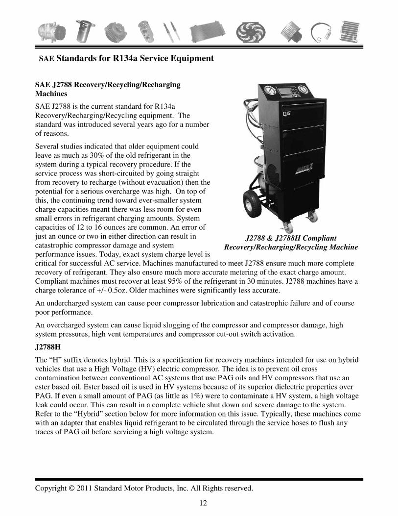
SAE Standards for R134a Service Equipment
SAE J2788 Recovery/Recycling/Recharging
Machines
SAE J2788 is the current standard for R134a Recovery/Recharging/Recycling equipment. The standard was introduced several years ago for a number of reasons.
Several studies indicated that older equipment could leave as much as 30% of the old refrigerant in the system during a typical recovery procedure. If the service process was short-circuited by going straight from recovery to recharge (without evacuation) then the potential for a serious overcharge was high. On top of this, the continuing trend toward ever-smaller system charge capacities meant there was less room for even small errors in refrigerant charging amounts. System capacities of 12 to 16 ounces are common. An error of just an ounce or two in either direction can result in catastrophic compressor damage and system performance issues. Today, exact system charge level is critical for successful AC service. Machines manufactured to meet J2788 ensure much more complete recovery of refrigerant. They also ensure much more accurate metering of the exact charge amount. Compliant machines must recover at least 95% of the refrigerant in 30 minutes. J2788 machines have a charge tolerance of +/- 0.5oz. Older machines were significantly less accurate.
An undercharged system can cause poor compressor lubrication and catastrophic failure and of course poor performance.
An overcharged system can cause liquid slugging of the compressor and compressor damage, high system pressures, high vent temperatures and compressor cut-out switch activation.
J2788H
The “H” suffix denotes hybrid. This is a specification for recovery machines intended for use on hybrid vehicles that use a High Voltage (HV) electric compressor. The idea is to prevent oil cross contamination between conventional AC systems that use PAG oils and HV compressors that use an ester based oil. Ester based oil is used in HV systems because of its superior dielectric properties over PAG. If even a small amount of PAG (as little as 1%) were to contaminate a HV system, a high voltage leak could occur. This can result in a complete vehicle shut down and severe damage to the system. Refer to the “Hybrid” section below for more information on this issue. Typically, these machines come with an adapter that enables liquid refrigerant to be circulated through the service hoses to flush any traces of PAG oil before servicing a high voltage system.
J2788 & J2788H Compliant
Recovery/Recharging/Recycling Machine

Copyright © 2011 Standard Motor Products, Inc. All Rights reserved.
13
J2791 and J2913 Electronic Leak
Detectors
Because of reduced charge capacities, even a small leak can result in a performance issue and possible compressor damage much more quickly than the same leak on a larger capacity system. The need to detect ever-smaller leaks has become much more critical.
In response to the need for more reliable and accurate leak detection, SAE International published J2791 for R134a electronic refrigerant leak detectors several years ago. J2791 leak detectors can find leaks as small as .14 oz/year (4 grams) per joint. The old standard was .5 oz (14 grams). They are also less sensitive to false triggering and are more robust.
Note
SAE has now issued a new standard, J2913 for R1234yf leak detectors. Detectors meeting this standard must be able to differentiate between a 4, 7 and 14 gram leak (approximately 0.141, 0.247 and 0.5oz). Some detectors meet both J2791 and J2913 standards.
State Regulations – R134a
California (and possibly other states) is proposing to introduce their own restrictions on the use of R134a similar to those underway in Europe. Their proposal would likely require the use of a low GWP refrigerant in new vehicles.
Wisconsin has had a law in place since October 1994 prohibiting sales of container sizes holding less than 15 lbs of R134a. However, this restriction applies only when the chemical is intended to be used as a refrigerant. For example, it is legal for a person to purchase gas duster containers with any amount of the chemical because in that instance, the chemical is neither intended to be a refrigerant nor is HFC-134a included in the listing of Class I and Class II substances.
J2791 Electronic Leak
Detector for R134a
Refrigerant
Combination J2913
and J2791 Leak
Detector – Detects
R134a & R1234yf
Copyright © 2011 Standard Motor Products, Inc. All Rights reserved.
14
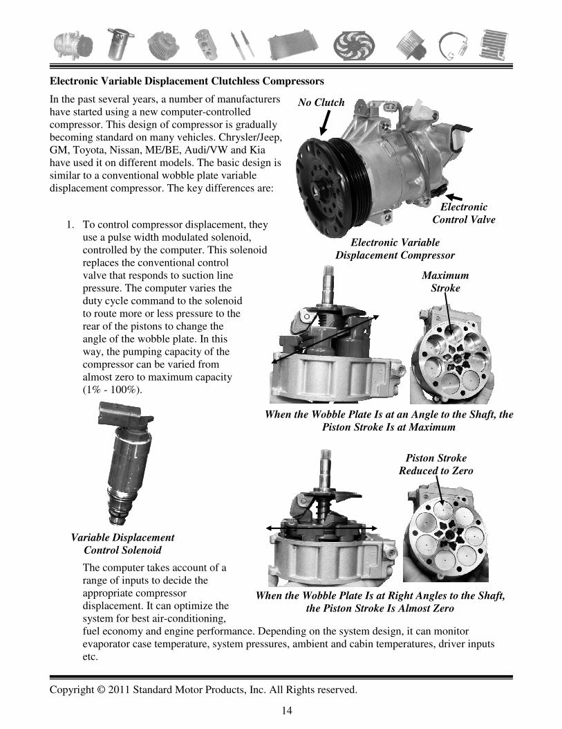
Electronic Variable Displacement Clutchless Compressors
In the past several years, a number of manufacturers have started using a new computer-controlled compressor. This design of compressor is gradually becoming standard on many vehicles. Chrysler/Jeep, GM, Toyota, Nissan, ME/BE, Audi/VW and Kia have used it on different models. The basic design is similar to a conventional wobble plate variable displacement compressor. The key differences are:
1. To control compressor displacement, they use a pulse width modulated solenoid, controlled by the computer. This solenoid replaces the conventional control valve that responds to suction line pressure. The computer varies the duty cycle command to the solenoid to route more or less pressure to the rear of the pistons to change the angle of the wobble plate. In this way, the pumping capacity of the compressor can be varied from almost zero to maximum capacity (1% - 100%).
The computer takes account of a range of inputs to decide the appropriate compressor displacement. It can optimize the system for best air-conditioning, fuel economy and engine performance. Depending on the system design, it can monitor evaporator case temperature, system pressures, ambient and cabin temperatures, driver inputs etc.
When the Wobble Plate Is at an Angle to the Shaft, the
Piston Stroke Is at Maximum
Maximum
Stroke
When the Wobble Plate Is at Right Angles to the Shaft,
the Piston Stroke Is Almost Zero
Piston Stroke
Reduced to Zero
Variable Displacement
Control Solenoid
Electronic Variable
Displacement Compressor
Electronic
Control Valve
No Clutch

Copyright © 2011 Standard Motor Products, Inc. All Rights reserved.
15
2. There is no electric clutch – the compressor shaft turns all the time when the engine is running, even with the AC off. Lubrication is especially critical. Note: The system must be properly charged with refrigerant and oil at all times to maintain adequate lubrication These compressors are designed to keep more of the oil charge circulating within the unit to maintain lubrication even when the AC is off. The compressor pulley contains a damper to absorb engine torque fluctuations and a limiter mechanism that allows the spoke portion of the pulley to break away in the event that the compressor locks up. This allows the compressor pulley and any other accessories driven by the same belt to continue to turn.
Electronic Variable
Displacement - Compressor
Control
The computer varies the duty cycle command to the compressor control solenoid to match the heat load on the system. When the heat load is high, the computer increases the “On” command to the solenoid. The oscilloscope patterns shown here illustrate the command to the solenoid at idle on a 2008 Dodge Caliber during both low and high heat load conditions. The solenoid is permanently grounded and is positive pulsed by the computer. Quick Tip: The computer is in complete command of the compressor pumping displacement. If you find that the compressor does not appear to be building pressure, even after evacuating and recharging the system, do not immediately condemn it. The computer may not be sending the correct signal to the solenoid.
Solenoid + Duty
Cycle = 87%
Solenoid Current = 0.8A
High Heat Load – Greater Duty Cycle Command to Solenoid
(87%). Solenoid Current = 0.8A
Solenoid + Duty
Cycle = 43%
Solenoid Current = 0.4A
Low/Medium Heat Load – Medium Duty Cycle Command to
Solenoid (43%). Solenoid Current = 0.4A

Copyright © 2011 Standard Motor Products, Inc. All Rights reserved.
16
For example, if the solenoid is unplugged, the compressor defaults to minimum displacement – about 1% of capacity. Check for HVAC and engine management system trouble codes that might be inhibiting AC operation. Check also for inaccurate sensor inputs that might cause the computer to send the incorrect command to the solenoid – e.g. inaccurate system pressure sensors, inaccurate evaporator or ambient/cabin temperature sensor readings.
Stretch to Fit Belts
General Motors started using “Stretch to Fit Belts” on the 2008 Hummer H3 and 2009 full sized trucks: Silverado, Avalanche, Tahoe, Suburban, Express Van, Sierra and Yukon.
They are also used on midsized pickups and SUVs such as the Colorado, Trailblazer, Canyon and Envoy and on Saab 9-7 and Cadillac CTS-V.
Ford uses stretch to fit belts for the power steering on 2008 and up Edge, MKX, Fusion, Milan MKZ and MKS with 3.5/3.7L engines.
Chrysler uses stretchy belts on the power steering pump of 2007 and up 2.7L engines.
The belt is very similar in appearance to a conventional serpentine belt. However, the reinforcing cord is made of a polyamide material which is more elastic than the aramid or polyester cord used in traditional belts. The Polyamide cord, when combined with a more elastic backing compound, gives the belt it's “stretch” quality. As a result, the belt is able to maintain proper tension throughout its life without the use of a tensioner.
Note: GM states that once the engine is operated with the stretch belt installed, the belt cannot be removed and reused. It is designed to be removed by cutting it off.
Ford and Chrysler indicate that the belts can be reused provided special tools are used to remove and reinstall the belts.
Removing Stretch to Fit Belt on GM
Vehicles
Using Special Tool to Install Stretch to Fit Belt on GM Vehicles
Several Manufacturers Make a Tool for This Purpose
Belt Installation Tool
Belt Installation Tool
Copyright © 2011 Standard Motor Products, Inc. All Rights reserved.
17
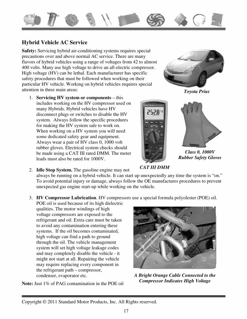
Hybrid Vehicle AC Service
Safety: Servicing hybrid air-conditioning systems requires special precautions over and above normal AC service. There are many flavors of hybrid vehicles using a range of voltages from 42 to almost 400 volts. Many use high voltage to drive an all-electric compressor. High voltage (HV) can be lethal. Each manufacturer has specific safety procedures that must be followed when working on their particular HV vehicle. Working on hybrid vehicles requires special attention in three main areas:
1. Servicing HV system or components – this includes working on the HV compressor used on many Hybrids. Hybrid vehicles have HV disconnect plugs or switches to disable the HV system. Always follow the specific procedures for making the HV system safe to work on. When working on a HV system you will need some dedicated safety gear and equipment. Always wear a pair of HV class 0, 1000 volt rubber gloves. Electrical system checks should be made using a CAT III rated DMM. The meter leads must also be rated for 1000V.
2. Idle Stop System. The gasoline engine may not always be running on a hybrid vehicle. It can start up unexpectedly any time the system is “on.” To avoid potential injury or damage, always follow the OE manufactures procedures to prevent unexpected gas engine start-up while working on the vehicle.
3. HV Compressor Lubrication. HV compressors use a special formula polyolester (POE) oil. POE oil is used because of its high dielectric qualities. The motor windings of high voltage compressors are exposed to the refrigerant and oil. Extra care must be taken to avoid any contamination entering these systems. If the oil becomes contaminated, high voltage can find a path to ground through the oil. The vehicle management system will set high voltage leakage codes and may completely disable the vehicle - it might not start at all. Repairing the vehicle may require replacing every component in the refrigerant path – compressor, condenser, evaporator etc.
Note: Just 1% of PAG contamination in the POE oil
A Bright Orange Cable Connected to the
Compressor Indicates High Voltage
Toyota Prius
CAT III DMM
Class 0, 1000V
Rubber Safety Gloves

Copyright © 2011 Standard Motor Products, Inc. All Rights reserved.
18
in a hybrid system can compromise the dielectric strength of the POE oil. PAG oil residue from the service hoses of your equipment could allow this to happen. You should only use Recovery/Recycling/Recharging equipment meeting SAE specification J2788H - the H suffix stands for “hybrid.” This equipment is designed to avoid hybrid HV AC system contamination. See page 12 for more detail on these machines. Use a separate, dedicated oil injector to install the POE oil into a HV system (unless your equipment manufacturer expressly states that their machine can handle this task).
However, once you know the proper procedures for working with the high voltage system and take care to avoid oil cross contamination, then working on hybrid HV air-conditioning is much the same as working on conventional air-conditioning. Outside of the electric compressor, most of the other components in the system are conventional. Components can be replaced and the system serviced using conventional tools and techniques.
Note: Some Honda Hybrid vehicles use a combination belt driven and high voltage electric motor driven compressor. The front half of the compressor is a belt driven scroll and accounts for about 85% of the compressor pumping capacity. The rear half is a brushless electric motor driven scroll. It accounts for about 15% of the compressors capacity. During idle-stop operation, when the gas engine shuts off, the small electric motor scroll can provide temporary air-conditioning assist. The point is that just because you see a belt, don’t assume that it is a low voltage compressor.
Caution: Even after following the high voltage disable procedure use a Cat III DMM while wearing HV gloves to check that there is no voltage present at the system or component you are about to work on.
About Hybrid Compressors
Hybrid vehicles may use one of three basic compressor types:
1. A conventional 12V, belt driven compressor with a clutch, similar to a normal AC system. 2. A high voltage AC or DC compressor. These compressors are driven by the same high voltage
used for the vehicle propulsion system. They are easily identified by the bright orange cables attached to the compressor. They do not have a belt and may run when the gas engine is off.
15% Pumping Capacity
Belt Driven Scroll
HV Electric
Motor Scroll
85%Pumping Capacity
Suction Discharge
Honda Combination Belt and Electric Motor Driven Scroll Compressor

Copyright © 2011 Standard Motor Products, Inc. All Rights reserved.
19
3. A combination belt driven and high voltage compressor (used on some Hondas) as described above.

Copyright © 2011 Standard Motor Products, Inc. All Rights reserved.
20
SERVICE TIPS AND PATTERN FAILURES
Quick Restricted Condenser Check.
Many later model vehicles use a high side pressure transducer. The transducer is usually located on the compressor discharge line while the high side service port is located on the liquid line. By comparing high side pressure indicated on the scan tool (discharge pressure) versus gauge pressure (liquid line pressure), you can get some indication if the condenser is restricted. Note that some pressure drop across the condenser is normal. Actual normal pressure drop depends on several factors, including heat load on the system, system design, etc. You will need to gain some experience using the technique by checking known good vehicles regularly.
Read Liquid
Line Pressure
on Gauge Set
Condenser Restriction Check – Compare Discharge Pressure on Scan
Tool to Liquid Line Pressure on Gauge – Note: Some Drop Is Normal
Read Discharge
Pressure on Scan Tool Pressure
Transducer
High Side
Service Port

Copyright © 2011 Standard Motor Products, Inc. All Rights reserved.
21
Belt and Tensioner Service Typically, the air-conditioning compressor is the largest single accessory load on the vehicle. Each component in the accessory belt drive system (ABDS) must be in good condition to ensure smooth compressor operation. The belt tensioner performs two distinct functions:
• Maintain correct tension on the drive belt • Dampens torque fluctuations in the ABDS system
caused by the engine firing, the compressor and other accessory loads.
The tensioner can fail in several ways: the spring may lose tension causing belt slippage, wear and squealing. The damper can fail causing excessive belt slap and vibration. The pivot bushing and/or pulley bearing can fail causing uneven belt wear and alignment issues. The circumstances leading up to compressor failure often put the tensioner under excessive strain. AC head pressure may be very high causing the tensioner/damper assembly to bottom out repeatedly and fail. When the compressor is replaced, a belt slippage or vibration problem can be attributed to the replacement compressor when in fact the problem is due to the failed tensioner assembly. A careful check of the tensioner, the belt and other ABDS components should therefore be performed. The alternator and fan clutch are also substantial loads on the system. Their operation should also be checked. Note: Most modern belts are made from an EPDM material which may not show classic signs of belt failure such as cracking. The friction surface may look OK yet be badly worn. ABDS Quick Tip Diagnosing ABDS squealing/chirping noise: with the engine running, use a water spray bottle to spritz the underside of the drive belt. If the noise gets worse, it is probably a belt tension issue; if the noise is reduced, it is probably an alignment issue in the ABDS.
Ford Variable Displacement Scroll Compressor Issue
2005 – 2007 Ford Five Hundred, Freestar and Montego models use a variable displacement scroll compressor. The compressor capacity can be infinitely varied between 30% and 100% of output. Variable displacement is achieved with a spool type control valve, with an integral bellows. The bellows expands and contracts in response to suction line temperature/pressure. This moves the control valve back and forth. As the valve moves, more or less refrigerant is allowed to recirculate inside the compressor to vary output. The control valve bellows can fail resulting in reduced
Ford Scroll Compressor –
Control Valve Can Fail
Causing Reduced Output
The Compressor Is the Largest
Accessory Load – ABDS Must be in
Good Condition to Drive It
Belt Tensioner: Check
Spring Tension, Damper
Function, Pivot Bushing
& Bearing Wear

Copyright © 2011 Standard Motor Products, Inc. All Rights reserved.
22
compressor output. High side pressure will be low and low side pressures will be high with poor performance. The compressor is sensitive to minute amounts of contamination that can cause the valve to stick – important to keep in mind when flushing.
Ford E Vans - Mid 1990’s - 2004
Air-conditioning and Drivability Issues
Depending on the time of year, the customer may complain of some or all of the following symptoms:
• No AC operation
• Poor defrost function
• Surging idle
• Repeat AC clutch failure
If the problem occurs during the winter, the symptom is usually a surging idle or poor defrost function. During the summer, the symptom is usually no AC operation.
Refer to the wiring diagram on this page. Note that the AC clutch voltage must cross four switches before reaching the clutch. Note also that three of the switches would be cycled frequently during normal use: the ignition switch, the AC mode switch and the clutch pressure-cycling switch. With so many active switches in series, the potential for a substantial cumulative voltage drop in the circuit is high.
If the AC cycling pressure switch starts to fail, several symptoms can occur.
• As the voltage drop across the failing switch contacts increases, the available voltage at the clutch decreases. Eventually the clutch starts to slip, burns up, and finally fails. It may also take out the compressor due to warping of the compressor case or failure of the front seal from the excessive
AC
Clutch
Function
Selector
Switch
AC Clutch
Cycling
Pressure
Switch
PCM
Hot In
Run
AC
Pressure
Cutout
Switch
Clutch
Diode
AC Clutch Circuit Has Four Switches in Series –
Increased Likelihood of Large Voltage Drop

Copyright © 2011 Standard Motor Products, Inc. All Rights reserved.
23
heat generated by the slipping clutch. If the clutch or the compressor are replaced without the underlying cause of the original failure being identified a repeat failure is likely to occur.
• When the voltage drop across the cycling switch becomes so great that there is not enough current to engage the clutch, then another unusual symptom can occur. When the AC (or defrost) is first turned on, current starts to build in the clutch circuit. However, the failing cycling clutch switch contacts are not able to carry the rising current and the switch goes open almost instantly. The clutch never actually engages. Note from the wiring schematic, that there is a splice off the AC clutch circuit after the cycling switch that goes to terminal 41 at the PCM. This is the AC “On” input to the PCM. It signals the PCM to raise the idle to compensate for the air-conditioning load. However, in this case the PCM only sees battery voltage on the circuit for an instant before the failing switch contacts break apart because they cannot handle the rising current flow. The PCM raises the idle speed in anticipation of the AC coming on, but lowers it again an instant later when the input signal goes away at pin 41. When the switch contacts cool off, they come back together momentarily and the cycle starts over again. The typical symptom is a regularly surging idle when the AC or defrost are turned on. This can be a tricky diagnoses, especially during the winter when you might not be thinking about air-conditioning!
Quick Tip: This circuit configuration was used by Ford for about ten years and similar versions even longer. There is a strong likelihood of a substantial voltage drop developing in the circuit as the vehicle ages. It can cause any or all of the symptoms described above. It is a good idea to check the voltage drop at the AC clutch on these vehicles when performing any kind of AC service - especially when replacing the clutch or the compressor. The voltage should never be less than 12V with the engine running and ideally should be within one volt of system voltage. This is also a good check to perform as part of a preventative maintenance check of the air-conditioning system.
If the customer’s concern is a surging idle, monitor the “A/C Cycling Switch” input PID on a scan tool. If the PID momentarily changes to “On” intermittently, suspect that the cycling pressure switch may be no good.
2004 - 2006 Ford 6.0L Diesel E 350/450 Vans
AC Compressor Failure.
The AC compressor may fail. The compressor on these vehicles is a low mount scroll design. They are particularly sensitive to charge level – either an undercharge or overcharge. To correct the problem, Ford has revised the refrigerant and oil capacities and also issued a calibration update for the PCM. The refrigerant charge capacities have been reduced to prevent slugging and the oil capacity of the single evaporator system increased to improve lubrication.
On front AC only systems, the refrigerant charge level has been reduced to 32oz from 40oz and the oil charge level has been increased to 11 oz from 9 oz.
On dual AC systems, the refrigerant charge level has been reduced to 54oz from 60oz. The oil charge level remains the same at 13 oz.

Copyright © 2011 Standard Motor Products, Inc. All Rights reserved.
24
Note: When scroll compressors suffer a catastrophic failure, they create a lot of debris. It is usually necessary to replace the condenser in conjunction with the orifice tube and the accumulator. All other components not being replaced should be thoroughly flushed including the evaporator.
2007 and Later GM Vehicles – In-the-Line Filter
Starting in 2007 GM began phasing in an in-the-line liquid line filter on various vehicles – both cars and trucks. At first glance the filter looks very similar to an orifice tube. However, it is just a filter and there will be a separate orifice tube or TXV valve in the system. The filter simply slips into the line much the same wasy as an orifice tube. It is usually installed at at coupling in the liquid line. The filter can be found in various locations – at the condensr outlet, just before the expansion device before the fire wall and on some dual evaporator applications it is located in the liquid line just before the rear TXV valve. The key is to be aware of it. If the compressor fails the filter will almost certainly be clogged. It must be replaced.
Starting 2007 - GM In-the-Line Filter
Located in Liquid Line

Copyright © 2011 Standard Motor Products, Inc. All Rights reserved.
25
Rotary Vane Compressor Issue
Saturn and Other Vehicles that Use a Rotary Vane
Compressor
The customer concern is usually poor AC performance. High side pressure will be lower than normal and low side pressure will be higher. The problem often occurs after the air-conditioning system has not been used for some time. It can also occur immediately after a new or remanufactured compressor is installed. Normal diagnostics will indicate that the compressor cannot build pressure.
Refer to the picture on the right of a rotary vane compressor with one end removed.
When you turn a conventional piston design compressor by hand, even slowly, you can feel the suction and pressure forces at the suction and discharge ports. However, for a rotary vane compressor to start pumping, the vanes must be thrust out against the rotor sidewalls by centrifugal force. The rotor must be turning rapidly before the compressor starts to pump.
When the compressor is unused for a while, the vanes may seize in their slots and not slide out against the rotor sidewalls. The problem can also occur in a perfectly good new or remanufactured compressor if it has been in storage for a while. Before condemning the compressor, try the following procedure to free the vanes:
• Charge the system with half the specified amount of refrigerant.
• Raise the engine speed to 2500 RPM.
• Cycle the compressor on and off every few seconds while monitoring system pressures. If the rotor vanes are stuck, this procedure will usually dislodge them and the compressor will start pumping again.
• When the compressor starts to build pressure, add the remaining refrigerant to bring the system up to full charge. Perform a maximum heat load temperature test to confirm that the system is performing efficiently.
Note: Variable displacement compressors such as GM V5 and V7 units can suffer from a similar problem. The wobble plate can stick at a shallow angle - usually after a period of disuse. The problem can usually be corrected with the technique outlined above for rotary vane compressors.
Both rotary vane and wobble plate design variable displacement compressors are especially sensitive to oil viscosity.
The Rotor Vanes
Can Stick In the Slots
Copyright © 2011 Standard Motor Products, Inc. All Rights reserved.
26
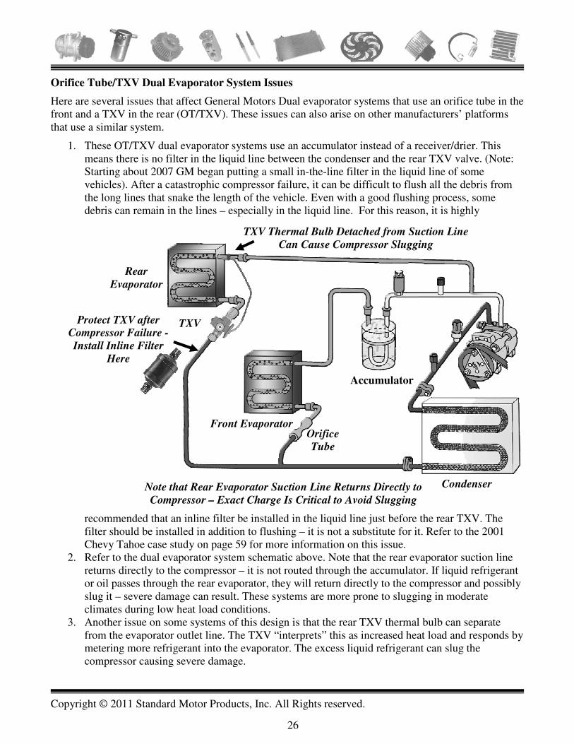
Orifice Tube/TXV Dual Evaporator System Issues
Here are several issues that affect General Motors Dual evaporator systems that use an orifice tube in the front and a TXV in the rear (OT/TXV). These issues can also arise on other manufacturers’ platforms that use a similar system.
1. These OT/TXV dual evaporator systems use an accumulator instead of a receiver/drier. This means there is no filter in the liquid line between the condenser and the rear TXV valve. (Note: Starting about 2007 GM began putting a small in-the-line filter in the liquid line of some vehicles). After a catastrophic compressor failure, it can be difficult to flush all the debris from the long lines that snake the length of the vehicle. Even with a good flushing process, some debris can remain in the lines – especially in the liquid line. For this reason, it is highly
recommended that an inline filter be installed in the liquid line just before the rear TXV. The filter should be installed in addition to flushing – it is not a substitute for it. Refer to the 2001 Chevy Tahoe case study on page 59 for more information on this issue.
2. Refer to the dual evaporator system schematic above. Note that the rear evaporator suction line returns directly to the compressor – it is not routed through the accumulator. If liquid refrigerant or oil passes through the rear evaporator, they will return directly to the compressor and possibly slug it – severe damage can result. These systems are more prone to slugging in moderate climates during low heat load conditions.
3. Another issue on some systems of this design is that the rear TXV thermal bulb can separate from the evaporator outlet line. The TXV “interprets” this as increased heat load and responds by metering more refrigerant into the evaporator. The excess liquid refrigerant can slug the compressor causing severe damage.
Orifice
Tube
Condenser
Front Evaporator
Rear
Evaporator
Accumulator
TXV
Note that Rear Evaporator Suction Line Returns Directly to
Compressor – Exact Charge Is Critical to Avoid Slugging
Protect TXV after
Compressor Failure -
Install Inline Filter
Here
TXV Thermal Bulb Detached from Suction Line
Can Cause Compressor Slugging

Copyright © 2011 Standard Motor Products, Inc. All Rights reserved.
27
Various GM Trucks and Cadillac CTS 2002 – 2004
Compressor Noise/Failure Affected Models: 2003-2004 Cadillac CTS 2002-2004 Cadillac Escalade and Escalade EXT 2003-2004 Cadillac Escalade ESV 2002-2004 Chevrolet Avalanche, Express, Silverado, Suburban, and Tahoe 2002-2004 GMC Denali, Denali XL, Savana, Sierra, Yukon, Yukon XL 2002-2004 Commercial Upfitter Chassis Vehicles The symptoms vary depending on how far the failure has progressed:
• The compressor may have failed outright and is inoperative. • The serpentine belt and tensioner may be slapping or vibrating excessively. • Pressure gauges (especially the high side gauge) may be vibrating/bouncing excessively. • The compressor may be making a rattling noise, especially on acceleration.
The original compressors on these vehicles are prone to liquid slugging. Broken reed valves in the compressor usually cause the belt vibration and pressure pulsations described above. For a lasting repair, the compressor, condenser, orifice tube, accumulator and rear TXV may need to be replaced. Any sections of the refrigerant path not being replaced, including both evaporators on a dual system, should be thoroughly flushed. On a dual evaporator system, the installation of an inline filter before the rear TXV is strongly recommended. There is no receiver/drier or other filter in the system to protect the rear TXV. If a filter is not installed, the rear TXV may become restricted shortly after the repair. 2002 - 2004 Honda CR-V - Compressor Failure These vehicles use a low mounted scroll design compressor that is prone to failure. Scroll type compressors are particularly sensitive to both liquid slugging and lack of lubrication. Honda TSB 09-076 indicates that if evidence of debris is found in the suction line at the inlet to the compressor, then every component in the refrigerant path should be replaced – compressor, condenser, drier, evaporator, all lines and hoses and the TXV. This solution may not always be practical for many consumers. However, for a successful lasting repair, certain parts must be changed and procedures followed carefully. Note: When scroll compressors fail, they produce a lot of debris, which will be distributed throughout the AC system. At a minimum, the compressor and the condenser/receiver drier must be changed. Inspect the TXV inlet for debris and or contaminated oil. If evidence of either is found the TXV valve

Copyright © 2011 Standard Motor Products, Inc. All Rights reserved.
28
should be replaced. All other components not being replaced should be thoroughly flushed including the evaporator. Refer to the section on flushing for special tips and tools on effective flushing. Note About Honda Condensers
These systems are very finely balanced. This system only uses 18oz of refrigerant. For the system to cool properly, every component must operate at maximum efficiency. It is not enough for the replacement condenser to “look similar” to the unit being removed. It must also have the same heat exchange efficiency. Compare the overall size, tube count and the fin density of the replacement condenser with the old unit – they should be a close match. 2006 - 2008 Honda CR-V and Civics – AC Performance Issue Affected Models 2006 – 2008 Civic with automatic transmission and all 2007 - 2008 CR-Vs The customer concern is usually a momentary drop off in AC performance under hard acceleration from below 20 mph. The problem is that the PCM is disengaging the compressor too soon on acceleration. Honda has issued a flash update to address this concern in TSB # 07-062. However, the TSB points out that compressor disengagement is normal under hard acceleration and that the symptom may not be completely eliminated by the calibration update.
Dodge Trucks - Late 1990s – Early 2000s
The Customer Concern
Occasionally, the AC starts blowing warm air. The problem can be very intermittent – it may only occur on longer trips or during stop/go traffic. This can make it particularly difficult to diagnose. There are no diagnostic trouble codes set.
The compressor clutch coil may be going open circuit intermittently. The clutch coils on some of these compressors have a higher than normal failure rate. The coil potting material cracks and exposes the coil winding leading to failure.
One way to confirm the diagnosis is to monitor the voltage across the clutch with a DMM or oscilloscope and wait for the problem to occur. If the compressor stops turning but full system voltage is still available then it is probably a failing clutch coil. Compare the resistance of the clutch coil before and after the problem occurs. Also, check the air gap. An excessive gap can also cause intermittent clutch engagement.
Excess Heat has Cracked the
Potting and Exposed the
Clutch Coil Winding Causing
Premature Failure of the Coil

Copyright © 2011 Standard Motor Products, Inc. All Rights reserved.
29
SERVICE PROCEDURES Essential Steps for Successful Compressor Replacement
1. Replace the Accumulator or Receiver/Drier
• To maintain the compressor warranty, the drier must be replaced during installation of replacement parts.
2. Replace The Orifice Tube/Liquid Line
• The orifice tube is the main filter in a CCOT system. If it is not replaced, the replacement compressor will not be lubricated properly and will fail. Some orifice tube systems have the tube crimped into the liquid line. The liquid line must be replaced or an orifice tube repair kit installed to prevent compressor failure and poor system performance.
3. Inspect/Replace the Thermostatic Expansion Valve (if equipped)
• TXV inlets must be checked for debris or metal particles. Any restrictions will lead to poor performance or compressor failure.
4. Flush the System With Approved Flush
• When the system is repaired, every inch of the refrigerant path should be either new or flushed. Oil acts like fly paper. It will trap and hold metal debris - particularly in the evaporator. Removal of all dirty oil and debris is essential to avoid repeat compressor failure. Newer condenser designs are difficult, if not impossible to thoroughly clean, and in many cases must be replaced.
5. Add the Correct Type and Amount of Oil
• Oil is the lifeblood of an A/C system. Running the compressor without adequate lubrication for even a short while will cause catastrophic damage. Unless instructed otherwise by the compressor instruction sheet, add half the oil charge to the compressor. On orifice tube systems, add the other half of the oil charge to the accumulator. On TXV systems add the other half to the evaporator. Check that you are using the correct:
• Oil type: PAG, Ester or Mineral • Amount • Viscosity
6. Check Compressor Clutch Air Gap Before Installation
• The air gap is preset at the factory; however, it is a good practice to double check it before mounting the unit. Incorrect air gap will cause poor performance or noisy operation. Air gap specs are on the instruction sheet. Check the gap at three points around the clutch.
Replace Receiver
Drier, Accumulator &
Orifice Tube
Thermal
Expansion
Valve (TXV)

Copyright © 2011 Standard Motor Products, Inc. All Rights reserved.
30
7. Proper Evacuation Time
• The A/C system must be free of moisture and air to work properly. Single evaporator systems should be evacuated for at least 45 minutes and dual evaporator systems for at least 90 minutes. Longer evacuations produce colder duct temperatures. A warm engine or sun-load on the vehicle will evacuation.
8. Correct Refrigerant Type and Amount
• Either R-12 or R-l34a should be the only refrigerants used to maintain system integrity and warranty. The correct amount of charge is critical for proper performance. Too little and there will not be enough liquid refrigerant to carry the oil around the system; too much will slug the compressor causing irreparable damage.
9. Before First Start-up, Hand-turn The Compressor Shaft at least 15 Times with the Hose
Assembly Installed
• Oil and liquid refrigerant cannot be compressed. Hand turning the compressor shaft will clear oil and refrigerant from the compression area and reed valves.
10. Burnish The Clutch Assembly
• This process will increase the grip between the clutch hub and the clutch pulley and enhance system performance. With the engine @ 2000 rpm, cycle the compressor clutch off and on twenty times using the A/C control switch on the dash
11. Clutch Electrical Circuit Tests
• Perform a voltage-drop test at the compressor clutch with the clutch engaged. Available voltage should be within 1.5V of system voltage but never less than 12V. It is always a good practice to perform a vehicle charging system test including a battery load test as part of this procedure.
12. Proper Air Flow Through The Condenser And
Radiator
• Inadequate airflow through the condenser and radiator will cause excessive discharge pressures, poor performance, and compressor or clutch failure. Always clean the condenser
Check Fan Clutch Operation –
Bearing Play, Seal Leaks
Turn Compressor at Least 15 Times
by Hand Before Start-up – Use
Compressor Turning Tool
Copyright © 2011 Standard Motor Products, Inc. All Rights reserved.
31
and radiator, check the cooling fan or fan clutch, check for air dams and radiator seals. Check between the radiator and condenser for debris. Check the coolant level in the radiator, as well as the radiator cap for pressure range and sealing.
13. Check for Leaks
• Use an electronic leak detector or fluorescent dye to check for leaks. A leak will cause system failure. A job that was performed perfectly in every other way can still come back with a failed compressor if a leak goes undetected. When the refrigerant level falls too low, there will not be enough liquid refrigerant to carry the oil around in the system and maintain compressor lubrication.
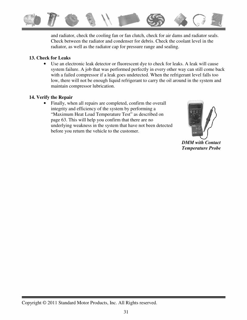
14. Verify the Repair
• Finally, when all repairs are completed, confirm the overall integrity and efficiency of the system by performing a “Maximum Heat Load Temperature Test” as described on page 63. This will help you confirm that there are no underlying weakness in the system that have not been detected before you return the vehicle to the customer.
DMM with Contact
Temperature Probe

Copyright © 2011 Standard Motor Products, Inc. All Rights reserved.
32
Lubrication Oil is the lifeblood of the AC system. Without proper lubrication, the compressor will fail quickly. R134a and PAG oil do not mix well. Maintaining lubrication in an R134a system is more difficult than it was in old R12 systems. R12 and mineral oil mixed and bonded much more easily. Even in a gaseous state, R12 still carried some oil back to the compressor. In an R134a system, the oil is carried around the system by the liquid refrigerant. Refrigerant enters the evaporator as a liquid and evaporates as it passes through the evaporator. As the refrigerant evaporates, the oil tends to drop out. If the refrigerant charge level drops too low, there is not be enough liquid refrigerant remaining to carry the oil up and out of the evaporator and back to the compressor. The oil drops out and pools in the bottom of the evaporator. The compressor starves for oil and fails rapidly. For this reason exact system charge level is critical for proper lubrication. Cycling Clutch Orifice Tube (CCOT) Systems are particularly sensitive to undercharging. Adding Oil
• Add the specified capacity, type and viscosity of oil. Confirm this information from several sources if possible.
• When performing any major service work, all of the oil should be removed from the system. Remove the compressor and accumulator / receiver drier and drain all the oil. Remove the oil from the evaporator and condenser by flushing with the proper solvent, tool and technique (read the section on flushing page 43).
Note: Multi-pass condensers should only be flushed to remove oil. If the compressor has suffered catastrophic failure these condensers cannot be flushed. They should be replaced (refer to the section on flushing).
• Add half of the oil charge to the compressor and half to the accumulator or other components. • Most remanufactured compressors do not contain a full oil charge. The complete amount of
specified oil must be added to the compressor through the suction port or oil plug before installing it on the vehicle.
• Rotate the compressor shaft by hand at least fifteen times after all the hoses are attached but before the engine is started. This moves the oil out of the compressor to avoid liquid slugging on start up.
• The old method of “Oil Balancing” to determine the proper amount of oil is extremely inaccurate. There are way too many variables and unknown factors. The system should be flushed and a complete system charge of oil installed.
About Oils
There are many different types of refrigerant oils in the Market, today. Mineral based to synthetic blends are available with various viscosity ranges. Mineral, parafinic, Ester, and PAG oils have been designed with certain characteristics that each compressor manufacturer has determined, through testing, to provide the best lubrication. The table following lists the type and viscosity of each oil recommended by each compressor manufacturer.

Copyright © 2011 Standard Motor Products, Inc. All Rights reserved.
33
Compressor Manufacturer And Type Oil Type and Grade for R134a Systems and
Those Retrofitted From R12
Special Notes: Virtually all R12 systems used Mineral/500 oil. Ford used a parifinic oil in the FS6 with R12. GM used a special Retrofit oil when retrofitting a V5 compressor from R12 to R134a and when not replacing the V5 compressor. Behr / Bosch Rotary Type (Make sure Comp will handle 134a)
PAG 46
Behr / Bosch Piston Type (Make sure Comp will handle 134a)
PAG 46
Calsonic V5 PAG 150 Calsonic V6 PAG 46 Chrysler RV2 PAG 46 Chrysler C171, A590, 6C17 PAG 46 Diesel Kiki / Zexel DKS, DKV, DCW PAG46 Ford FS6, FX15, FS10, FS20, 10P, 10PA, HS15, HS17, HS18, E6DH, Scroll
PAG 46
General Motors Harrison A6, R4, DA6, HR6, HT, V5, V7, HU,
PAG 150
General Motors CVC, Nippondenso and Nipp. Replacements
PAG 46
Hatachi PAG 46 Keihin (NOTE: Some Keihin compressors are not recommended to be retrofitted to R134a)
PAG 46
Matsushita FX80, FX105 PAG 100 Matsushita NL Series PAG 100 Nihon Be sure the compressor will handle R134a
PAG 46
Nippondenso 6P, 10p, 10PA, 10PO8E, SP127, SP134, 6E171 10S17, 10S20, 6C17, 6CA176, VS16N
PAG 46
Nippondenso TV PAG 100 Panasonic PAG 46 Sanden SD500 Series, SD700 Series PAG 100 Sanden SDV710, SDB Series, TV, TRS PAG 46 Seiko-Seiki PAG 100 York / Tecumseh PAG 46 All Brands of High Voltage Compressors HV Ester
Copyright © 2011 Standard Motor Products, Inc. All Rights reserved.
34
Refrigerant Recovery, Recycling and Recharging
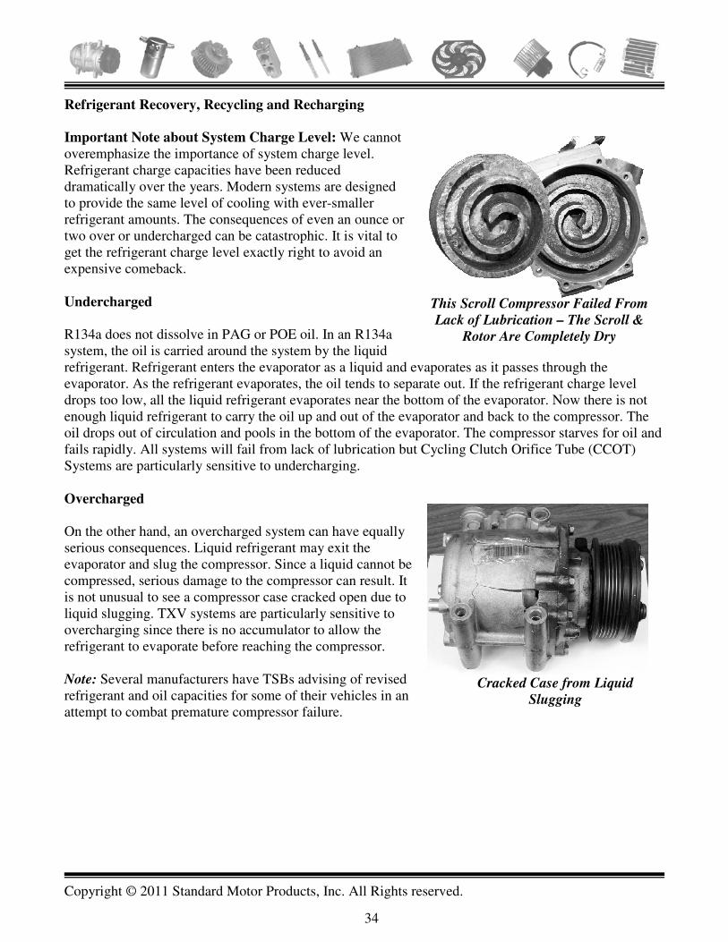
Important Note about System Charge Level: We cannot overemphasize the importance of system charge level. Refrigerant charge capacities have been reduced dramatically over the years. Modern systems are designed to provide the same level of cooling with ever-smaller refrigerant amounts. The consequences of even an ounce or two over or undercharged can be catastrophic. It is vital to get the refrigerant charge level exactly right to avoid an expensive comeback. Undercharged R134a does not dissolve in PAG or POE oil. In an R134a system, the oil is carried around the system by the liquid refrigerant. Refrigerant enters the evaporator as a liquid and evaporates as it passes through the evaporator. As the refrigerant evaporates, the oil tends to separate out. If the refrigerant charge level drops too low, all the liquid refrigerant evaporates near the bottom of the evaporator. Now there is not enough liquid refrigerant to carry the oil up and out of the evaporator and back to the compressor. The oil drops out of circulation and pools in the bottom of the evaporator. The compressor starves for oil and fails rapidly. All systems will fail from lack of lubrication but Cycling Clutch Orifice Tube (CCOT) Systems are particularly sensitive to undercharging. Overcharged On the other hand, an overcharged system can have equally serious consequences. Liquid refrigerant may exit the evaporator and slug the compressor. Since a liquid cannot be compressed, serious damage to the compressor can result. It is not unusual to see a compressor case cracked open due to liquid slugging. TXV systems are particularly sensitive to overcharging since there is no accumulator to allow the refrigerant to evaporate before reaching the compressor. Note: Several manufacturers have TSBs advising of revised refrigerant and oil capacities for some of their vehicles in an attempt to combat premature compressor failure.
This Scroll Compressor Failed From
Lack of Lubrication – The Scroll &
Rotor Are Completely Dry
Cracked Case from Liquid
Slugging

Copyright © 2011 Standard Motor Products, Inc. All Rights reserved.
35
Recovery Refrigerant recovery is important for several reasons:
1. It Is Required by Law
R134a and R12 are considered “greenhouse gasses” that contribute to global warming. It is illegal to vent them to the atmosphere. R12 is also an ozone depleter. These refrigerants (and others) must be recovered and appropriately processed using approved recovery/recycling equipment.
2. System Charge Level If you are performing a normal maintenance AC service to recover, evacuate and recharge the system (without opening it up), then you need to be certain that:
• All the refrigerant has been completely removed from the system before recharging it.
• The amount you charge back is exactly the specified amount the system calls for. Average system capacity has been reduced dramatically over the past 10 to 15 years. Today, system capacities of 12 to 16 ounces (oz.) are common. A few systems are even less than that. If a recovery machine failed to recover 2 oz. from a 12 oz. system and the shop tried to short circuit the service process by going straight from recovery to recharge (without evacuation) a serious overcharge could occur. When the system is charged with the specified 12 oz. it would be about 16% overcharged. Compressor slugging with catastrophic damage could occur. Note: This scenario would only happen in the event that the evacuation part of the service was bypassed – in other words if you went straight from recovery to recharging without evacuating the system. Modern recovery/recycling /recharging equipment will not allow transition from recovery to recharging when in automatic mode. Several years ago, the Society of Automotive Engineers (SAE) recognized that existing standards for refrigerant recovery equipment were not precise enough to meet the recovery and charge accuracy requirements of newer vehicles with reduced charge capacities. Studies had shown that older equipment could leave up to 30% of the refrigerant in the system during a normal recovery operation. SAE developed a new standard, J2788, for recovery/recycling/recharging equipment to meet the more exacting recovery and recharging needs of reduced capacity systems. A recovery/recycling/recharging machine meeting the J2788 standard (J2810 for recovery only equipment) must recover at least 95% of the refrigerant charge in 30 minutes or less at 70-75°F ambient.
3. Quality of Recovered Refrigerant
Recovered refrigerant must be sufficiently pure and free of contamination so that it will not affect system performance or longevity when reused. Air, particulates, old oil and other contaminants must be removed. The key to maintaining high quality recovered refrigerant is proper equipment maintenance and vigilance.

Copyright © 2011 Standard Motor Products, Inc. All Rights reserved.
36
Recovered Refrigerant - Contamination
Sealer Contamination
Before connecting any equipment to a vehicle that you are unfamiliar with, use a sealer identifier to check for the presence of sealer. Undetected sealer can ruin your refrigerant identifier, recovery/recycling/recharging equipment, recovered refrigerant and contaminate the next vehicles you service. Most sealers depend on the presence of either air or moisture to work – neither of which you want in an AC system. Eventually sealers coagulate throughout the system. Repairing a sealer-contaminated system will usually require replacing every component in the refrigerant path. Sealer cannot be flushed.
Air Contamination
Air is a non-condensable gas at the temperatures and pressures found in an automotive AC system. It remains in gaseous form throughout the system and takes up valuable heat exchange real estate in both the condenser and evaporator. This reduces system performance and puts additional strain on the compressor by raising system pressures. Compressor noise is often caused by air in the system. Air also supports corrosion and chemical deterioration in the system over time. This can lead to leaks and other component failures. During both recovery and evacuation, the AC system and the recovery/evacuation equipment are under vacuum. Inevitably, air will find its way into recovered refrigerant unless preventative measures are taken. Keeping air out of recovered refrigerant is like trying to keep sand out of a beach house!
Note: Most recovery/recycling/recharging machines have an automatic air-purge function. However, this feature has limitations. To check for air content these machines compare the actual pressure in the tank of recovered refrigerant with what the pressure would be in a tank of virgin refrigerant at that temperature. If air is present, the pressure in the recovered refrigerant will be higher. The auto air-purge function bleeds off
Sealer Detection Tool
Use an Air Contamination Gauge Set Attached to the Recovery Tank Vapor Port to Confirm that Recovered
Refrigerant is Free of Air. At a Stabilized Temperature, the Two Gauges Should Indicate the Same Pressure. The Top Gauge Reads Actual Tank
Pressure, the Bottom Gauge Indicates what the Pressure Would be in a Tank of Virgin Refrigerant. If
the Pressure on the Top Gauge is Higher that the Bottom Gauge then the Refrigerant Contains Air. Open the Vapor Valve Periodically Until the Two
Gauges Read the Same Pressure. It Can Take Up to 48 Hours to Completely Vent All the Air.

Copyright © 2011 Standard Motor Products, Inc. All Rights reserved.
37
pressure in the recovery tank until the pressure in the tank is close to what it would be in a tank of pure R134a. However, the EPA is concerned that refrigerant should not be vented to the atmosphere. They have set standards for “acceptable air contamination in reclaimed refrigerant.” The EPA considers 2% air contamination acceptable. Compare the pressure/temperature relationship chart on page 93 for virgin R134/R12 with the “acceptable” air contamination pressure/temperature chart for “Reclaimed Refrigerant Contamination” on page 94. Note that at a given temperature, the acceptable pressure in a tank of reclaimed R134a (or R12) is several PSI higher than it would be in a tank of pure refrigerant at the same temperature. Therefore, to avoid any possibility of venting refrigerant to the atmosphere, recovery machines typically only vent down to the higher pressure on the “Reclaimed Refrigerant Contamination” chart. In effect, this means that there could be up to 2% air in your recovered refrigerant. The other concern with auto air-purge is time. It can take up to 48 hours for the trapped air in recovered refrigerant to outgas completely. As the auto air-purge function vents the recovery tank pressure down to the “acceptable” level, additional air will start to outgas from the refrigerant and pressure will start to build up again. It can take up to 48 hours for all the air to outgas completely from a tank of recovered refrigerant as the air-purge function goes through successive venting cycles. In a busy shop environment, as equipment is moved from one vehicle to the next, there simply is not enough time for the auto-air-purge function to vent all the air. One solution to this issue is to use two recovery tanks. Use one tank for recovery only until it is full. Leave the machine on to allow the auto-purge feature time to vent the air. When the tank is full replace it with an empty one. Now use the stabilized tank of recovered refrigerant with a separate charging cylinder or scales for charging.
Rogue Refrigerant
Use a refrigerant identifier to confirm that the vehicle you are about to recover from is not contaminated with a rogue refrigerant. Use of refrigerants other than R12 or R134a will void your compressor warranty. A wide variety of problems can arise with the use of other refrigerants.
• They may be flammable. • Blended refrigerants can be unstable and separate into their component parts. The different
constituents may leak at different rates over time (due to different molecular sizes) causing the refrigerant to perform unpredictably.
• They may attack materials in the system. • The pressure/temperature profile will be different from R134a or R12, making diagnosis
difficult.
Recovery Recycling Only Machine

Copyright © 2011 Standard Motor Products, Inc. All Rights reserved.
38
Recovery Quick Tips Following are some tips to help you ensure that all the refrigerant is completely recovered from the system and that your recovered refrigerant remains free of contamination: • Maintain equipment. Perform the manufactures recommended maintenance service on schedule. Pay
particular attention to the quick disconnect service couplings. They are a common source of leaks that are not always obvious - they may hold pressure but not vacuum. They are complex components with quite a number of internal parts, including several seals and springs. They are high wear items as they are repeatedly connected and disconnected from the system under pressure. Replace your machines filter regularly. J2788 machines track filter life and lock the machine down when filter is used up.
• Use Heat. Heat has a dramatic effect on the rate of refrigerant recovery from a system. Servicing air
–conditioning when the ambient temperature is low, increases the length of time it takes to recover refrigerant from the system. In addition, as recovery begins and refrigerant starts to evaporate, it absorbs heat from its surroundings due to the latent heat of evaporation effect. This slows the recovery process even further. This is why the accumulator or receiver drier feels cold to the touch during recovery. If the drier still feels cold after recovery is apparently complete, then you know that all the refrigerant has not been removed from the system. Carefully warming the drier with a heat gun will accelerate the recovery process.
For rapid recovery, set the AC system on MAX heat and recirculate with the hood lowered. This will warm all the underhood AC components and the evaporator. Note: If the vehicle uses an electronic variable displacement clutchless compressor (see page 14) do not run the engine during recovery or if the system is low on refrigerant or oil. The compressor turns all the time the engine is running and could be damaged from lack of lubrication.
• Periodically use your refrigerant identifier to check for air in your refrigerant recovery tank and also
in vehicles you have just recharged.
• After the vehicle is repaired, use tamper resistant shrink-on or tie-wrap system guards to seal the service ports. If the vehicle returns to you for service and the system guards are missing or have been tampered with, you know the system may have been worked on since you serviced it.
Shrink-on or Strap-on System Guards Help to Deter Tampering

Copyright © 2011 Standard Motor Products, Inc. All Rights reserved.
39
System Evacuation
A thorough evacuation produces colder duct temperatures. System evacuation is necessary to remove all air and moisture from the AC system. Air is a non-condensable gas (NCG). It remains in a gaseous state throughout the AC system and takes up valuable heat exchange real estate in both the condenser and evaporator. This reduces system efficiency. It also raises system head pressure, which increases compressor stress and noise. Air also holds moisture, which creates additional problems. Moisture creates immediate and long-term effects in the AC system. In the short term, it freezes at the expansion device, impeding refrigerant flow and reducing performance. As the moisture freezes, refrigerant flow is reduced and the system starts to blow warm. Now the moisture starts to thaw and refrigerant flow increases. The cycle starts over again. Cycling back and forth from cold to warm is a strong indication that there is moisture contamination in the system. Moisture also holds dissolved oxygen, which can support the creation of acids and corrosive chemical activity over time. Corrosion eventually causes leaks as it eats through the thin heat exchange surfaces of the evaporator and condenser. Corrosion debris can restrict the expansion device and damage the compressor. Following a good evacuation procedure will remove the maximum amount of air and moisture from the system. However, there are no real shortcuts. Removing moisture from the system takes time. Moisture is removed by literally boiling it from the system. The only way to get water to boil at shop temperature is to reduce the pressure on it. The two keys to rapid, effective evacuation are a deep vacuum and heat. Refer to the “Boiling Point of Water at Specific Inches of Vacuum” chart on page 96. Note that vacuum must reach 29.4 inches of mercury (inHg) before water will boil at 60°F. If you are evacuating a system on a 60°F day and the needle on the low side gauge is pointing at 29 inHg exactly, then you are not removing any moisture from the system. 29 inHg “looks” good, but it is not enough on a 60°F day. Referring to the chart again, we can see that on an 80°F day, 29 inHg would be enough to evacuate the system eventually. However, a combination of both deep vacuum and heat are the key to rapid evacuation. The low side gauge on a standard air-conditioning gauge set is not an accurate enough tool for assessing true vacuum. Differentiating between 29 inHg and 29.4 inHg is barely the width of the needle. A micron vacuum gauge is a much more accurate tool. For example, on a micron vacuum gauge, 29.14 inHg reads as 20,000 microns while 29.89 inHg reads as 750 microns – small changes in vacuum become much more obvious.
Vacuum “Looks” Good at 29” –
But on a 60°F Day Not Good
Enough – Must to be 29.4”
Use a Micron Vacuum Gauge to
Measure True Evacuation Vacuum

Copyright © 2011 Standard Motor Products, Inc. All Rights reserved.
40
To use the micron gauge, tee it into one of the service hoses as close to one of the vehicles service ports as possible. An ideal vacuum for automotive air-conditioning is less than 500 microns but below 750 microns is acceptable. The key to achieving a deep vacuum is maintaining equipment. This means changing the vacuum pump oil frequently at the manufacturers recommended intervals. This is usually based on hours used and could mean every couple of weeks during a hot humid AC season. The other weak point in evacuation equipment is usually the service hose quick-disconnect couplings. They undergo a lot of wear and tear as they are continuously connected and disconnected to each system. Inevitably, they develop leaks. Leaks are not always obvious as they may only occur under vacuum and not under pressure. The couplings should be serviced or replaced regularly. Evacuation Time Single evaporator systems should be evacuated for at least 45 minutes and dual evaporator system for at least 90 minutes. Evacuation Quick Tips
• Maintain evacuation equipment. • Regularly validate the ability of your vacuum pump to
pull a deep vacuum with a micron vacuum gauge. • Use heat – warm all the air-conditioning components
on the vehicle by running the engine with the hood lowered. Also, run the heater on max recirculate with the blower on high. This will warm the evaporator. Warming all the AC components dramatically accelerates both refrigerant recovery and system evacuation. Note: If the system uses a clutchless compressor, (where the compressor shaft turns all the time) do not run the engine without refrigerant or oil in the system.
Moisture Contaminated Vacuum Pump
Oil after Just a Few Hours of Service
Change Vacuum Pump Oil at
Recommended Intervals

Copyright © 2011 Standard Motor Products, Inc. All Rights reserved.
41
System Charging
Exact charge level is critical – refer to the note about system charge level and the consequences of under or overcharging on page 33. System undercharging causes lack of compressor lubrication and overcharging causes compressor slugging. In either case, catastrophic consequences can result. With many system capacities now less than 1lb, old charging methods and equipment can easily result in a gross under or overcharge. Just a two-ounce undercharge on a thirteen-ounce system (e.g. some Honda Fits) amounts to a 15% error – enough to cause lubrication issues. Older equipment can be off by as much as 3 to 4 ounces on charge amount. In addition, most older equipment does not compensate for the refrigerant that remains in the hoses after charging. This can be significant – up to about one ounce per foot of hose. Charging Quick Tips
• Use Recovery/Recycling/Recharging equipment that meets SAE J2788 specifications (see page 12). These machines are much more accurate than previous equipment and are specially designed to take account of the reduced charge capacities of newer vehicles. They can be programmed for the specific hose length being used on the machine.
• Consider using a charging cylinder or electronic scale for charging. These are very accurate methods. Another advantage of using separate equipment is that you can improve shop productivity. By using separate Recovery/Recycling/Recharging equipment, you can service three vehicles simultaneously.
• Verify and calibrate electronic charging scales with a known weight every week during peak AC season.
• Service hoses that have been pulled into a vacuum during evacuation can hold four to six ounces of refrigerant, depending upon hose length and manifold design. J2788 compliant equipment automatically compensates for refrigerant trapped in the hoses. However if you are using older equipment or a separate charging scales or cylinder with a manifold gauge set, then you should manually compensate for the refrigerant that remains in the hoses after normal charging. There are two ways to do this.
1. Add about one ounce per foot of service hose to the specified charge amount. If the
system specification was 20 oz. and your service hoses were four feet long, then you would set your charging machine to charge 24 oz. of refrigerant to compensate for the four oz. that would remain in the hoses.
Use a Charging Cylinder For Improved Charge
Accuracy

Copyright © 2011 Standard Motor Products, Inc. All Rights reserved.
42
2. An alternative method is to draw any refrigerant remaining in the hoses into the system after the initial charge is complete. Disconnect the high side service hose from the system. Leave the low side connected. Open the high and low side manifold valves and run the engine with the AC on. This will draw any refrigerant remaining in the entire service hose and gauge assembly into the low side of the system. At low side pressure (30 – 40 PSI) all the refrigerant in the hoses swill be in a gaseous state. There will be virtually no refrigerant remaining in the hoses.
• Let the system stabilize for several minutes before engaging the compressor clutch if liquid
refrigerant has been installed in the high side. This will eliminate the possibility of slugging the compressor and breaking a piston or reed valve.
• Charging by individual cans will usually lead to an undercharged condition due to the refrigerant loss that occurs when each can is change. There will always be residual refrigerant left in each can. It’s only a guess, as to how much refrigerant was in the can to begin with. The other question is, how do you determine the contents of a partial used can? Another issue to contend with is the introduction of air into the system. Air can enter through the service hose as the cans are changed.

Copyright © 2011 Standard Motor Products, Inc. All Rights reserved.
43
Flushing
Note: When a system has suffered a catastrophic compressor failure, it is essential that when the repair is complete, every inch of the refrigerant path is either new or flushed – this includes the evaporator.
Flushing – Why Is It Necessary?
• To remove the failed compressor’s debris from any components that are not being replaced.
• To remove dirty oil from the system – especially from the evaporator.
A Successful Flush Requires:
1. A high quality flush solvent. A good solvent should have the following properties:
• Be effective at removing oil and debris.
• It must evaporate rapidly. Any residue remaining in the system can affect system performance and cause chemical deterioration in the system over time.
• Be chemically stable. It must not react with or attack materials in the system.
• Be safe. Have low flammability and not be a health hazard.
Products such as brake cleaner, de-greasers, carburetor cleaners, denatured alcohol, etc should not be used as flushing agents.
2. An effective flushing tool or machine. A good flush tool should propel the flush solvent
through the component being flushed and maintain the solvent momentum throughout the flush process. When all the flush solvent is dispensed, it should be possible to transition from flush to air-purge without allowing airflow through the component to stop. This prevents the flush solvent from “dropping out” inside the evaporator (or other component). Even a small amount of residual solvent or dirty oil can cause rapid failure of the replacement compressor. The tool shown in figure 2. meets these requirements by using an air pressure regulator, a shut off valve and a universal adapter. The adapter enables a fixed connection to the component to be made.
Schrader Valve – Uses
Static Air Pressure. No
Momentum
Figure 1
Ineffective Flush Tool – Uses Static Air
Pressure. Cannot be Attached to Component
Rubber Tip Cannot
Be Attached to Component
Air Pressure
Regulator Universal
Adapter
Figure 2
Effective Flush Tool
(Shown With Evaporator
Removed from Vehicle
for Clarity)
Shut-off Valve
To Capture
Container

Copyright © 2011 Standard Motor Products, Inc. All Rights reserved.
44
This allows air-purge through the component to be continued for 30 minutes after all the flush solvent is dispensed. Air-purge is necessary to ensure that all solvent and oil residue are completely removed. The upgraded flush tool should be available from your parts store. A good flush simply cannot be achieved with the tool shown in figure 1. on the previous page. The static air charge in the can runs out before all the solvent is dispelled. The rubber tipped air blower must be manually held to the component during the flush process – not very practical. The use of a tool like this will result in a contaminated soup of dirty oil and solvent being trapped in the evaporator. The very best flush results are obtained with a professional closed loop flush machine similar to the one shown here in figure 3. These machines allow the use of a greater volume of solvent, are usually flow reversible and have a pulsing action to dislodge trapped debris.
3. A Proper Flushing Technique. A good flushing process requires using a quality solvent and flushing tool in accordance with the manufactures instructions. For example, if you are using a tool similar to the one shown in figure 2, you will need to ensure that a constant supply of dry shop air or nitrogen is supplied to the flush can. Meter about a third of the flush solvent into the evaporator and allow it to soak for 10-15 minutes. Complete the flush at 40 PSI. When all the solvent is expelled from the can, raise the air pressure up to 80 PSI and continue to purge air through the component for an additional 30 minutes to dry out any residue of solvent or oil.
Quick Tips
• Flat tube, multi-pass condensers cannot be flushed – they should be replaced. The internal tubes are extremely small. The image on the right shows a cross-section of early and late design condenser flat tubes (a penny is sandwiched in-between for size reference). The bottom tube is typical of R134a condensers until the mid 2000s. The top cross-section is the very latest design. In addition, the condenser header tanks at each end are dammed in several places forcing the refrigerant to follow a circuitous path through the condenser – flush solvent would have to follow a similar path.
Figure 3
Professional Closed
Loop Flush Machine
The Internal Passages of Flat Tube Multi-pass,
Condensers Are Extremely Small. They Are
Impossible to Flush After a Catastrophic Compressor
Failure. Top Sample is the latest design.

Copyright © 2011 Standard Motor Products, Inc. All Rights reserved.
45
• Hoses and lines with inline filters or mufflers cannot be flushed – they should be replaced. Accumulators and receiver/driers also cannot be flushed. They have convoluted internal passageways and contain the system desiccant – the desiccant will disintegrate on contact with flush solvent.
• It is usually more effective to flush components individually. Trying to flush the entire system at once, or large sections of it, can result in debris being distributed to other areas of the system.
Important Note: Most compressors fail from lack of lubrication. All air-conditioning systems leak refrigerant gradually over time. Eventually there is not enough liquid refrigerant in the system to carry the lubrication oil up and out of the evaporator and back to the compressor. The oil drops out of circulation and pools in the bottom of the evaporator. The compressor eventually fails.
In the weeks and months leading up to the final failure, very fine metal particles slough off the compressor cylinder walls and pistons. These fine particles are carried throughout the system. Some will even pass through the tiny passages in the orifice tube and TXV valve. They are finally trapped in the oil, which has been pooling in the bottom of the evaporator. There they form a contaminated soup of dirty oil and abrasive particles. Think valve-grinding compound! It is critical that this dirty oil is completely flushed from the system before the compressor is replaced. If it is not, premature failure of the replacement compressor is inevitable.
This pooled oil in the evaporator can amount to several ounces and cause additional problems. If the compressor has failed several times already, and the old oil was not removed after each failure, the result can be a gross overcharge of oil as new oil is added with each compressor replacement. In addition to the abrasive damage, the compressor can also be slugged by this excess of oil. Furthermore, the excess of oil coats the heat exchange surfaces of the evaporator and condenser reducing their efficiency.
Accumulators and Receiver
Driers Have Convoluted
Internal Passages. They Also
Contain Desiccant Which
Disintegrates on Contact with
Flush Solvent
Receiver Drier Cutaway
Lines with Inline Filters and
Mufflers Cannot be Flushed
Note Pinhole that Refrigerant
Must Pass Through
Accumulator Cutaway

Copyright © 2011 Standard Motor Products, Inc. All Rights reserved.
46
Leak Checking Hard to find refrigerant leaks are one of the more exasperating aspects of air-conditioning service and repair. A vehicle is brought to you with a complaint of poor performance. You recover, evacuate and recharge the system and it performs perfectly. You know the system was low on refrigerant when it came in yet you cannot find a leak. Or, you repair a system and it comes back after a week, a month or even a year and you find that it’s low on refrigerant. Yet despite your best efforts, you cannot find the leak. With the continuing trend toward ever-smaller system refrigerant capacities, the same leak results in a system performance issue much more quickly than before. Being able to find small leaks has never been more important. Before you begin, look the system over carefully for obvious signs of a leak. On an R134a system, oil does not always show up at the site of a leak because it does not mix well with the refrigerant. However depending on the location and the size of the leak, there may still be some oily residue at the leak site. In this section, we will discuss the various methods of refrigerant leak detection including some new ones. We will also provide some tips that should make leak detection easier and more reliable, regardless of which method you use.
Electronic Leak Detection Electronic leak detection is probably the most common method of leak detection. It is certainly the easiest and fastest to perform. However, it can be unreliable and ineffective if you do not follow a good procedure. Here are some tips for a better electronic leak detection experience:
• There must be some refrigerant in the system – at least 50 PSI. Electronic leak checking in colder weather will be less successful.
• Perform the leak check with the engine off. Stop all airflow across the vehicle. This is extremely important. Ideally, perform the leak check indoors with all shop fans and ventilation shut off. This will greatly increase your success rate with electronic leak detection.
• Conduct the leak-check methodically by working your way across each section of the system. Move the probe tip at about one to two inches per second about ¼-inch from the surface of the line or component being checked. Verify an apparent leak at least once by blowing shop air into the area of the suspected leak, and repeating the check of the area. In cases of very large leaks, blowing out the area with shop air can help locate the exact position of the leak.
• Oil will mask leaks. Allow the vehicle to sit for several hours before performing the leak check. This allows the oil to drain down in the system and expose leaks. However, to check for leaks in the very bottom of the evaporator it may be helpful to check a few minutes after system shut down before all the oil has drained down and obscured the leak.
• While waiting to perform the leak-check, park the vehicle outside in direct sunlight. This raises low side pressure and improves your success rate in finding evaporator leaks. If you need to bring the vehicle inside to complete the leak-check, do NOT run the AC system or the blower

Copyright © 2011 Standard Motor Products, Inc. All Rights reserved.
47
motor. You do not want to stir up the oil or vent the evaporator case before you perform the leak-check.
• To raise static pressure in the system during colder weather, run the engine with the AC off but with the system set on max heat recirculate. This will warm the evaporator. Turn the engine off before performing the leak check. If you suspect an evaporator leak, wait 10 or 15 minutes to allow some refrigerant vapors to build up in the evaporator case.
• Refrigerant is heavier than air. When leak checking the evaporator, try to get the detector tip into the bottom of the evaporator case. Removing the blower resistor block or other easily accessible component from the side of the evaporator case may improve access. Also, check at the evaporator drain. Alternatively, position the detector tip in the dash vent closest to the evaporator and turn the blower on for just a second or two. This may waft refrigerant vapors by the tip of the probe and confirm the leak.
• Use a detector that meets the latest SAE specification. SAE J2791 for R134a electronic leak detectors was issued a few years ago (see page 13). These detectors are more accurate and robust than earlier models and less sensitive to false triggering. Note: SAE J2913 has just been issued for electronic leak detectors designed to work with the new refrigerant R-1234yf. Some new detectors meet both specifications and will detect both R134a and R-1234yf. See pages 11 and 13.
• There may be two or more leaks! After you find and mark the first one, complete your normal routine for checking the entire system.
• Maintain the detector by cleaning and replacing the tip filter per the manufacturer’s instructions. • Compressor front seal leaks can be difficult
to confirm. Try removing the belt and placing a shower cap over the compressor clutch and nose. Wait several minutes and slip the detector tip into the shower cap toward the bottom of the compressor. If it triggers, suspect a compressor front seal leak.
Remove the Belt and Place a Shower Cap
Over the Compressor Nose. Insert the
Detector Tip into the Cap Near the Bottom of
the Compressor to Check for Leaks

Copyright © 2011 Standard Motor Products, Inc. All Rights reserved.
48
Hydrogen Trace Gas Leak Detection A new leak detection method called “Hydrogen Trace Gas Leak Detection”, has recently become available. The technique is not new, but is just now being used for automotive AC system leak checking. The technique uses an electronic leak detector that detects the presence of hydrogen instead of refrigerant. Hydrogen is the smallest and lightest discrete particle with an atomic number of one. It is the first element on the periodic table. The H2 molecule is many times smaller than the complex R134a molecule. This makes it very effective at ferreting out even the smallest leaks. A gas cylinder with a mix of 5% Hydrogen and 95% Nitrogen is used to charge the AC system to about 30 PSI. Although hydrogen gas is extremley flamable, it is safe at this 5% concentration in the nitrogen. The gas mix is available from many welding supply companies. Another advantage of this technique is that if the system is empty, you can charge the system with the Hydrogen/Nitrogen mix and vent the gas directly to that atmosphere when the leak is identified. This saves considerable time since the traditional technique is to charge the system with some refrigerant and use a conventional and less accurate leak detector to check for leaks. The test charge of refrigerant must then be recoverd from the system. Dye Leak Testing Leak checking with a fluorescent dye and ultra violet (UV) light is a reliable and effective leak detection method. However it does have some drawbacks. You must be able to see the point of the leak either directly or at least indirectly by using a mirror or borescope. Confirming evaporator leaks can be especially challenging using dye. Depending on the size of the leak, the system must be run for varying lengths of time before the dye will show up. It can take several days for very small leaks to become apparent. Dye is carried in the oil. If the leak is at a high point in the system where little oil reaches, the leak may not show up at all. In addition, once an area is
Dye Leak Detection Kit
Trace Gas Leak Detection Using a 5% Hydrogen/95%
Nitrogen Gas Mix

Copyright © 2011 Standard Motor Products, Inc. All Rights reserved.
49
stained, the dye must be removed with a special neutralizing fluid before you can recheck and confirm that the leak source has been fixed. Note: You should only use a quarter ounce of dye per system. Dye contains phosphorous which can cause chemical deterioration in the system over time. Most dyes use oil as the carrier. Adding too much has the same effect as adding too much oil – reduced thermal efficiency, slugging etc. Here are some tips that should make dye leak detection a little easier:
• Use the pair of yellow goggles that came with the leak detection kit. They enhance the fluorescent effect.
• The wavelength at which the dye fluoresces and the wavelength of the UV light must be an exact match for each other. You can check this by adding a small drop of dye to some test oil and then confirming that the mixture fluoresces – you need to dilute the dye because a pure sample will usually fluoresce unless it is a complete mismatch for the UV light.
• Perform the leak check in a darkened area if possible. Reducing the ambient light level will allow the dye to stand out more easily.
• Evaporator leak checking: Identifying evaporator leaks with dye is usually done indirectly since it is not often possible to gain direct access to the evaporator. The slower the leak the longer you will need to run the system before the leak shows up. Very slow leaks can take several days and even longer. After the dye has been thoroughly distributed in the system by running it for at least twenty minutes, start by shining the UV light at the evaporator drain hole or tube and look for traces of dye. If the leak does not show up right away, allow the vehicle to sit for several hours. Then catch the very first evaporator condensation drain water in a white Styrofoam cup. Shine the UV light in the cup and look for any traces of fluorescence – even a small spec will be strong evidence that the evaporator is leaking. An alternative method is to attach a long piece of clear plastic hose to the evaporator drain. Operate the system and allow the evaporator condensation to run down the plastic hose. Shine the UV light up and down the hose and watch for tiny specs of florescence. You can also try catching the evaporator condensation in a pure white cloth and shining the UV light on it. Try to swab the inside if the evaporator drain tube or even up into the evaporator case with an extra long cotton bud. Shine the UV light on the bud tip and look for traces of dye.
Catch the First Evaporator Condensation in
a White Cup and Shine a UV Light on it.
Check for Traces of Dye in the Water

Copyright © 2011 Standard Motor Products, Inc. All Rights reserved.
50
A Case Study
The Vehicle:
1998 Jeep Wrangler
4.0L
144,000 Miles
The Customer Concern
This is the customer’s weekend “fun” vehicle. In the fall of the previous year, the compressor failed on a long road trip. From his description of the event, it most likely seized. There was smoke and a loud squealing noise coming from the front of the compressor. The compressor clutch was badly burned up.
The repair receipt from the other shop indicates that they replaced the accumulator, orifice tube and serpentine belt and installed a new compressor. It also indicates that the system was flushed, evacuated and recharged with the correct amount of refrigerant and oil.
It is now spring of the following year and the customer is stating that the same thing appears to have happened again. The AC stopped working and the belt started squealing and smoking. There is less than five hundred miles on the truck since the original repair.
An underhood inspection easily reveals the immediate cause of the problem. There is a huge chunk missing from the side of the compressor case. Both the compressor and accumulator look new but there is evidence that the clutch is burned up. \
Evaluation
Apart from the obviously broken compressor, there is no immediate indication of what caused either the original or the replacement compressor to fail. The engine is not overheating and the fan clutch is operating normally. There are many possibilities. The same undetected root cause may have caused both failures. Or, perhaps the shop that installed the replacement compressor did not follow a good repair procedure which caused the second compressor to fail. At this point, the only option is to replace the compressor again, but this shop wants to be certain that they get it right this time!
By following a thorough, step by step repair process and performing additional diagnostics when the system is operational again, the underlying cause of the failure should be revealed.
New Compressor - Burned Up Clutch, Cracked Case

Copyright © 2011 Standard Motor Products, Inc. All Rights reserved.
51
The technician knows that at least two compressors have failed catastrophically on this truck. Metallic debris from these failures will be trapped in the condenser, which he notes has not been changed. He also considers how the original compressor might have failed:
One of the most common causes of compressor failure is lack of regular maintenance. All air-conditioning systems leak refrigerant gradually over time. This truck uses spring lock hose couplings which are especially prone to leak. Eventually there is not enough liquid refrigerant in the system to carry the oil up and out of the evaporator and back to the compressor, to keep it lubricated. The oil drops out of circulation and pools in the bottom of the evaporator. In the weeks and months leading up to the final failure, very fine metal particles slough off the compressor cylinder walls and pistons. These fine particles are carried throughout the system. Some will even pass through the tiny passage in the orifice tube. They are finally trapped in the oil, which has been pooling in the bottom of the evaporator and form a contaminated soup of dirty oil and abrasive particles. Think valve-grinding compound!
If this contaminated oil is not removed, it will be pushed out of the evaporator and straight to the compressor when the system is repaired and the full charge of refrigerant added. The replacement compressor inevitably fails prematurely. In addition, if the specified amount of oil has been added to the system, the result will be too much oil in the system since the new oil will be added to the dirty oil that has not been flushed from the evaporator.
Taking all these factors into account, if this job is to turn out right, the technician knows that at a minimum he will need to:
• Replace the compressor.
• Replace the condenser.
• Replace the orifice tube.
• Replace the accumulator – although it is almost new it will contain several ounces of contaminated oil.
• He will also need to thoroughly flush any component that is not being replaced.
• Replace all system seals including the spring lock coupling O rings.
The Repair
He begins by flushing the evaporator. He uses a flush can with an air regulator and a universal adapter attached to the evaporator outlet. This enables a much more effective flush than just using the can with a static air charge and a rubber tipped blower. The flush pressure is set at 40 PSI. When the can is empty, he raises the air pressure to 80 PSI and continues to air purge the evaporator for 30 minutes to dry out any remaining solvent or oil residue. He saves the evaporator flush waste and filters it through a clean white cloth. The flush
Universal Flush Adapter
Flushing the Evaporator

Copyright © 2011 Standard Motor Products, Inc. All Rights reserved.
52
waste has a very oily consistency. It is black and heavily contaminated with flecks of tiny metallic particles in suspension.
Note: The technician used a highly evaporative non-oil based flush solvent. The oily consistency of the flush waste indicates that there was a substantial amount of dirty oil trapped in the evaporator.
If this had been allowed to circulate in the system, the third compressor would also have failed prematurely.
A cotton bud wiped inside one of the lines shows a lot of contamination.
One of the suction/discharge hose assembly crimp joints shows faint evidence of leaking and it rotates easily back and forth when twisted by hand. The technician also notices that the male end of the hose assembly spring lock hose coupling is a very loose fit in the evaporator outlet and that the hose exterior is badly deteriorated in
several places. He replaces the hose assembly.
Next, he removes the old condenser and drains it. There is barely any oil in it – most of the oil was trapped in the evaporator. This is strong evidence that the system was probably undercharged. There was not enough liquid refrigerant to carry the oil around the system. What little oil is recovered from the condenser is jet black. This is a flat tube
More Evidence of Contamination Abrasive Particles in the Evaporator Flush Waste
New Suction/Discharge &
Liquid Line Hose Assembly
Hose Joint Is Leaking and Rotates When Twisted
Very Little, Very Black Oil Is Drained
From the Condenser

Copyright © 2011 Standard Motor Products, Inc. All Rights reserved.
53
multi-pass condenser with tiny internal passageways. After a catastrophic failure, debris from the failed compressor will be trapped in the passages. It cannot be flushed.
The compressor is replaced with a remanufactured unit. The condenser, orifice tube, accumulator and hose assembly are also replaced. 8oz of PAG 100 oil are added – 4oz in the compressor and 4oz in the accumulator. He also adds a ¼ of fluorescent dye.
With the compressor mounted and the hoses connected, he turns it through 15 revolutions by hand to move the oil out into the discharge line. This prevents slugging on start up.
The system is evacuated and charged with 20oz of R134a. The truck is run for several minutes to stabilize the system.
The technician checks the voltage drop across the compressor clutch – it is 13 volts, which is acceptable.
Finally, he carefully leak checks the system. All the evidence suggests that the original failures were both due to low on refrigerant charge. He believes he has found the leak by replacing the leaking hose assembly; however, it would not be unusual for a system to have more than one leak. Refer to the section on leak checking for more tips on finding hard to find leaks.
The Flat Tube Multi-pass Condenser is Replaced – It Cannot
be Flushed after a Catastrophic Compressor Failure
Checking Clutch Voltage
Leak Checking the System

Copyright © 2011 Standard Motor Products, Inc. All Rights reserved.
54
Temperature Testing the System
The system is blowing cold duct air. However, before returning the truck to the customer, the technician wants to confirm that the overall AC system is operating at maximum efficiency – that there is no underlying weakness in the system that might result in a comeback or another premature compressor failure. A powerful tool to perform this evaluation and identify hidden weaknesses is a “Maximum Heat Load Temperature Test.” The complete Maximum Heat Load Temperature Test procedure and how to interpret the results is described starting on page 63.
The test results indicate that this system is in balance and operating efficiently. In particular, on this orifice tube type system, the negligible temperature difference across the evaporator confirms that the system is properly charged with enough liquid refrigerant exiting the evaporator to carry lubrication back to the compressor.
Conclusion
Considering the amount of contaminated oil recovered from this evaporator and only the small amount recovered from the old condenser, the compressor failure most likely occurred because of a low charge on both occasions. The low charge was most likely caused by the leaking hose joint and lack of regular maintenance. In addition, judging from the condition and the amount of oil recovered from the evaporator we suspect that the system was not properly flushed after the original failure.
Quick Tip
• After a catastrophic compressor failure, contaminated oil will be trapped in the evaporator. It is very important that this contaminated oil be completely flushed from the evaporator using an effective technique. If it is not, premature catastrophic failure of the replacement compressor is almost inevitable. Refer to the section on flushing for more flushing tips.
• Exact system charge is critical:
o Insufficient charge results in oil being trapped in the evaporator and lack of lubrication.
o Overcharging can result in compressor slugging with irreparable compressor damage.
1998 Jeep Wrangler Temperature Test Results
RESULT Specification
Condenser Inlet 146°F Min 20°F
Max 50°F Condenser Outlet 116°F
Difference 30°F Pass
Evaporator Inlet System
Evaporator Outlet
Difference -1°F Pass
Ambient Air Temp 95 30° or More
Duct Air Temp 57
Difference 38 Pass

Copyright © 2011 Standard Motor Products, Inc. All Rights reserved.
55
A Case Study
The Vehicle:
2001 Ford F150
5.4L VIN L
215,000 Miles
The Customer Concern
She says that on hot days, in stop/go traffic, the AC is not as cold as it used to be. She says it appears to work fine on the highway.
Evaluation
The ambient temperature when the technician checks the truck is 95°F. A test ride confirms the customer’s complaint – the AC works OK at cruise but at idle, the duct temperature creeps up to almost 60°F even with the AC set on MAX, Recirculate. He connects his service equipment to the vehicle service ports and finds that both high and low side pressures are very high at idle. The high side pressure is about 410 PSI and the low side is about 60 PSI. However, when he raises the engine speed to 2500 RPM, both high and low side pressures drop into the normal range and the duct temperature also drops.
Both Low and High Side Pressures Are Very High at Idle
The Engine Is Not Overheating

Copyright © 2011 Standard Motor Products, Inc. All Rights reserved.
56
Direction
If system pressures drop when engine RPM is raised and the duct temperature also improves this is often an indication of an air flow problem across the condenser.
Some basic checks however, do not reveal an obvious problem. While there is some debris on the front of the condenser, it really does not appear to be sufficient to cause this problem. In addition, the engine does not appear to be overheating. The temperature gauge is in the normal range, the cooling fan appears to be operating at full speed, there are no obvious fan clutch issues and there are no missing fan shrouds or seals. The technician makes one last check.
Diagnosis
He removes the header panel that covers the gap between the condenser and the radiator.
The photo below shows what he found - almost the entire front of the radiator is covered with a blanket of fine debris. The technician removes the debris using shop air and a garden hose. With the radiator clean, system pressures fall into the normal range and duct temperature also drops.
At this time it looks like this one is fixed – pressures are normal and duct temperature (doors closed, MAX AC, Recirculate) is now 50°F. However, before returning the vehicle to the customer the technician decides to perform a “Maximum Heat Load Temperature” test to confirm that the entire AC system is performing efficiently and that there is no other problem that may still be undetected.
After Cleaning System Pressures
Fall Into the Normal Range A Blanket of Fine Debris
Covers the Front of the
Radiator

Copyright © 2011 Standard Motor Products, Inc. All Rights reserved.
57
Maximum Heat Load Temperature Test – Results
• Condenser Temperature Drop = 42° F.
Result: PASS – the drop should be between 20 and 50° F. However, the technician notes that the drop is slightly higher than he normally sees on this type of vehicle.
• Ambient to center duct difference = 31° F.
Result: PASS - the drop must be greater than 30° F.
• Evaporator inlet to outlet temperature difference = plus 9.5° F.
Result: FAIL - the drop should be between plus or minus 5°F.
Note: Refer to page 63 for detailed instructions and explanation on performing a “Maximum Heat Load Temperature” test.
Although the system is now performing acceptably, the large temperature increase from the evaporator inlet to the outlet suggests that the system may be undercharged. The technician also checks the compressor case temperature and notes that it is 166° F. Although there is no absolute specification for compressor case temperature, he knows from experience that it is higher than he usually sees on this type of truck under similar conditions. Elevated compressor case temperature can also often indicate a compressor lubrication issue due to a low charge condition. The technician decides to recover, evacuate and recharge the system with the correct amount of refrigerant.
He recovers only 28 oz. of refrigerant – the correct capacity is 33 oz. After evacuation he charges the system with the correct amount and repeats the maximum heat load temperature test. Here are the results:
Maximum Heat Load Temperature Test – After Evacuate and Recharge
• Condenser Temperature Drop = 28° F.
Result: PASS.
• Ambient to center duct difference = 35° F.
Result: PASS.
• Evaporator inlet to outlet temperature difference = minus 2.5° F.
Result: PASS.
Conclusion
This vehicle had two separate air-conditioning system related issues. Excessive debris on the radiator was causing an airflow problem through the condenser, yet was not severe enough to cause the vehicle to overheat. The system was also undercharged by about 15%. Cleaning the radiator restored air-conditioning performance to an acceptable level. However if the technician had not performed additional testing to uncover the undercharged condition, it might have gone undetected. In fact a slight
Duct Temperature After
Cleaning the Condenser

Copyright © 2011 Standard Motor Products, Inc. All Rights reserved.
58
undercharge may result in slightly colder duct temperature! The problem is that an undercharged system does not have enough liquid refrigerant in the evaporator to carry the oil back to the compressor. If the undercharge is not corrected, premature compressor failure from lack of lubrication can result.
By the time a vehicle arrives in your shop with an air conditioning complaint, there may in fact be more than one failure contributing to the problem. If you find a problem and make a repair that restores the system to acceptable performance, don’t assume that the system is completely fixed. It is a good idea to also perform a “Maximum Heat Load Temperature Test” to confirm that the entire system is operating efficiently before returning the vehicle to the customer.
Quick Tip
Develop a habit of checking compressor case temperature during a maximum heat load temperature test. If the case temperature is higher that you normally expect to see on a particular vehicle then suspect a compressor lubrication issue, even if the system is performing adequately. Although there is no general specification that covers all vehicles, you will acquire a feel for what is typical on common compressor types and vehicle platforms that you work on. If the underlying problem that is causing the elevated temperature is not corrected, then premature compressor failure may result.
Measuring Compressor Case
Temperature

Copyright © 2011 Standard Motor Products, Inc. All Rights reserved.
59
A Case Study
The Vehicle:
2001 Chevy Tahoe – With Rear AC
5.3L
140,000 Miles
The Customer Concern
The rear AC started getting warm about a month ago. Two days ago, there was a loud “explosion” under the hood and the AC stopped working completely.
Evaluation
The technician quickly determines that the compressor has seized and that the high-pressure cutout switch has popped out of the compressor. Obviously the pressure got pretty high before the compressor finally failed.
The technician has heard stories about problems with GM dual evaporator systems on some full size trucks. He decides to replace the compressor, the orifice tube, the rear TXV and the accumulator.
When the orifice tube and TXV are removed, there is lots of debris and contamination obvious on both.
The Repair
The technician flushed the system thoroughly using a flush can with an air regulator and a universal adapter attached to the individual components being flushed. The compressor, orifice tube, rear TXV and the accumulator are replaced.
The High Pressure Cut-out Switch Is
Popped Out of the Compressor
The Orifice Tube & TXV Are Badly
Contaminated
Debris from
Rear TXV
Flush Can with Air
Regulator and Universal
Adapter

Copyright © 2011 Standard Motor Products, Inc. All Rights reserved.
60
He also replaced the serpentine belt tensioner and the belt. The truck has 140K miles on it and these components are often damaged when the compressor seizes and the tensioner repeatedly bottoms out in its travel due to the excessive loading from high head pressures and seizing compressor.
The system is evacuated and charged with the correct amount of oil and refrigerant (48oz of R134a and 11oz of PAG 46 oil).
The system is performing well and there is no evidence of any leaks. The truck is returned to the customer.
Aftermath
After several days, the customer returns. The rear AC has started blowing warm again. The front AC is still working fine. System pressures are normal but the technician notes that the rear evaporator outlet line is about 65°F. On a TXV system, if low side pressure is low to normal yet the evaporator outlet temperature is high, it often indicates that the TXV is restricted or not metering enough refrigerant into the evaporator. In other words, there is excessive superheating in the evaporator.
The technician recovers all the refrigerant from the system. He recovers approximately the full system charge which suggests that the system does not have a leak. He removes the rear TXV which was just replaced new, and finds that it is completely clogged.
The Solution
The technician calls a techline. They advise him that this is a common problem on this type of system and that he should install an inline filter in the refrigerant liquid line before the rear TXV. He cuts the liquid line just before the rear TXV and installs a filter.
Dual Evaporator Quick Tips
Dual evaporator GM vehicles that use an orifice tube in the front and a TXV in the rear suffer from several inherent weaknesses:
• These systems do not use a receiver drier, which would normally filter debris from the refrigerant before it reaches the TXV. This makes the rear TXV particularly prone to clogging. Even small amounts of debris from normal compressor wear over time can eventually clog the TXV on this design system.
Debris
The TXV Is Clogged for the
Second Time
Inline Filter Installed Before Rear TXV

Copyright © 2011 Standard Motor Products, Inc. All Rights reserved.
61
• After a catastrophic compressor failure on a dual evaporator system with an orifice tube in the front and a TXV in the rear, it is recommended to install an inline filter in the liquid line before the TXV. Unless a professional closed loop flush machine is used, some stray particles can remain in the long lines of dual evaporator systems. This debris will eventually find its way back to the rear TXV and restrict it if a filter is not installed.
• Another problem with this design is that the suction line from the rear evaporator returns directly to the compressor. It is not routed through the accumulator. If any liquid refrigerant (from say a slight overcharge) or oil passes through the rear evaporator, it will go directly to the compressor causing slugging and possible catastrophic damage. On the other hand, if the system is undercharged, oil can start pooling in both evaporators resulting in no lubrication to the compressor. For these reasons, it is critical that the refrigerant and oil charge levels be exact on these systems.
• During prolonged low heat load conditions on the rear evaporator (e.g. when the rear blower is off or set on low), the refrigerant flow through the evaporator is greatly reduced. This can result in insufficient refrigerant flow through the evaporator to carry oil back to the compressor and can lead to premature compressor failure from lack of lubrication.
• Another issue is that the metal band that straps the TXV sensing bulb to the evaporator outlet can corrode through and leave the sensing bulb flapping in the breeze. The TXV interprets this as increased heat load and increases refrigerant flow through the evaporator to compensate. This can also result in liquid refrigerant slugging the compressor.
TEMPERATURE TESTING THE SYSTEM
Testing the Front Evaporator
After the inline filter has been installed, the system recharged, and leak checked again the technician performs a maximum heat load test to confirm that there is no underlying weakness in the system that might result in a comeback.
The Maximum Heat Load Temperature Test procedure starts on page 63 and describes in detail how to temperature test dual evaporator systems and interpret the results starting on page 68.
On this dual evaporator system with an orifice tube in the front, a slight temperature drop of about 2°F between the evaporator inlet and outlet is ideal but +/-5°F is acceptable. It is -3.8°F, which is within the acceptable range.
Temperature
Probes
Front Evaporator Temperature Test
Difference Between
Center Duct
and Ambient Air
Temperature
Should be Greater than
30°F
Here It Is 43°F Duct & Ambient
Temperature
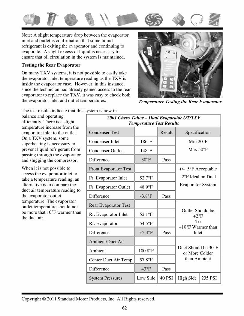
Copyright © 2011 Standard Motor Products, Inc. All Rights reserved.
62
Note: A slight temperature drop between the evaporator inlet and outlet is confirmation that some liquid refrigerant is exiting the evaporator and continuing to evaporate. A slight excess of liquid is necessary to ensure that oil circulation in the system is maintained.
Testing the Rear Evaporator
On many TXV systems, it is not possible to easily take the evaporator inlet temperature reading as the TXV is inside the evaporator case. However, in this instance, since the technician had already gained access to the rear evaporator to replace the TXV, it was easy to check both the evaporator inlet and outlet temperatures.
The test results indicate that this system is now in balance and operating efficiently. There is a slight temperature increase from the evaporator inlet to the outlet. On a TXV system, some superheating is necessary to prevent liquid refrigerant from passing through the evaporator and slugging the compressor.
When it is not possible to access the evaporator inlet to take a temperature reading, an alternative is to compare the duct air temperature reading to the evaporator outlet temperature. The evaporator outlet temperature should not be more that 10°F warmer than the duct air.
2001 Chevy Tahoe – Dual Evaporator OT/TXV
Temperature Test Results
Condenser Test Result Specification
Condenser Inlet 186°F Min 20°F
Max 50°F Condenser Outlet 148°F
Difference 38°F Pass
Front Evaporator Test +/- 5°F Acceptable
-2°F Ideal on Dual
Evaporator System
Fr. Evaporator Inlet 52.7°F
Fr. Evaporator Outlet 48.9°F
Difference -3.8°F Pass
Rear Evaporator Test Outlet Should be
+2°F To
+10°F Warmer than Inlet
Rr. Evaporator Inlet 52.1°F
Rr. Evaporator 54.5°F
Difference +2.4°F Pass
Ambient/Duct Air Duct Should be 30°F
or More Colder than Ambient
Ambient 100.8°F
Center Duct Air Temp 57.8°F
Difference 43°F Pass
System Pressures Low Side 40 PSI High Side 235 PSI
Temperature
Probes
Temperature Testing the Rear Evaporator
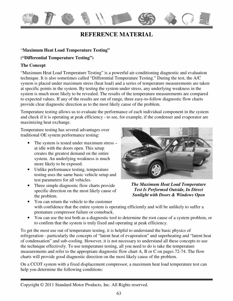
Copyright © 2011 Standard Motor Products, Inc. All Rights reserved.
63
REFERENCE MATERIAL
“Maximum Heat Load Temperature Testing”
(“Differential Temperature Testing”)
The Concept
“Maximum Heat Load Temperature Testing” is a powerful air-conditioning diagnostic and evaluation technique. It is also sometimes called “Differential Temperature Testing.” During the test, the A/C system is placed under maximum stress (heat load) and a series of temperature measurements are taken at specific points in the system. By testing the system under stress, any underlying weakness in the system is much more likely to be revealed. The results of the temperature measurements are compared to expected values. If any of the results are out of range, three easy-to-follow diagnostic flow charts provide clear diagnostic direction as to the most likely cause of the problem.
Temperature testing allows us to evaluate the performance of each individual component in the system and check if it is operating at peak efficiency - to see, for example, if the condenser and evaporator are maximizing heat exchange.
Temperature testing has several advantages over traditional OE system performance testing:
• The system is tested under maximum stress – at idle with the doors open. This setup creates the greatest demand on the entire system. An underlying weakness is much more likely to be exposed.
• Unlike performance testing, temperature testing uses the same basic vehicle setup and test parameters for all vehicles.
• Three simple diagnostic flow charts provide specific direction on the most likely cause of the problem.
• You can return the vehicle to the customer with confidence that the entire system is operating efficiently and will be unlikely to suffer a premature compressor failure or comeback.
• You can use the test both as a diagnostic tool to determine the root cause of a system problem, or to confirm that the system is truly fixed and operating at peak efficiency.
To get the most use out of temperature testing, it is helpful to understand the basic physics of refrigeration - particularly the concepts of “latent heat of evaporation” and superheating and “latent heat of condensation” and sub-cooling. However, it is not necessary to understand all these concepts to use the technique effectively. To use temperature testing, all you need to do is take the temperature measurements and refer to the appropriate diagnostic flow chart A, B or C on pages 72-74. The flow charts will provide good diagnostic direction on the most likely cause of the problem.
On a CCOT system with a fixed displacement compressor, a maximum heat load temperature test can help you determine the following conditions:
The Maximum Heat Load Temperature
Test Is Performed Outside, In Direct
Sunlight with Doors & Windows Open

Copyright © 2011 Standard Motor Products, Inc. All Rights reserved.
64
1. That the A/C system is operating at maximum efficiency and if it is not then what is the most likely cause of the underlying problem.
2. That the system is charged with the right amount of refrigerant.
On a TXV system or a system that uses a variable displacement compressor, the heat load test can provide the following information:
1. That the A/C system is operating at maximum efficiency and if it is not what is the most likely cause of the lack of performance.
2. It can provide some indication of a possible system undercharge or overcharge but not with the same accuracy as on a CCOT system. TXV and variable displacement compressor systems have a feedback component. These systems will try to compensate for an under or overcharge by adjusting the refrigerant flow rate in the system and mask the under or overcharge condition. However, if the system is known to be correctly charged, the temperature test results will expose an underlying weakness in the system and the diagnostic flow charts will point to the most likely underlying cause of the problem.
We have developed a set of temperature testing parameters that are the same for just about any automotive A/C system that you would work on. There are only a few minor variations to take account of basic system design differences (i.e. whether it is a Cycling Clutch Orifice Tube (CCOT), Thermal Expansion Valve (TXV) or a single or a dual evaporator system”.
Following is the temperature testing procedure for a single evaporator CCOT system. Later we will explain the methods for testing TXV and dual evaporator systems.
Maximum Heat Load Temperature Test – CCOT Single Evaporator System
This test is designed to place the AC system under a maximum heat load condition. By monitoring the system temperatures and pressures under the parameters listed below, you will be able to identify marginal or failed system components, and the efficiency of the heat exchange process.
• Bring the engine up to full working temperature with the A/C on. • The test requires a heat load on the system. Place the vehicle outside in direct sunlight. Ideally
the ambient temperature should be 79°F or higher. (Later, we will describe methods of generating heat load during low temperature conditions).
• Set the AC controls to max cold and recirculating air. • Open all doors and windows. • Set blower speed to high position. • Allow System to stabilize (operate at idle for at least five minutes).
Now take the temperature readings in each of the three tests below. When you have recorded all your temperature readings find the temperature difference between the two readings taken in each of the tests. You will end up with a single temperature number for each test. We call them the three “D”s or “differences.”
1. Condenser Sub-cooling Test. Measure and record the temperatures of the condenser inlet and outlet lines as close to the condenser as possible.
2. Ambient to Duct Air Test. Measure and record the air temperatures at the center AC duct and the ambient air about one foot in front of the condenser.
3. Evaporator Superheat Test. Measure and record the temperature of the evaporator inlet and outlet lines on CCOT / FFOT systems.

Copyright © 2011 Standard Motor Products, Inc. All Rights reserved.
65
Note: Refer to the temperature testing worksheets in the reference material section at the end of the book. Make copies of these worksheets and use them to record the temperature readings for the system you are working on.
Following Are Testing Specifications for an efficiently operating CCOT A/C system:
1. Condenser Sub-cooling Test. The difference between the condenser inlet and outlet line should be between 20°F and 50°F.
2. Ambient to Duct Air Test. Duct air temperature should be at least 30°F lower than ambient air temperature measured about a foot in front of the condenser.
3. Evaporator Superheat Test. Ideally there should be no temperature difference between the evaporator inlet and outlet. 0°F difference is ideal, however, a temperature increase or decrease of up to 5°F across the evaporator is acceptable. On a CCOT system, an evaporator superheat reading within this specification is confirmation that the system is correctly charged.
Now take the numbers recorded in each of the three tests and refer to the appropriate temperature diagnostic chart “A” “B” or “C” on pages 72-74 in the reference material section at the end of the book. Use these diagnostic flow charts to confirm that the system is operating efficiently or to help you determine the likely cause of any problems in the system.
Note: The duct temperature reading that you get during the maximum heat load temperature test is likely to be quite a bit higher than you would get during a system performance test or during normal A/C operation. Remember you are performing the test with the doors open, outside on a warm day! The important number is the difference between ambient temperature and duct temperature. For example, if the ambient temperature is 95°F and the center duct temperature is 60°F, then the ambient to duct air difference is 35°F. This is acceptable. The difference is 5°F greater that the minimum specification of 30°F. Because the system can create at least a 30°F difference between ambient and duct temperature, we know that it has more than enough capacity to reduce the cabin temperature to an acceptable level when the doors are closed.
Important Notes about Taking the Temperature Readings
• Temperature Testing
Tools: For your diagnostic results to be reliable, it is extremely important that the temperature readings are accurate. You will need a good contact type pyrometer or dedicated temperature-testing tool, similar to the ones shown here.
Taking the Temperature Readings:
• When taking the evaporator and condenser inlet and outlet line readings, be sure to make firm, direct metal contact with the line being measured. If necessary, scrape away paint or any accumulated corrosion or dirt from the line. Paint can throw the temperature reading off by as
CPS Temp Seeker –
Dedicated Temperature and
Humidity Testing Tool
DMM with Fluke
Temperature Probe Adapter

Copyright © 2011 Standard Motor Products, Inc. All Rights reserved.
66
much as 20 - 30°F. If you are using an alligator type clip-on probe, rotate it back and forth on the line to be sure it is making firm contact. If you use a Fluke style adapter like the one shown here, hold the probe as perpendicular to the line as possible and keep firm pressure on it.
• Use a probe with a narrow tip. Limited contact area can be a problem if the temperature probe tip is too big. Some vehicles use a very short evaporator outlet pipe between the evaporator case and the accumulator nut. In some cases, only 3/16 of an inch is available for the probe to make contact. Taking readings on flange nuts will skew the actual temperature by more than 20ºF.
• Take the readings as close in as possible to the condenser and the evaporator. • Gaining access to the outlet side of the orifice tube can be difficult on some applications. Some
GM light truck applications place the outlet tip of the orifice tube just inside the evaporator case. You can gain access to the pipe by cutting a small section of the case away with a hot knife. When you are finished, seal the area with permagum or insulation tape.
About Infrared Thermometers: We are often asked if infrared thermometers can be used to perform heat load temperature testing. They CANNOT. The infrared beam spreads much too wide to take the pinpoint readings necessary. The laser is just a pointer – it does not represent the infrared beam. For example, in the images shown here, an infrared thermometer and a contact type temperature probe are being used to measure the temperature of a heated refrigerant charging cylinder at the exact same temperature. Half of the cylinder is bare aluminum while the other half is painted black. You can clearly see that the contact probe readings are within a few degrees of each other regardless of whether they are taken on the bare metal or painted surfaces. (Note: that the paint does make a slight difference). However, when the same readings are taken with an infrared thermometer there is a discrepancy of 30°F between two readings! Even though the contact probe confirms that in fact, the two surfaces are about the same temperature. This is why infrared thermometers cannot be used for heat load temperature testing.
Temperature of Bare Metal and Painted Surface of
Heated Charging Cylinder Measured with Contact
Probe– Only Few Degrees of Temperature Difference
Heated
Refrigerant
Charging
Cylinder
There “Appears” to be a 30 ° F Difference between
the Bare Metal and Painted Surfaces – In Fact They
are Both at the Same Temperature

Copyright © 2011 Standard Motor Products, Inc. All Rights reserved.
67
Nevertheless, an infrared thermometer can still be a useful tool. It can be used to check relative temperature differences – for example scanning back and forth across the front of the condenser checking for restrictions.
Temperature Testing TXV Systems
The vehicle set up for temperature testing a TXV system is identical to a CCOT system.
The “Condenser Sub-cooling” and “Ambient to Duct Air” tests are also the same.
The only difference is in performing the “Evaporator Superheat” test.
Note: TXV systems use a receiver in the liquid line instead of an accumulator in the suction line. On a CCOT system, the accumulator acts as a liquid/vapor separator to prevent any liquid refrigerant from returning to the compressor and slugging it. A TXV system does not have this protection. It is critical that no liquid refrigerant exits the evaporator on a TXV system. The liquid would go straight to the compressor and likely cause catastrophic damage. Therefore, a small amount of evaporator superheating is essential on a TXV system to ensure all the refrigerant is evaporated before it reaches the compressor.
The temperature sensing element of a TXV is constantly measuring evaporator outlet temperature and adjusting the metering of refrigerant into the evaporator to control evaporator superheat.
Evaporator Superheat Test on a TXV System
There are two methods of checking evaporator superheat on a TXV system.
• Direct Measurement. Just as you would on an orifice tube system, simply check the evaporator inlet and outlet temperature. On a typical TXV system, evaporator outlet temperature will be between +2°F and +10°F warmer than the inlet during a heat load temperature test. A few may be slightly higher than this. The actual value depends on the specific superheat rating of the TXV itself. Each TXV is matched to the evaporator and system it is installed in. The specific superheat rating can usually be obtained from the manufacturer’s website or catalog. Be sure to check the TXV inlet temperature on the evaporator side of the TXV. This is where a problem can arise. The TXV is usually located inside the evaporator case and it may not be possible to take a direct inlet temperature reading on the evaporator side of the valve. In this case, you will need to perform an indirect measurement of evaporator superheat.
• Indirect Measurement. If you cannot take a direct measurement of evaporator inlet temperature then it is still possible to infer evaporator superheat indirectly. Compare center duct air temperature with evaporator outlet (suction line) temperature. As a general rule, evaporator outlet temperature should not be more than 10°F warmer than duct air temperature. Think of it this way: if the evaporator outlet temperature was 65°F and duct air temperature was 50°F during a heat load test, you would know that there is at least 15°F of superheating taking place in the evaporator. Some part of the evaporator (close to the inlet) is cold enough to cool the duct air to 50°F, yet by the time the refrigerant leaves the evaporator the temperature has increased by at least 15°F. A disadvantage of this test is that there may be a greater amount of superheating taking place than the 15°F indicated by the test. We are assuming that evaporator inlet temperature is close to the duct air temperature of 50°F. Of course, an air door problem in the
Infrared Thermometer
Copyright © 2011 Standard Motor Products, Inc. All Rights reserved.
68
dash, or a leaking evaporator case seal could allow warmer air to leak into the airflow before the duct; the evaporator inlet could in fact be quite a bit colder than the duct air. This would mean that the evaporator superheating is actually more that the 15°F we have estimated. If duct air and evaporator outlet temperature were within 10°F of each other, we could be misled into thinking that evaporator superheating was within the normal range. However, if this were the case, the “Ambient to Duct Air” test reading would almost certainly be less than 30°F, which would at least let us know that there is still a problem in the system.
Temperature Testing Dual Evaporator Systems
Temperature testing dual evaporator systems is very similar to testing single evaporator systems with just a few minor additional steps.
A few points to note about testing dual evaporator systems:
• Most dual evaporator systems use the same compressor and condenser as the single evaporator model of the same vehicle. This means that the system has to work harder to handle the added heat load of the second evaporator. Both high and low side pressures will be slightly higher on the dual evaporator version of the same system.
• Dual evaporator systems may use all TXVs, all orifices tubes or a combination of both as follows:
o Front Orifice Tube/Rear TXV (OT/TXV) o Front TXV/Rear TXV (TXV/TXV) o Front and Rear Orifice Tube (OT/OT) (not very many)
You need to know what your system has as it will affect you testing procedure slightly.
Maximum Heat Load Temperature Test – OT/TXV Dual Evaporator System
Vehicle Setup
The vehicle set up is virtually identical to a single evaporator setup except as noted.
• Bring the engine up to full working temperature with the A/C on. • Place the vehicle outside in direct sunlight. • Set both front and rear the AC controls to max cold and recirculating air. • Open all doors and windows
o Note: Also open the rear door or hatch. • Set front blower speed to high position
o Note: set the rear blower to low speed only. This is because the total heat load on the system with both blowers on high can exceed the design capacity of the system and cause temperature and pressure readings to be erratic.
• Allow System to stabilize (operate at idle for at least five minutes).
Now take the temperature readings in each of the three tests below. The condenser sub-cooling test is the same as for a single evaporator system. When you have recorded all your temperature readings, find the temperature difference between the two readings taken in each of the tests. You will end up with a single temperature number for each test. We call them the three “D”s or “differences.”
Testing Procedure:
Copyright © 2011 Standard Motor Products, Inc. All Rights reserved.
69
1. Condenser Sub-cooling Test: Measure and record the temperatures of the condenser inlet and outlet lines as close to the condenser as possible.
2. Ambient to Duct Air Test – Front and Rear: Measure and record the air temperatures at the center front and rear AC ducts and the ambient air temperature about one foot in front of the condenser.
3. Evaporator Superheat Test: o Front Evaporator - OT: Measure and record the front evaporator inlet and outlet
temperature. o Rear Evaporator – TXV:
� Direct Measurement: Measure and record the rear evaporator inlet and outlet temperature as described previously for a single evaporator system under the heading “Direct Measurement” on page 63.
� Indirect Measurement: If it is not possible to access the rear evaporator inlet line to take the temperature reading, use the indirect method described for a single evaporator system under the heading “Indirect Measurement” on page 67.
Temperature Testing Specifications for an efficiently operating OT/TXV dual evaporator System:
1. Condenser Sub-cooling Test. The difference between the condenser inlet and outlet line should be between 20°F and 50°F – t he same as for single evaporator systems.
2. Ambient to Duct Air Test. Both front and rear duct air temperature should be at least 30°F lower than ambient air temperature measured about a foot in front of the condenser - same as for single evaporator systems.
3. Evaporator Superheat Test: o Front Evaporator - OT: -2°F ideal, ± 5°F acceptable. The acceptable range (± 5°F) is
the same as for a single evaporator system but the ideal is -2°F instead of 0°F. A slightly negative temperature drop across the front evaporator on an OT/TXV dual evaporator system is preferred as it indicates a slight reserve of liquid refrigerant to handle the heat load of a dual system under extreme conditions.
o Rear Evaporator – TXV: � Direct Measurement: Same as for a single TXV system - evaporator outlet
temperature will be between +2°F and+ 10°F warmer than the inlet during a heat load temperature test. It depends on the superheat setting of the specific TXV valve. Refer to the specifications under the same heading for a single evaporator TXV system on page 67 for additional information.
� Indirect Measurement: Same as for a single evaporator TXV system. Evaporator outlet temperature should not be more than 10°F warmer than the rear duct air temperature. Refer to the specifications under the same heading for a single evaporator TXV system on 63 for additional information.
Now take the temperature readings recorded in each of the tests above and refer to the appropriate temperature diagnostic chart “A,” “B” or “C” on pages 72-74 in the reference material section at the end of the book. Use these diagnostic flow charts to confirm that the system is operating efficiently or to help you determine the likely cause of any problems in the system.
Temperature Testing a Dual Evaporator TXV/TXV Systems
The vehicle set up is the same as for a dual OT/TXV system

Copyright © 2011 Standard Motor Products, Inc. All Rights reserved.
70
Condenser sub-cooling and ambient to duct specifications are also the same.
Both the front and rear evaporator superheating specifications are also the same as for a single evaporator TXV system. Refer to page 67 for specifications and testing details.
Temperature Testing a Dual Evaporator OT/OT Systems
Vehicle set up is the same as for other dual evaporator systems.
Condenser sub-cooling and ambient to duct specifications are also the same.
Evaporator superheat specifications are: -2°F ideal, ± 5°F acceptable, on both evaporators. The same as the front evaporator on an OT/TXV system.
Note: Typically, the front and rear duct temperatures should be within 4°F of each other on a dual evaporator system.
Compressor Case Temperature:
Get in the habit of checking the compressor case temperature on common compressor types of vehicles you are familiar with. It can be a valuable diagnostic aid. There is no absolute specification for compressor case temperature. It will vary widely by compressor type and vehicle and the ambient temperature and humidity on the day. However, with experience gained from regular checking, you will develop a feel for what is normal on the common systems that you work on.
If a system is under undue stress due to a cooling system problem, a restriction in the system or lubrication is not reaching the compressor, case temperature will be elevated.
Before checking case temperature, operate the system for at least 15 minutes under a heat load. Check the temperature in the middle of the case away from the suction and discharge connections.
Checking Compressor Case
Temperature

Copyright © 2011 Standard Motor Products, Inc. All Rights reserved.
71
Methods of Generating Heat Load During Cooler Weather Conditions
For a Maximum Heat Load Test to be effective, the A/C system must be subjected to a substantial heat load. The vast majority of A/C related customer complaints occur during warm weather when generating a heat load is usually not a problem. However when ambient temperature is low (less that 78°F) you can use one of the following methods to artificially generate a heat load on the evaporator. Heater Method
• Close all the doors and windows • Turn the heater on to full heat and run the engine at idle. • Monitor the cabin air temperature until it reaches at least 90ºF • Set the AC controls to MAX AC, recirculating air (this will allow the warmed air to pass over
the evaporator) • Keep the doors and windows closed during the test • Set blower speed on high • Continue to run the engine at idle • First: Measure and record the temperature of the evaporator inlet and outlet lines (CCOT / FFOT
Systems) • Second: Measure and record the temperature of the condenser inlet and outlet lines • Third: Measure and record the center duct outlet and interior air temperatures
Note: Artificially heating the interior air in this way will provide a heat load across the evaporator. The temperature data that you record will provide enough information to determine if excessive superheating is occurring at the evaporator or if proper sub-cooling is taking place at the condenser. Since the ambient air temperature is cool, the airflow across the condenser should be determined mechanically, with an air flow meter or the old rag test. Fresh Air Method
• Run the engine at idle until normal operating temperatures are reached • Set the AC controls on maximum cold and normal or outside air flow • Open all the doors and windows • Set blower speed on high • First: Measure and record the condenser inlet and outlet line temperatures • Second: Measure and record the evaporator inlet and outlet line temperatures • Third: Measure and record the center duct outlet air and the air entering the fresh air cowl (place
the probe inside the air grill). Note: This method allows hot air to enter the fresh air cowl. The air becomes heated as it flows through the engine compartment. It is drawn across the evaporator core. This artificially heated air may climb above 110ºF. This method will allow you to determine if excessive superheating or minimum sub-cooling is occurring. Due to the cool ambient air temperatures, the test may not reveal low condenser air flow. Test for proper air flow across the condenser mechanically.

Copyright © 2011 Standard Motor Products, Inc. All Rights reserved.
72
Repair & Retest
Check for Low
Refrigerant Charge
Test Refrigerant for
Contamination (Non-
Condensable
Gases - Air)
Test Condenser for
Internal Restrictions
R134a Systems
Condensers
Must Be Replaced
Ford Systems
Condensers
With Black Death
Must Be Replaced
No Problems
No Debris
Within Acceptable
Range Less Than 20°F
Clean and Retest
Check Condenser for Air Flow
Bent Fins
Debris on Condenser or
Between Radiator
and Condenser
Inspect For External Air Flow
Measure Condenser Inlet Line Temperature in from of Condenser. Measure Condenser
Outlet and Inlet Line Temperatures as Close as Possible to the Condenser. Note: Some
Systems Place the Orifice Tube Close to the Condenser, Measure In Front of the Orifice
Tube. The Temperature Drop Difference Should Fall Between 20°F and 50°F. If Out of
Range, Follow the Diagnostic Flow Chart. If Within Range, Go to Diagnostic Chart B.
More Than 50°F
Check: Fan Clutch Operation
Electric Cooling Fan Operation
Electric Condenser Fan Operation (If Equipped)
Fan Shroud for Damage
Seals between Radiator and Condenser
Missing/Damaged Air Dams
Test Cooling System
Test for:
Internal Contamination (Black Death)
Refrigerant Overcharge
Incorrect Condenser Installed
Condenser Installed Upside Down
Refer to Diagnostic
Temperature Chart B
Temperature Diagnostic Flow Chart A – Condenser Sub Cooling Test

Copyright © 2011 Standard Motor Products, Inc. All Rights reserved.
73
System Performing to
Specifications
Check for Temperature
Balance Between Duct Air
Drop And Condenser Drop
(Should be Within 10°F )
Less Than 30°F
Check for Outside Heat Entering Cabin
Blend Air Door Not Closing
Heater Valve Not Closing
Fresh Air Door Not Closing
Check Evaporator Condition
Evaporator Fins Dirty or Restricted
Evaporator Interior Coated with Scale
Air Bypassing Evaporator (missing seals)
Check Refrigerant and Oil Charge
Was System Evacuated?
Was System Cleaned?
Was Compressor Oil Level Checked?
CCOT and FFOT Systems
Refer to Temperature Chart C
Measure Ambient Air Temperature Approximately One Foot in Front of Condenser.
Measure Center AC Duct Outlet Air Temperature by Placing the Probe in the Duct. The
Temperature Difference Between Ambient And Duct Air Should Be a Minimum Of 30°F.
If Out of Parameters, Follow The Diagnostic Flow Chart.
More Than 30°F
Temperature Diagnostic Flow Chart B – System Performance Check
Repair as Necessary and Retest

Copyright © 2011 Standard Motor Products, Inc. All Rights reserved.
74
Check System For:
Undercharge Condition
Excessive Oil in the System
Inspect Orifice Tube For:
Restrictions - Dirty Screen
Correct Application (too small)
Outlet Tube
Colder Than 5ºF
Check System for Overcharge Condition
Inspect Orifice Tube For:
Leaking O-Ring Seals
Correct Application (too large)
Measure the Evaporator Inlet Line Temperature on the Evaporator Side of the Orifice
Tube, as Close to the Evaporator Case as Possible. Measure the Evaporator Outlet Line
Temperature Before the Accumulator, as Close to the Evaporator Case as Possible. The
Ideal Temperature Reading Between the Inlet and Outlet is 0°F. The Acceptable
Temperature Range for the OUTLET Tube is from 5°F Colder to 5°F Warmer than the
Inlet Tube. Refrigerant Flowing Within these Temperatures Will be Able to Carry
Sufficient Oil Back to the Compressor. Excessive Outlet Temperature (Super-Heating)
Indicates that All the Refrigerant has Evaporated. There is Insufficient Liquid
Refrigerant Available to Carry the Oil Up, Out of the Evaporator and Back to the
Compressor.
Outlet Tube Warmer
Than 5ºF
Temperature Diagnostic Flow Chart C - Evaporator Superheat Test
Note: Diagnostic Chart C applies to orifice tube systems. Most TXV systems do not
provide easy access for superheat testing.

Copyright © 2011 Standard Motor Products, Inc. All Rights reserved.
75
CONFIRMING SYSTEM CHARGE LEVEL AND ADDITIONAL DIAGNOTIC TIPS FOR
TESTING TXV SYSTEMS
Evaporator Superheat Cannot be Used to Determine TXV System Charge Level
The refrigerant charge level on a TXV system cannot be accurately determined by measuring evaporator superheat as it can on a CCOT system. By design, the TXV tries to maintain the appropriate level of superheating in the evaporator and increases or decreases refrigerant flow to match the heat load on the system. As the refrigerant charge level drops in a system due to a leak or from normal refrigerant loss as the system ages, the TXV will increase refrigerant flow to maintain evaporator superheat within specification. A TXV system will maintain a normal superheat value even when the system charge level has dropped significantly. For this reason, evaporator superheat cannot be used as a reliable method of confirming the refrigerant charge level on a TXV system. Because of this “closed loop feedback” feature of TXV systems, they tend to mask underlying problems more than CCOT systems. This can make TXV systems harder to diagnose. The following section will provide an alternative method of determining TXV system charge level and some additional TXV system diagnostic tips. Of course if any doubt about charge level remains, the ultimate and preferred solution is to evacuate and recharge the system with the correct amount of refrigerant. However, there are occasions when you may want to satisfy yourself that a TXV system is reasonably close to the correct charge level without having to evacuate and recharge the system. For example:
• When the compressor has been replaced or other major repair work has been performed and you want to confirm that the system is correctly charged before returning the vehicle to the customer
• As part of preventative maintenance checkup of an AC system • To eliminate an under or overcharge as a less likely cause of a system performance issue (at
least temporarily) while you continue your diagnosis • When system components have been changed that might affect the capacity of the system (e.g.
evaporator/Condenser) and the correct system charge level is unknown The following method of determining TXV system charge level should only be used after a maximum heat load temperature test has been performed. It should not be used as a standalone diagnosis. Look at all the information available to you when trying to arrive at a diagnosis. Method of Determining TXV System Charge Level This technique uses the relationship between high side pressure and liquid line temperature to help determine TXV system charge level. Performing the test: With the A/C system stabilized at idle record:
1. High side system pressure and 2. Liquid line temperature as close as possible to the condenser outlet.

Copyright © 2011 Standard Motor Products, Inc. All Rights reserved.
76
Now refer to the “TXV System Charge Level Chart “A” or “B” pages 72-74 (see note below) and find the point where high side pressure and liquid line temperature intersect on the chart. If they intersect in the “Normal” band, the system is close to correct system charge. If they intersect above the “Normal” band, the system is undercharged. If they intersect below the band, then the system is overcharged. Note: Use chart “A” if the high side service port is located on the compressor or discharge port or line; use chart “B” if the high side service port is on the liquid line.
Quick Tip You are checking a TXV system for a poor performance complaint and observe the following:
• There is no obvious condenser/radiator airflow problem • The system has been properly charged with the correct amount of refrigerant • High side pressure is normal • Low side pressure is low/normal but the evaporator outlet temperature is higher than
normal. If low side pressure is low/normal but the evaporator outlet temperature is higher than normal then suspect that the TXV valve may be restricted. Possibly from debris or because it is stuck and not metering enough refrigerant into the evaporator. Refer to the R134a pressure temperature relationship chart on page 93. On a properly working system, the low side pressure/suction line temperature should be fairly close to the pressure temperature shown in the chart. For example, if the low side pressure was 30 PSI you would expect the suction line temperature to be around 35°F. However if the pressure was 25 PSI and the line temperature was 40°F, it would most likely indicate that there was excessive superheating taking place in the evaporator due to a lack of refrigerant.
TXV TROUBLESHOOTING CHART
Symptom Possible Causes
Suction Pressure High
&
Superheat Reading Low
Defective Compressor
Wrong TXV
Poor Sensing Bulb Contact with Suction Line
Refrigerant Overcharge
Suction Pressure Low
&
Superheat Reading High
Low Refrigerant Charge
Wrong TXV
Power Element Has Lost It’s
Charge
Vapor In Liquid Line
Plugged Filter/Drier
Suction Pressure Low
&
Superheat Reading Low
Poor Airflow At Evaporator /
Evaporator Coils Iced
Excessive Oil In Evaporator
Other TXV In System Is Affecting
The Other TXV

Copyright © 2011 Standard Motor Products, Inc. All Rights reserved.
77

Copyright © 2011 Standard Motor Products, Inc. All Rights reserved.
78

Copyright © 2011 Standard Motor Products, Inc. All Rights reserved.
79
GENERAL MOTORS VDOT PERFORMANCE TESTING
Performance Testing Control Valve Systems
Vehicles using variable displacement compressors with control valves create a special challenge when it comes to performance testing. The control valve can mask adverse conditions when conducting performance and temperature testing. It is very easy to mis-diagnose an adverse refrigerant charge condition and let the vehicle go, only to have an unhappy customer comeback with a failed system. We recommend using the OEM testing procedures on these vehicles. The following pages provide a sample of a General Motors VDOT diagnostic routine. Note: This is only a sample chart. You must use the correct charts for the specific vehicle you are repairing or diagnosing. General Motors VDOT Performance Testing Diagnosing General Motors Variable Displacement Orifice Tube (VDOT) systems requires following a very critical diagnostic process. GM has developed specific diagnostic flow charts for each system and model car they produce. Note: This sample procedure on the next page will provide you with an understanding of the diagnostic procedures necessary to conduct performance tests on V5 & V7 compressors. It cannot be overstated, you must use the appropriate shop service manual for the vehicle you are testing. V5 & V7 compressors are variable displacement compressors. The displacement changes to match refrigerant flow to air-conditioning demands. This is accomplished by changing the piston stroke (displacement) of the compressor, instead of cycling the clutch on and off. A control valve located in the rear head of the compressor senses compressor low side-pressures and depending upon the temperature load, it allows discharge pressure to flow into or out of the crankcase. The crankcase pressure works against the piston pressure forcing the wobble plate to move, changing the stroke of the pistons. The displacement can vary between 11.5 and 0.5 cubic inches. Because the V5 compressor clutch is always engaged, you have less wear on the clutch assembly and the internal components. Since these systems do not cycle, the diagnostic procedures differ from those used for fixed displacement systems. Following the O.E. performance procedures will provide an accurate method to determine system operation and will prevent replacing AC components needlessly. Step #1: Test and repair the following as necessary before conducting the
performance test.
• Check the AC fuse. • AC blower operation. • Temperature doors - move the temp door lever rapidly from cold too hot. Listen for temp door
hitting at each end. Adjust as necessary. (Cable operated doors only). • Clutch coil and rear head switch connections. • Compressor belts - Adjust or replace if damaged or missing. • Inspect belt tensioners for bearing noise or pulley wobble. • Inspect engine cooling fan operation. • Condensers - Check for restricted air flow.

Copyright © 2011 Standard Motor Products, Inc. All Rights reserved.
80
General Motors VDOT Performance Testing
Step #2: Checking Refrigerant Charge: Testing Conditions Ambient temperatures should be between 70° - 80°F
Ignition Key In
Off Position
Both Pressures
Above 50 PSI.OK
Both Pressures Between
10 and 50 PSI. Leak
Check System. Add
Refrigerant If Needed.
Repair Leak.
Both Pressures Below 10
PSI,
Add 1 lb of Refrigerant. Leak
Check System. Repair Leak.
Evacuate And
Charge System.
Do Step #3
Connect High &
Low Side
Pressure Gauges
Connect high
and low side
pressure gauges.
Pressure
Both Pressures
Above 50PSI.OK

Copyright © 2011 Standard Motor Products, Inc. All Rights reserved.
81
General Motors VDOT Performance Testing
Step #3: Checking Compressor Clutch Engagement
Run Engine At Idle. Set AC Controls
To: Norm AC Mode, High Blower
and Temp To Full Cold
Do Step #4 Do Step #4
Repair Electrical
Circuit to the Clutch Coil
Clutch Does Not
Engage
Do Step #4
Clutch Engages
Turn off The Ignition
Switch
Clutch does not engage
Clutch Engages
Run engine at idle
Run Engine at Idle. Set AC Controls
to: Norm AC Mode, High Blower
and Temp to Full Cold.
Yes No
Do Step #4
Discharge
system
Replace
compressor
Evacuate and
charge system
Leak Test
Unplug Compressor Connector. Supply
Independent Power & Ground to Clutch Coil.
Replace Clutch
Coil. See Service
Manual.
Clutch Engages OK
Loud Underhood Knocking Noise
From Compressor And/Or Belt
Slippage. Cycle Compressor on and
off. Does Noise Come & Go?

Copyright © 2011 Standard Motor Products, Inc. All Rights reserved.
82
General Motors VDOT Performance Testing
Step #4: Insufficient Cooling / AC Inoperative (R134a System)
AC System Performance Check. Ambient
Temperature Must be at Least 43 °F. Engine
Idling at Normal Operation Temperature
with AC on. Max AC, Blower on High. Does
AC Performance Meet Requirements?
Yes
Connect AC Recovery
Machine Gauge Set. Are
Pressures Above 50 PSI?
Yes
No
Check for DTCs.
Were any DTCs
Stored?
See Performance Chart
Correct Any DTCs.
Refer to Shop Manual
for Diagnostic Code
Charts.
No
System Undercharged.
Add 1 lb of Refrigerant
& Leak Check. Repair
Leak & Recheck
System Performance. Perform Visual Inspection. Look for
Blown AC Fuse, Disconnected AC
Clutch Wire. Condenser & Radiator
Restrictions. Check AC Clutch
Rotation. Check for TSBs.
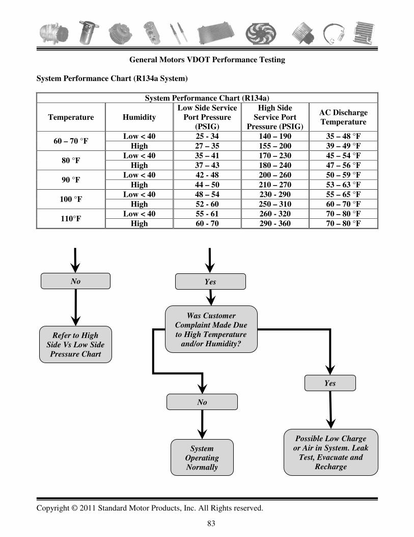
Copyright © 2011 Standard Motor Products, Inc. All Rights reserved.
83
General Motors VDOT Performance Testing
System Performance Chart (R134a System)
System Performance Chart (R134a)
Temperature Humidity
Low Side Service
Port Pressure
(PSIG)
High Side
Service Port
Pressure (PSIG)
AC Discharge
Temperature
60 – 70 °F Low < 40 25 - 34 140 – 190 35 – 48 °F
High 27 – 35 155 – 200 39 – 49 °F
80 °F Low < 40 35 – 41 170 – 230 45 – 54 °F
High 37 – 43 180 – 240 47 – 56 °F
90 °F Low < 40 42 - 48 200 – 260 50 – 59 °F
High 44 – 50 210 – 270 53 – 63 °F
100 °F Low < 40 48 – 54 230 - 290 55 – 65 °F
High 52 - 60 250 – 310 60 – 70 °F
110°F Low < 40 55 - 61 260 - 320 70 – 80 °F
High 60 - 70 290 - 360 70 – 80 °F
Yes No
Yes
System
Operating
Normally
Possible Low Charge
or Air in System. Leak
Test, Evacuate and
Recharge
No
Was Customer
Complaint Made Due
to High Temperature
and/or Humidity? Refer to High
Side Vs Low Side
Pressure Chart

Copyright © 2011 Standard Motor Products, Inc. All Rights reserved.
84
General Motors VDOT Performance Testing
High Side vs. Low Side Pressure Chart (R134a System)
High Side vs. Low Side Pressure Chart

Copyright © 2011 Standard Motor Products, Inc. All Rights reserved.
85
General Motors VDOT Performance Testing
Diagnosing Grey Chart Area (R134a System)
Check the following if pressures intersect in the grey area: Note: V5 Clutch cycling can occur when discharge pressure exceeds 400 PSI.
1. Improper condenser operation can
result from:
• Extremely high ambient humidity
• Insufficient air flow across the
condenser
• Damaged or dirty condenser fins
• Faulty fan relay
2. High side refrigerant restriction • Feel liquid line before the expansion
tube (orifice). If line feels cold, it
indicates restriction in the High side.
• Visually check for a frost spot to locate
restriction and repair as necessary.
3. Refrigerant system overcharged (high
discharge and high suction pressures). • The clutch may cycle on/off and cause
the compressor to be noisy. Refer to
number 5.
4. The clutch may cycle on/off and cause
the compressor to be noisy Refer to
number 5.
5. Air in system (high discharge and high
suction pressures). Items 4, 5, and 6 in
the striped area can be corrected by
the same procedure.
• Discharge refrigerant system slowly
using the low pressure fitting to prevent
oil loss.
• Check expansion (orifice) tube for
blockage. Clean or replace as required.
• Evacuate system. Improper system
evacuation, prior to recharging, will
allow air to remain in system.
• Recharge system with a proper amount
of refrigerant.
• Leak check system.

Copyright © 2011 Standard Motor Products, Inc. All Rights reserved.
86
General Motors VDOT Performance Testing
Diagnosing Striped Chart Area (R134a System)
Check the following if pressures intersect in the striped area:
1. Compressors may be internally
damaged • If suction and discharge pressure are
equal and do not change when the AC
mode is turned on and off, the
compressor may be internally damaged.
• Excess heat at the clutch surfaces or a
freewheeling clutch driver is a sign of
internal compressor damage.
• When replacing the compressor, follow
component replacement procedures to
maintain correct oil charge in the
system.
2. Missing expansion tube (orifice) • Feel liquid line after the expansion
tube. If the line is warm, discharge
system and inspect for proper
installation of the expansion tube. If the
expansion tube or o-ring is missing,
replace the expansion tube.
• If the expansion tube is present,
remove, clean, or replace the tube as
necessary and reinstall in the system.
• Evacuate and charge system.
3. Compressor running at minimum
displacement. • If the compressor discharge pressures
remain only 10-30 PSI above suction
pressure, the compressor may be at a
minimum stroke.
• Run the engine at approximately 3000
rpm for three minutes until pressures
become normal. During this period,
cycle the mode lever from vent to AC
every 20 seconds. If no change, perform
the control valve low load test (step 4).

Copyright © 2011 Standard Motor Products, Inc. All Rights reserved.
87
General Motors VDOT Performance Testing
Diagnosing Striped Chart Area (R134a System)
Check the following if pressures intersect in the striped area:
Note: These diagnostic flow chart examples are provided for the specific purpose of developing an
understanding of VDOT testing. Actual test procedures will vary by year and model vehicle.
Always refer to the OEM service manuals for the specific vehicle you are repairing or diagnosing.
4. Compressor control valves set
improperly. Run a low load test to
verify. Perform low load tests as
follows. This procedure is designed to
create a low cooling load causing the
V5 compressor to go toward a
minimum stroke which is absolutely
necessary for evaluation of control
valve-set points.
• Start engine and run at fast idle speed.
• Open hood, close windows and doors.
• Set AC controls to LOW speed, MAX
cooling.
• Record and evaluate test results:
• If suction pressure is 25-35 PSI, control
the valve is functioning properly.
• If suction pressure is outside limits of
25-35 PSI, replace the control valve.
5. Refrigerant system undercharged • This condition may exist when the
suction pressure is below 35 PSI during
the high load test (step 3).
• The suction line before the accumulator
will be warm if charge is low.
• Add 1 lb. Of refrigerant and recheck.
• Pressures should come into white area.
If so, find the source of refrigerant leak
and repair.
• Evacuate and charge system with the
correct amount or refrigerant.
6. Expansion tubes restriction • Refer to step 5 in the grey area for
diagnosis.

Copyright © 2011 Standard Motor Products, Inc. All Rights reserved.
88
GENERAL TROUBLE-SHOOTING PROCEDURES
Visual Check (engine off)
• Identify system type • Check system components and refrigerant lines for obvious damage (leaks or wear)
Gauge Hook-Up
• Install the correct gauge set (R12 or R134a) and check system pressure • If both gauges read 0 PSI the system is completely discharged • Evacuate the system • Charge with one pound of refrigerant • Leak test the system - if no leak is indicated - recharge the system before operating
Testing Conditions (engine running)
• Set engine speed at 1,500 - 1,700 rpm • Set AC controls to maximum cooling and high blower speed • Position a high volume fan in front of the condenser • Open all doors: Run the system for approximately 5 minutes, to stabilize the system • Close all doors • Set blower motor to low speed
Test Procedures
• Measure ambient temperature (2” in front of the condenser) Refer to the Pressure-Temperature relationship charts and determine normal readings
• Take readings from the high and the low side and record in worksheet • Test for heat transfer at the evaporator and the condenser • Check sight glass (if equipped) • Consult trouble-shooting charts for the system being serviced and follow recommended
procedures Caution: Prolonged operation in the test condition mode may cause dangerously high system
pressures due to poor air flow. Use only approved refrigerants such as R12 or R134a. Do not mix
refrigerants.

Copyright © 2011 Standard Motor Products, Inc. All Rights reserved.
89
CUSTOMER COMPLAINT WORKSHEET
Customer: ___________________________________________________________________________
Address: ____________________________________________________________________________
City: _______________________________________________________________________________
Home Phone: __________Work Phone: ____________ Mobile: ____________ Email: _____________
Vehicle Year: _______ Make: _________________ Model: ___________________Mileage: ________
CUSTOMER COMPLAINT
� No A/C
� Insufficient A/C
� Odors/Leaks (Describe):____________________________________________________________
� Drivability issue related to AC (Describe) ______________________________________________
� Other___________________________________________________________________________
When does the problem occur?
� All the time � Engine Cold � Engine hot � Other____________________________
Ambient temperature conditions when the problem occurs:
� All the time � 70°F - 90°F � 90°F and above � High temperature/High humidity
Vehicle operating conditions when the problem occurs:
� All the time � Idling � Cruising � Under load
Other ___________________________________________________________________________
SYSTEM FUNCTION TEST
Blower fan operation: � OK � No high blower � Missing speeds
� Other ____________________________________________________________________________
Air Distribution: � OK � No defrost � No panel � No floor � No recirculation
� Other ____________________________________________________________________________
Air Distribution: � OK � No defrost � No panel � No floor � No recirculation
� Other ____________________________________________________________________________
Customer comments: ____________________________________________________________________________________________________________________________________________________________________________________________________________________________________________________________

Copyright © 2011 Standard Motor Products, Inc. All Rights reserved.
90
DIAGNOSTIC & VISUAL INSPECTION WORKSHEET
Customer: ___________________________________________________________________________
Vehicle Year: _______ Make: _________________ Model: ___________________Mileage: ________
BASIC SYSTEM CHECKS
Radiator � Pass � Fail(Explain)_________________________
Condenser � Pass � Fail(Explain)_________________________
Condenser Design � Tube & Fin � Flat Tube
Condenser Flow � Serpentine Flow � Parallel Flow � Multipass Flow
Condenser Service � Needs Cleaning � Yes � No (Explain) ____________________________________________________________________________________
Hoses � Pass � Fail (Explain)______________________________________
Belts � Pass � Fail (Explain)______________________________________
Refrigerant Test: � R12 � R134a � R-1234yf � Blend � Contaminated � Percent Air
AC SYSTEM OPERATION
Computer Controls: Pass Fail (codes): � Pass � Fail ________________________________ AC Controls: Pass Fail (explain): � Pass � Fail________________________________ Compressor Operation: Pass Fail (explain): � Pass � Fail________________________________ Cooling Fan Operation: Pass Fail (explain): � Pass � Fail________________________________
AIR DISTRIBUTION SYSTEM OPERATION
Blower Operation: Pass Fail (explain): � Pass � Fail __________________________________ Air Distribution: Pass Fail (explain): � Pass � Fail__________________________________ Electronic Controls: Pass Fail (explain): � Pass � Fail__________________________________ Mechanical Controls: Pass Fail (explain): � Pass � Fail__________________________________
HEATER SYSTEM OPERATION
Heater Core: Pass Fail (explain): � Pass � Fail__________________________________
Heater Controls: Pass Fail (explain): � Pass � Fail__________________________________
TECHNICIAN COMMENTS: _________________________________________________________
____________________________________________________________________________________

Copyright © 2011 Standard Motor Products, Inc. All Rights reserved.
91
System Performance Test
Climate Conditions
Ambient Temperature _____________ Relative Humidity: � 30% � 60% � 90%
Refer to the Temperature Pressure Relationship chart, and record the maximum results you should expect from this system if it’s working properly at the above temperature.
Duct Temperature ____________ High Side Pressure ____________
Low-Side Pressure ____________ Auxiliary Pressure _____________
System Tests
• Install pressure gauges to the service ports — if there’s a second low-side port; install an
auxiliary gauge to that port as well.
• Start the engine, set the parking brake, and raise the idle to 2,000 RPM.
• Place a thermometer in the air conditioner center vent.
• Set the air conditioner for maximum cooling and high blower speed.
• Place a large fan in front of the condenser to force additional air past the condenser, in order to
simulate road test conditions.
• Close the doors and set the blower speed to low.
• Allow the system to operate for another five minutes before recording your readings.
Check the sight glass (if the system has one) � Clear � Bubbles � Foam
Check the A/C lines for frosting: Low-Side Lines: � OK � Frosted — indicates low refrigerant level correct this problem before continuing the test.
High-Side Lines: � OK � Frosted — indicates a restriction where the frost begins; correct this problem before continuing the test.
System Test Results
Duct Temperature ____________ High Side Pressure ____________
Low-Side Pressure ____________ Auxiliary Pressure _____________
• If temperatures and pressures are within specs, and the sight glass is clear, the system’s working
normally.
• If pressures are okay and the sight glass is clear, but duct temperature is high, check for a blend
door or heater control valve problem, or look for a possible system oil overcharge.
• If pressures vary from specs, perform the temperature test to locate the problem.

Copyright © 2011 Standard Motor Products, Inc. All Rights reserved.
92
Humidity / Temperature / Pressure Relationship
Engine Speed = 2000 RPM
R12 R134a
Relative
Humidity
%
Ambient
Air
Temp F
Maximum
Low Side
PSIG
Maximum
High Side
PSIG
Center
Duct
Air
Temp F
Maximum
Low Side
PSIG
Maximum
High Side
PSIG
Center
Duct
Air
Temp F 20% 70° 29 150 40° 37 225 46°
80° 29 190 44° 37 375 47° 90° 30 245 48° 37 325 53°
100° 31 305 57° 38 325 54° 30% 70° 29 150 42° 37 240 48°
80° 30 205 47° 37 285 50° 90° 31 265 51° 39 340 57°
100° 32 325 61° 43 360 60° 40% 70° 29 165 45° 37 260 49°
80° 30 215 49° 37 305 53° 90° 32 280 55° 42 355 60°
100° 39 345 65° 49 395 66° 50% 70° 30 180 47° 37 275 51°
80° 32 235 53° 39 320 56° 90° 34 295 59° 46 375 63°
100° 40 350 69° 55 430 72° 60% 70° 30 180 48° 37 290 53°
80° 33 240 56° 42 340 59° 90° 36 300 63° 49 390 66°
100° 43 360 73° 60 445 78°
70% 70° 30 180 50° 37 305 55° 80° 34 245 58° 45 355 62° 90° 38 305 65° 53 405 70°
80% 70° 30 190 50° 41 320 56° 80° 34 250 59° 48 370 65° 90° 39 310 67° 57 420 73°
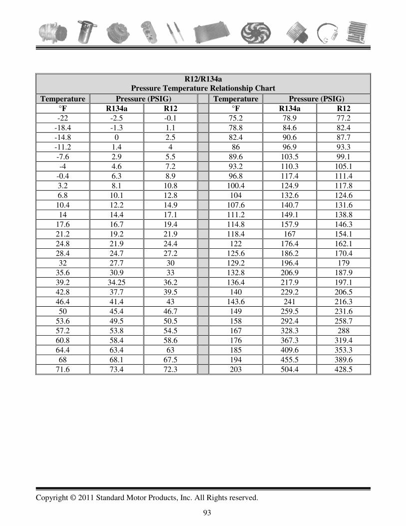
Copyright © 2011 Standard Motor Products, Inc. All Rights reserved.
93
R12/R134a
Pressure Temperature Relationship Chart
Temperature Pressure (PSIG) Temperature Pressure (PSIG)
°F R134a R12 °F R134a R12
-22 -2.5 -0.1 75.2 78.9 77.2 -18.4 -1.3 1.1 78.8 84.6 82.4 -14.8 0 2.5 82.4 90.6 87.7 -11.2 1.4 4 86 96.9 93.3 -7.6 2.9 5.5 89.6 103.5 99.1 -4 4.6 7.2 93.2 110.3 105.1
-0.4 6.3 8.9 96.8 117.4 111.4 3.2 8.1 10.8 100.4 124.9 117.8 6.8 10.1 12.8 104 132.6 124.6
10.4 12.2 14.9 107.6 140.7 131.6 14 14.4 17.1 111.2 149.1 138.8
17.6 16.7 19.4 114.8 157.9 146.3 21.2 19.2 21.9 118.4 167 154.1 24.8 21.9 24.4 122 176.4 162.1 28.4 24.7 27.2 125.6 186.2 170.4 32 27.7 30 129.2 196.4 179
35.6 30.9 33 132.8 206.9 187.9 39.2 34.25 36.2 136.4 217.9 197.1 42.8 37.7 39.5 140 229.2 206.5 46.4 41.4 43 143.6 241 216.3 50 45.4 46.7 149 259.5 231.6
53.6 49.5 50.5 158 292.4 258.7 57.2 53.8 54.5 167 328.3 288 60.8 58.4 58.6 176 367.3 319.4 64.4 63.4 63 185 409.6 353.3 68 68.1 67.5 194 455.5 389.6
71.6 73.4 72.3 203 504.4 428.5

Copyright © 2011 Standard Motor Products, Inc. All Rights reserved.
94
Reclaimed Refrigerant Contamination Chart R12 R134a
Temp °F Press (PSIG)
Temp °F Press (PSIG)
Temp °F Press (PSIG)
Temp °F Press (PSIG)
65 74 90 110 65 69 90 109 66 75 91 111 66 70 91 111 67 76 92 113 67 71 92 113 68 78 93 115 68 73 93 115 69 79 94 116 69 74 94 117 70 80 95 118 70 76 95 118 71 82 96 120 71 77 96 120 72 83 97 122 72 79 97 122 73 84 98 124 73 80 98 125 74 85 99 125 74 82 99 127 75 87 100 127 75 83 100 129 76 88 101 129 76 85 101 131 77 90 102 130 77 86 102 133 78 92 103 132 78 88 103 135 79 94 104 134 79 90 104 137 80 96 105 136 80 91 105 139 81 98 106 138 81 93 106 142 82 99 107 140 82 95 107 144 83 100 108 142 83 96 108 146 84 101 109 144 84 98 109 149 85 102 110 146 85 100 110 151 86 103 111 148 86 102 111 153 87 106 112 150 87 103 112 156 88 107 113 152 88 106 113 158 89 108 114 154 89 107 114 160

Copyright © 2011 Standard Motor Products, Inc. All Rights reserved.
95
Altitude Variations
The low pressure or compound gauge on the manifold gauge set has a vacuum scale reading in
inches of mercury. A gauge set can measure the vacuum accurately, but only at the elevation for
which the gauge is calibrated (sea level). At higher altitudes, the gauge will read low. AC
specifications are normally given in sea level terms, so at higher altitudes the gauge reading should
be corrected.
Altitude Vacuum Variations
Altitude (Ft. Above Sea
Level) Complete Vacuum (In. Hg.) Gauge Correction (In. Hg.)
0 29.92 0
1000 28.92 1
2000 27.82 2
3000 26.82 3.1
4000 25.82 4.1
5000 24.92 5
6000 23.92 6
7000 23.02 6.9
8000 22.22 7.7
9000 21.32 8.6
The chart below shows the boiling point of water at different vacuum levels.

Copyright © 2011 Standard Motor Products, Inc. All Rights reserved.
96
Maintain a temperature of 76ºF or higher, during the evacuation process, to ensure that all the
moisture is removed from the AC components. This can be accomplished, on cold days, by
running the engine and turning the heater on during the evacuation process. This will warm and
keep the components at a high enough temperature to vaporize the moisture.
Boiling Point Of Water At Specific Inches Of Vacuum
Boiling Point Of Water (°F) System Vacuum (inHg. @ Sea Level)
140 24.04
130 25.39
120 26.45
110 27.32
100 27.99
90 28.5
80 28.89
70 29.13
60 29.4
50 29.66
40 29.71
30 29.76
20 29.82
10 29.84
5 29.86
0 29.88
-10 29.9
-20 29.91
Micron Vacuum Versus Inches of Mercury Comparison Chart
% Vacuum (Percent) Microns Inches Mercury Gauge
0 760000 0
97.4 20000 29.14"
98.7 10000 29.53"
99 7600 29.62"
99.9 1000 29.88"
99.9 750 29.89"
99.99 100 29.916"
99.999 10 29.9196"

TEMPERATURE TESTING Single System Orifice Tube or
DIAGNOSTIC WORKSHEET Front Orifice Tube/Rear TXV Dual System
Copyright © 2011 Standard Motor Products, Inc. All Rights reserved.
97
VEHICLE
INFORMATION:
Year Make Model Engine Mileage Vin
SYSTEM CONFIGURATION
Condenser Type: Tube & Fin � Flat Tube � Sub-Cool � High Side Port Location
Refrigerant Flow: Serpentine Flow � Multi-Pass Flow � Discharge � Liquid Line �
Refrigerant Testing: Pure R12 � Pure 134a � Contaminated � % Air _____
Clutch Voltage Drop
AC Clutch (+) to (-) _______________
B(+) to B(-) __________
B(+) to Clutch (+) ______________
B(-) to Clutch (-) _____________
TEMPERATURE TESTING INFORMATION
Condenser Temperature Drop Rear Evaporator Superheat – Indirect Measurement (inlet inaccessible)
Condenser Inlet 20°F Minimum
50°F Maximum
Rear Duct Temperature Evaporator Outlet Should be Less than 10°F Warmer than Duct
Condenser Outlet Evaporator Outlet Line
Difference Difference
Front Evaporator Superheat System Performance – Rear Evaporator Inlet +/- 5°F OK
Ideal: 0°F Single -2°F Dual
Ambient Air Temp
Greater than 30°F
Outlet Rear Duct Temp.
Difference Difference
System Performance – Front Evaporator Front to Rear Duct Difference Less Than 4°F?
Ambient Air Temp
Greater than 30°F
Yes � No � Difference
Center Duct Temp. Low Side Pressure V. Rear Suction Line Temp.
Difference Pressure Temperature OK? * See Note
Rear Evaporator Superheat – Direct Measurement (inlet accessible) Yes � No � Inlet Line (After TXV)
Outlet +2°F
to +10°F
Warmer than Inlet
System Pressures Compressor Case Temperature
Evaporator Outlet Line High Side
Difference Low Side
* Note: If system correctly charged and low side pressure is low/normal but suction line temperature is high, suspect TXV valve malfunction – possible sticking, restricted.

TEMPERATURE TESTING
DIAGNOSTIC WORKSHEET Single or Dual TXV System
Copyright © 2011 Standard Motor Products, Inc. All Rights reserved.
98
VEHICLE
INFORMATION:
Year Make Model Engine Mileage Vin
SYSTEM CONFIGURATION
Condenser Type: Tube & Fin � Flat Tube � Sub-Cool � High Side Port Location
Refrigerant Flow: Serpentine Flow � Multi-Pass Flow � Discharge � Liquid Line �
Refrigerant Testing: Pure R12 � Pure 134a � Contaminated � % Air _____
Clutch Voltage Drop
AC Clutch (+) to (-) _______________
B(+) to B(-) _________
B(+) to Clutch (+) ______________
B(-) to Clutch (-) _____________
TEMPERATURE TESTING INFORMATION
Condenser Temperature Drop Front to Rear Duct Difference Less Than 4°F?
Condenser Inlet 20°F Minimum
50°F Maximum
Yes � No � Difference
Condenser Outlet Low Side Pressure V. Rear Suction Line Temp.
Difference Pressure Temperature OK? ** See Note
Evaporator Superheat - Direct Measurement (if inlet accessible) Yes � No � Inlet Front Rear
Outlet +2°F to +10°F Warmer
TXV System Charge Level – Use “TXV System Charge Level Chart “A” or “B”
Outlet
High Side Port Location
Discharge Line Use Chart A
Liquid Line Use Chart B
Difference High Side Pressure
Evaporator Superheat - Indirect Measurement (if inlet inaccessible)
Liquid Line Temperature
Outlet
Front Rear Outlet Should be Less than 10°F Warmer than Duct
Charge Level See Note*
Undercharged � Overcharged �
Duct Normal �
Difference *Note: Intersection of high side pressure and liquid line temperature on chart indicates system charge level.
System Performance
System Pressures Compressor Case Temperature Ambient Air Temp.
Front Rear
High Side
Duct Should be Greater than 30°F
Low Side
Difference **Note: If low side pressure low/normal but suction line temperature high – suspect TXV restriction or N.G.

Copyright © 2011 Standard Motor Products, Inc. All Rights reserved.
99
ABBREVIATIONS USED IN THE BOOK
12V 12 Volts ABDS Accessory Belt Drive System AC Air-conditioning ASHRAE American Society of Heating, Refrigerating and Air-Conditioning Engineers CAFÉ Corporate Average Fuel Economy CAT III Category 3 CCOT Cycling Clutch Orifice Tube CO2 (R744) Carbon Dioxide DMM Digital Multimeter DMM Digital Multimeter DTC Diagnostic Trouble Code EPA Environmental Protection Agency FFOT Ford Fixed Orifice Tube GHG Greenhouse Gas GWP Global Warming Potential HFC-134a Tetrafluoroethane HFO-1234yf 2,3,3,3-Tetrafluoropropene HV High Voltage HVAC Heating Ventilation & Air-conditioning inHg Inches of Mercury lb Pounds (weight) NCG Non Condensable Gas OE Original Equipment OT Orifice Tube oz Ounce PAG Polyalkylene Glycol PCM Powertrain Control Module PID Parameter Identification POE Polyolester (oil) PSI Pounds Per Square Inch R12 Dichlorodifluoromethane R-1234yf 2,3,3,3-Tetrafluoropropene R134a Tetrafluoroethane RPM Revolutions Per Minute SAE Society of Automotive Engineers SNAP Significant New Alternatives Policy TSB Technical Service Bulletin TXV Thermal Expansion Valve UV Ultraviolet VDOT Variable Displacement Orifice Tube

Copyright © 2011 Standard Motor Products, Inc. All Rights reserved.
100
Notes: