AHS International 68th Annual Forum & Technology … International 68th Annual Forum & Technology...
9
AHS International 68th Annual Forum & Technology Display Development of a Novel Erosion Resistant Coating System for Use on Rotorcraft Blades Matthew D. Trexler PhD Victor K. Champagne Team Leader, Innovative Materials & Processing Team US Army Research Laboratory (ARL) Army Research Laboratory Materials and Manufacturing Technology Branch RDRL-WMM-D BLDG 4600 Aberdeen Proving Ground, MD 21005-5069 Jack Kopchik, Sikorsky Aircraft Corp Abstract The costs associated with extended use of helicopters in erosive environments are well documented. Main and tail rotor blade erosion is among the leading drivers of a helicopter’s cost per flight hour. Improved polyurethane coatings provide a means to reduce these costs but require frequent touch up to prevent more severe damage. Furthermore, these coatings offer little protection from damage resulting from debris raised in the sand cloud generated during takeoffs and landings. An erosion resistant approach, developed in collaboration with AATD, ARL, United Technologies Research Center (UTRC) and Sikorsky utilizes a two part metal/cermet coating system on the leading edge of the blades to provide unmatched protection from sand, rain, and debris erosion. Tungsten carbide cobalt (WC-Co) is applied on the leading edge nose of the blade for direct impingement protection. Niobium is applied aft of the nose for indirect impingement protection. This paper will present techniques utilized to manage the process to meet the requirements of a fully functional coating without thermal damage to an expensive composite component. Introduction Current deployment of US Army UH-60 Blackhawk helicopter in desert environments has led to the observation of increased rotorblade erosion rates from the impingement of sand particles. Large efforts have been focusing on either improving the existing polyurethane coating performance and/or investigating alternative solutions. In 2008, AATD and Sikorsky entered into the rotor durability investment agreement to develop a protective system capable of withstanding 1,000 hours flight hours in a direct erosive environment (sand, rain, and debris). Additional requirements were that the system be implemented as replacements by spares option without any substantial redesign of the blade structure or loss of any other blade system functionality such as thermal deice.
Transcript of AHS International 68th Annual Forum & Technology … International 68th Annual Forum & Technology...
AHS International 68th Annual Forum & Technology Display
Development of a Novel Erosion Resistant Coating System for Use on Rotorcraft Blades
Matthew D. Trexler PhD
Victor K. Champagne Team Leader, Innovative Materials & Processing Team US Army Research Laboratory (ARL)
Army Research Laboratory Materials and Manufacturing Technology Branch
RDRL-WMM-D BLDG 4600 Aberdeen Proving Ground, MD 21005-5069
Jack Kopchik,
Sikorsky Aircraft Corp
Abstract The costs associated with extended use of helicopters in erosive environments are well documented. Main and tail rotor blade erosion is among the leading drivers of a helicopter’s cost per flight hour. Improved polyurethane coatings provide a means to reduce these costs but require frequent touch up to prevent more severe damage. Furthermore, these coatings offer little protection from damage resulting from debris raised in the sand cloud generated during takeoffs and landings.
An erosion resistant approach, developed in collaboration with AATD, ARL, United Technologies Research Center (UTRC) and Sikorsky utilizes a two part metal/cermet coating system on the leading edge of the blades to provide unmatched protection from sand, rain, and debris erosion. Tungsten carbide cobalt (WC-Co) is applied on the leading edge nose of the blade for direct impingement protection. Niobium is applied aft of the nose for indirect impingement protection. This paper will present techniques utilized to manage the process to meet the requirements of a fully functional coating without thermal damage to an expensive composite component.
Introduction
Current deployment of US Army UH-60 Blackhawk helicopter in desert environments has led to the observation of increased rotorblade erosion rates from the impingement of sand particles. Large efforts have been focusing on either improving the existing polyurethane coating performance and/or investigating alternative solutions. In 2008, AATD and Sikorsky entered into the rotor durability investment agreement to develop a protective system capable of withstanding 1,000 hours flight hours in a direct erosive environment (sand, rain, and debris). Additional requirements were that the system be implemented as replacements by spares option without any substantial redesign of the blade structure or loss of any other blade system functionality such as thermal deice.
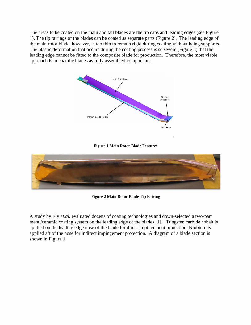
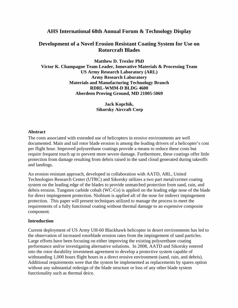
The areas to be coated on the main and tail blades are the tip caps and leading edges (see Figure 1). The tip fairings of the blades can be coated as separate parts (Figure 2). The leading edge of the main rotor blade, however, is too thin to remain rigid during coating without being supported. The plastic deformation that occurs during the coating process is so severe (Figure 3) that the leading edge cannot be fitted to the composite blade for production. Therefore, the most viable approach is to coat the blades as fully assembled components.
Figure 1 Main Rotor Blade Features
Figure 2 Main Rotor Blade Tip Fairing
A study by Ely et.al. evaluated dozens of coating technologies and down-selected a two-part metal/ceramic coating system on the leading edge of the blades [1]. Tungsten carbide cobalt is applied on the leading edge nose of the blade for direct impingement protection. Niobium is applied aft of the nose for indirect impingement protection. A diagram of a blade section is shown in Figure 1.
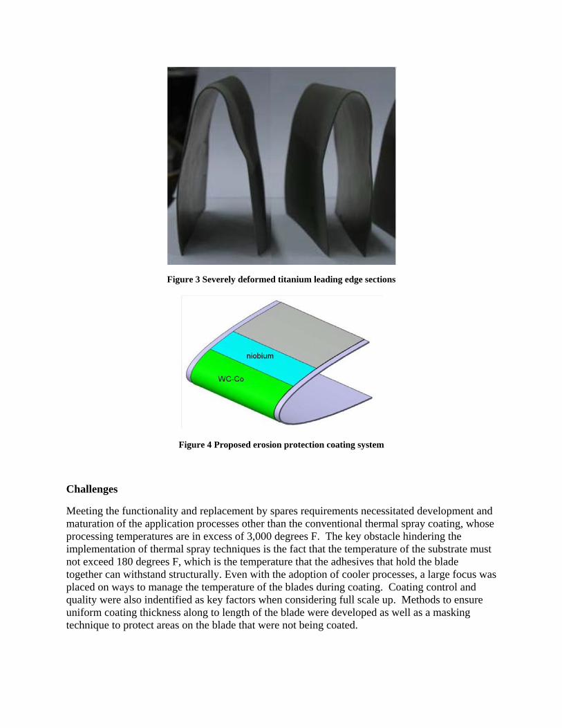
Figure 3 Severely deformed titanium leading edge sections
Figure 4 Proposed erosion protection coating system
Challenges
Meeting the functionality and replacement by spares requirements necessitated development and maturation of the application processes other than the conventional thermal spray coating, whose processing temperatures are in excess of 3,000 degrees F. The key obstacle hindering the implementation of thermal spray techniques is the fact that the temperature of the substrate must not exceed 180 degrees F, which is the temperature that the adhesives that hold the blade together can withstand structurally. Even with the adoption of cooler processes, a large focus was placed on ways to manage the temperature of the blades during coating. Coating control and quality were also indentified as key factors when considering full scale up. Methods to ensure uniform coating thickness along to length of the blade were developed as well as a masking technique to protect areas on the blade that were not being coated.
The techniques chosen to apply the coatings include a high velocity air fuel (HVAF) thermal spray technique and cold spray. These selections were based on the abilities of these processes to apply dense erosion resistant coatings with appropriate mechanical properties as to not adversely affect the overall fatigue life of the blades.
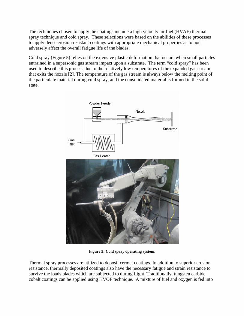
Cold spray (Figure 5) relies on the extensive plastic deformation that occurs when small particles entrained in a supersonic gas stream impact upon a substrate. The term “cold spray” has been used to describe this process due to the relatively low temperatures of the expanded gas stream that exits the nozzle [2]. The temperature of the gas stream is always below the melting point of the particulate material during cold spray, and the consolidated material is formed in the solid state.
Figure 5: Cold spray operating system.
Thermal spray processes are utilized to deposit cermet coatings. In addition to superior erosion resistance, thermally deposited coatings also have the necessary fatigue and strain resistance to survive the loads blades which are subjected to during flight. Traditionally, tungsten carbide cobalt coatings can be applied using HVOF technique. A mixture of fuel and oxygen is fed into
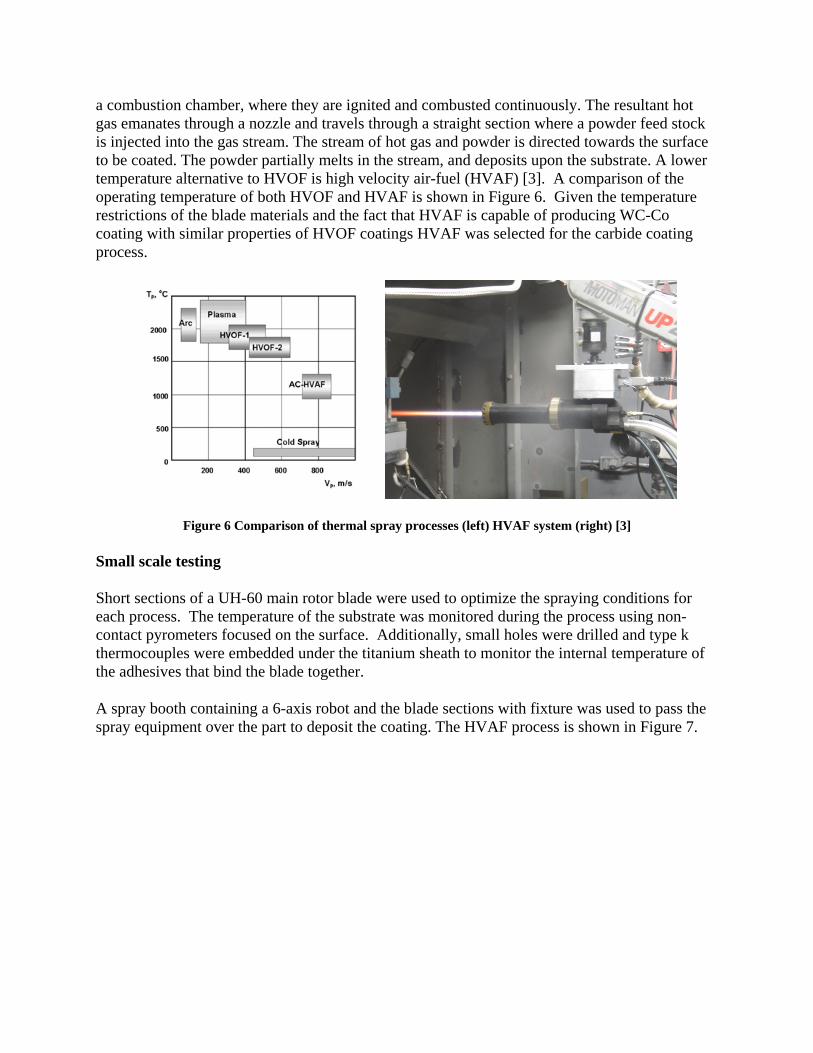
a combustion chamber, where they are ignited and combusted continuously. The resultant hot gas emanates through a nozzle and travels through a straight section where a powder feed stock is injected into the gas stream. The stream of hot gas and powder is directed towards the surface to be coated. The powder partially melts in the stream, and deposits upon the substrate. A lower temperature alternative to HVOF is high velocity air-fuel (HVAF) [3]. A comparison of the operating temperature of both HVOF and HVAF is shown in Figure 6. Given the temperature restrictions of the blade materials and the fact that HVAF is capable of producing WC-Co coating with similar properties of HVOF coatings HVAF was selected for the carbide coating process.
Figure 6 Comparison of thermal spray processes (left) HVAF system (right) [3]
Small scale testing
Short sections of a UH-60 main rotor blade were used to optimize the spraying conditions for each process. The temperature of the substrate was monitored during the process using non- contact pyrometers focused on the surface. Additionally, small holes were drilled and type k thermocouples were embedded under the titanium sheath to monitor the internal temperature of the adhesives that bind the blade together.
A spray booth containing a 6-axis robot and the blade sections with fixture was used to pass the spray equipment over the part to deposit the coating. The HVAF process is shown in Figure 7.
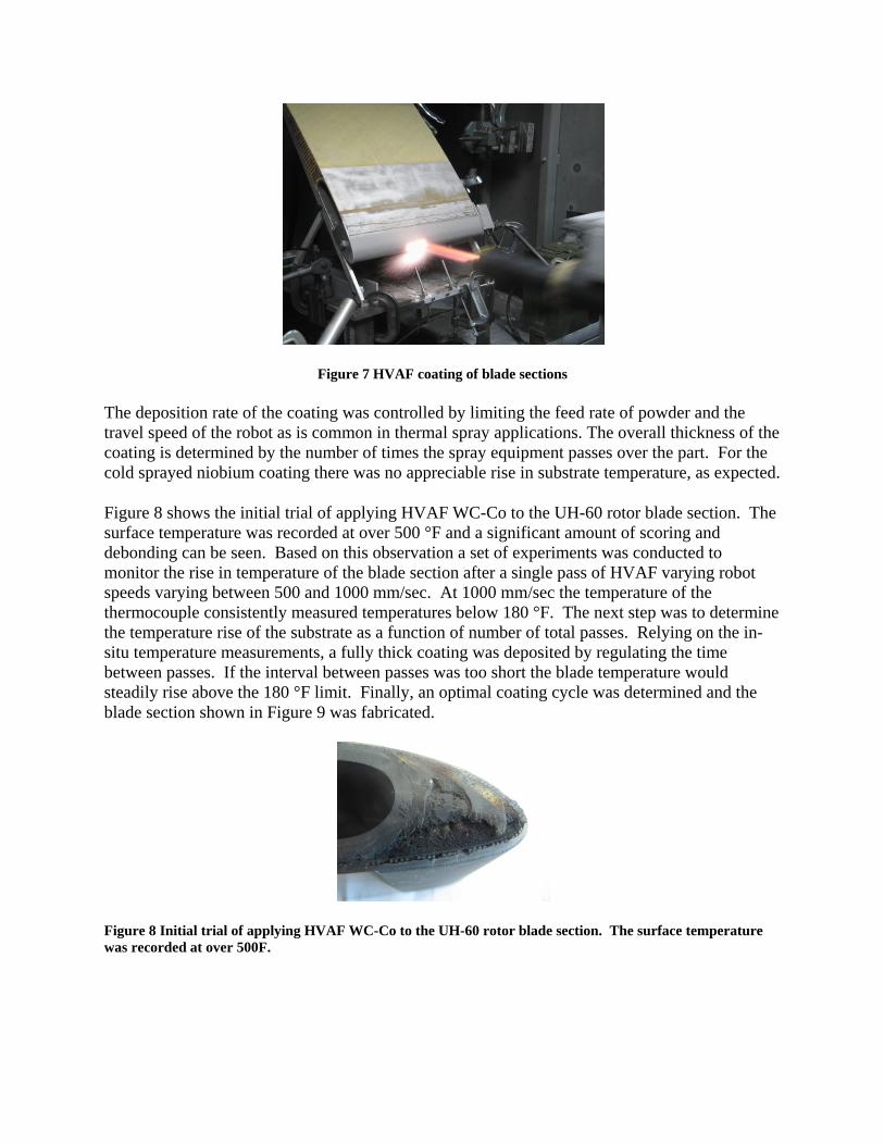
Figure 7 HVAF coating of blade sections
The deposition rate of the coating was controlled by limiting the feed rate of powder and the travel speed of the robot as is common in thermal spray applications. The overall thickness of the coating is determined by the number of times the spray equipment passes over the part. For the cold sprayed niobium coating there was no appreciable rise in substrate temperature, as expected.
Figure 8 shows the initial trial of applying HVAF WC-Co to the UH-60 rotor blade section. The surface temperature was recorded at over 500 °F and a significant amount of scoring and debonding can be seen. Based on this observation a set of experiments was conducted to monitor the rise in temperature of the blade section after a single pass of HVAF varying robot speeds varying between 500 and 1000 mm/sec. At 1000 mm/sec the temperature of the thermocouple consistently measured temperatures below 180 °F. The next step was to determine the temperature rise of the substrate as a function of number of total passes. Relying on the in-situ temperature measurements, a fully thick coating was deposited by regulating the time between passes. If the interval between passes was too short the blade temperature would steadily rise above the 180 °F limit. Finally, an optimal coating cycle was determined and the blade section shown in Figure 9 was fabricated.
Figure 8 Initial trial of applying HVAF WC-Co to the UH-60 rotor blade section. The surface temperature was recorded at over 500F.
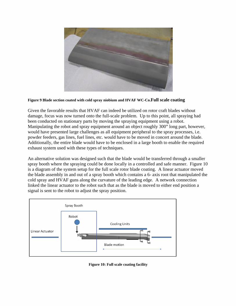
Figure 9 Blade section coated with cold spray niobium and HVAF WC-Co.Full scale coating
Given the favorable results that HVAF can indeed be utilized on rotor craft blades without damage, focus was now turned onto the full-scale problem. Up to this point, all spraying had been conducted on stationary parts by moving the spraying equipment using a robot. Manipulating the robot and spray equipment around an object roughly 300” long part, however, would have presented large challenges as all equipment peripheral to the spray processes, i.e. powder feeders, gas lines, fuel lines, etc. would have to be moved in concert around the blade. Additionally, the entire blade would have to be enclosed in a large booth to enable the required exhaust system used with these types of techniques.
An alternative solution was designed such that the blade would be transferred through a smaller spray booth where the spraying could be done locally in a controlled and safe manner. Figure 10 is a diagram of the system setup for the full scale rotor blade coating. A linear actuator moved the blade assembly in and out of a spray booth which contains a 6- axis root that manipulated the cold spray and HVAF guns along the curvature of the leading edge. A network connection linked the linear actuator to the robot such that as the blade is moved to either end position a signal is sent to the robot to adjust the spray position.
Figure 10: Full scale coating facility
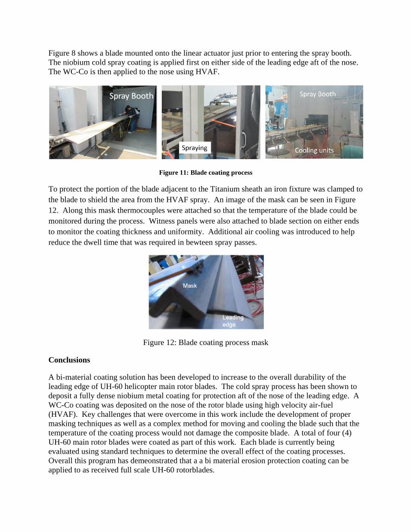
Figure 8 shows a blade mounted onto the linear actuator just prior to entering the spray booth. The niobium cold spray coating is applied first on either side of the leading edge aft of the nose. The WC-Co is then applied to the nose using HVAF.
Figure 11: Blade coating process
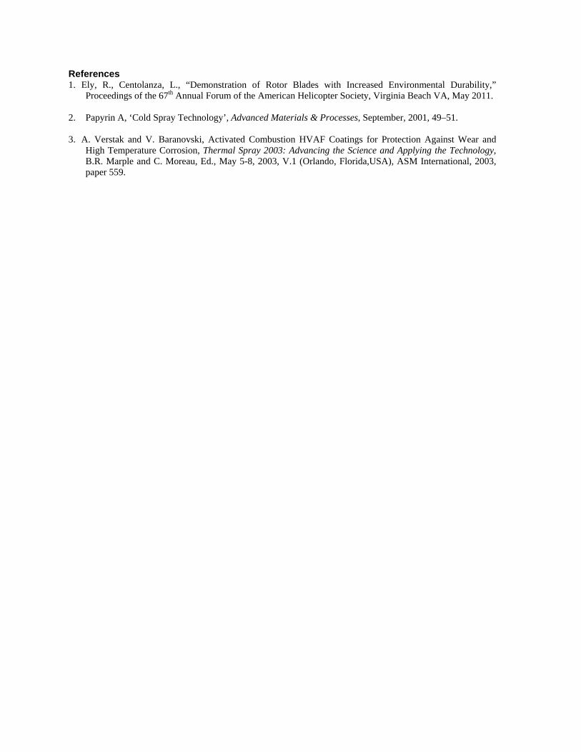
To protect the portion of the blade adjacent to the Titanium sheath an iron fixture was clamped to the blade to shield the area from the HVAF spray. An image of the mask can be seen in Figure 12. Along this mask thermocouples were attached so that the temperature of the blade could be monitored during the process. Witness panels were also attached to blade section on either ends to monitor the coating thickness and uniformity. Additional air cooling was introduced to help reduce the dwell time that was required in bewteen spray passes.
Figure 12: Blade coating process mask
Conclusions
A bi-material coating solution has been developed to increase to the overall durability of the leading edge of UH-60 helicopter main rotor blades. The cold spray process has been shown to deposit a fully dense niobium metal coating for protection aft of the nose of the leading edge. A WC-Co coating was deposited on the nose of the rotor blade using high velocity air-fuel (HVAF). Key challenges that were overcome in this work include the development of proper masking techniques as well as a complex method for moving and cooling the blade such that the temperature of the coating process would not damage the composite blade. A total of four (4) UH-60 main rotor blades were coated as part of this work. Each blade is currently being evaluated using standard techniques to determine the overall effect of the coating processes. Overall this program has demeonstrated that a a bi material erosion protection coating can be applied to as received full scale UH-60 rotorblades.
References 1. Ely, R., Centolanza, L., “Demonstration of Rotor Blades with Increased Environmental Durability,”
Proceedings of the 67th Annual Forum of the American Helicopter Society, Virginia Beach VA, May 2011.
2. Papyrin A, ‘Cold Spray Technology’, Advanced Materials & Processes, September, 2001, 49–51.
3. A. Verstak and V. Baranovski, Activated Combustion HVAF Coatings for Protection Against Wear and High Temperature Corrosion, Thermal Spray 2003: Advancing the Science and Applying the Technology, B.R. Marple and C. Moreau, Ed., May 5-8, 2003, V.1 (Orlando, Florida,USA), ASM International, 2003, paper 559.