AGZ Pump Packages In-Line Pumpslit.daikinapplied.com/bizlit/literature/lit_ch_ac/IMOM/... ·...
20
Installation, Operating and Maintenance Manual IOMM AGZ Pump Pkg Group: Chiller Part Number: 331680001 Date: June 2008 Supersedes: New AGZ Pump Packages In-Line Pumps 60 Hertz
-
Upload
trinhquynh -
Category
Documents
-
view
218 -
download
0
Transcript of AGZ Pump Packages In-Line Pumpslit.daikinapplied.com/bizlit/literature/lit_ch_ac/IMOM/... ·...
Installation, Operating and Maintenance Manual IOMM AGZ Pump Pkg
Group: Chiller
Part Number: 331680001
Date: June 2008
Supersedes: New
AGZ Pump Packages
In-Line Pumps 60 Hertz
2 IOMM AGZ Pump Pkg
Table of Contents
Introduction........................................3
General Description................................... 3 Inspection .................................................. 3
Installation and Start-up .....................3
Handling .................................................... 3 Service Access ........................................... 3 Vibration Isolators ..................................... 4 Field Water Piping..................................... 4 System Water Volume................................ 5 Freeze Protection....................................... 5
Component Location..........................6
Chilled Water Pump................................... 7 Expansion Tank ......................................... 7 Y Strainer.. Error! Bookmark not defined.
Triple-Duty Valve ................................ 8
Wiring Diagram ...............................14
Sequence of Operation .....................16
System Maintenance ........................17
General .................................................... 17 Lubrication .............................................. 17 Electrical Terminals................................. 17 Preventative Maintenance Schedule........ 17
Warranty Statement ..........................18
Service..............................................18
"McQuay" is a registered trademark of McQuay International 2008 McQuay International
Information covers the McQuay International products at the time of publication and we reserve the right to make changes in design and construction at anytime without notice.
Manufactured in an ISO Certified Facility
IOMM Pump Pkg 3
Introduction
General Description This manual provides information on optional pump packages factory mounted on McQuay Model
AGZ scroll compressor chillers. Operation of the chiller itself can be found in the appropriate manual
for the chiller.
Inspection When the equipment is received, carefully check all items against the bill of lading to check for a
complete shipment. Check all units for damage upon arrival. All shipping damage must be reported
to the carrier and a claim must be filed with the carrier. Check the unit’s serial plate before unloading
the unit to be sure that it agrees with the power supply available. Physical damage to unit after
acceptance is not the responsibility of McQuay International.
Installation and Start-up
Note: Installation and maintenance are to be performed only by qualified personnel who are familiar
with local codes and regulations, and experienced with this type of equipment.
Handling Avoid rough handling shock due to impact or dropping the unit. Do not push or pull the unit.
Never allow any part of the unit to fall during unloading or moving, as this can result in serious
damage.
To lift the unit, lifting tabs with 2½" (64 mm) diameter holes are provided on the base of the chiller
unit. All lifting holes must be used when lifting the unit. Spreader bars and cables should be
arranged to prevent damage to the condenser coils or unit cabinet.
DANGER
Improper lifting or moving unit can result in property damage, severe personal injury or death. Follow rigging and moving instructions carefully.
Service Access The control panel is located on the end of the unit. A minimum of four feet of clearance is required in
front of the panels. Allow a minimum of three feet on the other three sides.
WARNING
Disconnect, lockout and tag all power to the unit before servicing motors or compressors. Failure to do so can cause bodily injury or death
Do not block access to the sides or ends of the unit with piping or conduit. These areas must be open
for service access. Do not block any access to the control panels with a field-mounted disconnect
switches.
4 IOMM Pump Pkg
Vibration Isolators Vibration isolators are recommended for all roof-mounted installations or wherever
vibration transmission is a consideration. If the pump package is installed adjacent to a
chiller that is mounted on springs, it is essential that flexible piping connections be
employed between the two units.
Initially install the unit on shims or blocks at the illustrated "free height" of the isolator that
is six inches for the McQuay isolators shown. When all piping, wiring, flushing, charging,
etc. is complete, adjust the springs upward to load them and to provide clearance to free the
blocks, which are then removed.
Installation of spring isolators requires flexible pipe connections and at least three feet of
conduit flex tie-ins. Support piping and conduit independently from the unit to not stress
connections.
See the chiller unit installation manual for mounting hole locations.
Field Water Piping Due to the variety of piping practices, follow the recommendations of local authorities.
They can supply the installer with the proper building and safety codes required for a
proper installation.
Design the piping with a minimum number of bends and changes in elevation to keep
system cost down and performance up. It should contain:
1. Vibration eliminators to reduce vibration and noise transmission to the building.
2. Shutoff valves to isolate the unit from the piping system during unit servicing. The
pump package has suction and discharge service shutoff valves for each pump.
3. Manual or automatic air vent valves at the high points of the system and drains at the
low parts in the system. The evaporator should not be the highest point in the piping
system.
4. Some means of maintaining adequate system water pressure (i.e., expansion tank or
regulating valve).
5. Water temperature and pressure indicators located at the unit to aid in unit servicing.
6. A strainer to is provided in the package to remove foreign matter from the water before
it enters the pump and chiller. The use of a strainer will prolong pump life and help
maintain high system performance levels. The strainer must be cleaned after system
flushing is completed.
7. Any water piping to the unit must be protected to prevent freeze-up if below freezing
temperatures are expected.
8. If the unit is used with a replacement chiller on a previously existing piping system,
flush the system thoroughly prior to unit installation. Perform regular chilled water
analysis and chemical water treatment immediately at equipment start-up.
Make a preliminary leak check prior to insulating the water piping and filling the system.
Include a vapor barrier with the piping insulation to prevent moisture condensation and
possible damage to the building structure. It is important to have the vapor barrier on the
outside of the insulation to prevent condensation within the insulation on the cold surface
of the pipe.

IOMM Pump Pkg 5
System Water Volume It is important to have adequate water volume in the system to provide an opportunity for
the chiller to sense a load change, adjust to the change and stabilize. As the expected load
change becomes more rapid, a greater water volume is needed. The system water volume is
the total amount of water in the evaporator, air handling products and chilled water piping.
If the water volume is too low, operational problems can occur including rapid compressor
cycling, rapid loading and unloading of compressors, erratic refrigerant flow in the chiller,
improper motor cooling, shortened equipment life and other undesirable consequences.
For normal comfort cooling applications where the cooling load changes relatively slowly, a
minimum system volume of three minutes times the flow rate (gpm) is recommend. For
example, if the design chiller flow rate is 400 gpm, we recommend a minimum total system
volume of 1200 gallons (400 gpm x 3 minutes).
For process applications, such as a quenching tank, where the cooling load can change
rapidly, additional system water volume is needed. The load would be very stable until the
hot material is immersed in the water tank. Then, the load would increase drastically. For
this type of application, system volume can need to be increased.
Since there are many other factors that can influence performance, systems can successfully
operate below these suggestions. However, as the water volume decreases below these
suggestions, the possibility of problems increases.
Freeze Protection In installations where the unit is subject to sub-freezing temperatures, some method of
preventing pipe and component freezing and subsequent damage must be employed. The
pump package has an outdoor air thermostat (TH1) that will start the pump at 40°F to help
prevent freeze up. It is recommended that one or more of the following strategies also be
employed:
1. Drain the outdoor portion of the system and cap with a nitrogen charge.
2. Heat trace all outdoor components.
3. Add sufficient anti-freeze to prevent freezing.
Adding of a concentration of a glycol anti-freeze with a freeze point 10 degrees F below the
lowest expected outdoor temperature will result in decreased capacity and increased
pressure drop in the chiller. AGZ units are selected to provide the required capacity with
the fluid specified, water or antifreeze.
Note: Do not use automotive grade antifreezes as they contain inhibitors harmful to
chilled water systems. Use only glycols specifically designated for use in building
cooling systems.
6 IOMM Pump Pkg
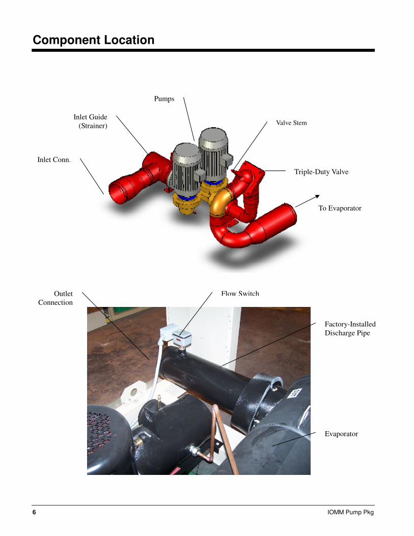
Component Location
Inlet Conn.
Inlet Guide
(Strainer)
Pumps
Triple-Duty Valve
Valve Stem
To Evaporator
Evaporator
Factory-Installed
Discharge Pipe
Flow Switch Outlet
Connection
IOMM Pump Pkg 7
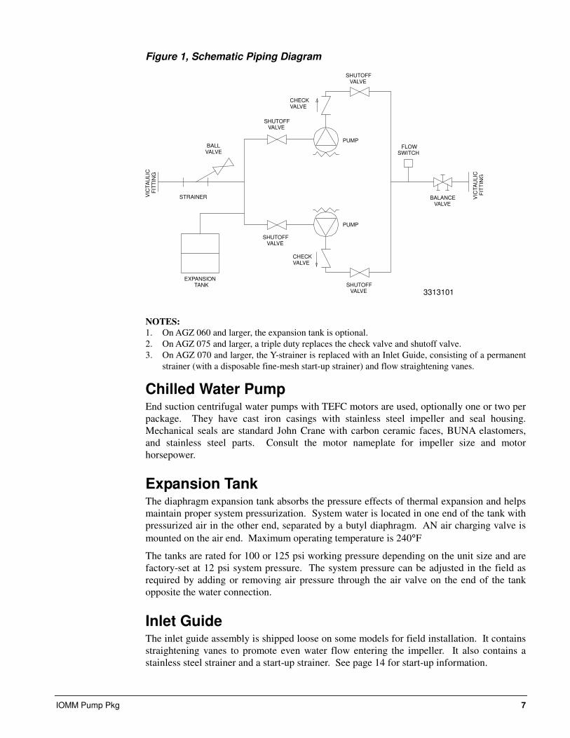
Figure 1, Schematic Piping Diagram
CHECKVALVE
CHECKVALVE
BALANCEVALVE
FLOWSWITCH
PUMP
PUMP
STRAINERVIC
TA
ULIC
FIT
TIN
G
VIC
TA
ULIC
FIT
TIN
G
EXPANSIONTANK
BALLVALVE
SHUTOFFVALVE
SHUTOFFVALVE
SHUTOFFVALVE
SHUTOFFVALVE
3313101
NOTES:
1. On AGZ 060 and larger, the expansion tank is optional.
2. On AGZ 075 and larger, a triple duty replaces the check valve and shutoff valve.
3. On AGZ 070 and larger, the Y-strainer is replaced with an Inlet Guide, consisting of a permanent
strainer (with a disposable fine-mesh start-up strainer) and flow straightening vanes.
Chilled Water Pump End suction centrifugal water pumps with TEFC motors are used, optionally one or two per
package. They have cast iron casings with stainless steel impeller and seal housing.
Mechanical seals are standard John Crane with carbon ceramic faces, BUNA elastomers,
and stainless steel parts. Consult the motor nameplate for impeller size and motor
horsepower.
Expansion Tank The diaphragm expansion tank absorbs the pressure effects of thermal expansion and helps
maintain proper system pressurization. System water is located in one end of the tank with
pressurized air in the other end, separated by a butyl diaphragm. AN air charging valve is
mounted on the air end. Maximum operating temperature is 240°F
The tanks are rated for 100 or 125 psi working pressure depending on the unit size and are
factory-set at 12 psi system pressure. The system pressure can be adjusted in the field as
required by adding or removing air pressure through the air valve on the end of the tank
opposite the water connection.
Inlet Guide The inlet guide assembly is shipped loose on some models for field installation. It contains
straightening vanes to promote even water flow entering the impeller. It also contains a
stainless steel strainer and a start-up strainer. See page 14 for start-up information.
8 IOMM Pump Pkg
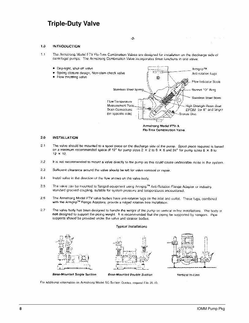
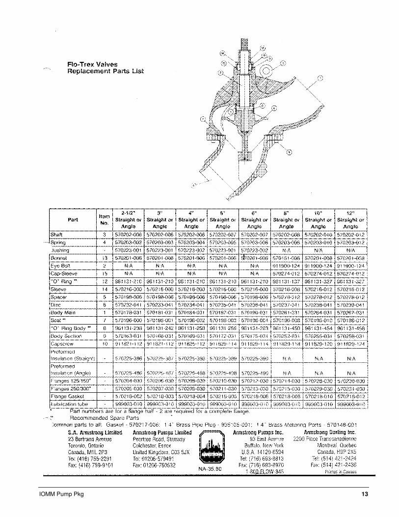
Triple-Duty Valve

IOMM Pump Pkg 9
10 IOMM Pump Pkg

IOMM Pump Pkg 11

12 IOMM Pump Pkg
IOMM Pump Pkg 13
14 IOMM Pump Pkg
Start-up
Follow the start-up procedure outlined in the chiller installation and operating manual. In
addition to that, check that the pump package is operating normally in accordance with its
sequence of operation.
Check rotation of the pump. It should be clockwise when viewing from the drive end,
looking from behind the motor.
Do not run the pump without fluid in the system. Fluid is required to cool and lubricate the
pump.
For in-line pumps, remove the temporary fine-mesh strainer from the inlet suction guide
after all debris has been removed from the system or after a maximum of 24 hours of
operation. Stop the pump, close the isolation valves, remove the drain plug or open the
blowdown valve. Remove the suction guide cover and the fine-mesh strainer, which is tack
welded to the permanent strainer. Replace the permanent strainer, O-ring and cover.
Failure to remove the temporary strainer can damage the pump.
IOMM Pump Pkg 15
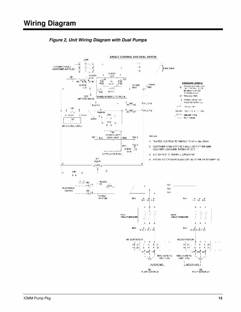
Wiring Diagram
Figure 2, Unit Wiring Diagram with Dual Pumps

16 IOMM Pump Pkg
Sequence of Operation
The pump package will start and stop automatically with the chiller unit. When the chiller
is enabled to run by having its MicroTech control in the Auto state or by a signal from a
BAS (not necessarily with compressors running based on availability of a cooling load), the
pump will receive a signal to start. When there is sufficient flow to close the flow switch
within a timed period (recirc timer), a proof-of-flow signal is sent to the chiller and the
pump is in the Run state. If there is a call for cooling based on the chilled water
temperature, the chiller will commence its compressor startup procedure. If there is no call
for cooling, the chiller will be on stand-by, waiting for load.
If the flow switch does not see flow, the pump remains in the Start state until flow is
established, at which time the pump will be in the Run state. Flow is recognized when the
flow switch indicates flow for longer than the recir timer setpoint.
The Run state is a control condition established by satisfying certain conditions. The Start
state means that a digital signal has been sent to the pump for it to start running.
If say, a chilled water valve is closed, the pump may receive a Start signal and will run
dead-headed but not actually be in the Run state as defined by the controller. No alarm is
given in this condition. When the valve is opened, the flow switch will see flow, will signal
this to the chiller controller, and the pump will go to the official Run state.
When starting the chiller, it is prudent to be sure there is flow so the chiller compressors
will be able to start based on a call for cooling due to high chilled water temperature.
Observing water pressure gauges can confirm flow.
On units with two pumps, the pump package’s alternating relay will alternate pump starts.
The pump control panel has a selector switch to provide AUTO (the alternating relay
determines which pump will run) and A or B pump (only pump A or only B will operate).
Flow interruption will open the flow switch, sending a signal to the chiller to shut down and
also de-energize the pump. If the chiller is turned off, the pump will shut off after a timed
period to allow water circulation during refrigerant pumpdown.
Operation of the evaporator pump is controlled by the state-transition diagram shown
below. Note that an outside air thermostat mounted on side of the pump panel will start the
pumps if freezing temperatures are approached.
Figure 3, Pump Transition Diagram
OFF
RUN START TEST: Flow OK for
Evap Recirc Time
TEST: Unit State=OFF & All
Comp State=OFF & NO Evap
water freeze condition
TEST: Unit State = AUTO AND At least
one circuit is enabled for start
OR
Evap water freeze condition
TEST: Unit State=OFF & All
Comp State=OFF & NO Evap
water freeze condition
Power ON

IOMM Pump Pkg 17
System Maintenance
General On initial start-up and periodically during operation, it will be necessary to perform certain
routine service checks. Among these are checking the liquid line sight glasses, and the
compressor oil level sight glass. In addition, check the MicroTech II controller temperature
and pressure readings with gauges and thermometers to see that the unit has normal
condensing and suction pressure and superheat and subcooling readings. A recommended
maintenance schedule is located at the end of this section.
Lubrication No routine lubrication is required on pump packages.
Electrical Terminals Electrical connections should be checked for tightness during initial startup and annually
thereafter.
DANGER
Electric equipment can cause electric shock with a risk of severe personal injury or
death. Turn off, lock out and tag all power before continuing with following service.
Panels can have more than one power source.
CAUTION Periodically check electrical terminals for tightness and tighten as required. Always
use a back-up wrench when tightening electrical terminals.
Preventative Maintenance Schedule PREVENTATIVE MAINTENANCE SCHEDULE
OPERATION WEEKLY MONTHLY
(Note 1)
ANNUAL
(Note 2)
General
Visually inspect unit for loose or damaged components and
visible leaks X
Inspect thermal insulation for integrity X
Clean and paint as required X
Electrical
Check contactors for pitting, replace as required X
Check terminals for tightness, tighten as necessary X
Clean control panel interior X
Visually inspect components for signs of overheating X
Notes:
1. Monthly operations include all weekly operations.
2. Annual (or spring start-up) operations include all weekly and monthly operations.

18 IOMM Pump Pkg
Warranty Statement
Limited Warranty
McQuay’s written Limited Product Warranty, along with any extended warranty expressly purchased is
the only warranty. Consult your local McQuay Representative for warranty details. Refer to Form
430285Y. To find your local McQuay Representative, go to www.mcquay.com.
Service
CAUTION
Service on this equipment must be performed by trained, experienced refrigeration
personnel familiar with equipment operation, maintenance, correct servicing
procedures, and the safety hazards inherent in this work. Causes for repeated
tripping of equipment protection controls must be investigated and corrected.
DANGER
Disconnect all power before doing any service inside the unit to avoid bodily injury or
death. MULTIPLE POWER SOURCES CAN FEED THE UNIT.


(800) 432-1342 • www.mcquay.com IOMM AGZ Pump Pkg (6/08)
This document contains the most current product information as of this printing. For the most up-to-date product information, please go to www.mcquay.com