PowerFlex 70 and 700 Packages for Fan and Pump Applications
134
PowerFlex 70 and 700 Packages for Fan and Pump Applications Catalog Numbers 21V, 21W Installation Instructions
-
Upload
tylerdurdane -
Category
Documents
-
view
13 -
download
0
description
PowerFlex 70 and 700 Packages for Fan and PumpApplications
Transcript of PowerFlex 70 and 700 Packages for Fan and Pump Applications

PowerFlex 70 and 700 Packages for Fan and Pump ApplicationsCatalog Numbers 21V, 21W
Installation Instructions

Important User Information
Read this document and the documents listed in the additional resources section about installation, configuration, and operation of this equipment before you install, configure, operate, or maintain this product. Users are required to familiarize themselves with installation and wiring instructions in addition to requirements of all applicable codes, laws, and standards.
Activities including installation, adjustments, putting into service, use, assembly, disassembly, and maintenance are required to be carried out by suitably trained personnel in accordance with applicable code of practice.
If this equipment is used in a manner not specified by the manufacturer, the protection provided by the equipment may be impaired.
In no event will Rockwell Automation, Inc. be responsible or liable for indirect or consequential damages resulting from the use or application of this equipment.
The examples and diagrams in this manual are included solely for illustrative purposes. Because of the many variables and requirements associated with any particular installation, Rockwell Automation, Inc. cannot assume responsibility or liability for actual use based on the examples and diagrams.
No patent liability is assumed by Rockwell Automation, Inc. with respect to use of information, circuits, equipment, or software described in this manual.
Reproduction of the contents of this manual, in whole or in part, without written permission of Rockwell Automation, Inc., is prohibited.
Throughout this manual, when necessary, we use notes to make you aware of safety considerations.
Labels may also be on or inside the equipment to provide specific precautions.
Allen-Bradley, Rockwell Software, Rockwell Automation, PowerFlex, and TechConnect are trademarks of Rockwell Automation, Inc.
Trademarks not belonging to Rockwell Automation are property of their respective companies.
WARNING: Identifies information about practices or circumstances that can cause an explosion in a hazardous environment, which may lead to personal injury or death, property damage, or economic loss.
ATTENTION: Identifies information about practices or circumstances that can lead to personal injury or death, property damage, or economic loss. Attentions help you identify a hazard, avoid a hazard, and recognize the consequence.
IMPORTANT Identifies information that is critical for successful application and understanding of the product.
SHOCK HAZARD: Labels may be on or inside the equipment, for example, a drive or motor, to alert people that dangerous voltage may be present.
BURN HAZARD: Labels may be on or inside the equipment, for example, a drive or motor, to alert people that surfaces may reach dangerous temperatures.
ARC FLASH HAZARD: Labels may be on or inside the equipment, for example, a motor control center, to alert people to potential Arc Flash. Arc Flash will cause severe injury or death. Wear proper Personal Protective Equipment (PPE). Follow ALL Regulatory requirements for safe work practices and for Personal Protective Equipment (PPE).

Summary of Changes
This manual contains new and updated information.
New and Updated Information
This table contains the changes made to this revision.
Topic Page
Updated the Catalog Number Explanation (Interbus and Remote I/O communication options, and style C packages, are no longer available for sale)
9
Main Input Disconnect Package (style A)
Updated AC input power terminal block specifications (style A) 14
Updated layout drawings to show new input power terminal block (style A) 30
Updated outline drawings to show new disconnect switch/operator handle (style A) 40
Updated replacement part numbers (style A) for some of these parts: disconnect switch, operator handle, and operator shaft.
119
Three-contactor Full-feature Bypass with Disconnect Package (style B)
Updated AC input power terminal block specifications (style B) 57
Updated layout drawings to show new input power terminal block (style B) 86
Updated outline drawings to show new disconnect switch/operator handle (style B) 95
Updated replacement part numbers and horsepower ratings (style B) for some of these parts: disconnect switch, operator handle, operator shaft, bypass contactor, drive input contactor, drive output contactor, and overload relay.
123
Removed all style C packages (style C packages are no longer available for sale). –
Added Fuse, Circuit Breaker, and Short Circuit Current Specifications 117
Added an index to this manual. 131
Rockwell Automation Publication 21VW-IN001D-EN-P - July 2013 3

Summary of Changes
Notes:
4 Rockwell Automation Publication 21VW-IN001D-EN-P - July 2013

Table of Contents
Preface About This Publication. . . . . . . . . . . . . . . . . . . . . . . . . . . . . . . . . . . . . . . . . . . . . 7What Is Not in This Manual . . . . . . . . . . . . . . . . . . . . . . . . . . . . . . . . . . . . . . . . 7Manual Conventions . . . . . . . . . . . . . . . . . . . . . . . . . . . . . . . . . . . . . . . . . . . . . . . 7General Precautions . . . . . . . . . . . . . . . . . . . . . . . . . . . . . . . . . . . . . . . . . . . . . . . . 8Catalog Number Explanation . . . . . . . . . . . . . . . . . . . . . . . . . . . . . . . . . . . . . . . 9Additional Resources . . . . . . . . . . . . . . . . . . . . . . . . . . . . . . . . . . . . . . . . . . . . . 10Technical Support . . . . . . . . . . . . . . . . . . . . . . . . . . . . . . . . . . . . . . . . . . . . . . . 10
Chapter 1Main Input Disconnect Package(style A)
Hardware Overview . . . . . . . . . . . . . . . . . . . . . . . . . . . . . . . . . . . . . . . . . . . . . . 11Electrical Installation . . . . . . . . . . . . . . . . . . . . . . . . . . . . . . . . . . . . . . . . . . . . . 13Parameter Defaults . . . . . . . . . . . . . . . . . . . . . . . . . . . . . . . . . . . . . . . . . . . . . . . 17Drawing Index . . . . . . . . . . . . . . . . . . . . . . . . . . . . . . . . . . . . . . . . . . . . . . . . . . . 21Schematic Drawings . . . . . . . . . . . . . . . . . . . . . . . . . . . . . . . . . . . . . . . . . . . . . . 24Inter-connect Drawings . . . . . . . . . . . . . . . . . . . . . . . . . . . . . . . . . . . . . . . . . . 27Layout Drawings . . . . . . . . . . . . . . . . . . . . . . . . . . . . . . . . . . . . . . . . . . . . . . . . . 30Outline Drawings . . . . . . . . . . . . . . . . . . . . . . . . . . . . . . . . . . . . . . . . . . . . . . . . 40
Chapter 2Three-contactor Full-feature Bypass with Disconnect Package(style B)
Hardware Overview . . . . . . . . . . . . . . . . . . . . . . . . . . . . . . . . . . . . . . . . . . . . . . 51Electrical Installation . . . . . . . . . . . . . . . . . . . . . . . . . . . . . . . . . . . . . . . . . . . . . 57Customer Connections . . . . . . . . . . . . . . . . . . . . . . . . . . . . . . . . . . . . . . . . . . . 61Operating Modes . . . . . . . . . . . . . . . . . . . . . . . . . . . . . . . . . . . . . . . . . . . . . . . . 62Parameter Defaults . . . . . . . . . . . . . . . . . . . . . . . . . . . . . . . . . . . . . . . . . . . . . . . 64Drawing Index . . . . . . . . . . . . . . . . . . . . . . . . . . . . . . . . . . . . . . . . . . . . . . . . . . . 68Schematic Drawings . . . . . . . . . . . . . . . . . . . . . . . . . . . . . . . . . . . . . . . . . . . . . . 71Inter-connect Drawings . . . . . . . . . . . . . . . . . . . . . . . . . . . . . . . . . . . . . . . . . . 83Layout Drawings . . . . . . . . . . . . . . . . . . . . . . . . . . . . . . . . . . . . . . . . . . . . . . . . . 86Outline Drawings . . . . . . . . . . . . . . . . . . . . . . . . . . . . . . . . . . . . . . . . . . . . . . . . 95
Chapter 3Mechanical Installation Mounting Considerations . . . . . . . . . . . . . . . . . . . . . . . . . . . . . . . . . . . . . . . 107
Lifting and Mounting the Drive . . . . . . . . . . . . . . . . . . . . . . . . . . . . . . . . . . 108Watts Loss . . . . . . . . . . . . . . . . . . . . . . . . . . . . . . . . . . . . . . . . . . . . . . . . . . . . . 109Weights . . . . . . . . . . . . . . . . . . . . . . . . . . . . . . . . . . . . . . . . . . . . . . . . . . . . . . . . 111
Appendix ATechnical Specifications Environmental Specifications . . . . . . . . . . . . . . . . . . . . . . . . . . . . . . . . . . . . 117
Fuse, Circuit Breaker, and Short Circuit Current Specifications. . . . . 117
Rockwell Automation Publication 21VW-IN001D-EN-P - July 2013 5

Table of Contents
Appendix BReplacement Parts Main Input Disconnect Package (style A) . . . . . . . . . . . . . . . . . . . . . . . . . 119
Three-contactor Full-feature Bypass with Disconnect Package(style B) . . . . . . . . . . . . . . . . . . . . . . . . . . . . . . . . . . . . . . . . . . . . . . . . . . . . . . . . 123
Index . . . . . . . . . . . . . . . . . . . . . . . . . . . . . . . . . . . . . . . . . . . . . . . . . . . . . . . . . . . . . . . . 131
6 Rockwell Automation Publication 21VW-IN001D-EN-P - July 2013

Preface
The purpose of this manual is to provide basic installation and operation information for PowerFlex® 70 and 700 packages for fan and pump applications.
These additional manuals are required to properly install and operate the PowerFlex 70 and 700 packages for fan and pump applications:
• PowerFlex 70 Adjustable Frequency AC Drives User Manual, publication 20A-UM001
• PowerFlex 700 Adjustable Frequency AC Drives User Manual, publication 20B-UM001.
About This Publication This manual is intended for qualified personnel. You must be able to program and operate adjustable frequency AC drives. In addition, you must have an understanding of the parameter settings and functions.
What Is Not in This Manual This manual is intended to provide basic installation and operation information. For this reason, the following topics have not been included in this manual:
• Specifications• Troubleshooting• Starting• Programming and parameters
Refer to the PowerFlex 70 Adjustable Frequency AC Drives User Manual, publication 20A-UM001, or the PowerFlex 700 Adjustable Frequency AC Drive User Manual, publication 20B-UM001, for detailed information including specifications, troubleshooting, starting, programming, and parameters for the drives.
Manual Conventions To help differentiate parameter names and liquid crystal display (LCD) text from other text, the following conventions are used:
• Parameter Names appear in [brackets]. For example: [DC Bus Voltage].
• Display Text appears in “quotes.”For example: “Enabled.”
Topic Page
About This Publication 7
What Is Not in This Manual 7
Manual Conventions 7
General Precautions 8
Catalog Number Explanation 9
Additional Resources 10
Technical Support 10
Rockwell Automation Publication 21VW-IN001D-EN-P - July 2013 7

Preface
General PrecautionsATTENTION: This drive contains ESD (Electrostatic Discharge) sensitive parts and assemblies. Static control precautions are required when installing, testing, servicing, or repairing this assembly. Component damage can result if ESD control procedures are not followed. If you are not familiar with static control procedures, reference A-B publication 8000-4.5, “Guarding Against Electrostatic Damage” or any other applicable ESD protection handbook.
ATTENTION: An incorrectly applied or installed drive can result in component damage or a reduction in product life. Wiring or application errors, such as undersizing the motor, incorrect or inadequate AC supply, or excessive ambient temperatures can result in malfunction of the system.
ATTENTION: Only qualified personnel familiar with adjustable frequency AC drives and associated machinery should plan or implement the installation, startup, and subsequent maintenance of the system. Failure to comply can result in personal injury and/or equipment damage.
ATTENTION: To avoid an electric shock hazard, verify that the voltage on the bus capacitors has discharged before performing any work on the drive. Measure the voltage at the drive (Refer to the PowerFlex 70 Adjustable Frequency AC Drives User Manual, publication 20A-UM001, or the PowerFlex 700 Adjustable Frequency AC Drive User Manual, publication 20B-UM001, for test point locations). The voltage must be zero.
8 Rockwell Automation Publication 21VW-IN001D-EN-P - July 2013

Preface
Catalog Number Explanation �e PowerFlex 70 and 700 packages for fan and pump applications catalog numbering scheme is shown below.
Position
1-3 4 5-7 8 9 10 11 12 13 14 15 16 17 18 19
21V D 2P1 A 3 A Y N A E C 0 B N - LRa b c d e f g h i j k l m n o
aDrive
Code Type
21V PowerFlex 70 Drive
21W PowerFlex 700 Drive
bVoltage Rating
Code Voltage Ph.
X 208V AC 3
D 480V AC 3
E 600V AC 3
c1ND Rating
208V, 60Hz Input
Code Amps Frame kW (Hp)
4P2 4.8 B 0.75 (1.0)
6P8 7.8 B 1.5 (2.0)
9P6 11 B 2.2 (3.0)
015 17.5 C 4.0 (5.0)
022 25.3 D 5.5 (7.5)
028 32.2 D 7.5 (10)
042 43 D 11 (15)
c2ND Rating
480V, 60Hz Input
Code Amps Frame kW (Hp)
2P1 * 2.1 B 0.75 (1.0)
3P4 * 3.4 B 1.5 (2.0)
5P0 * 5.0 B 2.2 (3.0)
8P0 * 8.0 B 4.0 (5.0)
011 * 11 C 5.5 (7.5)
014 * 14 C 7.5 (10)
022 * 22 D 11 (15)
027 * 27 D 15 (20)
034 * 34 D 18.5 (25)
040 * 40 D 22 (30)
065 * 65 E 37 (50)
052 * 52 E 30 (40)
077 § 77 4 45 (60)
096 § 96 5 55 (75)
125 § 125 5 75 (100)
156 § 156 6 90 (125)
180 § 180 6 110 (150)
248 § 248 6 132 (200)
§ PowerFlex 700 options only.* PowerFlex 70 options only.
c3ND Rating
600V, 60Hz Input
Code Amps Frame kW (Hp)
3P9 * 3.9 B 2.2 (3.0)
6P1 * 6.1 B 4.0 (5.0)
9P0 * 9.0 C 5.5 (7.5)
011 * 11 C 7.5 (10)
017 * 17 D 11 (15)
022 * 22 D 15 (20)
027 * 27 D 18.5 (25)
032 * 32 D 22 (30)
041 * 41 E 30 (40)
052 * 52 E 37 (50)
062 § 62 4 45 (60)
077 § 77 5 55 (75)
099 § 99 5 75 (100)
125 § 125 6 90 (125)
144 § 144 6 110 (150)
dEnclosure
Code Enclosure
A IP 20, NEMA Type 1
eHIM
Code Operator Interface
0 Blank Cover
2 Digital LCD
3 Full Numeric LCD
5 Prog. Only LCD
fDocumentation
Code Type
A User Manual
gBrake IGBT
Code w/Brake IGBT
seYY
N § No
Brake IGBT is standard on PowerFlex 70Frames B, C, D and E, and optional onPowerFlex 700 Frames 4, 5 and 6.
§ PowerFlex 700 options only.
hInternal Brake Resistor
Code w/Resistor
Y Yes
oNN
Brake resistor only available for PowerFlex 70:208V Frames B, C & D, 480V Frames B, C & D,600V Frames B and C.
iEmission
Code CE Filter
seYA
N No
PowerFlex 70 600V ratings only.
jComm Slot
Code Version
B BACnet
C ControlNet (Coax)
D DeviceNet
E EtherNet/IP
H RS-485 HVAC
L LonWorks
P PROFIBUS DP
Q ControlNet (Fiber)
S RS-485 DF1
N None
kControl & I/O
Code Control I/O Volts
A Standard 24V DC/AC
C Enhanced 24V DC
PowerFlex 700 options only.
PowerFlex 70 options only.
lFeedback
Code Feedback
0 None
mPackage
Code Description
A Main Input Disconnect
B3 Contactor Full
Feature Bypass withDisconnect
n
Reserved
oOptions
Code Description
LR Input Line Reactor
Only available with Package Code A and Bdrives 1.0…10 HP @ 208V, 1.0…25 Hp @ 480Vand 3.0…25 HP @ 600V.
§ PowerFlex 700 options only.* PowerFlex 70 options only.
R * Remote I/O
InterbusI *
The comm slot option is no longer available for sale.
C *3 Contactor Basic
Bypass withDisconnect
The style C package is no longer available for sale.
Rockwell Automation Publication 21VW-IN001D-EN-P - July 2013 9

Preface
Additional Resources These documents contain additional information concerning related products from Rockwell Automation.
You can view or download publications athttp:/www.rockwellautomation.com/literature/. To order paper copies of technical documentation, contact your local Allen-Bradley distributor or Rockwell Automation sales representative.
Technical Support For technical support contact information, see Rockwell Automation Support on the back cover.
Resource Description
PowerFlex 70 Adjustable Frequency User Manual, publication 20A-UM001 Provides the basic information needed to install, start, and
troubleshoot the PowerFlex 70 and 700 drives.PowerFlex 700 Adjustable Frequency AC Drive User Manual, publication 20B-UM001
PowerFlex 70 & 700 Adjustable Frequency AC Drive Reference Manual, publication PFLEX-RM001 Provides specification and operation details for the
PowerFlex 70 and 700 drives.PowerFlex 70 Enhanced Control and 700 Vector Control Reference Manual, publication PFLEX-RM004
Industry Installation Guidelines for Pulse Width Modulated (PWM) AC Drives, publication DRIVES-AT003
Provides basic information for enclosure systems and environmental/location considerations (to help protect against environmental contaminants), and power and grounding considerations needed to properly install AC drives.
Wiring and Grounding Guidelines for Pulse Width Modulated (PWM) AC Drives, publication DRIVES-IN001
Provide the basic information needed to properly wire and ground pulse width modulated (PWM) AC drives.
Preventive Maintenance of Industrial Control and Drive System Equipment, publication DRIVES-TD001
Provides a checklist as a guide for preventive maintenance of industrial control and drive equipment.
Safety Guidelines for the Application, Installation and Maintenance of Solid State Control, publication SGI-1.1
Provides general guidelines for the application, installation, and maintenance of solid-state control with an emphasis on personnel safety.
A Global Reference Guide for Reading Schematic Diagrams, publication 100-2.10
Provides a simple cross-reference of common schematic/wiring diagram symbols used throughout various parts of the world.
Guarding Against Electrostatic Damage, publications 8000-4.5
Provides an overview of the causes of electrostatic discharge (ESD), and how you can guard against the damage caused by ESD.
Industrial Automation Wiring and Grounding Guidelines, publication 1770-4.1
Provides general guidelines for installing a Rockwell Automation industrial system.
Product Certifications website, http://www.ab.com Provides declarations of conformity, certificates, and other certification details.
10 Rockwell Automation Publication 21VW-IN001D-EN-P - July 2013

Chapter 1
Main Input Disconnect Package (style A)
This chapter describes the features and operation for the main input disconnect package (style A).
Hardware Overview The main input disconnect package (style A) combines an adjustable frequency AC drive with a means for disconnecting input power within a single package. Input power is connected to the PowerFlex drive through a door interlocked fuse disconnect switch.
Main Disconnect Switch (DS1)
An Allen-Bradley Bulletin 194R fused disconnect switch with lockable rotary mounted operator handle is provided. The disconnect switch is designed to meet disconnect switch requirements for branch circuit protection. The door-mounted handle accepts up to three padlocks.
Main Fuses (FU1…FU3)
Input line branch circuit protection fuses must be used to protect the input power lines. If input fuses are not provided with your drive, recommended fuse values are shown in Table 1 on page 12. The input fuse ratings listed in Table 1 on page 12 are applicable for one drive per branch circuit. Do not apply other loads to the fused circuit.
Topic Page
Hardware Overview 11
Electrical Installation 13
Parameter Defaults 17
Drawing Index 21
Schematic Drawings 24
Inter-connect Drawings 27
Layout Drawings 30
Outline Drawings 40
ATTENTION: Most codes require that upstream branch circuit protection be provided to protect input power wiring. Install the fuses recommended in Table 1 on page 12. Do not exceed the fuse ratings. Failure to observe this precaution could result in damage to, or destruction of, the equipment.
Rockwell Automation Publication 21VW-IN001D-EN-P - July 2013 11

Chapter 1 Main Input Disconnect Package (style A)
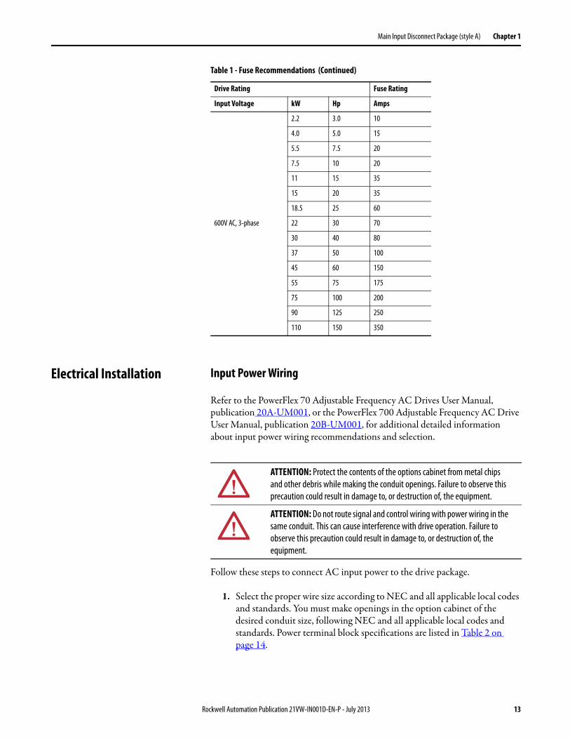
The recommended fuse type for all PowerFlex 70 and 700 packages for fan and pump applications is UL Class J, 600V. Table 1 - Fuse Recommendations
Drive Rating Fuse Rating
Input Voltage kW Hp Amps
208V AC, 3-phase
0.75 1.0 10
1.5 2.0 15
2.2 3.0 20
4.0 5.0 20
5.5 7.5 35
7.5 10 40
11 15 80
480V AC, 3-phase
0.75 1.0 6.0
1.5 2.0 10
2.2 3.0 10
4.0 5.0 15
5.5 7.5 20
7.5 10 20
11 15 35
15 20 35
18.5 25 60
22 30 70
30 40 80
37 50 100
45 60 150
55 75 175
75 100 200
90 125 250
110 150 350
132 200 400
12 Rockwell Automation Publication 21VW-IN001D-EN-P - July 2013
Main Input Disconnect Package (style A) Chapter 1
Electrical Installation Input Power Wiring
Refer to the PowerFlex 70 Adjustable Frequency AC Drives User Manual, publication 20A-UM001, or the PowerFlex 700 Adjustable Frequency AC Drive User Manual, publication 20B-UM001, for additional detailed information about input power wiring recommendations and selection.
Follow these steps to connect AC input power to the drive package.
1. Select the proper wire size according to NEC and all applicable local codes and standards. You must make openings in the option cabinet of the desired conduit size, following NEC and all applicable local codes and standards. Power terminal block specifications are listed in Table 2 on page 14.
600V AC, 3-phase
2.2 3.0 10
4.0 5.0 15
5.5 7.5 20
7.5 10 20
11 15 35
15 20 35
18.5 25 60
22 30 70
30 40 80
37 50 100
45 60 150
55 75 175
75 100 200
90 125 250
110 150 350
Table 1 - Fuse Recommendations (Continued)
Drive Rating Fuse Rating
Input Voltage kW Hp Amps
ATTENTION: Protect the contents of the options cabinet from metal chips and other debris while making the conduit openings. Failure to observe this precaution could result in damage to, or destruction of, the equipment.
ATTENTION: Do not route signal and control wiring with power wiring in the same conduit. This can cause interference with drive operation. Failure to observe this precaution could result in damage to, or destruction of, the equipment.
Rockwell Automation Publication 21VW-IN001D-EN-P - July 2013 13

Chapter 1 Main Input Disconnect Package (style A)
2. Connect the three-phase AC input power leads (three-wire VAC) to the appropriate terminals. Connect the AC input power leads to terminalsL1, L2, and L3 on the fused disconnect switch.
3. Tighten the AC input terminal power terminals to the proper torque according to drive type as shown in Table 2 on page 14.
Table 2 - AC Input Power Terminal Block Specifications
Output Power Wiring
Refer to the PowerFlex 70 Adjustable FrequencyAC Drives User Manual, publication 20A-UM001, or the PowerFlex 700 Adjustable Frequency AC Drive User Manual, publication 20B-UM001, for additional detailed information about output power wiring recommendations and selection.
Voltage Rating
kW Hp Maximum Wire Size(1) mm2 (AWG)
(1) Maximum/minimum sizes that the terminal block accepts - these are not recommendations. If national or local codes require sizes outside the range, lugs can be used.
Minimum Wire Sizemm2 (AWG)
Recommended TorqueN•m (lb•in)
208V AC
0.75…3.7 1…5 10.0 (8) 2.5 (14) 1.6 (14)
5.5…7.5 7.5…10 25 (4) 2.5 (14) 2.8 (25)
11 15 50 (1) 4.0 (12) 4.0 (35.4)
480V AC
0.75…7.5 1…10 10.0 (8) 2.5 (14) 1.6 (14)
11…18.5 15…25 25 (4) 2.5 (14) 2.8 (25)
22…37 30…50 50 (1) 4.0 (12) 4.0 (35.4)
45…75 60…100 150 (300 MCM) 16 (6) 22.5 (200)
90…132 125…200 2 x 185 (350 MCM) 2 x 16 (6) 45.0 (398)
600V AC
0.75…7.5 1…10 10.0 (8) 2.5 (14) 1.6 (14)
11…18.5 15…25 25 (4) 2.5 (14) 2.8 (25)
22…37 30…50 50 (1) 4.0 (12) 4.0 (35.4)
45…75 60…100 150 (300 MCM) 16 (6) 22.5 (200)
90…110 125…150 2 x 185 (350 MCM) 2 x 16 (6) 45.0 (398)
ATTENTION: Unused wires in conduit must be grounded at both ends to avoid a possible shock hazard caused by induced voltages. Also, if a drive sharing a conduit is being serviced or installed, all drives using this conduit must be disabled to eliminate the possible shock hazard from cross-coupled motor leads. Failure to observe these precautions could result in bodily injury.
ATTENTION: Do not route signal and control wiring with power wiring in the same conduit. This can cause interference with drive operation. Failure to observe this precaution could result in damage to, or destruction of, the equipment.
14 Rockwell Automation Publication 21VW-IN001D-EN-P - July 2013

Main Input Disconnect Package (style A) Chapter 1
Follow these steps to connect AC output power wiring from the drive to the motor.
1. Wire the three-phase AC output power motor leads by routing them according to the drive option type. You must make openings in the option cabinet of the desired conduit size, following NEC and all applicable local codes and standards. Power terminal block specifications are listed in Table 3 on page 15.
Do not route more than three sets of motor leads through a single conduit. This minimizes cross-talk that could reduce the effectiveness of noise reduction methods. If more than three drive/motor connections per conduit are required, shielded cable must be used. If possible, each conduit must contain only one set of motor leads.
2. Connect the three-phase AC output power motor leads to terminalsU, V, and W (T1, T2, and T3) on the power terminal block on the drive.
3. Tighten the three-phase AC output power terminals to the proper torque according to drive type as shown in Table 3 on page 15.
Table 3 - AC Output Power Terminal Block Specifications
Voltage Rating
kW Hp Maximum Wire Size(1)
mm2 (AWG)
(1) Maximum/minimum sizes that the terminal block accepts - these are not recommendations. If national or local codes require sizes outside the range, lugs can be used.
Minimum Wire Sizemm2 (AWG)
Recommended TorqueN•m (lb•in)
208V AC0.75…4.0 1…5 4.0 (12) 0.34 (22) 0.6 (5)
5.5…11 7.5…15 10.0 (8) 0.75 (18) 1.4 (12)
480V AC
0.75…7.5 1…10 4.0 (12) 0.34 (22) 0.6 (5)
11…22 15…30 10.0 (8) 0.75 (18) 1.4 (12)
30…37 40…50 25 (4) 2.5 (14) 2.71 (24)
45 60 35 (2) 10.0 (8) 4.0 (35)
55 75 55 (1/0) 2.5 (14) (2)
(2) Refer to terminal block label inside drive.
75 100 70 (2/0) 25 (4) (2)
90…132 125…200 120 (4/0) 2.5 (14) 6 (52)
600V AC
0.75…7.5 1…10 4.0 (12) 0.34 (22) 0.6 (5)
11…22 15…30 10.0 (8) 0.75 (18) 1.4 (12)
30…37 40…50 25.0 (4) 2.5 (14) 2.71 (24)
45 60 35 (2) 10.0 (8) 4.0 (35)
55 75 50.0 (1/0) 2.5 (14) (2)
75 100 70.0 (2/0) 25 (4) (2)
90…110 125…150 120 (4/0) 2.5 (14) 6 (52)
Rockwell Automation Publication 21VW-IN001D-EN-P - July 2013 15

Chapter 1 Main Input Disconnect Package (style A)
Control and Signal Wiring
Refer to the PowerFlex 70 Adjustable Frequency AC Drives User Manual, publication 20A-UM001, or the PowerFlex 700 Adjustable Frequency AC Drive User Manual, publication 20B-UM001, for additional detailed information about control and signal wiring.
The control I/O terminal block on the drives provide terminals for interfacing customer supplied control inputs and outputs. All analog and discrete control wiring is made at these terminals. Typical customer control and signal wiring is shown on the inter-connect drawings Figure 4 on page 27, Figure 5 on page 28 and Figure 6 on page 29.
Follow these steps to connect control and signal wiring to the drive package.
1. Wire the control and signal leads by routing them according to the drive option type. You must make openings in the option cabinet of the desired conduit size, following NEC and all applicable local codes and standards. I/O terminal block specifications are listed in Table 4 on page 16.
Control and signal wires must be separated from power wires by at least 0.3 m (1 ft).
2. Connect the control and signal wiring to the I/O terminals on the drive.
3. Tighten the I/O terminals to the proper torque according to drive type as shown in Table 4 on page 16.
Table 4 - I/O Terminal Block Specifications
Voltage Rating
kW Hp Maximum Wire Size(1)
mm2 (AWG)
(1) Maximum/minimum sizes that the terminal block accepts - these are not recommendations. If national or local codes require sizes outside the range, lugs can be used.
Minimum Wire Sizemm2 (AWG)
Recommended TorqueN•m (lb•in)
208V AC 0.75…11 1…15 1.5 (16) 0.05 (30) 0.5 (4.4)
480V AC0.75…37 1…50 1.5 (16) 0.05 (30) 0.5 (4.4)
45…132 60…200 2.5 (14) 0.34 (22) 0.6 (5.2)
600V AC0.75…15 1…20 1.5 (16) 0.05 (30) 0.5 (4.4)
18.5…110 25…150 2.5 (14) 0.34 (22) 0.6 (5.2)
16 Rockwell Automation Publication 21VW-IN001D-EN-P - July 2013

Main Input Disconnect Package (style A) Chapter 1
Refer to the PowerFlex 70 AC Drives User Manual, publication 20A-UM001, or the PowerFlex 700 Adjustable Frequency AC Drive User Manual, publication 20B-UM001, for detailed information on parameters and programming.
Parameter DefaultsMain Input Disconnect Package (style A)
Parameter Name Number Default
Output Freq 001 Read Only
Commanded Freq 002 Read Only
Output Current 003 Read Only
Output Voltage 004 Read Only
Flux Current 005 Read Only
Output Voltage 006 Read Only
Output Power 007 Read Only
Output Powr Fctr 008 Read Only
Elapsed MWh 009 Read Only
Elapsed Run Time 010 Read Only
MOP Frequency 011 Read Only
DC Bus Voltage 012 Read Only
DC Bus Memory 013 Read Only
Elapsed kWh 014(1) Read Only
Analog In1 Value 016 Read Only
Analog In2 Value 017 Read Only
Ramped Speed 022(1) Read Only
Speed Reference 023(1) Read Only
Commanded Torque 024(1) Read Only
Speed Feedback 025(1) Read Only
Rated kW 026 Read Only
Rated Volts 027 Read Only
Rated Amps 028 Read Only
Control SW Ver 029 Read Only
Motor Type 040 Induction
Motor NP Volts 041 Drive Rating Based
Motor NP FLA 042 Drive Rating Based
Motor NP Hertz 043 Drive Rating Based
Motor NP PRM 044 Drive Rating Based
Motor NP Power 045 Drive Rating Based
Mtr NP Pwr Units 046 Drive Rating Based
Motor OL Hertz 047 Motor NP Hz/3
Motor OL Factor 048 1.00
Motor Poles 049(1) 4
Motor Cntl Sel 053(2) 3 “FAN/PumpV/Hz”
Maximum Voltage 054 Drive Rated Volts
Maximum Freq 055 110.0 or 130.0 Hz
R
Compensation 056Bits 0 - 60101111
Flux Up Mode 057 “Manual”
Flux Up Time 058 0.000 Secs
SV Boost Filter 059 500
Autotune 061 “Calculate”
IR Voltage Drop 062 Based on Drive Rating
Flux Current Ref 063 Based on Drive Rating
Ixo Voltage Drop 064 Based on Drive Rating
Autotune Torque 066(1) 50%
Inertia Autotune 067(1) “Ready”
St Acc Boost 069 Based on Drive Rating
Run Boost 070 Based on Drive Rating
Break Voltage 071 [Motor NP Volts] × 0.25
Break Frequency 072 [Motor NP Hz]× 0.25
Speed Units 079 0 “Hz”
Feedback Select] 080 0 “Open Loop”
Minimum Speed 081 0.0
Maximum Speed 08250.0 or 60.0 Hz (volt class)[Motor NP RPM]
Overspeed Limit 08310.0 Hz300.0 RPM
Skip Frequency 1 084 0.0 Hz
Skip Frequency 2 085 0.0 Hz
Skip Frequency 3 086 0.0 Hz
Skip Freq Band 087(2) 1.0 Hz
Speed/Torque Mod 088(1) 1 “Speed Reg”
Speed Ref A Sel 090(2) 1 “Analog In 1”
Speed Ref A Hi 091 Maximum Speed
Speed Ref A Lo 092 0.0
Speed Ref B Sel 093(2) 18 “DPI Port 1”
Speed Ref B Hi 094 Maximum Speed
Speed Ref B Lo 095 0.0
TB Man Ref Sel 096 1 “Analog In 1”
Parameter Name Number Default
ockwell Automation Publication 21VW-IN001D-EN-P - July 201
TB Man Ref Hi 097 Maximum Speed
TB Man Ref Lo 098 0.0
Pulse Input Ref 099 Read Only
Jog Speed 1 100 10.0 Hz
Preset Speed 1 101 5.0 Hz
Preset Speed 2 102(2) 5.0 Hz
Preset Speed 3 103 20.0 Hz
Preset Speed 4 104 30.0 Hz
Preset Speed 5 105 40.0 Hz
Preset Speed 6 106 50.0 Hz
Preset Speed 7 107 6.0 Hz
Jog Speed 2 108 10.0 Hz
Trim % Setpoint 116(1) 0.0%
Trim In Select 117 2 “Analog In 2”
Trim Out Select 118 0 (Disable)
Trim Hi 119 60.0 Hz
Trim Lo 120 0.0 Hz
Slip RPM @ FLA 121 Based on [Motor NP RPM]
Slip Comp Gain 122 40.0
Slip RPM Meter 123 Read Only
PI Configuration 124 0 (Disable)
PI Control 125 0 (Disable)
PI Reference Sel 126 0 “PI Setpoint”
PI Setpoint 127 50.00%
PI Feedback Sel 128 0 “PI Setpoint”
PI Integral Time 129 2.00 Secs
PI Prop Gain 130 1.0
PI Lower Limit 131 –[Maximum Freq]–100%
PI Upper Limit 132 +[Maximum Freq] 100%
PI Preload 133 0.0 Hz100.0%
PI Status 134 Read Only
PI Ref Meter 135 Read Only
PI Fdback Meter 136 Read Only
PI Error Meter 137 Read Only
PI Output Meter 138 Read Only
Parameter Name Number Default
3 17

Chapter 1 Main Input Disconnect Package (style A)
PI BW Filter 139(1) 0.0 Radians
Accel Time 1 140(2) 20.0 Secs
Accel Time 2 141(2) 20.0 Secs
Decel Time 1 142(2) 20.0 Secs
Decel Time 2 143(2) 20.0 Secs
DB While Stopped 145(1) 0 “Disabled”
S Curve % 146(2) 20%
Current Lmt Sel 147 0 “Cur Lim Val”
Current Lmt Val 148
[Rated Amps] × 1.5 (Equation yields approximate default value.)
Current Lmt Gain 149 250
Drive OL Mode 150 3 “Both–PWM 1st”
PWM Frequency 151
4 kHz2 kHz(Frames 4…6,600/690VAC)
Droop RPM @ FLA 152(1) 0.0 RPM
Regen Power Limit 153(1) –50.0%
Current Rate Limit 154(1) 400.0%
Stop Mode A 155(2) 0 “Coast”
Stop Mode B 156(2) 1 “Ramp”
DC Brake Lvl Sel 157 0 “DC Brake Lvl”
DC Brake Level 158 [Rated Amps]
DC Brake Time 159 0.0 Secs
Bus Reg Ki 160 450
Bus Reg Mode A 161 1 “Adjust Freq”
Bus Reg Mode B 162(2) 0 “Disabled”
DB Resistor Type 163 0 “None”
Bus Reg Kp 164(2) 1200
Bus Reg Kd 165 1000
Flux Braking 166(1) 0 “Disabled”
Powerup Delay 167(1) 0.0 Secs
Start At PowerUp 168(2) 1 “Enabled”
Flying Start En 169(2) 1 “Enabled”
Flying StartGain 170 4000
Auto Rstrt Tries 174 0
Auto Rstrt Delay 175(2) 30.0 Secs
Gnd Warn Level 177(1) 3.0 Amps
Sleep-Wake Mode 178 0 “Disabled”
Sleep-Wake Ref 179 2 “Analog In 2”
Parameter Name Number Default
18 R
Wake Level 180 6.000 mA,6.000 Volts
Wake Time 181 1.0 Secs
Sleep Level 182 5.000 mA,5.000 Volts
Sleep Time 183 1.0 Secs
Power Loss Mode 184 0 “Coast”
Power Loss Time 185 0.5 Secs
Power Loss Level 186(3) Drive Rated Volts
Load Loss Level 187(1) 200.0%
Load Loss Time 188(1) 0.0 Secs
Shear Pin Time 189(1) 0.0 Secs
Direction Mode 190(2) 2 “Reverse Dis”
Save HIM Ref 192 0 Hz
Man Ref Preload 193(3) 0 “Disabled”
Save MOP Ref 194(2) At Pwr Down
MOP Rate 195 1.0 Hz/s30.0 RPM/s
Param Access Lvl 196(2) 3 “Fan/Pump”
Reset To Defalts 197 0 “Ready”
Load Frm Usr Set 198 0 “Ready”
Save To User Set 199 0 “Ready”
Reset Meters 200 0 “Ready”
Language 201 0 “Not Selected”
Voltage Class 202 Based on Drive Cat. No.
Drive Checksum 203 Read Only
Dyn UsrSet Cnfg 204(1) 0 “Disabled”
Dyn UsrSet Sel 205(1) 0 “Disabled”
Dyn UsrSet Actv 206(1) 0 “Disabled”
Drive Status 1 209 Read Only
Drive Status 2 210 Read Only
Drive Alarm 1 211 Read Only
Drive Alarm 2 212 Read Only
Speed Ref Source 213 Read Only
Start Inhibits 214 Read Only
Last Stop Source 215 Read Only
Dig In Status 216 Read Only
Dig Out Status 217 Read Only
Drive Temp 218 Read Only
Drive OL Count 219 Read Only
Motor OL Count 220 Read Only
Parameter Name Number Default
ockwell Automation Publication 21VW-IN001D-EN-P - July 201
Fault Speed 224 Read Only
Fault Amps 225 Read Only
Fault Bus Volts 226 Read Only
Status 1 @ Fault 227 Read Only
Status 2@ Fault 228 Read Only
Alarm 1 @ Fault 229 Read Only
Alarm 2@ Fault 230 Read Only
Testpoint 1 Sel 234 499
Testpoint 2 Sel 236 499
Testpoint 1 Data 235 Read Only
Testpoint 2 Data 237 Read Only
Fault Config 1 238Bits 0…1501x1001000x000xx
Fault Clear 240 0 “Ready”
Fault Clear Mode 241 1 “Enabled”
Power Up Marker 242 Read Only
Fault 1 Code 243 Read Only
Fault 1 Time 244 Read Only
Fault 2 Code 245 Read Only
Fault 2 Time 246 Read Only
Fault 3 Code 247 Read Only
Fault 3 Time 248 Read Only
Fault 4 Code 249 Read Only
Fault 4 Time 250 Read Only
Fault 5 Code 251(3) Read Only
Fault 5 Time 252(3) Read Only
Fault 6 Code 253(3) Read Only
Fault 6Time 254(3) Read Only
Fault 7 Code 255(3) Read Only
Fault 7 Time 256(3) Read Only
Fault 8 Code 257(3) Read Only
Fault 8 Time 258(3) Read Only
Alarm Config 1 259Bits 0…15000000x00000000x
Alarm Clear 261(3) 0 “Ready”
Alarm 1 Code 262(3) Read Only
Alarm 2 Code 263(3) Read Only
Alarm 3 Code 264(3) Read Only
Alarm 4 Code 265(3) Read Only
Alarm 5 Code 266(3) Read Only
Alarm 6 Code 267(3) Read Only
Parameter Name Number Default
3

Main Input Disconnect Package (style A) Chapter 1
Alarm 7 Code 268(3) Read Only
Alarm 8 Code 269(3) Read Only
DPI Baud Rate 270 1 “500kbps”
Drive Logic Rslt 271 Read Only
Drive Ref Rslt 272 Read Only
Drive Ramp Rslt 273 Read Only
DPI Port Sel 274(1) “DPI Port 1”
DPI Port Value 275(1) Read Only
Logic Mask 276(1) 1 - Control Permitted
Start Mask 277 (See Logic Mask)
Jog Mask 278 (See Logic Mask)
Direction Mask 279 (See Logic Mask)
Reference Mask 280 (See Logic Mask)
Accel Mask 281 (See Logic Mask)
Decel Mask 282 (See Logic Mask)
Fault Clr Mask 283 (See Logic Mask)
MOP Mask 284 (See Logic Mask)
Local Mask 285 (See Logic Mask)
Stop Owner 288 Read Only
Start Owner 289 (See Stop Owner)
Jog Owner 290 (See Stop Owner)
Direction Owner 291 (See Stop Owner)
Reference Owner 292 (See Stop Owner)
Accel Owner 293 (See Stop Owner)
Decel Owner 294 (See Stop Owner)
Fault Clr Owner 295 (See Stop Owner)
MOP Owner 296 (See Stop Owner)
Local Owner 297 (See Stop Owner)
DPI Ref Select 298(1) 0 “Max Freq”
DPI Fdbk Select 299 17 “Speed Fdbk”
Data In A1 - Link A Word 1 300 0(0 = “Disabled)
Data In A2 - Link A Word 2 301 0(0 = “Disabled)
Data In B1 - Link B Word 1 302 (See Data In A1 -
Link A Word 1)
Data In B2 - Link B Word 2 303 (See Data In A2 -
Link A Word 2)
Data In C1 - Link C Word 1 304 (See Data In A1 -
Link A Word 1)
Data In C2 - Link C Word 2 305 (See Data In A2 -
Link A Word 2)
Parameter Name Number Default
Roc
Data In D1 - Link D Word 1 306 (See Data In A1 -
Link A Word 1)
Data In D2 - Link D Word 2 307 (See Data In A2 -
Link A Word 2)
Data Out A1 - Link A Word 1 310 0(0 = “Disabled)
Data Out A2 - Link A Word 2 311 0(0 = “Disabled)
Data Out B1 - Link A Word 1 312 (See Data Out A1 -
Link A Word 1)
Data Out B2 - Link A Word 2 313 (See Data Out A2 -
Link A Word 2)
Data Out C1 - Link A Word 1 314 (See Data Out A1 -
Link A Word 1)
Data Out C2 - Link A Word 2 315 (See Data Out A2 -
Link A Word 2)
Data Out D1 - Link A Word 1 316 (See Data Out A1
Link A Word 1)
Data Out D2 - Link A Word 2 317 (See Data Out A2 -
Link A Word 2)
Anlg In Config 320(2) Analog In 1 = 0.0 Volt
Anlg In Sqr Root 321 0 (Disable)
Analog In 1 Hi 322 10.000 Volt
Analog In 1 Lo 323 0.000 Volt
Analog In 1 Loss 324 0 “Disabled”
Analog In 2 Hi 325 10.000 Volt
Analog In 2 Lo 326 0.000 Volt
Analog In 2 Loss 327 0 “Disabled”
Anlg Out Config 340 1 (Current)
Anlg Out Absolut 341 1 (Absolute)
Analog Out1 Sel 342 0 “Output Freq”
Analog Out1 Hi 343 20.000 mA,10.000 Volts
Analog Out1 Lo 344 0.000 mA,0.000 Volts
Analog Out2 Sel 345 0 “Output Freq”
Analog Out Hi 346 20.000 mA,10.000 Volts
Analog Out2 Lo 347 0.000 mA,0.000 Volts
Anlg Out1 Scale 354(1) 0.0
Anlg Out2 Scale 355(1) 0.0
Digital In1 Sel 361 4 “Stop – CF”
Digital In2 Sel 362 5 “Start”
Digital In3 Sel 363(2) 3 “Aux Fault”
Digital In4 Sel 364(2) 1 “Enable”
Parameter Name Number Default
kwell Automation Publication 21VW-IN001D-EN-P - July 2013
Digital In5 Sel 365(2) 15 “Speed Sel 1”
Digital In6 Sel 366(2) 16 “Speed Sel 2”
Anlg1 Out Setpt 377(1) 20.000 mA,10.000 Volts
Anlg2 Out Setpt 378 20.000 mA,10.000 Volts
Dig Out Setpt 379(1) 0 (Disable)
Digital Out1 Sel 380(4) 1 “Fault”
Dig Out1 Level 381 0.0
Dig Out1 OnTime 382 0.00 Secs
Dig Out1 OffTime 383 0.00 Secs
Digital Out2 Sel 384 4 “Run”
Dig Out2 Level 385 0.0
Dig Out2 OnTime 386 0.00 Secs
Dig Out2 OffTime 387 0.00 Secs
Digital Out3 Sel 388 4 “Run”
Dig Out3 Level 389 0.0
Dig Out3 OnTime 390 0.00 Secs
Dig Out3 OffTime 391 0.00 Secs
Dig Out Param 393 0 “PI Config”
DigIn DataLogic 411(1) 0=Logical 0
Motor Fdbk Type 412(1) 0 “Quadrature”
Encoder PPR 413(1) 1024 PPR
Enc Position Fdbk 414(1) Read Only
Encoder Speed 415(1) Read Only
Fdbk Filter Sel 416(1) 0 “None”
Notch FilterFreq 419(1) 0.0 Hz
Notch Filter K 420(1) 0.3 Hz
Marker Pulse 421 Read Only
Pulse In Scale 422 64
Encoder Z Chan 423 0 “Pulse Input”
Torque Ref A Sel 427 1 “Torque Stpt1”
Torque Ref A Hi 428(1) 100.0%
Torque Ref A Lo 429(1) 0.0%
Torq Ref A Div 430(1) 1.0
Torque Ref B Sel 431 24 “Disabled”
Torque Ref B Hi 432 100.0%
Torque Ref B Lo 433 0.0%
Torque Ref B Mult 434 1.0
Torque Setpoint1 435(1) 0.0%
Pos Torque Limit 436(1) 200.0%
Parameter Name Number Default
19

Chapter 1 Main Input Disconnect Package (style A)
Neg Torque Limit 437(1) -200.0%
Torque Setpoint2 438 0.0%
Control Status 440(1) Read Only
Mtr Tor Cur Ref 441(1) Read Only
Ki Speed Loop 445(1) 7.0
Kp Speed Loop 446(1) 6.3
Kf Speed Loop 447(1) 0.0
Speed Desired BW 449(1) 0.0 Radians/Sec
Total Inertia 450(1) 1.25 Secs0.10 Secs (v3)
Speed Loop Meter 451(1) Read Only
Rev Speed Limit 454(1) 0.0 RPM
PI Deriv Time 459(1) 0.00 Secs
PI Reference Hi 460(1) 100.0%
PI Reference Lo 461(1) -100.0%
PI Feedback Hi 462(1) 100.0%
PI Feedback Lo 463(1) 0.0%
Scale1 In Value 476 0.0
Scale1 In Hi 477 0.0
Scale1 In Lo 478 0.0
Scale1 Out Hi 479 0.0
Scale1 Out Lo 480 0.0
Scale1 Out Value 481 Read Only
Scale2 In Value 482 0.0
Scale2 In Hi 483 0.0
Scale2 In Lo 484 0.0
Scale2 Out Hi 485 0.0
Scale2 Out Lo 486 0.0
Scale2 Out Value 487 Read Only
Scale3 In Value 488 0.0
Scale3 In Hi 489 0.0
Scale3 In Lo 490 0.0
Scale3 Out Hi 491 0.0
Parameter Name Number Default
20 R
ATTENTION: Parameter 168 [Staautomatically cause the drive to and/or personal injury can resultconsidering applicable local, nati
Scale3 Out Lo 492 0.0
Scale3 Out Value 493 Read Only
Scale4 In Value 494 0.0
Scale4 In Hi 495 0.0
Scale4 In Lo 496 0.0
Scale4 Out Hi 497 0.0
Scale4 Out Lo 498 0.0
Scale4 Out Value 499 Read Only
PortMask Act 595(1) Read Only
Write Mask Cfg 596(1) 1 = Write Permitted
Write Mask Act 597(1) Read Only
Logic Mask Act 598(1) Read Only
TorqProve Cnfg 600 0 (Disable)
TorqProve Setup 601 0 (Disable)
Spd Dev Band 6022.0 Hz60.0 RPM
SpdBand Integrat 603 60 mSec
Brk Release Time 604 0.10 Secs
ZeroSpdFloatTime 605 5.0 Secs
Float Tolerance 6060.2 Hz6.0 RPM
Brk Set Time 607 0.10 Secs
TorqLim SlewRate 608 10.0 Secs
BrkSlip Count 609 250
Brk Alarm Travel 610 1.0 Revs
MicroPos Scale% 611 10.0%
(1) Applicable only to PowerFlex 70 Packages.(2) The default values for these parameters differ from the
factory defaults. Setting 194 [Reset To Defalts] to 1 “Factory Rset” changes these parameter settings to the defaults listed in the PowerFlex 70 Adjustable Frequency AC Drives User Manual, publication 20A-UM001, or the PowerFlex 700 Adjustable Frequency AC Drive User Manual, publication 20B-UM001.
(3) Applicable only to PowerFlex 700 Packages.(4) When [TorqProve Cnfg] is set to “Enable,” [Digital Out1 Sel]
becomes the brake control and any other selection is ignored.
Parameter Name Number Default
ockwell Automation Publication 21VW-IN001D-EN-P - July 2013
rt At PowerUp] ships from the factory enabled. This fresume running at commanded speed after drive inp if this parameter is used in an inappropriate applicatonal and international codes, standards, regulations,
eature enables a Run command to ut power is restored. Equipment damage ion. Do not use this function without or industry guidelines.

Main Input Disconnect Package (style A) Chapter 1
Drawing Index Main Input Disconnect Drive Packages (style A)
The tables on the following pages provide links to the drawings for the various voltages and kW/Hp ratings for the style A packaged drives:
• Table 5, Main Input Disconnect Drive Packages (style A), 208V on page 21
• Table 6, Main Input Disconnect Drive Packages (style A), 480V on page 22
• Table 7, Main Input Disconnect Drive Packages (style A), 600V on page 23
Table 5 - Main Input Disconnect Drive Packages (style A), 208V
Input Voltage
kW Hp Input Line Reactor
Drawing
Outline Layout Schematic Inter-connect
208V AC
0.75 1
No
Figure 17 on page 40 Figure 7 on page 30
Figure 1 on page 24 Figure 4 on page 27
1.5 2
2.2 3
4 5 Figure 18 on page 41
Figure 8 on page 315.5 7.5Figure 19 on page 42
7.5 10
11 15 Figure 20 on page 43 Figure 9 on page 32
0.75 1
Yes
Figure 25 on page 48 Figure 14 on page 37
Figure 2 on page 25 Figure 6 on page 29
1.5 2
2.2 3
4 5 Figure 26 on page 49 Figure 15 on page 38
5.5 7.5Figure 27 on page 50 Figure 16 on page 39
7.5 10
Rockwell Automation Publication 21VW-IN001D-EN-P - July 2013 21

Chapter 1 Main Input Disconnect Package (style A)
Table 6 - Main Input Disconnect Drive Packages (style A), 480V
Input Voltage
kW Hp Input Line Reactor
Drawing
Outline Layout Schematic Inter-connect
480V AC
0.75 1.0
No
Figure 17 on page 40 Figure 7 on page 30
Figure 1 on page 24 Figure 4 on page 27
1.5 2.0
2.2 3.0
4.0 5.0
5.5 7.5Figure 18 on page 41
Figure 8 on page 31
7.5 10
11 15
Figure 19 on page 4215 20
18.5 25
22 30 Figure 20 on page 43 Figure 9 on page 32
30 40Figure 21 on page 44 Figure 10 on page 33
37 50
45 60 Figure 22 on page 45
Figure 11 on page 34
Figure 3 on page 26 Figure 5 on page 28
55 75Figure 23 on page 46
75 100
90 125
Figure 24 on page 47 Figure 13 on page 36110 150
132 200
0.75 1.0
Yes
Figure 25 on page 48 Figure 14 on page 37
Figure 2 on page 25 Figure 6 on page 29
1.5 2.0
2.2 3.0
4.0 5.0
5.5 7.5Figure 26 on page 49 Figure 15 on page 38
7.5 10
11 15
Figure 27 on page 50 Figure 16 on page 3915 20
18.5 25
22 Rockwell Automation Publication 21VW-IN001D-EN-P - July 2013

Main Input Disconnect Package (style A) Chapter 1
Table 7 - Main Input Disconnect Drive Packages (style A), 600V
Input Voltage
kW Hp Input Line Reactor
Drawing
Outline Layout Schematic Inter-connect
600V AC
2.2 3.0
No
Figure 17 on page 40 Figure 7 on page 30
Figure 1 on page 24 Figure 4 on page 27
4.0 5.0
5.5 7.5Figure 18 on page 41
Figure 8 on page 31
7.5 10
11 15
Figure 19 on page 4215 20
18.5 25
22 30 Figure 20 on page 43 Figure 9 on page 32
30 40Figure 21 on page 44 Figure 10 on page 33
37 50
45 60 Figure 22 on page 45 Figure 11 on page 34
Figure 3 on page 26 Figure 5 on page 28
55 75Figure 23 on page 46 Figure 12 on page 35
75 100
90 125Figure 24 on page 47 Figure 13 on page 36
110 150
2.2 3.0
Yes
Figure 25 on page 48 Figure 14 on page 37
Figure 2 on page 25 Figure 6 on page 29
4.0 5.0
5.5 7.5Figure 26 on page 49 Figure 15 on page 38
7.5 10
11 15
Figure 27 on page 50 Figure 16 on page 3915 20
18.5 25
Rockwell Automation Publication 21VW-IN001D-EN-P - July 2013 23

Chapter 1 Main Input Disconnect Package (style A)
Schematic Drawings Figure 1 - 1…15 Hp, 208V AC; and 1…50 Hp, 480V AC and 600V AC Drives
DAT
ER
EV.
BY
EC
N/C
R. N
O.
AP
PR
OVA
LD
ES
IGN
RE
VIE
WFO
R M
AN
UFA
CTU
RIN
GA
S S
HIP
PE
DA
S C
OM
MIS
SIO
NE
D
BY
DAT
E
01 02 03 04 05 06 07 08 09 10 11 12 13 14 15 16 17 18 19 20 21 22 23 24 25 26 27 28 29 30 31 32 33 34 35 36 37 38 39 40 41 42
02 03 04 05 06 07 08 09 10 11 12 13 14 15 16 17 18 19 20 21 22 23 24 25 26 27 28 29 30 31 32 33 34 35 36 37 38 39 40 41 4201
SH
.N
EX
TN
O.
SH
.D
WG
.E
NG
.
TITL
E
CH
K. B
YN
O.
DAT
ED
ATE
DR
. BY
DAT
E
THIS
DR
AWIN
G IS
TH
E PR
OPE
RTY
OF
RO
CK
WEL
L A
UTO
MAT
ION
, IN
C.
OR
ITS
SU
BS
IDIA
RIE
S A
ND
MAY
NO
T B
E C
OP
IED
, US
ED
OR
DIS
CLO
SE
D F
OR
AN
YP
UR
PO
SE
EX
CE
PT
AS
AU
THO
RIZ
ED
IN W
RIT
ING
BY
RO
CK
WE
LL A
UTO
MAT
ION
, IN
C.
A1/
28/0
5JR
F
11
SC
HE
MAT
IC D
RAW
ING
, PF7
0, S
TYLE
A1-
15H
P @
208
VAC
, 1-5
0HP
@ 4
60VA
C &
1-5
0HP
@ 5
75VA
C
98D
0121
3JR
F/A
CI
1/19
/05
JFH
/AC
I1/
19/0
5
24 Rockwell Automation Publication 21VW-IN001D-EN-P - July 2013

Main Input Disconnect Package (style A) Chapter 1
Figure 2 - 1…10 Hp, 208V AC; and 1…25 Hp, 480V AC and 600V AC Drives with Line Reactor
DAT
ER
EV.
BY
EC
N/C
R. N
O.
01 02 03 04 05 06 07 08 09 10 11 12 13 14 15 16 17 18 19 20 21 22 23 24 25 26 27 28 29 30 31 32 33 34 35 36 37 38 39 40 41 42
02 03 04 05 06 07 08 09 10 11 12 13 14 15 16 17 18 19 20 21 22 23 24 25 26 27 28 29 30 31 32 33 34 35 36 37 38 39 40 41 4201
SH
.N
EX
TN
O.
SH
.D
WG
.E
NG
.
TITL
E
CH
K. B
YN
O.
DAT
ED
ATE
DR
. BY
DAT
E
THIS
DR
AWIN
G IS
TH
E PR
OPE
RTY
OF
RO
CK
WEL
L A
UTO
MAT
ION
, IN
C.
OR
ITS
SU
BS
IDIA
RIE
S A
ND
MAY
NO
T B
E C
OP
IED
, US
ED
OR
DIS
CLO
SE
D F
OR
AN
YP
UR
PO
SE
EX
CE
PT
AS
AU
THO
RIZ
ED
IN W
RIT
ING
BY
RO
CK
WE
LL A
UTO
MAT
ION
, IN
C.
A1/
28/0
5JR
FB
2/1/
05JR
F
11
SC
HE
MAT
IC D
RAW
ING
, PF7
0, S
TYLE
A W
/ LIN
E R
EA
CTO
R1-
10H
P @
208
VAC
, 1-2
5HP
@ 4
60VA
C &
1-2
5HP
@ 5
75VA
C
98D
0121
4JR
F/A
CI
1/19
/05
JFH
/AC
I1/
19/0
5
Rockwell Automation Publication 21VW-IN001D-EN-P - July 2013 25

Chapter 1 Main Input Disconnect Package (style A)
Figure 3 - 60 … 200 Hp, 480V AC; and 60 … 150 Hp, 600V AC Drives
DAT
ER
EV.
BY
EC
N/C
R. N
O.
01 02 03 04 05 06 07 08 09 10 11 12 13 14 15 16 17 18 19 20 21 22 23 24 25 26 27 28 29 30 31 32 33 34 35 36 37 38 39 40 41 42
02 03 04 05 06 07 08 09 10 11 12 13 14 15 16 17 18 19 20 21 22 23 24 25 26 27 28 29 30 31 32 33 34 35 36 37 38 39 40 41 4201
SH
.N
EX
TN
O.
SH
.D
WG
.E
NG
.
TITL
E
CH
K. B
YN
O.
DAT
ED
ATE
DR
. BY
DAT
E
THIS
DR
AWIN
G IS
TH
E PR
OPE
RTY
OF
RO
CK
WEL
L A
UTO
MAT
ION
, IN
C.
OR
ITS
SU
BS
IDIA
RIE
S A
ND
MAY
NO
T B
E C
OP
IED
, US
ED
OR
DIS
CLO
SE
D F
OR
AN
YP
UR
PO
SE
EX
CE
PT
AS
AU
THO
RIZ
ED
IN W
RIT
ING
BY
RO
CK
WE
LL A
UTO
MAT
ION
, IN
C.
A1/
28/0
5JR
F
11
SC
HE
MAT
IC D
RAW
ING
, PF7
00, S
TYLE
A60
-200
HP
@ 4
60VA
C &
60-
150H
P @
575
VAC
98D
0121
5JR
F/A
CI
1/19
/05
JFH
/AC
I1/
19/0
5
26 Rockwell Automation Publication 21VW-IN001D-EN-P - July 2013

Main Input Disconnect Package (style A) Chapter 1
Inter-connect Drawings Figure 4 - 1…15 Hp, 208V AC; and 1…50 Hp, 480V AC and 600V AC Drives
DAT
ER
EV.
BY
EC
N/C
R. N
O.
01 02 03 04 05 06 07 08 09 10 11 12 13 14 15 16 17 18 19 20 21 22 23 24 25 26 27 28 29 30 31 32 33 34 35 36 37 38 39 40 41 42
02 03 04 05 06 07 08 09 10 11 12 13 14 15 16 17 18 19 20 21 22 23 24 25 26 27 28 29 30 31 32 33 34 35 36 37 38 39 40 41 4201
SH
.N
EX
TN
O.
SH
.D
WG
.E
NG
.
TITL
E
CH
K. B
YN
O.
DAT
ED
ATE
DR
. BY
DAT
E
THIS
DR
AWIN
G IS
TH
E PR
OPE
RTY
OF
RO
CK
WEL
L A
UTO
MAT
ION
, IN
C.
OR
ITS
SU
BS
IDIA
RIE
S A
ND
MAY
NO
T B
E C
OP
IED
, US
ED
OR
DIS
CLO
SE
D F
OR
AN
YP
UR
PO
SE
EX
CE
PT
AS
AU
THO
RIZ
ED
IN W
RIT
ING
BY
RO
CK
WE
LL A
UTO
MAT
ION
, IN
C.
11
INTE
R-C
ON
NE
CT
DR
AWIN
G, P
F70,
STY
LE A
1-15
HP
@ 2
08VA
C, 1
-50H
P @
460
VAC
& 1
-50H
P @
575
VAC
97D
0124
6JR
F/A
CI
1/28
/05
JFH
/AC
I1/
28/0
5
Rockwell Automation Publication 21VW-IN001D-EN-P - July 2013 27

Chapter 1 Main Input Disconnect Package (style A)
Figure 5 - 60…200 Hp, 480V AC; and 60…150 Hp, 600V AC Drives
DAT
ER
EV.
BY
EC
N/C
R. N
O.
01 02 03 04 05 06 07 08 09 10 11 12 13 14 15 16 17 18 19 20 21 22 23 24 25 26 27 28 29 30 31 32 33 34 35 36 37 38 39 40 41 42
02 03 04 05 06 07 08 09 10 11 12 13 14 15 16 17 18 19 20 21 22 23 24 25 26 27 28 29 30 31 32 33 34 35 36 37 38 39 40 41 4201
SH
.N
EX
TN
O.
SH
.D
WG
.E
NG
.
TITL
E
CH
K. B
YN
O.
DAT
ED
ATE
DR
. BY
DAT
E
THIS
DR
AWIN
G IS
TH
E PR
OPE
RTY
OF
RO
CK
WEL
L A
UTO
MAT
ION
, IN
C.
OR
ITS
SU
BS
IDIA
RIE
S A
ND
MAY
NO
T B
E C
OP
IED
, US
ED
OR
DIS
CLO
SE
D F
OR
AN
YP
UR
PO
SE
EX
CE
PT
AS
AU
THO
RIZ
ED
IN W
RIT
ING
BY
RO
CK
WE
LL A
UTO
MAT
ION
, IN
C.
11
INTE
R-C
ON
NE
CT
DR
AWIN
G, P
F700
, STY
LE A
60-2
00H
P @
460
VAC
& 6
0-15
0HP
@ 5
75VA
C
97D
0124
7JR
F/A
CI
1/28
/05
JFH
/AC
I1/
28/0
5
28 Rockwell Automation Publication 21VW-IN001D-EN-P - July 2013

Main Input Disconnect Package (style A) Chapter 1
Figure 6 - 1…10 Hp, 208V AC; 1…25 Hp, 480V AC; and 3…25 Hp, 600V AC Drives with Line Reactor
DAT
ER
EV.
BY
EC
N/C
R. N
O.
01 02 03 04 05 06 07 08 09 10 11 12 13 14 15 16 17 18 19 20 21 22 23 24 25 26 27 28 29 30 31 32 33 34 35 36 37 38 39 40 41 42
02 03 04 05 06 07 08 09 10 11 12 13 14 15 16 17 18 19 20 21 22 23 24 25 26 27 28 29 30 31 32 33 34 35 36 37 38 39 40 41 4201
SH
.N
EX
TN
O.
SH
.D
WG
.E
NG
.
TITL
E
CH
K. B
YN
O.
DAT
ED
ATE
DR
. BY
DAT
E
THIS
DR
AWIN
G IS
TH
E PR
OPE
RTY
OF
RO
CK
WEL
L A
UTO
MAT
ION
, IN
C.
OR
ITS
SU
BS
IDIA
RIE
S A
ND
MAY
NO
T B
E C
OP
IED
, US
ED
OR
DIS
CLO
SE
D F
OR
AN
YP
UR
PO
SE
EX
CE
PT
AS
AU
THO
RIZ
ED
IN W
RIT
ING
BY
RO
CK
WE
LL A
UTO
MAT
ION
, IN
C.
A2/
1/05
JRF
11
INTE
R-C
ON
NE
CT
DR
AWIN
G, P
F70,
STY
LE A
W/ L
INE
RE
AC
TOR
1-10
HP
@ 2
08VA
C, 1
-25H
P @
460
VAC
& 3
-25H
P @
575
VAC
97D
0124
8JR
F/A
CI
1/28
/05
JFH
/AC
I1/
28/0
5
Rockwell Automation Publication 21VW-IN001D-EN-P - July 2013 29

Chapter 1 Main Input Disconnect Package (style A)
Layout Drawings Figure 7 - 1…3 Hp, 208V AC; 1…5 Hp, 480V AC; and 3…5 Hp 600V AC Drives
01 02 03 04 05 06 07 08 09 10 11 12 13 14 15 16 17 18 19 20 21 22 23 24 25 26 27 28 29 30 31 32 33 34 35 36 37 38 39 40 41 42
02 03 04 05 06 07 08 09 10 11 12 13 14 15 16 17 18 19 20 21 22 23 24 25 26 27 28 29 30 31 32 33 34 35 36 37 38 39 40 41 4201
DAT
ERE
V.BY
ECN
/CR.
NO
.A
11/2
0/12
JCK
APP
ROVA
LD
ESIG
N R
EVIE
WFO
R M
AN
UFA
CTU
RIN
GA
S SH
IPPE
DA
S CO
MM
ISSI
ON
ED
BYD
ATE
SH.
NEX
TN
O.
SH.
-D
WG
.EN
G.
TITL
E
CHK.
BY
NO
.D
ATE
DAT
ED
R. B
YD
ATE
THIS
DRA
WIN
G IS
TH
E PR
OPE
RTY
OF
ROCK
WEL
L A
UTO
MAT
ION
, IN
C.O
R IT
S SU
BSID
IARI
ES A
ND
MAY
NO
T BE
CO
PIED
, USE
D O
R D
ISCL
OSE
D F
OR
AN
YPU
RPO
SE E
XCEP
T A
S AU
THO
RIZE
D IN
WRI
TIN
G B
Y RO
CKW
ELL
AUTO
MAT
ION
, IN
C. 11
CON
TRO
L CO
MPO
NEN
T A
ND
TER
MIN
AL
BLO
CK L
OCA
TIO
NS
PF70
, STY
LE A
, 1-3
HP
@ 2
08VA
C, 1
-5H
P @
460
VAC
& 3
-5H
P @
575
VAC 95
D01
218
JRF/
ACI
1/24
/05
JFH
/ACI
1/24
/05
LISTE
DUSCU L
178358-02
INPU
T PO
WER
TERM
INA
L BL
OCK
PE G
ROU
ND
DS1
TERM
INA
L BL
OCK
SIG
NA
L
L1L2
L3
GN
D
TERM
INA
L BL
OCK
POW
ER
FU1
FU2
FU3
30 Rockwell Automation Publication 21VW-IN001D-EN-P - July 2013

Main Input Disconnect Package (style A) Chapter 1
Figure 8 - 5…10 Hp, 208V AC; and 7.5…25 Hp, 480V AC and 600V AC Drives
01 02 03 04 05 06 07 08 09 10 11 12 13 14 15 16 17 18 19 20 21 22 23 24 25 26 27 28 29 30 31 32 33 34 35 36 37 38 39 40 41 42
02 03 04 05 06 07 08 09 10 11 12 13 14 15 16 17 18 19 20 21 22 23 24 25 26 27 28 29 30 31 32 33 34 35 36 37 38 39 40 41 4201
DAT
ERE
V.BY
ECN
/CR.
NO
.A
1/24
/05
JRF
B10
/25/
12JC
KA
PPRO
VAL
DES
IGN
REV
IEW
FOR
MA
NU
FAC
TURI
NG
AS
SHIP
PED
AS
COM
MIS
SIO
NED
BYD
ATE
SH.
NEX
TN
O.
SH.
-D
WG
.EN
G.
TITL
E
CHK.
BY
NO
.D
ATE
DAT
ED
R. B
YD
ATE
THIS
DRA
WIN
G IS
TH
E PR
OPE
RTY
OF
ROCK
WEL
L A
UTO
MAT
ION
, IN
C.O
R IT
S SU
BSID
IARI
ES A
ND
MAY
NO
T BE
CO
PIED
, USE
D O
R D
ISCL
OSE
D F
OR
AN
YPU
RPO
SE E
XCEP
T A
S AU
THO
RIZE
D IN
WRI
TIN
G B
Y RO
CKW
ELL
AUTO
MAT
ION
, IN
C.
11
CON
TRO
L CO
MPO
NEN
T A
ND
TER
MIN
AL
BLO
CK L
OCA
TIO
NS
PF70
, STY
LE A
, 5-1
0HP
@ 2
08VA
C, 7
.5-2
5HP
@ 4
60VA
C&
7.5
-25H
P @
575
VAC 95
D01
140
JRF/
ACI
12/8
/04
JFH
/ACI
12/8
/04
IND
UST
RIA
L CO
NTR
OL
EQU
IPM
ENT
38M
N
LISTE
DUS
CU L
178358-02
INPU
T PO
WER
TERM
INA
L BL
OCK
PE G
ROU
ND
DS1
TERM
INA
L BL
OCK
SIG
NA
L
L1L2
L3
GN
D
TERM
INA
L BL
OCK
POW
ER
FU1
FU2
FU3
Rockwell Automation Publication 21VW-IN001D-EN-P - July 2013 31

Chapter 1 Main Input Disconnect Package (style A)
Figure 9 - 30 Hp, 480V AC and 600V AC Drives
01 02 03 04 05 06 07 08 09 10 11 12 13 14 15 16 17 18 19 20 21 22 23 24 25 26 27 28 29 30 31 32 33 34 35 36 37 38 39 40 41 42
02 03 04 05 06 07 08 09 10 11 12 13 14 15 16 17 18 19 20 21 22 23 24 25 26 27 28 29 30 31 32 33 34 35 36 37 38 39 40 41 4201
DAT
ERE
V.BY
ECN
/CR.
NO
.A
1/24
/05
JRF
B7/
8/08
TGM
C10
/25/
12JC
KA
PPRO
VAL
DES
IGN
REV
IEW
FOR
MA
NU
FAC
TURI
NG
AS
SHIP
PED
AS
COM
MIS
SIO
NED
BYD
ATE
SH.
NEX
TN
O.
SH.
-D
WG
.EN
G.
TITL
E
CHK.
BY
NO
.D
ATE
DAT
ED
R. B
YD
ATE
THIS
DRA
WIN
G IS
TH
E PR
OPE
RTY
OF
ROCK
WEL
L A
UTO
MAT
ION
, IN
C.O
R IT
S SU
BSID
IARI
ES A
ND
MAY
NO
T BE
CO
PIED
, USE
D O
R D
ISCL
OSE
D F
OR
AN
YPU
RPO
SE E
XCEP
T A
S AU
THO
RIZE
D IN
WRI
TIN
G B
Y RO
CKW
ELL
AUTO
MAT
ION
, IN
C.
11
CON
TRO
L CO
MPO
NEN
T A
ND
TER
MIN
AL
BLO
CK L
OCA
TIO
NS
PF70
, STY
LE A
, 30
HP
@ 4
60VA
C&
30H
P @
575
VAC
95D
0114
1JR
F/A
CI12
/8/0
4JF
H/A
CI12
/8/0
4
IND
UST
RIA
L CO
NTR
OL
EQU
IPM
ENT
38M
NIN
DU
STRI
AL
CON
TRO
L EQ
UIP
MEN
T 38
MN
CL
USUSLIS
TED
LISTE
D
U
178358-02 178358-02
L3L2
L1
INPU
T PO
WER
TERM
INA
L BL
OCK
DS1
SIG
NA
LTE
RMIN
AL
BLO
CK
PE G
ROU
ND
GN
D
POW
ERTE
RMIN
AL
BLO
CK
FU2
FU1
FU3
32 Rockwell Automation Publication 21VW-IN001D-EN-P - July 2013

Main Input Disconnect Package (style A) Chapter 1
Figure 10 - 15 Hp at 208V AC; 40…50 Hp, 480V AC and 600V AC Drives
01 02 03 04 05 06 07 08 09 10 11 12 13 14 15 16 17 18 19 20 21 22 23 24 25 26 27 28 29 30 31 32 33 34 35 36 37 38 39 40 41 42
02 03 04 05 06 07 08 09 10 11 12 13 14 15 16 17 18 19 20 21 22 23 24 25 26 27 28 29 30 31 32 33 34 35 36 37 38 39 40 41 4201
DAT
ERE
V.BY
ECN
/CR.
NO
.A
1/24
/05
JRF
B7/
8/08
TGM
C10
/25/
12JC
KA
PPRO
VAL
DES
IGN
REV
IEW
FOR
MA
NU
FAC
TURI
NG
AS
SHIP
PED
AS
COM
MIS
SIO
NED
BYD
ATE
SH.
NEX
TN
O.
SH.
-D
WG
.EN
G.
TITL
E
CHK.
BY
NO
.D
ATE
DAT
ED
R. B
YD
ATE
THIS
DRA
WIN
G IS
TH
E PR
OPE
RTY
OF
ROCK
WEL
L A
UTO
MAT
ION
, IN
C.O
R IT
S SU
BSID
IARI
ES A
ND
MAY
NO
T BE
CO
PIED
, USE
D O
R D
ISCL
OSE
D F
OR
AN
YPU
RPO
SE E
XCEP
T A
S AU
THO
RIZE
D IN
WRI
TIN
G B
Y RO
CKW
ELL
AUTO
MAT
ION
, IN
C.
11
CON
TRO
L CO
MPO
NEN
T A
ND
TER
MIN
AL
BLO
CK L
OCA
TIO
NS
PF70
, STY
LE A
, 15H
P @
208
VAC,
40-
50H
P @
460
VAC
&40
-50H
P @
575
VAC
95D
0114
2JR
F/A
CI12
/8/0
4JF
H/A
CI12
/8/0
4
SIG
NA
LTE
RMIN
AL
BLO
CK
US
IND
UST
RIA
L CO
NTR
OL
EQU
IPM
ENT
38M
N
CLU LIS
TED
178358-02
PE G
ROU
ND
GN
D
TERM
INA
L BL
OCK
POW
ER
70
L3L2
L1
INPU
T PO
WER
TERM
INA
L BL
OCK
DS1 FU2
FU1
FU3
Rockwell Automation Publication 21VW-IN001D-EN-P - July 2013 33

Chapter 1 Main Input Disconnect Package (style A)
Figure 11 - 60 Hp, 480V AC and 600V AC Drives
01 02 03 04 05 06 07 08 09 10 11 12 13 14 15 16 17 18 19 20 21 22 23 24 25 26 27 28 29 30 31 32 33 34 35 36 37 38 39 40 41 42
02 03 04 05 06 07 08 09 10 11 12 13 14 15 16 17 18 19 20 21 22 23 24 25 26 27 28 29 30 31 32 33 34 35 36 37 38 39 40 41 4201
DAT
ERE
V.BY
ECN
/CR.
NO
.A
1/24
/05
JRF
B4/
10/0
6RE
HC
11/2
9/12
JCK
APP
ROVA
LD
ESIG
N R
EVIE
WFO
R M
AN
UFA
CTU
RIN
GA
S SH
IPPE
DA
S CO
MM
ISSI
ON
ED
BYD
ATE
SH.
NEX
TN
O.
SH.
-D
WG
.EN
G.
TITL
E
CHK.
BY
NO
.D
ATE
DAT
ED
R. B
YD
ATE
THIS
DRA
WIN
G IS
TH
E PR
OPE
RTY
OF
ROCK
WEL
L A
UTO
MAT
ION
, IN
C.O
R IT
S SU
BSID
IARI
ES A
ND
MAY
NO
T BE
CO
PIED
, USE
D O
R D
ISCL
OSE
D F
OR
AN
YPU
RPO
SE E
XCEP
T A
S AU
THO
RIZE
D IN
WRI
TIN
G B
Y RO
CKW
ELL
AUTO
MAT
ION
, IN
C.
11
CON
TRO
L CO
MPO
NEN
T A
ND
TER
MIN
AL
BLO
CK L
OCA
TIO
NS
PF70
0, S
TYLE
A, 6
0HP
@ 4
60VA
C &
60H
P @
575
VAC
95D
0121
9JR
F/A
CI1/
24/0
5JF
H/A
CI1/
24/0
5
6102
93-24
1A
INPU
T PO
WER
TERM
INA
L BL
OCK
PE G
ROU
ND
L1L2
L3
GN
DD
S1
U
NAME
PLAT
E
LISTE
D
IND
UST
RIA
L CO
NTR
OL
EQU
IPM
ENT
38M
N
C
178358-02
USL
SIG
NA
LTE
RMIN
AL
BLO
CK
TERM
INA
L BL
OCK
POW
ER
FU3
FU2
FU1
34 Rockwell Automation Publication 21VW-IN001D-EN-P - July 2013

Main Input Disconnect Package (style A) Chapter 1
Figure 12 - 75…100 Hp, 480V AC and 600V AC Drives
01 02 03 04 05 06 07 08 09 10 11 12 13 14 15 16 17 18 19 20 21 22 23 24 25 26 27 28 29 30 31 32 33 34 35 36 37 38 39 40 41 42
02 03 04 05 06 07 08 09 10 11 12 13 14 15 16 17 18 19 20 21 22 23 24 25 26 27 28 29 30 31 32 33 34 35 36 37 38 39 40 41 4201
DAT
ERE
V.BY
ECN
/CR.
NO
.A
10/2
5/12
JCK
APP
ROVA
LD
ESIG
N R
EVIE
WFO
R M
AN
UFA
CTU
RIN
GA
S SH
IPPE
DA
S CO
MM
ISSI
ON
ED
BYD
ATE
SH.
NEX
TN
O.
SH.
-D
WG
.EN
G.
TITL
E
CHK.
BY
NO
.D
ATE
DAT
ED
R. B
YD
ATE
THIS
DRA
WIN
G IS
TH
E PR
OPE
RTY
OF
ROCK
WEL
L A
UTO
MAT
ION
, IN
C.O
R IT
S SU
BSID
IARI
ES A
ND
MAY
NO
T BE
CO
PIED
, USE
D O
R D
ISCL
OSE
D F
OR
AN
YPU
RPO
SE E
XCEP
T A
S AU
THO
RIZE
D IN
WRI
TIN
G B
Y RO
CKW
ELL
AUTO
MAT
ION
, IN
C.
11
CON
TRO
L CO
MPO
NEN
T A
ND
TER
MIN
AL
BLO
CK L
OCA
TIO
NS
PF70
0, S
TYLE
A, 7
5-10
0HP
@ 4
60VA
C &
75-
100H
P @
575
VAC
95D
0122
0JR
F/A
CI1/
24/0
5JF
H/A
CI1/
24/0
5
INPU
T PO
WER
TERM
INA
L BL
OCK
SIG
NA
LTE
RMIN
AL
BLO
CK
PE G
ROU
ND
TERM
INA
L BL
OCK
POW
ER
6102
93-2
41A
IND
UST
RIA
L CO
NTR
OL
EQU
IPM
ENT
38M
N
C
178358-02
USLU LIS
TED
NA
MEP
LATE
O
F
F
ON
L3L2
L1
DS1
GN
D
FU3
FU2
FU1
Rockwell Automation Publication 21VW-IN001D-EN-P - July 2013 35

Chapter 1 Main Input Disconnect Package (style A)
Figure 13 - 125…200 Hp, 480V AC; and 125…150 Hp, 600V AC Drives
01 02 03 04 05 06 07 08 09 10 11 12 13 14 15 16 17 18 19 20 21 22 23 24 25 26 27 28 29 30 31 32 33 34 35 36 37 38 39 40 41 42
02 03 04 05 06 07 08 09 10 11 12 13 14 15 16 17 18 19 20 21 22 23 24 25 26 27 28 29 30 31 32 33 34 35 36 37 38 39 40 41 4201
DAT
ERE
V.BY
ECN
/CR.
NO
.A
2/9/
05JR
FB
11/2
9/12
JCK
APP
ROVA
LD
ESIG
N R
EVIE
WFO
R M
AN
UFA
CTU
RIN
GA
S SH
IPPE
DA
S CO
MM
ISSI
ON
ED
BYD
ATE
SH.
NEX
TN
O.
SH.
-D
WG
.EN
G.
TITL
E
CHK.
BY
NO
.D
ATE
DAT
ED
R. B
YD
ATE
THIS
DRA
WIN
G IS
TH
E PR
OPE
RTY
OF
ROCK
WEL
L A
UTO
MAT
ION
, IN
C.O
R IT
S SU
BSID
IARI
ES A
ND
MAY
NO
T BE
CO
PIED
, USE
D O
R D
ISCL
OSE
D F
OR
AN
YPU
RPO
SE E
XCEP
T A
S AU
THO
RIZE
D IN
WRI
TIN
G B
Y RO
CKW
ELL
AUTO
MAT
ION
, IN
C.
11
CON
TRO
L CO
MPO
NEN
T A
ND
TER
MIN
AL
BLO
CK L
OCA
TIO
NS
PF70
0, S
TYLE
A, 1
25-2
00H
P @
460
VAC
& 1
25-1
50H
P @
575
VAC
95D
0122
1JR
F/A
CI1/
24/0
5JF
H/A
CI1/
24/0
5
INPU
T PO
WER
TERM
INA
L BL
OCK
SIG
NA
LTE
RMIN
AL
BLO
CK
PE G
ROU
ND
TERM
INA
L BL
OCK
POW
ER
GND
6102
93-24
1A
U
NAME
PLAT
E
LISTE
D
IND
UST
RIA
L CO
NTR
OL
EQU
IPM
ENT
38M
N
C
178358-02
USL
L1L2
L3
GN
DD
S1
FU1
FU2
FU3
36 Rockwell Automation Publication 21VW-IN001D-EN-P - July 2013

Main Input Disconnect Package (style A) Chapter 1
Figure 14 - 1…3 Hp, 208V AC; 1…5 Hp, 480V AC; and 3…5 Hp, 600V AC Drives with Line Reactor
01 02 03 04 05 06 07 08 09 10 11 12 13 14 15 16 17 18 19 20 21 22 23 24 25 26 27 28 29 30 31 32 33 34 35 36 37 38 39 40 41 42
02 03 04 05 06 07 08 09 10 11 12 13 14 15 16 17 18 19 20 21 22 23 24 25 26 27 28 29 30 31 32 33 34 35 36 37 38 39 40 41 4201
DAT
ERE
V.BY
ECN
/CR.
NO
.A
12/0
3/12
JCK
APP
ROVA
LD
ESIG
N R
EVIE
WFO
R M
AN
UFA
CTU
RIN
GA
S SH
IPPE
DA
S CO
MM
ISSI
ON
ED
BYD
ATE
SH.
NEX
TN
O.
SH.
-D
WG
.EN
G.
TITL
E
CHK.
BY
NO
.D
ATE
DAT
ED
R. B
YD
ATE
THIS
DRA
WIN
G IS
TH
E PR
OPE
RTY
OF
ROCK
WEL
L A
UTO
MAT
ION
, IN
C.O
R IT
S SU
BSID
IARI
ES A
ND
MAY
NO
T BE
CO
PIED
, USE
D O
R D
ISCL
OSE
D F
OR
AN
YPU
RPO
SE E
XCEP
T A
S AU
THO
RIZE
D IN
WRI
TIN
G B
Y RO
CKW
ELL
AUTO
MAT
ION
, IN
C.
11
CON
TRO
L CO
MPO
NEN
T A
ND
TER
MIN
AL
BLO
CK L
OCA
TIO
NS
PF70
, STY
LE A
, W/L
INE
REA
CTO
R1-
3HP
@ 2
08VA
C, 1
-5H
P @
460
VAC
& 3
-5H
P @
575
VAC
95D
0125
2JR
F/A
CI2/
1/05
JFH
/ACI
2/1/
05
INPU
T PO
WER
TERM
INA
L BL
OCK
L1
DS1
LG1LR
1
FU1
FU2
FU3
SIG
NA
LTE
RMIN
AL
BLO
CK
TERM
INA
L BL
OCK
POW
ER
L2L3
Rockwell Automation Publication 21VW-IN001D-EN-P - July 2013 37

Chapter 1 Main Input Disconnect Package (style A)
Figure 15 - 5 Hp, 208V AC; and 7.5…1 0Hp, 480V AC and 600V AC Drives with Line Reactor
01 02 03 04 05 06 07 08 09 10 11 12 13 14 15 16 17 18 19 20 21 22 23 24 25 26 27 28 29 30 31 32 33 34 35 36 37 38 39 40 41 42
02 03 04 05 06 07 08 09 10 11 12 13 14 15 16 17 18 19 20 21 22 23 24 25 26 27 28 29 30 31 32 33 34 35 36 37 38 39 40 41 4201
DAT
ERE
V.BY
ECN
/CR.
NO
.A
12/0
3/12
JCK
APP
ROVA
LD
ESIG
N R
EVIE
WFO
R M
AN
UFA
CTU
RIN
GA
S SH
IPPE
DA
S CO
MM
ISSI
ON
ED
BYD
ATE
SH.
NEX
TN
O.
SH.
-D
WG
.EN
G.
TITL
E
CHK.
BY
NO
.D
ATE
DAT
ED
R. B
YD
ATE
THIS
DRA
WIN
G IS
TH
E PR
OPE
RTY
OF
ROCK
WEL
L A
UTO
MAT
ION
, IN
C.O
R IT
S SU
BSID
IARI
ES A
ND
MAY
NO
T BE
CO
PIED
, USE
D O
R D
ISCL
OSE
D F
OR
AN
YPU
RPO
SE E
XCEP
T A
S AU
THO
RIZE
D IN
WRI
TIN
G B
Y RO
CKW
ELL
AUTO
MAT
ION
, IN
C.
11
CON
TRO
L CO
MPO
NEN
T A
ND
TER
MIN
AL
BLO
CK L
OCA
TIO
NS
PF70
, STY
LE A
, W/L
INE
REA
CTO
R5H
P @
208
VAC,
7.5
-10H
P @
460
VAC
& 7
.5-1
0HP
@ 5
75VA
C
95D
0125
3JR
F/A
CI2/
1/05
JFH
/ACI
2/1/
05
INPU
T PO
WER
TERM
INA
L BL
OCK
L1
DS1
LG1
FU1
FU2
FU3
L2L3
SIG
NA
LTE
RMIN
AL
BLO
CK
TERM
INA
L BL
OCK
POW
ER
LABEL
LR1
PE G
ROU
ND
38 Rockwell Automation Publication 21VW-IN001D-EN-P - July 2013

Main Input Disconnect Package (style A) Chapter 1
Figure 16 - 7.5…10 Hp, 208V AC; and 15…25 Hp, 480V AC and 600V AC Drives with Line Reactor
Rock
well A
utom
ation
, Euc
lid, O
H 44
117 U
.S.A.
Suita
ble fo
r insta
llati o
n in a
Comp
artme
nt H
andli
ng Co
nditi o
ned A
ir
ENCL
OSUR
E TYP
E: TY
PE 1
I/M __
____
_OU
TPUT
FREQ
UENC
Y:M
AX A
C OU
TPUT
:IN
PUT F
REQU
ENCY
:M
AX A
C IN
PUT:
M/N
____
__PO
WER
FLEXRe
lia
nc
e E
lec
tric SO
: ___
__
0-46
0V __
_A 3P
H
460V
___A
3PH
3-60
Hz
50/6
0Hz
__HP
01 02 03 04 05 06 07 08 09 10 11 12 13 14 15 16 17 18 19 20 21 22 23 24 25 26 27 28 29 30 31 32 33 34 35 36 37 38 39 40 41 42
02 03 04 05 06 07 08 09 10 11 12 13 14 15 16 17 18 19 20 21 22 23 24 25 26 27 28 29 30 31 32 33 34 35 36 37 38 39 40 41 4201
DAT
ERE
V.BY
ECN
/CR.
NO
.A
12/0
3/12
JCK
APP
ROVA
LD
ESIG
N R
EVIE
WFO
R M
AN
UFA
CTU
RIN
GA
S SH
IPPE
DA
S CO
MM
ISSI
ON
ED
BYD
ATE
SH.
NEX
TN
O.
SH.
-D
WG
.EN
G.
TITL
E
CHK.
BY
NO
.D
ATE
DAT
ED
R. B
YD
ATE
THIS
DRA
WIN
G IS
TH
E PR
OPE
RTY
OF
ROCK
WEL
L A
UTO
MAT
ION
, IN
C.O
R IT
S SU
BSID
IARI
ES A
ND
MAY
NO
T BE
CO
PIED
, USE
D O
R D
ISCL
OSE
D F
OR
AN
YPU
RPO
SE E
XCEP
T A
S AU
THO
RIZE
D IN
WRI
TIN
G B
Y RO
CKW
ELL
AUTO
MAT
ION
, IN
C.
11
CON
TRO
L CO
MPO
NEN
T A
ND
TER
MIN
AL
BLO
CK L
OCA
TIO
NS
PF70
, STY
LE A
, W/L
INE
REA
CTO
R7
1/2-
10H
P @
208
VAC
, 15-
25H
P @
460
VAC
& 1
5-25
HP
@ 5
75VA
C
95D
0125
4JR
F/A
CI2/
1/05
JFH
/ACI
2/1/
05
INPU
T PO
WER
TERM
INA
L BL
OCK
PE G
ROU
ND
LISTE
D
IND
UST
RIA
L CO
NTR
OL
EQU
IPM
ENT
38M
N
U LC
178358-02
US
L1
DS1
POW
ERTE
RMIN
AL
BLO
CK
TERM
INA
L BL
OCK
SIG
NA
L
LABEL
LR1
FU1
FU2
FU3
L2L3
Rockwell Automation Publication 21VW-IN001D-EN-P - July 2013 39

Chapter 1 Main Input Disconnect Package (style A)
Outline Drawings Figure 17 - 1…3 Hp, 208V AC; 1…5 Hp, 480V AC; and 3…5 Hp, 600V AC Drives
01 02 03 04 05 06 07 08 09 10 11 12 13 14 15 16 17 18 19 20 21 22 23 24 25 26 27 28 29 30 31 32 33 34 35 36 37 38 39 40 41 42
02 03 04 05 06 07 08 09 10 11 12 13 14 15 16 17 18 19 20 21 22 23 24 25 26 27 28 29 30 31 32 33 34 35 36 37 38 39 40 41 4201
DAT
ERE
V.BY
ECN
/CR.
NO
.A
11/0
6/12
JCK
APP
ROVA
LD
ESIG
N R
EVIE
WFO
R M
AN
UFA
CTU
RIN
GA
S SH
IPPE
DA
S CO
MM
ISSI
ON
ED
BYD
ATE
SH.
NEX
TN
O.
SH.
-D
WG
.EN
G.
TITL
E
CHK.
BY
NO
.D
ATE
DAT
ED
R. B
YD
ATE
THIS
DRA
WIN
G IS
TH
E PR
OPE
RTY
OF
ROCK
WEL
L A
UTO
MAT
ION
, IN
C.O
R IT
S SU
BSID
IARI
ES A
ND
MAY
NO
T BE
CO
PIED
, USE
D O
R D
ISCL
OSE
D F
OR
AN
YPU
RPO
SE E
XCEP
T A
S AU
THO
RIZE
D IN
WRI
TIN
G B
Y RO
CKW
ELL
AUTO
MAT
ION
, IN
C. 11
OU
TLIN
E D
RAW
ING
- PF
70, S
TYLE
A1-
3HP
@ 2
08VA
C, 1
-5H
P @
460
VAC
& 3
-5H
P @
575
VAC
95D
0107
7JR
F/AC
I10
/11/
04JF
H/A
CI10
/11/
04
9.88
"[2
50.8
3mm
]0.
50"
[12.
70m
m]
10.8
8"[2
76.2
3mm
]
1.50" [38.10mm]
25.75" [654.05mm]
28.84" [732.63mm]
�0
.41
" [
�1
0.3
1m
m]
�0
.41
" [
�1
0.3
1m
m]
7.78
" [1
97.6
4mm
]
9.75
" [2
47.5
3mm
]
2.12" [53.97mm]
3.87" [98.42mm]
3.56
" [9
0.49
mm
]
5.50
" [1
39.7
0mm
] 7.44
" [1
88.9
1mm
]
�0
.88
" [�
22
.23
mm
]
�1
.13
" [�
28
.58
mm
]
O F F
ON
40 Rockwell Automation Publication 21VW-IN001D-EN-P - July 2013

Main Input Disconnect Package (style A) Chapter 1
Figure 18 - 5 Hp, 208V AC; and 7.5…10 Hp, 480V AC and 600V AC Drives
01 02 03 04 05 06 07 08 09 10 11 12 13 14 15 16 17 18 19 20 21 22 23 24 25 26 27 28 29 30 31 32 33 34 35 36 37 38 39 40 41 42
02 03 04 05 06 07 08 09 10 11 12 13 14 15 16 17 18 19 20 21 22 23 24 25 26 27 28 29 30 31 32 33 34 35 36 37 38 39 40 41 4201
DAT
ERE
V.BY
ECN
/CR.
NO
.A
11/0
6/12
JCK
APP
ROVA
LD
ESIG
N R
EVIE
WFO
R M
AN
UFA
CTU
RIN
GA
S SH
IPPE
DA
S CO
MM
ISSI
ON
ED
BYD
ATE
SH.
NEX
TN
O.
SH.
-D
WG
.EN
G.
TITL
E
CHK.
BY
NO
.D
ATE
DAT
ED
R. B
YD
ATE
THIS
DRA
WIN
G IS
TH
E PR
OPE
RTY
OF
ROCK
WEL
L A
UTO
MAT
ION
, IN
C.O
R IT
S SU
BSID
IARI
ES A
ND
MAY
NO
T BE
CO
PIED
, USE
D O
R D
ISCL
OSE
D F
OR
AN
YPU
RPO
SE E
XCEP
T A
S AU
THO
RIZE
D IN
WRI
TIN
G B
Y RO
CKW
ELL
AUTO
MAT
ION
, IN
C. 11
OU
TLIN
E D
RAW
ING
- PF
70, S
TYLE
A5H
P @
208
VAC,
7.5
-10H
P @
460
VAC
& 7
.5-1
0HP
@ 5
75VA
C
95D
0107
8JR
F/AC
I10
/11/
04JF
H/A
CI10
/11/
04
9.88
"[2
50.8
3mm
]0.
50"
[12.
70m
m]
10.8
8"[2
76.2
3mm
]
1.50" [38.10mm]
25.75" [654.05mm]
28.84" [732.63mm]
�0
.41
" [
�1
0.3
1m
m]
�0
.41
" [
�1
0.3
1m
m]
7.78
" [1
97.6
4mm
]
2.12" [53.97mm]
3.87" [98.42mm]
3.56
" [9
0.49
mm
]
5.50
" [1
39.7
0mm
] 7.44
" [1
88.9
1mm
]
�0
.88
" [�
22
.23
mm
]
�1
.13
" [�
28
.58
mm
]
9.75
" [2
47.5
3mm
]
O F F
ON
Rockwell Automation Publication 21VW-IN001D-EN-P - July 2013 41

Chapter 1 Main Input Disconnect Package (style A)
Figure 19 - 7.5…10 Hp, 208V AC; and 15…25 Hp, 480V AC and 600V AC Drives
01 02 03 04 05 06 07 08 09 10 11 12 13 14 15 16 17 18 19 20 21 22 23 24 25 26 27 28 29 30 31 32 33 34 35 36 37 38 39 40 41 42
02 03 04 05 06 07 08 09 10 11 12 13 14 15 16 17 18 19 20 21 22 23 24 25 26 27 28 29 30 31 32 33 34 35 36 37 38 39 40 41 4201
DAT
ERE
V.BY
ECN
/CR.
NO
.A
12/7
/04
JRF
B11
/06/
12JC
KA
PPRO
VAL
DES
IGN
REV
IEW
FOR
MA
NU
FAC
TURI
NG
AS
SHIP
PED
AS
COM
MIS
SIO
NED
BYD
ATE
SH.
NEX
TN
O.
SH.
-D
WG
.EN
G.
TITL
E
CHK.
BY
NO
.D
ATE
DAT
ED
R. B
YD
ATE
THIS
DR
AWIN
G IS
TH
E PR
OPE
RTY
OF
ROCK
WEL
L A
UTO
MAT
ION
, IN
C.O
R IT
S SU
BSID
IARI
ES A
ND
MAY
NO
T BE
CO
PIED
, USE
D O
R D
ISCL
OSE
D F
OR
AN
YPU
RPO
SE E
XCEP
T A
S AU
THO
RIZE
D IN
WRI
TIN
G B
Y RO
CKW
ELL
AUTO
MAT
ION
, IN
C. 11
OU
TLIN
E D
RAW
ING
- PF
70, S
TYLE
A7.
5-10
HP
@ 2
08VA
C, 1
5-25
HP
@ 4
60VA
C &
15-
25H
P @
575
VAC
95D
0107
9JR
F/AC
I12
/7/0
4JF
H/A
CI12
/7/0
4
9.88
"[2
50.8
3mm
]0.
50"
[12.
70m
m]
10.8
8"[2
76.2
3mm
]1.50"
[38.10mm]25.75"
[654.05mm]
28.84" [732.63mm]
�0
.41
" [
�1
0.3
1m
m]
�0
.41
" [
�1
0.3
1m
m]
7.88
" [2
00.0
6mm
]
9.71
" [2
46.7
5mm
]
31.39" [797.27mm]
�1
.13
" [�
28
.58
mm
]
�0
.88
" [�
22
.23
mm
]
3.87" [98.42mm]
7.44
" [1
88.9
1mm
]
5.50
" [1
39.7
0mm
]
3.56
" [9
0.49
mm
]
2.12" [53.97mm]
O F F
ON
42 Rockwell Automation Publication 21VW-IN001D-EN-P - July 2013

Main Input Disconnect Package (style A) Chapter 1
Figure 20 - 15 Hp, 208V AC; and 30 Hp, 480V AC and 600V AC Drives
DAT
ER
EV.
BY
EC
N/C
R. N
O.
AP
PR
OVA
LD
ES
IGN
RE
VIE
WFO
R M
AN
UFA
CTU
RIN
GA
S S
HIP
PE
DA
S C
OM
MIS
SIO
NE
D
BY
DAT
E
01 02 03 04 05 06 07 08 09 10 11 12 13 14 15 16 17 18 19 20 21 22 23 24 25 26 27 28 29 30 31 32 33 34 35 36 37 38 39 40 41 42
02 03 04 05 06 07 08 09 10 11 12 13 14 15 16 17 18 19 20 21 22 23 24 25 26 27 28 29 30 31 32 33 34 35 36 37 38 39 40 41 4201
SH
.N
EX
TN
O.
SH
.D
WG
.E
NG
.
TITL
E
CH
K. B
YN
O.
DAT
ED
ATE
DR
. BY
DAT
E
THIS
DR
AWIN
G IS
TH
E PR
OPE
RTY
OF
RO
CK
WEL
L A
UTO
MAT
ION
, IN
C.
OR
ITS
SU
BS
IDIA
RIE
S A
ND
MAY
NO
T B
E C
OP
IED
, US
ED
OR
DIS
CLO
SE
D F
OR
AN
YP
UR
PO
SE
EX
CE
PT
AS
AU
THO
RIZ
ED
IN W
RIT
ING
BY
RO
CK
WE
LL A
UTO
MAT
ION
, IN
C.
11
OU
TLIN
E D
RAW
ING
- P
F70,
STY
LE A
15H
P @
208
VAC
, 30H
P @
460
VAC
& 3
0HP
@ 5
75VA
C
95D
0113
4JR
F/A
CI
12/7
/04
JFH
/AC
I12
/7/0
4
12/7
/04
FO F
ON
50D
0065
4 R
EV
-
Rockwell Automation Publication 21VW-IN001D-EN-P - July 2013 43

Chapter 1 Main Input Disconnect Package (style A)
Figure 21 - 40…50 Hp, 480V AC and 600V AC Drives
DAT
ER
EV.
BY
EC
N/C
R. N
O.
AP
PR
OVA
LD
ES
IGN
RE
VIE
WFO
R M
AN
UFA
CTU
RIN
GA
S S
HIP
PE
DA
S C
OM
MIS
SIO
NE
D
BY
DAT
E
01 02 03 04 05 06 07 08 09 10 11 12 13 14 15 16 17 18 19 20 21 22 23 24 25 26 27 28 29 30 31 32 33 34 35 36 37 38 39 40 41 42
02 03 04 05 06 07 08 09 10 11 12 13 14 15 16 17 18 19 20 21 22 23 24 25 26 27 28 29 30 31 32 33 34 35 36 37 38 39 40 41 4201
SH
.N
EX
TN
O.
SH
.D
WG
.E
NG
.
TITL
E
CH
K. B
YN
O.
DAT
ED
ATE
DR
. BY
DAT
E
THIS
DR
AWIN
G IS
TH
E PR
OPE
RTY
OF
RO
CK
WEL
L A
UTO
MAT
ION
, IN
C.
OR
ITS
SU
BS
IDIA
RIE
S A
ND
MAY
NO
T B
E C
OP
IED
, US
ED
OR
DIS
CLO
SE
D F
OR
AN
YP
UR
PO
SE
EX
CE
PT
AS
AU
THO
RIZ
ED
IN W
RIT
ING
BY
RO
CK
WE
LL A
UTO
MAT
ION
, IN
C.
11
OU
TLIN
E D
RAW
ING
- P
F70,
STY
LE A
40-5
0HP
@ 4
60VA
C &
40-
50H
P @
575
VAC
95D
0113
5JR
F/A
CI
12/7
/04
JFH
/AC
I12
/7/0
4
12/7
/04
F
ON
O F70
44 Rockwell Automation Publication 21VW-IN001D-EN-P - July 2013

Main Input Disconnect Package (style A) Chapter 1
Figure 22 - 60 Hp, 480V AC and 600V AC Drives
DAT
ER
EV.
BY
EC
N/C
R. N
O.
AP
PR
OVA
LD
ES
IGN
RE
VIE
WFO
R M
AN
UFA
CTU
RIN
GA
S S
HIP
PE
DA
S C
OM
MIS
SIO
NE
D
BY
DAT
E
01 02 03 04 05 06 07 08 09 10 11 12 13 14 15 16 17 18 19 20 21 22 23 24 25 26 27 28 29 30 31 32 33 34 35 36 37 38 39 40 41 42
02 03 04 05 06 07 08 09 10 11 12 13 14 15 16 17 18 19 20 21 22 23 24 25 26 27 28 29 30 31 32 33 34 35 36 37 38 39 40 41 4201
SH
.N
EX
TN
O.
SH
.D
WG
.E
NG
.
TITL
E
CH
K. B
YN
O.
DAT
ED
ATE
DR
. BY
DAT
E
THIS
DR
AWIN
G IS
TH
E PR
OPE
RTY
OF
RO
CK
WEL
L A
UTO
MAT
ION
, IN
C.
OR
ITS
SU
BS
IDIA
RIE
S A
ND
MAY
NO
T B
E C
OP
IED
, US
ED
OR
DIS
CLO
SE
D F
OR
AN
YP
UR
PO
SE
EX
CE
PT
AS
AU
THO
RIZ
ED
IN W
RIT
ING
BY
RO
CK
WE
LL A
UTO
MAT
ION
, IN
C.
O F F
ON
11
OU
TLIN
E D
RAW
ING
- P
F700
, STY
LE A
60H
P @
460
VAC
& 6
0HP
@ 5
75VA
C
95D
0119
4JR
F/A
CI
1/14
/05
JFH
/AC
I1/
14/0
5
Rockwell Automation Publication 21VW-IN001D-EN-P - July 2013 45

Chapter 1 Main Input Disconnect Package (style A)
Figure 23 - 75…100 Hp, 480V AC and 600V AC Drives
DAT
ER
EV.
BY
EC
N/C
R. N
O.
AP
PR
OVA
LD
ES
IGN
RE
VIE
WFO
R M
AN
UFA
CTU
RIN
GA
S S
HIP
PE
DA
S C
OM
MIS
SIO
NE
D
BY
DAT
E
01 02 03 04 05 06 07 08 09 10 11 12 13 14 15 16 17 18 19 20 21 22 23 24 25 26 27 28 29 30 31 32 33 34 35 36 37 38 39 40 41 42
02 03 04 05 06 07 08 09 10 11 12 13 14 15 16 17 18 19 20 21 22 23 24 25 26 27 28 29 30 31 32 33 34 35 36 37 38 39 40 41 4201
SH
.N
EX
TN
O.
SH
.D
WG
.E
NG
.
TITL
E
CH
K. B
YN
O.
DAT
ED
ATE
DR
. BY
DAT
E
THIS
DR
AWIN
G IS
TH
E PR
OPE
RTY
OF
RO
CK
WEL
L A
UTO
MAT
ION
, IN
C.
OR
ITS
SU
BS
IDIA
RIE
S A
ND
MAY
NO
T B
E C
OP
IED
, US
ED
OR
DIS
CLO
SE
D F
OR
AN
YP
UR
PO
SE
EX
CE
PT
AS
AU
THO
RIZ
ED
IN W
RIT
ING
BY
RO
CK
WE
LL A
UTO
MAT
ION
, IN
C.
11
OU
TLIN
E D
RAW
ING
- P
F700
, STY
LE A
75-1
00H
P @
460
VAC
& 7
5-10
0HP
@ 5
75VA
C
95D
0119
5JR
F/A
CI
1/14
/05
JFH
/AC
I1/
14/0
5
O F F
ON
46 Rockwell Automation Publication 21VW-IN001D-EN-P - July 2013

Main Input Disconnect Package (style A) Chapter 1
Figure 24 - 125…200 Hp, 480V AC; 125…150 Hp, 600V AC Drives
DAT
ER
EV.
BY
EC
N/C
R. N
O.
AP
PR
OVA
LD
ES
IGN
RE
VIE
WFO
R M
AN
UFA
CTU
RIN
GA
S S
HIP
PE
DA
S C
OM
MIS
SIO
NE
D
BY
DAT
E
01 02 03 04 05 06 07 08 09 10 11 12 13 14 15 16 17 18 19 20 21 22 23 24 25 26 27 28 29 30 31 32 33 34 35 36 37 38 39 40 41 42
02 03 04 05 06 07 08 09 10 11 12 13 14 15 16 17 18 19 20 21 22 23 24 25 26 27 28 29 30 31 32 33 34 35 36 37 38 39 40 41 4201
SH
.N
EX
TN
O.
SH
.D
WG
.E
NG
.
TITL
E
CH
K. B
YN
O.
DAT
ED
ATE
DR
. BY
DAT
E
THIS
DR
AWIN
G IS
TH
E PR
OPE
RTY
OF
RO
CK
WEL
L A
UTO
MAT
ION
, IN
C.
OR
ITS
SU
BS
IDIA
RIE
S A
ND
MAY
NO
T B
E C
OP
IED
, US
ED
OR
DIS
CLO
SE
D F
OR
AN
YP
UR
PO
SE
EX
CE
PT
AS
AU
THO
RIZ
ED
IN W
RIT
ING
BY
RO
CK
WE
LL A
UTO
MAT
ION
, IN
C.
FFO
ON
A2/
9/05
JRF
421
1
OU
TLIN
E D
RAW
ING
- P
F700
, STY
LE A
125-
200H
P @
460
VAC
& 1
25-1
50H
P @
575
VAC
95D
0119
6JR
F/A
CI
1/14
/05
JFH
/AC
I1/
14/0
5
Rockwell Automation Publication 21VW-IN001D-EN-P - July 2013 47

Chapter 1 Main Input Disconnect Package (style A)
Figure 25 - 1…3 Hp, 208V AC; 1…5 Hp, 480V AC; and 3…5 Hp, 600V AC Drives with Line Reactor
01 02 03 04 05 06 07 08 09 10 11 12 13 14 15 16 17 18 19 20 21 22 23 24 25 26 27 28 29 30 31 32 33 34 35 36 37 38 39 40 41 42
02 03 04 05 06 07 08 09 10 11 12 13 14 15 16 17 18 19 20 21 22 23 24 25 26 27 28 29 30 31 32 33 34 35 36 37 38 39 40 41 4201
DAT
ERE
V.BY
ECN
/CR.
NO
.A
12/0
5/12
JCK
APP
ROVA
LD
ESIG
N R
EVIE
WFO
R M
AN
UFA
CTU
RIN
GA
S SH
IPPE
DA
S CO
MM
ISSI
ON
ED
BYD
ATE
SH.
NEX
TN
O.
SH.
-D
WG
.EN
G.
TITL
E
CHK.
BY
NO
.D
ATE
DAT
ED
R. B
YD
ATE
THIS
DRA
WIN
G IS
TH
E PR
OPE
RTY
OF
ROCK
WEL
L A
UTO
MAT
ION
, IN
C.O
R IT
S SU
BSID
IARI
ES A
ND
MAY
NO
T BE
CO
PIED
, USE
D O
R D
ISCL
OSE
D F
OR
AN
YPU
RPO
SE E
XCEP
T A
S AU
THO
RIZE
D IN
WRI
TIN
G B
Y RO
CKW
ELL
AUTO
MAT
ION
, IN
C. 11
OU
TLIN
E D
RAW
ING
- PF
70, S
TYLE
A. W
/LIN
E RE
ACTO
R1-
3HP
@ 2
08VA
C, 1
-5H
P @
460
VAC
& 3
-5H
P @
575
VAC
95D
0107
3JR
F/AC
I10
/11/
04JF
H/A
CI10
/11/
04
7.56
"[1
92.0
9mm
]
8.25
"[2
09.5
5mm
]
15.00"[381.00mm]
30.00" [762.00mm]
33.00"[838.20mm]
0.34
" [8
.73m
m]
�0
.28
" [
�7
.14
mm
]
�0
.28
" [
�7
.14
mm
]
7.76
" [1
97.2
1mm
]
9.50
" [2
41.3
5mm
]
2.00" [50.80mm]
3.50" [88.90mm]
2.63
" [6
6.68
mm
]4.
13"
[104
.78m
m]
5.63
" [1
42.8
8mm
]
�0
.88
" [�
22
.23
mm
]
1.50" [38.10mm]
35.75"[908.02mm]
O F F
ON
48 Rockwell Automation Publication 21VW-IN001D-EN-P - July 2013

Main Input Disconnect Package (style A) Chapter 1
Figure 26 - 5 Hp, 208V AC; and 7.5…10 Hp, 480V AC and 600V AC Drives with Line Reactor
01 02 03 04 05 06 07 08 09 10 11 12 13 14 15 16 17 18 19 20 21 22 23 24 25 26 27 28 29 30 31 32 33 34 35 36 37 38 39 40 41 42
02 03 04 05 06 07 08 09 10 11 12 13 14 15 16 17 18 19 20 21 22 23 24 25 26 27 28 29 30 31 32 33 34 35 36 37 38 39 40 41 4201
DAT
ERE
V.BY
ECN
/CR.
NO
.A
12/0
5/12
JCK
APP
ROVA
LD
ESIG
N R
EVIE
WFO
R M
AN
UFA
CTU
RIN
GA
S SH
IPPE
DA
S CO
MM
ISSI
ON
ED
BYD
ATE
SH.
NEX
TN
O.
SH.
-D
WG
.EN
G.
TITL
E
CHK.
BY
NO
.D
ATE
DAT
ED
R. B
YD
ATE
THIS
DRA
WIN
G IS
TH
E PR
OPE
RTY
OF
ROCK
WEL
L A
UTO
MAT
ION
, IN
C.O
R IT
S SU
BSID
IARI
ES A
ND
MAY
NO
T BE
CO
PIED
, USE
D O
R D
ISCL
OSE
D F
OR
AN
YPU
RPO
SE E
XCEP
T A
S AU
THO
RIZE
D IN
WRI
TIN
G B
Y RO
CKW
ELL
AUTO
MAT
ION
, IN
C. 11
OU
TLIN
E D
RAW
ING
- PF
70, S
TYLE
A, W
/LIN
E RE
ACTO
R5H
P @
208
VAC,
7.5
-10H
P @
460
VAC
& 7
.5-1
0HP
@ 5
75VA
C
95D
0107
4JR
F/AC
I10
/11/
04JF
H/A
CI10
/11/
04
8.25
"[2
09.5
5mm
]0.
34"
[8.7
3mm
]
8.94
" [2
27.0
1mm
]36.84"
[935.83mm]
38.87" [987.34mm]
1.50" [38.10mm]
17.00"[431.80mm]
34.00" [863.60mm]
�0
.28
" [
�7
.14
mm
]
�0
.28
" [
�7
.14
mm
]
7.76
" [1
97.2
1mm
]
9.50
" [2
41.3
4mm
]
2.00" [50.80mm]
3.50" [88.90mm]
3.05
" [7
7.39
mm
]
4.55
" [1
15.4
9mm
]
6.05
" [1
53.5
9mm
]
�0
.88
" [�
22
.23
mm
]
O F F
ON
Rockwell Automation Publication 21VW-IN001D-EN-P - July 2013 49
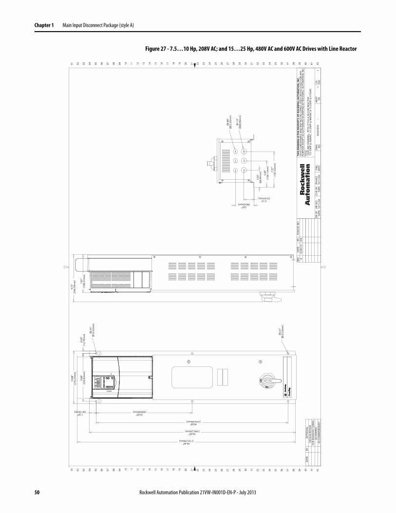
Chapter 1 Main Input Disconnect Package (style A)
Figure 27 - 7.5…10 Hp, 208V AC; and 15…25 Hp, 480V AC and 600V AC Drives with Line Reactor
01 02 03 04 05 06 07 08 09 10 11 12 13 14 15 16 17 18 19 20 21 22 23 24 25 26 27 28 29 30 31 32 33 34 35 36 37 38 39 40 41 42
02 03 04 05 06 07 08 09 10 11 12 13 14 15 16 17 18 19 20 21 22 23 24 25 26 27 28 29 30 31 32 33 34 35 36 37 38 39 40 41 4201
DAT
ERE
V.BY
ECN
/CR.
NO
.A
12/0
5/12
JCK
APP
ROVA
LD
ESIG
N R
EVIE
WFO
R M
AN
UFA
CTU
RIN
GA
S SH
IPPE
DA
S CO
MM
ISSI
ON
ED
BYD
ATE
SH.
NEX
TN
O.
SH.
-D
WG
.EN
G.
TITL
E
CHK.
BY
NO
.D
ATE
DAT
ED
R. B
YD
ATE
THIS
DRA
WIN
G IS
TH
E PR
OPE
RTY
OF
ROCK
WEL
L A
UTO
MAT
ION
, IN
C.O
R IT
S SU
BSID
IARI
ES A
ND
MAY
NO
T BE
CO
PIED
, USE
D O
R D
ISCL
OSE
D F
OR
AN
YPU
RPO
SE E
XCEP
T A
S AU
THO
RIZE
D IN
WRI
TIN
G B
Y RO
CKW
ELL
AUTO
MAT
ION
, IN
C. 11
OU
TLIN
E D
RAW
ING
- PF
70, S
TYLE
A, W
/LIN
E RE
ACTO
R7.
5-10
HP
@ 2
08VA
C, 1
5-25
HP
@ 4
60VA
C &
15-
25H
P @
575
VAC
95D
0107
5JR
F/AC
I10
/11/
04JF
H/A
CI10
/11/
04
10.8
8" [2
76.2
3mm
]
9.88
" [2
50.8
3mm
]0.
50"
[12.
70m
m]
1.50" [38.10mm]
20.00" [508.00mm]
40.00" [1016.00mm]
43.00" [1092.20mm]
45.49" [1155.39mm]
�0
.41
" [
�1
0.3
2m
m]
7.81
" [1
98.3
7mm
]
9.72
" [2
46.7
9mm
]
2.12" [53.97mm]
3.87" [98.42mm]
3.50
" [8
8.90
mm
]
5.44
" [1
38.1
1mm
]
7.37
" [1
87.3
2mm
]
�1
.13
" [�
28
.58
mm
]
�0
.88
" [�
22
.23
mm
]
�0
.41
" [
�1
0.3
2m
m]
O F F
ON
50 Rockwell Automation Publication 21VW-IN001D-EN-P - July 2013

Chapter 2
Three-contactor Full-feature Bypass with Disconnect Package (style B)
This chapter describes the features and operation for the 3-contactor full-feature bypass with disconnect package (style B).
Hardware Overview The 3-contactor full-feature bypass with disconnect package (style B) enables the motor to be manually transferred from drive output to the AC line, or from the AC line to the drive, while the motor is at zero (0) speed. The contactor bypass is electrically interlocked. A means for disconnecting input power via a door interlocked fuse disconnect switch is standard. In addition, this package is supplied with a bypass control interface that provides status indication and enables remote activation of the bypass circuit.
Main Disconnect Switch (DS1)
An Allen-Bradley Bulletin 194R fused disconnect switch with lockable rotary mounted operator handle is provided. The disconnect switch is designed to meet disconnect switch requirements for branch circuit protection. The door-mounted handle accepts up to three padlocks.
Topic Page
Hardware Overview 51
Electrical Installation 57
Customer Connections 61
Operating Modes 62
Parameter Defaults 64
Drawing Index 68
Schematic Drawings 71
Inter-connect Drawings 83
Layout Drawings 86
Outline Drawings 95
Rockwell Automation Publication 21VW-IN001D-EN-P - July 2013 51

Chapter 2 Three-contactor Full-feature Bypass with Disconnect Package (style B)
Main Fuses (FU1…FU3)
Input line branch circuit protection fuses must be used to protect the input power lines. If input fuses are not provided with your drive, recommended fuse values are shown in Table 8 on page 52. The input fuse ratings listed in Table 8 on page 52 are applicable for one drive per branch circuit. Do not apply other loads to the fused circuit.
The recommended fuse type for all PowerFlex 70 and 700 packages for fan and pump applications is UL Class J, 600V.
ATTENTION: Most codes require that upstream branch circuit protection be provided to protect input power wiring. Install the fuses recommended in Table 8 on page 52. Do not exceed the fuse ratings. Failure to observe this precaution could result in damage to, or destruction of, the equipment.
Table 8 - Fuse Recommendations
Drive Rating Fuse Rating
Input Voltage kW Hp Amps
208V AC, 3-phase
0.75 1.0 10
1.5 2.0 15
2.2 3.0 20
4.0 5.0 20
5.5 7.5 35
7.5 10 40
11 15 80
480V AC, 3-phase
0.75 1.0 6
1.5 2.0 10
2.2 3.0 10
4.0 5.0 15
5.5 7.5 20
7.5 10 20
11 15 35
15 20 35
18.5 25 60
22 30 70
30 40 80
37 50 100
45 60 150
55 75 175
75 100 200
90 125 250
110 150 350
52 Rockwell Automation Publication 21VW-IN001D-EN-P - July 2013

Three-contactor Full-feature Bypass with Disconnect Package (style B) Chapter 2
Contactors (DIC, DOC, and BC)
Allen-Bradley Bulletin 100 contactors are provided for all ratings. The contactors function as described here:
• Drive input contactor (DIC) opens and closes input to the drive.
• Drive output contactor (DOC) opens and closes the connection between the drive and the motor.
• Bypass contactor (BC) opens and closes the connection to line-start the motor.
Motor Overload Relay (OL)
The motor overload relay is set at the factory to 100% of the drive output current. In many cases, this setting matches the motor full load amps (FLA). However, before starting the drive, check the setting on the motor overload relay to be sure that it is set properly for your motor. The settings for the motor overload relay are described here:
• For motors with a service factor less than 1.15, set the motor overload relays to 0.9x motor FLA.
• For motors with a service factor equal to, or greater than 1.15, set the motor overload relay to the motor FLA.
600V AC, 3-phase
2.2 3.0 10
4.0 5.0 15
5.5 7.5 20
7.5 10 20
11 15 35
15 20 35
18.5 25 60
22 30 70
30 40 80
37 50 100
45 60 150
55 75 175
75 100 200
90 125 250
110 150 350
Table 8 - Fuse Recommendations (Continued)
Drive Rating Fuse Rating
Input Voltage kW Hp Amps
Rockwell Automation Publication 21VW-IN001D-EN-P - July 2013 53

Chapter 2 Three-contactor Full-feature Bypass with Disconnect Package (style B)
Figure 28 - Setting Motor Overload
Table 9 - Overload Ratings
Drive Rating Overload Rating
Input Voltage kW Hp Trip Class Adjustment Range (Amps)
208V AC, 3-phase
0.75 1.0 20 3.2…16
1.5 2.0 20 3.2…16
2.2 3.0 20 3.2…16
4.0 5.0 20 5.4…27
5.5 7.5 20 9…45
7.5 10 20 9…45
11 15 20 18…90
9596
9798
GNDTB2 TB1
Motor Overload Relay
Adjustment Dial
DOCBC
OL
DIC T
L3
DS1
FU2
FU1
FU3
L2L1
54 Rockwell Automation Publication 21VW-IN001D-EN-P - July 2013

Three-contactor Full-feature Bypass with Disconnect Package (style B) Chapter 2
Control Transformer (T1)
115V AC control power is obtained via a supplied control power transformer. The control transformer is fused on the primary.
480V AC, 3-phase
0.75 1.0 20 1.0…5.0
1.5 2.0 20 1.0…5.0
2.2 3.0 20 3.2…16
4.0 5.0 20 3.2…16
5.5 7.5 20 3.2…16
7.5 10 20 5.4…27
11 15 20 9…45
15 20 20 9…45
18.5 25 20 9…45
22 30 20 9…45
30 40 20 18…90
37 50 20 18…90
45 60 20 18…90
55 75 20 40…200
75 100 20 40…200
90 125 20 40…200
110 150 20 40…200
600V AC, 3-phase
2.2 3.0 20 3.2…16
4.0 5.0 20 3.2…16
5.5 7.5 20 3.2…16
7.5 10 20 5.4…27
11 15 20 9…45
15 20 20 9…45
18.5 25 20 9…45
22 30 20 9…45
30 40 20 18…90
37 50 20 18…90
45 60 20 18…90
55 75 20 40…200
75 100 20 40…200
90 125 20 40…200
110 150 20 40…200
Table 9 - Overload Ratings (Continued)
Drive Rating Overload Rating
Input Voltage kW Hp Trip Class Adjustment Range (Amps)
Rockwell Automation Publication 21VW-IN001D-EN-P - July 2013 55

Chapter 2 Three-contactor Full-feature Bypass with Disconnect Package (style B)
Bypass Control Interface (CP1)
The operator interface on the bypass option box shows the following status indicators:
• READY (green) – On when power is applied to the drive-bypass unit.
• INTERLOCK OPEN (amber) – On when the customer interlock or Aux Fault is de-energized.
• BYPASS RUN (green) – On when the bypass contactor (BC) is energized.
• BYPASS TRIP (red) – On when a bypass fault condition exists (for example, bypass motor overload has tripped).
• PURGE (amber) – On when the purge condition is active.
• DRIVE OUTPUT ENABLE (Green) – On when the drive output contactor (DOC) is energized.
In addition, the bypass control interface contains two selector switches. Selector switch 1 (SS1) determines the state of the DIC, DOC, and BC contactors. Selector switch 2 (SS2) determines the source of control logic.
Figure 29 - Bypass Control Interface
MOTOROFF
DRIVETEST
HAND AUTO DRIVE BYPASS
MOTOR
BYPASSRUN
BYPASSTRIPPURGE
DOC
DRIVEOUTPUTENABLE
DIC
INTERLOCKOPEN
BC
OL
FOR DRIVE STATUSSEE DRIVE DISPLAYDRIVE
READY
56 Rockwell Automation Publication 21VW-IN001D-EN-P - July 2013

Three-contactor Full-feature Bypass with Disconnect Package (style B) Chapter 2
Electrical Installation Input Power Wiring
Refer to the PowerFlex 70 Adjustable Frequency AC Drives User Manual, publication 20A-UM001, or the PowerFlex 700 Adjustable Frequency AC Drive User Manual, publication 20B-UM001, for additional detailed information about input power wiring recommendations and selection.
Follow these steps to connect AC input power to the drive package.
1. Select the proper wire size according to NEC and all applicable local codes and standards. You must make openings in the option cabinet of the desired conduit size, following NEC and all applicable local codes and standards. Power terminal block specifications are listed in Table 10 on page 57.
2. Connect the three-phase AC input power leads (three-wire VAC) to the appropriate terminals. Connect the AC input power leads to terminalsL1, L2, and L3 on the fused disconnect switch.
3. Tighten the AC input terminal power terminals to the proper torque according to drive type as shown in Table 10 on page 57.
Table 10 - AC Input Power Terminal Block Specifications
ATTENTION: Protect the contents of the options cabinet from metal chips and other debris while making the conduit openings. Failure to observe this precaution could result in damage to, or destruction of, the equipment.
ATTENTION: Do not route signal and control wiring with power wiring in the same conduit. This can cause interference with drive operation. Failure to observe this precaution could result in damage to, or destruction of, the equipment.
Voltage Rating
kW Hp Maximum Wire Size(1)
mm2 (AWG)
(1) Maximum/minimum sizes that the terminal block accepts - these are not recommendations. If national or local codes require sizes outside the range, lugs can be used.
Minimum Wire Sizemm2 (AWG)
Recommended TorqueN•m (lb•in)
208V AC
0.75…3.7 1…5 10.0 (8) 2.5 (14) 1.6 (14)
5.5…7.5 7.5…10 25 (4) 2.5 (14) 2.8 (25)
11 15 50 (1) 4.0 (12) 4.0 (35.4)
480V AC
0.75…7.5 1…10 10.0 (8) 2.5 (14) 1.6 (14)
11…18.5 15…25 25 (4) 2.5 (14) 2.8 (25)
22…37 30…50 50 (1) 4.0 (12) 4.0 (35.4)
45…75 60…100 150 (300 MCM) 16 (6) 22.5 (200)
90…110 125…150 2 x 185 (350 MCM) 2 x 16 (6) 45.0 (398)
600V AC
0.75…7.5 1…10 10.0 (8) 2.5 (14) 1.6 (14)
11…18.5 15…25 25 (4) 2.5 (14) 2.8 (25)
22…37 30…50 50 (1) 4.0 (12) 4.0 (35.4)
45…75 60…100 150 (300 MCM) 16 (6) 22.5 (200)
90…110 125…150 2 x 185 (350 MCM) 2 x 16 (6) 45.0 (398)
Rockwell Automation Publication 21VW-IN001D-EN-P - July 2013 57

Chapter 2 Three-contactor Full-feature Bypass with Disconnect Package (style B)
Output Power Wiring
Refer to the PowerFlex 70 AC Drives User Manual, publication 20A-UM001, or the PowerFlex 700 Adjustable Frequency AC Drive User Manual, publication 20B-UM001, for additional detailed information about output power wiring recommendations and selection.
Follow these steps to connect AC output power wiring from the drive to the motor.
1. Wire the three-phase AC output power motor leads by routing them according to the drive option type. You must make openings in the option cabinet of the desired conduit size, following NEC and all applicable local codes and standards. Output power terminal block specifications are listed in Table 11 on page 59.
Do not route more than three sets of motor leads through a single conduit. This minimizes cross-talk that could reduce the effectiveness of noise reduction methods. If more than three drive/motor connections per conduit are required, shielded cable must be used. If possible, each conduit must contain only one set of motor leads.
2. Connect the three-phase AC output power motor leads to terminalsT1, T2, and T3 on the output power terminal block (TB2) inside the option cabinet.
3. Tighten the three-phase AC output power terminals to the proper torque according to drive type as shown in Table 11 on page 59 on the following page.
ATTENTION: Unused wires in conduit must be grounded at both ends to avoid a possible shock hazard caused by induced voltages. Also, if a drive sharing a conduit is being serviced or installed, all drives using this conduit must be disabled to eliminate the possible shock hazard from cross-coupled motor leads. Failure to observe these precautions could result in bodily injury.
ATTENTION: Do not route signal and control wiring with power wiring in the same conduit. This can cause interference with drive operation. Failure to observe this precaution could result in damage to, or destruction of, the equipment.
58 Rockwell Automation Publication 21VW-IN001D-EN-P - July 2013

Three-contactor Full-feature Bypass with Disconnect Package (style B) Chapter 2
Table 11 - Output Power Terminal Block Specifications
Control and Signal Wiring
Refer to the PowerFlex 70 AC Drives User Manual, publication 20A-UM001, or the PowerFlex 700 Adjustable Frequency AC Drive User Manual, publication 20B-UM001, for additional detailed information about control and signal wiring.
The I/O terminal block on the drive, and the control terminal block (TB1 terminals 31…40) inside the option cabinet, provide terminals for interfacing customer-supplied control inputs and outputs. All analog and discrete control wiring is made at these terminals. Table 12 on page 59 matches the I/O terminal blocks with the drive horsepower and voltage ratings.
Table 12 - I/O Terminal Blocks
Typical customer control and signal wiring is shown on the inter-connect drawings, Figure 42 on page 83, Figure 43 on page 84 and Figure 44 on page 85.
Follow these steps to connect control and signal wiring to the drive package.
Voltage Rating
kW Hp Maximum Wire Size(1)
mm2 (AWG)
(1) Maximum/minimum sizes that the terminal block accepts - these are not recommendations. If national or local codes require sizes outside the range, lugs can be used.
Minimum Wire Sizemm2 (AWG)
Recommended TorqueN•m (lb•in)
208V AC0.75…5.5 1…7.5 10.0 (8) 0.34 (22) 1.4 (13)
7.5…11 10…15 25 (4) 2.5 (14) 2.2 (20)
480V AC
0.75…5.5 1…15 10.0 (8) 0.34 (22) 1.4 (13)
7.5…22 20…30 25 (4) 2.5 (14) 2.2 (20)
30…55 40…75 35 (2) 2.5 (14) 5.7 (51)
75 100 2 x 185 (350 MCM) 2 x 16 (6) 31 (275)
90…110 125…150 2 x 185 (350 MCM) 2 x 16 (6) 31 (275)
600V AC
2.2…5.5 3…15 10.0 (8) 0.34 (22) 1.4 (13)
7.5…22 20…30 25 (4) 2.5 (14) 2.2 (20)
30…55 40…75 35 (2) 2.5 (14) 5.7 (51)
75 100 2 x 185 (350 MCM) 2 x 16 (6) 31 (275)
90…110 125…150 2 x 185 (350 MCM) 2 x 16 (6) 31 (275)
I/O Terminal Blocks Drive Rating
Terminals 1…261…20 Hp at 208V AC1…50 Hp at 480V AC1…50 Hp at 600V AC
Terminals 1…3260…150 Hp at 480V AC60…50 Hp at 600V AC
Rockwell Automation Publication 21VW-IN001D-EN-P - July 2013 59

Chapter 2 Three-contactor Full-feature Bypass with Disconnect Package (style B)
1. Wire the control and signal leads by routing them according to the drive option type. You must make openings in the option cabinet of the desired conduit size, following NEC and all applicable local codes and standards. Control and signal terminal block specifications are listed in Table 13 on page 60.
Control and signal wires must be separated from power wires by at least 0.3 m (1 ft).
2. Connect the analog and relay output signal wiring to the I/O terminal block on the drive.
3. Connect the control wiring listed below to terminals 31…40 inside the option cabinet.– Interlock– Freeze/Fire Stats– Autostart– Bypass– Purge– Bypass Running
4. Tighten the control and signal terminals to the proper torque according to drive type as shown in Table 13 on page 60.
Table 13 - I/O Terminal Block Specifications
Voltage Rating
kW Hp Terminals Location Maximum Wire Size(1)
mm2 (AWG)Minimum Wire Sizemm2 (AWG)
Recommended TorqueN•m (lb•in)
208V AC 0.75…11 1…151…26 Drive 1.5 (16) 0.05 (30) 0.5 (4.4)
31…40 Option Cabinet 6.0 (10) 0.34 (22) 0.6 (5.0)
480V AC
0.75…37 1…501…26 Drive 1.5 (16) 0.05 (30) 0.5 (4.4)
31…40 Option Cabinet 6.0 (10) 0.34 (22) 0.6 (5.0)
45…110 60…1501…32 Drive 2.5 (14) 0.34 (22) 0.6 (5.2)
31…40 Option Cabinet 6.0 (10) 0.34 (22) 0.6 (5.0)
600V AC
0.75…137 1…501…26 Drive 1.5 (16) 0.05 (30) 0.5 (4.4)
31…40 Option Cabinet 6.0 (10) 0.34 (22) 0.6 (5.0)
45…110 60…1501…32 Drive 2.5 (14) 0.34 (22) 0.6 (5.2)
31…40 Option Cabinet 6.0 (10) 0.34 (22) 0.6 (5.0)
(1) Maximum/minimum sizes that the terminal block accepts - these are not recommendations. If national or local codes require sizes outside the range, lugs can be used.
60 Rockwell Automation Publication 21VW-IN001D-EN-P - July 2013

Three-contactor Full-feature Bypass with Disconnect Package (style B) Chapter 2
Customer Connections The 3-contactor full-feature bypass with disconnect package is set up to accommodate the following customer-supplied contacts. Contacts must be rated for 120V AC.
Interlock
The “Interlock” input functions as an enable input when operating in either Drive or Bypass Mode. Opening the “Interlock” input (T31 and T32) prevents the drive/motor from running. T31 and T32 are shipped with a jumper wire installed from the factory. If you want to use the “Interlock” input, remove the jumper wire, and wire appropriately for the customer contacts being used. If a valid “Autostart” or “Bypass” contact is present, the drive/motor immediately runs upon the closing of the “Interlock” input.
Freeze/Fire Stat
The “Freeze/Fire Stat” input functions as a system fault input when operating in either Drive or Bypass Mode. Opening the “Freeze/Fire Stat” input (T31 and T33) prevents the drive/motor from running. T31 and T33 are shipped with a jumper wire installed from the factory. If you want to use the “Freeze/Fire Stat” input, remove the jumper wire, and wire appropriately for the customer contacts being used. If the “Freeze/Fire Stat” input opens while operating in Drive Mode, the drive faults and requires a manual reset to restart once the input closes. If the “Freeze/Fire Stat” input opens while operating in Bypass Mode, the motor coasts to a stop and immediately runs when the input closes.
Autostart
The “Autostart” input is used to remotely start the drive when SS1 is in the DRIVE position and SS2 is in the AUTO position. A closed input to terminals 34 and 35 starts the drive.
Bypass
The “Bypass” input is used to remotely start the motor across the 3-phase AC line when SS1 is in the BYPASS position and SS2 is in the AUTO position. A closed input to terminals 34 and 36 starts the motor.
Rockwell Automation Publication 21VW-IN001D-EN-P - July 2013 61

Chapter 2 Three-contactor Full-feature Bypass with Disconnect Package (style B)
Purge
A “Purge” input can be wired to terminals 37 and 38. When this input is closed, the motor runs at the purge frequency, which is defined by Parameter A141 [Purge Frequency], assuming the following conditions exist:
• SS1 is either in the DRIVE or BYPASS position.• SS2 is either in the HAND or AUTO position if Jumper P1 on the Bypass
Control Panel (CP1) is in position A.• SS2 is in the HAND, MOTOR OFF or AUTO position if jumper P1 on
the bypass control panel (CP1) is in position B.• Interlock wired to terminals 31 and 32 is closed.• Freeze/Fire Stat wired to terminals 31 and 33 is closed.
Bypass Running
The “Bypass Running” contact is normally open. When the bypass contactor (BC) is closed, the “Bypass Running” contact is also closed.
Operating Modes Selector switch 1 (SS1) and selector switch 2 (SS2), on the bypass control panel (CP1), are used to determine the operating state of the 3-contactor full-feature bypass with disconnect package. SS1 is used to select one of these motor control methods:
• DRIVE = Drive keypad/terminal block controls the motor• DRIVE TEST = Drive is powered but is not controlling the motor• BYPASS = Motor runs across 3-phase line
Jumper P2 on the bypass control panel (CP1) enables the drive to be powered while running in bypass. This is accomplished by moving jumper P2 to position B-C and turning SS1 from BYPASS to DRIVE TEST. If jumper P2 is in position A-B, the drive cannot be powered while running in bypass. SS2 selects the source of the start, stop, and drive speed reference as defined in Table 14 on page 63.
ATTENTION: A Purge command takes precedence over a Stop command from the Comm Port/Network. Be sure that another stop method is available if stopping is necessary during a purge.
62 Rockwell Automation Publication 21VW-IN001D-EN-P - July 2013

Three-contactor Full-feature Bypass with Disconnect Package (style B) Chapter 2
Table 14 - Command and Reference Selection
SS1 Selection
SS2 Selection
Start Command Stop Command Drive Speed Reference
TB Keypad None TB Keypad None TB Keypad None
DRIVE
HAND x x x
MOTOR OFF x x x
AUTO x x x x
DRIVE TEST
HAND x x x
MOTOR OFF x x x
AUTO x x x x
BYPASS
HAND Automatically starts Automatically starts Motor runs at base speed
MOTOR OFF x x x
AUTO x x Motor runs at base speed
ATTENTION: Three-contactor full-feature bypass with disconnect packages are not designed to allow control over a communication network while in Auto Mode. The communication network is intended only for monitoring purposes. If network control is required, wiring and parameters changes are required.
Rockwell Automation Publication 21VW-IN001D-EN-P - July 2013 63

Chapter 2 Three-contactor Full-feature Bypass with Disconnect Package (style B)
Refer to the PowerFlex 70 AC Drives User Manual, publication 20A-UM001, or the PowerFlex 700 Adjustable Frequency AC Drive User Manual, publication 20B-UM001, for detailed information on parameters and programming.
Parameter DefaultsThree-contactor Full-feature Bypass with Disconnect Package (style B)
Parameter Name Number Default
Output Freq 001 Read Only
Commanded Freq 002 Read Only
Output Current 003 Read Only
Output Voltage 004 Read Only
Flux Current 005 Read Only
Output Voltage 006 Read Only
Output Power 007 Read Only
Output Powr Fctr 008 Read Only
Elapsed MWh 009 Read Only
Elapsed Run Time 010 Read Only
MOP Frequency 011 Read Only
DC Bus Voltage 012 Read Only
DC Bus Memory 013 Read Only
Elapsed kWh 014(1) Read Only
Analog In1 Value 016 Read Only
Analog In2 Value 017 Read Only
Ramped Speed 022(1) Read Only
Speed Reference 023(1) Read Only
Commanded Torque 024(1) Read Only
Speed Feedback 025(1) Read Only
Rated kW 026 Read Only
Rated Volts 027 Read Only
Rated Amps 028 Read Only
Control SW Ver 029 Read Only
Motor Type 040 Induction
Motor NP Volts 041 Drive Rating Based
Motor NP FLA 042 Drive Rating Based
Motor NP Hertz 043 Drive Rating Based
Motor NP PRM 044 Drive Rating Based
Motor NP Power 045 Drive Rating Based
Mtr NP Pwr Units 046 Drive Rating Based
Motor OL Hertz 047 Motor NP Hz/3
Motor OL Factor 048 1.00
Motor Poles 049(1) 4
Motor Cntl Sel 053(2) 3 “FAN/Pump V/Hz”
Maximum Voltage 054 Drive Rated Volts
64
Maximum Freq 055 110.0 or 130.0 Hz
Compensation 056Bits 0…60101111
Flux Up Mode 057 “Manual”
Flux Up Time 058 0.000 Secs
SV Boost Filter 059 500
Autotune 061 “Calculate”
IR Voltage Drop 062 Based on Drive Rating
Flux Current Ref 063 Based on Drive Rating
Ixo Voltage Drop 064 Based on Drive Rating
Autotune Torque 066(1) 50%
Inertia Autotune 067(1) “Ready”
St Acc Boost 069 Based on Drive Rating
Run Boost 070 Based on Drive Rating
Break Voltage 071 [Motor NP Volts] × 0.25
Break Frequency 072 [Motor NP Hz] × 0.25
Speed Units 079 0 “Hz”
Feedback Select] 080 0 “Open Loop”
Minimum Speed 081 0.0
Maximum Speed 08250.0 or 60.0 Hz (volt class)[Motor NP RPM]
Overspeed Limit 08310.0 Hz300.0 RPM
Skip Frequency 1 084 0.0 Hz
Skip Frequency 2 085 0.0 Hz
Skip Frequency 3 086 0.0 Hz
Skip Freq Band 087(2) 1.0 Hz
Speed/Torque Mod 088(1) 1 “Speed Reg”
Speed Ref A Sel 090(2) 1 “Analog In 1”
Speed Ref A Hi 091 Maximum Speed
Speed Ref A Lo 092 0.0
Speed Ref B Sel 093(2) 18 “DPI Port 1”
Speed Ref B Hi 094 Maximum Speed
Parameter Name Number Default
Rockwell Automation Publication 21VW-IN001D-EN-P - July 20
Speed Ref B Lo 095 0.0
TB Man Ref Sel 096 1 “Analog In 1”
TB Man Ref Hi 097 Maximum Speed
TB Man Ref Lo 098 0.0
Pulse Input Ref 099 Read Only
Jog Speed 1 100 10.0 Hz
Preset Speed 1 101 5.0 Hz
Preset Speed 2 102(2) 5.0 Hz
Preset Speed 3 103 20.0 Hz
Preset Speed 4 104 30.0 Hz
Preset Speed 5 105 40.0 Hz
Preset Speed 6 106 50.0 Hz
Preset Speed 7 107 6.0 Hz
Jog Speed 2 108 10.0 Hz
Trim % Setpoint 116(1) 0.0%
Trim In Select 117 2 “Analog In 2”
Trim Out Select 118 0 (Disable)
Trim Hi 119 60.0 Hz
Trim Lo 120 0.0 Hz
Slip RPM @ FLA 121 Based on [Motor NP RPM]
Slip Comp Gain 122 40.0
Slip RPM Meter 123 Read Only
PI Configuration 124 0 (Disable)
PI Control 125 0 (Disable)
PI Reference Sel 126 0 “PI Setpoint”
PI Setpoint 127 50.00%
PI Feedback Sel 128 0 “PI Setpoint”
PI Integral Time 129 2.00 Secs
PI Prop Gain 130 1.0
PI Lower Limit 131 –[Maximum Freq]–100%
PI Upper Limit 132 +[Maximum Freq] 100%
PI Preload 133 0.0 Hz100.0%
PI Status 134 Read Only
PI Ref Meter 135 Read Only
Parameter Name Number Default
13

Three-contactor Full-feature Bypass with Disconnect Package (style B) Chapter 2
PI Fdback Meter 136 Read Only
PI Error Meter 137 Read Only
PI Output Meter 138 Read Only
PI BW Filter 139(1) 0.0 Radians
Accel Time 1 140(2) 20.0 Secs
Accel Time 2 141(2) 20.0 Secs
Decel Time 1 142(2) 20.0 Secs
Decel Time 2 143(2) 20.0 Secs
DB While Stopped 145(1) 0 “Disabled”
S Curve % 146(2) 20%
Current Lmt Sel 147 0 “Cur Lim Val”
Current Lmt Val 148
[Rated Amps] × 1.5 (Equation yields approximate default value.)
Current Lmt Gain 149 250
Drive OL Mode 150 3 “Both–PWM 1st”
PWM Frequency 151
4 kHz2 kHz(Frames 4…6, 600/690VAC)
Droop RPM @ FLA 152(1) 0.0 RPM
Regen Power Limit 153(1) –50.0%
Current Rate Limit 154(1) 400.0%
Stop Mode A 155(2) 0 “Coast”
Stop Mode B 156(2) 1 “Ramp”
DC Brake Lvl Sel 157 0 “DC Brake Lvl”
DC Brake Level 158 [Rated Amps]
DC Brake Time 159 0.0 Secs
Bus Reg Ki 160 450
Bus Reg Mode A 161 1 “Adjust Freq”
Bus Reg Mode B 162(2) 0 “Disabled”
DB Resistor Type 163 0 “None”
Bus Reg Kp 164(2) 1200
Bus Reg Kd 165 1000
Flux Braking 166(1) 0 “Disabled”
Powerup Delay 167(1) 0.0 Secs
Start At PowerUp 168(2) 1 “Enabled”
Flying Start En 169(2) 1 “Enabled”
Flying StartGain 170 4000
Auto Rstrt Tries 174 0
Auto Rstrt Delay 175(2) 30.0 Secs
Gnd Warn Level 177(1) 3.0 Amps
Parameter Name Number Default
R
Sleep-Wake Mode 178 0 “Disabled”
Sleep-Wake Ref 179 2 “Analog In 2”
Wake Level 180 6.000 mA,6.000 Volts
Wake Time 181 1.0 Secs
Sleep Level 182 5.000 mA,5.000 Volts
Sleep Time 183 1.0 Secs
Power Loss Mode 184 0 “Coast”
Power Loss Time 185 0.5 Secs
Power Loss Level 186(3) Drive Rated Volts
Load Loss Level 187(1) 200.0%
Load Loss Time 188(1) 0.0 Secs
Shear Pin Time 189(1) 0.0 Secs
Direction Mode 190(2) 2 “Reverse Dis”
Save HIM Ref 192 0 Hz
Man Ref Preload 193(3) 0 “Disabled”
Save MOP Ref 194(2) At Pwr Down
MOP Rate 195 1.0 Hz/s30.0 RPM/s
Param Access Lvl 196(2) 3 “Fan/Pump”
Reset To Defalts 197 0 “Ready”
Load Frm Usr Set 198 0 “Ready”
Save To User Set 199 0 “Ready”
Reset Meters 200 0 “Ready”
Language 201 0 “Not Selected”
Voltage Class 202 Based on Drive Cat. No.
Drive Checksum 203 Read Only
Dyn UsrSet Cnfg 204(1) 0 “Disabled”
Dyn UsrSet Sel 205(1) 0 “Disabled”
Dyn UsrSet Actv 206(1) 0 “Disabled”
Drive Status 1 209 Read Only
Drive Status 2 210 Read Only
Drive Alarm 1 211 Read Only
Drive Alarm 2 212 Read Only
Speed Ref Source 213 Read Only
Start Inhibits 214 Read Only
Last Stop Source 215 Read Only
Dig In Status 216 Read Only
Dig Out Status 217 Read Only
Drive Temp 218 Read Only
Parameter Name Number Default
ockwell Automation Publication 21VW-IN001D-EN-P - July 2013
Drive OL Count 219 Read Only
Motor OL Count 220 Read Only
Fault Speed 224 Read Only
Fault Amps 225 Read Only
Fault Bus Volts 226 Read Only
Status 1 @ Fault 227 Read Only
Status 2@ Fault 228 Read Only
Alarm 1 @ Fault 229 Read Only
Alarm 2@ Fault 230 Read Only
Testpoint 1 Sel 234 499
Testpoint 2 Sel 236 499
Testpoint 1 Data 235 Read Only
Testpoint 2 Data 237 Read Only
Fault Config 1 238Bits 0…1501x1001000x000xx
Fault Clear 240 0 “Ready”
Fault Clear Mode 241 1 “Enabled”
Power Up Marker 242 Read Only
Fault 1 Code 243 Read Only
Fault 1 Time 244 Read Only
Fault 2 Code 245 Read Only
Fault 2 Time 246 Read Only
Fault 3 Code 247 Read Only
Fault 3 Time 248 Read Only
Fault 4 Code 249 Read Only
Fault 4 Time 250 Read Only
Fault 5 Code 251(3) Read Only
Fault 5 Time 252(3) Read Only
Fault 6 Code 253(3) Read Only
Fault 6Time 254(3) Read Only
Fault 7 Code 255(3) Read Only
Fault 7 Time 256(3) Read Only
Fault 8 Code 257(3) Read Only
Fault 8 Time 258(3) Read Only
Alarm Config 1 259Bits 0-15000000x00000000x
Alarm Clear 261(3) 0 “Ready”
Alarm 1 Code 262(3) Read Only
Alarm 2 Code 263(3) Read Only
Alarm 3 Code 264(3) Read Only
Alarm 4 Code 265(3) Read Only
Parameter Name Number Default
65

Chapter 2 Three-contactor Full-feature Bypass with Disconnect Package (style B)
Alarm 5 Code 266(3) Read Only
Alarm 6 Code 267(3) Read Only
Alarm 7 Code 268(3) Read Only
Alarm 8 Code 269(3) Read Only
DPI Baud Rate 270 1 “500kbps”
Drive Logic Rslt 271 Read Only
Drive Ref Rslt 272 Read Only
Drive Ramp Rslt 273 Read Only
DPI Port Sel 274(1) “DPI Port 1”
DPI Port Value 275(1) Read Only
Logic Mask 276(1) 1 - Control Permitted
Start Mask 277 (See Logic Mask)
Jog Mask 278 (See Logic Mask)
Direction Mask 279 (See Logic Mask)
Reference Mask 280 (See Logic Mask)
Accel Mask 281 (See Logic Mask)
Decel Mask 282 (See Logic Mask)
Fault Clr Mask 283 (See Logic Mask)
MOP Mask 284 (See Logic Mask)
Local Mask 285 (See Logic Mask)
Stop Owner 288 Read Only
Start Owner 289 (See Stop Owner)
Jog Owner 290 (See Stop Owner)
Direction Owner 291 (See Stop Owner)
Reference Owner 292 (See Stop Owner)
Accel Owner 293 (See Stop Owner)
Decel Owner 294 (See Stop Owner)
Fault Clr Owner 295 (See Stop Owner)
MOP Owner 296 (See Stop Owner)
Local Owner 297 (See Stop Owner)
DPI Ref Select 298(1) 0 “Max Freq”
DPI Fdbk Select 299 17 “Speed Fdbk”
Data In A1 - Link A Word 1 300 0(0 = “Disabled)
Data In A2 - Link A Word 2 301 0(0 = “Disabled)
Data In B1 - Link B Word 1 302 (See Data In A1 -
Link A Word 1)
Data In B2 - Link B Word 2 303 (See Data In A2 -
Link A Word 2)
Data In C1 - Link C Word 1 304 (See Data In A1 -
Link A Word 1)
Parameter Name Number Default
66
Data In C2 - Link C Word 2 305 (See Data In A2 -
Link A Word 2)
Data In D1 - Link D Word 1 306 (See Data In A1 -
Link A Word 1)
Data In D2 - Link D Word 2 307 (See Data In A2 -
Link A Word 2)
Data Out A1 - Link A Word 1 310 0(0 = “Disabled)
Data Out A2 - Link A Word 2 311 0(0 = “Disabled)
Data Out B1 - Link A Word 1 312 (See Data Out A1 -
Link A Word 1)
Data Out B2 - Link A Word 2 313 (See Data Out A2 -
Link A Word 2)
Data Out C1 - Link A Word 1 314 (See Data Out A1 -
Link A Word 1)
Data Out C2 - Link A Word 2 315 (See Data Out A2 -
Link A Word 2)
Data Out D1 - Link A Word 1 316 (See Data Out A1
Link A Word 1)
Data Out D2 - Link A Word 2 317 (See Data Out A2 -
Link A Word 2)
Anlg In Config 320(2) Analog In 1 = 0.0 Volt
Anlg In Sqr Root 321 0 (Disable)
Analog In 1 Hi 322 10.000 Volt
Analog In 1 Lo 323 0.000 Volt
Analog In 1 Loss 324 0 “Disabled”
Analog In 2 Hi 325 10.000 Volt
Analog In 2 Lo 326 0.000 Volt
Analog In 2 Loss 327 0 “Disabled”
Anlg Out Config 340 1 (Current)
Anlg Out Absolut 341 1 (Absolute)
Analog Out1 Sel 342 0 “Output Freq”
Analog Out1 Hi 343 20.000 mA,10.000 Volts
Analog Out1 Lo 344 0.000 mA,0.000 Volts
Analog Out2 Sel 345 0 “Output Freq”
Analog Out Hi 346 20.000 mA,10.000 Volts
Analog Out2 Lo 347 0.000 mA,0.000 Volts
Anlg Out1 Scale 354(1) 0.0
Anlg Out2 Scale 355(1) 0.0
Digital In1 Sel 361 4 “Stop – CF”
Digital In2 Sel 362 5 “Start”
Parameter Name Number Default
Rockwell Automation Publication 21VW-IN001D-EN-P - Jul
Digital In3 Sel 363(2) 3 “Aux Fault”
Digital In4 Sel 364(2) 1 “Enable”
Digital In5 Sel 365(2) 15 “Speed Sel 1”
Digital In6 Sel 366(2) 16 “Speed Sel 2”
Anlg1 Out Setpt 377(1) 20.000 mA,10.000 Volts
Anlg2 Out Setpt 378 20.000 mA,10.000 Volts
Dig Out Setpt 379(1) 0 (Disable)
Digital Out1 Sel 380(4) 1 “Fault”
Dig Out1 Level 381 0.0
Dig Out1 OnTime 382 0.00 Secs
Dig Out1 OffTime 383 0.00 Secs
Digital Out2 Sel 384 4 “Run”
Dig Out2 Level 385 0.0
Dig Out2 OnTime 386 0.00 Secs
Dig Out2 OffTime 387 0.00 Secs
Digital Out3 Sel 388 4 “Run”
Dig Out3 Level 389 0.0
Dig Out3 OnTime 390 0.00 Secs
Dig Out3 OffTime 391 0.00 Secs
Dig Out Param 393 0 “PI Config”
DigIn DataLogic 411(1) 0=Logical 0
Motor Fdbk Type 412(1) 0 “Quadrature”
Encoder PPR 413(1) 1024 PPR
Enc Position Fdbk 414(1) Read Only
Encoder Speed 415(1) Read Only
Fdbk Filter Sel 416(1) 0 “None”
Notch FilterFreq 419(1) 0.0 Hz
Notch Filter K 420(1) 0.3 Hz
Marker Pulse 421 Read Only
Pulse In Scale 422 64
Encoder Z Chan 423 0 “Pulse Input”
Torque Ref A Sel 427 1 “Torque Stpt1”
Torque Ref A Hi 428(1) 100.0%
Torque Ref A Lo 429(1) 0.0%
Torq Ref A Div 430(1) 1.0
Torque Ref B Sel 431 24 “Disabled”
Torque Ref B Hi 432 100.0%
Torque Ref B Lo 433 0.0%
Torque Ref B Mult 434 1.0
Parameter Name Number Default
y 2013

Three-contactor Full-feature Bypass with Disconnect Package (style B) Chapter 2
Torque Setpoint1 435(1) 0.0%
Pos Torque Limit 436(1) 200.0%
Neg Torque Limit 437(1) -200.0%
Torque Setpoint2 438 0.0%
Control Status 440(1) Read Only
Mtr Tor Cur Ref 441(1) Read Only
Ki Speed Loop 445(1) 7.0
Kp Speed Loop 446(1) 6.3
Kf Speed Loop 447(1) 0.0
Speed Desired BW 449(1) 0.0 Radians/Sec
Total Inertia 450(1) 1.25 Secs0.10 Secs (v3)
Speed Loop Meter 451(1) Read Only
Rev Speed Limit 454(1) 0.0 RPM
PI Deriv Time 459(1) 0.00 Secs
PI Reference Hi 460(1) 100.0%
PI Reference Lo 461(1) -100.0%
PI Feedback Hi 462(1) 100.0%
PI Feedback Lo 463(1) 0.0%
Scale1 In Value 476 0.0
Scale1 In Hi 477 0.0
Scale1 In Lo 478 0.0
Scale1 Out Hi 479 0.0
Scale1 Out Lo 480 0.0
Scale1 Out Value 481 Read Only
Scale2 In Value 482 0.0
Scale2 In Hi 483 0.0
Scale2 In Lo 484 0.0
Scale2 Out Hi 485 0.0
Parameter Name Number Default
Rock
ATTENTION: Parameter 168 [Start Aautomatically cause the drive to resuand/or personal injury can result if tconsidering applicable local, nationa
Scale2 Out Lo 486 0.0
Scale2 Out Value 487 Read Only
Scale3 In Value 488 0.0
Scale3 In Hi 489 0.0
Scale3 In Lo 490 0.0
Scale3 Out Hi 491 0.0
Scale3 Out Lo 492 0.0
Scale3 Out Value 493 Read Only
Scale4 In Value 494 0.0
Scale4 In Hi 495 0.0
Scale4 In Lo 496 0.0
Scale4 Out Hi 497 0.0
Scale4 Out Lo 498 0.0
Scale4 Out Value 499 Read Only
PortMask Act 595(1) Read Only
Write Mask Cfg 596(1) 1 = Write Permitted
Write Mask Act 597(1) Read Only
Logic Mask Act 598(1) Read Only
TorqProve Cnfg 600 0 (Disable)
TorqProve Setup 601 0 (Disable)
Spd Dev Band 6022.0 Hz60.0 RPM
SpdBand Integrat 603 60 mSec
Brk Release Time 604 0.10 Secs
ZeroSpdFloatTime 605 5.0 Secs
Float Tolerance 6060.2 Hz6.0 RPM
Brk Set Time 607 0.10 Secs
TorqLim SlewRate 608 10.0 Secs
Parameter Name Number Default
well Automation Publication 21VW-IN001D-EN-P - July 2013
t PowerUp] ships from the factory enabled. This feme running at commanded speed after drive inpu
his parameter is used in an inappropriate applicatil and international codes, standards, regulations,
BrkSlip Count 609 250
Brk Alarm Travel 610 1.0 Revs
MicroPos Scale% 611 10.0%
(1) Applicable only to PowerFlex 70 Packages.(2) The default values for these parameters differ from the
factory defaults. Setting 194 [Reset To Defalts] to 1 “Factory Rset” changes these parameter settings to the defaults listed in the PowerFlex 70 Adjustable Frequency AC Drives User Manual, publication 20A-UM001, or the PowerFlex 700 Adjustable Frequency AC Drive User Manual, publication 20B-UM001.
(3) Applicable only to PowerFlex 700 Packages.(4) When [TorqProve Cnfg] is set to “Enable,” [Digital Out1 Sel]
becomes the brake control and any other selection is ignored.
Parameter Name Number Default
67
ature enables a Run command to t power is restored. Equipment damage on. Do not use this function without or industry guidelines.

Chapter 2 Three-contactor Full-feature Bypass with Disconnect Package (style B)
Drawing Index Three-contactor Full-feature Bypass with Disconnect Package (style B)
The tables on the following pages provide links to the drawings for the various voltages and kW/Hp ratings for the style B packaged drives:
• Table 15, Three-contactor Full-feature Bypass with Disconnect Package (style B), 208V on page 68
• Table 16, Three-contactor Full-feature Bypass with Disconnect Package (style B), 480V on page 69
• Table 17, Three-contactor Full-feature Bypass with Disconnect Package (style B), 600V on page 70
Table 15 - Three-contactor Full-feature Bypass with Disconnect Package (style B), 208V
Input Voltage
kW Hp Input Line Reactor
Drawing
Outline Layout Schematic Inter-connect
208V AC
0.75 1.0
No
Figure 54 on page 95
Figure 45 on page 86Figure 30 on page 71 Figure 42 on page 83
1.5 2.0
2.2 3.0
4.0 5.0 Figure 55 on page 96
5.5 7.5Figure 56 on page 97
7.5 10
11 15 Figure 57 on page 98 Figure 46 on page 87
0.75 1.0
Yes
Figure 62 on page 103 Figure 51 on page 92
Figure 38 on page 79 Figure 44 on page 85
1.5 2.0
2.2 3.0
4.0 5.0 Figure 63 on page 104Figure 52 on page 93
5.5 7.5Figure 64 on page 105
7.5 10 Figure 53 on page 94
68 Rockwell Automation Publication 21VW-IN001D-EN-P - July 2013

Three-contactor Full-feature Bypass with Disconnect Package (style B) Chapter 2
Table 16 - Three-contactor Full-feature Bypass with Disconnect Package (style B), 480V
Input Voltage
kW Hp Input Line Reactor
Drawing
Outline Layout Schematic Inter-connect
480V AC
0.75 1.0
No
Figure 54 on page 95
Figure 45 on page 86
Figure 30 on page 71 Figure 42 on page 83
1.5 2.0
2.2 3.0
4.0 5.0
5.5 7.5Figure 55 on page 96
7.5 10
11 15
Figure 56 on page 9715 20
18.5 25
22 30 Figure 57 on page 98 Figure 46 on page 87
30 40Figure 58 on page 99 Figure 47 on page 88
37 50
45 60 Figure 59 on page 100 Figure 48 on page 89
Figure 32 on page 73 Figure 43 on page 84
55 75Figure 60 on page 101 Figure 49 on page 90
75 100
90 125Figure 61 on page 102 Figure 50 on page 91
110 150
0.75 1.0
Yes
Figure 62 on page 103 Figure 51 on page 92
Figure 38 on page 79 Figure 44 on page 85
1.5 2.0
2.2 3.0
4.0 5.0
5.5 7.5Figure 63 on page 104 Figure 52 on page 93
7.5 10
11 15
Figure 64 on page 105 Figure 53 on page 9415 20
18.5 25
Rockwell Automation Publication 21VW-IN001D-EN-P - July 2013 69

Chapter 2 Three-contactor Full-feature Bypass with Disconnect Package (style B)
Table 17 - Three-contactor Full-feature Bypass with Disconnect Package (style B), 600V
Input Voltage
kW Hp Input Line Reactor
Drawing
Outline Layout Schematic Inter-connect
600V AC
2.2 3.0
No
Figure 54 on page 95
Figure 45 on page 86
Figure 34 on page 75 Figure 42 on page 83
4.0 5.0
5.5 7.5Figure 55 on page 96
7.5 10
11 15
Figure 56 on page 9715 20
18.5 25
22 30 Figure 57 on page 98 Figure 46 on page 87
30 40Figure 58 on page 99 Figure 47 on page 88
37 50
45 60 Figure 59 on page 100 Figure 48 on page 89
Figure 36 on page 77 Figure 43 on page 84
55 75Figure 60 on page 101 Figure 49 on page 90
75 100
90 125Figure 61 on page 102 Figure 50 on page 91
110 150
2.2 3.0
Yes
Figure 62 on page 103 Figure 51 on page 92
Figure 39 on page 80 Figure 44 on page 85
4.0 5.0
5.5 7.5Figure 63 on page 104 Figure 52 on page 93
7.5 10
11 15
Figure 64 on page 105 Figure 53 on page 9415 20
18.5 25
70 Rockwell Automation Publication 21VW-IN001D-EN-P - July 2013

Three-contactor Full-feature Bypass with Disconnect Package (style B) Chapter 2
Schematic Drawings Figure 30 - 1…15 Hp, 208V AC; and 1…50 Hp, 480V AC Drives (sheet 1 of 2)
01 02 03 04 05 06 07 08 09 10 11 12 13 14 15 16 17 18 19 20 21 22 23 24 25 26 27 28 29 30 31 32 33 34 35 36 37 38 39 40 41 42
02 03 04 05 06 07 08 09 10 11 12 13 14 15 16 17 18 19 20 21 22 23 24 25 26 27 28 29 30 31 32 33 34 35 36 37 38 39 40 41 4201
SH
.N
EX
TN
O.
SH
.D
WG
.E
NG
.
TITL
E
CH
K. B
YN
O.
DAT
ED
ATE
DR
. BY
DAT
E
THIS
DR
AWIN
G IS
TH
E PR
OPE
RTY
OF
RO
CK
WEL
L A
UTO
MAT
ION
, IN
C.
OR
ITS
SU
BS
IDIA
RIE
S A
ND
MAY
NO
T B
E C
OP
IED
, US
ED
OR
DIS
CLO
SE
D F
OR
AN
YP
UR
PO
SE
EX
CE
PT
AS
AU
THO
RIZ
ED
IN W
RIT
ING
BY
RO
CK
WE
LL A
UTO
MAT
ION
, IN
C.
Rockwell Automation Publication 21VW-IN001D-EN-P - July 2013 71

Chapter 2 Three-contactor Full-feature Bypass with Disconnect Package (style B)
Figure 31 - 1…15 Hp, 208V AC; and 1…50 Hp, 480V AC Drives (sheet 2 of 2)
DAT
ER
EV.
BY
EC
N/C
R. N
O.
01 02 03 04 05 06 07 08 09 10 11 12 13 14 15 16 17 18 19 20 21 22 23 24 25 26 27 28 29 30 31 32 33 34 35 36 37 38 39 40 41 42
02 03 04 05 06 07 08 09 10 11 12 13 14 15 16 17 18 19 20 21 22 23 24 25 26 27 28 29 30 31 32 33 34 35 36 37 38 39 40 41 4201
SH
.N
EX
TN
O.
SH
.D
WG
.E
NG
.
TITL
E
CH
K. B
YN
O.
DAT
ED
ATE
DR
. BY
DAT
E
THIS
DR
AWIN
G IS
TH
E PR
OPE
RTY
OF
RO
CK
WEL
L A
UTO
MAT
ION
, IN
C.
OR
ITS
SU
BS
IDIA
RIE
S A
ND
MAY
NO
T B
E C
OP
IED
, US
ED
OR
DIS
CLO
SE
D F
OR
AN
YP
UR
PO
SE
EX
CE
PT
AS
AU
THO
RIZ
ED
IN W
RIT
ING
BY
RO
CK
WE
LL A
UTO
MAT
ION
, IN
C.
22
SC
HE
MAT
IC D
RAW
ING
- B
YPA
SS
CO
NTR
OL
PAN
EL
98D
0120
9JR
F/A
CI
1/19
/05
JFH
/AC
I1/
19/0
5
72 Rockwell Automation Publication 21VW-IN001D-EN-P - July 2013

Three-contactor Full-feature Bypass with Disconnect Package (style B) Chapter 2
Figure 32 - 60…150 Hp, 480V AC Drives (sheet 1 of 2)
01 02 03 04 05 06 07 08 09 10 11 12 13 14 15 16 17 18 19 20 21 22 23 24 25 26 27 28 29 30 31 32 33 34 35 36 37 38 39 40 41 42
02 03 04 05 06 07 08 09 10 11 12 13 14 15 16 17 18 19 20 21 22 23 24 25 26 27 28 29 30 31 32 33 34 35 36 37 38 39 40 41 4201
SH
.N
EX
TN
O.
SH
.D
WG
.E
NG
.
TITL
E
CH
K. B
YN
O.
DAT
ED
ATE
DR
. BY
DAT
E
THIS
DR
AWIN
G IS
TH
E PR
OPE
RTY
OF
RO
CK
WEL
L A
UTO
MAT
ION
, IN
C.
OR
ITS
SU
BS
IDIA
RIE
S A
ND
MAY
NO
T B
E C
OP
IED
, US
ED
OR
DIS
CLO
SE
D F
OR
AN
YP
UR
PO
SE
EX
CE
PT
AS
AU
THO
RIZ
ED
IN W
RIT
ING
BY
RO
CK
WE
LL A
UTO
MAT
ION
, IN
C.
Rockwell Automation Publication 21VW-IN001D-EN-P - July 2013 73

Chapter 2 Three-contactor Full-feature Bypass with Disconnect Package (style B)
Figure 33 - 60…150 Hp, 480V AC Drives (sheet 2 of 2)
DAT
ER
EV.
BY
EC
N/C
R. N
O.
01 02 03 04 05 06 07 08 09 10 11 12 13 14 15 16 17 18 19 20 21 22 23 24 25 26 27 28 29 30 31 32 33 34 35 36 37 38 39 40 41 42
02 03 04 05 06 07 08 09 10 11 12 13 14 15 16 17 18 19 20 21 22 23 24 25 26 27 28 29 30 31 32 33 34 35 36 37 38 39 40 41 4201
SH
.N
EX
TN
O.
SH
.D
WG
.E
NG
.
TITL
E
CH
K. B
YN
O.
DAT
ED
ATE
DR
. BY
DAT
E
THIS
DR
AWIN
G IS
TH
E PR
OPE
RTY
OF
RO
CK
WEL
L A
UTO
MAT
ION
, IN
C.
OR
ITS
SU
BS
IDIA
RIE
S A
ND
MAY
NO
T B
E C
OP
IED
, US
ED
OR
DIS
CLO
SE
D F
OR
AN
YP
UR
PO
SE
EX
CE
PT
AS
AU
THO
RIZ
ED
IN W
RIT
ING
BY
RO
CK
WE
LL A
UTO
MAT
ION
, IN
C.
22
SC
HE
MAT
IC D
RAW
ING
- B
YPA
SS
CO
NTR
OL
PAN
EL
98D
0121
0JR
F/A
CI
1/20
/05
JFH
/AC
I1/
20/0
5
74 Rockwell Automation Publication 21VW-IN001D-EN-P - July 2013

Three-contactor Full-feature Bypass with Disconnect Package (style B) Chapter 2
Figure 34 - 1…50 Hp, 600V AC Drives (sheet 1 of 2)
01 02 03 04 05 06 07 08 09 10 11 12 13 14 15 16 17 18 19 20 21 22 23 24 25 26 27 28 29 30 31 32 33 34 35 36 37 38 39 40 41 42
02 03 04 05 06 07 08 09 10 11 12 13 14 15 16 17 18 19 20 21 22 23 24 25 26 27 28 29 30 31 32 33 34 35 36 37 38 39 40 41 4201
SH
.N
EX
TN
O.
SH
.D
WG
.E
NG
.
TITL
E
CH
K. B
YN
O.
DAT
ED
ATE
DR
. BY
DAT
E
THIS
DR
AWIN
G IS
TH
E PR
OPE
RTY
OF
RO
CK
WEL
L A
UTO
MAT
ION
, IN
C.
OR
ITS
SU
BS
IDIA
RIE
S A
ND
MAY
NO
T B
E C
OP
IED
, US
ED
OR
DIS
CLO
SE
D F
OR
AN
YP
UR
PO
SE
EX
CE
PT
AS
AU
THO
RIZ
ED
IN W
RIT
ING
BY
RO
CK
WE
LL A
UTO
MAT
ION
, IN
C.
Rockwell Automation Publication 21VW-IN001D-EN-P - July 2013 75

Chapter 2 Three-contactor Full-feature Bypass with Disconnect Package (style B)
Figure 35 - 1…50 Hp, 600V AC Drives (sheet 2 of 2)
DAT
ER
EV.
BY
EC
N/C
R. N
O.
01 02 03 04 05 06 07 08 09 10 11 12 13 14 15 16 17 18 19 20 21 22 23 24 25 26 27 28 29 30 31 32 33 34 35 36 37 38 39 40 41 42
02 03 04 05 06 07 08 09 10 11 12 13 14 15 16 17 18 19 20 21 22 23 24 25 26 27 28 29 30 31 32 33 34 35 36 37 38 39 40 41 4201
SH
.N
EX
TN
O.
SH
.D
WG
.E
NG
.
TITL
E
CH
K. B
YN
O.
DAT
ED
ATE
DR
. BY
DAT
E
THIS
DR
AWIN
G IS
TH
E PR
OPE
RTY
OF
RO
CK
WEL
L A
UTO
MAT
ION
, IN
C.
OR
ITS
SU
BS
IDIA
RIE
S A
ND
MAY
NO
T B
E C
OP
IED
, US
ED
OR
DIS
CLO
SE
D F
OR
AN
YP
UR
PO
SE
EX
CE
PT
AS
AU
THO
RIZ
ED
IN W
RIT
ING
BY
RO
CK
WE
LL A
UTO
MAT
ION
, IN
C.
22
SC
HE
MAT
IC D
RAW
ING
- B
YPA
SS
CO
NTR
OL
PAN
EL
98D
0113
2JR
F/A
CI
12/1
0/04
JFH
/AC
I12
/10/
04
76 Rockwell Automation Publication 21VW-IN001D-EN-P - July 2013

Three-contactor Full-feature Bypass with Disconnect Package (style B) Chapter 2
Figure 36 - 60…150 Hp, 600V AC Drives (sheet 1 of 2)
01 02 03 04 05 06 07 08 09 10 11 12 13 14 15 16 17 18 19 20 21 22 23 24 25 26 27 28 29 30 31 32 33 34 35 36 37 38 39 40 41 42
02 03 04 05 06 07 08 09 10 11 12 13 14 15 16 17 18 19 20 21 22 23 24 25 26 27 28 29 30 31 32 33 34 35 36 37 38 39 40 41 4201
SH
.N
EX
TN
O.
SH
.D
WG
.E
NG
.
TITL
E
CH
K. B
YN
O.
DAT
ED
ATE
DR
. BY
DAT
E
THIS
DR
AWIN
G IS
TH
E PR
OPE
RTY
OF
RO
CK
WEL
L A
UTO
MAT
ION
, IN
C.
OR
ITS
SU
BS
IDIA
RIE
S A
ND
MAY
NO
T B
E C
OP
IED
, US
ED
OR
DIS
CLO
SE
D F
OR
AN
YP
UR
PO
SE
EX
CE
PT
AS
AU
THO
RIZ
ED
IN W
RIT
ING
BY
RO
CK
WE
LL A
UTO
MAT
ION
, IN
C.
Rockwell Automation Publication 21VW-IN001D-EN-P - July 2013 77

Chapter 2 Three-contactor Full-feature Bypass with Disconnect Package (style B)
Figure 37 - 60…150 Hp, 600V AC Drives (sheet 2 of 2)
DAT
ER
EV.
BY
EC
N/C
R. N
O.
01 02 03 04 05 06 07 08 09 10 11 12 13 14 15 16 17 18 19 20 21 22 23 24 25 26 27 28 29 30 31 32 33 34 35 36 37 38 39 40 41 42
02 03 04 05 06 07 08 09 10 11 12 13 14 15 16 17 18 19 20 21 22 23 24 25 26 27 28 29 30 31 32 33 34 35 36 37 38 39 40 41 4201
SH
.N
EX
TN
O.
SH
.D
WG
.E
NG
.
TITL
E
CH
K. B
YN
O.
DAT
ED
ATE
DR
. BY
DAT
E
THIS
DR
AWIN
G IS
TH
E PR
OPE
RTY
OF
RO
CK
WEL
L A
UTO
MAT
ION
, IN
C.
OR
ITS
SU
BS
IDIA
RIE
S A
ND
MAY
NO
T B
E C
OP
IED
, US
ED
OR
DIS
CLO
SE
D F
OR
AN
YP
UR
PO
SE
EX
CE
PT
AS
AU
THO
RIZ
ED
IN W
RIT
ING
BY
RO
CK
WE
LL A
UTO
MAT
ION
, IN
C.
22
SC
HE
MAT
IC D
RAW
ING
- B
YPA
SS
CO
NTR
OL
PAN
EL
98D
0113
3JR
F/A
CI
12/1
0/04
JFH
/AC
I12
/10/
04
78 Rockwell Automation Publication 21VW-IN001D-EN-P - July 2013

Three-contactor Full-feature Bypass with Disconnect Package (style B) Chapter 2
Figure 38 - 1…10 Hp, 208V AC; and 1…25 Hp, 480V AC Drives with Line Reactor (sheet 1 of 2)
01 02 03 04 05 06 07 08 09 10 11 12 13 14 15 16 17 18 19 20 21 22 23 24 25 26 27 28 29 30 31 32 33 34 35 36 37 38 39 40 41 42
02 03 04 05 06 07 08 09 10 11 12 13 14 15 16 17 18 19 20 21 22 23 24 25 26 27 28 29 30 31 32 33 34 35 36 37 38 39 40 41 4201
SH
.N
EX
TN
O.
SH
.D
WG
.E
NG
.
TITL
E
CH
K. B
YN
O.
DAT
ED
ATE
DR
. BY
DAT
E
THIS
DR
AWIN
G IS
TH
E PR
OPE
RTY
OF
RO
CK
WEL
L A
UTO
MAT
ION
, IN
C.
OR
ITS
SU
BS
IDIA
RIE
S A
ND
MAY
NO
T B
E C
OP
IED
, US
ED
OR
DIS
CLO
SE
D F
OR
AN
YP
UR
PO
SE
EX
CE
PT
AS
AU
THO
RIZ
ED
IN W
RIT
ING
BY
RO
CK
WE
LL A
UTO
MAT
ION
, IN
C.
Rockwell Automation Publication 21VW-IN001D-EN-P - July 2013 79

Chapter 2 Three-contactor Full-feature Bypass with Disconnect Package (style B)
Figure 39 - 1…10 Hp, 208V AC; and 1…25 Hp, 480V AC Drives with Line Reactor (sheet 2 of 2)
DAT
ER
EV.
BY
EC
N/C
R. N
O.
01 02 03 04 05 06 07 08 09 10 11 12 13 14 15 16 17 18 19 20 21 22 23 24 25 26 27 28 29 30 31 32 33 34 35 36 37 38 39 40 41 42
02 03 04 05 06 07 08 09 10 11 12 13 14 15 16 17 18 19 20 21 22 23 24 25 26 27 28 29 30 31 32 33 34 35 36 37 38 39 40 41 4201
SH
.N
EX
TN
O.
SH
.D
WG
.E
NG
.
TITL
E
CH
K. B
YN
O.
DAT
ED
ATE
DR
. BY
DAT
E
THIS
DR
AWIN
G IS
TH
E PR
OPE
RTY
OF
RO
CK
WEL
L A
UTO
MAT
ION
, IN
C.
OR
ITS
SU
BS
IDIA
RIE
S A
ND
MAY
NO
T B
E C
OP
IED
, US
ED
OR
DIS
CLO
SE
D F
OR
AN
YP
UR
PO
SE
EX
CE
PT
AS
AU
THO
RIZ
ED
IN W
RIT
ING
BY
RO
CK
WE
LL A
UTO
MAT
ION
, IN
C.
22
SC
HE
MAT
IC D
RAW
ING
- B
YPA
SS
CO
NTR
OL
PAN
EL
98D
0121
1JR
F/A
CI
1/19
/05
JFH
/AC
I1/
19/0
5
80 Rockwell Automation Publication 21VW-IN001D-EN-P - July 2013

Three-contactor Full-feature Bypass with Disconnect Package (style B) Chapter 2
Figure 40 - 3…25 Hp, 600V AC Drives with Line Reactor (sheet 1 of 2)
01 02 03 04 05 06 07 08 09 10 11 12 13 14 15 16 17 18 19 20 21 22 23 24 25 26 27 28 29 30 31 32 33 34 35 36 37 38 39 40 41 42
02 03 04 05 06 07 08 09 10 11 12 13 14 15 16 17 18 19 20 21 22 23 24 25 26 27 28 29 30 31 32 33 34 35 36 37 38 39 40 41 4201
SH
.N
EX
TN
O.
SH
.D
WG
.E
NG
.
TITL
E
CH
K. B
YN
O.
DAT
ED
ATE
DR
. BY
DAT
E
THIS
DR
AWIN
G IS
TH
E PR
OPE
RTY
OF
RO
CK
WEL
L A
UTO
MAT
ION
, IN
C.
OR
ITS
SU
BS
IDIA
RIE
S A
ND
MAY
NO
T B
E C
OP
IED
, US
ED
OR
DIS
CLO
SE
D F
OR
AN
YP
UR
PO
SE
EX
CE
PT
AS
AU
THO
RIZ
ED
IN W
RIT
ING
BY
RO
CK
WE
LL A
UTO
MAT
ION
, IN
C.
Rockwell Automation Publication 21VW-IN001D-EN-P - July 2013 81

Chapter 2 Three-contactor Full-feature Bypass with Disconnect Package (style B)
Figure 41 - 3…25 Hp, 600V AC Drives with Line Reactor (sheet 2 of 2)
DAT
ER
EV.
BY
EC
N/C
R. N
O.
01 02 03 04 05 06 07 08 09 10 11 12 13 14 15 16 17 18 19 20 21 22 23 24 25 26 27 28 29 30 31 32 33 34 35 36 37 38 39 40 41 42
02 03 04 05 06 07 08 09 10 11 12 13 14 15 16 17 18 19 20 21 22 23 24 25 26 27 28 29 30 31 32 33 34 35 36 37 38 39 40 41 4201
SH
.N
EX
TN
O.
SH
.D
WG
.E
NG
.
TITL
E
CH
K. B
YN
O.
DAT
ED
ATE
DR
. BY
DAT
E
THIS
DR
AWIN
G IS
TH
E PR
OPE
RTY
OF
RO
CK
WEL
L A
UTO
MAT
ION
, IN
C.
OR
ITS
SU
BS
IDIA
RIE
S A
ND
MAY
NO
T B
E C
OP
IED
, US
ED
OR
DIS
CLO
SE
D F
OR
AN
YP
UR
PO
SE
EX
CE
PT
AS
AU
THO
RIZ
ED
IN W
RIT
ING
BY
RO
CK
WE
LL A
UTO
MAT
ION
, IN
C.
22
SC
HE
MAT
IC D
RAW
ING
- B
YPA
SS
CO
NTR
OL
PAN
EL
98D
0121
2JR
F/A
CI
1/20
/05
JFH
/AC
I1/
20/0
5
82 Rockwell Automation Publication 21VW-IN001D-EN-P - July 2013

Three-contactor Full-feature Bypass with Disconnect Package (style B) Chapter 2
Inter-connect Drawings Figure 42 - 1…15 Hp, 208V AC; and 1…50 Hp, 480V AC and 600V AC Drives
DAT
ER
EV.
BY
EC
N/C
R. N
O.
01 02 03 04 05 06 07 08 09 10 11 12 13 14 15 16 17 18 19 20 21 22 23 24 25 26 27 28 29 30 31 32 33 34 35 36 37 38 39 40 41 42
02 03 04 05 06 07 08 09 10 11 12 13 14 15 16 17 18 19 20 21 22 23 24 25 26 27 28 29 30 31 32 33 34 35 36 37 38 39 40 41 4201
SH
.N
EX
TN
O.
SH
.D
WG
.E
NG
.
TITL
E
CH
K. B
YN
O.
DAT
ED
ATE
DR
. BY
DAT
E
THIS
DR
AWIN
G IS
TH
E PR
OPE
RTY
OF
RO
CK
WEL
L A
UTO
MAT
ION
, IN
C.
OR
ITS
SU
BS
IDIA
RIE
S A
ND
MAY
NO
T B
E C
OP
IED
, US
ED
OR
DIS
CLO
SE
D F
OR
AN
YP
UR
PO
SE
EX
CE
PT
AS
AU
THO
RIZ
ED
IN W
RIT
ING
BY
RO
CK
WE
LL A
UTO
MAT
ION
, IN
C.
A1/
28/0
5JR
F
11
INTE
R-C
ON
NE
CT
DR
AWIN
G -
PF7
0, S
TYLE
B1-
15H
P @
208
VAC
, 1-5
0HP
@ 4
60VA
C &
1-5
0HP
@ 5
75VA
C
97D
0116
6JR
F/A
CI
12/8
/04
JFH
/AC
I12
/8/0
4
12/8
/04
Rockwell Automation Publication 21VW-IN001D-EN-P - July 2013 83

Chapter 2 Three-contactor Full-feature Bypass with Disconnect Package (style B)
Figure 43 - 60…150 Hp, 480V AC and 600V AC Drives
84 Rockwell Automation Publication 21VW-IN001D-EN-P - July 2013

Three-contactor Full-feature Bypass with Disconnect Package (style B) Chapter 2
Figure 44 - 1…10 Hp, 208V AC; 1…25 Hp, 480V AC; and 3…25 Hp, 600V AC Drives with Line Reactor
DAT
ER
EV.
BY
EC
N/C
R. N
O.
01 02 03 04 05 06 07 08 09 10 11 12 13 14 15 16 17 18 19 20 21 22 23 24 25 26 27 28 29 30 31 32 33 34 35 36 37 38 39 40 41 42
02 03 04 05 06 07 08 09 10 11 12 13 14 15 16 17 18 19 20 21 22 23 24 25 26 27 28 29 30 31 32 33 34 35 36 37 38 39 40 41 4201
SH
.N
EX
TN
O.
SH
.D
WG
.E
NG
.
TITL
E
CH
K. B
YN
O.
DAT
ED
ATE
DR
. BY
DAT
E
THIS
DR
AWIN
G IS
TH
E PR
OPE
RTY
OF
RO
CK
WEL
L A
UTO
MAT
ION
, IN
C.
OR
ITS
SU
BS
IDIA
RIE
S A
ND
MAY
NO
T B
E C
OP
IED
, US
ED
OR
DIS
CLO
SE
D F
OR
AN
YP
UR
PO
SE
EX
CE
PT
AS
AU
THO
RIZ
ED
IN W
RIT
ING
BY
RO
CK
WE
LL A
UTO
MAT
ION
, IN
C.
A1/
28/0
5JR
FB
2/1/
05JR
F
11
INTE
R-C
ON
NE
CT
DR
AWIN
G -
PF7
0, S
TYLE
B, W
/ LIN
E R
EA
CTO
R1-
10H
P @
208
VAC
, 1-2
5HP
@ 4
60VA
C &
3-2
5HP
@ 5
75VA
C
97D
0074
9JR
F/A
CI
5/10
/04
JFH
/AC
I5/
10/0
4
Rockwell Automation Publication 21VW-IN001D-EN-P - July 2013 85

Chapter 2 Three-contactor Full-feature Bypass with Disconnect Package (style B)
Layout Drawings Figure 45 - 1…10 Hp, 208V AC; 1…25 Hp, 480V AC; and 3…25 Hp, 600V AC Drives
01 02 03 04 05 06 07 08 09 10 11 12 13 14 15 16 17 18 19 20 21 22 23 24 25 26 27 28 29 30 31 32 33 34 35 36 37 38 39 40 41 42
02 03 04 05 06 07 08 09 10 11 12 13 14 15 16 17 18 19 20 21 22 23 24 25 26 27 28 29 30 31 32 33 34 35 36 37 38 39 40 41 4201
DAT
ERE
V.BY
ECN
/CR.
NO
.A
1/24
/05
JRF
B5/
1/07
REH
C11
/1/0
7AW
RD
11/5
/12
JCK
APP
ROVA
LD
ESIG
N R
EVIE
WFO
R M
AN
UFA
CTU
RIN
GA
S SH
IPPE
DA
S CO
MM
ISSI
ON
ED
BYD
ATE
SH.
NEX
TN
O.
SH.
-D
WG
.EN
G.
TITL
E
CHK.
BY
NO
.D
ATE
DAT
ED
R. B
YD
ATE
THIS
DRA
WIN
G IS
TH
E PR
OPE
RTY
OF
ROCK
WEL
L A
UTO
MAT
ION
, IN
C.O
R IT
S SU
BSID
IARI
ES A
ND
MAY
NO
T BE
CO
PIED
, USE
D O
R D
ISCL
OSE
D F
OR
AN
YPU
RPO
SE E
XCEP
T A
S AU
THO
RIZE
D IN
WRI
TIN
G B
Y RO
CKW
ELL
AUTO
MAT
ION
, IN
C.
11
CON
TRO
L CO
MPO
NEN
T A
ND
TER
MIN
AL
BLO
CK L
OCA
TIO
NS
PF70
, STY
LE B
, 1-1
0HP
@ 2
08VA
C, 1
-25H
P @
460
VAC
& 3
-25H
P @
575
VAC
95D
0114
3JR
F/A
CI12
/8/0
4JF
H/A
CI12
/8/0
4
INPU
T PO
WER
TERM
INA
L BL
OCK
PE G
ROU
ND
FU4FU5
F1
SECONDARY
H2
PRIMARY
LISTE
D
IND
UST
RIA
L CO
NTR
OL
EQU
IPM
ENT
38M
N
U LC
178358-02
US
GND
T1T2T3
H1
X2
NO
NC2 1
4 3NO
3NO
4
8 7NOEM
AC
BE
D
BA
C
P1P2
BA
3
3NO
4
4
F
H3H4
CONN
2
CONN
1
F2X1
BCDIC
DO
C
T1
L2
DS1
TB1
TB2O
L
TERM
INA
L BL
OCK
OU
TPU
T PO
WER
CON
TRO
LTE
RMIN
AL
BLO
CK
40393837363534333231MGT3
T1T2
POW
ERTE
RMIN
AL
BLO
CK
TERM
INA
L BL
OCK
SIG
NA
L
CP1
TR
-3 -4
NO
-4 -3NO
-1NC
-2
-2
NC-1
-3 -4
NO
-4 -3NO
-1NC
-2
-2
NC-1
-3-4
NO
-4-3NO
-1NC
-2
-2
NC-1
AC_NOTE
-3-4
NO
-4-3NO
-1NC
-2
-2
NC-1
T1 T1 14 NO4 6T2 T314 NO 24 T2 6 T34 NO 2T2 6 T3 142 T1
L1 13 NO53 L2 L31L1 NO3 135 L3L213 NOL2 5 L3 131 L1
16 18 A2
15A1
L3L1
FU1
FU2
FU3
25H
P, 4
60VA
C VE
RSIO
N S
HO
WN
(3 D
IFFE
REN
T FR
AM
E SI
ZES
TOTA
L)
86 Rockwell Automation Publication 21VW-IN001D-EN-P - July 2013

Three-contactor Full-feature Bypass with Disconnect Package (style B) Chapter 2
Figure 46 - 30 Hp, 480V AC and 600V AC Drives
01 02 03 04 05 06 07 08 09 10 11 12 13 14 15 16 17 18 19 20 21 22 23 24 25 26 27 28 29 30 31 32 33 34 35 36 37 38 39 40 41 42
02 03 04 05 06 07 08 09 10 11 12 13 14 15 16 17 18 19 20 21 22 23 24 25 26 27 28 29 30 31 32 33 34 35 36 37 38 39 40 41 4201
DAT
ERE
V.BY
ECN
/CR.
NO
.A
1/24
/05
JRF
B4/
12/0
7RE
HC
5/1/
07RE
HD
11/1
/07
AWR
E7/
8/08
TGM
F11
/6/1
2JC
K
APP
ROVA
LD
ESIG
N R
EVIE
WFO
R M
AN
UFA
CTU
RIN
GA
S SH
IPPE
DA
S CO
MM
ISSI
ON
ED
BYD
ATE
SH.
NEX
TN
O.
SH.
-D
WG
.EN
G.
TITL
E
CHK.
BY
NO
.D
ATE
DAT
ED
R. B
YD
ATE
THIS
DRA
WIN
G IS
TH
E PR
OPE
RTY
OF
ROCK
WEL
L A
UTO
MAT
ION
, IN
C.O
R IT
S SU
BSID
IARI
ES A
ND
MAY
NO
T BE
CO
PIED
, USE
D O
R D
ISCL
OSE
D F
OR
AN
YPU
RPO
SE E
XCEP
T A
S AU
THO
RIZE
D IN
WRI
TIN
G B
Y RO
CKW
ELL
AUTO
MAT
ION
, IN
C.
11
CON
TRO
L CO
MPO
NEN
T A
ND
TER
MIN
AL
BLO
CK L
OCA
TIO
NS
PF70
, STY
LE B
, 30H
P @
460
VAC
& 3
0HP
@ 5
75VA
C
95D
0114
4JR
F/A
CI12
/8/0
4JF
H/A
CI12
/8/0
4
INPU
T PO
WER
TERM
INA
L BL
OCK
PE G
ROU
ND
T1
T3
T2
MG
31323334353637383940
TERM
INA
L BL
OCK
CON
TRO
LO
UTP
UT
POW
ERTE
RMIN
AL
BLO
CK
POW
ERTE
RMIN
AL
BLO
CK
SIG
NA
LTE
RMIN
AL
BLO
CK
Rock
well A
utom
ation
, Euc
lid, O
H 44
117 U
.S.A.
Suita
ble fo
r i nsta
llatio
n in a
Comp
artme
nt H
andli
ng Co
nditio
ned A
ir
ENCL
OSUR
E TYP
E: TY
PE 1
I/M __
____
_OU
TPUT
FREQ
UENC
Y:M
AX A
C OU
TPUT
:IN
PUT F
REQU
ENCY
:M
AX A
C IN
PUT:
M/N
____
__PO
WER
FLEXRe
lia
nc
e E
lec
tric
NO IND
UST
RIA
L CO
NTR
OL
EQU
IPM
ENT
38M
N
6102
93-2
41A
4
2
NO3
1NC
3NO
4
8 7NOEM
T3T1
T2M
G
SO: _
____
CL
USLIS
TED
U
178358-02
0-46
0V __
_A 3P
H
460V
___A
3PH
3-60
Hz
50/6
0Hz
__HP
L2
3 4
3 4
NO
PRIMARY
H3 H1H2H4
3632
3134
3533
4039
3837
FU4
FU5TA-2-69301
T
100VA
F2 X2F1X1
SECONDARY
BCA
CB
ED
P2A
CB
A B
P1
F
CONN
2
CONN
1
DIC
DO
C
TRCP
1
OL
T1TB
1TB
2
DS1
3 L1 15L3 L2
4 T1 26T3 T2NC-1 -2
-3NO
-4
NO-4
-2 -1NC
-3 -3
-1NC
-2
-4-3NO
-4
NO
-2
NC-1
-3
-1NC
-2
-4-3NO
-4
NO
-2
NC-1
A1A2A1A2
T3
L3
T3
L3
100-
C43D
00
1L15 L2 3
2T16 T2 4
L1 15 L2 3
T1 26 T2 4
5361
NC
5462
NC
NONO
-3 -4
NO
-4 -3NO
-3NO
-4
-4
NO-3
NC-1-2
-3NO
-4
NO -4
-2-1NC
-3
100-
SA11
100-
SA11
100-
SA11
100-
SA11
100-
SA20
100-
FA11
100-C37D00
100-
C37D
00
1618A2
FEA3T
15 A1
FU2
FU1
FU3
L1L3
Rockwell Automation Publication 21VW-IN001D-EN-P - July 2013 87

Chapter 2 Three-contactor Full-feature Bypass with Disconnect Package (style B)
Figure 47 - 15 Hp, 208V AC; 40…50 Hp, 480V AC and 600V AC Drives
01 02 03 04 05 06 07 08 09 10 11 12 13 14 15 16 17 18 19 20 21 22 23 24 25 26 27 28 29 30 31 32 33 34 35 36 37 38 39 40 41 42
02 03 04 05 06 07 08 09 10 11 12 13 14 15 16 17 18 19 20 21 22 23 24 25 26 27 28 29 30 31 32 33 34 35 36 37 38 39 40 41 4201
DAT
ERE
V.BY
ECN
/CR.
NO
.A
1/24
/05
JRF
B5/
1/07
REH
C11
/1/0
7AW
RD
7/9/
08TG
ME
11/6
/12
JCK
APP
ROVA
LD
ESIG
N R
EVIE
WFO
R M
AN
UFA
CTU
RIN
GA
S SH
IPPE
DA
S CO
MM
ISSI
ON
ED
BYD
ATE
SH.
NEX
TN
O.
SH.
-D
WG
.EN
G.
TITL
E
CHK.
BY
NO
.D
ATE
DAT
ED
R. B
YD
ATE
THIS
DRA
WIN
G IS
TH
E PR
OPE
RTY
OF
ROCK
WEL
L A
UTO
MAT
ION
, IN
C.O
R IT
S SU
BSID
IARI
ES A
ND
MAY
NO
T BE
CO
PIED
, USE
D O
R D
ISCL
OSE
D F
OR
AN
YPU
RPO
SE E
XCEP
T A
S AU
THO
RIZE
D IN
WRI
TIN
G B
Y RO
CKW
ELL
AUTO
MAT
ION
, IN
C.
11
CON
TRO
L CO
MPO
NEN
T A
ND
TER
MIN
AL
BLO
CK L
OCA
TIO
NS
PF70
, STY
LE B
, 15H
P @
208
VAC,
40-
50H
P @
460
VAC
&40
-50H
P @
575
VAC
95D
0114
5JR
F/A
CI12
/8/0
4JF
H/A
CI12
/8/0
4
INPU
T PO
WER
TERM
INA
L BL
OCK
PE G
ROU
ND
T1
T3
T2
31323334353637383940
TERM
INA
L BL
OCK
CON
TRO
LO
UTP
UT
POW
ERTE
RMIN
AL
BLO
CK
DO
CBC
DIC
T1
3736
3231
3334
3539
3840
AU-2
/0
GN
DL3
OL
DS1
TB2
TB1
U
IND
UST
RIA
L CO
NTR
OL
EQU
IPM
ENT
38M
N
USL
CLIS
TED
178358-02
2
4
1
3NO
NC
3 4NO
3 4
3 4
NOEM
NO
NO
8 7
AC
BF
ED
CONN
2
P1
BAC
AB
P2
CONN
1
POW
ERTE
RMIN
AL
BLO
CK
TERM
INA
L BL
OCK
SIG
NA
L
CP1
TR70
2T1
4T2
6T3
1L1
3L2
5L3
-3
-4
NO
-4
-3 NO
-1 NC
-2
-2
NC
-1
-3
-4
NO
-4
-3NO
-1NC
-2
-2
NC
-1
2T1
4T2
6T3
1L1
3L2
5L3
SECO
NDAR
Y
T
F1X2
X1F2
FU5
TA-2
-693
01
FU4
PRIM
ARY
H2H1
H4H3
5361
NC
5462
NC
NONO
-3
-4
NO
-4
-3NO
-3NO
-4
-4
NO
-3
1618
A2
FEA3
T
15A1
2T1
4T2
6T3
1L1
3L2
5L3
MG
FU2
FU1
FU3
L2L1
88 Rockwell Automation Publication 21VW-IN001D-EN-P - July 2013

Three-contactor Full-feature Bypass with Disconnect Package (style B) Chapter 2
Figure 48 - 60 Hp, 480V AC and 600V AC Drives
01 02 03 04 05 06 07 08 09 10 11 12 13 14 15 16 17 18 19 20 21 22 23 24 25 26 27 28 29 30 31 32 33 34 35 36 37 38 39 40 41 42
02 03 04 05 06 07 08 09 10 11 12 13 14 15 16 17 18 19 20 21 22 23 24 25 26 27 28 29 30 31 32 33 34 35 36 37 38 39 40 41 4201
DAT
ERE
V.BY
ECN
/CR.
NO
.A
1/24
/05
JRF
B4/
10/0
6RE
HC
5/1/
07RE
HD
11/1
/07
AWR
E12
/6/1
2JC
K
APP
ROVA
LD
ESIG
N R
EVIE
WFO
R M
AN
UFA
CTU
RIN
GA
S SH
IPPE
DA
S CO
MM
ISSI
ON
ED
BYD
ATE
SH.
NEX
TN
O.
SH.
-D
WG
.EN
G.
TITL
E
CHK.
BY
NO
.D
ATE
DAT
ED
R. B
YD
ATE
THIS
DRA
WIN
G IS
TH
E PR
OPE
RTY
OF
ROCK
WEL
L A
UTO
MAT
ION
, IN
C.O
R IT
S SU
BSID
IARI
ES A
ND
MAY
NO
T BE
CO
PIED
, USE
D O
R D
ISCL
OSE
D F
OR
AN
YPU
RPO
SE E
XCEP
T A
S AU
THO
RIZE
D IN
WRI
TIN
G B
Y RO
CKW
ELL
AUTO
MAT
ION
, IN
C.
11
CON
TRO
L CO
MPO
NEN
T A
ND
TER
MIN
AL
BLO
CK L
OCA
TIO
NS
PF70
0, S
TYLE
B, 6
0HP
@ 4
60VA
C &
60H
P @
575
VAC
95D
0122
2JR
F/A
CI1/
24/0
5JF
H/A
CI1/
24/0
5
6102
93-24
1A
NAME
PLAT
E
LISTE
D
IND
UST
RIA
L CO
NTR
OL
EQU
IPM
ENT
38M
N
C
178358-02
U LUS
T1
MG
T2
31323334353637383940
TERM
INA
L BL
OCK
CON
TRO
L
OU
TPU
T PO
WER
TERM
INA
L BL
OCK
38
T1T2T3
34
313233
353637
3940
TB1
TB2
T1
INPU
T PO
WER
TERM
INA
L BL
OCK
PE G
ROU
ND
SIG
NA
LTE
RMIN
AL
BLO
CK
TERM
INA
L BL
OCK
POW
ER
12
NO34
NO
NC
43
BC
A
43NO
NO
NOEM7
4
8
3
DE
F
BA
P2C
A B
P1
CONN
2
CONN
1
CP1
L1L2
L3D
S1
DO
CBC
DIC
TR
OL
T14
T26
1L1
3L2
5
-3
-4
NO
-4
-3 NO
-1 NC
-2
-2
NC
-1
-3
-4
NO
-4
-3 NO
-1 NC
-2
-2
NC
-1
2T1
4T2
6T3
1L1
3L2
5L3
-3
-4
NO
-4
-3NO
-1NC
-2
-2
NC
-1
5361
NC
5462
NC
NONO
1618
A2
FEA3
T
15A1
2T1
4T2
6T3
1L1
3L2
5L3
-3
-4
NO
-4
-3NO
-3NO
-4
-4
NO
-3
-3
-4
NO
-4
-3 NO
-1 NC
-2
-2
NC
-1
T3
MG
FU3
FU2
FU1
Rockwell Automation Publication 21VW-IN001D-EN-P - July 2013 89

Chapter 2 Three-contactor Full-feature Bypass with Disconnect Package (style B)
Figure 49 - 75…100 Hp, 480V AC and 600V AC Drives
01 02 03 04 05 06 07 08 09 10 11 12 13 14 15 16 17 18 19 20 21 22 23 24 25 26 27 28 29 30 31 32 33 34 35 36 37 38 39 40 41 42
02 03 04 05 06 07 08 09 10 11 12 13 14 15 16 17 18 19 20 21 22 23 24 25 26 27 28 29 30 31 32 33 34 35 36 37 38 39 40 41 4201
DAT
ERE
V.BY
ECN
/CR.
NO
.A
11/1
/07
AWR
B11
/6/1
2JC
KC
02/0
6/13
JCK
APP
ROVA
LD
ESIG
N R
EVIE
WFO
R M
AN
UFA
CTU
RIN
GA
S SH
IPPE
DA
S CO
MM
ISSI
ON
ED
BYD
ATE
SH.
NEX
TN
O.
SH.
-D
WG
.EN
G.
TITL
E
CHK.
BY
NO
.D
ATE
DAT
ED
R. B
YD
ATE
THIS
DRA
WIN
G IS
TH
E PR
OPE
RTY
OF
ROCK
WEL
L A
UTO
MAT
ION
, IN
C.O
R IT
S SU
BSID
IARI
ES A
ND
MAY
NO
T BE
CO
PIED
, USE
D O
R D
ISCL
OSE
D F
OR
AN
YPU
RPO
SE E
XCEP
T A
S AU
THO
RIZE
D IN
WRI
TIN
G B
Y RO
CKW
ELL
AUTO
MAT
ION
, IN
C.
11
CON
TRO
L CO
MPO
NEN
T A
ND
TER
MIN
AL
BLO
CK L
OCA
TIO
NS
PF70
0, S
TYLE
B, 7
5-10
0HP
@ 4
60VA
C &
75-
100H
P @
575
VAC
95D
0122
3JR
F/A
CI1/
24/0
5JF
H/A
CI1/
24/0
5
T1
MG
T2
31323334353637383940
TERM
INA
L BL
OCK
CON
TRO
LO
UTP
UT
POW
ERTE
RMIN
AL
BLO
CK
INPU
T PO
WER
TERM
INA
L BL
OCK
PE G
ROU
ND
SIG
NA
LTE
RMIN
AL
BLO
CK
TERM
INA
L BL
OCK
POW
ER
SECO
NDAR
YF1
X2X1
F2
FU5
TA-2
-693
02
FU4
PRIM
ARY
H2H1
H4H3
GN
D
AU-2
50
2
4
1
3NO
NC
3 4NO
3 4
3 4
NOEM
NO
NO
8 7
AC
BF
ED
CONN
2
P1
BAC
AB
P2
CONN
1
IND
UST
RIA
L CO
NTR
OL
EQU
IPM
ENT
38M
N
USLU
CLIS
TED
178358-02
-3
-4
NO
-4
-3NO
-1NC
-2
-2
NC
-1
2 13/16 [71.63]
33/64 [12.95]
[10mm
]
SCALE:
1 Inch
-3
-4
NO
-4
-3 NO
-1 NC
-2
-2
NC
-1
2 13/16 [71.63]
33/6
4 [1
2.95
]
[10m
m]
SCA
LE:
1 In
ch
5361
NC
5462
NC
NONO
1 29/32 [48.26]63/6
4 [2
4.89
]
[10m
m]
SCA
LE:
1 In
ch
BCD
OC
DIC
T1
3531
3233
3439
3840
3637
NAME
PLATE
6102
93-24
1A
1618
A2
FEA3
T
15A1
2T1
4T2
6T3
A1
1L1
3L2
5L3
A2
DS1
TB2
TB1
CP1
L1L2
L3
TR
T3
FU3
FU2
FU1
1 L1
3 L2
5 L3
2 T1
4 T2
6 T3
14
43NO
22
31NC32
NC21
44
NO131
L13
L25
L3
2 T1
4 T2
6 T3
14
43NO
22
31NC32
NC21
44
NO13 14
43NO
22
31NC32
NC21
44
NO13
14
43 NO
22
31 NC 32
NC 21
44
NO 13
14
43 NO
22
31 NC 32
NC 21
44
NO 13
OL
OU
TPU
T PO
WER
TERM
INA
L BL
OCK
T2T1
T3
MG
31323334353637383940
(75H
P M
OD
ELS)
(100
HP
MO
DEL
S)
TERM
INA
L BL
OCK
CON
TRO
L
DO
C
1 L1
3 L2
5 L3
2 T1
4 T2
6 T3
14
43NO
22
31NC32
NC21
44
NO13
(100
HP
MO
DEL
S)D
OC
CON
TAC
TOR
90 Rockwell Automation Publication 21VW-IN001D-EN-P - July 2013

Three-contactor Full-feature Bypass with Disconnect Package (style B) Chapter 2
Figure 50 - 125…150 Hp, 480V AC and 600V AC Drives
01 02 03 04 05 06 07 08 09 10 11 12 13 14 15 16 17 18 19 20 21 22 23 24 25 26 27 28 29 30 31 32 33 34 35 36 37 38 39 40 41 42
02 03 04 05 06 07 08 09 10 11 12 13 14 15 16 17 18 19 20 21 22 23 24 25 26 27 28 29 30 31 32 33 34 35 36 37 38 39 40 41 4201
DAT
ERE
V.BY
ECN
/CR.
NO
.A
2/9/
05JR
FB
5/1/
07RE
HC
11/1
/07
AWR
D11
/6/1
2JC
KE
02/0
6/13
JCK
APP
ROVA
LD
ESIG
N R
EVIE
WFO
R M
AN
UFA
CTU
RIN
GA
S SH
IPPE
DA
S CO
MM
ISSI
ON
ED
BYD
ATE
SH.
NEX
TN
O.
SH.
-D
WG
.EN
G.
TITL
E
CHK.
BY
NO
.D
ATE
DAT
ED
R. B
YD
ATE
THIS
DRA
WIN
G IS
TH
E PR
OPE
RTY
OF
ROCK
WEL
L A
UTO
MAT
ION
, IN
C.O
R IT
S SU
BSID
IARI
ES A
ND
MAY
NO
T BE
CO
PIED
, USE
D O
R D
ISCL
OSE
D F
OR
AN
YPU
RPO
SE E
XCEP
T A
S AU
THO
RIZE
D IN
WRI
TIN
G B
Y RO
CKW
ELL
AUTO
MAT
ION
, IN
C.
11
CON
TRO
L CO
MPO
NEN
T A
ND
TER
MIN
AL
BLO
CK L
OCA
TIO
NS
PF70
0, S
TYLE
B, 1
25-1
50H
P @
460
VAC
& 1
25-1
50H
P @
575
VAC
95D
0122
4JR
F/AC
I1/
24/0
5JF
H/A
CI1/
24/0
5
31323334353637383940
TERM
INA
L BL
OCK
CON
TRO
L
OU
TPU
T PO
WER
TERM
INA
L BL
OCK
INPU
T PO
WER
TERM
INA
L BL
OCK
PE G
ROU
ND
DO
CBC
DIC
T2T1
T3
38
353637
31323334
3940
TA-2
-693
02
F2SE
COND
ARY
X2F1
X1
H3PR
IMAR
Y
FU5
FU4
H1H2
H4
GN
D
2
4
1
3NO
NC
3 4NO
3 4
3 4
NOEM
NO
NO
8 7
AC
BF
ED
CONN
2
P1
BAC
AB
P2
CONN
1
6102
93-24
1A
CL
US
IND
UST
RIA
L CO
NTR
OL
EQU
IPM
ENT
38M
N
LISTE
D
178358-02
NAME
PLAT
E
U
T2T1
T3
L2L1
L3
OL
T1
CP1
TR
SIG
NA
LTE
RMIN
AL
BLO
CK
TERM
INA
L BL
OCK
POW
ER
TB1
TB2
TB2
TB1
SEE
DETA
IL A
T RI
GHT
1 L1
3 L2
5 L3
2 T1
4 T2
6 T3
1 L1
3 L2
5 L3
2 T1
4 T2
6 T3
1 L1
3 L2
5 L3
2 T1
4 T2
6 T3
1618
A2
FEA3
T
15A1
MG
MG
FU1
FU2
FU3
Rockwell Automation Publication 21VW-IN001D-EN-P - July 2013 91

Chapter 2 Three-contactor Full-feature Bypass with Disconnect Package (style B)
Figure 51 - 1…3 Hp, 208V AC; 1…5 Hp, 480V AC; and 3…5 Hp, 60V AC Drives with Line Reactor
01 02 03 04 05 06 07 08 09 10 11 12 13 14 15 16 17 18 19 20 21 22 23 24 25 26 27 28 29 30 31 32 33 34 35 36 37 38 39 40 41 42
02 03 04 05 06 07 08 09 10 11 12 13 14 15 16 17 18 19 20 21 22 23 24 25 26 27 28 29 30 31 32 33 34 35 36 37 38 39 40 41 4201
DAT
ERE
V.BY
ECN
/CR.
NO
.A
11/1
/07
AWR
B12
/04/
12JC
KA
PPRO
VAL
DES
IGN
REV
IEW
FOR
MA
NU
FAC
TURI
NG
AS
SHIP
PED
AS
COM
MIS
SIO
NED
BYD
ATE
SH.
NEX
TN
O.
SH.
-D
WG
.EN
G.
TITL
E
CHK.
BY
NO
.D
ATE
DAT
ED
R. B
YD
ATE
THIS
DRA
WIN
G IS
TH
E PR
OPE
RTY
OF
ROCK
WEL
L A
UTO
MAT
ION
, IN
C.O
R IT
S SU
BSID
IARI
ES A
ND
MAY
NO
T BE
CO
PIED
, USE
D O
R D
ISCL
OSE
D F
OR
AN
YPU
RPO
SE E
XCEP
T A
S AU
THO
RIZE
D IN
WRI
TIN
G B
Y RO
CKW
ELL
AUTO
MAT
ION
, IN
C.
11
CON
TRO
L CO
MPO
NEN
T A
ND
TER
MIN
AL
BLO
CK L
OCA
TIO
NS
PF70
, STY
LE B
, W/L
INE
REA
CTO
R1-
3HP
@ 2
08VA
C, 1
-5H
P @
460
VAC
& 3
-5H
P @
575
VAC
95D
0125
6JR
F/A
CI2/
1/05
JFH
/ACI
2/1/
05
-3 -4
NO
-4 -3NO
-1NC
-2
-2
NC-1
-3-4
NO
-4-3NO
-1NC
-2
-2
NC-1
NO3
NO
NC1
4
4
2
3
BA
DC
T1
T3T2
MG
L3L2
L1
31
H3
PRIMARY
NOEM
NO4
7
NO4
T1T3
T2GN
D
H1H2
3
8
3
FE
H4
SECONDARY
F238
3433
3237
3635
4039
F1 X2X1
T2 6 T32 T1 4
2 4 6T2T1 14 NOT3
97 NO 9895 96
RESET
L2 5 13 NOL31 3L1
OL
BC
-3 -4
NO
-4 -3NO
-1NC
-2
-2
NC-1
-3-4
NO
-4-3NO
-1NC
-2
-2
NC-1
BAC
AB
P2P1
CONN
1
CONN
2
42 T1 T2 6 T3 NO14 42 T1 T2 146 T3 NO
135 L3 NO31 L1 L2L3 NO131 L1 L2 53
DIC
DO
C
Re
lia
nc
e E
lec
tric
VTAC
9M
/N 7H
4160
MAX
AC
INPU
T:IN
PUT F
REQU
ENCY
:M
AX A
C OU
TPUT
:OU
TPUT
FREQ
UENC
Y:I/M
D2-
3372
ENCL
OSUR
E TYP
E: TY
PE 1
SO: G
5605
77.5
HP46
0V 13
.4A 3P
H50
/60H
z0-
460V
11.1A
3PH 3-60
Hz
Suita
ble fo
r insta
llatio
n in a
Comp
artme
nt H
andli
ng Co
nditio
ned A
irRo
ckwe
ll Aut
omati
on, E
uclid
, OH
4411
7 U.S.
A.
LISTE
D
IND
UST
RIA
L CO
NTR
OL
EQU
IPM
ENT
38M
N
CU L
178358-02
US
SIG
NA
LTE
RMIN
AL
BLO
CK
PE G
ROU
ND
T2T1
T3MG31323334353637383940
TERM
INA
L BL
OCK
CON
TRO
LO
UTP
UT
POW
ERTE
RMIN
AL
BLO
CK
TERM
INA
L BL
OCK
POW
ER
(BO
TTO
M V
IEW
)
T TB2
TB1
CP1
DS1
LR1
16 18 A2
FEA3T
15A1
TR
FU1
FU2
FU3
L1L2
L3
INPU
T PO
WER
TERM
INA
L BL
OCK
92 Rockwell Automation Publication 21VW-IN001D-EN-P - July 2013

Three-contactor Full-feature Bypass with Disconnect Package (style B) Chapter 2
Figure 52 - 5 Hp, 208V AC; 7.5…10 Hp, 480V AC and 600V AC Drives with Line Reactor
01 02 03 04 05 06 07 08 09 10 11 12 13 14 15 16 17 18 19 20 21 22 23 24 25 26 27 28 29 30 31 32 33 34 35 36 37 38 39 40 41 42
02 03 04 05 06 07 08 09 10 11 12 13 14 15 16 17 18 19 20 21 22 23 24 25 26 27 28 29 30 31 32 33 34 35 36 37 38 39 40 41 4201
DA
TERE
V.BY
ECN
/CR.
NO
.A
11/1
/07
AW
RB
2/8/
13SW
PA
PPRO
VAL
DES
IGN
REV
IEW
FOR
MA
NU
FACT
URI
NG
AS
SHIP
PED
AS
COM
MIS
SIO
NED
BYD
ATE
SH.
NEX
TN
O.
SH.
-D
WG
.EN
G.
TITL
E
CHK.
BY
NO
.D
ATE
DA
TED
R. B
YD
ATE
THIS
DRA
WIN
G IS
TH
E PR
OPE
RTY
OF
ROCK
WEL
L A
UTO
MA
TIO
N, I
NC.
OR
ITS
SUBS
IDIA
RIES
AN
D M
AY
NO
T BE
CO
PIED
, USE
D O
R D
ISCL
OSE
D F
OR
AN
YPU
RPO
SE E
XCEP
T A
S A
UTH
ORI
ZED
IN W
RITI
NG
BY
ROCK
WEL
L A
UTO
MA
TIO
N, I
NC.
11
CON
TRO
L CO
MPO
NEN
T A
ND
TER
MIN
AL
BLO
CK L
OCA
TIO
NS
PF70
, STY
LE B
, W/L
INE
REA
CTO
R5H
P @
208
VAC,
7.5
-10H
P @
460
VAC
& 7
.5-1
0HP
@ 5
75VA
C
95D
0125
7JR
F/A
CI2/
1/05
JFH
/ACI
2/1/
05
OL
BCDIC
DO
C
Re
lia
nc
e E
lec
tric
VTAC
9M
/N 7H
4160
MAX
AC
INPU
T:IN
PUT F
REQU
ENCY
:M
AX A
C OU
TPUT
:OU
TPUT
FREQ
UENC
Y:I/M
D2-
3372
ENCL
OSUR
E TYP
E: TY
PE 1
SO: G
5605
77.5
HP46
0V 13
.4A 3P
H50
/60H
z0-
460V
11.1A
3PH 3-
60Hz
Suita
ble fo
r insta
llatio
n in a
Comp
artme
nt H
andli
ng Co
nditio
ned A
irRo
ckwe
ll Aut
omati
on, E
uclid
, OH
4411
7 U.S.
A.
LISTE
D
IND
UST
RIA
L CO
NTR
OL
EQU
IPM
ENT
38M
N
UC
LUS
178358-02
L3L2
L1 A1A2
B1B2
C1C2
PRIMARY
H2 H1H4 H3
X2F1F2X1
SECONDARY
T1
T3T2
GND
GND
T3T1
T232
3133
3837
3635
3439
40
INPU
T PO
WER
TERM
INA
L BL
OCK
SIG
NA
LTE
RMIN
AL
BLO
CK
PE G
ROU
ND
DS1
TERM
INA
L BL
OCK
POW
ER
16 18 A2
FEA3T
15A1
TR
TB1
TB2
T
CP1
LR1
(BO
TTO
M V
IEW
)
T2T1
T3MG
31323334353637383940
TERM
INA
L BL
OCK
CON
TRO
LO
UTP
UT
POW
ERTE
RMIN
AL
BLO
CK
FU1
FU2
FU3
L1L2
L3
Rockwell Automation Publication 21VW-IN001D-EN-P - July 2013 93

Chapter 2 Three-contactor Full-feature Bypass with Disconnect Package (style B)
Figure 53 - 7.5…10 Hp, 208V AC; 15…25 Hp, 480V AC and 600V AC Drives with Line Reactor
01 02 03 04 05 06 07 08 09 10 11 12 13 14 15 16 17 18 19 20 21 22 23 24 25 26 27 28 29 30 31 32 33 34 35 36 37 38 39 40 41 42
02 03 04 05 06 07 08 09 10 11 12 13 14 15 16 17 18 19 20 21 22 23 24 25 26 27 28 29 30 31 32 33 34 35 36 37 38 39 40 41 4201
DAT
ERE
V.BY
ECN
/CR.
NO
.A
11/1
/07
AWR
B12
/04/
12JC
KA
PPRO
VAL
DES
IGN
REV
IEW
FOR
MA
NU
FAC
TURI
NG
AS
SHIP
PED
AS
COM
MIS
SIO
NED
BYD
ATE
SH.
NEX
TN
O.
SH.
-D
WG
.EN
G.
TITL
E
CHK.
BY
NO
.D
ATE
DAT
ED
R. B
YD
ATE
THIS
DRA
WIN
G IS
TH
E PR
OPE
RTY
OF
ROCK
WEL
L A
UTO
MAT
ION
, IN
C.O
R IT
S SU
BSID
IARI
ES A
ND
MAY
NO
T BE
CO
PIED
, USE
D O
R D
ISCL
OSE
D F
OR
AN
YPU
RPO
SE E
XCEP
T A
S AU
THO
RIZE
D IN
WRI
TIN
G B
Y RO
CKW
ELL
AUTO
MAT
ION
, IN
C.
11
CON
TRO
L CO
MPO
NEN
T A
ND
TER
MIN
AL
BLO
CK L
OCA
TIO
NS
PF70
, STY
LE B
, W/L
INE
REA
CTO
R7
1/2-
10H
P @
208
VAC
, 15-
25H
P @
460
VAC
& 1
5-25
HP
@ 5
75VA
C
95D
0125
8JR
F/A
CI2/
1/05
JFH
/ACI
2/1/
05
4314
NO
13 44
NO43 14
NO
1344
NO
193-EA2HCALLEN-BRADLEY
IEC OVERLOAD
0T364 T2T12
98NO96 97NC95
4314
NO
13 44
NO43 14
NO
1344
NO
FU4
T
FU5
AB
CD
EF
CONN
2
P2B
AC
BA
P1
CONN
1
4
2
8
3
3
3
NO
NC
3
1
7
NO4
NOEM
NO
NO4
4
Re
lia
nc
e E
lec
tric
VTAC
9M
/N 7H
4160
MAX
AC
INPU
T:IN
PUT F
REQU
ENCY
:M
AX A
C OU
TPUT
:OU
TPUT
FREQ
UENC
Y:I/M
D2-
3372
ENCL
OSUR
E TYP
E: TY
PE 1
SO: G
5605
77.5
HP46
0V 13
.4A 3P
H50
/60H
z0-
460V
11.1A
3PH 3-60
Hz
Suita
ble f o
r insta
llatio
n in a
Comp
artme
nt H
andli
ng Co
nditio
ned A
irRo
ckwe
ll Aut
omati
on, E
uclid
, OH
4411
7 U.S.
A.
USLU
C
IND
UST
RIA
L CO
NTR
OL
EQU
IPM
ENT
38M
N
LISTE
D
178358-02
1 L3L2L1 3 5 NO13
T2 6 T3T12 NO144
1 L3L2L1 3 5 NO13
T2 6 T3T12 NO144
1 L1 3 L2
T36
5 L3
T1 T242
BCDIC
DO
CPRIMARY
H2 H1H4 H3
X2F1F2X1
SECONDARY
37
T2
MG
T1
T3
3132
3433
3536
3840
39T1
T2T3
GND
INPU
T PO
WER
TERM
INA
L BL
OCK
PE G
ROU
ND
POW
ERTE
RMIN
AL
BLO
CK
TERM
INA
L BL
OCK
SIG
NA
L
16 18 A2
FEA3T
15A1
TRCP
1
OL
T
TB1
TB2
DS1
L1L2
L3
LR1
TERM
INA
L BL
OCK
OU
TPU
T PO
WER
CON
TRO
LTE
RMIN
AL
BLO
CK
40393837363534333231MGT3
T1T2
(BO
TTO
M V
IEW
)
FU1
FU2
FU3
L1L2
L3
94 Rockwell Automation Publication 21VW-IN001D-EN-P - July 2013

Three-contactor Full-feature Bypass with Disconnect Package (style B) Chapter 2
Outline Drawings Figure 54 - 1…3 Hp, 208V AC; 1…5 Hp, 480V AC; and 3…5 Hp, 600V AC Drives
01 02 03 04 05 06 07 08 09 10 11 12 13 14 15 16 17 18 19 20 21 22 23 24 25 26 27 28 29 30 31 32 33 34 35 36 37 38 39 40 41 42
02 03 04 05 06 07 08 09 10 11 12 13 14 15 16 17 18 19 20 21 22 23 24 25 26 27 28 29 30 31 32 33 34 35 36 37 38 39 40 41 4201
DAT
ERE
V.BY
ECN
/CR.
NO
.A
1/4/
07RE
HB
11/0
6/12
JCK
APP
ROVA
LD
ESIG
N R
EVIE
WFO
R M
AN
UFA
CTU
RIN
GA
S SH
IPPE
DA
S CO
MM
ISSI
ON
ED
BYD
ATE
SH.
NEX
TN
O.
SH.
-D
WG
.EN
G.
TITL
E
CHK.
BY
NO
.D
ATE
DAT
ED
R. B
YD
ATE
THIS
DRA
WIN
G IS
TH
E PR
OPE
RTY
OF
ROCK
WEL
L A
UTO
MAT
ION
, IN
C.O
R IT
S SU
BSID
IARI
ES A
ND
MAY
NO
T BE
CO
PIED
, USE
D O
R D
ISCL
OSE
D F
OR
AN
YPU
RPO
SE E
XCEP
T A
S AU
THO
RIZE
D IN
WRI
TIN
G B
Y RO
CKW
ELL
AUTO
MAT
ION
, IN
C. 11
OU
TLIN
E D
RAW
ING
- PF
70, S
TYLE
B1-
3HP
@ 2
08VA
C, 1
-5H
P @
460
VAC
& 3
-5H
P @
575
VAC
95D
0119
8JR
F/AC
I1/
17/0
5JF
H/A
CI1/
17/0
5
2.63
" [6
7mm
]
4.13
" [1
05m
m]
5.63
" [1
43m
m]
3.50
" [8
9mm
]
�0
.87
"
[�2
2m
m]
2.00
" [5
1mm
]
MO
TOR
OFF
HA
ND
AUTO
DRI
VE
MO
TOR
DRI
VEBY
PASS
TEST
PURG
ED
RIVE
ENA
BLE
OU
TPU
T
DO
CDRI
VE
DIC
FOR
DRI
VE S
TATU
S
TRIP
BYPA
SS
SEE
DRI
VE D
ISPL
AY
BYPA
SSRU
N
OL
INTE
RLO
CKO
PEN
REA
DY
BC
0.34
" [9
mm
]
8.94
" [2
27m
m]
8.59
"[2
18m
m]
1.50" [38mm]
17.00"[432mm]
34.00" [864mm]
36.84" [936mm]
36.84"[936mm]
Ø0.
28"
[Ø7M
M]
Ø0.
28"
[Ø7M
M]
7.67
" [1
95m
m]
9.59
" [2
44m
m]
O F F
ON
Rockwell Automation Publication 21VW-IN001D-EN-P - July 2013 95

Chapter 2 Three-contactor Full-feature Bypass with Disconnect Package (style B)
Figure 55 - 5 Hp, 208V AC; and 7.5…10 Hp, 480V AC and 600V AC Drives
01 02 03 04 05 06 07 08 09 10 11 12 13 14 15 16 17 18 19 20 21 22 23 24 25 26 27 28 29 30 31 32 33 34 35 36 37 38 39 40 41 42
02 03 04 05 06 07 08 09 10 11 12 13 14 15 16 17 18 19 20 21 22 23 24 25 26 27 28 29 30 31 32 33 34 35 36 37 38 39 40 41 4201
DAT
ERE
V.BY
ECN
/CR.
NO
.A
11/0
6/12
JCK
APP
ROVA
LD
ESIG
N R
EVIE
WFO
R M
AN
UFA
CTU
RIN
GA
S SH
IPPE
DA
S CO
MM
ISSI
ON
ED
BYD
ATE
SH.
NEX
TN
O.
SH.
-D
WG
.EN
G.
TITL
E
CHK.
BY
NO
.D
ATE
DAT
ED
R. B
YD
ATE
THIS
DRA
WIN
G IS
TH
E PR
OPE
RTY
OF
ROCK
WEL
L A
UTO
MAT
ION
, IN
C.O
R IT
S SU
BSID
IARI
ES A
ND
MAY
NO
T BE
CO
PIED
, USE
D O
R D
ISCL
OSE
D F
OR
AN
YPU
RPO
SE E
XCEP
T A
S AU
THO
RIZE
D IN
WRI
TIN
G B
Y RO
CKW
ELL
AUTO
MAT
ION
, IN
C. 11
OU
TLIN
E D
RAW
ING
- PF
70, S
TYLE
B5H
P @
208
VAC,
7.5
-10H
P @
460
VAC
& 7
.5-1
0HP
@ 5
75VA
C
95D
0119
9JR
F/AC
I1/
17/0
5JF
H/A
CI1/
17/0
5
MO
TOR
OFF
HA
ND
AUTO
DRI
VE
MO
TOR
DRI
VEBY
PASS
TEST
PURG
ED
RIVE
ENA
BLE
OU
TPU
T
DO
CDRI
VE
DIC
FOR
DRI
VE S
TATU
S
TRIP
BYPA
SS
SEE
DRI
VE D
ISPL
AY
BYPA
SSRU
N
OL
INTE
RLO
CKO
PEN
REA
DY
BC
0.34
" [8
.73m
m]
8.25
"[2
09.5
5mm
]
8.94
" [2
27.0
1mm
]7.
62"
[193
.47m
m]
9.59
"[2
43.6
0mm
]1.50"
[38.10mm]17.00"
[431.80mm]
34.00" [863.60mm]
36.84" [935.83mm]
38.87" [987.34mm]
�0
.28
" [
�7
.14
mm
]
�0
.28
" [
�7
.14
mm
]
2.97
" [7
5.41
mm
]4.
47"
[113
.51m
m]
5.97
"[1
51.6
1mm
]
2.00" [50.80mm]
3.50"[88.90mm]
�0
.88
" [�
22
.23
mm
]TY
P. 6
PLC
'S.
O F F
ON
96 Rockwell Automation Publication 21VW-IN001D-EN-P - July 2013

Three-contactor Full-feature Bypass with Disconnect Package (style B) Chapter 2
Figure 56 - 7.5…10 Hp, 208V AC; and 15…25 Hp, 480V AC and 600V AC Drives
01 02 03 04 05 06 07 08 09 10 11 12 13 14 15 16 17 18 19 20 21 22 23 24 25 26 27 28 29 30 31 32 33 34 35 36 37 38 39 40 41 42
02 03 04 05 06 07 08 09 10 11 12 13 14 15 16 17 18 19 20 21 22 23 24 25 26 27 28 29 30 31 32 33 34 35 36 37 38 39 40 41 4201
DAT
ERE
V.BY
ECN
/CR.
NO
.A
12/7
/04
JRF
B4/
25/0
7RE
HC
11/0
6/12
JCK
APP
ROVA
LD
ESIG
N R
EVIE
WFO
R M
AN
UFA
CTU
RIN
GA
S SH
IPPE
DA
S CO
MM
ISSI
ON
ED
BYD
ATE
SH.
NEX
TN
O.
SH.
-D
WG
.EN
G.
TITL
E
CHK.
BY
NO
.D
ATE
DAT
ED
R. B
YD
ATE
THIS
DRA
WIN
G IS
TH
E PR
OPE
RTY
OF
ROCK
WEL
L A
UTO
MAT
ION
, IN
C.O
R IT
S SU
BSID
IARI
ES A
ND
MAY
NO
T BE
CO
PIED
, USE
D O
R D
ISCL
OSE
D F
OR
AN
YPU
RPO
SE E
XCEP
T A
S AU
THO
RIZE
D IN
WRI
TIN
G B
Y RO
CKW
ELL
AUTO
MAT
ION
, IN
C.
11
OU
TLIN
E D
RAW
ING
- PF
70, S
TYLE
B7.
5-10
HP
@ 2
08VA
C, 1
5-25
HP
@ 4
60VA
C &
15-
25H
P @
575
VAC
95D
0110
9JR
F/A
CI11
/9/0
4JF
H/A
CI11
/9/0
4
OU
TPU
TBY
PASS
DRI
VETE
ST
ENA
BLE
HA
ND
OFF
AUTO
DRI
VE
MO
TOR
MO
TOR
BYPA
SSRUN
REA
DY
DIC
DRI
VE
DO
C
FOR
DRI
VE S
TATU
SSE
E D
RIVE
DIS
PLAY
PURG
E
DRI
VE
BYPA
SSTR
IP
OPE
NIN
TERL
OCK
OL
BC
3.50
" [8
9mm
]
5.44
" [1
38m
m]
7.38
" [1
87m
m]
2.12
" [5
4mm
]
3.87
" [9
8mm
]
�1
.13
"
[�2
9m
m]
�0
.88
"
[�2
2m
m]
7.81
" [1
98m
m]
9.72
" [2
47m
m]
0.50
" [1
3mm
]9.
88"
[251
mm
]
10.8
8" [2
76m
m]
1.50" [38mm]
20.00"[508mm]
43.00" [1092mm]
�0
.41
"
[�
10
mm
]
�0
.41
"
[�
10
mm
]
40.00" [1016mm]
45.68"[1160mm]
O F F
ON
Rockwell Automation Publication 21VW-IN001D-EN-P - July 2013 97

Chapter 2 Three-contactor Full-feature Bypass with Disconnect Package (style B)
Figure 57 - 15 Hp, 208V AC; and 30 Hp, 480V AC and 600V AC Drives
DAT
ER
EV.
BY
EC
N/C
R. N
O.
AP
PR
OVA
LD
ES
IGN
RE
VIE
WFO
R M
AN
UFA
CTU
RIN
GA
S S
HIP
PE
DA
S C
OM
MIS
SIO
NE
D
BY
DAT
E
01 02 03 04 05 06 07 08 09 10 11 12 13 14 15 16 17 18 19 20 21 22 23 24 25 26 27 28 29 30 31 32 33 34 35 36 37 38 39 40 41 42
02 03 04 05 06 07 08 09 10 11 12 13 14 15 16 17 18 19 20 21 22 23 24 25 26 27 28 29 30 31 32 33 34 35 36 37 38 39 40 41 4201
SH
.N
EX
TN
O.
SH
.D
WG
.E
NG
.
TITL
E
CH
K. B
YN
O.
DAT
ED
ATE
DR
. BY
DAT
E
THIS
DR
AWIN
G IS
TH
E PR
OPE
RTY
OF
RO
CK
WEL
L A
UTO
MAT
ION
, IN
C.
OR
ITS
SU
BS
IDIA
RIE
S A
ND
MAY
NO
T B
E C
OP
IED
, US
ED
OR
DIS
CLO
SE
D F
OR
AN
YP
UR
PO
SE
EX
CE
PT
AS
AU
THO
RIZ
ED
IN W
RIT
ING
BY
RO
CK
WE
LL A
UTO
MAT
ION
, IN
C.
11
OU
TLIN
E D
RAW
ING
- P
F70,
STY
LE B
15H
P @
208
VAC
, 30H
P @
460
VAC
& 3
0HP
@ 5
75VA
C
95D
0113
6JR
F/A
CI
12/7
/04
JFH
/AC
I12
/7/0
4
12/7
/04
FO F
ON
98 Rockwell Automation Publication 21VW-IN001D-EN-P - July 2013

Three-contactor Full-feature Bypass with Disconnect Package (style B) Chapter 2
Figure 58 - 40…50 Hp, 480V AC and 600V AC Drives
DAT
ER
EV.
BY
EC
N/C
R. N
O.
AP
PR
OVA
LD
ES
IGN
RE
VIE
WFO
R M
AN
UFA
CTU
RIN
GA
S S
HIP
PE
DA
S C
OM
MIS
SIO
NE
D
BY
DAT
E
01 02 03 04 05 06 07 08 09 10 11 12 13 14 15 16 17 18 19 20 21 22 23 24 25 26 27 28 29 30 31 32 33 34 35 36 37 38 39 40 41 42
02 03 04 05 06 07 08 09 10 11 12 13 14 15 16 17 18 19 20 21 22 23 24 25 26 27 28 29 30 31 32 33 34 35 36 37 38 39 40 41 4201
SH
.N
EX
TN
O.
SH
.D
WG
.E
NG
.
TITL
E
CH
K. B
YN
O.
DAT
ED
ATE
DR
. BY
DAT
E
THIS
DR
AWIN
G IS
TH
E PR
OPE
RTY
OF
RO
CK
WEL
L A
UTO
MAT
ION
, IN
C.
OR
ITS
SU
BS
IDIA
RIE
S A
ND
MAY
NO
T B
E C
OP
IED
, US
ED
OR
DIS
CLO
SE
D F
OR
AN
YP
UR
PO
SE
EX
CE
PT
AS
AU
THO
RIZ
ED
IN W
RIT
ING
BY
RO
CK
WE
LL A
UTO
MAT
ION
, IN
C.
11
OU
TLIN
E D
RAW
ING
- P
F70,
STY
LE B
40-5
0HP
@ 4
60VA
C &
40-
50H
P @
575
VAC
95D
0113
7JR
F/A
CI
12/7
/04
JFH
/AC
I12
/7/0
4
FFO
ON
Rockwell Automation Publication 21VW-IN001D-EN-P - July 2013 99

Chapter 2 Three-contactor Full-feature Bypass with Disconnect Package (style B)
Figure 59 - 60 Hp, 480V AC and 600V AC Drives
DAT
ER
EV.
BY
EC
N/C
R. N
O.
AP
PR
OVA
LD
ES
IGN
RE
VIE
WFO
R M
AN
UFA
CTU
RIN
GA
S S
HIP
PE
DA
S C
OM
MIS
SIO
NE
D
BY
DAT
E
01 02 03 04 05 06 07 08 09 10 11 12 13 14 15 16 17 18 19 20 21 22 23 24 25 26 27 28 29 30 31 32 33 34 35 36 37 38 39 40 41 42
02 03 04 05 06 07 08 09 10 11 12 13 14 15 16 17 18 19 20 21 22 23 24 25 26 27 28 29 30 31 32 33 34 35 36 37 38 39 40 41 4201
SH
.N
EX
TN
O.
SH
.D
WG
.E
NG
.
TITL
E
CH
K. B
YN
O.
DAT
ED
ATE
DR
. BY
DAT
E
THIS
DR
AWIN
G IS
TH
E PR
OPE
RTY
OF
RO
CK
WEL
L A
UTO
MAT
ION
, IN
C.
OR
ITS
SU
BS
IDIA
RIE
S A
ND
MAY
NO
T B
E C
OP
IED
, US
ED
OR
DIS
CLO
SE
D F
OR
AN
YP
UR
PO
SE
EX
CE
PT
AS
AU
THO
RIZ
ED
IN W
RIT
ING
BY
RO
CK
WE
LL A
UTO
MAT
ION
, IN
C.
11
OU
TLIN
E D
RAW
ING
- P
F700
, STY
LE B
60H
P @
460
VAC
& 6
0HP
@ 5
75VA
C
95D
0108
4JR
F/A
CI
10/1
4/04
JFH
/AC
I10
/14/
04
100 Rockwell Automation Publication 21VW-IN001D-EN-P - July 2013

Three-contactor Full-feature Bypass with Disconnect Package (style B) Chapter 2
Figure 60 - 75…100 Hp, 480V AC and 600V AC Drives
DAT
ER
EV.
BY
EC
N/C
R. N
O.
AP
PR
OVA
LD
ES
IGN
RE
VIE
WFO
R M
AN
UFA
CTU
RIN
GA
S S
HIP
PE
DA
S C
OM
MIS
SIO
NE
D
BY
DAT
E
01 02 03 04 05 06 07 08 09 10 11 12 13 14 15 16 17 18 19 20 21 22 23 24 25 26 27 28 29 30 31 32 33 34 35 36 37 38 39 40 41 42
02 03 04 05 06 07 08 09 10 11 12 13 14 15 16 17 18 19 20 21 22 23 24 25 26 27 28 29 30 31 32 33 34 35 36 37 38 39 40 41 4201
SH
.N
EX
TN
O.
SH
.D
WG
.E
NG
.
TITL
E
CH
K. B
YN
O.
DAT
ED
ATE
DR
. BY
DAT
E
THIS
DR
AWIN
G IS
TH
E PR
OPE
RTY
OF
RO
CK
WEL
L A
UTO
MAT
ION
, IN
C.
OR
ITS
SU
BS
IDIA
RIE
S A
ND
MAY
NO
T B
E C
OP
IED
, US
ED
OR
DIS
CLO
SE
D F
OR
AN
YP
UR
PO
SE
EX
CE
PT
AS
AU
THO
RIZ
ED
IN W
RIT
ING
BY
RO
CK
WE
LL A
UTO
MAT
ION
, IN
C.
FFO
ON
11
OU
TLIN
E D
RAW
ING
- P
F700
, STY
LE B
75-1
00H
P @
460
VAC
& 7
5-10
0HP
@ 5
75VA
C
95D
0108
5JR
F/A
CI
10/1
4/04
JFH
/AC
I10
/14/
04
Rockwell Automation Publication 21VW-IN001D-EN-P - July 2013 101

Chapter 2 Three-contactor Full-feature Bypass with Disconnect Package (style B)
Figure 61 - 125…150 Hp, 480V AC and 600V AC Drives
DAT
ER
EV.
BY
EC
N/C
R. N
O.
AP
PR
OVA
LD
ES
IGN
RE
VIE
WFO
R M
AN
UFA
CTU
RIN
GA
S S
HIP
PE
DA
S C
OM
MIS
SIO
NE
D
BY
DAT
E
01 02 03 04 05 06 07 08 09 10 11 12 13 14 15 16 17 18 19 20 21 22 23 24 25 26 27 28 29 30 31 32 33 34 35 36 37 38 39 40 41 42
02 03 04 05 06 07 08 09 10 11 12 13 14 15 16 17 18 19 20 21 22 23 24 25 26 27 28 29 30 31 32 33 34 35 36 37 38 39 40 41 4201
SH
.N
EX
TN
O.
SH
.D
WG
.E
NG
.
TITL
E
CH
K. B
YN
O.
DAT
ED
ATE
DR
. BY
DAT
E
THIS
DR
AWIN
G IS
TH
E PR
OPE
RTY
OF
RO
CK
WEL
L A
UTO
MAT
ION
, IN
C.
OR
ITS
SU
BS
IDIA
RIE
S A
ND
MAY
NO
T B
E C
OP
IED
, US
ED
OR
DIS
CLO
SE
D F
OR
AN
YP
UR
PO
SE
EX
CE
PT
AS
AU
THO
RIZ
ED
IN W
RIT
ING
BY
RO
CK
WE
LL A
UTO
MAT
ION
, IN
C.
FFO
ON
A2/
9/05
JRF
11
OU
TLIN
E D
RAW
ING
- P
F700
, STY
LE B
125-
150H
P @
460
VAC
& 1
25-1
50H
P @
575
VAC
95D
0108
6JR
F/A
CI
10/1
4/04
JFH
/AC
I10
/14/
04
102 Rockwell Automation Publication 21VW-IN001D-EN-P - July 2013

Three-contactor Full-feature Bypass with Disconnect Package (style B) Chapter 2
Figure 62 - 1…3 Hp, 208V AC; 1…5 Hp, 480V AC; and 3…5 Hp, 600V AC Drives with Line Reactor
01 02 03 04 05 06 07 08 09 10 11 12 13 14 15 16 17 18 19 20 21 22 23 24 25 26 27 28 29 30 31 32 33 34 35 36 37 38 39 40 41 42
02 03 04 05 06 07 08 09 10 11 12 13 14 15 16 17 18 19 20 21 22 23 24 25 26 27 28 29 30 31 32 33 34 35 36 37 38 39 40 41 4201
DAT
ERE
V.BY
ECN
/CR.
NO
.A
12/0
5/12
JCK
APP
ROVA
LD
ESIG
N R
EVIE
WFO
R M
AN
UFA
CTU
RIN
GA
S SH
IPPE
DA
S CO
MM
ISSI
ON
ED
BYD
ATE
SH.
NEX
TN
O.
SH.
-D
WG
.EN
G.
TITL
E
CHK.
BY
NO
.D
ATE
DAT
ED
R. B
YD
ATE
THIS
DRA
WIN
G IS
TH
E PR
OPE
RTY
OF
ROCK
WEL
L A
UTO
MAT
ION
, IN
C.O
R IT
S SU
BSID
IARI
ES A
ND
MAY
NO
T BE
CO
PIED
, USE
D O
R D
ISCL
OSE
D F
OR
AN
YPU
RPO
SE E
XCEP
T A
S AU
THO
RIZE
D IN
WRI
TIN
G B
Y RO
CKW
ELL
AUTO
MAT
ION
, IN
C. 11
OU
TLIN
E D
RAW
ING
- PF
70, S
TYLE
B W
/LR
1-3H
P @
208
VAC,
1-5
HP
@ 4
60VA
C &
3-5
HP
@ 5
75VA
C
95D
0120
0JR
F/AC
I1/
17/0
5JF
H/A
CI1/
17/0
5
BC
MO
TOR
DRI
VE
ENA
BLE
HA
ND
OU
TPU
T
DO
C
DRI
VE
DRI
VEAU
TOO
FF
MO
TOR
BYPA
SSTE
STD
RIVE
BYPA
SSPU
RGE
SEE
DRI
VE D
ILAY
FOR
DRI
VE S
TATU
S
TRIP
BYPA
SSRU
N
OL
DIC
INTE
RLO
CKO
PEN
REA
DY
0.34
" [8
.73m
m]
7.56
"[1
92.0
9mm
]
8.25
" [2
09.5
5mm
]
1.50" [38.10mm]
15.00"[381.00mm]
30.00" [762.00mm]
37.00"[939.80mm]
40.00" [1016.00mm]
�0
.28
" [
�7
.14
mm
]
�0
.28
" [
�7
.14
mm
]
�0
.28
" [
�7
.14
mm
]
2.25
" [5
7.15
mm
]3.
50"
[88.
90m
m]
4.75
"[1
20.6
5mm
]6.
00"
[152
.40m
m]
5.18" [131.45mm]
�0
.88
" [�
22
.23
mm
]TY
P. 4
PLC
'S.
7.53
" [1
91.2
9mm
]
9.50
"[2
41.3
5mm
]
42.75" [1085.82mm]
O F F
ON
Rockwell Automation Publication 21VW-IN001D-EN-P - July 2013 103

Chapter 2 Three-contactor Full-feature Bypass with Disconnect Package (style B)
Figure 63 - 5 Hp, 208V AC; and 7.5…10 Hp, 480V AC and 600V AC Drives with Line Reactor
01 02 03 04 05 06 07 08 09 10 11 12 13 14 15 16 17 18 19 20 21 22 23 24 25 26 27 28 29 30 31 32 33 34 35 36 37 38 39 40 41 42
02 03 04 05 06 07 08 09 10 11 12 13 14 15 16 17 18 19 20 21 22 23 24 25 26 27 28 29 30 31 32 33 34 35 36 37 38 39 40 41 4201
DAT
ERE
V.BY
ECN
/CR.
NO
.A
12/0
5/12
JCK
APP
ROVA
LD
ESIG
N R
EVIE
WFO
R M
AN
UFA
CTU
RIN
GA
S SH
IPPE
DA
S CO
MM
ISSI
ON
ED
BYD
ATE
SH.
NEX
TN
O.
SH.
-D
WG
.EN
G.
TITL
E
CHK.
BY
NO
.D
ATE
DAT
ED
R. B
YD
ATE
THIS
DRA
WIN
G IS
TH
E PR
OPE
RTY
OF
ROCK
WEL
L A
UTO
MAT
ION
, IN
C.O
R IT
S SU
BSID
IARI
ES A
ND
MAY
NO
T BE
CO
PIED
, USE
D O
R D
ISCL
OSE
D F
OR
AN
YPU
RPO
SE E
XCEP
T A
S AU
THO
RIZE
D IN
WRI
TIN
G B
Y RO
CKW
ELL
AUTO
MAT
ION
, IN
C. 11
OU
TLIN
E D
RAW
ING
- PF
70, S
TYLE
B W
/LR
5HP
@ 2
08VA
C, 7
.5-1
0HP
@ 4
60VA
C &
7.5
-10H
P @
575
VAC
95D
0120
1JR
F/AC
I1/
17/0
5JF
H/A
CI1/
17/0
5
FOR
DRI
VE S
TATU
S
PURG
E
OFF
MO
TOR
HA
ND
OU
TPU
TEN
ABL
ED
RIVE
DO
CDRI
VE
AUTO
DRI
VE
MO
TOR
DRI
VEBY
PASS
TEST
BYPA
SSTR
IP
SEE
DRI
VE D
ISPL
AY
BYPA
SSRU
N
OL
DIC
INTE
RLO
CKO
PEN
REA
DY
BC
0.34
" [8
.73m
m]
8.25
"[2
09.5
5mm
]
8.94
" [2
27.0
1mm
]
1.50" [38.10mm]
17.00"[431.80mm]
34.00"[863.60mm]
41.25"[1047.75mm]
44.25" [1123.95mm]
46.28" [1175.46mm]
7.62
" [1
93.4
7mm
]
9.50
" [2
41.3
0mm
]
2.59
" [6
5.88
mm
]
3.84
"[9
7.63
mm
]5.
09"
[129
.38m
m]
6.34
"[1
61.1
3mm
]
5.50" [139.70mm]
�0
.88
"
[�2
2.2
3m
m]
TYP.
4 P
LC'S
.
�0
.28
"
[�
7.1
4m
m]
�0
.28
"
[�
7.1
4m
m]
�0
.28
"
[�
7.1
4m
m]
O F F
ON
104 Rockwell Automation Publication 21VW-IN001D-EN-P - July 2013

Three-contactor Full-feature Bypass with Disconnect Package (style B) Chapter 2
Figure 64 - 7.5…10 Hp, 208V AC; and 15…25 Hp, 480V AC and 600V AC Drives with Line Reactor
01 02 03 04 05 06 07 08 09 10 11 12 13 14 15 16 17 18 19 20 21 22 23 24 25 26 27 28 29 30 31 32 33 34 35 36 37 38 39 40 41 42
02 03 04 05 06 07 08 09 10 11 12 13 14 15 16 17 18 19 20 21 22 23 24 25 26 27 28 29 30 31 32 33 34 35 36 37 38 39 40 41 4201
DAT
ERE
V.BY
ECN
/CR.
NO
.A
4/25
/07
REH
B12
/05/
12JC
KA
PPRO
VAL
DES
IGN
REV
IEW
FOR
MA
NU
FAC
TURI
NG
AS
SHIP
PED
AS
COM
MIS
SIO
NED
BYD
ATE
SH.
NEX
TN
O.
SH.
-D
WG
.EN
G.
TITL
E
CHK.
BY
NO
.D
ATE
DAT
ED
R. B
YD
ATE
THIS
DRA
WIN
G IS
TH
E PR
OPE
RTY
OF
ROCK
WEL
L A
UTO
MAT
ION
, IN
C.O
R IT
S SU
BSID
IARI
ES A
ND
MAY
NO
T BE
CO
PIED
, USE
D O
R D
ISCL
OSE
D F
OR
AN
YPU
RPO
SE E
XCEP
T A
S AU
THO
RIZE
D IN
WRI
TIN
G B
Y RO
CKW
ELL
AUTO
MAT
ION
, IN
C. 11
OU
TLIN
E D
RAW
ING
- PF
70, S
TYLE
B W
/LR
7.5-
10H
P @
208
VAC,
15-
25H
P @
460
VAC
& 1
5-25
HP
@ 5
75VA
C
95D
0120
2JR
F/AC
I1/
17/0
5JF
H/A
CI1/
17/0
5
OU
TPU
TBY
PASS
DRI
VETE
ST
ENA
BLE
HA
ND
OFF
AUTO
DRI
VE
MO
TOR
MO
TOR
BYPA
SS
RUN
REA
DY
DIC
DRI
VE
DO
C
FOR
DRI
VE S
TATU
SSE
E D
RIVE
DIS
PLAY
PURG
E
DRI
VE
BYPA
SSTR
IP
OPE
NIN
TERL
OCK
OL
BC
0.50
" [1
3mm
]9.
88"
[251
mm
]
10.8
8" [2
76m
m]
1.50
" [3
8mm
]
20.00" [508mm]
40.00"[1016mm]
47.25"[1200mm]
50.25" [1276mm]
52.75" [1340mm]
�0
.41
" [
�1
0m
m]
�0
.41
" [
�1
0m
m]
�0
.41
" [
�1
0m
m]
7.77
" [1
97m
m]
2.87
" [7
3mm
]4.
56"
[116
mm
]6.
25"
[159
mm
]7.
94"
[202
mm
]
5.63" [143mm]
�1
.12
" [�
29
mm
]TY
P. 3
PLC
'S.
�0
.88
" [�
22
mm
]
9.71
" [2
47m
m]
O F F
ON
Rockwell Automation Publication 21VW-IN001D-EN-P - July 2013 105

Chapter 2 Three-contactor Full-feature Bypass with Disconnect Package (style B)
Notes:
106 Rockwell Automation Publication 21VW-IN001D-EN-P - July 2013

Chapter 3
Mechanical Installation
This chapter provides information on mounting a PowerFlex 70 and 700 package for fan and pump applications.
Mounting Considerations Environment
Before deciding on an installation site, verify that the PowerFlex drive packages can be kept clean, cool, and dry. The drives must be kept away from oil, coolants, or other airborne contaminants.
Maximum Surrounding Air Temperature
PowerFlex 70 and 700 packages for fan and pump applications are designed to operate at 0…40 °C (32…104 °F) surrounding air temperature.
Minimum Mounting Clearances
Specified vertical clearance requirements are intended to be from the drive to the closest object that can restrict airflow through the drive heat sink and chassis. The drive must be mounted in a vertical orientation as shown, and must make full contact with the mounting surface. Do not use standoffs or spacers. In addition, inlet air temperature must not exceed the product specification. See Figure 65 on page 108 for minimum mounting clearances for the drive.
ATTENTION: The following information is a guide for proper installation. The Allen-Bradley Company cannot assume responsibility for the compliance or noncompliance to any code, national, local, or otherwise for the proper installation of this drive or associated equipment. A hazard of personal injury and/or equipment damage exists if codes are ignored during installation.
Topic Page
Mounting Considerations 107
Lifting and Mounting the Drive 108
Watts Loss 109
Weights 111
Rockwell Automation Publication 21VW-IN001D-EN-P - July 2013 107

Chapter 3 Mechanical Installation
Figure 65 - Minimum Mounting Clearances
Lifting and Mounting the Drive
Do not drop or jolt the drive when moving or lifting the drive. Use a fork lift truck or similar means for lifting and transporting the drive. Use a sling that equalizes the load at the pickup points. Use a spreader bar if the angle of the sling is less than 45 degrees relative to horizontal.
Figure 66 - Lifting the Drive
Drive orother device
152 mm(6.0 in.)
(6.0 in.)
(2.0 in.)(2.0 in.)
152 mm
50 mm 50 mm
DRIVEOFF
HAND AUTO
MOTORTEST
BYPASS
DRIVE
MOTOR
BYPASSRUN
SEE DRIVE DISPLAYFOR DRIVE STATUS
READY
PURGE
DO C
DRIVE
DIC
OL
BYPASSTRIP
BC
OUPUTENABE
DRIVE
Lifting Hole45˚ Min.
Front View Right Side View
INTERLOCKOPEN
108 Rockwell Automation Publication 21VW-IN001D-EN-P - July 2013
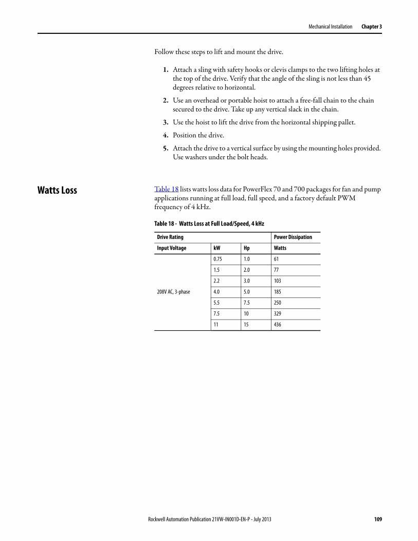
Mechanical Installation Chapter 3
Follow these steps to lift and mount the drive.
1. Attach a sling with safety hooks or clevis clamps to the two lifting holes at the top of the drive. Verify that the angle of the sling is not less than 45 degrees relative to horizontal.
2. Use an overhead or portable hoist to attach a free-fall chain to the chain secured to the drive. Take up any vertical slack in the chain.
3. Use the hoist to lift the drive from the horizontal shipping pallet.
4. Position the drive.
5. Attach the drive to a vertical surface by using the mounting holes provided. Use washers under the bolt heads.
Watts Loss Table 18 lists watts loss data for PowerFlex 70 and 700 packages for fan and pump applications running at full load, full speed, and a factory default PWM frequency of 4 kHz.
Table 18 - Watts Loss at Full Load/Speed, 4 kHz
Drive Rating Power Dissipation
Input Voltage kW Hp Watts
208V AC, 3-phase
0.75 1.0 61
1.5 2.0 77
2.2 3.0 103
4.0 5.0 185
5.5 7.5 250
7.5 10 329
11 15 436
Rockwell Automation Publication 21VW-IN001D-EN-P - July 2013 109

Chapter 3 Mechanical Installation
480V AC, 3-phase
0.75 1.0 57
1.5 2.0 75
2.2 3.0 99
4.0 5.0 138
5.5 7.5 178
7.5 10 235
11 15 350
15 20 486
18.5 25 414
22 30 448
30 40 561
37 50 700
45 60 940
55 75 1117
75 100 1489
90 125 1855
110 150 2214
132 200 2512
600V AC, 3-phase
2.2 3.0 89
4.0 5.0 128
5.5 7.5 168
7.5 10 226
11 15 340
15 20 433
18.5 25 334
22 30 365
30 40 452
37 50 571
45 60 835
55 75 1371
75 100 1884
90 125 1910
110 150 2290
Table 18 - Watts Loss at Full Load/Speed, 4 kHz (Continued)
Drive Rating Power Dissipation
Input Voltage kW Hp Watts
110 Rockwell Automation Publication 21VW-IN001D-EN-P - July 2013

Mechanical Installation Chapter 3
Weights Table 19 through Table list approximate weights for PowerFlex 70 and 700 drive packages for fan and pump applications.
Table 19 - Weights for Main Input Disconnect Packages (style A)
Input Voltage kW Hp Input Line Reactor Weight
kg (lb)
208V AC
0.75 1
No
11.3 (25)
1.5 2 11.3 (25)
2.2 3 11.3 (25)
4 5 15.4 (34)
5.5 7.5 18.1 (40)
7.5 10 18.1 (40)
11 15 18.5 (41)
0.75 1
Yes
17.6 (39)
1.5 2 17.6 (39)
2.2 3 17.6 (39)
4 5 22.6 (50)
5.5 7.5 28.1 (62)
7.5 10 28.1 (62)
Rockwell Automation Publication 21VW-IN001D-EN-P - July 2013 111

Chapter 3 Mechanical Installation
480V AC
0.75 1.0
No
11.3 (25)
1.5 2.0 11.3 (25)
2.2 3.0 11.3 (25)
4.0 5.0 11.3 (25)
5.5 7.5 15.4 (34)
7.5 10 15.4 (34)
11 15 18.1 (40)
15 20 18.1 (40)
18.5 25 18.1 (40)
22 30 22.6 (50)
30 40 31.2 (69)
37 50 31.2 (69)
45 60 68.0 (150)
55 75 68.0 (150)
75 100 68.0 (150)
90 125 176.9 (390)
110 150 176.9 (390)
132 200 176.9 (390)
0.75 1.0
Yes
17.6 (39)
1.5 2.0 17.6 (39)
2.2 3.0 17.6 (39)
4.0 5.0 17.6 (39)
5.5 7.5 22.6 (50)
7.5 10 22.6 (50)
11 15 28.1 (62)
15 20 28.1 (62)
18.5 25 28.1 (62)
Table 19 - Weights for Main Input Disconnect Packages (style A) (Continued)
Input Voltage kW Hp Input Line Reactor Weight
kg (lb)
112 Rockwell Automation Publication 21VW-IN001D-EN-P - July 2013

Mechanical Installation Chapter 3
600V AC
2.2 3.0
No
11.3 (25)
4.0 5.0 11.3 (25)
5.5 7.5 15.4 (34)
7.5 10 15.4 (34)
11 15 18.1 (40)
15 20 18.1 (40)
18.5 25 18.1 (40)
22 30 22.6 (50)
30 40 31.2 (69)
37 50 31.2 (69)
45 60 68.0 (150)
55 75 68.0 (150)
75 100 68.0 (150)
90 125 176.9 (390)
110 150 176.9 (390)
2.2 3.0
Yes
17.6 (39)
4.0 5.0 17.6 (39)
5.5 7.5 22.6 (50)
7.5 10 22.6 (50)
11 15 28.1 (62)
15 20 28.1 (62)
18.5 25 28.1 (62)
Table 19 - Weights for Main Input Disconnect Packages (style A) (Continued)
Input Voltage kW Hp Input Line Reactor Weight
kg (lb)
Rockwell Automation Publication 21VW-IN001D-EN-P - July 2013 113

Chapter 3 Mechanical Installation
Table 20 - Weights for Three-contactor Full-feature Bypass with Disconnect Packages(style B)
Input Voltage kW Hp Input Line Reactor Weight
kg (lb)
208V AC
0.75 1
No
15.8 (35)
1.5 2 15.8 (35)
2.2 3 15.8 (35)
4 5 21.3 (47)
5.5 7.5 27.2 (60)
7.5 10 27.2 (60)
11 15 27.2 (60)
0.75 1
Yes
22.2 (49)
1.5 2 22.2 (49)
2.2 3 22.2 (49)
4 5 29.4 (65)
5.5 7.5 37.6 (83)
7.5 10 37.6 (83)
114 Rockwell Automation Publication 21VW-IN001D-EN-P - July 2013

Mechanical Installation Chapter 3
480V AC
0.75 1.0
No
15.8 (35)
1.5 2.0 15.8 (35)
2.2 3.0 15.8 (35)
4.0 5.0 15.8 (35)
5.5 7.5 21.3 (47)
7.5 10 21.3 (47)
11 15 27.2 (60)
15 20 27.2 (60)
18.5 25 27.2 (60)
22 30 43.0 (95)
30 40 43.0 (95)
37 50 43.0 (95)
45 60 108.8 (240)
55 75 113.3 (250)
75 100 122.4 (270)
90 125 190.5 (420)
110 150 190.5 (420)
0.75 1.0
Yes
22.2 (49)
1.5 2.0 22.2 (49)
2.2 3.0 22.2 (49)
4.0 5.0 22.2 (49)
5.5 7.5 29.4 (65)
7.5 10 29.4 (65)
11 15 37.6 (83)
15 20 37.6 (83)
18.5 25 37.6 (83)
Table 20 - Weights for Three-contactor Full-feature Bypass with Disconnect Packages(style B) (Continued)
Input Voltage kW Hp Input Line Reactor Weight
kg (lb)
Rockwell Automation Publication 21VW-IN001D-EN-P - July 2013 115

Chapter 3 Mechanical Installation
600V AC
2.2 3.0
No
15.8 (35)
4.0 5.0 15.8 (35)
5.5 7.5 21.3 (47)
7.5 10 21.3 (47)
11 15 27.2 (60)
15 20 27.2 (60)
18.5 25 27.2 (60)
22 30 43.0 (95)
30 40 43.0 (95)
37 50 43.0 (95)
45 60 108.8 (240)
55 75 113.3 (250)
75 100 122.4 (270)
90 125 190.5 (420)
110 150 190.5 (420)
2.2 3.0
Yes
22.2 (49)
4.0 5.0 22.2 (49)
5.5 7.5 29.4 (65)
7.5 10 29.4 (65)
11 15 37.6 (83)
15 20 37.6 (83)
18.5 25 37.6 (83)
Table 20 - Weights for Three-contactor Full-feature Bypass with Disconnect Packages(style B) (Continued)
Input Voltage kW Hp Input Line Reactor Weight
kg (lb)
116 Rockwell Automation Publication 21VW-IN001D-EN-P - July 2013

Appendix A
Technical Specifications
Environmental Specifications This appendix lists the environmental specifications for the drives. For all other specifications, refer to the user manual for the drive listed in the table below.
Table 21 - Pollution Degree Ratings According to EN 61800-5-1
Fuse, Circuit Breaker, and Short Circuit Current Specifications
For fuse, circuit breaker, and short circuit current rating specifications for the packaged fan and pump applications, refer to PowerFlex 70 and 700 Packages for Fan and Pump Applications Product Information, publication 21VW-PC001.
Category Attribute Value
Environment
Altitude 1000 m (3300 ft) max without derating
Surrounding air temperature without derating 0 …40 °C (32…104 °F)
Storage temperature (all const.) -40…70 °C (-40…158 °F)
Relative humidity 5… 95% noncondensing
Shock 15 G peak for 11 ms duration (±1.0 ms)
Vibration 0.152 mm (0.006 in.) displacement, 1 G peak, 5.5 Hz
Surrounding environmentPollution degree:
Pollution degree 1 and 2Pollution degree 3 and 4
See Table 21 on page 117 for descriptions of pollution degree rating.
All enclosures are acceptable for pollution degree 1 and 2.An enclosure that meets or exceeds IP54, NEMA/UL Type 12, is required for pollution degree 3 and 4.
Other specifications
For other specifications, refer to the PowerFlex 70 Adjustable Frequency AC Drives User Manual, publication 20A-UM001, or the PowerFlex 700 Adjustable Frequency AC Drive User Manual, publication 20B-UM001.
Pollution Degree
Description
1 No pollution or only dry non-conductive pollution occurs. The pollution has no influence.
2 Normally only non-conductive pollution occurs. Occasionally a temporary conductivity, caused by condensation, is expected when the drive is out of operation.
3 Conductive pollution or dry non-conductive pollution occurs, which becomes conductive due to condensation, and is expected.
4 The pollution generates persistent conductivity caused, for example, by conductive dust, rain, or snow.
Rockwell Automation Publication 21VW-IN001D-EN-P - July 2013 117

Appendix A Technical Specifications
Notes:
118 Rockwell Automation Publication 21VW-IN001D-EN-P - July 2013

Appendix B
Replacement Parts
Main Input Disconnect Package (style A)
Table 22 provides a list of replacement part numbers for the main input disconnect package (style A).Table 22 - Main Input Disconnect Package Replacement Parts (style A)
Description Designation Voltage Hp Part No. Manufacturer
Disconnect switch DSI
208V AC
1…5 194R-J30-1753
Allen-Bradley
7.5…10 194R-J60-1753
15 194R-J100-1753
480V AC
1…10 194R-J30-1753
15…25 194R-J60-1753
30…50 194R-J100-1753
60…100 194R-J200-1753
125…200 194R-J400-1753
600V AC
3…10 194R-J30-1753
15…25 194R-J60-1753
30…50 194R-J100-1753
60…100 194R-J200-1753
125…150 194R-J400-1753
Operator handle –
208V AC 1…15 194R-PB
480V AC1…25 194R-PB
30…200 194R-HM4
600V AC3…25 194R-PB
30…150 194R-HM4
Operator shaft –
208V AC1…10 194R-S2
15 194R-R4
480V AC
1…25 194R-S2
30…100 194R-R4
125…200 194R-R6
600V AC
1…25 194R-S2
30…100 194R-R4
125…150 194R-R6
Rockwell Automation Publication 21VW-IN001D-EN-P - July 2013 119

Appendix B Replacement Parts
Main fuses FU1…FU3
208V AC
1 10 Amp Class J –
2 15 Amp Class J –
3…5 20 Amp Class J –
7.5 35 Amp Class J –
10 40 Amp Class J –
15 80 Amp Class J –
480V AC
1 6 Amp Class J –
2…3 10 Amp Class J –
5 15 Amp Class J –
7.5…10 20 Amp Class J –
15…20 35 Amp Class J –
25 60 Amp Class J –
30 70 Amp Class J –
40 80 Amp Class J –
50 100 Amp Class J –
60 150 Amp Class J –
75 175 Amp Class J –
100 200 Amp Class J –
125 250 Amp Class J –
150 350 Amp Class J –
200 400 Amp Class J –
600V AC
3 10 Amp Class J –
5 15 Amp Class J –
7.5…10 20 Amp Class J –
15…20 35 Amp Class J –
25 60 Amp Class J –
30 70 Amp Class J –
40 80 Amp Class J –
50 100 Amp Class J –
60 150 Amp Class J –
75 175 Amp Class J –
100 200 Amp Class J –
125 250 Amp Class J –
150 350 Amp Class J –
Table 22 - Main Input Disconnect Package Replacement Parts (style A) (Continued)
Description Designation Voltage Hp Part No. Manufacturer
120 Rockwell Automation Publication 21VW-IN001D-EN-P - July 2013

Replacement Parts Appendix B
Drive module DM1
208V AC
1 20AB4P2A0AYNANC0
Allen-Bradley
2 20AB6P8A0AYNANC0
3 20AB9P6A0AYNANC0
5 20AB015A0AYNANC0
7.5 20AB022A0AYNANC0
10 20AB028A0AYNANC0
15 20AB042A0AYNANC0
480V AC
1 20AD2P1A0AYNANC0
2 20AD3P4A0AYNANC0
3 20AD5P0A0AYNANC0
5 20AD8P0A0AYNANC0
7.5 20AD011A0AYNANC0
10 20AD014A0AYNANC0
15 20AD022A0AYNANC0
20 20AD027A0AYNANC0
25 20AD034A0AYNANC0
30 20AD040A0AYNANC0
40 20AD052A0AYNANC0
50 20AD065A0AYNANC0
60 20BD077A0ANNANA0
75 20BD096A0ANNANA0
100 20BD125A0ANNANA0
125 20BD156A0ANNANA0
150 20BD180A0ANNANA0
200 20BD248A0ANNANA0
Table 22 - Main Input Disconnect Package Replacement Parts (style A) (Continued)
Description Designation Voltage Hp Part No. Manufacturer
Rockwell Automation Publication 21VW-IN001D-EN-P - July 2013 121

Appendix B Replacement Parts
Drive module DM1 600V AC
3 20AE3P9A0AYNNNC0
Allen-Bradley
5 20AE6P1A0AYNNNC0
7.5 20AE9P0A0AYNNNC0
10 20AE011A0AYNNNC0
15 20AE017A0AYNNNC0
20 20AE022A0AYNNNC0
25 20BE027A0AYNANA0
30 20BE032A0AYNANA0
40 20BE041A0AYNANA0
50 20BE052A0AYNANA0
60 20BE062A0AYNANA0
75 20BE077A0AYNANA0
100 20BE099A0AYNANA0
125 20BE125A0AYNANA0
150 20BE144A0AYNANA0
Table 22 - Main Input Disconnect Package Replacement Parts (style A) (Continued)
Description Designation Voltage Hp Part No. Manufacturer
122 Rockwell Automation Publication 21VW-IN001D-EN-P - July 2013

Replacement Parts Appendix B
Three-contactor Full-feature Bypass with Disconnect Package (style B)
Table 23 provides a list of replacement part numbers for the 3-contactor full-feature bypass with disconnect package (style B).Table 23 - Three-contactor Full-feature Bypass with Disconnect Package Replacement Parts(style B)
Description Designation Voltage Hp Part Number Manufacturer
Disconnect switch DSI
208V AC
1…5 194R-J30-1753
Allen-Bradley
7.5…10 194R-J60-1753
15 194R-J100-1753
480V AC
1…10 194R-J30-1753
15…25 194R-J60-1753
30…50 194R-J100-1753
60…100 194R-J200-1753
125…150 194R-J400-1753
600V AC
3…10 194R-J30-1753
15…25 194R-J60-1753
30…50 194R-J100-1753
60…100 194R-J200-1753
125…150 194R-J400-1753
Operator handle –
208V AC 1…15 194R-PB
480V AC1…25 194R-PB
30…150 194R-HM4
600V AC3…25 194R-PB
30…150 194R-HM4
Operator shaft –
208V AC1…10 194R-S2
15 194R-R4
480V AC
1…25 194R-S2
30…100 194R-R4
125…150 194R-R6
600V AC
3…25 194R-S2
30…100 194R-R4
125…150 194R-R6
Rockwell Automation Publication 21VW-IN001D-EN-P - July 2013 123

Appendix B Replacement Parts
Main fuses FU1…FU3
208V AC
1 10 Amp Class J –
2 15 Amp Class J –
3…5 20 Amp Class J –
7.5 35 Amp Class J –
10 40 Amp Class J –
15 80 Amp Class J –
480V AC
1 6 Amp Class J –
2…3 10 Amp Class J –
5 15 Amp Class J –
15…20 35 Amp Class J –
25 60 Amp Class J –
30 70 Amp Class J –
40 80 Amp Class J –
50 100 Amp Class J –
60 150 Amp Class J –
75 175 Amp Class J –
100 200 Amp Class J –
125 250 Amp Class J –
150 350 Amp Class J –
600V AC
3 10 Amp Class J –
5 15 Amp Class J –
7.5…10 20 Amp Class J –
15…20 35 Amp Class J –
25 60 Amp Class J –
30 70 Amp Class J –
40 80 Amp Class J –
50 100 Amp Class J –
60 150 Amp Class J –
75 175 Amp Class J –
100 200 Amp Class J –
125 250 Amp Class J –
150 350 Amp Class J –
Table 23 - Three-contactor Full-feature Bypass with Disconnect Package Replacement Parts(style B) (Continued)
Description Designation Voltage Hp Part Number Manufacturer
124 Rockwell Automation Publication 21VW-IN001D-EN-P - July 2013

Replacement Parts Appendix B
Control transformer T1
208V AC1…10 TB-69300
ACME
15 TB-69301
480V AC
1…20 TB-69300
25…60 TB-69301
75…150 TB-69302
600V AC
3…20 TB-81001
25…60 TB-81001
75…150 TB-81002
Control transformer fuses FU4, FU5
208V AC1…10 1 Amp Class CC –
15 2 Amp Class CC –
480V AC1…60 1 Amp Class CC –
75…150 2 Amp Class CC –
600V AC3…60 1 Amp Class CC –
75…150 2 Amp Class CC –
Bypass contactor BC
208V AC
1…3 100-C16D10
Allen-Bradley
5 100-C23D10
7.5…10 100-C37D00
15 100-C60D00
480V AC
1…10 100-C16D10
15…20 100-C37D10
25…30 100-C43D00
40 100-C60D00
50 100-C72D00
60 100-C85D00
75 100-D115ED11
100 100-D140ED11
125 100-D180ED11
150 100-D210ED11
600V AC
3…10 100-C16D10
15 100-C23D10
20 100-C30D10
25…30 100-C43D00
40 100-C60D00
50 100-C72D00
60 100-C85D00
75…100 100-D115ED11
125 100-D140ED11
150 100-D210ED11
Table 23 - Three-contactor Full-feature Bypass with Disconnect Package Replacement Parts(style B) (Continued)
Description Designation Voltage Hp Part Number Manufacturer
Rockwell Automation Publication 21VW-IN001D-EN-P - July 2013 125

Appendix B Replacement Parts
Drive input contactor DIC
208V AC
1…5 100-C16D10
Allen-Bradley
7.5 100-C23D10
10 100-C37D00
15 100-C60D00
480V AC
1…10 100-C16D10
15…20 100-C23D10
25…30 100-C43D00
40 100-C60D00
50 100-C72D00
60 100-C85D00
75…100 100-D115ED11
125 100-D140ED11
150 100-D210ED11
600V AC
3…10 100-C16D10
15 100-C23D10
20 100-C30D10
25…30 100-C43D00
40 100-C60D00
50 100-C72D00
60 100-C85D00
75…100 100-D115ED11
125 100-D140ED11
150 100-D210ED11
Table 23 - Three-contactor Full-feature Bypass with Disconnect Package Replacement Parts(style B) (Continued)
Description Designation Voltage Hp Part Number Manufacturer
126 Rockwell Automation Publication 21VW-IN001D-EN-P - July 2013

Replacement Parts Appendix B
Drive output contactor DOC
208V AC
1…7.5 100-C16D10
Allen-Bradley
10 100-C37D00
15 100-C60D00
480V AC
1…20 100-C16D10
25…30 100-C37D00
40 100-C43D00
50…60 100-C72D00
75 100-C85D00
100…125 100-D115ED11
150 100-D140ED11
600V AC
3…20 100-C16D10
25…30 100-C37D00
40 100-C43D00
50…60 100-C72D00
75 100-C85D00
100…125 100-D115ED11
150 100-D140ED11
Overload relay OL
208V AC
1…3 193-EEDB
5 193-EEEB
7.5 193-EEED
10 193-EEFD
15 193-EEGE
480V AC
1…2 193-EECB
3…7.5 193-EEDB
10 193-EEEB
15 193-EEED
20…30 193-EEFD
40…60 193-EEGE
75 193-EEVF
100 193-EEHF
125 193-EEJF
150 193-EEJG
Table 23 - Three-contactor Full-feature Bypass with Disconnect Package Replacement Parts(style B) (Continued)
Description Designation Voltage Hp Part Number Manufacturer
Rockwell Automation Publication 21VW-IN001D-EN-P - July 2013 127

Appendix B Replacement Parts
Overload relay OL 600V AC
3…10 193-EEDB
Allen-Bradley
15 193-EEEB
20 193-EEED
25…30 193-EEFD
40…60 193-EEGE
75…100 193-EEVF
125 193-EEHF
150 193-EEJG
Bypass control panel CP1
208V AC 1…15 SK-C1-BCP1
480V AC 1…150 SK-C1-BCP1
600V AC 3…150 SK-C1-BCP1
Power terminal blocks T1…T3
208V AC1…7.5 1492-W10
10…15 1492-W16S
480V AC
1…15 1492-W10
20…30 1492-W16S
40…75 1492-J35
100 67013Mersen
125…150 67003
600V AC
3…15 1492-W10
Allen-Bradley20…30 1492-W16S
40…75 1492-J35
100 67013Mersen
125…150 67003
Control terminal blocks T31…T40
208V AC 1…15 1492-W4
Allen-Bradley480V AC 1…150 1492-W4
600V AC 3…150 1492-W4
Table 23 - Three-contactor Full-feature Bypass with Disconnect Package Replacement Parts(style B) (Continued)
Description Designation Voltage Hp Part Number Manufacturer
128 Rockwell Automation Publication 21VW-IN001D-EN-P - July 2013

Replacement Parts Appendix B
Drive module DM1
208V AC
1 20AB4P2A0AYNANC0
Allen-Bradley
2 20AB6P8A0AYNANC0
3 20AB9P6A0AYNANC0
5 20AB015A0AYNANC0
7.5 20AB022A0AYNANC0
10 20AB028A0AYNANC0
15 20AB042A0AYNANC0
480V AC
1 20AD2P1A0AYNANC0
2 20AD3P4A0AYNANC0
3 20AD5P0A0AYNANC0
5 20AD8P0A0AYNANC0
7.5 20AD011A0AYNANC0
10 20AD014A0AYNANC0
15 20AD022A0AYNANC0
20 20AD027A0AYNANC0
25 20AD034A0AYNANC0
30 20AD040A0AYNANC0
40 20AD052A0AYNANC0
50 20AD065A0AYNANC0
60 20BD077A0ANNANA0
75 20BD096A0ANNANA0
100 20BD125A0ANNANA0
125 20BD156A0ANNANA0
150 20BD180A0ANNANA0
Drive module DM1 600V AC
3 20AE3P9A0AYNNNC0
5 20AE6P1A0AYNNNC0
7.5 20AE9P0A0AYNNNC0
10 20AE011A0AYNNNC0
15 20AE017A0AYNNNC0
20 20AE022A0AYNNNC0
25 20BE027A0AYNANA0
30 20BE032A0AYNANA0
40 20BE041A0AYNANA0
50 20BE052A0AYNANA0
60 20BE062A0ANNANA0
75 20BE077A0ANNANA0
100 20BE099A0ANNANA0
125 20BE125A0ANNANA0
150 20BE144A0ANNANA0
Table 23 - Three-contactor Full-feature Bypass with Disconnect Package Replacement Parts(style B) (Continued)
Description Designation Voltage Hp Part Number Manufacturer
Rockwell Automation Publication 21VW-IN001D-EN-P - July 2013 129

Appendix B Replacement Parts
Notes:
130 Rockwell Automation Publication 21VW-IN001D-EN-P - July 2013

Index
Bbranch circuit protection
main input disconnect (style A) 11three-contactor full-feature bypass (style B)
52bus capacitor test points 8bus capacitors, discharging 8bypass control interface
selector switch 56status indicators 56
Ccapacitors
bus, discharging 8catalog number explanation 9catalog numbers 9command and reference selection 63contactors
bypass (BC) 53drive input (DIC) 53drive output (DOC) 53
control over a communication network 63control transformer 55conventions, manual 7customer-supplied contacts
three-contactor full-feature bypass (style B) only
autostart 61bypass 61bypass running 62freeze/fire stat 61interlock 61purge 62
Eelectric shock hazard 8environment 107environment specifications 117ESD precautions 8ESD, static discharge 8
Ffuses
main input disconnect (style A) 11three-contactor full-feature bypass (style B)
52
Ggeneral precautions 8
Iinter-connect drawings
main input disconnect (style A) 27three-contactor full-feature bypass (style B)
83
Llayout drawings
main input disconnect (style A) 30three-contactor full-feature bypass (style B)
86lifting and mounting the drive 108
Mmain disconnect switch
main input disconnect (style A) 11three-contactor full-feature bypass (style B)
51main fuses
main input disconnect (style A) 11three-contactor full-feature bypass (style B)
52manual conventions 7manuals
additional information 10user manuals 7
maximum surrounding air temperature 107mechanical installation 107motor overload relay 53mounting
clearances, min 107considerations 107the drive 108
Ooperating modes
three-contactor full-feature bypass (style B)bypass mode 62drive mode 62drive test mode 62
outline drawingsmain input disconnect (style A) 40three-contactor full-feature bypass (style B)
95overload ratings
three-contactor full-feature bypass (style B) 54
overload relaythree-contactor full-feature bypass (style B)
53
Rockwell Automation Publication 21VW-IN001D-EN-P - July 2013 131

Index
Pparameters and programming
main input disconnect (style A) 17three-contactor full-feature bypass (style B)
64power dissipation 109precautions, general 8programming and parameters 7
Rreplacement parts
main input disconnect (style A) 119three-contactor full-feature bypass (style B)
123
Sschematics
main input disconnect (style A) 24three-contactor full-feature bypass (style B)
71specifications 7, 117starting the drive 7static discharge, ESD 8supplemental information 117
Ttechnical support 10terminal block specifications
I/Omain input disconnect (style A) 16three-contactor full-feature bypass
(style B) 60input power
main input disconnect (style A) 14three-contactor full-feature bypass
(style B) 57output power
main input disconnect (style A) 15three-contactor full-feature bypass
(style B) 59troubleshooting 7
Wwatts loss 109weights, approximate 111
132 Rockwell Automation Publication 21VW-IN001D-EN-P - July 2013


Publication 21VW-IN001D-EN-P - July 2013 Supersedes Publication 21VW-IN001C-EN-P - May 2007 Copyright © 2013 Rockwell Automation, Inc. All rights reserved. Printed in the U.S.A.
Rockwell Automation Support
Rockwell Automation provides technical information on the Web to assist you in using its products.At http://www.rockwellautomation.com/support you can find technical and application notes, sample code, and links to software service packs. You can also visit our Support Center at https://rockwellautomation.custhelp.com/ for software updates, support chats and forums, technical information, FAQs, and to sign up for product notification updates.
In addition, we offer multiple support programs for installation, configuration, and troubleshooting. For more information, contact your local distributor or Rockwell Automation representative, or visithttp://www.rockwellautomation.com/services/online-phone.
Installation Assistance
If you experience a problem within the first 24 hours of installation, review the information that is contained in this manual. You can contact Customer Support for initial help in getting your product up and running.
New Product Satisfaction Return
Rockwell Automation tests all of its products to help ensure that they are fully operational when shipped from the manufacturing facility. However, if your product is not functioning and needs to be returned, follow these procedures.
Documentation Feedback
Your comments will help us serve your documentation needs better. If you have any suggestions on how to improve this document, complete this form, publication RA-DU002, available at http://www.rockwellautomation.com/literature/.
United States or Canada 1.440.646.3434
Outside United States or Canada Use the Worldwide Locator at http://www.rockwellautomation.com/rockwellautomation/support/overview.page, or contact your local Rockwell Automation representative.
United States Contact your distributor. You must provide a Customer Support case number (call the phone number above to obtain one) to your distributor to complete the return process.
Outside United States Please contact your local Rockwell Automation representative for the return procedure.
Rockwell Otomasyon Ticaret A.Ş., Kar Plaza İş Merkezi E Blok Kat:6 34752 İçerenköy, İstanbul, Tel: +90 (216) 5698400