Agilent AA Spectrometer Systems
60
Agilent AA Spectrometer Systems Site Preparation Guide
Transcript of Agilent AA Spectrometer Systems

Agilent AA Spectrometer Systems
Site Preparation Guide

2 Agilent AA Spectrometer Systems Site Preparation Guide
Notices © Agilent Technologies, Inc. 1994, 1995, 1997, 1998, 2000–2003, 2007, 2010 and 2012-2013, 2016-2017
No part of this manual may be reproduced in any form or by any means (including electronic storage and retrieval or translation into a foreign language) without prior agreement and written consent from Agilent Technologies, Inc. as governed by United States and international copyright laws.
Manual Part Number 8510119300
Edition Sixteenth edition, February 2017
Agilent Technologies Australia [M] Pty Ltd
679 Springvale Road
Mulgrave, Victoria, 3170, Australia
Warranty The material contained in this document is provided “as is,” and is subject to being changed, without notice, in future editions. Further, to the maximum extent permitted by applicable law, Agilent disclaims all warranties, either express or implied, with regard to this manual and any information contained herein, including but not limited to the implied warranties of merchantability and fitness for a particular purpose. Agilent shall not be liable for errors or for incidental or consequential damages in connection with the furnishing, use, or performance of this document or of any information contained herein. Should Agilent and the user have a separate written agreement with warranty terms covering the material in this document that conflict with these terms, the warranty terms in the separate agreement shall control.
Technology Licenses The hardware and/or software described in this document are furnished under a license and may be used or copied only in accordance with the terms of such license.
Restricted Rights Legend If software is for use in the performance of a U.S. Government prime contract or subcontract, Software is delivered and licensed as “Commercial computer software” as defined in DFAR 252.227-7014 (June 1995), or as a “commercial item” as defined in FAR 2.101(a) or as “Restricted computer software” as defined in FAR 52.227-19 (June 1987) or any equivalent agency regulation or
contract clause. Use, duplication or disclosure of Software is subject to Agilent Technologies’ standard commercial license terms, and non-DOD Departments and Agencies of the U.S. Government will receive no greater than Restricted Rights as defined in FAR 52.227-19(c)(1-2) (June 1987). U.S. Government users will receive no greater than Limited Rights as defined in FAR 52.227-14 (June 1987) or DFAR 252.227-7015 (b)(2) (November 1995), as applicable in any technical data.
Safety Notices
A CAUTION notice denotes a hazard. It calls attention to an operating procedure, practice, or the like that, if not correctly performed or adhered to, could result in damage to the product or loss of important data. Do not proceed beyond a CAUTION notice until the indicated conditions are fully understood and met.
A WARNING notice denotes a hazard. It calls attention to an operating procedure, practice, or the like that, if not correctly performed or adhered to, could result in personal injury or death. Do not proceed beyond a WARNING notice until the indicated conditions are fully understood and met.
WARNING
CAUTION
Request for Installation
Agilent AA Spectrometer Systems Site Preparation Guide 3
Request for Installation All preparations have been completed in accordance with the information provided in the Agilent AA Systems Site Preparation Guide. Please arrange for the installation to be completed as soon as possible. I understand that if the installation site is not prepared in accordance with the enclosed instructions, additional installation charges may apply.
Company name:
Company address:
Name: Position:
Telephone: Preferred installation date:
Signed: Date:
Site Preparation Checklist Your site must meet all requirements before you request installation. After completing each requirement, place a check in the appropriate check box. Ensure you compare each box with the supplied packing list.
On completion of the site preparation, send this completed Site Preparation Checklist to your local Agilent agent or Agilent sales and service office. As soon as it is received, Agilent or its agent will contact you to arrange a convenient time for installation.
Any instrument damage has been reported to the company responsible for transporting the instrument. An Agilent representative was informed of the damage, and a copy of the damage report has been sent to the Agilent office.
21 CFR Part 11 site preparation requirements
N/A (Check if 21 CFR Part 11 is not required.)
The 21 CFR Part 11 booklet has been received and read, and action has been taken to ensure Section 4 of the 21 CFR Part 11 booklet has been completed.
The System Administrator has been notified.
Arrangements have been made for the System Administrator to be present during installation.
Site Preparation Checklist
4 Agilent AA Spectrometer Systems Site Preparation Guide
Requirement Principal installation area is in compliance with all relevant safety regulations. Telephone outlet near instrument. PC components on site. Brand: Processor: RAM in MB: Hard disk size in MB: Operating system:
Printer brand: Model number:
Laboratory is free of excessive particulate matter. Lab temperature maintained between 20 and 25 °C (68 and 77 °F). Workbench requirements met. Exhaust system is suitable. Specified electrical supply and power outlets installed. All gas supplies (at specified purities), regulators, and gas lines are installed. Waste container appropriate for the chemical waste is prepared. Water cooling/circulation system and power connections are set up. Brand and model number: Serial number:
Entrance to the lab is at least 1450 cm (57.1 in) wide. Accessories SIPS 10/20 Sample Introduction Pump System serial number: SPS Sample Preparation System serial number: VGA 77 Vapor Generation Accessory serial number: GTA Graphite Tube Atomizer serial number: ETC 60 Electrothermal Temperature Controller serial number: Additional accessory serial number: Type and model:
Additional accessory serial number: Type and model:

Contents
Agilent AA Spectrometer Systems Site Preparation Guide 5
Contents
1. Safety Practices and Hazards 9
General 9
Heat, Vapors and Fumes 10
Compressed Gases and Cylinders 11
Gas Hoses and Connections 12
Other 12
Flame Operation 13 Flammable solvents 13 Compressed gases and cylinders for flame operation 13 Acetylene 13 Nitrous oxide 15 Perchloric acid 15
Flashbacks 16
Furnace and Zeeman Operation 16 Gases 16 Vapors and fumes 16 Magnetic field (Zeeman only) 17
2. Introduction 19
Installation Guidelines 19
Recommended PC Configuration 20
3. Laboratory Environment 21
Suitability 21 Equipment class 21

Contents
6 Agilent AA Spectrometer Systems Site Preparation Guide
Installation category 21 Pollution level 21
Environmental Conditions 22 Cleanliness 22 Temperature, Humidity, and Altitude 22
Noise Levels 23
Workbench 23
Weights and Dimensions 23
4. Laboratory Facilities 31
Exhaust System 31 General 31 Agilent exhaust system 33
Electrical Power Supplies 33
Gas Supplies 36 Pressure cylinder storage 36 Gas connection fittings 37 Permitted gas supplies 38 Gas line diameter 39 Air supply 39 Nitrous oxide supply 42 Acetylene supply 44 Gas supplies for Graphite Tube Atomizers (Zeeman and non-Zeeman) 46 Gas supplies for the Vapor Generation Accessory 46
Waste Fluids 47 Special arrangements for use with organic solvents 48

Contents
Agilent AA Spectrometer Systems Site Preparation Guide 7
Water Cooling System 49
5. Instrument Shipping Information 51
Insurance After Delivery 51
Transit Damage 52
In-House Transit Routes 53
6. Software Installation Guidelines 55
Installing the Microsoft Windows Operating System 55
Installing Agilent SpectrAA Software 56
Installing Agilent SpectrAA CFR Software 56
7. Operator Training 57

Contents
8 Agilent AA Spectrometer Systems Site Preparation Guide
This page is intentionally left blank.

Safety Practices and Hazards
Agilent AA Spectrometer Systems Site Preparation Guide 9
1. Safety Practices and Hazards General 9 Heat, Vapors and Fumes 10 Compressed Gases and Cylinders 11 Gas Hoses and Connections 12 Other 12 Flame Operation 13 Flammable solvents 13 Compressed gases and cylinders for flame operation 13 Acetylene 13 Nitrous oxide 15 Perchloric acid 15 Flashbacks 16 Furnace and Zeeman Operation 16
General Your Agilent AA instrument and accessories have been carefully designed so that when used properly you have an accurate, fast, flexible and safe analytical system.
If the equipment is used in a manner not specified by the manufacturer, the protection provided by the equipment may be impaired.
Operation of an atomic absorption spectrometer can involve the use of compressed gases, flames, and hazardous materials including corrosive fluids and flammable liquids. Unskilled, improper, or careless use of this instrument can create explosion hazards, fire hazards, or other hazards which can cause death, serious injury to personnel, or severe damage to equipment and property.

Safety Practices and Hazards
10 Agilent AA Spectrometer Systems Site Preparation Guide
Information on safety practices is provided with your instrument and manuals, and also referenced in your Agilent accessory manuals. Before using your instrument or accessories, you must thoroughly read these safety practices.
Observe all relevant safety practices at all times.
The safety practices described in the User’s Guides are provided to help you operate the instrument safely. Read each safety topic thoroughly before attempting to operate the instrument and always operate the spectrometer in accordance with these safety practices.
Heat, Vapors and Fumes Heat, vapors and fumes generated by flame, furnace and vapor generation methods can be hazardous to personnel.
Heat, vapors and fumes must be extracted from the instrument by an exhaust system. The instrument must be vented into a self-contained arrangement of collector hood, ducting and exhaust fan. The system must be vented to the outside air, never within the building. Locate the system outlet such that the exhaust cannot re-enter the building through any door, window, air conditioning inlet, or other ventilator. Construct the system in accordance with local codes and regulations for ventilation.
The exhaust system must be capable of providing an exhaust ventilation rate of at least 6 cubic meters per minute (200 cubic feet per minute). Locate the exhaust fan at least 3 meters (10 feet) away from the flame and as close to the outlet as possible. The motor must be mounted away from the hot gases, and plastic parts must not be used as they will melt. Fit a back-draft damper to the outlet end of the system. Equip the exhaust fan power supply with an indicator close to the instrument to indicate whether the exhaust fan is on or off. Always switch the exhaust fan on before lighting the flame.
Use fire-proof ducting that is in accordance with your local fire prevention regulations. Locate the ducting away from fire alarms, sprinkler heads and other heat-sensitive devices. Do not make solder joints in the ducting — the hot exhaust in the duct may melt the joint.
Regularly check the system by smoke test to ensure that the exhaust system is working.
Safety Practices and Hazards
Agilent AA Spectrometer Systems Site Preparation Guide 11
When operating the atomic absorption spectrometer, always have the chimney in place to ensure correct ventilation.
Compressed Gases and Cylinders All compressed gases (other than air) can create a hazard if they leak into the atmosphere. Even small leaks in gas supply systems can be dangerous. Any leak (except that of air) can cause an explosion hazard, a fire hazard, or result in an oxygen-deficient atmosphere. Such hazards can cause death, serious injury, asphyxiation, anesthetic effects, and serious damage to equipment and property.
Cylinders must be stored and handled strictly in accordance with local safety codes and regulations. Cylinders must be used and stored only in a vertical position. Secure all cylinders to an immovable structure or a properly constructed cylinder stand. The area in which cylinders are stored must be adequately ventilated to prevent toxic or explosive accumulations. Move cylinders only on a properly constructed trolley.
Keep cylinders cool. This rule applies to every cylinder of compressed gas. Cylinders have pressure relief devices that release the contents of the cylinder if the temperature exceeds 52 °C (125 °F).
Ensure that all cylinders are clearly labeled so that there can be no doubt about the contents. If the cylinder label is not legible, do not use the cylinder — return it to your supplier. Always ensure that you have the correct cylinder before connecting the cylinder to the instrument.
If air is supplied from a compressor, all moisture must be extracted from the air before it is supplied to the gas control module. Moisture can affect the internal components of the gas control system and create a potentially hazardous situation.
Use only approved regulators and hose connectors.
Never attempt to refill cylinders.
Remember that for cylinder connections, left thread fittings are used for fuel; right thread fittings are used for support gases.

Safety Practices and Hazards
12 Agilent AA Spectrometer Systems Site Preparation Guide
When your analytical program is complete, or at the end of the working day, always ensure that all gas supplies are turned off at the cylinders.
Gas Hoses and Connections Even small leaks in gas supply systems can be dangerous. Any leak can create an explosion hazard, a fire hazard, or can result in an oxygen-deficient atmosphere. Such hazards can cause death, serious injury, asphyxiation, anesthetic effects, and serious damage to equipment and property.
Use only approved regulators, connectors and fittings. If in any doubt, consult your local gas supplier or your Agilent representative.
Ensure that all gas connectors and hoses are correctly assembled.
Arrange gas hoses so that they will not be damaged, stepped on, or have things dropped on them.
Never use frayed or damaged hoses.
Perform leak tests at all joints and seals every day before the instrument is used. Test for leaks with a brush and soapy water or a proprietary leak-detecting solution. Never use a naked flame when testing for leaks.
Other Other specific warnings and cautions appear in the manual and in the Help where appropriate, and detail the specific hazard, describe how to avoid it, and specify the possible consequences of not heeding the warning or caution.
NOTE A ‘Note’ message is used to give advice or information.
Safety Practices and Hazards
Agilent AA Spectrometer Systems Site Preparation Guide 13
Flame Operation
Flammable solvents Unskilled, improper, or careless use of flammable solvents in or near an atomic absorption spectrometer can create explosion hazards and fire hazards. These can result in death, or severe personal injury or burns.
Remember at all times that the combination of a flame and flammable solvents can present a serious hazard. All relevant safety practices governing the use of flammable solvents must be strictly followed.
Compressed gases and cylinders for flame operation This spectrometer is to be used only with air, nitrous oxide, and acetylene for flame operation.
Never use oxygen or oxygen-enriched air as the oxidant, because this will result in an explosion.
Never use any gas except acetylene as the fuel gas.
Acetylene Unskilled, improper, or careless use of acetylene can create explosion hazards and fire hazards, which can result in death, severe personal injury or burns.
Use acetylene at pressures lower than 105 kPa (15 psig). At pressures above this level, acetylene can spontaneously explode. Your Agilent AA is designed to operate at fuel supply pressures between 65 and 100 kPa (9.5-14.5 psig). Refer to the Specifications section or the rear of the instrument for the exact range and recommended pressure.
Do not use any tubing or connector that reacts chemically with acetylene. Never pass acetylene through copper tubing, or brass tubing or fittings containing more than 65% copper, since this may provoke an explosion. Never bring acetylene into direct contact with copper, silver, liquid mercury, gaseous chlorine or grease, as an explosion could result.

Safety Practices and Hazards
14 Agilent AA Spectrometer Systems Site Preparation Guide
Use only acetylene that is packed in acetone. Some gas suppliers offer acetylene packed in material other than acetone. While these alternatives may overcome some of the disadvantages of acetone, they may also introduce the more serious problem of corrosion in the gas control module and must not be used with Agilent atomic absorption spectrometers.
If the pressure in the acetylene cylinder is allowed to fall below 700 kPa (100 psig), or the consumption is greater than 1/7 of the cylinder contents per hour, acetone may be carried over from the cylinder and into the spectrometer. Acetone in the spectrometer can damage seals, o-rings and hoses, degrade analytical performance and precipitate flashbacks.
Minimize the amount of acetone that is carried over with the acetylene by:
Replacing cylinders when their content’s pressure drops below 700 kPa (100 psi).
Ensuring that the rate of acetylene drawn off from each cylinder is not excessive.
If high rates of consumption are observed, then connect two or more cylinders in parallel to a manifold. This reduces the rate at which acetylene is drawn from each cylinder.
To reduce the possibility of fire or explosion:
Test the supply ‘plumbing’ regularly for leaks, by using a brush and soapy water or a proprietary leak-detecting solution. (Never use a naked flame when testing for leaks.).
‘Crack’ the cylinder before use by gently opening the valve to check for any drops or spray of acetone. Any cylinder showing acetone should be returned to the supplier for replacement.
Use ‘Instrument Grade’ acetylene that is at least 99.5% pure.
Turn off fuel gas at the cylinder when you have finished your flame analysis.
Refer also to your local regulations governing the use of acetylene.
Safety Practices and Hazards
Agilent AA Spectrometer Systems Site Preparation Guide 15
Nitrous oxide The decompression of high pressure N2O gas at the regulator can cause excessive cooling and eventual freezing of the regulator. To prevent regulator malfunction and possible flashback, the gas should be heated with an in-line or wrap-around heater.
Perchloric acid Aspiration of perchloric acid and perchlorates into a nitrous oxide-acetylene flame can create an explosion hazard, which can result in death or serious injury, including temporary or permanent impairment of hearing.
Do not use perchloric acid unless it is absolutely essential for sample preparation. If perchloric acid must be used, it may be possible to reduce the risk of explosion by taking the following measures:
Use an air-acetylene flame instead of a nitrous oxide-acetylene flame.
Reduce the concentration of perchloric acid and metal in all analytical solutions to the lowest practicable level. The concentration of perchloric acid should be reduced in the digestion stage and further reduced by extending the fuming stage.
Aspirate all solutions for the shortest practicable period.
Aspirate distilled water between samples. Minimize the aspiration of air.
Use separate spray chamber/liquid trap and drain assemblies for perchloric acid analyses and organic solvent analyses to prevent perchloric acid from mixing with organic solvent residues.
NOTE When solvent extractions of perchloric solutions are performed, some of the acid may dissolve in the organic solvent that is subsequently aspirated. Also, if the organic solution is aspirated while floating on the surface of the acid, do not allow the capillary tube to drop below the organic layer and suck up aqueous perchloric acid.

Safety Practices and Hazards
16 Agilent AA Spectrometer Systems Site Preparation Guide
When using perchloric acid, wear approved ear protectors and approved safety glasses, and ensure that all instrument safety covers are in position.
Flashbacks A flashback is an explosion of the gas mixture in the spray chamber, which can occur for a number of reasons. For more details, refer to the AA instrument User’s Guide or the SpectrAA software Help.
Agilent AA spectrometers have a number of safety features in place to prevent flashbacks, and flashbacks are very rare in circumstances where instruments are properly maintained. In the rare event that a flashback does occur, the Agilent AA instrument safety features are designed to safely relieve the pressure and minimize damage. Refer to your AA instrument User’s Guide or the SpectrAA software Help for recommended maintenance procedures to prevent flashbacks.
Furnace and Zeeman Operation
Gases The graphite tube atomizer gas supply system is designed for use with inert gases and air.
Never use pure hydrogen with the graphite tube atomizer, since this could result in leakage and potentially explosive accumulation of hydrogen. You may, however, use a proprietary, pre-packaged mixture of 95% argon (or nitrogen) and 5% hydrogen. Never attempt to create your own mixture of hydrogen and an inert gas for use with the GTA system.
Vapors and fumes The chimney or the optional exhaust accessory must be in place for furnace operation, to ensure that toxic vapors and heat are exhausted.

Safety Practices and Hazards
Agilent AA Spectrometer Systems Site Preparation Guide 17
Magnetic field (Zeeman only) The magnet produces a variable magnetic field of up to 0.8 tesla peak at mains frequency in the workhead during the read stage.
To avoid interference with heart pacemakers or magnetic storage media, keep them at least 300 mm (12 in) from the magnet.
After all safety regulations have been met, check the checklist box: Principal installation area is in compliance with all relevant safety regulations.

Safety Practices and Hazards
18 Agilent AA Spectrometer Systems Site Preparation Guide
This page is intentionally left blank.

Introduction
Agilent AA Spectrometer Systems Site Preparation Guide 19
2. Introduction Installation Guidelines 19 Recommended PC Configuration 20
This publication contains the information required to successfully prepare a site for an Agilent AA system installation. A copy should be retained for validation purposes. If you have difficulty in preparing for the installation, and for details of operator training courses, contact your Agilent sales or field service representative.
NOTE All information in this manual is accurate at the time or publication. For the most current information, contact your local Agilent representative.
Installation Guidelines Allow a minimum of four hours for the installation by an Agilent field service engineer. If accessories are included, allow a maximum of 8 hours.
The installation will include:
Spectrometer installation
Basic customer training
Maintenance overview
Accessory installation
NOTE Installation time will increase if qualification services (IQ/OQ) are required. Contact your local Agilent field service engineer for further details.
Introduction
20 Agilent AA Spectrometer Systems Site Preparation Guide
Recommended PC Configuration If you are supplying your own personal computer (PC) for use with an Agilent AA instrument, the recommended configuration is shown below.
Table 1. Recommended PC configuration
1 GHz 64-bit (x86) dual core processor or higher
8 GB RAM
500 GB Hard disk drive
256 MB Graphics card supporting 1024 x 768 resolution
DVD-ROM drive
Integrated audio/sound card and speakers
Keyboard and Mouse
19 in LCD Monitor
Microsoft Windows 7 Professional 64-bit (Service Pack 1) or Microsoft Windows 10 Professional 64-bit operating systems
NOTE The PC must have one spare full height PCI expansion slot for the Agilent PCI-IEEE interface card or use the USB-GPIB-HS converter.
If SPS 3 Autosampler or ETC 60 accessories are being used an RS232 port is required for each of these.
A USB port is required if the camera option or an SPS 4 Autosampler is to be used.
Locate the PC keyboard and mouse for ergonomically correct access.
If you are using a PC not purchased from Agilent Technologies, refer to the documentation supplied with Microsoft Windows for instructions on installing the Windows operating system. It is the responsibility of the customer to ensure that the Microsoft Windows operating system is installed on the computer.
After the PC requirements have been met, enter the requested information and then check the checklist box: PC components on site.
Laboratory Environment
Agilent AA Spectrometer Systems Site Preparation Guide 21
3. Laboratory Environment Suitability 21 Environmental Conditions 22 Noise Levels 23 Workbench 23 Weights and Dimensions 23
Suitability
Equipment class Your Agilent AA instrument is designed for indoor use only and is classified suitable under Equipment Class I category.
Installation category The installation category is II, based on IEC61010-1. The installation category implies the regulation for impulse withstand voltage. It is also called the ‘Over voltage category’. ‘II’ applies to electrical equipment with a nominal supply voltage up to 300 V.
Pollution level The pollution level is 2, based on IEC61010-1. Pollution level describes the degree to which a solid, liquid, or gas that deteriorates dielectric strength is adhering. ‘2’ applies to a normal indoor atmosphere, where only nonconductive pollution occurs.

Laboratory Environment
22 Agilent AA Spectrometer Systems Site Preparation Guide
Environmental Conditions
Cleanliness The area selected for operation of an Agilent AA spectrometer system must be free from drafts, corrosive atmospheres and vibration. Sample preparation areas and materials storage facilities should be located in a separate room.
The area should have a dust-free, low-humidity atmosphere. Air conditioning is strongly recommended for control of the environment. The instrument should not be located near a window, door or any other area where drafts may cause unstable thermal conditions.
After the cleanliness requirements have been met, check the checklist box: Laboratory is free of excessive particulate matter.
Temperature, Humidity, and Altitude
Table 2. Recommended environmental conditions for Agilent AA spectrometers
Altitude Temperature range
Relative humidity (non-condensing)
For operation 0 to 853 m (0 to 2800 ft)
10 to 35 °C (50 to 95 °F)
8 to 80%
853 to 2133 m (2800 to 7000 ft)
10 to 25 °C (50 to 77 °F)
8 to 80%
For storage 0 to 2133 m (0 to 7000 ft)
5 to 45 °C (40 to 115 °F)
20 to 80%
NOTE For optimum analytical performance, it is recommended that the ambient temperature of the laboratory be between 20 and 25 °C (68 and 77 °F).and be held constant to within ±2 °C (±3.6 °F) throughout the entire working day.
After the temperature requirements have been met, check the checklist box: Lab temperature maintained between 20 and 25 °C (68 and 77 °F).

Laboratory Environment
Agilent AA Spectrometer Systems Site Preparation Guide 23
Noise Levels The sound pressure level (SPL) of a flame AA in a ‘normal’ laboratory environment (≈60 dBA) ambient noise measured at normal operator position is ≈65 dBA. At a distance of 1 meter from the instrument, the SPL is reduced to ≈62 dBA. The likely maximum SPL at a customer location will be greatly influenced by the extraction system.
Workbench The workbench must be free from vibration, and be stable and strong enough to support the total weight of the equipment to be used. The bench top should be large enough to permit a free circulation of air around the main instrument and each of the accessories.
The information provided in Table 3 will make planning easier. Portable or semi-permanent trolleys can be used as workbenches, but you must lock the wheels. Accessories such as the SPS 3 and SPS 4 Autosamplers can be positioned on a trolley available from Agilent. To avoid damage from spillage of samples being used, the bench top should be covered with a material that is corrosion-resistant and impervious to liquid spillage. Generally, for comfortable working conditions and ease of access to the instruments, the workbench should be approximately 900 mm (35 in) high.
The location of the workbench may be determined by the need for an exhaust flue to remove fumes and vapors from the spectrometer sample compartment (see Section 4).
Weights and Dimensions Table 3. Equipment weights and dimensions for Agilent AA systems
System unit Width Depth Height Weight
55B AA spectrometer 790 mm (31 in) 585 mm (23 in) 575 mm (22.5 in) 56 kg (123 lb)
55B AA shipping dimensions 1200 mm (47 in) 780 mm (31 in) 870 mm (34 in) 97 kg (213 lb)
240 AA spectrometer 790 mm (31 in) 580 mm (23 in) 590 mm (23 in) 56 kg (123 lb)
240Z AA spectrometer. Also requires GTA 120Z (see below)
790 mm (31 in) 580 mm (23 in) 590 mm (23 in) 56 kg (123 lb)

Laboratory Environment
24 Agilent AA Spectrometer Systems Site Preparation Guide
System unit Width Depth Height Weight
240 AA shipping dimensions 1215 mm (46 in) 820 mm (35 in) 870 mm (35 in) 97 kg (214 lb)
240Z AA shipping dimensions 1215 mm (46 in) 820 mm (35 in) 870 mm (35 in) 86 kg (190 lb)
280FS AA spectrometer 790 mm (31 in) 580 mm (23 in) 590 mm (29 in) 75 kg (165 lb)
280Z AA spectrometer. Also requires GTA 120Z (see below)
790 mm (31 in) 580 mm (23 in) 740 mm (29 in) 61 kg (135 lb)
280FS/Z AA shipping dimensions 1210 mm (48 in) 820 mm (32 in) 1020 mm (40 in) 106 kg (234 lb)
GTA 120 Graphite Tube Atomizer (workhead stowed)
240 mm (10 in) 600 mm (24 in) 580 mm (23 in) 41 kg (90 lb)
GTA 120 shipping dimensions (including PSD 120)
960 mm (38 in) 770 mm (30 in) 850 mm (34 in) 76 kg (167 lb)
GTA 120Z (including workhead) 240 mm (10 in) 600 mm (24 in) 580 mm (23 in) 52 kg (115 lb)
GTA 120Z shipping dimensions (including PSD 120)
960 mm (38 in) 770 mm (30 in) 850 mm (34 in) 87 kg (192 lb)
PSD 120 Programmable Sample Dispenser 300 mm (11.8 in) 380 mm (15 in) 310 mm (12.2 in) 6 kg (13.2 lb)
PSD 120 shipping dimensions 660 mm (26 in) 420 mm (16.5 in) 310 mm (12.2 in) 10 kg (22 lb)
SPS 4 Autosampler 600 mm (23.6 in) 363 mm (14.3 in) 510 mm (20.1 in) 15 kg (33.1 lb)
SPS 4 shipping dimensions 812 mm (32.0 in) 532 mm (20.9 in) 714 mm (28.1 in) 18.6 kg (41.0 lb)
SPS 4 trolley dimensions 580 mm (23 in) 412 mm (17 in) 400 mm (16 in) 8.4 kg (18.5 lb)
SPS 4 trolley shipping dimensions 764 mm (30.1 in) 518 mm (20.4 in) 203 mm (8.0 in) 11 kg (24.3 lb)
VGA 77 Vapor Generation Accessory 310 mm (13 in) 210 mm (8 in) 270 mm (11 in) 5.5 kg (12 lb)
VGA 77 shipping dimensions 590 mm (23 in) 475 mm (18 in) 320 mm (12 in) 11 kg (24 lb)
UltrAA Boosted Lamp Supply 240 mm (9.5 in) 355 mm (14 in) 145 mm (5.8 in) 7.5 kg (17 lb)
ETC 60 Electrothermal Temperature Controller
260 mm (10 in) 240 mm (9.5 in) 150 mm (6 in) 5 kg (11 lb)
ETC 60 shipping dimensions 385 mm (15 in) 340 mm (14 in) 400 mm (16 in) 8.5 kg (19 lb)
SIPS 10/20 Sample Introduction Pump System power module
225 mm (9 in) 100 mm (4 in) 385 mm (15.5 in) 4.5 kg (10 lb)
SIPS 10/20 pump module 285 mm (11 in) 275 mm (10.5 in) 215 mm (9 in) 4.5 kg (10 lb)
SIPS 10/20 shipping dimensions 620 mm (25 in) 530 mm (21 in) 360 mm (14 in) 15 kg (33 lb)

Laboratory Environment
Agilent AA Spectrometer Systems Site Preparation Guide 25
Figure 1. Dimensions of Agilent 55B AA spectrometer
Laboratory Environment
26 Agilent AA Spectrometer Systems Site Preparation Guide
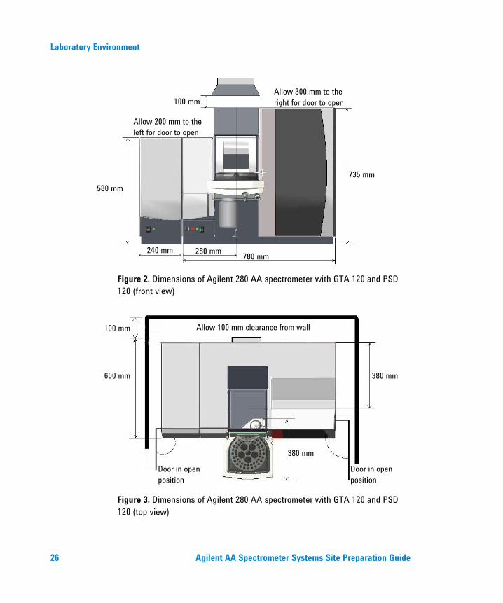
Figure 2. Dimensions of Agilent 280 AA spectrometer with GTA 120 and PSD 120 (front view)
Figure 3. Dimensions of Agilent 280 AA spectrometer with GTA 120 and PSD 120 (top view)
100 mm
600 mm
380 mm
380 mm
Door in open position
Door in open position
Allow 100 mm clearance from wall
Allow 300 mm to the right for door to open 100 mm
Allow 200 mm to the left for door to open
580 mm 735 mm
240 mm 280 mm 780 mm

Laboratory Environment
Agilent AA Spectrometer Systems Site Preparation Guide 27
Figure 4. Dimensions of Agilent 280 AA spectrometer with PSD 120 (side view)
Figure 5. Dimensions of Agilent 240 Series AA spectrometer with GTA 120 and PSD 120 (front view)
735 mm
Allow 100 mm clearance from wall
600 mm
100 mm
240 mm 280 mm 780 mm
735 mm
560
mm
Allow 200 mm to the left for door to open
Allow 300 mm to the right for door to open

Laboratory Environment
28 Agilent AA Spectrometer Systems Site Preparation Guide
Figure 6. Dimensions of Agilent 240 Series AA spectrometer with GTA 120 and PSD 120 (top view)
Figure 7. Dimensions of Agilent 240 Series AA spectrometer with PSD 120 (side view)
100 mm
600 mm
380 mm
380 mm
Door in open position
Door in open position
Allow 100 mm clearance from wall
735 mm
Allow 100 mm clearance from wall
600 mm
Laboratory Environment
Agilent AA Spectrometer Systems Site Preparation Guide 29
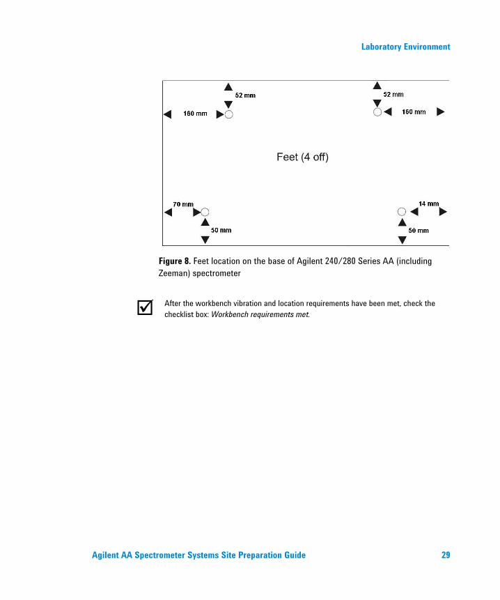
Figure 8. Feet location on the base of Agilent 240/280 Series AA (including Zeeman) spectrometer
After the workbench vibration and location requirements have been met, check the checklist box: Workbench requirements met.

Laboratory Environment
30 Agilent AA Spectrometer Systems Site Preparation Guide
This page is intentionally left blank.

Laboratory Facilities
Agilent AA Spectrometer Systems Site Preparation Guide 31
4. Laboratory Facilities Exhaust System 31 Electrical Power Supplies 33 Gas Supplies 36 Waste Fluids 47 Water Cooling System 49
Exhaust System
Figure 9. Spectrometer and flue position
General The flame operates at a temperature of approximately 3000 °C (5400 °F), and can generate up to 540 kilojoules (510 Btu) per minute. Exhaust fumes can be toxic or corrosive. Under extreme flame conditions, the maximum temperature of the exhaust extraction system (based on the Agilent exhaust system) is 65 °C (149 °F) at a distance of 2.2 m (7.2 ft) above the floor level. However, failure of the extraction fan may cause accessible metalwork to become dangerously hot.
Clamp
Locate the fan at least 3 m (10 ft) away from the flame
100 mm (4 in)
Ducting 150 mm (6 in) diameter
Flue maximum opening 275 mm (11 in)
Chimney
Secure the flue by steel brackets fixed to a wall or suspended from the ceiling by steel rods or chains

Laboratory Facilities
32 Agilent AA Spectrometer Systems Site Preparation Guide
The spectrometer must be located under a flue, which is vented by an exhaust fan and ducted to an external vent. The exhaust system with flue, ducting and external vent must provide a minimum flow of 6 cubic meters per minute (200 cfm) at 16-mm water gauge static pressure (free delivery of 11 cubic meters per minute; or 388 cfm).
The exhaust system installation must comply with any rules and/or regulations that may be imposed by local authorities responsible for control of facilities and fixtures in the workplace.
The exhaust fan should be located at least 3 meters (10 feet) away from the flame. The fan blades must be made of metal. The fan control switch and running indicator lamp should be located close to the instrument.
Ducting must be corrosion-resistant and fire-proof, and should be kept clear of fire alarms, sprinkler heads, heat-sensitive devices and combustible materials. It should rise vertically for at least 2 meters (6 feet) from the spectrometer and there should be no tight bends. All ducting joints must be fitted — the hot exhaust gases may melt soldered joints.
The external vent must be fitted with a backdraft damper, and the outlet location must be clear of doors, windows and air-conditioning inlets.
WARNING
Noxious Gas Any leak can result in an oxygen-deficient atmosphere, which can cause death, serious injury, asphyxiation, anesthetic effects, and serious damage to equipment and property. An exhaust system must be used with Agilent AA flame and furnace instruments, to remove hazardous and toxic gases.
NOTE The Agilent Furnace Fume Extraction System accessory requires an exhaust ducting size of 150 mm (6 in) to fit the mounting plate.

Laboratory Facilities
Agilent AA Spectrometer Systems Site Preparation Guide 33
Agilent exhaust system The components required for an extraction system may be purchased from Agilent either separately or as a kit of parts ready for installation at the instrument site. To allow for personal preferences in the selection of control gear, switch and pilot light assemblies are not included with the items supplied by Agilent.
Table 4. Agilent exhaust kits
Exhaust kit
Exhaust kit for 240 V, 50 Hz supply
Exhaust kit for 115 V, 60 Hz supply
NOTE Mounting hardware for the flue and fan are not included with the Agilent-supplied exhaust kit.
The Agilent-supplied exhaust kit must be installed by local fitters before the Agilent field service engineer is called.
After the exhaust requirements have been met, check the checklist box: Exhaust system is suitable.
Electrical Power Supplies The installation of electrical power supplies must comply with the rules and/or regulations imposed by the local authorities responsible for the use of electrical energy in the workplace.
All Agilent AA instruments are supplied with a 2-meter (6 ft, 6 in) mains power cord terminated as indicated in Table 8.

Laboratory Facilities
34 Agilent AA Spectrometer Systems Site Preparation Guide
All power supplies should be single phase AC, 3-wire system (active, neutral and ground, or two actives and ground) and should be terminated at an appropriate connection receptacle that is within reach of the system power cable assembly. In areas where 208/220/240 volt supplies are not normally available in a single phase configuration, supplies may be taken from two phases and ground of a three phase system.
A separate connection receptacle should be provided for each unit in the system (see Table 7). Do not use double adapters or extension cords.
A separate mains circuit individually protected by fuses or circuit breakers must be used for the GTA accessory. It is preferable for the GTA and the instrument to share the same phase.
NOTE If the system being installed is a Zeeman system, then two separate mains circuits individually protected by fuses or circuit breakers must be used — one each for the instrument and the Zeeman GTA accessory. It is preferable for the GTA and the instrument to share the same phase but separate power supply circuits.
Avoid using power supplies from a source that may be subject to electrical interference from other services (large electric motors, elevators, welders and air conditioning units, and so forth).
Table 5. Electrical specifications for Agilent AA systems
System unit Required supply voltage Rating
55B AA spectrometer 100, 120, 220 or 240 VAC, 50/60 Hz 170 VA
240 AA spectrometer 100, 120, 220 or 240 VAC, 50/60 Hz 170 VA
280 AA spectrometer 100, 120, 220 or 240 VAC, 50/60 Hz 230 VA
240 Z AA spectrometer 208-240 VAC, 50/60 Hz 1000 VA*
280 Z AA spectrometer 208-240 VAC, 50/60 Hz 1000 VA*
GTA Graphite Tube Atomizer (GTA 120) 208/220/240 VAC, 50/60 Hz 15 A*
SIPS 10/20 Sample Introduction Pump System 100-240 VAC 70 W
Laboratory Facilities
Agilent AA Spectrometer Systems Site Preparation Guide 35
System unit Required supply voltage Rating
SPS 4 Autosampler 100-240 VAC, 50/60 Hz 24 VDC, 2.5 A
VGA 77 Vapor Generation Accessory 100, 120, 220 or 240 VAC, 50/60 Hz 20 VA
ETC 60 Electrothermal Temperature Controller 110-120, 220-240 VAC, 50/60 Hz 755 VA maximum
UltrAA Boosted Lamp Supply 100, 120, 220 or 240 VAC, 50/60 Hz 150 VA
* In normal operation, the Zeeman and GTA units will draw surge currents in excess of the nominal rating. Power supplies to these units must be isolated from other supplies to the system, and should include delayed action protection devices such as circuit breakers or motor start fuses.
The VA and current figures above are the typical continuous VA and current drawn by AA and GTA. During the atomize cycle, surge currents for very short spans of time (between 1 and 5 second) may be drawn by AA (up to 48 A) and by GTA (up to 40 A).
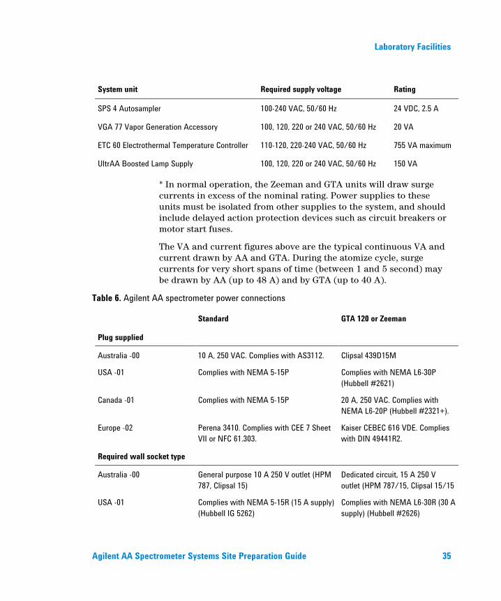
Table 6. Agilent AA spectrometer power connections
Standard GTA 120 or Zeeman
Plug supplied
Australia -00 10 A, 250 VAC. Complies with AS3112. Clipsal 439D15M
USA -01 Complies with NEMA 5-15P Complies with NEMA L6-30P (Hubbell #2621)
Canada -01 Complies with NEMA 5-15P 20 A, 250 VAC. Complies with NEMA L6-20P (Hubbell #2321+).
Europe -02 Perena 3410. Complies with CEE 7 Sheet VII or NFC 61.303.
Kaiser CEBEC 616 VDE. Complies with DIN 49441R2.
Required wall socket type
Australia -00 General purpose 10 A 250 V outlet (HPM 787, Clipsal 15)
Dedicated circuit, 15 A 250 V outlet (HPM 787/15, Clipsal 15/15
USA -01 Complies with NEMA 5-15R (15 A supply) (Hubbell IG 5262)
Complies with NEMA L6-30R (30 A supply) (Hubbell #2626)

Laboratory Facilities
36 Agilent AA Spectrometer Systems Site Preparation Guide
Canada -01 Complies with NEMA 5-15R (15 A supply) (Hubbell IG 5262)
20 A, 250 VAC. Complies with NEMA L6-20R (Hubbell #2326+)
Europe -02 Complies with CEE 7 standard No.7 Sheet VII, or Norma Francais C61.303 Sheet V.A.
No standard known (Kaiser CEBEC 702 type 31/131.5)
Power supply, current rating and overload protection
Between 5 and 20 A Between 30 and 40 A
Power supply Single phase Single phase
After the electrical requirements have been met, check the checklist box: Specified electrical supply and power outlets installed.
Gas Supplies All gas supply installations must comply with rules and/or regulations that are imposed by the local authorities responsible for the use of compressed gas energy in the workplace. The following points should be considered.
Pressure cylinder storage Cylinders containing gas under pressure should be firmly secured to a rigid structure, and the storage area must be adequately ventilated. Acetylene cylinders should always be stored and moved in an upright position to avoid acetone saturation of the fibrous safety disc and acetone contamination of the acetylene flow. Acetone contamination will cause erratic analytical results and may damage the instrument. Such damage is not covered by the instrument warranty.
Never locate gas cylinders near a source of ignition, or in a position that is subject to direct heat. Gas storage cylinders often incorporate a pressure release device, which will discharge the gas at a pre-determined temperature, usually around 52 °C (125 °F). See Figure 14.
Laboratory Facilities
Agilent AA Spectrometer Systems Site Preparation Guide 37
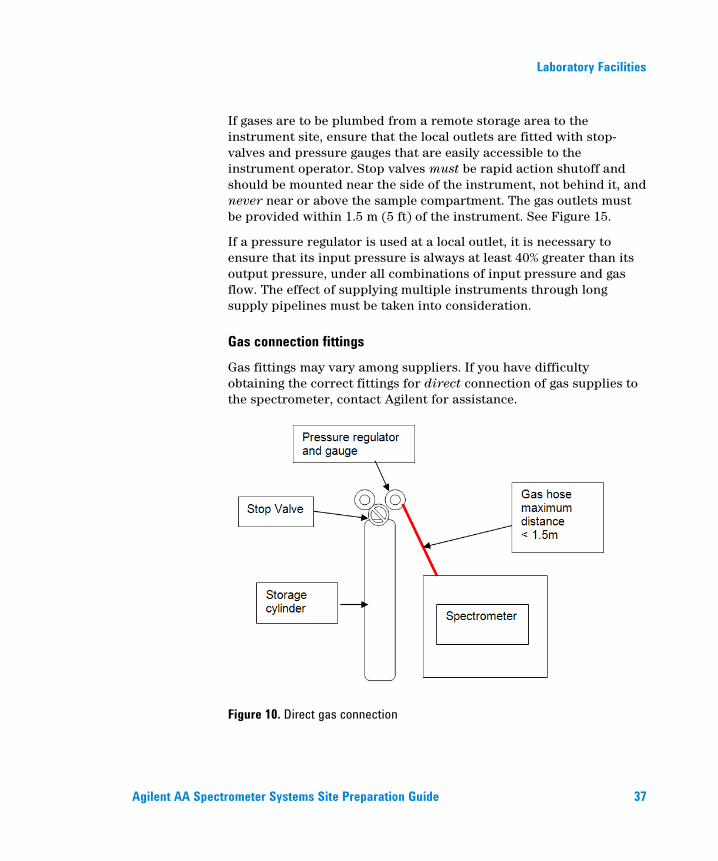
If gases are to be plumbed from a remote storage area to the instrument site, ensure that the local outlets are fitted with stop-valves and pressure gauges that are easily accessible to the instrument operator. Stop valves must be rapid action shutoff and should be mounted near the side of the instrument, not behind it, and never near or above the sample compartment. The gas outlets must be provided within 1.5 m (5 ft) of the instrument. See Figure 15.
If a pressure regulator is used at a local outlet, it is necessary to ensure that its input pressure is always at least 40% greater than its output pressure, under all combinations of input pressure and gas flow. The effect of supplying multiple instruments through long supply pipelines must be taken into consideration.
Gas connection fittings Gas fittings may vary among suppliers. If you have difficulty obtaining the correct fittings for direct connection of gas supplies to the spectrometer, contact Agilent for assistance.
Figure 10. Direct gas connection

Laboratory Facilities
38 Agilent AA Spectrometer Systems Site Preparation Guide
Figure 11. Remote storage location gas connection
Permitted gas supplies Only three gases are specified for use in a flame instrument. They are air, nitrous oxide and acetylene. Agilent will not install a flame instrument where other gases may be provided for connection to it. The GTA accessory requires an inert gas (argon or nitrogen), and can use air or other gases as an alternate gas, but does not use nitrous oxide and acetylene.
In planning your gas reticulation scheme, observe the following points:
Never run rubber tubing through a wall or across a floor.
Never use rubber tubing outdoors.
Acetylene tubing must be stainless steel or black iron.
Use only refrigeration-grade copper pipe for other gases — plumbing-grade has oil and grease residues.
Do not cut off the factory-fitted hose connectors. These are needed to connect to test equipment gas-handling jigs. Their removal will cause extra expense during service calls.
Use only 3/8-in tube or 1/2-in pipe to minimize pressure drop.
Laboratory Facilities
Agilent AA Spectrometer Systems Site Preparation Guide 39
Fit pressure gauges on a wall at the supply point, and ensure that they are visible to the operator.
Place cutoff valves in a position that can be reached safely in case of a fire.
WARNING
Fire and Explosion Hazard Fire and/or explosion hazard, which could result in death or serious injury to personnel and damage to property. Agilent AA instruments are designed for flame operation only with acetylene and air, or acetylene and nitrous oxide. The use of unspecified gases for flame operation of the spectrometer is extremely hazardous. Use only the specified gases, and ensure that the installation complies with the relevant rules and regulations as laid down by the appropriate authorities in your region.
Gas line diameter All gases should be supplied through gas lines with an internal diameter no smaller than 6.4 mm (1/4 in).
Air supply
Table 7. Air supply specifications
Parameter Specification Quality Clean, dry, free of oil Permissible pressure range 245 to 455 kPa (35 to 65 psi) Recommended pressure 350 kPa (50 psi) Normal flow rate 13.5 to 20 L/min

Laboratory Facilities
40 Agilent AA Spectrometer Systems Site Preparation Guide
WARNING
Fire and Explosion Hazard Fire and/or explosion hazard, which could result in death or serious injury to personnel and damage to property. Air enriched with oxygen, or pure oxygen, must never be used with a flame instrument, as it will cause a flashback.
The instrument air hose is fitted with a US Standard Compressed Air Connection, Female Union, Size 9/16 in - 18 UNF. The hose is 1.8 m (6 ft) long. Connection adapters are supplied to suit different locations, as illustrated in Figure 16.
The air supply must be regulated to maintain the instrument operating pressure over the full range of normal flow rates. A dual-stage regulator should be used. This is most important for instruments with programmable flow rates because a slow response from the regulator may cause the instrument to shut down during a demand for increased flow. A shutdown of this kind is safe and does not imply a fault in the instrument, but will interrupt your work.
If you choose to use an air compressor, it must be installed in a remote location where its intake is fed from a dry, dust and vapor-free environment. The control switch and pilot light should be mounted close to the instrument.
Where the air supply is derived from a general purpose in-house system or from a dedicated air compressor, a filter unit must be installed. If your location has high humidity, the air supply should include a dryer or condenser device.
Laboratory Facilities
Agilent AA Spectrometer Systems Site Preparation Guide 41
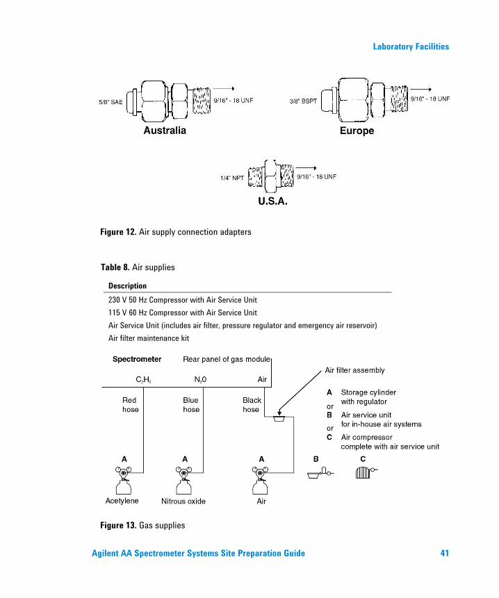
Figure 12. Air supply connection adapters
Table 8. Air supplies
Description 230 V 50 Hz Compressor with Air Service Unit 115 V 60 Hz Compressor with Air Service Unit Air Service Unit (includes air filter, pressure regulator and emergency air reservoir) Air filter maintenance kit
Figure 13. Gas supplies
Laboratory Facilities
42 Agilent AA Spectrometer Systems Site Preparation Guide
Nitrous oxide supply
Table 9. Nitrous oxide supply specifications
Parameter Specification Quality Instrument-grade, 99.5% pure (minimum) Permissible pressure range 245 to 455 kPa (35 to 65 psi) Recommended pressure 350 kPa (50 psi) Normal flow rate 11 to 16 L/min
NOTE Instrument-grade nitrous oxide must be used. If you choose to use industrial-grade, instrument performance is not guaranteed.
The instrument nitrous oxide hose is fitted with a US Standard Nitrous Oxide Gas Connection, Female Union, Size 3/4 in - 16 UNF. The hose is 1.8 m (6 ft) long. Connection adapters are supplied to suit different locations as illustrated in Figure 18.
The nitrous oxide supply must be regulated to maintain the instrument operating pressure over the full range of normal flow rates. A dual-stage regulator should be used. This is most important for instruments with programmable flow rates because a slow response from the regulator may cause the instrument to shut down during a demand for increased flow. A shutdown of this kind is safe and does not imply a fault in the instrument, but will interrupt your work.
Nitrous oxide is stored as a liquid. Evaporation across the regulator may cause it to freeze at high flow rates. This can cause erratic flame conditions and in extreme cases, may cause a flashback. You can purchase a pre-heater, which will prevent freezing. Your Agilent sales and service office can advise you and can supply these devices:
Table 10. Nitrous oxide supplies
Region Description North America Regulator with integral thermostatted heater Continental Europe Heater, for connection between cylinder and regulator

Laboratory Facilities
Agilent AA Spectrometer Systems Site Preparation Guide 43
Figure 14. Nitrous oxide supply connection adapters

Laboratory Facilities
44 Agilent AA Spectrometer Systems Site Preparation Guide
Acetylene supply
Table 11. Acetylene supply specifications
Parameter Specification Quality Instrument-grade, 99.0% pure (minimum) Permissible pressure range 65 to 100 kPa (9.5 to 14.5 psi) Recommended pressure 75 kPa (11 psi) Normal flow rate 0 to 10 L/min Packaging solvent Acetone
Figure 15. Acetylene supply connection adapters
The instrument acetylene hose is fitted with a US Standard Acetylene Gas Connection, Female Union, Size 9/16 in - 18 UNF, left thread. The hose is 1.8 m (6 ft) long. Connection adapters are supplied to suit different locations as illustrated in Figure 19.
The acetylene supply must be regulated to maintain the instrument operating pressure over the full range of normal flow rates. A dual stage regulator should be used. This is most important for instruments with programmable flow rates because a slow response from the regulator may cause the instrument to shut down during a demand for increased flow. A shutdown of this kind is safe and does not imply a fault in the instrument, but will interrupt your work.

Laboratory Facilities
Agilent AA Spectrometer Systems Site Preparation Guide 45
Acetone, the acetylene packaging solvent, can damage neoprene, rubber and plastic components of the instrument. It can also absorb ultraviolet light and may affect analytical performance. High levels of acetone will reduce the flame temperature, which may affect analytical results at many wavelengths. Acetone may be entrained in the acetylene gas at low cylinder pressure.
NOTE You must replace the cylinder when its pressure falls to 700 kPa (100 psi) to prevent acetone from being entrained in the acetylene gas and causing damage to the instrument. Acetone may also be entrained if the flow rate exceeds 1/7th of the cylinder contents per hour. Your supplier can advise you on an appropriately rated cylinder.
Instrument-grade acetylene is free of phosphorus, arsenic and sulfur contaminants, which are residues of the acetylene generation process (calcium carbide and water). Phosphine content is also minimized. Phosphine contamination will depress calcium, strontium and barium absorption signals. Broadband emission from phosphine combustion products can interfere with sodium and potassium analysis.
Acetylene is unstable as a free gas under pressure and it should not be piped at pressures exceeding 105 kPa (15 psi). Explosive acetylides can form if acetylene contacts unalloyed copper, silver or mercury.
WARNING
Fire and Explosion Hazard Fire and/or explosion hazard, which could result in death or serious injury to personnel and damage to property. Never use copper tubing or tubing of alloys with more than 65% copper content. With these materials, copper acetylide could be formed and there is the risk of spontaneous fire or explosion. Always use stainless steel, or black iron pipe for fixed supply lines, and test for leaks at regular intervals. The installation of acetylene gas must comply with the rules and regulations of the relevant local, state and federal authorities.

Laboratory Facilities
46 Agilent AA Spectrometer Systems Site Preparation Guide
Gas supplies for Graphite Tube Atomizers (Zeeman and non-Zeeman) Argon, nitrogen and air are the only gases recommended for use with an Agilent GTA. Proprietary mixtures of argon or nitrogen containing up to 5% hydrogen may be used. If your applications require other gases, contact your Agilent sales and service office.
Table 12. GTA gas supply specifications
Parameter Specification Normal gas inlet quality High purity argon, 99.99% pure (minimum)
High purity nitrogen, 99.99% pure (minimum) Alternate gas inlet quality High purity nitrogen, 99.99% pure (minimum)
Air, clean, dry and free of oil Recommended pressure range
140 to 200 kPa (20 to 30 psi)
Maximum pressure 350 kPa (50 psi) Normal flow rate (GTA 120) 0 to 0.3 L/min for internal flow, plus separate
external flow of 0.5 L/min. Additional Boost flow of 3.0 L/min during atomization when programmed temperature exceeds 400 °C.
The GTA control unit is fitted with standard barbed-tail adapters for connection of gas supplies using reinforced plastic tubing (supplied) of 6 mm (1/4 in) internal diameter.
GTA gas supplies must be regulated to maintain the accessory operating pressures over the full range of normal flow rates under dynamic conditions. Dual-stage regulators should be used.
Gas supplies for the Vapor Generation Accessory Argon and nitrogen are the only gases recommended for use with the Agilent VGA. If your applications require other gases, contact your Agilent sales and service office.

Laboratory Facilities
Agilent AA Spectrometer Systems Site Preparation Guide 47
Table 13. VGA gas supply specifications
Parameter Specification Quality High purity argon, 99.99% pure (minimum) or
High purity nitrogen, 99.99% pure (minimum) Permissible pressure range 300 to 400 kPa (43 to 57 psi) Recommended pressure 300 kPa (43 psi) Normal flow rate 0.05 to 0.1 L/min
The VGA is fitted with 6-mm (1/4-in) internal diameter reinforced plastic hose for connection to a standard 6-mm (1/4-in) barbed-tail connector.
VGA gas supplies must be regulated to maintain the accessory operating pressure at its normal flow rate.
The VGA gas outlet should be fitted with a shutoff valve to prevent the loss of approximately 50 mm per minute of inert gas, which continues to flow when the VGA power is turned off.
After the gas requirements have been met, check the checklist box: All gas supplies (at specified purities), regulators, and gas lines are installed.
Waste Fluids The Agilent AA flame instrument atomizes only a small percentage of the sample taken up. The excess liquids from the spray chamber must be drained into a waste vessel. Suitable tubing is supplied with the spectrometer for use with inorganic solvents. If you use organic solvents, you will need different tubing, suitable for the solvent(s) of choice.
The Agilent AA instrument also needs a drain or a sump for disposal of waste liquid during rinse cycles when flame or furnace autosamplers are used.
A chemically-inert container, not glass and not narrow-necked, to hold approximately 2 liters (4 pints) of waste must be provided by the instrument user. It should be located underneath the sample compartment (or on the side to the right of the spectrometer), where it is protected by the bench and in full view of the operator.
Laboratory Facilities
48 Agilent AA Spectrometer Systems Site Preparation Guide
Special arrangements for use with organic solvents If organic solvents are used in a flame system, the following special option fittings are recommended.
Table 14. Optional fittings for organic solvent waste fluids
Item Kit, O-rings (Organics) Tube, butyl, 9 mm ID, 15 mm OD (1 m length)
A suitable outlet for the liquid trap vent pipe must also be provided. A venting tube should be connected to the vapor vent (the upper nipple) on the liquid trap when you are analyzing organic or toxic liquids. This tubing should be led out from the sample compartment, parallel to the drain tubing, and must slope downwards to enable any liquid overflow to drain out and prevent the tubing from becoming blocked. Do not lead the vapor tube to the waste vessel.
Note the following:
The venting tube cannot be routed upwards within the sample compartment, because the heat from the flame will melt it.
If organic vapors are vented to the exhaust system, they may be ignited by the flame and so cause damage to the exhaust system.
Local environmental protection laws may prohibit toxic vapors from being discharged in to the general atmosphere or into a working area.
If necessary, an active exhaust system should be used to draw away toxic vapors and neutralize them. If you are not analyzing solutions of an organic or toxic nature, leave the vapor outlet on the spray chamber uncovered.
After the waste fluid container requirements have been met, check the checklist box: Waste container appropriate for the chemical waste is prepared.
Laboratory Facilities
Agilent AA Spectrometer Systems Site Preparation Guide 49
Water Cooling System The Graphite Tube Atomizer must have a supply of cooling water to remove heat from the furnace workhead.
Table 15. GTA water cooling system specifications
Parameter Specification Required flow rate 1.5 L/min at 180 kPa (27 psi) Maximum pressure 200 kPa (30 psi) Recommended inlet temperature 18 to 25 °C (64 to 70 °F) Maximum temperature 40 °C (104 °F) Minimum temperature 10 °C (50 °F)
A suitable regulator is included in the GTA 120 control unit. It will be adjusted, if necessary, by the customer support representative. Pressure regulation is recommended for supplies that may exceed the maximum permissible pressure.
The temperature of the furnace coolant is detected by an interlock device, which will stop operation if the cooling water reaches 40 degrees Celsius (104 °F). Where the ambient temperature is high or where a low-capacity water cooling system is used, you may need to include some form of heat exchanger to maintain the recommended water inlet temperature.
Provided that the flow rate can be maintained above 1.5 liters per minute and there is no backpressure at the outlet, the cooling water supply may be taken from an in-house domestic water system, if local regulations permit.
An alternative is to install a small recirculating system, which should have a tank capacity of at least 100 liters (27 gallons). The tank should be covered to prevent contamination by dust and other impurities and to minimize evaporation loss. Algicide should be used. A heat exchanger may be necessary. Any such installation must be capable of extracting 950 W at 20 °C de-rated by 17% for 50 Hz operation.
A refrigerated water cooler has the advantage of not needing a large held volume of water. There are many types available. When choosing a water cooler, check that the specifications meet the requirements of the GTA.
Laboratory Facilities
50 Agilent AA Spectrometer Systems Site Preparation Guide
Your local Agilent office or representative may be able to supply a suitable refrigerated water cooler for use with the Agilent GTA. Contact your local office or representative for details if required.
After the water cooling requirements have been met, enter the requested information and then check the checklist box: Water cooling/circulation system and power connections are set up.

Instrument Shipping Information
Agilent AA Spectrometer Systems Site Preparation Guide 51
5. Instrument Shipping Information Insurance After Delivery 51 Transit Damage 52 In-House Transit Routes 53
Insurance After Delivery As the carrier’s liability ceases when the equipment is delivered, Agilent recommends that you arrange separate insurance that will cover transportation from the delivery point to the installation site. The delivery point will vary according to the carrier, the shipping method, and in some cases the terms of sale. Some carriers will only deliver to their own distribution center, while others may deliver to your off-loading bay. Few will deliver to the actual installation site.

Instrument Shipping Information
52 Agilent AA Spectrometer Systems Site Preparation Guide
Transit Damage Transit damage can be obvious or concealed, and in either case will only be admitted by the carrier if it is reported as agreed in the terms of the carrier's agreement. For any claims against damage in transit, the following general rules apply:
1 Before accepting delivery, you should inspect the packages for signs of obvious damage. The nature of any obvious damage must be noted on the carrier’s way-bill, and then must be countersigned by a representative of the carrier.
2 Within the time limits stated in the terms of conditions of carriage, a further inspection must be made for concealed damage. If any damage is found at this stage, the carrier must be notified in writing and all packaging material must be retained for subsequent inspection by a representative of the carrier.
3 A copy of any damage report must be forwarded to the Agilent sales office dealing with the supply of the equipment.
Agilent instruments are inherently robust, and the packaging is designed to prevent internal damage when shipped or handled in accordance with the labels and warnings. However, it must be remembered that the contents form part of a precision measuring system, and all packages should be handled accordingly. In transit, sharp jolts and shocks must be avoided, and the packages must not be unnecessarily inverted or tilted. Markings on the shipping cartons generally indicate which side of the package should be kept at the top.
WARNING
Heavy Weight Many of the packages are large and heavy. To avoid injury to personnel, or accidental damage to the equipment, always use two or more people when lifting equipment into position. Never attempt to lift packages alone.

Instrument Shipping Information
Agilent AA Spectrometer Systems Site Preparation Guide 53
WARNING
Shock Hazard To prevent death or personnel injury from accidental contact with high voltages within the instrument, do not remove any of the instrument covers. Do not connect the instrument to the mains supply.
In-House Transit Routes In-house transit routes must be carefully considered. Vertical, horizontal and turning clearances should be calculated from the shipping crate dimensions of the spectrometer, which is the largest unit in any system arrangement.
Figure 20 provides an indication of the minimum turning clearance and minimum door width required for the spectrometer in its shipping crate.
Particular attention should be made to the clearance of any doors in the transit route to the laboratory. The required turning and door clearance may need to take into consideration any lifting device used for transporting the instrument (for example, fork lift, pallet truck or trolley).
Figure 16. Minimum clearance required for transportation in the shipping crate (Agilent 55B/240/280 AA)
Minimum door dimension
1200 mm (47.2 in)
Minimum turning dimension
1450 mm (57.1 in)
Instrument Shipping Information
54 Agilent AA Spectrometer Systems Site Preparation Guide
Carefully check the clearance of any doors in the transit route to the laboratory. The required turning and door clearance may need to take into consideration any lifting device used for transporting the instrument (for example, fork lift, pallet truck or trolley).
After the in-house transit route requirements have been met, check the checklist box: Entrance to the lab is at least 1450 cm (57.1 in) wide.
After the instrument is unpacked and on the bench top, check the checklist box: Instrument unpacked and placed on the workbench.

Software Installation Guidelines
Agilent AA Spectrometer Systems Site Preparation Guide 55
6. Software Installation Guidelines Installing the Microsoft Windows Operating System 55 Installing Agilent SpectrAA Software 56 Installing Agilent SpectrAA CFR Software 56
The following information assumes that you are working on a clean, empty hard disk. If you have any other files on the PC hard disk, ensure you make backups of these before continuing.
NOTE Agilent will not assume responsibility for loss of data.
Installing the Microsoft Windows Operating System For instructions on installing the Microsoft Windows operating system, refer to the Microsoft Windows manuals supplied with the software. If the customer is supplying the PC, it is their responsibility to ensure Microsoft Windows 7 Professional 64-bit SP1 or Windows 10 Professional 64-bit is installed. In addition, if you are providing your own PC with a Windows 10 operating system you must ensure Microsoft .NET Framework 3.5 is installed before installing the SpectrAA software.
SpectrAA Base (for use with SpectrAA Base version 5.4 or greater)
SpectrAA PRO (for use with SpectrAA PRO version 5.4 or greater)
SpectrAA CFR (for use with SpectrAA CFR version 5.4 or greater)

Software Installation Guidelines
56 Agilent AA Spectrometer Systems Site Preparation Guide
NOTE To ensure correct operation, the user installing the operating system must have Administrator privileges for correct installation of Agilent AA software.
Installing Agilent SpectrAA Software For instructions on installing Agilent AA software, refer to the software installation instructions that came with your software.
Installing Agilent SpectrAA CFR Software Agilent SpectrAA CFR software should be installed by the System Administrator and the System Administrator must be onsite during installation of the Agilent AA instrument.
NOTE Agilent SpectrAA CFR software requires either SpectrAA Base or Pro software to be installed prior to installation.
Refer to the ‘21 CFR Part 11 Electronic Records, Electronic Signatures Compliance’ manual, the SDA Help and the SCM Help supplied with the SpectrAA CFR software for details on how to configure the Microsoft Windows operating system and for details on setting up users and assigning user privileges.

Operator Training
Agilent AA Spectrometer Systems Site Preparation Guide 57
7. Operator Training
Operator confidence when using atomic absorption instrumentation is essential to obtain accurate and reliable results. The Agilent field service engineer who installs your equipment will demonstrate the basic operating procedures while conducting the installation performance tests. The engineer is not necessarily experienced in more complex analytical procedures and is not authorized to conduct extended training. The service representative will explain elementary operations but is not authorized to conduct extended training on the Microsoft Windows operating system.
Your operators will gain most from observing the installation and will be more immediately productive if they have already been trained. Agilent recommends that you take advantage of special training courses that are conducted at various locations by the Agilent technical support organization.
In some locations, it may be possible to arrange for operator training after the installation, using your own instrument. Contact your Agilent sales and service office if you would like to arrange this.
Operator Training
58 Agilent AA Spectrometer Systems Site Preparation Guide
This page is intentionally left blank.

www.agilent.com
In This Guide The guide describes the following:
Safety Practices and Hazards
Introduction
Laboratory Environment
Laboratory Facilities
Instrument Shipping Information
Software Installation Guidelines
Operator Training
© Agilent Technologies 1994, 1995, 1997, 1998, 2000–2003, 2007, 2010 and 2012-2013, 2016, 2017 02/17
*8510119300* *8510119300*
8510119300 Issue 16