
Agilent 55B AA Spectrometer
138
Agilent 55B AA Spectrometer User’s Guide
Transcript of Agilent 55B AA Spectrometer

Agilent 55B AA Spectrometer
User’s Guide

2 Agilent 55B AA Spectrometer User’s Guide
Notices © Agilent Technologies, Inc. 1997, 2000, 2002, 2009, 2010, 2012 and 2013, 2016, 2017
No part of this manual may be reproduced in any form or by any means (including electronic storage and retrieval or translation into a foreign language) without prior agreement and written consent from Agilent Technologies, Inc. as governed by United States and international copyright laws.
Manual Part Number 8510154100
Edition Twelth edition, December 2017
Printed in Malaysia
Agilent Technologies Australia [M] Pty Ltd
679 Springvale Road
Mulgrave, Victoria 3170, Australia
www.agilent.com
Warranty The material contained in this document is provided “as is,” and is subject to being changed, without notice, in future editions. Further, to the maximum extent permitted by applicable law, Agilent disclaims all warranties, either express or implied, with regard to this manual and any information contained herein, including but not limited to the implied warranties of merchantability and fitness for a particular purpose. Agilent shall not be liable for errors or for incidental or consequential damages in connection with the furnishing, use, or performance of this document or of any information contained herein. Should Agilent and the user have a separate written agreement with warranty terms covering the material in this document that conflict with these terms, the warranty terms in the separate agreement shall control.
Technology Licenses The hardware and/or software described in this document are furnished under a license and may be used or copied only in accordance with the terms of such license.
Restricted Rights Legend If software is for use in the performance of a U.S. Government prime contract or subcontract, Software is delivered and licensed as “Commercial computer software” as defined in DFAR 252.227-7014 (June 1995), or as a “commercial item” as defined in FAR 2.101(a) or as “Restricted computer software” as defined in FAR 52.227-19 (June 1987) or any equivalent agency regulation or
contract clause. Use, duplication or disclosure of Software is subject to Agilent Technologies’ standard commercial license terms, and non-DOD Departments and Agencies of the U.S. Government will receive no greater than Restricted Rights as defined in FAR 52.227-19(c)(1-2) (June 1987). U.S. Government users will receive no greater than Limited Rights as defined in FAR 52.227-14 (June 1987) or DFAR 252.227-7015 (b)(2) (November 1995), as applicable in any technical data.
Safety Notices
A CAUTION notice denotes a hazard. It calls attention to an operating procedure, practice, or the like that, if not correctly performed or adhered to, could result in damage to the product or loss of important data. Do not proceed beyond a CAUTION notice until the indicated conditions are fully understood and met.
A WARNING notice denotes a hazard. It calls attention to an operating procedure, practice, or the like that, if not correctly performed or adhered to, could result in personal injury or death. Do not proceed beyond a WARNING notice until the indicated conditions are fully understood and met.
WARNING
CAUTION

Contents
Agilent 55B AA Spectrometer User’s Guide 3
Contents
1. Safety Practices and Hazards 11
Verifying Safe State 12
Electrical Hazards 12
Heat, Vapors and Fumes 13
Compressed Gases and Cylinders 14
Gas Hoses and Connections 15
Ultraviolet Radiation 16
Other 16
Warning Symbols 16
CE Compliance 18
Electromagnetic Compatibility 19
EN55011/CISPR11 19 ICES/NMB-001 20
Flame Operation 20
Flammable Solvents 20 Compressed Gases and Cylinders 22 Acetylene 22 Nitrous Oxide 24 Burners 24 Nebulizer 25 Liquid Trap 26 Heat Hazards 26 Perchloric Acid 27

Contents
4 Agilent 55B AA Spectrometer User’s Guide
Flashbacks 28
2. Introduction 31
Site Preparation Requirements 32
Documentation 32
Conventions 32
Specifications 33
Environmental Specifications 33 Gas Supplies 34
3. Installation 35
Instrument Overview 36 Connections 37 Power 38 Moving Your Instrument 39
Lamp Compartment 39
Hollow Cathode Lamps 40 D2 Lamp 41
Sample Compartment 42
Nebulizer 42 Spraychamber 45 Burner 54 Sample Compartment Front Panel 55 Flame Shield 56
4. Interface 57
Introduction 57 Display 58

Contents
Agilent 55B AA Spectrometer User’s Guide 5
Keypad 61
Agilent 55B AA Pages 63 Load Method Page 63 Instrument Parameters Page 63 Measurement Parameters Page 65 Options Page 66 Optimization Page 69 Calibration Parameters Page 69 Results Page 70
Navigating the Interface 71
Changing Pages 71 Selecting Menus 71 Moving Between Fields 72
5. Operation 75
Pre-Analysis Checklist 75
Starting the System 76
Method Development 77 Selecting the Language of the Interface 77 Loading a Method 77 Setting the Instrument Parameters 78 Setting the Measurement Parameters 79 Defining the Calibration Standards 79 Saving/Deleting Methods 80
Optimization 81 Aligning Lamps 81 Aligning the Burner 83 Lighting the Flame 83

Contents
6 Agilent 55B AA Spectrometer User’s Guide
Optimizing the Flame Signal 85
Nebulizer Setup 86 High Vacuum Setting 86 Low Vacuum Setting 87 Setting Zero Uptake Rate 87 Setting the Uptake Rate for Organic Solvents 88 Performance Checks 88
Calibrating the Method 89 Measuring Standards Manually 89 Measuring Standards Using SIPS 10 90 Displaying the Calibration Graph 90 Resloping the Calibration 91
Sample Measurement 92
Measuring Samples Manually 92 Measuring Samples with SIPS 92
Results 93
Printing the Results 93 Output to LIMS System 93
Shutting Down the System 94
6. Maintenance 95
Maintenance Schedule 95 Daily 95 Weekly 96 Yearly 96
Cleaning 96 General 96

Contents
Agilent 55B AA Spectrometer User’s Guide 7
Windows 96 Filters 97
Burners 97 Cleaning the Burner 97
Nebulizer 99 Routine maintenance 99 Removing the Nebulizer Block 100 Disassembling the Nebulizer 101 Cleaning a Blocked Nebulizer 102 Reassembling the Nebulizer 103
Impact Bead 104 Removing the Impact Bead 104 Installing and Adjusting the Impact Bead 107
Spraychamber 108 Disassembling the Spraychamber 108 Cleaning the Spraychamber 108
Gas Supplies 109
D2 Lamp 109
Fuses 111
7. Spare Parts 115
Sample Introduction 115 Other 118 Covers/Doors 118 Fuses 118 Miscellaneous 118

Contents
8 Agilent 55B AA Spectrometer User’s Guide
8. Troubleshooting/Errors 119
Common Problems 119
Error Messages 122
0804 LIMS port error 122 2851 SIPS comms error 122 3800 EEPROM storage error 123 5004 Signals not increasing 123 5005 Slope test failure 123 5006 Calibration fit failure 123 5008 Reslope signal out of range 123 6000 Check HC lamp selection 124 9159 EEPROM checksum zero wl 124 9160 EEPROM checksum mono correction 124 9307 RBC/Mains frequency below 48Hz. 124 9308 RBC/Mains frequency 124 9309 RBC/Mains frequency above 62Hz 125 9310 Optical RBC frequency 125 9311 Instrument Fault +12V PSU 125 9312 Instrument Fault -12V PSU 125 9313 Instrument Fault 5V PSU 125 9316 Wavelength out of range 126 9317 No Peak: Low HC Lamp Energy 126 9318 No Peak: High HC Lamp Energy 126 9319 No Peak: Low BC Lamp Energy 127 9320 No Peak: High BC Lamp Energy 127 9321 No Peak: Low HC Lamp Energy 127 9322 No Peak: High HC Lamp Energy 128 9323 Low Emission: No Peak 128 9324 High Emission: No Peak 128 9329 No Peak detected 129 9330 No Peak detected 129

Contents
Agilent 55B AA Spectrometer User’s Guide 9
9337 Instrument Fault 310V PSU 130 9339 Mono resetting. Please wait 130 9415 Instrument Fault: Lamp code 130 9422 Instrument Fault: Lamp current 130 9514 Instrument Signal saturation 131 9517 Low HC Lamp Energy 131 9518 High HC Lamp Energy 131 9524 Low BC Lamp Energy 132 9525 High BC Lamp Energy 132 9527 Instrument Fault: EHT failed 132 9528 Background Lamp failed 132 9529 Background Lamp interlock 133 9530 Instrument Fault: Signal diagnostics 133 9531 No Lamp Current detected 133 9602 Instrument Fault: Mono Datum 133 9911 No Burner Fitted 133 9912 N2O Burner not fitted 134 9914 No Gas Control Unit 134 9915 Flame Shield Open 134 9916 Fault: Gas pressure sensor 134 9917 No Oxidant gas pressure 134 9920 Fault: Flame detected 135 9921 Flame Out Detected 135 9922 Flame Shutdown: Gas type 135 9923 Flame Ignition Timeout 135 9934 Flame Shutdown: host offline 136 9937 Flame Pressure Relief Bung 136 9938 Liquid Trap Not Ready 136 9xxx GPIB Fault 136 9xxx Instrument Error 136 9xxx SpectrAA Error 136

Contents
10 Agilent 55B AA Spectrometer User’s Guide
This page is intentionally left blank.

Safety Practices and Hazards
Agilent 55B AA Spectrometer User’s Guide 11
1. Safety Practices and Hazards Verifying Safe State 12 Electrical Hazards 12 Heat, Vapors and Fumes 13 Compressed Gases and Cylinders 14 Gas Hoses and Connections 15 Ultraviolet Radiation 16 Other 16 Warning Symbols 16 CE Compliance 18 Electromagnetic Compatibility 19 Flame Operation 20 Flammable Solvents 20 Compressed Gases and Cylinders 22 Acetylene 22 Nitrous Oxide 24 Burners 24 Nebulizer 25 Liquid Trap 26 Heat Hazards 26 Perchloric Acid 27 Flashbacks 28
Your Agilent 55B AA instrument and accessories have been carefully designed so that when used properly you have an accurate, fast, flexible and safe analytical system.

Safety Practices and Hazards
12 Agilent 55B AA Spectrometer User’s Guide
If the equipment is used in a manner not specified by the manufacturer, the protection provided by the equipment may be impaired.
Operation of an atomic absorption spectrometer can involve the use of compressed gases, flames, and hazardous materials including corrosive fluids and flammable liquids. Unskilled, improper, or careless use of this instrument can create explosion hazards, fire hazards, or other hazards which can cause death, serious injury to personnel, or severe damage to equipment and property.
Information on safety practices is provided with your instrument and operation manuals, and also referenced in your Agilent accessory manuals. Before using your instrument or accessories, you must thoroughly read these safety practices.
Observe all relevant safety practices at all times.
Verifying Safe State The following general safety precautions must be observed during all phases of operation, maintenance and service of this instrument.
To ensure continued safety of the instrument after maintenance or service procedures verify the instrument is returned to a safe state for the user. This includes running performance checks to verify the instruments safety systems are functioning correctly. Check the general condition of the instrument during operation for wear or signs of corrosion that are likely to inhibit function or safety.
Failure to comply with these precautions or with specific warnings elsewhere in this manual violates safety standards of design, manufacture, and intended use of the instrument. Agilent Technologies assumes no liability for the customer’s failure to comply with these requirements.
Electrical Hazards The instrument and accessories contain electrical circuits, devices and components operating at dangerous voltages. Contact with these circuits, devices and components can cause death, serious injury, or painful electric shock.

Safety Practices and Hazards
Agilent 55B AA Spectrometer User’s Guide 13
Panels and covers that are retained by fasteners which require the use of a tool for removal may be opened only by Agilent field service engineers. Consult the manuals or product labels supplied with your PC, monitor, printer/plotter, water-cooling system and vacuum pump (where required) to determine which parts are operator accessible.
Application of the wrong supply voltage, connection of the instrument to an incorrectly wired supply outlet, or lack of proper electrical grounding can create a fire hazard or a potentially serious shock hazard, and could seriously damage the instrument and any attached ancillary equipment.
Always use a 3-wire outlet with ground connection which is adequately rated for the load. The installation must comply with local, State, and Federal safety regulations.
Do not connect the instrument to the mains power supply until you have made sure that the operating voltage is correctly set for the mains power supply in the specific outlet in your laboratory to which the equipment will be connected.
Heat, Vapors and Fumes The heat, vapors and fumes generated can be hazardous, toxic, or otherwise injurious to personnel.
Heat, vapors and fumes must be extracted from the instrument by means of an exhaust system. The instrument must be vented into a self-contained arrangement of collector hood, ducting and exhaust fan. The system must be vented to the outside air, never within the building. Locate the system outlet such that the exhaust cannot re-enter the building through any door, window, air conditioning inlet, or other ventilator. Construct the system in accordance with local codes and regulations for ventilation.

Safety Practices and Hazards
14 Agilent 55B AA Spectrometer User’s Guide
The exhaust system must be capable of providing an exhaust ventilation rate of at least 6 cubic meters per minute (200 scfm). Locate the exhaust fan at least 3 meters (10 feet) away from the flame and as close to the outlet as possible. The motor must be mounted away from the hot gases, and plastic parts must not be used as they will melt. Fit a back-draft damper to the outlet end of the system. Equip the exhaust fan power supply with a pilot light situated immediately adjacent to the instrument to indicate whether the exhaust fan is on or off. ALWAYS switch the exhaust fan on BEFORE lighting the flame.
Use fireproof ducting which is in accordance with your local fire prevention regulations. Locate the ducting away from fire alarms, sprinkler heads and other heat-sensitive devices. Do not make solder joints in the ducting—the hot exhaust in the duct may melt the joint.
Regularly check the system by smoke test to ensure that the exhaust system is functioning correctly.
When operating the atomic absorption spectrometer, ALWAYS have the chimney in place to ensure correct ventilation.
Compressed Gases and Cylinders All compressed gases (other than air) can create a hazard if they leak into the atmosphere. Even small leaks in gas supply systems can be dangerous. Any leak can create an explosion hazard, a fire hazard, or can result in an oxygen-deficient atmosphere. Such hazards can cause death, serious injury, asphyxiation, anesthetic effects, and serious damage to equipment and property.
Cylinders must be stored and handled strictly in accordance with local safety codes and regulations. Cylinders must be used and stored only in a vertical position. Secure all cylinders to an immovable structure or a properly constructed cylinder stand. The area in which cylinders are stored must be adequately ventilated to prevent toxic or explosive accumulations. Move cylinders only on a properly constructed trolley.

Safety Practices and Hazards
Agilent 55B AA Spectrometer User’s Guide 15
Keep cylinders cool. This rule applies to every cylinder of compressed gas. Cylinders have pressure relief devices that will release the contents of the cylinder if the temperature exceeds 52 °C (125 °F).
Ensure that all cylinders are clearly labeled so that there can be no doubt about the contents. If the cylinder label is not legible, do not use the cylinder—return it to your supplier. Always ensure that you have the right cylinder before connecting the cylinder to the instrument.
If air is supplied from a compressor, all moisture must be extracted from the air before it is supplied to the gas control module. Moisture can affect the internal tubing and components of the gas control system and create a potentially hazardous situation.
Use only approved regulators and hose connectors.
Never attempt to refill cylinders.
Remember that for cylinder connections, left-hand thread fittings are used for fuel; right-hand thread fittings are used for support gases.
When your analytical program is complete, or at the end of the working day, always ensure that all gas supplies are turned off at the cylinders.
Gas Hoses and Connections Even small leaks in gas supply systems can be dangerous. Any leak can create an explosion hazard, a fire hazard, or can result in an oxygen-deficient atmosphere. Such hazards can cause death, serious injury, asphyxiation, anesthetic effects, and serious damage to equipment and property.
Use only approved regulators, connectors and fittings. If in any doubt, consult your local gas supplier or your Agilent representative.
Ensure that all gas connectors and hoses are correctly assembled.
Arrange gas hoses so that they will not be damaged, stepped on, or have things dropped on them.
Never use frayed or damaged hoses.

Safety Practices and Hazards
16 Agilent 55B AA Spectrometer User’s Guide
Perform leak tests at all joints and seals every day before the instrument is used. Test for leaks with a brush and soapy water or a proprietary leak-detecting solution. NEVER use a naked flame when testing for leaks.
Ultraviolet Radiation Hazardous ultraviolet radiation is emitted by flames, hollow cathode lamps and deuterium lamps. This radiation can cause serious damage to human eyes and skin.
Always wear safety glasses conforming to an approved standard, and certified or otherwise warranted to protect the eyes from ultraviolet radiation. Never look directly at the light emitted by a hollow cathode lamp.
When using a flame, always operate your spectrometer with the flame shield closed, and the sample compartment front panel and chimney in place.
Other Other messages appear in the manual where appropriate, and detail advice, information specific to the topic, or helpful tips.
NOTE A ‘Note’ message is used to give advice or information.
Warning Symbols The following is a list of symbols that appear in conjunction with warnings in this manual and on the spectrometer. The hazard they describe is also shown. The beginning of the warning text is noted by a warning icon:
WARNING A triangular symbol indicates a warning. The meanings of the symbols that may appear alongside warnings in the documentation or on the instrument itself are as follows:

Safety Practices and Hazards
Agilent 55B AA Spectrometer User’s Guide 17
Corrosive liquid
Electrical shock
Eye hazard
Explosion hazard
Fire hazard
Heavy weight
(danger to feet)
Heavy weight
(danger to hands)
Hot surface
Moving parts
Noxious gas
Toxic hazard
The following symbol may be used on warning labels attached to the instrument. When you see this symbol, refer to the relevant operation or service manual for the correct procedure referred to by that warning label.
The following symbols appear on the instrument for your information.
I Mains power on
0 Mains power off
Fuse
Single phase alternating current

Safety Practices and Hazards
18 Agilent 55B AA Spectrometer User’s Guide
Flame off
Flame on
Indicates lamp present.
Caution, disconnect all supplies, risk of electric shock
High leakage current – ensure proper grounding
CE Compliance Your Agilent AA instrument has been designed to comply with the requirements of the Electromagnetic Compatibility (EMC) Directive and the Low Voltage (electrical safety) Directive (commonly referred to as the LVD) of the European Union. Agilent has confirmed that each product complies with the relevant Directives by testing a prototype against the prescribed EN (European Norm) standards.
Proof that a product complies with these directives is indicated by:
the CE Marking appearing on the rear of the product, and
the documentation package that accompanies the product containing a copy of the Declaration of Conformity. The Declaration of Conformity is the legal declaration by Agilent that the product complies with the directives listed above, and shows the EN standards to which the product was tested to demonstrate compliance.

Safety Practices and Hazards
Agilent 55B AA Spectrometer User’s Guide 19
Electromagnetic Compatibility
EN55011/CISPR11 Group 1 ISM equipment: group 1 contains all ISM equipment in which there is intentionally generated and/or used conductively coupled radio- frequency energy which is necessary for the internal functioning of the equipment itself.
Class A equipment is equipment suitable for use in all establishments other than domestic and those directly connected to a low voltage power supply network which supplies buildings used for domestic purposes.
This device complies with the requirements of CISPR11, Group 1, Class A as radiation professional equipment. Therefore, there may be potential difficulties in ensuring electromagnetic compatibility in other environments, due to conducted as well as radiated disturbances.
Operation is subject to the following two conditions:
1 This device may not cause harmful interference.
2 This device must accept any interference received, including interference that may cause undesired operation.
If this equipment does cause harmful interference to radio or television reception, which can be determined by turning the equipment off and on, the user is encouraged to try one or more of the following measures:
1 Relocate the radio or antenna.
2 Move the device away from the radio or television.
3 Plug the device into a different electrical outlet, so that the device and the radio or television are on separate electrical circuits.
4 Make sure that all peripheral devices are also certified.
5 Make sure that appropriate cables are used to connect the device to peripheral equipment.
6 Consult your equipment dealer, Agilent Technologies, or an experienced technician for assistance.

Safety Practices and Hazards
20 Agilent 55B AA Spectrometer User’s Guide
Changes or modifications not expressly approved by Agilent Technologies could void the user’s authority to operate the equipment.
ICES/NMB-001 This ISM device complies with Canadian ICES- 001.
Cet appareil ISM est conforme à la norme NMB-001 du Canada.
Flame Operation
Flammable Solvents Unskilled, improper, or careless use of flammable solvents in or near an atomic absorption spectrometer can create explosion hazards and fire hazards. These can result in death, or severe personal injury or burns.
Remember at all times that the combination of a flame and flammable solvents can present a serious hazard. All relevant safety practices governing the use of flammable solvents must be strictly followed.
To reduce the possibility of fire or explosion:
When initially selecting an organic solvent, choose a solvent having the highest flash point consistent with your analytical requirements.
Never use a solvent having a specific gravity lower than 0.75.
Never leave uncovered containers of flammable solvent standing near the burner. When aspirating such solvents, always use a covered container and feed the capillary tubing through a 2 mm diameter hole in the cover. Always use the smallest volume of solvent consistent with your analytical requirements.

Safety Practices and Hazards
Agilent 55B AA Spectrometer User’s Guide 21
Always use solvent-resistant tubing such as nitrile rubber for the drainage system and the vapor vent. Lead the drainage tube to a suitable wide-necked waste vessel (as described in the next paragraph). The standard plastic laboratory tubing supplied with your instrument is not suitable for draining organic solvents or venting organic vapors. If organic or toxic solutions are being used in the spraychamber, vent tubing must be connected to the vapor vent on the liquid trap and led to an active exhaust system. Do not lead the vapor tube to the waste vessel. If you are not using toxic or hazardous liquids in the spraychamber, leave the vapor vent uncovered.
Use small, wide-necked waste vessels and empty them frequently—do not accumulate large volumes of flammable solvent. Do not use glass waste vessels—use vessels made of a material that will not shatter in the event of a flashback. Metal vessels will corrode and are difficult to determine the level of liquid in them. Ensure that your waste vessel is below the instrument and located in an open, well-ventilated position where you can see it. Never locate the vessel in a confined space. When your analytical program has been completed, or at the end of the working day, always empty the waste vessel.
When your analytical program has been completed, or at the end of the working day, always empty and clean the liquid trap.
Do not mix nitric or perchloric acid residues with organic solvent residues.
Keep the burner slot, spraychamber and liquid trap clean.
Always use the internal igniter to light the flame as its operation indicates that all the safety interlocks are satisfied.

Safety Practices and Hazards
22 Agilent 55B AA Spectrometer User’s Guide
Figure 1. How drain and vent should be set up
Compressed Gases and Cylinders This spectrometer is to be used only with air, nitrous oxide, and acetylene for flame operation. Never use oxygen or oxygen-enriched air as the oxidant because this will result in an explosion.
NEVER use any gas except acetylene as the fuel gas.
Acetylene Unskilled, improper, or careless use of acetylene can create explosion hazards and fire hazards which can result in death, severe personal injury or burns.

Safety Practices and Hazards
Agilent 55B AA Spectrometer User’s Guide 23
Use acetylene at pressures lower than 105 kPa (15 psig). At pressures above this level, acetylene can explode spontaneously. In some instances, local regulations may prohibit the use of acetylene at pressures above 62 kPa (9 psig). Your Agilent AA is designed to operate at fuel supply pressures between 49 and 105 kPa (7-15 psig). Refer to the Specifications section or the rear of the instrument for the exact range and recommended pressure.
Do not use any tubing or connector that will react chemically with acetylene. Never pass acetylene through copper tubing, or brass tubing or fittings containing more than 65% copper, since this may provoke an explosion. Never bring acetylene into direct contact with copper, silver, liquid mercury, gaseous chlorine or grease, as an explosion could result.
Use only acetylene that is packed in acetone with the Agilent 55B AA system. Some gas suppliers offer acetylene packed in material other than acetone. While these alternatives may overcome some of the disadvantages of acetone, they may also introduce the more serious problem of corrosion in the gas control module and must not be used with Agilent atomic absorption spectrometers.
If the pressure in the acetylene cylinder is allowed to fall below 700 kPa (100 psig), or the consumption is greater than 1/7 of the cylinder contents per hour, acetone may be carried over from the cylinder and into the spectrometer. Acetone in the spectrometer can damage seals, O-rings and hoses, degrade analytical performance and precipitate flashbacks.
Minimize the amount of acetone which is carried over with the acetylene by:
Replacing cylinders when their contents pressure drops below 700 kPa (100 psi)
Ensuring that the rate of acetylene drawn off from each cylinder is not excessive.
If high rates of consumption are observed then connect 2 or more cylinders in parallel to a manifold. This will reduce the rate at which acetylene is drawn from each cylinder.

Safety Practices and Hazards
24 Agilent 55B AA Spectrometer User’s Guide
To reduce the possibility of fire or explosion:
Test the supply ‘plumbing’ regularly for leaks with a brush and soapy water or a proprietary leak-detecting solution (never use a naked flame when testing for leaks)
‘Crack’ the cylinder before use by gently opening the valve to check for any drops or spray of acetone. Any cylinder showing acetone should be returned to the supplier for replacement.
Use ‘Instrument Grade’ acetylene that is at least 99.5% pure.
Turn off fuel gas at the cylinder when you have finished your flame analysis.
Refer also to your local regulations governing the use of acetylene.
Nitrous Oxide The conversion of high pressure N2O liquid to N2O gas at the regulator can cause excessive cooling and eventual freezing of the regulator. To prevent regulator malfunction and possible flashback, the gas should be heated with an in-line or wrap-around heater.
Burners Improper or careless use of burners can create explosion hazards and fire hazards which can cause death, serious injury to personnel and damage to equipment and property.
Whenever you handle burners, remember that the burner may be very hot. Always use protective gloves to handle hot burners.
Burners are clearly identified by the fuel/oxidant combination for which they are intended. Always fit the correct burner. Never attempt to use an air-acetylene burner for nitrous oxide-acetylene, as this will cause a flashback.
Use only acetylene as the fuel gas.
Use only air or nitrous oxide as oxidant. Never attempt to use oxygen or oxygen-enriched air, as this will cause a flashback.

Safety Practices and Hazards
Agilent 55B AA Spectrometer User’s Guide 25
Burner interlocks are incorporated to minimize the possibility of using the wrong burner. Never interfere with or attempt to bypass any interlock fitted to this instrument.
To minimize the rate of burner blockage, the burner slot must be cleaned and polished as described in the Maintenance chapter.
Never allow burners to become blocked. Progressive burner blockage can increase the static pressure in the liquid trap to the point at which the liquid seal is breached. This can cause a flashback and create an explosion hazard or a fire hazard.
Never allow carbon to build up on the slot, as glowing particles can dislodge and fall through the slot, thus causing a flashback.
Always turn the flame off before attempting to clean the burner slot. Never clean the burner slot while a flame is running.
Never leave a flame unattended.
Never disassemble, modify, or ill-treat a burner.
Nebulizer Incorrect assembly and fitting of nebulizers to an atomic absorption spectrometer can create explosion hazards and fire hazards which can cause serious injury to personnel and damage to equipment and property.
Ensure that the nebulizer is correctly assembled and correctly fitted to the spraychamber before lighting the flame. Nebulizers should be correctly adjusted before lighting the flame.
Never remove a nebulizer while the flame is on, and do not use a mechanical device (e.g., a wire) to clean the capillary of a nebulizer while a flame is operating. ALWAYS extinguish the flame before removing the nebulizer from the nebulizer block.
Regularly test all connections for leaks. Rectify all leaks before lighting the flame.

Safety Practices and Hazards
26 Agilent 55B AA Spectrometer User’s Guide
Liquid Trap Improper use of the liquid trap can create explosion hazards, fire hazards, and toxic vapor hazards which can result in death or serious personal injury.
The liquid trap interlock is incorporated to minimize the possibility of attempting to operate the instrument with an empty trap. Never interfere with this interlock. Never attempt to bypass this interlock.
Always fill the liquid trap with the same solvent that is being used for your samples.
The trap is designed to provide a liquid seal under all normal conditions with solutions having a specific gravity greater than 0.75. Never use a solution or solvent having a specific gravity lower than 0.75, otherwise the liquid seal can be breached. This can create a flashback and create an explosion hazard or a fire hazard.
A drainage tube must be connected to the drain outlet (the lower nipple) on the liquid trap and led to a suitable waste vessel. The free end of the tube must remain above the liquid in the waste vessel. Do not use glass waste vessels—use vessels made of a material that will not shatter in the event of a flashback.
A venting tube should be connected to the vapor vent (the upper nipple) on the liquid trap when you are analyzing organic or toxic liquids. This tubing should be led out from the sample compartment, parallel to the drain tubing, and MUST slope downwards to enable any liquid overflow to drain out and prevent the tubing from becoming blocked. Do NOT lead the vapor tube to the waste vessel. If necessary, an active exhaust system should be used to draw away toxic vapors. If you are not analyzing solutions of a toxic nature, leave the vapor outlet uncovered.
Heat Hazards An open flame, burners and other hot surfaces can present heat hazards that can result in severe burns.

Safety Practices and Hazards
Agilent 55B AA Spectrometer User’s Guide 27
When operating a flame system, always operate your spectrometer with the flame shield closed, the chimney in place, and the sample compartment front panel in place. Keep your hands out of the sample compartment while a flame is burning.
Before you touch the instrument chimney, turn the flame off and allow the chimney to cool.
When you change burners, remember that the burner may be very hot. Always use protective gloves when removing a burner from the instrument.
Perchloric Acid Aspiration of perchloric acid and perchlorates into a nitrous oxide-acetylene flame can create an explosion hazard which can result in death or serious injury, including temporary or permanent impairment of hearing.
Do not use perchloric acid unless it is absolutely essential for sample preparation. If perchloric acid must be used, it may be possible to reduce the risk of explosion by taking the following measures:
Use an air-acetylene flame instead of a nitrous oxide-acetylene flame.
Reduce the concentration of perchloric acid and metal in all analytical solutions to the lowest practicable level. The concentration of perchloric acid should be reduced in the digestion stage and further reduced by extending the fuming stage.
Aspirate all solutions for the shortest practicable period.
Aspirate distilled water between samples. Minimize the aspiration of air.
Use separate spraychamber/liquid trap and drain assemblies for perchloric acid analyses and organic solvent analyses to prevent perchloric acid from mixing with organic solvent residues.

Safety Practices and Hazards
28 Agilent 55B AA Spectrometer User’s Guide
NOTE When solvent extractions of perchloric solutions are performed, some of the acid may dissolve in the organic solvent that is subsequently aspirated. Also, if the organic solution is aspirated while floating on the surface of the acid, do not allow the capillary tube to drop below the organic layer and suck up aqueous perchloric acid.
Never allow the burner to clog. Clean the burner frequently, washing it thoroughly both inside and out.
Minimize the amount of acetone that is carried over with the acetylene by taking the following precautions:
‘Crack’ the cylinder before use by gently opening the valve to check for any drops or spray of acetone. Any cylinder showing acetone should be returned to the supplier for replacement
Store and use the cylinder in the vertical position
Use only one instrument per cylinder
Use only instrument grade acetylene
Replace cylinders when the pressure drops to 700 kPa (100 psig).
When using perchloric acid, wear approved ear protectors and approved safety glasses and ensure that all instrument safety covers are in position.
Flashbacks Analysis over many years has shown that in most cases, flashbacks are associated with one or more of the following points. If you experience a flashback, check this list to see if any of the points are relevant, and take steps to remedy the situation.
1 Keep the burner clean. Deposits must not be allowed to build up in or on the burner slot because they can partially block it (thus causing the pressure to build up in the spraychamber and breach the seal provided by the liquid trap), or glowing particles can fall down through the slot into the spraychamber and ignite the combustible gas mixture inside.
Safety Practices and Hazards
Agilent 55B AA Spectrometer User’s Guide 29
The use of a hard object to brush off glowing carbon particles during flame operation is not recommended because of the increased risk of knocking one of the particles down the slot.
When using an organic solvent, the thimble of the nebulizer should be set in a reduced uptake position, to restrict the amount of liquid fuel that is fed to the flame (refer to the Operation chapter for more information).
2 The width of the burner slot must not exceed the maximum design specification [Mark VIA: 0.47 mm (0.0185 in.) for N2O, Mark 7: 0.46 mm (0.0181 in.) for N2O; or 0.54 mm (0.021 in.) for air]. Even a small increase in width can greatly increase the possibility of a flashback occurring.
The burner slot must be regularly cleaned according to the instructions included in the Maintenance chapter of this manual.
3 Ensure that the spraychamber and liquid trap are kept clean.
If dirty solutions are being analyzed (e.g., engine oils), ensure that the spraychamber, liquid trap, float and drain tube are regularly cleaned and flushed with a suitable solvent so that sludge does not build up in the parts.
4 Ensure that the correct O-rings are used on the burner, nebulizer block and nebulizer, and that they remain undamaged.
Damage to O-rings in the spraychamber can result in the leakage of gas which can be ignited by the flame and in turn set fire to the spraychamber.
Damage to O-rings in the nebulizer can allow leakage of the oxidant which can reduce the total flow of gas through the burner slot and so increase the possibility of a flashback occurring.
5 The liquid trap must be filled with the same solution as the matrix used for the standards and samples.
6 A drain tube must be attached to the lower nipple of the liquid trap, and it must slope downwards all the way to the drain vessel so that the waste liquid drains smoothly.
The end of the drain tube must not be allowed to drop below the level of the liquid in the vessel. (Conversely, the level of liquid must not be allowed to rise sufficiently to cover the end of the tube.)

Safety Practices and Hazards
30 Agilent 55B AA Spectrometer User’s Guide
When using organic or toxic liquids in the spraychamber, a vent tube must be attached to the upper vent nipple of the liquid trap. It must slope downwards (running parallel to the drain tube) to prevent it becoming blocked should any liquid drain out, and be vented to an active exhaust system.
All of the above points must be observed because a sudden surge of waste liquid can affect the pressure in the spraychamber and result in a flashback.
7 Since N2O is stored in the cylinder under pressure as a liquid, when it expands through the regulator it can cool the regulator sufficiently to form ice on the outside and prevent it from operating correctly.
Prevent freezing by using a heater on the N2O regulator on the supply cylinder. Contact the supplier of the regulator for a suitable heater.
8 As free acetylene is unstable at elevated pressures, it has to be stored in the cylinder by dissolving it in acetone.
If the gas is withdrawn too quickly, or the cylinder pressure is allowed to drop below 700 kPa, acetone may be drawn off in sufficient quantities to affect analytical performance, damage seals, O-rings and hoses, or even cause a flashback. Observe the recommendations concerning the use of acetylene.
9 Perchloric acid is well known for forming unstable salts. Operators using this acid should ensure that the minimum amount is allowed to reach the spectrometer, and that the burner, spraychamber and liquid trap are thoroughly cleaned after each analysis to ensure that unstable salts are not allowed to build up.
Failure to do this can result in unpredictable flashbacks.
10 Aspirating solutions (especially alkaline/ammoniacal ones) that contain high concentrations of Ag, Cu and Hg can lead to the formation of acetylides which can spontaneously decompose and cause a flashback.

Introduction
Agilent 55B AA Spectrometer User’s Guide 31
2. Introduction Site Preparation Requirements 32 Documentation 32 Conventions 32 Specifications 33 Environmental Specifications 33 Gas Supplies 34
The Agilent 55B AA (double beam) flame atomic absorption spectrometer combines minimal user setup and fast sample throughput with unparalleled ease of use. The instrument is controlled via a built-in keyboard and display, and can be upgraded by purchasing a PC and Agilent SpectrAA software (for more information, contact your local Agilent office).
Agilent 55B AA features include:
automatic monochromator, slit width and gas selection
two fixed hollow cathode lamp positions with automatic lamp selection
universal Mark 7 spraychamber/nebulizer with Mark 7 burner.
deuterium background correction and wide range PMT are optional.

Introduction
32 Agilent 55B AA Spectrometer User’s Guide
Site Preparation Requirements Prior to receiving your instrument you will have been provided with an Agilent AA Systems Site Preparation Guide, which describes the environmental and operating requirements of the Agilent AA system. You must prepare your laboratory according to these instructions before the Agilent AA can be installed. You should keep the Site Preparation Guide for future reference. If you have misplaced your copy, you can obtain a replacement from your local Agilent office.
Documentation This manual covers the setup and operation of the basic Agilent AA system only. Operating instructions for the Sample Introduction Pump System (SIPS) and other AA accessories are given in the manuals accompanying those accessories.
NOTE If you are controlling the instrument with an external PC and SpectrAA software refer to the documentation and Help provided with the SpectrAA software.
Conventions The following conventions have been used throughout this manual:
Single quotes (‘ ’) indicate menu options and field names (e.g., select the ‘Cookbook’ option).
Bold text indicates the Keypad keys on your Agilent AA instrument (e.g., press the Read key).
ALL CAPITALS indicates text you must type in from the keyboard (attached to an external PC).

Introduction
Agilent 55B AA Spectrometer User’s Guide 33
Specifications Your Agilent AA instrument is designed for indoor use only. See the Agilent AA Spectrometer Site Prep Guide for specifications.
Environmental Specifications For optimum analytical performance it is recommended that the ambient temperature of the laboratory be between 20-25 °C (68-77 °F) and be held constant to within ±2 °C (±3.6 °F) throughout the entire working day.
Other Connections
Rear IEEE 488 RS-232C 9 way male D-range type Accessory 9-way female D-range type UltrAA-lamp #1 & 2: Burndy circular 6-way, optional
WARNING
Shock Hazard To maintain safety, only the UltrAA-lamp power supplies should be used at this connection.
Front (lamp compartment) Deuterium lamp: Molex 3-way connection, behind lamp panel.
WARNING
Shock Hazard To maintain safety, only the deuterium lamp assembly should be used at this connection.

Introduction
34 Agilent 55B AA Spectrometer User’s Guide
Hollow cathode lamps: 2 lamp positions, automatically selected.
WARNING
Shock Hazard To maintain safety, only the hollow cathode-lamps should be used at this connection.
Fuses
T2.5 A H250 V, IEC 127 sheet 5, 5 x 20 mm (100-120 & 220-240 VAC)
NOTE For safety reasons, any other internal fuse or circuit breaker is not operator accessible, and should be replaced only by Agilent authorized personnel.
Fuse information on the rear of the instrument is the most up to date.
Gas Supplies Rear of instrument
C2H2 Air N2O Air purge Instrument grade
>99.0% pure Clean, dry, free of oil
Instrument grade >99.5% pure
Must be clean & dry. Air filter to be used.
Allowed range 65-100 kPa 245-455 kPa 245-455 kPa 245-455 kPa (9.5-14.5 psi) (35-65 psi) (35-65 psi) (35-65 psi) Recommended 75 kPa 350 kPa 350 kPa (11 psi) (50 psi) (50 psi) Normal flow rate (L/min)
0-10 13.5-20 11-16 10
#Adaptors are available
Other gas connections Sample compartment: Push-on Air/N2O connector for burner Push-on C2H2 connector for burner

Installation
Agilent 55B AA Spectrometer User’s Guide 35
3. Installation Instrument Overview 36 Connections 37 Power 38 Moving Your Instrument 39 Lamp Compartment 39 Hollow Cathode Lamps 40 D2 Lamp 41 Sample Compartment 42 Nebulizer 42 Spraychamber 45 Burner 54 Sample Compartment Front Panel 55 Flame Shield 56
This chapter describes how to set up your Agilent AA system. It includes all the installation procedures for the components of the system that are customer-installable.
Prior to setting up your system, you should have satisfied all of the requirements detailed in the AA Systems Site Preparation Guide.
Installation checklist
Use the following checklist to ensure that you set up your system correctly. You must:
Connect the components of the system to one another (see ‘Connections’, Page 37)
Connect the equipment to the power supply, and check the setting of the two voltage taps (see ‘Power’, Page 38)

Installation
36 Agilent 55B AA Spectrometer User’s Guide
Install the hardware components (i.e., lamps, spraychamber, nebulizer, burner, flame shield, sample compartment front panel, chimney) as described throughout this chapter.
Provide a suitable waste vessel.
Instrument Overview Use the following labeled picture as a guide when installing the various components of your Agilent AA system.
Figure 2. Front view of spectrometer 1. Chimney 2. Flame shield 3. Flame on/off buttons 4. Power on/off switch 5. Burner controls 6. Sample compartment front panel 7. LCD display 8. Keypad 9. Lamp compartment
1
2
3
4
5
6
7
8
9

Installation
Agilent 55B AA Spectrometer User’s Guide 37
NOTE A rear view of the instrument is not included since all connections are clearly labeled on the back panel of the instrument.
Connections Your Agilent AA instrument is supplied with a set of gas hose fittings and a mains cable which suits the common utility standard in the local region. The country kit must be ordered with the Agilent AA instrument.
Power
The mains power connection is located at the rear of the instrument. Refer to ‘Power’ on Page 38 for instructions on connecting the instrument to the mains power supply.
Gas Hoses
Three rubber hoses are permanently attached to the instrument. Each hose is two meters long and is color-coded for air (black), nitrous oxide (blue) and acetylene (red). Each is fitted with female fittings suitable for USA standard regulators.
NOTE Gas hose connections are not detailed in this section as they are described in your Agilent AA Site Preparation Guide.
Printer
If you are using a printer, it should be connected to the instrument via a RS-232 cable in the RS-232C 9-pin port at the rear of the instrument (upper left corner when viewed from the rear). If your printer is not a serial printer, you must use a serial to parallel converter.

Installation
38 Agilent 55B AA Spectrometer User’s Guide
Accessories
For details on connecting accessories such as SIPS, refer to the manuals accompanying the accessories.
Power
Requirements
Power requirements are detailed in your Agilent AA Site Preparation Guide. You should check the power requirements and read through the section ‘Electrical Power Supplies’ in the Site Preparation Guide before connecting the Agilent 55B AA system to the power supply.
Consult the manuals supplied with your printer and PC (if required) for their power requirements.
Connection
Before connecting the instrument to the power supply, ensure that the spectrometer is turned OFF. Also ensure that the two voltage selector switches on the instrument rear panel are both set to the correct mains power supply voltage—refer to the table on the rear panel. The voltage selectors are set by the engineer when the instrument is first installed.
To connect the power supply, plug the mains power cord into the back of the instrument and the free end of the power cord into the mains power supply.
Do not position the equipment so that it is difficult to operate the disconnecting device.
Consult the manuals supplied with your printer and PC (if required) and any other accessories, for instructions on how to connect these to the power supply.

Installation
Agilent 55B AA Spectrometer User’s Guide 39
Moving Your Instrument
WARNING
Heavy Weight The instrument weighs over 50 kg (110 lb). Do not attempt to lift the instrument alone. Always use two or more people when lifting or carrying the instrument into position.
Lamp Compartment The lamp compartment is located behind the hinged door on the right hand side of the instrument. The lamp compartment contains positions for two hollow cathode lamps.
The D2 lamp module is located within the lamp compartment, on the lower left hand side and is interlocked to prevent inadvertent exposure to hazardous UV radiation.
Figure 3. Lamp compartment 1. D2 lamp compartment
1

Installation
40 Agilent 55B AA Spectrometer User’s Guide
Hollow Cathode Lamps
Figure 4. Hollow cathode lamp
You can use the following types of lamps:
Single element
Multi-element
Installing Hollow Cathode Lamps
To install a hollow cathode lamp:
1 Open the lamp compartment door.
2 Ensure that the required lamp position is turned off. If it is not, go to the Instrument Parameters page and set the ‘Active current’ field to zero (see ‘Instrument Parameters Page’, Page 63, for more information).
3 Hold the lamp by its base, aligning it so that the ridge on the guide pin is matched with the notch in the socket.
4 Press and hold the white button located at the end of the socket (see the following picture), and push the lamp into the socket, releasing the button as you push the lamp fully home.
NOTE Hold the lamp by its base. Do not touch the quartz window at the end of the lamp.

Installation
Agilent 55B AA Spectrometer User’s Guide 41
Figure 5. Hollow cathode lamp mount 1. White button 2. Lamp alignment knobs
Removing Hollow Cathode Lamps
To remove a hollow cathode lamp:
1 Open the lamp compartment door.
2 Ensure that the lamp is turned off. If it is not, go to the Instrument Parameters page and set the Active current field to zero (see ‘Instrument Parameters Page’, Page 63, for more information).
3 Hold the lamp by its base and press the white button at the end of the socket to release the lamp.
4 Gently remove the lamp from the socket and release the white button.
D2 Lamp Deuterium arc background correction is optional on Agilent AA instruments. If you have this option, you will need to replace the D2 lamp approximately every 1000 hours of operation. For instructions on how to change a D2 lamp, refer to the Maintenance chapter.
1 2
2

Installation
42 Agilent 55B AA Spectrometer User’s Guide
Sample Compartment
Nebulizer The nebulizer is housed in the nebulizer block, which attaches to the side of the burner adjuster. The following components are connected to the nebulizer block:
drain tube
liquid trap
spraychamber (see Page 45).
Figure 6. Nebulizer components (for products with serial numbers before 0110xxxx): 1. Nebulizer block 2. Nebulizer 3. Drain tube 4. Liquid trap 5. Float 6. Spraychamber
1
2
3 4
5 6

Installation
Agilent 55B AA Spectrometer User’s Guide 43
Figure 7. Nebulizer components (for products with serial numbers 0110xxxx and later): 1. Nebulizer block 2. Nebulizer 3. Drain tube 4. Liquid trap 5. Float (captive) 6. Spraychamber
Drain Tube
The drain tube is a plastic tube which screws into the bottom of the nebulizer block to facilitate drainage of waste solution into the liquid trap.
Liquid Trap
The liquid trap allows excess solution to be drained from the nebulizer assembly. The trap is designed to provide a gas seal under all normal gas flows when using solutions having a specific gravity greater than 0.75.
You must fill the liquid trap with the solvent being used to aspirate the analytical solution. A float in the trap activates a level sensor, which is designed to inhibit ignition if the liquid trap is not filled to the correct level or the drain tube has been left out. The sensor is also designed to shut down the flame if the level falls below the required minimum during operation.
1 2
3
4 5
6

Installation
44 Agilent 55B AA Spectrometer User’s Guide
A length of tubing must be connected to the drain outlet (lower nipple) and led to a suitable waste vessel. The free end of the tube must always remain above the level of liquid in the waste vessel. Use vessels made of an inert material that will not corrode or, in the event of a flashback, shatter. Do not use glass or metal waste vessels.
If you are using organic or toxic liquids in the spraychamber, a length of tubing must be connected to the vapor vent (upper nipple) to vent toxic vapors to an active exhaust system. The tubing should run parallel to the drain tubing and must slope downwards to prevent it becoming blocked should liquid overflow and drain from the vapor vent. Do not lead the vapor vent tubing to the waste vessel. If you are not using hazardous solutions in the spraychamber you may leave the vapor vent free.
Float
For products with serial numbers 0110xxxx and later, the float is captive to the drain tube, and contains a magnet which is designed to operate a reed switch when the float and tube are present, and the trap is filled to the correct level.
Settings
For instructions on how to set up your nebulizer to suit your analytical requirements, refer to Chapter 5.
Installing the Nebulizer
NOTE When you receive your instrument, the nebulizer will be assembled and installed in the sample compartment. For instructions on how to remove, disassemble and reassemble the nebulizer refer to Page 99.
1 Ensure that the nebulizer is correctly assembled in the nebulizer block with the metal capillary protruding through the locking thimble (as described in ‘Reassembling the Nebulizer’, Page 103.
2 Attach the spraychamber to the nebulizer block and install the complete assembly in the sample compartment (as described on Page 52.
Installation
Agilent 55B AA Spectrometer User’s Guide 45
Spraychamber
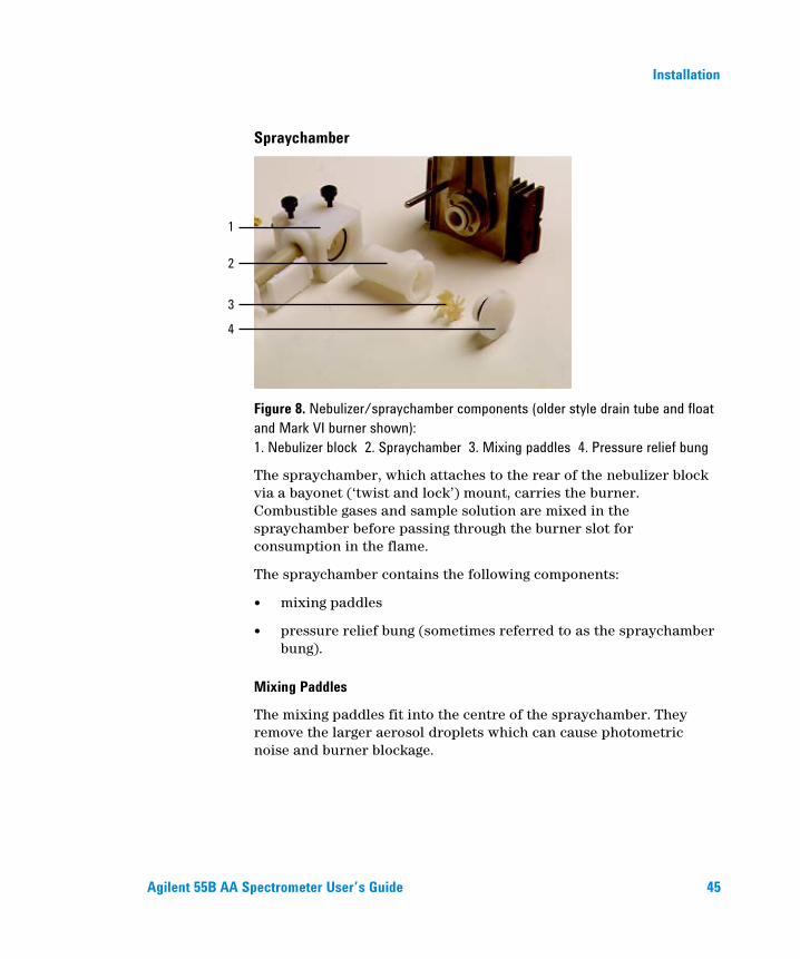
Figure 8. Nebulizer/spraychamber components (older style drain tube and float and Mark VI burner shown): 1. Nebulizer block 2. Spraychamber 3. Mixing paddles 4. Pressure relief bung
The spraychamber, which attaches to the rear of the nebulizer block via a bayonet (‘twist and lock’) mount, carries the burner. Combustible gases and sample solution are mixed in the spraychamber before passing through the burner slot for consumption in the flame.
The spraychamber contains the following components:
mixing paddles
pressure relief bung (sometimes referred to as the spraychamber bung).
Mixing Paddles
The mixing paddles fit into the centre of the spraychamber. They remove the larger aerosol droplets which can cause photometric noise and burner blockage.
1
2
3
4

Installation
46 Agilent 55B AA Spectrometer User’s Guide
One end of the mixing paddles has a boss (or knob) at the center of the blades. At the other end three of the blades have small bumps on their edges. When installing the mixing paddles, the boss end goes to the front of the spraychamber. The bumps hold the paddles in position.
Pressure Relief Bung
A pressure relief bung is located at the rear of the spraychamber. In the unlikely event of a flashback occurring, this bung is ejected away from the operator to relieve excess pressure.
The burner/spraychamber system incorporates an interlock designed to do two things:
inhibit ignition if the pressure relief bung is not correctly fitted
shut down the flame if the bung is ejected as a result of a flashback.
NOTE Even if the spraychamber is already assembled, check that it is correctly assembled before installing it in the sample compartment. (Instructions for disassembling the spraychamber are provided on Page 108. Especially check the correct positioning of the mixing paddles as described in step 1 below.
Assembling the Spraychamber
NOTE Touching or otherwise contaminating any part of the mixing paddles will degrade the performance of the spraychamber. You must be careful to avoid contaminating the mixing paddles when handling them. For cleaning instructions, refer to the Maintenance chapter.

Installation
Agilent 55B AA Spectrometer User’s Guide 47
To assemble the spraychamber:
1 Position the boss end of the mixing paddles in the opening at the rear of the spraychamber, being careful not to contaminate them. Align the mixing paddles so that an opening between any two of the front blades is at the bottom.
2 Slide the paddles into the spraychamber until the rear paddle is about to enter the hole.
3 Check that the paddles are still positioned as described in Step 1, then carefully push the back paddle into the spraychamber using a blunt, inert and clean object (for example, a plastic stirring rod) until the paddles are stopped by the shoulder.
4 Wet the O-ring of the pressure relief bung with distilled water to lubricate it.
5 Insert the pressure relief bung into the rear of the spraychamber and push it firmly into position as far as it will go using a slight twisting motion.
To join the spraychamber and nebulizer block:
1 Place the O-ring in the recess at the rear of the nebulizer block as shown in the following picture.
Figure 9. O-ring in place in the nebulizer block

Installation
48 Agilent 55B AA Spectrometer User’s Guide
2 Holding the nebulizer block in one hand, insert the front end (bayonet mount) of the spraychamber into the rear end of the nebulizer block, using a clockwise twisting motion as you push the spraychamber into the nebulizer block to lock the bayonet mount.
Attaching the drain tube/float/liquid trap to the nebulizer block: This is for products with serial numbers before 0110xxxx. For products with serial numbers 0110xxxx and later, refer to the instructions on Page 50.
1 Screw the plastic drain tube into the bottom of the nebulizer block.
WARNING
Explosion Hazard Failure to install the drain tube will cause violent and loud explosions to occur in both the liquid trap and drain vessel when the flame is lit. The explosion may be severe enough to cause death, personal injury or damage to the instrument or laboratory. NEVER attempt to light a flame with the drain tube missing.
2 Refer to the following picture and insert the float (1) in the liquid
trap.
Figure 10. Top view of liquid trap showing correct placement of float
1

Installation
Agilent 55B AA Spectrometer User’s Guide 49
WARNING
Fire Hazard To ensure correct operation, the float must be inserted in the trap with the open end of the float facing down and the concave section facing inwards.
3 Add the appropriate solvent to the liquid trap until the float just
starts to rise.
WARNING
Explosion Hazard Failure to fill the liquid trap will cause violent and loud explosions to occur in both the liquid trap and drain vessel when the flame is lit. NEVER attempt to light a flame unless the liquid trap is full.
4 Attach the liquid trap to the bottom of the nebulizer block by
inserting the end of the plastic drain tube into the liquid trap and using a counter-clockwise twisting motion to engage the bayonet lock.
Figure 11. Complete nebulizer/spraychamber assembly

Installation
50 Agilent 55B AA Spectrometer User’s Guide
You should now install the complete spraychamber/nebulizer assembly (as pictured above) in the sample compartment of the instrument as described on Page 52.
Attaching the drain tube/float/liquid trap to the nebulizer block (products with serial numbers 0110xxxx and later. For products with serial numbers before 0110xxxx, refer to the instructions on Page 48.)
1 Hold the nebulizer block/spraychamber assembly upside down so that the float falls down clear of the hand, and screw the new drain tube into the nebulizer block. Refer to Figure 12.
WARNING
Explosion Hazard Failure to install the drain tube will cause violent and loud explosions to occur in both the liquid trap and drain vessel when the flame is lit. The explosion may be severe enough to cause death, personal injury or damage to the instrument or laboratory. NEVER attempt to light a flame with the drain tube missing.
Figure 12. Screw the drain tube into the nebulizer block
2 With the two vent nipples aligned with the nebulizer, lower the drain tube into the trap, ensuring that the float drops into the space between the two ribs that are opposite the two vent nipples. Refer to Figure 13.

Installation
Agilent 55B AA Spectrometer User’s Guide 51
Figure 13. Lower the drain tube and float into the trap
3 Push the trap home and then twist it 1/4 turn clockwise to lock it into position. Refer to Figure 13.
Figure 14. Lock the trap into position
WARNING
Explosion Hazard Failure to fill the liquid trap will cause violent and loud explosions to occur in both the liquid trap and drain vessel when the flame is lit. The explosion may be severe enough to cause death, personal injury or damage to the instrument or laboratory. NEVER attempt to light a flame unless the liquid trap is full.

Installation
52 Agilent 55B AA Spectrometer User’s Guide
You should now install the complete spraychamber/nebulizer assembly (as pictured above) in the sample compartment of the instrument as described in the next section.
Installing the Spraychamber/Nebulizer Assembly
To install the spraychamber/nebulizer assembly:
1 Place the spraychamber/nebulizer assembly in position in the sample compartment so that the fuel and oxidant outlet nipples on the instrument are engaged in the fuel and oxidant ports on the nebulizer block.
2 Push the assembly firmly sideways. Tighten the knurled retaining screws alternately (one turn each at a time) so that the assembly is pulled up evenly into place. Tighten both screws firmly with the fingers only.
3 Place a suitable wide-necked waste vessel in a convenient position at floor level. The waste vessel must be made of a non-glass material which will not shatter in the event of a flashback or fire. Locate your waste vessel in an open well-ventilated area where you can see it. Never locate the waste vessel in a confined space. Use small stable vessels and empty them frequently. Do not accumulate large volumes of flammable liquid.
4 Attach a convenient length of 9 mm ID tubing to the lower outlet of the liquid trap. Lead the free end of this tubing to your waste vessel. Ensure the tubing is relatively straight and free of kinks, sharp bends or upward slopes (the waste liquid must be allowed to drain freely into the waste vessel). The free end of the tubing must remain above the level of the liquid in the vessel.
Installation
Agilent 55B AA Spectrometer User’s Guide 53
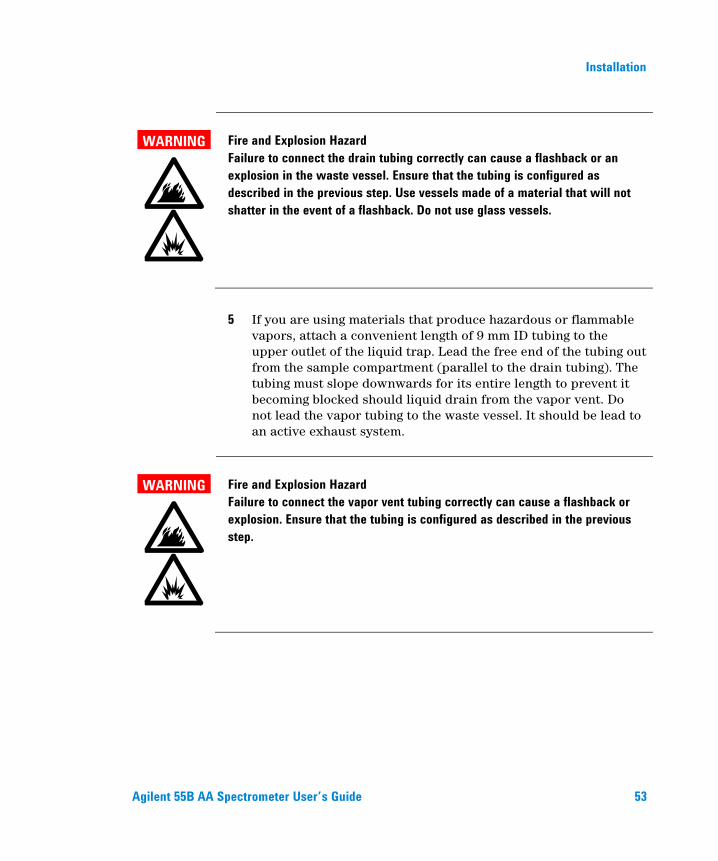
WARNING
Fire and Explosion Hazard Failure to connect the drain tubing correctly can cause a flashback or an explosion in the waste vessel. Ensure that the tubing is configured as described in the previous step. Use vessels made of a material that will not shatter in the event of a flashback. Do not use glass vessels.
5 If you are using materials that produce hazardous or flammable
vapors, attach a convenient length of 9 mm ID tubing to the upper outlet of the liquid trap. Lead the free end of the tubing out from the sample compartment (parallel to the drain tubing). The tubing must slope downwards for its entire length to prevent it becoming blocked should liquid drain from the vapor vent. Do not lead the vapor tubing to the waste vessel. It should be lead to an active exhaust system.
WARNING
Fire and Explosion Hazard Failure to connect the vapor vent tubing correctly can cause a flashback or explosion. Ensure that the tubing is configured as described in the previous step.

Installation
54 Agilent 55B AA Spectrometer User’s Guide
Burner There are two types of burner available for use with your Agilent AA system: an air-acetylene burner or a nitrous oxide-acetylene burner. Both burners include an interlock key designed to prevent ignition if either a burner is not fitted or a burner is fitted which is not suitable for the flame type selected. A handle allows you to rotate the burner to any position.
NOTE Only Mark VI A or Mark 7 burners should be used with this system. Previous versions should not be installed.
WARNING
Explosion and Fire Hazard and Hot Surface Improper or careless use of burners can create explosion hazards and fire hazards which can cause death, serious injury to personnel, and damage to equipment and property. Whenever you handle a burner, remember that it may be very hot. Always use protective gloves to handle hot burners. Always fit the correct burner. Never attempt to use an air-acetylene burner with a nitrous oxide-acetylene flame, as this will cause a flashback. Never interfere with or attempt to bypass burner interlocks. Never attempt to dismantle or modify a burner.
To install a burner:
1 Check the O-ring on the burner. It must be supple and free from nicks or cracks to ensure that the burner makes a gas tight seal with the spraychamber.
2 Position the burner in the sample compartment, with the slot along the optical path and the plate with the warning towards the front of the instrument.
3 Align the interlock key with the guide in the burner adjuster.

Installation
Agilent 55B AA Spectrometer User’s Guide 55
4 Lower the burner so that the interlock key enters the guide in the burner adjuster and the burner neck enters the hole for the burner in the spraychamber.
5 Push the burner down as far as it will go using a slight twisting motion.
WARNING
Fire and Explosion Hazard Leaking gas mixtures may explode or ignite and cause injury and damage. Do not damage the O-ring when fitting the burner.
6 Squeeze the prongs of the rotation handle together to move the
handle left or right to rotate the burner.
You should align the burner after installing it (refer to Page 83.
Sample Compartment Front Panel The sample compartment front panel is designed to reduce heat and radiation hazards. Always fit this panel before using your Agilent AA.
To fit the sample compartment front panel:
1 Position the panel in the sample compartment, orientated as shown in the picture at the start of this section.
2 Align the panel so that the two small holes fit over the two lugs on top of the burner adjuster, and lower the panel until it rests on the burner adjuster.

Installation
56 Agilent 55B AA Spectrometer User’s Guide
Flame Shield The flame shield hinges onto the front of the sample compartment and is designed to reduce heat and radiation hazards from the flame. An interlock prevents you from igniting the flame unless the flame shield is closed. Always fit the flame shield before using your Agilent AA, and leave it closed unless you need access to the burner.
WARNING
Eye Hazard Some flames emit hazardous levels of UV radiation, which can cause cataracts and skin cancer. Always keep the flame shield, sample compartment front panel and chimney in place when the flame is operating.
To fit the flame shield:
1 Hook the flame shield onto the bar at the top of the sample compartment.
2 Lower the flame shield until it rests on the stainless steel bosses on either side of the sample compartment.
To remove the flame shield, lift it up and unhook it from the front of the sample compartment.
WARNING
Hot Surface The chimney and flame shield may become very hot during operation and cause severe burns if touched. Always wear protective gloves when handling a hot chimney.

Interface
Agilent 55B AA Spectrometer User’s Guide 57
4. Interface Introduction 57 Display 58 Keypad 61 Agilent 55B AA Pages 63 Load Method Page 63 Instrument Parameters Page 63 Measurement Parameters Page 65 Options Page 66 Optimization Page 69 Calibration Parameters Page 69 Results Page 70 Navigating the Interface 71 Changing Pages 71 Selecting Menus 71 Moving Between Fields 72
This chapter provides an overview of the Agilent 55B AA user interface to help you become familiar with its various components. You should read through this chapter while exploring the interface.
Introduction The Agilent 55B AA user interface consists of the following:
Liquid Crystal Display—LCD
Keypad
Speaker, to provide audible prompts or warnings
Serial port, to LIMS/printer output

Interface
58 Agilent 55B AA Spectrometer User’s Guide
Memory for storage of up to 30 customized methods.
Figure 15. Agilent 55B AA keypad and display area
Display The display is divided into four areas: status area, signal bar, page area and message line, each of which is discussed below.
Status Area
The status area displays the method details and solution results. Method details include settings relating to the method currently loaded, such as method number and element. Solution results include the mean value (in absorbance (Abs) or transmittance (T) if the method is uncalibrated, or concentration if calibrated) and precision (in %RSD or %Pr, depending on the measurement mode). Method details are displayed in normal font. Results are shown in enlarged font.
Interface
Agilent 55B AA Spectrometer User’s Guide 59
Signal Bar
The signal bar appears at the top of the display screen on certain pages, spans the entire width of the screen, and graphically displays signal values, depending on the type of reading that the instrument is performing. If you are optimizing a hollow cathode lamp or D2 lamp, the signal bar will display the lamp emission. If you are optimizing the flame signal, the signal bar will display the atomic absorption or emission.
The signal bar is only active when the Optimize, Calibration, or Results page is selected. At other times the bar is blank.
Page Area
The page area displays the name of the current page and page-specific information such as input fields and text or graphics. Refer to Page 63 for details on the different pages in the system.
Message Line
The message line displays information/warning/error messages. This information may be the permissible range of the current parameter, or a warning or error message. Refer to Chapter 8 for a detailed description of possible error messages, and possible solutions to these errors.
It also informs you of the calibration status of the method. If the text “Cal” appears in the message line, the method has been calibrated. The text “Rslp” indicates the calibration has been resloped. No text (“ ”) indicates that the method has not been calibrated.

Interface
60 Agilent 55B AA Spectrometer User’s Guide
A number of icons may appear in the message line, to provide you with instrument status information. Some of these icons are animated, to indicate that the instrument is active. The icons and their meanings are as follows:
Instrument busy - please wait
Monochromator slewing
Instrument peaking
Slit changing
D2 lamp warming up
Instrument finding zero order
No burner fitted
Air/acetylene burner and ignition sequence
N2O/acetylene burner (showing narrower slit) and ignition sequence
Gas type and oxidant pressure status icons are as follows:
Air-acetylene, oxidant pressure present
Air-acetylene, no oxidant pressure
Air only, oxidant pressure present
Air only, no oxidant pressure
Nitrous oxide-acetylene, oxidant pressure present
Nitrous oxide-acetylene, no oxidant pressure
NOTE Gas type icons are only displayed during times of other instrument activity.

Interface
Agilent 55B AA Spectrometer User’s Guide 61
Keypad The keypad keys are divided into a number of groups, as discussed below.
Page Keys
There are seven page keys, each of which take you to a specific page in the system. These keys are: Load Method, Instrument Parameters, Options, Optimization, Measurement Parameters, Calibration Parameters and Results. For a description of the function of each page, refer to Page 63.
The Calibration Parameters key is also used, in conjunction with the Alt key, to view the calibration graph. For details, refer to Page 90.
Numeric Keys
The numeric keypad (0-9 and decimal point) is used to enter entry field values. A Clear button (Clr) is also included in this group to delete any values entered.
Cursor Keys
There are four cursor keys: Up, Down, Left, and Right. They are used to move around the display. The Enter key is used to update the parameter setting with the new value.
NOTE If the cursor is moved out of a field without Enter being pressed, the field’s contents returns to its previous value.
Enter is also used on the Optimization page to perform a Rescale command (see Page 81).

Interface
62 Agilent 55B AA Spectrometer User’s Guide
Alt
Alt is used in conjunction with other keys to modify their meaning. Use the Alt key with the Up or Down keys to change the display contrast. Press the Alt and Read keys together to perform an Instrument Zero, or Alt and Calibration Parameters to display the calibration graph. Pressing Alt alone has no effect.
The table below lists the shortcuts available via the keypad.
Table 1. Keypad shortcuts available
Key sequence Action Available
ALT+Calibrate Display calibration graph Anywhere ALT+Result Display error log Anywhere ALT+Up Increase LCD contrast Anywhere ALT+Down Decrease LCD contrast Anywhere ALT+Clear Flame shutoff (for N2O) Anywhere ALT+Enter Print method (if Serial==PRINTER) Anywhere ALT+. Save general info EEPROM Anywhere ALT+50 General diagnostic page Anywhere ALT+51 EEPROM data diagnostic Anywhere ALT+52 Motor diagnostic page Anywhere ALT+53 RS232 loopback test Anywhere ALT+54 SIPS arm pressure page Anywhere ALT+59 Keyboard diagnostic page Anywhere ALT+Calibrate Exit keyboard diagnostics ALT+Results Exit keyboard diagnostics ALT+Left Menu scroll text Any menu ALT+Right Menu scroll text Any menu ALT+Read Instrument zero Optimization page Read Read next standard Calibration page ALT+Read Instrument zero Calibration page Reslope Perform reslope Calibration page ALT+Reslope Drop reslope standard Calibration page Read Take next reading Results page ALT+Read Instrument zero Results page Reslope Perform reslope Results page

Interface
Agilent 55B AA Spectrometer User’s Guide 63
Key sequence Action Available
ALT+Reslope Drop reslope standard Results page Right Prime SIPS pump page Results page Up Increment next sample Results page Down Decrement next sample Results page Clear Clear result window, start new page if
Serial=PRINTER Results page
Miscellaneous
The Read key is used to measure a solution (see Pages 89 and 92). The Reslope key is used to select the reslope standard, and to perform a reslope operation (see Page 89).
Agilent 55B AA Pages The system consists of seven pages, each accessed by pressing its corresponding key. The pages are as follows:
Load Method Page The Load Method page is used to load either a user method or a cookbook method. You should follow the prompts appearing on this page to load the type of method you want. For more information, refer to Page 77.
Instrument Parameters Page The Instrument Parameters page is used to set the instrument parameters, and save and delete methods.
NOTE The element can only be selected by loading an appropriate method (user or cookbook).
This page includes the following instrument-specific fields:
Interface
64 Agilent 55B AA Spectrometer User’s Guide
Instrument Mode
Defines the mode you want to use, ‘Absorbance’ or ‘Emission’ (default is Absorbance).
Active Lamp
Defines which lamp position to use (default is 1) in ‘Absorbance’ mode.
Active Current
Defines the current for the active lamp (default setting is the recommended current for the lamp of the selected element).
Standby current
Defines the current for the standby lamp (default is 0.0).
D2 Correction
Only available on instruments with D2 background correction. Defines whether D2 correction is to be used or not (default is no).
Gas Type
Defines the flame type to be used for the analysis (default is the recommended gas type for the selected element).
Wavelength
Defines the wavelength to be used for the current element (default is the first listed wavelength).
NOTE The listed wavelengths are element and instrument-mode specific.
Other λ
Defines the wavelength to be used when ‘Other’ is selected in the Wavelength field. Range is 180.0–900.0.
Interface
Agilent 55B AA Spectrometer User’s Guide 65
Slit
Defines the spectral bandwidth (SBW) for the current wavelength (default is the recommended slit width for the current wavelength).
Save Method
Saves the current method and calibration (if completed) to memory.
NOTE Any conditions being used on the Measurement Parameters page and Options page should also be saved using this function.
Delete Method
Deletes a method from memory.
Measurement Parameters Page This page is used to set the measurement parameters.
NOTE Due to the nature of the field type, the Measurement mode is located on the Options page (see Page 66). This parameter must be set prior to setting the remaining measurement parameters.
Batch No. & Next Sample
Identifies the next sample to be measured. This has no effect on the reading.
Pre-read Delay
Defines the time allowed for the sample to reach the light path and for the signal to stabilize.
Read Time
Defines the time for which the signal is measured.

Interface
66 Agilent 55B AA Spectrometer User’s Guide
Replicates
Defines the number of readings per solution. This option is only available in Integration mode.
Precision
Defines the % precision for the PRecision Optimized Measurement Time (PROMT) measurement mode. Not available when SIPS is enabled.
Options Page In addition to selecting the Measurement mode, this page is used to enable options such as SIPS use and serial output, and select the language of the interface.
Measurement Mode
Determines how the signal will be measured. The following modes are available:
Integration
The signal is averaged over the selected ‘Read time’ for the set number of replicates.
PROMT (PRecision Optimized Measurement Time)
The signal is averaged until the desired precision (%RSD) is achieved or until the end of the ‘Read time’.
NOTE When SIPS is being used set this value to 0.3%.
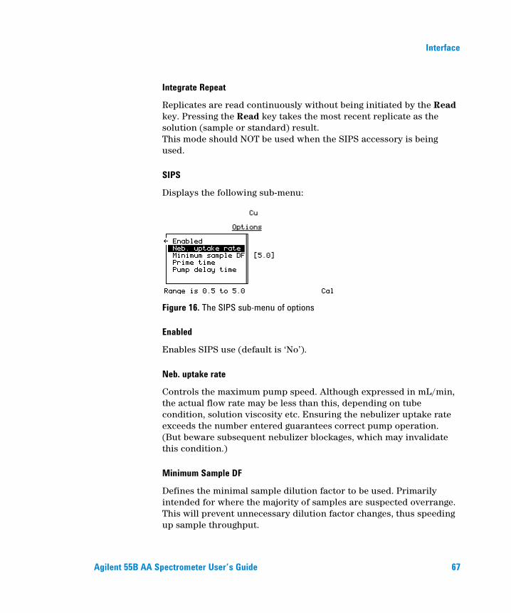
Interface
Agilent 55B AA Spectrometer User’s Guide 67
Integrate Repeat
Replicates are read continuously without being initiated by the Read key. Pressing the Read key takes the most recent replicate as the solution (sample or standard) result. This mode should NOT be used when the SIPS accessory is being used.
SIPS
Displays the following sub-menu:
Figure 16. The SIPS sub-menu of options
Enabled
Enables SIPS use (default is ‘No’).
Neb. uptake rate
Controls the maximum pump speed. Although expressed in mL/min, the actual flow rate may be less than this, depending on tube condition, solution viscosity etc. Ensuring the nebulizer uptake rate exceeds the number entered guarantees correct pump operation. (But beware subsequent nebulizer blockages, which may invalidate this condition.)
Minimum Sample DF
Defines the minimal sample dilution factor to be used. Primarily intended for where the majority of samples are suspected overrange. This will prevent unnecessary dilution factor changes, thus speeding up sample throughput.

Interface
68 Agilent 55B AA Spectrometer User’s Guide
Prime Time
Defines the SIPS pre-read delay, which is the time required to pump solutions introduced with SIPS through the pump tubing from the solution vessel to the T-piece.
Pump Delay Time
Defines the time taken for the sample absorbance to reach equilibrium after a change in pump speed and for the signal to stabilize. See Chapter 5 for information on how to use SIPS.
Serial Port
Displays the following sub-menu:
Figure 17. The Serial port sub-menu of options
Text Style
Enables LIMS or printer output (default is none). All output requires the ‘Baud rate’ to be set correctly. ‘LIMS’ output has comma-delimited fields. ‘Printer’ output has space-delimited fields.
See Page 93 for details on printing solution results.
Baud Rate
Defines the baud rate to be used for the serial port. Default is 9600.
Lines Per Page
Used when ‘Printer’ is selected as the text style (default is 66). Each page has a header. Form feeds are used to separate pages.

Interface
Agilent 55B AA Spectrometer User’s Guide 69
Language
Selects the language of the interface (default is English). Refer to Page 77 for instructions on how to change the language of the interface.
Optimization Page The Optimization page is used to optimize the hollow cathode lamps (and D2 lamp), and to optimize the signal. In Absorbance mode there are up to three options present on this page: HC lamp, D2 lamp and Signal. In Emission mode, there is only one option present, Signal, because during emission optimization the system uses the highest standard to carry out the wavelength peaking procedure (i.e., no lamps are used).
The signal bar appearing at the top of the page facilitates optimization of the lamps, burner position and impact bead position to obtain the optimum signal.
Refer to Page 81 for instructions on optimizing the system.
Calibration Parameters Page This page is used to define the standards to be used for the calibration, measure the standards, and select the reslope.
Standard Conc. 0
This field is set to zero, and is not editable, but allows the blank to be measured.
Standards 1…5
Defines the concentrations of the calibration standards. The value must be greater than zero and have four significant figures, with 0-3 decimal places. No two standards may have the same value, and they must be entered in increasing order. Entering a value of zero will delete the current and subsequent standards.

Interface
70 Agilent 55B AA Spectrometer User’s Guide
The reslope standard is set by selecting the desired standard and pressing the Reslope key. The standard selected will be marked with an asterisk beside it to indicate it is the Reslope standard. See Page 90 for more information.
NOTE If SIPS is enabled, the cursor is restricted to the last entry field, which is the concentration of the bulk standard. Standards 1-4 are calculated from the bulk standard. The reslope standard is fixed at 3. See Page 91 for more information.
Results Page The Results page displays the solution results in tabular format, and displays such information as sample name, concentration, %RSD or precision, mean solution reading, dilution factor and the last replicate value.
Figure 18. The Results page
The Sample column displays text in the form nnn for a sample, Std-n for a standard, and Reslope for the reslope standard.
The Conc column displays the concentration values of the solutions measured, or the text UNDER or OVER if the solution is underrange or overrange, or UNCAL if the method is uncalibrated.
The Precision column displays %RSD in Integration mode, %Pr in PROMT mode and remains blank in Integrate Repeat mode (with the heading %Pr).
The Mean column always displays the mean reading for each solution.

Interface
Agilent 55B AA Spectrometer User’s Guide 71
The DF (dilution factor) column only includes values if SIPS is enabled, and will be within the range 1.000…200.0.
The Reps (last replicate value) column is only used for Integration mode, displaying the value of each replicateas it is calculated. Each value overwrites the previous value.
If a new method is loaded, or the Measurement mode or Instrument mode is changed, the contents of the Results window are cleared.
Navigating the Interface
Changing Pages To access a particular page, press the key that corresponds to the desired page. Any modifications made to the previous page will be kept, and downloaded to the instrument as the page is exited. Changes made on a given page are only executed when the current page is exited (another page is selected). An exception to this is when changing from the Load Method page to the Instrument Parameters page (or vice versa). The parameters are not downloaded at this time, allowing you to load a method and edit the instrument parameters in one go, rather than having the instrument settings updated twice (upon each page exit).
Selecting Menus For Command menus (i.e., single-level menus appearing in the left of the screen) use the Up and Down keys to move from one item to the next, and, if necessary, press Enter to select the desired option.
Figure 19. An example of a Command menu

Interface
72 Agilent 55B AA Spectrometer User’s Guide
If the menu is a Parameter menu (i.e., the left hand list box contains items which access other sub-menus) you must press the Right arrow key on the required menu option to access the available sub-menu.
Figure 20. An example of a Parameter menu
NOTE An arrow appearing in the frame around a menu indicates there are additional items available. Use the Up/Down arrow keys to scroll through the list, or the Left/Right arrow keys to move from one menu to the next.
In the previous example you would press the Right arrow key to access the available options for the ‘Instrument mode’ field, use the Up/Down arrow keys to move the highlight to the desired option and press Enter to select it. Pressing Enter accepts the current value and returns the cursor to the left hand field.
Moving Between Fields The cursor shows where the current focus is. When the cursor is on an entry field, the entire field is highlighted. To move between entry fields, use the Up/Down arrow keys.

Interface
Agilent 55B AA Spectrometer User’s Guide 73
Figure 21. The Measurement Parameters page, with the focus on the ‘Read time’ field
As data is entered (via the Numeric keys) it appears at the end of the field. If Clr is pressed the entire field value is deleted. When Enter is pressed, the cursor moves to the next field (providing the value is valid). If the value entered is invalid, the cursor remains on the entry field and the value is not accepted.

Interface
74 Agilent 55B AA Spectrometer User’s Guide
This page is intentionally left blank.

Operation
Agilent 55B AA Spectrometer User’s Guide 75
5. Operation Pre-Analysis Checklist 75 Starting the System 76 Method Development 77 Optimization 81 Nebulizer Setup 86 Calibrating the Method 89 Sample Measurement 92 Results 93 Shutting Down the System 94
This chapter provides instructions for running your Agilent 55B AA instrument, including how to develop methods, optimize the system, perform measurements and print the results.
This chapter assumes you have correctly installed the appropriate hardware as described in Chapter 3, and are familiar with the interface as described in Chapter 4.
Pre-Analysis Checklist To prepare your Agilent 55B AA spectrometer for analysis:
1 Check that all the required hardware (including SIPS and printer if necessary) is correctly installed as per the instructions in Chapter 3 and any additional accessory manuals.
2 Turn on the instrument and any peripheral accessories as described on Page 76.
3 Ensure the exhaust system is working. To do this, hold a thin single-ply tissue up to the mouth of the extraction hood, or use the smoke from an extinguished match. The tissue or smoke should be drawn towards the hood.

Operation
76 Agilent 55B AA Spectrometer User’s Guide
4 Check the gas supplies to make sure you have enough gas to complete your analysis. You must also check that the acetylene cylinder pressure is above 700 kPa (about 100 psi) to ensure that acetone is not drawn into the instrument.
5 Set the delivery pressure of the gases to the following: Recommended Permissible
kPa PSI kPa PSI Acetylene 75 11 65-100 9.5-14.5
Air 350 50 245-455 35-65 Nitrous oxide 350 50 245-455 35-65
6 Inspect the gas hoses for damage, replacing any damaged hoses. Turn on the gas supplies to your instrument and test all hoses and connections for leaks. If a leak is found, turn off the gas supplies immediately and rectify the problem.
7 Develop or load a method as described on Page 77.
8 Optimize the system as described on Page 81.
9 Set the nebulizer uptake rate as described on Page 86.
10 Calibrate the system as described on Page 89.
11 Proceed with your analysis.
Starting the System The power switch is a rocker type, located on the front of the instrument on the left side. Switch this to ‘I’ to start the system. The green indicator light should come on.
When you switch on your instrument, the startup screen will appear in the display area while the instrument performs its initialization tests. When the initialization setup is complete the Load Method page is displayed.
For instructions on how to start any accessories, refer to the manuals supplied with the accessories.

Operation
Agilent 55B AA Spectrometer User’s Guide 77
Method Development A method stores the parameters to be used for analysis, such as instrument, measurement and calibration settings. You must have a method loaded in order to run samples. There are two types of methods—‘user’ methods (defined by the user) and ‘cookbook’ methods (containing recommended settings for the selected element).
Selecting the Language of the Interface Before proceeding you may need to select the language of the interface. This is done on the Options page.
To change the language of the interface:
1 Press the Options key. If the Options page displays the SIPS sub-menu, press the Left arrow key to return to the main menu (see Page 66 for more information).
2 Move the cursor to ‘Language’ and press the Right arrow key.
3 Move the cursor to the desired language from the list of available options and press Enter.
NOTE Keyboard overlays are also available in these languages (see Chapter 7 for ordering information).
Loading a Method You can load a ‘cookbook’ method, customize your own ‘user’method, or load an existing ‘user’ method.
To load a cookbook method:
1 Press the Load Method button.
2 Select the ‘Cookbook’ option.
3 Select the appropriate element group.
4 Select the required element from the list and press Enter.

Operation
78 Agilent 55B AA Spectrometer User’s Guide
The cookbook method will be loaded and the following parameters updated accordingly: element, method number, instrument mode, active lamp current, gas type, wavelength and slit width. In addition, all previous standard concentration values will be deleted.
To customize a method:
1 Load the cookbook method for the required element as described previously and modify the parameter settings as necessary (see the following sections for instructions on setting the various parameters).
2 Save the method on the Instrument Parameters page as described on Page 80.
To load/modify an existing user method:
1 Press the Load Method button.
2 Select ‘User’ methods and press Enter.
3 Select the method you wish to use.
4 Modify the method as required.
Setting the Instrument Parameters The instrument settings are defined on the Instrument Parameters page.
To set the instrument parameters, select the Instrument Parameters page and specify:
the ‘Instrument mode’ (Absorbance or Emission)
the ‘Active lamp’ (position 1 or 2)
the ‘Active current’ for the active lamp
the ‘Standby current’ for the standby lamp
whether ‘D2 correction’ is on or off
the ‘Gas type’
the ‘Wavelength’
the spectral bandwidth (the width of the ‘Slit’).
For more information, see Page 63.

Operation
Agilent 55B AA Spectrometer User’s Guide 79
Setting the Measurement Parameters All measurement parameters are set on the Measurement Parameters page, with the exception of the Measurement mode and use of SIPS, which are set on the Options page.
To set the measurement parameters:
1 Select the Options page (see Page 66) and specify:
a the ‘Measurement mode’
b Whether ‘SIPS’ is enabled or not. If you choose to enable SIPS you will also need to set the SIPS parameters (see Page 66).
2 Select the Measurement Parameters page and specify:
a ‘Next sample’ to be measured.
b ‘Batch no‘
c ‘Read time’
d Number of ‘Replicates’ (Integration mode only)
e ‘Precision’ (PROMT mode only)
f ‘Pre-read delay’
For more information, see Page 65.
Defining the Calibration Standards Calibration standards are entered on the Calibration Parameters page. Up to five standards may be defined. Calibration standards must be unique and they must be entered in increasing order.
Cal Zero is not editable, and is included solely to allow for measurement of the blank. The field value is always zero.
NOTE If SIPS is enabled (on the Options page) the only editable field on the Calibration Parameters page is Conc5, which represents the concentration of the bulk standard. Conc1...4 are calculated from the bulk standard, and the Reslope standard is set at 3. For more information, see Page 90.

Operation
80 Agilent 55B AA Spectrometer User’s Guide
To enter the calibration information:
1 Select the Calibration Parameters page.
2 Move the highlight to the ‘Conc1’ field and enter the concentration of standard 1. The number of decimal places entered will set the number of decimal places used for the remaining standard values. Even when changing the number of decimal places, all concentrations must still be valid (not overrange or identical).
3 Enter the remaining standard concentrations. The values must be unique and increasing.
4 Set the reslope standard to be used (if required) by moving the cursor to the appropriate standard and pressing the Reslope key. An asterisk indicates the reslope standard.
For more information, see Page 69.
Saving/Deleting Methods Methods are saved on the Instrument Parameters page. There are 30 slots for you to save your customized methods. Slots that are occupied are displayed on the Load Method page. You may save a method into any slot, even if the slot is already occupied by an existing method. The existing method will be overwritten by the new method (without a request for confirmation).
To save a method:
1 Press the Instrument Parameters button.
2 Move the highlight to the ‘Save Method’ option and press Enter.
3 Select an empty position and press Enter.
The method will be saved in the selected slot, with the slot number and method element displayed in the list.
To delete a method:
1 Press the Instrument Parameters button.
2 Move the highlight to the ‘Delete Method’ option and press Enter.
3 Move the highlight to the method in the list you wish to delete and press Enter. The method will be deleted, leaving an empty slot in the list.

Operation
Agilent 55B AA Spectrometer User’s Guide 81
Optimization This section describes how to optimize the various components of the Agilent 55B AA system, including the lamp, burner and flame signal.
Aligning Lamps
Hollow Cathode Lamps
If you are developing a new method, install the lamp and note the position, ensuring this position is setup in the method for that element. The numbers of each lamp position are clearly marked. You will need to enter the position number of the lamp on the Instrument Parameters page.
If you are using a lamp with an existing method, review the method to find where the lamp must be installed, install the lamp in this position and ensure the position is setup in the method for this element.
You should align a hollow cathode lamp if:
you have just installed the lamp
you need the best possible signal to noise ratio
you are using a non-Agilent lamp
you are using a position previously used for a non-Agilent lamp.
You do not need to align the lamps in Emission mode, because lamps are not used (signal optimization is performed while aspirating the top/bulk standard).
To align a hollow cathode lamp:
1 Load an appropriate method, ensure the required lamp position is setup in the SpectrAA software, and allow the lamp time to warm up (approximately 15 minutes). If the lamp is not glowing, review the method and set the ‘Active lamp’ and ‘Active current’ on the Instrument Parameters page.
2 Press the Optimize button and ensure nothing is in the optical path. (The ‘HC lamp’ option is selected automatically upon entering the page.)

Operation
82 Agilent 55B AA Spectrometer User’s Guide
3 While watching the lamp signal bar on the display, slowly turn one of the lamp adjustment knobs. If the signal decreases, turn the knob in the other direction, until you find the maximum signal. If the HC lamp signal is too small, first check that you have the correct lamp for the current method. If so, press Enter to Rescale. This will bring the signal back into range for display. You should also Rescale if the signal becomes too large.
4 Repeat the previous step with the other adjustment knob.
D2 Lamp
The D2 lamp only needs aligning after a new one has been installed (refer to Chapter 6 for instructions on installing a new D2 lamp).
To align a D2 lamp:
1 On the Optimize page, select the ‘D2 lamp’ option.
2 While watching the lamp signal bar on the display, slowly turn one of the D2 lamp adjustment knobs (located on the front of the D2 lamp compartment). If the signal decreases, turn the knob in the other direction, until you find the maximum signal. If the D2 lamp signal is too small, first check that you have installed the D2 lamp correctly (refer to Page 109). If so, press Enter to Rescale. This will bring the signal back into range for display. You should also Rescale if the signal becomes too large.
3 Repeat the previous step with the second D2 lamp adjustment knob.

Operation
Agilent 55B AA Spectrometer User’s Guide 83
Aligning the Burner To align the burner:
1 Use one of the Agilent supplied burner cleaning and alignment strips (or a business card) to locate the light path.
2 Rotate the burner by squeezing the prongs of the rotation handle, until the slot is parallel to the light path.
NOTE Burner cleaning and alignment strips are available from Agilent.
3 Place the card halfway along the burner slot. Position the card with the vertical line perpendicular to the slot, and adjust the burner height until the light beam falls within the target area.
Figure 22. Aligning the burner
4 Check that the slot is parallel to the light path by placing the card at the ends of the burner slot. Readjust if necessary.
You can now light the flame and optimize the signal.
Lighting the Flame Prior to lighting the flame you must ensure that:
the working area is completely clear of all hazardous materials including corrosive liquids and flammable solvents
the liquid trap is filled with an appropriate solvent

Operation
84 Agilent 55B AA Spectrometer User’s Guide
the drain tube is positioned correctly in the waste vessel, with the end of the tube as high as possible in the vessel above the expected liquid level
the correct burner is fitted
the flame shield, sample compartment front panel and chimney have been fitted
you have checked the exhaust system and gas supplies as described on Page 75.
To light the flame:
1 Press the ‘Flame on’ button (the black button on the left of the instrument) and keep it pressed until the flame ignites. If the ignition sequence times out before the flame ignites, release the button, wait about five seconds, and restart the sequence.
WARNING
Explosion Hazard Operation of a flame with an incomplete safety system can result in a violent explosion that can cause death, injury, hearing loss or property damage. To prevent unsafe ignition of the flame, operation of the inbuilt igniter is inhibited unless all safety interlocks are satisfied. If the igniter fails to operate, and all safety interlocks are satisfied, call an Agilent field service engineer to find and fix the fault. Never use an external igniter to light the flame because this bypasses the inherent self-checking of the safety system.
2 Check the gas regulator settings and readjust if necessary.
3 When the flame has stabilized, adjust the flame conditions.
4 Aspirate 50 mL of the appropriate solvent. When you are not aspirating a solution, you should be aspirating the appropriate solvent.
Operation
Agilent 55B AA Spectrometer User’s Guide 85
Optimizing the Flame Signal To optimize the flame signal:
1 Press the Optimize key and select the ‘Signal’ option.
2 Aspirate the blank and press the Alt and Read keys together to perform an Instrument Zero.
3 Aspirate a standard solution that will give an absorbance of at least 0.2. If you are in emission mode, aspirate the bulk standard or the highest concentration standard.
4 Watch the signal bar and adjust the burner height using the outer knob on the burner adjuster to obtain the maximum absorbance, but keep the burner below the light path. Alternate between aspirating the blank and the top standard, making a note of the nett absorbance value. When this value stops increasing the burner height is correct. The burner height controls the sensitivity and will also influence atomization interferences.
5 Carefully move the burner horizontally by turning the inner adjustment knob on the burner adjuster. In general, once optimized for maximum sensitivity, this position can be used for all analyses.
6 Adjust the impact bead position by gradually turning the impact bead adjustment screw first clockwise, then counter-clockwise to find the maximum absorbance.
TIP You can find the optimum bead position for most applications by aspirating a 5 mg/L solution of copper.
The system is now optimized. You can now take readings, measure your calibration standards, or perform a reslope as described in the following sections.
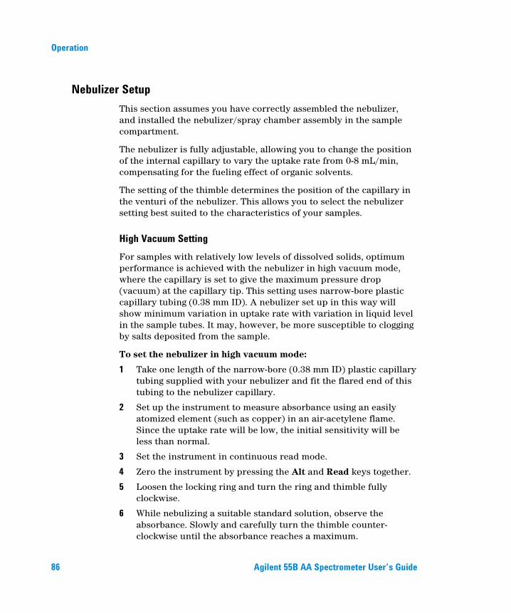
Operation
86 Agilent 55B AA Spectrometer User’s Guide
Nebulizer Setup This section assumes you have correctly assembled the nebulizer, and installed the nebulizer/spray chamber assembly in the sample compartment.
The nebulizer is fully adjustable, allowing you to change the position of the internal capillary to vary the uptake rate from 0-8 mL/min, compensating for the fueling effect of organic solvents.
The setting of the thimble determines the position of the capillary in the venturi of the nebulizer. This allows you to select the nebulizer setting best suited to the characteristics of your samples.
High Vacuum Setting For samples with relatively low levels of dissolved solids, optimum performance is achieved with the nebulizer in high vacuum mode, where the capillary is set to give the maximum pressure drop (vacuum) at the capillary tip. This setting uses narrow-bore plastic capillary tubing (0.38 mm ID). A nebulizer set up in this way will show minimum variation in uptake rate with variation in liquid level in the sample tubes. It may, however, be more susceptible to clogging by salts deposited from the sample.
To set the nebulizer in high vacuum mode:
1 Take one length of the narrow-bore (0.38 mm ID) plastic capillary tubing supplied with your nebulizer and fit the flared end of this tubing to the nebulizer capillary.
2 Set up the instrument to measure absorbance using an easily atomized element (such as copper) in an air-acetylene flame. Since the uptake rate will be low, the initial sensitivity will be less than normal.
3 Set the instrument in continuous read mode.
4 Zero the instrument by pressing the Alt and Read keys together.
5 Loosen the locking ring and turn the ring and thimble fully clockwise.
6 While nebulizing a suitable standard solution, observe the absorbance. Slowly and carefully turn the thimble counter-clockwise until the absorbance reaches a maximum.

Operation
Agilent 55B AA Spectrometer User’s Guide 87
7 Hold the thimble so it cannot turn, then turn the locking ring until it is firmly against the spray chamber body to lock it in place.
The nebulizer is now ready for use. If you have just installed the nebulizer, you should carry out the performance checks described on Page 88.
Low Vacuum Setting In low vacuum mode (the high solids setting) the capillary position is adjusted close to the end of the venturi throat. The greater clearance around the capillary tip reduces clogging caused by solutions with a high solids content. With this setting, the vacuum at the capillary tip is relatively low. Consequently, you must use wide bore (0.64 mm ID) plastic sampling capillary to achieve the uptake rates required for maximum sensitivity. At this setting, the uptake rate is more sensitive to variation in sample liquid level.
To set the nebulizer to low vacuum mode:
1 Fit the wide bore (0.64 mm ID) tubing to the capillary.
2 Loosen the locking ring, and turn the thimble (and ring) fully clockwise.
The nebulizer is now ready for use.
NOTE At this setting, the uptake rate will be sensitive to the hydrostatic head of the liquid in the sample container, thus care is required to minimize variations in liquid levels in the sample and standard containers.
Setting Zero Uptake Rate Before adjusting the nebulizer for use with organic solvents, you should set zero uptake rate as follows, using distilled water as the solvent:
1 Fit the wide bore (0.64 mm ID) tubing to the capillary.
2 Turn the locking ring clockwise until it is up against the nebulizer body.
3 Turn the thimble clockwise as far as it will go.

Operation
88 Agilent 55B AA Spectrometer User’s Guide
4 Aspirating distilled water, turn the thimble counter-clockwise until bubbles emerge from the end of the capillary tubing.
5 Turn the thimble clockwise to the point where bubbling ceases.
This is the zero uptake point (no solution is being aspirated through the nebulizer).
Setting the Uptake Rate for Organic Solvents Because of the fueling effect of organic solvents, you should carefully adjust the nebulizer uptake rate for all analyses involving organic solutions.
Set the uptake rate as follows, using an air-acetylene flame and the selected solvent:
1 Set the nebulizer for zero uptake as described previously.
2 Adjust the gas flows to give a very lean flame.
3 Slowly rotate the thimble clockwise until the flame is beginning to turn fuel-rich (some yellow may be seen).
The nebulizer is now ready for use. If you have just installed the nebulizer, you should carry out the performance checks described in the next section.
Performance Checks You should check the performance of your nebulizer:
At installation
Weekly
When you are using a new type of solution.
To check the performance of your nebulizer:
1 Set the nebulizer to high vacuum mode as per ‘High Vacuum Setting on Page 86, or if you are using organics, set the nebulizer to maximum uptake rate (thimble fully clockwise).
2 Set the instrument up to measure the absorbance of copper in an air-acetylene flame.

Operation
Agilent 55B AA Spectrometer User’s Guide 89
3 With the system fully optimized as described in ‘Optimization’ on Page 81, aspirate distilled water from a 10 mL calibrated cylinder for a carefully timed period and calculate the uptake rate. This should be approximately 5 mL/min.
4 Zero the instrument (press the Alt and Read keys together) while aspirating distilled water.
5 Aspirate a solution of 5 mg/mL copper and note the absorbance reading.
Agilent guarantee an absorbance of 0.75 or better using the Mark 7 flame atomization system under fully optimized conditions.
Calibrating the Method All calibrations use the New Rational algorithm, which provides a quadratic least squares line of best fit in the Abs/Conc vs. Abs domain:
A/C = a + b*A + c*A2
(where A = Absorbance; C = concentration; and a,b,c are curve coefficients).
Calibration standards are measured on the Calibration Parameters page. You can measure the standards manually, or use SIPS to prepare and present the standards automatically from one bulk standard.
NOTE Remeasuring Cal Zero adjusts the signals of all standards.
If you receive an error due to calibration failure, note the error number and refer to Chapter 8 for a description of the problem.
Measuring Standards Manually To measure the calibration standards manually:
1 Define the standards to be used for the calibration as described on Page 79.
2 Select the Cal Blank by moving the focus to the ‘Conc0’ field, then aspirate the blank and press the Read key.

Operation
90 Agilent 55B AA Spectrometer User’s Guide
3 Select ‘Conc1’, aspirate the first standard and press the Read key.
4 Repeat the previous step for the remaining standards.
Measuring Standards Using SIPS 10 Automatic calibration from a single standard can be performed using the SIPS 10. (Refer to the SIPS manual for installation information.)
To calibrate a method using the SIPS 10:
1 Set up the SIPS 10 as described in the SIPS manual.
2 Develop or modify a method as described earlier in this section.
3 To incorporate SIPS operation into the method, enable SIPS on the Options page.
4 In the SIPS sub-menu, set the parameters as required (see Page 66).
5 Select the Calibration Parameters page.
6 Enter the concentration of the bulk standard in the Conc5 field. (When SIPS is enabled, the cursor is restricted to the Conc5 entry field.) The first four standards will be calculated automatically, with the Reslope standard fixed at Conc3.
7 Ensure the diluent tubing is connected to the Mariott vessel.
8 Ensure the pump tubing is placed in the bulk standard and press Read. Standards 0-5 are read in order. The SIPS stops when the calibration is complete.
Displaying the Calibration Graph To view the calibration graph, you must be on the Calibration Parameters page, at least one standard must be defined and measured and the calibration must be valid (i.e., the fit is good).
The calibration graph is viewed by pressing the Calibration Parameters key in conjunction with the Alt key. The cross hairs on the graph can be moved using the arrow keys. The numbers displayed indicate the current signal and concentration of the location of the cross hairs.

Operation
Agilent 55B AA Spectrometer User’s Guide 91
Resloping the Calibration Reslopes are a quick way of adjusting the slope of the current calibration. The nominated standard (indicated on the Calibration Parameters page by an asterisk) is remeasured, a concentration calculated for the Reslope standard (Cr) and compared to the previous known concentration for that standard (Cs). All subsequent sample results are multiplied by the Reslope correction factor, Cs/Cr.
To perform a reslope:
1 On the Calibration Parameters page, move the highlight to the standard you want to use as the Reslope standard.
2 Press the Reslope key to mark the standard as the reslope standard.
NOTE If you are using SIPS the Reslope standard defaults to Conc3.
3 Aspirate the appropriate standard (if you are using SIPS the standard will be prepared automatically).
4 On the Results page, press the Reslope key.
The system will measure the reslope standard selected in the method and update the existing calibration.
NOTE Cal Zero is not remeasured when a Reslope is performed.

Operation
92 Agilent 55B AA Spectrometer User’s Guide
Sample Measurement Samples are measured on the Results page. You can measure samples manually, or use SIPS to facilitate online dilution of overrange samples.
Measuring Samples Manually To measure samples manually:
1 Set the Measurement Parameters as described on Page 79.
2 Press the Results key.
3 Aspirate the appropriate sample (the sample highlighted on the Results page) and press the Read key.
4 Repeat the previous step for the remaining samples.
Measuring Samples with SIPS You can use SIPS 10 to perform automatic dilution of overrange samples.
To measure samples using SIPS 10:
1 Set up the SIPS 10 as described in the SIPS manual.
2 Enable SIPS on the Options page, and set the parameters as required (see Page 66).
3 Set the remaining Measurement Parameters as described in Page 79.
4 Press the Results key.
5 Ensure the diluent tubing is connected to the Mariott vessel.
6 Place the pump tubing in the appropriate sample and press the Read key.
If the sample is overrange, SIPS automatically dilutes the sample online and measurement continues. The dilution factor used is given on the Results page and the final dilution-corrected concentration is reported.

Operation
Agilent 55B AA Spectrometer User’s Guide 93
Results The solution results are displayed on the Results page. Refer to Page 70 for more information on the Results page.
Printing the Results You can print the solution results to an external printer, using the RS-232 9-pin cable to connect the instrument to your PC or printer. If the printer is not a serial printer, use a serial to parallel converter.
To print the results:
1 Set the ‘Text style’ to ‘Printer’ on the Options page, and set the ‘Baud rate’ and ‘Lines per page’.
2 Ensure the RS-232 cable is connected from the serial port on the back of the instrument to the printer.
3 Press the Read key to measure the current solution. As each solution is measured, the result will be sent to the printer.
Output to LIMS System Results can be sent to a LIMS system using the RS-232 output on the rear of the Instrument. To do this:
1 Connect a RS-232 cable from the rear of the instrument to the RS-232 input on the LIMS, for example the COM1 connector on the rear of a PC.
2 Set the baud rate of the connection to that of the controlling system.
Each time the READ key is pressed data is output as follows:
The layout is as follows:
Calibration Standard ID, Concentration, Background Absorbance, Mean Absorbance, Replicates Absorbances.
Batch Number, Sample Number, Concentration, Background Absorbance, Mean Absorbance, Replicates Absorbances.

Operation
94 Agilent 55B AA Spectrometer User’s Guide
Shutting Down the System Prior to shutting down the system at the end of the working day you should aspirate pure solvent for 10 minutes.
To shut down the system:
1 Shut down any accessories according to their manuals.
2 Turn off the instrument.
3 Shut off all gas supplies at the regulators and gas cylinders.
4 Empty the waste vessel.
5 Turn off the exhaust fan.
6 Remove and clean any hardware according to the instructions in the Maintenance Chapter.

Maintenance
Agilent 55B AA Spectrometer User’s Guide 95
6. Maintenance Maintenance Schedule 95 Cleaning 96 Burners 97 Nebulizer 99 Impact Bead 104 Spraychamber 108 Gas Supplies 109 D2 Lamp 109 Fuses 111
This chapter describes how to maintain your Agilent 55B AA system. You should keep a record in your Instrument Log Book of all maintenance carried out. Before you remove any hardware, you must shut down the instrument.
Maintenance Schedule
Daily Check the exhaust system
Check the gas supplies
Check all hoses and connections
Clean the instrument
Clean the burner.

Maintenance
96 Agilent 55B AA Spectrometer User’s Guide
Weekly Clean the lamp and sample compartment windows
Check the air filter, spraychamber and liquid trap.
Yearly Arrange for an Agilent field service engineer to perform
preventative maintenance.
Cleaning
General Clean the instrument surfaces as follows:
1 When you are finished, switch off the instrument and allow it to cool.
2 Remove any hardware present in the sample compartment (refer to the appropriate instructions if necessary).
3 Using a cloth dampened with water, clean the sample compartment, instrument cover, flame shield and chimney. If necessary, use a mild detergent to clean the cover. Do NOT use an abrasive cleaner. When analyzing biological samples, wipe the instrument with chlorhexidine in 95% ethanol.
Windows Clean the windows as follows:
1 Clean the sample compartment window and the lamp compartment windows with a gentle stream of filtered air or inert gas, or a puffer brush, like those used to clean camera lenses.
2 If the windows are dirty, wipe them using an optical tissue held between plastic tweezers and dampened with a 50% ethanol/water solution.

Maintenance
Agilent 55B AA Spectrometer User’s Guide 97
Filters Check the filter in the air supply line and clean if necessary (instructions are included with the filter.)
Burners Burners should be cleaned after each day of use, particularly if the solutions being analyzed have a high solids content or a rich nitrous oxide-acetylene flame has been used. If they are not cleaned regularly, hard deposits that will be difficult to remove may build up.
TIP It is impossible to determine with the naked eye whether or not a burner is clean. Even a low power inspection lens will fail to show low levels of contamination. The best way is to use a binocular microscope which allows you to look down inside the burner slot.
Cleaning the Burner
WARNING
Explosion Hazard The burner is correctly assembled, sealed and pressure tested during manufacture. To prevent gas leaks and flashbacks which may cause death, injury or property damage, the burner must NEVER be disassembled, modified or mistreated. ALWAYS use the correct procedure to clean the burner slot, since the use of a burner with an oversize slot can cause a flashback.
To clean the burner:
1 Remove the chimney, flame shield and sample compartment front panel from the instrument.
2 Remove the burner from the spraychamber by lifting the burner assembly upwards. This may require a slight twisting motion.

Maintenance
98 Agilent 55B AA Spectrometer User’s Guide
3 Invert the burner in dilute (5%) nitric acid so that the slot is completely submerged in acid. Leave to stand overnight to soften the deposits.
4 Rinse with distilled water and place the burner inverted in an ultrasonic bath containing dilute laboratory detergent (such as Decon 90) for approximately 10 minutes.
5 Rinse with distilled water and allow to dry.
TIP To speed up drying, dry the burner with a paper or lint-free towel, and then use compressed oil-free air or inert gas.
6 Insert a non-metallic business card or the Agilent burner cleaning and alignment strip into the burner slot and pour a small amount of metal polishing fluid (such as Brasso) on each side just above the burner slot.
7 Slide the card up and down in the slot (perpendicular to the top) to remove any deposits that may be present within the slot.
NOTE If the deposits are baked on hard, their removal may require some effort, and several cards may be required. Another possibility is to use a strip of plastic which is just thinner than the dimension of the burner slot.
CAUTION Under no circumstances should a metal strip or implement be used on or in the burner slot as it will scratch the surface and promote the rapid buildup of carbon or other solids.
8 Place some Brasso or a similar polish on a cloth and rub along
the top of the slot. For particularly hard deposits, it may be necessary to use a fingernail or a wooden or plastic spatula. The thin top edges on either side of the burner slot must be shiny to indicate that all the deposits have been cleaned off.
9 Rinse the burner thoroughly, preferably in the ultrasonic bath again, to remove all traces of the polish.
10 Dry the burner and inspect it under the microscope.

Maintenance
Agilent 55B AA Spectrometer User’s Guide 99
11 If necessary, repeat some or all of the previous steps until the burner slot is clean.
NOTE Soaking the burner in nitric acid and the use of the ultrasonic bath effectively removes soft chemical deposits inside the slot. The removal of hard carbon deposits usually requires more significant physical effort.
If the width of the slot exceeds 0.47 mm (0.0185") for a nitrous-oxide/acetylene burner or 0.54 mm (0.021") for an air/acetylene burner, the burner cannot be refurbished and must be relaced with a new one.
Nebulizer This section describes how to remove, disassemble, clean and reassemble your nebulizer.
Routine maintenance Clean the nebulizer/spraychamber assembly thoroughly at the
end of every working day by aspirating at least 50 mL of the appropriate solvent through the system.
Regularly (daily) test all connections for leaks with a brush and soap solution or a proprietary leak-detecting solution. Never use a naked flame when testing for leaks. Rectify all leaks before lighting the flame. Test the nebulizer for leaks. If any leakage is detected, replace the internal O-rings.
Regularly (daily) check the uptake tubing for blockage, both at the solution end and where it is joined to the nebulizer capillary.
Regularly (monthly) remove and check the nebulizer as described below, then re-install the nebulizer (as described in Chapter 3) and measure the uptake rate (as described in Chapter 5).

Maintenance
100 Agilent 55B AA Spectrometer User’s Guide
Removing the Nebulizer Block To remove the nebulizer:
1 Turn the flame off.
2 Remove the burner as described in the previous section.
3 Remove the length of capillary tubing from the nebulizer.
4 Pour about 500 mL of water through the top of the spraychamber to remove toxic or corrosive waste out of the spraychamber drain tube and liquid trap.
WARNING
Corrosive Liquid and Toxic Hazard Contact with corrosive or toxic substances can result in death, or severe personal injury or burns. Always wear appropriate safety equipment and dispose of waste liquids according to your local laws and regulations.
5 Detach the length of tubing from the liquid trap drain outlet. If
fitted, detach the length of tubing from the liquid trap vapor outlet.
6 Unscrew both knurled retaining screws on the side of the nebulizer block.
7 Pull the complete nebulizer/spraychamber assembly sideways (toward the right side of the sample compartment) until it is clear of the mounting and remove it from the sample compartment.
8 Remove the liquid trap by holding the nebulizer/spraychamber assembly firmly in one hand, and twisting the liquid trap in a counter-clockwise direction to unlock the bayonet mount.
9 Unscrew the plastic drain tube from the bottom of the nebulizer block.

Maintenance
Agilent 55B AA Spectrometer User’s Guide 101
10 Separate the nebulizer block and spraychamber by holding the nebulizer block firmly in one hand and twisting the spraychamber in a counter-clockwise direction to unlock the bayonet mount.
11 Disassemble the nebulizer as described in the following section.
Disassembling the Nebulizer Take apart the nebulizer according to the following steps. As you do so, carefully inspect all components for wear and corrosion. Replace all faulty items. If the nebulizer is blocked, clean it as described in the next section.
Figure 23. Nebulizer components: 1. Thimble 2. Locking ring 3. Clamp bush guide 4. Capillary assembly 5. O-ring, 1/32 ID x 3/32 OD x 1/32" 6. Spring 7. O-ring, 3/16 ID x 5/16 OD x 1/16" 8. Capillary guide 9. O-ring, 3/16 ID x 5/16 OD x 1/16" 10. Venturi
To disassemble the nebulizer:
1 Remove the capillary adjuster thimble and locking ring by unscrewing the thimble in a counter-clockwise direction.
2 Using the narrow end of the nebulizer tool provided, unscrew the clamp bush guide and carefully remove it from the nebulizer body.
3 Remove the capillary assembly and the spring.
4 Before you remove the venturi, you must move the impact bead sideways, away from the venturi. To do this, slacken the clamping screw that secures the impact bead in the adjuster block, and move the impact bead to the side (see Page 104 if necessary).

Maintenance
102 Agilent 55B AA Spectrometer User’s Guide
5 Push the venturi from the rear through the nebulizer body (using the plastic tool provided) to dislodge the capillary guide. The capillary guide should drop out.
6 Finally, extract the venturi from the nebulizer body.
NOTE If you need to replace the white plastic insert that the thimble screws into because the threads have been stripped, unscrew the insert using the other end of the tool you used at Step 2 above. Refer to Chapter 7 for ordering information.
Cleaning a Blocked Nebulizer 1 Remove the nebulizer, disassemble it and check it as described
previously.
2 Place the nebulizer in an ultrasonic cleaner containing 0.5% liquid detergent solution such as Triton X-100 for 5 to 10 minutes.
3 If the ultrasonic bath fails to clear the blockage, pass a burr-free nebulizer cleaning wire (some are supplied with the nebulizer) carefully through the nebulizer, then repeat the ultrasonic cleaning procedure.
4 Rinse the nebulizer in distilled water, then allow to dry.
5 Check for a blockage at the junction between the plastic capillary tubing and the nebulizer capillary. If there is a blockage there, either cut off the clogged section of plastic capillary or fit a new piece.
Cut off only the required amount of the plastic tubing that is required to remove the blockage. Excessive shortening of the tubing will increase the uptake rate. After cutting off the clogged section, it may be necessary to ‘flare’ the end of the capillary before it can be fitted to the nebulizer. You may do this with a heated needle.

Maintenance
Agilent 55B AA Spectrometer User’s Guide 103
Reassembling the Nebulizer
WARNING
Fire and Explosion Hazard Incorrect assembly of nebulizers and incorrect fitting of nebulizers to an atomic absorption spectrometer can create explosion hazards and fire hazards which can cause serious injury to personnel and damage to equipment and property.
NOTE If you are going to fit a new venturi, you should also replace all O-rings. If you are going to fit a new capillary, you should also fit a new capillary guide and spring. If you have to replace any of the O-rings, replace them all. You should always replace O-rings as a set. If you are using organics, ensure you fit the organic O-ring kit. If you have to replace the white plastic insert that the thimble screws into because the threads have been stripped, use the tool provided to remove the old one and fit a new one. Refer to Chapter 7 for ordering details.
To reassemble the components of the nebulizer:
1 Hold the nebulizer block front end up.
2 Place the venturi into the nebulizer body, thin end first (use the plastic tool provided to push the venturi in as far as it will go).
3 Place the capillary guide into the nebulizer body, with the O-ring end up.
4 Place the spring in the nebulizer body.
5 Carefully insert the capillary assembly, O-ring end first, through the spring in the nebulizer body.
6 Put the bush, thread end first, in the nebulizer body and screw it in until it stops, using the tool provided. Do not over-tighten.
7 Carefully guide the locking thimble and ring over the capillary and screw it onto the nebulizer body. You may need to push it in slightly before the threads will catch.

Maintenance
104 Agilent 55B AA Spectrometer User’s Guide
Refer to the next section for instructions on removing, replacing, and adjusting the impact bead. For instructions of installing the nebulizer block in the sample compartment, refer to ‘Sample Compartment’ on Page 42.
Impact Bead The section describes how to remove and replace the impact bead.
Check the impact bead for erosion or other damage. If the bead is damaged or broken, follow the steps below to remove it and fit a new one.
Removing the Impact Bead To remove the impact bead:
1 If not already done so, remove the nebulizer block from the sample compartment and remove the liquid trap, drain tube and spraychamber as described on Page 100.
2 Slacken the clamping screw that secures the impact bead in the adjuster block (approximately two turns), as shown in the following picture.
Figure 24. Nebulizer block 1. Flat-blade screw driver 2. Clamping screw 3. Impact bead adjuster block
3 Remove the impact bead from the nebulizer block, using a twisting motion if necessary.
1
2 3

Maintenance
Agilent 55B AA Spectrometer User’s Guide 105
NOTE You should only perform the remainder of this procedure if the bead is broken and glass is trapped in the adjuster block.
4 Loosen the trapping screw securing the impact bead adjuster 3-4 turns, as shown in the following picture.
Figure 25. Gas inlet side of nebulizer block 1. Trapping screw 2. Impact bead adjuster
5 Unscrew and remove the impact bead adjuster. If the adjuster does not come out as it is unscrewed, loosen the trapping screw further.
6 Remove the impact bead adjuster block from the nebulizer block (it should drop out once the impact bead adjuster is removed) and push the broken portion of the impact bead out from the adjuster block.
TIP If the adjuster block is difficult to remove due to broken glass trapped in the bead, use a piece of wire or similar to pry the broken glass out from the cavity in the nebulizer block.
1
2

Maintenance
106 Agilent 55B AA Spectrometer User’s Guide
WARNING
Eye Hazard This procedure may dislodge small fragments of glass. To protect the eyes from flying pieces of glass, protective eye wear should always be worn when performing this procedure.
7 Replace the adjuster block in the cutout in the nebulizer block,
and replace the impact bead adjuster by gently screwing it in until it engages with the adjuster block, as shown in the following picture.
Figure 26. Nebulizer block 1. Impact bead adjuster block 2. Impact bead adjuster
8 Turn the impact bead adjuster clockwise as far as possible without forcing it.
9 Tighten the trapping screw 2–3 turns to secure the impact bead adjuster.
NOTE The impact bead adjuster block must be positioned as close as possible to the front of the nebulizer block, as shown above. This will avoid breaking the impact bead when a new one is installed.
1
2

Maintenance
Agilent 55B AA Spectrometer User’s Guide 107
Installing and Adjusting the Impact Bead The following should only be necessary when a new impact bead is installed, or if the nebulizer has been replaced.
To install/adjust the impact bead:
1 If necessary, remove the old impact bead as described in the previous section.
2 Carefully insert the new impact bead into the nebulizer block, pushing it in as far as possible so that the bead is in the throat of the nebulizer nozzle (there should be a small gap of approximately 0.5 mm between the end of the venturi and the bead).
NOTE The position of the adjuster block means that it can only be adjusted forward which moves the impact bead away from the nozzle).
3 Carefully tighten the impact bead locking screw.
4 Turn the impact bead adjuster counter-clockwise until the block appears midway in the cutout in the nebulizer block.
5 Check that the impact bead will not slip in the block by gentle rotational pressure.
6 Reassemble the nebulizer and spraychamber components and install the complete assembly in the sample compartment as described in Chapter 3.
This adjustment of the impact bead is close to the maximum sensitivity position for easily atomized elements. It can be confirmed by aspirating a 5 ppm copper standard and monitoring the absorbance. Gradually turn the impact bead adjuster first clockwise, then anticlockwise until the signal is at a maximum.
The reduced sensitivity setting is obtained by turning the impact bead adjuster clockwise until the signal is about 40% of the maximum signal.

Maintenance
108 Agilent 55B AA Spectrometer User’s Guide
Spraychamber Unless you have been using organics or hazardous materials, clean the spraychamber at the end of the day by aspirating a weak (about 0.1%) solution of a detergent like Triton X-100 for 10 minutes.
You should disassemble and clean the spraychamber after every analysis that uses organic or hazardous materials. If you are only using aqueous solutions, you need only do this every 1–4 weeks, depending on frequency of use.
Disassembling the Spraychamber To disassemble the spraychamber:
1 Remove the nebulizer block/spraychamber assembly from the sample compartment, and separate the spraychamber from the nebulizer block as described on Page 100.
2 Pull the pressure relief bung from the rear of the spraychamber.
3 Remove the mixing paddles by inserting a blunt, inert object through the front of the spraychamber and pushing the centre of the paddles to remove them through the rear of the spraychamber.
Cleaning the Spraychamber To clean the spraychamber:
1 Flush the spraychamber components with an appropriate solvent and then wash them thoroughly in laboratory detergent and warm water.
2 Use a bottlebrush to clean the inside of the spraychamber.
3 If necessary, clean the mixing paddles in an ultrasonic bath.
4 Rinse all parts thoroughly with distilled water and dry thoroughly.
5 Inspect all O-rings and replace any that are cracked or deformed. Replacement is easier if the O-rings are wetted with distilled water.
6 Reassemble the spraychamber according to the instructions in Chapter 3.

Maintenance
Agilent 55B AA Spectrometer User’s Guide 109
NOTE You may use Dow Corning High Vacuum grease to sparingly grease O-rings, immediately wiping off any excess with a clean cloth. Do not use hydrocarbon or silicon grease. O-ring replacement kits are available from Agilent (refer to the Spare Parts chapter for ordering information).
Gas Supplies Change gas cylinders according to the instructions supplied by the manufacturer. Refer also to the Safety Practices and Hazards chapter at the start of this manual.
When any gas cylinder is changed, inspect all gas hoses. Replace any hoses showing signs of damage or deterioration.
Test all connections for leaks using a commercial leak testing solution, a mild detergent, or an electronic leak detector.
When changing gas cylinders:
check all gas supply pipes and hoses for leaks
test the operation of all regulators
ensure that shut-off valves are functioning correctly.
D2 Lamp The D2 lamp will need changing every 1000 operating hours (approximately). If you need to replace D2 lamps frequently you should contact your Agilent field service engineer for advice.
WARNING
Hot Surface The D2 lamp and its cover become very hot during operation. To prevent skin burns, allow the assembly to cool down before removing it.

Maintenance
110 Agilent 55B AA Spectrometer User’s Guide
NOTE Do not handle the deuterium lamp or hollow cathode lamp optical surfaces with bare hands.
To change a D2 lamp:
1 Make sure the instrument is turned off. Allow time for the D2 lamp and housing to cool.
2 Remove the hollow cathode lamp in position 1 if fitted (see Page 40).
3 Undo the thumbscrew at the top of the D2 lamp compartment.
4 Use the two lamp alignment screws to lift the lamp assembly up and out from the lamp compartment.
5 Pull the white plug at the end of the D2 lamp lead out of its socket and then remove the D2 lamp assembly from the instrument completely.
6 Loosen the star head screw in the lamp holder assembly (labeled 1 in the following picture) and slide out the lamp.
7 Slide a new D2 lamp through the clamp until the aperture (2) is aligned with the notch in the backing plate (3) as in Figure 27.
Figure 27. D2 lamp alignment (top view)
8 Refer to Figure 28 and rotate the lamp so that the face with the aperture (1) is parallel with the top edge of the bracket (2).
1 2 3

Maintenance
Agilent 55B AA Spectrometer User’s Guide 111
Figure 28. D2 lamp alignment (end view)
9 Tighten the screw you loosened in Step 6 to secure the lamp in the holder.
10 Reconnect the D2 lamp plug in the lamp compartment.
11 Replace the lamp assembly in the lamp compartment.
12 Replace the thumbscrew at the top of the D2 lamp compartment.
NOTE After installation, a new D2 lamp must be aligned. Refer to the Operation chapter for instructions on how to align lamps.
Fuses The spectrometer contains two operator accessible fuses located at the back of the instrument. To replace a fuse you must disconnect the instrument from the power supply and replace the blown fuse with one of the type and rating as indicated in the Specifications section.
The fuses have a code marked on the cap (e.g. T 2AH250V). This refers to the fuse characteristic (‘T’= time lag, ‘F’= fast acting), the current rating (in amperes), the breaking capacity (‘H’= heavy, ‘L’= low) and the voltage rating (in volts). This code must correspond to the code appearing next to the fuseholders.
1
2

Maintenance
112 Agilent 55B AA Spectrometer User’s Guide
NOTE Always check the information printed on the rear of the instrument for the correct fuse type.
WARNING
Shock and Fire Hazard – Hot Surface To prevent reduced safety protection or unwanted fusing, ALWAYS ensure that the code on the fuse cap matches the screening shown adjacent to the fuseholders.
To check a fuse:
1 Disconnect the instrument from the mains power supply.
2 Remove the fuse holder, located to the right of the mains input connection as shown in the following picture, using a flat bladed screw driver in the slot (1) to lever the fuse holder (2) from the instrument.
3 Check that the fuses are the correct type and are not damaged. If
necessary, replace the fuses.
1 2

Maintenance
Agilent 55B AA Spectrometer User’s Guide 113
4 Replace the fuse holder in the instrument, and reconnect the instrument to the mains power supply.
NOTE If a fuse blows repeatedly, it may indicate other problems with the Agilent 55B AA instrument. You should contact your local Agilent sales office and arrange a service call.

Maintenance
114 Agilent 55B AA Spectrometer User’s Guide
This page is intentionally left blank.

Spare Parts
Agilent 55B AA Spectrometer User’s Guide 115
7. Spare Parts Sample Introduction 115 Other 118 Covers/Doors 118 Fuses 118 Miscellaneous 118
This chapter contains information for your Agilent 55B AA spare parts. Unless otherwise specified, only Agilent supplied parts should be used. See the Agilent website for part number and ordering information at www.agilent.com
Sample Introduction
Figure 29. Nebulizer components
1 Thimble, capillary adjuster 2 Locking ring 3 Clamp bush guide 4 Ertalyte bush bearing 5 Capillary assembly 6 O-ring 1/32 in. ID x 3/32 in. OD x 1/32 in. nitrile 7 Spring 8 Capillary guide 9 Venturi 10 O-ring 3/16 in. ID x 5/16 in. OD x 1/16 in. nitrile
O-ring 3/16 in. ID x 5/16 in. OD x 1/16 in. organics 11 Impact bead adjuster screw
1 2 3 4 5 6
7 8 9
10
11

Spare Parts
116 Agilent 55B AA Spectrometer User’s Guide
Figure 30. Spraychamber/nebulizer assembly with Mark 7 burner. (Older style drain tube, float and liquid trap shown. See following picture for new drain tube/float/liquid trap.)
12 Kit nebulizer block Mark 7 13 Kit, liquid trap system—integrated (comprising float, liquid trap and drain tube) 14 O-ring, nitrile
O-ring, organics 15 Spraychamber, molding fluorinated 16 Mixing paddles 17 Pressure relief bung 18 O-ring, pressure relief bung, nitrile
O-ring, pressure relief bung, organics 19 Air/acetylene burner, Mark 7
N20/acetylene burner, Mark 7
12
14 15 16 17
18
19

Spare Parts
Agilent 55B AA Spectrometer User’s Guide 117
Figure 31. Spraychamber/nebulizer assembly showing new drain tube/float/liquid trap
Figure 32. Various components from the nebulizer block
20 Glass impact bead (packet of 5) 21 Clamp bead adjuster 22 Impact bead locking screw (PEEK) 23 Trapping screw (stainless steel) 24 Plug grey PEEK 25 O-ring 3/16 in. ID
13
23
24-25 20
21 22

Spare Parts
118 Agilent 55B AA Spectrometer User’s Guide
Other
Universal Mark 7 spraychamber assembly complete. Includes nebulizer block and spraychamber, spraychamber bung and liquid trap. Aqueous o-ring kit Organics o-ring kit Capillary tubing, standard Capillary tubing, Hi-vac Nebulizer tool—capillary extraction Nebulizer tool—venture extraction Burner cleaning and alignment strip (packet of 100) Nebulizer cleaning wire
Covers/Doors
Flame shield Sample compartment front panel (lower) Flame shield window only
Fuses T2.5 AH 250 V
Miscellaneous
Drip tray Chimney Serial to parallel converter 240 V
110 V SpectrAA mouse mat Kit Agilent AA keyboard overlays Includes overlays in French, German, Italian and Spanish Kit spraychamber stand Remote read footswitch

Troubleshooting/Errors
Agilent 55B AA Spectrometer User’s Guide 119
8. Troubleshooting/Errors Common Problems 119 Error Messages 122
Common Problems The following troubleshooting chart provides solutions to some common problems you may encounter during routine AA analysis. Please note that this list is not exhaustive.
Fault Check 1 Oxidant pressure low a) Check gas supply pressure. 2 Burner fault a) Check the burner type is correct for the selected flame type and
it is correctly installed. 3 Liquid trap fault a) Check liquid trap is full and float is free to move.
b) Check the operation of the liquid trap interlock in the burner adjuster.
4 Spraychamber bung fault a) Check pressure relief bung is correctly installed in the spraychamber.
b) Check operation of pressure relief bung interlock. 5 Lack of control of gas flows a) Check as for 1a)
b) Check for blockages in gas supply lines.
6 High oxidant flow a) Check O-rings in nebulizer block. b) Check nebulizer is correctly assembled and adjusted. c) Check for leaks.
7 Flame sensed with no flame a) Too much light in the sample compartment. Ensure chimney and flame shields are fitted. Turn off nearby lights.
b) Flame sensor faulty.

Troubleshooting/Errors
120 Agilent 55B AA Spectrometer User’s Guide
8 Igniter flame too short a) Low acetylene pressure, check supply. b) Check that igniter solenoid operates correctly. c) Check for blockage or carbon in igniter capillary.
9 Igniter will not light a) Check that there is a spark to light the tongue of the flame. If not, call an Agilent field service engineer.
b) Check operation of Ignite pushbutton. c) Check as for fault 8.
10 Flame will not light a) Oxidant flow may be too high - see fault 5. There may not be an error message.
b) Check as for faults 1, 2, 3, 8. c) Check operation of Ignite pushbutton. d) If “flame sensed” error message displayed, check as for fault 7. e) Check flame shield interlock.
11 Poor light throughput a) Check lamp alignment. b) Clean lamp windows.
12 High gain readings a) Check PMT supply. b) Change HC lamp. c) Check as for fault 11.
13 Low sensitivity with flame a) Check nebulizer uptake rate. b) Check nebulizer capillary is not blocked. c) Check glass bead alignment. d) Check for chemical interference. e) Check fuel to oxidant ratio is correct. f) Check burner is clean and clear of deposits. g) Check solutions have not expired. h) Check wavelength selection and calibration.

Troubleshooting/Errors
Agilent 55B AA Spectrometer User’s Guide 121
14 Unstable signals with flame a) Check burner alignment. b) Check flame shield and front panel installed in sample
compartment. c) Check purity of gas supplies. No moisture or oil in the air
supply. d) Check nebulizer, burner, spraychamber and paddles are clean. e) Check without mixing paddles installed. f) Check nebulizer is correctly set up and correct plastic capillary
(wide or narrow bore) is used. g) Check the impact bead adjustment. h) Check that the acetylene bottle pressure is >700 kPa and that
acetone has not been allowed to enter the instrument.
15 When using SIPS the high standards curve excessively
a) Check nebulizer uptake rate is faster than fastest SIPS pump rate.
16 No peak found a) Check as for fault 11. b) Check correct wavelength selected. c) For flame emission, check sufficient concentration of solution
and the high standard is used to optimize. d) Check that the correct hollow cathode lamp is being used.
17 D2 lamp energy low a) Check as for fault 11 b) Reduce hollow cathode lamp current. c) Increase slit width. d) Change D2 lamp.
18 D2 lamp energy high a) Check hollow cathode lamp energy. b) Reduce slit width.
19 Signal not increasing and excessive curvature
a) Check standard solutions (particularly high standard). b) Select a different wavelength. c) Reduce lamp current. d) Reduce slit width. e) Operate within the working range (0.1 to 0.8 Abs).

Troubleshooting/Errors
122 Agilent 55B AA Spectrometer User’s Guide
Error Messages This section lists all of the errors messages that may occur, and includes some of the possible reasons for the occurrence of the error where this may not be so obvious.
Error messages appear on the bottom line of the display, and remain there for five seconds. They consist of a single letter severity code, followed by a four digit number and a short message.
For example:
W1234 Check HC lamp selection
The severity codes are:
I Information
This type of message provides information only, such as prompting the user to perform some action.
W Warning
Provides information about a system difficulty, or potential difficulty, which the user should be aware of.
E Error
A message relating to a condition that will terminate the current operation. The system will continue to run, but the operation will have failed.
0804 LIMS port error A communication error or problem has been identified with the LIMS (Laboratory Information Management System) via the serial RS-232C port.
2851 SIPS comms error There has been a communication problem with the SIPS sample introduction pump unit. Check all cables to this unit are connected securely.

Troubleshooting/Errors
Agilent 55B AA Spectrometer User’s Guide 123
3800 EEPROM storage error A problem has been identified with the User Method storage device. The method parameters have failed to store, or were retrieved with error and hence ignored.
5004 Signals not increasing The calibration has failed. The signal readings of the calibration standard solutions are not increasing in the expected order. The instrument cannot calibrate using this sequence of standards.
Suggested actions:
Move the cursor to the last standard measured and press Enter to clear the field and remove the invalid concentration from the calibration. If more than one standard has been measured the calibration should now be valid, indicated by the symbol Cal in the bottom right of the display screen area.
Alternatively, remeasure the previous standard (ensuring you are using the correct standard) by returning the cursor to the appropriate field and pressing Read.
5005 Slope test failure The calibration has failed. The slope of the calibration curve changes too much between successive standard signal readings.
5006 Calibration fit failure The calibration has failed. A calibration curve could not be fitted to the measured standards. Effective calibration is indicated by the symbol Cal in the bottom right of the display screen area.
5008 Reslope signal out of range Reslope calibration has failed. The reslope standard signal reading was too far out to be used. (The Reslope signal value cannot differ from the original value by more than 25%.)

Troubleshooting/Errors
124 Agilent 55B AA Spectrometer User’s Guide
6000 Check HC lamp selection This message is for information only. It is intended as a prompt for the operator to ensure that the lamp selection lever is in the position consistent with both the selected method element and lamp current.
9159 EEPROM checksum zero wl This error means the instrument will take several minutes to start up, but will have no effect on operation. If the error persists, a service call may be required.
9160 EEPROM checksum mono correction This error will mean the monochromator wavelength may not be accurate. Because of this the instrument may fail to find a particular Hollow Cathode lamp Resonance Line, resulting in No Peak Detected errors. If the error persists, a service call may be required.
9307 RBC/Mains frequency below 48Hz. The instrument detected a power mains supply fault: Low mains frequency.
Possible causes include:
Power supply failure
Faulty RBC (Rotating Beam Combiner) on double beam instruments only
Faulty Mains Supply to the instrument.
If the error persists, a service call may be required.
9308 RBC/Mains frequency The instrument detected a power mains supply fault: Mains frequency out of range.
Possible causes include:
Power supply failure

Troubleshooting/Errors
Agilent 55B AA Spectrometer User’s Guide 125
Faulty RBC (Rotating Beam Combiner) on double beam instruments only
Faulty Mains Supply to the instrument.
If the error persists, a service call may be required.
9309 RBC/Mains frequency above 62Hz The instrument detected a power mains supply fault: High mains frequency.
Possible causes include:
Power supply failure
Faulty RBC (Rotating Beam Combiner) on double beam instruments only
Faulty Mains Supply to the instrument.
If the error persists, a service call may be required.
9310 Optical RBC frequency Instrument fault. The instrument detected a problem with the RBC. A service call may be required.
Optical sensor or associated circuitry may be faulty.
9311 Instrument Fault +12V PSU Instrument Fault. The instrument detected a problem with the +12 volt supply. A service call may be required.
9312 Instrument Fault -12V PSU Instrument Fault. The instrument detected a problem with the -12 volt supply. A service call may be required.
9313 Instrument Fault 5V PSU Instrument Fault. The instrument detected a problem with the 5 volt supply. A service call may be required.

Troubleshooting/Errors
126 Agilent 55B AA Spectrometer User’s Guide
9316 Wavelength out of range The Instrument is reporting that the current method has specified a wavelength that is out of range for the Photomultiplier Tube (PMT).
Possible causes include:
A method wavelength suitable for a Wide Range PMT was specified but the instrument is currently fitted with a Short Range PMT. Use a valid wavelength.
Currently available PMTs:
Wide range: up to 900 nm
9317 No Peak: Low HC Lamp Energy Low hollow cathode lamp energy.
The instrument Gain had been raised to its highest value but the hollow cathode lamp signal was too low.
Possible causes include:
Hollow cathode lamp misaligned
The light path is obstructed in the sample compartment
Faulty hollow cathode lamp
Faulty PMT or related circuits.
9318 No Peak: High HC Lamp Energy High hollow cathode lamp energy.
The instrument Gain had been set to its lowest value but the hollow cathode lamp signal was too high.
Possible causes include:
Hollow cathode lamp misaligned
Faulty hollow cathode lamp
Faulty PMT or related circuits.

Troubleshooting/Errors
Agilent 55B AA Spectrometer User’s Guide 127
9319 No Peak: Low BC Lamp Energy Low Background Corrector (D2) lamp energy.
Possible causes include:
D2 lamp misaligned
The light path has been obstructed
Faulty D2 lamp or circuits.
9320 No Peak: High BC Lamp Energy High Background Corrector (D2)lamp energy.
Possible causes include:
D2 lamp misaligned
Faulty D2 lamp
Faulty PMT or related circuits.
9321 No Peak: Low HC Lamp Energy Low hollow cathode lamp energy. Monochromator reference wavelength not found.
The instrument Gain had been raised to its highest value but the hollow cathode lamp signal was too low.
Possible causes include:
Hollow cathode lamp misaligned
The light path is obstructed
Faulty hollow cathode lamp.
Suggested action:
Check that the optical light path is not obstructed in the sample compartment. Exit then re-enter the Optimize page/window. This will cause the instrument to retry the peaking.

Troubleshooting/Errors
128 Agilent 55B AA Spectrometer User’s Guide
9322 No Peak: High HC Lamp Energy High hollow cathode lamp energy. Monochromator reference wavelength not found. The instrument Gain had been set to its lowest value but the hollow cathode lamp signal was too high.
Possible causes include:
Hollow cathode lamp misaligned
Faulty hollow cathode lamp
Faulty EHT circuit.
9323 Low Emission: No Peak The instrument failed to peak at the selected wavelength. Low Emission energy at the selected wavelength. The instrument Gain had been raised to its highest value but the signal was too low.
Possible causes include:
Flame not lit, or correctly aligned
Wrong wavelength selected
The standard solution currently being aspirated has low concentration
Emission Setup has not been performed
Faulty PMT or related circuits.
9324 High Emission: No Peak The instrument failed to peak at the selected emission wavelength. The instrument Gain had been set to its lowest value but the signal was too high.
Possible causes include:
Emission Setup has not been performed
Wrong wavelength selected
Faulty PMT or related circuit

Troubleshooting/Errors
Agilent 55B AA Spectrometer User’s Guide 129
The standard solution currently being aspirated has high concentration.
9329 No Peak detected The instrument failed to peak at the selected wavelength. The instrument Gain had been raised to its highest value but the hollow cathode lamp signal was too low. Incorrect or noisy readings will result if the instrument is not optimized again.
Possible causes include:
Wrong hollow cathode lamp for this element
Hollow cathode lamp misaligned, or the light path is blocked
Faulty hollow cathode lamp
The lamp current has been set to zero or too low
The lamp position in the method is incorrect.
Suggested action:
Check that the optical light path is not obstructed in the sample compartment. Exit then re-enter the Optimize page/window. This will cause the instrument to retry the peaking.
9330 No Peak detected The instrument failed to peak at the selected wavelength. Another peak may be near this wavelength. Incorrect or noisy readings will result if the instrument is not optimized again.
Possible causes include:
Wrong hollow cathode lamp
Wrong wavelength or method selected
Slit width (SBW) selection incorrect
The lamp position in the method is incorrect.
A wavelength correction fault. The error 9621 Instrument Fault: Wl correction occurred prior to this error.

Troubleshooting/Errors
130 Agilent 55B AA Spectrometer User’s Guide
Suggested action:
Check that the optical light path is not obstructed in the sample compartment. Correct any of the possible causes listed above. Exit, then re-enter the Optimize page/window. This will cause the instrument to retry the peaking.
9337 Instrument Fault 310V PSU Instrument Fault. The instrument detected a problem with the 310 volt supply on the control board. A service call may be required.
9339 Mono resetting. Please wait This message is for information only. It can only occur when the instrument is just switched on. If this message appears then the instrument will take several minutes to find its wavelength reference. The instrument will function correctly after the delay. If this message continues to occur and the startup delay is a problem, then a service call will be required.
9415 Instrument Fault: Lamp code The instrument could not recognise the lamp code for one of the installed hollow cathode lamps.
Possible causes include:
One of the installed hollow cathode lamps is faulty
A electronic fault in the instrument's lamp recognition circuity.
9422 Instrument Fault: Lamp current The instrument could not detect any lamp current for the selected hollow cathode lamp.
Possible causes include:
No hollow cathode lamp is installed in the selected lamp position
Faulty hollow cathode lamp
Faulty lamp supply circuits.

Troubleshooting/Errors
Agilent 55B AA Spectrometer User’s Guide 131
9514 Instrument Signal saturation The instrument signal reached saturation on one or more signal values. Either the signal went below -0.3 Abs or went too high (above 130%) in a Flame Emission method.
Suggested action:
Re-optimize the instrument (or, for a Flame Emission method, redo Emission Setup).
9517 Low HC Lamp Energy Low hollow cathode lamp energy.
The instrument Gain had been raised to its highest value but the hollow cathode lamp signal was too low.
Possible causes include:
Hollow cathode lamp misaligned
The light path is obstructed
Faulty hollow cathode lamp
The lamp position in the method is incorrect.
9518 High HC Lamp Energy High hollow cathode lamp energy.
The instrument Gain had been set to its lowest value but the hollow cathode lamp signal was too high.
Possible causes include:
Hollow cathode lamp misaligned
Faulty hollow cathode lamp
Faulty PMT or circuits
The lamp was in the wrong position when the instrument was optimized.

Troubleshooting/Errors
132 Agilent 55B AA Spectrometer User’s Guide
9524 Low BC Lamp Energy Low Background Corrector (D2) lamp energy.
Possible causes include:
D2 lamp misaligned
The wavelength selected is inappropriate for D2 background correction
The light path has been obstructed in the sample compartment
Faulty D2 lamp.
9525 High BC Lamp Energy High Background Corrector (D2) lamp energy.
Possible causes include:
D2 lamp misaligned
The hollow cathode lamp energy is too low
Faulty D2 lamp
Faulty EHT circuit.
9527 Instrument Fault: EHT failed Instrument Fault. The instrument detected a problem with the EHT supply. Restart the instrument. If the problem persists a service call may be required.
9528 Background Lamp failed Instrument Fault. The instrument detected a problem with the Background Corrector (D2) lamp. No lamp current has been detected and the D2 lamp has been presumed faulty. Change the D2 lamp as described in Chapter 6. If the problem persists a service call may be required.

Troubleshooting/Errors
Agilent 55B AA Spectrometer User’s Guide 133
9529 Background Lamp interlock Instrument Fault. The instrument detected a problem with the Background Corrector (D2) lamp. The safety interlock switch suggests that the D2 lamp is not safely installed in the instrument. The lamp will not light in this position. Remove and re-install the D2 lamp bracket as described in Chapter 6. If the problem persists a service call may be required.
9530 Instrument Fault: Signal diagnostics Instrument Fault. The instrument detected a problem with the signal electronics on the control board. Restart the instrument. If the problem persists a service call will be required.
9531 No Lamp Current detected The instrument could not detect any lamp current for the selected Hollow Cathode lamp and has aborted the peaking. Rectify the problem and optimize the instrument.
Possible causes include:
No hollow cathode lamp in the selected lamp position
Faulty hollow cathode lamp.
9602 Instrument Fault: Mono Datum Instrument Fault. The instrument detected a problem with the monochromator. Restart the instrument. If the problem persists a service call will be required.
9911 No Burner Fitted An attempt was made to ignite the flame without any burner installed in the sample compartment.

Troubleshooting/Errors
134 Agilent 55B AA Spectrometer User’s Guide
9912 N2O Burner not fitted Wrong burner fitted. Change to N2O-acetylene burner.
Possible causes include:
Wrong burner fitted. The burner fitted is an air-acetylene type but an N2O-acetylene flame is requested.
Burner detection circuitry failure.
9914 No Gas Control Unit There is no flame control unit fitted to this instrument. An attempt was made to load a flame method.
9915 Flame Shield Open The flame shield was detected open or removed when the gasbox attempted to ignite the flame.
9916 Fault: Gas pressure sensor The oxidant pressure in the reservoir is detected when the Ignite button is pressed but the gas control is shutdown. This is either a control board electronics or pressure sensor fault.
9917 No Oxidant gas pressure The oxidant pressure in the reservoir failed to reach the required operating pressure during the ignition sequence or has dropped unexpectedly while a flame was operating. This error may also be returned while running in Air Only mode.
Possible causes include:
Air or N2O gas cylinders empty or turned off
Faulty pressure sensor
Faulty gas supply regulation.

Troubleshooting/Errors
Agilent 55B AA Spectrometer User’s Guide 135
9920 Fault: Flame detected When the Ignite button was pressed the flame detector sensed that a flame is present prior to the ignition sequence. For safety reasons this error will prevent the flame from being lit. Possible causes include:
Excessive light in the sample compartment
A faulty flame sensor
The flame override service switch is in the Flame Sense position.
9921 Flame Out Detected After the flame ignition, the flame had been detected by the flame sensor but it is now no longer detected. This is unexpected as no Flame Off command has been given. Possible causes include:
The acetylene gas flow may be too low to sustain a flame
The oxidant flow may be too high to sustain a flame
The detector may be faulty.
9922 Flame Shutdown: Gas type This is an internal system error. If a flame was present this error will cause the flame to be shutdown for safety reasons.
9923 Flame Ignition Timeout The flame failed to ignite within 7 seconds during an ignition sequence. Wait at least 4 seconds for the gases to disperse, then try again. Possible causes include:
The acetylene gas cylinder is empty or turned off
The fuel flow is too low (only on the MANUAL gas box)
The igniter failed.

Troubleshooting/Errors
136 Agilent 55B AA Spectrometer User’s Guide
9934 Flame Shutdown: host offline The Flame has been extinguished due to an internal fault or power failure.
9937 Flame Pressure Relief Bung The pressure relief bung is detected as not fitted either while a flame is attempting to ignite or while a flame is active. The pressure relief bung is located at the rear of the nebulizer assembly in the sample compartment.
9938 Liquid Trap Not Ready The liquid trap connected to the bottom of the nebulizer assembly has insufficient liquid. Possible causes include:
Insufficient liquid in the trap
The float in the liquid trap has jammed or been inserted incorrectly
Faulty sensor.
9xxx GPIB Fault This is an internal instrument fault. If a SIPS unit is attached, check that the cable is correctly installed. Restart the instrument. If the error persists contact your Agilent field service engineer.
9xxx Instrument Error This is an internal instrument error and should not occur.
Record the actual error number (e.g. 9903) Restart the instrument. If the error persists contact your Agilent field service engineer.
9xxx SpectrAA Error This is an internal instrument error and should not occur.
Record the actual error number (e.g. 9903). Restart the instrument. If the error persists contact your Agilent field service engineer.


www.agilent.com
In This Guide The guide describes the following:
Safety Practices and Hazards
Introduction
Installation
Interface
Operation
Maintenance
Spare Parts
Troubleshooting and Errors
© Agilent Technologies 1997, 2000, 2002, 2009-2010, 2012-2013, 2016-2017 12/17
*8510154100* *8510154100*
8510154100 Issue 12
![[515B] 5800m 5300m [55B] [56B] 6300m 5400m [b 16B] …](https://static.fdocuments.in/doc/165x107/61977e0e94fe1f63823b13fd/515b-5800m-5300m-55b-56b-6300m-5400m-b-16b-.jpg)