AERONAUTICS A?m (5 LUNAR VING - Ninfinger Documents/LRVSysHndbkA15RevA.pdf · NATIONAL AERONAUTICS...
72
. FC044 3/29/71 ....................... ............ ........... ............ ........... ............ ........... ............ ........... .,.......... ........... ............ ........... ............ ........... ............ ........... ............ ........... ............ ........... ............ ........... NATIONAL AERONAUTICS AND SPACE ADMINISTRATION 1 INTRODUCTION A?m (5 LUNAR R 0 VING VEHICLE SYSTEMS HANDBOOK (NAS A-TH-X-6746 S) LUN A K SYSTEMS HANDBOOK, ItEVISI 22 Jun. 1971 95 p I 2 GENERAL IN FORMA TI ON I REV A 3 STRUCTURE 0 JUNE 22, 1971 iiUVING VEaICLE X72- 10040 !I R (NASA) CSCL 13P Unclas F3/11 11208 (ACCESSIC+JJMBER) (THRU) n - N (PAGE? q65 f (NL!& TM6, OR AD NUMBER) 0 - Y n AVAILABLE TO U.S. GOVERNMENT AGENCIES AND CONTRACTORS ONLY ............ ........... ............ ........... ............ ........... ............ ........... ............ ........... ............ ........... ............ ........... ............ ........... ............ ........... ............ ........... ............ ........... ..................... .. PREPARED BY 6 ELECTRICAL POWER 8 EQUIPMENT STOWAGE R
Transcript of AERONAUTICS A?m (5 LUNAR VING - Ninfinger Documents/LRVSysHndbkA15RevA.pdf · NATIONAL AERONAUTICS...

. FC044 3/29/71
....................... ............ ........... ............ ........... ............ ........... ............ ........... .,.......... ........... ............ ........... ............ ........... ............ ........... ............ ........... ............ ........... ............ ...........
N A T I O N A L AERONAUTICS AND SPACE A D M I N I S T R A T I O N
1 I N T R O D U C T I O N
A ? m (5 LUNAR R 0 V I N G
VEHICLE SYSTEMS HANDBOOK
(NAS A-TH-X-6746 S ) LUN A K SYSTEMS H A N D B O O K , I t E V I S I 22 Jun . 1971 9 5 p
I 2 G E N E R A L I N F O R M A T I O N I
REV A 3 S T R U C T U R E 0
JUNE 22, 1971 i i U V I N G V E a I C L E X72- 10040 !I R ( N A S A )
CSCL 13P U n c l a s
F 3 / 1 1 11208
(ACCESSIC+JJMBER) (THRU)
n - N (PAGE? q 6 5 f (NL!& TM6, OR AD NUMBER)
0 - Y n AVAILABLE TO U.S. GOVERNMENT AGENCIES
AND CONTRACTORS ONLY ............ ........... ............ ........... ............ ........... ............ ........... ............ ........... ............ ........... ............ ........... ............ ........... ............ ........... ............ ........... ............ ........... ..................... ..
PREPARED BY
6 E L E C T R I C A L P O W E R
8 E Q U I P M E N T S T O W A G E
R

l it APOLLO
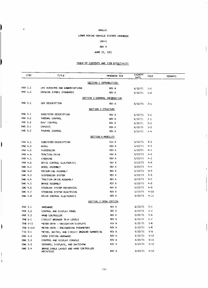
LUNAR ROVING VEHICLE SYSTEMS HANDBOOK
LRV-1
REV A
PREFACE I
Thi Spacecraf t Center , Houston, Texas. This document i s a complete r e i s s u e which r ep laces t h e Lunar Roving Vehlcle Systems Handbook, da ted March 29, 1971. Information contained w i t h i n t h i s document r e p r e s e n t s t h e lunar roving v e h i c l e systems as of June 22, 1971.
document has been prepared by t h e F l i g h t Control Div is ion , Manned
This document i s intended f o r spec ia l i zed use by t h e LRV f l i g h t c o n t r o l l e r s i n real-time and near-real- t ime ope ra t ions . This document, i n conjunct ion wi th t h e Boeing Company's LRV Operations Handbook , LS006-002-2H , w i l l p rovide t h e LRV f l i g h t c o n t r o l l e r s with a thorough knowledge of t h e LRV.
Comments r ega rd ing t h i s handbook should be d i r e c t e d t o t h e Lunar Surface Experiments Sec t ion of t h e Lunar/Earth Experiments Branch, F l i g h t Control Divis ion. Revis ions o r PCN's w i l l be i ssued as r equ i r ed p r i o r t o t h e f l i g h t da t e .
This document i s not t o be reproduced without t h e w r i t t e n approval of t h e Chief , F l i g h t Control Div is ion , Manned Spacecraf t Center , Houston, Texas.
I
Approved by :
Chief, F l i g h t Control Div is ion
ii
AWLLO
LUNAR RDVIN: VEHICLE SYSTEMS W B O O K
LRV-1
REV A
JUNE 22, 1971
TABLE OF CONTENTS AN) ITEM EFFECTIVITY
R W R K S SIGWFF PAGE DATE ITEM TITLE kV@BOOK WB
PAR 1.1
PAR 1.2
PAR 2.1
PAR 3.1
PAR 3.2
PAR 3.3
DWG 3.1
DWG 3.2
PAR 4.1
PAR 4.2
PAR 4.3
PAR 4.4
PAR 4.5
PAR 4.6
DWG 4.1
DWG 4.2
DWG 4.3
DWG 4.4
DWG 4.5
DWG 4.6
MJi 4.7
DWG 4.8
PAR 5.1
PAR 5.2
PAR 5.3
TAB 5-1
TAB 5-11
TAB 5-111
F I G 5-1
DWG 5.1
D f f i 5.2
DWG 5.3
D f f i 5.4
SECTION 1 INTROWCTION
LRV ACRONYMS AN) ABBREVIATIONS REV A
D W W I f f i SYMBOL STANMRDS REV A
SECTION 2 GENEPAL INFORMTION
LRV DESCRIPTION REV A
SECTION 3 STRUCTURE
SUBSYSTEM DESCRIPTION REV A
THERMAL CONTROL REV A
DUST CONTROL REV A
cH4ss IS REV A
THERMAL CONTROL REV A
SECTION 4 MDBILITY
SUBSYSTEM DESCRIPTION REV A
WHEEL REV A
SUSPENSION REV A
TRACTION DRIVE REV A
STEERIN; REV A
DRIVE CONTROL ELECTRONICS REV A
WHEEL ASSEMBLY REV A
DECOUPLIN; ASSEMBLY REV A
SUSPENSION SYSTEM REV A
TRACTION DRIVE ASSEMBLY REV A
BRAKE ASSEMBLY REV A
STEERIN; SYSTEM MECWINICAL REV A
STEERING SYSTEM ELECTRlCAL REV A
DRIVE CONTROL ELECTRONICS REV A
SECTION 5 CREW STATION
W D W E REV A
CONTROL AN) DISPLAY PANEL REV A
WN) CONTROLLER REV A
CIRCUIT BREAKER TRIP LEVELS REV A
METER DATA - WVIGATlDN DlSPLAYS REV A
METER DATA - Eff i INEERIN: PARAMETERS REV A
METER, SWITCH, AN, CIRCUIT BREAKER NUMBERING REV A
CREW STATION W D W E REV A
CONTROL AN) DISPLAY CDNSDLE REV A
SENSORS, DISPLAYS, AND SWITCHING REV A
BRAKE CABLE LAYWT AN) W CONTROLLER MECHI ELEC REV A
6 /22 /71
6 / 2 2 / 7 1
6 / 221 7 1
6 /22 /71
6 /22 /71
6 / 2 2 / 7 1
61 221 7 1
6 /22 /71
6 / 221 7 1
6 / 2 2 / 7 1
6 / 2 2 / 7 1
6 / 2 2 / 7 1
61 22/71
61 22/71
6 /22 /71
6 /22 /71
6 / 2 2 / 7 1
6 /22 /71
61 22/71
61 22/71
6 / 2 2 / 7 1
6 /22 /71
6 / 2 2 / 7 1
6 /22 /71
6 / 2 2 / 7 1
61221 71
61 221 7 1
6 / 2 2 / 7 1
6 / 2 2 / 7 1
6 / 2 2 / 7 1
61 22/71
6 /22 /71
6 /22 /71
1-1
1-2
2-1
3-1
3-1
3-2
3-3
3-4
4-1
4-1
4-1
4-1
4-2
4-3
4-4
4-5
4-6
4-7
4-8
4-9
4-10
4-11
5-1
5-2
5-6
5-7
5-8
5-8
5-9
5-10
5-11
5-12
5-13
i i i

LRV REV A
TABLE OF CONTENTS AN) ITEM EFFECTIVITY JUNE 2 2 . 1 9 7 1 (CONCLUDED)
R W R K S SIGNOFF PAGE DATE
ITEM TITLE W B O O K PUB
PAR 6 . 1
PAR 6 . 2
PAR 6.3
TAB 6-1
D K 6.1
D K 6 . 2 1
PAR 7 . 1
PAR 1.2
PAR 7 . 3 PAR 7 . 4
PAR 7 . 5
TAB 7-1
F I G 7-1
F I G 7-2
DK; 7 . 1
PAR 8 . 1
PAR 8 . 2
PAR 8 . 3
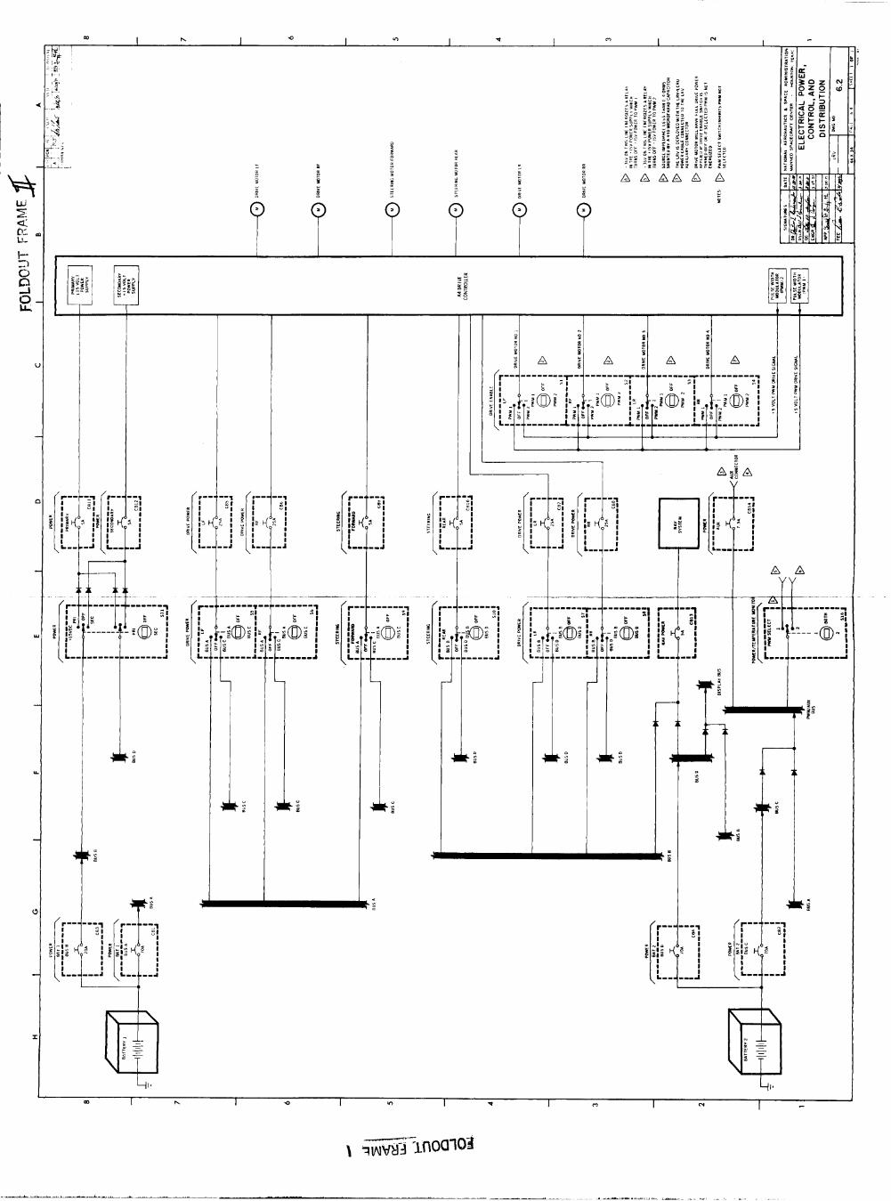
SECTION 6 ELECTRICAL POWER
GENERAL REV A
WTTERI ES REV A
DISTRIBUTION REV A
WTTERY DATA REV A
WTTERY REV A
ELECTRICAL POWER, CONTROL, AN) DISTRIBUTION REV A
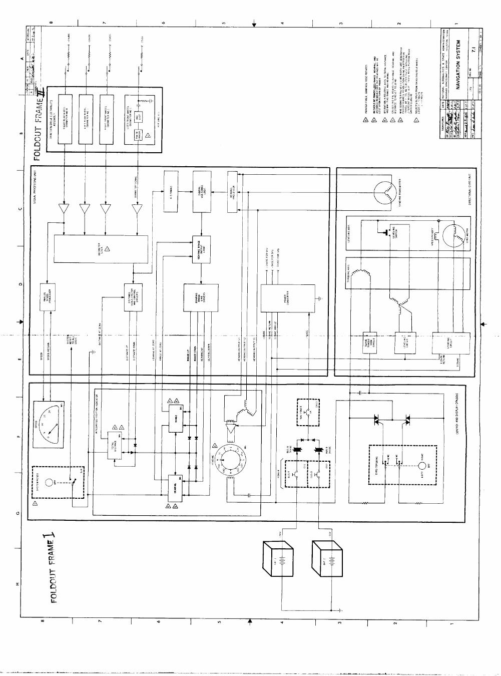
SECTION 7 NAVIGATION
GENERAL REV A
HEADIN; REV A
ODWETER REV A
RANGE AN) BEARING REV A
SUN S W W DEVICE REV A
POWER REQUIREMENTS REV A
NAVIGATION SUBSYSTEM BLOCK D I A G W REV A
M V IGAT I ON CMPONENTS REV A
NAVIGATION SYSTEM REV A
SECTION 8 EQUIPMENT STOWAGE
INTRODUCTION REV A
FORWRD CWSSIS PAYLOAD PROVISIONS REV A
CENTER CWSSIS PAYLOAD PROVISIONS REV A
6 / 2 2 / 7 1
61 2 217 1
6 / 2 2 / 7 1 61 2217 1
6 / 2 2 / 7 1
6 1 2 2 1 7 1
6 / 2 2 / 7 1
6 / 2 2 / 7 1
6 / 2 2 / 7 1
6 / 2 2 / 7 1
6 / 2 2 / 7 1
61 2 2 1 7 1
6 / 2 2 / 7 1
6 / 2 2 / 7 1
6 / 2 2 / 7 1
6 / 2 2 / 7 1
6 / 2 2 / 7 1
6 / 2 2 / 7 1
6-1
6-1
6- 1
6-2
6-3 6-4
7-1
7-1
7-1
7-2
7 - 2
7-2
7-3
7 -4 7 - 5
8 - 1
8-1
8 - 1
iv

SECTION 1 INTRODUCTION
LRV REV A
1.1 LRV ACRONYMS AND ABBREVIATIONS
ac Adc -P a n t assy
CB CDC
dC D E JXiU
F f l d fwd
gnd
HS
inh ib i n s u l IPI
i n s t l
km
LCRU
IM LRV
max mde MOCR
m s Msm
oper out
a l t e r n a t i n g current ampere(s) dc ampere( s 1 antenna assembly
c i r c u i t breaker cont ro l and display console
d i r e c t current d r i v e cont ro l e lec t ronics d i r e c t i o n a l gyro u n i t
fuse , Fahrenheit f i e l d forward
ground
h e a t s ink
i n h i b i t i n s u l a t i o n in tegra ted pos i t ion i n d i c a t o r i n s t allat ion
ki lometer( s)
lunar communications r e l a y u n i t lunar module lunar roving vehic le
maximum mode Mission Operat ions Control Room mill isecond Manned Space F l ight Network mobil i ty subsystem motor
not appl icable negat ive normal
operate output
percent por tab le l i f e support system p o s i t i v e pos i t ion primary pulse width modulator power .
ref reg r e v r l Y r s t
s c i si6 s n s r SPU
SUP SYS
T temp therm
V Vac Vdc
sw
W WH
reference regula tor reverse re lay r e s e t
s c i e n t i f i c s i g n a l sensor s igna l processing u n i t switch supply system
temperature temperature thermal
v o l t ( 8 ) v o l t ( s ) ac v o l t ( s ) dc
watt ( 8 1 walking hinge
1-1

LRV REV A
1 . 2 DRAWING SYMBOL STANDARDS
1.2.1 Line Legend
1 . 2 . 1 . 1 E l e c t r i c a l l i n e . power and control . -
A. E l e c t r i c a l connected + B. E l e c t r i c a l crossover
1.2.1.2 Direct ional flow arrows.- --- 1.2.1.3 Mechanical linkage.-
1-2
LRV REV A
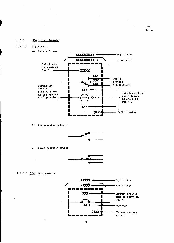
1.2.2 E l e c t r i c a l Symbols
1 .2 .2 .1 Switches.-
A. Switch format xxxxxxxxxx -Major t i t l e
/ ~XXXxxxxX &Minor t i t l e Switch name as shown on I
WXXXXX I Dvg 5 - 2 ,
Switch contact nomenclature
xxx
Switch pos i t ion nomenclature as shown on
I I
same pos i t ion I I
I I
L I I I I - I I
xxx 4-
Switch art (Shown i n
as t h e c i r c u i t configurat ion )
Dvg 5.2
I sxxf---- Switch number
B. Two-position switch:
C. Three-position switch
1.2.2.2 C i r c u i t breaker.-
1-3

LRV REV A
1.2.2.3 Battery.-
Name
1 .2 .2 .4 Relays.-
A . Latching r e l a y ,-<-’ 1 Latching contac ts
B. Non-latching re lay
Momentary contac ts --I I -
- -
1-4
LRV REV A
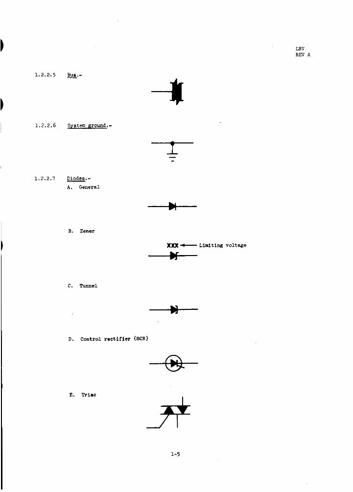
1.2.2.6 System ground.-
1.2.2.7 Diodes.- A. General
B . Zener
)O(X - Limiting voltage * C . Tunnel
* D. Control rect i f ier (SCR)
E. Triac
1-5

LRV REV A
1.2.2.8 Potentiometer .-
1.2.2.9 Reeistors .- A. Fixed
P
B. Thermistor or resistance thermometer (any element whose eensing resistance variee with temperature regardless of polarity)
1.2.2.10 Thermostat. -
1.2.2.11 Amplifier.-
Power input 6 output
Inverting input
Noninverting input
1-6

LRV REV A
1.2.2.12 Capacitors.- A . Fixed
B. Variable
1.2.2.13 Digital inverter.-
+ 1.2.2.14 Synchro transmitter. - I
1.2.2.15 Motor.-
I
1-7

LRV REV A
1.2.2.16 -.- A. And
8 A , - b Y
B. Nand
B
C. Or
B
D. Nor
B
E. Exclusive or
B
NOTE
Open circle indicates an inverter. -
1.2.2.17 Electrical filter.-
1.2.2.18 Transistors.-
A. NPN
Truth table
B. PNP
1-8

LRV REV A
1.2.3 Miscellaneous Symbols
1 .2 .3 .1 Drawing notes.- Notes a r e of two types: general and s p e c i f i c .
General notes do not apply t o a s p e c i f i c area on t h e drawing.
Spec i f ic notes do apply t o a s p e c i f i c area or a reas of t h e
drawing and are indicated with a note f l a g (shown below) which
appears i n t h e a rea o r a reas referenced.
1.2.3.2 Technical zone references.- Zone references d i r e c t a t t e n t i o n
from one a r e a t o another i n t h e same or another drawing.
The "2" shown below, with appropriate zone l o c a t o r s , ind ica tes
t h e exact area referenced.
X coordinate - A Z ~ - Y coordinate
xx .x
When t h i s number appears, it r e f e r s t o another drawing. When t h e r e i s no number, t h e zone r e f e r s t o another a rea on t h e same drawing.
i
The hexagon ("hex"), shown below, is used t o connect One l i n e t o another l i n e on t h e same o r on another
drawing.
"hex" t o d i r e c t a t t e n t i o n t o t h e loca t ion of t h e
corresponsing reference.
The appropriate "Z" appears next t o t h e
1-9
2.1
SECTION 2
GENERAL INFORMATION
LRV REV A
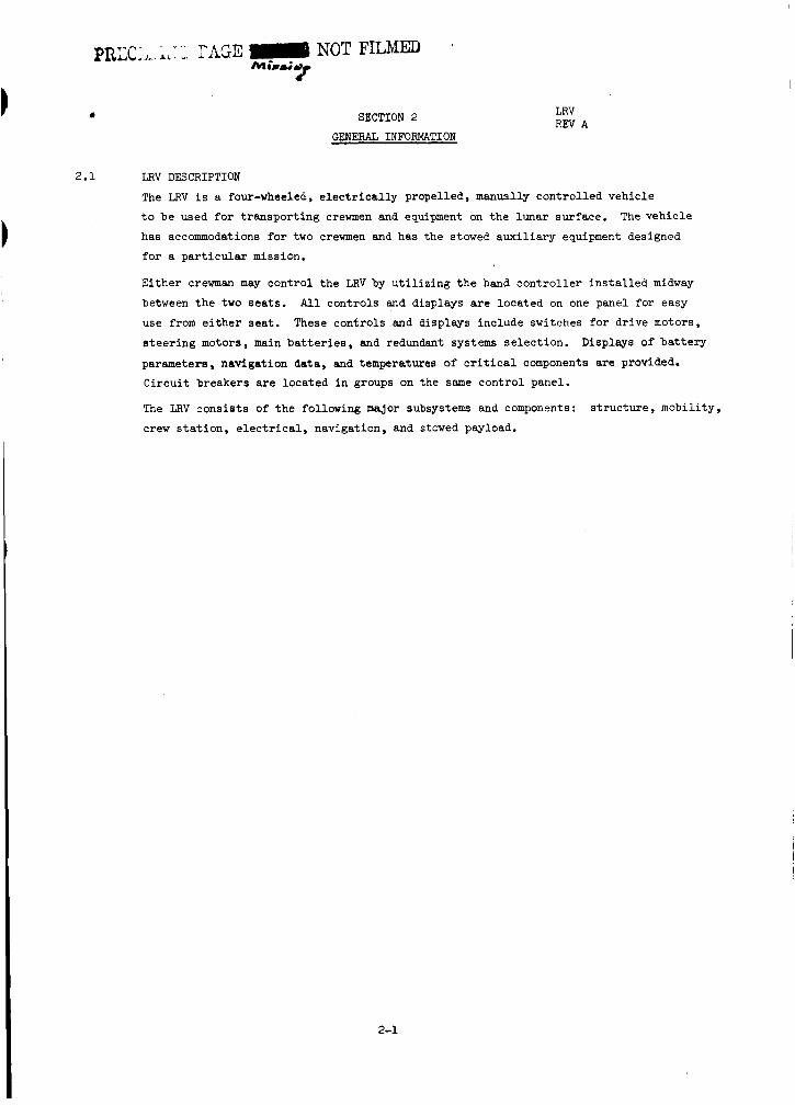
LRV DESCRIPTION
The LRV i s a four-wheeled, e l e c t r i c a l l y propelled, manuslly cont ro l led vehicle
t o be used f o r t ranspor t ing crewmen and equipment on t h e lunar surface.
has accommodations f o r two crewmen and has the stowed a u x i l i a r y equipment designed
f o r a p a r t i c u l a r mission.
E i t h e r crewman may cont ro l t h e LRV by u t i l i z i n g t h e hand c o n t r o l l e r i n s t a l l e d midway
between t h e two seats. All cont ro ls and displays a r e loca ted on one panel f o r easy
use from e i t h e r sea t . These cont ro ls and displays include switches f o r dr ive motors,
s t e e r i n g motors, main b a t t e r i e s , and redundant systems se lec t ion .
parameters, navigat ion data , and temperatures of c r i t i c a l components a r e provided. Ci rcu i t breakers a r e located i n groups on the same cont ro l panel.
The LRV cons is t s of t h e following major subsystems and components:
crew s t a t i o n , e l e c t r i c a l , navigation, and stowed payload.
The vehic le
Displays of ba t te ry
s t r u c t u r e , mobil i ty ,
2-1

*
3.1
3.2
3.2.1
3.2.2
3.2.2.1
3.2.2.2
SECTION 3 BTRUCTLJRE
LRV REV A
SUBSYSTEM DESCRIPTION
The LRV s t r u c t u r e subsystem cons is t s o f t h e chassis (Drawing 3.11, passive and a c t i v e
thermal cont ro l devices , and dust cont ro l devices.
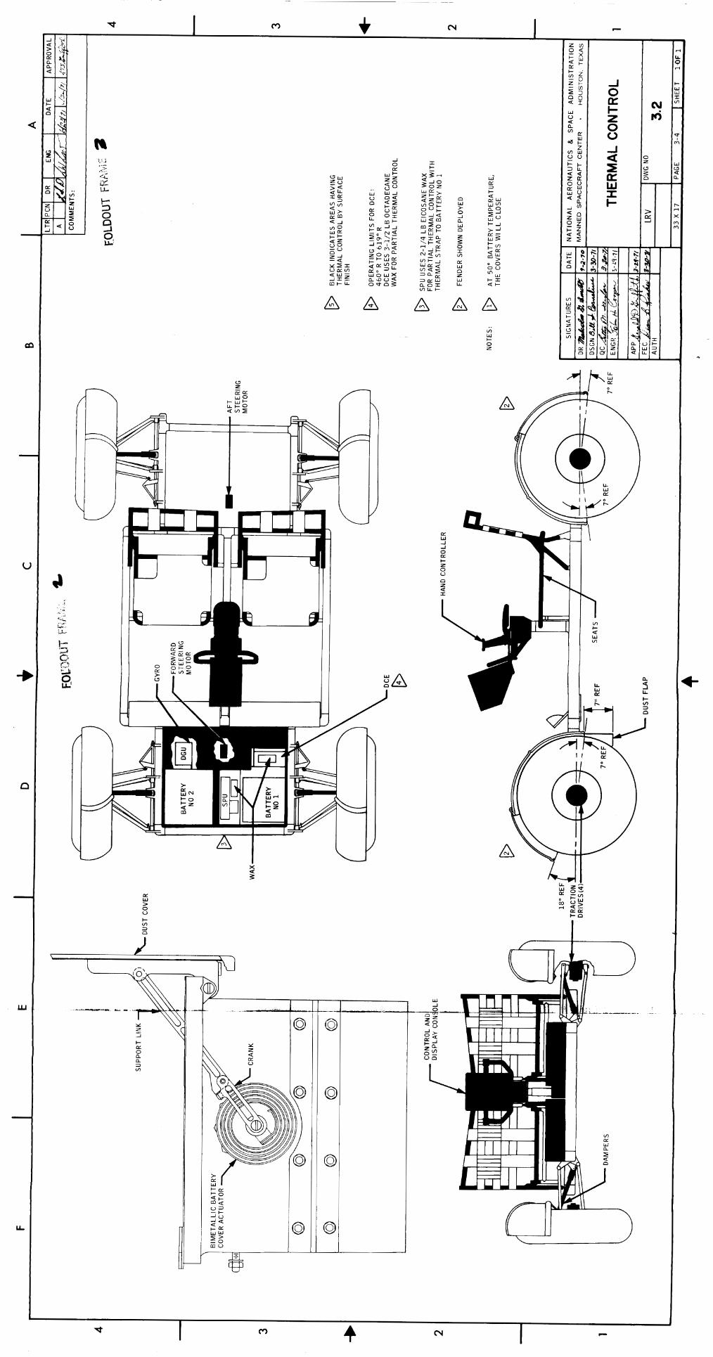
THERMAL CONTROL Thermal c o n t r o l (Drawing 3.2) is incorporated i n t o t h e LRV t o d i s s i p a t e excessive heat
from operat ing equipment i n the forward chassis , t o maintain operat ing l i m i t a t i o n s of
instruments on the cont ro l and d isp ley console, and t o r e l i e v e excessive heat from t h e
crew s t a t i o n . Thermal cont ro l is provided i n t h e forms of surface f i n i s h , insu la t ion ,
r a d i a t i v e sur faces , thermal mirrors, thermal s t raps , and f u s i b l e mas8 heat s inks.
A warning flag is provided t o ind ica te bat tery o r t r a c t i o n d r i v e overtemperatures.
Foward Chassis Thermal Control
Thermal cont ro l on t h e forward chass i s is provided by s t r a p s , thermal mir rors , thermal
blankets , f u s i b l e maes heat sinks, and dus t covers.
e l e c t r o n i c s (DCE) , s i g n a l processing u n i t (SF’U), d i r e c t i o n a l gyro uni t (DGU) and b a t t e r i e s
1 and 2 from overheating.
with 14 l a y e r s of in te rspersed nylon net .
Aluminum thermal s t r a p s connected t o t h e DCE, SPU, and DGU t r a n s f e r heat away from these
e l e c t r o n i c components and s t o r e it i n t h e b a t t e r i e s and/or t h e f u s i b l e mass heat s inks.
Fused s i l i c a thermal mirrors are incorporated on t o p of b a t t e r i e s 1 and 2, t h e SPU, and t h e
DCE and operate t o d i s s i p a t e heat f’rcm the b a t t e r i e s and f u s i b l e mass heat s inks when t h e
duet covers are opened.
Fiber-glass dus t covers over both b a t t e r i e s and t h e SPU are opened manually and c lose automatical ly by means of a bimeta l l ic c losing a c t u a t o r (Drawing 3.2).
linked with the b a t t e r y 1 cover, and, as such, will open and c lose at t h e same t i m e .
Temperature l i m i t s are described i n t h e subsystun descr ip t ions .
These pro tec t t h e dr ive cont ro l
Thermal blankets a re composed of 15 l ayers of aluminized mylar
The SPU cover is
Crew S t a t i o n Thermal Control
Control and d isp lay console (CDC).- A l l instruments on t h e CDC a r e mounted t o an
aluminum p l a t e which is i s o l a t e d by mult i layer i n s u l a t i o n and f iber -g lass mounts.
e x t e r n a l surfaces of t h e CDC are coated with heat r e s i s t a n t pa in t (Dow-Corning 92-0071,
and t h e f a c e p l a t e is black-anodized.
The
Center chassis.- Handholds, f o o t r e s t s , tubular sec t ions o f s e a t s , and center and aft
f l o o r panels are anodized.
3-1
*
I
LRV R E V A
3.3 DUST CONTROL
Dust cont ro l i s incorporated i n t o t h e LRV t o minimize t h e e f f e c t of lunar dust on t h e
equipment and crew.
s e a l s , and caps.
Fiber-glass fenders cont ro l t h e dust created by the wheels.
f ixed sec t ion and a s l i d i n g sec t ion which must be extended by t h e crew upon deployment
on t h e lunar surface.
A boot around t h e base of t h e hand c o n t r o l l e r g r i p provides cont ro l aga ins t dust en ter ing t h e mechanism.
The s t e e r i n g s e c t o r s in t h e forward and aft chass i s a r e enclosed with s t r u c t u r e ,
b e t a c l o t h , and boots fo r dust control .
All working j o i n t s of t h e suspension system a r e pro tec ted from dust by s e a l s and dust
caps.
The t r a c t i o n dr ive assemblies are hermetical ly sea led thus preventing en t ry of lunar
dust.
Dust cont ro l is provided by means of fenders, boots , covers,
The fenders cons is t of
Dust cont ro l f o r t h e brakes is provided by c i rcumferent ia l s h i e l d s around t h e drums
and boots around t h e brake levers .
The p is ton rod of t h e l i n e a r damper is protected from dust by a c y l i n d r i c a l s leeve
and by sea ls .
Fiber-glass cover6 over t h e b a t t e r i e s and SW provide dust pro tec t ion fo r t h e thermal
mirrors while closed.
3-2

0 JKl ?i
0
J O * i?
t-
I I..&
z 4
t- 3 0
0
E
9 LL
0
I - . mr-
01
a m -
f
I
W
-I W z 1 ; I d E
5 m m
E 0
L L 3
z V E W I- 2 W V
'? 01 0 rl w
-I m
n J
? W 0 I-
W W C
0
I - . v)b
d
a m - \ \
\I I I I I I
cl
1 z? I I
mnm r(
n w L C
0 O. rl
8 / 8 2 Y I
+ -1
I- v,
4 a
a >- c

m W I 2 z I -
A A A A m W I- O z
9 m cv c
c
8 J 0 D!
W' D! 3
a W I I-
I-
n W > 0 J
W a n
0
0 LL(
9 a 1
E W
z W LL
n 0 0 0 0
W m +I 6l-
A A A ALL ul
2 0 z
C
E W > 0 0
I I \
. -.
0
0
0
Y z 6
0 3 - -c
9 m cv c I I 4

LRV REV A * SECTION 4
MOBILITY
4.1 SUBSYSTEM DESCRIPTION
The LRV mobil i ty subsystem cons is t s of t h e wheels, suspension, t r a c t i o n dr ive , s t e e r i n g mechanical, s teer ing e l e c t r i c a l , and d r i v e cont ro l e lec t ronics .
4.2 WHEEL
Each wheel (Drawing 4 . 1 ) cons is t s of an open wire mesh, t i r e with chevron thread covering 50 percent of t h e surface contact area.
excessive def lec t ion of t h e outer wire mesh frame under high impact load condi t ions.
Each t i r e is capable of maintaining f u l l operations with 1 0 percent of t h e wire elements
broken.
The t i r e inner frame (bump s top) prevents
Each wheel can be uncoupled from t h e t r a c t i o n d r i v e by operat ion of t h e two decoupling mechanisms (Drawing 4.21, which allows t h e wheel t o "free-wheel" about a bearing sur face
independent of t h e dr ive t r a i n f o r up t o 100 Irm of lunar operat ion.
mechanism can a l s o be used t o re-engage t h e wheel with t h e t r a c t i o n dr ive .
outboard toehold can be used as t h e wheel decoupling t o o l .
i n a nonfunctional brake and odometer f o r t h a t wheel.
The decoupling
Ei ther
Decoupling a wheel r e s u l t s
4.3 SUSPENSION
The chass i s i s suspended from each wheel by a p a i r of p a r a l l e l t r i a n g u l a r arms connected
between t h e LRV chass i s and each t r a c t i o n drive.
system.)
t o r s i o n bar f o r each arm.
from t h e stowed condition. Deployed, they carry about 15 percent of each wheel load, with
t h e lower t o r s i o n bars carrying t h e remaining 85 percent . Wheel v e r t i c a l t r a v e l and r a t e
of t r a v e l i s l imi ted by a damper connection between t h e chass i s and each upper suspension
arm.
under nominal load condi t ions.
combines t o allow 1 4 inches of chassis ground clearance when t h e LRV i s f u l l y loaded and
17 inches when unloaded.
Damping energy hea t i s t r a n s f e r r e d t o t h e s i l i c o n e o i l (47 cc) i n t h e damper.
then conducted from t h e o i l t o t h e damper walls for diss ipa t ion .
The suspension assembly i s r o t a t a b l e approximately 135 degrees t o allow LRV stowage i n
t h e LM.
(See Drawing 4 . 3 f o r t h e suspension
Loads are t ransmit ted t o t h e chassis through each suspension arm t o a separate
The upper t o r s i o n bars a r e used pr imari ly t o deploy t h e wheels
The damper limits wheel v e r t i c a l t r a v e l t o 6 inches of jounce and 4 inches of rebound
The combination def lec t ion of t h e suspension system/t i res
The heat i s
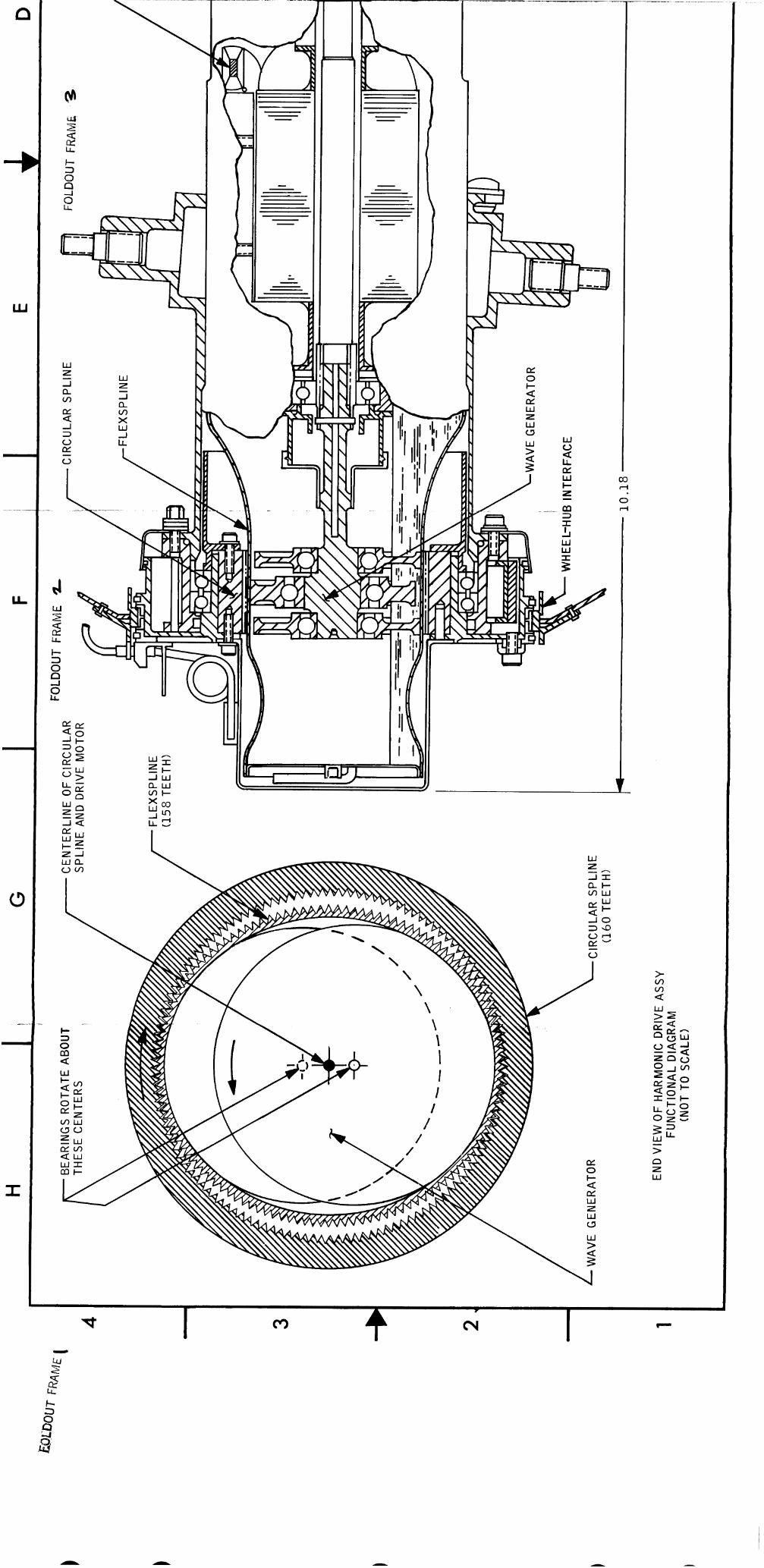
4.4 TRACTION DRIVE
Each wheel is provided with a separate t r a c t i o n d r i v e assembly (Drawing 4 .4) consis t ing
of harmonic d r i v e reduct ion u n i t , d r ive motor, and brake assembly. Each t r a c t i o n dr ive
i s hermet ica l ly sealed t o maintain a 7.5 p s i 8 i n t e r n a l pressure f o r optimum thermal control .
Decoupling a wheel a l s o decouples t h a t t r a c t i o n dr ive assembly.
4-1
e
4.4 .1
4.4.2
4.4.3
4.5
4.5 .1
LRV REV A
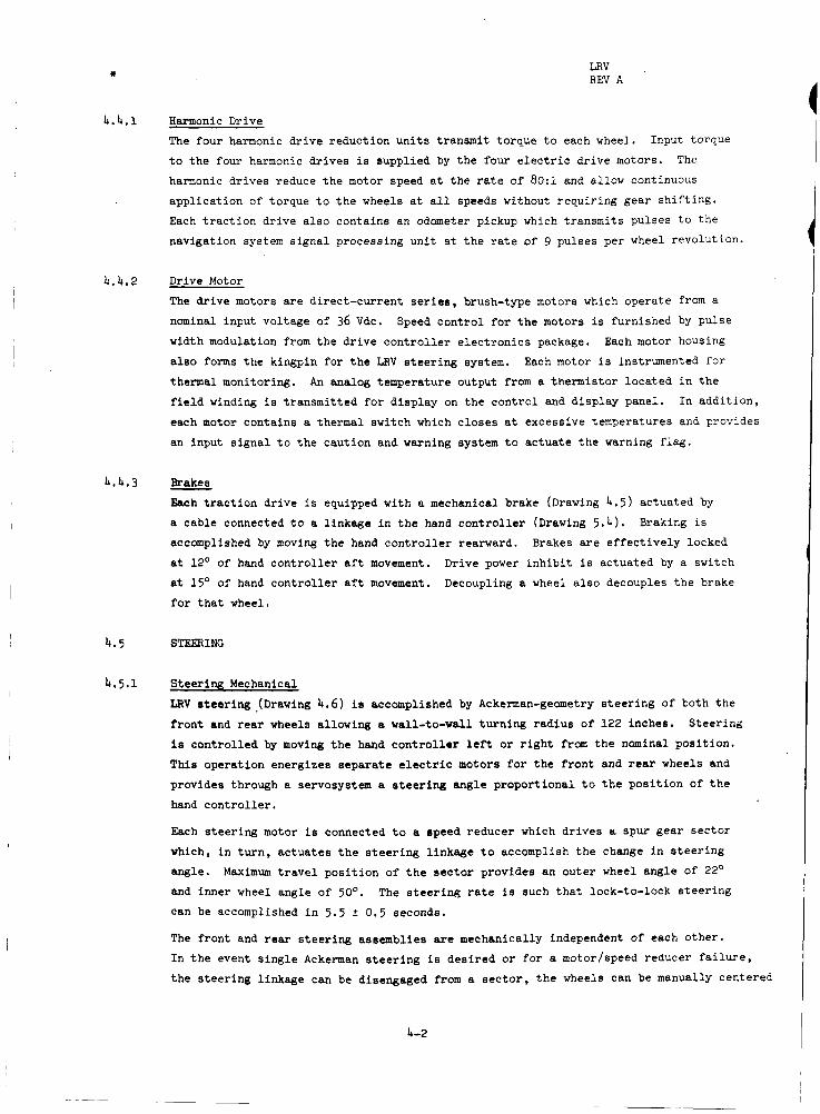
Harmonic Drive
The four harmonic d r i v e reduct ion u n i t s t ransmit torque t o each wheel. Input torque
t o t h e four harmonic dr ives i s suppl ied by t h e four e l e c t r i c dr ive motors. The
harmonic dr ives reduce t h e motor speed a t t h e r a t e of 8O:l and allow continuous
appl ica t ion of torque t o t h e wheels a t a l l speeds without requi r ing gear s h i f t i n g .
Each t r a c t i o n dr ive a l s o contains an odometer pickup which t ransmi ts pulses t o t h e
navigation system s igna l processing u n i t a t t h e r a t e of 9 pulses per wheel revolut ion.
Drive Motor
The dr ive motors a r e direct-current s e r i e s , brush-type motors which operate from a
nominal input vol tage of 36 Vdc.
width modulation from t h e d r i v e c o n t r o l l e r e l e c t r o n i c s package.
a l s o forms t h e kingpin f o r t h e LFN s t e e r i n g system.
thermal monitoring, f i e l d winding i s t ransmit ted f o r d i sp lay on t h e cont ro l and d isp lay panel. In addi t ion ,
each motor contains a thermal switch which c loses a t excessive temperatures and provides
an input s igna l t o t h e caut ion and warning system t o ac tua te t h e warning f lag .
Speed cont ro l fo r t h e motors i s furnished by Pulse
Each motor housing
Each motor i s instrumented f o r
An analog temperature output from a thermistor loca ted i n t h e
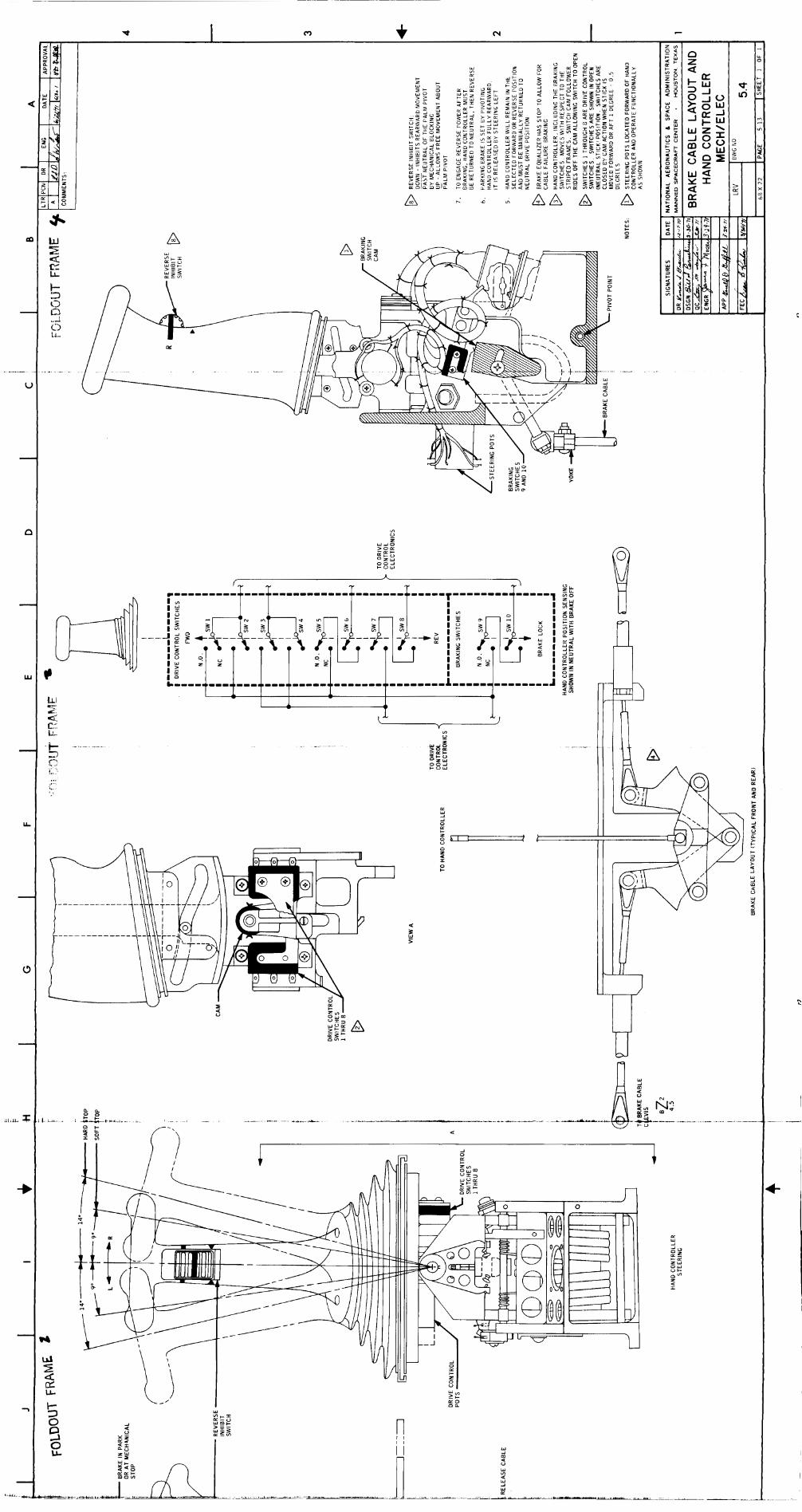
Brakes
Each t r a c t i o n dr ive i s equipped with a mechanical brake (Drawing 4 . 5 ) actuated by
a cable connected t o a l inkage i n t h e hand c o n t r o l l e r (Drawing 5.4) .
accomplished by moving t h e hand c o n t r o l l e r rearward. Brakes a r e e f f e c t i v e l y locked
a t 12' of hand c o n t r o l l e r a f t movement.
a t 15' of hand c o n t r o l l e r a f t movement.
f o r t h a t wheel.
Braking is
Drive power i n h i b i t is actuated by a switch
Decoupling a wheel a l s o decouples t h e brake
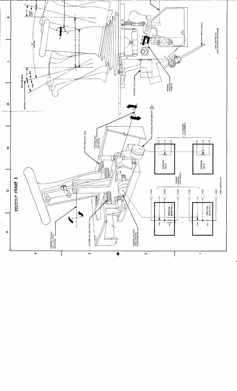
STEERING
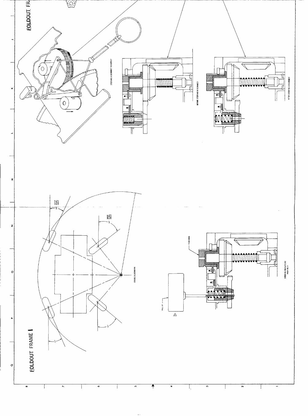
Steer ing Mechanical
LRV s t e e r i n g -(Drawing 4.6) is accomplished by Ackerman-geometry s t e e r i n g of both t h e
f r o n t and rear wheels allowing a wall-to-wall t u r n i n g rad ius o f 122 inches.
is cont ro l led by moving t h e hand c o n t r o l l e r l e f t o r r i g h t from t h e nominal pos i t ion .
This operat ion energizes separa te e l e c t r i c motors f o r t h e f r o n t and rear wheels and
provide6 through a servosystem a s t e e r i n g angle propor t iona l t o t h e p o s i t i o n of t h e
hand c o n t r o l l e r .
Each s teer ing motor is connected t o a speed reducer which dr ives a spur gear s e c t o r
which, i n t u r n , ac tua tes t h e s t e e r i n g l inkage t o accomplish t h e change i n s t e e r i n g
angle. Maximum t r a v e l p o s i t i o n of t h e s e c t o r provides an outer wheel angle of 22'
and inner wheel angle of 50'.
can be accomplished i n 5 .5 ? 0.5 seconds.
The f ront and r e a r s t e e r i n g assemblies are mechanically independent of each o ther .
In t h e event s i n g l e Ackerman s t e e r i n g i s d e s i r e d o r f o r a motor/speed reducer f a i l u r e ,
t h e s teer ing l inkage can be disengaged from a s e c t o r , t h e wheels can be manually centered
S teer ing
The s t e e r i n g rate is such t h a t lock-to-lock s t e e r i n g
4-2

LRV REV A
and locked, and operat ions can continue using t h e remaining a c t i v e s teer ing assembly.
Forward s t e e r i n g re-engagement cannot be accomplished by a crewman. The af t s t e e r i n g
can be re-engaged using t h e spec ia l t o o l stowed on t h e af t chassis . This t o o l i s used
t o r e t r a c t t h e locking p i n from t h e s teer ing s e c t o r .
4 .5 .2 Steer ing E l e c t r i c a l
The s t e e r i n g e l e c t r i c a l system (Drawing 4.7) i s a servosystem.
def lec t ion of t h e hand cont ro l le r i s coupled t o t h e input servoamplifier a s an e r r o r
s i g n a l across a bridge.
motor f i e l d c o i l s i n a d i r e c t i o n determined by p o l a r i t y of t h e input e r r o r s igna l
(determined by t h e d i rec t ion t h a t t h e hand c o n t r o l l e r i s def lec ted) .
is dr iven by t h e s teer ing motor t o a pos i t ion t h a t exact ly cancels t h e o r i g i n a l input
e r r o r s igna l by balancing t h e bridge.
remain constant u n t i l t h e hand c o n t r o l l e r i s moved t o a new posi t ion.
The two s t e e r i n g motors a r e supplied power through separate c i r c u i t breakers from
s e l e c t a b l e e l e c t r i c a l buses t o provide redundancy.
Single Ackerman s teer ing can be se lec ted by center ing t h e wheels and turn ing of f e i t h e r
a f t o r forward s teer ing power. This procedure may requi re occasional ly recenter ing
t h e disabled s t e e r i n g by turn ing on i t s drive power momentarily with t h e hand c o n t r o l l e r
i n t h e s t r a i g h t ahead pos i t ion .
A s i g n a l generated by
This e r r o r s igna l i s amplified and appl ied t o t h e s teer ing
The feedback pot
Angular displacement of t h e wheels w i l l then
4.6 DRIVE CONTROL ELECTRONICS (Drawing 4.8) A forward o r rearward motion of t h e hand cont ro l le r about t h e palm pivot point c loses
switches which s e l e c t forward or reverse drive d i rec t ion . This same movement causes a
s i g n a l t o be generated by t h e wiper of t h e t r a c t i o n dr ive pot .
t h e duty cyc le modulation of t h e pulse width modulator (PWM).
PWM i s proport ional t o t h e amount of hand cont ro l le r def lec t ion ( t h r o t t l e ) .
s i g n a l is then coupled through an i n h i b i t gate t o current- l imited power t r a n s i s t o r s
which i n ' t u r n modulate 36 Vdc power t o t h e drive motor f i e l d c o i l s .
c u r r e n t flow through t h e dr ive motor is determined by motor cont ro l re lays which a r e
normally cont ro l led by t h e hand c o n t r o l l e r se lec t switches.
S igna ls generated by t h e odometer reed switches i n t h e t r a c t i o n dr ive prevent
a p p l i c a t i o n of reverse dr ive motor power while moving forward o r vice-versa i f t h e
LRV speed i s g r e a t e r than 1 kin per hour. The vehic le should be completely stopped
before attempting t o change d i rec t ion as t h e odometer i n h i b i t s a r e unpredictable
between 1 Irm per hour and stopped.
Drive power i s a l s o inh ib i ted by a dr ive power i n h i b i t switch which c loses at t h e
hand c o n t r o l l e r a f t 15' pos i t ion (brakes nominally lock at 12' a f t ) or by g e t t i n g a c u r r e n t overload s i g n a l from t h e cur ren t l imi t ing c i r c u i t s .
temporar i ly inh ib i ted while changing d i rec t ions t o prevent switching t h e motor cont ro l
r e l a y s under load.
Applicat ion of motor dr ive power when applying brakes is possible s ince t h e brakes lock
at approximately 12' aft hand c o n t r o l l e r movcment, and t h e brake i n h i b i t l o g i c i s set a t 15' aft hand c o n t r o l l e r movement. This is t r u e f o r both forward and reverse dr ive
power.
This s i g n a l cont ro ls
The pulse width of t h e
This
The d i r e c t i o n of
Also, d r ive power is
k-3

I I I Q I v) + v I n I P( m h I
OD h Q v) v n 4
\ \

-
c3
1_ N
m d
'I
Y
a v) v)
I 0
04 4

u I- z 3 0 I
z
m 0 I- VI
a

/
cy 4 m

_I ,
m
\D L n d
v) f w v,
1 I
7 a z 0 I- o W v)
-
J
I 3
r
\
\ \ \ \ \ \
\ \ \ \ \
\

6
--
\
\
\ \
\
W
\ A

--
n
L
L L
I 1 rl I I I I I
I
U I- 0 2 0 Qf m Q I- w
CY w M M 3 Qf
U
I- O 0
I- m 3
CY w
m
n
m m 3 CY
>
I- v) - 0 a
I- 3 0 n
r

w Y
ct a a
c3 f cy
n J w I v) c
-
'4 1.. .
< - .
k 0
a 0 I-
v, W I 0
C n Z
.. W L
0 z
N: I
w J
0 w Y
E
m a
a a
W z - w 2 -I a - -I
a v, E a v,
X N 0 Qi
f) 0 L
E
J 3
a
LL 0
Qi 0
-

-lz a x d
.. U I- o z
W W E 0 3 v)+
W E o w z a
f
LJ

A A A v)
+ 8 1
I I I I I I I I
r---
I I l w l I K Z I
- J I 1 v ) I I I I I I I I I
L1~llllllll=lll k 11111111111 11
I I I I
I I I I
-1111111111 1111-1111 c r? i
> 0 4
+
V 0
Ln 4
+ z
I/) 0
z - 52 Y
4
c
-1 W
0
LI Y Y c v)
LI
Y LI a
w w
LL 4 Y LI
Y y
m
N
A
W
P
5 W
Y W
g U
A
n
I--, +--
T T

..
---------
I I I n 4 * I P) I N I c m h 0

I I I I I N B h 0 v) .c P 0
1
A A A A A I - E
.
- 1
I / I I J I I I
I I
T F"
I I %, I 2

* I SECTZON 5 LRV
REV A
5.1 HARDWARE
The crew s t a t i o n hardware cons is t s of seats, f o o t r e s t s , inboard handholds, outboard
handholds , armrest, f l o o r panels , s e a t b e l t s , fenders, and toeholds (Drawing 5 .1) .
5.1.1 Seats The two LRV seats are tubular aluminum frames spanned'by nylon. The s e a t s a r e folded
f la t onto t h e center chass i s f o r launch and a r e e rec ted by t h e crew after LRV deploy-
ment on t h e lunar surface.
l i f e support system (PLSS) from l a t e r a l motion when t h e crew members a r e seated.
s e a t e rec t ion sequence is shown on Drawing 5.1. t o allow t h e crew access t o the PLSS flow control valves and includes v e r t i c a l
supports f o r t h e PLSS.
The seat back i s used t o support and r e s t r a i n t h e portable
The
The seat bottom contains a cutout
A stowage beg is provided under each shee t .
5.1.2 Foot res t s
For launch, t h e footrests are stowed aga ins t the c e n t e r chass i s f l o o r where they a re
he ld by a Velcro pad.
and is adjus tab le prelaunch t o accommodate various s i z e crewmen.
The b a s i c f o o t r e s t i s deployed by the crew on t h e lunar surface
5.1.3 Inboard and Outboard Handholde
The inboard handholda are constructed o f 1-inch 0.d. aluminum tubing and are used t o
a i d t h e crew i n ingress of t h e LRV.
receptac les f o r t h e 16-prm data-acquisition c m e r a and t h e lunar communications re lay
u n i t (LCRU) low-gain antenna.
The outboard hsndholda are i n t e g r a l p a r t s of the chassis .
provide crew canfor t and s t a b i l i t y vhen reated on t h e LRV.
s e a t b c l t attachment.
These handholds a l s o contain i d e n t i c a l payload a t t a c h
These handholds a r e used t o
They a r e a l s o used f o r
5.1.4 Armrest The arnkert is used t o support t h e inboard ann of both crewmen when sea ted t o
prevent ann f a t i g u e and t o support t h e ann of t h e operator during hand c o n t r o l l e r
operat ion.
5.1.5 Floor Panels
The floor panels in t h e crew Etat ion area are beaded aluminum panels.
s t r u c t u r a l l y capable of rupporting t h e static Rill weight o f standing astronauts .
The f l o o r i s
5.1.6 S e a t b e l t s
Nylon vebbing reatbelts are provided for each seat. hook which i r used t o attach and remove the bel t t o t h e outboard handhold.
of t h e belt is aqlusted by a buckle.
i n the b e l t e l imina tes t h e necess i ty of b e l t length adjustments while fas tening or
r e l e a s i n g t h e b e l t .
The b e l t end terminates i n a Length
A spring-loaded s t r e t c h sec t ion (2.5-inch s t r e t c h )
5-1

* LRV REV A
5.1.7 Fenders The retractable portion of each fender is deployed by the astronaut during LRV activation on the lunar surface.
5.1.8 Outboard Toehold The outboard toeholds are used to aid the crew in egressing the LRV in one-sixth gravity operations. tripods.
as the toehold. secured with a ball pin to form the operational position of the toehold. tool used to decouple the wheel, to release the telescoping tubes and saddle fitting on the forward chassis, and to free the steering decoupling rings from the stowed position. Either toehold may be used as a tool.
Each toehold is formed by dismantling the left and right LRV/LM interface The leg previously pinned to the center chassis longitudinal member i s used
The tripod member is inserted into the chassis receptacle where it is It is a lso the
5.2 CONTROL AND DISPLAY PANEL
The control and display panel (Drawing 5.2) is separated into two functional parts: navigation on the upper part of the panel and monitoring/controls on the lower part. The function of each device on the panel is explained below.
5.2.1 Navigation Displays A. Attitude indicator - This instrument provides indications of LRV pitch and roll.
It indicates PITCH upslope (U) or downslope (D) within a range of plus 25 to minus 25 degrees in five-degree increments. The damper on the side of the indicator can be moved to the right in order to damp out oscillations. To read roll angles, the indicator is rotated forward which exposes the ROLL scale to the left-side crewman. The ROLL scale is graduated in one-degree increments 25 degrees either side of zero.
B. ' Integrated position indicator (IPI) - The IPI consists of the heading compass card, range- and bearing-to-1M digital indicators, and a total-distance-traveled indicator. The indicators are described individually.
HEADING (M6) - This compass rose indicator displays the LRV heading with respect to lunar north. plished by operating the GYRO TORQUING switch LEFT or RIGHT. calibrated in two-degree increments.
BEARING (M6) - This digital indicator displays bearing to the LM. reads in one-degree digits. navigation system, the BEARING indication will remain intact.
normal power may cause loss on the indications.
DISTANCE (M6) - This digital Indicator displays distance traveled bY the Mv in increments of 0.1 km.
Unit which, in turn, receives its inputs from the third-fastest traction-drive odometer.
C. The initial setting and updating of the heading indicator is accom-
The indicator is
D. This indicator
In the event of power loss or undervoltage to the Restoration of
E. This display is driven from the navigation signal processing
Total digital scale capacity is 99.9 km, Power loss will freeze the
5-2

I a LRV REV A
reading but r e s t o r a t i o n of normal power may cause t h e ind ica tor t o assume random
values.
RANGE (M6) - This d i g i t a l ind ica tor displays t h e d is tance t o t h e LM and, l i k e t h e
BEARING d isp lay , w i l l remain i n t a c t i n t h e event of power f a i l u r e with possible loss
of information a f t e r r e s t o r a t i o n of power. T o t a l ' d i g i t a l s c a l e capaci ty i s 99.9 km,
graduated on 0.1-km increments.
F.
NOTE - Operation i n reverse adds t o t h e dis- tance- t raveled display and w i l l b i a s t h e range and bearing values.
G. Sun shadow device - This device is used t o determine t h e LRV heading with respect
t o t h e sun. The s c a l e length is 15 degrees e i t h e r s i d e of zero with one-degree
d iv is ions .
SPEED (M5) - This ind ica tor shows LRV veloci ty from 0 t o 20 h / h r .
i s dr iven from t h e odometer pulses from t h e r i g h t r e a r wheel, through t h e SPU.
The sun shadow device can be u t i l i z e d a t sun angles up t o 75' ( z e n i t h ) .
H. This display
NOTE - There i e no speed ind ica t ion when t h e MAV POWER c i r c u i t breaker i s open o r the r i g h t rear wheel is decoupled.
5.2.2 Navigation Switches and Ci rcu i t Breaker
A. GYRO TORQUING (S15) - This switch is used t o slew t h e navigation gyro a t t h e r a t e of
1.5O/sec t o adJust t h e HEADING ind ica t ion during navigation updates.
switch i n LEFT moves t h e HEADING s c a l e clockwise. With t h e switch i n RIGHT, t h e s c a l e
r o t a t e s counterclockwise. There is a 2-minute torquing l i m i t with a 5-minute cooldown
period af terwards.
Placing t h e
This a l lova 180° of gyro torquing p e r cycle .
B. NAV POWER (CB13) - This c i r c u i t breaker is used t o r o u t e power from t h e main buses B
and D t o t h e navigation subsyrtem.
designed t o provide power fo r the navigation system from e i t h e r b a t t e r y simultaneously
t o preclude power l o s e i n t h e event of f a i l u r e of one ba t te ry .
breaker in the open pos i t ion , the SHI w i l l not funct ion, causing l o s s o f speed i n d i c a t i o n and allowing no ewer i n the navigation disp1s;ys.
m e r may cause t h e navigation d i rp lays t o MiUme r a n d m readings.
SYSTEM RESEl' (S14) - This switch i n used t o reset t h e BEARING, DISTANCE, and RANGE
d i g i t a l d i sp lays t o zero.
it i n t h e operat ing pos i t ion .
a c t u a t i o n of t h e switch.
The navigation and power d i s t r i b u t i o n system is
With t h i s c i r c u i t
Restoring navigation
C.
This switch requires pul l ing t h e toggle out , then placing This feature is designed t o prevent inadvertant
5.2.3 Power Sec t ion C i r c u i t Breakers and Switch
A . AUX (CB14) - This c i r c u i t breaker is used t o r o u t e power t o t h e a u x i l i a r y connector
a t t h e forward end of t h e LRV. This c i r c u i t breaker receives input power from
5-3

* LRV REV A
both b a t t e r i e s v i a buses A and C.
B. BAT 1 BUS A (CB1) - This c i r c u i t breaker is used t o energize bus A with power from b a t t e r y 1.
BAT 1 BUS B (CB3) - This c i r c u i t breaker i s used t o energize bus B with power from
b a t t e r y 1.
C .
D. BAT 2 BUS C (CB2) - This c i r c u i t breaker i s used t o energize bus C w i t h power from b a t t e r y 2.
E. BAT 2 BUS D (CB4) - This c i r c u i t breaker is used t o energize bus D with power from
b a t t e r y 2.
t 1 5 DC PRIM/OFF/SEC switch (S11) - This switch i s used t o route 36 Vdc power from
buses B and D t o t h e +15 DC PRIM ( C B 1 1 ) o r 215 DC SEC (CB12) c i r c u i t breakers.
215 DC PRIM ( C B 1 1 ) - This c i r c u i t breaker i s used t o route 36 Vdc power from t h e
215 DC PRIM/OFF/SEC switch t o t h e input of t h e primary t 1 5 v o l t dc power supply.
215 DC SEC (CB12) - This c i r c u i t breaker is used t o route 36 Vdc power from t h e
+15 DC PRIM/OFF/SEC switch t o t h e input of t h e secondary +15 v o l t dc power supply.
F.
G .
H.
5.2.4 Power/Temperature Monitor Switches and Mete=
A. AMP-HR meter ( M l ) - This double-scale i n d i c a t o r is used t o monitor remaining
b a t t e r y capacity i n b a t t e r y 1 and b a t t e r y 2.
"2" reading should be 121 amp-hrs.
A t f u l l charge, both t h e "1" and
These readings a r e not redundant.
B. VOLTS AMPS meter (M2) - This double-scale ind ica tor is used t o monitor t h e vol tage
o r current being supplied from b a t t e r y 1 and b a t t e r y 2 .
(vo l t s or amps) t o monitor i s cont ro l led by t h e BATTERY SELECT switch.
t h e same sca le f o r accurate cur ren t and vol tage, t h e s c a l e i s graduated from zero t o
100. When t h e VOLTS X 1 /2 pos i t ion of t h e BATTERY SELECT switch is se lec ted , t h e
meter ind ica t ion w i l l be twice t h e value of t h e a c t u a l b a t t e r y vol tage ( i . e . , t h e i n d i c a t o r W i l l read 72 f o r a vol tage of 36 Vdc a t t h e b a t t e r y ) .
o f b a t t e r y vol tages , 66 t o 82 (2X v o l t s ) , is bracketed on t h e sca le .
Select ion of which parameter In order t o use
The allowable excursion
C . MOTOR TEMP SELECT (S13) - This switch i s used t o s e l e c t t h e FORWARD o r REAR dr ive motor
temperature sensors t o be monitored on t h e MOTOR OF indica tor .
D. BATTERY SELECT (S12) - This switch is used t o s e l e c t e i t h e r vol tage or cur ren t of each
b a t t e r y on t h e VOLTS AMPS ind ica tor .
E. BATTERY OF meter (M3) - This double-scale i n d i c a t o r i s used t o monitor t h e i n t e r n a l
temperature of each ba t te ry .
meter.
The allowable b a t t e r y temperatures a r e bracketed on t h e
F. MOTOR O F meter ( M 4 ) - This double-scale i n d i c a t o r is used t o monitor t h e temperature
of each dr ive motor. E i ther t h e f r o n t or rear wheels a r e monitored a t any p a r t i c u l a r
time. Both l e f t and r i g h t wheels of e i t h e r t h e f r o n t o r r e a r set a r e monitored
5-4
LRV REV A
concurrently.
MOTOR TEMP SELECT switch t o e i t h e r FORWARD or REAR posi t ion.
temperatures are bracketed on t h e meter.
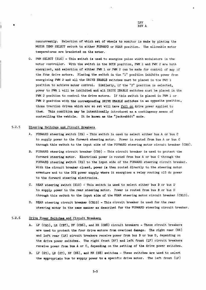
PWM SELECT ( ~ 1 6 ) - This switch i s used t o energize pulse width modulators i n t h e
motor c o n t r o l l e r .
energized, and s e l e c t i o n of e i t h e r PWM 1 or PWM 2 can be made f o r cont ro l of any of
t h e four d r i v e motors.
energizing PWM 2 and a l l t h e DRIVE ENABLE switches must be placed i n t h e PWM 1
pos i t ion t o achieve motor cont ro l .
power t o PWM 1 w i l l be i n h i b i t e d and a l l DRIVE ENABLE switches must be placed i n t h e
PWM 2 pos i t ion t o cont ro l t h e d r i v e motors.
€'wM 2 p o s i t i o n with t h e corresponding DRIVE ENABLE switches i n an opposi te p o s i t i o n ,
those t r a c t i o n dr ives which a r e so set w i l l have f u l l on d r i v e power appl ied t o
them. This condi t ion may be i n t e n t i o n a l l y introduced as a contingency means of cont ro l l ing t h e vehicle .
Select ion of which s e t of wheels t o monitor i s made by placing t h e
The allowable motor
G.
With t h e switch i n t h e BOTH poqi t ion , PWM 1 and PWM 2 a r e both
Placing t h e switch in t h e "1" pos i t ion i n h i b i t s power from
Similar ly , i f t h e "2" pos i t ion i s se lec ted ,
I f t h i s switch i s placed i n PWM 1 o r
It is known (LB t h e " jackrabbi t" mode.
5.2.5 Steer ing Switches and Ci rcu i t Breakers
A. FORWARD s t e e r i n g switch (S9) - This switch is used t o s e l e c t e i t h e r bus A or bus C
t o supply power t o t h e forward s t e e r i n g motor. Power i s routed from bus A or bus C
through t h i s switch t o t h e input s ide of t h e FORWARD s teer ing motor c i r c u i t breaker (CB9).
FORWARD s t e e r i n g c i r c u i t breaker (CB9) - This c i r c u i t breaker is used t o pro tec t t h e
forward s t e e r i n g motor.
FORWARD s t e e r i n g switch (Sg) t o t h e input s ide of t h e FORWARD s teer ing c i r c u i t breaker.
With t h e c i r c u i t breaker c losed, power i s then routed d i r e c t l y t o t h e s teer ing motor
armature and t o t h e DCE power supply where it energizes a r e l a y rout ing ?15 dc power
B. E l e c t r i c a l power i s routed from bus A or bus C through t h e
. t o t h e forward s teer ing e lec t ronics .
C. REAR s t e e r i n g switch (S10) - This switch i s used t o s e l e c t e i t h e r bus B o r bus D
t o supply power t o t h e rear s t e e r i n g motor. Power is routed from bus B o r bus D
through t h i s switch t o t h e input s i d e of t h e REAR s teer ing motor c i r c u i t breaker (CB10).
REAR s t e e r i n g c i r c u i t breaker (CB10) - This c i r c u i t breaker is used for t h e r e a r
s t e e r i n g motor i n t h e same manner ae described f o r t h e FORWARD s t e e r i n g c i r c u i t breaker.
D.
5.2.6 Drive Power Switchee and Ci rcu i t Breakers
A. LF (CB5), LR (CB7), RF (CB6), and RR ((238) c i r c u i t breakers - These c i r c u i t breakers
are used t o p r o t e c t t h e four d r i v e motors from overload damage. The r i g h t r e a r (RR)
and l e f t rear (LR) c i r c u i t breakers receive power from bus B or bus D , depending on
t h e d r i v e power switches. The r i g h t f r o n t (RF) and l e f t f r o n t (LF) c i r c u i t breakers
r e c e i v e power from bus A or C , depending on t h e s e t t i n g of t h e dr ive power switches.
LF (S5) , LR (s7), RF ( s 6 ) , and RR ( ~ 8 ) switches - These switches are used t o s e l e c t
t h e appropriate bus t o supply power t o a spec i f ic dr ive motor. The l e f t f ron t (LF)
B.
5-5
LRV REV A
and r i g h t f r o n t (Wr) d r i v e motors a r e powered from bus A when t h e LF and RF switches
are i n t h e BUS A pos i t ion .
and r i g h t f r o n t motors a r e suppl ied power from bus C.
switch prevents power from reaching t h e dr ive power c i r c u i t breakers .
motors a r e s i m i l a r l y powered by s e l e c t i n g t h e BUS B, BUS D , o r OFF pos i t ions of the
switches. These switches a l s o energize a r e l a y i n t h e DCE which appl ies k15 Vdc
power to t h e se lec ted e lec t ronics .
With t h e switches i n t h e BUS C p o s i t i o n , t h e l e f t f r o n t
I n t h e O F F p o s i t i o n , t h e
The r e a r dr ive
5.2.7 Drive Enable Switches
LF (Sl), L8 (S3), RF (S2) , and RR (Sh) switches - These switches a r e used t o s e l e c t e i t h e r
pulse width modulator 1 or 2 f o r cont ro l of a s p e c i f i c dr ive motor.
t h e PWM 1 pos i t ion , pulse width modulator 1 w i l l be used t o cont ro l t h e dr ive motor of t h e
appropriate switch ( i .e . , l e f t r e a r , r i g h t rear, l e f t f r o n t , or r i g h t f r o n t ) .
p o s i t i o n , f u l l d r ive power i s continuously appl ied t o t h e appl icable dr ive motor.
"OFF" pos i t ion should only be used during contingency modes of operat ion.
have guards placed around them. This i s a second method of configuring t h e contingency
" jackrabbi t" mode (see Paragraph 5.2.4.G).
With any switch i n
In t h e OFF
Thus, t h e
These switches
5.2.0 Caution and Warning System
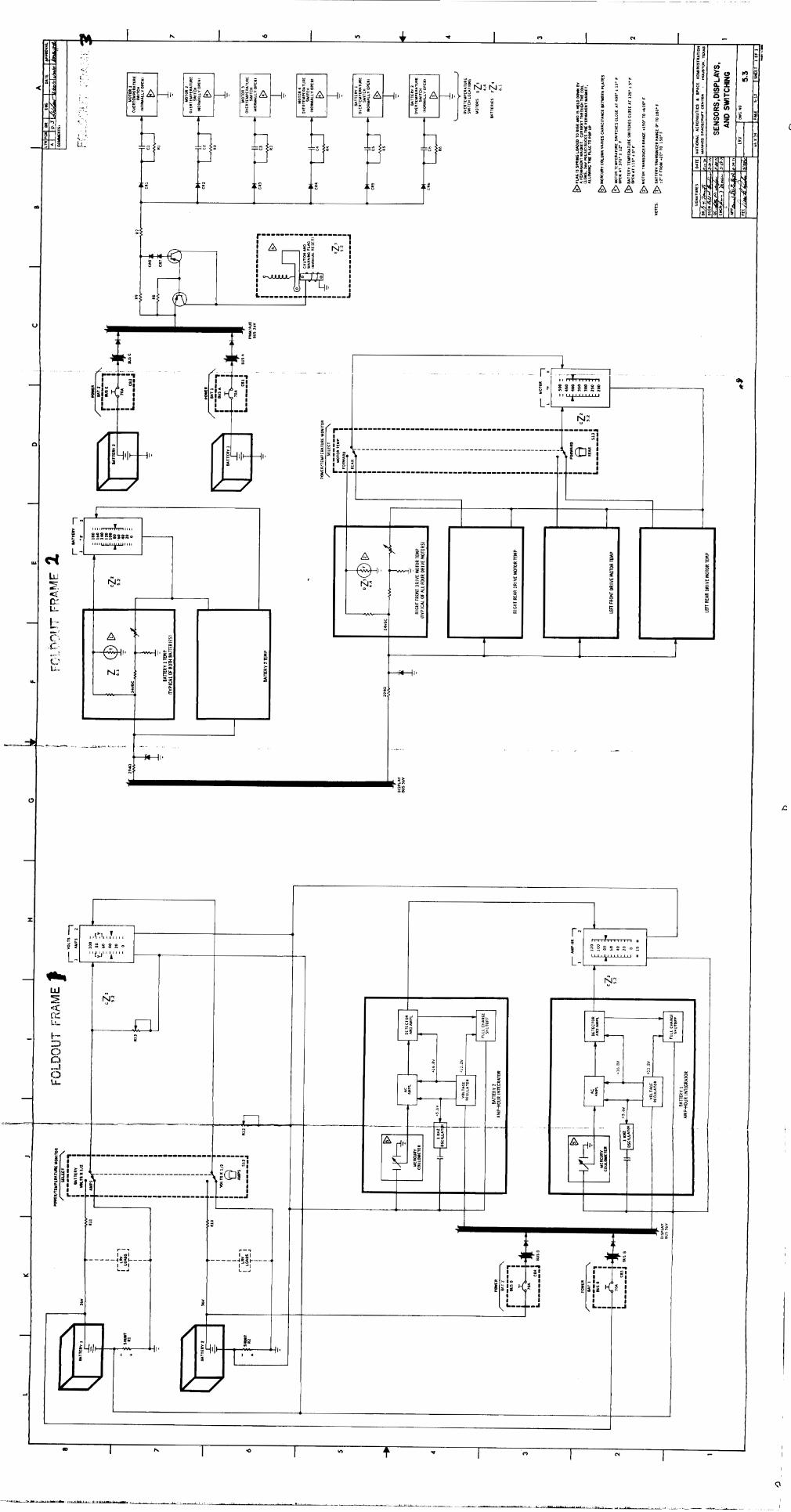
The caution and warning system i s shown schematically as an e n t i t y i n Drawing 5.3. The
normally open temperature switches i n t h e b a t t e r i e s and dr ive motors c lose on increasing
temperatures.
400 i 12' F , t h e temperature switch c loses , energizing t h e OR log ic element and t h e d r i v e r .
The d r i v e r then sends a 10-millisecond, 36-V pulse t o the c o i l of t h e electromagnet which
re leases t h e magnetic hold on t h e ind ica tor a t t h e t o p of t h e console and a spring-loaded
f l a g f l i p s up. The astronaut r e s e t s t h e flag by pushing it down.
When e i t h e r b a t t e r y reaches 125 k 5O F or any d r i v e motor reaches
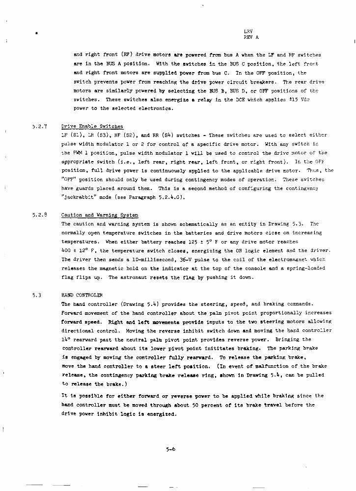
5.3 HAND CONTROLER
The hand c o n t r o l l e r (Drawing 5.4) provides t h e s t e e r i n g , speed, and braking commands.
Forward movement of t h e hand c o n t r o l l e r about t h e palm pivot point proport ional ly increases forward speed. Right and l e f t movements provide inputs t o t h e two s t e e r i n g motors allowing
d i r e c t i o n a l control . Moving t h e reverse i n h i b i t switch down and moving t h e hand c o n t r o l l e r
1b0 rearward pas t t h e n e u t r a l palm pivot point provides reverse power.
c o n t r o l l e r rearward about i t s lower p i v o t po in t i n i t i t a t e s braking.
i s engaged by moving t h e c o n t r o l l e r hrlly reward.
move t h e hand c o n t r o l l e r t o a steer l e f t p o i i t i o n .
r e l e a s e , t h e contingency parking brake release r i n g , shown i n Drawing 5 .4 , can be pul led
t o re lease t h e brake. )
It is poss ib le t o r e i t h e r forward or reverse power t o be appl ied while braking s ince t h e
hand c o n t r o l l e r must be moved through about 50 percent of i t s brake trawl before t h e dr ive power i n h i b i t l o g i c i s energized.
Bringing t h e
The parking brake
To release t h e parking brake,
( I n event of malfunction of t h e brake
5-6
CB
2B1
2B2
2B3
2B4
EB5
CB6
CB7 CB8
CB9 CBlO
C B l l
CB12
CB13
CB14
Nom amp
70
25
5
7.5
O°F
64.0
36.3
7.4
11.1
+77OF
73.5
28.75
5475
8.63
LRV REV A
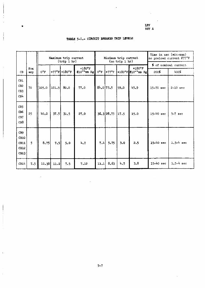
TABLE 5-1.- CIRCUIT BREAXER TRIP LEVEIS
Time i n sec (min-max) o preload current 877OF M a x i m u m t r i p cur ren t
( t r i p 1 hr) Minimum t r i p cur ren t
(no t r i p 1 hr) ;X of nominal cur ren t -
0 O F -
05.0
-
40.0
-
8.75
- 12.38 -
+180°F @10'4m He
+180°F i10-4m H(
~~
200% 4008
77.0 45.9 15-70 sec 2-10 sec
15-40 sec 27.0 15.0 3-7 sec
4.7 15-40 sec 1.5-4 sec 3.0
- 4.5 -
2.5
3.8 15-40 see 1.5-4 sec 7.12
5-7

LRY REV A
Headinga
Bearing t o LMa
Range t o LM Tota l dis tance t rave led
Velocity
Sun angle
Att i tude
P i tch
Rol l
TABLE 5-11.- METER DATA - NAVIGATION DISPLAYS
+ 6 O o t o 360' 1 degree
+ 6 O 0 t o 360' ' 1 degree
600 m at 5 km 0 .1 km
2% 0 t o 99 km 0.1 km
1 . 5 k d h r 0 t o 20 km/hr 1 km/hr
0 t o 30 km
f20 f15' lo
+25O 5 O 230
220 f25O lo
Data displayed
Units of Display Display me as u r emen t range reso lu t ion Meter
Amp-hour meter Amp-hoWS -15 t o +120 A-h 10 A-h
Volts-amps meter Volts: 0 t o 100 v 10 v
Amps : 0 t o 100 A 10 A
(divided by 2) (divided by 2 )
0 t o 180° F 20' F
200 t o 500' F 50' F
Battery temp Degrees meter Fahrenheit
Drive motor Degrees temp meter Fahrenheit
System Display Display 30 accuracy reso lu t ion 1
Meter accuracyb
2.8% iull s c d e
2.8% full s c a l e
2.8% f u l l s c a l e
2.8% iull s c a l e
2.8% iull s c a l e
8Ref t o lunar north
TABLE 5-111.- METER DATA - E N G I N E E R I N G PARAMETERS
5-8

LRV REV A
C B 1 4
0 C B 1
0
0
0
C B 3
C B 2
CB4
0 C B 1 1
C B 1 2 0 0
s11
0
M5 515 514
0 0 M 1 M2 M3 M4
513
0
0 512
S 9 CB9
00 S 1 0 C B l O
00
CB5 CB6 S5 S 6
0000 CB7 CB8 S7 S 8
0000
516
0
s 1 s2
00 s3 s4
00
Figure 5-1. - Meter, switch, and circuit breaker numbering.
5-9

c
-
I
h 3 8 g;
c m W CT I- O 0 LL
m I C O m o w > C T Wl- Z O 00 I L L
d c9 (Y c I I 4

c
W a
a a
r" Q
I z 0 I- d I- v)
-
L
3 w Qz 0
N vi
m W I- O z
vi !- E W VI z z 0 -I U W t-
E m m a I
1
L
r >
-+ - U
W c ln
a
m W + m
a
W 0
3 0 w v, L
5
z Y 2
c
@L w
w v,
w n c w v, a
m 2
c w w a m r n w a r n m m a I
I I
.--I -1
I I
I I
P w - > 0
O!- C.ia v a A E W e > m
z a a c
OL 0 >
w

iu z u U
L I
I u'
w -1
I W >
u
1 I
. . . _I r c. w
3 LL'
I u
5 w J
L n
4 W W +
(3
-1 LL
a
B n a z 0
m 4 I-
-
c

c
r n N 4
v) W I- O z
- - FNI I
a m
m m m m a 3
I V I= a n 0 LL V J w >
C W
- W
w J 5 2 q &
w o n -
P
t-
4 c
I
I' B
_-. I.
I I
I
I I .o I n t P I c) I PI I - OD h
--
i
% w
[L W J
0
- K
Y K
0
d I-
n IL
2 4
>
I- 3 0
4
W J
4 U
W Y
LL
u t
m
4
2 W Ps Z W O W V C
n"'
U I
I-
* SECTION 6 ELECTRICAL POWER
LRV RE?I A
6.1 GENERAL
The e l e c t r i c a l power subsystem cons is t s of two b a t t e r i e s and d i s t r i b u t i o n wiring,
connectors, switches, c i r c u i t breakers , and meters f o r cont ro l l ing and monitoring
e l e c t r i c a l power.
6.2 BATTERIES
The LRV contains two primary s i lver-zinc b a t t e r i e s (Drawing 6.1). a r e used simultaneously on an approximate-equal-load b a s i s during LRV operation
by s e l e c t i o n of various load-to-bus ccmbinations through c i r c u i t breakers and
switches on t h e cont ro l d i sp lay console.
The b a t t e r i e s are loca ted on t h e forward chassis enclosed by t h e thermal blanket
and dust covers.
t o t h e navigat ion s i g n a l processing u n i t and serves as a p a r t i a l heat s ink f o r t h e
SPU. gyro u n i t and nerves as a hea t sink for t h e NU.
The b a t t e r i e s are i n s t a l l e d i n t h e LRV on t h e pad at Kennedy Space Center i n an
a c t i v a t e d condition and are monitored f o r voltage and temperature on t h e ground u n t i l
T-18 hours i n t h e countdown.
remaining eq-hours, temperature, vol tage, end output current .
Each b a t t e r y is capable of carrying t h e e n t i r e LRV e l e c t r i c a l load, and t h e c i r -
c u i t r y is designed such t h a t i n t h e event one b a t t e r y fa i l s t h e e n t i r e e l e c t r i c a l
load can be switched t o t h e remaining ba t te ry .
Both b a t t e r i e s
Bat tery 1 (on t h e l e f t s i d e facing forward) is connected thermally
Bat tery 2 (on t h e right s i d e facing forward) is thermally t i e d t o t h e d i r e c t i o n a l
On t h e lunar surface, t h e b a t t e r i e s a re monitored for
6.3 DISTRIBUTION SYSTEM The e l e c t r i c a l schematic f o r t h e LRV is shown i n Drawing 6.2.
c i r , c u i t breaker arrangement is designed t o a l l o w switching any e l e c t r i c a l load t o
e i t h e r b a t t e r y . During normal LRV operat ion, t h e navigation system power must remain on during t h e
e n t i r e s o r t i e .
s t e e r i n g motors, dr ive cont ro l e lec t ronics , and *15 Vdc power suppl iee) may be turned
off at a stop.
The switch and
To conserve power, a l l mobility elements ( i .e, t r a c t i o n dr ives ,
6-1

LRV REV A
Voltage :
Current :
Capacity:
Thermal d iss ipa t ion :
Personnel sa fe ty :
TABLE 6-1.- BATTERY DATA
Nominal 361; Vdc, Transient 361; Vdc
47 A, max peaks t o 90 A
1 2 1 amp-hours (4356 watt-hours) a t 36 Vdc nominal 115 amp-hours (4140 watt-hours) a t 36 Vdc minimum High thermal conductance between c e l l block8 and surfaces of b a t t e r y case
Pressure r e l i e f valve opens at 3.1 t o 7 p s i d , c loses when d i f f e r e n t i a l pressure i s below valve 's r e l i e f pressure
Case designed t o withstand 9 p s i (without deformation)
6-2

c
m z W
0 a
m J J W V m 01
m m W J Z 3 W O
> m Ja a >r'
m
a A N . : m W t- 0 z
m W
X t- a 0-
c *n z g
-1 -I W 0
k W t- I-
m V
N !x W > m
a
5
=!
I- z J
W m
a a
c3 3 J
J
L L
a
i
?-I-
? : : ?
VI 0 m
.. . I *I
C
0
C
C
C
C
0
Q
3 0 0 1 0 0 0 -I L
I c A
---4
1 L L 1
--i

* SECTION 7
NAVIGATION
LRV REV A
7 .1 GENERAL
A block diagrem of t h e navigation subsystem i s shown i n Figure 7-1.
loca t ions are shown i n Figure 7-2.
The power supply converts t h e LRV b a t t e r y voltage t o t h e ac and dc vol tages required
f o r operat ion of t h e navigation subsystem components. Signal inputs t o t h e sub-
system are heading with respect t o lunar north (which i s obtained from a d i r e c t i o n a l
gyro) and odometer pulses corresponding t o a f ixed d is tance (which a r e obtained from
each t r a c t i o n d r i v e u n i t ) .
Hardware
These s i g n a l s a r e operated upon by t h e navigation subsystem which displays t h e r e s u l t s
as bear ing back t o t h e W, range back t o t h e LM, t o t a l d i s tance t rave led , and ve loc i ty .
The heading with respec t t o lunar north i s displayed d i r e c t l y .
7.2 HEADING
The d i r e c t i o n a l gyro is erec ted (case leveled) and torqued u n t i l it i s al igned with
l u n a r north. p i t c h and r o l l using t h e a t t i t u d e ind ica tor (Drawing 5.2) and t h e sun angle using t h e
sun shadow device (Drawing 5.2).
angle is calculated.
t h e ca lcu la ted value.
a 5-minute cooldown period following.
cycle .
d i g i t a l d i sp lays and i n t e r n a l r e g i s t e r s t o zero.
start of each t raverse .
The heading angle of t h e LRV is derived d i r e c t l y from t h e output of t h e gyro, which is
generated by a three-wire synchro t ransmi t te r and i s independent of computed data . The
heading i n d i c a t o r i n t h e in tegra ted pos i t ion ind ica tor ( I P I ) contains a synchro cont ro l
t ransformer and an electromechanical servosystem which dr ives t h e cont ro l transformer
u n t i l a n u l l is achieved with t h e inputs from t h e gyro.
Alignment is accomplished by measuring t h e i n c l i n a t i o n of t h e LRV i n
This in fomat ion is relayed t o e a r t h where a heading
The crew then torques the rryro u n t i l t h e heading ind ica tor matches
Gyro torquing can only be done continuously f o r 2 minutes with
This enables up t o 180' azimuth change per The system is i n i t i a l i z e d by using the SYSTEM RESET switch, which r e s e t s a l l
I n i t i a l i z a t i o n is performed at t h e
7 . 3 ODOMETER
There are f o u r odometers i n t h e system, one f o r each t r a c t i o n dr ive u n i t .
odometer pu lses are generated for each revolut ion of each wheel.
amplif ied and shaped i n the motor cont ro l le r c i r c u i t r y m d e n t e r t h e l i n e rece iver
i n t h e SPU. The odometer pulses from only t h e r i g h t rear wheel e n t e r t h e ve loc i ty
processor f o r d i sp lay on t h e M V SPEED indicator .
Odometer pu lses from a l l four wheels e n t e r t h e odometer l o g i c v i a t h e SPU l i n e
receivers. This l o g i c s e l e c t s t h e th i rd- fas tes t wheel f o r use i n t h e d is tance
computation.
wheel which i s locked, nor w i l l they be based on a wheel t h a t i s spinning.
NOTE The odometer l o g i c cannot d i s t inguish between forward and reverse wheel ro ta t ion . Therefore, reverse operat ion of t h e LRV adds t o the odometer reading.
Nine
These s igna ls a r e
This insures t h a t t h e odometer output pulses w i l l not be based on a
-
7-1
LRV REV A
The SPU odometer l o g i c sends outputs d i r e c t l y t o t h e d i g i t a l d i s tance i n d i c a t o r i n
t h e IPI and t o t h e range/bearing processor i n t h e SPU.
bearing processor , t h e outputs i n i t i a t e holding se lec t ion and conversion of heading
s i n e and cosine t o d i g i t a l numbers.
ind ica tor t o assume a random value upon resuming normal (>30 v o l t s ) voltaue.
Upon enter ing t h e rangel
Low vol tages (e30 v o l t s ) can cause t h e d is tance
7.4 RANGE AND BEARING
The e f f e c t of conversion of heading s i n e and cosine a t d is tance increments i s
equivalent t o enter ing d is tance increment times s i n e heading and d is tance increment
times cosine heading i n t o t h e AE and AN r e g i s t e r s i n t h e d i g i t a l p a r t of t h e bear ina
and range processor.
t h e components of t h e east ( E ) and north ( N ) accumulators. The E and N a c c m u l a t o r s , therefore , contain t h e east and north vector ccnnponents of t h e range and bear ing back
t o t h e LM. E numbers t o obta in range and bear ing, which are displayed on d i g i t a l counters i n t h e
IPI . Each d is tance increment from t h e odometer l o g i c i n i t i a t e s t h e e n t i r e sequence
described, and r e s u l t s i n t h e updating of bearing and range.
displays w i l l be re ta ined i n t h e event navigation system power i s l e s s than 30 v o l t s ,
but may be l o s t upon r e t u r n of normal power.
The d i g i t a l processor then adds t h e new AE and A N numbers t o
The d i g i t a l vector ing process then does a vector conversion on t h e N and
Range and bear ing
7.5 SUN SHADOW DEVICE The sun shadow device i s used t o determine LRV heading with respec t t o t h e sun.
length is 1 5 degrees e i t h e r s i d e of zero i n one-degree increments.
device can be used a t sun e leva t ion angles up t o 75'.
Scale
The sun shadow
TABLE 7-1.- POWEA REQUIR-S
I n i t i a l i z a t i o n and warmup (1.5 minutes m a x from c los ing of navigation CB) . . . . . . . . . . . . . . . . . . . . . . . . . 92 w a t t s
Operating: X U . . . . . . . . . . . . . . . . . . . 12 w a t t s
SPU . . . . . . . . . . . . . . . . . . . 28 Display e l e c t r o n i c s . . . . . . . . . . . 5 T o t a l . . . . . . . . . . . . . . . . . . . . . . . . . 4 5 w a t t s
7-2

+ rn 0 1 - 2
LRV REV A
4 d I
1
d I
t- aJ 3 L
7 -3

LRV REV A
Sun =-\ indicator Atti tude
Integrated position
indicator
Figure 7 - 2 . - Navigation components.
7 -4
[ = z -0 10 Y O
-r ... ..
- -
r L I
I L
t N - 0 10 9 0 0 h

I * SECTION 8
EQ- STOWAGE
LRV REY A
8.1 INTRODUCTION
This s e c t i o n contains t h e LRV auxi l ia ry equipment which includes provisions f o r
t ranspor t ing miscellaneous equipment f o r support of lunar a c t i v i t i e s , including
experiments, communications, and photography. Detailed stowage provis ions can be
found i n t h e Apollo 15 Lunar Roving Vehicle (LRV), Lunar Surface Equipment Stowage
Location and C r i t e r i a , MSC-03991 Revision A , dated Apri l 15, 1971.
8.2 FORWARD CHASSIS PAYLOAD PROVISIONS
The LRV forward chassis contains t h e equipment necessary t o t ranspor t t h e lunar
communications r e l a y u n i t (LCRU), t h e high-gain antenna, and t h e co lor TV camera
with remote command azimuth-elevation cont ro l un i t .
8.2.1 Lunar Connnunications Relay Unit
The LCRU is mounted i n t h e two inboard receptacles on t h e LRV forward chassis forward
frame member.
t o LRV de l ivery t o Kennedy Space Center.
t h e LRV auxi l ia ry connector before launch.
cable a r e c a r r i e d on t h e LRV during launch and t rans lunar f l i g h t .
The two LRV support pos ts are i n s t a l l e d i n these receptac les p r i o r
The LRV/LCRU power cable i s connected t o
The LCRU support pos ts and LRV/LCRU power
8.2.2 High-Gain Antenna and Ground-Controlled Television Assembly
The high-gain antenna i s secured t o t h e l e f t outboard receptac le on t h e forward
c h a s s i s forward frame member. This receptacle i s i d e n t i c a l t o t h e one on t h e r i g h t
outboard s i d e f o r t h e t e l e v i s i o n camerafazimuth-elevation u n i t .
azimuth s e t t i n g , grasp handle, push down t o unlock, t u r n t o desired s e t t i n g and
relesee. c o l o r t e l e v i s i o n camera.
c a p a b i l i t y i n azimuth, e leva t ion , zoom, and iris.
To r o t a t e antenna
Staf f locks i n last pos i t ion . The GCTA is a 525-line, sequent ia l ly scanned,
When mounted to t h e LRV it has ground remote command
8.2.3 A u x i l i a r y Connector
The auxiliary connector provides power f o r the LCRU. furnished at 36:; Vdc at a power level not exceeding 150 watts through t h e AUX POWER
CB on the CID panel.
by 600-microfarad capacitance.
a u x i l i a r y connector.
Power at t h e connector i s
Source impedance a t t h e connector is less than 0.4 ohms shunted
Prior t o launch t h e LCRU power cable is at tached t o t h e
8.3 CHASSIS PAYLOAD PROVISIONS
The c e n t e r chassis hM p r o a s i o n s t o carry auxi l ia ry equipment on t h e inboard hand-
holds , under t h e crew seats, and on t h e chassis f l o o r .
8.3.1 Inboard Handhold Peyload Receptacle
The inboard handholds are provided with receptacles f o r supporting t h e 16-IIEII da ta
a c q u i s i t i o n camera ~d low-gain antenna.
t o t h e right-hand inboard handhold during lunar sur face preparat ion.
In addi t ion , a map holder c l i p i s attached
8-1

Y LRV REV A
8.3.2 Under-Seat Stowwe
One co l laps ib le stowage bag i s provided under each s e a t f o r t ranspor t ing miscellaneous
payload items. These bags a r e i n s t a l l e d on t h e LRV before launch. The forward end of
each bag i s secured t o t h e LRV s e a t support frame. The bags a r e e rec ted when t h e sea t
support frames a r e r a i s e d during LRV ac t iva t ion . The a f t ends of t h e bags a r e held i n
p lace by spr ings at tached t o t h e r e a r member of t h e center chass i s .
o f f t h e s e a t support gives access t o t h e stowage bags.
Raising t h e s e a t
8.3.3 Floor Payload Stowage When only one astronaut i s operat ing t h e LRV, t h e a r e a normally used by t h e second
crewman may be used f o r payload stowage.
stowage pos i t ion secured by Velcro s t r a p s o r payload can be placed on t h e s e a t and
secured by t h e s e a t b e l t .
a r e a as a stowage area.
The s e a t can be placed i n t h e operat ional
The under-seat stowage bag must be removed t o use t h e f loor
8.3.4 Back-of-Seat Payload Stowage
The buddy PLSS umbilical is c a r r i e d i n a bag at tached t o t h e hack of t h e LRV r i g h t
s e a t .
8-2


1 A L A v v
1
m I h I .o I v) I P I (1 I N 1 -

I 8 EQUIPMENT I S T O W A G E
I r 7 N A V I G A T I O N

I c A L
I 5 C R E W I S T A T ION

2 G E N E R A L IN FORMA TI ON


1 I N T R O D U C T I O N U