AERONAUTICAL RESEARCH COUNCIL CURRENT PAPERSnaca.central.cranfield.ac.uk/reports/arc/cp/0499.pdf ·...
22
C.P. No. 499 t' + C.P. No. 499 ww ' (2 1,688) A.R.C. Technical Report I ‘>,;",“ c / I .\” J A.R.C. Technical Report MINISTRY OF AVIATION AERONAUTICAL RESEARCH COUNCIL CURRENT PAPERS Some Notes on the Possible Application of Thermoelectric Devices to the Generation of Electric Power bY P. 1. Bateman, B.Sc., A.1nst.P. LONDON: HER MAJESTY’S STATIONERY OFFICE 1960 PRICE 2s. 6d. NET
Transcript of AERONAUTICAL RESEARCH COUNCIL CURRENT PAPERSnaca.central.cranfield.ac.uk/reports/arc/cp/0499.pdf ·...

C.P. No. 499 t' + C.P. No. 499 ww ' (2 1,688)
A.R.C. Technical Report I ‘>,;",“ c / I .\” J A.R.C. Technical Report
MINISTRY OF AVIATION
AERONAUTICAL RESEARCH COUNCIL
CURRENT PAPERS
Some Notes on the Possible Application of Thermoelectric Devices
to the Generation of Electric Power
bY
P. 1. Bateman, B.Sc., A.1nst.P.
LONDON: HER MAJESTY’S STATIONERY OFFICE
1960
PRICE 2s. 6d. NET


C.P. No.499
U.D,C. No. 621.362 : 621.311
Technical Note No. Arm.644
July, 1959
ROYAL AIRCRAFT ESTABLISHMENT
SOME NOTES ON 'IWE POSSIBLE APPLICATION OF THERMOELECTRIC DEVICESTO THE GENERATION CFELECTRIC POWER
P. J. Bateman, B,Sc., A.1nst.P.
RAE Ref': Arm/2863/PJB
When waste head is available in a convenient form, conversion to useful electrical power should be possible by means of thermoelectrio devices which, fabricated from semiconductor materials already developed, should give a power output per unit weight oomparable with that of conventional small d.o. power sources. This oan only be realised in practice if installation and oonstruo- tion problems oan be overcome, and the effective hot and oold junctions are of the order of I om apart. Effioienoies are, however, so low at present thak it is unlikely that thermoeleotrio devices will be produced for the large scale production of eleotrioal power.

I INTRODUCTION
2 THE NJWRE OF THE THERMOELECTRIC EFFECT
3 THE CHOICE OF THERMOELECTRIC MATERIALS
4 THE APPLICATION TO A THFRMOELFJTRIC GENRRATOR
5 THE CHARACTERISTICS OF SObiE EXISTING THEB~IOELECTRIC DEVICES
6 THE MERITS AND APPLICATION OF THERMOELECT~RIC DEVICES
7 CONCLUSIONS
LIST OF SYMBOLS
LIST OF REFERENCES
ADVANCE DISTRIBUTION LIST
llim%NDIx 1
ILLUSTRATIONS - Figs.l-5
APPENDIX
I - Optimum design for a 100 watt 25 volt thermoelectrio generator
m
3
3
4
5
7
8
9
9
IO
11
12
12
LIST OF ILLUSTRATIONS ' Fig.
The effect of hot junction temperature and figure of merit on the efficiency of thermocouples 1
Construction of thermoelectric generator 2
Typical construction for the case of both thermoelement arms formed by sintering 3
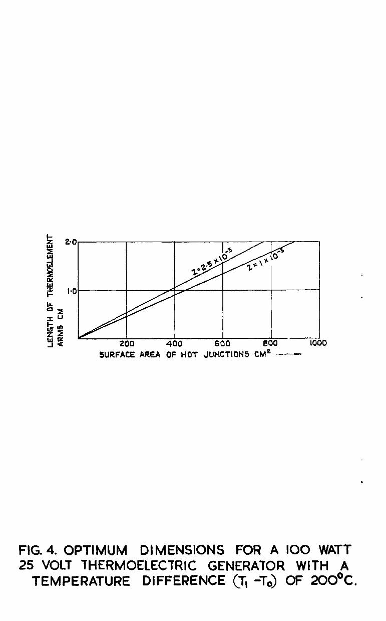
Optimum dimensions for a 100 watt thermoelectric generator with a temperature difference (T,-To) of 2OOOC
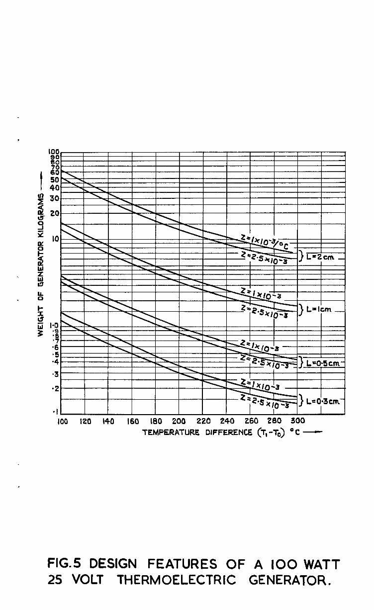
Design features of a 100 watt thermoelectric generator
4
5
-2-
1 INTRODUCTION
IT two dissimilar materials are connected to each other at two points to form an eleotrio circuit, and the two junctions are maintained at differ- ent temperatures then, depending on the thermoeleotrio properties of the two materials, a current will flow in the electric circuit. If a resistive load is now inoluded in the circuit, electrical energy will be dissipated in the load. A thermoelectric generator of this type may have application in systems where waste heat may be utilised by direct conversion into electrical energy an& used to supply or control devices within the system. Since the thermo- eleotrio effects are reversible they might also be applied to looal refrigera- tion or temperature oontrol systems.
It is the purpose of this note to examine the possibilities offered by thermoelectric devices and to discuss the present position and future prospects in the field.
2 THE XATURE OF THE THERMOELECTRIC EFFECT
When a circuit is formed by two dissimilar =terial.s and the junotions are maintained at different temperatures by some external agency, two types of thermoelectric effect may be apparent:-
(1) The Seebeok effect
This gives rise to an eleotromotive force in the circuit by virtue of the temperature difference between the two junctions. The reverse effect, known as the Peltier effect, causes heat to be emitted at one junction and absorbed at the other when an electric current is passed through the circuit.
(2) The Thomson effeot
This gives rise to an e.m.f. in any element of temperature gradient. This effect is usually small effect over the range of temperature difference3 for most usefully be employed.
material which supports a compared with the Seebeck which thermo-couples may
The ratio of change of the total e.m.f. in the circuit with change in temperature difference between the junctions is known as the Thermoelectrio Power a of the oircuit. --
The Efficiency q of a thermoeleotric generator is the percentage of the rate of consumption of thermal energy which is delivered to the load as elec- trical power. Thus for a generator of high efficiency, materials are required which have a high value of thermoelectric power a and whioh have low values of thermal conductivity k, so that for a fixed temperature difference between the hot and cold junctions a minimum of heat will be lost irreversibly by conduction down the branches. For a given load the maximum efficiency is achieved with a generator having minimum internal impedance; this demands thermoeleotrio materials of low speoific resistivity p.
2 It can be shown that the parameter 2 = L is a convenient figure of
kP merit with which to describe thermoelectric materials? (Refs.1 and 2.)
* Some British workers use the square root of this value, viz. e*
-3-

The most suitable metals with a hr 40 pV"C have a value of 2 around 0.3x10m3fi which leads to efficiencies of only 4% for generators using these materials. Thermoeleotrio generators really only become a practical proposition when effioienoies approaching 1% can be achieved and, with existing semi-conductor materids which have values of Z greater than I x 10-3, this should be possible.
3 THE CHOICE OF THERMOELECTRIC MATERIALS
The properties which affect the figure of merit are all functions of the carrier concentration n, that is, electrons or, in the case of some semi-
oonductors, "positive holes". The electrical conduotivity Q = $ is roughly
proportional to n whilst the thermoelectric power a tends to zero when n tends to infinity, and a tends to infinity when n goes to zero. But when n is reduoed to zero p is very large and hence the figure of merit might not
2 be increased. Electron theory indicates that %- will be a maximum when
n N 10” omB3 P
, which is 1000 times smaller than for metals and is in the realm of aemioonduotors. is around 200 @/OC.
It can be shown also that the optimum value for a The thermal oonduotivity k of a substance is the sum
of two parts: that due to the free carriers kel and proportional to n, and that due to lattice vibrations k
the concentration n = 10 19 .,-3,PE (phonons) which is independent of n. At
el is small. For a large figure of merit
Z to be obtsined, a high value of the ratio %is required ooupled with a
large value of ct. The minimum value of k is given by k ph'
which is obtained when n is zero, but we must accept a small n since d must be as large as possible. Now cr =nue, the carrier charge,
where u is the carrier mobility and e is so we need carriers of high mobility. High values of u
are found in inter-metallic compounds of medium atomic weight, e.g. indium antimonide, and low values of k
ph are found in compounds and alloys of the
heavy elements particularly in the middle groups of the periodic system.
Since a2 varies more rapidly with n than do d and k it is possible to "dope" the material with carriers (assuming there were to; few carriers present initially) to give a favourable value of a. This treatment may also
increase the ratio E, which msy be further improved by a reduction of the
lattice thermal conductivity k Ph
by the addition of an impurity compound which
crystallises into the lattice in such a way that phonons are scattered, but eleotrons, with their longer wavelengths, are not affected, and their mobility is unaltered:<.
The materials used for thermoelectric generation are intermetallics of Pb, Hg, Bi, T& and possibly Sb, with Re, Se and S. The most advantageous arrangement is for one branch of each thermocouple to be an n-type semi- conduotor (having an excess of carrier electrons) and the other to be a p-type semiconductor (having a deficit of carrier eleotrona, that is, an excess of positive holes). Bismuth Telluride has been gradually developed (Refs.3-7) until an alloy Bi2 Te - Sb2 Te3 has now been produced which
gives an overall figure of merit3for a p-n junction of 2.4 x 10⁻³/oC. If this could be incorporated into a generator with the junctions operated at 600'~ and 300°E the optimum efficiency of the device would be 11.4%.
f
* Up till 1954 materials of high thermoeleotrio power had been selected and an impurity added to decrease the resiativity and also the brittleness (Ref.8).
-t-

Given a material of high figure of merit, it might be possible to reduce the thermal conductivity without affecting the eleotriaal conduotivity by obtaining the material in powdered or laminated form.
4 THE APPLICATION TO A THERMOELECTRIC GENERATOR
The efficiency of a thermoelectric generator ?l is given by r) = F , a
where W is the useful electrical power delivered to the load, and Qa is the net amount of heat absorbed by the hot junotion per unit time.
Considerin a single thermocouple connected to a load R, we have that, following Joffe f Ref.q):-
L= W v = Q
a Ql + Qh -$I*r
where Q, is the rate at which Peltier heat is absorbed at the hot junction at
temperature T, due to the current I passing through the circuit. This is
equal to aIT,. Qh is the rate at which heat is conducted down the branches
from the ho% junction to the cold junction at temperature To.
Thus T, - T
'h = (k, S, + k2 S2) 4 L/= K (T, - To) (21
where k,, k2 and S,, S2 are the thermal conductivities and cross-seotional
areas of the two branches respectively, and L is their length. K is there-
fore a lumped constant. I 2 The term T I r in equation (1) represents half the
Joule heat which is dissipated within the thermocouple of impedance r and which, as an approximation, may be taken to appear at the hot ¬ion.
Now
where R is the load impedance and putting m = $, we obtain
Q, = a2 T, (T, - To)
r(m+-l
and
w = a* (T,-To)* m
r(m+1)2
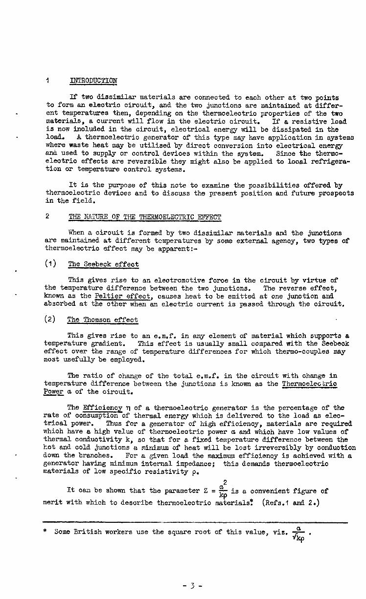
Substituting these values in equation (1) we get
m
-f-l = T1 - To G=7 T1 ',+a?
- . m-k1
7 Tl - To l -y”Zpzq
(3)
For an arbitrary value of m the maximum efficiency is given when Kr is a minimum and this occurs when
PI k2 s2 1
p2 = SP (3
whence
For a given value of internal resitance r, occurs when R = r;
the maximum delivery of power but the maximum efficiency occurs for R > r, in fact,
for a value of m given by opt = M = ,1-o). (4)
In practice PrI will vary between 1 and 2. The gain in efficiency - obtained by optimising the ratio t rather than taking R = r may be up to I$
of the total energy dissipated. Yhen R = r the efficiency is given by
T, ” Tn 2T, z . rl = ' T, " ' 8 + z (3T,-ToI l
(5)
Substituting the value of z obtained from equation (4) into equation (3) we get
The first factor in equation (6) corresponds to the thermodynamic efficiency of a reversible engine, and the second represents the reduction of this efficiency due to losses by thermal conduction and Joule heat. It should be noted that both factors are increased by raising the temperature Tl.
In order to aohieve the maximum possible efficiency then, only one condition has to be satisfied, namely, that the materials chosen should have the highest possible value of z oompatible with the temperature T, of the heat

source ; (T., + To)
that is, 2; 2 should be a maximum. Fig.1 taken from Ref.1 shows a plot og optimum efficiency q against T, for various values of 2 assuming TO
~300 K.
Referring to equation (I), it is usually found for small ourrents that Qh is the dominant term in the denominator, thus
r) w WL ?2 'h = N (k, S, + k2 S2)(T, - To)
where N is the number of thermooouples oomprising the generator. It should be noted that the electrical power W which is dissipated in the load is also proportionalto N, so that the effioienoy of the generator is independent of the number of thermocouples of which it is oomposed. Suppose =kand p, = ~2, theniS, = S2 = S and we have the power output from
= k, thermooouple
equal to
E 2 k S rl (T, - To> N = L .
Thus the electrical pcwer generated by each thermocouple depends not upon S and L separately, but only upon their ratio. For a given power required this means that the length of the thermoelements is determined by the area avail- able for heating the hot junotions. volume increases as L-2,
Also, the power obtainable per unit and is limited only by the restriotions that the
eleotrioal resistance of the junotions must be small oompared with the resistanoe of the arms of the thermoelements, and that the temperature drops between the heat souroe and the hot junotions of the thermoelements and the heat sink and cold junctions must be small oompared with the temperature drop between hot and oold junctions of the thermoelements. There may also be mechanical limitations on the length L imposed by the brittleness of the semi- conductor material, and the allowable distortion of the generator due to thermal expansion, since the shorter the arms of the thermoelements, for a given temperature differenoe between hot and cold junctions, the greater the curvature of the slab of elements forming the generator.
5 THE CHARACTERISTICS OF SOME EXISTIMG THKRMOELECTRIC DEVICES
The construational details of thermoelectric generators are only avail- able for some of the early devices which were very inefficient in regard to power output per unit volume. A Russian generator designed to operate a radio receiver from a standard oil lamp gave an output of 1.62 watts at the rate of only O.Ol watt/co of thermoelectric material, but this was by no means an optimised design. 3000 thermocouples were used in the device, the cross- sectional area of those in the heater oirouit being 6.4 x 5.1 mm to carry 0.5 amp at 1.2 volts and those in the anode circuit being I .6 x 1.6 mm to supply O.Ofl amp at 90 volts. The thermoelements were of constantan in the form of braided wire, and zinc antimonide, in proportions 35 Zu : 65 Sb with 7% of Fb to deorease resistivity and inorease the strength. The thermo- element blooks were sintered into the form shown in Fig.2 with the separate elements insulated with asbestos lagging. The thermocoupl8 arms were 2.20 om long and during operation the temperature differenoe maintained across them was 2OOOC. Another type of generator of similar size and oonstruotion was oapable of giving an output of 5 watts. In addition, a generator giving 15-20 watts, again from a kerosene burner, has been produoed to feed radio transmitters. The Russians are also manufacturing generators of 200 and 500 watt capatxity, and a 100 watt experimental solar thermoelectric generator is already in operation (Ref.1).
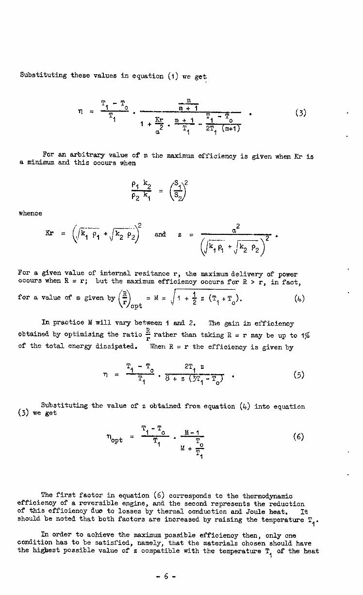
An early American device built as a solar thermoeleotrio generator gave an output of 0.165 watts for a temperature difrerenoe of 46’C (Ref.9). The thermoelements were 2.5 cm in length and oomprised bars of zino anti- moni& and an alloy of 91 bismuth 9 antimony. Here the power output per unit volume was only 0.0017 watt/co, the limiting faotor on the siae of the thermoelements being the meohanioal strength of the alloys.
Reoently the Americans have disolosed details (Ref.10) of a 5 watt thermoeleotrio generator weighing 2.3 kg which was suitable for powering radio transmitters in satellites and rookets. The heat was produoed by the absorption of Polonium alpha partioles whioh established a maximum tempera- ture differeme Op 400°C between the hot and cold junotions, and the effioienoy of oonversion of heat into electrical energy was s. The devioe had a smaller surface area than an equivalent solar (photovolfaio) battery.
Recent work on oommeroial thermoelectric devioes has been to produoe domestio refrigerators employing the Peltier effeot. A Russian water cooled unit (Ref.1) contained around 50 gm of semiconduotor material and oonsumed approximately 50 watts. Other applications included a thermostatio devioe for eleotronio equipment featuring automatic cooling and heating.
In the Unite; Kingdom the only reported work on resent practioal devices has been that of an experimental unit for the oooling of individual components of an electrioal cirouit. Efficiency of operation of the oir-
'ouit might be lost if all the oomponents had to be maintained at the msximumx operating temperature of the most temperature-sensitive component. Bismuth telluride n and p type elements having a figure of merit of 1.1 x 10°3/oC were used, Eaoh element was of dimensions 3 x 5 x 7 mm, and diffioulties associated with the extreme brittlensss of the material and the adhesion of the copper strips linking the junotions were overoome in this particular design applioation.
6 THE 8@RITS AND APPLICATION OF THERMOELECTRIC DEVICE%
The advantages of thermoeleotrio devices are that they oan be used to convert into useful electrical power heat energy whioh would otherwise be wasted, they oontain no moving parts, they are silent, they should require no servioing during use, and a long operational life may be expected from them. Their low effioienoy renders them unsuitable for the large soale
9 generation of elzotrio power, but for oertain applications they become a practioal proposition when one or other of their advantages is a design requirement.
A design study is given in Appendix 1 for a 100 watt thermoeleotrio generator giving an output of 4 amps at 25 volts. The form of oonstruotion was taken to be similar to that illustrated in Fig.3. The weight of swh a generator is shown in Fig.5 as a funotion of temperature diffarenoe between hot and cold junotions, the figure of merit for the thermoelement materials, and. the length of the thermoelement arms. By comparison, an existing niokel- cadmium oell, one of the most compact types for high disoharge rates, having a weight of 700 gm and a volume of 200 cc, at 20 volts for only 24 to 3 minutes.
is capable of delivering 120 watts A 24 volt 4 ampere-hour lead aoid
acoumulator would weigh 2.8 kgm.
From Figs.4 and 5 it oan be seen that a 100 watt thermoelectric gema- tor made from materials of a figure of merit of 2.5 x 10-f and with arms 0.4 om long supporting a temperature difference of 200°C, would weigh about 600 gm and would have a surface area of hot junotions of 150 sq om, Assuming a ooeffioient of ewsion of 2 x 10⁻⁵/°C for the semioondwtor materials the generator, if in the form of, say, twelve &rips I cm wide, would bow to a radius of 100 om. If each strip were freely supported at say its centre this would involve the edges of eaoh strip moving about 2.0 mm from the quiescent Plane. If this movement were restricted by clamping, the thermal stresses set
-8-

up might be sufficient to cause cracking of the thermoelements. It is possible that this might be overcome to some extent by the use of a plastio material for insulation of the elements.
It does appear then that, provided temperature differentials of the order of 2CD°C or greater are available, there is a strong possibility that thermoelectric generators, after a oomparatively short period of research and development, could compete on a weight-for-weight basis with more conventional sources. The problems to be considered in the installation of the generators will be the oonstruction and mounting difficulties, the absolute temperature level at which the temperature differential is obtained and the fad that this differential may only exist for a short time.
It should, however, be emphasised that such devices would be harnessing a source of heat which is available as a result of the degradation of mechanical, electrical or chemical energy in some primary process such as propulsion or room heating, and where a convenient heat sink is also available. It is only in these circumstances that the favourable weight-for-weight comparison is justified, since no acoount has been taken of the weight of the heat source or the means by which the heat is supplied to and rejected from the thermopile, for example, duoting or oooling fins. In oertain specialised applications as in the American nuclear fuelled generator (Ref.10) where the long life makes a thermoelectrio device attractive as a primary souroe of power, the weight com- parison discussed above is no longer valid sinoe here the weight of the heat source is an appreciable fraotion of the weight of the oomplete unit.
It should not be forgotten that thermoelectric devices oan also be used for refrigerating small components quite economically (the same criteria hold for their design as for generators) and also for controlling the temperature of, for example, eleotronio equipment, by regulating the dire&ion of ourrent flow through the thermoelectric elements.
7 CONCLUSIONS
Once engineering and production difficulties have been solved it is poss- ible, using materials whioh have now been developed, that thermoeleotrio devioes can be produced which oan give a small but useful supply of electricity at the expense of no great bulk provided that the heat source and sink are available in a convenient form. A satisfactory power to weight ratio oompared with conven- tional power supplies can be achieved if the hot and oold junctions are of the order of 1 om apart, and the sucoessful operation of the devices will depend on their being satisfaotorily mounted thermally, eleotrioally and mechanically. Efficiencies are not greater than about IO per cent at present, and this will prohibit their use for large scale produotion of electrioity, but even with efficienoies as low as 5 per oent thermoelectric devices have been used as small primary sources of eleotrio power in applications where their long life without attention has proved attractive.
LIST OF SXMBOLS
a thermoelectrio power g
rl W thermoelectric efficiency c
k thermal conductivity
d eleotrioal conduotivity
-9-

LIST OF SYMBOLS (Contd.)
P
r
B
m
M
Z
Z
n
U
e
W
I
IT
E
N
S
L
K
Q
T
speoific resistivity $
electrical resistance of a thermocouple
load resistance
R ratio ';I
optimum ratio
2 figure of merit of a thermoelement, L
4J
figure of merit of a thermoelement "pair", defined in Section 4. of the text
ccncentration of oarrier eiectrons or "holes"
oarrier mobility
electronic oharge
electrical power delivered to load
ourrent
voltage
generator open circuit voltage
nuuber of thermocouple3 comprising a generator
swfaoe asea
length
lumped constant, defined in Seation 4 of the text
rate of dissipation of heat
temperature
No. Author
1 Joffe, A.F.
2 Jaumot, F.E.
LIST OF ,REZERkNCES
Title. etc.
Semiconductor thermoelements and thermoeleotric oooling. Infosearch London, Press Ltd.)
1957. (Distributed by Cleaver-Hume
Thermoelectric effects. l'roc. I.R.E. &6, 538, 1958.
.
- 10 -

LIST OF REFERENCES (Con+&) -
$c&
3
4
5
6
7 Wright, D.A.
8 Telkes, M.
9
10
Telkes, M,
Barmat, M., SNAP III - Electricity from radionuclides and Anderson, G.M., thermoelectric conversion. Bollmeier, E.W. Nucleonics a, 166, 1959.
Author Goldsmid, H. J., Douglas, R.W.
Goldsmid, H.J.
Shilliday, T.S.
Goldsmid, H.J., Sheard, A.R., Wright, D.A.
Title, eto. The use of semi-conductors in thermoelectric refrigeration. Brit. J. App, Phys, 2, 386, 1956.
Thermoelectric applications of semiconductors. J. Electronics, 1, 218, 1955.
Performance of composite Peltier junctions of Bi2 Te3. J.App.Phys. 28, 4035, 4957.
The performance of bismuth telluride thermo- junctions. Brit. J. App. Phys. 2, 365, 1958.
Thermoelectric properties of bismuth telluride and its alloys. Nature%, 384,1958.
The efficiency of thermoelectric generators. J.App.Phys. 18, 1116, 1947.
Solar thermoelectric generators. J.App.Phys. 2, 765, 1954.
-11 -

APPENOIX 1
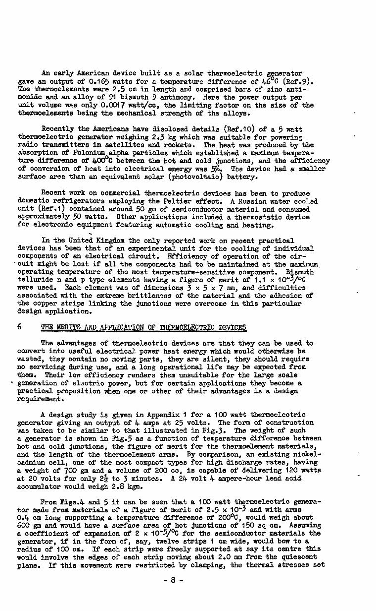
OPTIMUM DESIGN FOR A 100 l'fAT7. 25 VOLT THER%OELEXTRIC GENERATOR
It is assumed that materials which are known to exist and to have values of z of around 2.5 x 10*3/oC will be suitable and available for fabrication into compact and optimised thermoelcotric generators.
Let the 100 watts be supplied in the form of 4 amps at 25 volts, that is, given a load resistance of 6,25 ohms. Suppose a heat source is available to maintain the hot junctions of the generator at T, = 500°K and an infinite sink to maintain the cold junctions at To = 3OO'K.
The optimum ratio of the load resistance R to the internal impedance r is given by:-
?I----- .--
? +$z (T,+To) = ,+4.00 = ~.414. lo3
The maximum efficiency attainable is
T1 - To %ax = T,
x M-l TO M+ y
1
= 500 . 2oox~xloo
= 8.22%.
NOW we have that the required output from the generator
E = I (R+r)
Sinoe the voltage output from each couple is a, (T, -To) the total number of
couples required is N = a(T1'*
Assuming that the two thermoelectric materials have nearly optimum values for the thermoelectric power, namely 4-200 ~J;V/'C and -200 PVPC respectively, giving a = 4.00 pV/oC, we obtain N = 533 and r = R/h4 = 4.42 ohms.
If L is the length and S the cross-sectional area of each thermoelement,
we have that r = where p is the mean specific resistivity of the two
thermoelectric materials, which is assumed to be 1.0 x IO -3 ohm cm.
- 12 -

Therefore we obtain that i = 4.42 x lot3 = 1066
4 l5 cm-l . . Fig.4 shows the total surface area occupied by the hot junctions of the generator as a function of the length of the thermoelement arms. An allowance of 50% of the cross-seotional area of the thermoelements was made for the insulation between elements. The estimated weight of the generator is shown in Fig.5 as a function of temperature difference between hot and cold junctions, the figure of merit, and the length of the thermoelement arms. Considering a form of construction similar to that illustrated in Fig.3 the depth of the generator was assumed to be 20$ longer than the lengths of the arms to allow for the metal links and insulation.
The overall density of the generator was taken to be 7.2 &cc. Table I below gives the number of thermocouples for each type of generator and also the dimensions of each thermoelement.
TABLE I
Figure of Temperature Number of Length of 'Cross-section of each ?
merit e difference per OC
(Tl;cTO)
thermocouples thermoelement thermoelement assumed required srm square of side
N cm cm
0.3 0.32 100 1790 1.0 0.58
2.0 0.82 *
I x lo+ 0.3 0.23
200 890 I 1.0 0.41 2.0 0.58
0.3 0.18 300 590 1.0 0.34
2.0 0.48
0.3 0.38 100 1080 1.0 0.69
2.0 0.97
2.5~10-~ 0.3 0.27
200 530 1.0 0.49 2.0 0.70
0.3 0.22 300 350 1.0 0.41
2.0 0.57 t I
i
- 13 - Uf.aD78.C.P.YSS.KS - Printed in England

I’ /’ H7 I’
HOT JUNCTION I TEMPEFATURE 7 (-r,)O K
I . ICI 400 500 600 700 800 900
FIG.1 THE EFFECT OF HOT JUNCTlON TEMPERATURE AND FIGURE THE EFFICIENCY OF THERM00COUPLES.
OF MERIT ON
CONS 8RAli
HEAT SOURCE
MICA INSULATI
‘AN=l’AN ED WIRE
RED
FIG.2 CONSTRUCTION OF THERMOELECTRIC GENERATOR
HEAT SOURCE
METAL LINKS
\MICA INSULATION
FIG.3 TYPICAL CONSTRUCTION FOR THE CASE OF BOTH THERMOELEMENT
ARMS FORMED BY SINTERING.
200 400 600 800 1000
SURFACE AREA OF HOT JUNCTION5 CM2 -
FIG. 4. OPTIMUM DIMENSIONS FOR A 100 WATT 25 VOLT THERMOELECTRIC GENERATOR WITH A
TEMPERATURE DIFFERENCE CT, -To) OF 200°C.
.
I I I I I I I I I I I
I I I I I I I I I I i
I
100 126 140 160 180 200 220 240 260 280 300 TEMPERATURE DIFFERENCE (T, -TO) o C -
FIG.5 DESIGN FEATURES OF A 100 WATT 25 VOLT THERMOELECTRIC GENERATOR.


C.P. No. 499 (2 1,688)
A.R.C. Technical Report
0 Crown Copytight 1960
Published by HER MAJESTY’S STATIONERY OFFICE
To be purchased from York House, Kingsway, London w.c.2
423 Oxford Street, London w.1 13~ Castle Street, Edinburgh 2
109 St. Mary Street, Cardiff 39 King Street, Manchester 2
Tower Lane, Bristol 1 2 Edmund Street, Birmingham 3
80 Chichester Street, Belfast I or through any bookseller
Printed in England
S.O. Code No. 23-901 l-99
C.P. No. 499