AERODYNAMIC DESIGN OPTIMISATION FOR A …€¦ · ‘Aerodynamic Design Optimsation of a Helicop-...
11
1 Abstract Aerodynamic drag is an important conside- ration in helicopter design to decrease fuel con- sumption and associated emissions. The project ‘Aerodynamic Design Optimsation of a Helicop- ter Fuselage Including a Rotating Rotor Head’ – ADHeRo –, within the frame of the European Community’s Clean Sky Green Rotorcraft Con- sortium, aims to reduce parasite drag of twin engine light class utility helicopters. Performing comprehensive wind tunnel tests and numerical simulations, aerodynamic forces and moments, surface pressure distributions and wake flow fields are analyzed in detail for a specific base- line configuration. Shape modifications and means of passive flow control are applied to diminish flow separation and wake flow regions associated with high pressure drag. Conse- quently, two modified skid landing gears have been designed, namely a retrofit variant and a more progressive one. These modified skid landing gears provide an overall reduction in drag of 20.9% and 23.1%, respectively. In addition, solutions focusing on both vortex generators located at the fuselage belly ahead of the back door and port and starboard strake elements along the back door results in further drag reduction of 1.4%. Therefore, an overall drag saving of 22.3% is possible by adding retrofit parts designed within ADHeRo. The technology readiness level suggests that the corresponding configurations could be comer- cialised within a few years. Thus, ADHeRo is making an important contribution to reduce the environmental impact of light weight utility heli- copters along with lowering operational costs through reduced fuel consumption. 1 Introduction Twin-engine light (TEL) class helicopters are ideal for critical missions, including helicopter emergency medical services, search and rescue, and law enforcement activities. With a focus on novel designs that reduce emissions in air trans- port, the Green Rotorcraft Consortium (GRC) of the European Community’s Clean Sky pro- gramme is addressing environmental issues in the rotorcraft domain [1]. Regarding the heli- copter fleet of the year 2000, 10% of the global flight hours are attributed to TEL class civil helicopters. Due to the increasing number of missions it is strongly desirable to enhance the efficiency of this class of helicopters. The power requirements in fast level flight results approximately to 55 % from parasite drag, to 40% from the main rotor and to 5 % from the tail rotor [2], [3]. Aiming on parasite drag constitutes an important approach for obtaining a more effici- ent helicopter design. Parasite drag, evoked here mainly by pressure drag, is generally reduced by optimising an aircraft's shape [4], [5]. However, the shape is subject to other, often conflicting, constraints, as the design process of utility heli- copters is driven by their broad range of opera- tions and applications [6], [7]. In consequence, it is mostly not possible to choose an aerodyna- mic ‘optimal’ shape, since aerodynamic design solutions have to account for these operational constraints [8]. A typical conflict arises in the aft body region where the specifications often require a rear loading capability. Therefore, it is not feasible to minimize parasite drag in the aft body region by streamlined surfaces [9]. AERODYNAMIC DESIGN OPTIMISATION FOR A HELICOPTER CONFIGURATION INCLUDING A ROTATING ROTOR HEAD Christian Breitsamter, Moritz Grawunder, Roman Reß Institute of Aerodynamics and Fluid Mechanics, Technische Universität München [email protected] Keywords: Helicopter, Drag reduction, Bluff body wake, Flow control, Wind tunnel testing
Transcript of AERODYNAMIC DESIGN OPTIMISATION FOR A …€¦ · ‘Aerodynamic Design Optimsation of a Helicop-...
1
Abstract
Aerodynamic drag is an important conside-
ration in helicopter design to decrease fuel con-
sumption and associated emissions. The project
‘Aerodynamic Design Optimsation of a Helicop-
ter Fuselage Including a Rotating Rotor Head’
– ADHeRo –, within the frame of the European
Community’s Clean Sky Green Rotorcraft Con-
sortium, aims to reduce parasite drag of twin
engine light class utility helicopters. Performing
comprehensive wind tunnel tests and numerical
simulations, aerodynamic forces and moments,
surface pressure distributions and wake flow
fields are analyzed in detail for a specific base-
line configuration. Shape modifications and
means of passive flow control are applied to
diminish flow separation and wake flow regions
associated with high pressure drag. Conse-
quently, two modified skid landing gears have
been designed, namely a retrofit variant and a
more progressive one. These modified skid
landing gears provide an overall reduction in
drag of 20.9% and 23.1%, respectively. In
addition, solutions focusing on both vortex
generators located at the fuselage belly ahead
of the back door and port and starboard strake
elements along the back door results in further
drag reduction of 1.4%. Therefore, an overall
drag saving of 22.3% is possible by adding
retrofit parts designed within ADHeRo. The
technology readiness level suggests that the
corresponding configurations could be comer-
cialised within a few years. Thus, ADHeRo is
making an important contribution to reduce the
environmental impact of light weight utility heli-
copters along with lowering operational costs
through reduced fuel consumption.
1 Introduction
Twin-engine light (TEL) class helicopters are
ideal for critical missions, including helicopter
emergency medical services, search and rescue,
and law enforcement activities. With a focus on
novel designs that reduce emissions in air trans-
port, the Green Rotorcraft Consortium (GRC) of
the European Community’s Clean Sky pro-
gramme is addressing environmental issues in
the rotorcraft domain [1]. Regarding the heli-
copter fleet of the year 2000, 10% of the global
flight hours are attributed to TEL class civil
helicopters. Due to the increasing number of
missions it is strongly desirable to enhance the
efficiency of this class of helicopters. The
power requirements in fast level flight results
approximately to 55 % from parasite drag, to
40% from the main rotor and to 5 % from the
tail rotor [2], [3].
Aiming on parasite drag constitutes an
important approach for obtaining a more effici-
ent helicopter design. Parasite drag, evoked here
mainly by pressure drag, is generally reduced by
optimising an aircraft's shape [4], [5]. However,
the shape is subject to other, often conflicting,
constraints, as the design process of utility heli-
copters is driven by their broad range of opera-
tions and applications [6], [7]. In consequence,
it is mostly not possible to choose an aerodyna-
mic ‘optimal’ shape, since aerodynamic design
solutions have to account for these operational
constraints [8]. A typical conflict arises in the
aft body region where the specifications often
require a rear loading capability. Therefore, it is
not feasible to minimize parasite drag in the aft
body region by streamlined surfaces [9].
AERODYNAMIC DESIGN OPTIMISATION FOR A HELICOPTER CONFIGURATION INCLUDING A
ROTATING ROTOR HEAD
Christian Breitsamter, Moritz Grawunder, Roman Reß
Institute of Aerodynamics and Fluid Mechanics, Technische Universität München
Keywords: Helicopter, Drag reduction, Bluff body wake, Flow control, Wind tunnel testing
C. Breitsamter , M. Grawunder, R. Reß
2
In this context, the project ‘Aerodynamic
Design Optimisation of a Helicopter Fuselage
Including a Rotating Rotor Head’ – ADHeRo –
(http://www.adhero.de), aims on parasite drag
reduction of TEL-class utility helicopters in for-
ward flight. In parallel, the drag reduction solu-
tions should not result in an increased fuselage
down force. The main scope of the work is to
develop and evaluate several drag saving design
modifications with respect to a given baseline
TEL configuration, cf. Refs. 10 and 11.
For ADHeRo, a specific wind tunnel model
is designed, manufactured and instrumented in
order to perform detailed drag measurements.
The model provides high modularity to account
for design modifications. The model rotor head
enables the full kinematic complexity of the
original design. This includes the rotation of the
rotor head and the collective and cyclic pitch
motion of the rotor blades to provide associated
drag and lift data.
Experimental and numerical flow simula-
tions on the baseline and modified configura-
tions are addressed. The investigations on the
baseline configuration provide the reference
data for all subsequent design modifications.
These modifications focus on the skid landing
gear, the fuselage back door area, the mast
fairing and rotor head because the correspond-
ding flow separation and wake flow account for
nearly 70% - 75% of the total parasite drag [2].
Referring to the Bo105, about 38% of parasite
drag is attributed to the fuselage, 23% to the
rotor head and 13% to the landing skids. These
numbers clearly demonstrate the strong need for
drag reduction on TEL class utility helicopters
resulting in increased efficiency.
The aim of the ADHeRo project is an over-
all reduction in parasite drag of up to 20%. Con-
sequently, the power requirements for light class
utility helicopters could be reduced by some
10% resulting in a reduction in fuel consump-
tion of similar magnitude. Considering the tech-
nical readiness level of the planned modifica-
tions (TRL 6, i.e. pre-production entry level) the
prospective means could enter market in short
time after completion of the project. Thus,
ADHeRo could help reducing the environmental
impact of services provided by light class utility
helicopters in the near future.
2 Geometry and Configurations
2.1 Wind Tunnel Model Geometry
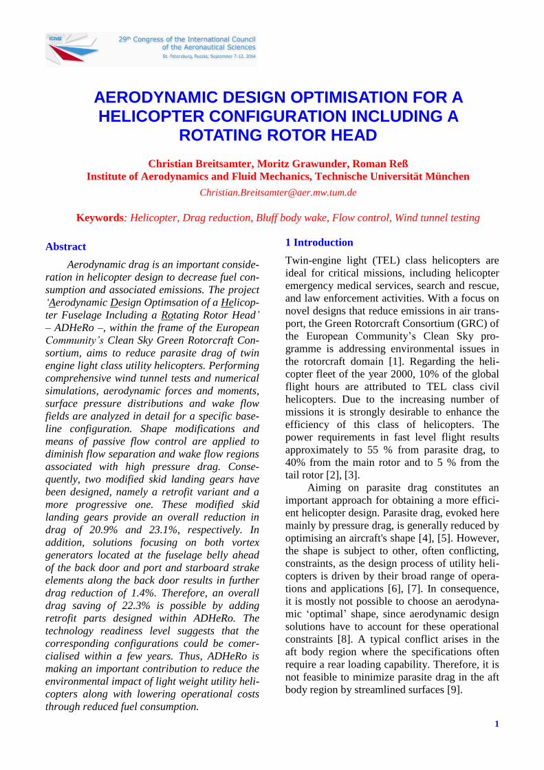
The experiments are performed on a 1:5 scale
detailed model of a characteristic state-of-the-art
TEL utility helicopter with a maximum take-off
weight of 2.95 tons (Fig. 1). Major parts of the
baseline model include front and main cabin
section, back door section, upper cowling, mast
fairing, 5-bladed rotor head, skid landing gear
and truncated tail boom. The model fuselage
parts are made of composite material and con-
nected to an inner load bearing frame made of
aluminium. A tail sting element located inside
the tail boom is used to attach the model frame
to the model support (Fig. 1).
a) Wind tunnel model
b) Model support
Fig. 1. Baseline configuration of the ADHeRo wind
tunnel model and model support.
Fig. 2. Model rotor head components.
3
AERODYNAMIC DESIGN OPTIMIZATION OF A HELICOPTER
CONFIGURATION INCLUDING A ROTATING ROTOR HEAD
The model rotor head reproduces the full
scale geometry with respect to all relevant com-
ponents exposed to the flow (Fig. 2). The rotor
head allows for collective and cyclic pitch
motion of the blade cuffs using a fully
functional swash plate. The blade cuffs are
truncated at the radial position of the first
effective aerodynamic blade section. The
attitude of the swash blade corresponds to
trimmed level flight of the full scale
configuration. A detailed description of the
design methodology of model and rotor head is
given in Ref. 10.
2.2 Configurations
2.2.1 Baseline
A variety of configurations are investigated
applying both wind tunnel tests and computa-
tional fluid dynamics to analyze the drag contri-
bution of the main fuselage and rotor head
components. The configurations associated with
the baseline or reference model, respectively,
comprise [10]:
Isolated fuselage configuration
Fuselage with skid landing gear
Fuselage with rotor head
Fuselage with skid landing gear and
rotor head
Design modifications are carried out for the skid
landing gear, the back door area and the rotor
head and mast fairing. In the present paper, the
drag savings due to the modified shape of the
landing gear and the passive flow control devi-
ces at the back door section are discussed while
rotor head and mast fairing variants are still
under investigation.
2.2.2 Landing Gear Shape Modifications
Focusing on shape optimisation, the following
modifications are tested for the skid landing
gear:
Retrofit variant (L1)
Progressive variant (L2)
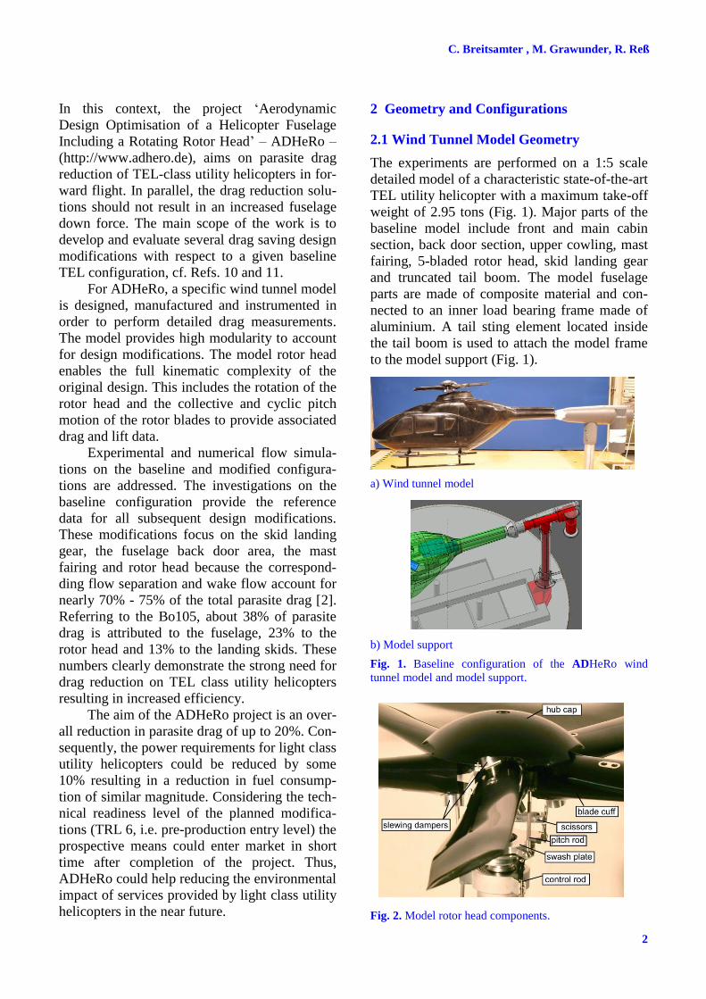
The design process for the optimized landing
gear variants is described in detail in Ref. 11.
The form and interference drag is reduced by
fairing the circular cross beams and attaching
a) Faired skid landing gear L1 (retrofit variant)
b) Faired skid landing gear L2 (progressive variant)
Fig. 3. Configurations with modified skid landings gears.
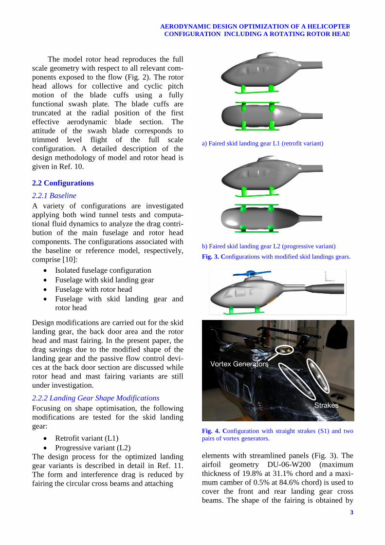
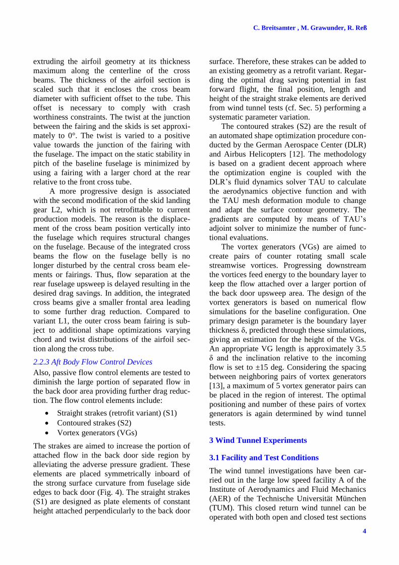
Fig. 4. Configuration with straight strakes (S1) and two
pairs of vortex generators.
elements with streamlined panels (Fig. 3). The
airfoil geometry DU-06-W200 (maximum
thickness of 19.8% at 31.1% chord and a maxi-
mum camber of 0.5% at 84.6% chord) is used to
cover the front and rear landing gear cross
beams. The shape of the fairing is obtained by
Vortex Generators
Strakes
C. Breitsamter , M. Grawunder, R. Reß
4
extruding the airfoil geometry at its thickness
maximum along the centerline of the cross
beams. The thickness of the airfoil section is
scaled such that it encloses the cross beam
diameter with sufficient offset to the tube. This
offset is necessary to comply with crash
worthiness constraints. The twist at the junction
between the fairing and the skids is set approxi-
mately to 0°. The twist is varied to a positive
value towards the junction of the fairing with
the fuselage. The impact on the static stability in
pitch of the baseline fuselage is minimized by
using a fairing with a larger chord at the rear
relative to the front cross tube.
A more progressive design is associated
with the second modification of the skid landing
gear L2, which is not retrofittable to current
production models. The reason is the displace-
ment of the cross beam position vertically into
the fuselage which requires structural changes
on the fuselage. Because of the integrated cross
beams the flow on the fuselage belly is no
longer disturbed by the central cross beam ele-
ments or fairings. Thus, flow separation at the
rear fuselage upsweep is delayed resulting in the
desired drag savings. In addition, the integrated
cross beams give a smaller frontal area leading
to some further drag reduction. Compared to
variant L1, the outer cross beam fairing is sub-
ject to additional shape optimizations varying
chord and twist distributions of the airfoil sec-
tion along the cross tube.
2.2.3 Aft Body Flow Control Devices
Also, passive flow control elements are tested to
diminish the large portion of separated flow in
the back door area providing further drag reduc-
tion. The flow control elements include:
Straight strakes (retrofit variant) (S1)
Contoured strakes (S2)
Vortex generators (VGs)
The strakes are aimed to increase the portion of
attached flow in the back door side region by
alleviating the adverse pressure gradient. These
elements are placed symmetrically inboard of
the strong surface curvature from fuselage side
edges to back door (Fig. 4). The straight strakes
(S1) are designed as plate elements of constant
height attached perpendicularly to the back door
surface. Therefore, these strakes can be added to
an existing geometry as a retrofit variant. Regar-
ding the optimal drag saving potential in fast
forward flight, the final position, length and
height of the straight strake elements are derived
from wind tunnel tests (cf. Sec. 5) performing a
systematic parameter variation.
The contoured strakes (S2) are the result of
an automated shape optimization procedure con-
ducted by the German Aerospace Center (DLR)
and Airbus Helicopters [12]. The methodology
is based on a gradient decent approach where
the optimization engine is coupled with the
DLR’s fluid dynamics solver TAU to calculate
the aerodynamics objective function and with
the TAU mesh deformation module to change
and adapt the surface contour geometry. The
gradients are computed by means of TAU’s
adjoint solver to minimize the number of func-
tional evaluations.
The vortex generators (VGs) are aimed to
create pairs of counter rotating small scale
streamwise vortices. Progressing downstream
the vortices feed energy to the boundary layer to
keep the flow attached over a larger portion of
the back door upsweep area. The design of the
vortex generators is based on numerical flow
simulations for the baseline configuration. One
primary design parameter is the boundary layer
thickness δ, predicted through these simulations,
giving an estimation for the height of the VGs.
An appropriate VG length is approximately 3.5
δ and the inclination relative to the incoming
flow is set to ±15 deg. Considering the spacing
between neighboring pairs of vortex generators
[13], a maximum of 5 vortex generator pairs can
be placed in the region of interest. The optimal
positioning and number of these pairs of vortex
generators is again determined by wind tunnel
tests.
3 Wind Tunnel Experiments
3.1 Facility and Test Conditions
The wind tunnel investigations have been car-
ried out in the large low speed facility A of the
Institute of Aerodynamics and Fluid Mechanics
(AER) of the Technische Universität München
(TUM). This closed return wind tunnel can be
operated with both open and closed test sections
5
AERODYNAMIC DESIGN OPTIMIZATION OF A HELICOPTER
CONFIGURATION INCLUDING A ROTATING ROTOR HEAD
at maximum usable velocities of 75 m/s and 65
m/s, respectively. Test section dimensions are
1.8 m in height, 2.4 m in width and 4.8 m in
length. The test section flow was carefully
inspected and calibrated documenting a turbu-
lence level less than 0.4%, an uncertainty in the
free stream direction of less than 0.2 deg, and a
variation of static pressure normalized by dyna-
mic pressure of less than 0.4% along the rele-
vant test section part. Uncertainties in the spatial
and temporal mean velocity distributions are
less than 0.067%. Because tests are also conduc-
ted for larger angles of attack and sideslip the
open test section is used.
The ADHeRo measurements have been
made at a free stream reference velocity of U∞ =
40 m/s at ambient pressure p∞ and ambient
temperature T∞. The corresponding Reynolds
number is Re ≈ 1 x 10⁶ and the free stream
Mach number is Ma∞ ≈ 0.1. Results are mainly
shown for an angle of attack of α = 0° and an
angle of sideslip of β = 0°. For some cases, an
angle-of-attack range of -10° ≤ α ≤ +10° at β =
0° is considered.
3.2 Model Integration
The model is sting mounted via the tail sting
located inside the tail boom model part. The
model tail sting is connected to a specific model
support (Fig. 1). This support provides mini-
mum model interference compared to standard
solutions using belly or head stings. The load
bearing support structure is covered so that only
the aerodynamic loads acting on the model are
measured. The model can be rolled by the
support rolling unit and yawed by the turntable
unit of the under-floor balance. Both units are
driven by gears and stepper motors. The angle
of attack and the angle of sideslip of the model
are then set by an appropriate combination of
yaw and roll angles derived from a transfer
matrix.
3.3 Measurement Techniques
Here, results are shown for aerodynamic forces
and moments and wake flow fields.
3.3.1 Aerodynamic Loads
The overall forces and moments are measured
using an external six-component under-floor
balance. The accuracy based on maximum loads
is 0.025% for the force and moment compo-
nents. These load measurements are undertaken
for the baseline and associated partial configu-
rations (i.e. with and without landing gear, rotor
head, etc.) as well as for all design modifica-
tions (here: L1, L2, S1, S2, VGs and combina-
tions). An internal six-component strain gauge
balance is used to obtain the forces and mo-
ments acting on specific configuration compo-
nents such as the landing gear and the (rotating)
rotor head. The accuracy of the internal balance
based on maximum loads ranges from 0.05% to
0.1% for the force components and from 0.8%
to 1.2% for the moment components. Thus,
interference loads can be obtained focusing here
especially on interference drag. Combining the
loads for complete and partial configurations as
well as for components a detailed drag break-
down is possible, i.e. the drag contribution of
the fuselage, skid landing gear, and rotor head
as well as the interference drag of skid landing
gear on fuselage and rotor head on fuselage can
be quantified.
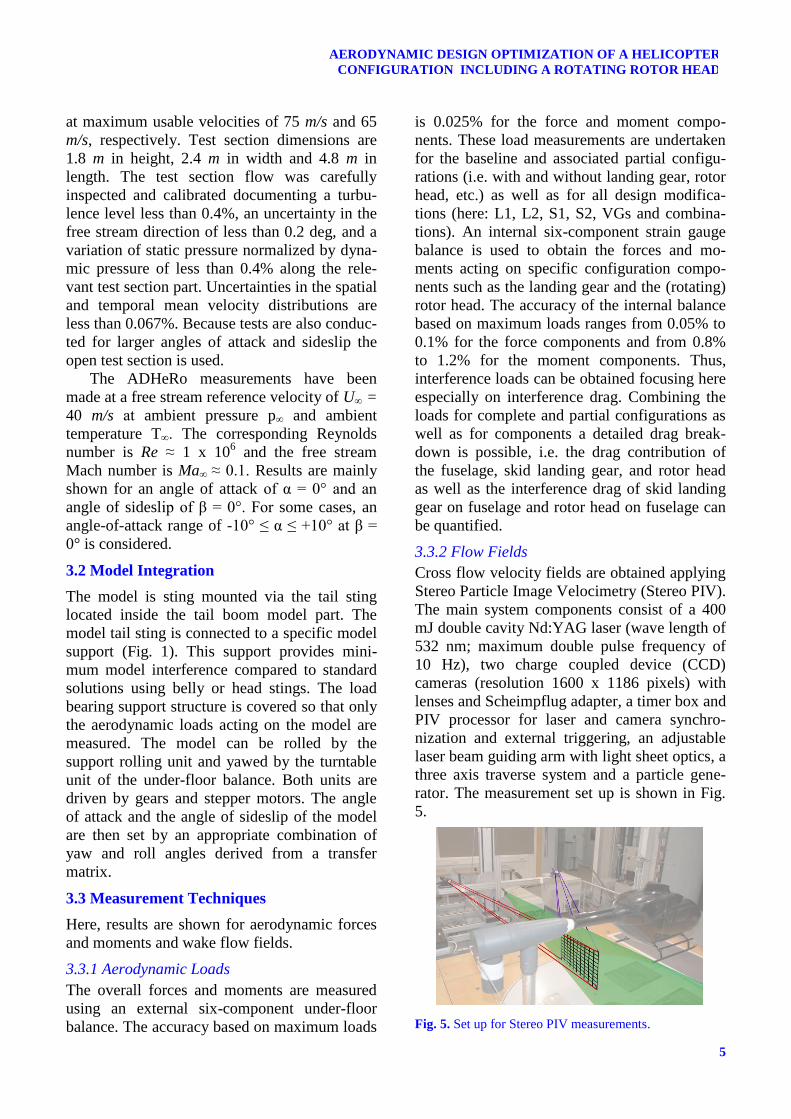
3.3.2 Flow Fields
Cross flow velocity fields are obtained applying
Stereo Particle Image Velocimetry (Stereo PIV).
The main system components consist of a 400
mJ double cavity Nd:YAG laser (wave length of
532 nm; maximum double pulse frequency of
10 Hz), two charge coupled device (CCD)
cameras (resolution 1600 x 1186 pixels) with
lenses and Scheimpflug adapter, a timer box and
PIV processor for laser and camera synchro-
nization and external triggering, an adjustable
laser beam guiding arm with light sheet optics, a
three axis traverse system and a particle gene-
rator. The measurement set up is shown in Fig.
5.
Fig. 5. Set up for Stereo PIV measurements.
C. Breitsamter , M. Grawunder, R. Reß
6
The light sheet thickness is set approximately to
5 mm and the pulse delay is set to 12 μs.
Typically, velocity fields are averaged for 100
data samples. Accuracy in the mean velocity
components is about 3% based on statistical
analysis. Considering the measured cross flow
planes, the spatial resolution based on the heli-
copter fuselage width is about 0.032 in the late-
ral and vertical direction.
4 Numerical Method
Complementary numerical simulations are
performed for selected configurations. Flow
modelling is based on the incompressible (Un-
steady) Reynolds Averaged Navier-Stokes
((U)RANS) equations employing the commer-
cial flow solver ANSYS CFX5 [14].
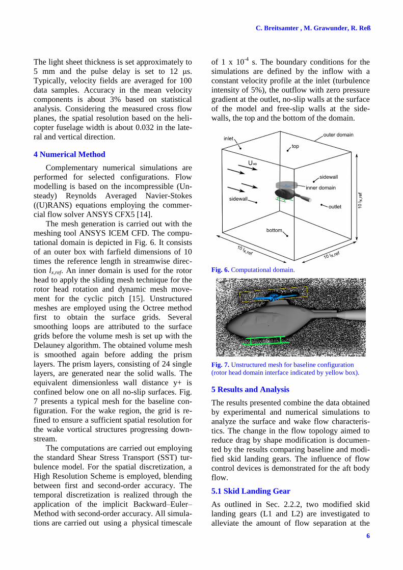
The mesh generation is carried out with the
meshing tool ANSYS ICEM CFD. The compu-
tational domain is depicted in Fig. 6. It consists
of an outer box with farfield dimensions of 10
times the reference length in streamwise direc-
tion lx,ref. An inner domain is used for the rotor
head to apply the sliding mesh technique for the
rotor head rotation and dynamic mesh move-
ment for the cyclic pitch [15]. Unstructured
meshes are employed using the Octree method
first to obtain the surface grids. Several
smoothing loops are attributed to the surface
grids before the volume mesh is set up with the
Delauney algorithm. The obtained volume mesh
is smoothed again before adding the prism
layers. The prism layers, consisting of 24 single
layers, are generated near the solid walls. The
equivalent dimensionless wall distance y+ is
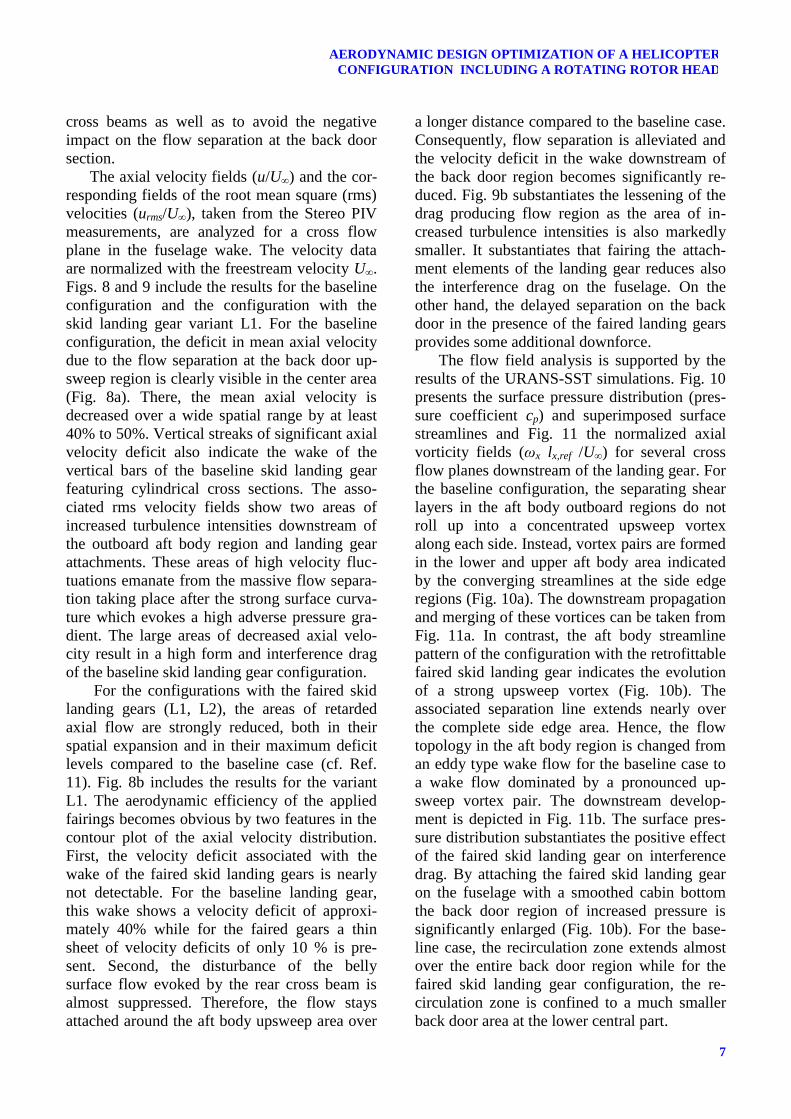
confined below one on all no-slip surfaces. Fig.
7 presents a typical mesh for the baseline con-
figuration. For the wake region, the grid is re-
fined to ensure a sufficient spatial resolution for
the wake vortical structures progressing down-
stream.
The computations are carried out employing
the standard Shear Stress Transport (SST) tur-
bulence model. For the spatial discretization, a
High Resolution Scheme is employed, blending
between first and second-order accuracy. The
temporal discretization is realized through the
application of the implicit Backward–Euler–
Method with second-order accuracy. All simula-
tions are carried out using a physical timescale
of 1 x 10⁻⁴
s. The boundary conditions for the
simulations are defined by the inflow with a
constant velocity profile at the inlet (turbulence
intensity of 5%), the outflow with zero pressure
gradient at the outlet, no-slip walls at the surface
of the model and free-slip walls at the side-
walls, the top and the bottom of the domain.
Fig. 6. Computational domain.
Fig. 7. Unstructured mesh for baseline configuration
(rotor head domain interface indicated by yellow box).
5 Results and Analysis
The results presented combine the data obtained
by experimental and numerical simulations to
analyze the surface and wake flow characteris-
tics. The change in the flow topology aimed to
reduce drag by shape modification is documen-
ted by the results comparing baseline and modi-
fied skid landing gears. The influence of flow
control devices is demonstrated for the aft body
flow.
5.1 Skid Landing Gear
As outlined in Sec. 2.2.2, two modified skid
landing gears (L1 and L2) are investigated to
alleviate the amount of flow separation at the
7
AERODYNAMIC DESIGN OPTIMIZATION OF A HELICOPTER
CONFIGURATION INCLUDING A ROTATING ROTOR HEAD
cross beams as well as to avoid the negative
impact on the flow separation at the back door
section.
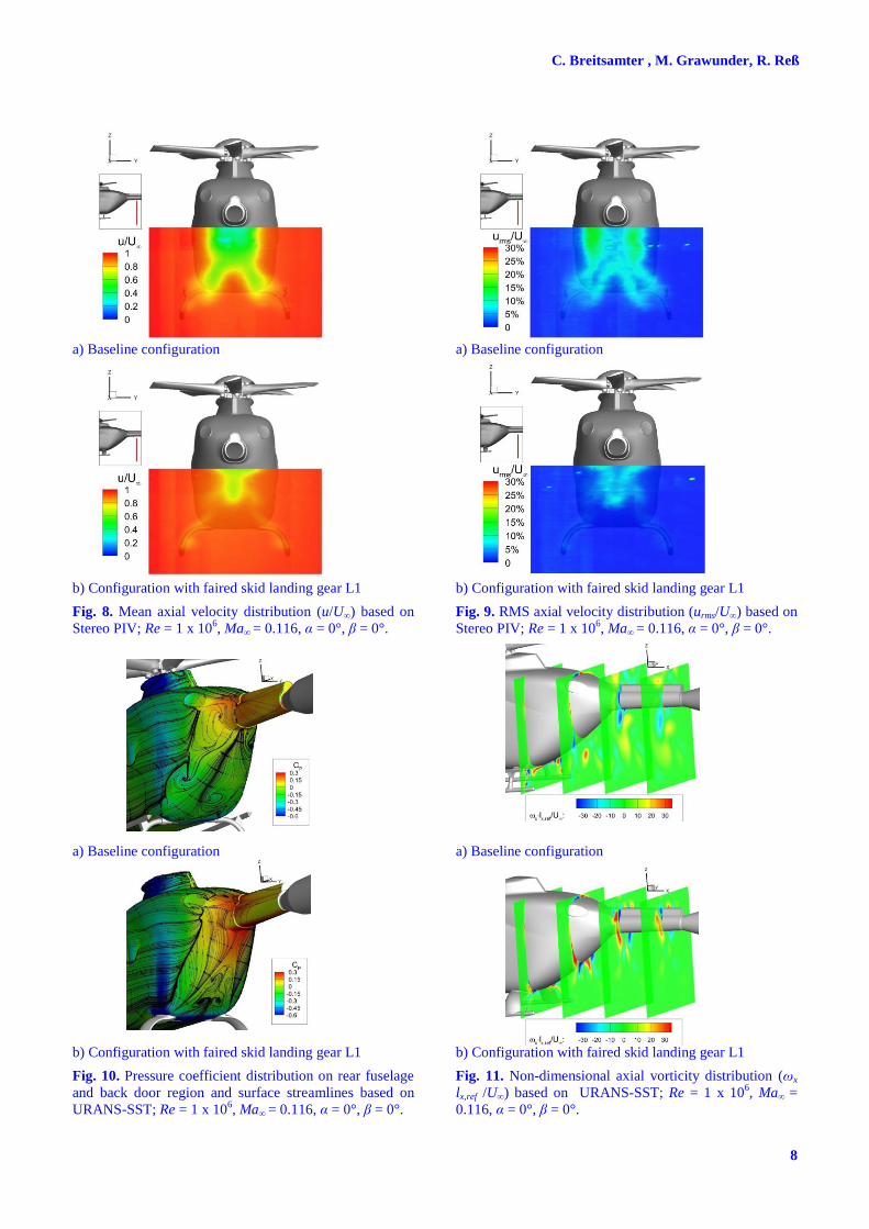
The axial velocity fields (u/U∞) and the cor-
responding fields of the root mean square (rms)
velocities (urms/U∞), taken from the Stereo PIV
measurements, are analyzed for a cross flow
plane in the fuselage wake. The velocity data
are normalized with the freestream velocity U∞.
Figs. 8 and 9 include the results for the baseline
configuration and the configuration with the
skid landing gear variant L1. For the baseline
configuration, the deficit in mean axial velocity
due to the flow separation at the back door up-
sweep region is clearly visible in the center area
(Fig. 8a). There, the mean axial velocity is
decreased over a wide spatial range by at least
40% to 50%. Vertical streaks of significant axial
velocity deficit also indicate the wake of the
vertical bars of the baseline skid landing gear
featuring cylindrical cross sections. The asso-
ciated rms velocity fields show two areas of
increased turbulence intensities downstream of
the outboard aft body region and landing gear
attachments. These areas of high velocity fluc-
tuations emanate from the massive flow separa-
tion taking place after the strong surface curva-
ture which evokes a high adverse pressure gra-
dient. The large areas of decreased axial velo-
city result in a high form and interference drag
of the baseline skid landing gear configuration.
For the configurations with the faired skid
landing gears (L1, L2), the areas of retarded
axial flow are strongly reduced, both in their
spatial expansion and in their maximum deficit
levels compared to the baseline case (cf. Ref.
11). Fig. 8b includes the results for the variant
L1. The aerodynamic efficiency of the applied
fairings becomes obvious by two features in the
contour plot of the axial velocity distribution.
First, the velocity deficit associated with the
wake of the faired skid landing gears is nearly
not detectable. For the baseline landing gear,
this wake shows a velocity deficit of approxi-
mately 40% while for the faired gears a thin
sheet of velocity deficits of only 10 % is pre-
sent. Second, the disturbance of the belly
surface flow evoked by the rear cross beam is
almost suppressed. Therefore, the flow stays
attached around the aft body upsweep area over
a longer distance compared to the baseline case.
Consequently, flow separation is alleviated and
the velocity deficit in the wake downstream of
the back door region becomes significantly re-
duced. Fig. 9b substantiates the lessening of the
drag producing flow region as the area of in-
creased turbulence intensities is also markedly
smaller. It substantiates that fairing the attach-
ment elements of the landing gear reduces also
the interference drag on the fuselage. On the
other hand, the delayed separation on the back
door in the presence of the faired landing gears
provides some additional downforce.
The flow field analysis is supported by the
results of the URANS-SST simulations. Fig. 10
presents the surface pressure distribution (pres-
sure coefficient cp) and superimposed surface
streamlines and Fig. 11 the normalized axial
vorticity fields (ωx lx,ref /U∞) for several cross
flow planes downstream of the landing gear. For
the baseline configuration, the separating shear
layers in the aft body outboard regions do not
roll up into a concentrated upsweep vortex
along each side. Instead, vortex pairs are formed
in the lower and upper aft body area indicated
by the converging streamlines at the side edge
regions (Fig. 10a). The downstream propagation
and merging of these vortices can be taken from
Fig. 11a. In contrast, the aft body streamline
pattern of the configuration with the retrofittable
faired skid landing gear indicates the evolution
of a strong upsweep vortex (Fig. 10b). The
associated separation line extends nearly over
the complete side edge area. Hence, the flow
topology in the aft body region is changed from
an eddy type wake flow for the baseline case to
a wake flow dominated by a pronounced up-
sweep vortex pair. The downstream develop-
ment is depicted in Fig. 11b. The surface pres-
sure distribution substantiates the positive effect
of the faired skid landing gear on interference
drag. By attaching the faired skid landing gear
on the fuselage with a smoothed cabin bottom
the back door region of increased pressure is
significantly enlarged (Fig. 10b). For the base-
line case, the recirculation zone extends almost
over the entire back door region while for the
faired skid landing gear configuration, the re-
circulation zone is confined to a much smaller
back door area at the lower central part.
C. Breitsamter , M. Grawunder, R. Reß
8
a) Baseline configuration
b) Configuration with faired skid landing gear L1
Fig. 8. Mean axial velocity distribution (u/U∞) based on
Stereo PIV; Re = 1 x 10⁶, Ma∞ = 0.116, α = 0°, β = 0°.
a) Baseline configuration
b) Configuration with faired skid landing gear L1
Fig. 10. Pressure coefficient distribution on rear fuselage
and back door region and surface streamlines based on
URANS-SST; Re = 1 x 10⁶, Ma∞ = 0.116, α = 0°, β = 0°.
a) Baseline configuration
b) Configuration with faired skid landing gear L1
Fig. 9. RMS axial velocity distribution (urms/U∞) based on
Stereo PIV; Re = 1 x 10⁶, Ma∞ = 0.116, α = 0°, β = 0°.
a) Baseline configuration
b) Configuration with faired skid landing gear L1
Fig. 11. Non-dimensional axial vorticity distribution (ωx
lx,ref /U∞) based on URANS-SST; Re = 1 x 10⁶, Ma∞ =
0.116, α = 0°, β = 0°.
9
AERODYNAMIC DESIGN OPTIMIZATION OF A HELICOPTER
CONFIGURATION INCLUDING A ROTATING ROTOR HEAD
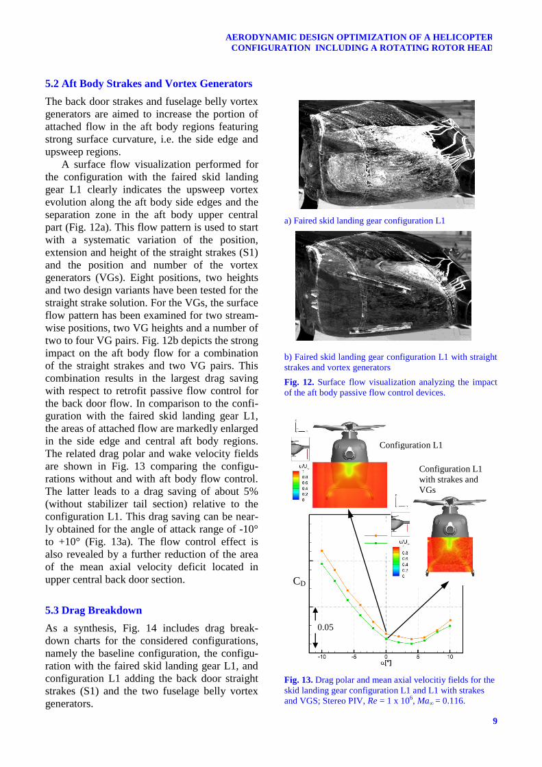
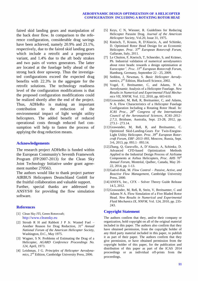
5.2 Aft Body Strakes and Vortex Generators
The back door strakes and fuselage belly vortex
generators are aimed to increase the portion of
attached flow in the aft body regions featuring
strong surface curvature, i.e. the side edge and
upsweep regions.
A surface flow visualization performed for
the configuration with the faired skid landing
gear L1 clearly indicates the upsweep vortex
evolution along the aft body side edges and the
separation zone in the aft body upper central
part (Fig. 12a). This flow pattern is used to start
with a systematic variation of the position,
extension and height of the straight strakes (S1)
and the position and number of the vortex
generators (VGs). Eight positions, two heights
and two design variants have been tested for the
straight strake solution. For the VGs, the surface
flow pattern has been examined for two stream-
wise positions, two VG heights and a number of
two to four VG pairs. Fig. 12b depicts the strong
impact on the aft body flow for a combination
of the straight strakes and two VG pairs. This
combination results in the largest drag saving
with respect to retrofit passive flow control for
the back door flow. In comparison to the confi-
guration with the faired skid landing gear L1,
the areas of attached flow are markedly enlarged
in the side edge and central aft body regions.
The related drag polar and wake velocity fields
are shown in Fig. 13 comparing the configu-
rations without and with aft body flow control.
The latter leads to a drag saving of about 5%
(without stabilizer tail section) relative to the
configuration L1. This drag saving can be near-
ly obtained for the angle of attack range of -10°
to +10° (Fig. 13a). The flow control effect is
also revealed by a further reduction of the area
of the mean axial velocity deficit located in
upper central back door section.
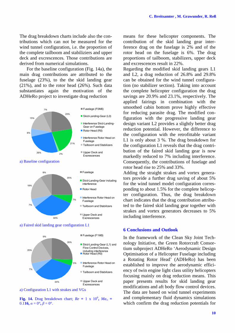
5.3 Drag Breakdown
As a synthesis, Fig. 14 includes drag break-
down charts for the considered configurations,
namely the baseline configuration, the configu-
ration with the faired skid landing gear L1, and
configuration L1 adding the back door straight
strakes (S1) and the two fuselage belly vortex
generators.
a) Faired skid landing gear configuration L1
b) Faired skid landing gear configuration L1 with straight
strakes and vortex generators
Fig. 12. Surface flow visualization analyzing the impact
of the aft body passive flow control devices.
Fig. 13. Drag polar and mean axial velocitiy fields for the
skid landing gear configuration L1 and L1 with strakes
and VGS; Stereo PIV, Re = 1 x 10⁶, Ma∞ = 0.116.
Configuration L1
Configuration L1
with strakes and
VGs
0.05
CD
C. Breitsamter , M. Grawunder, R. Reß
10
The drag breakdown charts include also the con-
tributions which can not be measured for the
wind tunnel configuration, i.e. the proportion of
the complete tailboom and stabiliziers and upper
deck and excrescences. Those contributions are
derived from numerical simulations.
For the baseline configuration (Fig. 14a), the
main drag contributions are attributed to the
fuselage (23%), to the the skid landing gear
(21%), and to the rotor head (26%). Such data
substantiates again the motivation of the
ADHeRo project to investigate drag reduction
a) Baseline configuration
a) Faired skid landing gear configuration L1
a) Configuration L1 with strakes and VGs
Fig. 14. Drag breakdown chart; Re = 1 x 10⁶, Ma∞ =
0.116, α = 0°, β = 0°.
means for these helicopter components. The
contribution of the skid landing gear inter-
ference drag on the fuselage is 2% and of the
rotor head on the fuselage is 6%. The drag
proportions of tailboom, stabilizers, upper deck
and excrescences result in 22%.
Regarding the modified skid landing gears L1
and L2, a drag reduction of 26.8% and 29.8%
can be obtained for the wind tunnel configura-
tion (no stabilizer section). Taking into account
the complete helicopter configuration the drag
savings are 20.9% and 23.1%, respectively. The
applied fairings in combination with the
smoothed cabin bottom prove highly effective
for reducing parasite drag. The modified con-
figuration with the progressive landing gear
design variant L2 provides a slightly better drag
reduction potential. However, the difference to
the configuration with the retrofittable variant
L1 is only about 3 %. The drag breakdown for
the configuration L1 reveals that the drag contri-
bution of the faired skid landing gear is now
markedly reduced to 7% including interference.
Consequently, the contributions of fuselage and
rotor head rise to 25% and 33%.
Adding the straight strakes and vortex genera-
tors provide a further drag saving of about 5%
for the wind tunnel model configuration corres-
ponding to about 1.5% for the complete helicop-
ter configuration. Thus, the drag breakdown
chart indicates that the drag contribution attribu-
ted to the faired skid landing gear together with
strakes and vortex generators decreases to 5%
including interference.
6 Conclusions and Outlook
In the framework of the Clean Sky Joint Tech-
nology Initiative, the Green Rotorcraft Consor-
tium subproject ADHeRo ‘Aerodynamic Design
Optimisation of a Helicopter Fuselage including
a Rotating Rotor Head’ (ADHeRo) has been
established to improve the aerodynamic effici-
ency of twin engine light class utility helicopters
focusing mainly on drag reduction means. This
paper presents results for skid landing gear
modifications and aft body flow control devices.
The data are based on wind tunnel experiments
and complementary fluid dynamics simulations
which confirm the drag reduction potentials for
23%
21%
2%26%
6%
15%
7% Fuselage (F0M0)
Skid-Landing-Gear (L0)
Interference Skid-Landing-Gear on Fuselage
Rotor Head (R0)
Interference Rotor Head onFuselage
Tailboom and Stabilizers
Upper Deck andExcrescences
25%
7%
33%
7%
19%
9% Fuselage
Skid-Landing-Gear includinginterference
Rotor Head
Interference Rotor Head onFuselage
Tailboom and Stabilizers
Upper Deck andExcrescences
26%
5%
34%
7%
20%
9% Fuselage (F1M0)
Skid-Landing-Gear (L1) andFlow Control Devices,including interferenceRotor Head (R0)
Interference Rotor Head onFuselage
Tailboom and Stabilizers
Upper Deck andExcrescences
11
AERODYNAMIC DESIGN OPTIMIZATION OF A HELICOPTER
CONFIGURATION INCLUDING A ROTATING ROTOR HEAD
faired skid landing gears and manipulation of
the back door flow. In comparison to the refe-
rence configuration, considerable drag savings
have been achieved, namely 20.9% and 23.1%,
respectively, due to the faired skid landing gears
which include a retrofit and a progressive
variant, and 1.4% due to the aft body strakes
and two pairs of vortex generators. The latter
are located at the fuselage belly ahead of the
strong back door upsweep. Thus the investiga-
ted configurations exceed the expected drag
benefits with 22.3% in the aggregate for the
retrofit solutions. The technology readiness
level of the configuration modifications is that
the proposed configuration modifications could
be realized shortly after the end of the project.
Thus, ADHeRo is making an important
contribution to the reduction of the
environmental impact of light weight utility
helicopters. The added benefit of reduced
operational costs through reduced fuel con-
sumption will help to fasten the process of
applying the drag reduction means.
Acknowledgements
The research project ADHeRo is funded within
the European Community's Seventh Framework
Program (FP/2007-2013) for the Clean Sky
Joint Technology Initiative under grant agree-
ment number 270563.
The authors would like to thank project partner
AIRBUS Helicopters Deutschland GmbH for
the fruitful collaboration and valuable support.
Further, special thanks are addressed to
ANSYS® for providing the flow simulation
software.
References
[1] Clean Sky JTI, Green Rotorcraft;
http://www.cleansky.eu
[2] Stroub R H and Rabbott J P Jr. Wasted Fuel –
Another Reason for Drag Reduction, 31st Annual
National Forum of the American Helicopter Society,
Washington, D.C., May 1975.
[3] Wagner, S N. Problems of Estimating the Drag of a
Helicopter, AGARD Conference Proceedings No.
124, April, 1973.
[4] Leishman, J G. Principles of Helicopter Aerodyna-
mics, 2nd
Edition, Cambridge University Press, 2006.
[5] Keys, C N, Wiesner, R. Guidelines for Reducing
Helicopter Parasite Drag. Journal of the American
Helicopter Society, Vol.20, Issue 31, 1975.
[6] Kneisch, T, Krauss, R, D'Alascio, A, and Schimke,
D. Optimised Rotor Head Design for an Economic
Helicopter. Proc. 37th
European Rotorcraft Forum,
Gallarate, Italy, 2011.
[7] Le Chuiton, F, Kneisch, T, Schneider, S, and Krämer,
Ph. Industrial validation of numerical aerodynamics
about rotor heads: towards a design optimisation at
Eurocopter”, Proc. 35th
European Rotorcraft Forum,
Hamburg, Germany, September 22 - 25, 2009.
[8] Seddon, J, Newman, S. Basic Helicopter Aerody-
namics, 2nd
Edition, Blackwell Science, 2002.
[9] Vogel, F, Breitsamter, C, and Adams, N A.
Aerodynamic Analysis of a Helicopter Fuselage. New
Results in Numerical and Experimental Fluid Mecha-
nics VII, NNFM, Vol. 112, 2010, pp. 603-610.
[10] Grawunder, M, Reß, R, Breitsamter, C, and Adams,
N A. Flow Characteristics of a Helicopter Fuselage
Configuration Including a Rotating Rotor Head. In:
ICAS Proc., 28th
Congress of the International
Council of the Aeronautical Sciences, ICAS–2012–
2.7.3, Brisbane, Australia, Sept. 23-28, 2012, pp.
273.1– 273.14.
[11] Grawunder, M, Reß, R, and Breitsamter, C.
Optimized Skid-Landing-Gears For Twin-Enegine-
Light Utility Helicopter. Proc. 39th
European Rotor-
craft Forum, ERF–2013–093, Moscow, Russia, Sept.
3-6, 2013, pp. 093.1– 093.14.
[12] Zhang, Q, Garavello, A, D’Alascio, A, Schimke, D.
Advanced CFD-based Optimization Methods
Applied to the Industrial Design Process of Airframe
Components at Airbus Helicopters, Proc. AHS 70th
Annual Forum, Montréal, Québec, Canada, May 20–
22, 2014, pp. 1-13.
[13] Gad-el-Hak, M. Flow Control – Passive, Active, and
Reactive Flow Management, Cambridge University
Press, 2000.
[14] ANSYS, Inc., CFX – Solver Theory Guide Release
14.5, 2012.
[15] Grawunder, M, Reß, R, Stein, V, Breitsamter, C and
Adams N A. Flow Simulation of a Five Bladed Rotor
Head. New Results in Numerical and Experimental
Fluid Mechanics IX, NNFM, Vol. 124, 2010, pp. 235-
243.
Copyright Statement
The authors confirm that they, and/or their company or
organization, hold copyright on all of the original material
included in this paper. The authors also confirm that they
have obtained permission, from the copyright holder of
any third party material included in this paper, to publish
it as part of their paper. The authors confirm that they
give permission, or have obtained permission from the
copyright holder of this paper, for the publication and
distribution of this paper as part of the ICAS 2014
proceedings or as individual off-prints from the
proceedings.