
Aerodynamic Control Using Windward-Surface...
7
Aerodynamic Control Using Windward-Surface Plasma Actuators on a Separation Ramp Javier Lopera ∗ and T. Terry Ng † University of Toledo, Toledo, Ohio 43606 Mehul P. Patel, ‡ Srikanth Vasudevan, § and Ed Santavicca ¶ Orbital Research Inc., Cleveland, Ohio 44103 and Thomas C. Corke ∗∗ University of Notre Dame, Notre Dame, Indiana 46556 DOI: 10.2514/1.30741 Wind-tunnel experiments were conducted on a 47-deg sweep, scaled 1303 unmanned air vehicle model to assess the performance of an innovative windward-surface plasma actuator design for flight control at low angles of attack. Control was implemented by altering the flow past an aft separation ramp on the windward side using a single dielectric barrier discharge plasma actuator. The influence of ramp-expansion angles (20, 30, and 40 deg) on the plasma actuator’s ability to affect flow separation and aerodynamic lift was examined. Both steady and unsteady actuations of the plasma actuator were examined, and their effects were captured using lift measurements and flow visualizations. Results reveal that the plasma actuator effects are highly dependent on the ramp angle and actuator parameters such as duty cycle and modulation frequency. The actuators produced significant shifts in the lift curve, up to 25% for the most effective ramp angles of 20 and 30 deg, in the 0–20-deg range. Flow visualization results confirmed that the plasma actuator causes the flow to reattach over a region downstream of the separation ramp. For all ramp cases examined, the unsteady (pulsed) actuator was more effective than the steady actuator in controlling flow separation and influencing the aerodynamic lift. The aerodynamic effect of plasma actuators was found to be highly dependent on the ramp angle and the separation strength over the ramp. Significant control forces were obtained using windward-surface plasma actuators and, indirectly, these control forces can be implemented to generate substantial control moments for maneuvering air vehicles. Nomenclature = angle of attack, deg C L = lift coefficient c = wing chord F = nondimensional frequency of actuator f mod = frequency of modulation, Hz I = current, A L sep = streamwise extent of the separation zone, m P = power, W Re c = chord Reynolds number St = Strouhal number U = freestream velocity, m=s V = voltage, V = phase angle between current and voltage in an ac circuit, rad I. Introduction T HERE has been an increased interest in recent years in expanding the functions of unmanned air vehicles (UAVs) for both civilian and military operations. Technologies that enable revolutionary capabilities in augmenting the performance of UAVs are being developed worldwide. One such technology is active flow control (AFC). AFC offers methodologies that can expand the flight envelope of UAVs, improve their aerostructural performance, and also free up the design space from the constraints of traditional aerodynamic control systems. This paper discusses an innovative active flow control approach involving a windward-surface single dielectric barrier discharge (SDBD) plasma actuator as a flow control device for providing lift and pitch control on a 1303 UAV configuration. Earlier work by Patel et al. [1] focused on lift enhancement at high angles of attack through leading-edge vortex control using plasma actuators. The present study investigates lift control at low angles of attack using a plasma actuator at the lip of a backward-facing separation ramp on the windward surface near the trailing edge. This paper presents experimental evidence of the control effectiveness of a windward-ramp plasma flow control concept at a flow Reynolds number of Re c 4:33 10 5 . The alternating current (ac) glow discharge SDBD plasma actuator offers tremendous potential as a flow control device because of its simple lightweight design with no moving parts and low power consumption. It has been shown to provide good control effects at low speeds. In recent years, there have been numerous demonstrations on the use of a SDBD plasma actuator for controlling fluid flows. Examples include exciting boundary-layer instability modes on a sharp cone at Mach 3.5 by Corke et al. [2], boundary-layer control by Roth et al. [3], lift augmentation on a wing section by Corke et al. [4], separation control on a high-angle-of- attack airfoil using plasma actuators by Post and Corke [5], separation control on stationary and oscillating airfoils by Post and Corke [6], plasma flaps and slats for hingeless flight control by Corke et al. [7], boundary-layer flow control by Jacob et al. [8], smart Presented as Paper 0636 at the 45th AIAA Aerospace Sciences Meeting and Exhibit, Reno, NV, 8–11 January 2007; received 28 February 2007; revision received 26 March 2007; accepted for publication 1 April 2007. Copyright © 2007 by authors. Published by the American Institute of Aeronautics and Astronautics, Inc., with permission. Copies of this paper may be made for personal or internal use, on condition that the copier pay the $10.00 per-copy fee to the Copyright Clearance Center, Inc., 222 Rosewood Drive, Danvers, MA 01923; include the code 0021-8669/07 $10.00 in correspondence with the CCC. ∗ Graduate Research Assistant, Department of Mechanical, Industrial and Manufacturing Engineering. Member AIAA. † Professor, Department of Mechanical, Industrial and Manufacturing Engineering. Senior Member AIAA. ‡ Director, Aerodynamics Group. Senior Member AIAA. § Aerospace Engineer. Member AIAA. ¶ Engineering Specialist. ∗∗ Clark Chair Professor, Aerospace and Mechanical Engineering Department, Associate Fellow AIAA. JOURNAL OF AIRCRAFT Vol. 44, No. 6, November–December 2007 1889
Transcript of Aerodynamic Control Using Windward-Surface...

Aerodynamic Control Using Windward-Surface PlasmaActuators on a Separation Ramp
Javier Lopera∗ and T. Terry Ng†
University of Toledo, Toledo, Ohio 43606
Mehul P. Patel,‡ Srikanth Vasudevan,§ and Ed Santavicca¶
Orbital Research Inc., Cleveland, Ohio 44103
and
Thomas C. Corke∗∗
University of Notre Dame, Notre Dame, Indiana 46556
DOI: 10.2514/1.30741
Wind-tunnel experimentswere conducted on a 47-deg sweep, scaled 1303unmanned air vehiclemodel to assess the
performance of an innovative windward-surface plasma actuator design for flight control at low angles of attack.
Control was implemented by altering the flow past an aft separation ramp on the windward side using a single
dielectric barrier discharge plasma actuator. The influence of ramp-expansion angles (20, 30, and 40 deg) on the
plasma actuator’s ability to affect flow separation and aerodynamic lift was examined. Both steady and unsteady
actuations of the plasma actuator were examined, and their effects were captured using lift measurements and flow
visualizations. Results reveal that the plasma actuator effects are highly dependent on the ramp angle and actuator
parameters such as duty cycle and modulation frequency. The actuators produced significant shifts in the lift curve,
up to 25% for the most effective ramp angles of 20 and 30 deg, in the 0–20-deg � range. Flow visualization results
confirmed that the plasma actuator causes theflow to reattach over a region downstreamof the separation ramp. For
all ramp cases examined, the unsteady (pulsed) actuator was more effective than the steady actuator in controlling
flow separation and influencing the aerodynamic lift. The aerodynamic effect of plasma actuators was found to be
highly dependent on the ramp angle and the separation strength over the ramp. Significant control forces were
obtained using windward-surface plasma actuators and, indirectly, these control forces can be implemented to
generate substantial control moments for maneuvering air vehicles.
Nomenclature
� = angle of attack, degCL = lift coefficientc = wing chordF� = nondimensional frequency of actuatorfmod = frequency of modulation, HzI = current, ALsep = streamwise extent of the separation zone, mP = power, WRec = chord Reynolds numberSt = Strouhal numberU = freestream velocity, m=sV = voltage, V� = phase angle between current and voltage in an ac
circuit, rad
I. Introduction
T HERE has been an increased interest in recent years inexpanding the functions of unmanned air vehicles (UAVs) for
both civilian and military operations. Technologies that enablerevolutionary capabilities in augmenting the performance of UAVsare being developed worldwide. One such technology is active flowcontrol (AFC). AFC offers methodologies that can expand the flightenvelope of UAVs, improve their aerostructural performance, andalso free up the design space from the constraints of traditionalaerodynamic control systems. This paper discusses an innovativeactive flow control approach involving a windward-surface singledielectric barrier discharge (SDBD) plasma actuator as a flow controldevice for providing lift and pitch control on a 1303 UAVconfiguration. Earlier work by Patel et al. [1] focused on liftenhancement at high angles of attack through leading-edge vortexcontrol using plasma actuators. The present study investigates liftcontrol at low angles of attack using a plasma actuator at the lip of abackward-facing separation ramp on the windward surface near thetrailing edge. This paper presents experimental evidence of thecontrol effectiveness of a windward-ramp plasma flow controlconcept at a flow Reynolds number of Rec � 4:33 � 105.
The alternating current (ac) glow discharge SDBD plasmaactuator offers tremendous potential as a flow control device becauseof its simple lightweight design with no moving parts and low powerconsumption. It has been shown to provide good control effects atlow speeds. In recent years, there have been numerousdemonstrations on the use of a SDBD plasma actuator forcontrolling fluid flows. Examples include exciting boundary-layerinstability modes on a sharp cone at Mach 3.5 by Corke et al. [2],boundary-layer control by Roth et al. [3], lift augmentation on awingsection by Corke et al. [4], separation control on a high-angle-of-attack airfoil using plasma actuators by Post and Corke [5],separation control on stationary and oscillating airfoils by Post andCorke [6], plasma flaps and slats for hingeless flight control byCorkeet al. [7], boundary-layer flow control by Jacob et al. [8], smart
Presented as Paper 0636 at the 45th AIAA Aerospace Sciences Meetingand Exhibit, Reno, NV, 8–11 January 2007; received 28 February 2007;revision received 26 March 2007; accepted for publication 1 April 2007.Copyright © 2007 by authors. Published by the American Institute ofAeronautics andAstronautics, Inc., with permission. Copies of this papermaybe made for personal or internal use, on condition that the copier pay the$10.00 per-copy fee to the Copyright Clearance Center, Inc., 222 RosewoodDrive, Danvers, MA 01923; include the code 0021-8669/07 $10.00 incorrespondence with the CCC.
∗Graduate Research Assistant, Department of Mechanical, Industrial andManufacturing Engineering. Member AIAA.
†Professor, Department of Mechanical, Industrial and ManufacturingEngineering. Senior Member AIAA.
‡Director, Aerodynamics Group. Senior Member AIAA.§Aerospace Engineer. Member AIAA.¶Engineering Specialist.∗∗Clark Chair Professor, Aerospace and Mechanical Engineering
Department, Associate Fellow AIAA.
JOURNAL OF AIRCRAFT
Vol. 44, No. 6, November–December 2007
1889
plasma slats for autonomous sensing and control of wing stall byPatel et al. [9], plasma optimized airfoil by Corke et al. [10], andplasmawings for hingeless flight control of a UAVby Patel et al. [1].A more detailed background on the physics and behavior of plasmaactuators are provided by Enloe et al. [11,12], and an overview ofsome of the recent developments of the SDBD actuator are presentedby Corke et al. [13].
A majority of past work on the use of a plasma actuator as a flowcontrol device has focused on flat-plate and two-dimensionalgeometries. A recent study by Patel et al. [1] has shown experimentalevidence on the use of a plasma actuator for flight control of a three-dimensional geometry: a 47-deg-sweep 1303 UAV. Although thecontrol demonstration was good at high angles of attack (between�� 15 and 25 deg), no effects were produced at low angles of attack(� < 14 deg). Results from a flow visualization study conducted onthe 1303UAVmodel suggest that at below �� 15 deg, the leading-edge vortices are intact and thus too strong to be affected by plasma.Above �� 15 deg, the vortices break down and so the leeward flowis essentially that of a stalledwing,which enables the effect of plasmato be more pronounced.
Additionally, results from flow visualization experimentsconducted in a water tunnel revealed that the windward surface(pressure side) provided a relatively simpler (two-dimensional) flowstructure that is fully attached [1]. There appears to be little, if any,crossflow component on the windward surface of the wing section.This is in strong contrast to the leeside (suction side) flow, whichexhibited a strong crossflow component. These results suggest thatthe windward-side (pressure-side) flow is potentially more receptiveto control than the suction side.
Because of the predominant complex 3-D flow structure on thesuction side, which is difficult to control, and the simpler 2-D flowstructure on the pressure side, seemingly controllable via simpleplasma actuator geometries, the current study was undertaken toinvestigate the effect of a novel windward-ramp plasma flow controlconcept for achieving lift control at low angles of attack. The purposeof the present work is to investigate the behavior of steady andunsteady plasma-induced flow over different separation-ramp angleson thewindward surface for lift control. The concept ofmanipulatingthe flow past a separation ramp to influence the aerodynamicperformance of a control surface using a flow control device is notnew; however, the application of this technique on the windwardsurface to achieve lift control has not been examined before.
The main objectives of the present work were to 1) assess theperformance of plasma actuators in conjunction with a windwardseparation ramp for providing lift control at low angles of attack and2) improve the control effectiveness by optimizing the backwardramp angle and actuator parameters such as unsteady (modulation)frequency and duty cycle.
II. Experimental Setup
A. UAV Test Model
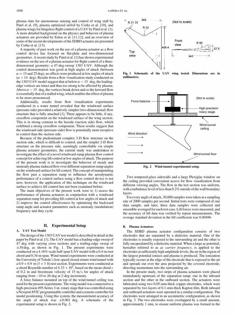
The design of the 1303UAV testmodel is described in detail in thepaper by Patel et al. [1]. TheUAVmodel has a leading-edge sweep of47 deg with varying cross sections and a trailing-edge sweep of�30 deg, as shown in Fig. 1. The present experiments wereconducted on a 4.16%-scale half-span UAVmodel with a 0.4-m rootchord and 0.34-m span.Wind-tunnel experiments were conducted atthe University of Toledo’s low-speed closed-return wind tunnel witha 0:9 � 0:9 m (3 � 3 ft) test section. Experiments were conducted ata chord Reynolds number of 4:33 � 105, based on the mean chord cof 0.2 m and freestream velocity of 15 m=s for angles of attackranging from �10 to 26 deg at 2-deg increments.
A force balance mounted on top of the wind-tunnel ceiling wasused for the present experiments. Thewingmodelwas connected to ahigh-precision 495-Series 3-in. rotary stage that was controlled usingaNewport 855Cprogrammable controller and a remote controller formodel positioning. Using this system, the measurement accuracy ofthe angle of attack was �0:001 deg. A schematic of theexperimental setup is shown in Fig. 2.
Two tempered-glass sidewalls and a large Plexiglas window onthe ceiling provided convenient access for flow visualization fromdifferent viewing angles. The flow in the test section was uniform,with a turbulence level of less than 0.2%outside of thewall boundarylayers.
For every angle of attack, 30,000 sampleswere taken at a samplingrate of 2000 samples per second. Initial tests were composed of onedata sample, and later, three data samples were collected andensemble-averaged for each test case. Lift forces weremeasured, andthe accuracy of lift data was verified by repeat measurements. Theaverage standard deviation in the lift coefficient was 0.00496.
B. Plasma Actuators
The SDBD plasma actuator configuration consists of twoelectrodes that are separated by a dielectric material. One of theelectrodes is usually exposed to the surrounding air and the other isfully encapsulated by a dielectric material. When a large ac potential,hereafter referred to as ac carrier frequency, is applied to theelectrodes at sufficiently high amplitude levels, the air in the region ofthe largest potential ionizes and plasma is produced. The ionizationtypically occurs at the edge of the electrode that is exposed to the airand spreads out over the area projected by the covered electrode,directing momentum into the surrounding air.
In the present study, two strips of plasma actuators were placedimmediately upstream of the separation ramp: one in the inboardsection and the other in the outboard section. The actuators werefabricated using two 0.05-mm-thick copper electrodes, which wereseparated by two layers of 0.1-mm-thick Kapton film. Both inboardand outboard actuators were operated in a similar configuration. Theelectrodes were arranged in an asymmetric configuration, as shownin Fig. 3. The two electrodes were overlapped by a small amount,approximately 1 mm, to ensure uniform plasma was formed in the
Fig. 1 Schematic of the UAV wing tested. Dimensions are inmillimeters.
Wind direction
Force balance
High-precisionrotary stage
(Not to scale)
Wind-tunnelceiling
Wind-tunnel floor
Fig. 2 Wind-tunnel experimental setup.
1890 LOPERA ET AL.

spanwise direction. The plasma actuator was bonded to the surfaceusing a foil tape that was attached to the base of the electrodes. Thetwo copper-foil electrodeswere aligned in the spanwise direction andmounted at the reflex line of the separation ramp.
The amount of power applied to a plasma actuator is determinedusing the formula P� �I � V� � cosine���. The phase angle on atypical transformer/actuator assembly can be as high as 70 deg. Anyphase shift between the voltage and current reduces the systemefficiency andmay also cause instability in the power amplifier.Witha phase shift of 70 deg, the system efficiency is only 34%, implyingthat 66%of the power is dissipated in the form of heat. For the currentexperiments, a phase-angle detector was custom-made to obtain theoptimum ac carrier frequency and increase the effectiveness andefficiency of the SDBD plasma actuators in producing control forceson a UAV configuration.
The actuators were tested in both unsteady and steady modes ofoperation for different duty cycles. For unsteady tests, the actuatorswere operated at F� � 1, based on the Strouhal number scalingSt� F� � �fmod � Lsep�=U� 1. This yielded a modulationfrequency fmod � 395 Hz, based on the average length of Lsep andthe selected air speed. The duty cycle is the percentage of time in aperiod that the actuator is on; thereby, a steady actuator operates at a100% duty cycle. Figure 4 shows a photograph of the plasmaactuators mounted at the onset (reflex line) of the separation ramp onthe windward surface of the wing.
C. Separation Ramp
The UAV test model was modified on the windward surface toincorporate a backward-facing separation ramp near the trailingedge. The basic premise for incorporating a ramp is to induce flowseparation past the ramp at low to moderate angles of attack. Thisregion of separated flow aft of the ramp can subsequently beinfluenced by a plasma actuator to cause a shift in the liftcharacteristics of the wing. Initial tests of the control concept usingflow visualizations with tufts for plasma on and off conditionsrevealed a strong dependency on the actuator effects on the ramp-divergence angles, which, in fact, control the “degree” of flowseparation over the ramp. Therefore, several backward ramp angles(20, 30, and 40 deg)were studiedwith plasma on and off to determinean optimal setting for maximum effect on lift. Figure 5 shows aschematic of the UAV with different ramp angle settings. Figures 6and 7 show pictures of the modified UAV design with a 20-deg
separation ramp near the trailing edge of the windward surface. Twostrips of SDBD plasma actuators were mounted at the onset of theseparation ramp: one on the inboard section and the second on theoutboard section of the wing.
III. Results
Results are presented in the form of measured lift coefficient andflow visualizations records using tufts with the plasma actuator onand off. The aerodynamic effect of the windward-surface plasmaactuators are assessed by examining the change in the lift coefficientfor baseline configurations (plasma off) and control configurations(plasma on). For flow visualization results, plasma-induced changesin the baseline flow are examined using tufts mounted on the wingsurface to determine the separated/attached state of the flow as itpasses over the ramp.
A. Force Measurements
1. Comparison of Aerodynamic Performance of Modified UAV Designs
For a practical implementation of a flow control technique on anair vehicle, in addition to producing significant control forces/moments for flight control, it is also imperative that is does notcompromise the aerodynamic performance of the vehicle in its
acvoltage
Insulated electrode
Electrode exposed to airPlasma-induced flow
Dielectric film
Aerodynamic surface(Not to scale)
Fig. 3 Schematic for windward-side aerodynamic plasma actuator;
configuration shown is composed of two electrodes arrangedasymmetrically between a Kapton (dielectric) film.
Plasma
Fig. 4 Pictures of aerodynamic plasma actuators mounted at the onsetof the separation ramp on the windward surface near the trailing edge;
(left) baseline configuration (plasma off) and (right) plasma actuator on.
A
A
B
B
C
C
The white region indicates where additional material was added to incorporate the ramp while maintaining the original chord length of the UAV at different span locations.
Section A-A
20-deg ramp
Section A-A
30-deg ramp
Section A-A
40-deg ramp
(Not to scale)
Fig. 5 Schematic of a modified UAV wing tested for different
expansion-ramp angles near the trailing edge of the windward surface.
Fig. 6 Picture of the modified wing model; (left) leeward surface and
(right) windward surface.
Fig. 7 Picture of aerodynamic plasma actuators mounted at the onsetof the 20-deg separation ramp on the windward surface; (left) outboard
region plasma actuator and (right) inboard region plasma actuator.
LOPERA ET AL. 1891

baseline (actuator off) configuration. In our study, we conductedexperiments to compare the effect of different windward-surfaceseparation-ramp angles, including a baseline (no ramp) case, toassess the aerodynamic performance of the air vehicle under differentwindward configurations. Results in Fig. 8 show that, overall, the useof a windward-surface separation ramp does not have a detrimentaleffect on the baseline lift coefficient. Results show that the separationramp leads to a slight increase in the lift coefficient at lower angles ofattack. For higher angles of attack, � > 16 deg, results show that the40-deg ramp results in a considerable increase in the lift coefficientwhen compared with the baseline design. Drag measurementsshowed small difference in the drag coefficient at low angles of attack(which is the flight envelope for the UAV design examined) for thebaseline (no ramp) case and themodifiedUAVdesignswith differentwindward-surface separation-ramp angles.
2. Effects of Ramp Angle and Duty Cycle
The first separation-ramp angle tested was a 20-deg windward-surface ramp near the trailing edge. Figure 9 shows the lift coefficientfor a baseline case (actuator off) and a controlled case (actuator on),with the plasma actuators operating in an unsteady mode at a 12.5%duty cycle. Results show that the plasma actuators produced aconsistent shift in the CL–� curve for all angles of attack from���2 to 22 deg. The effect of the windward-surface plasmaactuator is a decrease in theCL, ranging from 6 to 25% from �� 2 to20 deg.
Figure 10 shows results for a case when the plasma actuators werepulsed at a 25% duty cycle. Similar reductions in the lift coefficientwere observed for���2 to 20 deg. In this case, themost significantchanges were observed from �� 2 to 18 deg, with a decrease in thelift coefficient ranging from 5 to 30%.
Figure 11 shows results froma test conductedwith a steady plasmaactuator. Results show that a steady plasma actuator has a negligibleeffect on the lift coefficient. These results demonstrate that a pulsed(unsteady) actuator has a stronger effect on theflowfield than a steadyactuator. It has been conjectured that an unsteady actuator produces aseries of vortices convecting downstream.When the pulse frequencyproduces a sufficient number of stable vortices over the surfacecontinuously, flow reattachment occurs. This finding led us toconduct only unsteady plasma actuation experiments for thesubsequent investigations (30- and 40-deg ramps). Subsequentstudies showed that the most significant control, measured by adecrease in CL, was achieved by operating the unsteady plasmaactuators at a duty cycle of 12.5%.Additional testswere conducted toverify this effect of the unsteady plasma actuators at a 12.5% dutycycle by ensemble averaging three data sets.
Lift coefficients for the three separate tests were ensemble-averaged for the baseline and controlled cases and are presented inFig. 12. Noticeable reductions in the lift coefficient are observed for�� 0 to 20 deg. Results show that the plasma actuator decreases thelift coefficient by 4.8 to 25% for �� 4 to 20 deg. These resultsvalidate the use of a plasma actuator mounted at the onset of a
-0.1
0.0
0.1
0.2
0.3
0.4
0.5
0.6
0 4 8 12 16 20 24 28
α
CL No ramp
20-deg ramp
30-deg ramp
40-deg ramp
Fig. 8 Comparison of the effect of windward-surface backward ramp
angles on the coefficient of lift vs angle of attack for baseline (control off)
configurations.
-0.4
-0.3
-0.2
-0.1
0.0
0.1
0.2
0.3
0.4
0.5
0.6
-12 -8 -4 0 4 8 12 16 20 24 28
α
CL
Off
On: 12.5% duty cycle
Fig. 9 Coefficient of lift vs angle of attack; plasma actuators pulsedwith a 12.5% duty cycle,F� � 1, and fmod � 395 Hz; 20-deg windward-surface separation ramp.
-0.4
-0.3
-0.2
-0.1
0.0
0.1
0.2
0.3
0.4
0.5
0.6
-12 -8 -4 0 4 8 12 16 20 24 28
α
CL
Off
On: 25% duty cycle
Fig. 10 Coefficient of lift vs angle of attack; plasma actuators pulsed
with a 25% duty cycle, F� � 1, fmod � 395 Hz; 20-deg windward-surface separation ramp.
-0.4
-0.3
-0.2
-0.1
0.0
0.1
0.2
0.3
0.4
0.5
-12 -8 -4 0 4 8 12 16
α
CL
Off
On: 100% duty cycle( t d )
Fig. 11 Coefficient of lift vs angle of attack; plasma actuators pulsed
with a 100% duty cycle (steady); 20-deg windward-surface separation
ramp.
1892 LOPERA ET AL.

separation ramp near the trailing edge of the windward surface as aneffective AFC actuator capable of generating significant controlforces.
The next set of tests examined the control on a 30-deg windward-surface separation ramp. Figure 13 shows results for a 12.5% dutycycle plasma actuator mounted at the onset of a 30-deg windward-surface separation ramp. The effect of the controlled case (plasma on)is to decrease the lift coefficient. The plasma actuator decreases thelift coefficient by 2 to 15%over the� range tested, comparedwith thebaseline case. Results for a plasma actuator pulsed with a 25% dutycycle are shown in Fig. 14. The plasma actuator is more effective at a25% duty cycle on the 30-deg separation ramp. The plasma actuatorreduces the lift coefficient by 5 to 17% for the � range tested. Theseparation over a 30-deg ramp is stronger than the separationobserved over a 20-deg ramp. This stronger separation and increasedadverse pressure gradient might explain the increased effectivenessof a longer duty cycle (25%) over a shorter (12.5%) duty cycle for the30-deg separation ramp.
Results for a 40-degwindward-surface separation ramp are shownin Figs. 15 and 16. Overall, the effect of the plasma actuators isreduced at this ramp angle. Results for a 12.5% duty cycle, shown inFig. 15, show a decrease of 1 to 2% in the lift coefficient for� > 14 deg. A similar trend is observed with a 25% duty cycle,shown in Fig. 16, inwhich the plasma actuator produces a decrease of1.5 to 3% in the lift coefficient for � > 16 deg. It is expected that a
-0.1
0.0
0.1
0.2
0.3
0.4
0.5
0 4 8 12 16 20
α
CL
Off
On: 12.5% duty cycle
Fig. 12 Coefficient of lift vs angle of attack; ensemble average of three
separate tests; plasma actuators pulsed with a 12.5%duty cycle,F� � 1,
and fmod � 395 Hz; 20-deg windward-surface separation ramp.
-0.05
0.05
0.15
0.25
0.35
0.45
0.55
0 4 8 12 16 20 24
α
CL
Off
On: 12.5% duty cycle
Fig. 13 Coefficient of lift vs angle of attack; plasma actuators pulsedwith a 12.5% duty cycle, F� � 1, and fmod � 395 Hz. 30-deg windward-surface separation ramp.
-0.05
0.05
0.15
0.25
0.35
0.45
0.55
0 4 8 12 16 20 24
α
CL
Off
On: 25% duty cycle
Fig. 14 Coefficient of lift vs angle of attack; plasma actuators pulsed
with a 25% duty cycle, F� � 1, andfmod � 395 Hz; 30-deg windward-
surface separation ramp.
-0.05
0.05
0.15
0.25
0.35
0.45
0.55
0.65
0 4 8 12 16 20 24
α
CL
Off
On: 12.5% duty cycle
Fig. 15 Coefficient of lift vs angle of attack; plasma actuators pulsed
with a 12.5% duty cycle,F� � 1, and fmod � 395 Hz; 40-deg windward-surface separation ramp.
-0.05
0.05
0.15
0.25
0.35
0.45
0.55
0.65
0 4 8 12 16 20 24
α
CL
Off
On: 25% duty cycle
Fig. 16 Coefficient of lift vs angle of attack; plasma actuators pulsed
with a 25% duty cycle, F� � 1, and fmod � 395 Hz; 40-deg windward-
surface separation ramp.
LOPERA ET AL. 1893
40-deg ramp will produce a strong separation; thus, the effect of theplasma actuator might not be strong enough to overcome theaccompanying strong adverse pressure gradient.
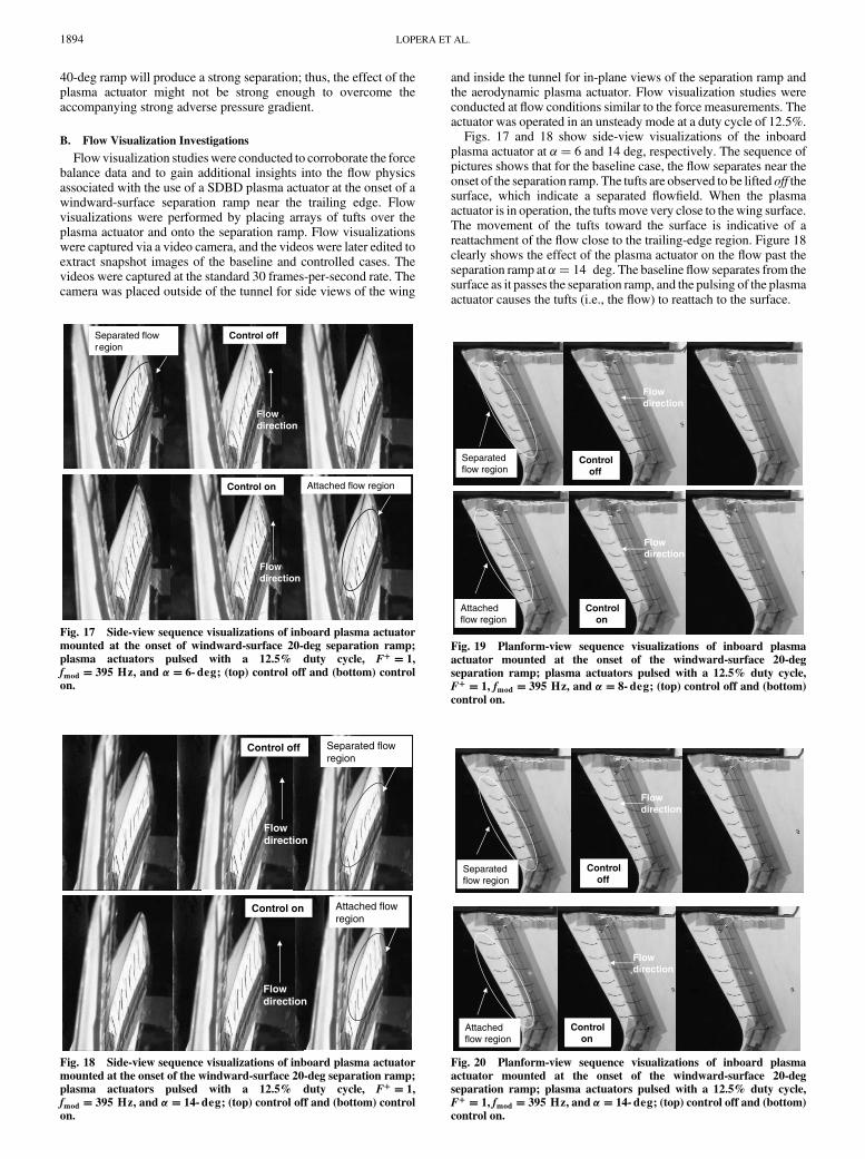
B. Flow Visualization Investigations
Flowvisualization studieswere conducted to corroborate the forcebalance data and to gain additional insights into the flow physicsassociated with the use of a SDBD plasma actuator at the onset of awindward-surface separation ramp near the trailing edge. Flowvisualizations were performed by placing arrays of tufts over theplasma actuator and onto the separation ramp. Flow visualizationswere captured via a video camera, and the videos were later edited toextract snapshot images of the baseline and controlled cases. Thevideos were captured at the standard 30 frames-per-second rate. Thecamera was placed outside of the tunnel for side views of the wing
and inside the tunnel for in-plane views of the separation ramp andthe aerodynamic plasma actuator. Flow visualization studies wereconducted at flow conditions similar to the force measurements. Theactuator was operated in an unsteady mode at a duty cycle of 12.5%.
Figs. 17 and 18 show side-view visualizations of the inboardplasma actuator at �� 6 and 14 deg, respectively. The sequence ofpictures shows that for the baseline case, the flow separates near theonset of the separation ramp. The tufts are observed to be lifted off thesurface, which indicate a separated flowfield. When the plasmaactuator is in operation, the tufts move very close to the wing surface.The movement of the tufts toward the surface is indicative of areattachment of the flow close to the trailing-edge region. Figure 18clearly shows the effect of the plasma actuator on the flow past theseparation ramp at �� 14 deg. The baseline flow separates from thesurface as it passes the separation ramp, and the pulsing of the plasmaactuator causes the tufts (i.e., the flow) to reattach to the surface.
offPlasmaoff
Plasmaon
Control off
Control on
Flowdirection
Separated flow region
Attached flow region
Flowdirection
Fig. 17 Side-view sequence visualizations of inboard plasma actuator
mounted at the onset of windward-surface 20-deg separation ramp;
plasma actuators pulsed with a 12.5% duty cycle, F� � 1,
fmod � 395 Hz, and �� 6-deg; (top) control off and (bottom) controlon.
Control off
Control on
Flowdirection
Separated flowregion
Attached flow region
Flowdirection
Fig. 18 Side-view sequence visualizations of inboard plasma actuator
mounted at the onset of the windward-surface 20-deg separation ramp;plasma actuators pulsed with a 12.5% duty cycle, F� � 1,
fmod � 395 Hz, and �� 14-deg; (top) control off and (bottom) control
on.
Control off
Control on
Flowdirection
Flowdirection
Separatedflow region
Attachedflow region
Fig. 19 Planform-view sequence visualizations of inboard plasma
actuator mounted at the onset of the windward-surface 20-degseparation ramp; plasma actuators pulsed with a 12.5% duty cycle,
F� � 1, fmod � 395 Hz, and �� 8-deg; (top) control off and (bottom)
control on.
Control off
Control on
Flowdirection
Flowdirection
Separatedflow region
Attachedflow region
Fig. 20 Planform-view sequence visualizations of inboard plasma
actuator mounted at the onset of the windward-surface 20-degseparation ramp; plasma actuators pulsed with a 12.5% duty cycle,
F� � 1, fmod � 395 Hz, and �� 14-deg; (top) control off and (bottom)
control on.
1894 LOPERA ET AL.

Planform-view visualizations near the inboard plasma actuator arepresented in Figs. 19 and 20 for �� 8 and 14 deg, respectively.These images illustrate the flow reversal and separation region thatoccur past the separation ramp. The tufts past the ramp are observedto be significantly unsteady and oscillate in a direction opposite to theflow, which is indicative of a region of flow reversal. As the plasmaactuator is pulsed, the tufts past the ramp are observed to becomemostly parallel to the flow, and there is a remarkable reduction in theunsteadiness and oscillations of the tufts. The region of “steady” tuftsclose to the surface indicates that the flow is mostly attached in theregion past the separation ramp.
By examining the flow over thewindward surface, the effect of theplasma actuator on the lift coefficient can be assessed. The plasmaactuator has the effect of reattaching the flow for some distancedownstream of the reflex line of the separation ramp. For the flow tobe reattached, the flow close to the reflex line of the separation rampneeds to accelerate around the ramp and a local low pressure isexpected to occur. This induced low-pressure region near thewindward-surface separation ramp will cause a reduction in the netpressure difference over the wing, and as a result, a decrease in lift isexpected. In addition, if the flow is reattached for most of the regionaft of the ramp, the effect of the plasma actuator would be to reducethe effective camber of the wings, thereby decreasing the overall lift.Because flow visualizations demonstrate that the plasma actuatorreattaches the flow over a region past the reflex line of the separationramp, the results correlate well with force measurements that show adecrease in the lift coefficient.
IV. Conclusions
Wind-tunnel experiments were conducted to investigate theaerodynamic effect of plasma actuators mounted at the onset of awindward-surface separation ramp near the trailing edge of a 130347-deg sweep UAV model. Results presented are proof-of-conceptinvestigations on the use of the technique for aerodynamic control ofan air vehicle. Forcemeasurements show that the plasma actuator hasthe effect of decreasing the lift coefficient comparedwith the baseline(control off) case. Results also show that an unsteady (pulsed) plasmaactuator has a significant effect on the lift coefficient, whereas asteady actuator (100% duty cycle) has a negligible effect.
Three windward-surface separation ramps with backward rampangles of 20, 30, and 40 degwere examined. Significant reductions inthe lift coefficient were obtained using the 20- and 30-deg rampconfigurations. For some conditions, reductions of 15 to 25% in thelift coefficient were obtained.With ramp angles higher than 20 deg, aduty cycle of 25% yielded the most significant decreases in the liftcoefficient, whereas a 12.5% duty cycle produces the best results fora 20-deg ramp. Further experiments need to be performed to verifythe optimal actuator parameters at higher ramp angles.
The ramp angle was found to be a critical design parameter fordetermining the effectiveness ofwindward-surface plasma actuators.As the ramp angle increases, the associated adverse pressure gradientpast the ramp increases accordingly. At large ramp angles, up to40 deg in the current study, a large adverse pressure gradient andstrong separation overwhelm the actuator effect on the flowfield andrender the plasma actuator ineffective.
Flow visualizations for the baseline case showed that the flowseparated past the separation ramp and there was a region of flowreversal. In contrast, visualizations of pulsed plasma actuatorsshowed that a region of the flow past the separation ramp wasreattached. The partial/complete reattachment of the flow past theramp is conjectured to produce a low-pressure region around theramp and thus a decrease in lift. In addition, if the flow is attached aftof the ramp up to the trailing edge, the windward-surface plasmaactuator will have the effect of reducing the effective camber of thewing and inducing a reduction in the lift coefficient.
The effect of windward-surface plasma actuators was examinedherein at 15 m=s (29 kt). A recent investigation by Patel et al. [14]investigated the scalability and effectiveness of leading-edgeseparation control on airfoils using SDBD plasma actuators. Theirexperiments demonstrated that the SDBD plasma actuator was
effective in reattaching the flow for chord Reynolds numbers up to1:0 � 106 and freestream speeds up to 60 m=s (117 kt). They alsoshowed that the optimum unsteady actuator frequency fmod
minimized the actuator voltage needed to reattach the flow, such thatF� � �fmod � Lsep�=U � 1. In addition, Patel et al. indicated that atthe optimum frequencies, the minimum voltage required to reattachthe flow was weakly dependent on the chord Reynolds number andstrongly dependent on the poststall angle of attack and leading-edgeradius.
Although moment measurements were not directly measured, itcan be indirectly inferred from the reduction of the local liftcoefficient that rolling and pitching moments could be generated byplacing the control at different parts of the air vehicle. These inducedmoments can potentially be used to control and alter the dynamics ofthe air vehicle. The flow over the windward surface of different wingplanforms is expected to resemble a 2-D flow with a weak ornegligible crossflow component. These characteristics of thewindward flowmake the windward surface a very attractive locationto successfully implement plasma actuators for aerodynamic controlof many different air vehicles.
Acknowledgments
This work was supported by Orbital Research, Inc., under a SmallBusiness Innovation Research Phase II Contract No. FA8650-04-C-3405 issued by theU.S. Air Force Research Laboratory (AFRL). Theauthors would like to thank Charles F. Suchomel, AFRL ProgramMonitor, for his insightful remarks and support of this work.
References
[1] Patel,M. P., Ng, T. T., Vasudevan, S., Corke, T. C., andHe,C., “PlasmaActuators for Hingeless Aerodynamic Control of an Unmanned AirVehicle,” AIAA Paper 2006-3495, June 2006.
[2] Corke, T. C., Cavalieri, D., andMatlis, E., “Boundary Layer Instabilityon a Sharp Cone at Mach 3.5 with Controlled Input,” AIAA Journal,Vol. 40, No. 5, 2002, pp. 1015–1018.
[3] Roth, J. R., Sherman, D. M., and Wilkinson, S. R., “Electro-hydrodynamic Flow Control with a Glow-Discharge Surface Plasma,”AIAA Journal, Vol. 38, No. 7, 2000, pp. 1166–1172.
[4] Corke, T., Jumper, E., Post, M., Orlov, D., and McLaughlin, T.,“Application of Weakly Ionized Plasmas as Wing Flow ControlDevices,” AIAA Paper 2002-0350, Jan. 2002.
[5] Post, M. L., and Corke, T. C., “Separation Control on High Angle ofAttack Airfoil Using Plasma Actuators,” AIAA Journal, Vol. 42,No. 11, 2004, pp. 2177–2184; also AIAA Paper 2003-1024, Jan. 2003.
[6] Post, M. L., and Corke, T., “Separation Control Using PlasmaActuators: Stationary & Oscillating Airfoils,”AIAA Paper 2004-0841,Jan. 2004.
[7] Corke, T. C., He, C., and Patel, M. P., “Plasma Flaps and Slats: AnApplication ofWeakly-Ionized PlasmaActuators,”AIAA Journal (to bepublished); also AIAA Paper 2004-2127, 2004.
[8] Jacob, J., Rivir, R., Campbell, C., and Estevedoreal, J., “BoundaryLayer Flow Control Using AC Discharge Plasma Actuators,” AIAAPaper 2004-2128, June 2004.
[9] Patel, M. P., Sowle, Z. H., Corke, T. C., and He, C., “AutonomousSensing and Control of Wing Stall Using a Smart Plasma Slat,” AIAAPaper 2006-1207, Jan. 2006.
[10] Corke, T. C., Mertz, B., and Patel, M. P., “Plasma Flow ControlOptimized Airfoil,” AIAA Paper 2006-1208, Jan. 2006.
[11] Enloe, L., McLaughlin, T., VanDyken, R., Kachner, Jumper, E., andCorke, T. C., “Mechanisms and Response of a Single Dielectric BarrierPlasma Actuator: Plasma Morphology,” AIAA Journal, Vol. 42, No. 3,2004, pp. 589–594.
[12] Enloe, L.,McLaughlin, T., VanDyken, R., Kachner, Jumper, E., Corke,T. C., Post, M., and Haddad., O., “Mechanisms and Response of aSingle Dielectric Barrier Plasma Actuator: Geometric Effects,” AIAA
Journal, Vol. 42, No. 3, 2004, pp. 595–604.[13] Corke, T. C., and Post, M., “Overview of Plasma Flow Control:
Concepts, Optimization, and Applications,” AIAA Paper 2005-0563,Jan. 2005.
[14] Patel, M. P., Ng, T. T., Vasudevan, S., Corke, T. C., Post, M. L.,McLaughlin, T. E., and Suchomel, C. F., “Scaling Effects of anAerodynamic Plasma Actuator,” AIAA Paper 2007-0635, Jan. 2007.
LOPERA ET AL. 1895


