Advances in Particulates Aggregation-Flotation Separation
9
Advances in Particulates Aggregation-Flotation Separation E Caríssimi 1 and J Rubio 2 ABSTRACT This work presents design features of an innovati ve in-line mixing helical (coiled) reactor for flocculation and flotation as a solid-liquid separation process for suspended particles (including liquid droplets). The device has bee n nam ed flo cs gen era tor rea cto r (FGR), a com pac t sys tem whereby the flocculation of particles is assisted by the kinetic energy tra nsf er fro m the hy dra uli c flow thr ou gh the reacto r and /or by the injection of microbubb les (30 - 70 µm). The flow mixing presented a plug flo w regi me with a low dispersi on deg ree, promotin g the required hydrodynamic conditions to disperse the polymer flocculant (cationic polyacrylamide) and to generate ‘strong’ flocs of Fe(OH) 3 or clays (as colloidal model systems) with aggregation using an anionic polymer, Al 2 (SO 4 ) 3 and poly aluminium chloride (PAC), and oil emul sion s dest abilisation with a high molecul ar weigh t catio nic poly mer . The solid-liquid separation of the flocs was then achieved either by settling or by flotation with microbubbles. This paper discusses advances in this new in-line flocculation-rapid flotation device to remove ‘aerated aggregates’, aggregates with entrained and entrapped bubbles. Studies were carried out with different models of FGRs (varying the length:volume ratio) and process efficiency (mainly kinetics) evaluated as a function of polymer concentration and some operating parameters, namely, feed flow-rate, air:solids ratio and residence time. Results showed that the aerated flocs are readily floated with rising rates in the order of 120 mh -1 , values higher than those obtained for the settling of the non-aerated flocs (18 - 24 mh -1 ). The FGR requires short residence times and generates dense, well structured flocs (with a mass fractal dimension, d F of about three) which withstand high shear forces. Mechanisms inv olved appear to include small bubble formation and their rapid occlusion (entrapment) within flocs, nucleation of bubbles at floc/water interfaces, polymer coiling as a result of ‘salting out’ effects at the aqueous/air interface and plug flo w typ e of mix ing (fl occ ula tio n). Suc ces sfu l ex amp les of emulsified oil and solids removal from water are shown and because in all cases high efficiencies were obtained (>90 per cent removal). Due to the high process efficiency and high loading capacity shown, the FGR appears to have good potential as an in-line flotation-separator device in applications requiring high rate solid-liquid or liquid-liquid separations. INTRODUCTION Flotation has its beg inn ing s in the mineral (ore) pro cessin g industry. It has been studied and used since the end of the 19th century as a potential particle separation operation and it was incorpor at ed in the maj or it y of the extr acti ve pr oces ses (Edzwald, 1995; Rubio et al, 2001) . Its application in the environmental area has also increased and it has become the target for a number of studies and applications worldwide. The rel ev ance of flo tat ion in was tew ater and dome stic sewa ge treatment, using the dissolved air flotation (DAF) method, has been identified and utilised by civil, chemical and environmental engineers for a number of years. The cross exchange of flotation experience in mineral flotation (mainly conducted by mining and metallurgical engineers) and in water and effluent treatment has led to new and impr ov ed pr ocedur es for industri al wa st e treatment (Kiuru, 2001; Rubio et al, 2002; Rubio, 2003). Thus, in these last 100 years, flota tion has broadened its uses to many fields. Table 1 summarises the many environmental applications of flotation, and Table 2 summarises unconventional applications found in Brazil, namely, ‘sea pools’, parks lagoons and small rivers (Bio, 2002; Oliveira, 2004). Since the early beginnings of flotation (1900s) DAF has found environmental applications including: clarification of paper mill wastewaters; refinery and oily wastewaters; combined sewer and sto rm waters; primary tre atment unit s ahead of sec ond ary treatment, such as bio-oxidation lagoons for reducing the cost of aerobic digestion; municipal wastewaters in tertiary treatment, and oxidation pond effluents; municipal and industrial waste sludge thickeni ng; deinki ng of recycle d pr inted paper; wastewater reclamation and/or reuse; solid-liquid separation in acid mine dra inag e neutra lis ation wit h lime; and , sin ce the 1960s, DAF has been used for potable water clarification, being a suitable solution to remove har d- to-s et tl e alg ae, humi c substances and natural colour (Crockett and Muntisov, 1995; Edzwald, 1995; Finch and Har die , 199 9; Sch ofi eld, 2001; Ødegaard, 2001; Kempeneers et al, 2001; Rubio et al, 2002; Costa and Rubio, 2005). Matis (1995), Rubio et al (1998, 2002, 2003), Voronin (1998), Mat is and Laz ari dis (2002), Parekh and Miller (19 99) and Mavros and Matis (1992), have reviewed the great potential of the use of flotation in environmental applications presenting nov el sep aration conc ept s and emer gin g (un con ventio nal ) flotation devices. Future technologies have to treat wastewater from mining and many other industries efficiently, not only to meet legislation standards, but also to recycle or reuse water, which is a finite and vulnerable resource in many countries, including Brazil (and is increasingly recognised by its economic value). The principal pollutants requiring removal from these wastewaters are residual reagents, suspended solids, chemicals, anions and heavy metal ions (some may be valuable), oils and organic residues (emulsified, dispersed or dissolved). Many articles (Harbort et al, 1994; Finch, 1995; Liers et al, 1996; Finch and Hardie, 1999; Féris et al, 2001; Filho and Brandão, 2001; Reali and Marchetto, 2001; Rubio et al, 2002; Rubio, 2003; Matis et al, 2004) reviewed fundamentals and gene ra l feat ur es of fl otat io n (s omet imes pr eceded by floccula ti on ) in enviro nmenta l appl ic at io ns , na mely , electro-flotation, induced air flotation, DAF, nozzle flotation, column flotation, centrifugal flotation, Jet flotat ion (James on type cell) and cavitation air flotation (Zhou, Xu and Finch, 1994). Besides the treatment efficiency, all of them have also been interested in achieving high rates of effluent treatment. Owing to the efficient reagents and separation schemes now available, flocculation and rapid flotation have great potential as uni tar y or ancillary pro ces ses in man y areas (Voro nin and Dibrov, 1998; Finch and Hardie, 1999; Rubio et al, 2002, 2003). According to Haarhoff and Edzwald (2001) and Rubio et al (2002, 2003) the big trend is to decrease flocculation times and to increase DAF loadings, developing compact (small ‘footprint’ areas) and efficient treatment units. Small aggregates can be easily removed at high DAF (modern design) rates, contradicting the conventional bias that large floc units and bubbles are needed for suc ces sful sep ara tio n. Successful exa mpl es of thi s new tendency are the recently developed bubble accelerated flotation (BAF) and floccu lation- flotat ion (FF ® ), bot h bei ng app lied Centenary of Flotation Symposium Brisbane, QLD, 6 - 9 June 2005 415 1. Uni vers idade Fed eral do Rio Grand e do Sul (UFRGS), Sch ool of Eng ine eri ng , Dep art men t of Min ing Eng ine eri ng (DEMIN ), Laboratory of Mineral and Environmental Technology (LTM), Av Osvaldo Aranha, 99/512, 90035-190 – Bom Fim – Porto Alegre RS, Brazil. Email: [email protected] 2. Uni vers idade Fed eral do Rio Grand e do Sul (UFGRS), Sch ool of Eng ine eri ng, Dep art men t of Min ing Eng ine eri ng (DEMIN ), Laboratory of Mineral and Environmental Technology (LTM), Av Osvaldo Aranha, 99/512, 90035-190 – Bom Fim – Porto Alegre RS, Brazil. Email: jrubio@ufr gs.br HOME
Transcript of Advances in Particulates Aggregation-Flotation Separation
7232019 Advances in Particulates Aggregation-Flotation Separation
httpslidepdfcomreaderfulladvances-in-particulates-aggregation-flotation-separation 19
Advances in Particulates Aggregation-Flotation Separation
E Cariacutessimi1 and J Rubio2
ABSTRACT
This work presents design features of an innovative in-line mixing helical(coiled) reactor for flocculation and flotation as a solid-liquid separationprocess for suspended particles (including liquid droplets) The devicehas been named flocs generator reactor (FGR) a compact systemwhereby the flocculation of particles is assisted by the kinetic energytransfer from the hydraulic flow through the reactor andor by theinjection of microbubbles (30 - 70 microm) The flow mixing presented a plugflow regime with a low dispersion degree promoting the requiredhydrodynamic conditions to disperse the polymer flocculant (cationicpolyacrylamide) and to generate lsquostrongrsquo flocs of Fe(OH)3 or clays (ascolloidal model systems) with aggregation using an anionic polymerAl2(SO4)3 and poly aluminium chloride (PAC) and oil emulsionsdestabilisation with a high molecular weight cationic polymer Thesolid-liquid separation of the flocs was then achieved either by settling orby flotation with microbubbles This paper discusses advances in this newin-line flocculation-rapid flotation device to remove lsquoaerated aggregatesrsquo
aggregates with entrained and entrapped bubbles Studies were carriedout with different models of FGRs (varying the lengthvolume ratio) andprocess efficiency (mainly kinetics) evaluated as a function of polymerconcentration and some operating parameters namely feed flow-rateairsolids ratio and residence time Results showed that the aerated flocsare readily floated with rising rates in the order of 120 mh-1 valueshigher than those obtained for the settling of the non-aerated flocs(18 - 24 mh-1) The FGR requires short residence times and generatesdense well structured flocs (with a mass fractal dimension dF of aboutthree) which withstand high shear forces Mechanisms involved appear toinclude small bubble formation and their rapid occlusion (entrapment)within flocs nucleation of bubbles at flocwater interfaces polymercoiling as a result of lsquosalting outrsquo effects at the aqueousair interface andplug flow type of mixing (flocculation) Successful examples of emulsified oil and solids removal from water are shown and because inall cases high efficiencies were obtained (gt90 per cent removal) Due to
the high process efficiency and high loading capacity shown the FGRappears to have good potential as an in-line flotation-separator device inapplications requiring high rate solid-liquid or liquid-liquid separations
INTRODUCTION
Flotation has its beginnings in the mineral (ore) processingindustry It has been studied and used since the end of the 19thcentury as a potential particle separation operation and it wasincorporated in the majority of the extractive processes(Edzwald 1995 Rubio et al 2001) Its application in theenvironmental area has also increased and it has become thetarget for a number of studies and applications worldwide Therelevance of flotation in wastewater and domestic sewagetreatment using the dissolved air flotation (DAF) method hasbeen identified and utilised by civil chemical and environmentalengineers for a number of years The cross exchange of flotationexperience in mineral flotation (mainly conducted by mining andmetallurgical engineers) and in water and effluent treatment hasled to new and improved procedures for industrial waste
treatment (Kiuru 2001 Rubio et al 2002 Rubio 2003) Thus
in these last 100 years flotation has broadened its uses to manyfields Table 1 summarises the many environmental applicationsof flotation and Table 2 summarises unconventional applicationsfound in Brazil namely lsquosea poolsrsquo parks lagoons and smallrivers (Bio 2002 Oliveira 2004)
Since the early beginnings of flotation (1900s) DAF has foundenvironmental applications including clarification of paper millwastewaters refinery and oily wastewaters combined sewer andstorm waters primary treatment units ahead of secondarytreatment such as bio-oxidation lagoons for reducing the cost of aerobic digestion municipal wastewaters in tertiary treatmentand oxidation pond effluents municipal and industrial wastesludge thickening deinking of recycled printed paperwastewater reclamation andor reuse solid-liquid separation in
acid mine drainage neutralisation with lime and since the1960s DAF has been used for potable water clarification being asuitable solution to remove hard-to-settle algae humicsubstances and natural colour (Crockett and Muntisov 1995Edzwald 1995 Finch and Hardie 1999 Schofield 2001Oslashdegaard 2001 Kempeneers et al 2001 Rubio et al 2002Costa and Rubio 2005)
Matis (1995) Rubio et al (1998 2002 2003) Voronin (1998)Matis and Lazaridis (2002) Parekh and Miller (1999) andMavros and Matis (1992) have reviewed the great potential of the use of flotation in environmental applications presentingnovel separation concepts and emerging (unconventional)flotation devices Future technologies have to treat wastewaterfrom mining and many other industries efficiently not only tomeet legislation standards but also to recycle or reuse water
which is a finite and vulnerable resource in many countriesincluding Brazil (and is increasingly recognised by its economicvalue) The principal pollutants requiring removal from thesewastewaters are residual reagents suspended solids chemicalsanions and heavy metal ions (some may be valuable) oils andorganic residues (emulsified dispersed or dissolved)
Many articles (Harbort et al 1994 Finch 1995 Liers et al1996 Finch and Hardie 1999 Feacuteris et al 2001 Filho andBrandatildeo 2001 Reali and Marchetto 2001 Rubio et al 2002Rubio 2003 Matis et al 2004) reviewed fundamentals andgeneral features of flotation (sometimes preceded byflocculation) in environmental applications namelyelectro-flotation induced air flotation DAF nozzle flotationcolumn flotation centrifugal flotation Jet flotation (Jameson
type cell) and cavitation air flotation (Zhou Xu and Finch1994) Besides the treatment efficiency all of them have alsobeen interested in achieving high rates of effluent treatment
Owing to the efficient reagents and separation schemes nowavailable flocculation and rapid flotation have great potential asunitary or ancillary processes in many areas (Voronin andDibrov 1998 Finch and Hardie 1999 Rubio et al 2002 2003)According to Haarhoff and Edzwald (2001) and Rubio et al
(2002 2003) the big trend is to decrease flocculation times andto increase DAF loadings developing compact (small lsquofootprintrsquoareas) and efficient treatment units Small aggregates can beeasily removed at high DAF (modern design) rates contradictingthe conventional bias that large floc units and bubbles are neededfor successful separation Successful examples of this newtendency are the recently developed bubble accelerated flotation
(BAF) and flocculation-flotation (FFreg) both being applied
Centenary of Flotation Symposium Brisbane QLD 6 - 9 June 2005 415
1 Universidade Federal do Rio Grande do Sul (UFRGS) School of Engineering Department of Mining Engineering (DEMIN)Laboratory of Mineral and Environmental Technology (LTM) AvOsvaldo Aranha 99512 90035-190 ndash Bom Fim ndash Porto Alegre RSBrazil Email elviscarissimiufrgsbr
2 Universidade Federal do Rio Grande do Sul (UFGRS) School of Engineering Department of Mining Engineering (DEMIN)Laboratory of Mineral and Environmental Technology (LTM) AvOsvaldo Aranha 99512 90035-190 ndash Bom Fim ndash Porto Alegre RSBrazil Email jrubioufrgsbr
HOME
7232019 Advances in Particulates Aggregation-Flotation Separation
httpslidepdfcomreaderfulladvances-in-particulates-aggregation-flotation-separation 29
mainly for oily effluents (Owen et al 1999 Rubio 2003 Rosa
and Rubio 2005) BAF is an advanced air sparged hydrocyclone(ASH) type flotation which appears to work similarly to FF andhas been reported in applications to remove oil grease BODetc Both systems use the contactor-separation concept with verylow detention times in the contactor
Within this line of research the aim of this paper is to describethe design and basic development of an innovative in-line mixinghelical (coiled) reactor for flocculation and flotation as asolid-liquid separation process for suspended particles Thedevice was named flocs generator reactor (FGR) a compactsystem whereby the flocculation of particles is assisted by thekinetic energy transfer from the hydraulic flow through thereactor andor by the injection of microbubbles (30 - 70 microm) Itsefficiency was evaluated using colloidal Fe(OH)3 and clays (as
model systems) with polyacrylamides Al2(SO4)3 and poly
aluminium chloride (PAC) for aggregation and oil-in-wateremulsions destabilisation with high molecular weight cationicpolymers The solid-liquid separation was evaluated comparingthe rate of floc settling with flotation after addition (injection) of microbubbles of controlled size (FGR as an aerated flocsgeneration device) and by oilwater emulsion destabilisation (oil
removal)
MATERIALS AND METHODS
Materials
Reagents
The reagents employed were FeCl36H2O (SynthTM) for thegeneration of the colloidal precipitates clay (bentonite) with allparticles under 25 microm (as a colloidal suspension model system)Ca(OH)2 for pH adjustment and a high molecular weight cationicpolyacrylamide (Mafloc 490CTM) for Fe(OH)3 precipitateaggregation a high molecular weight anionic polymer
(AH912SHTM
) Al2(SO4)3 and PAC for clay aggregation andFlonex 9045TM (high molecular weight cationic polymer) for oilemulsion destabilisation These chemical reagents (polymers andcoagulants) were previously chosen as the most suitablechemical reagent for each system by carrying out jar tests Dieseloil was employed for the oil-in-water emulsion studies All theexperiments were carried out with tap water
Equipment
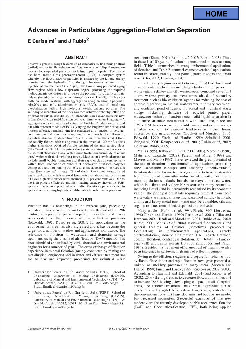
The FGR was designed and constructed for floc generation aheadof the solid-liquid or liquid-liquid separation stage with feedrates ranging from 012 to 06 m3h-1 (2 to 10 Lmin-1) Thesemi-pilot scale FGR (Figure 1) was constructed with apolyurethane pipe with an inner diameter of 125 cm enrolling a
10 cm diameter polyvinyl chloride (PVC) column
416 Brisbane QLD 6 - 9 June 2005 Centenary of Flotation Symposium
E CARIacuteSSIMI and J RUBIO
Environment (solid-liquid solid-liquid-liquid or liquid-liquid separation)
bull Effluents generated in the ore flotation plants thickeners or gravimetric concentration of fines (cyclones spirals concentration tables)bull Treatment of organic compounds (solvent extraction plants) oils fats and dyes (agates)bull Treatment of effluent with heavy metals (Ag+1 Sn+2 As+3 Cr+3 Cr+6 Au+2 Au+4 Be+2 Cd+2 Co+2 Ga+2 Ge+4 Hg+2 Pb+2 Mn+2 Ni+2 Cu+2 Zn+2
Sb+3 Se+2) and anions (CN CrO4 S-2 AsO4 SO4 PO4 MoO4 F-1)bull Water recycle (filters) Anions and calcium ions removal andbull Treatment of acid mine drainage (AMD) and water reuse
Industrial processes
bull Proteins separationbull Removal of impurities in the sugar cane industrybull Separation of oils fats surfactants (soaps) odour removal and solids wastes in the food industrybull Plastics recycle pigments dyes and fibresbull Paper ink separation rubber resins printer toner pigmentsbull Emulsified oil removal in the chemical and petrochemical industrybull Thickening of activated sludge andbull Reuse (recycle) of industrial waters (PET washing of vehicles aeroplanes)
Others
bull Removal-separation of micro-organisms (algae fungal bacteria)bull Metals separation for analytical chemistrybull Treatment of soils pesticides removal oils and radioactive elementsbull Treatment of industrial waters in the corrosion control removal of soaps detergentsbull Treatment of waters for industrial and domestic use andbull Treatment of sewage (removal of biological flocs suspended solids)
TABLE 1Environmental applications (some) of flotation
DAF units Loadingcapacity (m3h-1)
Favela da Rocinhadagger ndash Rio de Janeiro (RJ) (sea pool) 1080
Lagoa da Aclimaccedilatildeodagger ndash Lagoon in Satildeo Paulo (SP) 180
Parque do Ibirapuera ndash SP (park lagoon) 540
Parque da Aclimaccedilatildeo ndash SP (park lagoon 180
Lagoa da Imboassicadagger ndash RJ (lagoon) 900
Piscinatildeo de Ramos (sea pool) 270
Rio NegroDagger ndash Amazonas ndash Manaus (MN) (river) 25 000
dagger Projects under implantationDagger Considered the biggest worldwide FAD treatment unit
TABLE 2Recent unconventional (lsquosea poolsrsquo rivers and parks lagoons)
DAF applications in Brazil
7232019 Advances in Particulates Aggregation-Flotation Separation
httpslidepdfcomreaderfulladvances-in-particulates-aggregation-flotation-separation 39
Four different reactor models with varying lengthvolumeratios were evaluated for the generation of the flocs The designcharacteristics and residence times are summarised in Table 3
The system rig used was composed of two tanks (capacity of 500 L each) for the Fe(OH)3 clay preparation and storage twohelical pumps a NestzschTM model 2NE30A to feed the in-line
mixing unit and a Nestzsch
TM
model 2NE15A to feed thesaturator vessel with tap waterThe feed rate was controlled by a WegTM frequency controlling
equipment model CFW 07 A ProvitecTM (model DMAS-AX-02)dosing peristaltic pump was used to inject the polymer andor theoil emulsion For the generation of the microbubbles (as in DAF)air was dissolved into water using a saturator vessel (height of 90 cm and 10 cm diameter) The saturator operating at varyingpressures (2 3 4 5 and 6 atm) was constructed with a bed heightof 50 cm filled with Pall rings
Methods
Flocculation experiments were carried out at room temperatureusing colloidal Fe(OH)3 dispersion formed from the FeCl36H2O
dissolution and subsequent precipitation with Ca(OH)2 at pH75plusmn05 (monitored with an AnalionTM pH meter model PM608) Mafloc 490CTM polymer was added in-line in the Fe(OH)3aqueous dispersion and pumped through the FGR for the flocsgeneration (aerated or non-aerated) Aggregation studies werealso carried out using a 3 gL-1 suspension of bentonite tosimulate the natural turbidity of raw waters and the aggregationwas evaluated using AH912SH (an anionic polymer) Al2(SO4)3and PAC An oil emulsion was prepared at room temperature(20degC) for the destabilisation studies and sodium lauryl ethersulfate was added in the emulsion prior destabilisation by Flonex9045TM polymer
The flow exiting from the FGR fed the solid-liquid separationvessels (columns) whereby the settling (non-aerated flocs) andrising (aerated flocs) rates were evaluated These rates werecalculated monitoring the times needed for the flocs to travel afixed distance Time measurements were made by direct
observation (randomly) of many individual flocs Flocculationefficiency was also monitored by measuring iron removal fromthe water (VarianTM atomic absorption spectrometer) theresidual iron concentration in the supernatants after flocculationand the turbidity removal (Hach turbidimeter model 2100) In allcases the degree of flocculation was higher than 95 per cent Oildestabilisation efficiency was measured through the residual oildetermined with a spectrophotometer GenesysTM 10 series at
300 nm Samples extraction of residual oil was followed by athree-stage gravimetric extraction of residual oil usingdichloromethane (110 vv) of analytical purity (NuclearTM)
The evaluation of the flocculation performance of the FGRand its optimisation were made by monitoring the separation rateof the flocs formed The criterion used (for optimal conditions)was the fastest separation rates either settling of non-aeratedflocs or rising time of the aerated ones For the oil emulsiondestabilisation efficiency the criteria was the largest fraction of oil removal
All experimental conditions were tested in triplicate with atleast 25 measurements of separation for each experimentalcondition An arithmetic mean of all the values obtained wascalculated and statistically analysed according to the analysis of variance (One-Way Anova) described in Montgomery (1991)
Studies with non-aerated flocs
In the measurements of the settling rate of non-aeratedaggregates one litre of sample exiting the FGR was introducedin a graduated cylinder The density of these aggregates wascalculated using Stokesrsquo law for laminar flux using the settlingrate data and the size of the flocs The latter was obtained fromphotographic analysis (SonyTM digital camera model DSC) andsized with a graduated scale (fixed at the same cylinder)
The mass fractal dimension of the Fe(OH)3 flocs was obtainedusing settling rate and size data obtained from settlingexperiments and through logarithmic correlation between themass and the size of the flocs considering spherical geometry(Gregory 1988 Gregory 1998 Tang et al 2002)
Studies with aerated flocs
In the experiments with aerated flocs microbubbles with sizesranging from 30 to 70 microm (Rodrigues and Rubio 2003) wereintroduced in the inlet of the FGR The air employed in thesaturator vessel was supplied by an air compressor and themicrobubbles were generated by the depressurisation of the airsaturated solution under controlled pressure through a nozzle(needle valve) in the same manner as in the DAF (Kiuru 2001Rubio et al 2001) The injection of the microbubbles into theFGR is followed by entrainment andor entrapment of thesebubbles onto (or into) the Fe(OH)3 polymer flocs or claypolymer flocs forming the aerated units
The solid-liquid separation of these floating flocs was
measured monitoring the rising times in a graduated cylindricalcolumn
Centenary of Flotation Symposium Brisbane QLD 6 - 9 June 2005 417
ADVANCES IN PARTICULATES AGGREGATION-FLOTATION SEPARATION
inlet
effluent + polymer
air
microbubbles
length
outer
diameter
exit
flow direction
FIG 1 - Flocs generator reactor (FGR) unit
Reactor Number of rings Length (m) Volume (L) Residence time (s)
2 Lmin-1 3 Lmin-1 4 Lmin-1 5 Lmin-1
FGR 1 16 6 06 180 120 90 72
FGR 2 32 12 12 360 240 180 144
FGR 3 48 18 18 540 360 270 216
FGR 4 64 24 24 720 480 360 288
TABLE 3Design parameters and residence times of the FGR reactors
7232019 Advances in Particulates Aggregation-Flotation Separation
httpslidepdfcomreaderfulladvances-in-particulates-aggregation-flotation-separation 49
Studies of the effect of the airsolids ratio on the separationefficiency were conducted fixing the ratio of injectedmicrobubbles at ten per cent and varying the saturation pressure(2 3 4 5 and 6 atmospheres) The calculation of the airsolidsratio was made using the following Equation 1
as Ri Av
FR solS =
[ ] (1)
where
as = airsolids ratio (mlmg-1)
Ri = rate of injection of microbubbles (Lmin-1)
Av = theoretical volume of dissolved air per litre of wateraccording to the Henry law (mlL-1)
FR = feed rate (Lmin-1)
S = saturator vessel efficiency (per cent)
Oil-in-water emulsion destabilisation
An 100 mgL-1 oil emulsion was prepared at room temperature
(20degC) for the destabilisation studies using a Turrax mixer at11 000 rpm during 15 minutes One mgL -1 of sodium lauryl ethersulfate was added to the emulsion prior to destabilisation withthe in-line injection of Flonex 9045TM polymer (5 10 20 30 40and 50 mgL-1) Oil destabilisation efficiency was measuredthrough the residual oil determined with a spectrophotometerStudies were carried out using the FGR 2 with a 3 Lmin -1 feedrate (residence time of 24 s)
RESULTS AND DISCUSSION
The formation of aggregates in the FGR and theirsettling rate
Fe(OH) 3 polymer flocs
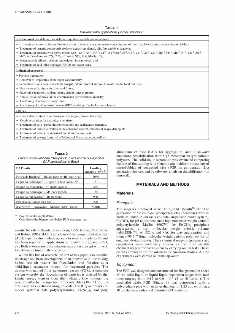
The effect of the reactor type and the feed rate on the settling rateof the flocs generated is shown in Figure 2 Formation andgrowth of the Fe(OH)3 flocs is shown in Figure 3 (flow directionleft to right)
For all the reactors types the highest settling rates ranged from12 to 19 mh-1 showing an optimal for a feed rate of 4 Lmin-1 (orequivalent residence times as shown in Table 3) At the lowerfeed rates (2 Lmin-1) the low efficiency may be due to the lowturbulence in forming the flocs especially with high molecularweight polymeric flocculants such as the Mafloc 490CTM (Weirand Moody 2003) For the very high feed rates the systemturbulence contributed to the rupture of the flocs decreasing thesettling rate Following the results obtained the FGR 2 whichshowed the highest settling rates (19 mh-1) and yielded largeflocs (4 - 8 mm) was selected for further investigation
Clay aggregates
The aggregation of a clay suspension using an anionic polymeraluminium sulfate and PAC was evaluated in the FRG 2 (bestmodel) Figures 4 5 and 6 show clay aggregate settling ratesusing different concentrations of polymer Al2(SO4)3 and PACrespectively Figure 4 shows that low polymer dosages (025 and05 mgL-1) are efficient at producing good flocs and high settlingrates reaching as high as 17 mh-1 at 05 mgL-1 polymerconcentration Higher polymer dosages do not contribute tohigher settling rates following the usual polymer flocculationtrend at high concentrations
The settling rate of the clay particles is shown in Figure 5 fordifferent Al2(SO4)3 dosages at pH 65 (optimal coagulation pH)whereby Al(OH)3 is the main alum form present Results showthat the settling rate of the bentonite particles is higher for thehigher coagulant dosages in the FGR with settling rates of about6 mh-1 for 60 mgL-1 aluminium concentration
The settling rate of the clay particles using different PACconcentrations is shown in Figure 6 Results show that the lowerthe PAC dosages the higher the settling rates reaching values of
approximately 9 mh-1
for a 025 mgL-1
418 Brisbane QLD 6 - 9 June 2005 Centenary of Flotation Symposium
E CARIacuteSSIMI and J RUBIO
8
10
12
14
16
18
20
S e t t l i n g R a t e m h -
2 4 6
Feed Rate Lmin-1
FGR 1
FGR 2
FGR 3
FGR 4
FIG 2 - Fe(OH)3 flocs settling rate as a function of feed rate and
FGR model Conditions [Fe(OH)3] = 58 mgL-1
[Mafloc 490C] =
5 mgL-1
pH 75plusmn05
125 mm
FIG 3 - Fe(OH)3 flocs formation and growth through the FGR
(flow direction left to right)
2
4
6
8
10
12
14
16
18
S e t t l i n g R a t e m h - 1
025 05 1 2 4
[Anionic Polymer] mgL -1
FIG 4 - Clay flocs settling rate as a function of [AH912SH] polymer
concentration Conditions [Bentonite] = 03 gL-1
natural pH asymp 70
FGR 2 feed rate = 3 Lmin-1
Turbidity removal gt 96 per cent
7232019 Advances in Particulates Aggregation-Flotation Separation
httpslidepdfcomreaderfulladvances-in-particulates-aggregation-flotation-separation 59
Figure 7 shows the effect of the feed rate and residence timeon the flocs settling rates Results show that an increase in theinlet flow rate decreases the settling rate of the flocs generatedThis may be attributed to the high turbulence (determined by thesystem hydrodynamic conditions) which led to rupture of theformed flocs in the reactor Other authors (Akers et al 1987)have already investigated the effect of turbulent conditions intubular systems by observing the rupture of the flocs generatedusing small latex particles (097 microm) According to these authorsthe rupture of the flocs is highly dependent on the level of thedissipated turbulent energy Moreover the density distribution of the flocs or the conditions under which these flocs are formedmay interfere in their resistance to breakage
Figure 7 also shows the increase in the flocs settling rates withincrease in residence time The results show that for a residencetime up to 10 s the increase in settling rate is not as meaningfulas for times higher than 10 s This is probably due to fastpolymer adsorption onto the particles promoted by turbulence inthe FGR According to Weber (1972) polymer adsorption onto
particles is rapid and irreversible
Flocs characterisation
The results of physical characterisation of the Fe(OH)3 flocsgenerated in the FGR are shown in Figures 8 and 9 Figure 8shows that the flocs density decreases considerably as the flocssize increases due the flocs fractal dimension as previouslydescribed by others (Klimpel and Hogg 1991 Adachi andTanaka 1997 Gregory 1997 Tang 2002) The average density of the Fe(OH)3 flocs generated in the reactor was 1019plusmn18 kgm-3 forflocs with sizes ranging from 400 and 2000 microm
The mass fractal dimension (dF) of the Fe(OH)3 flocs obtainedin this work is shown in Figure 9 The value obtained of dF(298) characterises a dense floc with low porosity and aspherical format Values of about three have been alreadyreported in the literature and were explained as a result of lineartrajectories yielding more compact and spherical structures alsocalled lsquoballisticrsquo aggregation which happens mainly in theparticle-cluster case of aggregation (Gregory 1997 Burns et al1997 Burns et al 1998)
The FGR because of its coiled design presents somepeculiarities among others a fairly high shear rate foraggregation a secondary flow and centrifugal (collision) forcesThese promote good contact between the high molecular weightpolymer and the colloidal particles thus forming strong big
and compact structures According to Gregory (1981) the
Centenary of Flotation Symposium Brisbane QLD 6 - 9 June 2005 419
ADVANCES IN PARTICULATES AGGREGATION-FLOTATION SEPARATION
0
1
2
3
4
5
6
7
S e t t l i n g
R a t e m h - 1
10 20 30 40 50 60
[Al2(SO4)3] mgL-1
FIG 5 - Clay flocs settling rate as a function of the Al2(SO4)3concentration Conditions [Bentonite] = 03 gL
-1 pH asymp 65 FGR 2
feed rate = 3 Lmin-1
Turbidity removal gt 80 per cent
5
6
7
8
9
10
S e t t l i n g R a t e m h - 1
01 025 05 075 1
[PAC] mLL-1
FIG 6 - Clay flocs settling rate as a function of PAC concentration
Conditions [Bentonite] = 03 gL-1
natural pH asymp 70 FGR 2 feed
rate = 3 Lmin-1
Turbidity removal gt 98 per cent
0
2
4
6
8
10
12
4 7 10 13 16 19
Settling Rate mh-1
F e e d R a t e L m i n - 1
0
5
10
15
20
25
30
R e s i d e n c e T i m e s
Feed Rate
Residence Time
FIG 7 - Settling rate of the flocs as a function of the feed rate and
residence time Conditions [Fe(OH)3] = 58 mgL-1
[Mafloc 490C] =
5 mgL-1
FGR 2
1000
1010
1020
1030
1040
0 500 1000 1500 2000 2500
Flocs Size microm
F l o c s D e n s i t y
k g m - 3
FIG 8 - Density of the flocs as a function of Fe(OH)3 flocs size
Conditions [Fe(OH)3] = 58 mgL-1
FGR 2 pH 75plusmn05
7232019 Advances in Particulates Aggregation-Flotation Separation
httpslidepdfcomreaderfulladvances-in-particulates-aggregation-flotation-separation 69
secondary flow introduced by the coiled tubes may affectflocculation in several ways most notably there would be anincrease in the pressure drop across the tube for a given flow ratecausing an increased average shear rate inside the tube improvingthe flocculation Besides the significant advantages presented byin-line mixing (Cariacutessimi and Rubio 2005) it may be betterexplored by winding the tubes into a helical coil The resultsappear to be shorter and more compact tube lsquoflocculatorsrsquo
The formation of aerated flocs and their flotation
In this system not only is flocculation favoured (due to higherturbulence) but also entrainment andor entrapment(enmeshment) of air bubbles inside the flocs leading toformation of large aerated units This phenomenon was observedvisually and is represented schematically in Figure 10 Theaerated flocs lsquofloatrsquo and are easily separated as a flotationproduct (named here as floc-flotation) Therefore the FGR in
this case serves at the same time as a flocculator and as abubblefloc contactor
Fe(OH) 3 polymer flocs
The effect of the reactor type was again evaluated through thedetermination of the flocs rising rates using the techniquedescribed (results are shown in Figure 11)
In all reactors the highest rising rates were obtained at a feedrate of 2 Lmin-1 with rates ranging from 67 to 112 mh-1 For feedrates above 2 Lmin-1 there was a decrease in the rising rate due tothe increase in turbulence caused by the increase of the inlet flowrate and the injection of microbubbles However using FGR 2the difference in the rising rates of the flocs for the feed rates
investigated is not so meaningful
FGR 2 presented the best results in terms of floc rising rate
(112 mh-1) and this reactor was chosen for further tests FGR 1showed poor efficiency due the short length which did not allowa sufficient residence time for floc formation FGRs 3 and 4presented a decrease in the rising rates probably due to ruptureof the flocs at all feed rates As previously mentioned flocs donot continue to grow indefinitely during prolonged shear butattain an equilibrium size
The variation of the flocs rising velocity according to theairsolids ratio is shown in Figure 12
Figure 12 shows that best results are obtained with anairsolids ratio greater than 0025 mlmg-1 Previous studies of flotation of colloidal hydroxide iron flocs showed iron removalefficiencies greater than 80 per cent with an airsolids ratio of 05(Shannon and Buisson 1980) Results obtained in this work atlower airsolids ratio may be explained in terms of increasedefficiency of collision adhesion attachment and entrapment of the bubbles inside or onto the flocs which does not occur in theconventional process of DAF According to Purchas (1977) theairsolids ratio is more related to the amount of air precipitatedand not to the quantity of air bubbles actually adhering to thefloating particles Thus the results obtained validate thefunctioning of the FGR as a bubbleparticle contactor enablingthe use of airsolids ratios much lower than those utilised in
conventional processes
420 Brisbane QLD 6 - 9 June 2005 Centenary of Flotation Symposium
E CARIacuteSSIMI and J RUBIO
Polymer
Effluent
Exit
Aerated FlocsPolymer
Air Microbubbles
Solids
Air
FIG 10 - Generation and growing of aerated flocs inside the FGR
85
90
95
100
105
110
115
R i s e R a t e m h -
2 4 6
Feed Rate Lmin-1
FGR 1
FGR 2
FGR 3
FGR 4
FIG 11 - Rise rate of the flocs as a function of feed rate and FGR
type Conditions [Fe(OH)3] = 58 mgL-1
[Mafloc 490C] = 5 mgL-1
air injection ratio = 50 per cent saturation pressure = 4 atm pH
75plusmn05
dF = 29828
1
2
3
4
25 27 29 31 33 35
log (flocs size)
l o g
( f l o c s m a s s )
FIG 9 - Fractal dimension of Fe(OH)3 flocs Conditions [Fe(OH)3] =
58 mgL-1
[Mafloc 490C] = 5 mgL-1
FGR 2 pH 75plusmn05
25
50
75
100
5
001 0015 002 0025 003 0035 004
Airsolids Ratio mLmg-1
R i s e R a t e m
h - 1
FIG 12 - Rise rate of the flocs as a function of the airsolids ratio
Conditions [Mafloc 490C] = 5 mgL-1
FGR 2 pH 75plusmn05
7232019 Advances in Particulates Aggregation-Flotation Separation
httpslidepdfcomreaderfulladvances-in-particulates-aggregation-flotation-separation 79
Comparative results obtained in this work revealed that theaerated separation rates are of the order of six times higher thanthe flocs settling rates The floating rates of the aerated flocsreaching values greater than 100 mh-1 are the result of the airvolume inside the floc structure plus the volume given by theadhered bubbles at the flocwater interface Accordinglycalculations of the equivalent diameter of bubbles which wouldgive such a rising rate were made and compared to the rising
(floating) flocs formed in the FGR (Figure 13)
The diameter of the equivalent bubbles calculated from theStokes equation for the rise rates of 67 to 112 mh-1 yielded anair bubble size (diameter) between 185 to 240 microm Because themicrobubbles injected measured experimentally (Rodrigues andRubio 2003) between 30 and 70 microm the only explanation forthis phenomenon is the air volume in the flocs Moreover thesevalues when compared to conventional DAF are much highermeaning that using the FGR as bubbles-flocs contactor may lead
to a very high capacity flotation system Some authors (Da Rosa2001 Rubio et al 2001 Haarhoff and Edzwald 2001) explainthe high rise rate in terms of the probability of bubble formationand rapid occlusion (entrapment) within flocs nucleation of bubbles at flocwater interfaces polymer coiling as a result of lsquosalting outrsquo effects at the aqueousair interface and plug flowmixing
Clay aerated aggregates
The rising rates of the aerated clay flocs using different dosagesof an anionic polyacrylamide are shown in Figure 14 Theconcentration of 05 mgL-1 showed the best rise results reachingvalues in the order of 115 mh-1 Results showed that higherpolymer doses are not efficient to increase the rise rate of the
clay flocs Overdose of the reagent (up to 05 mgL -1) reversed thesuperficial charge of the particles and prejudiced its aggregationThe rising rates of the aerated clay aggregates for different
doses of Al2(SO4)3 are shown in Figure 15 The best rise velocity(88 mh-1) is shown for the highest coagulant dosage (60 mgL -1)At high coagulant doses a higher concentration of Al(OH)3precipitates will be formed (pH 65) and the enmeshment of clayparticles by the precipitates and by the microbubbles will favourturbidity reduction
The rising rates of the aerated clay aggregates for differentdoses of PAC are shown in Figure 16 Results show that forhigher PAC doses the rising rate of the aggregates decreases Thelower PAC dose (025 mlL-1) showed the best rising velocity(98 mh-1) The rising rate probably decreases for higher PACdosages due to the large quantity of precipitates that aregenerated at these high reagent doses
Oil-in-water emulsion destabilisation
Destabilisation of a diesel oil emulsion employing Flonex 9045TM
polymer is shown in Figure 17 Results show that even the lower
dosage of the polymer flocculant (5 mgL-1) is enough todestabilise the emulsion with oil removal efficiencies reaching 90per cent Residual oil concentrations were about 6 - 9 mgL-1
In this case the effect of flocculation on the destabilisation of the oil emulsion was through the high turbulence promoted bythe FGR with velocity gradients up to 1400 s-1 (for a 3 Lmin-1
feed rate) (Cariacutessimi and Rubio 2005) The sodium lauryl ethersulfate surfactant used prior to the cationic polyacrylamideaddition allowed better oil removal results with low polymerdosages (Palanuwech and Coupland 2003)
CONCLUSIONS
An innovative in-line flocculation lsquohelicalrsquo unit named flocsgenerator reactor (FGR) was developed for the generation of
polymeric (aerated and non-aerated) flocs and oil-in-water
Centenary of Flotation Symposium Brisbane QLD 6 - 9 June 2005 421
ADVANCES IN PARTICULATES AGGREGATION-FLOTATION SEPARATION
180
200
220
240
65 75 85 95 105 115
Rise Rate mh -1
E q u i v a l e n t D i a m e t e r
m micro
FIG 13 - Equivalent diameter of bubbles as a function of the rise
rate (values obtained with the aerated flocs)
60
70
80
90
100
110
120
R i s e R
a t e m h -
025 05 1 2 4 6 8
[Anionic Polymer] mgL-1
FIG 14 - Clay rise rate as a function of [AH912SH] polymer
concentration Conditions [Bentonite] = 03 gL-1
natural pH asymp 70
FGR 2 feed rate = 3 Lmin-1
air injection ratio = 50 per cent
saturation pressure = 4 atm turbidity removal gt 88 per cent
60
65
70
75
80
85
90
R i s e R a t e m h - 1
10 20 30 40 50 60
[Al2(SO4)3] mgL-1
FIG 15 - Clay rise rate as a function of Al2(SO4)3 concentration
Conditions [Bentonite] = 03 gL-1
pH asymp 65 FGR 2 feed rate =
3 Lmin-1
air injection ratio = 50 per cent saturation pressure =
4 atm turbidity removal gt93 per cent
7232019 Advances in Particulates Aggregation-Flotation Separation
httpslidepdfcomreaderfulladvances-in-particulates-aggregation-flotation-separation 89
destabilisation The studies showed high efficiency for thegeneration of Fe(OH)3 and clay flocs with the employment of high molecular weight polymers The polymer flocs obtainedwere well structured large and the Fe(OH)3 flocs presented afractal dimension of 298 characteristic of dense flocs with lowporosity and spherical format The FGR may also be used as afloc-bubble contactor to generate large aerated flocs (5 - 8 mm)
The FGR appears to have some advantages for the formation of polymer flocs namely suitable flow mixing absence of short-circuits or dead zones plug flow profile low arearequirement absence of moving parts simple design and lowmechanical and electrical energy needs Solid-liquid separationof the flocs by settling reached rates of about 18 - 24 mh-1
compared to more than 100 mh-1 rise rate for aerated flocs Thesevalues are higher than those found in conventional sedimentationor DAF units The FGR appears to have good potential as alsquoflocculatorrsquo (or flotation)-separator device in applicationsrequiring high rate solid-liquid separations Successful examplesof emulsified oil and solids removal from water were shown andbecause in all cases efficiencies were high (gt90 per centremoval) it is believed that this kind of flocculation-flotationappears to have a great potential in solid-liquid or liquid-liquid
separation
ACKNOWLEDGEMENTS
The authors thank all the colleagues at Laboratoacuterio deTecnologia Mineral e Ambiental (LTM) at UFRGS for theirassistance and friendly atmosphere and to all institutionssupporting research in Brazil especially CNPq (Institute of Millennium Project)
REFERENCESAdachi Y and Tanaka Y 1997 Settling velocity of an aluminium-kaolinit
floc Water Science and Technology 31(3)449-454Bio 2002 Flotaccedilatildeo ganha adeptos no Brasil Revista Brasileira de
Saneamento e Meio Ambiente JulySeptember pp 40-47 (inPortuguese)
Burns J L Yan Y D Jameson G J and Biggs S A 1997 A lightscattering study of the fractal aggregation behavior of a modelcolloidal system Langmuir 136413-6420
Burns J L Yan Y D Jameson G J and Biggs S A 1998 A comparisonof the fractal properties of salt-aggregated and polymer-flocculatedcolloidal particles Progress in Colloid and Polymer Science11070-75
Cariacutessimi E and Rubio J 2005 The flocs generator reactor ndash FGR anew basis for flocculation and solid-liquid separation International Journal of Mineral Processing 75(3-4)237-247
Costa C A and Rubio J 2005 Deinking flotation influence of calciumsoap and surface-active substances Minerals Engineering18(1)59-64
Crockett J and Muntisov M 1995 Potable water treatment by dissolvedair flotationfiltration in Proceedings Modern Techniques in Water and Wastewater Treatment (eds L O Kolarik and A J Priestley) pp15-18
Da Rosa J J 2001 Tratamento de efluentes oleosos por floculaccedilatildeopneumaacutetica em linha e separaccedilatildeo por flotaccedilatildeo Processo FF ThesisUFRGSPPGEM Jorge Rubio 126 p (in Portuguese)
Edzwald J K 1995 Principles and applications of dissolved air flotationWater Science and Technology 31(3-4)1-23
Feacuteris L A Gallina C W Rodrigues R T and Rubio J 2001 Optimizingdissolved air flotation design and saturation Water Science and Technology 43(8)153-157
Filho A C T P and Brandno C C S 2001 Evaluation of flocculation anddissolved air flotation as an advanced wastewater treatment Water Science and Technology 43(8)91-98
Finch J A 1995 Column flotation a selected review-part IV flotationdevices Minerals Engineering 8(6)587-602
Finch J A and Hardie C A 1999 An example of innovation from thewaste management industry deinking flotation cells Minerals Engineering 12(5)467-475
Gregory J 1981 Flocculation in laminar tube flow Chemical Engineering Science 36(11)1789-1794
Gregory J 1988 Polymer adsorption and flocculation in shearedsuspensions Colloids and Surfaces 31231-253
Gregory J 1997 The density of particle aggregates Water Science and Technology 36(4)1-13
Gregory J 1998 The role of floc density in solid-liquid separationFiltration and Separation 35(4)367-371
Haarhoff J and Edzwald J K 2001 Modelling of floc-bubble aggregaterise rates in dissolved air flotation Water Science and Technology43(8)175-184
Harbort G J Jackson B R and Manlapig E V 1994 Recent advances inJameson flotation cell technology Minerals Engineering7(2-3)319-332
Kempeneers S Menxel F V and Gille L 2001 A decade of largeexperience in dissolved air flotation Water Science and Technology43(8)35-41
Kiuru H J 2001 Development of dissolved air flotation technology fromthe first generation to the newest (third) one (DAF in turbulent flowconditions) Water Science and Technology 43(8)1-7
Klimpel R C and Hogg R 1991 Evaluation of floc structures Colloidsand Surfaces 55279-288
Liers S Baeyens J and Mochtar I 1996 Modelling dissolved airflotation Water Environment Research 68(6)1061-1075
422 Brisbane QLD 6 - 9 June 2005 Centenary of Flotation Symposium
E CARIacuteSSIMI and J RUBIO
0
20
40
60
80
100
0 20 40 60
[Cationic Polymer] mgL-1
O i l r e m o v a l
0
20
40
60
80
100
O i l R e s i d u a l m g L - 1
Oil Removal
Oil Residual
FIG 17 - Diesel oil emulsion flocculation (destabilisation) with
Flonex 9045 polymer Conditions [ow emulsion] = 100 mgL-1
[sodium lauryl ether sulfate] = 1 mgL-1
temperature = 20degC FGR
2 feed rate = 3 Lmin-1
80
85
90
95
100
R i s e R a t e m h - 1
01 025 05 075 1
[PAC] mLL-1
FIG 16 - Clay rise rates as a function of the PAC concentration
Conditions [Bentonite] = 03 gL-1
natural pH asymp 70 FGR 2 feed
rate = 3 Lmin-1
air injection ratio = 50 per cent saturation
pressure = 4 atm turbidity removal gt98 per cent
7232019 Advances in Particulates Aggregation-Flotation Separation
httpslidepdfcomreaderfulladvances-in-particulates-aggregation-flotation-separation 99
Matis K A and Lazaridis N K 2002 Flotation techniques in watertechnology for metals recovery dispersed-air versus dissolved-airflotation J Min Metall A381-27
Matis K A 1995 Flotation Science and Engineering 584 p (MarcelDekker New York)
Matis K A Zouboulis A I Gallios G P Erwe T and Bloumlcher C 2004Application of flotation for the separation of metal-loaded zeolitesChemosphere 5565-72
Mavros P and Matis K A (eds) 1992 Innovations in Flotation
Technology (Kluwer Academic Publishers Dordrecht)Montgomery D C 1991 Design and Analysis of Experiments third
edition 649 p (John Wiley and Sons Inc Canada)Oslashdegaard H 2001 The use of dissolved air flotation in municipal
wastewater treatment Water Science and Technology 43(8)83-90Oliveira J C 2004 Tecnologia para despoluir o rio Pinheiros
Saneamento Ambiental 10868 (in Portuguese)Owen J J Morse D E Morse W O and Jovine R 1999 New
developments in flotation equipment for water treatment systems in Advances in Flotation Technology (eds B K Parekh and J D Miller)pp 381-389 (Society for Mining Metallurgy and Exploration Inc(SME) Littleton)
Palanuweck J and Coupland J N 2003 Effect of surfactant type on thestability of oil-in-water emulsions to dispersed phase crystallizationColloids and Surfaces A Physicochemical and Engineering Aspects223251-262
Parekh B K and Miller J D (eds) 1999 Advances in FlotationTechnology (Society for Mining Metallurgy and Exploration Inc(SME) Littleton)
Purchas D B 1977 SolidLiquid Separation Equipment Scale Up 584 p(Upland Press Ltd)
Reali M A P and Marchetto M 2001 High-rate dissolved air flotationfor water treatment Water Science and Technology 43(8)51-57
Rodrigues R T and Rubio J 2003 New basis for measuring the sizedistribution of bubbles Minerals Engineering 16757-765
Rosa J J and Rubio J 2005 The FF (flocculation-flotation) process Minerals Engineering 18(7)701-707
Rubio J 1998 Environmental applications of the flotation process in Effluent Treatment in the Mining Industry (eds S H Castro F Vergaraand M Sanchez) Chapter 8 pp 335-364 (University of Concepcioacuten-Chile Chile)
Rubio J 2003 Unconventional flocculation and flotation in ProceedingsFlotation and Flocculation From Fundamentals to ApplicationsStrategic Conference and Workshop Hawaii (eds J Ralston J Miller
and J Rubio) pp 17-32Rubio J Souza M L and Smith R W 2002 Overview of flotation as a
wastewater treatment technique Minerals Engineering 15139-155Rubio J Tessele F Porcile P A and Marinkovic E 2001 Flotacioacuten
como proceso de remocioacuten de contaminantes I Principios baacutesicosteacutecnicas y aplicaciones Minerales 56(242)9-18 (in Spanish)
Schofield T 2001 Dissolved air flotation in drinking water productionWater Science and Technology 43(8)9-18
Shannon W T and Buisson D H 1980 Dissolved air flotation in hotwater Water Research 14(7)759-765
Tang P Greenwood J and Raper A 2002 A model to describe thesettling behavior or fractal aggregates Journal of Colloid and Interface Science 247210-219
Voronin N N and Dibrov I A 1998 Classification of flotation processesin wastewater decontamination Journal of Environmental Engineering 124(5)469-472
Weber W J 1972 Physicochemical Processes for Water Quality Control640 p (Wiley-Interscience New York-USA)
Weir S and Moody G M 2003 The importance of flocculant choice withconsideration to mixing energy to achieve efficient solidliquidseparation Minerals Engineering 16(2)109-113
Zhou Z A Zhenghe Xu and Finch J A 1994 On the role of cavitationin particle collection during flotation ndash a critical review Minerals Engineering 7(9)1073-1084
Centenary of Flotation Symposium Brisbane QLD 6 - 9 June 2005 423
ADVANCES IN PARTICULATES AGGREGATION-FLOTATION SEPARATION
7232019 Advances in Particulates Aggregation-Flotation Separation
httpslidepdfcomreaderfulladvances-in-particulates-aggregation-flotation-separation 29
mainly for oily effluents (Owen et al 1999 Rubio 2003 Rosa
and Rubio 2005) BAF is an advanced air sparged hydrocyclone(ASH) type flotation which appears to work similarly to FF andhas been reported in applications to remove oil grease BODetc Both systems use the contactor-separation concept with verylow detention times in the contactor
Within this line of research the aim of this paper is to describethe design and basic development of an innovative in-line mixinghelical (coiled) reactor for flocculation and flotation as asolid-liquid separation process for suspended particles Thedevice was named flocs generator reactor (FGR) a compactsystem whereby the flocculation of particles is assisted by thekinetic energy transfer from the hydraulic flow through thereactor andor by the injection of microbubbles (30 - 70 microm) Itsefficiency was evaluated using colloidal Fe(OH)3 and clays (as
model systems) with polyacrylamides Al2(SO4)3 and poly
aluminium chloride (PAC) for aggregation and oil-in-wateremulsions destabilisation with high molecular weight cationicpolymers The solid-liquid separation was evaluated comparingthe rate of floc settling with flotation after addition (injection) of microbubbles of controlled size (FGR as an aerated flocsgeneration device) and by oilwater emulsion destabilisation (oil
removal)
MATERIALS AND METHODS
Materials
Reagents
The reagents employed were FeCl36H2O (SynthTM) for thegeneration of the colloidal precipitates clay (bentonite) with allparticles under 25 microm (as a colloidal suspension model system)Ca(OH)2 for pH adjustment and a high molecular weight cationicpolyacrylamide (Mafloc 490CTM) for Fe(OH)3 precipitateaggregation a high molecular weight anionic polymer
(AH912SHTM
) Al2(SO4)3 and PAC for clay aggregation andFlonex 9045TM (high molecular weight cationic polymer) for oilemulsion destabilisation These chemical reagents (polymers andcoagulants) were previously chosen as the most suitablechemical reagent for each system by carrying out jar tests Dieseloil was employed for the oil-in-water emulsion studies All theexperiments were carried out with tap water
Equipment
The FGR was designed and constructed for floc generation aheadof the solid-liquid or liquid-liquid separation stage with feedrates ranging from 012 to 06 m3h-1 (2 to 10 Lmin-1) Thesemi-pilot scale FGR (Figure 1) was constructed with apolyurethane pipe with an inner diameter of 125 cm enrolling a
10 cm diameter polyvinyl chloride (PVC) column
416 Brisbane QLD 6 - 9 June 2005 Centenary of Flotation Symposium
E CARIacuteSSIMI and J RUBIO
Environment (solid-liquid solid-liquid-liquid or liquid-liquid separation)
bull Effluents generated in the ore flotation plants thickeners or gravimetric concentration of fines (cyclones spirals concentration tables)bull Treatment of organic compounds (solvent extraction plants) oils fats and dyes (agates)bull Treatment of effluent with heavy metals (Ag+1 Sn+2 As+3 Cr+3 Cr+6 Au+2 Au+4 Be+2 Cd+2 Co+2 Ga+2 Ge+4 Hg+2 Pb+2 Mn+2 Ni+2 Cu+2 Zn+2
Sb+3 Se+2) and anions (CN CrO4 S-2 AsO4 SO4 PO4 MoO4 F-1)bull Water recycle (filters) Anions and calcium ions removal andbull Treatment of acid mine drainage (AMD) and water reuse
Industrial processes
bull Proteins separationbull Removal of impurities in the sugar cane industrybull Separation of oils fats surfactants (soaps) odour removal and solids wastes in the food industrybull Plastics recycle pigments dyes and fibresbull Paper ink separation rubber resins printer toner pigmentsbull Emulsified oil removal in the chemical and petrochemical industrybull Thickening of activated sludge andbull Reuse (recycle) of industrial waters (PET washing of vehicles aeroplanes)
Others
bull Removal-separation of micro-organisms (algae fungal bacteria)bull Metals separation for analytical chemistrybull Treatment of soils pesticides removal oils and radioactive elementsbull Treatment of industrial waters in the corrosion control removal of soaps detergentsbull Treatment of waters for industrial and domestic use andbull Treatment of sewage (removal of biological flocs suspended solids)
TABLE 1Environmental applications (some) of flotation
DAF units Loadingcapacity (m3h-1)
Favela da Rocinhadagger ndash Rio de Janeiro (RJ) (sea pool) 1080
Lagoa da Aclimaccedilatildeodagger ndash Lagoon in Satildeo Paulo (SP) 180
Parque do Ibirapuera ndash SP (park lagoon) 540
Parque da Aclimaccedilatildeo ndash SP (park lagoon 180
Lagoa da Imboassicadagger ndash RJ (lagoon) 900
Piscinatildeo de Ramos (sea pool) 270
Rio NegroDagger ndash Amazonas ndash Manaus (MN) (river) 25 000
dagger Projects under implantationDagger Considered the biggest worldwide FAD treatment unit
TABLE 2Recent unconventional (lsquosea poolsrsquo rivers and parks lagoons)
DAF applications in Brazil
7232019 Advances in Particulates Aggregation-Flotation Separation
httpslidepdfcomreaderfulladvances-in-particulates-aggregation-flotation-separation 39
Four different reactor models with varying lengthvolumeratios were evaluated for the generation of the flocs The designcharacteristics and residence times are summarised in Table 3
The system rig used was composed of two tanks (capacity of 500 L each) for the Fe(OH)3 clay preparation and storage twohelical pumps a NestzschTM model 2NE30A to feed the in-line
mixing unit and a Nestzsch
TM
model 2NE15A to feed thesaturator vessel with tap waterThe feed rate was controlled by a WegTM frequency controlling
equipment model CFW 07 A ProvitecTM (model DMAS-AX-02)dosing peristaltic pump was used to inject the polymer andor theoil emulsion For the generation of the microbubbles (as in DAF)air was dissolved into water using a saturator vessel (height of 90 cm and 10 cm diameter) The saturator operating at varyingpressures (2 3 4 5 and 6 atm) was constructed with a bed heightof 50 cm filled with Pall rings
Methods
Flocculation experiments were carried out at room temperatureusing colloidal Fe(OH)3 dispersion formed from the FeCl36H2O
dissolution and subsequent precipitation with Ca(OH)2 at pH75plusmn05 (monitored with an AnalionTM pH meter model PM608) Mafloc 490CTM polymer was added in-line in the Fe(OH)3aqueous dispersion and pumped through the FGR for the flocsgeneration (aerated or non-aerated) Aggregation studies werealso carried out using a 3 gL-1 suspension of bentonite tosimulate the natural turbidity of raw waters and the aggregationwas evaluated using AH912SH (an anionic polymer) Al2(SO4)3and PAC An oil emulsion was prepared at room temperature(20degC) for the destabilisation studies and sodium lauryl ethersulfate was added in the emulsion prior destabilisation by Flonex9045TM polymer
The flow exiting from the FGR fed the solid-liquid separationvessels (columns) whereby the settling (non-aerated flocs) andrising (aerated flocs) rates were evaluated These rates werecalculated monitoring the times needed for the flocs to travel afixed distance Time measurements were made by direct
observation (randomly) of many individual flocs Flocculationefficiency was also monitored by measuring iron removal fromthe water (VarianTM atomic absorption spectrometer) theresidual iron concentration in the supernatants after flocculationand the turbidity removal (Hach turbidimeter model 2100) In allcases the degree of flocculation was higher than 95 per cent Oildestabilisation efficiency was measured through the residual oildetermined with a spectrophotometer GenesysTM 10 series at
300 nm Samples extraction of residual oil was followed by athree-stage gravimetric extraction of residual oil usingdichloromethane (110 vv) of analytical purity (NuclearTM)
The evaluation of the flocculation performance of the FGRand its optimisation were made by monitoring the separation rateof the flocs formed The criterion used (for optimal conditions)was the fastest separation rates either settling of non-aeratedflocs or rising time of the aerated ones For the oil emulsiondestabilisation efficiency the criteria was the largest fraction of oil removal
All experimental conditions were tested in triplicate with atleast 25 measurements of separation for each experimentalcondition An arithmetic mean of all the values obtained wascalculated and statistically analysed according to the analysis of variance (One-Way Anova) described in Montgomery (1991)
Studies with non-aerated flocs
In the measurements of the settling rate of non-aeratedaggregates one litre of sample exiting the FGR was introducedin a graduated cylinder The density of these aggregates wascalculated using Stokesrsquo law for laminar flux using the settlingrate data and the size of the flocs The latter was obtained fromphotographic analysis (SonyTM digital camera model DSC) andsized with a graduated scale (fixed at the same cylinder)
The mass fractal dimension of the Fe(OH)3 flocs was obtainedusing settling rate and size data obtained from settlingexperiments and through logarithmic correlation between themass and the size of the flocs considering spherical geometry(Gregory 1988 Gregory 1998 Tang et al 2002)
Studies with aerated flocs
In the experiments with aerated flocs microbubbles with sizesranging from 30 to 70 microm (Rodrigues and Rubio 2003) wereintroduced in the inlet of the FGR The air employed in thesaturator vessel was supplied by an air compressor and themicrobubbles were generated by the depressurisation of the airsaturated solution under controlled pressure through a nozzle(needle valve) in the same manner as in the DAF (Kiuru 2001Rubio et al 2001) The injection of the microbubbles into theFGR is followed by entrainment andor entrapment of thesebubbles onto (or into) the Fe(OH)3 polymer flocs or claypolymer flocs forming the aerated units
The solid-liquid separation of these floating flocs was
measured monitoring the rising times in a graduated cylindricalcolumn
Centenary of Flotation Symposium Brisbane QLD 6 - 9 June 2005 417
ADVANCES IN PARTICULATES AGGREGATION-FLOTATION SEPARATION
inlet
effluent + polymer
air
microbubbles
length
outer
diameter
exit
flow direction
FIG 1 - Flocs generator reactor (FGR) unit
Reactor Number of rings Length (m) Volume (L) Residence time (s)
2 Lmin-1 3 Lmin-1 4 Lmin-1 5 Lmin-1
FGR 1 16 6 06 180 120 90 72
FGR 2 32 12 12 360 240 180 144
FGR 3 48 18 18 540 360 270 216
FGR 4 64 24 24 720 480 360 288
TABLE 3Design parameters and residence times of the FGR reactors
7232019 Advances in Particulates Aggregation-Flotation Separation
httpslidepdfcomreaderfulladvances-in-particulates-aggregation-flotation-separation 49
Studies of the effect of the airsolids ratio on the separationefficiency were conducted fixing the ratio of injectedmicrobubbles at ten per cent and varying the saturation pressure(2 3 4 5 and 6 atmospheres) The calculation of the airsolidsratio was made using the following Equation 1
as Ri Av
FR solS =
[ ] (1)
where
as = airsolids ratio (mlmg-1)
Ri = rate of injection of microbubbles (Lmin-1)
Av = theoretical volume of dissolved air per litre of wateraccording to the Henry law (mlL-1)
FR = feed rate (Lmin-1)
S = saturator vessel efficiency (per cent)
Oil-in-water emulsion destabilisation
An 100 mgL-1 oil emulsion was prepared at room temperature
(20degC) for the destabilisation studies using a Turrax mixer at11 000 rpm during 15 minutes One mgL -1 of sodium lauryl ethersulfate was added to the emulsion prior to destabilisation withthe in-line injection of Flonex 9045TM polymer (5 10 20 30 40and 50 mgL-1) Oil destabilisation efficiency was measuredthrough the residual oil determined with a spectrophotometerStudies were carried out using the FGR 2 with a 3 Lmin -1 feedrate (residence time of 24 s)
RESULTS AND DISCUSSION
The formation of aggregates in the FGR and theirsettling rate
Fe(OH) 3 polymer flocs
The effect of the reactor type and the feed rate on the settling rateof the flocs generated is shown in Figure 2 Formation andgrowth of the Fe(OH)3 flocs is shown in Figure 3 (flow directionleft to right)
For all the reactors types the highest settling rates ranged from12 to 19 mh-1 showing an optimal for a feed rate of 4 Lmin-1 (orequivalent residence times as shown in Table 3) At the lowerfeed rates (2 Lmin-1) the low efficiency may be due to the lowturbulence in forming the flocs especially with high molecularweight polymeric flocculants such as the Mafloc 490CTM (Weirand Moody 2003) For the very high feed rates the systemturbulence contributed to the rupture of the flocs decreasing thesettling rate Following the results obtained the FGR 2 whichshowed the highest settling rates (19 mh-1) and yielded largeflocs (4 - 8 mm) was selected for further investigation
Clay aggregates
The aggregation of a clay suspension using an anionic polymeraluminium sulfate and PAC was evaluated in the FRG 2 (bestmodel) Figures 4 5 and 6 show clay aggregate settling ratesusing different concentrations of polymer Al2(SO4)3 and PACrespectively Figure 4 shows that low polymer dosages (025 and05 mgL-1) are efficient at producing good flocs and high settlingrates reaching as high as 17 mh-1 at 05 mgL-1 polymerconcentration Higher polymer dosages do not contribute tohigher settling rates following the usual polymer flocculationtrend at high concentrations
The settling rate of the clay particles is shown in Figure 5 fordifferent Al2(SO4)3 dosages at pH 65 (optimal coagulation pH)whereby Al(OH)3 is the main alum form present Results showthat the settling rate of the bentonite particles is higher for thehigher coagulant dosages in the FGR with settling rates of about6 mh-1 for 60 mgL-1 aluminium concentration
The settling rate of the clay particles using different PACconcentrations is shown in Figure 6 Results show that the lowerthe PAC dosages the higher the settling rates reaching values of
approximately 9 mh-1
for a 025 mgL-1
418 Brisbane QLD 6 - 9 June 2005 Centenary of Flotation Symposium
E CARIacuteSSIMI and J RUBIO
8
10
12
14
16
18
20
S e t t l i n g R a t e m h -
2 4 6
Feed Rate Lmin-1
FGR 1
FGR 2
FGR 3
FGR 4
FIG 2 - Fe(OH)3 flocs settling rate as a function of feed rate and
FGR model Conditions [Fe(OH)3] = 58 mgL-1
[Mafloc 490C] =
5 mgL-1
pH 75plusmn05
125 mm
FIG 3 - Fe(OH)3 flocs formation and growth through the FGR
(flow direction left to right)
2
4
6
8
10
12
14
16
18
S e t t l i n g R a t e m h - 1
025 05 1 2 4
[Anionic Polymer] mgL -1
FIG 4 - Clay flocs settling rate as a function of [AH912SH] polymer
concentration Conditions [Bentonite] = 03 gL-1
natural pH asymp 70
FGR 2 feed rate = 3 Lmin-1
Turbidity removal gt 96 per cent
7232019 Advances in Particulates Aggregation-Flotation Separation
httpslidepdfcomreaderfulladvances-in-particulates-aggregation-flotation-separation 59
Figure 7 shows the effect of the feed rate and residence timeon the flocs settling rates Results show that an increase in theinlet flow rate decreases the settling rate of the flocs generatedThis may be attributed to the high turbulence (determined by thesystem hydrodynamic conditions) which led to rupture of theformed flocs in the reactor Other authors (Akers et al 1987)have already investigated the effect of turbulent conditions intubular systems by observing the rupture of the flocs generatedusing small latex particles (097 microm) According to these authorsthe rupture of the flocs is highly dependent on the level of thedissipated turbulent energy Moreover the density distribution of the flocs or the conditions under which these flocs are formedmay interfere in their resistance to breakage
Figure 7 also shows the increase in the flocs settling rates withincrease in residence time The results show that for a residencetime up to 10 s the increase in settling rate is not as meaningfulas for times higher than 10 s This is probably due to fastpolymer adsorption onto the particles promoted by turbulence inthe FGR According to Weber (1972) polymer adsorption onto
particles is rapid and irreversible
Flocs characterisation
The results of physical characterisation of the Fe(OH)3 flocsgenerated in the FGR are shown in Figures 8 and 9 Figure 8shows that the flocs density decreases considerably as the flocssize increases due the flocs fractal dimension as previouslydescribed by others (Klimpel and Hogg 1991 Adachi andTanaka 1997 Gregory 1997 Tang 2002) The average density of the Fe(OH)3 flocs generated in the reactor was 1019plusmn18 kgm-3 forflocs with sizes ranging from 400 and 2000 microm
The mass fractal dimension (dF) of the Fe(OH)3 flocs obtainedin this work is shown in Figure 9 The value obtained of dF(298) characterises a dense floc with low porosity and aspherical format Values of about three have been alreadyreported in the literature and were explained as a result of lineartrajectories yielding more compact and spherical structures alsocalled lsquoballisticrsquo aggregation which happens mainly in theparticle-cluster case of aggregation (Gregory 1997 Burns et al1997 Burns et al 1998)
The FGR because of its coiled design presents somepeculiarities among others a fairly high shear rate foraggregation a secondary flow and centrifugal (collision) forcesThese promote good contact between the high molecular weightpolymer and the colloidal particles thus forming strong big
and compact structures According to Gregory (1981) the
Centenary of Flotation Symposium Brisbane QLD 6 - 9 June 2005 419
ADVANCES IN PARTICULATES AGGREGATION-FLOTATION SEPARATION
0
1
2
3
4
5
6
7
S e t t l i n g
R a t e m h - 1
10 20 30 40 50 60
[Al2(SO4)3] mgL-1
FIG 5 - Clay flocs settling rate as a function of the Al2(SO4)3concentration Conditions [Bentonite] = 03 gL
-1 pH asymp 65 FGR 2
feed rate = 3 Lmin-1
Turbidity removal gt 80 per cent
5
6
7
8
9
10
S e t t l i n g R a t e m h - 1
01 025 05 075 1
[PAC] mLL-1
FIG 6 - Clay flocs settling rate as a function of PAC concentration
Conditions [Bentonite] = 03 gL-1
natural pH asymp 70 FGR 2 feed
rate = 3 Lmin-1
Turbidity removal gt 98 per cent
0
2
4
6
8
10
12
4 7 10 13 16 19
Settling Rate mh-1
F e e d R a t e L m i n - 1
0
5
10
15
20
25
30
R e s i d e n c e T i m e s
Feed Rate
Residence Time
FIG 7 - Settling rate of the flocs as a function of the feed rate and
residence time Conditions [Fe(OH)3] = 58 mgL-1
[Mafloc 490C] =
5 mgL-1
FGR 2
1000
1010
1020
1030
1040
0 500 1000 1500 2000 2500
Flocs Size microm
F l o c s D e n s i t y
k g m - 3
FIG 8 - Density of the flocs as a function of Fe(OH)3 flocs size
Conditions [Fe(OH)3] = 58 mgL-1
FGR 2 pH 75plusmn05
7232019 Advances in Particulates Aggregation-Flotation Separation
httpslidepdfcomreaderfulladvances-in-particulates-aggregation-flotation-separation 69
secondary flow introduced by the coiled tubes may affectflocculation in several ways most notably there would be anincrease in the pressure drop across the tube for a given flow ratecausing an increased average shear rate inside the tube improvingthe flocculation Besides the significant advantages presented byin-line mixing (Cariacutessimi and Rubio 2005) it may be betterexplored by winding the tubes into a helical coil The resultsappear to be shorter and more compact tube lsquoflocculatorsrsquo
The formation of aerated flocs and their flotation
In this system not only is flocculation favoured (due to higherturbulence) but also entrainment andor entrapment(enmeshment) of air bubbles inside the flocs leading toformation of large aerated units This phenomenon was observedvisually and is represented schematically in Figure 10 Theaerated flocs lsquofloatrsquo and are easily separated as a flotationproduct (named here as floc-flotation) Therefore the FGR in
this case serves at the same time as a flocculator and as abubblefloc contactor
Fe(OH) 3 polymer flocs
The effect of the reactor type was again evaluated through thedetermination of the flocs rising rates using the techniquedescribed (results are shown in Figure 11)
In all reactors the highest rising rates were obtained at a feedrate of 2 Lmin-1 with rates ranging from 67 to 112 mh-1 For feedrates above 2 Lmin-1 there was a decrease in the rising rate due tothe increase in turbulence caused by the increase of the inlet flowrate and the injection of microbubbles However using FGR 2the difference in the rising rates of the flocs for the feed rates
investigated is not so meaningful
FGR 2 presented the best results in terms of floc rising rate
(112 mh-1) and this reactor was chosen for further tests FGR 1showed poor efficiency due the short length which did not allowa sufficient residence time for floc formation FGRs 3 and 4presented a decrease in the rising rates probably due to ruptureof the flocs at all feed rates As previously mentioned flocs donot continue to grow indefinitely during prolonged shear butattain an equilibrium size
The variation of the flocs rising velocity according to theairsolids ratio is shown in Figure 12
Figure 12 shows that best results are obtained with anairsolids ratio greater than 0025 mlmg-1 Previous studies of flotation of colloidal hydroxide iron flocs showed iron removalefficiencies greater than 80 per cent with an airsolids ratio of 05(Shannon and Buisson 1980) Results obtained in this work atlower airsolids ratio may be explained in terms of increasedefficiency of collision adhesion attachment and entrapment of the bubbles inside or onto the flocs which does not occur in theconventional process of DAF According to Purchas (1977) theairsolids ratio is more related to the amount of air precipitatedand not to the quantity of air bubbles actually adhering to thefloating particles Thus the results obtained validate thefunctioning of the FGR as a bubbleparticle contactor enablingthe use of airsolids ratios much lower than those utilised in
conventional processes
420 Brisbane QLD 6 - 9 June 2005 Centenary of Flotation Symposium
E CARIacuteSSIMI and J RUBIO
Polymer
Effluent
Exit
Aerated FlocsPolymer
Air Microbubbles
Solids
Air
FIG 10 - Generation and growing of aerated flocs inside the FGR
85
90
95
100
105
110
115
R i s e R a t e m h -
2 4 6
Feed Rate Lmin-1
FGR 1
FGR 2
FGR 3
FGR 4
FIG 11 - Rise rate of the flocs as a function of feed rate and FGR
type Conditions [Fe(OH)3] = 58 mgL-1
[Mafloc 490C] = 5 mgL-1
air injection ratio = 50 per cent saturation pressure = 4 atm pH
75plusmn05
dF = 29828
1
2
3
4
25 27 29 31 33 35
log (flocs size)
l o g
( f l o c s m a s s )
FIG 9 - Fractal dimension of Fe(OH)3 flocs Conditions [Fe(OH)3] =
58 mgL-1
[Mafloc 490C] = 5 mgL-1
FGR 2 pH 75plusmn05
25
50
75
100
5
001 0015 002 0025 003 0035 004
Airsolids Ratio mLmg-1
R i s e R a t e m
h - 1
FIG 12 - Rise rate of the flocs as a function of the airsolids ratio
Conditions [Mafloc 490C] = 5 mgL-1
FGR 2 pH 75plusmn05
7232019 Advances in Particulates Aggregation-Flotation Separation
httpslidepdfcomreaderfulladvances-in-particulates-aggregation-flotation-separation 79
Comparative results obtained in this work revealed that theaerated separation rates are of the order of six times higher thanthe flocs settling rates The floating rates of the aerated flocsreaching values greater than 100 mh-1 are the result of the airvolume inside the floc structure plus the volume given by theadhered bubbles at the flocwater interface Accordinglycalculations of the equivalent diameter of bubbles which wouldgive such a rising rate were made and compared to the rising
(floating) flocs formed in the FGR (Figure 13)
The diameter of the equivalent bubbles calculated from theStokes equation for the rise rates of 67 to 112 mh-1 yielded anair bubble size (diameter) between 185 to 240 microm Because themicrobubbles injected measured experimentally (Rodrigues andRubio 2003) between 30 and 70 microm the only explanation forthis phenomenon is the air volume in the flocs Moreover thesevalues when compared to conventional DAF are much highermeaning that using the FGR as bubbles-flocs contactor may lead
to a very high capacity flotation system Some authors (Da Rosa2001 Rubio et al 2001 Haarhoff and Edzwald 2001) explainthe high rise rate in terms of the probability of bubble formationand rapid occlusion (entrapment) within flocs nucleation of bubbles at flocwater interfaces polymer coiling as a result of lsquosalting outrsquo effects at the aqueousair interface and plug flowmixing
Clay aerated aggregates
The rising rates of the aerated clay flocs using different dosagesof an anionic polyacrylamide are shown in Figure 14 Theconcentration of 05 mgL-1 showed the best rise results reachingvalues in the order of 115 mh-1 Results showed that higherpolymer doses are not efficient to increase the rise rate of the
clay flocs Overdose of the reagent (up to 05 mgL -1) reversed thesuperficial charge of the particles and prejudiced its aggregationThe rising rates of the aerated clay aggregates for different
doses of Al2(SO4)3 are shown in Figure 15 The best rise velocity(88 mh-1) is shown for the highest coagulant dosage (60 mgL -1)At high coagulant doses a higher concentration of Al(OH)3precipitates will be formed (pH 65) and the enmeshment of clayparticles by the precipitates and by the microbubbles will favourturbidity reduction
The rising rates of the aerated clay aggregates for differentdoses of PAC are shown in Figure 16 Results show that forhigher PAC doses the rising rate of the aggregates decreases Thelower PAC dose (025 mlL-1) showed the best rising velocity(98 mh-1) The rising rate probably decreases for higher PACdosages due to the large quantity of precipitates that aregenerated at these high reagent doses
Oil-in-water emulsion destabilisation
Destabilisation of a diesel oil emulsion employing Flonex 9045TM
polymer is shown in Figure 17 Results show that even the lower
dosage of the polymer flocculant (5 mgL-1) is enough todestabilise the emulsion with oil removal efficiencies reaching 90per cent Residual oil concentrations were about 6 - 9 mgL-1
In this case the effect of flocculation on the destabilisation of the oil emulsion was through the high turbulence promoted bythe FGR with velocity gradients up to 1400 s-1 (for a 3 Lmin-1
feed rate) (Cariacutessimi and Rubio 2005) The sodium lauryl ethersulfate surfactant used prior to the cationic polyacrylamideaddition allowed better oil removal results with low polymerdosages (Palanuwech and Coupland 2003)
CONCLUSIONS
An innovative in-line flocculation lsquohelicalrsquo unit named flocsgenerator reactor (FGR) was developed for the generation of
polymeric (aerated and non-aerated) flocs and oil-in-water
Centenary of Flotation Symposium Brisbane QLD 6 - 9 June 2005 421
ADVANCES IN PARTICULATES AGGREGATION-FLOTATION SEPARATION
180
200
220
240
65 75 85 95 105 115
Rise Rate mh -1
E q u i v a l e n t D i a m e t e r
m micro
FIG 13 - Equivalent diameter of bubbles as a function of the rise
rate (values obtained with the aerated flocs)
60
70
80
90
100
110
120
R i s e R
a t e m h -
025 05 1 2 4 6 8
[Anionic Polymer] mgL-1
FIG 14 - Clay rise rate as a function of [AH912SH] polymer
concentration Conditions [Bentonite] = 03 gL-1
natural pH asymp 70
FGR 2 feed rate = 3 Lmin-1
air injection ratio = 50 per cent
saturation pressure = 4 atm turbidity removal gt 88 per cent
60
65
70
75
80
85
90
R i s e R a t e m h - 1
10 20 30 40 50 60
[Al2(SO4)3] mgL-1
FIG 15 - Clay rise rate as a function of Al2(SO4)3 concentration
Conditions [Bentonite] = 03 gL-1
pH asymp 65 FGR 2 feed rate =
3 Lmin-1
air injection ratio = 50 per cent saturation pressure =
4 atm turbidity removal gt93 per cent
7232019 Advances in Particulates Aggregation-Flotation Separation
httpslidepdfcomreaderfulladvances-in-particulates-aggregation-flotation-separation 89
destabilisation The studies showed high efficiency for thegeneration of Fe(OH)3 and clay flocs with the employment of high molecular weight polymers The polymer flocs obtainedwere well structured large and the Fe(OH)3 flocs presented afractal dimension of 298 characteristic of dense flocs with lowporosity and spherical format The FGR may also be used as afloc-bubble contactor to generate large aerated flocs (5 - 8 mm)
The FGR appears to have some advantages for the formation of polymer flocs namely suitable flow mixing absence of short-circuits or dead zones plug flow profile low arearequirement absence of moving parts simple design and lowmechanical and electrical energy needs Solid-liquid separationof the flocs by settling reached rates of about 18 - 24 mh-1
compared to more than 100 mh-1 rise rate for aerated flocs Thesevalues are higher than those found in conventional sedimentationor DAF units The FGR appears to have good potential as alsquoflocculatorrsquo (or flotation)-separator device in applicationsrequiring high rate solid-liquid separations Successful examplesof emulsified oil and solids removal from water were shown andbecause in all cases efficiencies were high (gt90 per centremoval) it is believed that this kind of flocculation-flotationappears to have a great potential in solid-liquid or liquid-liquid
separation
ACKNOWLEDGEMENTS
The authors thank all the colleagues at Laboratoacuterio deTecnologia Mineral e Ambiental (LTM) at UFRGS for theirassistance and friendly atmosphere and to all institutionssupporting research in Brazil especially CNPq (Institute of Millennium Project)
REFERENCESAdachi Y and Tanaka Y 1997 Settling velocity of an aluminium-kaolinit
floc Water Science and Technology 31(3)449-454Bio 2002 Flotaccedilatildeo ganha adeptos no Brasil Revista Brasileira de
Saneamento e Meio Ambiente JulySeptember pp 40-47 (inPortuguese)
Burns J L Yan Y D Jameson G J and Biggs S A 1997 A lightscattering study of the fractal aggregation behavior of a modelcolloidal system Langmuir 136413-6420
Burns J L Yan Y D Jameson G J and Biggs S A 1998 A comparisonof the fractal properties of salt-aggregated and polymer-flocculatedcolloidal particles Progress in Colloid and Polymer Science11070-75
Cariacutessimi E and Rubio J 2005 The flocs generator reactor ndash FGR anew basis for flocculation and solid-liquid separation International Journal of Mineral Processing 75(3-4)237-247
Costa C A and Rubio J 2005 Deinking flotation influence of calciumsoap and surface-active substances Minerals Engineering18(1)59-64
Crockett J and Muntisov M 1995 Potable water treatment by dissolvedair flotationfiltration in Proceedings Modern Techniques in Water and Wastewater Treatment (eds L O Kolarik and A J Priestley) pp15-18
Da Rosa J J 2001 Tratamento de efluentes oleosos por floculaccedilatildeopneumaacutetica em linha e separaccedilatildeo por flotaccedilatildeo Processo FF ThesisUFRGSPPGEM Jorge Rubio 126 p (in Portuguese)
Edzwald J K 1995 Principles and applications of dissolved air flotationWater Science and Technology 31(3-4)1-23
Feacuteris L A Gallina C W Rodrigues R T and Rubio J 2001 Optimizingdissolved air flotation design and saturation Water Science and Technology 43(8)153-157
Filho A C T P and Brandno C C S 2001 Evaluation of flocculation anddissolved air flotation as an advanced wastewater treatment Water Science and Technology 43(8)91-98
Finch J A 1995 Column flotation a selected review-part IV flotationdevices Minerals Engineering 8(6)587-602
Finch J A and Hardie C A 1999 An example of innovation from thewaste management industry deinking flotation cells Minerals Engineering 12(5)467-475
Gregory J 1981 Flocculation in laminar tube flow Chemical Engineering Science 36(11)1789-1794
Gregory J 1988 Polymer adsorption and flocculation in shearedsuspensions Colloids and Surfaces 31231-253
Gregory J 1997 The density of particle aggregates Water Science and Technology 36(4)1-13
Gregory J 1998 The role of floc density in solid-liquid separationFiltration and Separation 35(4)367-371
Haarhoff J and Edzwald J K 2001 Modelling of floc-bubble aggregaterise rates in dissolved air flotation Water Science and Technology43(8)175-184
Harbort G J Jackson B R and Manlapig E V 1994 Recent advances inJameson flotation cell technology Minerals Engineering7(2-3)319-332
Kempeneers S Menxel F V and Gille L 2001 A decade of largeexperience in dissolved air flotation Water Science and Technology43(8)35-41
Kiuru H J 2001 Development of dissolved air flotation technology fromthe first generation to the newest (third) one (DAF in turbulent flowconditions) Water Science and Technology 43(8)1-7
Klimpel R C and Hogg R 1991 Evaluation of floc structures Colloidsand Surfaces 55279-288
Liers S Baeyens J and Mochtar I 1996 Modelling dissolved airflotation Water Environment Research 68(6)1061-1075
422 Brisbane QLD 6 - 9 June 2005 Centenary of Flotation Symposium
E CARIacuteSSIMI and J RUBIO
0
20
40
60
80
100
0 20 40 60
[Cationic Polymer] mgL-1
O i l r e m o v a l
0
20
40
60
80
100
O i l R e s i d u a l m g L - 1
Oil Removal
Oil Residual
FIG 17 - Diesel oil emulsion flocculation (destabilisation) with
Flonex 9045 polymer Conditions [ow emulsion] = 100 mgL-1
[sodium lauryl ether sulfate] = 1 mgL-1
temperature = 20degC FGR
2 feed rate = 3 Lmin-1
80
85
90
95
100
R i s e R a t e m h - 1
01 025 05 075 1
[PAC] mLL-1
FIG 16 - Clay rise rates as a function of the PAC concentration
Conditions [Bentonite] = 03 gL-1
natural pH asymp 70 FGR 2 feed
rate = 3 Lmin-1
air injection ratio = 50 per cent saturation
pressure = 4 atm turbidity removal gt98 per cent
7232019 Advances in Particulates Aggregation-Flotation Separation
httpslidepdfcomreaderfulladvances-in-particulates-aggregation-flotation-separation 99
Matis K A and Lazaridis N K 2002 Flotation techniques in watertechnology for metals recovery dispersed-air versus dissolved-airflotation J Min Metall A381-27
Matis K A 1995 Flotation Science and Engineering 584 p (MarcelDekker New York)
Matis K A Zouboulis A I Gallios G P Erwe T and Bloumlcher C 2004Application of flotation for the separation of metal-loaded zeolitesChemosphere 5565-72
Mavros P and Matis K A (eds) 1992 Innovations in Flotation
Technology (Kluwer Academic Publishers Dordrecht)Montgomery D C 1991 Design and Analysis of Experiments third
edition 649 p (John Wiley and Sons Inc Canada)Oslashdegaard H 2001 The use of dissolved air flotation in municipal
wastewater treatment Water Science and Technology 43(8)83-90Oliveira J C 2004 Tecnologia para despoluir o rio Pinheiros
Saneamento Ambiental 10868 (in Portuguese)Owen J J Morse D E Morse W O and Jovine R 1999 New
developments in flotation equipment for water treatment systems in Advances in Flotation Technology (eds B K Parekh and J D Miller)pp 381-389 (Society for Mining Metallurgy and Exploration Inc(SME) Littleton)
Palanuweck J and Coupland J N 2003 Effect of surfactant type on thestability of oil-in-water emulsions to dispersed phase crystallizationColloids and Surfaces A Physicochemical and Engineering Aspects223251-262
Parekh B K and Miller J D (eds) 1999 Advances in FlotationTechnology (Society for Mining Metallurgy and Exploration Inc(SME) Littleton)
Purchas D B 1977 SolidLiquid Separation Equipment Scale Up 584 p(Upland Press Ltd)
Reali M A P and Marchetto M 2001 High-rate dissolved air flotationfor water treatment Water Science and Technology 43(8)51-57
Rodrigues R T and Rubio J 2003 New basis for measuring the sizedistribution of bubbles Minerals Engineering 16757-765
Rosa J J and Rubio J 2005 The FF (flocculation-flotation) process Minerals Engineering 18(7)701-707
Rubio J 1998 Environmental applications of the flotation process in Effluent Treatment in the Mining Industry (eds S H Castro F Vergaraand M Sanchez) Chapter 8 pp 335-364 (University of Concepcioacuten-Chile Chile)
Rubio J 2003 Unconventional flocculation and flotation in ProceedingsFlotation and Flocculation From Fundamentals to ApplicationsStrategic Conference and Workshop Hawaii (eds J Ralston J Miller
and J Rubio) pp 17-32Rubio J Souza M L and Smith R W 2002 Overview of flotation as a
wastewater treatment technique Minerals Engineering 15139-155Rubio J Tessele F Porcile P A and Marinkovic E 2001 Flotacioacuten
como proceso de remocioacuten de contaminantes I Principios baacutesicosteacutecnicas y aplicaciones Minerales 56(242)9-18 (in Spanish)
Schofield T 2001 Dissolved air flotation in drinking water productionWater Science and Technology 43(8)9-18
Shannon W T and Buisson D H 1980 Dissolved air flotation in hotwater Water Research 14(7)759-765
Tang P Greenwood J and Raper A 2002 A model to describe thesettling behavior or fractal aggregates Journal of Colloid and Interface Science 247210-219
Voronin N N and Dibrov I A 1998 Classification of flotation processesin wastewater decontamination Journal of Environmental Engineering 124(5)469-472
Weber W J 1972 Physicochemical Processes for Water Quality Control640 p (Wiley-Interscience New York-USA)
Weir S and Moody G M 2003 The importance of flocculant choice withconsideration to mixing energy to achieve efficient solidliquidseparation Minerals Engineering 16(2)109-113
Zhou Z A Zhenghe Xu and Finch J A 1994 On the role of cavitationin particle collection during flotation ndash a critical review Minerals Engineering 7(9)1073-1084
Centenary of Flotation Symposium Brisbane QLD 6 - 9 June 2005 423
ADVANCES IN PARTICULATES AGGREGATION-FLOTATION SEPARATION
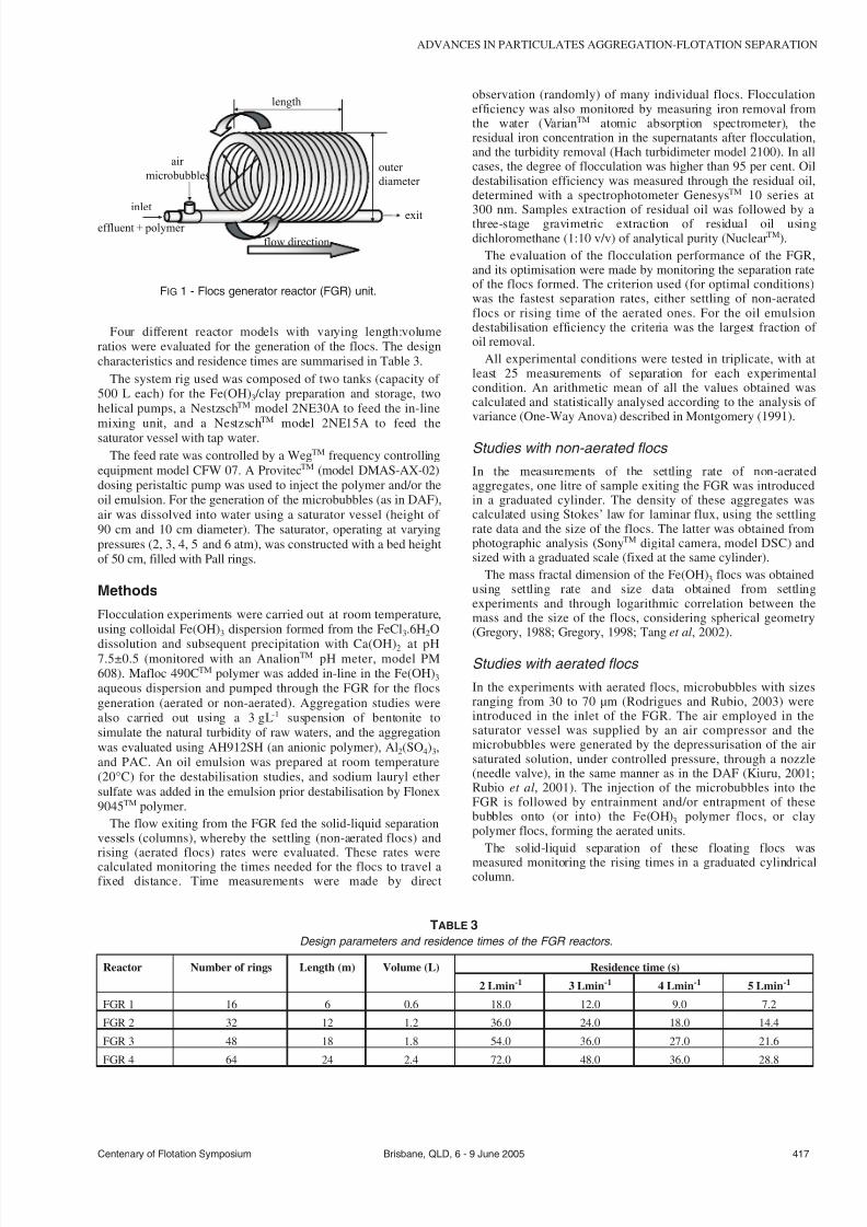
7232019 Advances in Particulates Aggregation-Flotation Separation
httpslidepdfcomreaderfulladvances-in-particulates-aggregation-flotation-separation 39
Four different reactor models with varying lengthvolumeratios were evaluated for the generation of the flocs The designcharacteristics and residence times are summarised in Table 3
The system rig used was composed of two tanks (capacity of 500 L each) for the Fe(OH)3 clay preparation and storage twohelical pumps a NestzschTM model 2NE30A to feed the in-line
mixing unit and a Nestzsch
TM
model 2NE15A to feed thesaturator vessel with tap waterThe feed rate was controlled by a WegTM frequency controlling
equipment model CFW 07 A ProvitecTM (model DMAS-AX-02)dosing peristaltic pump was used to inject the polymer andor theoil emulsion For the generation of the microbubbles (as in DAF)air was dissolved into water using a saturator vessel (height of 90 cm and 10 cm diameter) The saturator operating at varyingpressures (2 3 4 5 and 6 atm) was constructed with a bed heightof 50 cm filled with Pall rings
Methods
Flocculation experiments were carried out at room temperatureusing colloidal Fe(OH)3 dispersion formed from the FeCl36H2O
dissolution and subsequent precipitation with Ca(OH)2 at pH75plusmn05 (monitored with an AnalionTM pH meter model PM608) Mafloc 490CTM polymer was added in-line in the Fe(OH)3aqueous dispersion and pumped through the FGR for the flocsgeneration (aerated or non-aerated) Aggregation studies werealso carried out using a 3 gL-1 suspension of bentonite tosimulate the natural turbidity of raw waters and the aggregationwas evaluated using AH912SH (an anionic polymer) Al2(SO4)3and PAC An oil emulsion was prepared at room temperature(20degC) for the destabilisation studies and sodium lauryl ethersulfate was added in the emulsion prior destabilisation by Flonex9045TM polymer
The flow exiting from the FGR fed the solid-liquid separationvessels (columns) whereby the settling (non-aerated flocs) andrising (aerated flocs) rates were evaluated These rates werecalculated monitoring the times needed for the flocs to travel afixed distance Time measurements were made by direct
observation (randomly) of many individual flocs Flocculationefficiency was also monitored by measuring iron removal fromthe water (VarianTM atomic absorption spectrometer) theresidual iron concentration in the supernatants after flocculationand the turbidity removal (Hach turbidimeter model 2100) In allcases the degree of flocculation was higher than 95 per cent Oildestabilisation efficiency was measured through the residual oildetermined with a spectrophotometer GenesysTM 10 series at
300 nm Samples extraction of residual oil was followed by athree-stage gravimetric extraction of residual oil usingdichloromethane (110 vv) of analytical purity (NuclearTM)
The evaluation of the flocculation performance of the FGRand its optimisation were made by monitoring the separation rateof the flocs formed The criterion used (for optimal conditions)was the fastest separation rates either settling of non-aeratedflocs or rising time of the aerated ones For the oil emulsiondestabilisation efficiency the criteria was the largest fraction of oil removal
All experimental conditions were tested in triplicate with atleast 25 measurements of separation for each experimentalcondition An arithmetic mean of all the values obtained wascalculated and statistically analysed according to the analysis of variance (One-Way Anova) described in Montgomery (1991)
Studies with non-aerated flocs
In the measurements of the settling rate of non-aeratedaggregates one litre of sample exiting the FGR was introducedin a graduated cylinder The density of these aggregates wascalculated using Stokesrsquo law for laminar flux using the settlingrate data and the size of the flocs The latter was obtained fromphotographic analysis (SonyTM digital camera model DSC) andsized with a graduated scale (fixed at the same cylinder)
The mass fractal dimension of the Fe(OH)3 flocs was obtainedusing settling rate and size data obtained from settlingexperiments and through logarithmic correlation between themass and the size of the flocs considering spherical geometry(Gregory 1988 Gregory 1998 Tang et al 2002)
Studies with aerated flocs
In the experiments with aerated flocs microbubbles with sizesranging from 30 to 70 microm (Rodrigues and Rubio 2003) wereintroduced in the inlet of the FGR The air employed in thesaturator vessel was supplied by an air compressor and themicrobubbles were generated by the depressurisation of the airsaturated solution under controlled pressure through a nozzle(needle valve) in the same manner as in the DAF (Kiuru 2001Rubio et al 2001) The injection of the microbubbles into theFGR is followed by entrainment andor entrapment of thesebubbles onto (or into) the Fe(OH)3 polymer flocs or claypolymer flocs forming the aerated units
The solid-liquid separation of these floating flocs was
measured monitoring the rising times in a graduated cylindricalcolumn
Centenary of Flotation Symposium Brisbane QLD 6 - 9 June 2005 417
ADVANCES IN PARTICULATES AGGREGATION-FLOTATION SEPARATION
inlet
effluent + polymer
air
microbubbles
length
outer
diameter
exit
flow direction
FIG 1 - Flocs generator reactor (FGR) unit
Reactor Number of rings Length (m) Volume (L) Residence time (s)
2 Lmin-1 3 Lmin-1 4 Lmin-1 5 Lmin-1
FGR 1 16 6 06 180 120 90 72
FGR 2 32 12 12 360 240 180 144
FGR 3 48 18 18 540 360 270 216
FGR 4 64 24 24 720 480 360 288
TABLE 3Design parameters and residence times of the FGR reactors
7232019 Advances in Particulates Aggregation-Flotation Separation
httpslidepdfcomreaderfulladvances-in-particulates-aggregation-flotation-separation 49
Studies of the effect of the airsolids ratio on the separationefficiency were conducted fixing the ratio of injectedmicrobubbles at ten per cent and varying the saturation pressure(2 3 4 5 and 6 atmospheres) The calculation of the airsolidsratio was made using the following Equation 1
as Ri Av
FR solS =
[ ] (1)
where
as = airsolids ratio (mlmg-1)
Ri = rate of injection of microbubbles (Lmin-1)
Av = theoretical volume of dissolved air per litre of wateraccording to the Henry law (mlL-1)
FR = feed rate (Lmin-1)
S = saturator vessel efficiency (per cent)
Oil-in-water emulsion destabilisation
An 100 mgL-1 oil emulsion was prepared at room temperature
(20degC) for the destabilisation studies using a Turrax mixer at11 000 rpm during 15 minutes One mgL -1 of sodium lauryl ethersulfate was added to the emulsion prior to destabilisation withthe in-line injection of Flonex 9045TM polymer (5 10 20 30 40and 50 mgL-1) Oil destabilisation efficiency was measuredthrough the residual oil determined with a spectrophotometerStudies were carried out using the FGR 2 with a 3 Lmin -1 feedrate (residence time of 24 s)
RESULTS AND DISCUSSION
The formation of aggregates in the FGR and theirsettling rate
Fe(OH) 3 polymer flocs
The effect of the reactor type and the feed rate on the settling rateof the flocs generated is shown in Figure 2 Formation andgrowth of the Fe(OH)3 flocs is shown in Figure 3 (flow directionleft to right)
For all the reactors types the highest settling rates ranged from12 to 19 mh-1 showing an optimal for a feed rate of 4 Lmin-1 (orequivalent residence times as shown in Table 3) At the lowerfeed rates (2 Lmin-1) the low efficiency may be due to the lowturbulence in forming the flocs especially with high molecularweight polymeric flocculants such as the Mafloc 490CTM (Weirand Moody 2003) For the very high feed rates the systemturbulence contributed to the rupture of the flocs decreasing thesettling rate Following the results obtained the FGR 2 whichshowed the highest settling rates (19 mh-1) and yielded largeflocs (4 - 8 mm) was selected for further investigation
Clay aggregates
The aggregation of a clay suspension using an anionic polymeraluminium sulfate and PAC was evaluated in the FRG 2 (bestmodel) Figures 4 5 and 6 show clay aggregate settling ratesusing different concentrations of polymer Al2(SO4)3 and PACrespectively Figure 4 shows that low polymer dosages (025 and05 mgL-1) are efficient at producing good flocs and high settlingrates reaching as high as 17 mh-1 at 05 mgL-1 polymerconcentration Higher polymer dosages do not contribute tohigher settling rates following the usual polymer flocculationtrend at high concentrations
The settling rate of the clay particles is shown in Figure 5 fordifferent Al2(SO4)3 dosages at pH 65 (optimal coagulation pH)whereby Al(OH)3 is the main alum form present Results showthat the settling rate of the bentonite particles is higher for thehigher coagulant dosages in the FGR with settling rates of about6 mh-1 for 60 mgL-1 aluminium concentration
The settling rate of the clay particles using different PACconcentrations is shown in Figure 6 Results show that the lowerthe PAC dosages the higher the settling rates reaching values of
approximately 9 mh-1
for a 025 mgL-1
418 Brisbane QLD 6 - 9 June 2005 Centenary of Flotation Symposium
E CARIacuteSSIMI and J RUBIO
8
10
12
14
16
18
20
S e t t l i n g R a t e m h -
2 4 6
Feed Rate Lmin-1
FGR 1
FGR 2
FGR 3
FGR 4
FIG 2 - Fe(OH)3 flocs settling rate as a function of feed rate and
FGR model Conditions [Fe(OH)3] = 58 mgL-1
[Mafloc 490C] =
5 mgL-1
pH 75plusmn05
125 mm
FIG 3 - Fe(OH)3 flocs formation and growth through the FGR
(flow direction left to right)
2
4
6
8
10
12
14
16
18
S e t t l i n g R a t e m h - 1
025 05 1 2 4
[Anionic Polymer] mgL -1
FIG 4 - Clay flocs settling rate as a function of [AH912SH] polymer
concentration Conditions [Bentonite] = 03 gL-1
natural pH asymp 70
FGR 2 feed rate = 3 Lmin-1
Turbidity removal gt 96 per cent
7232019 Advances in Particulates Aggregation-Flotation Separation
httpslidepdfcomreaderfulladvances-in-particulates-aggregation-flotation-separation 59
Figure 7 shows the effect of the feed rate and residence timeon the flocs settling rates Results show that an increase in theinlet flow rate decreases the settling rate of the flocs generatedThis may be attributed to the high turbulence (determined by thesystem hydrodynamic conditions) which led to rupture of theformed flocs in the reactor Other authors (Akers et al 1987)have already investigated the effect of turbulent conditions intubular systems by observing the rupture of the flocs generatedusing small latex particles (097 microm) According to these authorsthe rupture of the flocs is highly dependent on the level of thedissipated turbulent energy Moreover the density distribution of the flocs or the conditions under which these flocs are formedmay interfere in their resistance to breakage
Figure 7 also shows the increase in the flocs settling rates withincrease in residence time The results show that for a residencetime up to 10 s the increase in settling rate is not as meaningfulas for times higher than 10 s This is probably due to fastpolymer adsorption onto the particles promoted by turbulence inthe FGR According to Weber (1972) polymer adsorption onto
particles is rapid and irreversible
Flocs characterisation
The results of physical characterisation of the Fe(OH)3 flocsgenerated in the FGR are shown in Figures 8 and 9 Figure 8shows that the flocs density decreases considerably as the flocssize increases due the flocs fractal dimension as previouslydescribed by others (Klimpel and Hogg 1991 Adachi andTanaka 1997 Gregory 1997 Tang 2002) The average density of the Fe(OH)3 flocs generated in the reactor was 1019plusmn18 kgm-3 forflocs with sizes ranging from 400 and 2000 microm
The mass fractal dimension (dF) of the Fe(OH)3 flocs obtainedin this work is shown in Figure 9 The value obtained of dF(298) characterises a dense floc with low porosity and aspherical format Values of about three have been alreadyreported in the literature and were explained as a result of lineartrajectories yielding more compact and spherical structures alsocalled lsquoballisticrsquo aggregation which happens mainly in theparticle-cluster case of aggregation (Gregory 1997 Burns et al1997 Burns et al 1998)
The FGR because of its coiled design presents somepeculiarities among others a fairly high shear rate foraggregation a secondary flow and centrifugal (collision) forcesThese promote good contact between the high molecular weightpolymer and the colloidal particles thus forming strong big
and compact structures According to Gregory (1981) the
Centenary of Flotation Symposium Brisbane QLD 6 - 9 June 2005 419
ADVANCES IN PARTICULATES AGGREGATION-FLOTATION SEPARATION
0
1
2
3
4
5
6
7
S e t t l i n g
R a t e m h - 1
10 20 30 40 50 60
[Al2(SO4)3] mgL-1
FIG 5 - Clay flocs settling rate as a function of the Al2(SO4)3concentration Conditions [Bentonite] = 03 gL
-1 pH asymp 65 FGR 2
feed rate = 3 Lmin-1
Turbidity removal gt 80 per cent
5
6
7
8
9
10
S e t t l i n g R a t e m h - 1
01 025 05 075 1
[PAC] mLL-1
FIG 6 - Clay flocs settling rate as a function of PAC concentration
Conditions [Bentonite] = 03 gL-1
natural pH asymp 70 FGR 2 feed
rate = 3 Lmin-1
Turbidity removal gt 98 per cent
0
2
4
6
8
10
12
4 7 10 13 16 19
Settling Rate mh-1
F e e d R a t e L m i n - 1
0
5
10
15
20
25
30
R e s i d e n c e T i m e s
Feed Rate
Residence Time
FIG 7 - Settling rate of the flocs as a function of the feed rate and
residence time Conditions [Fe(OH)3] = 58 mgL-1
[Mafloc 490C] =
5 mgL-1
FGR 2
1000
1010
1020
1030
1040
0 500 1000 1500 2000 2500
Flocs Size microm
F l o c s D e n s i t y
k g m - 3
FIG 8 - Density of the flocs as a function of Fe(OH)3 flocs size
Conditions [Fe(OH)3] = 58 mgL-1
FGR 2 pH 75plusmn05
7232019 Advances in Particulates Aggregation-Flotation Separation
httpslidepdfcomreaderfulladvances-in-particulates-aggregation-flotation-separation 69
secondary flow introduced by the coiled tubes may affectflocculation in several ways most notably there would be anincrease in the pressure drop across the tube for a given flow ratecausing an increased average shear rate inside the tube improvingthe flocculation Besides the significant advantages presented byin-line mixing (Cariacutessimi and Rubio 2005) it may be betterexplored by winding the tubes into a helical coil The resultsappear to be shorter and more compact tube lsquoflocculatorsrsquo
The formation of aerated flocs and their flotation
In this system not only is flocculation favoured (due to higherturbulence) but also entrainment andor entrapment(enmeshment) of air bubbles inside the flocs leading toformation of large aerated units This phenomenon was observedvisually and is represented schematically in Figure 10 Theaerated flocs lsquofloatrsquo and are easily separated as a flotationproduct (named here as floc-flotation) Therefore the FGR in
this case serves at the same time as a flocculator and as abubblefloc contactor
Fe(OH) 3 polymer flocs
The effect of the reactor type was again evaluated through thedetermination of the flocs rising rates using the techniquedescribed (results are shown in Figure 11)
In all reactors the highest rising rates were obtained at a feedrate of 2 Lmin-1 with rates ranging from 67 to 112 mh-1 For feedrates above 2 Lmin-1 there was a decrease in the rising rate due tothe increase in turbulence caused by the increase of the inlet flowrate and the injection of microbubbles However using FGR 2the difference in the rising rates of the flocs for the feed rates
investigated is not so meaningful
FGR 2 presented the best results in terms of floc rising rate
(112 mh-1) and this reactor was chosen for further tests FGR 1showed poor efficiency due the short length which did not allowa sufficient residence time for floc formation FGRs 3 and 4presented a decrease in the rising rates probably due to ruptureof the flocs at all feed rates As previously mentioned flocs donot continue to grow indefinitely during prolonged shear butattain an equilibrium size
The variation of the flocs rising velocity according to theairsolids ratio is shown in Figure 12
Figure 12 shows that best results are obtained with anairsolids ratio greater than 0025 mlmg-1 Previous studies of flotation of colloidal hydroxide iron flocs showed iron removalefficiencies greater than 80 per cent with an airsolids ratio of 05(Shannon and Buisson 1980) Results obtained in this work atlower airsolids ratio may be explained in terms of increasedefficiency of collision adhesion attachment and entrapment of the bubbles inside or onto the flocs which does not occur in theconventional process of DAF According to Purchas (1977) theairsolids ratio is more related to the amount of air precipitatedand not to the quantity of air bubbles actually adhering to thefloating particles Thus the results obtained validate thefunctioning of the FGR as a bubbleparticle contactor enablingthe use of airsolids ratios much lower than those utilised in
conventional processes
420 Brisbane QLD 6 - 9 June 2005 Centenary of Flotation Symposium
E CARIacuteSSIMI and J RUBIO
Polymer
Effluent
Exit
Aerated FlocsPolymer
Air Microbubbles
Solids
Air
FIG 10 - Generation and growing of aerated flocs inside the FGR
85
90
95
100
105
110
115
R i s e R a t e m h -
2 4 6
Feed Rate Lmin-1
FGR 1
FGR 2
FGR 3
FGR 4
FIG 11 - Rise rate of the flocs as a function of feed rate and FGR
type Conditions [Fe(OH)3] = 58 mgL-1
[Mafloc 490C] = 5 mgL-1
air injection ratio = 50 per cent saturation pressure = 4 atm pH
75plusmn05
dF = 29828
1
2
3
4
25 27 29 31 33 35
log (flocs size)
l o g
( f l o c s m a s s )
FIG 9 - Fractal dimension of Fe(OH)3 flocs Conditions [Fe(OH)3] =
58 mgL-1
[Mafloc 490C] = 5 mgL-1
FGR 2 pH 75plusmn05
25
50
75
100
5
001 0015 002 0025 003 0035 004
Airsolids Ratio mLmg-1
R i s e R a t e m
h - 1
FIG 12 - Rise rate of the flocs as a function of the airsolids ratio
Conditions [Mafloc 490C] = 5 mgL-1
FGR 2 pH 75plusmn05
7232019 Advances in Particulates Aggregation-Flotation Separation
httpslidepdfcomreaderfulladvances-in-particulates-aggregation-flotation-separation 79
Comparative results obtained in this work revealed that theaerated separation rates are of the order of six times higher thanthe flocs settling rates The floating rates of the aerated flocsreaching values greater than 100 mh-1 are the result of the airvolume inside the floc structure plus the volume given by theadhered bubbles at the flocwater interface Accordinglycalculations of the equivalent diameter of bubbles which wouldgive such a rising rate were made and compared to the rising
(floating) flocs formed in the FGR (Figure 13)
The diameter of the equivalent bubbles calculated from theStokes equation for the rise rates of 67 to 112 mh-1 yielded anair bubble size (diameter) between 185 to 240 microm Because themicrobubbles injected measured experimentally (Rodrigues andRubio 2003) between 30 and 70 microm the only explanation forthis phenomenon is the air volume in the flocs Moreover thesevalues when compared to conventional DAF are much highermeaning that using the FGR as bubbles-flocs contactor may lead
to a very high capacity flotation system Some authors (Da Rosa2001 Rubio et al 2001 Haarhoff and Edzwald 2001) explainthe high rise rate in terms of the probability of bubble formationand rapid occlusion (entrapment) within flocs nucleation of bubbles at flocwater interfaces polymer coiling as a result of lsquosalting outrsquo effects at the aqueousair interface and plug flowmixing
Clay aerated aggregates
The rising rates of the aerated clay flocs using different dosagesof an anionic polyacrylamide are shown in Figure 14 Theconcentration of 05 mgL-1 showed the best rise results reachingvalues in the order of 115 mh-1 Results showed that higherpolymer doses are not efficient to increase the rise rate of the
clay flocs Overdose of the reagent (up to 05 mgL -1) reversed thesuperficial charge of the particles and prejudiced its aggregationThe rising rates of the aerated clay aggregates for different
doses of Al2(SO4)3 are shown in Figure 15 The best rise velocity(88 mh-1) is shown for the highest coagulant dosage (60 mgL -1)At high coagulant doses a higher concentration of Al(OH)3precipitates will be formed (pH 65) and the enmeshment of clayparticles by the precipitates and by the microbubbles will favourturbidity reduction
The rising rates of the aerated clay aggregates for differentdoses of PAC are shown in Figure 16 Results show that forhigher PAC doses the rising rate of the aggregates decreases Thelower PAC dose (025 mlL-1) showed the best rising velocity(98 mh-1) The rising rate probably decreases for higher PACdosages due to the large quantity of precipitates that aregenerated at these high reagent doses
Oil-in-water emulsion destabilisation
Destabilisation of a diesel oil emulsion employing Flonex 9045TM
polymer is shown in Figure 17 Results show that even the lower
dosage of the polymer flocculant (5 mgL-1) is enough todestabilise the emulsion with oil removal efficiencies reaching 90per cent Residual oil concentrations were about 6 - 9 mgL-1
In this case the effect of flocculation on the destabilisation of the oil emulsion was through the high turbulence promoted bythe FGR with velocity gradients up to 1400 s-1 (for a 3 Lmin-1
feed rate) (Cariacutessimi and Rubio 2005) The sodium lauryl ethersulfate surfactant used prior to the cationic polyacrylamideaddition allowed better oil removal results with low polymerdosages (Palanuwech and Coupland 2003)
CONCLUSIONS
An innovative in-line flocculation lsquohelicalrsquo unit named flocsgenerator reactor (FGR) was developed for the generation of
polymeric (aerated and non-aerated) flocs and oil-in-water
Centenary of Flotation Symposium Brisbane QLD 6 - 9 June 2005 421
ADVANCES IN PARTICULATES AGGREGATION-FLOTATION SEPARATION
180
200
220
240
65 75 85 95 105 115
Rise Rate mh -1
E q u i v a l e n t D i a m e t e r
m micro
FIG 13 - Equivalent diameter of bubbles as a function of the rise
rate (values obtained with the aerated flocs)
60
70
80
90
100
110
120
R i s e R
a t e m h -
025 05 1 2 4 6 8
[Anionic Polymer] mgL-1
FIG 14 - Clay rise rate as a function of [AH912SH] polymer
concentration Conditions [Bentonite] = 03 gL-1
natural pH asymp 70
FGR 2 feed rate = 3 Lmin-1
air injection ratio = 50 per cent
saturation pressure = 4 atm turbidity removal gt 88 per cent
60
65
70
75
80
85
90
R i s e R a t e m h - 1
10 20 30 40 50 60
[Al2(SO4)3] mgL-1
FIG 15 - Clay rise rate as a function of Al2(SO4)3 concentration
Conditions [Bentonite] = 03 gL-1
pH asymp 65 FGR 2 feed rate =
3 Lmin-1
air injection ratio = 50 per cent saturation pressure =
4 atm turbidity removal gt93 per cent
7232019 Advances in Particulates Aggregation-Flotation Separation
httpslidepdfcomreaderfulladvances-in-particulates-aggregation-flotation-separation 89
destabilisation The studies showed high efficiency for thegeneration of Fe(OH)3 and clay flocs with the employment of high molecular weight polymers The polymer flocs obtainedwere well structured large and the Fe(OH)3 flocs presented afractal dimension of 298 characteristic of dense flocs with lowporosity and spherical format The FGR may also be used as afloc-bubble contactor to generate large aerated flocs (5 - 8 mm)
The FGR appears to have some advantages for the formation of polymer flocs namely suitable flow mixing absence of short-circuits or dead zones plug flow profile low arearequirement absence of moving parts simple design and lowmechanical and electrical energy needs Solid-liquid separationof the flocs by settling reached rates of about 18 - 24 mh-1
compared to more than 100 mh-1 rise rate for aerated flocs Thesevalues are higher than those found in conventional sedimentationor DAF units The FGR appears to have good potential as alsquoflocculatorrsquo (or flotation)-separator device in applicationsrequiring high rate solid-liquid separations Successful examplesof emulsified oil and solids removal from water were shown andbecause in all cases efficiencies were high (gt90 per centremoval) it is believed that this kind of flocculation-flotationappears to have a great potential in solid-liquid or liquid-liquid
separation
ACKNOWLEDGEMENTS
The authors thank all the colleagues at Laboratoacuterio deTecnologia Mineral e Ambiental (LTM) at UFRGS for theirassistance and friendly atmosphere and to all institutionssupporting research in Brazil especially CNPq (Institute of Millennium Project)
REFERENCESAdachi Y and Tanaka Y 1997 Settling velocity of an aluminium-kaolinit
floc Water Science and Technology 31(3)449-454Bio 2002 Flotaccedilatildeo ganha adeptos no Brasil Revista Brasileira de
Saneamento e Meio Ambiente JulySeptember pp 40-47 (inPortuguese)
Burns J L Yan Y D Jameson G J and Biggs S A 1997 A lightscattering study of the fractal aggregation behavior of a modelcolloidal system Langmuir 136413-6420
Burns J L Yan Y D Jameson G J and Biggs S A 1998 A comparisonof the fractal properties of salt-aggregated and polymer-flocculatedcolloidal particles Progress in Colloid and Polymer Science11070-75
Cariacutessimi E and Rubio J 2005 The flocs generator reactor ndash FGR anew basis for flocculation and solid-liquid separation International Journal of Mineral Processing 75(3-4)237-247
Costa C A and Rubio J 2005 Deinking flotation influence of calciumsoap and surface-active substances Minerals Engineering18(1)59-64
Crockett J and Muntisov M 1995 Potable water treatment by dissolvedair flotationfiltration in Proceedings Modern Techniques in Water and Wastewater Treatment (eds L O Kolarik and A J Priestley) pp15-18
Da Rosa J J 2001 Tratamento de efluentes oleosos por floculaccedilatildeopneumaacutetica em linha e separaccedilatildeo por flotaccedilatildeo Processo FF ThesisUFRGSPPGEM Jorge Rubio 126 p (in Portuguese)
Edzwald J K 1995 Principles and applications of dissolved air flotationWater Science and Technology 31(3-4)1-23
Feacuteris L A Gallina C W Rodrigues R T and Rubio J 2001 Optimizingdissolved air flotation design and saturation Water Science and Technology 43(8)153-157
Filho A C T P and Brandno C C S 2001 Evaluation of flocculation anddissolved air flotation as an advanced wastewater treatment Water Science and Technology 43(8)91-98
Finch J A 1995 Column flotation a selected review-part IV flotationdevices Minerals Engineering 8(6)587-602
Finch J A and Hardie C A 1999 An example of innovation from thewaste management industry deinking flotation cells Minerals Engineering 12(5)467-475
Gregory J 1981 Flocculation in laminar tube flow Chemical Engineering Science 36(11)1789-1794
Gregory J 1988 Polymer adsorption and flocculation in shearedsuspensions Colloids and Surfaces 31231-253
Gregory J 1997 The density of particle aggregates Water Science and Technology 36(4)1-13
Gregory J 1998 The role of floc density in solid-liquid separationFiltration and Separation 35(4)367-371
Haarhoff J and Edzwald J K 2001 Modelling of floc-bubble aggregaterise rates in dissolved air flotation Water Science and Technology43(8)175-184
Harbort G J Jackson B R and Manlapig E V 1994 Recent advances inJameson flotation cell technology Minerals Engineering7(2-3)319-332
Kempeneers S Menxel F V and Gille L 2001 A decade of largeexperience in dissolved air flotation Water Science and Technology43(8)35-41
Kiuru H J 2001 Development of dissolved air flotation technology fromthe first generation to the newest (third) one (DAF in turbulent flowconditions) Water Science and Technology 43(8)1-7
Klimpel R C and Hogg R 1991 Evaluation of floc structures Colloidsand Surfaces 55279-288
Liers S Baeyens J and Mochtar I 1996 Modelling dissolved airflotation Water Environment Research 68(6)1061-1075
422 Brisbane QLD 6 - 9 June 2005 Centenary of Flotation Symposium
E CARIacuteSSIMI and J RUBIO
0
20
40
60
80
100
0 20 40 60
[Cationic Polymer] mgL-1
O i l r e m o v a l
0
20
40
60
80
100
O i l R e s i d u a l m g L - 1
Oil Removal
Oil Residual
FIG 17 - Diesel oil emulsion flocculation (destabilisation) with
Flonex 9045 polymer Conditions [ow emulsion] = 100 mgL-1
[sodium lauryl ether sulfate] = 1 mgL-1
temperature = 20degC FGR
2 feed rate = 3 Lmin-1
80
85
90
95
100
R i s e R a t e m h - 1
01 025 05 075 1
[PAC] mLL-1
FIG 16 - Clay rise rates as a function of the PAC concentration
Conditions [Bentonite] = 03 gL-1
natural pH asymp 70 FGR 2 feed
rate = 3 Lmin-1
air injection ratio = 50 per cent saturation
pressure = 4 atm turbidity removal gt98 per cent
7232019 Advances in Particulates Aggregation-Flotation Separation
httpslidepdfcomreaderfulladvances-in-particulates-aggregation-flotation-separation 99
Matis K A and Lazaridis N K 2002 Flotation techniques in watertechnology for metals recovery dispersed-air versus dissolved-airflotation J Min Metall A381-27
Matis K A 1995 Flotation Science and Engineering 584 p (MarcelDekker New York)
Matis K A Zouboulis A I Gallios G P Erwe T and Bloumlcher C 2004Application of flotation for the separation of metal-loaded zeolitesChemosphere 5565-72
Mavros P and Matis K A (eds) 1992 Innovations in Flotation
Technology (Kluwer Academic Publishers Dordrecht)Montgomery D C 1991 Design and Analysis of Experiments third
edition 649 p (John Wiley and Sons Inc Canada)Oslashdegaard H 2001 The use of dissolved air flotation in municipal
wastewater treatment Water Science and Technology 43(8)83-90Oliveira J C 2004 Tecnologia para despoluir o rio Pinheiros
Saneamento Ambiental 10868 (in Portuguese)Owen J J Morse D E Morse W O and Jovine R 1999 New
developments in flotation equipment for water treatment systems in Advances in Flotation Technology (eds B K Parekh and J D Miller)pp 381-389 (Society for Mining Metallurgy and Exploration Inc(SME) Littleton)
Palanuweck J and Coupland J N 2003 Effect of surfactant type on thestability of oil-in-water emulsions to dispersed phase crystallizationColloids and Surfaces A Physicochemical and Engineering Aspects223251-262
Parekh B K and Miller J D (eds) 1999 Advances in FlotationTechnology (Society for Mining Metallurgy and Exploration Inc(SME) Littleton)
Purchas D B 1977 SolidLiquid Separation Equipment Scale Up 584 p(Upland Press Ltd)
Reali M A P and Marchetto M 2001 High-rate dissolved air flotationfor water treatment Water Science and Technology 43(8)51-57
Rodrigues R T and Rubio J 2003 New basis for measuring the sizedistribution of bubbles Minerals Engineering 16757-765
Rosa J J and Rubio J 2005 The FF (flocculation-flotation) process Minerals Engineering 18(7)701-707
Rubio J 1998 Environmental applications of the flotation process in Effluent Treatment in the Mining Industry (eds S H Castro F Vergaraand M Sanchez) Chapter 8 pp 335-364 (University of Concepcioacuten-Chile Chile)
Rubio J 2003 Unconventional flocculation and flotation in ProceedingsFlotation and Flocculation From Fundamentals to ApplicationsStrategic Conference and Workshop Hawaii (eds J Ralston J Miller
and J Rubio) pp 17-32Rubio J Souza M L and Smith R W 2002 Overview of flotation as a
wastewater treatment technique Minerals Engineering 15139-155Rubio J Tessele F Porcile P A and Marinkovic E 2001 Flotacioacuten
como proceso de remocioacuten de contaminantes I Principios baacutesicosteacutecnicas y aplicaciones Minerales 56(242)9-18 (in Spanish)
Schofield T 2001 Dissolved air flotation in drinking water productionWater Science and Technology 43(8)9-18
Shannon W T and Buisson D H 1980 Dissolved air flotation in hotwater Water Research 14(7)759-765
Tang P Greenwood J and Raper A 2002 A model to describe thesettling behavior or fractal aggregates Journal of Colloid and Interface Science 247210-219
Voronin N N and Dibrov I A 1998 Classification of flotation processesin wastewater decontamination Journal of Environmental Engineering 124(5)469-472
Weber W J 1972 Physicochemical Processes for Water Quality Control640 p (Wiley-Interscience New York-USA)
Weir S and Moody G M 2003 The importance of flocculant choice withconsideration to mixing energy to achieve efficient solidliquidseparation Minerals Engineering 16(2)109-113
Zhou Z A Zhenghe Xu and Finch J A 1994 On the role of cavitationin particle collection during flotation ndash a critical review Minerals Engineering 7(9)1073-1084
Centenary of Flotation Symposium Brisbane QLD 6 - 9 June 2005 423
ADVANCES IN PARTICULATES AGGREGATION-FLOTATION SEPARATION
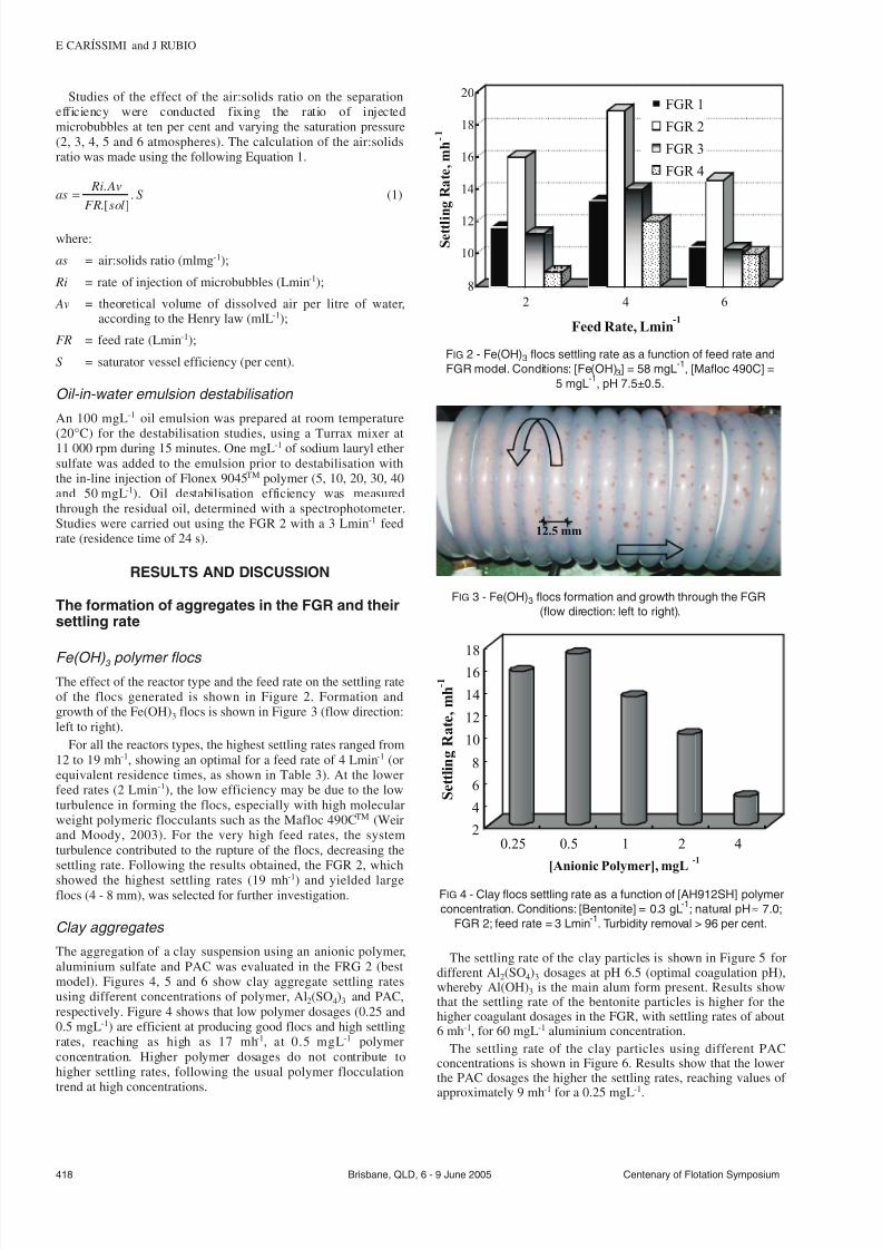
7232019 Advances in Particulates Aggregation-Flotation Separation
httpslidepdfcomreaderfulladvances-in-particulates-aggregation-flotation-separation 49
Studies of the effect of the airsolids ratio on the separationefficiency were conducted fixing the ratio of injectedmicrobubbles at ten per cent and varying the saturation pressure(2 3 4 5 and 6 atmospheres) The calculation of the airsolidsratio was made using the following Equation 1
as Ri Av
FR solS =
[ ] (1)
where
as = airsolids ratio (mlmg-1)
Ri = rate of injection of microbubbles (Lmin-1)
Av = theoretical volume of dissolved air per litre of wateraccording to the Henry law (mlL-1)
FR = feed rate (Lmin-1)
S = saturator vessel efficiency (per cent)
Oil-in-water emulsion destabilisation
An 100 mgL-1 oil emulsion was prepared at room temperature
(20degC) for the destabilisation studies using a Turrax mixer at11 000 rpm during 15 minutes One mgL -1 of sodium lauryl ethersulfate was added to the emulsion prior to destabilisation withthe in-line injection of Flonex 9045TM polymer (5 10 20 30 40and 50 mgL-1) Oil destabilisation efficiency was measuredthrough the residual oil determined with a spectrophotometerStudies were carried out using the FGR 2 with a 3 Lmin -1 feedrate (residence time of 24 s)
RESULTS AND DISCUSSION
The formation of aggregates in the FGR and theirsettling rate
Fe(OH) 3 polymer flocs
The effect of the reactor type and the feed rate on the settling rateof the flocs generated is shown in Figure 2 Formation andgrowth of the Fe(OH)3 flocs is shown in Figure 3 (flow directionleft to right)
For all the reactors types the highest settling rates ranged from12 to 19 mh-1 showing an optimal for a feed rate of 4 Lmin-1 (orequivalent residence times as shown in Table 3) At the lowerfeed rates (2 Lmin-1) the low efficiency may be due to the lowturbulence in forming the flocs especially with high molecularweight polymeric flocculants such as the Mafloc 490CTM (Weirand Moody 2003) For the very high feed rates the systemturbulence contributed to the rupture of the flocs decreasing thesettling rate Following the results obtained the FGR 2 whichshowed the highest settling rates (19 mh-1) and yielded largeflocs (4 - 8 mm) was selected for further investigation
Clay aggregates
The aggregation of a clay suspension using an anionic polymeraluminium sulfate and PAC was evaluated in the FRG 2 (bestmodel) Figures 4 5 and 6 show clay aggregate settling ratesusing different concentrations of polymer Al2(SO4)3 and PACrespectively Figure 4 shows that low polymer dosages (025 and05 mgL-1) are efficient at producing good flocs and high settlingrates reaching as high as 17 mh-1 at 05 mgL-1 polymerconcentration Higher polymer dosages do not contribute tohigher settling rates following the usual polymer flocculationtrend at high concentrations
The settling rate of the clay particles is shown in Figure 5 fordifferent Al2(SO4)3 dosages at pH 65 (optimal coagulation pH)whereby Al(OH)3 is the main alum form present Results showthat the settling rate of the bentonite particles is higher for thehigher coagulant dosages in the FGR with settling rates of about6 mh-1 for 60 mgL-1 aluminium concentration
The settling rate of the clay particles using different PACconcentrations is shown in Figure 6 Results show that the lowerthe PAC dosages the higher the settling rates reaching values of
approximately 9 mh-1
for a 025 mgL-1
418 Brisbane QLD 6 - 9 June 2005 Centenary of Flotation Symposium
E CARIacuteSSIMI and J RUBIO
8
10
12
14
16
18
20
S e t t l i n g R a t e m h -
2 4 6
Feed Rate Lmin-1
FGR 1
FGR 2
FGR 3
FGR 4
FIG 2 - Fe(OH)3 flocs settling rate as a function of feed rate and
FGR model Conditions [Fe(OH)3] = 58 mgL-1
[Mafloc 490C] =
5 mgL-1
pH 75plusmn05
125 mm
FIG 3 - Fe(OH)3 flocs formation and growth through the FGR
(flow direction left to right)
2
4
6
8
10
12
14
16
18
S e t t l i n g R a t e m h - 1
025 05 1 2 4
[Anionic Polymer] mgL -1
FIG 4 - Clay flocs settling rate as a function of [AH912SH] polymer
concentration Conditions [Bentonite] = 03 gL-1
natural pH asymp 70
FGR 2 feed rate = 3 Lmin-1
Turbidity removal gt 96 per cent
7232019 Advances in Particulates Aggregation-Flotation Separation
httpslidepdfcomreaderfulladvances-in-particulates-aggregation-flotation-separation 59
Figure 7 shows the effect of the feed rate and residence timeon the flocs settling rates Results show that an increase in theinlet flow rate decreases the settling rate of the flocs generatedThis may be attributed to the high turbulence (determined by thesystem hydrodynamic conditions) which led to rupture of theformed flocs in the reactor Other authors (Akers et al 1987)have already investigated the effect of turbulent conditions intubular systems by observing the rupture of the flocs generatedusing small latex particles (097 microm) According to these authorsthe rupture of the flocs is highly dependent on the level of thedissipated turbulent energy Moreover the density distribution of the flocs or the conditions under which these flocs are formedmay interfere in their resistance to breakage
Figure 7 also shows the increase in the flocs settling rates withincrease in residence time The results show that for a residencetime up to 10 s the increase in settling rate is not as meaningfulas for times higher than 10 s This is probably due to fastpolymer adsorption onto the particles promoted by turbulence inthe FGR According to Weber (1972) polymer adsorption onto
particles is rapid and irreversible
Flocs characterisation
The results of physical characterisation of the Fe(OH)3 flocsgenerated in the FGR are shown in Figures 8 and 9 Figure 8shows that the flocs density decreases considerably as the flocssize increases due the flocs fractal dimension as previouslydescribed by others (Klimpel and Hogg 1991 Adachi andTanaka 1997 Gregory 1997 Tang 2002) The average density of the Fe(OH)3 flocs generated in the reactor was 1019plusmn18 kgm-3 forflocs with sizes ranging from 400 and 2000 microm
The mass fractal dimension (dF) of the Fe(OH)3 flocs obtainedin this work is shown in Figure 9 The value obtained of dF(298) characterises a dense floc with low porosity and aspherical format Values of about three have been alreadyreported in the literature and were explained as a result of lineartrajectories yielding more compact and spherical structures alsocalled lsquoballisticrsquo aggregation which happens mainly in theparticle-cluster case of aggregation (Gregory 1997 Burns et al1997 Burns et al 1998)
The FGR because of its coiled design presents somepeculiarities among others a fairly high shear rate foraggregation a secondary flow and centrifugal (collision) forcesThese promote good contact between the high molecular weightpolymer and the colloidal particles thus forming strong big
and compact structures According to Gregory (1981) the
Centenary of Flotation Symposium Brisbane QLD 6 - 9 June 2005 419
ADVANCES IN PARTICULATES AGGREGATION-FLOTATION SEPARATION
0
1
2
3
4
5
6
7
S e t t l i n g
R a t e m h - 1
10 20 30 40 50 60
[Al2(SO4)3] mgL-1
FIG 5 - Clay flocs settling rate as a function of the Al2(SO4)3concentration Conditions [Bentonite] = 03 gL
-1 pH asymp 65 FGR 2
feed rate = 3 Lmin-1
Turbidity removal gt 80 per cent
5
6
7
8
9
10
S e t t l i n g R a t e m h - 1
01 025 05 075 1
[PAC] mLL-1
FIG 6 - Clay flocs settling rate as a function of PAC concentration
Conditions [Bentonite] = 03 gL-1
natural pH asymp 70 FGR 2 feed
rate = 3 Lmin-1
Turbidity removal gt 98 per cent
0
2
4
6
8
10
12
4 7 10 13 16 19
Settling Rate mh-1
F e e d R a t e L m i n - 1
0
5
10
15
20
25
30
R e s i d e n c e T i m e s
Feed Rate
Residence Time
FIG 7 - Settling rate of the flocs as a function of the feed rate and
residence time Conditions [Fe(OH)3] = 58 mgL-1
[Mafloc 490C] =
5 mgL-1
FGR 2
1000
1010
1020
1030
1040
0 500 1000 1500 2000 2500
Flocs Size microm
F l o c s D e n s i t y
k g m - 3
FIG 8 - Density of the flocs as a function of Fe(OH)3 flocs size
Conditions [Fe(OH)3] = 58 mgL-1
FGR 2 pH 75plusmn05
7232019 Advances in Particulates Aggregation-Flotation Separation
httpslidepdfcomreaderfulladvances-in-particulates-aggregation-flotation-separation 69
secondary flow introduced by the coiled tubes may affectflocculation in several ways most notably there would be anincrease in the pressure drop across the tube for a given flow ratecausing an increased average shear rate inside the tube improvingthe flocculation Besides the significant advantages presented byin-line mixing (Cariacutessimi and Rubio 2005) it may be betterexplored by winding the tubes into a helical coil The resultsappear to be shorter and more compact tube lsquoflocculatorsrsquo
The formation of aerated flocs and their flotation
In this system not only is flocculation favoured (due to higherturbulence) but also entrainment andor entrapment(enmeshment) of air bubbles inside the flocs leading toformation of large aerated units This phenomenon was observedvisually and is represented schematically in Figure 10 Theaerated flocs lsquofloatrsquo and are easily separated as a flotationproduct (named here as floc-flotation) Therefore the FGR in
this case serves at the same time as a flocculator and as abubblefloc contactor
Fe(OH) 3 polymer flocs
The effect of the reactor type was again evaluated through thedetermination of the flocs rising rates using the techniquedescribed (results are shown in Figure 11)
In all reactors the highest rising rates were obtained at a feedrate of 2 Lmin-1 with rates ranging from 67 to 112 mh-1 For feedrates above 2 Lmin-1 there was a decrease in the rising rate due tothe increase in turbulence caused by the increase of the inlet flowrate and the injection of microbubbles However using FGR 2the difference in the rising rates of the flocs for the feed rates
investigated is not so meaningful
FGR 2 presented the best results in terms of floc rising rate
(112 mh-1) and this reactor was chosen for further tests FGR 1showed poor efficiency due the short length which did not allowa sufficient residence time for floc formation FGRs 3 and 4presented a decrease in the rising rates probably due to ruptureof the flocs at all feed rates As previously mentioned flocs donot continue to grow indefinitely during prolonged shear butattain an equilibrium size
The variation of the flocs rising velocity according to theairsolids ratio is shown in Figure 12
Figure 12 shows that best results are obtained with anairsolids ratio greater than 0025 mlmg-1 Previous studies of flotation of colloidal hydroxide iron flocs showed iron removalefficiencies greater than 80 per cent with an airsolids ratio of 05(Shannon and Buisson 1980) Results obtained in this work atlower airsolids ratio may be explained in terms of increasedefficiency of collision adhesion attachment and entrapment of the bubbles inside or onto the flocs which does not occur in theconventional process of DAF According to Purchas (1977) theairsolids ratio is more related to the amount of air precipitatedand not to the quantity of air bubbles actually adhering to thefloating particles Thus the results obtained validate thefunctioning of the FGR as a bubbleparticle contactor enablingthe use of airsolids ratios much lower than those utilised in
conventional processes
420 Brisbane QLD 6 - 9 June 2005 Centenary of Flotation Symposium
E CARIacuteSSIMI and J RUBIO
Polymer
Effluent
Exit
Aerated FlocsPolymer
Air Microbubbles
Solids
Air
FIG 10 - Generation and growing of aerated flocs inside the FGR
85
90
95
100
105
110
115
R i s e R a t e m h -
2 4 6
Feed Rate Lmin-1
FGR 1
FGR 2
FGR 3
FGR 4
FIG 11 - Rise rate of the flocs as a function of feed rate and FGR
type Conditions [Fe(OH)3] = 58 mgL-1
[Mafloc 490C] = 5 mgL-1
air injection ratio = 50 per cent saturation pressure = 4 atm pH
75plusmn05
dF = 29828
1
2
3
4
25 27 29 31 33 35
log (flocs size)
l o g
( f l o c s m a s s )
FIG 9 - Fractal dimension of Fe(OH)3 flocs Conditions [Fe(OH)3] =
58 mgL-1
[Mafloc 490C] = 5 mgL-1
FGR 2 pH 75plusmn05
25
50
75
100
5
001 0015 002 0025 003 0035 004
Airsolids Ratio mLmg-1
R i s e R a t e m
h - 1
FIG 12 - Rise rate of the flocs as a function of the airsolids ratio
Conditions [Mafloc 490C] = 5 mgL-1
FGR 2 pH 75plusmn05
7232019 Advances in Particulates Aggregation-Flotation Separation
httpslidepdfcomreaderfulladvances-in-particulates-aggregation-flotation-separation 79
Comparative results obtained in this work revealed that theaerated separation rates are of the order of six times higher thanthe flocs settling rates The floating rates of the aerated flocsreaching values greater than 100 mh-1 are the result of the airvolume inside the floc structure plus the volume given by theadhered bubbles at the flocwater interface Accordinglycalculations of the equivalent diameter of bubbles which wouldgive such a rising rate were made and compared to the rising
(floating) flocs formed in the FGR (Figure 13)
The diameter of the equivalent bubbles calculated from theStokes equation for the rise rates of 67 to 112 mh-1 yielded anair bubble size (diameter) between 185 to 240 microm Because themicrobubbles injected measured experimentally (Rodrigues andRubio 2003) between 30 and 70 microm the only explanation forthis phenomenon is the air volume in the flocs Moreover thesevalues when compared to conventional DAF are much highermeaning that using the FGR as bubbles-flocs contactor may lead
to a very high capacity flotation system Some authors (Da Rosa2001 Rubio et al 2001 Haarhoff and Edzwald 2001) explainthe high rise rate in terms of the probability of bubble formationand rapid occlusion (entrapment) within flocs nucleation of bubbles at flocwater interfaces polymer coiling as a result of lsquosalting outrsquo effects at the aqueousair interface and plug flowmixing
Clay aerated aggregates
The rising rates of the aerated clay flocs using different dosagesof an anionic polyacrylamide are shown in Figure 14 Theconcentration of 05 mgL-1 showed the best rise results reachingvalues in the order of 115 mh-1 Results showed that higherpolymer doses are not efficient to increase the rise rate of the
clay flocs Overdose of the reagent (up to 05 mgL -1) reversed thesuperficial charge of the particles and prejudiced its aggregationThe rising rates of the aerated clay aggregates for different
doses of Al2(SO4)3 are shown in Figure 15 The best rise velocity(88 mh-1) is shown for the highest coagulant dosage (60 mgL -1)At high coagulant doses a higher concentration of Al(OH)3precipitates will be formed (pH 65) and the enmeshment of clayparticles by the precipitates and by the microbubbles will favourturbidity reduction
The rising rates of the aerated clay aggregates for differentdoses of PAC are shown in Figure 16 Results show that forhigher PAC doses the rising rate of the aggregates decreases Thelower PAC dose (025 mlL-1) showed the best rising velocity(98 mh-1) The rising rate probably decreases for higher PACdosages due to the large quantity of precipitates that aregenerated at these high reagent doses
Oil-in-water emulsion destabilisation
Destabilisation of a diesel oil emulsion employing Flonex 9045TM
polymer is shown in Figure 17 Results show that even the lower
dosage of the polymer flocculant (5 mgL-1) is enough todestabilise the emulsion with oil removal efficiencies reaching 90per cent Residual oil concentrations were about 6 - 9 mgL-1
In this case the effect of flocculation on the destabilisation of the oil emulsion was through the high turbulence promoted bythe FGR with velocity gradients up to 1400 s-1 (for a 3 Lmin-1
feed rate) (Cariacutessimi and Rubio 2005) The sodium lauryl ethersulfate surfactant used prior to the cationic polyacrylamideaddition allowed better oil removal results with low polymerdosages (Palanuwech and Coupland 2003)
CONCLUSIONS
An innovative in-line flocculation lsquohelicalrsquo unit named flocsgenerator reactor (FGR) was developed for the generation of
polymeric (aerated and non-aerated) flocs and oil-in-water
Centenary of Flotation Symposium Brisbane QLD 6 - 9 June 2005 421
ADVANCES IN PARTICULATES AGGREGATION-FLOTATION SEPARATION
180
200
220
240
65 75 85 95 105 115
Rise Rate mh -1
E q u i v a l e n t D i a m e t e r
m micro
FIG 13 - Equivalent diameter of bubbles as a function of the rise
rate (values obtained with the aerated flocs)
60
70
80
90
100
110
120
R i s e R
a t e m h -
025 05 1 2 4 6 8
[Anionic Polymer] mgL-1
FIG 14 - Clay rise rate as a function of [AH912SH] polymer
concentration Conditions [Bentonite] = 03 gL-1
natural pH asymp 70
FGR 2 feed rate = 3 Lmin-1
air injection ratio = 50 per cent
saturation pressure = 4 atm turbidity removal gt 88 per cent
60
65
70
75
80
85
90
R i s e R a t e m h - 1
10 20 30 40 50 60
[Al2(SO4)3] mgL-1
FIG 15 - Clay rise rate as a function of Al2(SO4)3 concentration
Conditions [Bentonite] = 03 gL-1
pH asymp 65 FGR 2 feed rate =
3 Lmin-1
air injection ratio = 50 per cent saturation pressure =
4 atm turbidity removal gt93 per cent
7232019 Advances in Particulates Aggregation-Flotation Separation
httpslidepdfcomreaderfulladvances-in-particulates-aggregation-flotation-separation 89
destabilisation The studies showed high efficiency for thegeneration of Fe(OH)3 and clay flocs with the employment of high molecular weight polymers The polymer flocs obtainedwere well structured large and the Fe(OH)3 flocs presented afractal dimension of 298 characteristic of dense flocs with lowporosity and spherical format The FGR may also be used as afloc-bubble contactor to generate large aerated flocs (5 - 8 mm)
The FGR appears to have some advantages for the formation of polymer flocs namely suitable flow mixing absence of short-circuits or dead zones plug flow profile low arearequirement absence of moving parts simple design and lowmechanical and electrical energy needs Solid-liquid separationof the flocs by settling reached rates of about 18 - 24 mh-1
compared to more than 100 mh-1 rise rate for aerated flocs Thesevalues are higher than those found in conventional sedimentationor DAF units The FGR appears to have good potential as alsquoflocculatorrsquo (or flotation)-separator device in applicationsrequiring high rate solid-liquid separations Successful examplesof emulsified oil and solids removal from water were shown andbecause in all cases efficiencies were high (gt90 per centremoval) it is believed that this kind of flocculation-flotationappears to have a great potential in solid-liquid or liquid-liquid
separation
ACKNOWLEDGEMENTS
The authors thank all the colleagues at Laboratoacuterio deTecnologia Mineral e Ambiental (LTM) at UFRGS for theirassistance and friendly atmosphere and to all institutionssupporting research in Brazil especially CNPq (Institute of Millennium Project)
REFERENCESAdachi Y and Tanaka Y 1997 Settling velocity of an aluminium-kaolinit
floc Water Science and Technology 31(3)449-454Bio 2002 Flotaccedilatildeo ganha adeptos no Brasil Revista Brasileira de
Saneamento e Meio Ambiente JulySeptember pp 40-47 (inPortuguese)
Burns J L Yan Y D Jameson G J and Biggs S A 1997 A lightscattering study of the fractal aggregation behavior of a modelcolloidal system Langmuir 136413-6420
Burns J L Yan Y D Jameson G J and Biggs S A 1998 A comparisonof the fractal properties of salt-aggregated and polymer-flocculatedcolloidal particles Progress in Colloid and Polymer Science11070-75
Cariacutessimi E and Rubio J 2005 The flocs generator reactor ndash FGR anew basis for flocculation and solid-liquid separation International Journal of Mineral Processing 75(3-4)237-247
Costa C A and Rubio J 2005 Deinking flotation influence of calciumsoap and surface-active substances Minerals Engineering18(1)59-64
Crockett J and Muntisov M 1995 Potable water treatment by dissolvedair flotationfiltration in Proceedings Modern Techniques in Water and Wastewater Treatment (eds L O Kolarik and A J Priestley) pp15-18
Da Rosa J J 2001 Tratamento de efluentes oleosos por floculaccedilatildeopneumaacutetica em linha e separaccedilatildeo por flotaccedilatildeo Processo FF ThesisUFRGSPPGEM Jorge Rubio 126 p (in Portuguese)
Edzwald J K 1995 Principles and applications of dissolved air flotationWater Science and Technology 31(3-4)1-23
Feacuteris L A Gallina C W Rodrigues R T and Rubio J 2001 Optimizingdissolved air flotation design and saturation Water Science and Technology 43(8)153-157
Filho A C T P and Brandno C C S 2001 Evaluation of flocculation anddissolved air flotation as an advanced wastewater treatment Water Science and Technology 43(8)91-98
Finch J A 1995 Column flotation a selected review-part IV flotationdevices Minerals Engineering 8(6)587-602
Finch J A and Hardie C A 1999 An example of innovation from thewaste management industry deinking flotation cells Minerals Engineering 12(5)467-475
Gregory J 1981 Flocculation in laminar tube flow Chemical Engineering Science 36(11)1789-1794
Gregory J 1988 Polymer adsorption and flocculation in shearedsuspensions Colloids and Surfaces 31231-253
Gregory J 1997 The density of particle aggregates Water Science and Technology 36(4)1-13
Gregory J 1998 The role of floc density in solid-liquid separationFiltration and Separation 35(4)367-371
Haarhoff J and Edzwald J K 2001 Modelling of floc-bubble aggregaterise rates in dissolved air flotation Water Science and Technology43(8)175-184
Harbort G J Jackson B R and Manlapig E V 1994 Recent advances inJameson flotation cell technology Minerals Engineering7(2-3)319-332
Kempeneers S Menxel F V and Gille L 2001 A decade of largeexperience in dissolved air flotation Water Science and Technology43(8)35-41
Kiuru H J 2001 Development of dissolved air flotation technology fromthe first generation to the newest (third) one (DAF in turbulent flowconditions) Water Science and Technology 43(8)1-7
Klimpel R C and Hogg R 1991 Evaluation of floc structures Colloidsand Surfaces 55279-288
Liers S Baeyens J and Mochtar I 1996 Modelling dissolved airflotation Water Environment Research 68(6)1061-1075
422 Brisbane QLD 6 - 9 June 2005 Centenary of Flotation Symposium
E CARIacuteSSIMI and J RUBIO
0
20
40
60
80
100
0 20 40 60
[Cationic Polymer] mgL-1
O i l r e m o v a l
0
20
40
60
80
100
O i l R e s i d u a l m g L - 1
Oil Removal
Oil Residual
FIG 17 - Diesel oil emulsion flocculation (destabilisation) with
Flonex 9045 polymer Conditions [ow emulsion] = 100 mgL-1
[sodium lauryl ether sulfate] = 1 mgL-1
temperature = 20degC FGR
2 feed rate = 3 Lmin-1
80
85
90
95
100
R i s e R a t e m h - 1
01 025 05 075 1
[PAC] mLL-1
FIG 16 - Clay rise rates as a function of the PAC concentration
Conditions [Bentonite] = 03 gL-1
natural pH asymp 70 FGR 2 feed
rate = 3 Lmin-1
air injection ratio = 50 per cent saturation
pressure = 4 atm turbidity removal gt98 per cent
7232019 Advances in Particulates Aggregation-Flotation Separation
httpslidepdfcomreaderfulladvances-in-particulates-aggregation-flotation-separation 99
Matis K A and Lazaridis N K 2002 Flotation techniques in watertechnology for metals recovery dispersed-air versus dissolved-airflotation J Min Metall A381-27
Matis K A 1995 Flotation Science and Engineering 584 p (MarcelDekker New York)
Matis K A Zouboulis A I Gallios G P Erwe T and Bloumlcher C 2004Application of flotation for the separation of metal-loaded zeolitesChemosphere 5565-72
Mavros P and Matis K A (eds) 1992 Innovations in Flotation
Technology (Kluwer Academic Publishers Dordrecht)Montgomery D C 1991 Design and Analysis of Experiments third
edition 649 p (John Wiley and Sons Inc Canada)Oslashdegaard H 2001 The use of dissolved air flotation in municipal
wastewater treatment Water Science and Technology 43(8)83-90Oliveira J C 2004 Tecnologia para despoluir o rio Pinheiros
Saneamento Ambiental 10868 (in Portuguese)Owen J J Morse D E Morse W O and Jovine R 1999 New
developments in flotation equipment for water treatment systems in Advances in Flotation Technology (eds B K Parekh and J D Miller)pp 381-389 (Society for Mining Metallurgy and Exploration Inc(SME) Littleton)
Palanuweck J and Coupland J N 2003 Effect of surfactant type on thestability of oil-in-water emulsions to dispersed phase crystallizationColloids and Surfaces A Physicochemical and Engineering Aspects223251-262
Parekh B K and Miller J D (eds) 1999 Advances in FlotationTechnology (Society for Mining Metallurgy and Exploration Inc(SME) Littleton)
Purchas D B 1977 SolidLiquid Separation Equipment Scale Up 584 p(Upland Press Ltd)
Reali M A P and Marchetto M 2001 High-rate dissolved air flotationfor water treatment Water Science and Technology 43(8)51-57
Rodrigues R T and Rubio J 2003 New basis for measuring the sizedistribution of bubbles Minerals Engineering 16757-765
Rosa J J and Rubio J 2005 The FF (flocculation-flotation) process Minerals Engineering 18(7)701-707
Rubio J 1998 Environmental applications of the flotation process in Effluent Treatment in the Mining Industry (eds S H Castro F Vergaraand M Sanchez) Chapter 8 pp 335-364 (University of Concepcioacuten-Chile Chile)
Rubio J 2003 Unconventional flocculation and flotation in ProceedingsFlotation and Flocculation From Fundamentals to ApplicationsStrategic Conference and Workshop Hawaii (eds J Ralston J Miller
and J Rubio) pp 17-32Rubio J Souza M L and Smith R W 2002 Overview of flotation as a
wastewater treatment technique Minerals Engineering 15139-155Rubio J Tessele F Porcile P A and Marinkovic E 2001 Flotacioacuten
como proceso de remocioacuten de contaminantes I Principios baacutesicosteacutecnicas y aplicaciones Minerales 56(242)9-18 (in Spanish)
Schofield T 2001 Dissolved air flotation in drinking water productionWater Science and Technology 43(8)9-18
Shannon W T and Buisson D H 1980 Dissolved air flotation in hotwater Water Research 14(7)759-765
Tang P Greenwood J and Raper A 2002 A model to describe thesettling behavior or fractal aggregates Journal of Colloid and Interface Science 247210-219
Voronin N N and Dibrov I A 1998 Classification of flotation processesin wastewater decontamination Journal of Environmental Engineering 124(5)469-472
Weber W J 1972 Physicochemical Processes for Water Quality Control640 p (Wiley-Interscience New York-USA)
Weir S and Moody G M 2003 The importance of flocculant choice withconsideration to mixing energy to achieve efficient solidliquidseparation Minerals Engineering 16(2)109-113
Zhou Z A Zhenghe Xu and Finch J A 1994 On the role of cavitationin particle collection during flotation ndash a critical review Minerals Engineering 7(9)1073-1084
Centenary of Flotation Symposium Brisbane QLD 6 - 9 June 2005 423
ADVANCES IN PARTICULATES AGGREGATION-FLOTATION SEPARATION
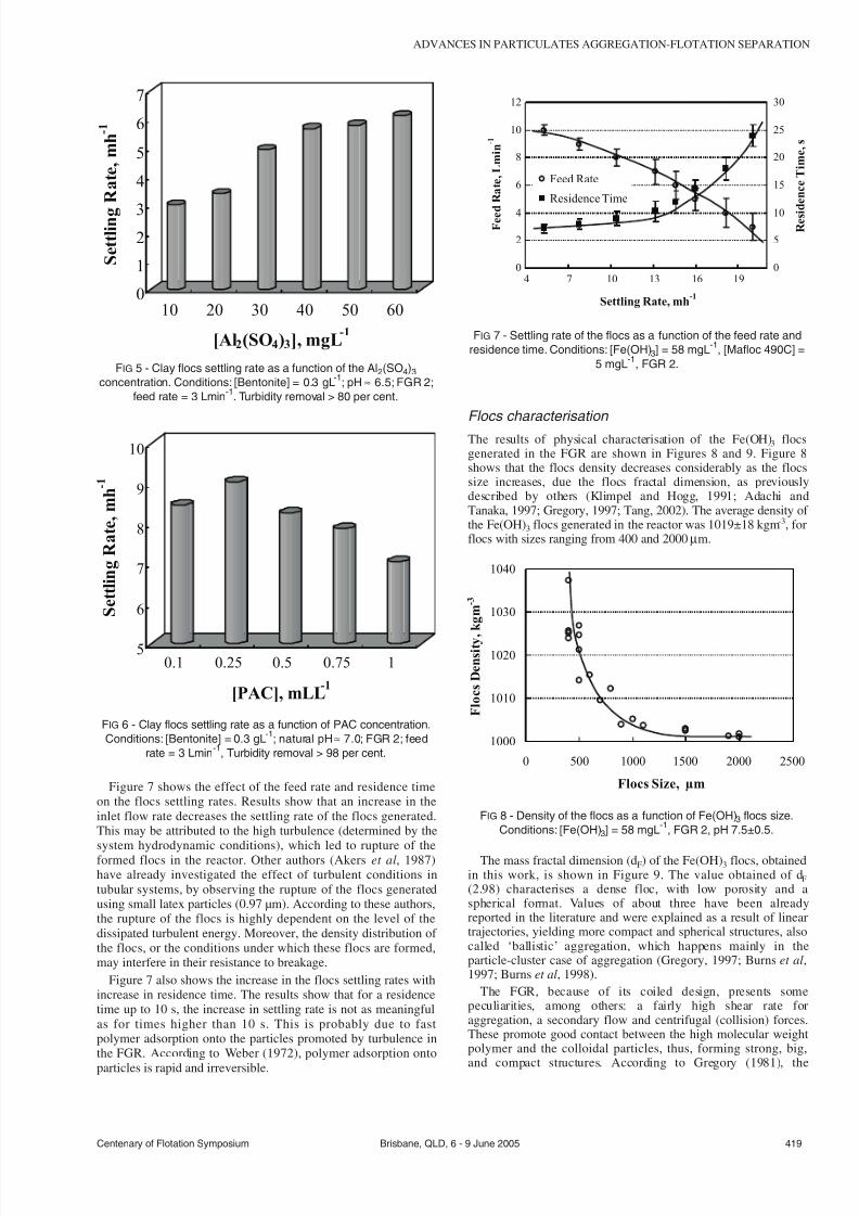
7232019 Advances in Particulates Aggregation-Flotation Separation
httpslidepdfcomreaderfulladvances-in-particulates-aggregation-flotation-separation 59
Figure 7 shows the effect of the feed rate and residence timeon the flocs settling rates Results show that an increase in theinlet flow rate decreases the settling rate of the flocs generatedThis may be attributed to the high turbulence (determined by thesystem hydrodynamic conditions) which led to rupture of theformed flocs in the reactor Other authors (Akers et al 1987)have already investigated the effect of turbulent conditions intubular systems by observing the rupture of the flocs generatedusing small latex particles (097 microm) According to these authorsthe rupture of the flocs is highly dependent on the level of thedissipated turbulent energy Moreover the density distribution of the flocs or the conditions under which these flocs are formedmay interfere in their resistance to breakage
Figure 7 also shows the increase in the flocs settling rates withincrease in residence time The results show that for a residencetime up to 10 s the increase in settling rate is not as meaningfulas for times higher than 10 s This is probably due to fastpolymer adsorption onto the particles promoted by turbulence inthe FGR According to Weber (1972) polymer adsorption onto
particles is rapid and irreversible
Flocs characterisation
The results of physical characterisation of the Fe(OH)3 flocsgenerated in the FGR are shown in Figures 8 and 9 Figure 8shows that the flocs density decreases considerably as the flocssize increases due the flocs fractal dimension as previouslydescribed by others (Klimpel and Hogg 1991 Adachi andTanaka 1997 Gregory 1997 Tang 2002) The average density of the Fe(OH)3 flocs generated in the reactor was 1019plusmn18 kgm-3 forflocs with sizes ranging from 400 and 2000 microm
The mass fractal dimension (dF) of the Fe(OH)3 flocs obtainedin this work is shown in Figure 9 The value obtained of dF(298) characterises a dense floc with low porosity and aspherical format Values of about three have been alreadyreported in the literature and were explained as a result of lineartrajectories yielding more compact and spherical structures alsocalled lsquoballisticrsquo aggregation which happens mainly in theparticle-cluster case of aggregation (Gregory 1997 Burns et al1997 Burns et al 1998)
The FGR because of its coiled design presents somepeculiarities among others a fairly high shear rate foraggregation a secondary flow and centrifugal (collision) forcesThese promote good contact between the high molecular weightpolymer and the colloidal particles thus forming strong big
and compact structures According to Gregory (1981) the
Centenary of Flotation Symposium Brisbane QLD 6 - 9 June 2005 419
ADVANCES IN PARTICULATES AGGREGATION-FLOTATION SEPARATION
0
1
2
3
4
5
6
7
S e t t l i n g
R a t e m h - 1
10 20 30 40 50 60
[Al2(SO4)3] mgL-1
FIG 5 - Clay flocs settling rate as a function of the Al2(SO4)3concentration Conditions [Bentonite] = 03 gL
-1 pH asymp 65 FGR 2
feed rate = 3 Lmin-1
Turbidity removal gt 80 per cent
5
6
7
8
9
10
S e t t l i n g R a t e m h - 1
01 025 05 075 1
[PAC] mLL-1
FIG 6 - Clay flocs settling rate as a function of PAC concentration
Conditions [Bentonite] = 03 gL-1
natural pH asymp 70 FGR 2 feed
rate = 3 Lmin-1
Turbidity removal gt 98 per cent
0
2
4
6
8
10
12
4 7 10 13 16 19
Settling Rate mh-1
F e e d R a t e L m i n - 1
0
5
10
15
20
25
30
R e s i d e n c e T i m e s
Feed Rate
Residence Time
FIG 7 - Settling rate of the flocs as a function of the feed rate and
residence time Conditions [Fe(OH)3] = 58 mgL-1
[Mafloc 490C] =
5 mgL-1
FGR 2
1000
1010
1020
1030
1040
0 500 1000 1500 2000 2500
Flocs Size microm
F l o c s D e n s i t y
k g m - 3
FIG 8 - Density of the flocs as a function of Fe(OH)3 flocs size
Conditions [Fe(OH)3] = 58 mgL-1
FGR 2 pH 75plusmn05
7232019 Advances in Particulates Aggregation-Flotation Separation
httpslidepdfcomreaderfulladvances-in-particulates-aggregation-flotation-separation 69
secondary flow introduced by the coiled tubes may affectflocculation in several ways most notably there would be anincrease in the pressure drop across the tube for a given flow ratecausing an increased average shear rate inside the tube improvingthe flocculation Besides the significant advantages presented byin-line mixing (Cariacutessimi and Rubio 2005) it may be betterexplored by winding the tubes into a helical coil The resultsappear to be shorter and more compact tube lsquoflocculatorsrsquo
The formation of aerated flocs and their flotation
In this system not only is flocculation favoured (due to higherturbulence) but also entrainment andor entrapment(enmeshment) of air bubbles inside the flocs leading toformation of large aerated units This phenomenon was observedvisually and is represented schematically in Figure 10 Theaerated flocs lsquofloatrsquo and are easily separated as a flotationproduct (named here as floc-flotation) Therefore the FGR in
this case serves at the same time as a flocculator and as abubblefloc contactor
Fe(OH) 3 polymer flocs
The effect of the reactor type was again evaluated through thedetermination of the flocs rising rates using the techniquedescribed (results are shown in Figure 11)
In all reactors the highest rising rates were obtained at a feedrate of 2 Lmin-1 with rates ranging from 67 to 112 mh-1 For feedrates above 2 Lmin-1 there was a decrease in the rising rate due tothe increase in turbulence caused by the increase of the inlet flowrate and the injection of microbubbles However using FGR 2the difference in the rising rates of the flocs for the feed rates
investigated is not so meaningful
FGR 2 presented the best results in terms of floc rising rate
(112 mh-1) and this reactor was chosen for further tests FGR 1showed poor efficiency due the short length which did not allowa sufficient residence time for floc formation FGRs 3 and 4presented a decrease in the rising rates probably due to ruptureof the flocs at all feed rates As previously mentioned flocs donot continue to grow indefinitely during prolonged shear butattain an equilibrium size
The variation of the flocs rising velocity according to theairsolids ratio is shown in Figure 12
Figure 12 shows that best results are obtained with anairsolids ratio greater than 0025 mlmg-1 Previous studies of flotation of colloidal hydroxide iron flocs showed iron removalefficiencies greater than 80 per cent with an airsolids ratio of 05(Shannon and Buisson 1980) Results obtained in this work atlower airsolids ratio may be explained in terms of increasedefficiency of collision adhesion attachment and entrapment of the bubbles inside or onto the flocs which does not occur in theconventional process of DAF According to Purchas (1977) theairsolids ratio is more related to the amount of air precipitatedand not to the quantity of air bubbles actually adhering to thefloating particles Thus the results obtained validate thefunctioning of the FGR as a bubbleparticle contactor enablingthe use of airsolids ratios much lower than those utilised in
conventional processes
420 Brisbane QLD 6 - 9 June 2005 Centenary of Flotation Symposium
E CARIacuteSSIMI and J RUBIO
Polymer
Effluent
Exit
Aerated FlocsPolymer
Air Microbubbles
Solids
Air
FIG 10 - Generation and growing of aerated flocs inside the FGR
85
90
95
100
105
110
115
R i s e R a t e m h -
2 4 6
Feed Rate Lmin-1
FGR 1
FGR 2
FGR 3
FGR 4
FIG 11 - Rise rate of the flocs as a function of feed rate and FGR
type Conditions [Fe(OH)3] = 58 mgL-1
[Mafloc 490C] = 5 mgL-1
air injection ratio = 50 per cent saturation pressure = 4 atm pH
75plusmn05
dF = 29828
1
2
3
4
25 27 29 31 33 35
log (flocs size)
l o g
( f l o c s m a s s )
FIG 9 - Fractal dimension of Fe(OH)3 flocs Conditions [Fe(OH)3] =
58 mgL-1
[Mafloc 490C] = 5 mgL-1
FGR 2 pH 75plusmn05
25
50
75
100
5
001 0015 002 0025 003 0035 004
Airsolids Ratio mLmg-1
R i s e R a t e m
h - 1
FIG 12 - Rise rate of the flocs as a function of the airsolids ratio
Conditions [Mafloc 490C] = 5 mgL-1
FGR 2 pH 75plusmn05
7232019 Advances in Particulates Aggregation-Flotation Separation
httpslidepdfcomreaderfulladvances-in-particulates-aggregation-flotation-separation 79
Comparative results obtained in this work revealed that theaerated separation rates are of the order of six times higher thanthe flocs settling rates The floating rates of the aerated flocsreaching values greater than 100 mh-1 are the result of the airvolume inside the floc structure plus the volume given by theadhered bubbles at the flocwater interface Accordinglycalculations of the equivalent diameter of bubbles which wouldgive such a rising rate were made and compared to the rising
(floating) flocs formed in the FGR (Figure 13)
The diameter of the equivalent bubbles calculated from theStokes equation for the rise rates of 67 to 112 mh-1 yielded anair bubble size (diameter) between 185 to 240 microm Because themicrobubbles injected measured experimentally (Rodrigues andRubio 2003) between 30 and 70 microm the only explanation forthis phenomenon is the air volume in the flocs Moreover thesevalues when compared to conventional DAF are much highermeaning that using the FGR as bubbles-flocs contactor may lead
to a very high capacity flotation system Some authors (Da Rosa2001 Rubio et al 2001 Haarhoff and Edzwald 2001) explainthe high rise rate in terms of the probability of bubble formationand rapid occlusion (entrapment) within flocs nucleation of bubbles at flocwater interfaces polymer coiling as a result of lsquosalting outrsquo effects at the aqueousair interface and plug flowmixing
Clay aerated aggregates
The rising rates of the aerated clay flocs using different dosagesof an anionic polyacrylamide are shown in Figure 14 Theconcentration of 05 mgL-1 showed the best rise results reachingvalues in the order of 115 mh-1 Results showed that higherpolymer doses are not efficient to increase the rise rate of the
clay flocs Overdose of the reagent (up to 05 mgL -1) reversed thesuperficial charge of the particles and prejudiced its aggregationThe rising rates of the aerated clay aggregates for different
doses of Al2(SO4)3 are shown in Figure 15 The best rise velocity(88 mh-1) is shown for the highest coagulant dosage (60 mgL -1)At high coagulant doses a higher concentration of Al(OH)3precipitates will be formed (pH 65) and the enmeshment of clayparticles by the precipitates and by the microbubbles will favourturbidity reduction
The rising rates of the aerated clay aggregates for differentdoses of PAC are shown in Figure 16 Results show that forhigher PAC doses the rising rate of the aggregates decreases Thelower PAC dose (025 mlL-1) showed the best rising velocity(98 mh-1) The rising rate probably decreases for higher PACdosages due to the large quantity of precipitates that aregenerated at these high reagent doses
Oil-in-water emulsion destabilisation
Destabilisation of a diesel oil emulsion employing Flonex 9045TM
polymer is shown in Figure 17 Results show that even the lower
dosage of the polymer flocculant (5 mgL-1) is enough todestabilise the emulsion with oil removal efficiencies reaching 90per cent Residual oil concentrations were about 6 - 9 mgL-1
In this case the effect of flocculation on the destabilisation of the oil emulsion was through the high turbulence promoted bythe FGR with velocity gradients up to 1400 s-1 (for a 3 Lmin-1
feed rate) (Cariacutessimi and Rubio 2005) The sodium lauryl ethersulfate surfactant used prior to the cationic polyacrylamideaddition allowed better oil removal results with low polymerdosages (Palanuwech and Coupland 2003)
CONCLUSIONS
An innovative in-line flocculation lsquohelicalrsquo unit named flocsgenerator reactor (FGR) was developed for the generation of
polymeric (aerated and non-aerated) flocs and oil-in-water
Centenary of Flotation Symposium Brisbane QLD 6 - 9 June 2005 421
ADVANCES IN PARTICULATES AGGREGATION-FLOTATION SEPARATION
180
200
220
240
65 75 85 95 105 115
Rise Rate mh -1
E q u i v a l e n t D i a m e t e r
m micro
FIG 13 - Equivalent diameter of bubbles as a function of the rise
rate (values obtained with the aerated flocs)
60
70
80
90
100
110
120
R i s e R
a t e m h -
025 05 1 2 4 6 8
[Anionic Polymer] mgL-1
FIG 14 - Clay rise rate as a function of [AH912SH] polymer
concentration Conditions [Bentonite] = 03 gL-1
natural pH asymp 70
FGR 2 feed rate = 3 Lmin-1
air injection ratio = 50 per cent
saturation pressure = 4 atm turbidity removal gt 88 per cent
60
65
70
75
80
85
90
R i s e R a t e m h - 1
10 20 30 40 50 60
[Al2(SO4)3] mgL-1
FIG 15 - Clay rise rate as a function of Al2(SO4)3 concentration
Conditions [Bentonite] = 03 gL-1
pH asymp 65 FGR 2 feed rate =
3 Lmin-1
air injection ratio = 50 per cent saturation pressure =
4 atm turbidity removal gt93 per cent
7232019 Advances in Particulates Aggregation-Flotation Separation
httpslidepdfcomreaderfulladvances-in-particulates-aggregation-flotation-separation 89
destabilisation The studies showed high efficiency for thegeneration of Fe(OH)3 and clay flocs with the employment of high molecular weight polymers The polymer flocs obtainedwere well structured large and the Fe(OH)3 flocs presented afractal dimension of 298 characteristic of dense flocs with lowporosity and spherical format The FGR may also be used as afloc-bubble contactor to generate large aerated flocs (5 - 8 mm)
The FGR appears to have some advantages for the formation of polymer flocs namely suitable flow mixing absence of short-circuits or dead zones plug flow profile low arearequirement absence of moving parts simple design and lowmechanical and electrical energy needs Solid-liquid separationof the flocs by settling reached rates of about 18 - 24 mh-1
compared to more than 100 mh-1 rise rate for aerated flocs Thesevalues are higher than those found in conventional sedimentationor DAF units The FGR appears to have good potential as alsquoflocculatorrsquo (or flotation)-separator device in applicationsrequiring high rate solid-liquid separations Successful examplesof emulsified oil and solids removal from water were shown andbecause in all cases efficiencies were high (gt90 per centremoval) it is believed that this kind of flocculation-flotationappears to have a great potential in solid-liquid or liquid-liquid
separation
ACKNOWLEDGEMENTS
The authors thank all the colleagues at Laboratoacuterio deTecnologia Mineral e Ambiental (LTM) at UFRGS for theirassistance and friendly atmosphere and to all institutionssupporting research in Brazil especially CNPq (Institute of Millennium Project)
REFERENCESAdachi Y and Tanaka Y 1997 Settling velocity of an aluminium-kaolinit
floc Water Science and Technology 31(3)449-454Bio 2002 Flotaccedilatildeo ganha adeptos no Brasil Revista Brasileira de
Saneamento e Meio Ambiente JulySeptember pp 40-47 (inPortuguese)
Burns J L Yan Y D Jameson G J and Biggs S A 1997 A lightscattering study of the fractal aggregation behavior of a modelcolloidal system Langmuir 136413-6420
Burns J L Yan Y D Jameson G J and Biggs S A 1998 A comparisonof the fractal properties of salt-aggregated and polymer-flocculatedcolloidal particles Progress in Colloid and Polymer Science11070-75
Cariacutessimi E and Rubio J 2005 The flocs generator reactor ndash FGR anew basis for flocculation and solid-liquid separation International Journal of Mineral Processing 75(3-4)237-247
Costa C A and Rubio J 2005 Deinking flotation influence of calciumsoap and surface-active substances Minerals Engineering18(1)59-64
Crockett J and Muntisov M 1995 Potable water treatment by dissolvedair flotationfiltration in Proceedings Modern Techniques in Water and Wastewater Treatment (eds L O Kolarik and A J Priestley) pp15-18
Da Rosa J J 2001 Tratamento de efluentes oleosos por floculaccedilatildeopneumaacutetica em linha e separaccedilatildeo por flotaccedilatildeo Processo FF ThesisUFRGSPPGEM Jorge Rubio 126 p (in Portuguese)
Edzwald J K 1995 Principles and applications of dissolved air flotationWater Science and Technology 31(3-4)1-23
Feacuteris L A Gallina C W Rodrigues R T and Rubio J 2001 Optimizingdissolved air flotation design and saturation Water Science and Technology 43(8)153-157
Filho A C T P and Brandno C C S 2001 Evaluation of flocculation anddissolved air flotation as an advanced wastewater treatment Water Science and Technology 43(8)91-98
Finch J A 1995 Column flotation a selected review-part IV flotationdevices Minerals Engineering 8(6)587-602
Finch J A and Hardie C A 1999 An example of innovation from thewaste management industry deinking flotation cells Minerals Engineering 12(5)467-475
Gregory J 1981 Flocculation in laminar tube flow Chemical Engineering Science 36(11)1789-1794
Gregory J 1988 Polymer adsorption and flocculation in shearedsuspensions Colloids and Surfaces 31231-253
Gregory J 1997 The density of particle aggregates Water Science and Technology 36(4)1-13
Gregory J 1998 The role of floc density in solid-liquid separationFiltration and Separation 35(4)367-371
Haarhoff J and Edzwald J K 2001 Modelling of floc-bubble aggregaterise rates in dissolved air flotation Water Science and Technology43(8)175-184
Harbort G J Jackson B R and Manlapig E V 1994 Recent advances inJameson flotation cell technology Minerals Engineering7(2-3)319-332
Kempeneers S Menxel F V and Gille L 2001 A decade of largeexperience in dissolved air flotation Water Science and Technology43(8)35-41
Kiuru H J 2001 Development of dissolved air flotation technology fromthe first generation to the newest (third) one (DAF in turbulent flowconditions) Water Science and Technology 43(8)1-7
Klimpel R C and Hogg R 1991 Evaluation of floc structures Colloidsand Surfaces 55279-288
Liers S Baeyens J and Mochtar I 1996 Modelling dissolved airflotation Water Environment Research 68(6)1061-1075
422 Brisbane QLD 6 - 9 June 2005 Centenary of Flotation Symposium
E CARIacuteSSIMI and J RUBIO
0
20
40
60
80
100
0 20 40 60
[Cationic Polymer] mgL-1
O i l r e m o v a l
0
20
40
60
80
100
O i l R e s i d u a l m g L - 1
Oil Removal
Oil Residual
FIG 17 - Diesel oil emulsion flocculation (destabilisation) with
Flonex 9045 polymer Conditions [ow emulsion] = 100 mgL-1
[sodium lauryl ether sulfate] = 1 mgL-1
temperature = 20degC FGR
2 feed rate = 3 Lmin-1
80
85
90
95
100
R i s e R a t e m h - 1
01 025 05 075 1
[PAC] mLL-1
FIG 16 - Clay rise rates as a function of the PAC concentration
Conditions [Bentonite] = 03 gL-1
natural pH asymp 70 FGR 2 feed
rate = 3 Lmin-1
air injection ratio = 50 per cent saturation
pressure = 4 atm turbidity removal gt98 per cent
7232019 Advances in Particulates Aggregation-Flotation Separation
httpslidepdfcomreaderfulladvances-in-particulates-aggregation-flotation-separation 99
Matis K A and Lazaridis N K 2002 Flotation techniques in watertechnology for metals recovery dispersed-air versus dissolved-airflotation J Min Metall A381-27
Matis K A 1995 Flotation Science and Engineering 584 p (MarcelDekker New York)
Matis K A Zouboulis A I Gallios G P Erwe T and Bloumlcher C 2004Application of flotation for the separation of metal-loaded zeolitesChemosphere 5565-72
Mavros P and Matis K A (eds) 1992 Innovations in Flotation
Technology (Kluwer Academic Publishers Dordrecht)Montgomery D C 1991 Design and Analysis of Experiments third
edition 649 p (John Wiley and Sons Inc Canada)Oslashdegaard H 2001 The use of dissolved air flotation in municipal
wastewater treatment Water Science and Technology 43(8)83-90Oliveira J C 2004 Tecnologia para despoluir o rio Pinheiros
Saneamento Ambiental 10868 (in Portuguese)Owen J J Morse D E Morse W O and Jovine R 1999 New
developments in flotation equipment for water treatment systems in Advances in Flotation Technology (eds B K Parekh and J D Miller)pp 381-389 (Society for Mining Metallurgy and Exploration Inc(SME) Littleton)
Palanuweck J and Coupland J N 2003 Effect of surfactant type on thestability of oil-in-water emulsions to dispersed phase crystallizationColloids and Surfaces A Physicochemical and Engineering Aspects223251-262
Parekh B K and Miller J D (eds) 1999 Advances in FlotationTechnology (Society for Mining Metallurgy and Exploration Inc(SME) Littleton)
Purchas D B 1977 SolidLiquid Separation Equipment Scale Up 584 p(Upland Press Ltd)
Reali M A P and Marchetto M 2001 High-rate dissolved air flotationfor water treatment Water Science and Technology 43(8)51-57
Rodrigues R T and Rubio J 2003 New basis for measuring the sizedistribution of bubbles Minerals Engineering 16757-765
Rosa J J and Rubio J 2005 The FF (flocculation-flotation) process Minerals Engineering 18(7)701-707
Rubio J 1998 Environmental applications of the flotation process in Effluent Treatment in the Mining Industry (eds S H Castro F Vergaraand M Sanchez) Chapter 8 pp 335-364 (University of Concepcioacuten-Chile Chile)
Rubio J 2003 Unconventional flocculation and flotation in ProceedingsFlotation and Flocculation From Fundamentals to ApplicationsStrategic Conference and Workshop Hawaii (eds J Ralston J Miller
and J Rubio) pp 17-32Rubio J Souza M L and Smith R W 2002 Overview of flotation as a
wastewater treatment technique Minerals Engineering 15139-155Rubio J Tessele F Porcile P A and Marinkovic E 2001 Flotacioacuten
como proceso de remocioacuten de contaminantes I Principios baacutesicosteacutecnicas y aplicaciones Minerales 56(242)9-18 (in Spanish)
Schofield T 2001 Dissolved air flotation in drinking water productionWater Science and Technology 43(8)9-18
Shannon W T and Buisson D H 1980 Dissolved air flotation in hotwater Water Research 14(7)759-765
Tang P Greenwood J and Raper A 2002 A model to describe thesettling behavior or fractal aggregates Journal of Colloid and Interface Science 247210-219
Voronin N N and Dibrov I A 1998 Classification of flotation processesin wastewater decontamination Journal of Environmental Engineering 124(5)469-472
Weber W J 1972 Physicochemical Processes for Water Quality Control640 p (Wiley-Interscience New York-USA)
Weir S and Moody G M 2003 The importance of flocculant choice withconsideration to mixing energy to achieve efficient solidliquidseparation Minerals Engineering 16(2)109-113
Zhou Z A Zhenghe Xu and Finch J A 1994 On the role of cavitationin particle collection during flotation ndash a critical review Minerals Engineering 7(9)1073-1084
Centenary of Flotation Symposium Brisbane QLD 6 - 9 June 2005 423
ADVANCES IN PARTICULATES AGGREGATION-FLOTATION SEPARATION
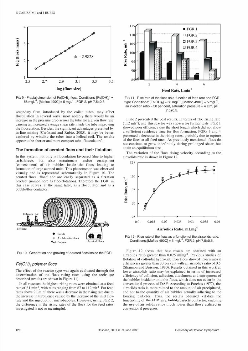
7232019 Advances in Particulates Aggregation-Flotation Separation
httpslidepdfcomreaderfulladvances-in-particulates-aggregation-flotation-separation 69
secondary flow introduced by the coiled tubes may affectflocculation in several ways most notably there would be anincrease in the pressure drop across the tube for a given flow ratecausing an increased average shear rate inside the tube improvingthe flocculation Besides the significant advantages presented byin-line mixing (Cariacutessimi and Rubio 2005) it may be betterexplored by winding the tubes into a helical coil The resultsappear to be shorter and more compact tube lsquoflocculatorsrsquo
The formation of aerated flocs and their flotation
In this system not only is flocculation favoured (due to higherturbulence) but also entrainment andor entrapment(enmeshment) of air bubbles inside the flocs leading toformation of large aerated units This phenomenon was observedvisually and is represented schematically in Figure 10 Theaerated flocs lsquofloatrsquo and are easily separated as a flotationproduct (named here as floc-flotation) Therefore the FGR in
this case serves at the same time as a flocculator and as abubblefloc contactor
Fe(OH) 3 polymer flocs
The effect of the reactor type was again evaluated through thedetermination of the flocs rising rates using the techniquedescribed (results are shown in Figure 11)
In all reactors the highest rising rates were obtained at a feedrate of 2 Lmin-1 with rates ranging from 67 to 112 mh-1 For feedrates above 2 Lmin-1 there was a decrease in the rising rate due tothe increase in turbulence caused by the increase of the inlet flowrate and the injection of microbubbles However using FGR 2the difference in the rising rates of the flocs for the feed rates
investigated is not so meaningful
FGR 2 presented the best results in terms of floc rising rate
(112 mh-1) and this reactor was chosen for further tests FGR 1showed poor efficiency due the short length which did not allowa sufficient residence time for floc formation FGRs 3 and 4presented a decrease in the rising rates probably due to ruptureof the flocs at all feed rates As previously mentioned flocs donot continue to grow indefinitely during prolonged shear butattain an equilibrium size
The variation of the flocs rising velocity according to theairsolids ratio is shown in Figure 12
Figure 12 shows that best results are obtained with anairsolids ratio greater than 0025 mlmg-1 Previous studies of flotation of colloidal hydroxide iron flocs showed iron removalefficiencies greater than 80 per cent with an airsolids ratio of 05(Shannon and Buisson 1980) Results obtained in this work atlower airsolids ratio may be explained in terms of increasedefficiency of collision adhesion attachment and entrapment of the bubbles inside or onto the flocs which does not occur in theconventional process of DAF According to Purchas (1977) theairsolids ratio is more related to the amount of air precipitatedand not to the quantity of air bubbles actually adhering to thefloating particles Thus the results obtained validate thefunctioning of the FGR as a bubbleparticle contactor enablingthe use of airsolids ratios much lower than those utilised in
conventional processes
420 Brisbane QLD 6 - 9 June 2005 Centenary of Flotation Symposium
E CARIacuteSSIMI and J RUBIO
Polymer
Effluent
Exit
Aerated FlocsPolymer
Air Microbubbles
Solids
Air
FIG 10 - Generation and growing of aerated flocs inside the FGR
85
90
95
100
105
110
115
R i s e R a t e m h -
2 4 6
Feed Rate Lmin-1
FGR 1
FGR 2
FGR 3
FGR 4
FIG 11 - Rise rate of the flocs as a function of feed rate and FGR
type Conditions [Fe(OH)3] = 58 mgL-1
[Mafloc 490C] = 5 mgL-1
air injection ratio = 50 per cent saturation pressure = 4 atm pH
75plusmn05
dF = 29828
1
2
3
4
25 27 29 31 33 35
log (flocs size)
l o g
( f l o c s m a s s )
FIG 9 - Fractal dimension of Fe(OH)3 flocs Conditions [Fe(OH)3] =
58 mgL-1
[Mafloc 490C] = 5 mgL-1
FGR 2 pH 75plusmn05
25
50
75
100
5
001 0015 002 0025 003 0035 004
Airsolids Ratio mLmg-1
R i s e R a t e m
h - 1
FIG 12 - Rise rate of the flocs as a function of the airsolids ratio
Conditions [Mafloc 490C] = 5 mgL-1
FGR 2 pH 75plusmn05
7232019 Advances in Particulates Aggregation-Flotation Separation
httpslidepdfcomreaderfulladvances-in-particulates-aggregation-flotation-separation 79
Comparative results obtained in this work revealed that theaerated separation rates are of the order of six times higher thanthe flocs settling rates The floating rates of the aerated flocsreaching values greater than 100 mh-1 are the result of the airvolume inside the floc structure plus the volume given by theadhered bubbles at the flocwater interface Accordinglycalculations of the equivalent diameter of bubbles which wouldgive such a rising rate were made and compared to the rising
(floating) flocs formed in the FGR (Figure 13)
The diameter of the equivalent bubbles calculated from theStokes equation for the rise rates of 67 to 112 mh-1 yielded anair bubble size (diameter) between 185 to 240 microm Because themicrobubbles injected measured experimentally (Rodrigues andRubio 2003) between 30 and 70 microm the only explanation forthis phenomenon is the air volume in the flocs Moreover thesevalues when compared to conventional DAF are much highermeaning that using the FGR as bubbles-flocs contactor may lead
to a very high capacity flotation system Some authors (Da Rosa2001 Rubio et al 2001 Haarhoff and Edzwald 2001) explainthe high rise rate in terms of the probability of bubble formationand rapid occlusion (entrapment) within flocs nucleation of bubbles at flocwater interfaces polymer coiling as a result of lsquosalting outrsquo effects at the aqueousair interface and plug flowmixing
Clay aerated aggregates
The rising rates of the aerated clay flocs using different dosagesof an anionic polyacrylamide are shown in Figure 14 Theconcentration of 05 mgL-1 showed the best rise results reachingvalues in the order of 115 mh-1 Results showed that higherpolymer doses are not efficient to increase the rise rate of the
clay flocs Overdose of the reagent (up to 05 mgL -1) reversed thesuperficial charge of the particles and prejudiced its aggregationThe rising rates of the aerated clay aggregates for different
doses of Al2(SO4)3 are shown in Figure 15 The best rise velocity(88 mh-1) is shown for the highest coagulant dosage (60 mgL -1)At high coagulant doses a higher concentration of Al(OH)3precipitates will be formed (pH 65) and the enmeshment of clayparticles by the precipitates and by the microbubbles will favourturbidity reduction
The rising rates of the aerated clay aggregates for differentdoses of PAC are shown in Figure 16 Results show that forhigher PAC doses the rising rate of the aggregates decreases Thelower PAC dose (025 mlL-1) showed the best rising velocity(98 mh-1) The rising rate probably decreases for higher PACdosages due to the large quantity of precipitates that aregenerated at these high reagent doses
Oil-in-water emulsion destabilisation
Destabilisation of a diesel oil emulsion employing Flonex 9045TM
polymer is shown in Figure 17 Results show that even the lower
dosage of the polymer flocculant (5 mgL-1) is enough todestabilise the emulsion with oil removal efficiencies reaching 90per cent Residual oil concentrations were about 6 - 9 mgL-1
In this case the effect of flocculation on the destabilisation of the oil emulsion was through the high turbulence promoted bythe FGR with velocity gradients up to 1400 s-1 (for a 3 Lmin-1
feed rate) (Cariacutessimi and Rubio 2005) The sodium lauryl ethersulfate surfactant used prior to the cationic polyacrylamideaddition allowed better oil removal results with low polymerdosages (Palanuwech and Coupland 2003)
CONCLUSIONS
An innovative in-line flocculation lsquohelicalrsquo unit named flocsgenerator reactor (FGR) was developed for the generation of
polymeric (aerated and non-aerated) flocs and oil-in-water
Centenary of Flotation Symposium Brisbane QLD 6 - 9 June 2005 421
ADVANCES IN PARTICULATES AGGREGATION-FLOTATION SEPARATION
180
200
220
240
65 75 85 95 105 115
Rise Rate mh -1
E q u i v a l e n t D i a m e t e r
m micro
FIG 13 - Equivalent diameter of bubbles as a function of the rise
rate (values obtained with the aerated flocs)
60
70
80
90
100
110
120
R i s e R
a t e m h -
025 05 1 2 4 6 8
[Anionic Polymer] mgL-1
FIG 14 - Clay rise rate as a function of [AH912SH] polymer
concentration Conditions [Bentonite] = 03 gL-1
natural pH asymp 70
FGR 2 feed rate = 3 Lmin-1
air injection ratio = 50 per cent
saturation pressure = 4 atm turbidity removal gt 88 per cent
60
65
70
75
80
85
90
R i s e R a t e m h - 1
10 20 30 40 50 60
[Al2(SO4)3] mgL-1
FIG 15 - Clay rise rate as a function of Al2(SO4)3 concentration
Conditions [Bentonite] = 03 gL-1
pH asymp 65 FGR 2 feed rate =
3 Lmin-1
air injection ratio = 50 per cent saturation pressure =
4 atm turbidity removal gt93 per cent
7232019 Advances in Particulates Aggregation-Flotation Separation
httpslidepdfcomreaderfulladvances-in-particulates-aggregation-flotation-separation 89
destabilisation The studies showed high efficiency for thegeneration of Fe(OH)3 and clay flocs with the employment of high molecular weight polymers The polymer flocs obtainedwere well structured large and the Fe(OH)3 flocs presented afractal dimension of 298 characteristic of dense flocs with lowporosity and spherical format The FGR may also be used as afloc-bubble contactor to generate large aerated flocs (5 - 8 mm)
The FGR appears to have some advantages for the formation of polymer flocs namely suitable flow mixing absence of short-circuits or dead zones plug flow profile low arearequirement absence of moving parts simple design and lowmechanical and electrical energy needs Solid-liquid separationof the flocs by settling reached rates of about 18 - 24 mh-1
compared to more than 100 mh-1 rise rate for aerated flocs Thesevalues are higher than those found in conventional sedimentationor DAF units The FGR appears to have good potential as alsquoflocculatorrsquo (or flotation)-separator device in applicationsrequiring high rate solid-liquid separations Successful examplesof emulsified oil and solids removal from water were shown andbecause in all cases efficiencies were high (gt90 per centremoval) it is believed that this kind of flocculation-flotationappears to have a great potential in solid-liquid or liquid-liquid
separation
ACKNOWLEDGEMENTS
The authors thank all the colleagues at Laboratoacuterio deTecnologia Mineral e Ambiental (LTM) at UFRGS for theirassistance and friendly atmosphere and to all institutionssupporting research in Brazil especially CNPq (Institute of Millennium Project)
REFERENCESAdachi Y and Tanaka Y 1997 Settling velocity of an aluminium-kaolinit
floc Water Science and Technology 31(3)449-454Bio 2002 Flotaccedilatildeo ganha adeptos no Brasil Revista Brasileira de
Saneamento e Meio Ambiente JulySeptember pp 40-47 (inPortuguese)
Burns J L Yan Y D Jameson G J and Biggs S A 1997 A lightscattering study of the fractal aggregation behavior of a modelcolloidal system Langmuir 136413-6420
Burns J L Yan Y D Jameson G J and Biggs S A 1998 A comparisonof the fractal properties of salt-aggregated and polymer-flocculatedcolloidal particles Progress in Colloid and Polymer Science11070-75
Cariacutessimi E and Rubio J 2005 The flocs generator reactor ndash FGR anew basis for flocculation and solid-liquid separation International Journal of Mineral Processing 75(3-4)237-247
Costa C A and Rubio J 2005 Deinking flotation influence of calciumsoap and surface-active substances Minerals Engineering18(1)59-64
Crockett J and Muntisov M 1995 Potable water treatment by dissolvedair flotationfiltration in Proceedings Modern Techniques in Water and Wastewater Treatment (eds L O Kolarik and A J Priestley) pp15-18
Da Rosa J J 2001 Tratamento de efluentes oleosos por floculaccedilatildeopneumaacutetica em linha e separaccedilatildeo por flotaccedilatildeo Processo FF ThesisUFRGSPPGEM Jorge Rubio 126 p (in Portuguese)
Edzwald J K 1995 Principles and applications of dissolved air flotationWater Science and Technology 31(3-4)1-23
Feacuteris L A Gallina C W Rodrigues R T and Rubio J 2001 Optimizingdissolved air flotation design and saturation Water Science and Technology 43(8)153-157
Filho A C T P and Brandno C C S 2001 Evaluation of flocculation anddissolved air flotation as an advanced wastewater treatment Water Science and Technology 43(8)91-98
Finch J A 1995 Column flotation a selected review-part IV flotationdevices Minerals Engineering 8(6)587-602
Finch J A and Hardie C A 1999 An example of innovation from thewaste management industry deinking flotation cells Minerals Engineering 12(5)467-475
Gregory J 1981 Flocculation in laminar tube flow Chemical Engineering Science 36(11)1789-1794
Gregory J 1988 Polymer adsorption and flocculation in shearedsuspensions Colloids and Surfaces 31231-253
Gregory J 1997 The density of particle aggregates Water Science and Technology 36(4)1-13
Gregory J 1998 The role of floc density in solid-liquid separationFiltration and Separation 35(4)367-371
Haarhoff J and Edzwald J K 2001 Modelling of floc-bubble aggregaterise rates in dissolved air flotation Water Science and Technology43(8)175-184
Harbort G J Jackson B R and Manlapig E V 1994 Recent advances inJameson flotation cell technology Minerals Engineering7(2-3)319-332
Kempeneers S Menxel F V and Gille L 2001 A decade of largeexperience in dissolved air flotation Water Science and Technology43(8)35-41
Kiuru H J 2001 Development of dissolved air flotation technology fromthe first generation to the newest (third) one (DAF in turbulent flowconditions) Water Science and Technology 43(8)1-7
Klimpel R C and Hogg R 1991 Evaluation of floc structures Colloidsand Surfaces 55279-288
Liers S Baeyens J and Mochtar I 1996 Modelling dissolved airflotation Water Environment Research 68(6)1061-1075
422 Brisbane QLD 6 - 9 June 2005 Centenary of Flotation Symposium
E CARIacuteSSIMI and J RUBIO
0
20
40
60
80
100
0 20 40 60
[Cationic Polymer] mgL-1
O i l r e m o v a l
0
20
40
60
80
100
O i l R e s i d u a l m g L - 1
Oil Removal
Oil Residual
FIG 17 - Diesel oil emulsion flocculation (destabilisation) with
Flonex 9045 polymer Conditions [ow emulsion] = 100 mgL-1
[sodium lauryl ether sulfate] = 1 mgL-1
temperature = 20degC FGR
2 feed rate = 3 Lmin-1
80
85
90
95
100
R i s e R a t e m h - 1
01 025 05 075 1
[PAC] mLL-1
FIG 16 - Clay rise rates as a function of the PAC concentration
Conditions [Bentonite] = 03 gL-1
natural pH asymp 70 FGR 2 feed
rate = 3 Lmin-1
air injection ratio = 50 per cent saturation
pressure = 4 atm turbidity removal gt98 per cent
7232019 Advances in Particulates Aggregation-Flotation Separation
httpslidepdfcomreaderfulladvances-in-particulates-aggregation-flotation-separation 99
Matis K A and Lazaridis N K 2002 Flotation techniques in watertechnology for metals recovery dispersed-air versus dissolved-airflotation J Min Metall A381-27
Matis K A 1995 Flotation Science and Engineering 584 p (MarcelDekker New York)
Matis K A Zouboulis A I Gallios G P Erwe T and Bloumlcher C 2004Application of flotation for the separation of metal-loaded zeolitesChemosphere 5565-72
Mavros P and Matis K A (eds) 1992 Innovations in Flotation
Technology (Kluwer Academic Publishers Dordrecht)Montgomery D C 1991 Design and Analysis of Experiments third
edition 649 p (John Wiley and Sons Inc Canada)Oslashdegaard H 2001 The use of dissolved air flotation in municipal
wastewater treatment Water Science and Technology 43(8)83-90Oliveira J C 2004 Tecnologia para despoluir o rio Pinheiros
Saneamento Ambiental 10868 (in Portuguese)Owen J J Morse D E Morse W O and Jovine R 1999 New
developments in flotation equipment for water treatment systems in Advances in Flotation Technology (eds B K Parekh and J D Miller)pp 381-389 (Society for Mining Metallurgy and Exploration Inc(SME) Littleton)
Palanuweck J and Coupland J N 2003 Effect of surfactant type on thestability of oil-in-water emulsions to dispersed phase crystallizationColloids and Surfaces A Physicochemical and Engineering Aspects223251-262
Parekh B K and Miller J D (eds) 1999 Advances in FlotationTechnology (Society for Mining Metallurgy and Exploration Inc(SME) Littleton)
Purchas D B 1977 SolidLiquid Separation Equipment Scale Up 584 p(Upland Press Ltd)
Reali M A P and Marchetto M 2001 High-rate dissolved air flotationfor water treatment Water Science and Technology 43(8)51-57
Rodrigues R T and Rubio J 2003 New basis for measuring the sizedistribution of bubbles Minerals Engineering 16757-765
Rosa J J and Rubio J 2005 The FF (flocculation-flotation) process Minerals Engineering 18(7)701-707
Rubio J 1998 Environmental applications of the flotation process in Effluent Treatment in the Mining Industry (eds S H Castro F Vergaraand M Sanchez) Chapter 8 pp 335-364 (University of Concepcioacuten-Chile Chile)
Rubio J 2003 Unconventional flocculation and flotation in ProceedingsFlotation and Flocculation From Fundamentals to ApplicationsStrategic Conference and Workshop Hawaii (eds J Ralston J Miller
and J Rubio) pp 17-32Rubio J Souza M L and Smith R W 2002 Overview of flotation as a
wastewater treatment technique Minerals Engineering 15139-155Rubio J Tessele F Porcile P A and Marinkovic E 2001 Flotacioacuten
como proceso de remocioacuten de contaminantes I Principios baacutesicosteacutecnicas y aplicaciones Minerales 56(242)9-18 (in Spanish)
Schofield T 2001 Dissolved air flotation in drinking water productionWater Science and Technology 43(8)9-18
Shannon W T and Buisson D H 1980 Dissolved air flotation in hotwater Water Research 14(7)759-765
Tang P Greenwood J and Raper A 2002 A model to describe thesettling behavior or fractal aggregates Journal of Colloid and Interface Science 247210-219
Voronin N N and Dibrov I A 1998 Classification of flotation processesin wastewater decontamination Journal of Environmental Engineering 124(5)469-472
Weber W J 1972 Physicochemical Processes for Water Quality Control640 p (Wiley-Interscience New York-USA)
Weir S and Moody G M 2003 The importance of flocculant choice withconsideration to mixing energy to achieve efficient solidliquidseparation Minerals Engineering 16(2)109-113
Zhou Z A Zhenghe Xu and Finch J A 1994 On the role of cavitationin particle collection during flotation ndash a critical review Minerals Engineering 7(9)1073-1084
Centenary of Flotation Symposium Brisbane QLD 6 - 9 June 2005 423
ADVANCES IN PARTICULATES AGGREGATION-FLOTATION SEPARATION
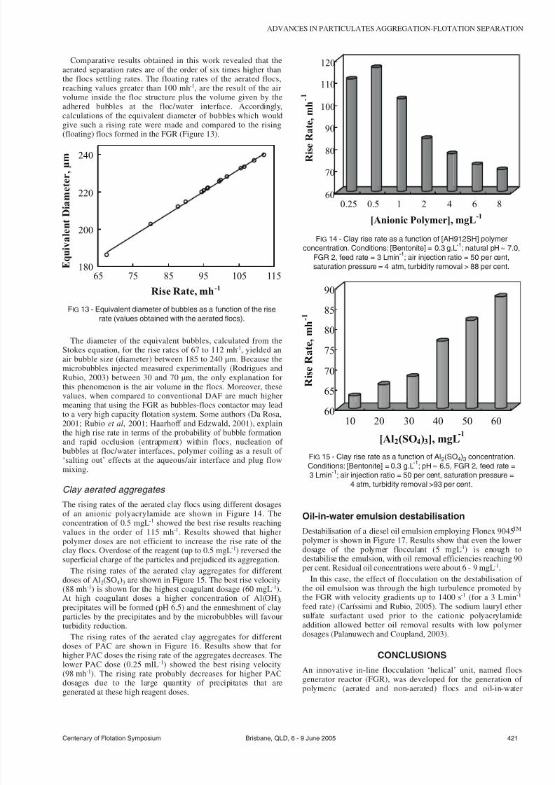
7232019 Advances in Particulates Aggregation-Flotation Separation
httpslidepdfcomreaderfulladvances-in-particulates-aggregation-flotation-separation 79
Comparative results obtained in this work revealed that theaerated separation rates are of the order of six times higher thanthe flocs settling rates The floating rates of the aerated flocsreaching values greater than 100 mh-1 are the result of the airvolume inside the floc structure plus the volume given by theadhered bubbles at the flocwater interface Accordinglycalculations of the equivalent diameter of bubbles which wouldgive such a rising rate were made and compared to the rising
(floating) flocs formed in the FGR (Figure 13)
The diameter of the equivalent bubbles calculated from theStokes equation for the rise rates of 67 to 112 mh-1 yielded anair bubble size (diameter) between 185 to 240 microm Because themicrobubbles injected measured experimentally (Rodrigues andRubio 2003) between 30 and 70 microm the only explanation forthis phenomenon is the air volume in the flocs Moreover thesevalues when compared to conventional DAF are much highermeaning that using the FGR as bubbles-flocs contactor may lead
to a very high capacity flotation system Some authors (Da Rosa2001 Rubio et al 2001 Haarhoff and Edzwald 2001) explainthe high rise rate in terms of the probability of bubble formationand rapid occlusion (entrapment) within flocs nucleation of bubbles at flocwater interfaces polymer coiling as a result of lsquosalting outrsquo effects at the aqueousair interface and plug flowmixing
Clay aerated aggregates
The rising rates of the aerated clay flocs using different dosagesof an anionic polyacrylamide are shown in Figure 14 Theconcentration of 05 mgL-1 showed the best rise results reachingvalues in the order of 115 mh-1 Results showed that higherpolymer doses are not efficient to increase the rise rate of the
clay flocs Overdose of the reagent (up to 05 mgL -1) reversed thesuperficial charge of the particles and prejudiced its aggregationThe rising rates of the aerated clay aggregates for different
doses of Al2(SO4)3 are shown in Figure 15 The best rise velocity(88 mh-1) is shown for the highest coagulant dosage (60 mgL -1)At high coagulant doses a higher concentration of Al(OH)3precipitates will be formed (pH 65) and the enmeshment of clayparticles by the precipitates and by the microbubbles will favourturbidity reduction
The rising rates of the aerated clay aggregates for differentdoses of PAC are shown in Figure 16 Results show that forhigher PAC doses the rising rate of the aggregates decreases Thelower PAC dose (025 mlL-1) showed the best rising velocity(98 mh-1) The rising rate probably decreases for higher PACdosages due to the large quantity of precipitates that aregenerated at these high reagent doses
Oil-in-water emulsion destabilisation
Destabilisation of a diesel oil emulsion employing Flonex 9045TM
polymer is shown in Figure 17 Results show that even the lower
dosage of the polymer flocculant (5 mgL-1) is enough todestabilise the emulsion with oil removal efficiencies reaching 90per cent Residual oil concentrations were about 6 - 9 mgL-1
In this case the effect of flocculation on the destabilisation of the oil emulsion was through the high turbulence promoted bythe FGR with velocity gradients up to 1400 s-1 (for a 3 Lmin-1
feed rate) (Cariacutessimi and Rubio 2005) The sodium lauryl ethersulfate surfactant used prior to the cationic polyacrylamideaddition allowed better oil removal results with low polymerdosages (Palanuwech and Coupland 2003)
CONCLUSIONS
An innovative in-line flocculation lsquohelicalrsquo unit named flocsgenerator reactor (FGR) was developed for the generation of
polymeric (aerated and non-aerated) flocs and oil-in-water
Centenary of Flotation Symposium Brisbane QLD 6 - 9 June 2005 421
ADVANCES IN PARTICULATES AGGREGATION-FLOTATION SEPARATION
180
200
220
240
65 75 85 95 105 115
Rise Rate mh -1
E q u i v a l e n t D i a m e t e r
m micro
FIG 13 - Equivalent diameter of bubbles as a function of the rise
rate (values obtained with the aerated flocs)
60
70
80
90
100
110
120
R i s e R
a t e m h -
025 05 1 2 4 6 8
[Anionic Polymer] mgL-1
FIG 14 - Clay rise rate as a function of [AH912SH] polymer
concentration Conditions [Bentonite] = 03 gL-1
natural pH asymp 70
FGR 2 feed rate = 3 Lmin-1
air injection ratio = 50 per cent
saturation pressure = 4 atm turbidity removal gt 88 per cent
60
65
70
75
80
85
90
R i s e R a t e m h - 1
10 20 30 40 50 60
[Al2(SO4)3] mgL-1
FIG 15 - Clay rise rate as a function of Al2(SO4)3 concentration
Conditions [Bentonite] = 03 gL-1
pH asymp 65 FGR 2 feed rate =
3 Lmin-1
air injection ratio = 50 per cent saturation pressure =
4 atm turbidity removal gt93 per cent
7232019 Advances in Particulates Aggregation-Flotation Separation
httpslidepdfcomreaderfulladvances-in-particulates-aggregation-flotation-separation 89
destabilisation The studies showed high efficiency for thegeneration of Fe(OH)3 and clay flocs with the employment of high molecular weight polymers The polymer flocs obtainedwere well structured large and the Fe(OH)3 flocs presented afractal dimension of 298 characteristic of dense flocs with lowporosity and spherical format The FGR may also be used as afloc-bubble contactor to generate large aerated flocs (5 - 8 mm)
The FGR appears to have some advantages for the formation of polymer flocs namely suitable flow mixing absence of short-circuits or dead zones plug flow profile low arearequirement absence of moving parts simple design and lowmechanical and electrical energy needs Solid-liquid separationof the flocs by settling reached rates of about 18 - 24 mh-1
compared to more than 100 mh-1 rise rate for aerated flocs Thesevalues are higher than those found in conventional sedimentationor DAF units The FGR appears to have good potential as alsquoflocculatorrsquo (or flotation)-separator device in applicationsrequiring high rate solid-liquid separations Successful examplesof emulsified oil and solids removal from water were shown andbecause in all cases efficiencies were high (gt90 per centremoval) it is believed that this kind of flocculation-flotationappears to have a great potential in solid-liquid or liquid-liquid
separation
ACKNOWLEDGEMENTS
The authors thank all the colleagues at Laboratoacuterio deTecnologia Mineral e Ambiental (LTM) at UFRGS for theirassistance and friendly atmosphere and to all institutionssupporting research in Brazil especially CNPq (Institute of Millennium Project)
REFERENCESAdachi Y and Tanaka Y 1997 Settling velocity of an aluminium-kaolinit
floc Water Science and Technology 31(3)449-454Bio 2002 Flotaccedilatildeo ganha adeptos no Brasil Revista Brasileira de
Saneamento e Meio Ambiente JulySeptember pp 40-47 (inPortuguese)
Burns J L Yan Y D Jameson G J and Biggs S A 1997 A lightscattering study of the fractal aggregation behavior of a modelcolloidal system Langmuir 136413-6420
Burns J L Yan Y D Jameson G J and Biggs S A 1998 A comparisonof the fractal properties of salt-aggregated and polymer-flocculatedcolloidal particles Progress in Colloid and Polymer Science11070-75
Cariacutessimi E and Rubio J 2005 The flocs generator reactor ndash FGR anew basis for flocculation and solid-liquid separation International Journal of Mineral Processing 75(3-4)237-247
Costa C A and Rubio J 2005 Deinking flotation influence of calciumsoap and surface-active substances Minerals Engineering18(1)59-64
Crockett J and Muntisov M 1995 Potable water treatment by dissolvedair flotationfiltration in Proceedings Modern Techniques in Water and Wastewater Treatment (eds L O Kolarik and A J Priestley) pp15-18
Da Rosa J J 2001 Tratamento de efluentes oleosos por floculaccedilatildeopneumaacutetica em linha e separaccedilatildeo por flotaccedilatildeo Processo FF ThesisUFRGSPPGEM Jorge Rubio 126 p (in Portuguese)
Edzwald J K 1995 Principles and applications of dissolved air flotationWater Science and Technology 31(3-4)1-23
Feacuteris L A Gallina C W Rodrigues R T and Rubio J 2001 Optimizingdissolved air flotation design and saturation Water Science and Technology 43(8)153-157
Filho A C T P and Brandno C C S 2001 Evaluation of flocculation anddissolved air flotation as an advanced wastewater treatment Water Science and Technology 43(8)91-98
Finch J A 1995 Column flotation a selected review-part IV flotationdevices Minerals Engineering 8(6)587-602
Finch J A and Hardie C A 1999 An example of innovation from thewaste management industry deinking flotation cells Minerals Engineering 12(5)467-475
Gregory J 1981 Flocculation in laminar tube flow Chemical Engineering Science 36(11)1789-1794
Gregory J 1988 Polymer adsorption and flocculation in shearedsuspensions Colloids and Surfaces 31231-253
Gregory J 1997 The density of particle aggregates Water Science and Technology 36(4)1-13
Gregory J 1998 The role of floc density in solid-liquid separationFiltration and Separation 35(4)367-371
Haarhoff J and Edzwald J K 2001 Modelling of floc-bubble aggregaterise rates in dissolved air flotation Water Science and Technology43(8)175-184
Harbort G J Jackson B R and Manlapig E V 1994 Recent advances inJameson flotation cell technology Minerals Engineering7(2-3)319-332
Kempeneers S Menxel F V and Gille L 2001 A decade of largeexperience in dissolved air flotation Water Science and Technology43(8)35-41
Kiuru H J 2001 Development of dissolved air flotation technology fromthe first generation to the newest (third) one (DAF in turbulent flowconditions) Water Science and Technology 43(8)1-7
Klimpel R C and Hogg R 1991 Evaluation of floc structures Colloidsand Surfaces 55279-288
Liers S Baeyens J and Mochtar I 1996 Modelling dissolved airflotation Water Environment Research 68(6)1061-1075
422 Brisbane QLD 6 - 9 June 2005 Centenary of Flotation Symposium
E CARIacuteSSIMI and J RUBIO
0
20
40
60
80
100
0 20 40 60
[Cationic Polymer] mgL-1
O i l r e m o v a l
0
20
40
60
80
100
O i l R e s i d u a l m g L - 1
Oil Removal
Oil Residual
FIG 17 - Diesel oil emulsion flocculation (destabilisation) with
Flonex 9045 polymer Conditions [ow emulsion] = 100 mgL-1
[sodium lauryl ether sulfate] = 1 mgL-1
temperature = 20degC FGR
2 feed rate = 3 Lmin-1
80
85
90
95
100
R i s e R a t e m h - 1
01 025 05 075 1
[PAC] mLL-1
FIG 16 - Clay rise rates as a function of the PAC concentration
Conditions [Bentonite] = 03 gL-1
natural pH asymp 70 FGR 2 feed
rate = 3 Lmin-1
air injection ratio = 50 per cent saturation
pressure = 4 atm turbidity removal gt98 per cent
7232019 Advances in Particulates Aggregation-Flotation Separation
httpslidepdfcomreaderfulladvances-in-particulates-aggregation-flotation-separation 99
Matis K A and Lazaridis N K 2002 Flotation techniques in watertechnology for metals recovery dispersed-air versus dissolved-airflotation J Min Metall A381-27
Matis K A 1995 Flotation Science and Engineering 584 p (MarcelDekker New York)
Matis K A Zouboulis A I Gallios G P Erwe T and Bloumlcher C 2004Application of flotation for the separation of metal-loaded zeolitesChemosphere 5565-72
Mavros P and Matis K A (eds) 1992 Innovations in Flotation
Technology (Kluwer Academic Publishers Dordrecht)Montgomery D C 1991 Design and Analysis of Experiments third
edition 649 p (John Wiley and Sons Inc Canada)Oslashdegaard H 2001 The use of dissolved air flotation in municipal
wastewater treatment Water Science and Technology 43(8)83-90Oliveira J C 2004 Tecnologia para despoluir o rio Pinheiros
Saneamento Ambiental 10868 (in Portuguese)Owen J J Morse D E Morse W O and Jovine R 1999 New
developments in flotation equipment for water treatment systems in Advances in Flotation Technology (eds B K Parekh and J D Miller)pp 381-389 (Society for Mining Metallurgy and Exploration Inc(SME) Littleton)
Palanuweck J and Coupland J N 2003 Effect of surfactant type on thestability of oil-in-water emulsions to dispersed phase crystallizationColloids and Surfaces A Physicochemical and Engineering Aspects223251-262
Parekh B K and Miller J D (eds) 1999 Advances in FlotationTechnology (Society for Mining Metallurgy and Exploration Inc(SME) Littleton)
Purchas D B 1977 SolidLiquid Separation Equipment Scale Up 584 p(Upland Press Ltd)
Reali M A P and Marchetto M 2001 High-rate dissolved air flotationfor water treatment Water Science and Technology 43(8)51-57
Rodrigues R T and Rubio J 2003 New basis for measuring the sizedistribution of bubbles Minerals Engineering 16757-765
Rosa J J and Rubio J 2005 The FF (flocculation-flotation) process Minerals Engineering 18(7)701-707
Rubio J 1998 Environmental applications of the flotation process in Effluent Treatment in the Mining Industry (eds S H Castro F Vergaraand M Sanchez) Chapter 8 pp 335-364 (University of Concepcioacuten-Chile Chile)
Rubio J 2003 Unconventional flocculation and flotation in ProceedingsFlotation and Flocculation From Fundamentals to ApplicationsStrategic Conference and Workshop Hawaii (eds J Ralston J Miller
and J Rubio) pp 17-32Rubio J Souza M L and Smith R W 2002 Overview of flotation as a
wastewater treatment technique Minerals Engineering 15139-155Rubio J Tessele F Porcile P A and Marinkovic E 2001 Flotacioacuten
como proceso de remocioacuten de contaminantes I Principios baacutesicosteacutecnicas y aplicaciones Minerales 56(242)9-18 (in Spanish)
Schofield T 2001 Dissolved air flotation in drinking water productionWater Science and Technology 43(8)9-18
Shannon W T and Buisson D H 1980 Dissolved air flotation in hotwater Water Research 14(7)759-765
Tang P Greenwood J and Raper A 2002 A model to describe thesettling behavior or fractal aggregates Journal of Colloid and Interface Science 247210-219
Voronin N N and Dibrov I A 1998 Classification of flotation processesin wastewater decontamination Journal of Environmental Engineering 124(5)469-472
Weber W J 1972 Physicochemical Processes for Water Quality Control640 p (Wiley-Interscience New York-USA)
Weir S and Moody G M 2003 The importance of flocculant choice withconsideration to mixing energy to achieve efficient solidliquidseparation Minerals Engineering 16(2)109-113
Zhou Z A Zhenghe Xu and Finch J A 1994 On the role of cavitationin particle collection during flotation ndash a critical review Minerals Engineering 7(9)1073-1084
Centenary of Flotation Symposium Brisbane QLD 6 - 9 June 2005 423
ADVANCES IN PARTICULATES AGGREGATION-FLOTATION SEPARATION
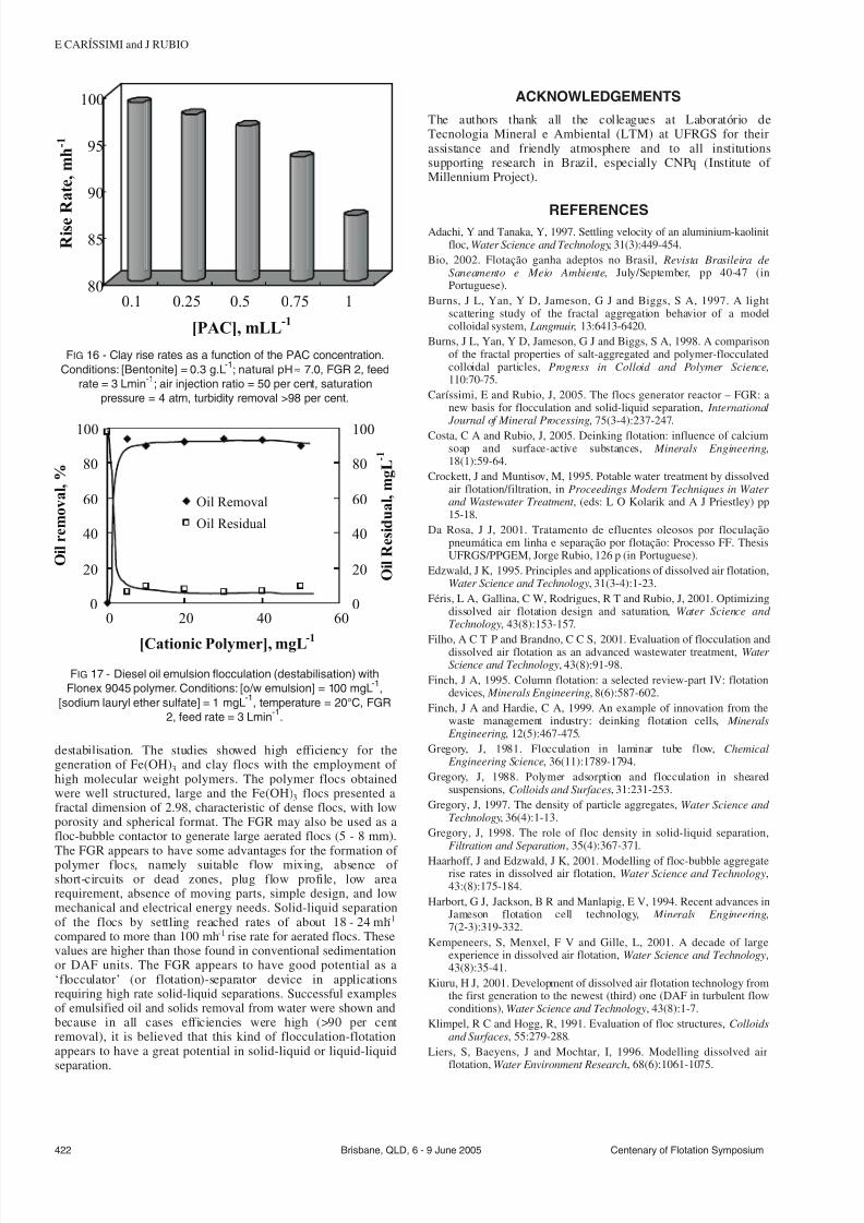
7232019 Advances in Particulates Aggregation-Flotation Separation
httpslidepdfcomreaderfulladvances-in-particulates-aggregation-flotation-separation 89
destabilisation The studies showed high efficiency for thegeneration of Fe(OH)3 and clay flocs with the employment of high molecular weight polymers The polymer flocs obtainedwere well structured large and the Fe(OH)3 flocs presented afractal dimension of 298 characteristic of dense flocs with lowporosity and spherical format The FGR may also be used as afloc-bubble contactor to generate large aerated flocs (5 - 8 mm)
The FGR appears to have some advantages for the formation of polymer flocs namely suitable flow mixing absence of short-circuits or dead zones plug flow profile low arearequirement absence of moving parts simple design and lowmechanical and electrical energy needs Solid-liquid separationof the flocs by settling reached rates of about 18 - 24 mh-1
compared to more than 100 mh-1 rise rate for aerated flocs Thesevalues are higher than those found in conventional sedimentationor DAF units The FGR appears to have good potential as alsquoflocculatorrsquo (or flotation)-separator device in applicationsrequiring high rate solid-liquid separations Successful examplesof emulsified oil and solids removal from water were shown andbecause in all cases efficiencies were high (gt90 per centremoval) it is believed that this kind of flocculation-flotationappears to have a great potential in solid-liquid or liquid-liquid
separation
ACKNOWLEDGEMENTS
The authors thank all the colleagues at Laboratoacuterio deTecnologia Mineral e Ambiental (LTM) at UFRGS for theirassistance and friendly atmosphere and to all institutionssupporting research in Brazil especially CNPq (Institute of Millennium Project)
REFERENCESAdachi Y and Tanaka Y 1997 Settling velocity of an aluminium-kaolinit
floc Water Science and Technology 31(3)449-454Bio 2002 Flotaccedilatildeo ganha adeptos no Brasil Revista Brasileira de
Saneamento e Meio Ambiente JulySeptember pp 40-47 (inPortuguese)
Burns J L Yan Y D Jameson G J and Biggs S A 1997 A lightscattering study of the fractal aggregation behavior of a modelcolloidal system Langmuir 136413-6420
Burns J L Yan Y D Jameson G J and Biggs S A 1998 A comparisonof the fractal properties of salt-aggregated and polymer-flocculatedcolloidal particles Progress in Colloid and Polymer Science11070-75
Cariacutessimi E and Rubio J 2005 The flocs generator reactor ndash FGR anew basis for flocculation and solid-liquid separation International Journal of Mineral Processing 75(3-4)237-247
Costa C A and Rubio J 2005 Deinking flotation influence of calciumsoap and surface-active substances Minerals Engineering18(1)59-64
Crockett J and Muntisov M 1995 Potable water treatment by dissolvedair flotationfiltration in Proceedings Modern Techniques in Water and Wastewater Treatment (eds L O Kolarik and A J Priestley) pp15-18
Da Rosa J J 2001 Tratamento de efluentes oleosos por floculaccedilatildeopneumaacutetica em linha e separaccedilatildeo por flotaccedilatildeo Processo FF ThesisUFRGSPPGEM Jorge Rubio 126 p (in Portuguese)
Edzwald J K 1995 Principles and applications of dissolved air flotationWater Science and Technology 31(3-4)1-23
Feacuteris L A Gallina C W Rodrigues R T and Rubio J 2001 Optimizingdissolved air flotation design and saturation Water Science and Technology 43(8)153-157
Filho A C T P and Brandno C C S 2001 Evaluation of flocculation anddissolved air flotation as an advanced wastewater treatment Water Science and Technology 43(8)91-98
Finch J A 1995 Column flotation a selected review-part IV flotationdevices Minerals Engineering 8(6)587-602
Finch J A and Hardie C A 1999 An example of innovation from thewaste management industry deinking flotation cells Minerals Engineering 12(5)467-475
Gregory J 1981 Flocculation in laminar tube flow Chemical Engineering Science 36(11)1789-1794
Gregory J 1988 Polymer adsorption and flocculation in shearedsuspensions Colloids and Surfaces 31231-253
Gregory J 1997 The density of particle aggregates Water Science and Technology 36(4)1-13
Gregory J 1998 The role of floc density in solid-liquid separationFiltration and Separation 35(4)367-371
Haarhoff J and Edzwald J K 2001 Modelling of floc-bubble aggregaterise rates in dissolved air flotation Water Science and Technology43(8)175-184
Harbort G J Jackson B R and Manlapig E V 1994 Recent advances inJameson flotation cell technology Minerals Engineering7(2-3)319-332
Kempeneers S Menxel F V and Gille L 2001 A decade of largeexperience in dissolved air flotation Water Science and Technology43(8)35-41
Kiuru H J 2001 Development of dissolved air flotation technology fromthe first generation to the newest (third) one (DAF in turbulent flowconditions) Water Science and Technology 43(8)1-7
Klimpel R C and Hogg R 1991 Evaluation of floc structures Colloidsand Surfaces 55279-288
Liers S Baeyens J and Mochtar I 1996 Modelling dissolved airflotation Water Environment Research 68(6)1061-1075
422 Brisbane QLD 6 - 9 June 2005 Centenary of Flotation Symposium
E CARIacuteSSIMI and J RUBIO
0
20
40
60
80
100
0 20 40 60
[Cationic Polymer] mgL-1
O i l r e m o v a l
0
20
40
60
80
100
O i l R e s i d u a l m g L - 1
Oil Removal
Oil Residual
FIG 17 - Diesel oil emulsion flocculation (destabilisation) with
Flonex 9045 polymer Conditions [ow emulsion] = 100 mgL-1
[sodium lauryl ether sulfate] = 1 mgL-1
temperature = 20degC FGR
2 feed rate = 3 Lmin-1
80
85
90
95
100
R i s e R a t e m h - 1
01 025 05 075 1
[PAC] mLL-1
FIG 16 - Clay rise rates as a function of the PAC concentration
Conditions [Bentonite] = 03 gL-1
natural pH asymp 70 FGR 2 feed
rate = 3 Lmin-1
air injection ratio = 50 per cent saturation
pressure = 4 atm turbidity removal gt98 per cent
7232019 Advances in Particulates Aggregation-Flotation Separation
httpslidepdfcomreaderfulladvances-in-particulates-aggregation-flotation-separation 99
Matis K A and Lazaridis N K 2002 Flotation techniques in watertechnology for metals recovery dispersed-air versus dissolved-airflotation J Min Metall A381-27
Matis K A 1995 Flotation Science and Engineering 584 p (MarcelDekker New York)
Matis K A Zouboulis A I Gallios G P Erwe T and Bloumlcher C 2004Application of flotation for the separation of metal-loaded zeolitesChemosphere 5565-72
Mavros P and Matis K A (eds) 1992 Innovations in Flotation
Technology (Kluwer Academic Publishers Dordrecht)Montgomery D C 1991 Design and Analysis of Experiments third
edition 649 p (John Wiley and Sons Inc Canada)Oslashdegaard H 2001 The use of dissolved air flotation in municipal
wastewater treatment Water Science and Technology 43(8)83-90Oliveira J C 2004 Tecnologia para despoluir o rio Pinheiros
Saneamento Ambiental 10868 (in Portuguese)Owen J J Morse D E Morse W O and Jovine R 1999 New
developments in flotation equipment for water treatment systems in Advances in Flotation Technology (eds B K Parekh and J D Miller)pp 381-389 (Society for Mining Metallurgy and Exploration Inc(SME) Littleton)
Palanuweck J and Coupland J N 2003 Effect of surfactant type on thestability of oil-in-water emulsions to dispersed phase crystallizationColloids and Surfaces A Physicochemical and Engineering Aspects223251-262
Parekh B K and Miller J D (eds) 1999 Advances in FlotationTechnology (Society for Mining Metallurgy and Exploration Inc(SME) Littleton)
Purchas D B 1977 SolidLiquid Separation Equipment Scale Up 584 p(Upland Press Ltd)
Reali M A P and Marchetto M 2001 High-rate dissolved air flotationfor water treatment Water Science and Technology 43(8)51-57
Rodrigues R T and Rubio J 2003 New basis for measuring the sizedistribution of bubbles Minerals Engineering 16757-765
Rosa J J and Rubio J 2005 The FF (flocculation-flotation) process Minerals Engineering 18(7)701-707
Rubio J 1998 Environmental applications of the flotation process in Effluent Treatment in the Mining Industry (eds S H Castro F Vergaraand M Sanchez) Chapter 8 pp 335-364 (University of Concepcioacuten-Chile Chile)
Rubio J 2003 Unconventional flocculation and flotation in ProceedingsFlotation and Flocculation From Fundamentals to ApplicationsStrategic Conference and Workshop Hawaii (eds J Ralston J Miller
and J Rubio) pp 17-32Rubio J Souza M L and Smith R W 2002 Overview of flotation as a
wastewater treatment technique Minerals Engineering 15139-155Rubio J Tessele F Porcile P A and Marinkovic E 2001 Flotacioacuten
como proceso de remocioacuten de contaminantes I Principios baacutesicosteacutecnicas y aplicaciones Minerales 56(242)9-18 (in Spanish)
Schofield T 2001 Dissolved air flotation in drinking water productionWater Science and Technology 43(8)9-18
Shannon W T and Buisson D H 1980 Dissolved air flotation in hotwater Water Research 14(7)759-765
Tang P Greenwood J and Raper A 2002 A model to describe thesettling behavior or fractal aggregates Journal of Colloid and Interface Science 247210-219
Voronin N N and Dibrov I A 1998 Classification of flotation processesin wastewater decontamination Journal of Environmental Engineering 124(5)469-472
Weber W J 1972 Physicochemical Processes for Water Quality Control640 p (Wiley-Interscience New York-USA)
Weir S and Moody G M 2003 The importance of flocculant choice withconsideration to mixing energy to achieve efficient solidliquidseparation Minerals Engineering 16(2)109-113
Zhou Z A Zhenghe Xu and Finch J A 1994 On the role of cavitationin particle collection during flotation ndash a critical review Minerals Engineering 7(9)1073-1084
Centenary of Flotation Symposium Brisbane QLD 6 - 9 June 2005 423
ADVANCES IN PARTICULATES AGGREGATION-FLOTATION SEPARATION