
Advances in Fiber Tier ˜ Enterprise & Data Center Testing · Advances in Fiber Tier ˜ Enterprise...
5
White Paper Advances in Fiber Tier 2 Enterprise & Data Center Testing As the volume of fibers deployed into enterprise increases significantly, fiber cabling advances like multi-fiber (MPO) connectors and interfaces between simplex, duplex, and MPOs have evolved to reduce space and speed installations. The importance of proper testing to effectively qualify and troubleshoot these more complex links has also increased due to higher data rates in both single mode and multimode fiber environments. These more stringent requirements create challenges to simplify testing for technicians, while also increasing testing efficiency and accuracy. Multimode deployments are even more challenging than single mode due to the higher test inaccuracies that occur due to optical launch conditions (proper filling of the fiber core during testing). As network speeds continue to increase, so does the importance of ensuring pristine end-face conditions. While inspection is not specifically covered in this application note, proper implementation of inspection and cleaning techniques for all connector end-faces plays an equally important role, and is a prerequisite for successful execution of all topics discussed in this document. Refer to IEC 61300-3-35, or http://www.viavisolutions.com/sites/default/files/technical-library-files/IEC-an-fit-tm-ae.pdf for more information. Test Improvement Challenges Today’s most significant test challenges for Tier 2 in enterprise and data center fiber deployments can be summarized as follows: 1. Assessing multimode fiber links accurately 2. Reducing test time for multi-fiber interconnects 3. Enabling Tier 2 testing by technicians of any skill level 4. Facilitating effective troubleshooting of MPO breakout cassettes Let’s look at each of these challenges in more detail.
Transcript of Advances in Fiber Tier ˜ Enterprise & Data Center Testing · Advances in Fiber Tier ˜ Enterprise...

White Paper
Advances in Fiber Tier 2 Enterprise & Data Center Testing
As the volume of fibers deployed into enterprise increases significantly, fiber cabling advances like multi-fiber (MPO) connectors and interfaces between simplex, duplex, and MPOs have evolved to reduce space and speed installations. The importance of proper testing to effectively qualify and troubleshoot these more complex links has also increased due to higher data rates in both single mode and multimode fiber environments.
These more stringent requirements create challenges to simplify testing for technicians, while also increasing testing efficiency and accuracy. Multimode deployments are even more challenging than single mode due to the higher test inaccuracies that occur due to optical launch conditions (proper filling of the fiber core during testing).
As network speeds continue to increase, so does the importance of ensuring pristine end-face conditions. While inspection is not specifically covered in this application note, proper implementation of inspection and cleaning techniques for all connector end-faces plays an equally important role, and is a prerequisite for successful execution of all topics discussed in this document. Refer to IEC 61300-3-35, or http://www.viavisolutions.com/sites/default/files/technical-library-files/IEC-an-fit-tm-ae.pdf for more information.
Test Improvement ChallengesToday’s most significant test challenges for Tier 2 in enterprise and data center fiber deployments can be summarized as follows:
1. Assessing multimode fiber links accurately
2. Reducing test time for multi-fiber interconnects
3. Enabling Tier 2 testing by technicians of any skill level
4. Facilitating effective troubleshooting of MPO breakout cassettes
Let’s look at each of these challenges in more detail.
2 Advances in Fiber Tier 2 Enterprise & Data Center Testing
1. Accurate assessment of multimode fiber links
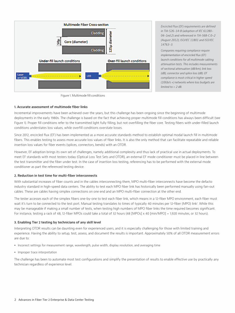
Incremental improvements have been achieved over the years, but this challenge has been ongoing since the beginning of multimode deployments in the early 1980s. The challenge is based on the fact that achieving proper multimode fill conditions has always been difficult (see Figure 1). Proper fill conditions refer to the transmitted light fully filling, but not overfilling the fiber core. Testing fibers with under-filled launch conditions understates loss values, while overfill conditions overstate losses.
Since 2012, encircled flux (EF) has been implemented as a more accurate standards method to establish optimal modal launch fill in multimode fibers. This enables testing to assess more accurate loss values of fiber links. It is also the only method that can facilitate repeatable and reliable insertion loss values for fiber events (splices, connectors, bends) with an OTDR.
However, EF adoption brings its own set of challenges, namely additional complexity and thus lack of practical use in actual deployments. To meet EF standards with most testers today (Optical Loss Test Sets and OTDR), an external EF mode conditioner must be placed in line between the test transmitter and the fiber under test. In the case of insertion loss testing, referencing has to be performed with the external mode conditioner as part the referenced testing device.
2. Reduction in test time for multi-fiber interconnects
With substantial increases of fiber counts and in the cables interconnecting them, MPO multi-fiber interconnects have become the defacto industry standard in high-speed data centers. The ability to test each MPO fiber link has historically been performed manually using fan-out cables. These are cables having simplex connections on one end and an MPO multi-fiber connection at the other end.
The tester accesses each of the simplex fibers one-by-one to test each fiber link, which means in a 12-fiber MPO environment, each fiber must wait it’s turn to be connected to the test port. Manual testing translates to times of typically 40 minutes per 12-fiber (MPO) link1. While this may be manageable if making a small number of tests, when testing high numbers of MPO fiber links the time required becomes significant. For instance, testing a rack of 48, 12-fiber MPOs could take a total of 32 hours (48 [MPOs] x 40 [min/MPO] = 1,920 minutes, or 32 hours).
3. Enabling Tier 2 testing by technicians of any skill level
Interpreting OTDR results can be daunting even for experienced users, and it is especially challenging for those with limited training and experience. Having the ability to setup, test, assess, and document the results is important. Approximately 50% of all OTDR measurement errors are due to:
Incorrect settings for measurement range, wavelength, pulse width, display resolution, and averaging time
Improper trace interpretation
The challenge has been to automate most test configurations and simplify the presentation of results to enable effective use by practically any technician regardless of experience level.
Figure 1. Multimode fill conditions
Encircled Flux (EF) requirements are defined in TIA-526−14-B (adoption of IEC 61280− 04−1ed.2) and referenced in TIA-568-C.0−2 (August 2012), ISO/IEC 11801 and ISO/IEC 14763−3.
Companies requiring compliance require implementation of encircled flux (EF) launch conditions for all multimode cabling attenuation tests. This includes measurements of sectional attenuation (dB/km), link loss (dB), connector and splice loss (dB). EF compliance is most critical in higher speed (10Gb/s +) networks where loss budgets are limited to < 2 dB.

3 Advances in Fiber Tier 2 Enterprise & Data Center Testing
4. Facilitating effective troubleshooting of MPO breakout cassettes
Simplex and duplex connections are still predominantly used on transmission and receiver equipment which requires a conversion from MPO to individual breakout simplex or duplex connectors. The most common method used today is to employ an MPO breakout cassette. In this setup, a “cassette” is equipped with a multi-fiber MPO-style connector on one side, while on the other side of the cassette simplex connectors are placed with individual fibers connecting them inside the cassette with a predefined polarity order.
These cassettes can be problematic due to 1) the number of connectors in each cassette, and 2) the short length of the fiber inside the cassette between optical connections. In order to isolate an issue in the cassette to a specific connector, a higher-resolution OTDR with a very short attenuation dead zone (~ 1meter) is needed.
Solving Challenges Individually and TogetherThis document reviews how VIAVI Solutions has addressed each of these challenges to improve fiber deployments. It also introduces our latest test solutions integrating these advances to provide even more value through increasing accuracies and efficiencies. This has never been more critical than with today’s high-speed data center fiber deployments.
1. Accurate assessment of multimode fiber links
Today VIAVI offers these improvements with two options:
a. An EF mode conditioner device can be inserted during testing between the OTDR (or other test source) and the fiber under test. This device conditions the launch signal for EF compliance before the test signal enters the fiber under test (see Figure 6 later in this document). When paired with an external mode conditioner, the T-BERD/MTS 2000 or 4000 allows any 50um multimode test source to provide testing results that comply with the new EF standards.
b. The EVO-A modules from VIAVI offer integrated EF-compliance for T-BERD/MTS 8000 (v2) and 6000A v2 platforms. This eliminates the need for an external EF mode conditioner, which simplifies implementation by test technicians and ensures improvements in loss accuracies that EF compliance provides (see Figure 7 later in this document).
2. Reduction in test time for multi-fiber interconnects
VIAVI now offers 1x12 fiber MPO optical switches as accessories to its enterprise testing portfolio. The switch is placed inline between the OTDR and the MPO test access point for the link. More specifically, the OTDR module is connected to the simplex side of the switch via a 50um patch cord. The MPO side of the switch is connected to the MPO test access port via an MPO to MPO 10 meter patch cord. The optical switch is easily controlled by the OTDR via micro-USB connection.
Actual test results show that implementation of an optical switch in-line can cut testing time by more than half. In the case of testing a 12-fiber MPO link in 40 minutes, the switch reduced the test time to under 20 minutes. This provides significant time savings, especially when testing high volumes of MPOs. Another benefit is less wear on test cords by a factor of 12 (assuming a 12-fiber MPO) as it eliminates repeat connections during testing.
3. Enable Tier 2 testing by technicians of any skill level
Enterprise Smart Link Mapper (Enterprise-SLM) is the newest addition to the VIAVI SLM Smart test family. It is specifically designed for enterprise and data center applications. It converts OTDR results into a simple link schematic. The health of the link is assessed with a pass/fail indication, with any fails highlighted and clearly explained as to likely cause and measurement value. Enterprise-SLM virtually eliminates the need to view an OTDR trace. Pre-defined setup configurations can be loaded in advanced by management or engineering and instructions provided to field technicians for use scenarios. This drives testing consistency between technicians and reduces the level of training required even further.
Figure 2. MPO Break-out cassette
Figure 3. OTDR Optical Switch Interface
Figure 4. Enterprise Smart Link Mapper Interface

4 Advances in Fiber Tier 2 Enterprise & Data Center Testing
Figure 5. Resolution comparison standard-res OTDR to EVO-A
Figure 6. MPO Link Test Setup for faster testing Figure 7. Test setup for Hi-Res link testing with breakout cassettes
4. Facilitating effective troubleshooting of MPO breakout cassettes
The fiber inside an MPO breakout cassette is less than one meter in length. Conventional OTDRs do not have the dead zone performance required to test both connectors within the cassette. The VIAVI EVO-A high-resolution OTDR is equipped with the performance needed to troubleshoot and verify MPO breakout cassettes. The EVO-A modules operate with T-BERD/MTS 6000A v2 and 8000 (v2) series mainframes.
Improving enterprise and data center test efficiencies While each of the solutions listed above individually provide key improvements in enterprise and data center testing, several of these solutions can be combined to sustain even more significant savings in time, accuracy and performance.
For basic testing of an MPO data link, the figure below illustrates a VIAVI T-BERD/MTS 2000 using an in-line EF mode conditioner and integrated external optical switch to test MPO links faster and more accurately. Launch and receive fibers are employed just before and after the link under test to enable the MPO connections to also be evaluated.
In a more advanced integration example illustrated below, the VIAVI T-BERD/MTS 6000A V2 equipped with an EF compliant EVO-A OTDR module is used with the MPO optical switch. Fan-out launch and receive fibers are used on both ends of the link. This combination enables both the link and the two connections inside the MPO breakout cassette to be tested. The higher resolution and better dead zone performance as described earlier, combined with the efficiency improvements in the optical switch, provide a best-in-class solution for even the most demanding high-speed data center applications.
Figure 8. Hi-Res link test Translation to Traditional OTDR View

© 2017 VIAVI Solutions Inc.Product specifications and descriptions in this document are subject to change without notice. fibertier2-wp-fit-nse-ae30186031 901 1017
Contact Us +1 844 GO VIAVI (+1 844 468 4284)
To reach the VIAVI office nearest you, visit viavisolutions.com/contacts.
viavisolutions.com
SummaryThe advances covered in this document bring significant procedural improvements allowing more effective testing of high-speed data center environments. When selectively combined, these tools can result in even higher productivity, and in some cases lower the training hurdle to enable more widespread usability.
VIAVI Solutions continues to lead industry innovation in providing faster, easier, and smarter solutions for all levels of enterprise and data center applications.
References1ManuallyTesting MPOs – OTDR Test time estimate
a. Initial OTDR Prep (inspect/clean OTDR output, test access connector and install): 4 minutes
b. Prep 1st fiber (inspect/clean test cord and fanout access connector & connect: 2 minutes
c. Run test at 20 sec averaging for 850 and 1300nm: 1 minute
d. Repeat b and c for the remaining 11 fibers on the 12-fiber ribbon: 3 x 11 = 33 min
Calculation: a + (b+c) + d
4 + (2+1) + 33 = 40 min total MPO test time
Also see notes below:
NOTE:Below is possible link to an article with data on increases in fiber counts and speeds. You may want to pull a quote or statistics from this article (or you may have some statistics of your own).http://www.datacenterjournal.com/high-fiber-counts-facilitate-data-center-growth/
Impact on Structured Cabling
Traditional structured cabling deployments in the data center are based on infrastructure designs using pre-terminated MTP assemblies ranging from 12 to 144 fibers. To support the growing bandwidth needs as well as changing technologies and architectures, fiber-count requirements are also increasing, with spaces in the data center requiring connectivity to support demands of up to 288 fibers in a single run—and even fiber counts of 576 fibers in high-density areas.
When we look at the above examples, we can see the additional value of using Enterprise-SLM to translate the measurement data into a clear and concise assessment of the link condition.
Alarms
Distance m Fault Detected
121.35m Connector Loss too high
Figure 9. Hi-res link test with MPO cassettes as viewed in Enterprise SLM