
Advanced Perspective Techniques
76
12/7/09 9:27 PM handprint : advanced perspective techniques Page 1 of 76 http://www.handprint.com/HP/WCL/perspect5.html advanced perspective techniques The previous pages developed the methods of linear perspective using the cube (or other rectangular objects) as the primary form. This was convenient because the edges and right angles of these objects simplify perspective constructions. When tackling the perspective of complex or irregular shapes, the basic strategy is to fit these shapes inside a regular geometric figure or solid, like a valentine inside an envelope or a vase inside a box, then use this rectangular solid to "mail" the form into perspective space. This page gives several examples of how to do this for plane figures and solid forms . Next, I provide a tutorial on projecting a building, which is just another type of complex volume, from architectural elevations and plan . The same methods apply to any object for which elevations and plan are available. The methods of paraline perspective , based on the geometry of parallel projection, were developed in the 18th century (at the rise of the Industrial Revolution) for a variety of engineering and manufacturing applications. I present a few of the common forms and discuss how they relate to the perspective of central projection. I conclude with a brief discussion of curvilinear perspectives , a modern and dogmatic answer to the "distortions" in traditional linear perspective. I show how to make a basic curvilinear template and explain why the usual justifications for curvilinear perspective are fallacious. perspective of complex plane figures technique perspective of complex plane figures perspective of complex solid forms buildings from blueprints or plans paraline perspectives curvilinear perspectives
Transcript of Advanced Perspective Techniques

12/7/09 9:27 PMhandprint : advanced perspective techniques
Page 1 of 76http://www.handprint.com/HP/WCL/perspect5.html
advanced perspective techniques
The previous pages developed
the methods of linear perspective using thecube (or other rectangular objects) as theprimary form. This was convenient becausethe edges and right angles of these objectssimplify perspective constructions.
When tackling the perspective of complex orirregular shapes, the basic strategy is to fitthese shapes inside a regular geometric figureor solid, like a valentine inside an envelope ora vase inside a box, then use this rectangularsolid to "mail" the form into perspectivespace. This page gives several examples ofhow to do this for plane figures and solidforms.
Next, I provide a tutorial on projecting abuilding, which is just another type ofcomplex volume, from architecturalelevations and plan. The same methodsapply to any object for which elevations andplan are available.
The methods of paraline perspective, basedon the geometry of parallel projection, weredeveloped in the 18th century (at the rise ofthe Industrial Revolution) for a variety ofengineering and manufacturing applications. Ipresent a few of the common forms anddiscuss how they relate to the perspective ofcentral projection.
I conclude with a brief discussion ofcurvilinear perspectives, a modern anddogmatic answer to the "distortions" intraditional linear perspective. I show how tomake a basic curvilinear template and explainwhy the usual justifications for curvilinearperspective are fallacious.
perspective of complex plane
figures
technique
perspective of
complex plane figures
perspective ofcomplex solid forms
buildings fromblueprints or plans
paraline perspectives
curvilinear perspectives

12/7/09 9:27 PMhandprint : advanced perspective techniques
Page 2 of 76http://www.handprint.com/HP/WCL/perspect5.html
One of the most common
perspective problems is rendering inperspective a curved or irregular figure that isnot a composite of squares or rectangles. Themost common example is a circle inperspective, as the rim or contour of a disk,drinking glass, bowl or cylinder.
The solution in each case is the same: to usethe square (or a metric grid within a square)as the projection framework or projectionsquare. The rationale is that it is that it issimple to project a square in perspective, andonce this is done the square or grid can beused to transfer descriptive points from aplan or elevation view of the figure.
The general procedure is: (1) enclose thecomplex figure within a regular rectangularform (square or rectangle); (2) divide therectangular area with a regular grid and/or amajor diagonal; (3) identify the pointintersections of the figure with the sides ofthe square, the grid or the diagonal; and (4)transfer these landmark points into the imageplane, where they are used to reconstruct thefigure image.
Projecting A Circle. Let's start with thesimplest case, projecting a circle inperspective. I know of several differentmethods to do this, but provide here two thatare among the easiest and most effective.
Circle Without a Plan. There is a very usefulmethod to construct the circle entirely fromthe geometry of the square. No plan isrequired, because the points are definedentirely within the image plane; the diagram(below) shows a plan view only to clarify howthe method works.

12/7/09 9:27 PMhandprint : advanced perspective techniques
Page 3 of 76http://www.handprint.com/HP/WCL/perspect5.html
projecting a circle without a plan
Begin with any square established inperspective at the appropriate scale, location,and angle of view. The circle defines a plane,and the vanishing line for this plane must beavailable as the principal point (orthogonalvanishing point) and diagonal vanishing point,or the controlling vanishing point(s) andmeasure points. A diagonal vanishing point ormeasure point is only necessary to define thesquare in depth, but the principal point orprimary vanishing point of recession isrequired. Then: 1. Construct the full diagonals, ab andmatching.
2. From the full diagonal intersection (centerof the square), construct the half transversalto c and the half orthogonal from theprincipal point through d. Mark the four

12/7/09 9:27 PMhandprint : advanced perspective techniques
Page 4 of 76http://www.handprint.com/HP/WCL/perspect5.html
intersections with the sides of the square, cand d and the points opposite (black).
3. Construct two quarter diagonals, c to dand matching on the opposite side. Constructthe two quarter orthogonals from the principalpoint through the intersection e and its twin.
4. From the intersections of the quarterorthogonals with the full diagonals, such as e,construct the quarter transversals. Theprojection square is now divided into sixteensmaller squares.
5. Construct the two rectangular diagonalsfrom each corner of the square to theintersection of the nearest quarter line withthe opposite side of the square: that is, a tog opposite, h to f opposite, and similarly forthe other six rectangular diagonals.
6. Near each corner, mark the intersection ofthe rectangular diagonals from that cornerwith the nearest quarter orthogonal orquarter transversal: that is, x and y forcorner a, and similarly for the other threecorners (black).
7. Finally, join the twelve points, freehand orwith a French curve, to produce the circle.
This method is "nearly accurate", becausepoints x and y stand slightly outside a perfectcircle, as is visible in the diagram. Howeverthis is inconsequential when working small orwith very foreshortened figures; or the circlecan be drawn to miss slightly the pair ofcorner guide points.
Circle With a Plan. Using a plan results in aslightly more accurate set of guide points,and additionally requires fewer guidelines todefine. The diagram below shows theprocedure.

12/7/09 9:27 PMhandprint : advanced perspective techniques
Page 5 of 76http://www.handprint.com/HP/WCL/perspect5.html
projecting a circle with a plan
Begin with any square established inperspective at the appropriate scale, location,and angle of view. The circle defines a plane,and the vanishing line for this plane must beavailable, either as the principal point anddiagonal vanishing point or controllingvanishing point(s). A diagonal vanishing pointis only necessary to define the square indepth. Then:
1. In the plan (projection square) and imagesquare, define the full diagonals, ab andmatching.
2. In the plan and image square, divide thesquare half by a perpendicular line (plan) ororthogonal to the principal point (image)through the intersection of the full diagonals.Divide again by a perpendicular horizontal line(plan) or transversal (image). Mark the four

12/7/09 9:27 PMhandprint : advanced perspective techniques
Page 6 of 76http://www.handprint.com/HP/WCL/perspect5.html
points where these lines intersect the square,c and d and the points opposite (black).
3. Construct two quarter diagonals, c to dand matching on the opposite side. Constructthe two quarter orthogonals from the principalpoint through the intersection e and its twin.
4. From the intersection of quarter and fulldiagonals (e and matching on the oppositeside), construct a horizontal line to the side ofthe square. This intersects the circle at f andmatching on the opposite side.
5. Mark the intersection of the circle with thefull diagonal, at g and on the opposite side.
6. With eight vertical lines, carry the eightpoints d, b, a, g, f, e and matching up to theprojection line, then project to the principalpoint with orthogonals. Using the intersectionsof orthogonals with the image squarediagonals, identify the points within the imagecircle; then use orthogonals and transversalsto reproduce matching points at othercorners.
7. Finally, join the twelve points, freehand orwith a French curve, to produce the circle.
Note that a and b are already defined in theimage square; d can be located with anorthogonal from the principal point throughtthe image diagonal intersection; and theprojection line from e (and the matchingpoint) can be found in the image square by atransversal from the diagonal intersection ofthe projection line from f, through the circleto the opposite diagonal. Consequently onlyfour projection lines are necessary — from fand g and the matching points on the otherside — as shown by the pink lines in thediagram.
Circle with Trigonometric Ratios. Finally,an even more accurate method for projectinga circle was first used by Paolo Uccello, asdescribed below). It is based on a closepartitioning of the circle's circumference into32 equal segments, which however makes theprojection task more efficient.

12/7/09 9:27 PMhandprint : advanced perspective techniques
Page 7 of 76http://www.handprint.com/HP/WCL/perspect5.html
uccello's method of projecting the circle
1. Divide the circle plan with 16 equallyspaced "spokes"; these are found by dividingthe circle into quarters by a horizontal andvertical line intersecting at the circle center,then bisecting the two upper 90° angles 3times.
2. Carry the 17 intersection points to theprojection line, and project by orthogonals tothe principal point.
3. Mark the intersection of each orthogonalwith a major diagonal of the image square(magenta points). From these points construct15 transversals across the image square.
4. Identify the point intersections of eachtransversal with the matching orthogonals on

12/7/09 9:27 PMhandprint : advanced perspective techniques
Page 8 of 76http://www.handprint.com/HP/WCL/perspect5.html
both sides of the square, and the two pointintersections of the central orthogonal withthe front and back of the square. Connectthese 32 points to form the circle.
The elegance of the original plan bisection isthat each projection point stands for both ahorizontal and vertical location of thecircumference points; the artist simply locatesthe intersection of the projection orthogonalswith a major diagonal of the image squareand the transversals duplicate these locationson opposite sides of the circle, creating the 32points that define the circumference.
The location of these points along the width ofa projection line, of unit length 1.0, is derivedfrom the cosine of the angle of each "spoke"to the direction of view. The sequence istabulated below for reference.
unit ratio locationsfor 16 spoke division of circle
circumference(0.5 = midpoint of unit distance)
spoke no. angle to DOV proportion ofunit dimension
1 -90° 0.000
2 -78.75° 0.009
3 -67.5° 0.038
4 -56.25° 0.084
5 -45° 0.146
6 -33.75° 0.222
7 -22.5° 0.309
8 -11.25° 0.403
9 0° 0.500
10 11.25° 0.597
11 22.5° 0.691
12 33.75° 0.778
13 45° 0.854
14 56.25° 0.916

12/7/09 9:27 PMhandprint : advanced perspective techniques
Page 9 of 76http://www.handprint.com/HP/WCL/perspect5.html
15 67.5° 0.962
16 78.75° 0.991
17 (=1) 90° 1.000
To scale this series, just multiply by the unitlength and measure from one end of thedimension. Thus, to project a circle from aprojection line that is 20 cm wide, multiply by20: then the -45° angle (spoke #5) is located2.9 cm from the dimension end.
Ellipse Construction. Now an importantconstant in perspective construction is that:
A circle in physical space always appears asan ellipse on the image plane, except when itis viewed edge on.
This means we can circumvent the wholerigamarole of partitioning a plan andprojecting it into perspective space: let's justconstruct the ellipse directly on the image!
Every ellipse can be described by its heightand width dimensions, known as its majoraxis (widest dimension) and minor axis(perpendicular to the major axis). This leadsto two simple methods for ellipse constructionand also a calculation to estimate theforeshortening of a circle. The diagram (right) shows how to constructan ellipse from fixed height and widthdimensions. In the first method (A), theheight and width define a rectangle, which isthen divided into equal quadrants by twolines. Then one interior horizontal linesegment and one exterior vertical linesegment are divided into proportionatelyequal parts, creating proportionately spacedpoints. (The points do not have to be equallyspaced, only equal in their proportionalspacing on the two lines.) Lines are drawnfrom the two midline points, a and b, throughthe respective points, as shown. Theintersection of matching lines defines a pointon the ellipse in one quadrant. The landmarkpoints are joined by a freehand curve orsegments of a French curve, then traced or

12/7/09 9:27 PMhandprint : advanced perspective techniques
Page 10 of 76http://www.handprint.com/HP/WCL/perspect5.html
copied into the other three quadrants.
The alternative and more efficient trammelmethod (B) is to define the ellipse rectangle,then transfer the length of the major andminor axes, aligned at one end, to a strip ofcardboard or heavy paper (diagram, right).Because the major and minor axes areunequal in length, there is an intervalbetween their end points at the other end(magenta line). These end points are alignedwith the minor and major axes of the ellipserectangle, and the circumference of the ellipsemarked off from the aligned end points at theother end of the card. This method is quick,although it becomes much less accurate asthe major and minor axes become equal (theellipse approaches a circular shape).
The third method (C) uses two concentriccircles, centered on point a; the two circlesare divided into quarters by perpendicularlines defining the major and minor axes of theellipse. An arbitrary number of lines aredrawn radially through both circles from pointa, creating pairs of points at the intersectionof the line with the inner and outer circles.Then lines are extended from these points,parallel with either the major or minor axes ofthe ellipse; their intersections define points onthe ellipse in one quadrant. An advantage ofthis method is that, by extending the"spokes" and the horizontal and verticalconstruction lines completely across the largercircle, the entire circumference can beidentified.
However, there is a problem. The circleconstruction diagrams above show that thecenter of the ellipse is not coincident with thecenter of the image square (the intersectionof the image diagonals), because recessioncauses the back half of the square to appearsomewhat smaller than the front half. Thus,the black cross identifying the center of theellipse is not located at the diagonal butsomewhat below (in front of) it.
This is the same difficulty that produces thevisual discrepancy between the visible
three methods forconstructing an ellipse of
fixed height and width

12/7/09 9:27 PMhandprint : advanced perspective techniques
Page 11 of 76http://www.handprint.com/HP/WCL/perspect5.html
circumference of a sphere (equal to theimage width of the major axis of the ellipse)and the visual angle of its diameter (equal tothe image width of the perspective squareacross its center). This problem is examinedin the section on projecting a sphere.Unfortunately, there is no simple way to scalethe width of the ellipse, other than making ascale drawing in plan, as the major axis is notcoincident with the midline transversal of thesquare, and the points where the ellipsetouches the square envelope are typically noton the major axis of the ellipse. But forperspective circles within a 20° circle of view,the discrepancy is so tiny that it can beignored.
This is a principal reason why architectstraditionally used ellipse templates and nowrely on computer drafting programs. Thetemplates contain a very large number ofellipse cutouts, each slightly larger than thelast, all scaled to a standard angle of viewonto the plane surface containing the circle.The artist simply chooses the template anglethat corresponds best to the proportions ofthe major and minor axes of the ellipserequired, then chooses the cutout that isclosest to the right image size.
The method for estimating the foreshorteningof a circle (the ellipse template angle) derivesfrom the trigonometric tangent within thecircle of view geometry:
Given a perspective square located near themedian line, draw the vertical line A from afront corner, and the horizontal line B fromthe opposite back corner; these lines intersectto form a right triangle. Using a ruler,measure the lengths of A and B and find thearctangent of their ratio. This is the angle of

12/7/09 9:27 PMhandprint : advanced perspective techniques
Page 12 of 76http://www.handprint.com/HP/WCL/perspect5.html
view onto the plane surface of the square atpoint x. This angle is used to identify themost suitable ellipse template.
In the illustration (counting in pixels), A =101 and B = 187, so the angle at x isapproximately the arctangent of 101/187, or28.4°. The formulas quoted in the section ondistance & size calculations allow you to usethis angle to infer the radius of the circle ofview that contains the square, and the objectdistance (X) of the center of the square fromthe viewpoint. For ellipses turned at an angledue to perspective distortion (see below), theellipse should be enclosed by a rectangletilted to the same angle; the tangent is foundfrom the height to width ratio.
Architects do not bother with any of this:they just try one or another template untilthey visually discover the best match in angleand size.
Photoshop note: Because a circle is an ellipsewhose major and minor axes are equal, anyellipse is just a circle image compressed alongone dimension. The Ellipse Marquee Tool canbe used to approximately define the ellipseoutline, and once this is colored in it can beadjusted to an exact fit by horizontal and/orvertical compression with the Free Transformtool.
Perspective Distortions (Reprise). Itshould not be surprising, if perspective"distortions" are in fact accurateperspective images and the circleconstruction methods create accurate imagecircles, that constructed circles will displayperspective distortions. So we have to reprisethe issue of distortions and how to deal withthem.
The example below is an extreme case, but ifyou compare it to the appearance ofspherical forms similarly displaced from thedirection of view, you will see it is no worsethan expected.

12/7/09 9:27 PMhandprint : advanced perspective techniques
Page 13 of 76http://www.handprint.com/HP/WCL/perspect5.html
perspective distortion in a 1PPconstructed circle
This is not just an artifact of the 1PPperspective: if we use a 2PP geometry theshape of the square containing the circle isimproved noticeably, but the circle is stillstrongly tilted. (The reduction in elongationand size is due to the fact that the imagesquare is closer to the principal point dvp andto the horizon line.)
perspective distortion in a 2PPconstructed circle
Some perspective tutorials advocate theradical solution of drawing an image circle inall situations as an ellipse with major axisparallel to the horizon line. Robert W. Gill, inan otherwise sensible perspective tutorial,claims that the normal perspective distortions

12/7/09 9:27 PMhandprint : advanced perspective techniques
Page 14 of 76http://www.handprint.com/HP/WCL/perspect5.html
of circles "are contrary to the laws ofperspective" — which is flatly incorrect. Theproblem is that perspective distortions aresometimes contrary to a pleasing image.
"Pleasing" is a practical rather thangeometrical issue, so the practical question is(for example) how an ellipse, with major axisparallel to the horizon line, can be fitted intothe geometrically correct 2PP image squareshown above. This is only possible if theellipse does not touch the square on one ortwo sides at the same time that the ellipse isgrossly flattened. Gill evades this difficulty bystanding the columns in his illustrations flaton the ground plane: but most architecturalcolumns rest on a square base or plinth, orare surrounded by square tiled floors, so theproportions and shape of the cylindricalcolumn and square base must correspond. Toaccommodate an acceptably rounded ellipseshape that touches the four sides of an imagesquare base, the perspective shape of thesquare base must also be "adjusted" byreducing its visual width. But now the columnand base are no longer in scale to thearchitectural elements around or behindthem, so these too must be adjusted ...
In effect, all these adjustments areincremental steps toward shifting the diagonalvanishing points, and with them the 2PPvanishing points, farther apart. So theappropriate solution for this problem is theclassical remedy for perspective distortions:reduce the circle of view contained withinthe image format or (equivalently) increasethe distance between the principal point anddiagonal vanishing points, or (equivalently)increase the object distance in perspectivespace.
If you are using an ellipse template, themajor axis of the ellipse should be alignedeither with a line to the opposite diagonalvanishing point (in 1PP) or at a slightly lesstilted angle than a line to the oppositevanishing point (in 2PP). I find an arc drawnfrom the opposite vanishing point, from thecenter of the ellipse to the horizon line,

12/7/09 9:27 PMhandprint : advanced perspective techniques
Page 15 of 76http://www.handprint.com/HP/WCL/perspect5.html
reasonably locates the direction in which theminor axis should be oriented.
Projecting Complex Plane Figures. A widerange of more complex plane figures can behandled by the square or rectangularprojection, and the method of distance pointprojection is the foundation method in thesecases.
However, the distance point procedure ofdrawing arcs to identify the diagonalprojections for every point in the figurequickly becomes cluttered, or requires a largeworking area. The more compact solution isto use the diagonal contained within theprojection square as the depth projectionmechanism, and project everything from theplan using only orthogonals to the principalpoint (or, for 2PP or 3PP drawings, theappropriate two measure points).
projecting a pentagonal plan intoperspective space
The method of diagonal depth projectionor rabattement is elegant and simple: draw a

12/7/09 9:27 PMhandprint : advanced perspective techniques
Page 16 of 76http://www.handprint.com/HP/WCL/perspect5.html
square around the form you want to project;draw a diagonal across this boundary;establish the diagonal twin for all key points;carry each point and its diagonal twin forwardto the measure bar; project the points fromthe measure bar into a square in perspectivespace with a diagonal carried to the diagonalvanishing point (dvp); establish the keypoints in perspective by construction.
In the example above, we want to project theplan of an irregular pentagon intoperspective. We first scale and rotate theplan, as described below, to the correctorientation and dimensions. Then we encloseit in a square, and draw a diagonal throughthe square. (Note that we don't have toexactly center the form within the square,and in fact it is the diagonal, and not theenclosing square, is the essential componentof the method. However, it is handy to putrequired points on the sides of the square, ifpossible, to eliminate one or more of theprojecting orthogonals.)
For each key point needed to construct theform, we first carry a horizontal line over tothe diagonal, then two vertical lines, from (1)the original point and (2) its intersection withthe diagonal line, up to the projection line.Thus, starting with point a, we carry ahorizontal to the diagonal at x, then verticalsfrom a and x to the projection line.
From the projection line, we project all thepoints back to the principal point (pp). Wealso project to pp the width of the square.Then, using the diagonal vanishing point, weconstruct the image square and, within thesquare its major diagonal.
Finally, for every point intersection with theplan diagonal, we construct a transversalfrom its intersection with the image diagonal.Thus the orthogonal for the plan diagonalpoint x intersects the image diagonal at pointx', which gives us the recession. Atransversal from x' intersects the orthogonalfrom a at the perspective location of point a'.The same is be repeated for each key point,

12/7/09 9:27 PMhandprint : advanced perspective techniques
Page 17 of 76http://www.handprint.com/HP/WCL/perspect5.html
except that orthogonals from points on thefront or back of the square (such as b)require no transversal, and points on thesides of the square (such as c) require noseparate orthogonal.
Provided that the vanishing points have beenaccurately rotated in relation to the 90°circle of view (the principal point and dvp's),these procedures work exactly the same in2PP, and the 2PP vanishing points are not atall required to project the figure inperspective. In fact, any number of forms canbe projected into the same perspective spaceusing the same diagonal depth method ofprojection, and their vanishing lines relativeto each other will harmonize exactly.
Finally, and most usefully, once a plane figurehas been projected into perspective space, aline extended from any of its sides to thevanishing line for the plane that contains it(e.g., the horizon line for figures in theground plane) identifies the vanishing pointfor that side and all physical lines parallel toit (diagram, above).

12/7/09 9:27 PMhandprint : advanced perspective techniques
Page 18 of 76http://www.handprint.com/HP/WCL/perspect5.html
projecting a street map into perspectivespace
North Tribeca historic district, from New York HistoricalSociety map
For example, in the irregular streetalignments typical of many premodern cityplans, a detailed street map of the area canbe projected onto the ground plan, and thisimage street layout used to define the 2PPvanishing points for the horizontals of thevarious buildings (pink lines, above).
Alternately, a metric grid can be projectedonto the image plane at the appropriatespacing and perspective depth (blue lines,

12/7/09 9:27 PMhandprint : advanced perspective techniques
Page 19 of 76http://www.handprint.com/HP/WCL/perspect5.html
above), and the map copied into the gridsquare by square, with diagonal depthprojection used to trace out the contours orlocations of difficult problems, such as thetraffic loop in the right foreground.
perspective of complex solid
forms
The strategy for projectingcomplex solids is essentially the threedimensional extension of the strategy forprojecting two dimensional figures. Thecomplex form is enclosed in or reduced tocubes or rectangles, and/or the grids ordiagonals they define, and the object isreconstructed from the landmark pointsdefined. I think most artists remember theirastonishment on first encountering the "wireframe" perspective drawing of a chalice byPaolo Uccello (right). In this case the complexconstruction was achieved by the painstakingaccumulation of simple perspective tasks, andin tribute I summarize them here:
1. The plan of a square for the base of thecup was constructed in perspective space.From the ellipse ratios evident at the topand bottom of the chalice, I find that Uccelloused a distance point (viewing distance) ofapproximately 8 times the height of the cup(e.g., the chalice is contained within a 7.2°circle of view). Thus, if the drawing is actualsize (29 cm high), the viewing distance wouldbe about 2.3 meters; and the base of the cupabout 58 cm below eye level.
2. Separately, the plan of a circle wasbisected, then quartered, and then eachsegment bisected again three times, resultingin 32 equal divisions of a circle.
3. The intersection points were brought byvertical lines to the projection line, thenprojected by orthogonals into the plan of asquare in perspective space. Note that thebisection method has produced intersectionpoints that are mirror symmetrical both
perspective drawing of achalice
Piero Uccello (c.1450)

12/7/09 9:27 PMhandprint : advanced perspective techniques
Page 20 of 76http://www.handprint.com/HP/WCL/perspect5.html
points that are mirror symmetrical bothhorizontally and vertically, so all that isrequired to reconstruct the square is theintersection of each orthogonal with thediagonals of the square (see diagram,above).
4. This square projection was repeated oversixty times, each time at a slightly differentscale and vertical location, to form theprincipal circumferences of the cup. Thevertical spacing of the squares wasaccomplished with an elevation drawing of thecup, or equivalently by physicalmeasurement; and the horizontal spacing bymeasurement.
5. The landmark points were connectedhorizontally to define the circumferenceedges, and vertically to the matching pointsin the circles above and below to define thecup surface.
Small misalignments and changes in lineweight suggest the finished cup drawing wasassembled from two or three componentdrawings; this implies that the drawing wehave was transferred, by pin pricks, fromother drawings, or is a scaled down version ofdrawings done in a larger format foraccuracy. The whole project must have takenweeks to complete.
In that context, it is interesting to hearGiorgio Vasari's comments on Uccello'sconsuming perspective studies:
"Paolo Uccello would have been the mostgracious and fanciful genius that was everdevoted to the art of painting, from Giotto'sday to our own, if he had labored as much atfigures and animals as he labored and losttime over the details of perspective; foralthough these are ingenious and beautiful,yet if a man pursues them beyond measurehe does nothing but waste his time, exhaustshis powers, fills his mind with difficulties, andoften transforms its fertility and readinessinto sterility and constraint, and renders hismanner, by attending more to these details

12/7/09 9:27 PMhandprint : advanced perspective techniques
Page 21 of 76http://www.handprint.com/HP/WCL/perspect5.html
than to figures, dry and angular, which allcomes from a wish to examine things toominutely; not to mention that he very oftenbecomes solitary, eccentric, melancholy andpoor, as did Paolo Uccello. This man,endowed by nature with a penetrating andsubtle mind, knew no other delight than toinvestigate certain difficult, nay impossibleproblems of perspective, which, although theywere fanciful and beautiful, yet hindered himso greatly in the painting of figures, that theolder he grew the worse he did them. ... Forthe sake of these investigations he kepthimself in seclusion and almost a hermit,having little intercourse with anyone, andstaying weeks and months in his housewithout showing himself." [Lives of thePainters, Sculptors and Architects, 1550;"Paolo Uccello, Painter of Florence"]
A cautionary word across the centures for themany modern perspective dabblers, includingdigital rendering engineers, who spend daysor weeks on a single texture map orillumination model. (Those solitarymelancholics who spend months porting it allonto an obscure web site, well ... they areexempt from caution.)
Projecting a Sphere. The sphere and itsrelated geometrical forms the cone andcylinder present a subtle difficulty. On the onehand, they are all circular in cross section andtherefore, in most cases, can be representedby an elliptical outline along the front edge orcircumference. On the other hand, they aresolids rather than plane figures, whichproduces specific problems of image scale andforeshortening.
Sphere Image Scale. The scaling problem isthat a sphere relatively close to the viewpointpresents a visual angle that is larger than thevisual angle of its physical diameter. That is,using a measure bar or unit distance toproject the diameter of a sphere inperspective space will underestimate itsactual apparent size. The diagram shows why:the angle of view to the limb of the sphere isin front of the diameter, at its visible

12/7/09 9:27 PMhandprint : advanced perspective techniques
Page 22 of 76http://www.handprint.com/HP/WCL/perspect5.html
circumference.
discrepancy between the visiblecircumference and angular diameter of a
spheresphere shown at an object distance 1.4 times its
diameter
It's odd that this problem gets extensivetreatment in some perspective handbookswithout asking the question: does thediscrepancy matter? For a sphere at an objectdistance (ground plane distance) from itscenter to the viewpoint that is 2.5 times itsdiameter, the angular diameter of thesphere is 22.6° but its visible circumferenceis 23.07°. This is a discrepancy of about 0.5°or the visual width of the full moon (1centimeter at 1.15 meters). That probablymatters.
For a sphere at an object distance 5 times itsdiameter, the visible discrepancy is about0.05°, or 1 centimeter at 10 meters; for asphere at 10 times its diameter, the objectdistance recommended by Leonardo toreduce perspective distortions, thediscrepancy is 0.007°, which is equivalent to1 centimeter at 80 meters and is below theoptical resolution of the human eye or anequivalent camera. Thus, I'd suggest that theproblem can be ignored for a sphere, cylinderor cone at an object distance more than 5times its diameter: the visual discrepancy is

12/7/09 9:27 PMhandprint : advanced perspective techniques
Page 23 of 76http://www.handprint.com/HP/WCL/perspect5.html
then less than 0.5% (e.g., 1/2 mm in10 cm), which is smaller than the randomvariations introduced by drawing inaccuracy.
For anything closer, the scaling problem canbe handled by (1) constructing the measurebar for the diameter of the sphere from aplan drawing (such as the drawing above)that reproduces the sphere diameter/objectdistance proportions; or (2) rescaling ameasure bar that is based on the image sizeof the sphere to reflect the visiblecircumference, using the proportions in thetable below.
measure bar correctionfor spherical/circular image width
OD*/Sphere DiameterAngularDiameter
(AD*)VC*/AD*
0.5 90° [VC greater than2.0]
1.0 53.1° 1.129
1.5 36.9° 1.056
2.0 28.1° 1.031
2.5 22.6° 1.020
3.0 18.9° 1.014
3.5 16.3° 1.010
4.0 14.3° 1.008
4.5 12.7° 1.006
5.0 11.4° 1.005
Note: OD = object distance, viewpoint to center; AD= angular diameter; VC = visible circumference.
Sphere Image Foreshortening. The secondproblem is the foreshortening of thecircle/ellipse used to represent the sphere.Because the sphere is visible in depth, itsapparent diameter undergoes rotationforeshortening, which causes its circularoutline to appear elliptical when the sphere

12/7/09 9:27 PMhandprint : advanced perspective techniques
Page 24 of 76http://www.handprint.com/HP/WCL/perspect5.html
lies to one side of the direction of view. Theaxis of maximum elongation is alwaysapproximately radial from the principal point,so the sphere may be vertically, horizontallyor diagonally elongated, depending on itsposition in relation to the direction of view.
Yet there is nearly universal consent thatspheres should be represented as circlesin a perspective drawing; Robert W. Gillprovides the most detailed defense of thissolution but it is common practice. In fact, Ihave never found a perspective text thatexplains the correct way to draw the truecentral projection of a sphere.
Reasoning from the basic rules ofperspective lets us develop a correctprocedure. Start with the fact that a spherecan always be enclosed by a cube, whosewidth is equal to the diameter of the sphere,so that the sphere is touching the center ofeach face of the cube. This perspective cubecan be viewed from any angle or orientationin physical space; the sides of thecorresponding image cube will recede to their1PP, 2PP or 3PP vanishing points as the angleof view toward the cube may require.
As a demonstration example, the 2PP circlewill be used as the plan of the sphere wewant to construct. It is necessary first toconstruct the perspective cube, as diagonalsacross the interior of this cube locate thecenter of the sphere we want to construct,and diagonals across the base locate the pointwhere the sphere touches the ground plane,the perspective image of its object distance.The measure bar for the front face of thiscube is also the diameter of the sphere wewant to construct.

12/7/09 9:27 PMhandprint : advanced perspective techniques
Page 25 of 76http://www.handprint.com/HP/WCL/perspect5.html
perspective drawing of a sphereconstruction of the perspective cube used to locate thesphere center and ground plane distance; also shown is
a guesstimate of the circular profile of the sphere itcontains
Now the sphere inside the perspective cube,in physical space, appears to have anunchanging circular profile regardless of theangle of view to the perspective cube. Tojustify this unchanging appearance, imagine aprojection plane that (1) passes through thecenter of the sphere and (2) is alwaysperpendicular to the line of sight from theviewpoint to the center of the sphere. On thisplane, the outline of the sphere will alwaysappear as a perfect circle, and will always beenclosed in a projection square whosebottom edge can (arbitrarily) be made parallelto the ground plane.

12/7/09 9:27 PMhandprint : advanced perspective techniques
Page 26 of 76http://www.handprint.com/HP/WCL/perspect5.html
However this projection square is not a crosssection through the perspective cube, becausethat might be a rectangle, trapezoid orirregular hexagon, depending on theorientation of the perspective cube to theviewpoint. Instead, the projection square isthe central cross section of a projectioncube that has the same dimensions as theperspective cube but is oriented so that itsfront face is perpendicular to the line of sightto the center of the sphere and its horizontaledges are parallel to the ground plane(diagram, right). This projection cube and itscross section, the projection square, will havevanishing points different from theperspective cube and its plan.
true perspective drawing of a spherelocating the vanishing points for the projection cube
The vanishing points of the projection cube(and the projection square) are found with the3PP methods for exact rotation of vanishingpoints, and by deduction from the givenorientation of the projection cube (diagram,above):
• The vanishing point for the horizontal topand bottom edges is found by rotating avisual ray from the viewpoint, folded to avertical diagonal vanishing point, to thehorizontal (left or right) displacement of thecenter of the sphere from the principal point;this is the intersection of a vertical line(perspective rule 8) from the center of thesphere to the horizon line. Then the vanishing
sphere inside a perspectivecube
and a projection cube

12/7/09 9:27 PMhandprint : advanced perspective techniques
Page 27 of 76http://www.handprint.com/HP/WCL/perspect5.html
point we want (vp1) is on the horizon line,90° to this visual ray.
• The receding side edges of the cube areparallel to the line of sight to the center ofthe cube (because the front face of the cubeis perpendicular to the line of sight), so theirvanishing point is the center of the sphere(perspective rule 5).
• The upright sides of the projection cube areparallel to a plane that contains the line ofsight and is perpendicular to the groundplane. Therefore their vanishing point is in thevanishing line for this plane, which is thevertical line from the center of the sphere.The vanishing point is located as describedhere, and a visual ray is rotated to thevertical (up or down) displacement of thecenter of the sphere from the horizon line;the vanishing point (vp2) is on the spherecenterline 90° to this visual ray.
true perspective drawing of a spherescaling the measure bar for the sphere diameter, and
projecting to measure points

12/7/09 9:27 PMhandprint : advanced perspective techniques
Page 28 of 76http://www.handprint.com/HP/WCL/perspect5.html
The dimensions of the projection cube arefound from the measure bar used to definethe sides of the perspective cube (diagram,above):
• Orthogonals are used to project the originalmeasure bar (magenta line) to the imagedepth of the center of the sphere (green line).
• The measure bar is centered on the centerof the sphere (blue line).
• The length of the measure bar is rotated toparallel with the front face of the projectioncube by vanishing lines to the measure pointfor the horizontal vanishing point. Themeasure bar is projected onto a line from thisvanishing point through the center of thesphere. Note that the projection is backwardand forward in perspective space, dependingon the horizontal tilt of the projection cube tothe image plane.
• The measure bar is rotated 90°, and itsvertical dimensions are projected to themeasure point for the vertical vanishing point,to correct for the vertical tilt of the projectioncube to the image plane.
• The measure bar has defined four points:these are the four sides of the projectionsquare that are tangent to the enclosedcircumference of the sphere. Thesedimensions can be rescaled, if necessary, toaccount for the larger visible circumferenceof the sphere. The measure bar (the diameterof the sphere) in the example problem is 1.2meters long, and (based on the imageheight of the point where the sphere rests onthe ground plane) the center of the sphere is3 meters from the viewpoint. So, using thetable above, the dimensions can beincreased by 3%.
• Vanishing lines from the two vanishingpoints, through the four side points, are usedto complete this square. This is theperspective image of the projection square.
• Vanishing lines are used to perform the"planless" square construction method or

12/7/09 9:27 PMhandprint : advanced perspective techniques
Page 29 of 76http://www.handprint.com/HP/WCL/perspect5.html
another more exact method if necessary.
• The projected points are connected as anellipse to form the visible circumference (orvisual diameter) of the perspective sphere.The diagram (below) shows the finisheddrawing.
true perspective drawing of a sphereconstructing the sphere profile from the "planless"
square projection method
I have pursued this digression for fourreasons. First, I've verified by example thatthe correct perspective image of a sphere isnot an ellipse.
However, the amount of elliptical distortion,even for a very large, closely placed spherefar to the side of the direction of view,appears much smaller than it does in aground plane circle at the same location. This(and the complexity of drawing a sphere the"right" way) provides justification for thepractice of using a circular outline torepresent a sphere, as has been customaryand wholly acceptable perspective solutionsince the Renaissance.

12/7/09 9:27 PMhandprint : advanced perspective techniques
Page 30 of 76http://www.handprint.com/HP/WCL/perspect5.html
Third, my perspective solution suggests whyit is that circles can be acceptable images ofspheres in perspective images. In effect,spheres define no vanishing points invisual experience: they only reflect theviewer's central recession in their image size.We artificially introduce vanishing points byconstructing a projection cube around thesphere, and this cube is always in 3PP,whatever may be the vanishing points of theperspective cube.
Many attributes of the sphere — the lack oflinear elements on the sphere's surface, theunvaryingly equal dimensions of width anddepth from every point of view, the typicallysmall size of physical spheres in everydayexperience, and the optical equality of thepaired images in binocular vision — are quiteunlike the linear edges, large physical extentand binocular disparity that define many"linear" perspective examples. As a result,our habitual visual concept of spheres isdifferent from the recession and depthconvergence we associate with railroadtracks, fences, streets, buildings and othertypical perspective themes. The point is thatperspective involves drawing what weknow (or what we think we see) rather thanwhat is a geometrically correct projectiononto an image plane: this problem is at theheart of all perspective "distortions".
Finally, I've demonstrated the power of thethe basic rules of perspective, combined withthe 90° circle of view and the explicit rotationof vanishing points and measure points, tosolve novel and complex perspectiveproblems.
Projecting a Cylinder. In most perspectiveconstructions, cylinders are columns, andcolumns do not present unusualforeshortening problems because the circularbase of the column is defined by theenclosing square, and the column isperpendicular to the ground plane. But if the column tips over, or seems about

12/7/09 9:27 PMhandprint : advanced perspective techniques
Page 31 of 76http://www.handprint.com/HP/WCL/perspect5.html
to — like the Tower of Pisa (right) — then wehave to find the angle of its base to directionof view, and from that construct the circleforeshortening, in this case to find thecircumference of each level of the tower.
perspective drawing of the tower of pisashowing rotations for image scale and vertical angle,
and two circular constructions
This drawing is made by first establishing,from a photograph or accurate plan andelevation, the necessary measurements. Ifthe angle of the tilt is perpendicular to thedirection of view, then the tilt is at an angleof 5.5° from vertical. Assuming an objectdistance of about 75 meters, the 56 meterhigh tower would span a vertical visual angleof 36°. (Other tower dimensions, such asdiameter, are not considered here.)
To model the tilt, the median line and horizonline are rotated around the principal point bya 5.5° angle, to produce a new horizon line(magenta) and a new median line, which isnow the axis of the tower cylinder.
Next, a 36° angle is rotated from one of theside diagonal vanishing points to locate thevertical dimension of the tower image. I havedone this from the original horizon line to theoriginal median line, assuming that the towerheight measurement was true vertical. If the
the tower of pisa

12/7/09 9:27 PMhandprint : advanced perspective techniques
Page 32 of 76http://www.handprint.com/HP/WCL/perspect5.html
measurement were along the axis of thetower, the rotation would be done from the"tilted" dvp to the tower axis.
A measure bar is used to find the verticallocation of each tower level along the axis;two examples are shown for the top platform(a) and a middle level (b). If the points arescaled at the distance of the front side of thetower, they will be on the front face of theperspective square; if they are scaled to thedistance of the center of the tower, they willlie on the tower axis and be at the diagonalcenter of the perspective square.
In either case, the perspective square isconstructed from the height point, usingdiagonals to the tilted dvp's (blue lines).Thus, diagonals from b define the front halfdiagonals of a perspective square. A measurebar for the tower width (tilted perpendicularto the tower axis and centered on b) definesthe front corners of the perspective square (nand o); orthogonals from these points to theprincipal point (dv) define the square sides. Asecond diagonal from the intersection of theseorthogonals with the original diagonals to bdefine side midpoints (e.g., at r); diagonalsfrom these points intersect at the back side ofthe square (at s). (Alternately, diagonalsfrom n and o intersect the orthogonals at theback corners of the square.) A line through sand parallel to no defines a perspectivesquare section. Finally, the frontcircumference of a circle is projected into thissquare using any of the methods describedabove; given the number of diagonals alreadyconstructed, the circle without a planmethod might be most efficient.
Projecting a Spiral Staircase. The Tower ofPisa example tackles the tilt of a cylinder butleft out the vertical scaling of the towerlevles, which is done with a measure bar orelevation (side view) of the tower. Spiralstaircases, although they almost never appearin a drawing, are hoary perspective clichésand a good example of how elevation andplan are combined to project a complexobject in three dimensions.

12/7/09 9:27 PMhandprint : advanced perspective techniques
Page 33 of 76http://www.handprint.com/HP/WCL/perspect5.html
perspective drawing of a spiral staircaseusing the Uccello method of circle projection, and
transversals to locate the stairs in depth on an elevation
There is really little to explain. The plan viewis simply the Uccello format for projecting acircle, which represents the outer edge of thestairs. The elevation is constructed bycarrying the stair locations at each level tothe side with transversals, then projectingthese in depth with orthogonals to theprincipal point (or, in 2PP, to the controllingvanishing point).
Projecting a Cone. Finally, I demonstratethe procedure with a cone, whose axis canequivalently be the axis of a cylinder. The easy problem is when the cone standswith its base on or parallel to the groundplane (diagram, right). In architecture thisoccurs, for example, in the roof of a circular

12/7/09 9:27 PMhandprint : advanced perspective techniques
Page 34 of 76http://www.handprint.com/HP/WCL/perspect5.html
tower, silo or minaret. Then the base isdefined by the square parallel to the groundplane enclosing its circle; the apex is on theperpendicular axis drawn from the diagonalcenter of the square.
The most complex case is when the axis ofthe cone is at an angle both to the groundplane and the direction of view. In theexample, the cone has a base diameter of 1meter and a height of 3 meters, is lying on itsside in the ground plane, with the axis at a30° angle to the direction of view, at anobject distance of 4 meters. The completedconstruction is shown below.
perspective drawing of a reclining coneusing the method of vanishing point rotation, horizon
line rotation and measure points
The first step is to establish the vanishingpoint framework, since this is necessary toscale the image size.
Two angles are involved. If the base of thecone were exactly parallel to the direction ofview while its axis were parallel to the groundplane, the base of the cone would be
a cone with base parallel tothe ground plane

12/7/09 9:27 PMhandprint : advanced perspective techniques
Page 35 of 76http://www.handprint.com/HP/WCL/perspect5.html
perpendicular to the ground plane. If the coneis lying on its side, the base would define avisual tilt of 9.5° (1/2 the interior angle at theapex of the cone). This would simply requirea corresponding tilt in the horizon line andmedian line around the principal point (as forthe tower example, above). However, thebase is actually at a 60° angle to thedirection of view, so the 9.5° angle isforeshortened by this angle.
This is solved in two steps: (1) rotate thevanishing points around the viewpoint (avertical dvp) to obtain the 2PP framework forthe base, and then (2) rotate the vp'saround the principal point, to obtain thetilt caused by the cone lying on its side. (Thesteps can be performed in reverse order ifdesired.)
Alternately, the 9.5° angle can be markedfrom the base to the top of a rectangularsolid, and the cube projected into 2PPperspective space with the required vanishingpoint rotation (see next section).
Next, the measure points are defined in theusual way, as arcs drawn around the twovanishing points to the rotated horizon line.
Third, the measure bars for the cone heightand base width are defined using theprocedures for scaling the drawingdescribed earlier.
Using the measure points, a rectangular solidthat is 3 unit dimensions high and 1 unitdimension square is projected into theperspective space.
Diagonal lines are used to find the center ofthe far square face, which is the apex of thecone.
Finally, the "planless" method is used toconstruct the elliptical base of the cone withinthe square base of the rectangle at theopposite end. If an ellipse template is used,the major axis of the ellipse is usually alignedperpendicular to the axis of the cone.

12/7/09 9:27 PMhandprint : advanced perspective techniques
Page 36 of 76http://www.handprint.com/HP/WCL/perspect5.html
The same method is used to construct acylinder at an oblique or acute angle to theimage plane, ground plane and/or direction ofview. The only difference is that a circular orelliptical circumference is constructed at bothends of the rectangular solid.
Projecting Complex Solids at a CompoundAngle. I use as my examples two of thePlatonic solids, which were among the firstperspective challenges taken on byRenaissance draftsmen.
We've already been working with one of thePlatonic solids — the hexahedron or cube —and the cube (or a rectangular solid) can beused to project complex solid forms in thesame way a square is used to projectcomplex plane figures.
Octahedron and Diagonal Centering. Theoctahedron is a regular polygon with eightfaces and six vertices (corners). The eightfaces are equilateral triangles joined at anangle of 109.5°, which is inconvenient tomeasure through multiple vanishing pointrotations. In all these situations, theprojection cube/rectangle comes to therescue.
perspective drawing of an octahedronusing the method of diagonal centering, in the 60° circle
of view
The example is straightforward. A cube is

12/7/09 9:27 PMhandprint : advanced perspective techniques
Page 37 of 76http://www.handprint.com/HP/WCL/perspect5.html
projected into 2PP space, using a measurebar taken at full length for the height of thecube and projected to the appropriatemeasure point to define the foreshortenedfaces of the cube.
Diagonal lines are used to define theperspective center of the image squares.These locate the vertices of the octahedron;the points are simply joined for all front facesof the form.
Dodecahedron and Layered Projection.The dodecahedron is a regular polygon with20 vertices and 12 pentagonal faces, each atan angle of about 116.5° to the five adjacentfaces. Althougth the vertices all intersect thesurface of a sphere, they do not have anysimple connection to the geometry of a cube.Nevertheless, a projection cube can be usedto construct the perspective image; althoughfor very complex forms and drawings atmodest scale, the method requiresprofessional drafting equipment to be reliable.
The cube functions in two parts, a series of(in this case) horizontal layers through thecube, each showing a section of the form inplan at specific intervals, and a verticalmeasure bar that defines the separationbetween layers. The cube can just as easilybe divided into a series of sections orelevations, registered with a horizontalmeasure bar; the best strategy depends onthe characteristics of the primary form.
The plan is constructed first, as separatelayers, and the layers must be inspected toensure they define all the necessarysignificant points. If possible, the primaryform should be tightly enclosed by theprojection cube so that faces or corners of theform are coincident with faces and/or cornersof the cube; this reduces the projection work.When several layers or plans are used, eachlayer must be enclosed by the sameregistration marks or cube outline, so thatlayers will aligned exactly with each otherduring the projection steps.

12/7/09 9:27 PMhandprint : advanced perspective techniques
Page 38 of 76http://www.handprint.com/HP/WCL/perspect5.html
perspective drawing of a dodecahedronconstructing the vertical measure bar from the
dodecahedron elevation
The vertical measure bar is constructed froman elevation of the primary form, which is cutthrough at the levels containing the significantpoints necessary to reconstruct the outlines,corners, edges etc. of the form.
In this case, just as we have been doing withperspective cubes, the significant points arethe vertices (corners), which define all theedges and, with the edges, the faces of theform.
The vertices divide the cube into four layers,a, b, c, d (diagram, above), with an addedinterval x to indicate the distance betweenthe base of the dodecahedron and the base ofthe cube.
Note that the dodecahedron is orientedsymmetrically or regularly with the sides ofthe cube; this should always be done, ifconvenient, with any complex form, so thatits orientation can be manipulated entirelythrough the vanishing points for theprojection cube.

12/7/09 9:27 PMhandprint : advanced perspective techniques
Page 39 of 76http://www.handprint.com/HP/WCL/perspect5.html
perspective drawing of a dodecahedronconstructing the projection cube, with measure pointsand diagonal vanishing point in the 60° circle of view
Next, the projection cube is constructed inperspective space in the location, orientationand scale desired for the dodecahedron object(diagram, above). The procedure forconstructing a 2PP image cube is describedhere.

12/7/09 9:27 PMhandprint : advanced perspective techniques
Page 40 of 76http://www.handprint.com/HP/WCL/perspect5.html
perspective drawing of a dodecahedronprojecting the vertices in layer "a"
Now the projection of the separate plan layersbegins (diagram, above). The following stepsare used for each layer:
• The vertical measure bar is aligned with theanchor point, and the level location (a in thediagram) is marked off. Usually the bestprocedure is to work from the layer closest tothe viewpoint to the layer farthest away, sothat significant points that are occluded orhidden by the front part of the form can beomitted as work progresses.
• The level lines (green) are drawn from thispoint to the vanishing points; these define theedges, along the faces of the cube, of thelayer to be projected. The layer diagonals aredrawn from opposite edges of the cube wherethey are intersected by the level lines.
• The projection bar is aligned level with thelocation level (a).
• The appropriate plan level is aligned withthe projection bar (in the example, a squareoutline and a centering "+" are used for theregistration), and the points to be projected— five vertices and three diagonal depthpoints — are carried up to it with verticallines, where they define the projection points.The accurate location and alignment of thelevel location, level lines, projection bar andplan outline are critical; in particular, the topface of the plan square must be exactlyparallel with the projection bar, and theprojection bar must be level (for horizontallayers).
• The projection points (intersections of thevertical lines with the projection bar) areprojected onto the level line (green) by linesto the appropriate measure point (as theprojection is onto the cube face whoserecession is defined by vp2, the correctmeasure point is mp2). These lines intersectthe level line at the image points for their

12/7/09 9:27 PMhandprint : advanced perspective techniques
Page 41 of 76http://www.handprint.com/HP/WCL/perspect5.html
edge locations.
• The edge locations of the image points areregressed to the appropriate vanishing point(vp1 in the example) by vanishing lines (bluefor vertices, pink for diagonal depth points).
• Where the diagonal depth vanishing linesintersect the level diagonal, thoseintersections are regressed to the oppositevanishing point (vp2) by vanishing lines.
• The corresponding intersections of vanishinglines are used to locate the image vertices(orange points).
It is evident from the diagram that each layerof a complex form may require dozens ofvanishing lines. To eliminate erasure andclutter, it is useful to draw each plan layer ona large sheet of drafting vellum or tracingpaper, oriented so that the projection cubearea is also covered. Then the entire sheet islaid over the work area and taped taut inplace; then the level lines, projection linesand vanishing lines are drawn upon it. Whenthe significant points for that layer are locatedthey are marked with a pin prick through thepaper onto the drawing paper below.
The location of the points is confirmed withsmall pencil points before the layer sheet isremoved; then the sheet is taken off and theadditions to the drawing are cleaned up,connected as edges, etc. before proceeding tothe next layer.

12/7/09 9:27 PMhandprint : advanced perspective techniques
Page 42 of 76http://www.handprint.com/HP/WCL/perspect5.html
perspective drawing of a dodecahedronprojecting the vertices in layer "b"
The vertical measure bar is used to locate thenext layer position (b) and the projection baris moved up to be exactly level with it. Thenthe plan is aligned below it and the projectionsteps described above are repeated.
A significant drawing problem arises when theprojection layer is oriented in perspectivespace so that it is seen nearly edge on: in theexample, level c is nearly on the horizon line.In those situations the location of the pointsis defined by vanishing lines that intersect ata very small angle, introducing potentiallylarge inaccuracies.
The solution is to create a second projectionlayer at a distance far on either side — in theexample, in the base of the projection cube oreven below it — and locate the pointshorizontally by vertical lines from theirperspective location in this second projectionlayer. These replace the vanishing lines toone of the two vanishing points, and thediagonal depth points and their vanishinglines can now be omitted, which substantially

12/7/09 9:27 PMhandprint : advanced perspective techniques
Page 43 of 76http://www.handprint.com/HP/WCL/perspect5.html
reduces clutter. The vanishing lines to onevanishing point and the vertical lines from thesecond projection layer intersect at nearlyright angles, so that both the horizontal andvertical locations of the points are accuratelyand clearly defined.
This technique requires the image points tobe constructed twice, once in the secondprojection layer and then again in the finalimage layer, and this repeated projection isalso a source of inaccuracy.
perspective drawing of a dodecahedronthe finished drawing in the 60° circle of view
After all the layers have been projected intothe image, any remaining construction linesare erased, the points are connected, and thedrawing finished off. The image shows theprojection cube in place, to facilitatecomparison with the octahedron drawingabove. Projecting the Human Figure. Hands down,the most difficult perspective problem artistshave tackled has been the human figure. Itwas also one of the first to be tackled. Acomplex but precise method is illustrated inPiero della Francesca's De Prospectivapingendi (c.1474), and rather crude butefficient methods are explained in Albrecht

12/7/09 9:27 PMhandprint : advanced perspective techniques
Page 44 of 76http://www.handprint.com/HP/WCL/perspect5.html
Dürer's Vier Bücher von menschlicherProportion (1528). Things really heated upduring the 16th century, when all thoseceiling frescos of saints and angels soaring toHeaven required careful analysis of humanforeshortening (and the soles of human feet).By the 17th century this stuff was schoolstudy trailing in the wake of Tintoretto'scareer.
The simplest method for transferring thefigure into perspective is to make a drawingfrom life, or trace a photograph, that showsthe figure in the correct pose and from thecorrect point of view to match its orientationin the master drawing. This figure study isthen scaled to the appropriate size and tracedinto location.
perspective drawing using a viewing gridthe figure is copied square by square from the viewinggrid to a smaller grid on the paper, and this drawing isthen scaled to fit the master painting; from Dürer's Vier
Bücher (1528)
The more anal, rigorous method is to recreatethe figure by the three dimensional mappingof points into perspective space. To myknowledge there are basically threeapproaches in this tradition: (1) sectionalprojection, (2) volumetric projection, and (3)armature projection.
Piero used a sectional projection: hedivided the human head into parallel sagittalplanes, projected the key points for eachsection much as we've projected theoctagonal plan above, but spaced each squarevertically to match the anatomical separationof the sections in space. This creates a "cage"of points and the face is reconstructed simply

12/7/09 9:27 PMhandprint : advanced perspective techniques
Page 45 of 76http://www.handprint.com/HP/WCL/perspect5.html
by translating the points back into facialfeatures.
The second method, volumetric projection,first analyzes the human figure into so manyinterconnected eggs, cylinders, boxes orpyramids, then projects the major corners oraxes of these simple forms in perspective,then reconstructs the figure around them.This approach was popular in the Baroqueand even dribbles like a late party guest into20th century figure drawing and perspectivetexts. I dislike it very much because itcompletely destroys the tensile, articulatedand rounded strength of the human form. Ifeel an active schedule of live figure drawingis a better solution to learning the shape andheft of the body from various points of view.
If you do have this basic understanding, thenarmature projection is a very efficientmethod to get the human proportions inperspective projection. All you really need isone of those wooden anatomical manikinssold in every art store.
projecting the human figure from anart school mannekin
the 12 inch long Dick Blick hardwood manikin
The illustration shows the basics of the

12/7/09 9:27 PMhandprint : advanced perspective techniques
Page 46 of 76http://www.handprint.com/HP/WCL/perspect5.html
approach. Arrange the manikin in the desiredanatomical position, then set it on a glasstable top or projection stand. Cast a shadowfrom the manikin onto a stiff white card belowthe figure, using a ceiling light or spot lightplaced as far above the set up as possible.Mark the major joints on the card, using theshadow as a guide.
Now place a spot light or desk lamp to oneside of the figure, at the same height as thefigure, at right angles to the major axis of thefigure, and at the same distance from thefigure as the ceiling or overhead spot. Firmysupport a second stiff white card behind thefigure, at the same distance as the previouscard was below it. Mark the joints in thesame way.
Choose the card with the better spacing of thejoints as your primary face, and either tracethe points onto a sheet of graph paper or takemeasurements directly from the card, fromeach point to one long edge and to one endedge. Take a single set of measurementsfrom the second card to one long edge. Thesemeasurements can be scaled, rotated andtransfered to a measure bar using themethods described above, and from thereprojected into perspective space. Theforeshortened figure is then reconstructedfreehand around the joints.
I've explained this approach with a manikin,but it really excels if you can take twoperpendicular views of a figure pose fromexactly the same distance. Measurements canbe taken directly from the photographs, usingeach one as the "card" on which the image isprojected. With computer image processingsoftware, such as Adobe Photoshop, you caneven distort and scale the images to matchthe outlines of a predrawn rectangular solid inperspective, then connect matching featuresin the two photographs directly, without anymeasurement.
This armature approach is implicit in theseries of photographs of human and animalmovement created by Eadwaerd Muybridge.

12/7/09 9:27 PMhandprint : advanced perspective techniques
Page 47 of 76http://www.handprint.com/HP/WCL/perspect5.html
In many motion series there is a side andfront view, or two complementary front andback diagonal views, taken with exactly rightangled directions of view. These permit thetwo dimensional measurement from thephotograph of major joints and bodydimensions along the two sides of a square orrectangle (the third dimension of verticaldistances are the same in both photographs,or can be scaled so). These points can beprojected into space within a rectilinear solid,either using Piero's sagittal sectional methodor the armature method, and the body thencan even be viewed from any angle simply byrotating the vanishing and measure points forthe enclosing rectilinear solid.
Of course, this whole discussion is moot.Artists now can use software such as Poserto create male or female "digital mannekins"in any pose, clothed or unclothed, and renderdrawings or art from that foundation; and awhole series of VirtualPose discs areavailable that rotate static figure poses in twodimensions. Programs for major animals aresure to follow.
buildings from blueprints or plans
The most common application of
linear perspective starts with the elevationand plan of a building or object, andtransforms these into a three dimensionalperspective view.
Depending on the shape of the object orbuilding, one, two or sometimes threeseparate views are necessary to construct it.Sometimes the plan view (view from above)is necessary; a single side view by itself issufficient. If more than one view is used, theviews must be taken at right angles to eachother.
I will use the blueprints for a detachedcommercial greenhouse (shown below). Irender this building in two pointperspective, which is both the most commonarchitectural convention and a relatively

12/7/09 9:27 PMhandprint : advanced perspective techniques
Page 48 of 76http://www.handprint.com/HP/WCL/perspect5.html
straightforward method to use.
blueprint used for perspective plan
The first steps are always to establish thescale and fundamental proportions of thedrawing. As described in previous sections,this means (1) choosing the image format ordimensions of the drawing to best display theimportant shapes in the image; (2) choosingthe best viewing angle (frontal, oblique) toshow the important features and proportionsof the building; (3) adjusting the apparentdistance to the building along the angle ofview to create pleasing shape proportionswithin the circle of view and format; (4)moving the viewpoint up or down to establishan effective anchor point and horizon line;and finally (5) locating the necessaryvanishing points and measure points to startthe perspective construction.
Image Format and Viewing Distance. Idecide for presentation purposes that I wanta moderate scale for the drawing or painting,and therefore choose to work within a quartersheet (11" x 15"). Given the size of the sheet,we're assuming the viewing distance to thedrawing will be about two feet (24"), which isslightly more than the normal distance forreading a book (18") but much less than thenormal distance for viewing a painting (60").That is, we intend the drawing for closeinspection rather than grand effect. Otherformat sizes and proportions would be moreappropriate for other presentation aims,display settings, media, etc.

12/7/09 9:27 PMhandprint : advanced perspective techniques
Page 49 of 76http://www.handprint.com/HP/WCL/perspect5.html
Scale and Viewing Angle. From theblueprints, I determine that the finishedgreenhouse will be built to be 27 feet long,25 feet wide and 14 feet high. From thesespecifications I can define a scaling form —a rectangle in the same proportions as theplan outlines of the building (in fact, it can bea tracing or full size photocopy of theblueprint plan itself), approximately as largeas the image format with a diagonal lineincluded.
The plan proportions are 27/25 or 1:1.08, andthe image format is 11" high (in landscapeorientation), so the scaling form is drawn tobe 11.9" x 11" with a diagonal included. Thisrepresents the plan proportions of thebuilding, and is shown as the magentarectangle in the diagram.
constructing from a plan: dimensions andlayout
shown in a 60° circle of view
Next I turn or rotate this scaling form untilthe angle of the sides in relation to themedian line matches the angle of view on thebuilding that you want. In other words, I twistthe magenta rectangle left or right until I getthe desired visual proportions in the front faceand side of the structure.
Once I have the angle of view to mysatisfaction, I choose a point on the diagonal

12/7/09 9:27 PMhandprint : advanced perspective techniques
Page 50 of 76http://www.handprint.com/HP/WCL/perspect5.html
of the scaling form that defines the visualwidth for the structure that best fits into theformat proportions. In the figure, I've chosena point exactly 66% of the original diagonallength of the scaling form. This widthprovides room to include a rendering of thesetting around the greenhouse — paths,trees, sky, etc. Now, by extending two newsides parallel with the sides of the scalingform from this diagonal point, I have ascaled plan (gray rectangle in the figure) atthe exact proportions to fit the format.
I move this scaled plan left or right until itshorizontal position in the format is where Iwant it, then drop two vertical lines from theopposite corners of the scaled plan to definethe visual width of the building. I drop a thirdline from the corner of the scaled plan thatrepresents the closest corner of the buildingas it will be viewed in the final drawing.
As a check, I now determine the scale of thedrawing. I do this by measuring any side ofthe scaled plan, then dividing that length bythe actual length of the building to beconstructed. In this example, the width (shortside) of the scaled plan turns out to be 7.26".The basic size and distance proportionsdictate that this drawing size divided by theviewing distance to the drawing (18") equalsthe actual width of the greenhouse (300")divided by the viewing distance to thegreenhouse. Doing the math shows thegreenhouse will be drawn as it would appearfrom a distance of roughly 62 feet, in areduction of roughly 2.4% from actual size.
It is also useful to establish the scale of thedrawing in relation to the scale of theblueprints, so that any measurements takenfrom the blueprints can be directly convertedinto drawing measurements. (If you just usea full size photocopy of the blueprint plan asyour scaling form, you've already done thisstep when you created the scaled plan.) Inthis case the blueprints are in the scale 1/2"= 1 foot, so the width of greenhouse in theblueprint plan is 12.5". The correspondingwidth of the scaled plan is 7.26", which is a

12/7/09 9:27 PMhandprint : advanced perspective techniques
Page 51 of 76http://www.handprint.com/HP/WCL/perspect5.html
reduction of 58%. Now, for example, if Imeasure a window width in the plan of 1", Ican immediately transfer this to the drawingas a window width in reduced scale of 0.58".
Finally, I can establish the length of theanchor line: it's 2.4% of the building height of14 feet, or 58% of the blueprint elevationheight of 7", or roughly 4.0" high. I thendetermine the point where the horizon willintercept the anchor line based on theimplied height of the point of view. Forexample, if the greenhouse is viewed as itwould appear to an adult standing on levelground, this height (the height of theobserver, or 68") is equal to a drawing size of1.63" (2.4% of 68"), so the horizon linewould intersect the anchor line 1.63" from itsbottom end. Instead, I decide to take aslightly higher vantage of about 8 feet (96"),as if the greenhouse were viewed from araised patio or shallow slope. That puts theanchor point (the bottom end of the anchorline) about 2.3" (2.4% of 96") below thehorizon line.
The last step is to locate the horizon line inrelation to the top or bottom of the format.Start with the horizon line through the middleof the format, and diverge from that locationfor visual effect. Normally an upward view(viewpoint close to the ground plane) impliesa low horizon line, as the direction of view istoward the sky; a raised viewpoint implies ahigh horizon line, as the direction of view isdownward.
In this case, even though I've chosen aslightly elevated viewpoint, I also choose ahorizon line that is slightly below thehorizontal midline of the image format, toprovide a view of the setting behind thegreenhouse and off into the distance, whichgives a feeling of open space and theoutdoors. The point where this horizonintersects the median line — placed down thecenter of the format — is the direction ofview.
Circle of View and Drawing Impact.

12/7/09 9:27 PMhandprint : advanced perspective techniques
Page 52 of 76http://www.handprint.com/HP/WCL/perspect5.html
Because the viewing distance to the drawingis 18", I have started with the assuumptionthat 18" is also the radius of the 90° circle ofview at the image plane (the plane of thedrawing): so the circle of view is 36" or 3 feetwide. As I have already established themedian and horizon lines, anchor point andanchor line, I could proceed from here todraw the circle of view around the principalpoint, use the scaled plan to rotate thevanishing points around the intersection ofthe circle of view and median line, and fromthese vanishing points establish themeasure points, and start the drawing.
What kind of visual impact does that circle ofview create? To find out, I divide the 62'object distance by the 27' object size to getthe ratio 2.3. Reference to the circle of viewtable indicates that this distance/size ratioroughly a 25° minimum circle of view for thatobject size at that distance. This is well withinthe 40° maximum circle of view that keepsextreme perspective distortions out of thedrawing.
However, simply by enlarging or reducing thecircle of view from its appropriate 18" radius,I can increase or decrease the visual impactcreated by perspective distortion effects.
A smaller circle of view increasesperspective distortions, which will makethe building or principal object appear moredynamic, will enhance perspective space andthe volume of the object, and will emphasizethe front surfaces or vertical dimensions ofthe form.
A larger circle of view minimizes theseeffects, which will make the form appear lessdynamic and more "abstract" or idealized, willflatten the perspective space, will make theobject appear less three dimensional (as in atelescopic view), and will tend to emphasizeall parts of the object equally.
In this case, I know the owner of thegreenhouse values her peace and tranquillity... no looming or soaring shapes for her. I

12/7/09 9:27 PMhandprint : advanced perspective techniques
Page 53 of 76http://www.handprint.com/HP/WCL/perspect5.html
also judge that the basic design of thegreenhouse balances height and floor planwell, so there is nothing to gain byemphasizing the vertical dimension. And Ialso know that the greenhouse is designed tomerge well with its setting. With theseconsiderations in mind, I expand the drawingcircle of view by 25% (from 36" to 45"), toproduce a flatter, more idealized conceptionof the finished building, and to push thebuilding visually into its background settingby flattening the perspective space, much asit would appear within an 18° circle of view.
Now all the layout considerations — format,viewing distance, object orientation, drawingsize, scale of view, anchor point, anchor line,horizon line, median line, direction of view,object circle of view and drawing circle ofview — have all been carefully thoughtthrough and specified in relation to eachother and to the design goals of the image.Now I can inscribe the drawing circle of view,rotate the vanishing points and establish themeasure points, as shown in the figure above.
Measuring the Front Projections. With theimportant design and layout decisionsestablished, the next steps arestraightforward and mechanical. The frontplan is taken first, and scaled to the samesize as the drawing. The actual blueprint orobject elevation can be enlarged or reducedusing a zoom photocopying machine, or thedimensions can be measured off the originaland scaled with a hand calculator, or thedimensions can be scaled by construction.
Either way, the amount of reduction requireddepends on the scale of the orignal. If theblueprint is in a standard architect's scale of1/4" = 1 foot, for example, then it is alreadyat a 2.1% reduction in relation to the actualstructure. In this case, I've alreadydetermined that my drawing is at a 56%reduction of the blueprint scale, so I can usea zoom photocopier to produce plan andelevation at that scale, or rescale the keymeasurements from construction.

12/7/09 9:27 PMhandprint : advanced perspective techniques
Page 54 of 76http://www.handprint.com/HP/WCL/perspect5.html
constructing from a plan: frontprojections
shown in a 60° circle of view
As shown in the figure, I place the scaledfront elevation below the anchor point, withthe right edge of the building exactlyunderneath the anchor point. I extend ahorizontal line to the left of the anchor pointas the measure bar (thick magenta line). (If Iam working directly on the drawing, I find itis clean and convenient to create the measureby with a single piece of drafting tape; whenI'm finished these measure points and themeasure bar can be removed by simplypeeling the tape away.)
Next, connect the anchor point to the lefthandvanishing point (vp1), drawing the line with alight graphite or eraseable blue pencil.
Now I carry the important horizontal intervalsin the elevation — the sides of the door, thewidth of the entryway, the peak of the roof,the width of the building — straight up to themeasure bar. I mark these as precisely as Ican.
Finally, I use a long straight edge to connecteach mark on the measure bar with theappropriate measure point (mp2). Theintervals in the front elevation in perspectiverecession are located where these measurelines intersect the vanishing line to vp1.
I mark each intersection point carefully, thena draw vertical line upward from each pointusing either very light graphite pencil or an

12/7/09 9:27 PMhandprint : advanced perspective techniques
Page 55 of 76http://www.handprint.com/HP/WCL/perspect5.html
eraseable blue pencil. Finally, I remove thefront elevation and erase or peel away themeasure bar.
constructing from a plan: side projectionsshown in a 60° circle of view
Measuring the Side Projections. Next Irepeat these procedures with the sideelevation, this time drawing the vanishing linefrom the anchor point to vp2, placing themeasure bar on the right of the anchor point,taking the measure marks from the righthandmeasure bar to mp1, and drawing theverticals at the point where each lineintersects the vanishing line from the anchorpoint to vp2.
constructing from a plan: verticalprojections
shown in a 60° circle of view
Measuring the Vertical Projections. Theside and front projections will share acommon vertical line, the anchor line,extending upward from the anchor point. Thisline also serves as the measure bar for

12/7/09 9:27 PMhandprint : advanced perspective techniques
Page 56 of 76http://www.handprint.com/HP/WCL/perspect5.html
vertical projections — the top and bottom ofthe door and entry steps, the covered entryway, and the eaves and peak of the roof.
If there are distinctly different features on thefront and side of the building — as there are,for example, in the facade and sides of aGothic cathedral — then you must take thevertical measurements separately for the twosides. Again, masking tape makes anexcellent removable measure bar.
For this greenhouse drawing, the majorfeatures along the side are defined by theroof eave, which appears on the frontelevation. So only that elevation is used. FirstI have to align the base or foundation of thebuilding so that it lies exactly on a horizontalline from the anchor point. Then I carry theimportant elevation heights to the measurebar with horizontal lines.
Finishing the Drawing. The verticalprojections are carried back to both vanishingpoints (vp1 and vp2), and the vertical linesmarking the important horizontal intervals onthe front and side are trimmed off at theappropriate heights.
This drawing has a peaked roof, whichrequires a little finesse, as shown in the figurebelow. The peak of the roof in recession isindicated by the line extending upward fromb, which was specified from the frontelevation. However its height is indicated onthe front measure bar at a, on a vanishingline carried back to vp1. The front peak ofthe roof is located where this line and bintersect, at point x.

12/7/09 9:27 PMhandprint : advanced perspective techniques
Page 57 of 76http://www.handprint.com/HP/WCL/perspect5.html
constructing from a plan: finishing thedrawing
shown in a 60° circle of view
The eaves are located where their elevation(indicated by the vanishing line from point con the vertical measure bar) crosses thevertical lines marking the front and leftcorners of the greenhouse, the linesextending upward from d and e. Connectingthese eave elevations to x defines the frontand back pitch of the roof in perspective.
Connecting x to vp2 defines the peak of theroof along the length of the greenhouse. Buthow to find the peak at the back of thegreenhouse? I connect a to vp2, and locatethe point where this line intersects the lineextending upwards from the back corner ofthe greenhouse (f). Then I find the line fromthis point to vp1: then the point x' is locatedat the intersection of this line with the roofpeak. Finally, I locate c' by connecting c to tovp2, and finish the back pitch of the roof witha line from x' to c'.
Now I can close up the exterior surfaces,erase guidelines and hidden lines, and finishthe drawing with as much detail, shading andbackdrop as I want. The approximate layoutof the finished drawing within the 11"x15"format is shown in the figure.
paraline perspectives
In the introduction to these
perspective materials I stated that the pointof view, not objects in space, is thefundamental perspective theme. Oneconsequence of this is that the objects inspace are not always clearly defined. The sideof a building may recede along the directionof view, obscuring its length, openings orsurface details of the side, or the buildingmay extend outside the 60° circle of view,causing the form to appear distorted.
As commerical manufacture, military

12/7/09 9:27 PMhandprint : advanced perspective techniques
Page 58 of 76http://www.handprint.com/HP/WCL/perspect5.html
As commerical manufacture, militarysurveying and industrial engineering extendedtheir scope in the 18th century, technicaldrawing methods were developed for civilianand military applications that showed thethree dimensional form of objects or siteswhile accurately recording their physicaldimensions. These techniques were firstpublished by Christian Rieger and JohannHeinrich Lambert in the 1750's and wereextended by the Rev. William Farish in 1820.
difference between central and parallelprojections
The innovation common to thesenonconvergent, paraline projections (acontraction of parallel line projections) is thatthe physical form is projected onto to imageplane by means of parallel projection lines.This gives paraline images three uniquefeatures (diagram, above):
• there is no viewpoint or convergencepoint for the projection lines (technicalsources state this as "there is infinite distancebetween the image plane and viewpoint")

12/7/09 9:27 PMhandprint : advanced perspective techniques
Page 59 of 76http://www.handprint.com/HP/WCL/perspect5.html
• as a consequence of this projection method,all parallel lines in space are parallel inthe image (in other words, there are novanishing points in any direction) — so thename "parallel projection" is apt in a secondsense
• the image size is independent ofprojection distance; paraline projectionscannot represent recession in space.
In contrast, central projections orperspectives project the physical form ontothe image plane with convergent projectionlines to the viewpoint. This may cause parallellines in space to appear convergent,depending whether the projection is 1PP, 2PPor 3PP and whether the lines are horizontal orvertical; in any case, the focus is on therelative location of the vanishing points. Theimage size is now dependent on the objectdistance from the image plane or viewpointand its orientation to the image plane; depthdimensions are foreshortened and recession isrepresented.
Types of Paraline Projection. Thedifferences among paraline images can bedefined using one of two conventions(diagram above):
• analytical: definitions are in terms of (1)the projection angles between the edges orfaces of a cube and the image plane, and (2)the projection angle between the parallelprojection lines and the image plane
• graphical: definitions are in terms of the(1) relative scale of the three dimensions of acube in the image, and (2) the three arbitraryimage angles between the edges of a cube inthe image.
The analytical definition derives fromprojective geometry, has a mathematicalbasis, and defines images in terms of theprojection angles, which typically produceirrational numbers for the dimensionforeshortening or face angles of a cube; thereis no explicit reference to the imageattributes. At the end of the 20th century this

12/7/09 9:27 PMhandprint : advanced perspective techniques
Page 60 of 76http://www.handprint.com/HP/WCL/perspect5.html
attributes. At the end of the 20th century thistradition was adapted to the computationalmethods of computer graphics, especiallygame programming.
The graphical tradition derives from technicaldrawing methods and drawing conventions:only standardized (template) angles anddimension scales are used, one dimension isalways vertical in the drawing, and the scaleof any foreshortened dimension is usually asimple fraction (e.g., 1/2) of the otherdimension(s); there is no explicit reference tothe projection geometry.
Mischief occurs when these traditions areconfused or interbred. It is pointless to defineprojection angles for noncomputational,graphical applications. Many online sources tothe contrary, the graphical definition ofparaline projections must state both relativescale of the horizontal, vertical and depthdimensions and the graphical angles betweenthem. Relative scale is defined as isometric(all three sides of a cube are drawn in equalscale), dimetric (two sides of a cube, usuallythe horizontal and vertical, are drawn in equalscale), and trimetric (all sides of the cube aredrawn in different scales).
The diagram (below) presents five illustrativeparaline projections using the same "barracks,wall and watchtower" example: multivieworthographic, 30°/30° isometric, 60°/30°isometric, 42°/7° dimetric, and military(45°/45° isometric).
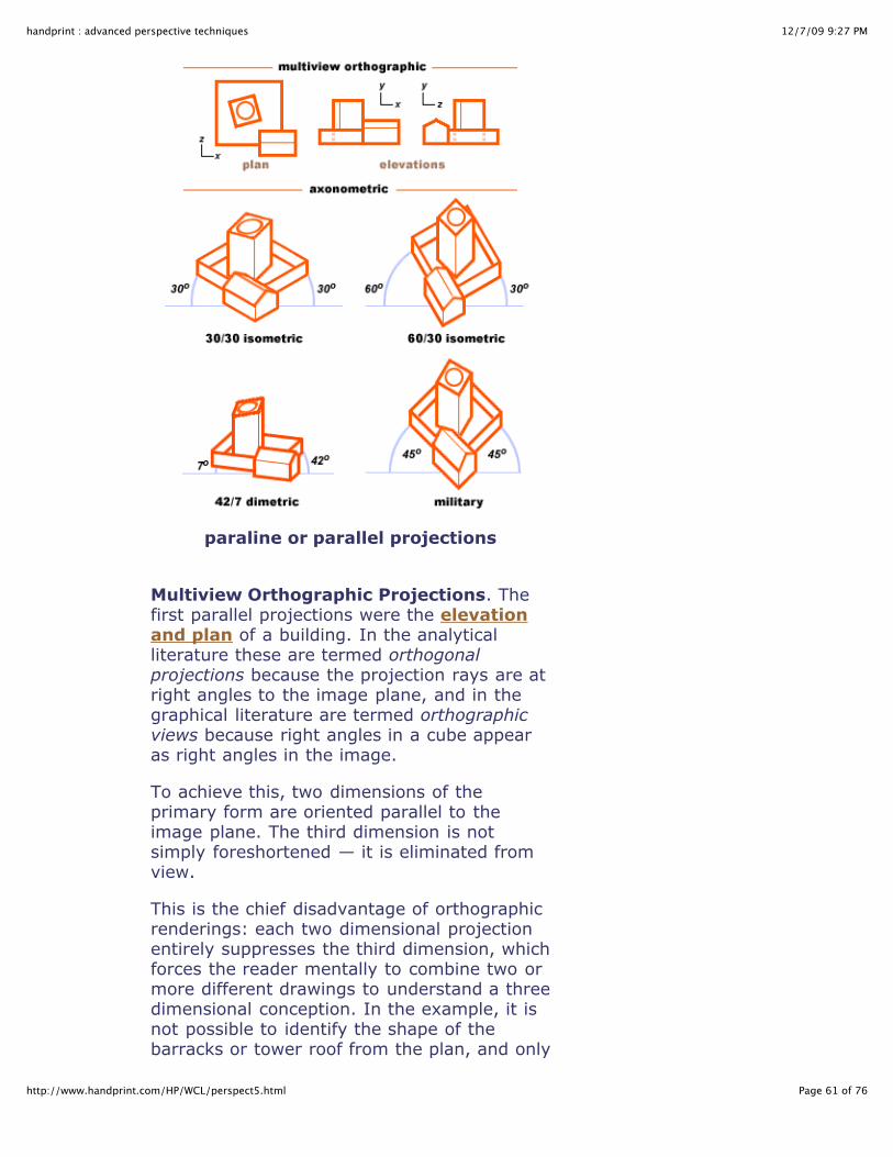
12/7/09 9:27 PMhandprint : advanced perspective techniques
Page 61 of 76http://www.handprint.com/HP/WCL/perspect5.html
paraline or parallel projections
Multiview Orthographic Projections. Thefirst parallel projections were the elevationand plan of a building. In the analyticalliterature these are termed orthogonalprojections because the projection rays are atright angles to the image plane, and in thegraphical literature are termed orthographicviews because right angles in a cube appearas right angles in the image.
To achieve this, two dimensions of theprimary form are oriented parallel to theimage plane. The third dimension is notsimply foreshortened — it is eliminated fromview.
This is the chief disadvantage of orthographicrenderings: each two dimensional projectionentirely suppresses the third dimension, whichforces the reader mentally to combine two ormore different drawings to understand a threedimensional conception. In the example, it isnot possible to identify the shape of thebarracks or tower roof from the plan, and only

12/7/09 9:27 PMhandprint : advanced perspective techniques
Page 62 of 76http://www.handprint.com/HP/WCL/perspect5.html
the y/z elevation shows that the barracksroof has a gable. Hence, multiple orthographicviews are necessary to completely understandthe physical shape of the form.
Axonometric Projections. In axonometricprojections, all three dimensions arerepresented as a two dimensional image; thethird or depth dimension is brought into theimage by drawing all three dimensions at anexplicit relative scale and interior angle.
The generic method for developing anaxonometric drawing is as follows: (1) startwith the plan drawn to scale, oriented toproduce the optimal paraline image; thehorizontal dimension is denoted x and thevertical dimension z; then select thecorresponding elevation at the same scaleand with the same horizontal dimension x andthe vertical dimension y; (2) construct allverticals y as parallel vertical lines in thedrawing, at either 1:1 scale or a reducedscale to the scale of the elevation; (3) drawall x dimensions at a constant angle tohorizontal, either to the left or right of theend points of verticals, at either 1:1 scale ora reduced scale to the scale of the elevation;and (4) draw all z dimensions at a constantangle and scale to horizontal, on the oppositeside of verticals from the x dimensions.
Within this generic mapping recipe, the onlygraphical variations in paraline projections arethe relative scale of the three dimensions andthe angles of the two other dimensions to thehorizontal.
30°/30° Isometric Projection. This isamong the most common paraline projectionsused today, so much so that "isometric" hasbecome synonymous with a paralineprojection. Analytically, this projection isproduced when all three front edges of a cubeare at an equal (~35.3°) angle to the imageplane. Graphically all three corner angles arerepresented by equal (120°) interior angles(e.g., the two nonvertical dimensions are at30° to a horizontal line), and all threedimensions are drawn in equal scale (1:1:1).

12/7/09 9:27 PMhandprint : advanced perspective techniques
Page 63 of 76http://www.handprint.com/HP/WCL/perspect5.html
Graphically, a 30°/30° isometric drawing isdefined as follows: (1) vertical (y) dimensionsare drawn vertical; (2) the x and zdimensions are drawn at a 30° angle to thehorizontal, and (3) all dimensions are drawnto the same scale. As a result, bothhorizontal and vertical circles are shown asellipses.
Standard isometric paraline drawings arefacilitated by the use of a preprinted isometricgrid (which consists of parallel vertical linescut by parallel lines at 60° and 30° angles tovertical) laid under the working surface, orsimilarly preruled sheets of architect's vellum,or the standard 30°/60°/90° draftingtriangles. In computational graphics (forexample, in Sim City), because of thelimitations of pixel representation, thegraphical angles are actually 26.6°, so thatoblique lines can be represented in ascendingor descending two pixel segments.
60°/30° Isometric Projection. Although itis visually pleasing and approximates verywell a similarly oriented 2PP perspectivedrawing, there are two problems with thestandard isometric format: (1) the plan is notreproduced, but appears compressed in alozenge form, and (2) this compressionaffects the appearance of many irregularforms (such as circles and spheres, orrectangular forms at odd angles to the threeprimary dimensions; cf. the "tower" in theexample drawing).
Both these problems are remedied by raisingone of the oblique dimensions to a 60° angleto the horizontal; now the drawing isplanometric (the plan is reproduced exactly inthe image), and as a result irregular formsare easier to interpret.
However, this introduces a new problem: thevertical dimension now appears exaggeratedor elongated. This can be partly remedied bydrawing the vertical dimension at 3/4 or 2/3scale.
45°/45° (Military) Isometric Projection.

12/7/09 9:27 PMhandprint : advanced perspective techniques
Page 64 of 76http://www.handprint.com/HP/WCL/perspect5.html
This is also an isometric projection becauseall three sides are in the same scale. This issometimes called a plan oblique projection orplanometric projection in the graphicalliterature because the plan angles anddimensions are reproduced exactly. (Note thatthe military "projection" is not orthogonal butis not oblique either: analytically, it is notpossible to produce the same image throughparallel lines at an oblique angle to the imageplane.)
The primary objection to military projection,as with the 60°/30° isometric, is that itappears to exaggerate the "depth" of thedrawing. As a result the z axis (for sidewaysviews) or the y axis (for downward views, asin the example) is sometimes shortened by1/2, creating a true dimetric drawing: this iscalled a cabinet projection.
42°/7° Dimetric Projection. Severalproposals have been made for paralineprojections that more closely approximatecentral perspective; these appear on casualinspection to be perspective drawings (at"telephoto" or very large object distances)although each dimension is in an exact,constant scale to the corresponding elevationsor plan. One proposal orients the two obliquedimensions at 7° and 42° to the horizontal;the length of the dimension at 42° is alsoreduced to a 1/2 scale.
Although these formats perform very well forcubic or rectangular forms, they are lesssuccessful for irregular forms, as appears inthe "tower" of the 42°/7° dimetric drawing.
Artistic Importance of ParalineProjections. Why should artists bother withthe rigid methods of technical drafting?Because perspective in all its aspects is aremarkably clear "laboratory" in which we canstudy many of the deep or complex problemsof artistic representation. In terms of art history, paraline projectionscharacterize classical Chinese and Japanesescroll paintings. In Europe, paraline

12/7/09 9:27 PMhandprint : advanced perspective techniques
Page 65 of 76http://www.handprint.com/HP/WCL/perspect5.html
representations became an important stylefeature of early 20th century painting; Cubistpaintings abound with examples of essentiallyplanometric or isometric designs, and CharlesSheeler produced a delightful painting (image,right) that combines planometric, isometricand dimetric images of rectagular or squareforms to suggest spatial volume whilecontradicting spatial recession; note theprecise way that the table legs intersect thesquare rug pattern behind. Sheeler wasobviously familiar with the conventions oftechnical drawing, and could deploy them togood artistic effect.
At a deeper level, both the orthographic andparaline projections represent differentsolutions to two fundamental and relatedartistic problems: simplification andschematization. All artists, whatever theirstyle or artistic goals, grapple continually withthese two problems.
Simplification is the decision to throw awayinformation — details, complexities,dimensions or features — in a way thatmakes other information clearer. Inorthographic projection the third dimension iseliminated. In both the orthographic andisometric projections, the object appears as ifviewed from infinitely far away, whichdiscards information about the physicallocation of the viewpoint in relation to theobjects in the image; the viewpoint isgenuinely imaginary.
Yet all projection drawings, paraline andperspective alike, retain the direction of viewas the average or parallel direction of theprojection lines. The back side of the object isnot represented and all angles are shown in aspecific and consistent relationship, either toeach other or to a vanishing point. This leadsus to the insight that simplification canquite often be paradoxical — how canthere be a direction of view if there is noviewpoint?! — and that by throwing awayinformation we actually create contradictionsor puzzles, in that sense making the image orvisual idea more complex conceptually if less
Charles Sheeler's Interior(1926)

12/7/09 9:27 PMhandprint : advanced perspective techniques
Page 66 of 76http://www.handprint.com/HP/WCL/perspect5.html
complex perceptually. Try looking for similarparadoxes in other kinds of artisticsimplification (cubism, fauvism,expressionism, abstract expressionism).
Schematization involves smoothing out theseconceptual paradoxes by making themconsistent or equivalent wherever theyappear, or by creating a hierarchy or systemof dominance among them. Althoughschematic choices are often arbitrary, andmay depend on subjective esthetic criteriasuch as clarity, harmony, emphasis, orcontrast, the schematic criteria can be chosenbecause there is a primary external audienceor purpose for the drawing which theschematic is adapted to serve. Thus, theobjection to some paraline drawings is thatthey appear to exaggerate one dimensionover another; the paraline schematizationmust be made more complex (for example,by using a dimetric or trimetric format insteadof a "simple" isometric format) in order forthe resulting image to be easier (simpler) tointerpret.
In general, "artistic style" refers to thestrategies used to simplify and complicate animage in ways that produce a visually oresthetically more desirable artifact. Thebeauty of paraline projections, and finepaintings, lies in the way they usesimplification and schematization to create amore legible and impactful image of theworld.
curvilinear perspectives
One of the most elusive but
apparently inspiring goals of perspectivestudies since the 19th century has beencurvilinear perspective, which involves therepresentation of space using vanishingcurves rather than vanishing lines. As thesecurves seem to converge at both ends, thehorizontal and vertical transversals create twovanishing points each with a fifth created bythe orthogonals parallel to the direction ofview. Hence the name five point perspective

12/7/09 9:27 PMhandprint : advanced perspective techniques
Page 67 of 76http://www.handprint.com/HP/WCL/perspect5.html
or spherical perspective for some of theseprojection systems. The appearance differences between linearand curvilinear perspective are shown in theexaggerated example at right. The linearprojection seems to push distant objectsfarther away, and to make nearby objectsloom too close, appear out of scale andexhibit gross distortions at the extreme ends.Curvilinear perspective crowds the side viewstoward the center of the image yet implicitlystrengthens the sense of personal presencethrough the rapidly increasing divergence inthe approaching orthogonals (lines in thefloor).
Curvilinear perspective has often beenjustified as part of a critique of linearperspective. Many objections arise from thewell known perspective "distortions". Thestandard (and completely effective) remedyfor these representational conflicts was totake a view of the subject from a largedistance, so that it fits within a reducedcircle of view, or to take an oblique viewso that the tapering of the horizontal orvertical elements was consistent with theeffect of one of the vanishing points. Howeverthese evasions are impractical in particular forthe representation of architectural interiors,such as the nave of a cathedral, where arestricted circle of view excludes an adequateview of the architecture.
I present here a similified method for makingyour own curvilinear drawings, and a longerreview of the historical justification forcurvilinear methods, with citations to bookswhere you can find more information.Unfortunately, the best of these are either outof print or untranslated, but a good universitylibrary may help you find them.
Constructing Curvilinear Drawings. Theperspective framework for making curvilinearprojections is tedious to set up but notdifficult to work out. Your goal is to make atemplate that represents a rectilinear (rightangled) grid of infinite height and width,
square columns and tilefloor
drawn in linear perspective
same setting as drawn incurvilinear perspective
(from Ulrich Graf, 1940)

12/7/09 9:27 PMhandprint : advanced perspective techniques
Page 68 of 76http://www.handprint.com/HP/WCL/perspect5.html
parallel to the picture plane, as imaged in thecurvilinear perspective system of your choice.You then draw this curvilinear grid within acircle of view, as shown for the sphericaltemplate below.
template for curvilinear transversals incentral (1PP) perspective
shown with 5° transversals and the normal 60° circle ofview, which equals a 70° circle of view in the spherical
projection
To use the grid to map a normal (linear)perspective drawing or photographic imageinto the new perspective space, you must firstsquare the drawing in the normal way.However, you must be careful to make theangular size of the squaring in the linearimage equal to the angular interval of thetransversals in the curvilinear grid, or theimage will appear in exaggerated distortion.(The template above uses a 5° interval, whichaccording to the distance/size table isroughly the same as a 1 foot width seen from11 feet away.) The final step is to copy theimage into the curvilinear grid, square bysquare, then clean up any inaccuracies as youprogress to the final state of the drawing orpainting.

12/7/09 9:27 PMhandprint : advanced perspective techniques
Page 69 of 76http://www.handprint.com/HP/WCL/perspect5.html
painting.
Constructing a similar grid in two pointperspective is much more complex, as thevanishing lines are foreshortened front toback. But good results are possible byconstructing the 2PP drawing in the normalway, squaring the drawing, and thenprojecting the drawing onto the curvilinearsurface using the grid above. (If you know ofa more explicit method for constructing a 2PPtemplate to any random rotation of the 2PPvanishing points, please email me.)
Historical Uses of Curvilinear Perspective.From the 16th to the 20th centuries,perspective theorists explored the problem ofanamorphic or geometrically distortedimages, which can be rectified back to anormal perspective image when viewed usingan appropriately curved mirror. These studiesoften overlapped with the problems ofprojective distortions in two dimensionalimages, specifically the difference inperspective view straight ahead and the viewobliquely to either side.
Curvilinear perspective was proposed at leastas early as 1624, in a pamphlet on meteorsby the Tübigen mathematician WilhelmSchickhardt (as quoted in Erwin Panofsky'sPerspective as Symbolic Form, 1924):
Schickhardt's "proof" of optical curves(1624)
"I say that all lines, even the straightest,which do not stand directly in front of theeye, or go through its axis, necessarily

12/7/09 9:27 PMhandprint : advanced perspective techniques
Page 70 of 76http://www.handprint.com/HP/WCL/perspect5.html
appear somewhat bent." Schickhardt'sargument is that the lines ab or cd appearlarge when close to the viewer (at V) butnecessarily and visibly grow smaller as theyrecede toward x or y; therefore "the sidesbecome narrower and necessarily curved; notlike a roof, to be sure, so as to produce asharp angle at points o and p, but rathergently and gradually, indeed unnoticeably,something like a belly, as is appropriate forsuch an arc."
Thus, if we stand at the base of a largetower, the masonry at eye level appears incentral perspective; if we look up, we see thesides near the top in converging three pointperspective. The same occurs in horizontallines when we stand facing a long wall, thenlook toward its end on either side.
However, the argument here is flawed, aswas pointed out by Schickhardt'scontemporary, the Danish astronomerJohannes Kepler. This becomes obvious if weexpress the "proof" as it appears in linearperspective:
the logical fallacy in optical curves
In this diagram, the break in the vanishinglines indicates that we are physically unableto see the image of the vanishing points xand y while directing our vision straightahead; to see them we must alter thedirection of view, and thereby completelychange the perspective geometry. If weturn our heads to one side while looking at aninfinitely long wall, then the convergence to xor y is produced by foreshortening of the

12/7/09 9:27 PMhandprint : advanced perspective techniques
Page 71 of 76http://www.handprint.com/HP/WCL/perspect5.html
image surface, now viewed at an angle, andthis convergence steadily increases as thedirection of view becomes parallel to thesurface of the wall.
These changes in our perspective view mustbe accounted for in the diagram by "broken"vanishing lines, to indicate that differentdirections of view apply between x and y.Schickhardt's curves are the average of anunaccounted number of different perspectiveprojections produced as the head and/or theimage plane is slowly turned from onedirection of view to another. In fact, hisargument originated in the observation of abolide, which traversed a large part of thenight sky and carried observers' rapt eyesalong with it.
But why stop there? One can also create apanoramaic photograph with a 360° view,which is optically impossible because the eyewould then have to be lens in all directions atthe same time that it would be retina on allsides. At some point, we accept thatcomposite images do not make validperceptual or perspective arguments and wepart company with Schickhardt.
Another 17th century argument was that theeye is an internally convex surface, and thismust cause the curvature in lines projectedonto it, an argument refuted empirically byM.H. Pirenne in his Optics, Painting andPhotography (1970). A more contemporaryargument is based on the appearance of wideangle or fisheye photographs, which showcurved lines projected into a flat photographand therefore seem to validate the curvinessof visual space. But in these photographs thedistance points in the image are compressedin the field of view, which shifts the virtualcenter of projection in front of theviewpoint.
In any case, it wasn't until the 19th centurythat curved vanishing lines were offered asbetter representations of extended horizontalor vertical recessions. The eccentric painterArthur Parsey (in 1836) and the amateur

12/7/09 9:27 PMhandprint : advanced perspective techniques
Page 72 of 76http://www.handprint.com/HP/WCL/perspect5.html
artist and astronomer William Herdman (in1853) published systems of perspective thatreplaced parallel transversals in central or twopoint perspective with slanting or curvedlines. These systems culminated in thesubjective perspective developed by theGerman mathematician Guido Hauck in1879. Long, lofty church interiors wereespecially popular set pieces for earlycurvilinear perspective representations, as inthis drawing by Herdman, which is surelyintended as a contrast to the many 18thcentury Dutch paintings of church interiors inperfect linear perspective.
architectural drawing in curvilinearperspective
Interior of Rosslyn Chapel by William Herdman (c.1850)
Curvilinear perspectives had a fitful historyafter the late 19th century, then saw aresurgence late in the 20th century. Seminalin this context were Erwin Panofsky'sPerspective as Symbolic Form (1924), basedon Hauck's mathematics; La perspectivecurviligne (1967, published in English asCurvilinear Perspective in 1987) by the Frenchtheorists Albert Flocon and André Barre, the"hyperbolic" system proposed by the artistRobert Hansen in 1973, and the "fisheye" orwide angle perspective developed by artistMichael Moose in 1986.
Several cultural or technological factors havebeen used to explain the development ofthese new systems, including 19th century

12/7/09 9:27 PMhandprint : advanced perspective techniques
Page 73 of 76http://www.handprint.com/HP/WCL/perspect5.html
advances in nonlinear geometries andcompound (wide angle) optics, perceptualexperiments in subjective curvature byHermann Helmholtz (in particular, thedemonstration that a row of widely spacedpoint lights, moved perpendicularly away froma viewer in complete darkness, appear tofollow a curved rather than straight lineconvergence), the discovery of subtlecurvatures in ancient Greek architecture,renewed interest in linear perspectivedistortions, the study of new types ofmapmaking projections, the unparalleled"wide angle" vistas made possible by moderniron towers, skyscrapers and air travel ... thelist is a long one.
I think the primary issue is much simpler.One of the founding ideas of the Renaissance,advocated by artists and scientists alike, wasthe fundamental unity between seeing andknowing. In this tradition, linear perspectivewas not so much a representation of seeingas an area where seeing and knowingoverlapped. Throughout the 16th century,mathematics and projective geometry, theprocedures of perspective drawing, and thetools and methods of surveying, navigationand astronomy were treated as differentaspects of the same fundamental discipline,and several of these topics were oftendiscussed together in a single book.
At the same time, artists from Leonardo toTurner were well aware of, and troubled by,the many ways linear perspective did notseem to accurately record all of visualexperience. By the 18th century, Europeanculture began to grapple seriously withproblems of color perception and visualillusion that demonstrated seeing was apsychological and subjective process, verydifferent from knowing and with its ownquirks and powers. This realization created afundamental divide that has expanded andramified in artistic practice ever since the late19th century.
Some artists pursued the representation ofvisual experience or "visual facts" separate

12/7/09 9:27 PMhandprint : advanced perspective techniques
Page 74 of 76http://www.handprint.com/HP/WCL/perspect5.html
from the "knowing" that comes fromperception. This was the point of departurefor many 19th century "seeing" artists (fromConstable to Monet to Bonnard), whodescribed their work as copying whatever wasavailable on their retinas; and for artists suchas Manet, Seurat or J.S. Sargent, whoanalyzed the process of vision by creatingimages from painterly visual deceptions,showing that what we see (or how we see)does not represent what is "actually there" onclose inspection.
In reaction, other artists rejected the visualfacts in favor of the insight or "knowing" thatseems to be the experiential fruit ofperception. That is, they found ways torepresent "higher realities" as a kind of visualexperience that has no explicit referent inoptical or static images — in particular,representations of spirituality and emotion.This highly diverse tradition emerges in"spiritual," "constructivist", "cubist","antiretinal," "conceptual","nonrepresentational" or "expressionist"artists as diverse as Matisse, Kandinsky,Duchamp, Picasso, Pollock, Riley, Rosenquistand Martin.
Against that background, curvilinearperspective seems to be a conservativereaction, an attempt to recreate the unionbetween seeing and knowing by altering rulesof seeing to correspond to the intuitions ofthree dimensional knowing. Certainly, alteringthe rules is explicit in the "argument foroptical curves" advanced centuries ago.
The consensus after more than a century ofdebate is that Panofsky and other critics oflinear perspective are factually wrong: noother two dimensional projection issuperior to standard methods of linearperspective when the perspective drawing isviewed with a single eye from the perspectiveviewpoint (center of projection). Under thoseconditions, a perspective drawing really doescapture exactly the visual angles of theoriginal scene — as demonstrated by M.H.Pirenne. Apparent perspective distortions

12/7/09 9:27 PMhandprint : advanced perspective techniques
Page 75 of 76http://www.handprint.com/HP/WCL/perspect5.html
arise because the image is not viewed fromthe correct center of projection and directionof view, or the perspective geometry ischanged, or different geometries are fusedinto a single image.
For me, that's the point: curvilinearperspective represents the state of lookingat the same time in many directions. Incontrast, I have repeatedly stressed thatlinear perspective is the image of a specificviewpoint and direction of view, and once thatrestriction is relaxed or abandoned, imagescan easily bend, flow or warp intounpredictable and highly expressive newgeometries.
place furstenberg, Paris, August 7,8,9by david hockney
Curvilinear perspective in effect averages orsummarizes the many possible views from asingle viewpoint, much as David Hockneyassembles an image from dozens or hundredsof localized, narrowly cropped photographs.In that context, curvilinear methods can bejustified as visually syncretic andphilosophically "postmodern".
Leonardo and many others after himidentified "flaws" in linear perspective onlybecause they considered the sameperspective situation from two or moredirections of view. Culturally we are nolonger predisposed to see multiple

12/7/09 9:27 PMhandprint : advanced perspective techniques
Page 76 of 76http://www.handprint.com/HP/WCL/perspect5.html
perspectives or multiple points of view asdisruptive affronts to orthodoxy.
Continue to Shadows, Reflections &Atmosphere
Last revised 03.31.2007 • © 2007 Bruce MacEvoy