

Advanced Networking - DISI, University of...
91
Advanced Networking Renato Lo Cigno [email protected] - Tel: 2026 Csaba Kiraly (helps with projects & Seminars) Dipartimento di Ingegneria e Scienza dell’Informazione Homepage: disi.unitn.it/locigno/ -> teching duties
-
Upload
hoangkhuong -
Category
Documents
-
view
225 -
download
1
Transcript of Advanced Networking - DISI, University of...
Advanced Networking
Renato Lo Cigno
[email protected] - Tel: 2026
Csaba Kiraly (helps with projects & Seminars)
Dipartimento di Ingegneria e Scienza dell’Informazione
Homepage:
disi.unitn.it/locigno/ -> teching duties

[email protected] Advanced Networking – Introduction 2
What do you find on the web site
• Exam Rules
• Exam Details ... should be on ESSE3, but ...
• Generic (useful) information
• Teaching Material: normally posted at least the day before the lesson
• Additional Material and links
• News, Bulletin, How to find and meet me, etc.
• ...
The web site is work in progress and updated frequently, so please drop by frequently and don’t blame ME if you did’t
read the last news ☺

[email protected] Advanced Networking – Introduction 3
Program
• Course Perspective– what do we learn and what we do not
– are there other “networks”
• Reharsal of basics– Internet and TCP/IP
– THE network? or YetAnother network
– IP
– UDP/TCP

[email protected] Advanced Networking – Introduction 4
Program
• IP and routing– OSPF and link-state protocols
• Intra AS routing
• performance driven routing
– BGP and policy-based protocols• External routing
• Cost (economical!) based routing
– Global routing and Internet topology• How things look and works end-to-end

[email protected] Advanced Networking – Introduction 5
Program
• Network congestion– Network load and stability
– Call Admission Control
– Reactive congestion control• Closed-loop systems
• Implicit/Explicit
• Forward
• Backward
– TCP• How it really works
– TCP stabilization methods: mith and reality• RED, RIO, ...
[email protected] Advanced Networking – Introduction 6
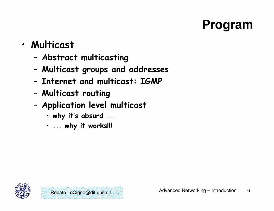
Program
• Multicast– Abstract multicasting
– Multicast groups and addresses
– Internet and multicast: IGMP
– Multicast routing
– Application level multicast• why it’s absurd ...
• ... why it works!!!

[email protected] Advanced Networking – Introduction 7
Program
• Internet multimedia communications– Voice and Video services on packet-based networks
– Transport: RTP/RTCP
– SIP standard
– H.323 standard
– Skype and P2P approaches
– IP TV• VoD/Broadcast/Live
• Traditional approach
• P2P systems

• Recalling known topics:
- Internet
- IP- UDP/TCP
Acknowledment:
The following slides are based on the slides developed by
J.Kurose and K.Ross to accompany their book “Computer Networks:
A Top Down Approach Featuring the Internet” by Wiley edts.

[email protected] Advanced Networking – Introduction 9
Internet
What we see:• Services
• Applications we use
• Some “application level” protocols
• Throughput
• Losses
• Delay (sometimes)
• Delay Jitter (if we’re really skilled!)
What is it:• A collection of protocols
• Mainly centered around two centerpieces:
– IP (network layer)
– UDP/TCP (transport layer)
• Does not mandate a physical medium or format
• Does not mandate or limit the services/applications above (integrates services)

[email protected] Advanced Networking – Introduction 10
IP: The Network Layer
Goals:• recall principles
behind network layer services:– routing (path
selection)
– dealing with scale
– how a router works
• instantiation and implementation in the Internet
Overview:• network layer services
• routing principle: path selection
• IP
• Internet routing protocols reliable transfer– intra-domain
– inter-domain
• what’s inside a router?

[email protected] Advanced Networking – Introduction 11
Network layer functions• transport packet from
sending to receiving hosts
• network layer protocols in every host, router
three important functions:
• path determination: route taken by packets from source to dest. Routing algorithms
• switching: move packets from router’s input to appropriate router output
• call setup: some network architectures require router call setup along path before data flows
networkdata linkphysical
networkdata linkphysical
networkdata linkphysical
networkdata linkphysical
networkdata linkphysical
networkdata linkphysical
networkdata linkphysical
networkdata linkphysical
applicationtransportnetworkdata linkphysical
applicationtransportnetworkdata linkphysical

[email protected] Advanced Networking – Introduction 12
Network service model
Q: What service modelfor “channel” transporting packets from sender to receiver?
• guaranteed bandwidth?
• preservation of inter-packet timing (no jitter)?
• loss-free delivery?
• in-order delivery?
• congestion feedback to sender?
? ??virtual circuit
or datagram?
The most importantabstraction provided by network layer:
serv
ice
abst
ract
ion

[email protected] Advanced Networking – Introduction 13
Virtual circuits
• call setup, teardown for each call before data can flow
• each packet carries VC identifier (not destination host OD)
• every router on source-dest path s maintain “state” for each passing connection– transport-layer connection only involved two end systems
• link, router resources (bandwidth, buffers) may be allocated to VC– to get circuit-like perf.
“source-to-dest path behaves much like telephone circuit”– performance-wise
– network actions along source-to-dest path

[email protected] Advanced Networking – Introduction 14
Virtual circuits: signaling protocols
• used to setup, maintain teardown VC
• used in ATM, frame-relay, X.25
• not used in today’s Internet
applicationtransportnetworkdata linkphysical
applicationtransportnetworkdata linkphysical
1. Initiate call 2. incoming call
3. Accept call4. Call connected5. Data flow begins 6. Receive data

[email protected] Advanced Networking – Introduction 15
Datagram networks: the Internet model
• no call setup at network layer
• routers: no state about end-to-end connections– no network-level concept of “connection”
• packets typically routed using destination host ID– packets between same source-dest pair may take
different paths
applicationtransportnetworkdata linkphysical
applicationtransportnetworkdata linkphysical
1. Send data 2. Receive data
[email protected] Advanced Networking – Introduction 16
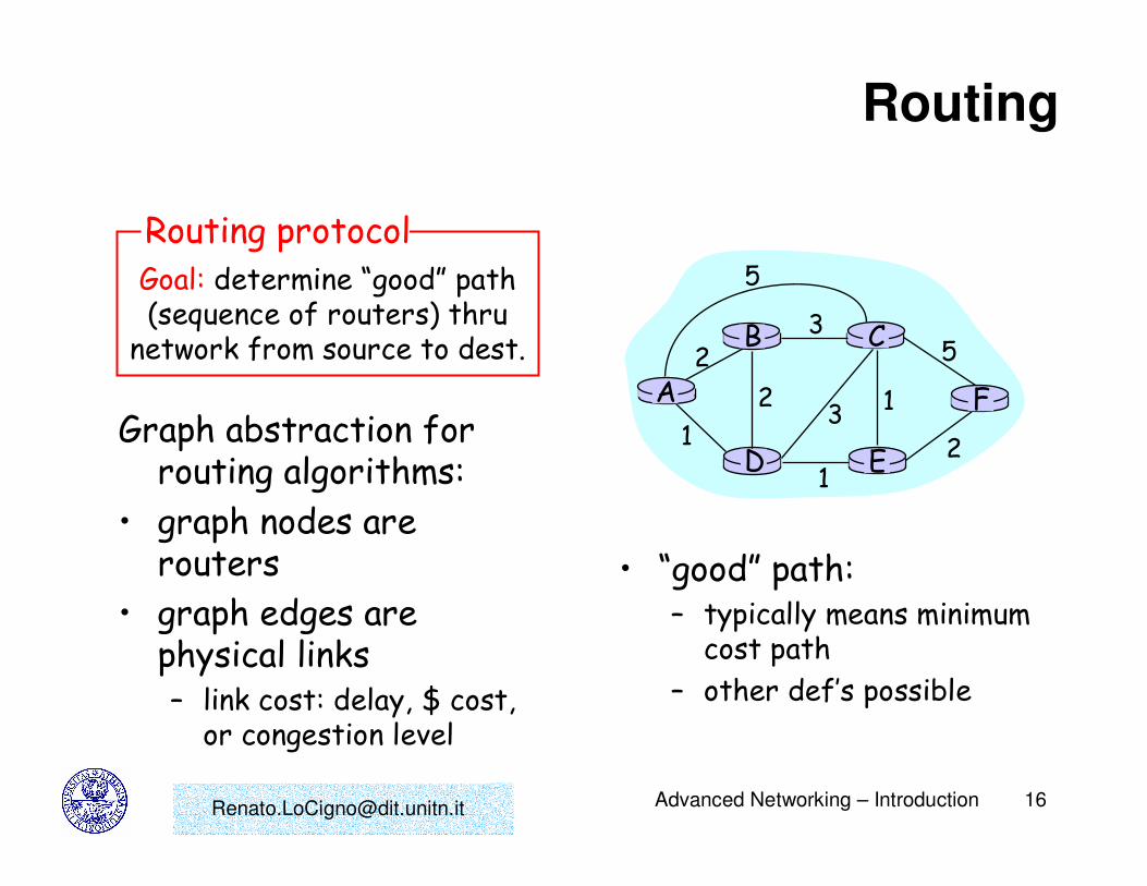
Routing
Graph abstraction for routing algorithms:
• graph nodes are routers
• graph edges are physical links– link cost: delay, $ cost,
or congestion level
Goal: determine “good” path(sequence of routers) thru
network from source to dest.
Routing protocol
A
ED
CB
F
2
2
13
1
1
2
53
5
• “good” path:– typically means minimum
cost path
– other def’s possible

[email protected] Advanced Networking – Introduction 17
Routing Algorithm classification
Global or decentralized information?
Global:
• all routers have complete topology, link cost info
• “link state” algorithms
Decentralized:
• router knows physically-connected neighbors, link costs to neighbors
• iterative process of computation, exchange of info with neighbors
• “distance vector” algorithms
Static or dynamic?Static:
• routes change slowly over time
Dynamic:
• routes change more quickly
– periodic update
– in response to link cost changes
[email protected] Advanced Networking – Introduction 18
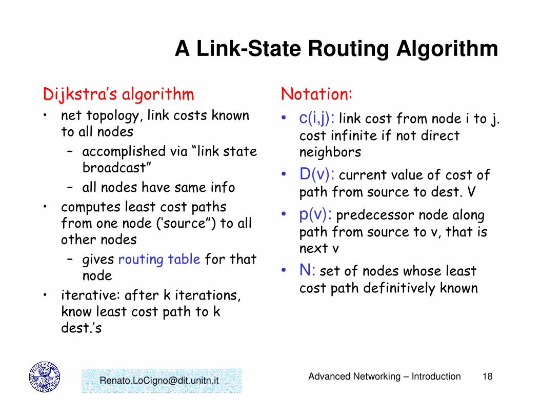
A Link-State Routing Algorithm
Dijkstra’s algorithm• net topology, link costs known
to all nodes
– accomplished via “link state broadcast”
– all nodes have same info
• computes least cost paths from one node (‘source”) to all other nodes
– gives routing table for that node
• iterative: after k iterations, know least cost path to k dest.’s
Notation:
• c(i,j): link cost from node i to j. cost infinite if not direct neighbors
• D(v): current value of cost of path from source to dest. V
• p(v): predecessor node along path from source to v, that is next v
• N: set of nodes whose least cost path definitively known

[email protected] Advanced Networking – Introduction 19
Dijsktra’s Algorithm
1 Initialization:
2 N = {A}
3 for all nodes v
4 if v adjacent to A
5 then D(v) = c(A,v)
6 else D(v) = infty
7
8 Loop
9 find w not in N such that D(w) is a minimum
10 add w to N
11 update D(v) for all v adjacent to w and not in N:
12 D(v) = min( D(v), D(w) + c(w,v) )
13 /* new cost to v is either old cost to v or known
14 shortest path cost to w plus cost from w to v */
15 until all nodes in N

[email protected] Advanced Networking – Introduction 20
Dijkstra’s algorithm: example
Step
0
1
2
3
4
5
start N
A
AD
ADE
ADEB
ADEBC
ADEBCF
D(B),p(B)
2,A
2,A
2,A
D(C),p(C)
5,A
4,D
3,E
3,E
D(D),p(D)
1,AD(E),p(E)
infinity
2,D
D(F),p(F)
infinity
infinity
4,E
4,E
4,E
A
ED
CB
F
2
2
13
1
1
2
53
5

[email protected] Advanced Networking – Introduction 21
Dijkstra’s algorithm, discussion
Algorithm complexity: n nodes
• each iteration: need to check all nodes, w, not in N
• n*(n+1)/2 comparisons: O(n**2)
• more efficient implementations possible: O(nlogn)
Oscillations possible:
• e.g., link cost = amount of carried traffic
A
D
C
B1 1+e
e0
e
1 1
0 0
A
D
C
B2+e 0
001+e 1
A
D
C
B0 2+e
1+e10 0
A
D
C
B2+e 0
e01+e 1
initially… recompute
routing… recompute … recompute

[email protected] Advanced Networking – Introduction 22
Distance Vector Routing Algorithm
iterative:• continues until no
nodes exchange info.
• self-terminating: no “signal” to stop
asynchronous:• nodes need not
exchange info/iterate in lock step!
distributed:
• each node communicates only with directly-attached neighbors
Distance Table data structure• each node has its own
• row for each possible destination
• column for each directly-attached neighbor to node
• example: in node X, for dest. Y via neighbor Z:
D (Y,Z)X
distance from X to
Y, via Z as next hop
c(X,Z) + min {D (Y,w)}Z
w
=
=

[email protected] Advanced Networking – Introduction 23
Distance Table: example
A
E D
CB7
8
1
2
1
2
D ()
A
B
C
D
A
1
7
6
4
B
14
8
9
11
D
5
5
4
2
Ecost to destination via
de
st in
atio
n
D (C,D)E
c(E,D) + min {D (C,w)}D
w=
= 2+2 = 4
D (A,D)E
c(E,D) + min {D (A,w)}D
w=
= 2+3 = 5
D (A,B)E
c(E,B) + min {D (A,w)}B
w=
= 8+6 = 14
loop!
loop!

[email protected] Advanced Networking – Introduction 24
Distance table gives routing table
D ()
A
B
C
D
A
1
7
6
4
B
14
8
9
11
D
5
5
4
2
Ecost to destination via
de
st in
atio
n
A
B
C
D
A,1
D,5
D,4
D,4
Outgoing link
to use, cost
de
st in
atio
n
Distance table Routing table

[email protected] Advanced Networking – Introduction 25
Distance Vector Routing: overview
Iterative, asynchronous: each local iteration caused by:
• local link cost change
• message from neighbor: its least cost path change from neighbor
Distributed:
• each node notifies neighbors only when its least cost path to any destination changes– neighbors then notify
their neighbors if necessary
wait for (change in local link
cost of msg from neighbor)
recompute distance table
if least cost path to any dest
has changed, notifyneighbors
Each node:
[email protected] Advanced Networking – Introduction 26
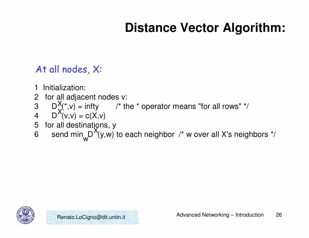
Distance Vector Algorithm:
1 Initialization:
2 for all adjacent nodes v:
3 D (*,v) = infty /* the * operator means "for all rows" */
4 D (v,v) = c(X,v)
5 for all destinations, y
6 send min D (y,w) to each neighbor /* w over all X's neighbors */
XX
Xw
At all nodes, X:

[email protected] Advanced Networking – Introduction 27
Distance Vector Algorithm (cont.):8 loop
9 wait (until I see a link cost change to neighbor V
10 or until I receive update from neighbor V)
11
12 if (c(X,V) changes by d)
13 /* change cost to all dest's via neighbor v by d */
14 /* note: d could be positive or negative */
15 for all destinations y: D (y,V) = D (y,V) + d
16
17 else if (update received from V wrt destination Y)
18 /* shortest path from V to some Y has changed */
19 /* V has sent a new value for its min DV(Y,w) */
20 /* call this received new value is "newval" */
21 for the single destination y: D (Y,V) = c(X,V) + newval
22
23 if we have a new min D (Y,w)for any destination Y
24 send new value of min D (Y,w) to all neighbors
25
26 forever
w
XX
X
X
X
w
w

[email protected] Advanced Networking – Introduction 28
Distance Vector Algorithm: example
X Z72
1
Y

[email protected] Advanced Networking – Introduction 29
Distance Vector Algorithm: example
X Z72
1
Y
D (Y,Z)X
c(X,Z) + min {D (Y,w)}w=
= 7+1 = 8
Z
D (Z,Y)X
c(X,Y) + min {D (Z,w)}w=
= 2+1 = 3
Y

[email protected] Advanced Networking – Introduction 30
Distance Vector: link cost changes
Link cost changes:• node detects local link cost change
• updates distance table (line 15)
• if cost change in least cost path, notify neighbors (lines 23,24)
X Z14
50
Y1
algorithmterminates“good
news travelsfast”
[email protected] Advanced Networking – Introduction 31
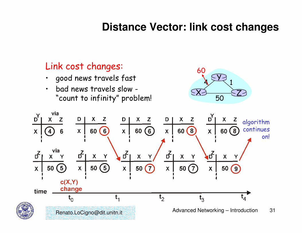
Distance Vector: link cost changes
Link cost changes:• good news travels fast
• bad news travels slow -“count to infinity” problem!
X Z14
50
Y60
algorithmcontinues
on!

[email protected] Advanced Networking – Introduction 32
Distance Vector: poisoned reverse
If Z routes through Y to get to X :• Z tells Y its (Z’s) distance to X is
infinite (so Y won’t route to X via Z)
• will this completely solve count to infinity problem?
X Z14
50
Y60
algorithmterminates

[email protected] Advanced Networking – Introduction 33
Comparison of LS and DV algorithms
Message complexity• LS: with n nodes, E links,
O(nE) msgs sent each
• DV: exchange between neighbors only
– convergence time varies
Speed of Convergence• LS: O(n**2) algorithm
requires O(nE) msgs
– may have oscillations
• DV: convergence time varies
– may be routing loops
– count-to-infinity problem
Robustness: what happens if router malfunctions?
LS:– node can advertise
incorrect link cost
– each node computes only its own table
DV:– DV node can advertise
incorrect path cost
– each node’s table used by others • error propagate thru
network

[email protected] Advanced Networking – Introduction 34
The Internet Network layer
routingtable
Host, router network layer functions:
Routing protocols•path selection•RIP, OSPF, BGP
IP protocol•addressing conventions•datagram format•packet handling conventions
ICMP protocol•error reporting•router “signaling”
Transport layer: TCP, UDP
Link layer
physical layer
Networklayer

[email protected] Advanced Networking – Introduction 35
Why different Intra- and Inter-AS routing ?
• Policy: Inter is concerned with policies (which provider we must select/avoid, etc). Intra is contained in a single organization, so, no policy decisions necessary
• Scale: Inter provides an extra level of routing table size and routing update traffic reduction above the Intra layer
• Performance: Intra is focused on performance metrics; needs to keep costs low. In Inter it is difficult to propagate performance metrics efficiently (latency, privacy etc). Besides, policy related information is more meaningful.
We need BOTH!

[email protected] Advanced Networking – Introduction 36
IP Addressing• IP address: 32-bit identifier for host, router interface
• interface: connection between host, router and physical link– router’s typically have
multiple interfaces
– host may have multiple interfaces
– IP addresses associated with interface, not host, router, …
• Address mng & resolution + DNS must be known well we do not repeat it
223.1.1.1
223.1.1.2
223.1.1.3
223.1.1.4 223.1.2.9
223.1.2.2
223.1.2.1
223.1.3.2223.1.3.1
223.1.3.27
223.1.1.1 = 11011111 00000001 00000001 00000001
223 1 11

[email protected] Advanced Networking – Introduction 37
Router Architecture Overview
• Router main functions: routing algorithms and protocols processing, switching datagrams from an incoming link to an outgoing link
Router Components

[email protected] Advanced Networking – Introduction 38
Input Ports
• Decentralized switching: perform routing table lookup using a copy of the node routing table stored in the port memory
• Goal is to complete input port processing at ‘line speed’, ie processing time =< frame reception time (eg, with 2.5 Gbps line, 256 bytes long frame, router must perform about 1 million routing table lookups in a second)
• Queuing occurs if datagrams arrive at rate higher than can be forwarded on switching fabric

[email protected] Advanced Networking – Introduction 39
Speeding Up Routing Table Lookup
• Table is stored in a tree structure to facilitate binary search
• Content Addressable Memory (associative memory), eg Cisco 8500 series routers
• Caching of recently looked-up addresses
• Compression of routing tables

[email protected] Advanced Networking – Introduction 41
Switching Via Memory
•First generation routers: packet is copied under system’s (single) CPU control; speed limited by Memory bandwidth. For Memory speed of B packet/sec or pps, throughput is B/2 pps
Input
Port
Output
Port
Memory
System Bus
• Modern routers: input ports with CPUs that implement output
port lookup, and store packets in appropriate locations (= switch)
in a shared Memory; eg Cisco Catalyst 8500 switches

[email protected] Advanced Networking – Introduction 42
Switching Via Bus
• Input port processors transfer a datagram from input port memory to output port memory via a shared bus
• Main resource contention is over the bus; switching is limited by bus speed
• Sufficient speed for access and enterprise routers (not regional or backbone routers) is provided by a Gbps bus; eg Cisco 1900 which has a 1 Gbps bus
[email protected] Advanced Networking – Introduction 43
Switching Via An Interconnection Network
• Used to overcome bus bandwidth limitations
• Banyan networks and other interconnection networks were initially developed to connect processors in a multiprocessor computer system; used in Cisco 12000 switches provide up to 60 Gbps through the interconnection network
• Advanced design incorporates fragmenting a datagram into fixed length cells and switch the cells through the fabric; + better sharing of the switching fabric resulting in higher switching speed

[email protected] Advanced Networking – Introduction 44
Output Ports
Buffering is required to hold datagrams whenever they arrive from the switching fabric at a rate faster than the transmission rate

[email protected] Advanced Networking – Introduction 45
Queuing At Input and Output Ports• Queues build up whenever there is a rate mismatch or blocking.
Consider the following scenarios:
– Fabric speed is faster than all input ports combined; more datagrams are destined to an output port than other output ports; queuing occurs at output port
– Fabric bandwidth is not as fast as all input ports combined; queuing may occur at input queues;
– HOL blocking: fabric can deliver datagrams from input ports in parallel, except if datagrams are destined to same output port; in this case datagrams are queued at input queues; there may be queued datagrams that are held behind HOL conflict, even when their output port is available

[email protected] Advanced Networking – Introduction 46
Transport Layer: UDP & TCP
Goals:• Recall principles behind
transport layer services:– multiplexing/demultiplex
ing
– reliable data transfer
– flow control
– congestion control
• instantiation and implementation in the Internet
Overview:• transport layer services
• multiplexing/demultiplexing
• connectionless transport: UDP
• principles of reliable data transfer
• connection-oriented transport: TCP– reliable transfer
– flow control
– connection management

[email protected] Advanced Networking – Introduction 47
Transport services and protocols
• provide logical communicationbetween app’ processes running on different hosts
• transport protocols run in end systems (primarily)
transport vs network layer services:
• network layer: data transfer between end systems
• transport layer: data transfer between processes – relies on, enhances, network
layer services
applicationtransportnetworkdata linkphysical
applicationtransportnetworkdata linkphysical
networkdata linkphysical
networkdata linkphysical
networkdata linkphysical
networkdata linkphysicalnetwork
data linkphysical
logical end-end transport

[email protected] Advanced Networking – Introduction 48
Transport-layer protocols
Internet transport services:
• reliable, in-order unicastdelivery (TCP)– congestion
– flow control
– connection setup
• unreliable (“best-effort”), unordered unicast or multicast delivery: UDP
• services not available: – real-time
– bandwidth guarantees
– reliable multicast
applicationtransportnetworkdata linkphysical
applicationtransportnetworkdata linkphysical
networkdata linkphysical
networkdata linkphysical
networkdata linkphysical
networkdata linkphysicalnetwork
data linkphysical
logical end-end transport

[email protected] Advanced Networking – Introduction 49
applicationtransportnetwork
MP2
applicationtransportnetwork
Multiplexing/demultiplexing
Recall: segment - unit of data exchanged between transport layer entities
– aka TPDU: transport protocol data unit
receiver
Ht
Hn
Demultiplexing: delivering received segments (TPDUs)tocorrect app layer processes
segment
segment M
applicationtransportnetwork
P1M
M M
P3 P4
segmentheader
application-layerdata

[email protected] Advanced Networking – Introduction 50
Multiplexing/demultiplexing
multiplexing/demultiplexing:
• based on sender, receiver port numbers, IP addresses
– source, dest port #s in each segment
– recall: well-known port numbers for specific applications
source port # dest port #
32 bits
applicationdata
(message)
other header fields
TCP/UDP segment format
gathering data from multipleapp processes, enveloping data with header (later used for demultiplexing)
Multiplexing:

[email protected] Advanced Networking – Introduction 51
Multiplexing/demultiplexing: examples
host A server Bsource port: xdest. port: 23
source port:23dest. port: x
port use: simple telnet app
WWW clienthost A
WWWserver B
WWW clienthost C
Source IP: CDest IP: B
source port: xdest. port: 80
Source IP: CDest IP: B
source port: ydest. port: 80
port use: WWW server
Source IP: ADest IP: B
source port: xdest. port: 80

[email protected] Advanced Networking – Introduction 52
UDP: User Datagram Protocol [RFC 768]
• “no frills,” “bare bones” Internet transport protocol
• “best effort” service, UDP segments may be:
– lost
– delivered out of order to app
• connectionless:– no handshaking between
UDP sender, receiver
– each UDP segment handled independently of others
Why is there a UDP?• no connection
establishment (which can add delay)
• simple: no connection state at sender, receiver
• small segment header
• no congestion control: UDP can blast away as fast as desired

[email protected] Advanced Networking – Introduction 53
UDP: more
• often used for streaming multimedia apps
– loss tolerant
– rate sensitive
• other UDP uses (why?):– DNS
– SNMP
• reliable transfer over UDP: add reliability at application layer
– application-specific error recover!
source port # dest port #
32 bits
Applicationdata
(message)
UDP segment format
length checksumLength, in
bytes of UDPsegment,includingheader

[email protected] Advanced Networking – Introduction 54
UDP checksum
Sender:• treat segment contents as
sequence of 16-bit integers
• checksum: addition (1’s complement sum) of segment contents
• sender puts checksum value into UDP checksum field
Receiver:• compute checksum of
received segment
• check if computed checksum equals checksum field value:
– NO - error detected
– YES - no error detected. But maybe errors nonethless?
Goal: detect “errors” (e.g., flipped bits) in transmitted segment

[email protected] Advanced Networking – Introduction 55
Principles of Reliable data transfer
• important in app., transport, link layers
• top-10 list of important networking topics!
• characteristics of unreliable channel will determine complexity of reliable data transfer protocol (rdt)

[email protected] Advanced Networking – Introduction 56
Reliable data transfer: getting started
sendside
receiveside
rdt_send(): called from above, (e.g., by app.). Passed data to deliver to receiver upper layer
udt_send(): called by rdt,to transfer packet over
unreliable channel to receiver
rdt_rcv(): called when packet arrives on rcv-side of channel
deliver_data(): called by rdt to deliver data to upper

[email protected] Advanced Networking – Introduction 57
Reliable data transfer: getting started
We’ll:
• incrementally develop sender, receiver sides of reliable data transfer protocol (rdt)
• consider only unidirectional data transfer– but control info will flow on both directions!
• use finite state machines (FSM) to specify sender, receiver
state1
state2
event causing state transitionactions taken on state transition
state: when in this “state” next state
uniquely determined by next event
eventactions
[email protected] Advanced Networking – Introduction 58
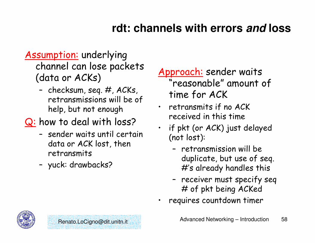
rdt: channels with errors and loss
Assumption: underlying channel can lose packets (data or ACKs)– checksum, seq. #, ACKs,
retransmissions will be of help, but not enough
Q: how to deal with loss?– sender waits until certain
data or ACK lost, then retransmits
– yuck: drawbacks?
Approach: sender waits “reasonable” amount of time for ACK
• retransmits if no ACK received in this time
• if pkt (or ACK) just delayed (not lost):
– retransmission will be duplicate, but use of seq. #’s already handles this
– receiver must specify seq# of pkt being ACKed
• requires countdown timer

[email protected] Advanced Networking – Introduction 62
Performance of rdt
• rdt works, but performance stinks
• example: 1 Gbps link, 15 ms e-e prop. delay, 1KB packet:
Ttransmit =8kb/pkt10**9 b/sec
= 8 microsec
Utilization = U = =8 microsec
30.016 msecfraction of time
sender busy sending= 0.00015
– 1KB pkt every 30 msec -> 33kB/sec thruput over 1 Gbps link
– network protocol limits use of physical resources!

[email protected] Advanced Networking – Introduction 63
Pipelined Protocols• Channel utilization under a Stop&Wait protocol is not
high when the propagation time is long relative to the transmission time
• Solution: pipelined protocols, where more than one packet can be sent without waiting for feedback, thus filling the ‘pipeline’
• Two major versions (and lots of variations on the theme):– Go-Back-N
– Selective Repeat
• New requirements: – Buffering more than one packet at sender, and possibly at
receiver too
– Larger sequence numbers for identifying packets in transit

[email protected] Advanced Networking – Introduction 65
Stop&Wait Efficiency
Sender Receiver
datatransT
propT
propT
procT
acktransT
product
"" thecalled
is which , case in this
1/C; data, ofbit oneFor
Speed.on Transmissi theis C andlength
Packet theis L where,
where,*21
1
or , *2
and small relativelyFor
*2
Delay-Bandwidth
prop
datatrans
datatrans
datatrans
prop
propdatatrans
datatrans
acktransproc
acktransprocpropdatatrans
datatrans
CTa
T
C
LT
T
Ta
aU
TT
TU
TT
TTTT
TU
=
=
=
=
+
≈
+
≈
+++
=

[email protected] Advanced Networking – Introduction 66
Go-Back-N
• Sender can go ahead and transmit packets without waiting for feedback up to some number of packets (for flow control reasons, details later)
• Definitions: N: maximum allowable number of transmission without
feedback
Base: lowest sequence number of unacked packets
Nextseqnum: lowest unused sequence number
Maxseqnum: largest sequence number

[email protected] Advanced Networking – Introduction 67
Go-Back-N Window
• From definitions and figure above:[0, base-1] transmitted and acked
[base, nextseqnum-1] transmitted and waiting for feedback, or ‘outstanding’
[nextseqnum, base+N-1] numbers that can be used when packets are provided by higher layer for transmission
[base+N, maxseqnum] numbers that cannot be used until more packets are acked

[email protected] Advanced Networking – Introduction 68
• Because of the window metaphor, these protocols are also referred to as sliding window protocols
• Stop&Wait can be viewed as a sliding window protocol, with window size N = 1, and sequence space = [0,1]
• Sequence number is carried in a fixed length field in the packet header; with k bits in the Sequence number field, the sequence space is
• Since sequence numbers must wrap around, all sequence number arithmetic is modulo
Go-Back-N Window (Cont.)

[email protected] Advanced Networking – Introduction 69
Go-Back-N Sender
Window NOT full
No other packets outstanding
Acks are cumulative
?No packets
outstanding

[email protected] Advanced Networking – Introduction 70
Go-Back-N Receiver
• Receiver accepts packets in order only! out-of-order packets are
simply dropped

[email protected] Advanced Networking – Introduction 72
Go-Back-N Performance
• Bandwidth-Delay Product (ie “pipeline size”) is defined as the product of the channel transmission speed and the propagation delay
• As transmission speed or propagation delay increases, more packets can be transmitted to “fill the pipeline”
• For channels with high Bandwidth-Delay product, Go-Back-N performance may deteriorate: the number of outstanding packets may be large and all these packets will be unnecessarily retransmitted when an error occurs
[email protected] Advanced Networking – Introduction 73
Selective Repeat
• Selective Repeat addresses the performance limitation of Go-back-N mentioned above
• Receiver indicates to sender which packet needs to be retransmitted; sender retransmits only that packet
• Receiver accepts and buffers packets received out of order within a limit imposed by a receiver window
• Groups of packets with consecutive sequence numbers (or completed sequences) are delivered to the higher layer at the sender
• A timer must be associated with each packet (but we can use one hardware timer to implement multiple logical timers)

[email protected] Advanced Networking – Introduction 75
Selective Repeat Sender Event-Driven Algorithms
• Higher layer calls to transmit data: if there are unused sequence numbers
then packetize and transmit;
else reject the data;
• Timeout occurs:transmit the (single) packet which timed out;
• Ack is received:mark packet acked;
if base can be moved then move it to the unacked packet with the lowest sequence
number;
[email protected] Advanced Networking – Introduction 76
Selective Repeat Receiver Event-Driven Algorithms
• Packet received, not corrupted, within current receive window:Ack the received packet;
if not previously receivedthen buffer the packet;
deliver consectively sequenced received packets to higher layer;
move window forward;
• Packet received, not corrupt, sequence number below window base:Ack the received packet; /* packet previously acked and already
delivered to higher layer*/
• Packet received, corrupt, or sequence number beyond window:Ignore the packet

[email protected] Advanced Networking – Introduction 78
Setting The Window Size
• The window size N is an important parameter
• N should be large enough to allow filling the pipeline, thus making better utilization of the channel
• On the other hand, N is limited by the protocols (ensure receiver correctly identifies packets)
• It was found that N cannot be larger than half the sequence space length

[email protected] Advanced Networking – Introduction 80
Reliable Transport Layer: TCP
• Full-duplex
• End-to-end protocol, transparent to network and lower layers in routers
• Connection-oriented, connection established through “three way handshake” protocol
• Byte Stream transfer, stream is divided into segments with a maximum segment size (MSS)
• Reliability through an ARQ type protocol
• Flow Control: receiver controls the amount of bytesa sender is allowed to send
• Point-to-point connection, no multicasting with TCP

[email protected] Advanced Networking – Introduction 82
Telnet: A TCP ACK example
• Telnet: appl. level protocol for remote login
• Interactive mode; typed characters are “echoed back” by remote Host (each character traverses the network twice)
• Full duplex stream of characters provides opportunity for ACK piggybacking
• In simplex (one way) data transfer, explicit ACKs are required

[email protected] Advanced Networking – Introduction 84
TCP Reliable Data Transfer
• IP layer is often unreliable: packet drop (due to buffer overflow); data corruption (eg, noise, collisions).
• TCP approach: data is retransmitted following error detection (bad checksum) or packet loss detection (timeout or out of sequence reception)
• TCP uses pipelining to improve efficiency over paths with many hops and large end to end delays
• TCP error recovery mechanism similar to Go-Back-N
• TCP RFCs do not require receivers to drop out-of-order packets; some implementation keep such packets to save channel bandwidth

[email protected] Advanced Networking – Introduction 85
Three Key Events In Reliable TCP
• Event 1: TCP releases data segment to IP layer; segment retx timer started
• Event 2: segment timeout expires: segment is retransmitted
• Event 3: sender receives an ACK: (a) First Time ACK, ie the ACK is for data not acked
before (nextseqnum > ACK # > sendbase); the sender updates TCP state variables (sendbase, timer etc)
(b) Duplicate ACK (ACK # < or = sendbase); it re-ACKs old segments.

[email protected] Advanced Networking – Introduction 86
Sender Reaction To Duplicate ACKs
• Duplicate ACK (last ACK #) returned by receiver if: (a) segment received out of order (seq num larger than
expected)
(b) old segment received
• Sender ignores first two duplicate ACKs (timers still in force)
• Upon receiving THIRD duplicate ACK, the sender infers that the segment was indeed lost (as opposed to delayed); sender retransmits segment without waiting for timeout.

[email protected] Advanced Networking – Introduction 87
Flow/Congestion Control
• Flow Control (strict definition): regulate TCP flow so as to prevent receive buffer overflow at destination
• Flow Control (more general definition): regulate TCP flow so as to prevent buffer overflow anywhere along the path
• Congestion Control: regulate TCP flow(s) so as to avoid congestion in the entire network and to achieve efficient, fair sharing of resources.
• Key TCP flow/congestion mechanism: adjustable sender window

[email protected] Advanced Networking – Introduction 88
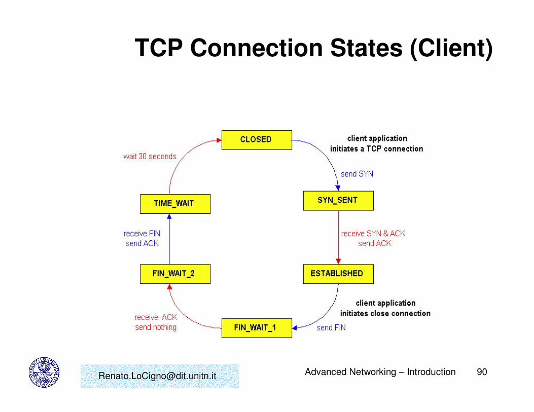
TCP Connection Management
• TCP connection is set up using the three way handshakeprotocol
• Special segments (SYN segment, SYNACK segment) exchange initial client and server sequence numbers and allocate buffers
• Three Way Handshake protocol allows to detect and eliminate “old” connection requests (more robust than two separate handshakes)
• Another Three Way Handshake (with FIN flag turned on) is used to close the connection, releasing all resources