Advanced Communications Technology Satellite High Burst ...
50
NASA Contractor Report 189162 Advanced Communications Technology Satellite High Burst Rate Link Evaluation Terminal Communication Protocol Software User's Guide Version 1.0 Richard C. Reinhart Analex Corporation Brook Park, Ohio March 1993 Prepared for Lewis Research Center Under Contract NAS3-25776 National Aeronautics and Space Administration (NASA-CR-189162) ADVANCED COMMUNICATIONS TECHNOLOGY SATELLITE HIGH bURST RATE LINK EVALUATION TERMINAL COMMUNICATION PROTOCOL SOFTWARE USER'S GUIDE, VERSION 1.0 Final Report (Analex Corp.) 48 p G316I N93-23134 Uncl,_s 0156316
Transcript of Advanced Communications Technology Satellite High Burst ...

NASA Contractor Report 189162
Advanced Communications Technology SatelliteHigh Burst Rate Link Evaluation TerminalCommunication Protocol SoftwareUser's GuideVersion 1.0
Richard C. Reinhart
Analex CorporationBrook Park, Ohio
March 1993
Prepared for
Lewis Research Center
Under Contract NAS3-25776
National Aeronautics andSpace Administration
(NASA-CR-189162) ADVANCED
COMMUNICATIONS TECHNOLOGY SATELLITE
HIGH bURST RATE LINK EVALUATION
TERMINAL COMMUNICATION PROTOCOL
SOFTWARE USER'S GUIDE, VERSION 1.0
Final Report (Analex Corp.) 48 p
G316I
N93-23134
Uncl,_s
0156316

l.d _ T

High Burst Rate Link Evaluation TerminalCommunication Protocol Software User's Guide
Version 1.0, January 1993
Table of Contents
1.0 INTRODUCTION ...................... 1i.i Identification of Document ............ 1
1.2 Scope of Document ................. 1
1.3 Purpose and Objectives of Document ........ 2
1.4 Document Status and Schedule ........... 2
1.5 Document Organization ............... 3
2.0 RELATED DOCUMENTATION ................. 4
2.1 Parent Document .................. 4
2.2 Applicable Documents ............... 4
2.3 Information Documents ............... 4
3.0 OVERVIEW OF PURPOSE AND FUNCTION ............ 6
3.1 Protocol Software History and Overview ...... 63.2 MCP and IFSM Command Files ............ 6
3.3 Event and Telemetry Messages ........... 73.4 Protocol Software Test Procedure ......... 7
3.5 Restrictions and Limitations ........... 8
4.0 INSTALLATION AND INITIALIZATION ............ 9
4.1 Initiation Commands ................ 9
4.2 Equipment Requirements and Set-up ......... I0
4.3 MCP Command File Names ........ . . _ _ _ . II
4.4 Loading System Programs and System Requirements . . 12
5.0 STARTUP AND TERMINATION ................ 13
5.1 Pre-initialization Procedures .......... 13
5.2 Start-up Commands ................. 145.3 Normal Termination Procedure ........... 14
5.4 Abnormal Termination Procedure .......... 15
5.5 Abnormal Restart Procedure ............ 15
6.0 FUNCTIONS AND THEIR OPERATIONS ............. 16
6.1 MCP and IFSM Command Files ............ 16
6.1.1 File Syntax ............... 17
6.1.2 File Size .......... 19
6.3 Sending MCP and IFSM Command Files to the CR&T . . 21
6.4 Protocol Software Monitor ............. 23
6.5 Event Messages .................. 24

7.0 ERRORMESSAGESAND RECOVERYPROCEDURES......... 257.1 MCP and IFSM Command File Syntax Errors ...... 257.2 Protocol Errors .................. 267.3 MCP CommandErrors ................ 277.4 Synchronization .................. 28
8.0 ABBREVIATIONS AND ACRONYMS............... 29
9.0 GLOSSARY ........................ 31
i0.0 APPENDICES ....................... 32Appendix A .................. 32
Common Menu Functions and Features ........ 32
Appendix B "T'r--i'a'em n 1 Definition ............. 34User's ............ 34
Appendix C ....................... 35
Event Messages .................. 35
Appendix D ............. M nit r ...... 39HBR-LET Control and Performance o o Software
Problem Report .................. 39
Appendix E .... ................... 41
Concurrent 3205 Command Summary ......... 41
ii

Figure
6-1
6-2
6-3
7-1
7-2
B-I
D-I
High Burst Rate Link Evaluation Terminal
Communication Protocol Software User's Guide
Version 1.0, January 1993
List of Figures
MCP Command File ...................
IFSM Memory Load Command File .............Protocol Software Monitor ...............
MCP Command File with errors .............
Positive and Negative Event Messages .........
Output Terminal Port and Type Definition .......
HBR-LET Control and Performance Monitor Software
Problem Report ....................
Page
17
18
23
25
27
34
4O
List of Tables
Table
6-1 MCP Command Protocol Filename Generation
Page
....... 20
iii


High Burst Rate Link Evaluation Terminal Communication ProtocolSoftware User's Guide Version 1.0
Advanced Communications Technology Satellite
Richard C. Reinhart
Analex Corporation
3001 Aerospace ParkwayBrook Park, Ohio 44142-1003
1.0 INTRODUCTION
I.i Identification of Document
This is the Communication Protocol Software User's Guide for the
NASA Advanced Communications Technology Satellite (ACTS) High Burst
Rate Link Evaluation Terminal (HBR-LET). This document complies
with the NASA Software Management and Assurance Program (SMAP)guidelines in the Information System Life-Cycle and Documentation
Standards, Release 4.3. This is one component of the Control and
Performance Monitor (C&PM) subsystem document series.
1.2 Scope of Document
The Communication Protocol Software User's Guide contains all the
information needed to load, initialize, and execute the Protocol
Software on a Concurrent 3205 minicomputer. This document assumes
the user is familiar with the Multibeam Communication Package (MCP)
and Intermediate Frequency Switch Matrix (IFSM) commands used tocontrol and configure the ACTS. These commands will not be
discussed in this document in detail, although references arecited.
Users are not required to know the communication packet format usedin the communication protocol. The Protocol Software will assemble
all MCP and IFSM commands into the required format and transmit the
packets to General Electric's (GE) Commanding, Ranging, and
Telemetry Module (CR&T). Users must interpret event messages
returned by the CR&T and take appropriate action when necessary.
Event messages listed in the CR&T/MCS Interface Specification arereproduced in Appendix C of this document for easy reference.
Knowledge of the Concurrent computer user functions is required to
create MCP and IFSM command files. Appendix E contains a summaryof the user commands necessary to create and maintain user files.
Refer to the Multi-Terminal Monitor (MTM) Primer or 0S/32 User's
Manual for additional information on the computer functions.
Communication Protocol Software User's Guide 1
Section i - Introduction
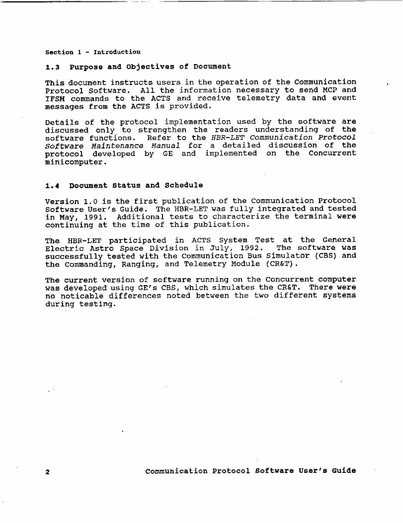
1.3 Purpose and Objectives of Document
This document instructs users in the operation of the Communication
Protocol Software. All the information necessary to send MCP and
IFSM commands to the ACTS and receive telemetry data and event
messages from the ACTS is provided.
Details of the protocol implementation used by the software are
discussed only to strengthen the readers understanding of thesoftware functions. Refer to the HBR-LET Communication Protocol
Software Maintenance Manual for a detailed discussion of the
protocol developed by GE and implemented on the Concurrent
minicomputer.
1.4 Document Status and Schedule
Version 1.0 is the first publication of the Communication Protocol
Software User's Guide. The HBR-LET was fully integrated and tested
in May, 1991. Additional tests to characterize the terminal werecontinuing at the time of this publication.
The HBR-LET participated in ACTS System Test at the General
Electric Astro Space Division in July, 1992. The software wassuccessfully tested with the Communication Bus Simulator (CBS) and
the Commanding, Ranging, and Telemetry Module (CR&T).
The current version of software running on the Concurrent computer
was developed using GE's CBS, which simulates the CR&T. There wereno noticable differences noted between the two different systems
during testing.
2 Communication Protocol Software User's Guide

Section 1 - Introduction
1.5 Document Organization
This document consists of ten sections. Sections 1 and 2 introduce
this document and other documents related to it. Section 3
summarizes the main capabilities, functions, and limitations of theProtocol Software. Initialization requirements to execute the
software are discussed in Section 4. Section 5 outlines the start-
up commands, normal and abnormal termination procedures, and the
recovery procedure from abnormal termination. Section 6 describes
the requirements of the MCP and IFSM command files and the ProtocolSoftware Monitor. MCP and IFSM command file errors, protocol
errors and synchronization are discussed in Section 7. Sections 8and 9 include a list of abbreviations and acronyms used in this
document and a glossary of special terms. Section i0 includes a
description of menu commands and instructions for defining the
user's terminal, a summary of the commands used to sign-on to the
computer and create MCP and IFSM command files and a list of Event
messages from the CR&T/MCS Interface Specification document. Usethe C&PM Software Problem Report Form provided in the appendices to
report errors and erroneous operation.
Communication Protocol Software User's Guide 3

Section 2 - Related Documentation
2.0 RELATED DOCUMENTATION
2.1 Parent Document
None
2.2 Applicable Documents
i. ACTS MCP Command List, LeVine, P.J., General Electric Astro
Division, CMD-2606530, 1988.
2. ACTS MCP Programming and Constraints, Beck, G., General
Electric Astro Division, IDD-PAC-2598605, 1986.
3. CR&T/MCS Interface Specifications, Konrad, D., General
Electric Astro Division, IS-C-3261328, 1989.
4. Communication Protocol Software Maintenance Manual, Reinhart
R., NASA Lewis Research Center, to be published.
5. Communication Protocol Software Test Plan, Reinhart R., May
B., Daugherty E., NASA Lewis Research Center, to be published.
2.3 Information Documents
The following document provides an overview of the HBR-LET Software
system.
. A Software Control System for the ACTS High Burst Rate Link
Evaluation Terminal, NASA Technical Memorandum 105207, NASA
Lewis Research Center, Reinhart, R. and Daugherty, E.,
December, 1991.
Refer to the respective editor reference manual for operating
instructions.
2. 0S/32 EDIT User's Guide, Concurrent Computer Corporation,
1986.
3. MEDIT Users Guide, Perkin Elmer Corporation, 1984.
4. MicroEMACS Reference Manual, Lawrence, D.M. and
Straight, B., 1987.
4 Communication Protocol Software User's Guide

Section 2 - Related Documentation
The following textbook provides an overview of the sliding window
protocol used in the Communication Protocol Software.
5. Computer Networks, Tanenbaum, A., Englewood cliffs, Prentice
Hall, 1981.
Communication Protocol Software User's Guide 5

Section 3 - Overview of Purpose and Function
3.0 OVERVIEW OF PURPOSE AND FUNCTION
3.1 Protocol Software History and Overview
The protocol implemented in the Protocol Software on the Concurrent
3205 minicomputer was initially designed and developed by GE for aHewlett Packard (HP) i000 series computer running the RTE-A
operating system and a DEC VAX computer running the VMS operating
system. Software did not exist for the Concurrent computer andtherefore was developed at the NASA Lewis Research Center according
to the protocol specifications specified by GE.
There are two major functions performed by the Communication
Protocol Software. First, it enables experimenters to send MCP and
IFSM commands to the ACTS spacecraft via GE's CR&T. These commands
control and configure the satellite to a desired configuration for
a variety of applications. Second, it receives telemetry data from
the ACTS and event messages generated by the CR&T.
Two RS-232 serial channels provide a medium for full duplex
communication between the Concurrent 3205 and GE's CR&T. One
channel is responsible for sending data whereas the other is
responsible for receiving data. Synchronization and link
monitoring are built into the protocol. The Protocol SoftwareMonitor discussed in subsequent sections of this document, allows
users to view the activity on both links by displaying the number
and types of packets transmitted and received on the respectivelinks. Refer to the HBR-LET Communications Protocol Software
Maintenance Manual for additional information on the sending and
receiving protocol implementation and format.
3.2 MCP and IFSM Command Files
The Protocol Software enables users to transmit high rate MCP
commands and IFSM commands to the ACTS via GE's CR&T. High rate
MCP commands provide remote control of traveling wave tube
amplifiers, receivers, and other components of various transponderson board the ACTS. The IFSM commands consists of configuration and
memory load commands that alter the state of the Digital Control
Unit (DCU). The DCU which controls the IFSM, provides various
communication paths through the IFSM. Refer to the ACTS MCPCommand List and ACTS MCP Programming and Constraints documents foradditional information on both the MCP and IFSM commands and
technical format.
Develop MCP and IFSM commands according to the format specified inthe above documents in ASCII text files using text editors on the
6 Communication Protocol Software User's Guide

Section 3 - Overview of Purpose and Function
Concurrent computer or any PC word processor. MCP and IFSMcommands transmitted to the ACTS from the LET ground station willbe routed to the CR&T for destination verification and command
validity. The Protocol Software verifies command syntax and
command length only.
Users are responsible for creating and maintaining MCP and IFSM
command files in a private account on the computer system. TheProtocol Software retrieves command files from an account on the
computer system and transmits them to the CR&T. The command filecontains the desired commands and comments. Contact the Concurrent
computer system administrator to gain access to an account on the
system.
3.3 Event and Telemetry Messages
There are two types of event messages described in Appendix C;
broadcast messages and station specific messages. Broadcast event
messages indicate the current status of the CR&T. Station specificevent messages are sent by the CR&T in response to commands
received from a particular station. These messages generallycontain information regarding the status of MCP or IFSM command
packets sent to the CR&T.
In addition to event messages, all stations on the communication
network receive telemetry data from the ACTS via GE's CR&T. The
telemetry data contains information concerning the Communication
Electronics Package on board the ACTS. TWTA current levels,
voltage levels, temperature levels and other information concerning
the bus is provided. Currently, the telemetry data received fromthe CR&T is verified to insure the integrity of the communication
link, and then discarded.
3.4 Protocol Software Test Procedure
A test procedure has been developed to verify the operation of theProtocol Software. The HBR-LET Communication Protocol Test Plan
provides a step-by-step procedure to test telemetry reception,
numeric commanding, event message processing, telemetry error
handing, and command error handling.
Log files generated by the test software records the data received
by the C&PM computer and the responses of the C&PM computer to the
various packets received. Refer to the HBR-LET Protocol Software
Test Plan for specific details concerning each independent test.
Run the Protocol Software test to verify the operation of the
Protocol Software or to identify problems if errors are suspected.
Communication Protocol Software User's Guide 7

Section 3 - Overview of Purpose and Function
GE's CBS was used to develop the test procedure described in the
HBR-LET Communication Protocol Software Test Plan. As future
testing with GE's CR&T occurs, modifications will be made to the
test plan if deemed necessary. The test plan was designed to be
applicable to both the CBS and CR&T. The plan tests for both
normal operation and error conditions of the Protocol Software.
Error forced in the data at known positions tests the error
recovery capabilities of the software. All forced errors in the
test plan are generated by the Concurrent computer, independent of
the receiving node. The Protocol Software developers will verify
the operation of the Protocol Software with the CR&T before makingit available to users.
3.5 Restrictions and Limitations
The Protocol Software constantly receives telemetry data from the
CR&T while it is functioning, and therefore is active at all times
the software is executing. Although the Protocol Software is
designed to minimally impact the computer system, running multiple
programs in addition to the Protocol Software may result in reduced
performance (in terms of execution time) of the other programs due
to processor limitations.
Terminate the Protocol Software when it is not needed to avoid
impacting other applications concurrently running. The software
can be repetitively started and terminated from the C&PM Main Menu.
8 Communication Protocol Software User's Guide

4.0
Section 4 - Installation and Initialization
INSTALLATION AND INITIALIZATION
4.1 Initiation Commands
Three terminals are used to initialize, operate and maintain the
Communication Protocol Software; a user's terminal, a programmer's
terminal and the system console. The user's terminal serves as the
primary user interface to the Protocol Software and other C&PM
software applications. All Protocol Software functions including
initializing the system, monitoring the communication links, and
sending command files to the CR&T are controlled from the user's
terminal by making the appropriate menu selections from the C&PMMain Menu.
The programmer's terminal providesaccess to the computer systemvia a user's account under MTM. Use the programmers terminal to
sign-on to the computer system and to create MCP and IFSM command
files using the text editors installed on the system. The user's
terminal does not provide access to the computer system other than
for specific C&PM software applications.
The system console provides the user with greater control of the
computer system. Use the system console to recover from
catastrophic errors when they occur. Refer to Section 7 for
information on error messages and error recovery.
Execute the Protocol Software from the user's terminal using the
C&PM Main Menu. Appendix A describes the C&PM menu commands used
throughout the Protocol Software. The procedures for selecting a
menu item, inputting data to a menu and navigating through the menu
system are described. The menu commands are the same for all menus
and will not be repeated each time they occur in this document.
The user terminal serial communication port connection on the
computer is defined in the first line of the Protocol Software menu
program. Although a dedicated port has been reserved, the port
designation can be changed if necessary. Appendix B contains a
list of the Protocol Software menu programs and a procedure for
redefining the user's terminal. Use the programmer's terminal to
modify the Protocol menu programs.
Communication Protocol Software User's Guide 9

Section 4 - Installation and Initialization
4.2 Equipment Requirements and Set-up
The Protocol Software resides on a Concurrent Corporation 3205
minicomputer utilizing Concurrent's OS/32 operating system. The
Concurrent computer has a Multi-Terminal Monitor (MTM) in addition
to the operating system, which serves as the interface between the
user and the OS/32 operating system. All programs do not run under
the control of MTM. The Protocol Software does not run under MTM,
and therefore can only be executed from the user's terminal
described in Section 4.1.
Two RS-232 serial communication ports of the Concurrent 3205
minicomputer are utilized to communicate with GE's CR&T. One
channel is dedicated to transmitting data to the CR&T, and the
other channel dedicated to receiving data from the CR&T. Each
cable must be connected to the proper port for the system to
function properly. Failure to meet this requirement will result in
the inability to install or execute the Protocol Software. Referto the HBR-LET Communication Protocol Software Maintenance Manual
for a description of the communication port assignments and a
general description of the hardware set-up. This requirement
should be completed by the Software Manger or someone knowledgeable
of the computer hardware configuration. Report any hardware
configuration problems to the C&PM Software Manager, by completing
the upper half of the CPMPR form provided in Appendix D.
An in-house developed menu driver utilized by the software requires
a WYSE 50 or compatible terminal for best operation. The type of
terminal used for menu display is indicated in the first record of
the Protocol Software menu program. Refer to Appendix B for a
description of the user's terminal definition and a list of the
menu programs associated with the Protocol Software.
10 communication Protocol Software User's Guide

Section 4 - Installation and Initialization
4.3 MCP Command File Names
Filenames on the Concurrent computer will consist of a volume, file
name, extension, and account number employing the following format:
MI: • I###
I ' account number
filename extension
filename
user volume
User volume Two volumes on the Concurrent 3205 computer are
independently utilized by the OS/32 operating
system and individual user applications
respectively. All MCP command data files will be
located on the user volume, MI.
Filename I All filenames on the Concurrent 3205 computer
consist of one to eight alphanumeric characters
with the first being alphabetic. The Protocol
Software uses only the first four characters of the
data file name. Users are permitted to use
additional characters in the name, but note that
the Protocol Software will omit extra characters
when referring to the file. The protocol standard
allows for a six character file name. The Protocol
Software uses the additional characters to properly
identify the data files sent to the CR&T. The user
can select any name for the MCP or IFSM command
data file.
Extension One to three alphanumeric characters indicating anextension to the filename. File name extensions
are permitted, but will be disregarded by the
Protocol Software when referring to the file.
Account number A dedicated user account on the computer system.
User account numbers range from 1 to 254. Contact
the system administrator for proper access to an
account on the computer system.
Communication Protocol Software User's Guide 11

Section 4 - Installation and Initialization
4.4 Loading System Programs and System Requirements
This document assumes that the Concurrent computer has been
successfully booted and the C&PM Software installed and running.
If the C&PM Software is not running, type the following command at
the system console prompt:
> CPM
The computer system will respond with the following message
indicating that the C&PM Software is ready.
C&PM Software System Successfully Loaded and Started
MCP and IFSM command files must exist in a user's private account
before they can be sent to the CR&T. The Protocol Software does
not provide a means to create nor edit command files. Create
command files using the programmer's terminal before executing the
Protocol Software. Contact the system administrator to obtain
access to a private computer account to create command files.
12 Communication Protocol Software User's Guide

5.0 STARTUP AND TERMINATION
Section 5 - Startup and Termination
5.1 Pre-initlalization Procedures
The Protocol Software does not run under the control of MTM. If
both the Protocol Software and MTM are executing simultaneously,
the communication ports connected to GE's CR&T must be removed from
MTM. Remove the communication port by typing the following
commands at the system console prompt:
> REMMTMLET <cr>
Failure to remove the communication ports from MTM will result in
the inability to execute the Protocol Software, Display the
logical unit assignment of the MTM task at the system console to
verify that the communication ports are not assigned to the MTM
task. Enter the following commands:
> T(ask) .MTM
> D(isplay) L(ogical Units)
The computer will respond with a list of the logical unit
assignments and their associated device. Verify that CRT6: and
CRT7: are not on the list. If either device appears on the list,
repeat the above procedure paying close attention to the command
syntax. Notify the C&PM Software Manager if errors persist via a
CPMPR form provided in Appendix D.
Note: This pre-initialization step should be completed by the
C&PM Software Manager or someone knowledgeable of the
computer system when installing the C&PM Software
system. This section is included for completeness.
Communication Protocol Software User's Guide 13
Section 5 - Startup and Termination
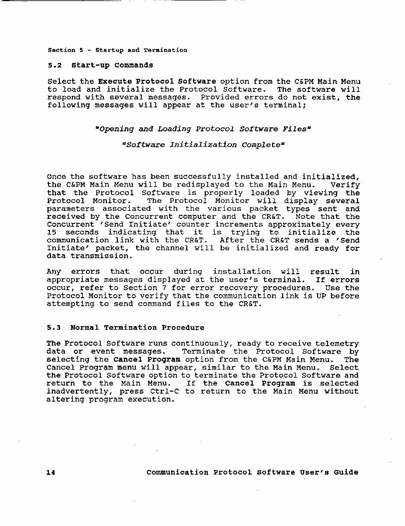
5.2 Start-up Commands
Select the Execute Protocol Software option from the C&PM Main Menuto load and initialize the Protocol Software. The software will
respond with several messages. Provided errors do not exist, the
following messages will appear at the user's terminal;
"Opening and Loading Protocol Software Files"
"Software Initialization Complete"
Once the software has been successfully installed and initialized,
the C&PM Main Menu will be redisplayed to the Main Menu. Verify
that the Protocol Software is properly loaded by viewing the
Protocol Monitor. The Protocol Monitor will display several
parameters associated with the various packet types sent and
received by the Concurrent computer and the CR&T. Note that the
Concurrent 'Send Initiate' counter increments approximately every15 seconds indicating that it is trying to initialize thecommunication link with the CR&T. After the CR&T sends a "Send
Initiate' packet, the channel will be initialized and ready fordata transmission.
Any errors that occur during installation will result in
appropriate messages displayed at the user's terminal. If errors
occur, refer to Section 7 for error recovery procedures. Use the
Protocol Monitor to verify that the communication link is UP before
attempting to send command files to the CR&T.
5.3 Normal Termination Procedure
The Protocol Software runs continuously, ready to receive telemetry
data or event messages. Terminate the Protocol Software by
selecting the Cancel Program option from the C&PM Main Menu. The
Cancel Program menu will appear, similar to the Main Menu. Select
the Protocol Software option to terminate the Protocol Software and
return to the Main Menu. If the Cancel Program is selected
inadvertently, press Ctrl-C to return to the Main Menu without
altering program execution.
14 Communication Protocol Software User's Guide

Section 5 - Startup and Termination
5.4 Abnormal Termination Procedure
In the event the Protocol Software cannot be terminated from the
user's terminal, use the system console to abort program execution.
Enter the following command at the system console to terminate theProtocol Software.
> PROABORT
This command will cancel all the programs associated with theProtocol Software and return the Main Menu to the user's terminal.
This command will also terminate the program that sends command
files to the CR&T. If the command file program (option - Send
MCP/IFSM File) is interrupted, verify that the commands were
received by the CR&T. Resend the commands if necessary to assure
they are received by the CR&T.
5.5 Abnormal Restart Procedure
Reinitialize the Protocol Software after a failure by following the
normal startup commands. Using the Protocol Monitor, verify that
the communication link is operational by observing that the link isUP. If an error condition exists after several initialization
packets are sent, submit a CPMPR form to the C&PM Software Manager.
Communication Protocol Software User's Guide 15

Section 6 - Functions _and their Operations
6.0 FUNCTIONS AND THEIR OPERATIONS
6.1 MCP and IFSM Command Files
MCP and IFSM command files enable users to specify multiple or
single commands to send to the ACTS spacecraft. The data files
provide a convenient and efficient method of documenting the
commands sent to the spacecraft as well as providing users a way to
prepare commands before using the Protocol Software.
The MCP and IFSM command files must exist in a user account on the
Concurrent system before accessing the Protocol Software. Create
command files using any text editor or word processor capable of
reading and writing an ASCII text file.
Use the programmer's terminal to create command files on the
Concurrent computer. Three text editors; EDIT32, EMACS, and MEDIT
are currently installed on the computer system. Refer to the
respective user's manual for operating instructions on the variouseditors.
Note: Errors have occurred in the past using the EMACS editor
to create files due to control characters placed within
the document. If EMACS is used to create files, save the
file using one of the other editors on the system.
EDIT32 and MEDIT do not attach control characters to
their documents.
Save word processing files as "ASCII text files" to eliminate
control characters in the document. Transfer files created using
word processors to the Concurrent computer before using the
Protocol Software.
16 Communication Protocol Software User's Guide

Section 6 - Functions and their Operations
6.1.1 File Syntax
The ACTS MCP Command List lists and describes the valid MCP
commands. The ACTS MCP Programming and Constraints document
describes the format of the IFSM commands. The list of MCP
commands includes the hexadecimal code, type, description, mnemonic
and telemetry information for each command. The Protocol Software
will only read the hexadecimal code for each command from the data
file. All other information concerning a command must be declared
a comment if included in the file. Figure 6-1 illustrates a sample
MCP Command File.
; MCP Command File
50AF ; TWTA NO.I ON
9D62 916E 9966 ; TWTA NO.2 HELIX PROTECT ENABLE,ON,UV/OC ENABLE
#; comment line
; comment line
Figure 6-1 MCP Command File
Although IFSM commands are developed as a binary string, they too
must be specified as a hexadecimal number. Manually, convert the
binary string to its hexadecimal equivalent and enter its result asthe valid command. Place the binary string within the file
preceded by a semi-colon representing a comment. Use the binary
string to document and verify the command in the event of errors.
Communication Protocol Software User's Guide 17

Section 6 - Functions and their Operations
Figure 6-2 illustrates the format of an IFSM command file. Notethe conversion of the binary string to its hexadecimal equivalent,
and the comments used.
; IFSM Command File
; Memory Load 0 word ID=0, op bit valid, switch l&2 open
3000 ; O0 1 i/ 0000/0000/00 00
; Memory Load 1 word ID=0, op bit valid, switch I0 closed
4040 ; 01 0 O/ 0000/0100/00 O0#; comment line
; comment line
Figure 6-2 IFSM Memory Load Command File
MCP and IFSM commands must be valid commands from the ACTS MCP
Command List or the ACTS MCP Programming and Constraints documents.Each valid command must consist of four upper case hexadecimal
characters. Individual or multiple commands per line are
permitted, provided they do not exceed eighty columns. Use a spaceas a delimiter for multiple commands on one line. A semi-colon (;)
indicates a comment statement. Comments can encompass an entire
line or a part of line. Everything in a record after a semi-colon
is interpreted as a comment, including valid MCP and IFSM commands.
Place a pound sign (#) after the final MCP or IFSM command.
Additional text may follow the pound sign provided the text is
preceded with a semi-colon.
The Protocol Software will verify the syntax of the data file
before transmitting it to the CR&T. If a syntax error exist, the
file will not be transmitted and the user notified with appropriate
error messages. Refer to Section 7 for additional information and
recovery procedures from syntax and other command file errors.
18 Communication Protocol Software User's Guide

Section 6 - Functions and their Operations
6.1.2 File Size
MCP and IFSM command files can contain up to 5000 four character
commands. The protocol standard allows a maximum of i00 four
character commands per data packet transmitted to the CR&T from theProtocol Software. The Protocol Software will divide the command
file into the appropriate number of data packets to send to the
CR&T based on the number of commands in the file. Data packet file
names are encoded using the command filename, the account number,
and the current packet number. Use the information in the filename
created by the Protocol Software to identify the location of errors
in the command file, if they occur.
Communication Protocol Software User's Guide 19

Section 6 - Functions and their operations
The protocol standard limits the command filename to six
characters. Although the Protocol Software uses the computer
system filename restrictions (see Section 4.3), the filename
transmitted to the CR&T may differ from the user filename. The
Protocol Software creates the filename as follows:
i• The first four characters of the Protocol filename name are
the first four characters of the user filename.
• The fifth character is the encoded account numberof the file.
The account number is the last character of the actual user
account number.
• The sixth character is the encoded packet number. The packet
number is the last character of the actual packet number•
Table 6-1 lists various examples to illustrate the above procedure•
User
Filename
DEMO.XXX
DEMO2
TESTI
TEST
TEST.TXT
Accnt
Num
5
34
123
147
Number
of
commands
99
98
I01
178
I001
Number of
Packets
1
2
ii
Accnt
Num
5
4
4
3
7
Protocol File;
Num,Name,Command
1 DEMO51 99
1 DEMO41 98
1 TEST41 i00
2 TEST42 1
1 TEST31 i00
2 TEST32 78
1 TEST71 i00
9 TEST79 i00
i0 TEST70 I00
Ii TEST71 1
Table 6-1 MCP Command Protocol Filename Generation
Note: The Protocol Software will use the first four
characters of the user filename. Excess characters and
the filename extension will be disregarded• This
condition will not generate an error message from the
Protocol Software•
20 Communication Protocol Software User's Guide

Section 6 - Functions and their Operations
6.3 Sending MCP and IFSM Command Files to the CR&T
Once an MCP or IFSM command file is created, it is ready to send to
the CR&T. Select the Send MCP/IFSM Command File option from the
C&PM Main Menu (user terminal) to execute the software used to
perform the data transmission function. Perform the followingcommands to successfully transmit a command file to the CR&T.
Computer prompts are illustrated in this text in bold. Press
return after responding to each prompt.
i)
2)
3)
4)
Enter filename:
Enter the command filename at the prompt including the
extension.
Enter Account Number:Enter the account number where the command file resides. The
software will syntax check the filename and verify that the
file exists in the specified account.
Enter Command Destination:
Enter the command destination for the entire command file.
All commands in a single file must go to a single destination.The LET has two valid destinations available; The MCP Command
Enable (CTP) and the IF Switch Matrix Enable. The syntaxcheck on the file contents will occur at this time. Correct
any errors that exist, shown by appropriate error messages,
and repeat the above procedure.
Do you want to send another file with this set(Y/N)?More than one command file can be sent to the CR&T at a time.
Indicate whether to send multiple files or a single file
within the current group. Multiple files will be divided
among separate data packets by the software. A limit of eight
files or 5000 commands (whichever comes first) is imposed bythe Protocol Software. If the file contents exceed the limit,
the software will issue a prompt to determine whether to
transmit the portion of the data packet loaded thus far to theCR&T or abort the session.
Communication Protocol Software User's Guide 21

Section 6 - Functions and their Operations
4a) Responding No (N) to the prompt in step 4 will command the
software to send the specified files to the CR&T. The
Protocol Monitor will display automatically. After a short
pause (5 seconds) the C&PM Command Counter will increment
indicating that the packet(s) have been transmitted to theCR&T. Note that the HPA600 responds with a positive or
negative response packet (ACK or NAK), and the appropriate
counter increments. All event messages are displayed on the
Protocol Monitor as they occur. Verify that all files were
properly received by the CR&T by noting the data packet names
specified in the event messages.
To exit the Protocol Monitor after all packets are sent, press
the return key until a prompt appears indicating to exit or
resume. Press R to Return to the Protocol Software or C to
Continue monitoring.
4b) Responding Yes (Y) will repeat steps 1-4 without sending the
commands specified thus far, provided another file will not
exceed the data packet limit.
5) DO you want to send another file (Y/N)?
This prompt appears after exiting the Protocol Monitor.Indicate whether to send additional files to the CR&T.
5a)
5b)
Responding Yes (Y) will repeat steps 1-5.
Responding No (N) will terminate the MCP/IFSM command file
program and return the C&PM Main Menu to the user terminal.
22 Communication Protocol Software User's Guide

/
Section 6 - Functions and their Operations
6.4 Protocol Software Monitor
Telemetry reception, packet processing, and synchronization are all
performed by the software without displaying output to the user's
terminal. A monitor program enables users to observe the activity
on each link of the Protocol Software. Figure 6-3 illustrates the
menu screen of the Protocol Monitor. A counter for each parameter
is updated on the screen when an action occurs. The time is
provided to monitor the time between data packet transmission and
response packet reception.
Control and Performance Monitoring
Protocol Software Monitor
HP A600 Send Initiate 2
HP A600 Telemetry/Event 134
C&PM Acknowledge Counter 135
C&PM NAK Counter 1
C&PM Send Initiate
C&PM MCP Command
3
17
HP A600 Acknowledge Counter 20
HP A600 NAK Counter 0
Event Messages Received from the HP A600
TWTA92 list received by A600
TWTA92 list verified by A600
Current Time 12:34:56
Figure 6-3 Protocol Software Monitor
Communication Protocol Software User's Guide 23

Section 6 - Functions and their Operations
The parameters of Figure 6-3 represent the number of packets that
are transmitted and received by the C&PM Protocol Software and GE's
HP A600 CR&T. The appropriate counter will increment once for each
packet transmitted or received by the Protocol Software or HP A600,
respectively.
Note: All counters will reset themselves to zero at
approximately 50000 for menu clarity and to avoid
possible overflow.
Telemetry packets and event messages are counted together in the HP
A600 Telemetry/Event counter. Event messages will appear on the
Monitor when they occur. The Protocol Monitor will update the
event message display as new messages are received. The monitor
will automatically appear after sending MCP or IFSM command files
to the CR&T to allow users to verify that the commands were
received and verified by the CR&T. Refer to Appendix C for a list
of the event messages and a description of each.
The CR&T automatically sends telemetry data to all stations on the
network. Telemetry data received by the Protocol Software is not
displayed by the Protocol Monitor. Currently, the HBR-LET does not
use the telemetry data and therefore it is not displayed.
6.5 Event Messages
Event messages are issued by the CR&T and received by the Protocol
Software. Event messages contain information concerning the CR&T
status or information about command files sent to the CR&T from the
Concurrent computer. Event messages occur randomly and each have
different lengths depending on the particular message. Use the
Protocol Monitor to view event messages after sending commands to
the CR&T.
Individual event messages are described in the CR&T/MCS Interface
Specification. A portion of that document has been reproduced in
Appendix C for the user's convenience. Refer to Appendix C for
additional information on specific event messages encountered.
24 Communication Protocol Software User's Guide

Section 7 - Error Messages and Recovery Procedures
7.0 ERROR MESSAGES AND RECOVERY PROCEDURES
7.1 MCP and IFSM Command File Syntax Errors
The Protocol Software will verify the syntax of all commands in theMCP and IFSM command files. MCP and IFSM commands must consists of
four upper case hexadecimal characters 0 through F. If a nonhexadecimal character is detected, the Protocol Software will
display the character(s) in error at the user's terminal. Any MCPor IFSM command that has other than four characters will also be
considered an error. The software will specify the number of extra
characters when this occurs. Figure 7-1 illustrates the two types
of errors discussed above. Comments will not be checked and can
contain any type of character.
50AG
9D62 916E4
#; comment line
; comment line
MCP Command File
; TWTA NO.I ON
; TWTA NO.2 HELIX PROTECT ENABLE, ON
Figure 7-1 MCP Command File with errors
Figure 7-1 is similar to Figure 6-1. Note that the first commandis now 50AG instead of 50AF. The character G in the command will
cause a syntax error because G is not a hexadecimal character. Inthe next line of commands, the second command 916E4 should be 916E.
The syntax check will detect extra or omitted characters (extra inFigure 7-1) and flag the error condition.
Use one of the text editors on the Concurrent computer to edit
command files and recover from syntax errors. Locate the invalid
character(s) in the command file and make the appropriatemodifications to correct the error. The Protocol Software will
recheck the command file before sending it to the CR&T. Repeat the
above procedure if these types of errors persist.
7.2 Protocol Errors
Communication Protocol Software User's Guide 25

Section 7 - Error Messages and Recovery Procedures
7.2 Protocol Errors
Once an MCP or IFSM command file has been properly encoded
according to the CR&T/MCS Interface Specification, it is sent tothe CR&T. The CR&T can acknowledge the packet in one of three
ways. It can send a positive acknowledgement (ACK), a negative
acknowledgement (NAK) or not acknowledge it at all (time out). A
positive acknowledgement indicates successful transmission of the
packet. A negative acknowledgement results when there are protocolerrors in the transmission detected by the CR&T. Failure to send
a response packet of some type represents that the CR&T did notsend a response packet or the Concurrent failed to receive the
response, either of which is an error condition. The ProtocolSoftware will attempt to recover from transmission errors by
sending the data packet again. Data packets not acknowledged bythe CR&T will not return event messages.
If a data packet does not receive a positive acknowledgement afterthree consecutive tries, the Protocol Software will abort the
process and reinitialize the communication link. Users must repeatthe procedure to send a command file to the CR&T if this occurs.
If this type of error persists after several tries, notify the C&PMSoftware Manager. This indicates an error in the communication
link or the protocol software at either the sending or receiving
node.
26 communication Protocol Software User's Guide

Section 7 - Error Messages and Recovery Procedures
7.3 MCP Command Errors
An MCP command data packet received by the CR&T from the Concurrent
computer may still contain errors. The CR&T will verify each
command of the MCP file before sending it to the ACTS spacecraft.If the CR&T detects an invalid command, it will stop transmitting
the commands to the ACTS, and send an event message back to the
Protocol Software indicating the type of error that occurred.
Refer to Appendix C for a list of possible event messages. Use theProtocol Monitor to view event messages after sending an MCP
Command File. Figure 7-2 illustrates both a positive and negative
event message. A positive event message is generated by the CR&Twhen all commands in the data file are valid.
a) Positive Event Message
TEST41 list received by A600
TEST41 list verified by A600
b) Negative Event Message
TEST31 Packet rejected, list contains unauthorized commands
Figure 7-2 Positive and Negative Event Messages
Note that the event message contains the filename generated by the
Protocol Software which may be different from the user filename.Refer to Section 6.1.2 for an explanation of the protocol filename
generation procedure. Positive event messages indicate that the
command packet was received and that all the commands were valid.
Negative event messages indicate that the command packet was
received , but contained at least one invalid command. The CR&T
will not continue to process a packet once an invalid command is
detected. The user is responsible to determine the invalid commandand correct the error.
Communication Protocol software User's Guide 27

Section 7 - Error Messages and Recovery Procedures
7 •4 Synchronization
Both the sending and receiving node are required to send
synchronization packets during periods of link inactivity. TheProtocol Software will send synchronization packets to the CR&T to
initialize the link and during times when no command packets are
sent.
The CR&T will send synchronization packets to the Protocol Softwarewhen there are no event messages or telemetry data to transmit. If
either node fails to send the synchronization packet at the
required intervals, the communication link will become inoperativeuntil reinitialized by both nodes.
Users can monitor the synchronization packets using the Protocol
Monitor. The synchronization or initialization counter will
increment each time a packet is sent or received. If the linkfails for an extended period of time (approximately 1-2 minutes),
notify the C&PM Software Manager, provided the respective protocolsoftware is running at both the sending and receiving nodes.
28 Communication Protocol Software User's Guide

Section 8 - Abbreviations and Acronyms
8.0 ABBREVIATIONS AND ACRONYMS
All abbreviations are defined the first time they appear in this
document. Reference the list of abbreviations and acronyms and
their definition when using this manual.
ABBREVIATION
ACK
ACTS
C&PM
CBS
COMSAT
CPMPR
CR&T
CTP
DEC
GE
HBR-LET
HP
MCP
MCS
MTM
NAK
NASA
DEFINITION
Positive acknowledgement
Advanced Communications _echnology Satellite
Control and Performance Monitoring
Communications Bus Simulator
Communications Satellite Corporation
Control and Performance monitoring Problem
Report Form.
Commanding, Ranging, and Telemetry Module
Command and Telemetry Processor
Digital Equipment Corporation
General Electric
High Burst Rate Link Evaluation Terminal
Hewlett Packard
Multibeam Communication Package
Master Control Station
Multi-Terminal Monitor
Negative acknowledgement
National Aeronautics and Space Administration
Communication Protocol Software User's Guide 29

Section 8 - Abbreviations and Acronyms
PROSA
RTE-A
SMAP
VAX
VMS
Protocol Software Account, Volume MI, account
number 5
Run-time executive, version A
Software Management and Assurance Program
Virtual Addressing Extension
Virtual Memory System
30 Communication Protocol Software User's Guide
9• 0 GLOSSARY
section 9 - Glossary
event message - status or information messages of random packet
sizes sent by the CR&T to receiving stations on the link.
MCP command - various control commands to configure the ACTS.Commands are used to control the Motor Drive Electronics,
Intermediate Frequency Switch Matrix and the Baseband Processor.
response packet - the receiving node sends this type of packet to
the sending node to indicate the status of the received packet.
Response Packets can be positive or negative acknowledgements
depending on the status. Negative acknowledgements result in
retransmitting the original packet from the sending node until
successful reception (ACK) or three consecutive attempts.
synchronization - both stations on the communication link are
required to send special packets across the channel during periods
of inactivity to assure that the channel is ready for the next
transmission. The synchronization packets place the receiving
nodes in a known state, ready for future transmissions.
telemetry packets - data received from the satellite and
transmitted to all stations on the network. These packets are
transmitted at a constant rate and packet size.
Communication Protocol Software User's Guide 31

Appendix A - Common Menu Functions and Features
I0o 0 APPENDICES
Appendix A
Common Menu Functions and Features
There are several functions common to all menus found in the C&PM
Subsystem Protocol Software. These functions are presented indetail and later summarized for easy reference. The key stroke and
resulting action are both listed in the summary.
Data can be input to a menu using a combination of two ways. Thefirst is to type the desired data in a format identical to that
given in the option field for the particular input. Numerical
values are generally typed in and do not have any special format.Both decimal and integer numerical values are accepted. It is best
to clear the input field before entering any typed input. Clear
the input field by either pressing the space bar over each
character or by pressing the DELETE key, which will clear theentire field.
The second method of entering data is by selecting an element of
the option field. To select an option, first move the cursor into
the option field by pressing the HOME key. Placing the cursor on
the same line as the desired option and pressing the ENTER key will
place a copy of the option and the cursor into the input field.
Repeat the above steps until all selections are made. Once inside
the input field, press ENTER a second time to direct the system to
accept the input.
If a mistake is detected after the system has accepted an input,
the user can return to the previous menu by pressing CTRL-C.
However, this will not reverse the previous command. Be certain
the current menu has not been altered in any way prior to pressing
CTRL-C. If the menu has been altered, pressing CTRL-C is
equivalent to pressing ENTER. CTRL-C can only be used before any
change is made in the current menu.
Some menus contain more than one input field. The above procedures
can be followed for each input field. Use the arrow keys or the
tab key to move from one field to another, and the arrow keys to
move among the various options in the option field.
Note: CAPS LOCK key must be on during all menu functions to
ensure proper menu operation.
32 Communication Protocol Software User's Guide

ENTER:
HOME:
DELETE:
CTRL-C:
ARROW
KEYS:
TAB:
Appendix A - Common Menu Functions and Features
Summary of Commands
Once the input field contains a selection, this command
will instruct the system to accept the input.
Toggle the cursor between the input and option fields.
Clears the entire input field that the cursor currentlyresides in.
Allows the user to 'back out' of the menu system one
menu each time it is pressed. Equivalent to pressing
ENTER if menu is altered prior to using this function.
Used to move among the options and input fields.
Used to move among the input fields.
Communication Protocol Software User's Guide 33

Appendix B - User's Terminal Definition
Appendix B
User's Terminal Definition
This section is included in the event it is necessary to change the
location of the menu output. The user terminal used for menu
output is defined in the menu software. The menu software consists
of several files used by the menu driver for menu display. It is
important when defining a new user terminal location not to alter
any of the menus within the file. Changes in any menu may cause "
the software to fail.
The menu software of the Protocol Software consists of the file
PROTOCOL.MNU, located in the Protocol Software Account (PROSA).
Both the terminal type and the communication port is defined in the
first record the file. The communication port definition begins in
column 31, and the terminal type in column 40. An example in
Figure B-I is given using the dedicated port assignment. Only the
first record of the file is shown.
1 2 3 4 5 6 812345678901234567890123456789012345678901234567890123456789012345...0
CRT2: 50
Figure B-I Output Terminal Port and Type Definition
In Figure B-I, CRT2: refers to the communication port currently
dedicated to menu output, while the 50 refers to the WYSE 50
terminal type. In most circumstances the terminal type will remain
50. For other valid inputs, refer to the MENUP menu driver
documentation. The communication port defined for menu output must
be removed from MTM (.MTM REM CRT2:) if it is running
simultaneously with the Protocol Software.
Change the Protocol Software menu program using the EDIT32 lineeditor or the MEDIT screen editor installed on the Concurrent
computer. Using EMACS to edit the menu file will result in
erroneous displays and software failure. Refer to the respective
editor documentation for user instructions.
34 Communication Protocol Software User's Guide

Appendix C - Event Messages
Appendix C
Event Messages
Appendix A of the CR&T/MCS Interface Specification document is
included in this guide for the users convenience. The CR&T/MCS
Interface Specification document provides information on various
event message formats and command types (Low Rate/High Rate). The
reader is encouraged to consult the CR&T/MCS Interface
Specification document for additional information. The following
is a list of possible event messages.
These types of messages shall be broadcast to all stations each
time they occur.
Event Message Explanation
Bad FCD command counter
status
The FCD error status bit in telemetry is
set.
CR&T awaiting command
packets
The CR&T is able to accept high-rate
command packets from all stations. This
message is typically transmitted
following CR&T module initialization and
upon clearing an error.
Resynchronizing the FCDcounter
The CR&T is synchronizing the high-ratecommand counter with that received in
telemetry. This will occur during
initialization and in response to a
directive from the Flight System Monitor
and Control.
Beginning TLM The CR&T has begun to receive telemetry
from the spacecraft.
TLM Lost The CR&T is no longer receiving telemetry
from the spacecraft.
Communication Protocol Software User's Guide 35

Appendix C - Event Messages
This group of messages contain a file name in the first six bytes
of the message. These messages shall only be transmitted to the
source station.
Event Message Explanation
FILENAME - Packet rejected, listhas more than i00 command words.
The command packet contains more
than i00 command words and was
therefore rejected by the CR&T
module.
FILENAME - Packet rejected, list
has more than i0 discrete.
The command packet contains more
than i0 discrete and was
therefore rejected by the CR&T
module.
FILENAME - Packet rejected, CR&T
is in local mode.
The command packet was received
by the CR&T module while the CR&Tmodule was in the local mode.
FILENAME - Command list rejected
by CR&T.
The command packet was received
by the CR&T module, but high-rate
commanding has been disabled by
the CR&T software.
FILENAME - List received by the
CR&T.
The CR&T module received the
command packet.
FILENAME - Packet rejected, Packet The packet command count differs
count not equal to number of from the actual number of
commands received, commands received in the packet.
FILENAME - Packet rejected, list
contains unauthorized commands.
The command list received
contains one or more protectedcommands which have not been
authorized.
36 Communication Protocol Software User's Guide

Appendix C - Event Messages
Event Message Explanation
FILENAME - List verified by CR&T. The CR&T module has verified that
the command list has been
accepted by the spacecraft FCD.
FILENAME - List verification
failed on command word NNN.
The FCD counter has not updated
sufficiently within the allowable
time window. NNN is the number of
the first command word in the
list that was not accepted.
FILENAME - Successful loopbackverification.
Commands received at the
demodulator matched the commands
sent to the modulator.
Communication Protocol Software User's Guide 37

Appendix C - Event Messages
Event Message Explanation
FILENAME - Loopback verificationfailed on command word NNN.
Commands received from the
demodulator did not match the
commands sent to the modulator.
NNN in the message will appear as
the number (i.e. position in the
list) of the command word thatcaused the failure.
FILENAME - High-rate modulatorstatus error detected.
The modulator has reported an
internal error. The status of the
modulator is observed following
the transmission of a high-ratecommand list and a modulator
reset has been initiated by theCR&T module.
FILENAME - High-rate demodulatorstatus error detected.
The demodulator has reported an
internal error. The demodulator
status will only be checked if
command loopback has been
selected.
FILENAME - Packet rejected due to
station lockout.
The CR&T has locked out the
source station by request of the
FSM&C. The CR&T will not accept
any packets from that station.
38 Communication Protocol Software User's Guide

Appendix D - C&PMSoftware Problem Report Form
Appendix D
HBR-LET Control and Performance Monitor Software Problem Report
Problems or errors may be encountered while executing the Protocol
Software that have not been described within this document. The
user may be able to correct these errors by following the error
recovery procedures discussed in Section 7. If error recovery is
not possible, complete the upper half of the CPMPR form and submit
it to the C&PM Software System Manager.
Recording new or unusual errors encountered while operating the
Protocol Software will assist the software developers in improving
the operation of the software and updating the Protocol Software
User's Guide. A copy of the C&PM Software Problem Report form is
provided in Figure D-I. Submit additional pages if additional
space is needed.
Return the completed CPMPR form to:
Mr. Edward J. Petrik
NASA Lewis Research Center
Mail Stop 54-8
21000 Brookpark Road
Cleveland, Ohio 44135
Communication Protocol Software User's Guide 39

Appendix D - C&PMSoftware Problem Report Form
HBR-LET Control and Performance Monitor Software Problem
Name :
Address :
C&PM Software Application Name:
Feature / Problem Description:
Date:
Organization:
Phone:
(Include sequence number and/or instrument)
Error Messages:
Target Completion Date:
Priority: High Medium Low
Cause of Problem / Action:
Name: Date Corrected:
CPMPR Number:
Figure D-I HBR-LET Control and Performance Monitor Software
Problem Report
40 Communication Protocol Software User's Guide

Appendix E - Concurrent Command Summary
Appendix E
Concurren_ 3205 Command Summary
Appendix E provides a quick reference to assist those user's not
fully knowledgeable of the available commands on the Concurrent
3205 minicomputer. This is only a summary of the frequently used
commands. The user is urged to consult the MTM Primer User's Guide
for further information on the following commands. The full name
of the commands are given. Only the characters outside the
parentheses need be entered at the user terminal.
SIGNON Enables a user to access a private account.
to an account, enter the following:
To sign on
S(IGNON) USER ID,ACCOUNT NUMBER,PASSWORD
The user id is a user defined, one to eight character
name. The account number and password are previously
established by the system administrator for a givenaccount. If this information is required notify the C&PM
Software manager.
SIGNOFF Ends a user session.
SIGNOFF
DISPLAY
FILESDisplays Files in the user's account to the terminal.
Outputs each filename and additional information
identifying each file. Specific files can be displayed
by the use of wildcards (-) when specifying filenames.
Several examples are provided:
D (ISPLAY) F (ILES) Displays all files in account
D F, -.TDF Displays all files with extension.TDF
D F, EXAMPLE.- Displays all files with the name
EXAMPLE regardless of the extension.
Communication Protocol Software User's Guide 41

Appendix E - Concurrent Command Summary
COPYA Used to make a copy of a file in a private account.
Ensure that the name of the file to be created does not
currently exist in the account before executing the copy
command. The copy command will over write the existingfile.
COPYA NAME.EXTENSiON,NEW NAME.EXTENSION
RENAME Changes the name of an existing file in a user's account.
REN(AME) NAME.EXTENSION,NEW NAME.EXTENSION
DELETE
EDIT32
Permanently removes a file from a private account. The
user is advised to exercise caution when deleting filesin the account. Files removed from an account cannot be
recovered.
DEL (ETE) NAME. EXTENSION
Line text editor available on the Concurrent computer.
Use the line editor to create and modify MCP and IFSM
command files. This editor does not place controlcharacters into a document.
EDIT NAME.EXTENSION
Refer to the EDIT32 user's guide for commandinstructions.
MEDIT Screen text editor available on the Concurrent computer.
Use the screen editor to create and modify MCP and IFSM
command files. This editor does not place controlcharacters into a document.
M(EDIT) NAME. EXTENSION
Refer to the MEDIT user's guide for command instructions.
42 Communication Protocol Software User's Guide

EMACS
Appendix E - Concurrent Command Summary
Screen text editor available on the Concurrent computer.
Use the screen editor to create and modify MCP and IFSM
command files. This editor places control characters
into a document. Save the document using one of theother editors described above to remove all control
characters from the document.
E (MACS) NAME.EXTENSION
Refer to the EMACS user's guide for command instructions.
Communication Protocol Software User's Guide 43

Form Approved
REPORT DOCUMENTATION PAGE OMBNo.0704-0188P'ublicrepodingburden Ior this collectionof Informationis estimated to average 1 hourper response, includingthe time for reviewinginstructions,searchingexisting data sources,gatheringe.r¢.l,maintsinin_lthe data needed, ar_l.corn,pie!Insand reviewingthe collectionof information. Send commentsregardingthis burdenestimate or any other aspect of thiscollectionOlinxormatlon,inc=uomgsuggestions mr reouc_ngthis burden,to WashingtonHeadquartemServices, Directoratefor information Operationsand Reports, 1215 JeffersonDavis Highway,Suite 1204, Arlington,VA 22202-4302, and to the Off'K:eof Managementand Budget, Paperwork ReductionProject (0704-0188), Wasldr',gton,DC 20503.
1. AGENCY USE ONLY (Leave blank) !2. REPORT DATE
March 1993
4. TITLE AND SUBTITLE
Advanced Communications Technology Satellite High Burst Rate LinkEvaluation Terminal Communication Protocol Software User's Guide
Version 1.0
6. AUTHOR(S)
Richard C. Reinhart
7. PERFORMING ORGANIZATION NAME(S) AND ADDRESS(ES)
Analex Corporation
3001 Aerospace Parkway
Brook Park, Ohio 44142-1003
9. SPONSORING/MONITORINGAGENCYNAMES(S)ANDADDRESS(ES)
National Aeronautics and Space AdministrationLewis Research Center
Cleveland, Ohio 44135-3191
3. REPORTTYPEANDDATESCOVERED
Final Contractor Report
5. FUNDING NUMBERS
WU-679-50-0A
C-NAS3-25776
8. PERFORMING ORGANIZATION
REPORT NUMBER
E-7657
10. SPONSORING/MONITORINGAGENCY REPORT NUMBER
NASA CR-189162
11. SUPPLEMENTARYNOI"ES
Project Manager, Ernie W. Spisz, ACTS Project Office, (216) 433-3540.
12s. DISTRIBUTION/AVAILABILITY STATEMENT
Unclassified - Unlimited
Subject Category 61
12b. DISTRIBUTION CODE
13. ABSTRACT(Maximum200 words)
The Communication Protocol Software was developed at the NASA Lewis Research Center to support the Advanced Communica-tions Technology Satellite High Burst Rate Link Evaluation Terminal (ACTS I-1BR-LET). The HBR-LET is an experimentersterminal to communicate with the ACTS for various experiments by government, university, and industry agencies. The Communi-
cation Protocol Software is one segment of the Control and Performance Monitor (C&PM) Software system of the HBR-LET. TheCommunication Protocol Software allows users to control and configure the Intermediate Frequency Switch Matrix (IFSM) onboard the ACTS to yield a desired path through the spacecraft payload. Besides IFSM control, the C&PM Software system is alsoresponsible for instrument control during HBR-LET experiments, uplink power control of the HBR-LET to demonstrate poweraugmentation during signal fade events, and data display. The Communication Protocol Software User's Guide, Version 1.0
(NASA CR-189162) outlines the commands and procedures to install and operate the Communication Protocol Software.Discussed in the document are configuration files used to control the IFSM, operator commands, and error recovery procedures.The Communication Protocol Software Maintenance Manual, Version 1.0 (NASA CR-189163, to be published) is a programmer'sguide to the Communication Protocol Software. This manual details the current implementation of the software from a technical
perspective. Included is an overview of the Communication Protocol Software, computer algorithms, format representations, andcomputer hardware configuration. The Communication Protocol Software Test Plan (NASA CR-189164, to be published) provides
a step-by-step procedu/e to verify the operation of the software. Included in the Test Plan is command transmission, telemetryreception, errordetection and errorrecovery procedures.
14. SUBJECTTERMS
ACTS; HBR-LET; Computer software; RS-232 protocol; Satellite ground station; IFswitch matrix; Microwave switch mode (MSM)
17. SECURITY CLASSIFICATION
OF REPORT
Unclassified
18. SECURITY CLASSIFICATIONOF THIS PAGE
Unclassified
NSN 7540-01-280-5500
19. SECURITY CLASSIFICATIONOF ABSTRACT
Unclassified
15. NUMBER OF PAGES
4518. PRICE CODE
A0320. LIMITATION OF ABSTRACT
Standard Form 298 (Rev. 2-89)
PreserVed by ANSI Std. Z39-18298-102