ADl-P00fl3 620 G. AD-P03
24
2-1 0 - ADVANCES IN SRAPDOWsN SENSORS ADl-P00fl3 620 Paul G. Savage 0 AD-P03 620President Strapdown Associates, Inc. Woodbridge Plaza, Suite 150 10201 Wayzata Blvd. Minnetonka, Minnesota 55343 *e - SUMMARY This paper reviews the advances that have taken place in strapdown sensor technology since 1978. It is intended aa an update to the paper on Strapdown Sensors presented as part of AGARD Lecture Series 95 in 1978 ý. Principal areas addressed in strapdown gyro technology are the state-of-the-art in mainstream floated rate-integrating and tuned-rotor strapdown gyros, performance advances in laser gyros, special design considerations - associated with mechanically dithered laaer gyros, the state-of-the-art in magnetic mirror and multioscillator laser gyros, present and projected application areas 1or laser gyros related to size, performance and cost, the theory of operation and state-of-the-art in fiber-optic rate sensor technology, and the 2undameatal distisctions betw-en the laser gyro and fiber-optic rate sensor. Basic areas addressed in atrapdown acc-aleromete:, technology aze performance adances in pendulous ac"ale'ometers, and tho theory of operation and . state-of-the-ar•' ia vibratitg beam accelerometer technology.... * 1. INTRODUCTION The state-of-the-art in strapdown sensor technology has advanced con0,derably since 1978, particulary in the higher accuracy performance categories. Ping laser gyros designed by several manufacturing groups have demonstrated their ability to meet the requirementsar to- I nfaph inertial navigation. LAser gyros are now in operational use on several mejor . aircraft programs, and have demonstrated rallabilities in the field that are exceeding user "goals. Advancel devtlopmant programs have been initiated t.• extend the performance capabillties of the ring laser gyro into the claso needed for 0.1 namh navigation. Conventional floating rate-integrating and tuned-rotor gyro technology has boen iiceauingly applied in the mocerate to low l r-orn•oco strapdown arata. Thesb instruments continue to provide a good alternative to the ring laser gyro in applications requiring .mall size and low cost, whore lower parformance is acceptable. A hew optical tatt Genson o.. technology bahsed on tbo use of fiber-opdics has emerged over the pbst few years as a lower *icot/readfced performance alternative to the ring laser gyro. Simultaneously, ring laser gyro davelopment activities save been directed at cost and itoe reducu.xon to extend its applicability range into the moderate performance areas. Strapdown accelerometer technology continues to be principally based on the pendulous electrically ocrvoed accalernmeter deaign apiroach, Ilesign refinements Aince 1978 have upgraded the pe::formvce of this instrument and somewhat reduced its coat. It continues to . ramAin coatible in cobt and performance with require~mnts in moet etrapdown application areas (In proportiOn to ths cost of the gyro and comtuting elements that are alto contained in a strapdown system). To moet cost targets for the future, a vibrating beam accelerometer technology Ls bcing developed at a lower cost alternative to the pendulous accelerometer. Thio peper reviews each of the instruments diacussed above, with emphasis on the per- fortmance capabiLites, proulem areas, and applications where they have been used or planined for use since 1978, Por each instrument, a brief discuasion is also included which describes its principal of operation. Analytieal descriptions and dotailed design consid- arationa for the float*d rate-inteqrating gyro. tuned-rotor gyro, ring laper gyro, and penduloug acceltrometor have bearn irmvided in the AGARD Lecture Seriew 95 paper on Strspdown Sensors (1), and are not repeated here. trror characteristics for the fiber-optic rate sensor and vibrating bewa accelerometer are proecntsd, hit from a qualitative standpoint. * because the purformance characteristics of these lovices have not been sufficiently dis- 0losed in the open I'Lerature to allow detailed accurate analytical modeling that accounts for the import~nt critical error sources, particularly thosoe that are envirolwantally inducod and which change over time and operating cycles. A qsatiu'alized error budget is also provided for reference at the beginning of the paper which attempts to nesine typical gyro and acceleromtor perfort-anco requirement:! for four types of strapdmwn inertial systems. 2. SR,491OR PR1tF0*ACE REQUIREMENTS
Transcript of ADl-P00fl3 620 G. AD-P03

2-1 0 -
ADVANCES IN SRAPDOWsN SENSORS
ADl-P00fl3 620 Paul G. Savage 0AD-P03 620President
Strapdown Associates, Inc.Woodbridge Plaza, Suite 150
10201 Wayzata Blvd.Minnetonka, Minnesota 55343
*e -
SUMMARY
This paper reviews the advances that have taken place in strapdown sensor technologysince 1978. It is intended aa an update to the paper on Strapdown Sensors presented as partof AGARD Lecture Series 95 in 1978 ý. Principal areas addressed in strapdown gyrotechnology are the state-of-the-art in mainstream floated rate-integrating and tuned-rotorstrapdown gyros, performance advances in laser gyros, special design considerations -associated with mechanically dithered laaer gyros, the state-of-the-art in magnetic mirrorand multioscillator laser gyros, present and projected application areas 1or laser gyrosrelated to size, performance and cost, the theory of operation and state-of-the-art infiber-optic rate sensor technology, and the 2undameatal distisctions betw-en the laser gyroand fiber-optic rate sensor. Basic areas addressed in atrapdown acc-aleromete:, technologyaze performance adances in pendulous ac"ale'ometers, and tho theory of operation and
. state-of-the-ar•' ia vibratitg beam accelerometer technology....
* 1. INTRODUCTION
The state-of-the-art in strapdown sensor technology has advanced con0,derably since1978, particulary in the higher accuracy performance categories. Ping laser gyros designedby several manufacturing groups have demonstrated their ability to meet the requirementsar to-I nfaph inertial navigation. LAser gyros are now in operational use on several mejor .aircraft programs, and have demonstrated rallabilities in the field that are exceeding user"goals. Advancel devtlopmant programs have been initiated t.• extend the performancecapabillties of the ring laser gyro into the claso needed for 0.1 namh navigation.
Conventional floating rate-integrating and tuned-rotor gyro technology has boeniiceauingly applied in the mocerate to low l r-orn•oco strapdown arata. Thesb instrumentscontinue to provide a good alternative to the ring laser gyro in applications requiring.mall size and low cost, whore lower parformance is acceptable. A hew optical tatt Genson o..technology bahsed on tbo use of fiber-opdics has emerged over the pbst few years as a lower
*icot/readfced performance alternative to the ring laser gyro. Simultaneously, ring lasergyro davelopment activities save been directed at cost and itoe reducu.xon to extend itsapplicability range into the moderate performance areas.
Strapdown accelerometer technology continues to be principally based on the pendulouselectrically ocrvoed accalernmeter deaign apiroach, Ilesign refinements Aince 1978 haveupgraded the pe::formvce of this instrument and somewhat reduced its coat. It continues to .ramAin coatible in cobt and performance with require~mnts in moet etrapdown applicationareas (In proportiOn to ths cost of the gyro and comtuting elements that are alto containedin a strapdown system). To moet cost targets for the future, a vibrating beam accelerometertechnology Ls bcing developed at a lower cost alternative to the pendulous accelerometer.
Thio peper reviews each of the instruments diacussed above, with emphasis on the per-fortmance capabiLites, proulem areas, and applications where they have been used or planinedfor use since 1978, Por each instrument, a brief discuasion is also included whichdescribes its principal of operation. Analytieal descriptions and dotailed design consid-arationa for the float*d rate-inteqrating gyro. tuned-rotor gyro, ring laper gyro, andpenduloug acceltrometor have bearn irmvided in the AGARD Lecture Seriew 95 paper on StrspdownSensors (1), and are not repeated here. trror characteristics for the fiber-optic ratesensor and vibrating bewa accelerometer are proecntsd, hit from a qualitative standpoint.
* because the purformance characteristics of these lovices have not been sufficiently dis-0losed in the open I'Lerature to allow detailed accurate analytical modeling that accountsfor the import~nt critical error sources, particularly thosoe that are envirolwantallyinducod and which change over time and operating cycles.
A qsatiu'alized error budget is also provided for reference at the beginning of the paperwhich attempts to nesine typical gyro and acceleromtor perfort-anco requirement:! for fourtypes of strapdmwn inertial systems.
2. SR,491OR PR1tF0*ACE REQUIREMENTS

2-2
areas: the classical 1 nmph inertial navigator, a higher performance advanced 0.1 umphinertial navigator, a lower performance strapdown attitude heading reference system (AHRS),and a still lower performance tactical missile midcourse guidance system. The performancecategories depicted in Table 1 are considered typical for most strapdown sensor applicationstoday and in the immediate future. Table 1 should be used as a reference to categorize
m* typical sensor performance requirements during discussions on individual sensorcapabilities. •
•. TABLE 1 - TYPICAL STRAPDOWN SENSOR PERFORMANCE REQUIREMENTS
Tactical..
0.1 1.0 Missilenmph nmph Midcourse
Performance Parameter INS INS AHRS Guidance
Gyro Bias Uncertainty (deg/hr) 0.001 0.01 1.0(0.1)* 5 to 30
to 10
Gyro Random Noise (deg/hrk)** 0.005 0.002 0.01 0.1
Gyro Scale-Factor Uncertainty (ppm) 1 5 200 1000
Gyro Alignmant Uncertainty (are sec) 1 2 200 300
Acceleromuter Bias Uncertainty (pg) 10 40 1000 1000
Accelerounter Scale-Factor -Uncertainty (ppm) 50 200 1000 1000
Accelerometer Alignment Uncertainty(eec) 2 7 200 300
Accelerometer Bias Trending (Pg/sec! 0.003 0.0; NWIO.1) NA
For AMRS with an earth rate gyro-compass heading detarminetionrequiremesit. Other figure shown ia for AMP5 with hedingslaved to magnetic flux heading detector.
" T'ia error sourve in a ch aotes'iit..c princip•.ly of laser gyros.
3. SINGLE-DEGREE-OP-PREEDOM FLOATED PATE-INTEGRATING GYRO
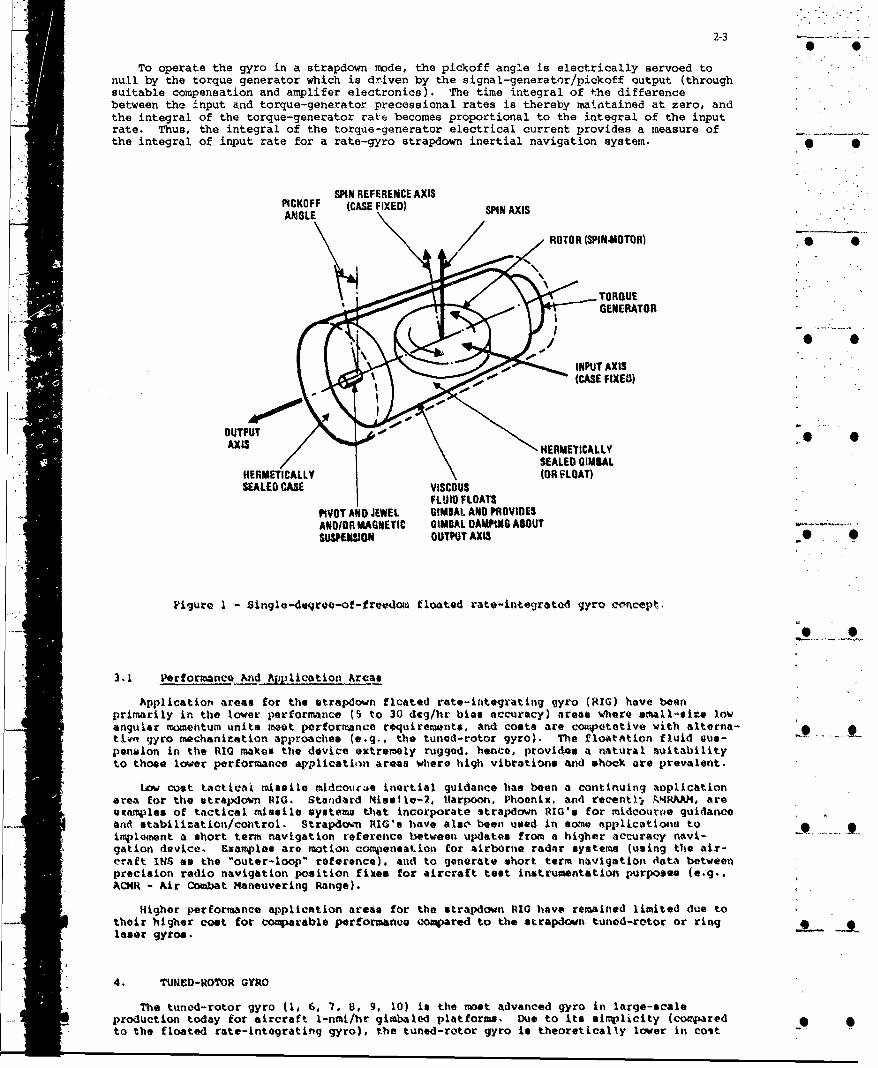
The floated rate-integrating gyro (1, 4, 5) pictured schematically in Pigure I is thegyro with the longest production history and is tho original high-accuracy girnbaled-platformgyro. The device consists of a cylindrical hermetically sealed momentum-wheel/epinmotorassembly (float) contained in a cylindrical hermetically sealed case. The float is inter-faced to tile c44o by A procisiora suspendiOI' assarobly that is laterally rigid (normal to thecylinder axis) but allows .frictionlesio angular movement of the float relative to the caseabout the c'linder axis. 'lhe cavity between the case and float is filled with a fluid that"ervaes the dual purpose of suspending the float at neutral buoyancy, and providing viscouseamvioe te revist relative float-cast angular motion about the autpensical axis.
A ball-bearing or gas-b*aring synohronous-hyateris spinmotor is utilized in the float tomaintain c(nstant rotor spinspmed. hence constant float angular momentum. A signal-generator/pickoff provides an electrical output signal frem the gyro proportional to theangular displacement of the float relative to the case. An electrical torqut genoritorprovides the capability for applying known torques to the float about the sispension axisproportional to an applied electrical input current. Delicate flea leads are used totranmmit electrical sigtAls and power between the case and float.
.eUnder "aplied angular rates atout the input axis, the gyro float devolups a precessionalrate about the oetput axis (rotattlon rate of the angle sensed by the sirtnsi-9%n rator/pick-of , see •igure I). The pickoff-angle rate generates a viscous torque on the float about• • the outrw~t axis (due to the darqping fluid) which aums with the electrically applied
torque-gsnerator torque to precass the float about the input axis at the qyro input rate.The pickoff-angle rate thereby becomes proportional to the difference between the input rateand the torque-generator precessional rate, hence, the pickoff angle bercomes proporti Xonl tothe integral of the difference between the input and torque-generatzr rates.
2-3
To operate the gyro in a strapdown mode, the pickoff angle is electrically servoed tonull by the torque generator which is dr.iven by the signal-generator/pickoff output (throughsuitable compensation and amplifer electronics). The time integral of the differencebetween the input and torque-generator precessional rates is thereby maintained at zero, andthe integral of the torque-generator rate becomes proportional to the integral of the inputrate. Thus, the integral of the torque-generator electrical current provides a measure ofthe integral of input rate for a rate-gyro strapdown inertial navigation system.
SPIN REFERENCE AXISPICKOFF (CASE FIXED) SIN AXIS
ROTOR (SPIN.MOTOR')S/TORQUE
GENERATOR
"• ~INPUT AXIS(CASE FIXED). .*e -
OUTPUTAXIS HERMETICALLY
S EALED GIMBALHERMETICALLY (OR FLOAT)SE.ALED CASE viscous
FLUID FLOAT$
PIVOT AND JEWEL GIMIAL AND PROVIDESAND/OR MAGNETIC GIMBAL DAMI4NG ABOUTSUSPEIIION OUTPUT AXIS• .
Pigure I - Single-degree-of-freedom floated rate-integratod gyro concept.
3.1 Performance Xnd Aplication Areas
Application areas for the strapdown ficated rate-integrating gyro (RIG) have be•etprimarily in the lower performance (5 to 30 degfhr bias accuracy) areas whert small-size lowangular mometitum units teot performance requirements, and coots are cowpotative with alterna- *tiwn gyro mechanitation approaches (e.g.. the tunod-rotor gyro). The floatation fluid aus-penuion in the RIG makes the device extremely rugged, hence, provides a natural euitabilityto those lower performance application areas where high vibration* and shock are prevalent.
Low cost tactica1 missile midcourae inertial guidaivce laos been a continuing aoplicationarea for the st raixlown RIO. Standard Missile-2, tharpoon, Phoenix, and recentl) .k4RAAM, areoxarqples of tactical missile systems that incorporate strapdown RIG's for midcouroe guidanceand stabilization/control. Strapdown RIG'@ have alse been used in some applicatiomi toimplement a short term navigation reference between updates from a higher accuracy navi-gation device. Examples are motion com)ensation for airborne radar systems (using the air-craft INS as the "outer-loop' reference). and to gOnerate short term navigation Oata betweenprecision radio navigation position fixes for aircraft test insttrumentation purposes (e.g.,ACNR - Air Combat Maneuvering Range).
Higher performance application areas for the strapdown RIG have remained limited due totheir higher coat for comparable performance compared to the strapdown tuned-rotor or ring * -laser gyros.
4. TUNED-ROTOR GYRO
The tuned-rotor gyro (1. 6. 7, 8. 9, 10) is the most advanced gyro in large-scaleproduction today for aircraft l-nmi/hr gimbaled platforms. Due to its simplicity (cOmparedto the floated rate-integrating gyro), the tuned-rotor gyro is theoretically lower in colt

2-4 0
and more reliable. A drawing of a representative tuned-rotor gyro is presented in Figure 2.Figure 3 is a schematic illustration of the gyro rotor assembly.
The gyro consists of a momentum wheel (rotor) connected by a flexible gimbal to acase-fixed synchronous-hysteresis ball-bearing spinmotor drive shaft. The gimbal isattached to the motor and rotor through members that are torsionally flexible but laterallyrigid. A two-axis variable-reluctance signal-generator/pickoff is included that measuresthe angular deviation of the rotor (in two axes) relative to the case (to which the motor isattached). Also included is a two-axis permanent-magnet torque generator that allows therotor to be torqued relative to the case on current command. The torquer magnets areattached to the rotor, and the torquer coils are attached to the gyro case.
INNER STOPGIMBAL /
SIGNAL GENERATORAND/
Figure 2 - Typical tunod-rotor 9yro confS.guration.
TOR5IOJAA.Y FLEXIBLE COUM.WING
S, o
ROTOR -- ROTOR
* 0
/0
•NPMOTOR SHAFT
tALIQIO WITH GYRO CASE)
Figure 3 - Tuned-rotor gyro rotor assembly.

2-5
As for all angular-momentum-based rate-sensing devices, the key design feature of thegyro is the means by which it can contain the reference momentum (the spinning rotor),without introducing torques (drift rates) in the process. For the tuned-rotor gyro, themethod is linked to the dynamic effect of the flexible gimbal attachment between the rotorand the motor. Geometrical reasoning reveals that when the rotor is spinning about an axisthat deviates in angle from the motor-shaft axis, the gimbal is driven into a cyclicoscillation in and out of the rotor plane at twice the rotor frequency. Dynamic analysis 0
- shows that the reaction torque on the rotor to sustain this motion has a systematiccomponent along the angular-deviation vector that is proportional to the angular dis-placement, but that acts as a spring with a negative spring constant. The flexible pivotsbetween the rotor and gimbal, on the other hand, provide a similar spring torque to therotor, but of the opposite sign. Hence, to free the rotor from systematic torques asso-ciated with the angular displacement, it is only necessary to design the gimbal pivotsprings such that their effect cancels the inverse spring effect of the gimbal. The result(tuning) is a rotor suspension that is insensitive to angular movement of the case. S
Use of the tuned-rotor gyro in a strapdown mode parallels the technique used for thefloated rate-integrating gyro. Exceptions are that damping must be provided electrically in
". the caging loop, as there is no fluid, and that the gyro must be caged in two axes simul-taneously. The latter effect couples the two caging loops together due to the gyroscopiccross-axis reaction of the rotor to applied torques.
4.1 Performance And Application Areas
Application areas for the strapdown tuned-rotor gyro (TRG) have been primarily in themedium performance areas where small-size low angular momentum units have acceptable
* accuracy, are ic,.er in cost compared with comparable size/performance ring laser gyrotechnology, and where bias accuracy compared to equivalent cost RIG units is superior. The .inherent simplicity in design of the dry rotor suspension concept for the TRG which lowers _"its production cost, also limits its usefulness in high vibration/shock environments whererotor resonances can potentially be excited (producing sensor error and, in extreme cases,device failure). Current design improvements for the TRO are being directed at extendingits vibration capability while retaining accuracy.
The strapdown AMRS (attitude-heading reference system) has been a primary applicationarea for the strapdown TRG for commercial aircraft, military drones, and most recently,torpedoes. One of the larger potential application areas for the .trapdown TRO is for the 0military aircraft strepdown M\IRS where small size and low coat are key requirements, and notyet achievable with ring laser gyro technology.
1'wo current application area* of interest for the strapdown TRG are for tactical missilemidcourso guidance and helicopter or torpedo strapdown AIIRS. Small-size lcw-coet versionsof the atrapdown Ti43 have been developed as a competitor to the RIG for the tactical missilemidcourse guidance application. Potential vibration/shock susceptability of the TRG is anarea of concern for the tactical missile application, but is being addressed by TRO designgroups. Shook requirements for torpedo application of the TRG have been handled through us*of slastomeric isolators between ths TRO sensor assembly and torpedo mounting plate. Thehelicopter AMRS application imposes a bias stability requirement of 0.1 dag/hr on the TRGwhich is not achievable toda•y with small site low coat units.
The 0.1 deg lir hour helicopter AIMRS requirement stems from the need to determineheading prior to takeoff by earth-rate gyro-compassing to an accuracy of 0.5 degrees. Thistranslates into a gyro accuracy requirement of 0. 1 deg/hr to detect the direction of hori-"zontal earth rate (at 45 deg latitudo) to 0.01 radians (i.e., 0.5 degrees). Typical .small-size low-cost TIG's have bias accuracies over long term of I to 2 deg/hr. To achievethe 0. deg/hr requirement, a turn-table is needed to position the TRG at different Orion-tations relative to the earth rate vector during initial alignment operations. In this way,repeatable gyro biases can be measured and separated from earth rate measurements, and earthrate measurements to the required 0.1 deg per hour accuracy become achievable. 'Meturn-table also provides the means for calibrating the heading gyro scale factor prior totakeoff. The use of such a turn-table as an integral part of a strapdown TRG system for the 0
* , helicopter AIRS is considered standard practice today.
4.1.1 Design Considerations In A Dynamic Environment
Use of a strapdovn TRG (or RIG) in a dynamic vibration environment tust address thebasic question of wide versus narrow bandwidth for the torque-rebalance loop. If a signif- 0icant angular vibration environment exists. the loop bandwidth must be broad enough tomeasure real angular rates that integrate into attitude/heading (33, 34). On the otherhand, if the bandwidth is to broad, undesirable high frequency sensor error effects will beamplified and pas•ed as output data to the attitude integration process, generating attitudeerror. In the case of the tuned-rotor gyro, undamped rotor wobble effects near spin fre-quency limit the maximum bandwidth that it practically achievable to approximately 80Hz.The minimum torque-robslance bandwidth is selected so that the gyro rate signal outputs*when integrated, generate attitude data tbatt

2-6
1. Accurately accounts for the accelerometer attitude under combined angular/linearvibration environments (i.e. - sculling (33, 34)).
2. Accurately accounts for multiaxis angular vibration rates that rectify into attitudedrift (i.e., coning (33, 34)).
In the case of the TRO, Item 2 is achievable with lower bandwidth than with the RIG 9because of the inherent nature of the TRG being an attitude sensing instrument (i.e., thepickoff signals measure the true attitude orientation of the gyro case relative to therotor). As such, attitude errors in the TRG generated by low bandwidth limits, are theoret-ically recoverable (with a time delay) by proper torque-loop rebalance logic. ThiNcontrasts with the RIG torque-loop because the pickoff signal in the RIG represent~s theintegrated input rate (not attitude). As such, the RIG bandwidth must be broad enough toaccurately measure all significant multiaxis angular vibrations so that the true attitudecan be properly constructed in the attitude integration process. Both the RIG and TRG O .bandwidths have comparable requirements to satisy Item 1.
One of the principal error mechanisms for torque-rebalance gyros under dynamic environ-ments is torquer he~tinq effects. In addition to producing scale factor errors in the gyrooutput, bias errors can be produced by associated thermal gradient effects acroeas theinstrument. In the case of the gyro scale factor error, much of the temperature inducedeffect can be eliminated by temperature measurement and modeling correction in the strapdowncomputer. Unfortunately, for the tuned-rotor gyro, because the torquer magnet is attachedto the spinning rotor, direct temperature measurements are difficult to achieve due to theproblem of making electrical measurements across the spinning rotor bearings (without resort-ing to slip-rings and attendent potential reliability problems).
In order to reduce the scale factor error variation with temperature, TRG manufacturershave developed new magnet materials (e.g., doped sumarium cobalt) which has a lower scalefactor error as a function of temperature. The penalty is reduced magnet strength, hence, a&.....larger magnet to generate the same torque capability. Note, that the torquer heating effectunder angular vibration can also be reduced by lowering the bandwidth of the torque-rebalance loop. In the case of the TRO, this technique has been used in helicopter appli-cations as a compromise between sensor error amplification versus output signal attenuationerror. Because the TRG is more tolerant of low bandwidth operation (see previous discussionon Item 2 requirements). a reasonable compromise can usually be found. 'However, the band-width selection then becomes sensitive to vehicle installation and operating condition. Ingeneral, no true optimum solution is possible.
Scale factor errors in strapdown gyros under maneuvering flight conditions can rectifyinto attitude drift in the strapdown system computer (2, 34). The classical effect isthrough continuores turning in one direction that generate* a net attitude error proportionalto the product of the scale factor error with the net angle traversed. Cyclic maneuvers canalso produce net attitude error buildupt asymmetrical scale factor errors rectify underoscillatory rates about the gyro input axis, symmetrical scale factor errors rectify undermultiexis rates that are phased ninety degrees apart (between axes). The classical case ofthe latter effect is the "Jinking maneuver" wich consists of cyclic patterns of roll rght, _
turn right, roll left, turn left. In the case of the tuned-rotor -gyro, the scale factorerrar effect must be assessed to assur* compliance to accuracy recluiremente for the partic-ular application being conaidersd, Reduction of the gyro torquer scale factor teleraturecoefficient in future version& should broaden the areas of applicability for the instrumentin a dynatic environment.
S. RING LASER GYRO L
Unlike the gyros that utilize rotating mass for aivYt".>'-r 4'.rw~emt reference, the lasergyro Operating principal is based On the relativistic proe.pex .) light (1, 11. 12. 14).The device has no moving parts: hence., it has the potential for extremely high reliability.
Figure 4 depicts the basic operating elements in a lasex gyrot a cloge" optical cavitycontaining two Ieams of correlated (single-frequency) light. The besics travel continuously . .between the reflecting surface of the cavity in a closed optical-pathr one beam travels inthe clockwise direction, the other ih the counterclockwise direction, each occupying thesame physical space in the cavity. The light beams are generated from the lasing action ofa helium-noon gas discharge within the optical cavity. The reflecting surfaces are die-lectric mirrors designed to selectively reflect the frequency assoclated with theholutm-neon transition being uted.
To undarstand the operation of the laser gyro, consider the effect of cavity rotation on jan observer rotating with the cavity. Rolative to the oblerver, it takes longer for a photonof light to traverse the diatance around the optical path in the direction of rotation thanin the direction opposite to the rotation. This effect is interpreted by the observer as alengthening of the not optical path length in the direction of rotation, and a shortening ofthe path length in the opposite direction. Because the laser beam is self-resonating, it isa continuous beam that propagates around the cavity, closing on itself without disconti-nuity. As a result, the effect of the self-resonance is to maintain a fixed integral numberof light wave lengths around the cavity, Under inpiut angular rate, the increase in opticalpath length experienced by the beam traveling in the direction of rotation, must therefore

2-7
PHOTODIODES
READOUT PRISM
SDIELECTRIC MIRROR
LASER BEAMS(CLOCKWISE ANDCOUNTERCLOCKWISE)
O F
OIELECTRIC MIRROR 0 1ARDIELECTRIC MIRROR
Figure 4 - Laser gyro operating elements.
be accompaniod by a proportional increase in wavelength to maintain the same integral numborof wave* around the lengthened cavity. The converse is true for the beam traveling opposite Vto the direction of rotation. Thus, a wavelength difference is established between theoppovitely directed beams proportional to the optical path length change, hence, propOr-tional to the inp•it angular rats. Because the speed of light is constant, the wavelengthdifference is accompanied by a frequency differgnce between the two beama in the oppositesense. Itence, a freqoency difference is generated between the two Leams that is propor-tional to input k-tation rate.
The frequency differenca ia measured in the laser gyro by allowing a sm•ll percentage of .the laser radiation to escape through one of the mirrors (Figure 4). An optical prism istypically used to reflect one of the boams such that it crosses the other in almost the samedirection at a small angle (wedge angle). oue to the finite width of the beamb, the effectof the wedge angle is to genserate an optical fringe pattern in the r.adout .one. When thefrequencies betwoen the two laster beam* are equal (under tero angular rat@ input cond-itions), the fringes are statiooary relative to the observer. When the frequencies of thetwo boean are different (under rotational rates). the fringe pattern moves relative to theobserver at a rate and direction proportional to the frequency difference (i.e., propor-tional to the angular rate). Hiore inportaotly. the passage of each fringe indicates thatthe integrated frequency difference (integrated input rate) has changed hy a apecifiadincrmetnt. Ilense, each fringe passage is a direct indication of an inceremental integratedrate oovewo.nt, the exact form of the output needed for a rate-gyro strapdown navigationsyotem.
Digital intograted-rate-incremont pulses are generated from the laser gyro from theoutputs of two photodiodes mounted in the fringe area and spaced 90 degrees apart (in fringe •space). As the fringes page by the diodes. sinusiodal output signals are generated, witheach cycle of a sine wrave corrosponding to the movewmnt of coe fringe over the diodes. Byo•servilg v1ich diodo output is leading the other (by 90 degreeo), the direction Of rotationis determined. Simple digital-pulse triggering and direction logic operating on thephotodiode outputs convert the sinusoidal signal to digital pulses for computer input.
The analytical relationship between the fring(, angle change and integrated rate inputangle change (11. 12, 34) is given by:
wh e rex L
where .

224
= Gyro fringe angle output change (Note: A0 2nfor a movement of one fringe across the output photodiode).
A Area enclosed by the laser beam.
L = Perimeter of the laser beam path.
x =Laser wavelength (e.g., 0.63 micron).
A = Integrated input rate into the gyro (Note: t8 = 2n for a complete 360 degreeinput rotation angle).
The "pulse size" for the laser gyro is the value of 60 for which A8 = 2n (i.e., theinput angle which produces a full fringe movement of 2n across the photodiode outputdetector). It is easily verified that for an equilateral triangle laser gyro with 12.6 inchperimeter (4.2 inches per side), the pulse size for a 0.63 micron laser (typical of today'stechnology) is 2 arc seconds,
The digital pulse output logic can be mechanized to output a pulse each time a fullfringe has passed across the diode (e.g., by triggering on the positive going zero crossingfrom one of the readout photodiodes). For this approach, the gyro output pulse scalingwould equal the "pulse-size" defined above. Alternatively, gyro output pulses can betriggered at the positive and negative-going zero crossings from each of the two photodiodesto achieve ar output pulse scaling that is four times finer than the basic full-fringe"pulse-eize*. Both of the latter approaches are used today.
5.1 Construction
Figure 5 illustrates a typical laser gyro mechanization concept. A single piecestructure (typically Zerodur, a ceramic glass material) is used to contain the helium-neon
* gas, with the lasing mirrors and electrodes forming the seals. High voltage (typically 1500volts) applied across the electrodes (one cathode and two anodes) maintains the helium-neongas mixture in an ionized state, thereby providing the required laser pumping action.Iligh-quality optical seals are used to avoid introducing contaminants into the helium-neonmixture, which would degrade performance and ultimately limit life-time. 1 0
/0
9WO _f
* 0
cMMROWX
WAXX
Figue 5- Iass-gyr blck sse~1%

2-9
The accuracy of the laser gyro depends on the manner in which the laser beams areaffected by the influences of the lasing cavity. A key requirement in this regard is thatthe average of the clockwise and counterclockwise path lengths around the lasing triangle beconstant. Many of the error characteristics in the laser gyro vary as a function of averagepath length (12), hence, stabilizing average path length also implicitly stabilizesperformance. Zerodur is used to construct the laser gyro optical cavity due to its lowcoefficient of thermal expansion, hence, high degree of path-length stability. 0
To compensate for residual remaining path-length variations, a piezoelectric transduceris mounted on one of the laser gyro mirror substrates (see Figure 5). Actuation of thetransducer by a control voltage flexes the mirror substrate to effect a path-length change.The control signal for the transducer is designed to maintain peak average power in thelasing beams. Because average beam power varies cyclically with path-length multiples oflaser wavelength, maintaining peak lasing power implicitly controls the average path-lengthto a constant value. The average beam power is detected in the laser gyro by a photodiode 0
* mounted on one of the mirrors that senses a small percentage of the combined radiation from* the clockwise and counterclockwise beams.
5.1.1 Square Versus Triangular Ring Laser GyrosFigure 6 illustrates a square laser gyro geometry utilizing four mirrors (as contrasted
"with the three-mirror triangular configuration in Figure 5). Both geometries are used todayby competing ring laser gyro manufacturers. The rationale espoused by proponents of thetriangular versus square geometry can be summrized as follows: Proponents of thetriangular geometry point to the three-mirror configuration as having the minimum mirrorcount to form an enclosed laser ring. As a result mirror costs per gyro are minimized, and
* lock-in (a performance deficiency in the laser gyro to be discussed in the next section) isreduced due to the minimum number oi scatterers (the mirrors) in the laser beam path. From .- .
a manufacturing standpoint, the proponents of the triangle point out that alignment of the Smirrors on the gyro block is simplified (hence, coat reduced) because the triangle geometry
* is self-aligning in the lasing plane (through use of one curved mirror), and alignment outof the lasing plane is readily achigved by out-of-plane adjustment of the curved mirrorduring device assembly.
Proponents of the square laser gyro geometry consider the additional mirror cost anegligible penalty when technology advances are taken into account. The additional .....ialgnment requirement for the fourth mirror in a square is identified as a benefit by square .gyro proponents due to the added flexibility it affords to adjuat beam/cavity posltioning,and thereby optimize performance. Another performanco advantage identified for the square
Sams
~AMWK' ~DIItU.ZR
FIgure 6Z"R. l•l rAti
Figure 6 -Square laser gyro configuration.
2-10
is its higher area-to-perimeter ratio compared to a triangle of the same size, whichdirectly increases accuracy. The area-to-perimeter ratio (see Equation (1)) is the primaryparameter in the device that impacts performance (12, 13, 17). Proponents of the square alsopoint to the lower angle of incidence at the laser beam/mirror interface which reduces back-scattering per mirror. The net result is a combined mirror reduction in back-scatteringwhich more than compensates for the additional mirror scattering, hence, reduces overallgyro lock-in. Finally, from a manufacturing standpoint, square laser gyro enthusiasts claim 0simpler tooling and machining for square compared to triangular devices, hence, reducedproduction costs.
Triangular laser gyro proponents acknowledge a performance penalty due to the lessfavorable area-to-perimeter ratio and beam-incidence geometry. However, they claim thatthis advantage is minor and will be largely overcome by technology advances. Additionally,triangle proponents argue that when the gyro electrodes (size and geometry) are taken intoaccount, no real size advantage exists for the square gyro configuration. From a machining Sstandpoint, triangle proponents claim no advantage exists for any particular geometry oncetooling is complete and experience has been attained.
At this stage in the laser gyro development cycle, it is not clear whether one geometryis superior to another as a general rule.
5.2 Lock-In
The phenomenon of lock-in continues to be the most prominent error source in the lasergyro and the most difficult to handle. The means for compensating lock-in has been theprincipal factor determining the configuration and p*,rformance of laser gyros from differentmanufacturirs.
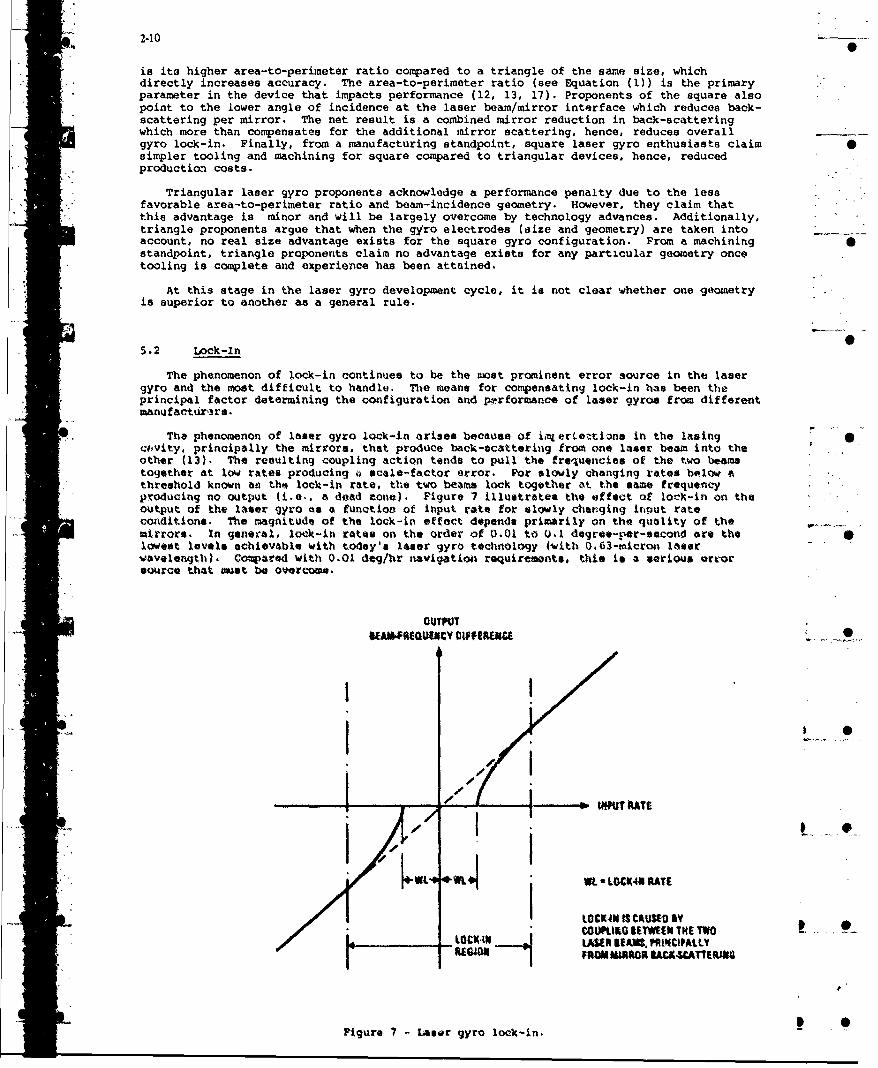
The phenomenon of laser gyro lock-in arises because of ii, erte-tiins in the lazingci#vity, principally the mirrors, that produce back-scattering from one laser beam into theother (13). The resulting coupling action tends to pull the frequencies of the two beamstogether at low rates producing " scale-factor error. For slowly changing rates below athreshold known as the lock-in rate, the two beams lock together at the same frequencyproducing no output (i.e., a dead zone). Figure 7 illustrate* the effect of lock-in on theoutput of the laser gyro ms a function of input rate for *lowly changing input rateconditions. The magnitude of the lock-in effect depends primarily on the quality of themirrors. In general, lo-k-in rates on the order of 0.01 to 0.1 degree-per-aecond are thelowest levels achievable with today's laser gyro technology (with 0,63-micron laserwavelength). Co;Varad with 0.01 dog/hr navigation requirements, this is a serious art-orsource that aot be overcome.
OUTPUT
I .
'7-I
_ I , - uraT
Wt- WL LOC:4N RATE
LOCK40IS CAUSED YCOMIKO IEM HETW
LO WIE LASER M)I PUS, ALLU
Figure ? - Laser gyro lock-in.

2-I I
Under dynamic input rates that rapidly pass through the lock-in region, the effect oflock-in is to introduce a small angle error in the gyro output as the lock-in zone istraversed, but still retaining sensitivity to input rate while in the lock-in region (i.e.,no hard dead-zone develops as in Figure 7 (12, 13, 16). The latter effect underlies thebasic principal behind adding cyclic high rate biap to the laser gyro as a means forcircumventing the lock-in dead-zone effect, and converting it into a random angle erroradded to the gyro output each time the biased gyro input cycles through the lock-in region. • •The principal method being used today to generate the oscillating bias in the laser gyro ismechanical dither.
5.2.1 Mechanical Dither
With mechanical dither, the oscillating bias into the laser gyro is achieved bymechanically vibrating the gyro block at high frequency about its input axis through a stiffdither flexure suspension built into the gyro assembly. The spoked-like structures inFigures 5 and 6 conceptually illustrate such a flexure that is attached to the laser block(on the outside) and to the gyro case/mount (on the inside) by metal rings that areconnected to each other by flexible metal reeds. Piezoelectric transducers attached to thereeds provide the dither drive mechanism to vibrate the gyro block at its resonant frequencyabout the input axis. One piezoelectric transducer is msechanized as a dither angle readoutdetector and used as the control signal to generate voltage into the drive piezo's tosustain a specified dither amplitude. The dither anqle amplitude and acceleration aredesigned so that the dwell time in the lock-in zone is short so that hard lock-in will neverdevelop. The result is a gyro that has continuous resolution o,er the colplete input raterange. The residual effect if lock-in is a small vandom angle error in the gyro output thatis introduced each time the gyro passes through 1( k-in (at twice the dither frequency).This is the principal source of random noise in "echaniqally dithered laser gyros. Therelationship between laser gyros random noise, lock-in, and dither rate is ideally given by
OL (2)
wh~ere
aR Gyro random noise (or "s.andom walk"') otmffieient (deg/hk) "...
L - Lock-Ln rate
0 " Dither rate a*pll1tude
K 9 Gyro output scl4 factor ill fringe* p"ar inpot rovolution (i.e., the rciprcalof the gyro "Puloo ai.**e diacueaed previously, tirmee 2) 2))
* or typical value* of lp - 0.002 deoghr½, qL 1 0.0 dog/see:. end K - 649,UO0 (i.e.. 2arc sec pulse size). equationi (2) can b* used to ehow that ui - 72 dog/saec. To achievesufficient lateral stifffess, the dither spring is deaigsw such that the frequency of thedither w)tion is oan the order of 400 hf. IhM associatwd dither cycle OatNitude (corre-s ponding to 72 dog/aac dither rate) is 103 arc swo (or 206 a4r eat peak-to-peak). tquation(2) is based co the assumption that the angle err'r gonerated in the gyro output is nicor-related from dither cycle to cycle. In practice ,I i.in not perfectly achievable. and*somwehat larqor dither auplitqdes are required than predicted by c•oation %2). Novertho-less. the figures presented previously are generally representative of typical mechanicaldithter requirements.
Once mechanical dither is intcorporated for lock-in comeneation. means ast be providedto reve- the oscillating bias signal from the gyro output (so the that the gyro outputrepresents the motion of the &snsor ass.~ly to which the gyro is amnte4). Figut- 5"illustrates the "case mounted readout" method of cptically cancelling the dither from theoutput. by •mttntig the readout reflecting prism and photodiodes oo the gyro Case (i.e.,off the gyro block) the translational novement of the gyro block relative to the case(caused by dither) will qenerate fringe motion at the photodiodes. This purely geometricaleffect can be made t') cAncel the fringe movement produced by the l ater block eensed ditherangular motion thrcugh proper selection cf the rotatio.'al center tor the *achaniaal dithermount. The result is a photodiode output Pignal that respond* to rotation of the gyro caseand not relative movement between the dithering gyro relative to the case. -0 -A
The alternative to *casa-mounted readout is "blck-mounted readout" as illustrated inFiguro 6. With this approach the gyro readout optics are mounted directly to the gyroblock. Relative mvovement between the blovk and case is removed by measurement andsubstraction, or by filtering. in the weasuruewnt/substraction approach, a transducer(typically electrosagnatiE) is used to electrically measure the instantanetos angle betweenthe gyro block and case. The electrical signal is then digitized and subtracte-d from thegyro pulse output for dither motion compensation. With the filter approach. a digitalfilter is used to filter signals near and above the dither frequency from the gyro output.

- 2-12
The result is a cancellation of the unwanted dither rate between the gyro block and case.*The penalty is attenuation of real oscillating rates of the gyro case which, if significant,
must be accurately measured for processing in the strapdown computer. Use of the filterapproach is only valid for relatively benign environment applications where it can beassured that the only angular rate signals that need to be measured have frequency contentwell below the dither frequency.
5.2.1.1 Mechanical Dither Design Complications - Orginally touted as a simple solution tothe lock-in problem with r~o deleterious side effects, the mechanical dither concept appliedin practice has been found to be the source of several subtle mechanical coupling error
A mechanisms that must be designed for at the three-gyro system level for solution (19, 34).It zruist be realized at the onset, however, that those complications are directly propor-tional to the magnitude of dither motion required for lock-in compensation. As lock-inrates are reduced, dither amplitudes can be reduced proportionally (see equation (2)), anddesign solutions for the effects described below can be more easily achieved.
The basic problem with mechanical dither stems from a kinematic property of three-axisrotary notion that cyclic rates in two orthogonal axes, if at the same frequency but phaseshifted by ninety degrees, will produce a real constant attitude rate about the third axis(33, 34). The effect, known as "coning", if present, must be measured as cyclic ratesignals by the strapdown gyros, and delivered to the strapdown computer so that the truedrift about the third axis will be properly calculated. The problem arises when gyro outputerrors are also being generated at the same frequency as the real rates to be measured.Cyclic error signals from the gyro in one axis, in combination with errors or real cyclicrates fromn the gyro in one of the other orthogonal axes, will produce a vector rate profile
A ~which appears as oconing, but is false ("pseudo-coning" is the nonxrenclature typically ucedto describe this phenonemon). Since the composite gyro output signals (real plus error) are
- processed in the same computer used to measure real conring motion. a pseudo-coning error* will be created in the strapdown computer as a false drift rate about the "third" axis.
Filtering the gyro signals to ruýmovo the output error oscillations is not acceptable if realcyclic motion is present, since the true drift caused by the real cyclic coning notion will.not be properly maesured and accounted for.
In the came of mechanically dithered laser gyrom. a potential souirce of real highfreqjuency coning in a itrapdown system is the reaction torque of the gyro dither 4rives intothe sensor assembly (the sensor assembly typically consists of a metal casting to which theagyros anid accelerometers -ire mounted). To minimizev dithar roaction torque resonan1ceeffects, and to provide coopliaknce for thermal qxpansion. twst RIA, sensor assemblies aremechanically isolated from the system chassis by slastomaric isolotor. (34). To generate
Sonin mtoqaanuar rote vibration frequencies must exist siinultanusyi worthogontil axon. Dither induced vibrations from nominally orthoqonail laser gyros into theeansor assembly can be*come freqotency co~rrelated between msif mechanical coupling 'tristsbetween the axes (e.g., princip,4l moment-of-inertia axos of the sensor 4astoly not presrlielto gyro input axes). The machAnical coupling mechanisms tend to pull the dither £requet~ciesio orthogonal axos together. thereby croAttag real coning at dither fr-wquency. Hence, evenoif single gyro dither frequeniels are separate, the =- chanical couplinig can shift thefreqluentcies tovcard each Other, thereby creating correiNted froqgnency cc~insbteaxon, or Lonting. Another source of real higjh froquency coning is linear randoft vibraitionspinto the sttraploamn systems that produce correlatod frequency rotary enotor amsotobly motion inorthogonal axes due to sensor assosbly/elastoesric mowtit avyurotries.
The real coning motion e(ffects described Above Would not be a problem in thomst~lvas.since l4asr tyros have the bandwidth and senn"itivity required for aoccurate * srmn of0these effects. Ilie problem arises troft pseudo-coning createdl at dither frequency, alsoL dueto dither meachanical interractioti. A classical example is soenor Asotably bending inducedby the dither reaction torque which produces false gyro ooutPuts at dithefr frequency (tt-g..due to beniding ini the mochanist. used to oeasure andl remove gyro block/case relattive :ingular
dither antiml fromt the gyro output, or gyro moount twisting about the gyro input axis).
Exacting and sohilsticated Mechtanical design techaniques mist be used in- the overarisensor, sensor assocrbly. andA sensor a.i -tmbly mount. to assure that pseudný-coning effect. Arenegligible below the frequencies vber^ real coning exists and has to be meas~ured (33. 34).The coning computation algorithma in too streptlown computer (33) cgn then be run ait aniteration rate that is only high enough to maeasujre the real coning mo.tion frequency. effects(i.e.. so that hiqh frequency pseudo-coning effect* *re attenuAted). Classical tecAniquosutilized to mintisize psuocnigefcts are to design for stiffness in the sendor assem-bly. design for wechanical symmsetry in th. sensor assembly to mkinimize. mechanical dithercross-coupling between gyro anes, and to as~iure sufficient gyro dither frequency separationso that the tendency for frequencey pulling toge~thtr is minivaized. if performed properly. atotal design can be acheived that sets overall cystem requirements under e~xternal vibra-tion. Proper design is iaar. easily achieved for benign vibration environments (e.g..coamerical aircraft).
5.2.2 Magnetic Mirror Bias
The magnetic-oitrror concept is a nonaechanical biasing tectiniquo based on the transverse

S1. -
2-13
magneto-optic Kerr effect (14, 18, 21). A special inner coating (e.g., ferromagnetic metal)is applied to one of the laser gyro mirrors which, when magnetized normal to the plane ofincidence by an applied magnetic field, imparts a nonreciprocal (i.e., opposite) phase shiftbetween the clockwise and counterclockwise laser beams. This produces an apparant differ-ential path-length shift between the laser beams which generates a frequency difference oroutput rate. The result is a bias imposed on the gyro output that is controllable by theapplied magnetic field. Bias uncertainties are compensated through use of alternating bias Icontrol (i.e., square-wave dithering of the applied magnetic field). The magnetic fieldintensity is set at a high enough level to operate the magnetic mirror in a saturated state.In this way, bias shifts generated by stray magnetic fields are minimized.
The advantage of the magnetic mirror is the elimination of the need for mechanicaldither, its associated design complications, and size/weight penalties. A problem area forthe magnetic mirror has been difficulties in generating a large enough bias for the 0.63micron laser gyro due to low reflectance of the ferromagnetic coating (14, 20). The S
* resulting loss must be compensated by higher gain in the laser helium-neon discharge. Forthe 0.63 micron laser, high gain cannot be tolerated because the laser begins to resonateunwanted mode shapes that deteriorate performance. The net result is that the magneticmirror biasing capability must be diluted by appropriate layering of dielectric coatings on
" the mirror to recover reflectance. The net bias levels achieved with this approach have notbeen sufficient to adequately compensate lock-in. (It should be noted that ferromagneticmagnetic mirror technology has been successfully applied to the lesser accurate 1.15 micronlaser gyro which can be operated at a higher gain before multimoding problems develop (24)).Another problem area for magnetic mirror technology has been the introduction of residual
* nonrecipocal phase shifts between the incident laser beams that are temperature sensitive.The result is a bias instability that is temperature sensitive and which produces turn-ontransients.
Recent work on laser gyro magnetic mirror technology has concentrated on the developmentof a garnet magnetic mirror in which the dielectric layer coatings on the laser mirror are"made with a transparent garnet film that produces nonreciprocal phase shift to incident 0light on application of a magnetic field (20). The result has been that the loss effect(associated with the ferromagnetic magnetic mirror technology) has been significantlyreduced so that high bias levels can be achieved with 0.63 micron lasers. Current design
* : work is concentrating on doping the garnet material to reduce the effect of residualnonreciprocal temperature sensitive phase shifts that have remained with the new garnet mir-ror technolgy. Engineering personnel associated with these developments are predicting abreakthrough within the next year based on experimental results achieved to date on dopedgarnet coatikzgs.
5.2.3 Multioscillator Laser Gyro
Conventional two-beam (clockwise and counterclockwise) laser gyros are designed toamplify plane polarized laser light (i.e., in which the electric vector normal to the laserbeam is either perpendicular to the lasing plane (S-polarization) or in the lasing plane(P-polarization). Triangular lasers typically use the former polarization while squarelaser gyros typically use the latter. In the case of the multioscillator laser gyro (26,
*"i * 27), circular polarization is used in which both S and P modes are simultaneously excited,but at one quarter wavelength phaue shifted from one another. The result is a combinedelectric vector polarization that spirals between S and P, denoted am circular polarization.Right circularly polarized (RCP) or left circularly polarized (LCP) light is generated bycreating a plus or minus quarter wavelength shift between the S and P waves, therebycret~ting a right or left sense spiralling electric vector wave. -
In the mult~oscillator, both RCP and LCP laser beams are created in the same cavity,' - each with clockwise and counterclockwise =cmponents (i.e., a four-beam Laser gyro). The two
polarization states are excited by a reciprocal polarization rotator (e.g., a quartz cry-stal) in the beam path that imparts an additional spiral rotation to the circularly polar-ized light, and which operates identically on both the clockwise and counterclockwisecomponents of the RCP or LCP beams (i.e., rocriprocal). The additional rotation adds to thespriilling for the RCP beam and retards the spiraling of the LCP beam. The effect of the
O*_• added rotation on the RCP beam is to resonate the light components with decreased wavelength .* such that a net spiral angle reduction is acheived around the beam path to match the spiral
angle increase across the rotator. As a result, the RCP beam (both the clockwise and- counterclockwise components) are up-shifted in frequency (proportional to the wavelength* i decrease). The opposite effect is created in the LCP light which is down-shifted in
frcquency by the same amount that the RCP light frequency is up-shifted. As for thetwo-beam laaer gyro, each polarization 8s ,.Le (RCP or LCP) contains a clockwise (Cw) and acounterclockwise (CCW) beam component. )fence, two sets of OW and CCW beams are established,
"- one RCP and the other LCP, each operating at a different center frequency. Each set is used ...to generate an independent output sigral equal to the frequency difference between the CWand CCW beamn. Ad for the two-beam laser gyro, the frequency difference output from each
- . polarization state is proportional to input rotation rate. Also, as for the two-beam lasergyro, the frequency difference output from the RCP and LCP lasers experience lock-in whichpull the CW and CCW fi ,quencies together at low input rates.
In order to overcome lock-in, a nonreciprocal polarization rotator is introduced intothe beam pith which rotates circularly polarized light in the opposite sense for clockwise

2-14
compared to counterclockwise beams. Hence, a frLquency shift is imparted between the,. clockwise and counterclockwise beams (i.e., a bias) for both the RCP and LCP light. The
frequency difference is maintained at a high enough level to remain far from the lock-inregion under frequency shifts produced by angular rate inputs. The common means for intro-ducing the nonreciprocal bias in the multioscillator laser gyro has been through use of aFaraday rotator consisting of a piece of amporphous glass placed in the beam path with amagnetic field applied across it parallel to the beam. The resulting Faraday effect intro-
"* duces the desired frequency bias on the circularly polarized ligat that is in the oppositesense for the LCP compared to the RCP light beams. As a result, the RCP beam output (i.e.,
"- .-.. the difference between the clockwise and counterclockwise RCP beam frequencies) is posi-"tively biased, while the LCP beam fr~aquency difference output is negatively biased by anequal amount.
By summing the outputs from the R"P and LCP beam sets, the input rate sensitivity is
doubled, while the Faraday bias effect is cancelled. The cancelling of the bias by summingboth outputs eliminates the need for alternating bias to compensate for Faraday rotator gain 0"uncertaincies. Elimination of the oscillating bias eliminates a main source of lader gyrorandom noise (i.e., dithering through the lock-in region). Hence, the random noise in the"multioscillator is lower, and closer to the theroretical limit created by random gain andloss of photons from the laser beams (25, 26).
* 5.2.3.1 Principal Error Sources - The basic principal behind lock-in compensation in themultioscillator laser gyro relies on the Faraday bias (and Faraday bias uncertainties) beingequal between the two laser beam sets so that they cancel one another. In practice, this isnot totally true, to a large degree because the operating frequencies of the left and rightcircularly polar.tzed lases sets are different by design. This frequency difference causeseach to behave slightly differently to the Faraday biAs, producing a net residual error whencombined. The error is both temperature and magnetically sensitive, requiring some degreeof magnetic shielding and temperature measutement compensation.
"AAnother source of bias error in the multioscillator is variations in the lock-incharacteristic bett ar the right and left circularly polarized beams. Even through theFaraday bias keept -to isers well outside of the lock-in region, small scale factornonlinearitics stiL .xict at the bias point caused by lock-in. Because the lock-in ratesfor the two beam sets differ, when the gyro outputs are summed, the residual lock-in erroreffects at the bias point do not cancel. The resulting bias error created is temperaturesensitive and can have unpredictable varations over time.
* Multioscillator design groups claim that the above effects are for the moot part,S . predictable and can be compensted sufficiently for satisfactory operation in high accuracy
applications.
Two areas where seriou3 errors cAn develop and are not easily compensated arise from* anisotropic and birefringence ef'4ecta introduced in the light beams as they pass through a
quartz crystal reciproccl polarization rotator and Faraday nonrociprocal rotator. The neteffect is to introduce unpredictable nonreciprocal path length variation between all fourbeaxs whch are tatqiorature, acceleration and magnetically sensitive.
Recent advances in multioscillator design techniques have replaced the quartz crystalreciprocal polarization rotator with an out-of-plane beam path geometry that rotates thelaser beata by optical reflection at the mirrors (thereby, mimicking the rotational effect of
* .the quartz crystal) (27). The result is elimination of birefringence affects originallycreated by the presence of the quartz crystal in the beam path. Current work on themultioscillator is addressing improved methods for providing nonreciprocal polarization -rotation that have small and more predictable error characteristics than were achieved withoriginal Faraday rotator design configurations.
5.3 Laser .gyro Performnce And Application Areas
* Over the past 6 years, the rinq laser gyro (RLO) has progressed from advanced devel- t .opment into full scale producti;.n in l-ntuh strapdown inertial navigation applications. Thesuccessful l-noph laser gyro system programs to date have utilized the 0.63 micron tran-sition with mechanical dither. "yetams in the l-nmph range have been developed by severalvxemting manufacturing groups for hoth coMarical and military application.
Porformance advancer, in =L. technology have been rapid. Continuing advances in lasergyro mirror technology has reduced lock-in (and randow noise) by more than ap order ofmagnitude over the past eight years. Lock-in rates lover than 0.0003 dog/hrl have been ...reported. Advanced development progra=m are now in progress to design laser gyros withperformance capabilities required for 0.1 nnph navigation applications.
PrIncipa2 problems remaining with RIO technology are size and weight for the highperformance applications, and size, weiqht,. and cost for the lower accuracy applications.For the higher performance applicatione, the total weight of an RLO otrapdown inertialnavigation system is typically 301 higher than its coaparable gimbaled system counterpart.Significant cost, reliability, and reaction time benefits for the RO Oystem, however, make

2-15
it an attractive alternative to the traditional gimbaled system. It is generally concededthat laser gyro performance in the lower accuracy AHRS and tactical missile midcourseguldance application areas is superior to the competing strapdown RIG or TRG strapdowntechnologies, however, size, weight, and cost advantages for the RIG or TRG with acceptableperformance are prevailing factors today that continue to restrict entry of the RLG into thelower performance application areas.
Performance advances in future RLG's may make it possible to build smaller, lighterweight laser gyro systems for the lower performance market. Advances in nonmechanicallydithered RLG technology may make it pxcssible in the future to build a a small sizecost/performance competetive integrated 3-axis laser gyro sensor assembly (1, 24) in asingle Zerodur structure using interleaved laser paths to reduce net size/weight. Ifadvances in mirror technology continue to reduce lock-in rates and associated ditheramplitude requirements, mechanically dithered RLG system size/weight will also be reduced inthe future. Production learning is expected to be the determining factor that will decide -the degree to which laser gyro production costs will be reduced in the future to be compet-itive with the lower performance RIG and TRG strapdown sensors. For the higher performancestrapdown applications areas, strapdown RIG and TRG manufacturer's generally conceed thatthe ring laser gyro is now the industry standard, and not a viable competition area forhigher performance but more expensive versions of strapdown TRG or RIG technology.
C. * ER-nTIC RXTAXIOK RATE 8SEOR
One of the newer rate sensor technologies that has emerged over the past few years isthe fibez-optic rotation rate sensor (28). The concept for the device is illustrated inFigure 8. Light generated from a suitable light source at a specified design frequency istransmitted through a fiber-optic coil. The light beam is first split by a beam-splitter sothat half the radiation traverses the coil in the clockwise (CW) direction, and half in thecounterclockwioe (CCW) direction. The emerging light from both ends of the coil are then9 Srecombined at the beam splitter, and transmitted onto a photodetector. The photodetector.outpnt power is proportional to the average irtensity of the recombined light.
i,,+ * 0<.
Ca.-...
Pigure 9 -Basio fiber-optic rotation rate sensor concept
Under rot.ation of thie device about an axis notwl to the plane of the fiber-optic coil,the effective optical path length ir changed for the CW couare4 to the MTW beams in amanner similar to the ring laser gVy•o. In the direction of rotation, the path lengthincroses (i.e.. a photon of liqht has to travorve the length of thi coil plus the dtatance 'that the coil has been rotated during the travarsal period). In the direction opposite tothe rozation, the light traverses the length of the coil, minus the distance that the coil
* has been rotated during the traversal period. Thi diferoa.cv botwoon the c.Xt and 04 opticalpath length*, then, is twice-the distance of rotation, ort
4 1. 2 L D LD "
L T l eere
L - Total fiber length

2-16
D Dia&ieter of coil (assumed circular)
-AL Difference between CW and CCW optical path-lengths
!-- = Input angular rate
C = Speed of light 0
This corresponds to a phase shift between the CW and CCW light beams emerging from the coilgiven by
2% AL 2% LD (3)
where
I = Wavelength of light source
Thus, the phase angle between the emerging light beams becomes proportional to the inputangular rate. This contrasts with the ring laser gyro resonato. for which the phase anglechange is p-oportional to the integral of the input rate (see Equation (1)). Hence, the 0fiber-optic rotation sensor is a "rate gyro" while the laser gyro is a "rate integratinggyro". The other difference between the two sensors io that the laser gyro CW and CCW beamfrequencies are shifted from each other proportional to the input rotation rate (due to theself-resonance of the laser): the frequencies for the CW and CCW beams in the fiber-opticrate sensor remain equal under rotation rates.
*. ,, The photodeiecto- in Figure 8 is used to sense the phase shift between the CW and CCWlear.., The amn ".tude of the combined beams at the photodiode equals the sum of theindividual bram amplitudes, including the phase shift factor. The result is a combined beamint,.n.itj wnich is maximum for AO - 0 and mininum (zero) for Aý ' (i.e., varies as COX(40/2)). The photodetecto" output is proportional to the light intensity, hence, alsovaries approximatel- La cos 2 (AO/2).
In order to achieve high set itivity (hirh bcale factor), i-e length L of the fiber coilis large. A typical value of L a 400 met-:s with D 0.1 meters and X - 0.82 micronsproduces ai A* froA equation (3) of approximately one radian at I rad/sec input rate.
6.1 Practical Desiqn Rafineme-ts
* As depicted in Figure 8, the fiber-optic rotation rate sensor haa fundamental errormechanisms that make it impractical to implement. .zaonq these are large tcale factor erroraassociated with photodetector scale factor uncertaint 4.es, light source intensity vetrietions, ,and light amplitude loa~ea in the fiber: Li, of r~tc sensitivity around zero input rate(due to the cosa (&4/2) output characteristic ,f the photodetector: phate angle varlAtionsdue to mechanical movement betwuen the beam splittor and fiber that produce changes i4 pathlength between tho M and CCV beass: and polarization state differences between the CW andCLW betam that produce phase Thifts due to tionreciproca). birrefringence and dnisotropicefeeots in the fiber material that are aggravated by environmeno.l exposure. Tc overcomethese fundamontil problems, rtcrnt fiber-optin rotation sa-sor configurations (28) have
* adopted refined interface and control eleme'ts such as those depicted in Figure 9.
In Figure 9, the discreto component bewo-.plitter in Figire 8 is replaced by fibcr-opticcouplers which cnosist of integrated fiber-optic junctions that split entering bears 50% tothe left and 501 to the right. A polariser MCJ is included to suppress unwantedpolarization staten in the light. Tha fiber itself is specifically manufactured t." preservea single polarization state (28' %-poltrization preserving fiber"). In this mannet,
. nonreciprocal fiber-boam interractio:in ato suppressed.
S.A light source (typi'cally a super-luminiscent diode uuch as Oa)ium Arsenide) transmits* nerrow frequenuy bandwidth light* into the fiber t.',t splits into CW and CCW comonents at* .the coupler junction. Acousto-optic shifters (A/O) (such as Bragg cells**) at the end of
"*Note - Original fiber-optic sensors used lewer light. One of the major technologicalbreak-throughs for the fiber-optic sensor was replacement of the coherent laserlight with a broader spectrum source. Tha result was a significant reduction iniaoilreuipkocai beam/fiber interraction error mechanisms due to the shortercorrelation distance for the 1.roader spectrum light (28, 29).
* "*Not* - A Bragg cell (28) is typically mechanized as a piezoelectric device that imparts anacoustical vibration transverse to the light beam at its input drive frequency.The result is a bending of the light (by the "Bragg angle") with an accompanyingfrequency shift in the light passing through the cell equal to the Bragg cell drivefrequency. 0 _

2-17 * _S
A/C"
POLARIZER FIBER-OPTIC 9f • "" %COIL .
LIGHT •"FOROI "•• •" i"
SOURCE COUPLERS ...
F2
PHOTOCETECTOR 3f E
SERVO
SHAPING UP-Davin OUTPUT i .
, • ~COUNTER FREQUENCY .'
VOLTAGE ICONTROLLED -OSCILLATOR
Figure 9 - Improved fiber-optic rotation rate sensor configuration.
the fiber coil are then used to generate a controlled phase shift in the light illuminatingthe photodector.
To function properly. each Bragg cell in Figure 9 must ý.e biased at a large offsetfrequency FP (typically 20 H•Iz). A Bragg cell mounted at one end of the coil in drivendirectly at the bias frequetvy Fj (see Figure 9) which up-shifts the light leaving the cellby FI from the light entering the cell, The light entering fromt the left (the clockwise CWbeam in Figure 9) must traverse the length of the coil at the up-shifted frequency before itleaves the coil and illuminates the photodetector. The beam entering from the right (thecounterclockwise CCW beam in Figure 9). on the other hand, immediately leaves the coil andilluminates the detector after it is frequency up-shifted. The net result is that the Cw 0 .beam travels a further distance at the up-shifted frequency than the CCW beam, therebygenerating a net phase shift between the CW and CCW boams at the photodetector proportionalto P, and the coil length.
The Bragg cell at the opposite end of the coil is driven at P2 which generates a phaseshift at the photodiode in the opposite sense to that created by the F1 Bragg cell. The P2frequency is controlled in servo fashion to maintain the photodetector output at peak power(i.e., zero net phaso angle). Under zero input angular rate, the F2 servo drive. F2 to .equal Fl (i.e., so that equal and opposite phase shifts are created that cancelone-another). Under input angular rate, the servo creates a frequency difference between F2and Fl, the device output in Figure 9, proportional to the input angular rate (thatgenerates an equivalent phase shift at the readout to null the phase shift created by inputrotation). It is easily demononstrated that the frequency difference generated to achieve anet zero phase angle is given byt
F 2 Fl 4A
•2 "F• "L-F (6

S.i .... ... .. .. .. ........where
*• = Length around one coil of the fiber (which typically consists of several coils).
If equation (5) is compared with equation (1) for the laser gyro resonator, it should beclear that they are identical on an integral basis (i.e., the frequency difference pulsecount cycles from equation (5) times 2% radians/cycle is proportional to the input angle bythe same factor that, in equation (1), relates RLG output fringe angle change to input anglechange.
Figure 9 also includes an electro-optic phase shifter (E/0) driven at frequency F3 atone end of the fiber, which imparts an oscillating path length change to the CW and CCWbeams passing through (Note: The E/O is typically mechanized as a piezoelectric actuated"stretcher" which physically changes the length of the fiber by introducing stresses in the -fiber proportional to applied voltage (28, 29). This induces an equivalent phase shift inthe light). Because the E/O driver is at one end of the coil, the light beam passing out ofthe coil delivers the phase shift effect first to the photodetector. The beam traveling inthe opposite direction has to traverse a longer length of fiber to the photodetector, hence,delivers its phase shift, by an equal amount, later. The delay creates an alternating phasebias at the photodiode mixed beam output, generating an oscillation of the output about thepeak power point. By comparing the positive half cycle output decrease with the negativecycle decrease, a linear signal can be generated proportional to the average deviation of . Sthe input light phase angle difference from zero. The linear signal is generated in thephase sensitive demodulator shown in Figure 9 driven by F-. The result is a signal out ofthe demodulator that is linearly proportional to the A4 phase deviation from zero, therebyeliminating the coo2 (At2) sensitivity problem around AO 0 that exists without the E/Odevice.
The basic advantages for the Figure 9 compared to the Figure 8 mechanization approach ...are the elimination of the discrete light/beam-splitter/fiber junctions, thereby reducing mphase shift errors caused by mechanical movement; elimination of the photodetectorzero-phase angle sensitivity problem through use of the E/O demodulator; and, through theclosed-loop servo operation that maintains the phase angle signal at null, elimination ofscale factor errors associated with light source intensity, optical intensity losses in thefiber and beam-splitters, and photodetector scale factor uncertainties.
6.2 Development Status And Application Areas
The basic iotivation behind the development of the fiber-optic rate sensor was to designa low cost alternative to the ring laser gyro that was inherently void of lock-in problems.The resonant characteristic of the laser gyro which regenerates its light source by stimu--lated emission, is the transfer mechanism that couples the CW and CCW beams together fromback-scatter, producing lock-in. For the fiber-optic rate sensor, the light source isexternal to the senuing ring, hence, does not amplify the effects of back-scatter. As aL -result, the lock-in phenomenon associated with the laser gyro is absent in the fiber-opticsensor. This has been proven experimentally (29). The rationale behind the projected lowcost of the fiber-optic sensor is that use of fiber-optics and integrated-optics tech-nologies should reduce labor hours associated with device manufacture. It also assumescontinuing reductions in the cost of high quality optical fiber which has been occuring overthe past few years. From a performance standpoint, the fiber-optic rotation sensor is notexpected to compete with the high performance laser gyro for accuracy, but is envisioned asa competitor to the lower coat autopilot, and eventually tactical missile and AMRS quality -gyros.
Much has been accomplished since 1976 when the fiber-optic rotation sensor concept wasoriginally conceived. To a large degree, these accomplishments are summarized by theevolution of the concept from its origiial form (in Figure 8) to its more refined practicalform (in Figure 9). Nevertheless, much remains to be accomplished before this device can beconsidered a various competitor with mature low cost conventional spinning wheel gyrotechnology or new lower cost/medium performance laser gyro technology. The device has still •__._ito be designed into a practical form that is producible at low cost, and which achievesoverall performance goals over opertional environments in a reasonable form factor. To alarge extent the development status reflects the level of funding committment assigned byindividual groups toward device development. Although many small funded activities haveexisted over the past 8 years, few dedicated programs have been heavily funded. Promanother standpoint, the funding limits could reflect lack of confidence by funding agenciesin the new technology, or a lack of available funds to pursue new technologies aftercompleting heavy investments in recent technologies that are only now entering large scale S -..
production (e.g., the laser gyro).
Some of the t.echnical problems that remain for the fiber-optic rotation rate sensor (28)include larger thun dosired size (2 to 4 inches in diameter) for the fiber-optic ring toavoid introducing beam interractions with the fiber walls under tight fiber turns: scalefactor errors due to photodiode output frequency variations with temperature; bias errorsassociated with photodiode output frequency side-bands creating phase offsets at thephotodetector: bias errors created from large required Bragg cell drive frequency offsets 9 ...coupled with variations in the CW and CCW Bragg biased coil lengths due to off-nominal

2-19
* variations between the Bragg cell distances to the fiber-optic coupler (see Figure 9); biaserrors associated with the E/0 demodulator electronics loop; bandwidth limits associatedwith the closed-loop operation in Figure 9; and increasing complexity of the sensor
*configuration to resolve problem areas. Virtually no data has been published on the* performance of the fiber-optic rate sensor under dynamic environments. one of the principal
potentional error mechanisms for the device (as for all angular rate sensing instruments) isbias error created under dynamic temperature, mechanical vibration, acoustic vibration,acceleration, and magnetic enviroments. Fiber-optic rate sensor enthusiasts remain con-fident that these problems can be resolved, given time and funding. For evidence they pointto the significant performance advances made over the past eight years, where thefiber-optic rate sensor has progressed from an original concept that could barely detect
*earth's rate, to current technology versions that have demonstrated milli-earth-ratesensitivities (29).
7.* PENDULOUS ACCELEROMETER
The pendulous accelerometer (Figure 10) (1) consists of a hinged pendulum assembly, amoving-coil signal-generator/pickoff that senses angular movement of the pendulum from a -
nominally null position, and a permanent-magnet torque-generator that enables the pendulumto be torqued by electrical input. The torquer magnet is fixed to the accelerometer case,and the coil assembly is mounted to the pendulum. Delicate flex leads provide electrical Saccess to the coil across the pendulum/case hinge junction. Electronics are included forpickoff readout and for generating current to the torquer.
PICKOFF ANdGLE
HINGE AXIS
(AXSE GENERATOR
REFERENCE PENDULUM AXISAXIS(CAE FIXED)
Figure 10 -Electrically servood pendulous accelerometer concept.0
The device in operated in the captured mode by applying electrical current to thetorquer at the proper magnitude and phasing to maintain the pickoff at null. Under thaseconditions, the electrically generated torque on the pendulum balances the dynamic torquegenerated by input acceleration normal to the pendulum plane. fience, the electrical currentthrough the torquer becomes proportional to input acceleration, and is the output signal forthe device.
* Mechanization approaches for the pendulous accelerometer (1) vary between manufacturers-it generally fall into two categoriest fluid filled and dry units. Fluid-filled devices
Aite a viscous fluid in the cavity betweer, the pendulum and case for damping and par~tial-.,atation. The dry units use dry air, nitrogen, or electromagnetic damping.
The binge element for the pendul1ous accelerometer is a flexible member that is stiff*normal to the hinge line to maintain mechanical stability of tlte hinge axis relative to the* case under dynamic loading, but flexible about the hinge line to minimize unpredictable* spring restraint torques that cannot be distinguished from acceleration inputs. Materials
selected for the hinge are chosen for low mechanical hysteresis to minimize unpredictablespring-torque errors. To minimize hystersis effects, the hinge dimennions are selected toassure that hinge stresses under dynamic inputs and pendulum movement are well below the
4 yield-stress for the hinge material. Beryllium-copper has been a commvonly used pendulum-hinge material due to its high ratio of yield-stress to Young's modulus (i.e., the ability 0to provide large flexures without exceeding material yiold-stress). Another successful

2-20
design approach for dry accelerometers has utilized fused quartz for both the hin e andpendulum by etching the complete assembly from a single-piece quartz substrate (17.
7.1 Performance And Application Areas
The pendulous accelerometer continues to be the primary mechanization approach beingused for almost all strapdown applications. Design refinements over the past 6 years now
* provide units from several manufacturers that meet 1.0 nmph strapdown inertial navigationrequirements in heaterless configurations. The heaterless configuration operates withouttemperature controls and achieves its accuracy through thermal modeling of the sensor errorsin the strapdown system computer based on temperature measurements taken with temperatureprobes mounted within the sensing unit. The heaterless accelerometer configuration has beenperfected within recent years for operation with ring laser gyros which are also operatedheaterless using direct path-length control to stabilize performance (Note: Use of heatersto control temperature and stabilize performance with the ring laser gyro is impractical dueto the long thermal time constant of the Zerodur material from which it is constructed, andthe associated reaction time penalty that would be introduced from turn-on until tempera-ture/performance stabilization. Laser gyro performance variations with temperature are also
* compensated by thermal modeling). It is highly fortunate that pendulous accelerometerdesigns originally developed for heated operation (to stabilize performance), have beenpredictable enough thermally, to allow accurate characterization over their completetemperature range by analytical modeling using temperature measurements. Hence, major design
.* refinements for heaterless operation have not been necessary.
Most accelerometers today are of the dry pendulous metal flexure hinge variety (1).Design refinements in quartz hinge design configurations (1) (most notably in the platingtechnology used to conduct current across the hinge into the pendulum-mounted torquer coilto minimize hysteresis) have provided a rugged unit that meets 1.0 nmph strapdown inertialnavigation accuracy requirements. -
Experimental pendulous accelerometers have recently provided indications that"identifiable futher design refinements will make it possible to achieve the accuracyimprovements needed for the advanced 0.1 nmph INS applications, Advanced engineering
"* daveloment programs are currently being funded (at a fairly modest level) to develop andevaluate these performance improvements.
Unit costs for the pendulous accelerometer, although acceptable, still remain higher L .than desirable, particularly in the higher accuracy applications. Competitive sourcing insome applications has created the environment needed to reduce costs to some extent throughdesign, manufacturing, and test improvements. Increased production volume has added to costreduction through learning and improved tooling/automation techniques. However, theproduction volume has not been sufficient to develop the automatic manufacturing technol-
* ogies needed to make major in-road. in cost reduction. Nevertheless, the pendulousaccelerometer cost is acceptable for moat applications, compared to the cost of otherstrapdown system elements. L-
8. TOROUE-LOOP MECHANIZATION APPROACHES FOR TORQUE REBALANCE INSTRUMENTS
The implementation of the torque loop for the torque-to-balance instruments (e.g.,floated rate-integrating gyro, tuned-rotor gyro, pendulous accelerometer) continue to bemechanized using different approaches, depending on manufactert digital pulse-rebalance or"analog-rebalance with follow-up pulse-rebalance logic, using pulse-on-demand or pulse-width-modulated forced limit-cycle techniques (1). Little data has been published on theperformance of these electrical circuits, an unfortunate circumstance, particulary sincetheir accuracy is a key contributor to the overall performance of the intrument they aredesigned to operate with. Performance data advertized as representative of particularsensors does not always include the effect of the digital pulse-rebalance circuity (i.e.,the data was taken on an analog basis at the basic instrument level). This becomes ofgreater concern when one considers the more demanding application areas that can requiredynamic ranges (maximum input versus bias accuracy) in the 106 to 107 category.
9. THE VIBRATING BEAM ACCELEROMETER
Much of the cost for conventional pendulous electrically-servoed accelerometers isassoviated with the torque-generator and electronics net.ded to close-the-loop on theinstrument and generate precision pulse outputs representing quantized increments ofintegrated input acceleration (1). The vibrating beam accelerometer replaces thetorque-rebalance mechanism with an open-loop direct-digital-output transducer based onquartz-crystal oscillator technology (30, 31, 32). The concept is depicted in Figure 11.
In Figure 11, two guartt-crystal beams are mounted symmetrically back-to-back so thateach axially supports a proof mass pendulum. Each beam is vibrated at its resonantfrequency by an electronics loop in a manner similar to the method used to sustain amplitude ,in quarts-crytal oscillator clock references. In the absence of acceleration along the

2-21
FLEXURE PENDULOUS
QUARTZ CRYSTAL"ACCELERATION BEAMSENSING
.'. i O~CRSTALLAO lOSCIRCUITOR f,
Figure 11 - Vibrating beam accelerometer concept.
* acceleration sensing axis, both beams are selected to nominally resonate at the samefrequency. Under applied acceleration, one beam is placed in compression and the other intension by the inertial reaction of the pendulous proof masses. This produces an increasein frequency for the beam in tension, and a decrease in frequency for the beam in com- ,..pression. The frequency difference (P2 - P, in Figure (11)) is a direct digital output
* 1proportional to the input acceleration.
* The symmnetrical arrangement of the beams produces a cancellation of several erroreffecte that would exist for one beam mounted individually. Lrror effects that arenominally cancelled include nominal beam frequency variations with temperature and aging,as ywnetrical scale factor noalinearities, anisolnertia errors (1). and vibropondulous errors
-D. (1) that are common between the individual beam assemblies.
- 9.1 Design Considerations And Application Areas
The vibrating beam accelerometer is being designed as a lo.ter cost alternative to theconventional pomudulous electrically-servoed accelerometer for strapdown applications. Oostreductions are expected to be achieved through elimination of the complex electro-mochanicalassembly associated with the pendulous accelerameter torque-generator, and elimination ofcompqlex torque-to-balance and pulse quantizer readout electronics.
* . The ultimate success of the vibrating beam accelerometer will depend on whether itmaccuracy capabilities will approach those of mature technology pendulous accelerometers at acompetetive price. Error ,nechanisms in the vibrating beam accelerometer arise from unpre-dictable variations between the two beam assemblies that are temperature, vibration sen-sitive and which vary over time. One of the more important error mechanisms that must bedealt with in the design of the unit is the potentional problem of mechanical couplingbetween the beam assemblies that pull the frequencies together under low input acceleration(an effect similar to lock-in for laser gyros). Tht result is a detection threshold for theunit that is a function of the strength of the ,nechanical coupling. The key to the design"of an accurate vibrating beam accelerometrr lies in the ability to isolate one cryteal beam"from the other. One approach being used to achinve isolation is through application of adual-beam construction (32) for each of the crystal beam assemblies as illustrated inFigure 12.

2-22 , -.
E LCOS C ILLA TO R . " "' "" ' " "
LSINRI
I'. I
Figure 12 - Dual-beam crystal oscillator concep.,..
In Figure 12, each beam assembly is composed of an integrol dual-beam arrangement inwhich the beam elements vibrate in opposition (180 degrees out of phase). The resulting .....counter-vibration allows each beam movement to be counter-acted mechanically by the othersuch that no net vibration is transmitted into the mount (i~e., similar to a tuning fork).The result is that mechanical coupling mechanisms between the independent dual-beamassemblies are minimized.
A problem area being addressed in the design of the vibrating beam accelerometer is theoutput resolution. Typical mechanizations are based on using crystals with a 40 KIRZ centerfrequency (zero input acceleration) with 101 variation over the design acceleration range.Hence, the inherent maximum frequency output of the device (beam frequency difference) undermaximum input acceleration is typically 5 to 10 K•z. For the higher accuracy applications,this resolution is generally too coarse (by at least an order of magnitude under certainconditions). In order to enhance the basic resolution, *esign techniques being investigatedinclude using time measurement between frequency difference pulses as the output, or use ofdigital phase-lock loop external circuity to generate higher frequency waveforms whoseintegral tracks the frequency difference output signal. 9 -
The vibrating beam accelerometer is still in its development stage with units becomingavailable for evaluation by test groups this year. Developmental test results reported todate have been encouraging. It is too early at this time to predict what the ultimate cost/performance of the device will be compared to mature pendulous accelerometer technology.
10. COCLUDING RJ4ARS 0 0"
Over the past six years, the laser gyro has emerged as the rate sensor most suitable forthe high performance strapdown applications. Floated rate-integrating and tuned-rotor gyrotechnologies continue to be the most suitable rate sensors for the low-to-medium perform-arna/low-cost application areas where small size is also important. It is expected thatcost and size reductions for the laser gyro will broaden itu applicability range in thefuture so that it will eventually dominate the medium accuracy performance areas as well.It is too early to predict whether the laser gyro will ever be of a low enough cost tosuccessfully coqte in the lower accuracy tactical missile application areas.
Pendulous accelerometer technology continues to be the main stay for strapdownapplications. Performance advances and some cost reductions over the past few years haveenabled this instrument to remain compatible with overall strapdown system cost/performancegoals. To generate a significant coat reduction for strapdown accelerometers, the vibratingbeam accelerometer is receiving attention by some development groups. Time will tellwhether the cost/performance of this instrounent will successfully compete with pendulous - .accelerometers in the future.
2-23
11. ACKNOWLEDGEMENTS
I would like to express my appreciation to engineering personnel in the followingorganizations who participated in valuable technical discussions on strapdown sensortechnology during the preparation of this paper. These discussions provided the primarysource of technical information for the paper.
Honeywell Avionics Division, Minneapolis, MNLitton Guidance & Control Systems, Woodland Hills, CANaval Research Laboratory, Washington, DCRaytheon Equipment Development Laboratories, Sudbury, MARockwell Autonetics, Anaheim, CASinger Kearfott, Wayne, NJSperry Gyroscope, Great Neck, NYSundstrand Data Control, Redmond, WA 0Sundstrand Optical Technologies, Newbury Park, CA
REFERENCES
1. Savage, Paul G., "Strapdown Sensors", "AGARD Lecture Series No. 95t Strapdown Inertial 9 0Systems - Theory And Applications", June--978.
2. Savage* Paul G., "Laser Gyros In Strapdown Inertial Navigation Systems", IEEE PLANS,Hilton Inn, San Diego, CA, November 1 - 3, 1976
3. Dynamic Errors in Strapdown Inertial Navigation Systems, NASA Report CR-1962,December 1971.
4. Wrigley, W., Hollister, W.M., and Denhard, W.G.,"Gyroscopic Theory, Design, andInstrumentation", M.I.T. Press, 1969.
5. Macomber, George R., and Fernandes, Manuel, Inertial Guidance Engineering, Prentico-Hall,Englewood Cliffs, New Jersey. 1962.
6. Howe, Edwin W., "A Free Rotor Gyro", Symosium on Unconventional Inertial Sensors,Parmingdale, New York, 1963.
7. Savet, Paul H., *New Trends in Non-floated Precision Gyroscopes", Grwman ResearchDepartment Memorandum RN-247J, October 1964.
8. Craig, Robert J.G., "Theory of Operation of Elastically Supported Tuned Gyroscope",IEEE Transactions on Aerospace and Electronic Systems, Vol. AES-8, No. 3, may 1972.
9. Craig, Robert J.G., "Theory of Errors of a Multigimbal, Elastically Supported, Tuned _.Gyroscope'" IEEE Transactions on Aerospace and Electronic Systems, Vol. AES-8, No. 3,May 1972.
S10. Craig, Robert J.G., Dynamically Tuned Gyros in Strapdown Systems", AGARD ConferenceProceedings No. 116 on Inertial Na•igation Components and Systems, AD-756 127, Paris,France, February 1973.
11. Killpatrick, Joseph, "The Laser Gyro", IRU Spectrum, October 1967. .
12. Aronowitz, Frederick, "The Laser Gyro", Laser Applications Vol. 1, Academic Press,New York, 1971.
13. Aronowite, Frederick, and Collins R.J., "Mode CouplLng Due to back Scattering in a lHeNoTraveling wave Ring Laser", Applied Physics Letters, Vol. 9, No. 1, 1 July 1966.
14. Dewar, Dr. D., "The Laser Gyroscope", Royal Aeronautical Society, London, 12 January 1977. -9
15. Harmons, Seridan W., and Ashby, Val J., "Mechanically Dithered RLO At The Quantum Limit',0547-3578/82/0000-0388 Copyright 1982 IEEE.
16. Hutchings, T.J., and Stjern, D.C., "Scale Factor Non-Lineatity of a Body Dithered Lasergyro", IEEE NAECON, 1978, Vol. 2, Pg. S49.
17. Hutchings, T., "Development And Test of A Small Body Dithered Laser Gyro",
Electro-Optics/Laser 77 Conference & Exposition, Anaheim, CA, Oct. 25-27, 1977.
1E. lione", R.D., Whitcomb, E.C., and Vescial, i.., "Ferrimagnetic Garnets As Laser Gyro"% Faraday Elements", Electro-Optica/Laser 77 Conference & Exposition, Anaheim, CA,
Oct. 25-27, 1977.
19. Mark, John C., Ebner, Robert E., and Brown, Alison K., "Design of RLG Inertial SystemsFor High Vibration, IEEE PLANS, Atlantic City, NJ, December 6-9. 1982. ____

2-24
20. McClure, R.E., and Vaher E., "An Improved Ring Laser Bias Element", CH1336-7/78/0000-0544Copyright 1978 IEEE.
21. McClure, R.E., "An Electrical Equivalent Circuit For The Tranverse Mangeto-Optic EffectIn Thin Magnetic Films", International Magnetics Conference, Boston, MA, April 24, 1980.
22. Freiser, M.J., "A Survey of Magneto-Optics Effects", IEEE Transactions on MagneticsMAG-4, 152, 1968.
23. Dillon, Jr., J.F., "Magneto-Optical Properties of Magnetic Garnets", Physics of MagneticGarnets, pp 379-415, A. Paoletti, ed; North Holland, 1978.
24. Morrison, R.F., Levinson, Dr. E., and Bryant Jr., B.L., "The SLIC-7 Laser Gyro, InertialGuidance System", NAECON, Dayton, Ohio, 1977.
25. Dorshner, Terry A., Hermann, A. Haus, Holz, Michael, Smith, Irl W., and Statz, Hermann,"Laser Gyro At Quantum Limit", IEEE Journal of Quantum Electronics, Vol QE-16, No. 12,December 1980.
26. Mathews, James B., Gneses, Morris I., and Berg, Dennis S., "A High Resolution Laser Gyro",NAECON May 16-18, 1978, Dayton, Ohio.
27. Statz, H., Dorachner, Terry A., Holz, M., and Smith, Irl W., The Multioscillator Ring SLaser Gyroscope, Raytheon Research Division Technical Report T-1096, January, 1983.
28. Ezekiel, S., and Arditty, H.J., ed. Fiber-Optic Rotation Sensors, Proceedings of theFirst International Conference, M.I.T., Cambridge, MA, November 9-11, 1982; Published inSpringer Series in Optical Sciences, Vol. 32, Schawlow, Arthur L., ed., Springer-VerlagBerlin Heidelberg New York 1982.
29. Burns, W.K., Moeller, R.P., Villarruel, C.A., and Abebe, M., "Fiber-Optic Gyroscope with _Polarization-Holding Fiber". Optics Letters, Vol. 8, No. 10, October 1983.
30. Albert, William C., and Weber Raymond E., "Vibrating Beam Accelerometer For StrapdownApplications", IEEE PLANS, Atlantic City, NJ, December 6-9, 1982.
31. Albert, William C., "Vibrating Quartz Crystal Beam Accelerometer", Copyright ISA. 1982,ISBNt 0-87664-689-5.
32. Cogic, A.M., and Peters, R.B., "Description And Test Methods For A Frsquency OutputAccelerometer", Inertial Navigation Test Sympoeium. Holloman APB, 1983.
33. Savage, P.G., "Strapdown System Algorithms". ASARD Lecture Series No. 133: AdvancesIn Strapdown Inertial Systems". May 1984.
34. Savage, P.G., Introduction To Strapdown Inertiel S StasM, June 1, 1903 (Third Printing),and Introduction To1 tpdon Inertial NaVigat.n at*e - Supplemental Material,Novem•er 14. 19833 Third Strapdown Aseoci6ate Open Seminar On Strapdownniirtai-Navigation Syetems, Marquette Inn, Miruneaolis, MR, Nov. 14-18, 1983.
So -
!..
* 0
,!*
![[XLS]lbacon/acct400/templates/Chap003.xls · Web viewGiven P03-34 P03-34 Given P03-32 P03-32 Given P03-30 P03-30 Given P03-27 P03-27 Given P03-26 P03-26 Given P03-25 P03-25 Given](https://static.fdocuments.in/doc/165x107/5ae12dc87f8b9a6e5c8e6532/xls-lbaconacct400templateschap003xlsweb-viewgiven-p03-34-p03-34-given-p03-32.jpg)