ADJUSTABLE AIR HYDRAULIC SLIDING JACKBEAM 7000 lbs… · AIR‐HYDRAULIC SLIDING JACKBEAM 7000 lbs....
13
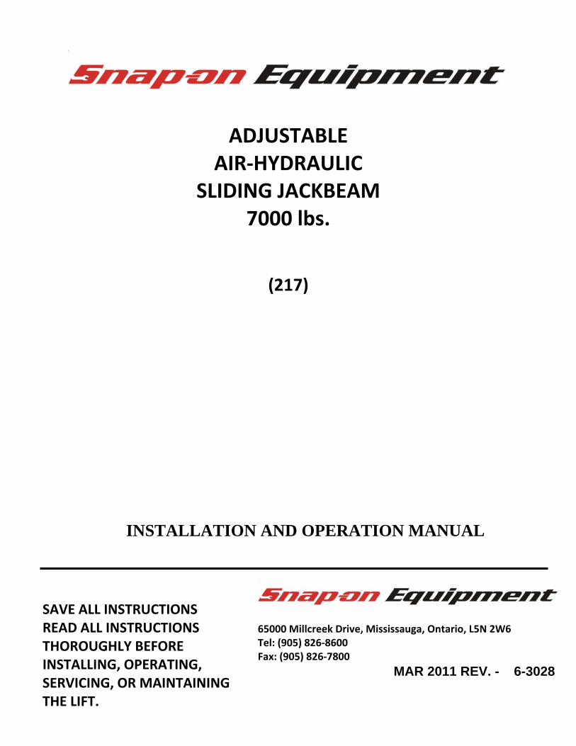
ADJUSTABLE AIR‐HYDRAULIC SLIDING JACKBEAM 7000 lbs. (217) 65000 Millcreek Drive, Mississauga, Ontario, L5N 2W6 Tel: (905) 826‐8600 Fax: (905) 826‐7800 MAR 2011 REV. - 6-3028 SAVE ALL INSTRUCTIONS READ ALL INSTRUCTIONS THOROUGHLY BEFORE INSTALLING, OPERATING, SERVICING, OR MAINTAINING THE LIFT. INSTALLATION AND OPERATION MANUAL
Transcript of ADJUSTABLE AIR HYDRAULIC SLIDING JACKBEAM 7000 lbs… · AIR‐HYDRAULIC SLIDING JACKBEAM 7000 lbs....
ADJUSTABLE
AIR‐HYDRAULIC SLIDING JACKBEAM
7000 lbs.
(217)
65000 Millcreek Drive, Mississauga, Ontario, L5N 2W6 Tel: (905) 826‐8600 Fax: (905) 826‐7800
MAR 2011 REV. - 6-3028
SAVE ALL INSTRUCTIONS READ ALL INSTRUCTIONS THOROUGHLY BEFORE INSTALLING, OPERATING, SERVICING, OR MAINTAINING THE LIFT.
INSTALLATION AND OPERATION MANUAL

2 of 13
JACKING BEAM INSTALLATION AND OPERATION MANUAL The jacking beam should only be used with lifts installed on level concrete floors conforming to the installation instructions for the lift. Consult lift installation instructions for concrete thickness and strength requirements. Ensure clearance around and above lift conforms to installation instructions for the lift.
ATTENTION! This lift is intended for indoor installation only. It is prohibited to install this product outdoors. Operating environment temperature range should be 41 – 104 °F (5 – 40 °C). Failure to adhere will result in decertification, loss of warranty, and possible damage to the equipment.
Installation of lifts shall be performed in accordance with ANSO/ALI ALIS, Safety Requirements for Installation and Service of Automotive Lifts For additional safety instructions regarding lifting, lift types, warning labels, preparing to lift, vehicle spotting, vehicle lifting, maintaining load stability, emergency procedures, vehicle lowering, lift limitations, lift maintenance, good shop practices, installation, operator training and owner/employer responsibilities, please refer to “Lifting It Right” (ALI/SM) and “Safety Tips” (ALI/ST). For additional instruction on general requirements for lift operation, please refer to “Automotive Lift‐Safety Requirements For Operation, Inspection and Maintenance” (ANSI/ALI ALOIM).
3 of 13
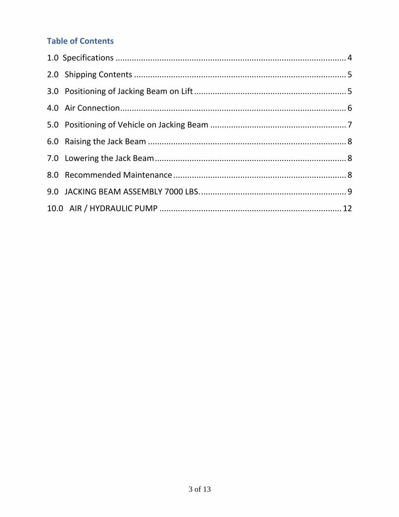
Table of Contents
1.0 Specifications .................................................................................................... 4
2.0 Shipping Contents ............................................................................................ 5
3.0 Positioning of Jacking Beam on Lift .................................................................. 5
4.0 Air Connection .................................................................................................. 6
5.0 Positioning of Vehicle on Jacking Beam ........................................................... 7
6.0 Raising the Jack Beam ...................................................................................... 8
7.0 Lowering the Jack Beam ................................................................................... 8
8.0 Recommended Maintenance ........................................................................... 8
9.0 JACKING BEAM ASSEMBLY 7000 LBS. ............................................................... 9
10.0 AIR / HYDRAULIC PUMP ............................................................................... 12
4 of 13
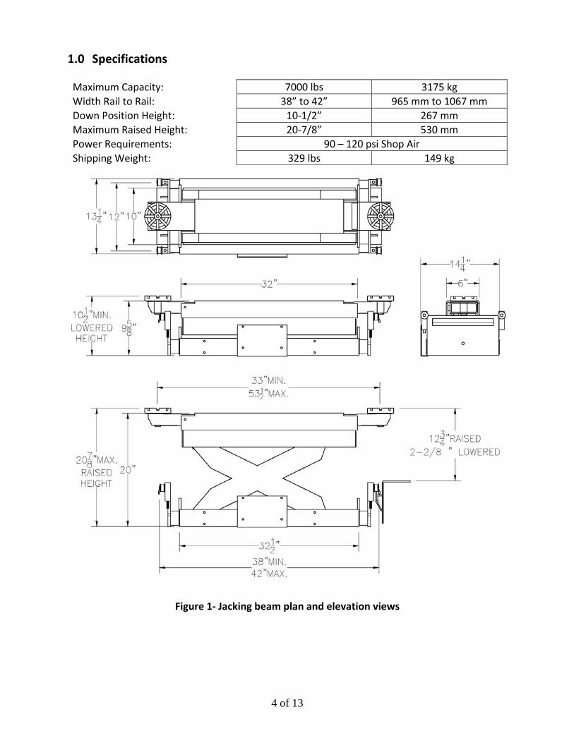
1.0 Specifications Maximum Capacity: 7000 lbs 3175 kg Width Rail to Rail: 38” to 42” 965 mm to 1067 mm Down Position Height: 10‐1/2” 267 mm Maximum Raised Height: 20‐7/8” 530 mm Power Requirements: 90 – 120 psi Shop Air Shipping Weight: 329 lbs 149 kg
Figure 1‐ Jacking beam plan and elevation views
5 of 13
2.0 Shipping Contents The jacking beam is fully assembled and packaged to protect it from any damage that may occur during shipping. Included are the following components:
Jacking beam assembly, including: ‐ Jacking Beam Body ‐ Lifting Arms ‐ Roller Adapters ‐ Air/Hydraulic Pump
Jacking Beam Keeper Kit Stack Pads & Adapters Installation & Operation Manual
3.0 Positioning of Jacking Beam on Lift 1. The Jackbeam must be positioned on the lift correctly prior to usage. The pump side of the
Jackbeam should face outwards.
2. Extend each Roller Adapter from the base of the Jackbeam and place on lift with rollers centered on the Jackbeam rails.
3. To ensure that the Jackbeam is centered between the decks, the adapters must be equally
spaced on both sides of the base. Tighten top screws, NOTE: DO NOT EXTEND ADAPTERS MORE THAN 3” FROM BASE. SAFETY STOP SCREWS ARE PROVIDED.
4. Slide the Jackbeam on onto rail from front and/or rear of lift.
5. Adjust the keeper bolts located at sides of Jackbeam to ensure they are unscrewed to a
distance, just below the Jackbeam rail. These are to keep the Jackbeam secured to the rail.

6 of 13
4.0 Air Connection 6. The jacking beam must be connected to the air supply in order to operate. There are (2) two
configurations for the air supply to be connected.
a. The Jackbeam is shipped pre‐assembled to install at the front of the lift. The air connection bracket is on the rear left side of the Jackbeam.
b. To install the Jackbeam at the rear of the lift, the air connection bracket must be removed and reinstalled on the rear right side. Disconnect the 3/8” polytube, reroute, cut to length and reinstall.
7. Attach the recoil hose to the bulkhead fitting on the Jackbeam and the other end to the
bulkhead fitting on the side of the lift runway.
NOTE: The Jackbeam is to be used on a lift with air connections located at the center of the runway. If your lift is equipped with air connections at the ends of the runway, Relocation Kit #01691 can be used.
8. Prior to placing vehicle on lift, raise and lower the Jackbeams multiple times and check for air and hydraulic leaks. See sections 6.0 Raising the Jack Beam and 7.0 Lowering the Jack Beam for operation instructions.
NOTE: Keep the air source clean and make certain that an air filter/oiler is used to keep dirt out of the air motor. Failure to provide clean air may void manufacturer’s warranty.

7 of 13
5.0 Positioning of Vehicle on Jacking Beam 1. The vehicle must be positioned correctly on the lift prior to raising the vehicle with the
jacking beam.
LIFTING AN IMPROPERLY POSITIONED VEHICLE WITH THE JACKBEAM INCREASES THE POSSIBILITY OF ONE DECK LEADING OR LAGGING THE OTHER DECK. NOTE: USE ONLY THE SAME LIFTING PADS ON BOTH ARMS.
2. Move the jacking beam to the desired pickup area and connect the air line (if not permanently connected).
NOTE: EASE OF POSITIONING WHILE JACKING BEAM IS NOT UNDER LOAD IS DUE TO THE TRACK ROLLER ASSEMBLIES. THE ROLLER ASSEMBLIES ARE SPRING LOOADED TO CARRY THE WEIGHT OF THE JACK ONLY. WHEN THE JACKING BEAM IS UNDER LOAD THE JACK RESTS ON ITS STRUCTURE AND CANNOT BE MOVED.
3. With the jacking beam positioned at the desired working location, select the proper lifting pads. Insert the lifting pads into the arms.
NOTE: LIFT VEHICLE AT MANUFACTURER’S RECOMMENDED PICKUP POINTS ONLY. PLEASE REFER TO “LIFTING IT RIGHT” (ALI/SM).
4. With the vehicle’s center of gravity equally spaced between the decks, the jacking beam can be used to lift the vehicle. Select lifting points that are the same distance from the centerline of the vehicle, i.e. position the jack beam pads so that they make contact at the same point on each side of the vehicle.
8 of 13
6.0 Raising the Jack Beam 1. Press the up button and hold until jacking beam is at full working height and the automatic
safety is in place. Lower the jack beam onto the safety (Note: there are two safety stops to allow multiple working heights).
NOTE: NEVER WORK ON A VEHICLE UNLESS THE SAFETY LOCK IS ENGAGED AND THE JACKING BEAM CANNOT BE LOWERED.
7.0 Lowering the Jack Beam 1. To lower the jacking beam, first raise the jack up off the mechanical safety lock and release
the safety lock using the safety release lever.
NOTE: THE SAFETY LEVER MUST BE MANUALLY HELD IN THE RELEASED POSITION.
2. Press the control handle to release pressure allowing the jacking beam to lower to its full down position.
3. Never operate a jacking beam that is not in proper working order or in a manner not
recommended by the vehicle or jacking beam manufacturer. ALWAYS ENSURE THAT THE MECHANICAL SAFETY IS ENGAGED WHENEVER A VEHICLE IS SUPPORTED BY THE JACKING BEAM.
8.0 Recommended Maintenance 1. Inspect the jacking beam on a daily basis to ensure the jacking beam is in proper working
condition. 2. Make certain that the automatic safety drops into place when the jacking beam is raised
and that it will release when held in the down position during lowering. 3. Check the hydraulic fluid when jacking beam is in the lowered position by removing the
filler breather cap. 4. Keep the air source clean and make certain that an air filter is used to keep dirt out of the
air motor. 5. Keep the entire jacking beam as clean as possible at all times. 6. To maintain a clean shop air supply, (oil, lube, filter and regulator) should always be in good
working order in conjunction with the use of an oiler/separator.

9 of 13
9.0 JACKING BEAM ASSEMBLY 7000 LBS.

10 of 13
ITEM QTY. DESCRIPTION PART # 1 1 BASE FRAME WELDMENT 3‐0842 2 1 OUTER SCISSOR WELDMENT 3‐0824 3 1 INNER SCISSOR WELDMENT 3‐0825 4 1 WASHER, 1 1/32” ID 6‐0807 5 1 SCISSOR CENTER SHAFT 1‐2270 6 1 CENTER PIPE SPACER 1‐0575 7 4 SPRING PI, 3/16” X 2” LG 6‐0146 8 4 BUSHING 6‐2320 9 2 WASHER 6‐0807 10 4 PLASTIC GLIDE BLOCK 1‐3674 11 4 WASHER, 5/8” 6‐1401 12 4 NYLON LOCKNUT, ½‐13UNC 6‐1553 13 1 UPPER SCISSOR PIN 1‐1999 14 2 LOCKWASHER, ¼” ID 6‐0056 15 1 SET SCREW 1/4 ‐20 X 1 1/2 6‐0438 16 1 TOP WELDMENT 3‐0171 17 18 19 2 LIFTING ARM WELDMENT 2‐1572 20 2 HEX HD BOLT, 3/8”‐NC X ¾” LG 6‐0030
22 2 STACK PAD ASSEMBLY COMPLETE 1‐3278 23 2 STACK PAD WELDMENT 2‐2514 24 2 RUBBER PAD 3‐0872 25 2 ALLEN HD FLAT SCREW ¼” – 20 X ¾”LG. 6‐1086 26 2 STACK PAD ADAPTER, 3” 1‐3280 27 2 STACK PAD ADAPTER, 6” 2‐1580 28 1 CYLINDER ASSEMBLY COMPLETE 3‐0474 * 1 CYLINDER ASSEMBLY (ALTERNATE) 3‐1069 29 1 VELOCITY FUSE 1‐1726 * 1 FLOW CONTROL (ALTERNATE) 6‐3861 * 1 ADAPTER, 3/8” JIC F – ¼” JIC M (ALTERNATE) 6‐0974 38 1 OUTSIDE CYLINDER SHAFT 1‐1158 39 1 INSIDE CYLINDER SHAFT 1‐1163 40 1 SAFETY STOP WELDMENT 2‐1577 41 1 SAFETY PIN 1‐0561 42 2 SET SCREW, ¼”‐NC X ¾” LG 6‐0438 43 2 SAFETY LEVER CLAMP 6‐3959 44* 1 SAFETY LEVER ARM 1‐3203 45* 1 ROLL PIN 6‐0146 * 1 SAFETY LEVER ASSEMBLY 1‐3203 46 1 AIR JACK BRACKET 1‐3648 47 2 HEX HEAD BOLT, ¼”‐20 UNC x ½” LG 6‐0126 48 1 TERMINAL BOLT ¾”, SHORT 6‐0713 49 1 ADAPTER 3/8” POLY – ¼” NPT 6‐0710 50 4 ROLLER ASSEMBLY COMPLETE 2‐2720 51 2ft 3/8” POLYTUBE 8‐0142

11 of 13
52 1 AIR/HYDRAULIC PUMP COMPLETE 6‐1428 54 1 ELBOW, 1/4” NPT‐M x 3/8” POLY PUSHLOCK 6‐3010 56 4 SPRING 6‐0081 57 4 NYLON LOCKNUT, 3/8”‐NC 6‐0042 58 1 HYDRAULIC HOSE 1‐0765 59 1 ADAPTER, 3/8”NPT‐M x 3/8”JIC‐M 6‐0011 60 2 ROLLER ADAPTER 3‐0914 61 2 BUTTON HD SCREW, ¼” X ¾”LG 6‐2565 62 4 SET SCREW ¼”‐20UNC x ½” LG 6‐0438 63 2 HEX HD. BOLT ½”‐13UNC x 1 ¾” LG. G5 6‐0047 64 2 LOWER SCISSOR PIN 1‐2361 65 2 HEX NUT, 1/2"‐13UNC 6‐0035 66 2 LOCK WASHER, 1/2"ID 6‐0059 68 4 SHOULDER BOLT, 5/8” X 1‐14”LG 6‐3958 69 2 FLATWASHER 6‐0062 70 2 NUT 6‐3369
NOTE 1 SCISSOR ASSEMBLY COMPLETE 3‐0826 1 SEAL KIT (CYLINDER ASSEMBLY 3‐0474) 6‐3240
* PLEASE NOTE ALTERNATE CYLINDER MUST BE USED WITH ITEMS LABELLED WITH AN (*).
12 of 13
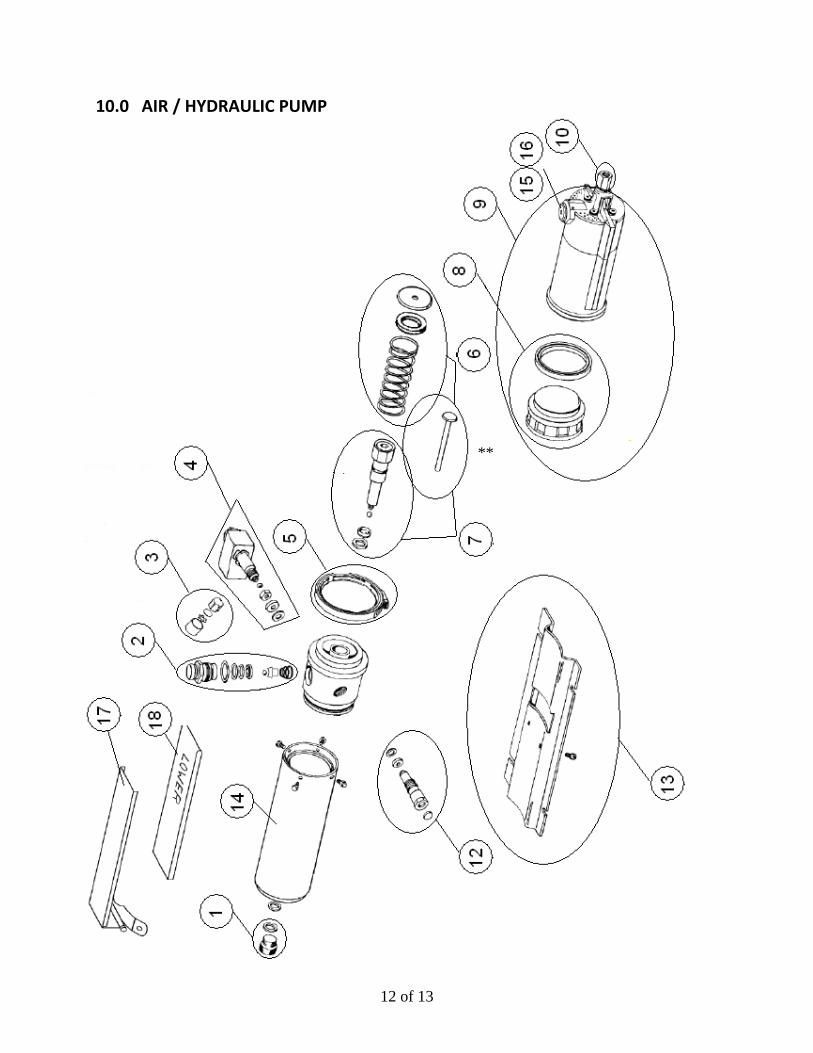
10.0 AIR / HYDRAULIC PUMP
**

13 of 13
ITEM QTY. DESCRIPTION PART # 1 1 RESEVOIR CAP ASSEMBLY 6‐3348 2 1 RELEASE GUIDE ASSEMBLY 6‐3349 3 1 FLOW RESTRICTOR ASSEMBLY 6‐3350 4 1 COUPLER ASSEMBLY 6‐3351 5 1 COUPLING V‐RETAINER 6‐3352 6 1 PLUNGER & SPRING KIT 6‐3353 7 1 HYDRAULIC CYLINDER ASSEMBLY 6‐3354 8 1 AIR PISTON ASSEMBLY 6‐3355 9 1 AIR MOTOR ASSEMBLY 6‐3356 10 1 COUPLER KIT 6‐3357 12 1 RELIEF VALVE ASSEMBLY 6‐3359 13 1 BASE 6‐3360 14 1 RESERVOIR 6‐3361 15 1 POPPET GUIDE ASSEMBLY 6‐3365 16 1 BOOT 6‐3368 17 1 HANDLE 6‐3366 18 1 RUBBER SLEEVE 6‐3367
** Plunger is included in both kits 6‐3353 and 6‐3354.