Addendum 5 - panynj.gov · RFP# 55667 – ADDENDUM# 5 2 Please Note: The date for receipt of...
27
Procurement Department 150 Greenwich Street 4 World Trade Center, 21 st Floor New York, NY 10007 January 17, 2019 SUBJECT: REQUEST FOR PROPOSALS FOR PERFORMANCE OF EXPERT PROFESSIONAL ARCHITECTURAL AND ENGINEERING SERVICES FOR THE PATH REPLACEMENT OF SUBSTATION NO. 2 ON AN “AS- NEEDED” BASIS DURING 2019 THROUGH 2024 (RFP# 55667) – ADDENDUM #5 Dear Sir or Madam: The following questions were received from RFP recipients. The questions and the corresponding Authority answers are provided for your information and use, as appropriate. Question #1: The Attachment A, Page 2, Section II. Scope of Work, Scope of Work, second paragraph, states that the building shall be designed as a “two (2) levels, non-inclusive of roof areas, totaling approximately 31,000 gross square feet”, and that the design shall take into consideration for a future building level. Based on the review of the documents, is a third floor option still being considered and how should this be reflected in the cost of the professional services being requested? Answer #1: The future third floor level shall be considered in the structural design of the superstructure and foundation. The selected consultant is expected to work with the Authority’s Structural Engineers to establish design criteria for this future third floor level during the early design phase. Question #2: The “Utility Connection Feasibility Analysis” report stated there are several options outlined for connecting the utilities into the tunnel systems. Has a preferred option been determined? Answer #2: The selected consultant shall review the Utility Connection Feasibility Analysis Report and recommend options for connecting the utilities into the tunnel systems at 25 % submission. The Authority and the selected consultant shall work together to decide the preferred option for the utility connection after 25% submission review. Refer to Section III. Task F. in the Attachment A, pages 22 & 23, items 7.b. and 7.f. Question #3: The Attachment A, Section III., Task I., items 12 and 13 reference Specification 260132 (top of page 34) for the substation electrical O&M Manuals. Is there a specification that can be provided that outlines the requirements for O&M Manuals for Mechanical systems, similar to that for substation equipment? In addition, can you provide standard language or an approved sample for the referenced Specification 260132? Answer #3: The Specification 260132, “Operation and Maintenance Manuals” specifies the requirements for the preparation of operation and maintenance (O&M) manuals including heating, ventilation, air conditioning (HVAC) and clean agent fire suppression system-FM200. The selected consultant shall revise the section to include all mechanical systems related to this project as compressed air system. This is a Customized Specification (C-Spec) that the selected consultant shall develop. See attached for a sample.
Transcript of Addendum 5 - panynj.gov · RFP# 55667 – ADDENDUM# 5 2 Please Note: The date for receipt of...

Procurement Department 150 Greenwich Street 4 World Trade Center, 21st Floor New York, NY 10007
January 17, 2019 SUBJECT: REQUEST FOR PROPOSALS FOR PERFORMANCE OF EXPERT
PROFESSIONAL ARCHITECTURAL AND ENGINEERING SERVICES FOR THE PATH REPLACEMENT OF SUBSTATION NO. 2 ON AN “AS-NEEDED” BASIS DURING 2019 THROUGH 2024 (RFP# 55667) – ADDENDUM #5
Dear Sir or Madam:
The following questions were received from RFP recipients. The questions and the corresponding Authority answers are provided for your information and use, as appropriate.
Question #1: The Attachment A, Page 2, Section II. Scope of Work, Scope of Work, second paragraph, states that the building shall be designed as a “two (2) levels, non-inclusive of roof areas, totaling approximately 31,000 gross square feet”, and that the design shall take into consideration for a future building level. Based on the review of the documents, is a third floor option still being considered and how should this be reflected in the cost of the professional services being requested?
Answer #1: The future third floor level shall be considered in the structural design of the superstructure and foundation. The selected consultant is expected to work with the Authority’s Structural Engineers to establish design criteria for this future third floor level during the early design phase.
Question #2: The “Utility Connection Feasibility Analysis” report stated there are several options outlined for connecting the utilities into the tunnel systems. Has a preferred option been determined?
Answer #2: The selected consultant shall review the Utility Connection Feasibility Analysis Report and recommend options for connecting the utilities into the tunnel systems at 25 % submission. The Authority and the selected consultant shall work together to decide the preferred option for the utility connection after 25% submission review. Refer to Section III. Task F. in the Attachment A, pages 22 & 23, items 7.b. and 7.f.
Question #3: The Attachment A, Section III., Task I., items 12 and 13 reference Specification 260132 (top of page 34) for the substation electrical O&M Manuals. Is there a specification that can be provided that outlines the requirements for O&M Manuals for Mechanical systems, similar to that for substation equipment? In addition, can you provide standard language or an approved sample for the referenced Specification 260132?
Answer #3: The Specification 260132, “Operation and Maintenance Manuals” specifies the requirements for the preparation of operation and maintenance (O&M) manuals including heating, ventilation, air conditioning (HVAC) and clean agent fire suppression system-FM200. The selected consultant shall revise the section to include all mechanical systems related to this project as compressed air system. This is a Customized Specification (C-Spec) that the selected consultant shall develop. See attached for a sample.

RFP# 55667 – ADDENDUM# 5
2
Please Note: The date for receipt of proposals for the subject RFP remains 2:00 P.M. on January 25, 2019.
If you have any questions, please contact Ms. Ekatherina Carrera at [email protected].
Sincerely, David Gutiérrez Assistant Director Procurement Department
C 09/26/18
DIVISION 26
SECTION 260132
OPERATION AND MAINTENANCE MANUALS
PART 1 - GENERAL
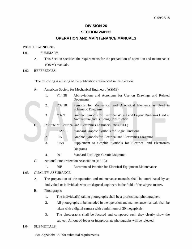
1.01 SUMMARY
This Section specifies the requirements for the preparation of operation and maintenance
(O&M) manuals.
1.02 REFERENCES
The following is a listing of the publications referenced in this Section:
American Society for Mechanical Engineers (ASME)
1. Y14.38 Abbreviations and Acronyms for Use on Drawings and Related
Documents
2. Y32.18 Symbols for Mechanical and Acoustical Elements as Used in
Schematic Diagrams
3. Y32.9 Graphic Symbols for Electrical Wiring and Layout Diagrams Used in
Architecture and Building Construction
Institute of Electrical and Electronics Engineers, Inc. (IEEE)
1. 91A/91 Standard Graphic Symbols for Logic Functions
2. 315 Graphic Symbols for Electrical and Electronics Diagrams
3. 315A Supplement to Graphic Symbols for Electrical and Electronics
Diagrams
4. 991 Standard For Logic Circuit Diagrams
National Fire Protection Association (NFPA)
1. 70B Recommend Practice for Electrical Equipment Maintenance
1.03 QUALITY ASSURANCE
The preparation of the operation and maintenance manuals shall be coordinated by an
individual or individuals who are degreed engineers in the field of the subject matter.
Photographs
1. The individual(s) taking photographs shall be a professional photographer.
2. All photographs to be included in the operation and maintenance manuals shall be
taken with a digital camera with a minimum of 20 megapixels.
3. The photographs shall be focused and composed such they clearly show the
subject. All out-of-focus or inappropriate photographs will be rejected.
1.04 SUBMITTALS
See Appendix “A” for submittal requirements.

PART 2 - PRODUCTS
2.01 GENERAL REQUIREMENTS
Description
1. The operation and maintenance manual, hereinafter referred to as "the manual,"
shall be prepared in such a manner to contain the necessary information and to
convey the philosophy necessary to enable the reader to understand the procedures
and all other requirements for the proper operation, maintenance, and
troubleshooting of the system(s) and equipment described therein.
2. The reader of the manual shall be assumed to be technically competent but totally
unfamiliar with the systems and equipment described therein.
3. In addition to the description of the operation, maintenance, and troubleshooting
instructions, the manual shall contain the following information on the system(s)
and equipment described therein:
All Shop Drawings and As-Built Drawings.
All Catalog information for the equipment furnished and installed.
A list of all references utilized to prepare the information contained in the
manual.
Required Confidential classification, if necessary.
Preliminary Edition, Draft Copies and Final Review
1. The Preliminary Edition, all Draft copies, and the Final Review shall be 100
percent completed copies of the manual, and shall be prepared in the same manner
as the Final Edition with the exception of the preparation of the binding and cover
page.
After the manual is completed, it shall be submitted for review and
designated as "PRELIMINARY EDITION." All comments generated by
the Engineer shall be incorporated and resubmitted in the subsequent draft
copy.
Once all comments are incorporated and all errors and omissions are
corrected, the Engineer will request that another submission be made by
the Contractor, and it shall be marked "FINAL REVIEW." After a review
by the Authority, the Contractor shall incorporate all comments and
correct all errors and omissions as directed by the Engineer.
2. The Preliminary Edition, all Draft copies, and the Final Review shall be bound
using a black plastic comb binding and a clear, transparent plastic cover and rigid
plastic back cover. The thickness of the plastic cover shall be 20-gauge, minimum.

3. The cover page of the Preliminary Edition, all Draft copies, and the Final Review
shall be a copy of the Title Page, designed in accordance with the requirements of
this section.
4. Cover page shall be printed on light blue, 65-pound stock and shall measure 8-1/2
inches by 11 inches.
Organization
1. The manual shall be organized logically into the following sections layout and
content of the chapters and/or subsections shall be prepared in accordance with the
following:
Introduction
Shall include the Introductory Chapter.
Shall identify the facility; the systems described in the manual,
along with a brief introduction and the page location of all the
manual sections and chapters.
System Description and Operation
This section shall describe the system and all aspects of its
operation including sub-systems and components.
Chapters shall be organized in a manner to logically describe the
system. Examples of logical break points may involve different
structures, or buildings and/or locations, sub-systems, or major
components.
The manual shall include a detailed description of all procedures
for all modes of operation.
Recommended Maintenance Procedures
Maintenance guidelines shall be included to instruct regarding the
safe, reliable operation of the equipment throughout its service
life.
Guidelines shall be based upon manufacturer's recommendations;
Port Authority standards, manuals, and maintenance rosters; and
all appropriate industry standards.
Troubleshooting Guidelines
In-depth troubleshooting procedures shall be included for all
systems and equipment.
The manual shall include written descriptions of typical problems
which may occur, possible causes of these conditions, and the
step-by-step corrective measures required to correct each
possibility.

Illustrations
The illustrations used in the manual shall include all drawings and
photographs required to properly document the information and
visually describe the subject matter presented therein.
Illustrations that are not photographs shall be considered drawings
and prepared accordingly.
Abbreviations and Symbols
All abbreviations and symbols utilized shall comply with ASME
Y32.18, ANSI Y32.9, ASME Y14.38, IEEE 91/91A, IEEE 315,
IEEE 315A, AND IEEE 991.
All abbreviations and symbols used in the manual shall be unique,
and no conflict shall exist among them.
As-Built Drawings
As-Built drawings shall be prepared for inclusion in the manual to
accurately portray the systems after all construction has been
completed and after the systems are operating to the satisfaction
of the Engineer. An index shall be provided that itemizes all of
the As-Built drawings.
Shop Drawings
All approved shop drawings for all of the equipment supplied
and/or installed for the system described in the manual shall be
included in the manual. An index shall be included for all shop
drawings that tabulate all equipment by type and model number.
An index shall be included that identifies the different types,
including model numbers, of equipment present, listed in
alphabetical order. Each entry shall refer to the appropriate shop
drawing(s) and the page numbers where they are located.
Catalog Information
A sample of the catalog information shall be provided for all
equipment furnished and/or installed under this Contract. An
index shall be included that identifies the different types,
including model numbers, of equipment present, listed in
alphabetical order. Each entry shall refer to the appropriate
catalog cut(s) and the page numbers where they are located.
References

A list of references shall be included identifying the sources of all
the information contained in the manual. The list shall identify
the nature of the information and where it was used in the manual.
Text and Paper
1. The manual shall be printed in the Times New Roman typeface family using a 12-
point font.
2. With the exception of the drawings, diagrams, and photographs, all information
shall be printed on 8-1/2 by 11 inches, 24-pound white bond paper utilizing a
portrait format.
Photographs
1. Photographs shall show various views of all equipment in the system with all
assemblies, subassemblies, and components identified through the use of call-outs.
2. Wherever possible, photographs shall be taken in the vertical, or portrait format,
with the subject centered horizontally and vertically. Adequate space shall be
provided on all sides between the subjects and the borders of the photograph to
facilitate placing call-outs for the respective components.
3. The photographs shall be treated as figures and shall be referred to in the text to
assist in conveying the necessary information to the reader. The figures shall be
designated using a two-number format separated by a period (e.g. Figure 1.2). The
first number indicates the chapter in which the photograph is first referred to, and
the second is a sequential number indicating its position in the total referenced
figures in that chapter.
4. Photographs shall be enlarged and cropped to a finished size of approximately 7
inches by 9 inches, and shall be placed on a page with margin.
5. A title area shall be provided to accurately describe the subject of the photograph.
The title area shall be composed of the figure number and a two-line title.
The first line shall be a description of the photograph's subject. The second
shall contain information on the equipment's location and/or details of the
photograph's composition (e.g. side view, rear view, section). No title
shall exceed three lines.
The title area shall be 6-3/4 inches by 1/2 inch high.
Text for title areas shall be 12-point, Bold font, upper and lower case on
white bond paper background.
6. All photographs shall include call-outs identifying the relevant equipment and/or
components that are being described in the text which refers to the photograph.

Each call-out is to be cut straight and squared on all four sides leaving
about 1/16-inch white space above top line, below bottom line, to the left
of the widest line and to the right of the widest line.
Text for call-outs shall be in 8-point font, using upper and lower case.
Equipment that is being called out shall not be covered by a call-out.
Edges of call-outs shall not be closer than 1/8 inch to the borders of the
photograph.
Arrows for call-outs shall be self-stick, black, and with single-sided white
trim.
All call-outs shall identify items by their functional names, regardless of
what the manufacturer, drawing, decal, catalog, or personnel indicate (i.e.
mode selector switch, motor control switch).
Specific designations in call-outs shall be continuous. There shall be no
space within a designation. If designation involves multiple elements, use
dashes between these elements. Ratings or other data shall be separated
from the designation by a comma.
7. Completed photographs, or those with call-outs and arrows applied, shall be
digitally copied and submitted on a read-only CD. Alternate methods of
reproduction may be used, but only after prior approval by the Engineer.
2.02 FORMAT
Binder
1. General
The first six sections of the manual form an integral document and shall
be contained in one binder when possible.
If multiple volumes are required, each volume shall include the list of
references as the last section. The section number shall be retained, and
the Table of Contents shall also include this information.
2. Construction
Binders shall be standard three-ring booster construction made of 90-
gauge Linear Polyethylene. "Microdyne" cover type material is not
acceptable.
Binding mechanism shall be secured to the cover by two colored rivets
installed 1 inch from the top and bottom edges of the seam. The color of
the rivets shall match the color of the binder.
3. Cover Page
The Engineer shall provide the light blue color of the manual prior to
printing the first Draft Copy.

The cover page shall clearly identify the number of the manual, the
facility, and the title of the systems being described. All information shall
be presented as described below, and shall be silk-screened to the binder.
The PATH Letter Logo in 3/8 inch high black lettering 1/2 inch
from the top of the cover and flush with the right margin.
The facility logo shall be black lettering and shall be placed 3/4
inch below the PATH Letter Logo and flush with the right margin.
The number of the manual shall be in black 75-point Bold font,
and placed 1 inch below the facility logo and flushed left.
The name of the facility shall be placed 3/8-inch to the right of the
manual number using a white outline font 1/2 inch high on two
separate lines. The complete title shall be balanced between the
two lines in a manner that results in approximately equal line
lengths. The facility title shall be placed such that the top line is
flush with the top of the manual number and the bottom line is
flush with the bottom of the number.
The words Operation and Maintenance shall be placed 1/2 inch
below the manual number and flush with the left margin using
3/16-inch high black letters in lowercase.
The title of the manual shall be placed 1/2 inch below the words
"Operation and Maintenance" using white 3/4 inch high lowercase
letters. The title lines shall be spaced approximately 1 inch apart.
The title shall be balanced between as many lines as possible, up
to the 1-1/8-inch margin at the bottom of the binder.
Information on Binder Spine
The title of the manual shall be printed in 3/16 inch white
lowercase lettering running vertically on the spine from 1/4 inch
from the top rivet running down to a maximum length of 6 inches.
If title description requires additional space, balance the title
between two lines.
The number of the manual shall be shown using white numbers
3/8-inch high and placed 1/4 inch above the bottom rivet.
The Authority's standard two- or three-letter abbreviation of the
facility shall be in white and shall be centered 3/8 inch above the
center of the bottom rivet, with a minimum offset from the rivet
of 1/4 inch.

The binder shall be no larger than 2 inches. In the event that the
information presented cannot fit in a 2-inch binder, then multiple volumes
shall be utilized.
Multiple volumes shall be prepared so that the information
presented in each volume stands on its own in order to minimize
referrals to other volumes.
The volume designation shall be located 3/8 inch above the
facility letter designation.
The breakdown of information for multiple volume manuals shall
be submitted to the Engineer for approval.
Title Page
1. The title page shall be the first page of the manual, and shall contain the following
information and be formatted in accordance with the requirements of this Section.
The facility title shall be in bold ¼-inch lettering using all capitals and be
the first line of text on the page. Text shall be flush with the left margin
leaving an approximately 1-3/8-inch margin at the top of the page.
The wording "Manual No. X" shall be placed approximately 1/4 inch
below the facility title. The facility manual number shall be provided by
the Engineer.
At approximately 1 inch below the manual number line, the following
wording shall appear "Operation and Maintenance of."
The title of the manual shall be placed 7/16-inch below c. above and appear
in bold using all lower-case. Title shall occupy as many lines as necessary
to be printed within the specified margins.
The PATH letter logo shall be centered at the bottom of the page leaving
a bottom margin of approximately 1 1/4 inches.
The following three lines shall appear sequentially such that the last line
is approximately ¾-inch above the PATH letter logo. The month and year
shall indicate the month and year that the Authority received the final
edition.
Final Edition
Engineering Department
Publication, Month year
Title page shall be 36-pound, 8-1/2-inch by 11-inch white paper.
Foreword
1. The Foreword shall be prepared as described below.
The text shall be justified with 1-3/4-inch left and right margins.

The word "F O R E W O R D" shall appear approximately 2 1/2 inches
from the top edge of the paper in bold capitals with a space between each
letter and flush with the left margin.
The first paragraphs shall be below the word Foreword separated by a
blank line. Subsequent paragraphs shall be also be separated by a blank
line.
The page number in lower case roman numbers ("iii") shall be centered,
approximately 11/16 inch from the bottom of the page.
Text for the Foreword shall be restricted to one side only. No printing will
be allowed on the back of the page(s).
Table of Contents
1. The Table of Contents shall be prepared as described below.
All text shall be in 12-point font with a left margin of 1 3/4 inches and a
right margin of 1 1/4 inches.
The word "C O N T E N T S" shall appear in italics using bold capitals,
centered over the text approximately 1 inch from the top of the page.
Chapter Identification
Two lines below Item b, the words "Chapter" and "Page" shall
appear in italic, underlined and flush with the left margin and right
margins respectively.
All chapters in the manual shall be itemized using the Chapter
number and title on the same line with a 1/2-inch space between
the two. A blank line shall separate each chapter entry.
Chapter titles shall be shown in capitals while the chapter numbers
shall be centered under the heading "Chapter".
All sections of each chapter shall be itemized below their
respective chapter after leaving a blank line. Each section title
shall appear in title case along with the page number on which it
begins. Section titles shall appear flush with the margin created
with the first letter of the chapter title and separated from the page
numbers by a series of periods at every 1/8 inch until
approximately 5/16 inch before the page number. The page
number shall be centered under the heading "Page."
All subsections shall be itemized under their respective sections
and placed flush with a left margin indented 1/2 inch from the
chapter title margin.

All pages for the Table of Contents shall be numbered sequentially in
roman numerals starting with "v." The page numbers shall be in italics
and centered at approximately 3/4 inch from the bottom of the page. A ¾-
inch blank space shall separate the page designation from the last entry on
the page.
Printing shall be on both sides of the page, with blank pages inserted for
proper pagination.
Chapters
1. Width of text for all paragraphs shall be 5 1/2 inches and justified such that the left
and right margins will be 1 1/2 inches.
2. Line spacing shall be set at 1 1/2 for improved readability.
3. Page Numbers
Page Numbers shall be centered 3/4 inch from both the bottom of the page
and the last line of text on the page.
Page numbers shall be comprised of two numbers separated by a dash.
The first number indicates the number of the respective chapter and the
second is the sequential page number within that chapter.
4. Each chapter shall begin on a new page and contain the chapter number and title.
Chapter designations shall be all capitals and in the following format,
"CHAPTER X" where X is the chapter number. Chapter designations
shall be centered 1 inch from the top edge of the page.
Chapter titles shall appear in all capitals centered and two lines below the
Chapter designation. If chapter title requires more than one line, the line
spacing shall be unity.
Chapter, section and paragraph titles or headings shall be descriptive of
the contents of the division they head.
5. Each chapter shall be broken up into sections that segregate the information being
presented into logical units.
Section titles shall be in all capitals and be centered two lines from the
preceding paragraph. The first section title shall be separated vertically by
four blank lines from the Chapter title. If the title requires more than one
line of text, the line spacing for the title only shall be unity.
The first two sections shall be designated as "SCOPE" followed by
"GENERAL." Additional sections shall be included as needed and labeled
to properly convey the information contained therein.
Subsections shall be utilized to further segregate the information.
Subsection titles shall be flush with the left margin in title case. The title

shall be uniformly divided into lines such that no single line contains
information that is wider than 2-1/2 inches. Two blank lines shall separate
the title from the preceding paragraph. The first successive paragraph shall
be separated from the title by one blank line.
Section Units shall be utilized to further segregate subsections. Unit titles
shall be in upper and lowercase, underlined and ended with a period. The
title shall be the first item of the paragraph line and be properly indented.
The first paragraph shall begin on the same line as the title and shall be
separated by two blank lines from the preceding paragraph.
6. Steps Describing a Particular Procedure
All procedures described shall be itemized in the numerical sequence (i.e.
1, 2, 3, etc.) in which they are to be performed to achieve the desired
results.
Step descriptions shall be indented 1/2 inch from the step number and
ended with a period.
Steps that require multiple lines of text shall be formatted such that all
lines of text are left justified to the text on the first line.
7. Data Tables
All data shall be tabulated.
Data tables requiring less than one-half a page shall be part of the text.
Data tables requiring more than one-half a page shall be treated as a figure
and prepared along the guidelines specified in this Section.
Data shall be tabulated under headings that properly describe the
information presented in that column.
Abbreviations
1. All abbreviations and designations used in the manual, including drawings,
illustrations and catalog cuts, shall be in tabulated and alphabetical order.
Writing Style
1. The writing used shall be free of vague and ambiguous terms, using the simplest
words and phrases to convey the intended meaning and information. Sentences
shall be short and concise.
2. All essential information shall be included, either by direct statements or by
reference.
3. Punctuation shall be used in a manner that aids in reading and prevents misreading.
Well-planned word order requires a minimum of punctuation. When extensive
punctuation is used for clarity, sentences shall be rewritten.
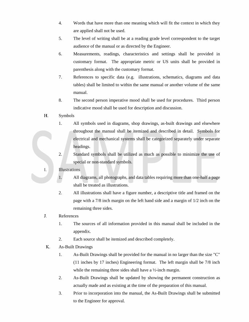
4. Words that have more than one meaning which will fit the context in which they
are applied shall not be used.
5. The level of writing shall be at a reading grade level correspondent to the target
audience of the manual or as directed by the Engineer.
6. Measurements, readings, characteristics and settings shall be provided in
customary format. The appropriate metric or US units shall be provided in
parenthesis along with the customary format.
7. References to specific data (e.g. illustrations, schematics, diagrams and data
tables) shall be limited to within the same manual or another volume of the same
manual.
8. The second person imperative mood shall be used for procedures. Third person
indicative mood shall be used for description and discussion.
Symbols
1. All symbols used in diagrams, shop drawings, as-built drawings and elsewhere
throughout the manual shall be itemized and described in detail. Symbols for
electrical and mechanical systems shall be categorized separately under separate
headings.
2. Standard symbols shall be utilized as much as possible to minimize the use of
special or non-standard symbols.
Illustrations
1. All diagrams, all photographs, and data tables requiring more than one-half a page
shall be treated as illustrations.
2. All illustrations shall have a figure number, a descriptive title and framed on the
page with a 7/8 inch margin on the left hand side and a margin of 1/2 inch on the
remaining three sides.
References
1. The sources of all information provided in this manual shall be included in the
appendix.
2. Each source shall be itemized and described completely.
As-Built Drawings
1. As-Built Drawings shall be provided for the manual in no larger than the size "C"
(11 inches by 17 inches) Engineering format. The left margin shall be 7/8 inch
while the remaining three sides shall have a ½-inch margin.
2. As-Built Drawings shall be updated by showing the permanent construction as
actually made and as existing at the time of the preparation of this manual.
3. Prior to incorporation into the manual, the As-Built Drawings shall be submitted
to the Engineer for approval.

4. An index shall be provided that itemizes all As-Built Drawings listed by drawing
number and title.
Shop Drawings
1. All Shop Drawings shall be provided for the manual in no larger than the size "C"
(11 inches by 17 inches) Engineering format. The left margin shall be 3/4 inch
and 1/2 inch for the remaining three sides.
2. All Shop Drawings required under the Contract for the system(s) being described
in the manual(s) shall be included.
3. An index shall be provided that itemizes all Shop Drawings by equipment type,
title and identifies the location and designation of the equipment the drawings
pertain to.
Catalog Cuts
1. Catalog information shall be included for all types of equipment in the system(s).
The information shall include, at a minimum:
Manufacturer
Equipment Type
Model Number
Technical Specifications
Any other information required for the proper technical application of the
equipment.
2. In addition the following catalog information shall be included:
Title
Publishing Date
Serial Number
Page numbers for each specific type of equipment.
3. All catalog cuts required under the Contract for the system(s) being described in
the manual shall be included.
4. Catalog cuts shall be provided on 8 1/2-inch by 11-inch paper with a minimum of
a 3/4-inch margin on the left hand-side suitable for binding in a standard three-ring
binder. A minimum border of 1/2 inch shall be maintained on the remaining three
sides.
5. Pages shall be identified by the type of equipment to which it refers and by the
sequential page number of the manual(s).
6. An index shall be provided at the beginning of the section itemizing all catalog
cuts by type of equipment, page number and physical locations where that type of
equipment is installed.

2.03 CONTENT
The following sections shall be prepared according the format specified above and shall
include, at a minimum, the following information.
1. Foreword - The Foreword shall contain the following information:
The purpose of the manual and to what system and facility the information
applies.
All other Port Authority manual or standards that may apply to the
operation and maintenance of the subject system(s).
The entities responsible for the preparation of the manual.
Qualifying information presented in the manual.
2. Introductory Chapter
The introduction shall be broken down into a minimum of four subchapters
designated as SCOPE, GENERAL, NOTES, and APPENDICES.
The SCOPE shall outline the subject matter and function of the manual.
All chapters shall be identified and described briefly.
GENERAL shall contain a general description of the system and any
background information that may be required to fully understand the
information being presented.
Other sections may be required to summarize the interaction of other
systems with the systems described in the manual.
NOTES and APPENDICES shall be the last two subchapters in the
Introductory Chapter, and shall be identified and described briefly.
A statement of the warranty provisions, and contact information for
warranty service, for each device shall be included in each equipment
manual.
A list of the recommended spare parts, including OEM part or assembly
catalog numbers, shall be included.
3. Chapters On System Description and Operation
General
The information contained in the manual(s) shall include, at a
minimum, the information specified herein.
Items to be identified in this section are typical requirements for
the systems identified. The information shall be properly located
in the respective sections of the manual, and prepared in
accordance with the requirements of this Section.
All chapters shall be divided into subchapters which shall in turn
be further divided into sections as described herein in order to

convey the information in a modular format that is accurate and
clear. The first two subchapters shall be designated as SCOPE
and GENERAL respectively. These first subchapters shall not be
broken down into sections.
The SCOPE shall summarize the subject matter contained in each
of the respective chapters. GENERAL shall contain a synopsis of
the system(s) being described and how the information is
presented including a breakdown of the subchapters.
The quantity and breakdown of the chapters shall be made in a
manner such that the information is presented in a modular, logical
format for conciseness and clarity. Quantity and breakdown of
the chapter shall be submitted to the Engineer for approval prior
to the preparation of the manual.
The information contained in the chapters for a particular type of
system shall begin with an overall description followed by an in-
depth explanation of the theory of operation. Information shall be
provided in sufficient quantity and clarity that the reader will be
able to understand the principles, proper operation,
troubleshooting, and maintenance procedures of the system and
all system components. Appropriate references shall be made to
the respective illustrations and references.
System and sub-system operation shall be described in sufficient
detail and clarity for complete and proper operation of the entire
system. The operating instructions shall include all the procedures
necessary to enable operating personnel to efficiently and
effectively use the system(s) and equipment in accomplishing the
systems’ designated task(s). A numbered step-by-step method
shall be utilized to describe proper operational sequences.
All system components and proper system component operation
shall be described in complete detail, including the system
component’s functional name designation, location, and intended
function. All major sub-components and sub-assemblies shall be
described in detail.
The physical layout of the system(s) shall be shown on a facility
plan that accurately pinpoints system component locations.
Appropriate floor plans and location diagrams shall be included
for each of the systems and all equipment. Component references

for the same type of equipment shall be consistent throughout the
manual.
All equipment controls and indications shall be identified, located
and functions described. All modes and the proper settings shall
be identified, itemized and described completely. The use and
relative advantage of each mode shall be described including
references to the appropriate logic diagrams and schematics.
All specialized test equipment required for the proper
maintenance and troubleshooting of the system(s) shall be
described in accordance with the requirements of this Section.
All manuals or guides required to be submitted to the Engineer by
the Contract for the system being constructed shall be included in
the appendix.
Factory and Field (As-Built) Schematics diagrams shall be
included for each type of equipment included in the system(s)
being described. Schematics shall be color coded, and identify all
interconnections.
Electrical Distribution Systems
A one-line diagram shall be provided which identifies all sources
and load centers connected to the system. Device information
shall include pertinent ratings for that type of equipment. Device
designations shall conform to IEEE standards.
Location plans shall be shown for all electrical distribution
equipment including conduit runs and ductbanks.
Systems shall be described beginning with the incoming service
or other equipment providing the necessary power. The balance of
the equipment shall be addressed in manner that is consistent and
correlated with the one-line diagram.
All devices shall have the nameplate information properly
documented.
Point-to-point wiring for all control wiring and terminal strips
shall be included and described in sufficient detail to convey the
proper operation of the equipment.
All terminal strips/cabinets shall have their terminals tabulated.
The tabulation shall include terminal numbers, the device
controlled or monitored, the function performed, and the
indication provided.

All key interlocks shall be shown and documented on a Key-
Interlock Diagram. The diagram shall show the key blocks of all
devices having key-interlocks along with the key designations
superimposed on a one-line of the system. The Key-Interlock
diagram shall indicate, using dashed lines, the sequence for proper
key insertions.
All relays shall have their contacts described in detail and
enumerated for function and proper operation.
All control circuits for each type of equipment shall be described
in detail. Schematics shall show all power sources, input and
output functions and point-to-point wiring.
All equipment shall be described in detail. The information
should include photographs, diagrams, drawings, schematics and
all other information required to convey its proper operation and
function, maintenance and troubleshooting requirements.
The photographs for each type of equipment shall include, at a
minimum, the following views: overall, interior views showing
major mechanisms and components.
Control Systems
All control systems shall be depicted using a block diagram.
Connections and logic flow shall be indicated along with all
interfaces to other external systems.
All control devices and wiring shall be documented using standard
Joint Industry Council (JIC) Schematic Ladder diagrams. All
lines shall be sequentially enumerated on the left-hand side. On
the right-hand side the function of the device or circuit shall be
shown along with the line references to where the device contacts
are connected. If the contacts are normally closed, they are to be
underlined. Each function or device shall be shown on a different
line.
All system equipment shall be shown on plan drawings of the
physical plant.
The system operation shall be described in complete detail
including all annunciation and control functions.
Logic diagrams shall be used to convey the sequence of proper
operation and control

JIC standard schematic ladder diagrams shall be utilized to
document all control circuits and associated functions.
All components and sensors shall be described in detail in terms
of function, proper operation, physical and electrical
characteristics.
System components shall be described in detail including
information on the signals as well as the physical media used for
transmission.
Heating, Ventilation, Air Conditioning (HVAC)
The system shall be described in complete detail along with the
theory of operation. System capabilities and characteristics shall
be covered in detail.
A block diagram and a schematic control and flow diagram of the
entire system shall be included to assist in describing the system
as well as to convey the interrelation between the different
subsystems.
The refrigeration system shall be described in detail. Control and
flow diagrams shall show all system components such as the
compressor, expander, heat exchanger and the distribution system
connecting these items. Diagram connections shall indicate the
normal flow between the subsystems. Photographs shall document
all equipment including all necessary internal views. Schematics
shall be included to document all power and control circuits.
The air movement system shall be described in detail. Control and
flow diagrams and schematics shall show all system components
including motors, fans and the resulting ductwork to the utilization
space. Schematic connections shall indicate the normal flow
between all subsystem components. Photographs shall document
the different types of equipment including overall and appropriate
internal views.
Clean agent fire suppression system-FM200
The system shall be described in complete detail along with the
theory of operation. System capabilities and characteristics shall
be covered in detail.
A schematic control wiring diagram of each zone shall be
prepared to assist in describing the system as well as to convey the

interrelation between the different systems such as fire alarm
system and HVAC system.
The Clean Agent system shall be described in detail. Each zone
control wiring diagrams shall show all system components such
as the control panel, smoke detectors, alarm strobes, emergency
power off, purge panel, manual release, main to reserve switches
and other components required for a complete system operations.
Photographs shall document all equipment including all necessary
internal views. Schematics shall be included to document all
power and control circuits.
Manual functions, (purge panel and keys, manual release pull
stations abort push button, main ti reserve switch, etc.) shall be
described and how they interface with the balance of the system.
All types of system functions and capabilities shall be categorized
and described in detail. The description shall include how the
function is accomplished and reference the system components
that are involved in providing these functions including interfaces
with the fire alarm system and HVAC purge system.
Security Systems
All security systems shall be depicted using schematic block
diagrams. The diagrams shall include the entire system and
indicate all sub-system components. Connections and interfaces
to other external systems shall also be shown.
All system equipment shall be shown on plan drawings of the physical plant. Tables
that itemize all system equipment broken down by physical location (e.g. building,
room, etc.) and type of equipment shall be included. Tables shall show the quantity
and designation of each type of equipment at that respective location.
The system operation shall be described in complete detail
including all annunciation and control functions. Descriptions of
all system inputs and the resultant outputs generated by the system
shall be included. Tables shall be utilized as much as possible in
order to present the information in a clear and concise manner.
Logic flow diagrams shall be used to describe the sequence of
proper operation. Flow diagrams include system inputs, control
functions and all associated annunciations and outputs.
The means and types of identification used shall be identified and
described in detail in terms of theory and actual operational
requirements.

All levels of access shall be described in detail in terms of philosophy, theory of
operation (including interfaces with the system) and actual operational restrictions
(e.g. access areas, etc.)
All manual access functions, (manual locks and keys, etc.) shall
be described and how they interface with the balance of the
system.
All system functions and capabilities shall be categorized and
described in detail. The description shall include how the function
is accomplished and reference the system components that are
involved in providing these functions including interfaces with
computer hardware and software. Block diagrams shall be
included to show typical inputs and outputs of the system for each
type of function identified.
All categories of data used to characterize all equipment shall be
identified and described. Description shall include reference to
how this data is used by the system to accomplish the intended
functions (e.g., identification, access, control, etc.)
All software required for the proper operation of the system shall
be described in detail. A User's Guide shall be included in the
appendix for the Host Software Application. A complete
programming manual from the original software publisher shall
be included in the appendix. The programming manual shall
include complete instructions and sample programming for the
functions required by the Contract Documents.
Communication Systems
All communication systems shall be depicted using block
diagrams and schematics. The diagrams shall comprise the entire
system and convey all sub-systems. Connections and logic flow
shall be indicated along with all interfaces to other external
systems.
As-Built wiring diagrams and schematics showing point to point
(pin to pin) wiring shall be included for all electronic interconnect,
audio, video, and control system wiring.
As-Built Run sheets or field wiring drawings shall be included to
document all system communication lines and interconnections
and included in the appendix.

The manual shall include descriptions, photographs and drawings
of: patch panel assignments, custom equipment modifications,
front panel layouts of equipment racks and mill work details.
Field installation wiring and cabling diagrams shall be included.
All cable and wiring terminations shall be shown on the drawings
along with all terminal markings, cable connector markings and
cable lengths.
All equipment shall be described in detail. All appropriate
illustrations shall be included to properly convey to the reader the
proper operation, maintenance and troubleshooting of the device
accurately and concisely. All internal wiring and schematic
diagrams, parts list, gain charts, impedance charts shall be
included for each device. Electrical characteristics shall be
tabulated. All associated controls shall be explained in detail
including the nature and limits of these controls on the output
signal.
Interfaces and interconnections between the system and external
communication systems shall be described in detail.
Interconnection wiring and schematic diagrams shall be included.
All software required for the proper operation of the system shall
be described in detail, in terms of operational and programming
procedures. A User's Guide shall be included in the appendix for
the Host Software Application. Source code if supplied, shall be
listed in the appendix and described by subroutine and line-by-
line. A complete programming manual from the original software
publisher shall be included in the appendix. The programming
manual shall include complete instructions and sample
programming for the functions required by the Contract
Documents.
Fire Detection and Alarm Systems
All fire detection and alarm protection systems shall be described
completely using block diagrams and schematics. Block diagrams
and schematics shall be prepared and referenced as illustrations.
The diagrams shall describe the entire system and convey all sub-
systems. Connections and logic flow shall be indicated along with
all interfaces to other external systems.

One line riser diagrams shall be included for all systems described
in the manual. The riser diagram shall include all signaling
devices and alarm indicating devices, central fire command
stations, auxiliary fire command stations, local control panels,
portable programmers, power supplies, video display units,
printers, power supply, security hardware, and all other relays,
detectors, and interface modules necessary for total system
operation.
The system shall be described in sufficient detail to accurately and
concisely convey to the reader the proper operation, maintenance
and troubleshooting requirements of the entire system.
All software required for the proper operation of the system shall
be described in detail, in terms of operational and programming
procedures. Source code if supplied, shall be listed in the appendix
and described by subroutine and line-by-line. A complete
programming manual from the original software publisher shall
be included in the appendix. The programming manual shall
include complete instructions and sample programming for the
functions required by the Contract Documents.
Field wiring, routing and types shall be described in detail.
The stand-by power system shall be described in detail in terms of
its proper operation, maintenance and troubleshooting
requirements.
Electric Hoist
The hoist shall be described in complete detail including capacity, speed
and travel. Photographs shall document the equipment. Schematics shall
be included to document all power and control circuits.
Maintenance Schedules and Instructions
Maintenance schedules and instructions shall be provided for the
system(s) and for each type of equipment included in the
system(s). These procedures shall convey all the necessary
information required to maintain the system(s) and equipment
operating under the same reliability as when the equipment was
purchased.
The maintenance procedures shall incorporate information from,
but not necessarily be limited to, the following sources.

Original manufacturer's maintenance recommendations
All applicable industry standards (NFPA 70B, NFPA,
NEMA, IEEE, ASME, ANSI)
Existing Port Authority Operation and Maintenance
Manuals on similar systems and equipment as
coordinated by the Authority
Existing Port Authority Maintenance standards and
rosters as coordinated by the Authority
Existing procedures being performed by maintenance
staff as coordinated by the Authority
Where the manufacturer’s recommendations differ from industry
standards in a manner that its implementation would result in
either the equipment operating under decreased reliability or
violate the equipment's warranty, the manufacturer's
recommendations shall prevail.
Maintenance instructions shall include inspections, testing, and
overhaul of equipment, all procedures, instructions or both for the
performance of scheduled maintenance along with the
requirements for number of personnel, tools, consumable
materials, replacement parts and time required to perform each
maintenance routine. If applicable, references shall be made to
the appropriate illustrations (photographs and drawings) to ensure
that the reader fully understands the proper steps to be taken to
properly perform the recommended maintenance.
In addition to the scheduled maintenance, repair procedures for
potentially frequent problems and for the repairs identified in this
Section shall be included and prepared in accordance with the
requirements of this Section. These procedures shall be presented
in the same format as the maintenance procedures and provide as
a minimum all the information required to properly perform the
repair.
All maintenance and repairs shall be strictly limited to de-
energized equipment that has been taken off-line. The proper
procedures and safety precautions required to isolate and de-
energize the equipment shall be identified, enumerated and
described in complete detail.

Maintenance for electrical distribution system equipment
operating at voltages greater than 600V shall be described in such
a manner that its performance will be in strict adherence to the
Port Authority's High Tension Administrative and Safety Rules, a
copy of which is available for inspection at the Engineering
Department Design Division, Port Authority Technical Center,
241 Erie Street, Jersey City, NJ 07310-1397.
An index shall be provided at the beginning of the chapter
identifying the recommended maintenance or repair procedures
by title, type of equipment (including model number), and the
page(s) where information is located. The index shall be
organized in alphabetical order first by type of equipment and then
by title of maintenance/repair routine.
Prior to writing the maintenance instructions for the system(s) and
equipment described in the manual, a sample maintenance/repair
routine shall be submitted to the Engineer for review and approval.
Troubleshooting Guidelines
If at all possible, troubleshooting procedures shall be performed
only on de-energized equipment that has been taken off-line. In
the event that this condition is not possible, the proper safety
precautions required to safely operate, test and troubleshoot the
system(s) and equipment shall be identified, enumerated and
described in complete detail, including all fault protection
requirements.
The troubleshooting guidelines shall be presented in a three-
column format. The first column shall identify the symptoms of
typical problems enumerated by decreasing probability of
occurrence. The second column shall identify all possible causes
for that condition and each shall be identified with a letter
designation. The corrective measures required to rectify each of
these probable causes shall be listed in the third column using the
same letter designation followed by a sequential number.
Troubleshooting procedures for electrical distribution system
equipment operating at voltages greater than 600V shall be
described in a manner that their performance will be in strict
adherence to the Port Authority's High Tension Administrative
and Safety Rules available as stated in this Section.

An index shall be provided at the beginning of the chapter
identifying the troubleshooting procedure by title, type of
equipment, including model number, and the page(s) where it is
located. The index shall be organized in alphabetical order first
by type of equipment and then by title of symptom or problems
observed.
Prior to writing the troubleshooting procedures for the system(s)
and equipment described in the manual, a sample procedure shall
be submitted to the Engineer for review and approval.
Abbreviations
All abbreviations utilized in the manual, including illustrations,
shop and as-built drawings shall be itemized and described
completely in alphabetical order.
Abbreviations shall be minimized as much as possible.
All abbreviations used in the text and illustrations shall be defined.
Symbols
All symbols utilized in the manual, including illustrations, shop
and as-built drawings shall be itemized and described completely.
Symbols shall be itemized logically and grouped by similar types
and function.
Electrical and electronic symbols shall be in accordance with
IEEE 315 & 315A.
Mechanical symbols shall be in accordance with ASME Y32.18.
2.04 SECURITY REQUIREMENTS
Comply with all the requirements of the latest version of the PANYNJ Confidential
Information Practices and Procedures manual.
1. Classify information in the manual as classified in the Detailed Contract drawings
and Detailed Contract Specifications and as per direction by the Authority.
END OF SECTION