ADC-24 datalogger
52
Copyright © 2005-2007 Pico Technology Limited. All rights reserved. User's Guide adc20.en-2 ADC-20/ADC-24
Transcript of ADC-24 datalogger

8/6/2019 ADC-24 datalogger
http://slidepdf.com/reader/full/adc-24-datalogger 1/52
Copyright © 2005-2007 Pico Technology Limited. All rights reserved.
User's Guide
adc20.en-2
ADC-20/ADC-24

8/6/2019 ADC-24 datalogger
http://slidepdf.com/reader/full/adc-24-datalogger 2/52
ADC-20/ADC-24 User's GuideI
Copyright © 2005-2007 Pico Technology Limited. All rights reserved.adc20.en-2
Contents
.....................................................................................................................................11 Introduction
...........................................................................................................................................11 Overview
.....................................................................................................................................22 Notices
...........................................................................................................................................21 Safety warning
...........................................................................................................................................32 Legal information
...........................................................................................................................................43 CE notice
...........................................................................................................................................44 FCC notice
...........................................................................................................................................45 Trademarks
...........................................................................................................................................46 Updates
...........................................................................................................................................47 Support and refunds
...........................................................................................................................................58 Company details
.....................................................................................................................................63 Getting started
...........................................................................................................................................61 Installing the software
...........................................................................................................................................62 Connecting the data logger
...........................................................................................................................................83 Starting PicoLog
.....................................................................................................................................114 About the unit
...........................................................................................................................................111 Introduction
...........................................................................................................................................112 Specifications
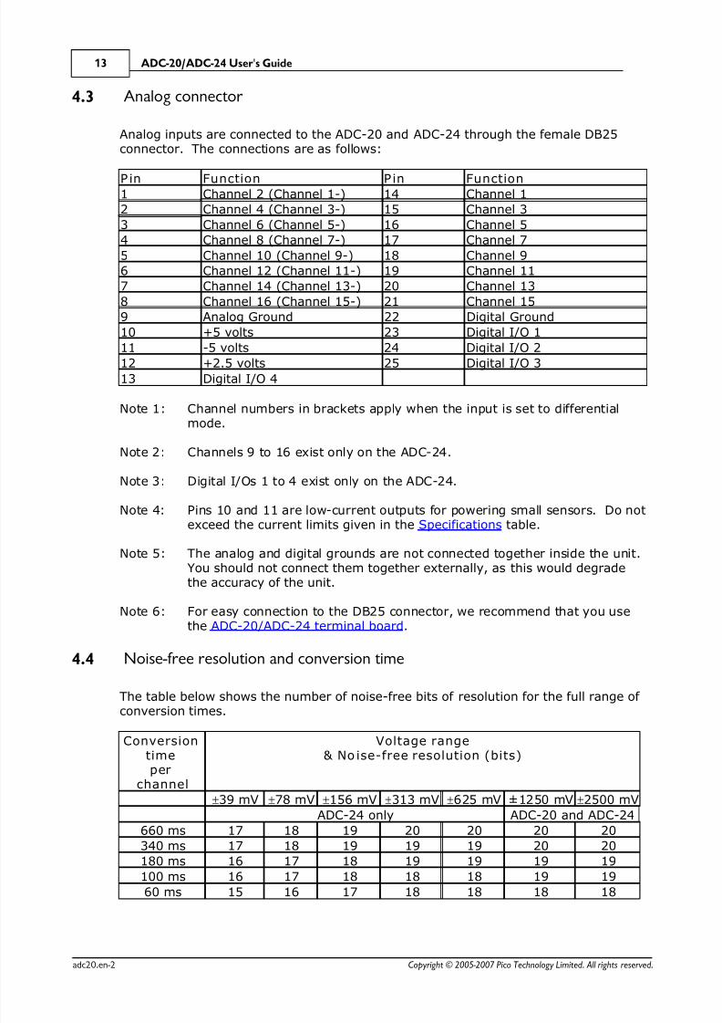
...........................................................................................................................................133 Analog connector
...........................................................................................................................................134 Noise-free resolution and conversion time
...........................................................................................................................................145 ADC-20/ADC-24 terminal board
...........................................................................................................................................146 LED
.....................................................................................................................................155 Programmer's reference
...........................................................................................................................................151 Recording methods
...........................................................................................................................................152 Windows driver
...........................................................................................................................................153 Scaling
...........................................................................................................................................164 Driver functions
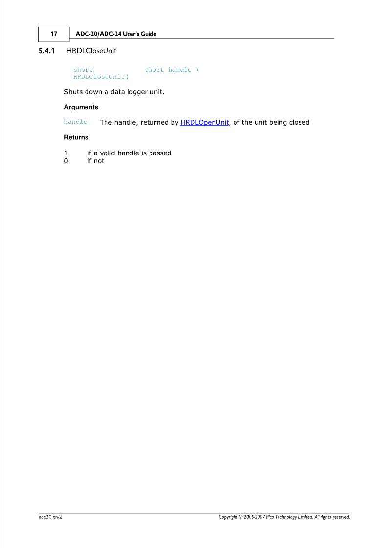
...........................................................................................................................................161 HRDLCloseUnit
...........................................................................................................................................162 HRDLCollectSingleValueAsync
...........................................................................................................................................163 HRDLGetMinMaxAdcCounts
...........................................................................................................................................164 HRDLGetNumberOfEnabledChannels
...........................................................................................................................................165 HRDLGetSingleValue
...........................................................................................................................................166 HRDLGetSingleValueAsync
...........................................................................................................................................167 HRDLGetTimesAndValues
...........................................................................................................................................168 HRDLGetUnitInfo
...........................................................................................................................................169 HRDLGetValues
...........................................................................................................................................1610 HRDLOpenUnit
...........................................................................................................................................1611 HRDLOpenUnitAsync
...........................................................................................................................................1612 HRDLOpenUnitProgress
...........................................................................................................................................1613 HRDLReady
...........................................................................................................................................1614 HRDLRun
...........................................................................................................................................1615 HRDLSetAnalogInChannel

8/6/2019 ADC-24 datalogger
http://slidepdf.com/reader/full/adc-24-datalogger 3/52
IIContents
Copyright © 2005-2007 Pico Technology Limited. All rights reserved. adc20.en-2
...........................................................................................................................................1616 HRDLSetDigitalIOChannel (ADC-24 only)
...........................................................................................................................................1617 HRDLSetInterval
...........................................................................................................................................1618 HRDLSetMains
...........................................................................................................................................1619 HRDLStop
...........................................................................................................................................395 Programming languages
...........................................................................................................................................391 C and C++
...........................................................................................................................................392 Delphi V3
...........................................................................................................................................393 Excel
...........................................................................................................................................394 LabVIEW
...........................................................................................................................................395 Visual Basic
...........................................................................................................................................396 Agilent VEE
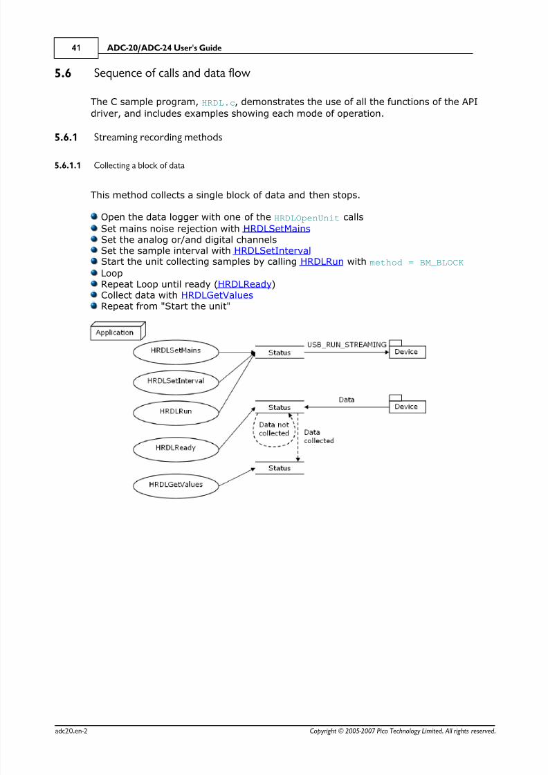
...........................................................................................................................................416 Sequence of calls and data flow
...........................................................................................................................................411 Streaming recording methods
...........................................................................................................................................412 Single-value recording methods
.....................................................................................................................................446 Glossary
..............................................................................................................................................46Index

8/6/2019 ADC-24 datalogger
http://slidepdf.com/reader/full/adc-24-datalogger 4/52
ADC-20/ADC-24 User's Guide1
Copyright © 2005-2007 Pico Technology Limited. All rights reserved.adc20.en-2
1 Introduction
1.1 Overview
The ADC-20 and ADC-24 High-Resolution Data Loggers are multichannel,high-accuracy USB data loggers for use with PCs. They require no external powersupply and take up no expansion slots. They come complete with PicoLog, a programoffering all the features of a stand-alone data logger.
You should have the following items in your ADC-20 or ADC-24 package:
ADC-20 or ADC-24 High-Resolution Data LoggerPico Technology Software and Reference CDInstallation Guide
The CD includes driver software that enables you to write your own programs to
control the data logger, using a variety of popular programming languages.
The hardware and software are compatible with the following operating systems:
Windows XPWindows Vista
and later versions of Windows.
Optional accessories
PP310 ADC-20/ADC-24 Terminal Board

8/6/2019 ADC-24 datalogger
http://slidepdf.com/reader/full/adc-24-datalogger 5/52

8/6/2019 ADC-24 datalogger
http://slidepdf.com/reader/full/adc-24-datalogger 6/52
ADC-20/ADC-24 User's Guide3
Copyright © 2005-2007 Pico Technology Limited. All rights reserved.adc20.en-2
2.2 Legal information
The material contained in this release is licensed, not sold. Pico Technology Limitedgrants a licence to the person who installs this software, subject to the conditionslisted below.
Access
The licensee agrees to allow access to this software only to persons who have beeninformed of these conditions and agree to abide by them.
Usage
The software in this release is for use only with Pico products or with data collectedusing Pico products.
Copyright
Pico Technology Limited claims the copyright of, and retains the rights to, all material(software, documents etc.) contained in this release. You may copy and distribute theentire release in its original state, but must not copy individual items within therelease other than for backup purposes.
Liability
Pico Technology and its agents shall not be liable for any loss, damage or injury,howsoever caused, related to the use of Pico Technology equipment or software,unless excluded by statute.
Fitness for purpose
As no two applications are the same, Pico Technology cannot guarantee that itsequipment or software is suitable for a given application. It is your responsibility,therefore, to ensure that the product is suitable for your application.
Mission-critical applicationsThis software is intended for use on a computer that may be running other softwareproducts. For this reason, one of the conditions of the licence is that it excludes usagein mission-critical applications, such as life-support systems.
Viruses
This software was continuously monitored for viruses during production, but you areresponsible for virus-checking the software once it is installed.

8/6/2019 ADC-24 datalogger
http://slidepdf.com/reader/full/adc-24-datalogger 7/52
Notices 4
Copyright © 2005-2007 Pico Technology Limited. All rights reserved. adc20.en-2
2.3 CE notice
The ADC-20 and ADC-24 meet the intent of EMC directive 89/336/EEC and meets theEN61326-1 (1997) Class B Emissions and Immunity
standard.
The ADC-20 and ADC-24 also meet the intent of the Low Voltage Directive and meetthe BS EN 61010-1:2001 IEC 61010-1:2001 (safety requirements for electrical equipment,
control, and laboratory use) standard.
A Declaration of Conformity is available from Pico Technology Ltd.
2.4 FCC notice
This equipment has been tested and found to comply with the limits for a Class Adigital device, pursuant to Part 15 of the FCC Rules. These limits are designed toprovide reasonable protection against harmful interference when the equipment isoperated in a commercial environment. This equipment generates, uses, and can
radiate radio frequency energy and, if not installed and used in accordance with theinstruction manual, may cause harmful interference to radio communications.Operation of this equipment in a residential area is likely to cause harmful interferencein which case the user will be required to correct the interference at his or her ownexpense.
For safety and maintenance information see the safety warning.
A Declaration of Conformity is available from Pico Technology Ltd.
2.5 Trademarks
Pico Technology Limited and PicoLog are trademarks of Pico Technology Limited,registered in the United Kingdom and other countries. Pico Technology acknowledgesthe following product names as trademarks of their respective owners: Windows,Excel, Visual Basic, LabVIEW, Agilent VEE, Delphi.
2.6 Updates
We provide upgrades, free of charge, from our web site. We reserve the right tocharge for updates or replacements sent out on physical media.
2.7 Support and refunds
If you are dissatisfied with the performance of this software, please contact ourtechnical support staff, who will try to fix the problem within a reasonable time. If youare still dissatisfied, please return the product and software to your supplier within 14days of purchase for a full refund.

8/6/2019 ADC-24 datalogger
http://slidepdf.com/reader/full/adc-24-datalogger 8/52
ADC-20/ADC-24 User's Guide5
Copyright © 2005-2007 Pico Technology Limited. All rights reserved.adc20.en-2
2.8 Company details
Address:
Pico Technology Limited
The Mill HouseCambridge StreetSt NeotsCambridgeshirePE19 1QBUnited Kingdom
Phone: +44 (0)1480 396395Fax: +44 (0)1480 396296
Email:
Technical Support: [email protected]: [email protected]
Web site: www.picotech.com
8/6/2019 ADC-24 datalogger
http://slidepdf.com/reader/full/adc-24-datalogger 9/52

8/6/2019 ADC-24 datalogger
http://slidepdf.com/reader/full/adc-24-datalogger 10/52
ADC-20/ADC-24 User's Guide7
Copyright © 2005-2007 Pico Technology Limited. All rights reserved.adc20.en-2
and then display the New Hardw are Found Wizard:
In the "Welcome to the New Hardware Found Wizard" dialog (above), click Next>.Wait while the wizard installs the software.A dialog will appear like the one below:
Click Continue Anyw ay.Continue to wait while the wizard installs the software.When instructed, click Finish to close the wizard.
8/6/2019 ADC-24 datalogger
http://slidepdf.com/reader/full/adc-24-datalogger 11/52
Getting started 8
Copyright © 2005-2007 Pico Technology Limited. All rights reserved. adc20.en-2
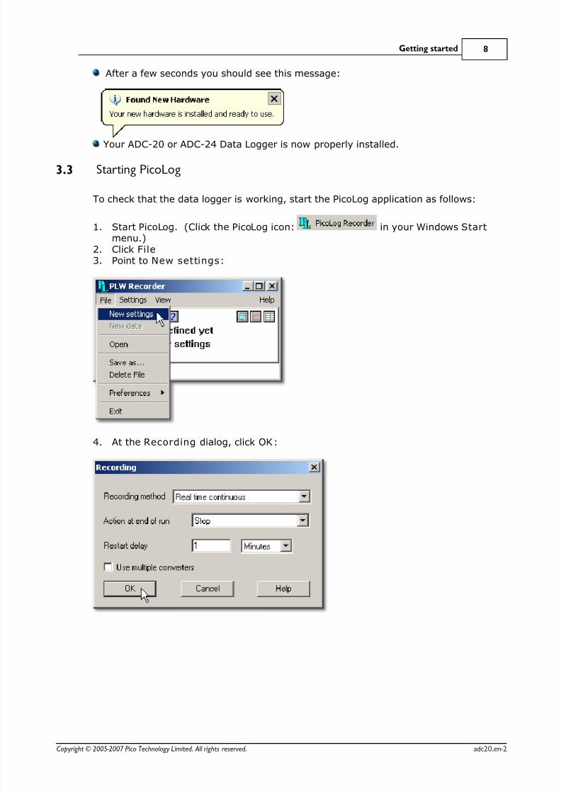
After a few seconds you should see this message:
Your ADC-20 or ADC-24 Data Logger is now properly installed.
3.3 Starting PicoLog
To check that the data logger is working, start the PicoLog application as follows:
1. Start PicoLog. (Click the PicoLog icon: in your Windows Startmenu.)
2. Click File3. Point to New settings:
4. At the Recording dialog, click OK:
8/6/2019 ADC-24 datalogger
http://slidepdf.com/reader/full/adc-24-datalogger 12/52
ADC-20/ADC-24 User's Guide9
Copyright © 2005-2007 Pico Technology Limited. All rights reserved.adc20.en-2
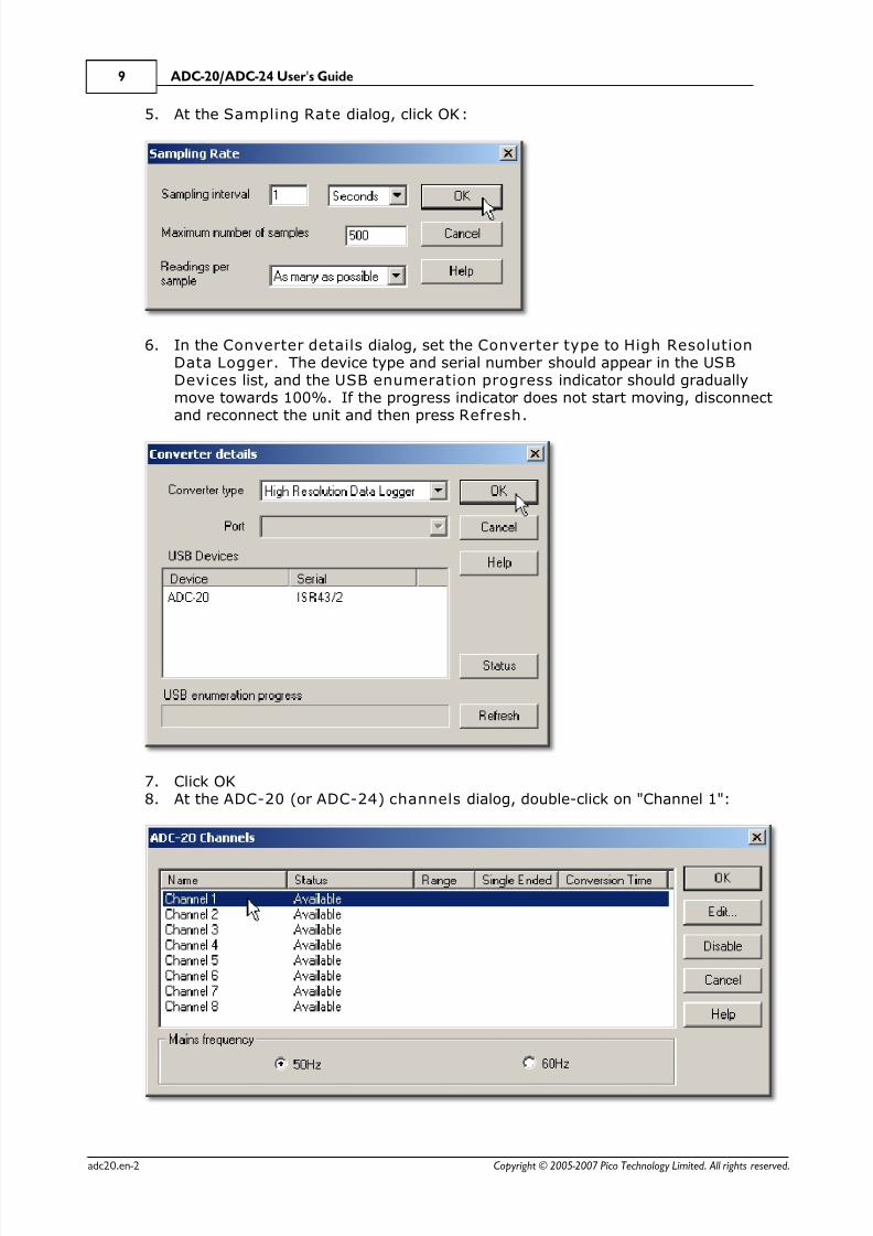
5. At the Sampling Rate dialog, click OK:
6. In the Converter details dialog, set the Converter type to High ResolutionData Logger. The device type and serial number should appear in the USBDevices list, and the USB enumeration progress indicator should graduallymove towards 100%. If the progress indicator does not start moving, disconnectand reconnect the unit and then press Refresh.
7. Click OK8. At the ADC-20 (or ADC-24) channels dialog, double-click on "Channel 1":
8/6/2019 ADC-24 datalogger
http://slidepdf.com/reader/full/adc-24-datalogger 13/52
Getting started 10
Copyright © 2005-2007 Pico Technology Limited. All rights reserved. adc20.en-2
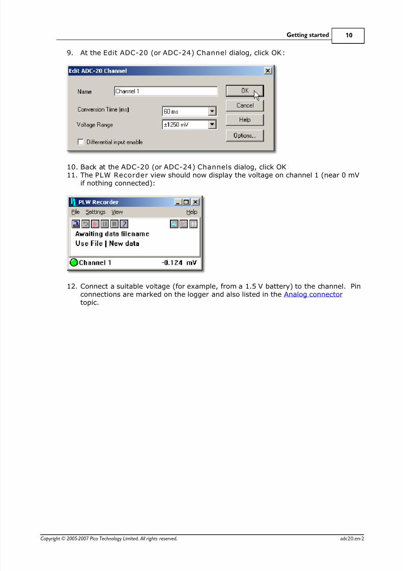
9. At the Edit ADC-20 (or ADC-24) Channel dialog, click OK:
10. Back at the ADC-20 (or ADC-24) Channels dialog, click OK11. The PLW Recorder view should now display the voltage on channel 1 (near 0 mV
if nothing connected):
12. Connect a suitable voltage (for example, from a 1.5 V battery) to the channel. Pinconnections are marked on the logger and also listed in the Analog connector
topic.
8/6/2019 ADC-24 datalogger
http://slidepdf.com/reader/full/adc-24-datalogger 14/52
ADC-20/ADC-24 User's Guide11
Copyright © 2005-2007 Pico Technology Limited. All rights reserved.adc20.en-2
4 About the unit
4.1 Introduction
The ADC-20 and ADC-24 High-Resolution Data Loggers offer the ultimate in preciseand accurate readings. Features such as true differential inputs, galvanic isolation andsoftware-selectable sample rates all contribute to a superior noise-free resolution. TheADC-20 is equipped with a 20-bit A/D converter, and can maintain a gain error of 0.2%. The four true differential inputs may be configured as eight single-ended inputsor any combination in between, such as two differential and four single-ended. TheADC-24 is equipped with a 24-bit A/D converter, and can maintain a gain error of 0.1%. The eight true differential inputs may be configured as 16 single-ended inputsor any combination in between. Power and connection to a PC or laptop is through aUSB 1.1 or USB 2.0 port. Using the supplied PicoLog software, you can record,monitor and analyse collected data, even exporting to third-party applications such asMicrosoft Excel.
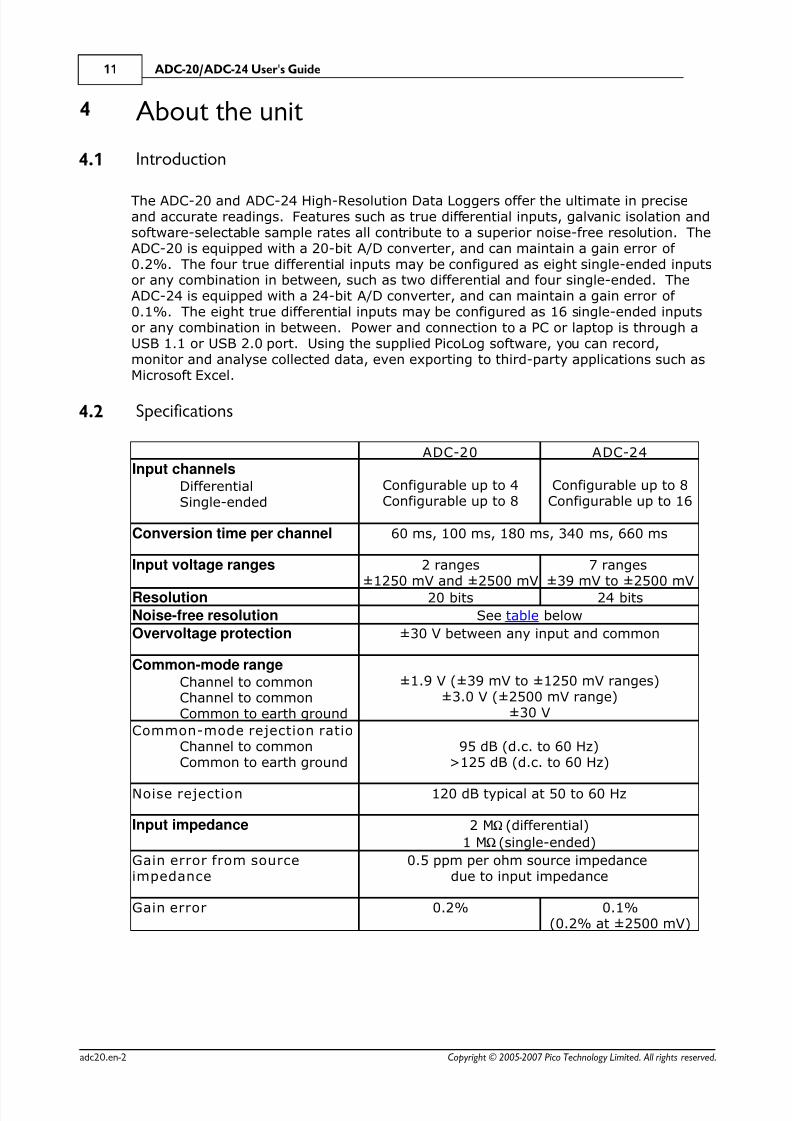
4.2 Specifications
ADC-20 ADC-24
Input channelsDifferentialSingle-ended
Configurable up to 4Configurable up to 8
Configurable up to 8Configurable up to 16
Conversion time per channel 60 ms, 100 ms, 180 ms, 340 ms, 660 ms
Input voltage ranges 2 ranges±1250 mV and ±2500 mV
7 ranges±39 mV to ±2500 mV
Resolution 20 bits 24 bits
Noise-free resolution See table below
Overvoltage protection ±30 V between any input and common
Common-mode rangeChannel to commonChannel to commonCommon to earth ground
±1.9 V (±39 mV to ±1250 mV ranges)±3.0 V (±2500 mV range)
±30 V
Common-mode rejection ratioChannel to commonCommon to earth ground
95 dB (d.c. to 60 Hz)>125 dB (d.c. to 60 Hz)
Noise rejection 120 dB typical at 50 to 60 Hz
Input impedance 2 M W(differential)
1 M W(single-ended)
Gain error from sourceimpedance
0.5 ppm per ohm source impedancedue to input impedance
Gain error 0.2% 0.1%(0.2% at ±2500 mV)
8/6/2019 ADC-24 datalogger
http://slidepdf.com/reader/full/adc-24-datalogger 15/52
About the unit 12
Copyright © 2005-2007 Pico Technology Limited. All rights reserved. adc20.en-2
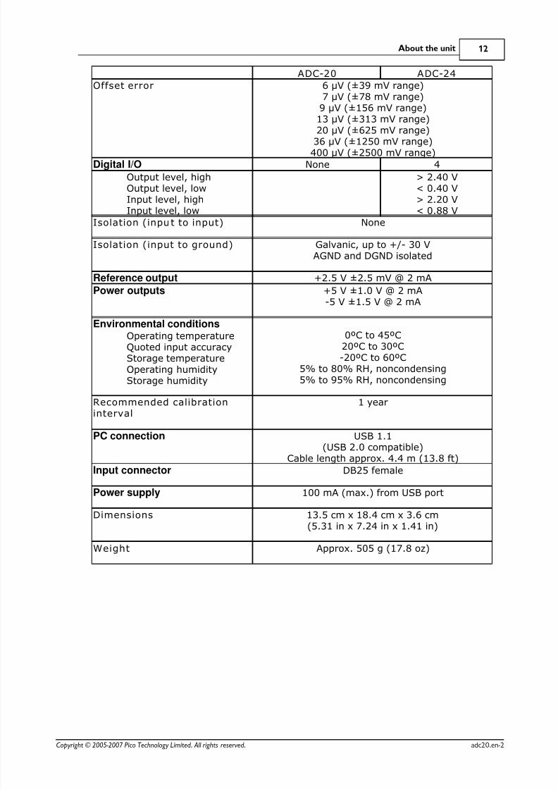
ADC-20 ADC-24
Offset error 6 µV (±39 mV range)7 µV (±78 mV range)9 µV (±156 mV range)13 µV (±313 mV range)20 µV (±625 mV range)
36 µV (±1250 mV range)400 µV (±2500 mV range)
Digital I/O None 4
Output level, highOutput level, lowInput level, highInput level, low
> 2.40 V< 0.40 V> 2.20 V< 0.88 V
Isolation (input to input) None
Isolation (input to ground) Galvanic, up to +/- 30 VAGND and DGND isolated
Reference output +2.5 V ±2.5 mV @ 2 mAPower outputs +5 V ±1.0 V @ 2 mA
-5 V ±1.5 V @ 2 mA
Environmental conditionsOperating temperatureQuoted input accuracyStorage temperatureOperating humidityStorage humidity
0ºC to 45ºC20ºC to 30ºC-20ºC to 60ºC
5% to 80% RH, noncondensing5% to 95% RH, noncondensing
Recommended calibration
interval
1 year
PC connection USB 1.1(USB 2.0 compatible)
Cable length approx. 4.4 m (13.8 ft)
Input connector DB25 female
Power supply 100 mA (max.) from USB port
Dimensions 13.5 cm x 18.4 cm x 3.6 cm(5.31 in x 7.24 in x 1.41 in)
Weight Approx. 505 g (17.8 oz)
8/6/2019 ADC-24 datalogger
http://slidepdf.com/reader/full/adc-24-datalogger 16/52

8/6/2019 ADC-24 datalogger
http://slidepdf.com/reader/full/adc-24-datalogger 17/52
About the unit 14
Copyright © 2005-2007 Pico Technology Limited. All rights reserved. adc20.en-2
4.5 ADC-20/ADC-24 terminal board
For easy connection to the DB25 connector, we recommend that you use theADC-20/ ADC-24 terminal board, part number PP310. This has screw terminals toallow you to connect wires to all of the data logger's inputs and outputs without
soldering. It also has space for voltage-divider resistors, a temperature sensor and aquad op-amp.
4.6 LED
The ADC-20 and ADC-24 have an LED, next to the entry point of the USB cable, thatyou can use to verify that the unit is working. The LED flashes whenever the unit istaking readings. It also flashes briefly during "enumeration", the process that PicoLoguses to detect all Pico USB devices plugged in to the computer.

8/6/2019 ADC-24 datalogger
http://slidepdf.com/reader/full/adc-24-datalogger 18/52
ADC-20/ADC-24 User's Guide15
Copyright © 2005-2007 Pico Technology Limited. All rights reserved.adc20.en-2
5 Programmer's reference
5.1 Recording methods
The ADC-20/ADC-24 driver provides three methods of recording data. All thesemethods support USB1.1.
Streaming – The driver constantly polls the device, and samples are placed in abuffer until retrieved by your application. Precise sample timing is controlled by theunit.
Single Value (blocking) – You make a single request for a sample, blocking thecalling thread, and when the sample has been received the driver returns the value toyour application.
Single Value (non-blocking) – You make a single request for a sample without
blocking the calling thread, and when the sample has been received the driver returnsthe value to your application.
5.2 Windows driver
Once you have installed the software, the Drivers\Win32 subdirectory will contain a
demo program, HRDL.c, that shows exactly how to drive the data logger, and a
driver, PicoHRDL.dll. It also contains a copy of this manual as a PDF file (
ADC20044.PDF).
PicoHRDL.dll is a Windows Dynamic Link Library (DLL), which can be used with C,
C++, Delphi, Visual Basic, National Instruments LabVIEW and Agilent VEE programs.It can also be used with programs like Microsoft Excel, where the macro language is aform of Visual Basic. More than one application can access the Windows DLL at thesame time, as long as the applications do not change the settings for channels thatthey are not using. The driver supports the following operating systems:
Windows XPWindows Vista
and later versions of Windows.
5.3 Scaling
To convert from ADC values to volts, first obtain the minimum and maximum ADCvalues for the selected channel by calling the HRDLGetMinMaxAdcCounts function inthe driver. Next, scale the ADC value to the voltage range you specified when youcalled HRDLSetAnalogInChannel. You can calculate the voltage rangeprogrammatically by using
Vmax = 2500 mV / (2^r)
where r is the range constant you supplied to HRDLSetAnalogInChannel (0 for ±2500mV, 1 for ±1250 mV and so on).
8/6/2019 ADC-24 datalogger
http://slidepdf.com/reader/full/adc-24-datalogger 19/52
Programmer's reference 16
Copyright © 2005-2007 Pico Technology Limited. All rights reserved. adc20.en-2
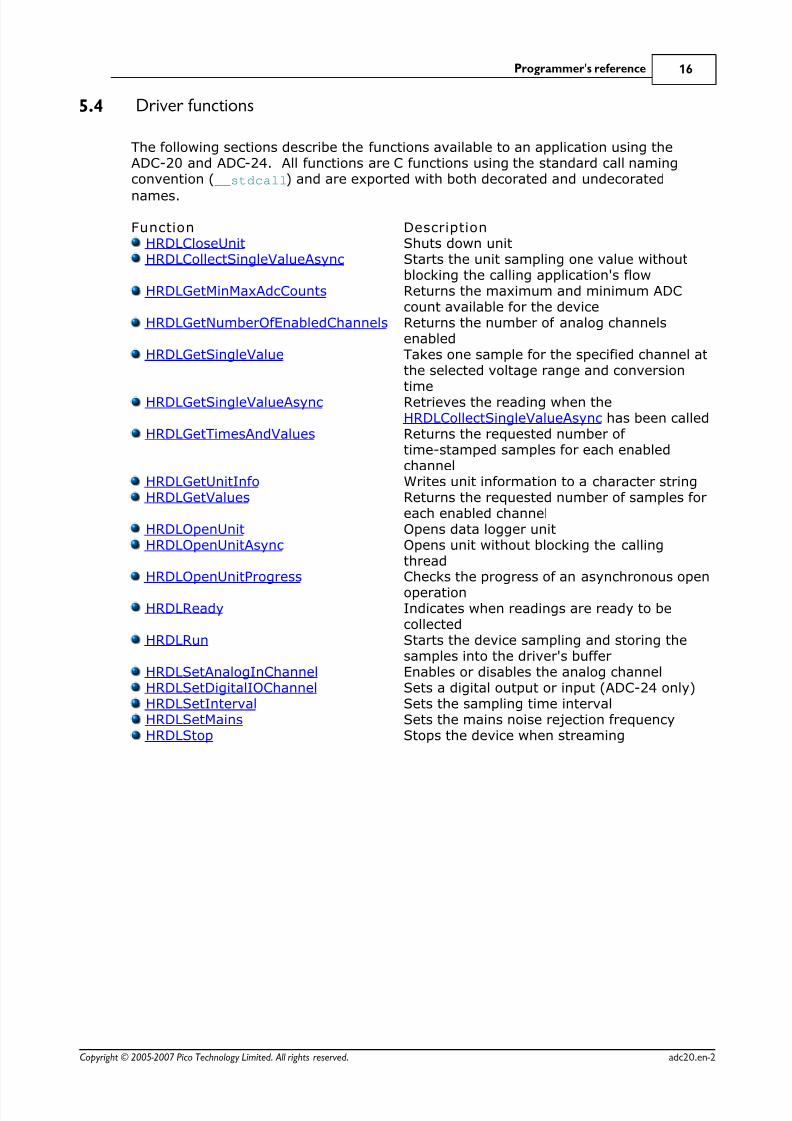
5.4 Driver functions
The following sections describe the functions available to an application using theADC-20 and ADC-24. All functions are C functions using the standard call namingconvention ( __stdcall) and are exported with both decorated and undecorated
names.
Function Description HRDLCloseUnit Shuts down unit HRDLCollectSingleValueAsync Starts the unit sampling one value without
blocking the calling application's flow HRDLGetMinMaxAdcCounts Returns the maximum and minimum ADC
count available for the device HRDLGetNumberOfEnabledChannels Returns the number of analog channels
enabled HRDLGetSingleValue Takes one sample for the specified channel at
the selected voltage range and conversion
time HRDLGetSingleValueAsync Retrieves the reading when theHRDLCollectSingleValueAsync has been called
HRDLGetTimesAndValues Returns the requested number of time-stamped samples for each enabledchannel
HRDLGetUnitInfo Writes unit information to a character string HRDLGetValues Returns the requested number of samples for
each enabled channel HRDLOpenUnit Opens data logger unit HRDLOpenUnitAsync Opens unit without blocking the calling
thread HRDLOpenUnitProgress Checks the progress of an asynchronous open
operation HRDLReady Indicates when readings are ready to be
collected HRDLRun Starts the device sampling and storing the
samples into the driver's buffer HRDLSetAnalogInChannel Enables or disables the analog channel HRDLSetDigitalIOChannel Sets a digital output or input (ADC-24 only) HRDLSetInterval Sets the sampling time interval HRDLSetMains Sets the mains noise rejection frequency HRDLStop Stops the device when streaming
8/6/2019 ADC-24 datalogger
http://slidepdf.com/reader/full/adc-24-datalogger 20/52

8/6/2019 ADC-24 datalogger
http://slidepdf.com/reader/full/adc-24-datalogger 21/52
Programmer's reference 18
Copyright © 2005-2007 Pico Technology Limited. All rights reserved. adc20.en-2
5.4.2 HRDLCollectSingleValueAsync
shortHRDLCollectSingleValueAsync(
short handle,short channel,short range,short conversionTime,
short singleEnded )
This function starts the unit sampling one value without blocking the callingapplication's flow. Used in conjunction with HRDLGetSingleValueAsync andHRDLReady.
Arguments
handle Handle returned by HRDLOpenUnitchannel Channel number to convert. If the channel is not valid then the
function will fail.range The voltage range to be used. If the range is not valid, the
function HRDLGetSingleValueAsync will return 0.conversionTime The time interval in which the sample should be converted. If the conversion time is invalid,the functionHRDLGetSingleValueAsync will fail and return 0.
singleEnded The type of voltage to be measured:0: differentialnonzero: single-ended
Returns
1 if a valid handle is passed and the settings are correct0 if not
8/6/2019 ADC-24 datalogger
http://slidepdf.com/reader/full/adc-24-datalogger 22/52
ADC-20/ADC-24 User's Guide19
Copyright © 2005-2007 Pico Technology Limited. All rights reserved.adc20.en-2
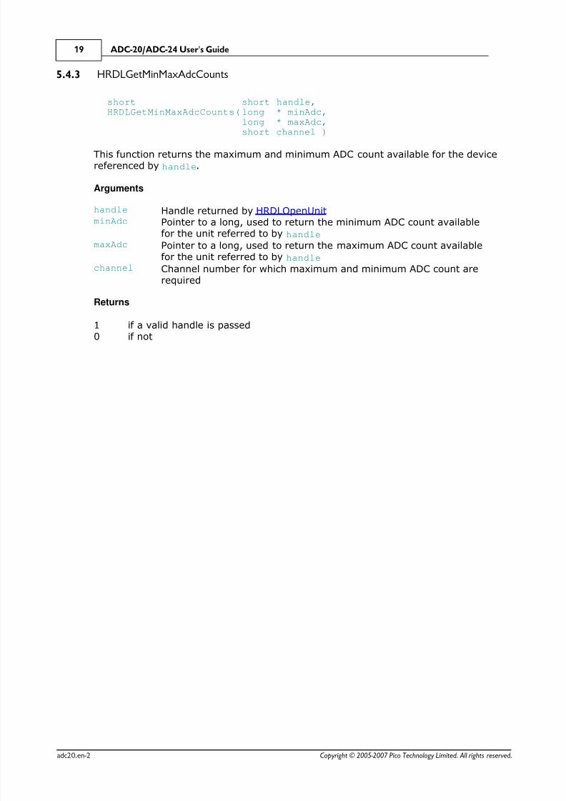
5.4.3 HRDLGetMinMaxAdcCounts
shortHRDLGetMinMaxAdcCounts(
short handle,long * minAdc,long * maxAdc,short channel )
This function returns the maximum and minimum ADC count available for the devicereferenced by handle.
Arguments
handle Handle returned by HRDLOpenUnitminAdc Pointer to a long, used to return the minimum ADC count available
for the unit referred to by handlemaxAdc Pointer to a long, used to return the maximum ADC count available
for the unit referred to by handlechannel Channel number for which maximum and minimum ADC count are
required
Returns
1 if a valid handle is passed0 if not
8/6/2019 ADC-24 datalogger
http://slidepdf.com/reader/full/adc-24-datalogger 23/52
Programmer's reference 20
Copyright © 2005-2007 Pico Technology Limited. All rights reserved. adc20.en-2
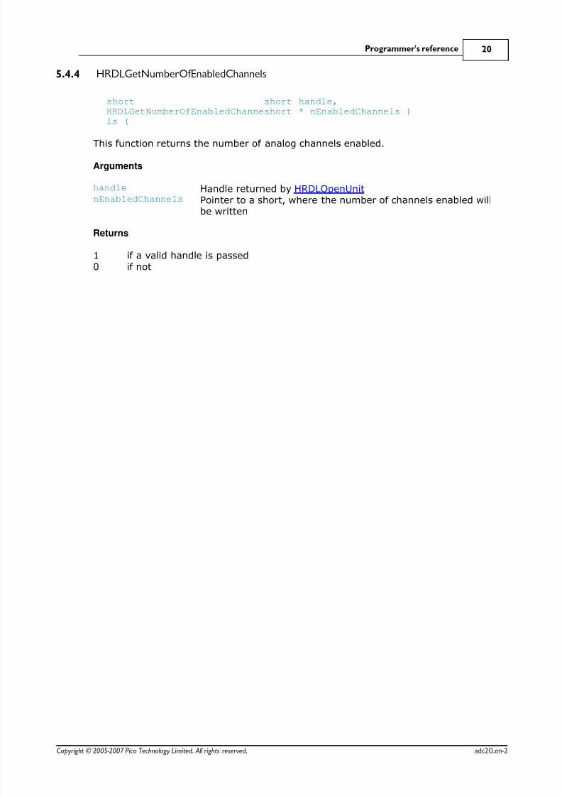
5.4.4 HRDLGetNumberOfEnabledChannels
shortHRDLGetNumberOfEnabledChannels (
short handle,short * nEnabledChannels )
This function returns the number of analog channels enabled.
Arguments
handle Handle returned by HRDLOpenUnitnEnabledChannels Pointer to a short, where the number of channels enabled will
be written
Returns
1 if a valid handle is passed0 if not

8/6/2019 ADC-24 datalogger
http://slidepdf.com/reader/full/adc-24-datalogger 24/52

8/6/2019 ADC-24 datalogger
http://slidepdf.com/reader/full/adc-24-datalogger 25/52
8/6/2019 ADC-24 datalogger
http://slidepdf.com/reader/full/adc-24-datalogger 26/52
ADC-20/ADC-24 User's Guide23
Copyright © 2005-2007 Pico Technology Limited. All rights reserved.adc20.en-2
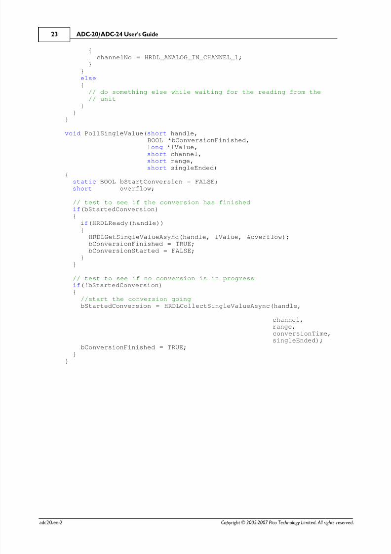
{channelNo = HRDL_ANALOG_IN_CHANNEL_1;
}}else{
// do something else while waiting for the reading from the
// unit}
}}
void PollSingleValue(short handle,BOOL *bConversionFinished,
long *lValue, short channel, short range, short singleEnded){
static BOOL bStartConversion = FALSE;short overflow;
// test to see if the conversion has finished if(bStartedConversion)
{if(HRDLReady(handle)){
HRDLGetSingleValueAsync(handle, lValue, &overflow);bConversionFinished = TRUE;bConversionStarted = FALSE;
}}
// test to see if no conversion is in progressif(!bStartedConversion)
{//start the conversion goingbStartedConversion = HRDLCollectSingleValueAsync(handle,
channel,range,conversionTime,singleEnded);
bConversionFinished = TRUE;}
}

8/6/2019 ADC-24 datalogger
http://slidepdf.com/reader/full/adc-24-datalogger 27/52
Programmer's reference 24
Copyright © 2005-2007 Pico Technology Limited. All rights reserved. adc20.en-2
5.4.7 HRDLGetTimesAndValues
longHRDLGetTimesAndValues (
short handle,long * times,long * values,short * overflow,
long noOfValues )
This function returns the requested number of samples for each enabled channel andthe times when the samples were taken, so the values array needs to be (number of
values) x (number of enabled channels). When one or more of the digital IOs areenabled as inputs, they count as one additional channel. The function informs the userif the voltages for any of the enabled channels have overflowed.
Arguments
handle Handle returned by HRDLOpenUnit.times Pointer to a long where times will be written.values
Pointer to a long where sample values will be written. If more thanone channel is active, the samples are interleaved. If digital channelsare enabled then they are always the first values. See table belowfor the order in which data are returned.
overflow Pointer to a short indicating any inputs that have exceeded theirmaximum voltage range. Channels with overvoltages are indicatedby a high bit, with the LSB indicating channel 1 and the MSB channel16.
noOfValues The number of samples to collect for each active channel
Returns
A non-zero number if successful indicating the number of values returned,
0 if the call failed or no values available
Ordering of returned data (example)
When two analog channels (e.g. 1 and 5) are enabled and a digital channel is set asan input, the data are returned in the following order.
Sample No: 0 1 2 3 4 5 6 7 8 9 10 11 12 13 14 . n-3 n-2 n-1Channel: DI 1 5 DI 1 5 DI 1 5 DI 1 5 DI 1 5 . DI 1 5
where n represents the value returned by the function and DI the digital inputs.
The channels are always ordered from channel 1 up to the maximum channel number(ADC-24: channel 16, ADC-20: channel 8). If one or more digital channels are set asinputs then the first sample contains the digital channels.
Digital inputs
The digital channels are represented by a binary bit pattern with 0 representing off,and 1 representing on. Digital input 1 is in bit 0.

8/6/2019 ADC-24 datalogger
http://slidepdf.com/reader/full/adc-24-datalogger 28/52
ADC-20/ADC-24 User's Guide25
Copyright © 2005-2007 Pico Technology Limited. All rights reserved.adc20.en-2
5.4.8 HRDLGetUnitInfo
shortHRDLGetUnitInfo (
short handle,char * string,short stringLength,short info )
This function writes information about the data logger to a character string. If thelogger fails to open, only info = HRDL_ERROR (7) is available to explain why the last
open unit call failed. When retrieving the driver version, the handle value is ignored.
Arguments
handle Handle to the device from which information is required. If an invalidhandle is passed, the error code from the last unit that failed to openis returned (as if info = HRDL_ERROR), unless info =
HRDL_DRIVER_VERSION and then the driver version is returned.string Pointer to the character string buffer in the calling function where
the unit information string (selected with info) will be stored. If anull pointer is passed, no information will be written.
stringLength Length of the character string buffer. If the string is not long enoughto accept all of the information, only the first stringLengthcharacters are returned.
info Enumerated type (listed below) specifying what information isrequired from the driver.
Returns
The length of the string written to the character string buffer, string, by the
function.
If one of the parameters is out of range, or a null pointer is passed for string, thefunction will return zero.
Values of info
info Description ExampleHRDL_DRIVER_VERSION (0) The version of PicoHRDL.dll 1.0.0.1HRDL_USB_VERSION (1) The type of USB to which the unit is
connected1.1
HRDL_HARDWARE_VERSION (2) The hardware version of the HRDLattached
1
HRDL_VARIANT_INFO (3) Information about the type of HRDL
attached
24
HRDL_BATCH_AND_SERIAL (4) Batch and serial numbers of the unit CMY02/116HRDL_CAL_DATE (5) Calibration date of the unit 09Sep05HRDL_KERNEL_DRIVER_VERSION (6) Kernel driver versionHRDL_ERROR (7) One of the error codes listed in Error
codes below4
HRDL_SETTINGS_ERROR (8) One of the error codes listed inSetting Error Codes below

8/6/2019 ADC-24 datalogger
http://slidepdf.com/reader/full/adc-24-datalogger 29/52
Programmer's reference 26
Copyright © 2005-2007 Pico Technology Limited. All rights reserved. adc20.en-2
Error codes (when info = HRDL_ERROR)
Error code DescriptionHRDL_OK (0) The unit is functioning correctlyHRDL_KERNEL_DRIVER (1) The picopp.sys file is to old to support this
productHRDL_NOT_FOUND (2) No data logger could be foundHRDL_CONFIG_FAIL (3) Unable to download firmwareHRDL_ERROR_OS_NOT_SUPPORTED (4) The operating system is not supported by this
deviceHRDL_MAX_DEVICES (5) The maximum number of units allowed are
already open
Settings Error Codes (when info = HRDL_SETTINGS_ERROR)
Settings Error Code DescriptionSE_CONVERSION_TIME_OUT_OF_RANGE(0)
The conversion time parameter is out of range
SE_SAMPLEINTERVAL_OUT_OF_RANGE(1)
The sample time interval is out of range
SE_CONVERSION_TIME_TOO_SLOW (2) The conversion time chosen is not fast enoughto convert all channels within the sampleinterval
SE_CHANNEL_NOT_AVAILABLE (3) The channel being set is valid but notcurrently available
SE_INVALID_CHANNEL (4) The channel being set is not valid for thisdevice
SE_INVALID_VOLTAGE_RANGE (5) The voltage range being set for this device isnot valid
SE_INVALID_PARAMETER (6) One or more parameters are invalid
SE_CONVERSION_IN_PROGRESS (7) A conversion is in progress for a singleasynchronous operation
SE_OK (8) All settings have been completed successfully

8/6/2019 ADC-24 datalogger
http://slidepdf.com/reader/full/adc-24-datalogger 30/52
ADC-20/ADC-24 User's Guide27
Copyright © 2005-2007 Pico Technology Limited. All rights reserved.adc20.en-2
5.4.9 HRDLGetValues
long HRDLGetValues(
short handle,long * values,short * overflow,long noOfValues )
This function returns the requested number of samples for each enabled channel, sothe size of the values array needs to be (number of values) x (number of enabled
channels). When one or more of the digital IOs are enabled as inputs, they count asone additional channel. The function informs the user if the voltages of any of theenabled channels have overflowed.
Arguments
handle Returned by HRDLOpenUnit.values Pointer to a long where the sample values are written. If more than
one channel is active, the samples are interleaved. If digital channels
are enabled then they are always the first value. See table below forthe order in which data are returned.
overflow Pointer to a short indicating any inputs that have exceeded theirmaximum voltage range. Channels with overvoltages are indicatedby a high bit, with the LSB indicating channel 1 and the MSB channel16.
noOfValues The number of samples to collect for each active channel
Returns
A non-zero number if successful indicating the number of values returned, or0 if the call failed or no values available
Ordering of returned data (example)
When two analog channels (e.g. 1 and 5) are enabled and a digital channel is set asan input, the data are returned in the following order.
Sample No: 0 1 2 3 4 5 6 7 8 9 10 11 12 13 14 . n-3 n-2 n-1Channel: DI 1 5 DI 1 5 DI 1 5 DI 1 5 DI 1 5 . DI 1 5
where n represents the value returned by the function and DI the digital inputs.
The channels are always ordered from channel 1 up to the maximum channel number(ADC-24: channel 16, ADC-20: channel 8). If one or more digital channels are set as
inputs then the first sample contains the digital channels.
Digital inputs
The digital channels are represented by a binary bit pattern with 0 representing off,and 1 representing on. Digital input 1 is in bit 0.

8/6/2019 ADC-24 datalogger
http://slidepdf.com/reader/full/adc-24-datalogger 31/52
Programmer's reference 28
Copyright © 2005-2007 Pico Technology Limited. All rights reserved. adc20.en-2
5.4.10 HRDLOpenUnit
short HRDLOpenUnit(
void )
This function opens a data logger. The API driver can support up to four units.
Arguments
None
Returns
-1 if the unit fails to open0 if no unit is found>= 1 handle to the device opened
8/6/2019 ADC-24 datalogger
http://slidepdf.com/reader/full/adc-24-datalogger 32/52
ADC-20/ADC-24 User's Guide29
Copyright © 2005-2007 Pico Technology Limited. All rights reserved.adc20.en-2
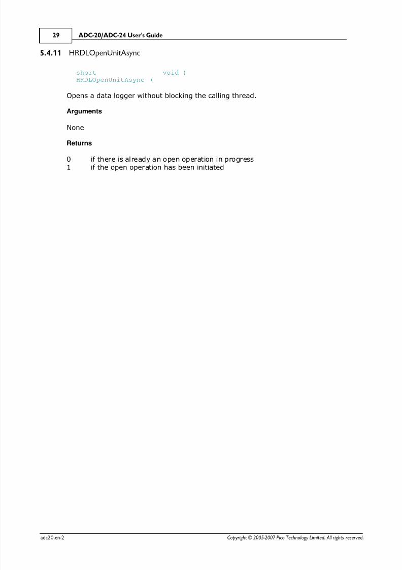
5.4.11 HRDLOpenUnitAsync
shortHRDLOpenUnitAsync (
void )
Opens a data logger without blocking the calling thread.
Arguments
None
Returns
0 if there is already an open operation in progress1 if the open operation has been initiated
8/6/2019 ADC-24 datalogger
http://slidepdf.com/reader/full/adc-24-datalogger 33/52
Programmer's reference 30
Copyright © 2005-2007 Pico Technology Limited. All rights reserved. adc20.en-2
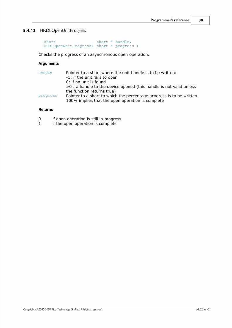
5.4.12 HRDLOpenUnitProgress
shortHRDLOpenUnitProgress(
short * handle,short * progress )
Checks the progress of an asynchronous open operation.
Arguments
handle Pointer to a short where the unit handle is to be written:-1: if the unit fails to open0: if no unit is found>0 : a handle to the device opened (this handle is not valid unlessthe function returns true)
progress Pointer to a short to which the percentage progress is to be written.100% implies that the open operation is complete
Returns
0 if open operation is still in progress1 if the open operation is complete

8/6/2019 ADC-24 datalogger
http://slidepdf.com/reader/full/adc-24-datalogger 34/52

8/6/2019 ADC-24 datalogger
http://slidepdf.com/reader/full/adc-24-datalogger 35/52
Programmer's reference 32
Copyright © 2005-2007 Pico Technology Limited. All rights reserved. adc20.en-2
5.4.14 HRDLRun
short HRDLRun( short handle,long nValues,short method )
This function starts the device sampling and storing the samples in the driver's buffer.See Streaming recording methods for help on using this function.
Arguments
handle Handle returned by HRDLOpenUnit.nValues Number of samples to collect for each active channel.method Sampling method. This should be one of the values listed below.
Returns
0 if failed,
1 if successful
Sampling methods
method DescriptionBM_BLOCK (0) Collect a single block and stopBM_WINDOW (1) Collect a sequence of overlapping blocksBM_STREAM (2) Collect a continuous stream of data

8/6/2019 ADC-24 datalogger
http://slidepdf.com/reader/full/adc-24-datalogger 36/52
ADC-20/ADC-24 User's Guide33
Copyright © 2005-2007 Pico Technology Limited. All rights reserved.adc20.en-2
5.4.15 HRDLSetAnalogInChannel
shortHRDLSetAnalogInChannel(
short handle,short channel,short enabled,short range,
short singleEnded )
This function enables or disables the selected analog channel. If you wish to enablean odd-numbered channel in differential mode, you must first make sure that itscorresponding even-numbered channel is disabled. (For example, to set channel 1 todifferential mode, first ensure that channel 2 is disabled.)
Arguments
handle Handle returned by HRDLOpenUnit.channel The channel that will be enabled or disabled.
ADC-20: 1 to 8
ADC-24: 1 to 16enabled Sets the channel active or dormant.0: dormant<> 0: active
range The voltage range to be used during sampling. Applies only toselected channel. See Voltage ranges below.
singleEnded Non-zero to measure a single-ended voltage.Zero for a differential voltage.
Returns
0 if failed1 if successful
If the function fails, call HRDLGetUnitInfo with info = HRDL_SETTINGS_ERROR (8) to
obtain the specific settings error.
Voltage ranges
range Voltage range Availabil ityHRDL_2500_MV (0) ±2500 mV ADC-20 and ADC-24HRDL_1250_MV (1) ±1250 mV ADC-20 and ADC-24HRDL_625_MV (2) ±625 mV ADC-24 onlyHRDL_313_MV (3) ±312.5 mV ADC-24 onlyHRDL_156_MV (4) ±156.25 mV ADC-24 onlyHRDL_78_MV (5) ±78.125 mV ADC-24 onlyHRDL_39_MV (6) ±39.0625 mV ADC-24 only
8/6/2019 ADC-24 datalogger
http://slidepdf.com/reader/full/adc-24-datalogger 37/52
Programmer's reference 34
Copyright © 2005-2007 Pico Technology Limited. All rights reserved. adc20.en-2
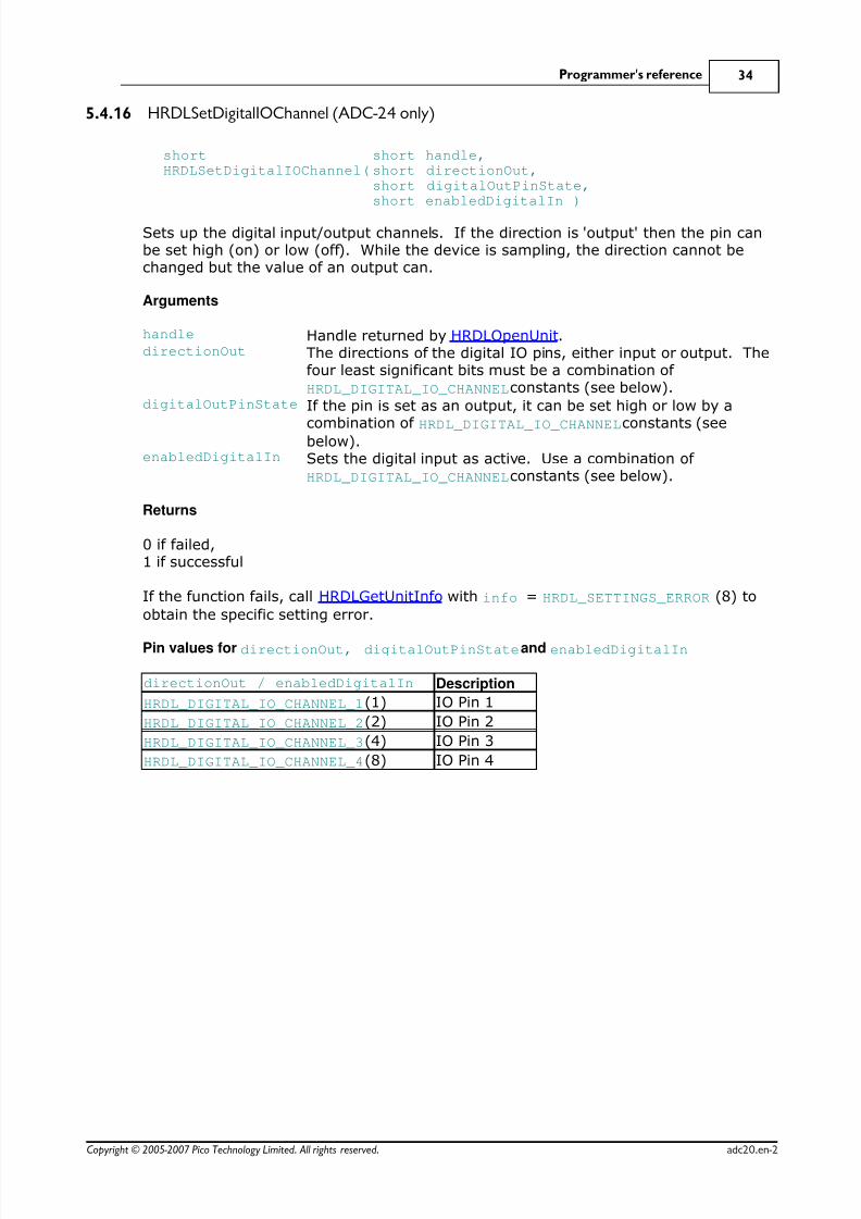
5.4.16 HRDLSetDigitalIOChannel (ADC-24 only)
shortHRDLSetDigitalIOChannel(
short handle,short directionOut,short digitalOutPinState,short enabledDigitalIn )
Sets up the digital input/output channels. If the direction is 'output' then the pin canbe set high (on) or low (off). While the device is sampling, the direction cannot bechanged but the value of an output can.
Arguments
handle Handle returned by HRDLOpenUnit.directionOut The directions of the digital IO pins, either input or output. The
four least significant bits must be a combination of
HRDL_DIGITAL_IO_CHANNEL constants (see below).digitalOutPinState If the pin is set as an output, it can be set high or low by a
combination of HRDL_DIGITAL_IO_CHANNEL constants (seebelow).
enabledDigitalIn Sets the digital input as active. Use a combination of
HRDL_DIGITAL_IO_CHANNEL constants (see below).
Returns
0 if failed,1 if successful
If the function fails, call HRDLGetUnitInfo with info = HRDL_SETTINGS_ERROR (8) to
obtain the specific setting error.
Pin values for directionOut, digitalOutPinState and enabledDigitalIn
directionOut / enabledDigitalIn Description
HRDL_DIGITAL_IO_CHANNEL_1 (1) IO Pin 1
HRDL_DIGITAL_IO_CHANNEL_2 (2) IO Pin 2
HRDL_DIGITAL_IO_CHANNEL_3 (4) IO Pin 3
HRDL_DIGITAL_IO_CHANNEL_4 (8) IO Pin 4

8/6/2019 ADC-24 datalogger
http://slidepdf.com/reader/full/adc-24-datalogger 38/52
ADC-20/ADC-24 User's Guide35
Copyright © 2005-2007 Pico Technology Limited. All rights reserved.adc20.en-2
Examples:
To set digital channels 1 and 2 to input and digital channels 3 and 4 to output:
directionOut =
HRDL_DIGITAL_IO_CHANNEL_4 (8) + HRDL_DIGITAL_IO_CHANNEL_3 (4) = 12
To set digital channel 4 high and digital channel 3 low:
digitalOutPinState = HRDL_DIGITAL_IO_CHANNEL_4 (8) = 8To set only digital channel 3 high:
digitalOutPinState = HRDL_DIGITAL_IO_CHANNEL_3 (4) = 4
To turn both digital channels 3 and 4 on:
digitalOutPinState =
HRDL_DIGITAL_IO_CHANNEL_4 (8) + HRDL_DIGITAL_IO_CHANNEL_3 (4) = 12
Example bit patterns for directionOut parameter:
Decimal BitPattern
DigitalChannel 4
DigitalChannel 3
DigitalChannel 2
DigitalChannel 1
1 0001 Input Input Input Output
10 1010 Output Input Output Input12 1100 Output Output Input Input
13 1101 Output Output Input Output
The above is a selection of the 16 different options available for the directionOut
parameter. When a digital channel has been selected as an output, it can then be seton or off with the digitalOutputPinState parameter, again using binary bit patterns
to represent the different digital channels.
The default setting for the digital channels is "output, off".

8/6/2019 ADC-24 datalogger
http://slidepdf.com/reader/full/adc-24-datalogger 39/52
Programmer's reference 36
Copyright © 2005-2007 Pico Technology Limited. All rights reserved. adc20.en-2
5.4.17 HRDLSetInterval
shortHRDLSetInterval(
short handle,long sampleInterval_ms,short conversionTime )
This sets the sampling time interval. The number of channels active must be able toconvert within the specified interval. Arguments
handle Handle returned by HRDLOpenUnit.sampleInterval_ms Time interval in milliseconds within which all conversions must
take place before the next set of conversions starts.conversionTime The amount of time given to one channel's conversion. This
must be one of the constants below.
Returns
0 if failed1 if successful
If the function fails, call HRDLGetUnitInfo with info = HRDL_SETTINGS_ERRORS for the
specific settings error.
Conversion times
conversionTime Conversion timeHRDL_60MS (0) 60 msHRDL_100MS (1) 100 msHRDL_180MS (2)
180 msHRDL_340MS (3) 340 msHRDL_660MS (4) 660 ms

8/6/2019 ADC-24 datalogger
http://slidepdf.com/reader/full/adc-24-datalogger 40/52
ADC-20/ADC-24 User's Guide37
Copyright © 2005-2007 Pico Technology Limited. All rights reserved.adc20.en-2
5.4.18 HRDLSetMains
shortHRDLSetMains(
short handle,short sixtyHertz )
This function configures the mains noise rejection setting. Rejection takes effect thenext time sampling occurs.
Arguments
handle Handle returned by HRDLOpenUnit.sixtyHertz Specifies whether 50 Hz or 60 Hz noise rejection is applied.
0: reject 50Hz<> 0: reject 60 Hz
Returns
0 if failed
1 if successful

8/6/2019 ADC-24 datalogger
http://slidepdf.com/reader/full/adc-24-datalogger 41/52
Programmer's reference 38
Copyright © 2005-2007 Pico Technology Limited. All rights reserved. adc20.en-2
5.4.19 HRDLStop
void HRDLStop (short handle )
This function stops the device when streaming.
Arguments
handle Handle returned by HRDLOpenUnit.
8/6/2019 ADC-24 datalogger
http://slidepdf.com/reader/full/adc-24-datalogger 42/52
ADC-20/ADC-24 User's Guide39
Copyright © 2005-2007 Pico Technology Limited. All rights reserved.adc20.en-2
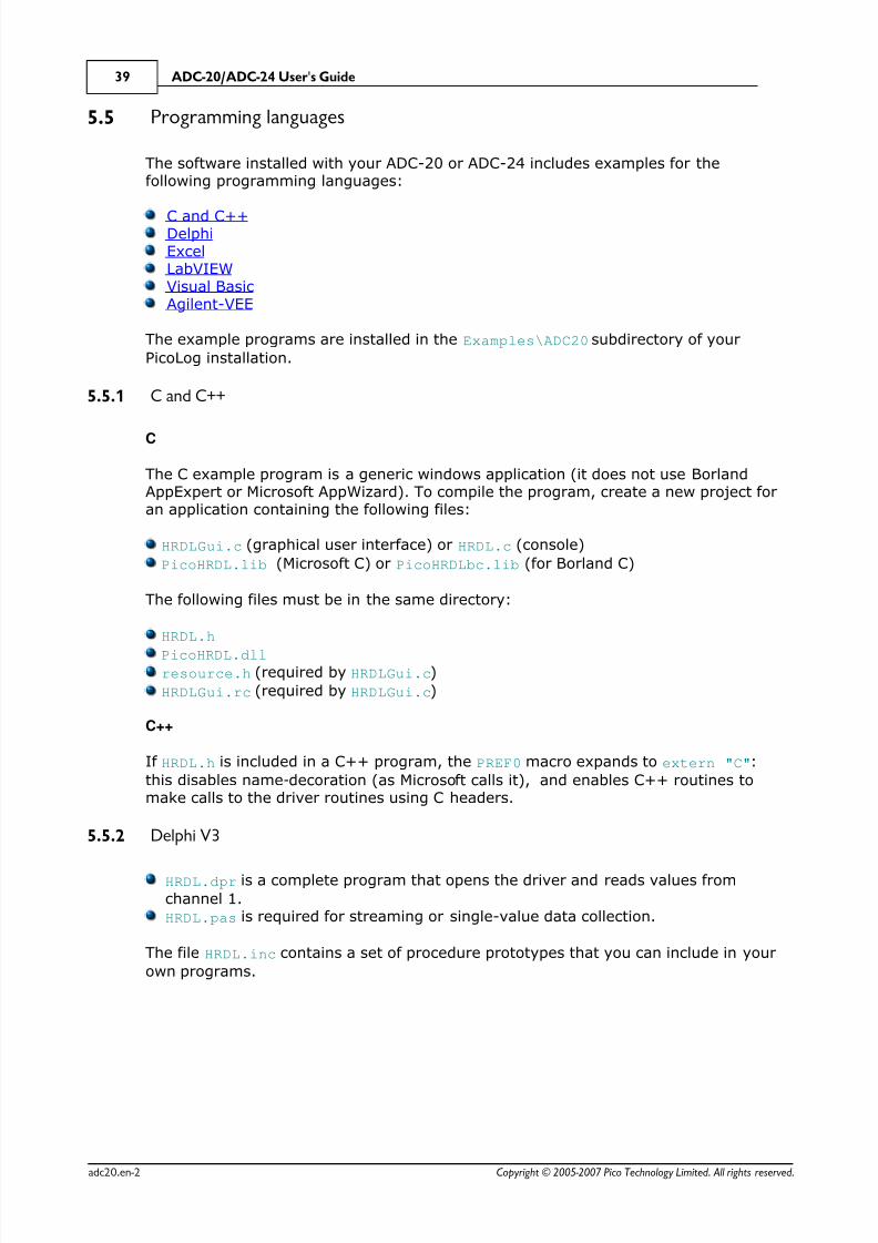
5.5 Programming languages
The software installed with your ADC-20 or ADC-24 includes examples for thefollowing programming languages:
C and C++ Delphi Excel LabVIEW Visual Basic Agilent-VEE
The example programs are installed in the Examples\ADC20 subdirectory of your
PicoLog installation.
5.5.1 C and C++
C
The C example program is a generic windows application (it does not use BorlandAppExpert or Microsoft AppWizard). To compile the program, create a new project foran application containing the following files:
HRDLGui.c (graphical user interface) or HRDL.c (console)
PicoHRDL.lib (Microsoft C) or PicoHRDLbc.lib (for Borland C)
The following files must be in the same directory:
HRDL.h
PicoHRDL.dll resource.h (required by HRDLGui.c)
HRDLGui.rc (required by HRDLGui.c)
C++
If HRDL.h is included in a C++ program, the PREF0 macro expands to extern "C":
this disables name-decoration (as Microsoft calls it), and enables C++ routines tomake calls to the driver routines using C headers.
5.5.2 Delphi V3
HRDL.dpr is a complete program that opens the driver and reads values from
channel 1.
HRDL.pas is required for streaming or single-value data collection.
The file HRDL.inc contains a set of procedure prototypes that you can include in your
own programs.
8/6/2019 ADC-24 datalogger
http://slidepdf.com/reader/full/adc-24-datalogger 43/52
8/6/2019 ADC-24 datalogger
http://slidepdf.com/reader/full/adc-24-datalogger 44/52

8/6/2019 ADC-24 datalogger
http://slidepdf.com/reader/full/adc-24-datalogger 45/52
Programmer's reference 42
Copyright © 2005-2007 Pico Technology Limited. All rights reserved. adc20.en-2
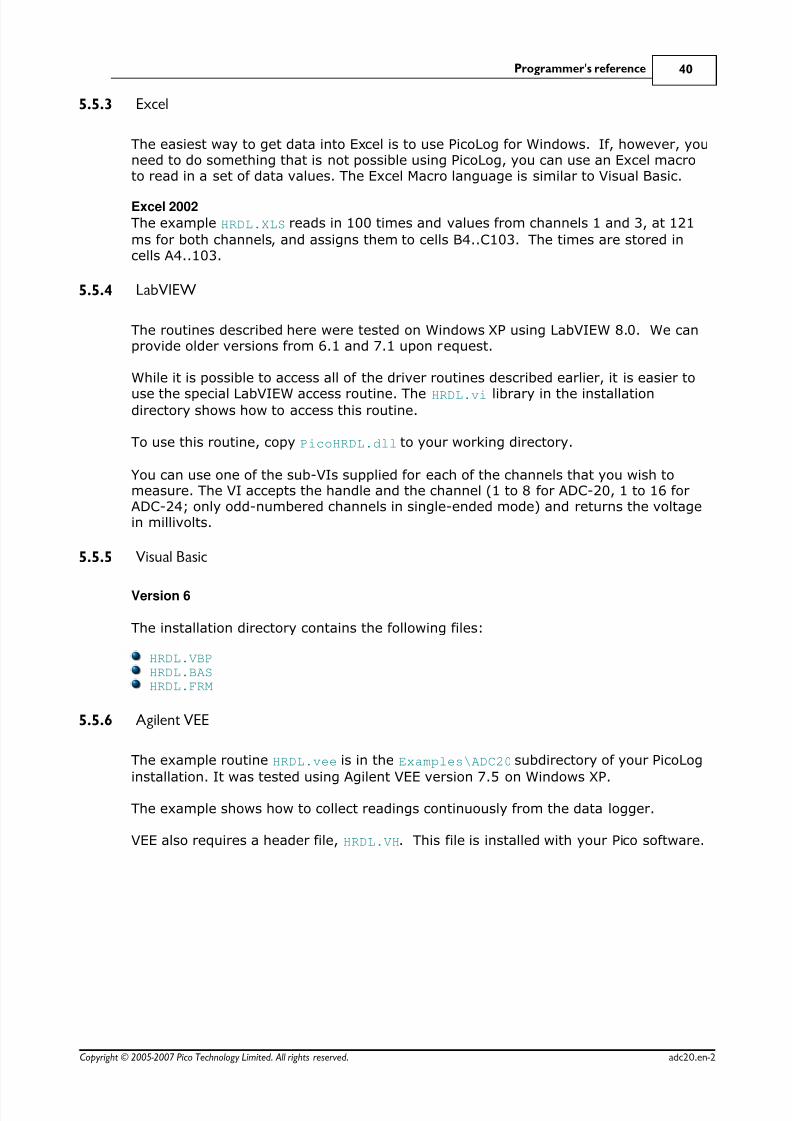
5.6.1.2 Collecting windowed or streaming data
This method causes the device to start sampling. Samples are stored in the driver'sbuffer. In windowed mode, the buffer will always contain the requested number of samples, but generally only a subset of these are new data. In streaming mode, new
data are returned continuously.
Open the data logger with one of the HRDLOpenUnit calls
Set mains noise rejection with HRDLSetMainsSet the analog or/and digital channelsSet the sample interval with HRDLSetIntervalStart the unit collecting samples by calling HRDLRun with method = BM_WINDOW orBM_STREAM
LoopRepeat Loop until ready (HRDLReady)Collect data whenever you want with HRDLGetValues

8/6/2019 ADC-24 datalogger
http://slidepdf.com/reader/full/adc-24-datalogger 46/52
8/6/2019 ADC-24 datalogger
http://slidepdf.com/reader/full/adc-24-datalogger 47/52
Glossary 44
Copyright © 2005-2007 Pico Technology Limited. All rights reserved. adc20.en-2
6 Glossary
Asynchronous
In asynchronous data collection, your application requests data from the driver, andthe driver immediately returns without blocking the application. The application mustthen poll a status function until the data is ready.
Common-mode rejection ratio
The ratio by which the data logger attenuates a common-mode voltage (see below).It is defined as:
CMRR(dB) = 20 log10 (Vin/Vmeas),
where CMRR(dB) is the common-mode rejection ratio in decibels, Vin is thecommon-mode voltage present at the input, and Vmeas is the common-mode voltagevisible in the measured data.
Common mode voltageA differential signal fed into the data logger consists of a positive input (Vp) and anegative input (Vn), and the logger measures the difference (Vdiff = Vp - Vn) betweenthe two inputs. This means that any offset in ground potential between the signalsource and the data logger adds a constant voltage, called the common mode voltage(Vcm), to both inputs equally, so ideally it does not affect Vdiff. In practice, however,the data logger cannot make an accurate measurement if Vcm is too large, and evensmall values of Vcm may affect the reading slightly.
Data logger
A measuring instrument that monitors one or more analog signals, samples them atpre-programmed intervals, then accurately converts the samples to digital data andstores them in memory. The ADC-20 and ADC-24 use your PC for storage anddisplay.
DLL
Dynamic Link Library. A DLL is a file containing a collection of Windows functionsdesigned to perform a specific class of operations.
Driver
A driver is a computer program that acts as an interface, generally between ahardware component and a computer system, the hardware in this case being thedata logger.
EMC
Electromagnetic compatibility. The ability of a device to operate in proximity withother devices without causing or suffering undue interference from electromagneticfields or conducted electrical noise.
Gain error
Gain error is the worst deviation of a measurement from the true value, measuredover the whole input range and expressed as a percentage.
Galvanic isolation
A barrier between two parts of an electrical circuit that prevents noise and voltageoffsets in one part from affecting the other part.
Input impedance
This is the impedance of the input channel of the data logger. Impedance is the ratioof the voltage across the input to the current flowing through it, and at lowfrequencies can be considered as a pure resistance. The larger the impedance, the

8/6/2019 ADC-24 datalogger
http://slidepdf.com/reader/full/adc-24-datalogger 48/52
ADC-20/ADC-24 User's Guide45
Copyright © 2005-2007 Pico Technology Limited. All rights reserved.adc20.en-2
more accurate the measurement.
Input voltage range
The input voltage range is the range of voltages that an analog channel can convert
without an overload error. The maximum input voltage range of the ADC-20 andADC-24 is therefore -2.5 V to +2.5V. Furthermore, you should not inject voltages
outside the range -5 V to +5 V, as this can cause measurement errors on all channels.You will not damage the unit unless you exceed the overvoltage protection voltagerange.
LSB
Least significant bit. In a binary word, the least significant bit has the value 1.
MSB
Most significant bit. In an n-bit binary word, the most significant bit has the value2^(n-1).
Noise-free resolution
Any measurement is subject to noise. In a digital measuring instrument, a result witha resolution of n bits may include m bits of noise. The noise-free resolution is thenn-m bits.
Noise rejection
The ability of the data logger to attenuate noise in a given frequency range. TheADC-20/ADC-24 can be programmed to reject noise at either 50 hertz or 60 hertz.The noise rejection ratio is defined as:
NRR(dB) = 20 log10 (Vin/Vmeas)
where NRR(dB) is the noise rejection ratio in decibels, Vin is the noise voltage at theinput, and Vmeas is the noise voltage that appears in the measurement.
Overload protection
Overload protection is characterised by the maximum voltage that can be appliedacross the inputs of the data logger without causing damage to it. The ADC-20 andADC-24 are protected to +/- 30 V.
Resolution
A value, in bits, indicating the number of unique digital values that the converter canproduce. If the resolution is n bits, then the number of unique values is 2 to thepower n.
RH
Relative Humidity. RH is the ratio of the amount of water vapour in the air to themaximum amount of water vapour that the air could hold at the current temperature.
USB
Universal Serial Bus. USB is a standard port that enables you to connect externaldevices to PCs. A typical USB 1.1 port supports a data transfer rate of 12 megabits persecond, making it much faster than an RS-232 COM port.

8/6/2019 ADC-24 datalogger
http://slidepdf.com/reader/full/adc-24-datalogger 49/52
Index 46
Copyright © 2005-2007 Pico Technology Limited. All rights reserved. adc20.en-2
Index
AAccess 3
ADC-20 1, 11
ADC-24 1, 11
Agilent VEE 40
Analog connector 13
BBlock recording 41
CC 39
C++ 39
Calibration 11
CE notice 4
Channels 13
Common-mode rejection ratio 11
Common-mode voltage 11
Company address 5
Connection 6
Contact details 5
Conversion time 11, 13Copyright 3
DData flow 41
Declaration of Conformity 4
Delphi 39
Digital I/O 11, 13
Dimensions 11
DLL 15
Driver 15installing 6
EEarthing 2
Email address 5
EMC/EMI 4
Emissions 4
Environmental conditions 11
Error codes 25
Excel 40
FFax number 5
FCC notice 4
Fitness for purpose 3Functions 16
GGain error 11
Grounding 2
HHRDLCloseUnit 17
HRDLCollectSingleValueAsync 18
HRDLGetMinMaxAdcCounts 19
HRDLGetNumberOfEnabledChannels 20
HRDLGetSingleValue 21
HRDLGetSingleValueAsync 22
HRDLGetTimesAndValues 24
HRDLGetUnitInfo 25
HRDLGetValues 27
HRDLOpenUnit 28
HRDLOpenUnitAsync 29
HRDLOpenUnitProgress 30
HRDLReady 31
HRDLRun 32
HRDLSetAnalogInChannel 33
HRDLSetDigitalIOChannel 34
HRDLSetInterval 36
HRDLSetMains 37
HRDLStop 38
Humidity range 11
IImmunity 4
Input channels 11Input connector 11
Input impedance 11
Input isolation 11
Input voltage ranges 2, 11
Installing software 6
Interference 4
Isolation 11
L
LabVIEW 40LED 14
Legal information 3
8/6/2019 ADC-24 datalogger
http://slidepdf.com/reader/full/adc-24-datalogger 50/52
ADC-20/ADC-24 User's Guide47
Copyright © 2005-2007 Pico Technology Limited. All rights reserved.adc20.en-2
Liability 3
Low Voltage Directive 4
M
Mains voltages 2Manual 15
Maximum input range 2
Mission-critical applications 3
NNoise rejection 11
Noise-free resolution 13
OOffset error 11
Overview 1
Overvoltage protection 2, 11
PPC connection 11
Phone number 5
PicoLog 1, 8, 11
installing 6
Power outputs 11
Power supply 11Programming languages 39
Agilent VEE 40
C 39
C++ 39
Delphi 39
Excel macros 40
LabVIEW 40
Visual Basic 40
RRecording methods 15, 43
block 41
single-value blocking 43
single-value non-blocking 43
streaming 41, 42
windowed 42
Reference output 11
Repairs 2
Resolution 11
noise-free 11
SSafety warning 2
Scaling 15
Sequence of calls 41
Settings error codes 25
Single-value blocking recording 43
Single-value non-blocking recording 43
Software
installing 6
Specifications 11
Streaming 41
Streaming recording 42
Support 4
TTelephone number 5
Temperature range 11
Terminal board 13Trademarks 4
UUpgrades 4
Usage 3
VViruses 3
Visual Basic 40
Voltage ranges 33
WWeb site 5
Weight 11
Windowed recording 42
Windows 1

8/6/2019 ADC-24 datalogger
http://slidepdf.com/reader/full/adc-24-datalogger 51/52

8/6/2019 ADC-24 datalogger
http://slidepdf.com/reader/full/adc-24-datalogger 52/52