AdBlue Master V50 Installation Manual v.1.0
35
AdBlue Master V50 Installation Manual v.1.0.8 Model: AdBlue Master Dispensers Date: 29 th July 2020
Transcript of AdBlue Master V50 Installation Manual v.1.0

AdBlue Master V50 Installation Manual v.1.0.8 Model: AdBlue Master Dispensers Date: 29th July 2020

Conditions of Use
Conditions of Use
▪ Read this manual completely before working on, or making adjustments to, the Compac equipment.
▪ Compac Industries Limited accepts no liability for personal injury or property damage resulting from working on or adjusting the equipment incorrectly or without authorization.
▪ Along with any warnings, instructions, and procedures in this manual, you should also observe any other common sense procedures that are generally applicable to equipment of this type.
▪ Failure to comply with any warnings, instructions, procedures, or any other common sense procedures may result in injury, equipment damage, property damage, or poor performance of the Compac equipment.
▪ The major hazard involved with operating the Compac C4000 processor is electrical shock. This hazard can be avoided if you adhere to the procedures in this manual and exercise all due care.
▪ Compac Industries Limited accepts no liability for direct, indirect, incidental, special, or consequential damages resulting from failure to follow any warnings, instructions, and procedures in this manual, or any other common sense procedures generally applicable to equipment of this type. The foregoing limitation extends to damages to person or property caused by the Compac C4000 processor, or damages resulting from the inability to use the Compac C4000 processor, including loss of profits, loss of products, loss of power supply, the cost of arranging an alternative power supply, and loss of time, whether incurred by the user or their employees, the installer, the commissioner, a service technician, or any third party.
▪ Compac Industries Limited reserves the right to change the specifications of its products or the information in this manual without necessarily notifying its users.
▪ Variations in installation and operating conditions may affect the Compac C4000 processor's performance. Compac Industries Limited has no control over each installation's unique operating environment. Hence, Compac Industries Limited makes no representations or warranties concerning the performance of the Compac C4000 processor under the actual operating conditions prevailing at the installation. A technical expert of your choosing should validate all operating parameters for each application.
▪ Compac Industries Limited has made every effort to explain all servicing procedures, warnings, and safety precautions as clearly and completely as possible. However, due to the range of operating environments, it is not possible to anticipate every issue that may arise. This manual is intended to provide general guidance. For specific guidance and technical support, contact your authorised Compac supplier, using the contact details in the Product Identification section.
▪ Only parts supplied by or approved by Compac may be used and no unauthorised modifications to the hardware of software may be made. The use of non-approved parts or modifications will void all warranties and approvals. The use of non-approved parts or modifications may also constitute a safety hazard.
▪ Information in this manual shall not be deemed a warranty, representation, or guarantee. For warranty provisions applicable to the Compac C4000 processor, please refer to the warranty provided by the supplier.
▪ Unless otherwise noted, references to brand names, product names, or trademarks constitute the intellectual property of the owner thereof. Subject to your right to use the Compac C4000 processor, Compac does not convey any right, title, or interest in its intellectual property, including and without limitation, its patents, copyrights, and know-how.
▪ Every effort has been made to ensure the accuracy of this document. However, it may contain technical inaccuracies or typographical errors. Compac Industries Limited assumes no responsibility for and disclaims all liability of such inaccuracies, errors, or omissions in this publication.
COND
ITIO
NS
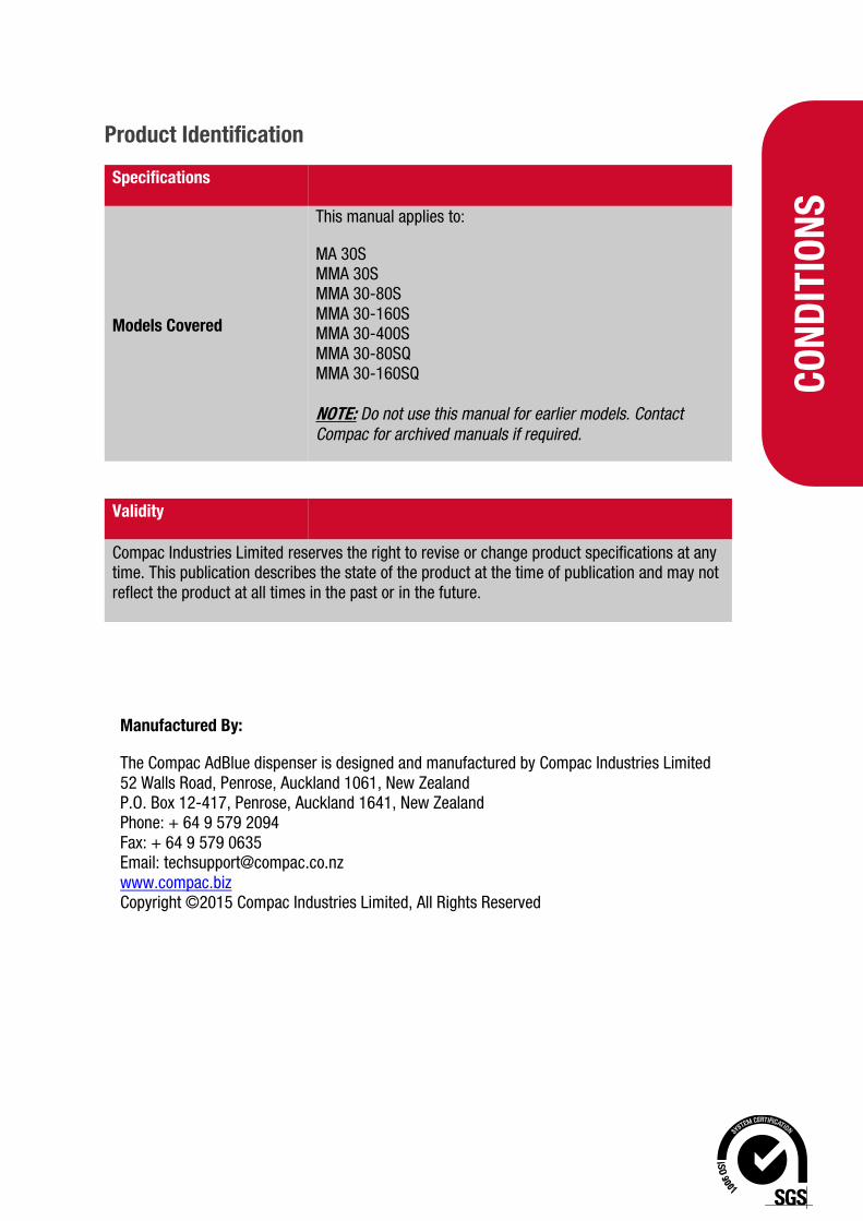
Product Identification
Specifications
Models Covered
This manual applies to:
MA 30S MMA 30S MMA 30-80S MMA 30-160S MMA 30-400S MMA 30-80SQ MMA 30-160SQ NOTE: Do not use this manual for earlier models. Contact Compac for archived manuals if required.
Validity
Compac Industries Limited reserves the right to revise or change product specifications at any time. This publication describes the state of the product at the time of publication and may not reflect the product at all times in the past or in the future.
Manufactured By:
The Compac AdBlue dispenser is designed and manufactured by Compac Industries Limited 52 Walls Road, Penrose, Auckland 1061, New Zealand P.O. Box 12-417, Penrose, Auckland 1641, New Zealand Phone: + 64 9 579 2094 Fax: + 64 9 579 0635 Email: [email protected] www.compac.biz Copyright ©2015 Compac Industries Limited, All Rights Reserved

Document Control
Document Control
Document Information
Manual Title AdBlue Master V50 Installation Manual
Current Revision Author(s) V Amarakoon
Original Publication Date 7 July 2015
Authorised By W Zheng
Revision History
Version Date Author(s) Revision Notes
1.0.0 7 July 2015 R Lacey New installation sheet based on V50 mass flow meter
1.0.1 7 October 2015 R Lacey Added AdBlue specific service procedures and revised purge instructions.
1.0.2 21 December 2017 S Laycock Reformatted Manual
1.0.3 15 November 2018 S Laycock Added MMA 30-160SQ footprint
1.0.4 4 February 2019 R Liu Updated contact information and electrical connections
1.0.5 20 February 2019 R Liu Updated Electronics Layout
1.0.6 27 February 2019 S Laycock Updated electrical connections
1.0.7 28 November 2019 V Amarakoon
Updated MMA30-160SQ 3Hose and MMA30-160SQ 4Hose footprints. Added MMA30-80SQ 3Hose footprint.
1.0.8 29 July 2020 V Amarakoon Updated the power supply diagram
Cont
ents
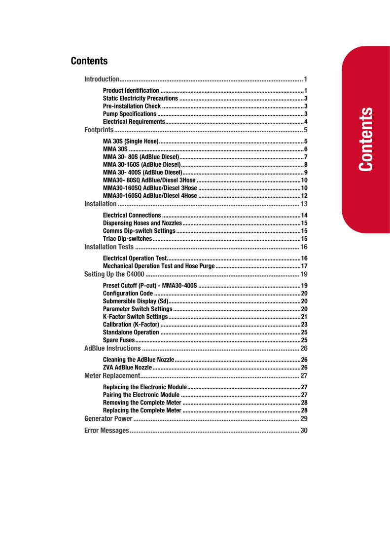
Contents
Introduction .......................................................................................................... 1
Product Identification ........................................................................................... 1 Static Electricity Precautions ............................................................................... 3 Pre-installation Check .......................................................................................... 3 Pump Specifications ............................................................................................. 3 Electrical Requirements ........................................................................................ 4
Footprints ............................................................................................................. 5
MA 30S (Single Hose) ............................................................................................ 5 MMA 30S ............................................................................................................... 6 MMA 30- 80S (AdBlue Diesel) ............................................................................... 7 MMA 30-160S (AdBlue Diesel) .............................................................................. 8 MMA 30- 400S (AdBlue Diesel) ............................................................................. 9 MMA30- 80SQ AdBlue/Diesel 3Hose .................................................................. 10 MMA30-160SQ AdBlue/Diesel 3Hose ................................................................. 10 MMA30-160SQ AdBlue/Diesel 4Hose ................................................................. 12
Installation ......................................................................................................... 13
Electrical Connections ........................................................................................ 14 Dispensing Hoses and Nozzles ........................................................................... 15 Comms Dip-switch Settings ............................................................................... 15 Triac Dip-switches .............................................................................................. 15
Installation Tests ............................................................................................... 16
Electrical Operation Test ..................................................................................... 16 Mechanical Operation Test and Hose Purge ...................................................... 17
Setting Up the C4000 ......................................................................................... 19
Preset Cutoff (P-cut) - MMA30-400S ................................................................. 19 Configuration Code ............................................................................................. 20 Submersible Display (Sd).................................................................................... 20 Parameter Switch Settings ................................................................................. 20 K-Factor Switch Settings .................................................................................... 21 Calibration (K-Factor) ......................................................................................... 23 Standalone Operation ......................................................................................... 25 Spare Fuses ......................................................................................................... 25
AdBlue Instructions ........................................................................................... 26
Cleaning the AdBlue Nozzle ................................................................................ 26 ZVA AdBlue Nozzle .............................................................................................. 26
Meter Replacement ............................................................................................ 27
Replacing the Electronic Module ........................................................................ 27 Pairing the Electronic Module ............................................................................ 27 Removing the Complete Meter ........................................................................... 28 Replacing the Complete Meter ........................................................................... 28
Generator Power ................................................................................................ 29
Error Messages .................................................................................................. 30
1.
Introduction
Introduction
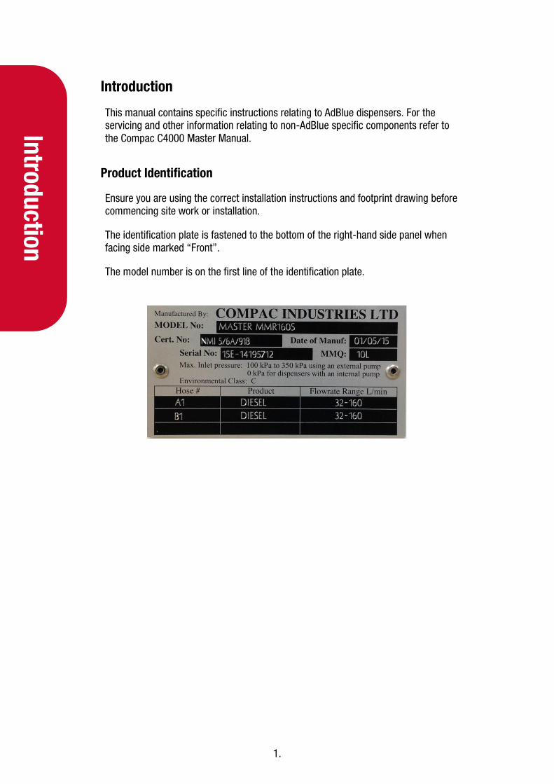
This manual contains specific instructions relating to AdBlue dispensers. For the servicing and other information relating to non-AdBlue specific components refer to the Compac C4000 Master Manual.
Product Identification
Ensure you are using the correct installation instructions and footprint drawing before commencing site work or installation.
The identification plate is fastened to the bottom of the right-hand side panel when facing side marked “Front”.
The model number is on the first line of the identification plate.

2.
Intr
oduc
tion
Understanding the Model Number:
The model number for Master dispensers is split into: Chassis style, hose configuration, pump or dispenser and specific application.
Use the table below to help identify the unit.
Style L/min per hose Pump style Options
MA = single hose
MA30 = one hose @ 30 l/min P = pump Blank = Standard
MMA = multi hose
MMA30 = two hoses @ 30 l/min
S = dispenser Avi = Aviation
MMA30-160 = side A 30 l/min (AdBlue), side B 160 l/min diesel
Marine = Marine
For example: MMA-30-80S is a two hose unit. Hose side A is 30 l/min AdBlue, side B is 80 l/min diesel and the unit is a dispenser (with external pumps).
NOTE: Make sure you use the footprint that relates exactly to your model.

3.
Introduction
Static Electricity Precautions
Electronic components used are sensitive to static. Please take anti-static precautions.
An anti-static wrist strap should be worn and connected correctly when working on any electronic equipment. If an anti-static wrist strap is unavailable, or in an emergency, hold onto an earthed part of the pump/dispenser frame whilst working on the equipment. This is not a recommended alternative to wearing an anti-static wrist strap.
NOTE: Compac Industries Limited reserves the right to refuse to accept any circuit boards returned, if proper anti-static precautions have not been taken.
Pre-installation Check
Once the pump is received on site, check that no damage has occurred while in transit – in particular, damage to electronics due to vibration or jarring. All terminals and plugs should be checked, including IC chips to ensure they are securely in place.
Pump Specifications
The AdBlue supply pump must be AdBlue compatible. It must either have flooded suction or be fitted with an air separation device to eliminate air prior to the dispenser.
Ensure the supply pump pressure does not exceed the rated pressure of the nozzle.
Refer to the diagram below:
NOTE: Pumps must be rated for AdBlue.

4.
Intr
oduc
tion
Electrical Requirements
Power cable: 3 Core Steel Wire Armour Cable 2.5mm2
Core 1: 230 Volt Supply (Active). Core 2: Neutral. Core 3: Earth.
Dispenser power requirements: 220 - 240 Volts. 50 Hz, +/-10%
Current draw: 25W Idle, 200W with all solenoids active.
Communications cable: 2 Core Steel Wire Armour Cable 1.5 mm2. Maximum cable length 100 m. 12 V current loop. For connecting to controller or other dispensers (option).
Submersible pump(s): Suitable cable for 230V solenoid switching current. 300mA maximum load. Do not wire submersible pumps directly to C4000 power supply.
Prior to pump installation, ensure that there is at least a two-metre tail on all cables.

5.
Footprints
Footprints
MA 30S (Single Hose)
6.
Foot
prin
ts
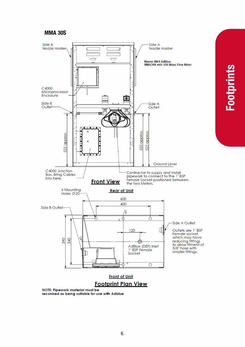
MMA 30S
7.
Footprints
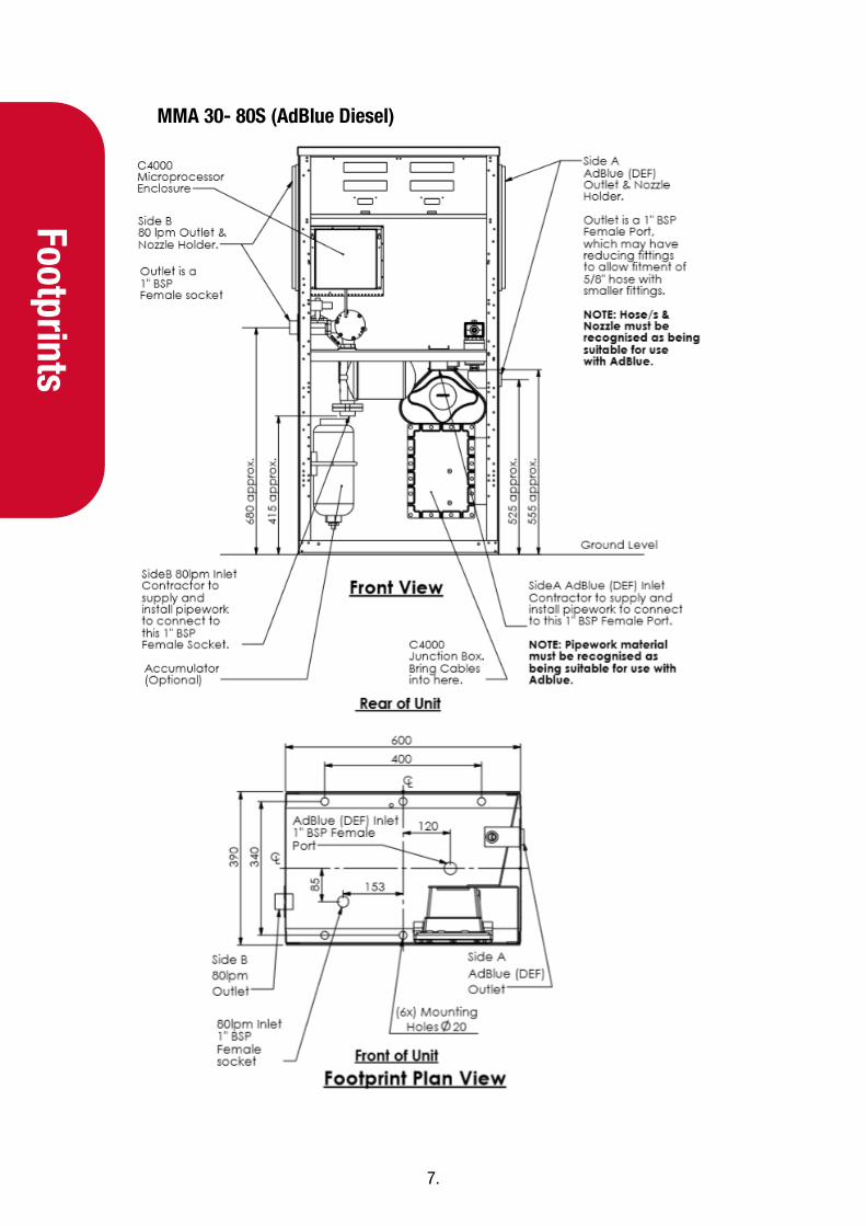
MMA 30- 80S (AdBlue Diesel)
8.
Foot
prin
ts
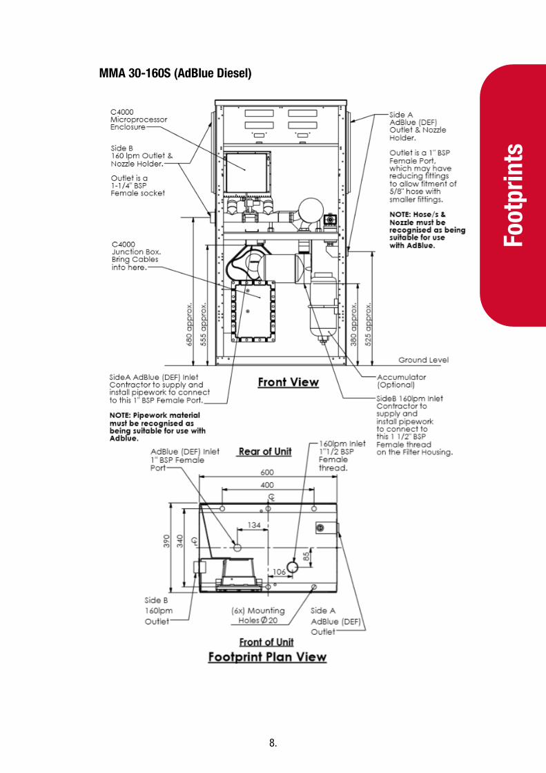
MMA 30-160S (AdBlue Diesel)

9.
Footprints
MMA 30- 400S (AdBlue Diesel)

10.
Foot
prin
ts
MMA30- 80SQ AdBlue/Diesel 3Hose
11.
Footprints
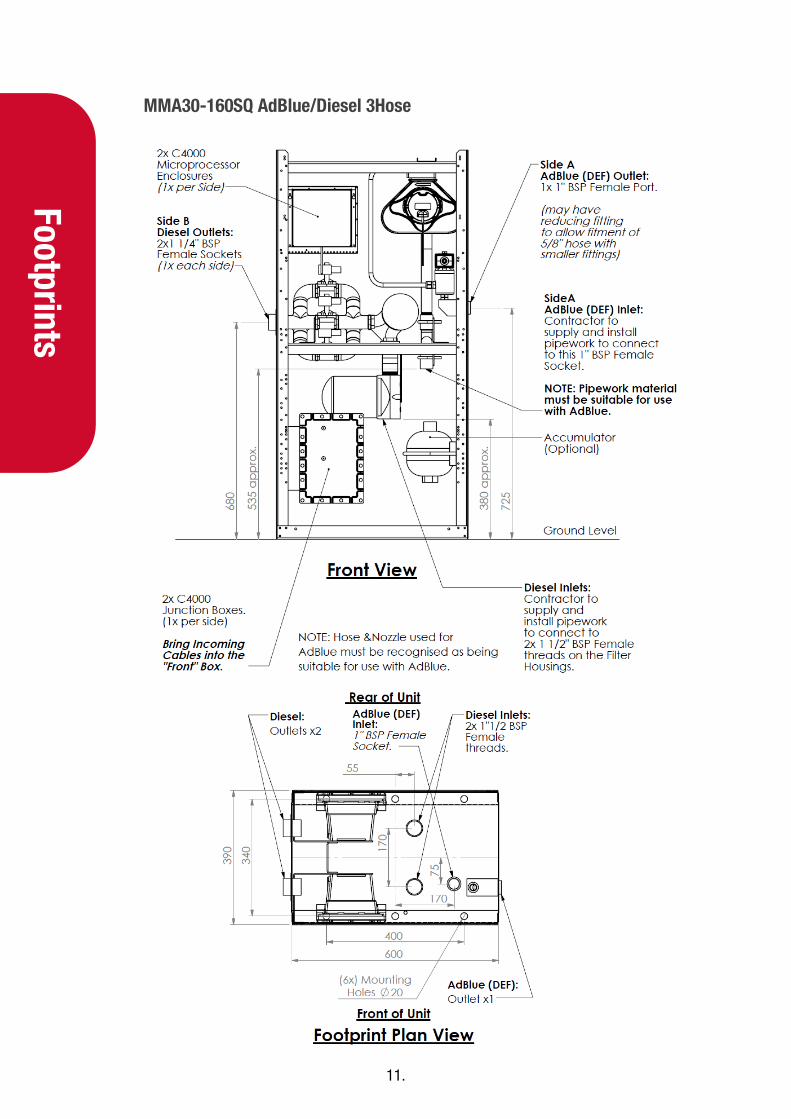
MMA30-160SQ AdBlue/Diesel 3Hose

12.
Foot
prin
ts
MMA30-160SQ AdBlue/Diesel 4Hose

13.
Installation
Installation
Installation should be in accordance with local regulations.
The dispensing equipment shall be installed to prevent the delivery hose from contacting the ground when not in use.
Dispensers should be mounted on a solid, level surface and secured using the fastening holes as shown in the footprint drawings. It is up to the installer to select appropriate fastenings for the application.
Where local regulations for flammable substances require a sump to be fitted:
Sumps must be provided at all dispenser installations with secondary containment pipework and at all new installations; and
At all sites with sumps, dispensers should be installed with a liquid level detection device fitted in the sump that will raise an alarm if liquid is detected in the base of the sump.
Care must be taken when installing pipework to make sure no oil or other contaminants enter the AdBlue lines. Do not use lubricant or thread sealing compounds on AdBlue fittings unless approved for use with AdBlue.
AdBlue is corrosive to aluminium and mild steel. All pipework and fittings that carry AdBlue must be approved for use with it.
While AdBlue is considered non-toxic, it is slightly alkaline. Protect skin and eyes from contact. Flush with water if exposed. Refer to the AdBlue MSDS for further information.
CAUTION: When installing the MMA30- 400 litre per minute high-flow dispenser, be aware that the 400l/min side does not have an internal filtering system fitted at the factory. It is the customer and/or installers responsibility to ensure the fuel supplied to a 400 lpm dispenser is clean and free from any dirt, debris or metal particles that could damage the meter or hydraulic components. A 10 micron filter is recommended. Compac does not warranty the meter or hydraulic components for damage caused by contaminated fuel supply.
14.
Inst
alla
tion
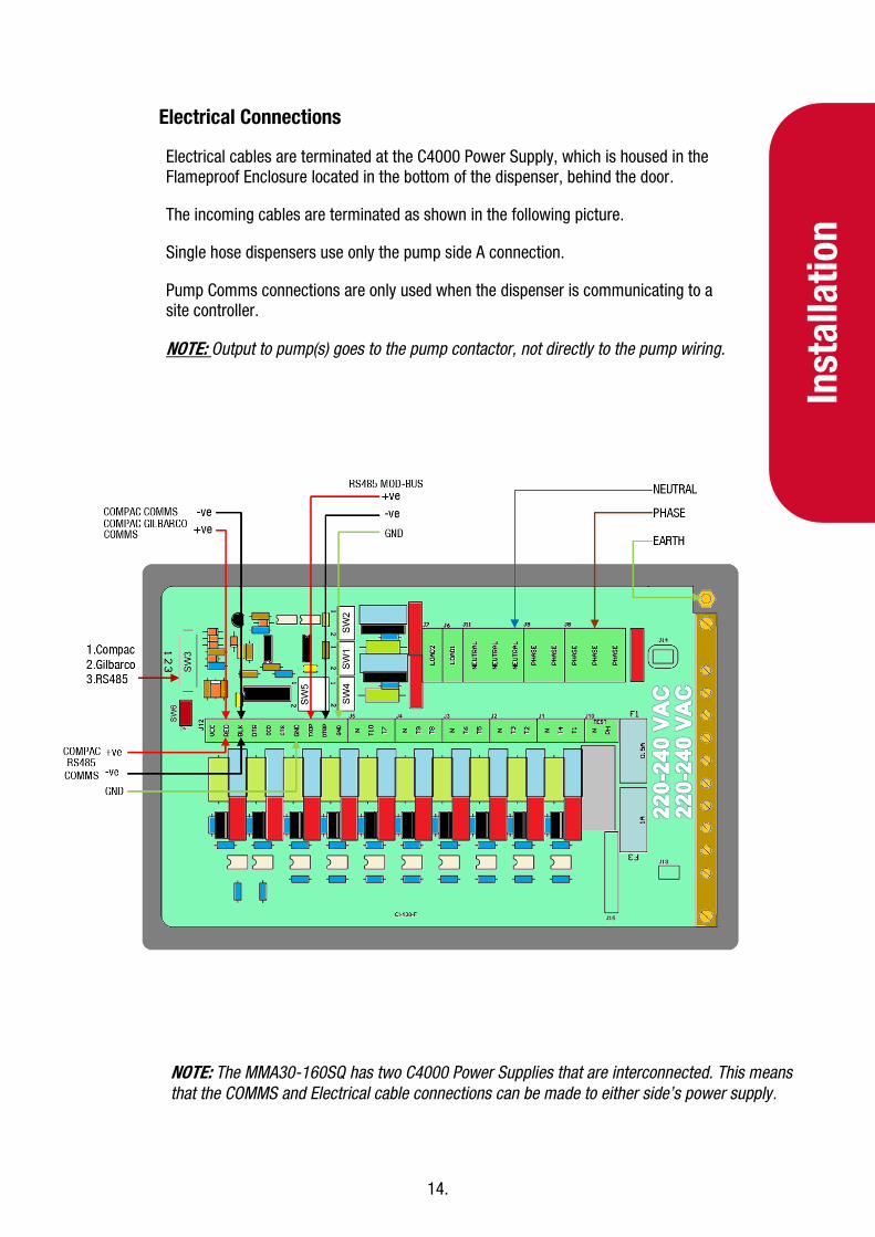
Electrical Connections
Electrical cables are terminated at the C4000 Power Supply, which is housed in the Flameproof Enclosure located in the bottom of the dispenser, behind the door.
The incoming cables are terminated as shown in the following picture.
Single hose dispensers use only the pump side A connection.
Pump Comms connections are only used when the dispenser is communicating to a site controller.
NOTE: Output to pump(s) goes to the pump contactor, not directly to the pump wiring.
NOTE: The MMA30-160SQ has two C4000 Power Supplies that are interconnected. This means that the COMMS and Electrical cable connections can be made to either side’s power supply.

15.
Installation
Dispensing Hoses and Nozzles
The unit may or may not be supplied with dispensing hose and nozzle assemblies.
If customer supplied hose assemblies, pylons, reels, safe breaks and nozzles are used they must comply with the requirements outlined in AS/NZS 2229.
All hoses, nozzles and fittings that come in contact with AdBlue must be compatible with it.
Comms Dip-switch Settings
The actual Comms I/O is controlled by the position of SW3.
SW3 Comms Protocol
Position 1 Compac Standard
Position 2 Gilbarco
Position 3 RS485
Triac Dip-switches
Great care should be taken not to accidentally change the setting of these switches while working in the Flame-proof box. Operating the unit with these incorrectly set can result in damage to the C4000 Power Supply or incorrect operation of the triacs.
These switches are set in the factory and should not be changed.
If they are accidentally changed these are the correct settings for Laser Pump applications.
NOTE: They are 3 position switches
Pump (Motor triac fitted)
SW1 1
SW2 1
SW4 Centre

16.
Inst
alla
tion
Test
s
Installation Tests
Electrical Operation Test
For dispensers with a diesel hose as well as an AdBlue hose, refer to the C4000 manual for testing the diesel side of the dispenser. The instructions below refer to the AdBlue side of the dispenser.
Make sure that the inlet valves are closed (these are the valves in the inlet lines at the base of the dispenser, but not part of the dispenser).
Turn on the power supply to the dispenser.
With the dispenser in a ready state, check that the C4000 Microprocessor Power LED (D1) is turned on.
NOTE: If the dispenser is receiving information from a controller, Comms RXD LED (D6) will poll. If the dispenser responds to polls for its respective pump number/s, Comms TXD LED (D7) will also poll.
Check that Diagnostic LED (D18) slowly flashing. (If the dispenser is connected to an operational Controller, it flashes slowly but erratically. If the dispenser is not connected to a Controller, it flashes slowly and consistently.)
Check that Watchdog LED (D5) is turned off.
Once the display has gone through its test sequence, use the K-Factor switch to check that the fourth digit of the C setting is 4 (AdBlue). 00041 is for a single hose dispenser, 00042 is for a two hose dispenser.
Using the Parameter button put the dispenser into Purge mode by changing the b setting to ***2. Retail dispensers will display Purge in the Dollars display. Commercial dispensers will display a dot on the left hand side of the litres display. The temperature and measured density will toggle in the S/L display. Wait for the C4000 to time out and return to the normal display.
Lift the nozzle.
The display will show “Purge” and the solenoids will energise, starting the pump motor. Check that Diodes D8, D10 and D11 turn on, indicating a signal is being sent to the triacs to open the solenoid valves.
The diagnostic LED (D18) flashes quickly when the start button is pushed or the nozzle removed from the holster to initiate a fill. When the button is released or nozzle returned to the holster it will return to the normal state and flash slowly.
Verify solenoid operation by listening for a click, or by using a screwdriver tip or some other metallic tool to check for a magnetic field present on the solenoid coils.

17.
Installation Tests
The solenoids will switch off after 60 seconds. This is a default time-out for the Purge setting.
Hang the nozzle, and using the Parameter button, put the dispenser into standard mode by changing the b setting to ***0.
For two hose AdBlue dispensers, repeat the procedure for side B. For AdBlue / Diesel dispensers the diesel hose test procedure is the same as the Electrical Operation Test in the C4000 manual.
Re-power the dispenser and the move on to the Mechanical commissioning of the Dispenser.
Mechanical Operation Test and Hose Purge
Make sure that the electrical commissioning tests have been carried out and the solenoid operation has been verified before carrying out the following tests.
Slowly open the supply valves to the dispenser, checking for any leaks.
Turn on the power supply to the dispenser.
Using the Parameter button put the dispenser into Purge mode by changing the b setting to ***2. Retail dispensers will display Purge in the Dollars display. Commercial dispensers will display a dot on the left-hand side of the litres display. The temperature and measured density will toggle in the $/L display. Wait for the C4000 to time out and return to the normal display.
Lift the nozzle.
The display will show Purge and the solenoids will energise, starting the pump motor. Check that Diodes D8, D10 and D11 turn on, indicating a signal is being sent to the triacs to open the solenoid valves.
In Purge mode the dispenser will only operate for 60 seconds at a time before shutting down. If the dispenser shuts down, hang up the nozzle and start again.
Check all the dispenser fittings, solenoids and pipework for leaks.
Slowly dispense AdBlue from the dispenser, being careful to shield yourself from splashes as there may be air in the fuel causing it to spray from the nozzle. If the dispenser stops, hang up the nozzle then remove it start dispensing again.
Continue until the AdBlue flows without any air being present, then hang up the nozzle.
Put the dispenser back into normal mode by changing the b setting back to ***0. On commercial displays check that the dot is no longer on the litres display.
18.
Inst
alla
tion
Test
s
Lift the nozzle and slowly dispense AdBlue from the dispenser. The display and tote should increment when fuel is flowing. If the dispenser stops and the error message AIR displays, go back and purge the hose again.
For two hose AdBlue dispensers, repeat the procedure for side B.
For AdBlue / Diesel dispensers follow the instructions in the C4000 manual for mechanical commissioning of the diesel hose.
The dispenser can now be calibrated. Refer to the C4000 Master Manual for calibration instructions. Setting up the C4000.
Once the pump is connected on site, the final setup check and calibration to complete the installation must be carried out, using the Parameter Switch and Calibration (K-Factor) Switches on the C4000 processor board.
19.
Setting Up the C4000
Setting Up the C4000
Preset Cutoff (P-cut) - MMA30-400S
Some MMA30-400S models with a preset function may be fitted with dual high/low solenoid valves to slow the fuel delivery rate before the preset amount is reached. The C4000 shuts down the high flow 400 l/min solenoid before the preset total is reached, leaving the low flow solenoid to complete the fill. If the setting is too small, the dispenser may overshoot the preset amount, if it is too large, the dispenser may take a long time to complete a fill. The P-cut setting is adjusted using the parameter switch.
A general setting is entered at the factory but if the dispenser is overshooting the preset or it is taking a long time to complete a fill, you may want to change it.
The formula for working out the new P-cut figure for overruns is:
(𝑃𝑟𝑖𝑐𝑒 𝑝𝑒𝑟 𝑙𝑖𝑡𝑟𝑒 ∗ 𝐷𝑜𝑙𝑙𝑎𝑟 𝑎𝑚𝑜𝑢𝑛𝑡 𝑜𝑓 𝑜𝑣𝑒𝑟𝑟𝑢𝑛) + 𝐸𝑥𝑖𝑠𝑡𝑖𝑛𝑔 𝑃 𝑐𝑢𝑡 𝑓𝑖𝑔𝑢𝑟𝑒
The figure should be rounded to two decimal places.
Example:
▪ Price per litre = $ 2.50 ▪ Overrun = $ 0.15 ▪ Existing P-cut = 0.32
(2.5 ∗ 0.15) + 0.32 = 0.695
The final figure would be 0.70.
For slow final delivery, experiment by reducing the P-cut until an overrun is achieved then using the above formula for a final adjustment.
NOTE: When doing P-cut tests make sure that you are dispensing enough fuel to reach full flow rate.
NOTE: Not all 400 l/min dispensers are equipped with dual solenoids, check the sales order to confirm before attempting to adjust.
To adjust the P-cut, use the K-Factor switch. Scroll through the settings until the price display shows PCut and the volume display shows PC*.**. Select the digits you wish to change and hold down the switch to scroll through until the required change is made. The range is from 0.01 to 9.99 litres.
20.
Setti
ng U
p th
e C4
000
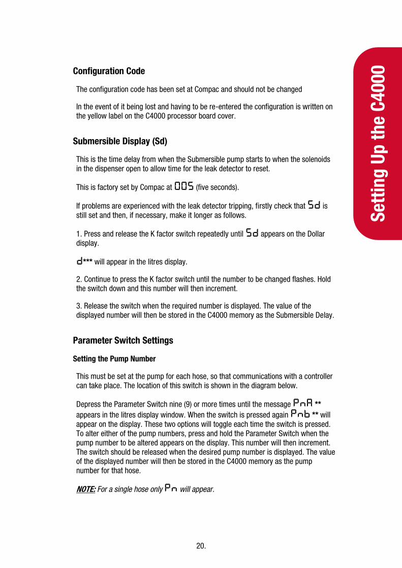
Configuration Code
The configuration code has been set at Compac and should not be changed
In the event of it being lost and having to be re-entered the configuration is written on the yellow label on the C4000 processor board cover.
Submersible Display (Sd)
This is the time delay from when the Submersible pump starts to when the solenoids in the dispenser open to allow time for the leak detector to reset.
This is factory set by Compac at 005 (five seconds).
If problems are experienced with the leak detector tripping, firstly check that 5d is still set and then, if necessary, make it longer as follows.
1. Press and release the K factor switch repeatedly until 5d appears on the Dollar display.
d*** will appear in the litres display.
2. Continue to press the K factor switch until the number to be changed flashes. Hold the switch down and this number will then increment.
3. Release the switch when the required number is displayed. The value of the displayed number will then be stored in the C4000 memory as the Submersible Delay.
Parameter Switch Settings
Setting the Pump Number
This must be set at the pump for each hose, so that communications with a controller can take place. The location of this switch is shown in the diagram below.
Depress the Parameter Switch nine (9) or more times until the message PnA ** appears in the litres display window. When the switch is pressed again Pnb ** will appear on the display. These two options will toggle each time the switch is pressed. To alter either of the pump numbers, press and hold the Parameter Switch when the pump number to be altered appears on the display. This number will then increment. The switch should be released when the desired pump number is displayed. The value of the displayed number will then be stored in the C4000 memory as the pump number for that hose.
NOTE: For a single hose only Pn will appear.

21.
Setting Up the C4000
Setting the Price
Using the Parameter Switch, follow the chart to set the price for the hose(s) in question.
Step ACTION RESULT
1 Ensure that the nozzle is hung up Dispenser in idle state
2 Press and Hold the Parameter switch until the “Price per litre” is displayed.
The price for side A is shown as P**** on the litres display and PrA is displayed on the money display.
3 Press and hold the Parameter switch.
A digit, of the displayed ‘Price per litre’, will begin to increment.
4 When the digit is correct, release the Parameter switch.
5 Repeat steps 3 and 4 for each digit of the ‘Price per litre’.
NOTE: the C4000 will reset itself if the Parameter switch is left for more than 60 seconds.
Continue for Dual hose units
6 Press and release the Parameter switch 8 or more times in quick succession
The price for side B is shown as P**** on the litres display and Prb is displayed on the money display.
7 Repeat steps 3 to 5 above.
K-Factor Switch Settings
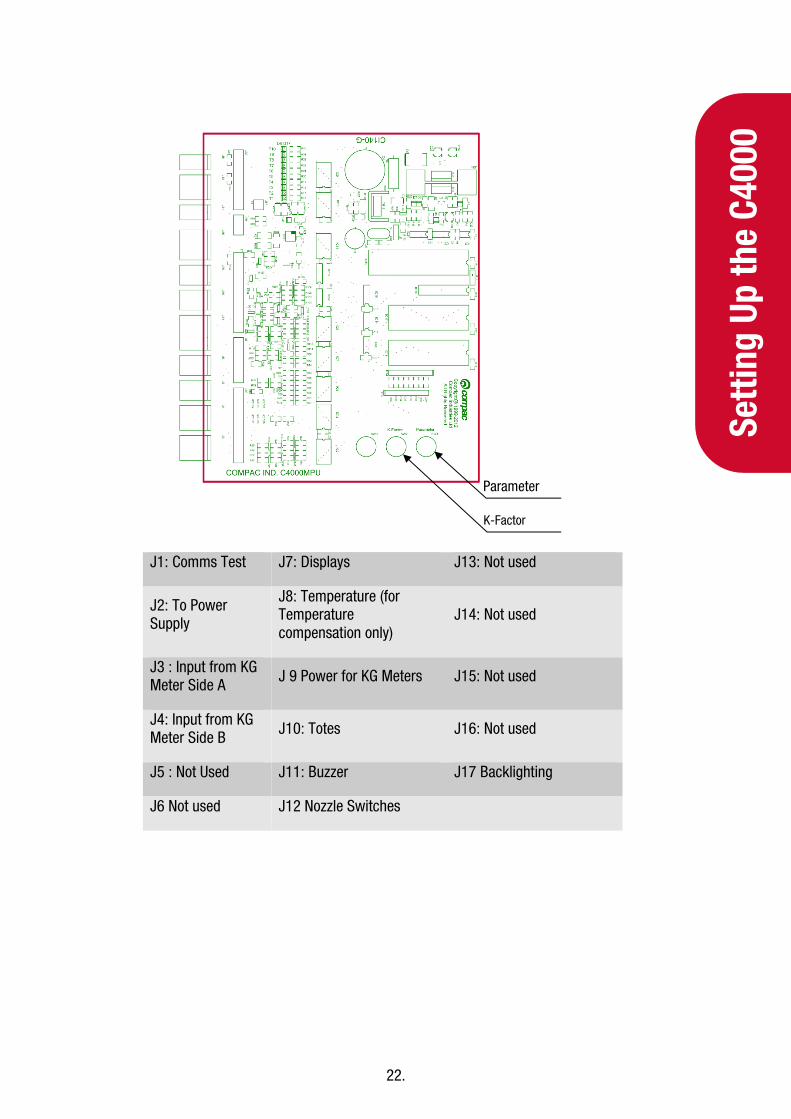
K-Factor, and other various configuration settings, are set via this switch. The position of the K-Factor switch is shown in the diagram below:
K-Factor settings are adjusted by pressing the button to scroll through the available options to find the digit that requires changing, then holding down the switch to scroll through the digits 0-9. Releasing the switch on the required digit will lock it in place. The K-factor display will time-out after 10 seconds and will save the setting. For more details refer to the C4000 manual.
22.
Setti
ng U
p th
e C4
000
J1: Comms Test J7: Displays J13: Not used
J2: To Power Supply
J8: Temperature (for Temperature compensation only)
J14: Not used
J3 : Input from KG Meter Side A J 9 Power for KG Meters J15: Not used
J4: Input from KG Meter Side B J10: Totes J16: Not used
J5 : Not Used J11: Buzzer J17 Backlighting
J6 Not used J12 Nozzle Switches
Parameter
K-Factor

23.
Setting Up the C4000
Calibration (K-Factor)
Setting the K-Factor
K-Factor is a proportional calibration factor of litres dispensed per revolution of the meter.
To calibrate the dispenser/pump, dispense fuel into a certified measuring container, and compare the display value with the amount dispensed.
Example:
Display shows 10.00
True volume 20.00
To calculate the correct 'K' Factor from the information above; firstly, record the existing 'K' Factor.
𝑁𝑒𝑤 𝐾 𝐹𝑎𝑐𝑡𝑜𝑟 = 𝐸𝑥𝑖𝑠𝑡𝑖𝑛𝑔 𝐾 𝐹𝑎𝑐𝑡𝑜𝑟 ∗ 𝐷𝑖𝑠𝑝𝑒𝑛𝑠𝑒𝑑 𝐴𝑚𝑜𝑢𝑛𝑡
𝐷𝑖𝑠𝑝𝑙𝑎𝑦𝑒𝑑 𝐴𝑚𝑜𝑢𝑛𝑡
= 𝐸𝑥𝑖𝑠𝑡𝑖𝑛𝑔 𝐾 𝐹𝑎𝑐𝑡𝑜𝑟 ∗ 20
10
= 𝐸𝑥𝑖𝑠𝑡𝑖𝑛𝑔 𝐾 𝐹𝑎𝑐𝑡𝑜𝑟 ∗ 2
Change the existing 'K' Factor to this new value.
Typical K-Factor Settings
Below is a list of the typical K factor settings in an Adblue dispenser. Please refer to the documentation supplied with your dispenser as there may be slight differences due to meter calibration and dispenser setup.

24.
Setti
ng U
p th
e C4
000
Setting Value Description
F 1.000 Standard K-Factor setting. Adjust when calibrating meter. Refer 19.1 C4000 manual.
Sd 000 Solenoid delay in seconds. Default value is zero
P-Cut 0.00 Preset cut. Set to a larger value if you are having problems with the unit overrunning a preset value.
Sr 0.000 Screen Resolution. Default value is 0.000
b 0000 Set to 1000 to inhibit standalone operation (use ***2 for purge mode)
C 00041 Configuration code. Always set to 00041 (1 hose) or 00042 (2 hose)
Id-A XXXXXX Six-digit number on V50 meter side A (Id-B for 2 hose models)
Other changes from the standard setup include the removal of the no-flow timeout. The meter will automatically time out after 10 seconds of less than 3 litres per minute flow.
Sealing the K-Factor Switch
After calibration the K-Factor switch should be sealed as shown.

25.
Setting Up the C4000
Standalone Operation
In standalone operation, the dispenser will continue working when not connected to a controller. 'Stand-alone' mode being when no authorisation of fills is required and so fills are simply initiated by removing the refuelling assembly from its holder. If standalone operation is inhibited, the dispenser will not work in 'stand-alone' mode, regardless of whether the dispenser is ONLINE to a controller or not.
The dispenser ceases to work in 'stand-alone' mode if connected to a controller, regardless of the position of standalone setting.
Generally, on retail forecourts the dispenser should be set-up for standalone operation. Hence, if the forecourt controller breaks down the dispensers can be set to work in 'stand-alone' mode simply by turning them off then on again.
For unattended refuelling sites, the dispensers should not be able to work in 'stand-alone' mode in the event of a controller failure. Therefore, the dispenser should be set-up to inhibit standalone operation.
This is set in the b code on the K factor switch.
The b code to run Standalone without Dispenser Controller is 0000.
The b code to inhibit Standalone is 1000.
Spare Fuses
In the event of a fuse blowing on the C4000 Power supply a bag of 3 is included in each flameproof box. Any fuses used from this bag should be replaced.
NOTE: There are three different ratings used. If replacing a fuse, ensure that the correct value is used.
26.
AdBl
ue In
stru
ctio
ns
AdBlue Instructions
Cleaning the AdBlue Nozzle
If AdBlue evaporates it may form crystals around the dispenser nozzle. A build up of crystals can block the air passage causing the nozzle to continuously trip off.
If this occurs, rinsing the nozzle in a bucket of warm water will dissolve the crystals and unblock the air passage.
To avoid contamination of the AdBlue, thoroughly dry the nozzle after rinsing.
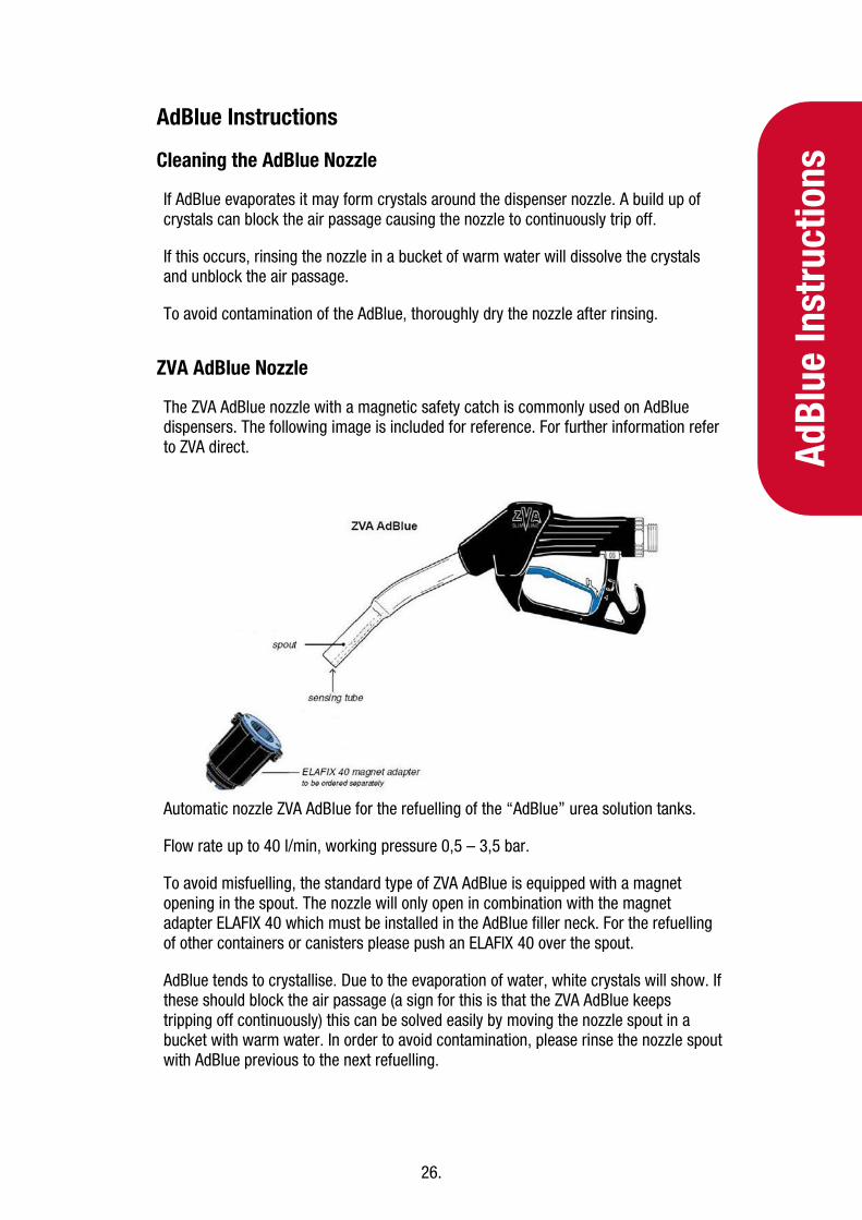
ZVA AdBlue Nozzle
The ZVA AdBlue nozzle with a magnetic safety catch is commonly used on AdBlue dispensers. The following image is included for reference. For further information refer to ZVA direct.
Automatic nozzle ZVA AdBlue for the refuelling of the “AdBlue” urea solution tanks.
Flow rate up to 40 l/min, working pressure 0,5 – 3,5 bar.
To avoid misfuelling, the standard type of ZVA AdBlue is equipped with a magnet opening in the spout. The nozzle will only open in combination with the magnet adapter ELAFIX 40 which must be installed in the AdBlue filler neck. For the refuelling of other containers or canisters please push an ELAFIX 40 over the spout.
AdBlue tends to crystallise. Due to the evaporation of water, white crystals will show. If these should block the air passage (a sign for this is that the ZVA AdBlue keeps tripping off continuously) this can be solved easily by moving the nozzle spout in a bucket with warm water. In order to avoid contamination, please rinse the nozzle spout with AdBlue previous to the next refuelling.

27.
Meter Replacem
ent
Meter Replacement
The V50 meter has a replaceable electronics module. If the meter is not working, replace this. If the meter still does not work the entire meter will need to be replaced.
Replacing the Electronic Module
The electronic module can be replaced without removing the meter from the dispenser.
1. Turn the power off the dispenser. 2. Remove the side panel to access the meter. 3. Undo the four retaining screws on the front of the meter. 4. Snip the sealing wires and remove the electronic module from the meter. 5. Snip any cable ties and noting where it is plugged in and unplug the module
from the C4000 board. 6. Fit the new electronic module to the meter. Feed the cable up to the C4000
board and plug it into the same socket as the old module (the clips face outwards).
7. Cable-tie the new cable in place and fix the module in place with screws and new anti-tamper seals.
Pairing the Electronic Module
The new module needs to be paired to the C4000 board using the K-Factor switch.
1. Start the dispenser and copy down the serial number stuck on the face of the new module.
2. Using the K-Factor switch scroll through the menu until you reach the Id-
A (side A) or Id-b (side B) screen depending on which meter the module has been installed in (dual hose models).
3. By pressing then holding in the K-Factor switch, scroll through each digit in turn until the number matches the number printed on the new module.
4. When you have the correct number continue to scroll through until you leave the Id menu entirely.
NOTE: On two hose units it is important to do this operation even if you are only replacing one module. Failure to do this is one of the prime causes of setup problems. 5. You will now need to calibrate the new module by comparing a dispensed
amount of AdBlue with the displayed amount and adjusting the K-Factor. Refer to the Calibration section of the C4000 manual for details.

28.
Met
er R
epla
cem
ent
Removing the Complete Meter
The entire V50 meter is available as a spare part complete with manifold and electronic module.
CAUTION: When removing the meter, take care to prevent spilling AdBlue onto any electronic component, aluminium or metal surface. Clean up any spillage immediately. Any skin contact should we washed thoroughly with water.
1. Turn off the AdBlue supply to the dispenser. 2. Turn the power off the dispenser. 3. Snip any cable ties and noting where it is plugged in, unplug the meter from
the C4000 board. 4. Undo the six screws holding the meter in place and remove the meter.
Replacing the Complete Meter
1. Make sure the front of the meter containing the electronic module is facing out.
2. Using the six screws, fasten the new meter in place. 3. Feed the meter cable up to the C4000 board and plug it into the same socket.
The clips face outwards. 4. Cable tie the lead neatly out of the way if required. 5. Make sure all connections are tight. 6. Open any valves you may have turned off. 7. Restart the dispenser and pair the new meter to the C4000. 8. Purge the air from the system. 9. Calibrate the new meter.
29.
Generator Power
Generator Power
The power output from onsite generators can cause power spikes that may damage electrical components within the cabinet. When connecting to sites powered by generators, please take the following precautions:
1. Install a power conditioner. Although generators are fitted with power regulators, most are not filtered sufficiently for powering sensitive electrical components. We recommend installing a commercial power conditioner and/or UPS between the generator and the unit.
2. Before starting a generator, make sure the power to the unit is turned off. 3. Start the generator, let the generator reach stable operating speed and wait 30
seconds before reconnecting the power to the unit. 4. For units where the generator starts and stops on demand, install a delay
timer or PLC to automatically isolate the unit until the operating speed and consistent power output is achieved.
5. Isolate the unit before shutting down the generator.
30.
Erro
r Mes
sage
s
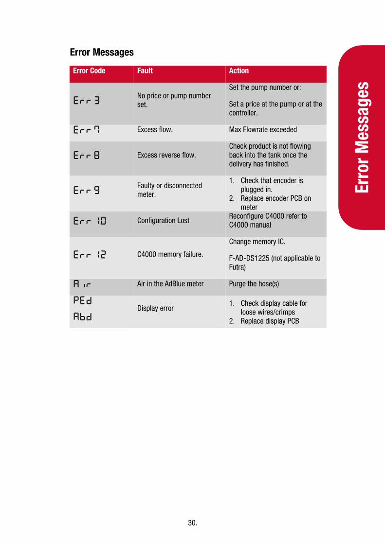
Error Messages
Error Code Fault Action
Err 3 No price or pump number set.
Set the pump number or:
Set a price at the pump or at the controller.
Err 7 Excess flow. Max Flowrate exceeded
Err 8 Excess reverse flow. Check product is not flowing back into the tank once the delivery has finished.
Err 9 Faulty or disconnected meter.
1. Check that encoder is plugged in.
2. Replace encoder PCB on meter
Err 10 Configuration Lost Reconfigure C4000 refer to C4000 manual
Err 12 C4000 memory failure.
Change memory IC.
F-AD-DS1225 (not applicable to Futra)
Air Air in the AdBlue meter Purge the hose(s)
Ped
Abd Display error
1. Check display cable for loose wires/crimps
2. Replace display PCB