Adaptive Q–V Scheme for the Voltage Control of a DFIG-Based Wind Power...
14
3586 IEEE TRANSACTIONS ON POWER ELECTRONICS, VOL. 31, NO. 5, MAY2016 Adaptive Q–V Scheme for the Voltage Control of a DFIG-Based Wind Power Plant Jinho Kim, Student Member, IEEE, Jul-Ki Seok, Senior Member, IEEE, Eduard Muljadi, Fellow, IEEE, and Yong Cheol Kang, Senior Member, IEEE Abstract—Wind generators within a wind power plant (WPP) will produce different amounts of active power because of the wake effect, and therefore, they have different reactive power capabili- ties. This paper proposes an adaptive reactive power to the voltage (Q–V) scheme for the voltage control of a doubly fed induction generator (DFIG)-based WPP. In the proposed scheme, the WPP controller uses a voltage control mode and sends a voltage error signal to each DFIG. The DFIG controller also employs a voltage control mode utilizing the adaptive Q–V characteristics depending on the reactive power capability such that a DFIG with a larger reactive power capability will inject more reactive power to en- sure fast voltage recovery. Test results indicate that the proposed scheme can recover the voltage within a short time, even for a grid fault with a small short-circuit ratio, by making use of the available reactive power of a WPP and differentiating the reactive power in- jection in proportion to the reactive power capability. This will, therefore, help to reduce the additional reactive power and ensure fast voltage recovery. Index Terms—Adaptive Q–V characteristic, doubly fed induc- tion generator (DFIG), reactive power capability, voltage control of a WPP, wake effect. NOMENCLATURE u dc DC-link voltage. u r ref Reference voltage at rotor circuit. u g ref Reference voltage at grid-side converter (GSC). u i Measured voltage at the terminal of the ith doubly fed induction generator (DFIG). u ref Reference voltage at a point of interconnection (POI). u i ref Reference voltage of the ith DFIG. u POI Voltage at a POI. Δu i ref Voltage error signal. U s ,U r Steady-state stator and rotor voltage. Manuscript received January 22, 2015; revised April 1, 2015 and June 24, 2015; accepted July 30, 2015. Date of publication August 20, 2015; date of cur- rent version December 10, 2015. This work was supported by the National Re- search Foundation of Korea Grant supported by the Korea Government (MSIP) (2010-0028509). NREL’s contribution to this work was supported by the U.S. Department of Energy under Contract DE-AC36-08-GO28308 with the NREL. Recommended for publication by Associate Editor H. Li. J. Kim is with the Department of Electrical Engineering, Chonbuk National University, Jeonju 561-756, Korea (e-mail: [email protected]). J.-K. Seok is with the School of Electrical Engineering, Yeungnam University, Kyungsan 712-749, Korea (e-mail: [email protected]). E. Muljadi is with the National Renewable Energy Laboratory, Golden, CO 80401 USA (e-mail: [email protected]). Y. C. Kang is with the Department of Electrical Engineering, WeGAT Re- search Center, and Smart Grid Research Center, Chonbuk National University, Jeonju 561-756, Korea (e-mail: [email protected]). Color versions of one or more of the figures in this paper are available online at http://ieeexplore.ieee.org. Digital Object Identifier 10.1109/TPEL.2015.2464715 U dr Direct axis rotor voltage. ΔU Perturbed voltage at the terminal of a DFIG. U grid Grid voltage. i ds ,i dr Direct axis stator and rotor current. i qs ,i qr Quadrature axis stator and rotor current. i s ,i r Stator and rotor current. i g ,i i GSC and terminal current of the ith DFIG. i dr ref Reference direct axis rotor current. i qr ref Reference quadrature axis rotor current. I s ,I r Steady-state stator and rotor current. ω r Rotor angular frequency. P i , P i ref Active power and reference active power of the ith DFIG. Q G ,Q D Reactive power and reactive power disturbance at the ith DFIG. Q o ,U o Resultant reactive power and voltage at the ith DFIG. Q i ,Q i ref Measured reactive power and reference reactive power of the ith DFIG. Q i max ,Q i min Available maximum and minimum reactive power of the ith DFIG. Δu Range around the rated voltage of a DFIG. k Qi Adaptive reactive power to the voltage gain. f ,f o System frequency and cut-off frequency of a filter. X ls ,X lr Stator and rotor leakage reactance. X m Magnetizing reactance. l s ,l r Stator and rotor leakage inductance. l m Magnetizing inductance. r s ,r r Stator and rotor resistance. θ Stator voltage angle. θ r Angle difference between stator and rotor direct axis. S Differential operator. a Fault location. s Laplace variable. G i Transfer function. G TR Transfer function of the step-up transformer. G PIi Transfer function of the proportional-integral con- troller. L TR Equivalent inductance referred to primary of the step-up transformer. WG Wind generator. DFIG Doubly fed induction generator. POI Point of interconnection. WPP Wind power plant. Q–V Reactive power to voltage. SCR Short-circuit ratio. 0885-8993 © 2015 IEEE. Personal use is permitted, but republication/redistribution requires IEEE permission. See http://www.ieee.org/publications standards/publications/rights/index.html for more information.
Transcript of Adaptive Q–V Scheme for the Voltage Control of a DFIG-Based Wind Power...

3586 IEEE TRANSACTIONS ON POWER ELECTRONICS, VOL. 31, NO. 5, MAY 2016
Adaptive Q–V Scheme for the Voltage Controlof a DFIG-Based Wind Power Plant
Jinho Kim, Student Member, IEEE, Jul-Ki Seok, Senior Member, IEEE, Eduard Muljadi, Fellow, IEEE,and Yong Cheol Kang, Senior Member, IEEE
Abstract—Wind generators within a wind power plant (WPP)will produce different amounts of active power because of the wakeeffect, and therefore, they have different reactive power capabili-ties. This paper proposes an adaptive reactive power to the voltage(Q–V) scheme for the voltage control of a doubly fed inductiongenerator (DFIG)-based WPP. In the proposed scheme, the WPPcontroller uses a voltage control mode and sends a voltage errorsignal to each DFIG. The DFIG controller also employs a voltagecontrol mode utilizing the adaptive Q–V characteristics dependingon the reactive power capability such that a DFIG with a largerreactive power capability will inject more reactive power to en-sure fast voltage recovery. Test results indicate that the proposedscheme can recover the voltage within a short time, even for a gridfault with a small short-circuit ratio, by making use of the availablereactive power of a WPP and differentiating the reactive power in-jection in proportion to the reactive power capability. This will,therefore, help to reduce the additional reactive power and ensurefast voltage recovery.
Index Terms—Adaptive Q–V characteristic, doubly fed induc-tion generator (DFIG), reactive power capability, voltage controlof a WPP, wake effect.
NOMENCLATURE
udc DC-link voltage.ur ref Reference voltage at rotor circuit.ug ref Reference voltage at grid-side converter (GSC).ui Measured voltage at the terminal of the ith doubly
fed induction generator (DFIG).uref Reference voltage at a point of interconnection
(POI).ui
ref Reference voltage of the ith DFIG.uPOI Voltage at a POI.Δui
ref Voltage error signal.Us ,Ur Steady-state stator and rotor voltage.
Manuscript received January 22, 2015; revised April 1, 2015 and June 24,2015; accepted July 30, 2015. Date of publication August 20, 2015; date of cur-rent version December 10, 2015. This work was supported by the National Re-search Foundation of Korea Grant supported by the Korea Government (MSIP)(2010-0028509). NREL’s contribution to this work was supported by the U.S.Department of Energy under Contract DE-AC36-08-GO28308 with the NREL.Recommended for publication by Associate Editor H. Li.
J. Kim is with the Department of Electrical Engineering, Chonbuk NationalUniversity, Jeonju 561-756, Korea (e-mail: [email protected]).
J.-K. Seok is with the School of Electrical Engineering, Yeungnam University,Kyungsan 712-749, Korea (e-mail: [email protected]).
E. Muljadi is with the National Renewable Energy Laboratory, Golden, CO80401 USA (e-mail: [email protected]).
Y. C. Kang is with the Department of Electrical Engineering, WeGAT Re-search Center, and Smart Grid Research Center, Chonbuk National University,Jeonju 561-756, Korea (e-mail: [email protected]).
Color versions of one or more of the figures in this paper are available onlineat http://ieeexplore.ieee.org.
Digital Object Identifier 10.1109/TPEL.2015.2464715
Udr Direct axis rotor voltage.ΔU Perturbed voltage at the terminal of a DFIG.Ugrid Grid voltage.ids ,idr Direct axis stator and rotor current.iqs ,iqr Quadrature axis stator and rotor current.is ,ir Stator and rotor current.ig ,ii GSC and terminal current of the ith DFIG.idr ref Reference direct axis rotor current.iqr ref Reference quadrature axis rotor current.Is ,Ir Steady-state stator and rotor current.ωr Rotor angular frequency.P i , P i
ref Active power and reference active power of theith DFIG.
QG ,QD Reactive power and reactive power disturbance atthe ith DFIG.
Qo ,Uo Resultant reactive power and voltage at the ithDFIG.
Qi ,Qiref Measured reactive power and reference reactive
power of the ith DFIG.Qi
max ,Qimin Available maximum and minimum reactive power
of the ith DFIG.Δu Range around the rated voltage of a DFIG.kQi Adaptive reactive power to the voltage gain.f ,fo System frequency and cut-off frequency of a filter.Xls ,Xlr Stator and rotor leakage reactance.Xm Magnetizing reactance.ls ,lr Stator and rotor leakage inductance.lm Magnetizing inductance.rs ,rr Stator and rotor resistance.θ Stator voltage angle.θr Angle difference between stator and rotor direct
axis.S Differential operator.a Fault location.s Laplace variable.Gi Transfer function.GTR Transfer function of the step-up transformer.GPIi Transfer function of the proportional-integral con-
troller.LTR Equivalent inductance referred to primary of the
step-up transformer.WG Wind generator.DFIG Doubly fed induction generator.POI Point of interconnection.WPP Wind power plant.Q–V Reactive power to voltage.SCR Short-circuit ratio.
0885-8993 © 2015 IEEE. Personal use is permitted, but republication/redistribution requires IEEE permission.See http://www.ieee.org/publications standards/publications/rights/index.html for more information.

KIM et al.: ADAPTIVE Q–V SCHEME FOR THE VOLTAGE CONTROL OF A DFIG-BASED WIND POWER PLANT 3587
RSC Rotor-side converter.GSC Grid-side converter.
I. INTRODUCTION
W IND generation has become one of the most competitiverenewable energy sources. The global installed capacity
of wind generators (WGs) had increased to 318 GW by the end of2013 and could reach 2000 GW by 2030, and wind power couldprovide 25% to 30% of the global electricity supply by 2050 [1].Variable-speed WGs, which employ power conversion devices,have been widely used because of their enhanced controllabilityto provide active power, reactive power, frequency, and voltagecontrol [2]–[6]. The doubly fed induction generator (DFIG), apopular variable-speed WG, shares approximately 50% of thewind energy market [7], [8].
For stable operation of a power grid, the voltages at all busesshould be kept within a specified range during normal opera-tion or disturbances. To achieve this, the voltage at a node iscontrolled by a generator or reactive power compensating unitclosest to the applicable node. Thus, in the case of a powergrid with high wind penetration, the voltage at the point of in-terconnection (POI) of a wind power plant (WPP) should bemaintained whenever disturbance occurs [9]–[18].
A number of research works on the hierarchical reactivepower control [19], [20] or voltage control schemes [21]–[24]of a WPP have been reported. In [19] and [20], a reactive powercontrol mode was used for both WPP and DFIG controllers. Toensure the acceptable voltage level, a reactive power set pointthat considers the reactive power capability of each DFIG wassent to each DFIG. The transient voltage recovery was slow, be-cause a DFIG controller needs a command signal from a WPPcontroller to react in the case of a sudden voltage change.
On the other hand, a voltage control mode was used as aWPP controller in [21]–[24]. A reactive power control modewas used as a DFIG controller, and the required reactive currentset point was sent to a DFIG controller with a weighting factor,which is inversely proportional to the active power production ofeach DFIG [21]. This control scheme adjusts the reactive powerinjection from a DFIG depending on its reactive power capabil-ity. However, the scheme was unable to react to a voltage dipimmediately after a disturbance because of the reactive currentcontrol mode used for the DFIG controllers. Thus, to quickly re-act to a voltage dip, a voltage control mode was used as a DFIGcontroller for fast voltage support [22]–[24]. The static reactivepower to the voltage (Q–V droop control) characteristic, whichdefines the reactive power as a function of the voltage deviation,was used in [22]. The slope of the Q–V characteristics of allDFIGs was set to a fixed value of 6.6.
The fixed Q–V characteristic was used as a WPP controllerin [23] and [24]. The Q–V characteristic with the maximumand minimum reactive power capabilities of 33% of the ratedpower as specified in [25] was used in [23], whereas the typicalslope Q–V relationship was used in [24]. A DFIG controllerdetermined the reactive current reference using a fixed reac-tive current-to-voltage relationship in [23] and a proportional-integral (PI) controller in [24]. These schemes showed fastvoltage support when a large voltage dip occurred; however,
Fig. 1. Typical configuration of a DFIG.
steady-state errors are inevitable for small disturbances becauseof the small Q–V gain, or slope, in the WPP controller.
This paper proposes an adaptive Q–V scheme for the voltagecontrol of a DFIG-based WPP to enhance the transient voltagerecovery capability. A WPP controller calculates the voltageerror value from the reference voltage and measured POI voltageand sends it to each DFIG. A DFIG controller employs a voltagecontrol mode with the adaptive Q–V characteristics dependingon its reactive power capability to ensure fast voltage recovery.The proposed adaptive scheme allows the DFIG with a largerreactive power capability to inject more reactive power, and thus,utilize the available reactive power capability of a WPP. Theperformance of the scheme was investigated for a 100-MW WPPconsisting of 20 units of 5-MW DFIGs under different scenariosof varying wind conditions, short-circuit ratios (SCRs), and faultlocations using an EMTP-RV simulator.
II. CONTROL OF A DFIG
A. Induction Machine and Wind Turbine Model of a DFIG
The DFIG consists of turbine, induction machine, and back-to-back converters [2]–[6] as shown in Fig. 1. In this paper, thetwo-mass model described in [26] is modeled as the mechanicaldynamic model of a wind turbine, and the induction machine ismodeled as an electromagnetic circuit on the dq reference framebased on a wound-rotor machine.
B. Control System of a DFIG
The control system of a DFIG consists of the rotor-side con-verter (RSC) and grid-side converter (GSC) [27], [28]; the for-mer is used to control the stator voltage at a desired value andperform the maximum power point tracking (MPPT) operation;the latter is used to control the DC-link voltage and to inject thereactive power into the grid.
The active power reference for MPPT operation Pref is set to(1), as in [29], in this paper
Pref = kgω3r . (1)
In this paper, the RSC and GSC are modeled as ideal volt-age sources and the voltage references for the voltage sourcesgenerated using PI controllers. DFIGs are normally equippedwith a crowbar to protect the converters from the overcurrent inthe rotor circuit and overvoltage on a dc-link [30]. This deviceshorts the rotor windings through its resisters. In this paper, anactive crowbar was implemented in a DFIG model, as shown inFig. 1.

3588 IEEE TRANSACTIONS ON POWER ELECTRONICS, VOL. 31, NO. 5, MAY 2016
Fig. 2. Steady-state T-equivalent circuit of an induction machine.
C. Reactive Power Capability of a DFIG [31]
The reactive power capability of a DFIG can be obtainedfrom the P–Q diagram, which depends on the active power.This section will briefly describe the derivation of the reactivepower capability of a DFIG from the P–Q diagram that considersthe three constraints: A rotor current, stator current, and rotorvoltage [31]. To do this, the stator voltage is assumed to be 1p.u. by neglecting the impedance of a step-up transformer andcomplex powers from the stator and rotor windings are derivedfrom a steady-state T-equivalent circuit, as shown in Fig. 2.
1) Rotor Current Limit: Complex powers from the stator androtor windings in terms of the rotor current can be representedas
Ss Ir= − |Us |2
(1
Zs + Zm
)∗+ I∗r Us
(Zm
Zs + Zm
)∗(2)
Sr Ir= − |Ir |2 slip
(Zr + Zs)Zm + ZsZr
Zs + Zm
− I∗r Usslip(
Zm
Zs + Zm
). (3)
The reactive power capability of a DFIG due to the rotorcurrent can be obtained by assuming the rotor current with themagnitude of a rated value by varying its angle relative to thestator voltage. Because of the first term in the right-hand sideof (2), the boundary of the reactive power is shifted down; thus,the rotor current is a limiting factor of the upper boundary ofthe resultant P–Q diagram of a DFIG.
2) Stator Current Limit: Complex powers from the stator androtor windings in terms of the stator current can be expressedby
Ss Is= −UsI
∗s (4)
Sr Is= slip
(Zr + Zm
ZmUs −
(Zr + Zs +
ZrZs
Zm
)Is
)
(Us
Zm− Zs + Zm
ZmIs
). (5)
The reactive power capability of a DFIG caused by the statorcurrent can be obtained by assuming the stator current with themagnitude of a rated value by varying its angle relative to thestator voltage. The stator current is a limiting factor of the lowerboundary of the P–Q diagram of a DFIG, because (4) will forma circle with the center at origin and the radius of the product ofthe stator current and the stator voltage.
Fig. 3. Resultant reactive power capability used in this paper. (a) Examplesof P–Q diagram at active powers of 0.30, 0.48, 0.73, and 0.83 p.u. (b) Resultantreactive power capability.
3) Rotor Voltage Limit: Complex powers from the stator androtor windings in terms of the rotor voltage can be described by
Ss Ur= −Us
(Us(Zr + Zm ) − Ur
slip Zm
(Zr + Zs)Zm + ZsZr
)∗
(6)
Sr Ur= −Ur
(UsZm + Ur
slip (Zs + Zm )
(Zr + Zs)Zm + ZsZr
)∗
. (7)
The reactive power capability of a DFIG caused by the rotorvoltage can be obtained by assuming the rotor voltage withthe magnitude of a rated value by varying its angle relative tothe stator voltage. The center of the circle of (6) has a largenegative offset on the imaginary axis, and the radius is inverselyproportional to the slip. However, note that the rotor voltage hasa limiting effect on the upper boundary of the P–Q diagram ofa DFIG only at high absolute values of slips.
4) Reactive Power Capability of a DFIG: P–Q diagrams atsome levels of active power of 0.30, 0.48, 0.73, and 0.83 p.u.can be obtained using (2)–(7) as shown in Fig. 3(a). The upperarcs in each P–Q diagram are determined from (2) and (3); onthe other hand, the lower arcs are obtained from (4) and (5).

KIM et al.: ADAPTIVE Q–V SCHEME FOR THE VOLTAGE CONTROL OF A DFIG-BASED WIND POWER PLANT 3589
TABLE IINDUCTION MACHINE PARAMETER
Symbol Value Unit
Pn 5 MW Nominal active powerSn 6 MVA Nominal apparent powerUs n 2.3 kV Nominal stator voltagers 0.020 Ω Stator resistancels 0.421 mH Stator leakage inductancelm 6.800 mH Magnetizing inductancerr 0.014 Ω Rotor resistancelr 0.374 mH Rotor leakage inductancef 60 Hz System frequency
Fig. 4. Shadow cone of a WG.
The resultant reactive power capability of a DFIG shown inFig. 3(b) is determined by connecting the corner points of eachP–Q diagram at different levels of active power. Table I showsthe parameters of a DFIG used in this paper.
Note that the resultant reactive power capability is derivedby assuming that the stator voltage is remained at a rated value.If it is applied in the transient operation, the reactive powercapability scaled at the stator voltage level can be used.
III. WAKE SPEED CALCULATION
WGs in a WPP generate electricity by extracting energy fromthe wind. This results in a reduction in the wind speed ap-proaching WGs farther downstream. This effect is called thewake effect. WGs within a WPP will have different reactivepower capability because they produce different amounts of ac-tive power because of the wake effect. To develop the propervoltage control scheme of a WPP consisting multiple units ofWGs, the wake effect should be considered [32].
The Jensen model [33] is based on the assumption that thewake flow is linear, as shown in Fig. 4. For simple calculationof the wake speed, this paper employs the Jensen model. Inaddition, wake wind speeds at WGs were calculated using themethod in [34], because it considers the cumulative impact ofmultiple shadowing and the effect of the wind direction.
For a simple case of one WG and its shadow cone, as shown inFig. 4, the wake wind speed vw (x) at the radial distance betweena WG and an arbitrary location, x, vw (x), can be obtained fromthe mass conservation principle, expressed as
πr2rotvw0π(r(x)2 − r2
rot)v0 = πr(x)2vw (x) (8)
where v0 is the free-wind speed, vw0 is the lee-side wind speed,r(x) is the radius of the shadow cone at x, and rrot is the radiusof the upstream WG.
Fig. 5. WPP controller.
In (8), r(x) can be calculated by using
r(x) = rrot + xtanα (9)
where α is an apex factor of the cone.The factor tanα in (9) may have two possible values, depend-
ing on the surface roughness of the wind field. For a free wind,tanα is set to 0.04; otherwise, it should be set to 0.08 [35].
Solving (8) gives vw (x), expressed as
vw (x) =r2rot
r2 vw0 +(
1 − r2rot
r(x)2
)v0
= v0 + (vw0 − v0)(
rrot
r(x)
)2
. (10)
As a general case, it is assumed that a WPP consists of multi-ple units of WGs. In this case, a WG might experience multiplewakes with different degrees of shadowing, depending on thelocation and wind direction. Therefore, the overlapping areabetween the corresponding WGs should be taken into accountwhen calculating the wind speed of a WG. Thus, the resultantwind speed of a WGj , vj , can be obtained by
vj = vj0 −
√√√√√n∑
k=1k �=j
βk (vwk (xkj ) − vj0)2 (11)
where vj0 is the incoming wind speed at WGj without anyshadowing, xkj is the radial distance between WGk and WGj ,vwk (xkj ) is the speed of the wind approaching WGj from theshadowing WGk , βi is the ratio of the area of WGj under theshadow of WGk to its total area, and n is the total number ofWGs.
IV. HIERARCHICAL VOLTAGE CONTROL OF A WPP USING THE
ADAPTIVE Q–V CHARACTERISTICS OF A DFIG
The proposed control scheme aims to make the most of theavailable reactive power of a DFIG to improve the transientvoltage recovery of a WPP. The following sections will describethe WPP and DFIG controllers in detail in the proposed adaptivecontrol scheme.
A. WPP Controller
Fig. 5 shows a WPP controller in the proposed scheme. TheWPP controller adapts a voltage control mode to maintain thePOI voltage as the reference value, uref . To achieve this, theWPP controller sends the reference value Δui
ref to each DFIGwithin the WPP, which is obtained from the error signal betweenuref and measured voltage at the POI uPOI through a PI con-troller. In this paper, Δui
ref ranges from −0.1 to +0.1 p.u. so

3590 IEEE TRANSACTIONS ON POWER ELECTRONICS, VOL. 31, NO. 5, MAY 2016
Fig. 6. DFIG controller.
Fig. 7. Fixed Q–V characteristic based on the minimum reactive power capa-bility used in [22].
that the terminal voltage of each DFIG maintains within ±10%around the rated value. In addition, to provide a smooth changeof Δui
ref , the output of the WPP controller is reset if a resetcontrol is activated; otherwise, it holds the previous value, inthis paper, the dead time is set to 100 ms.
B. DFIG Controller
1) Overall Control Scheme of a DFIG: Fig. 6 shows theRSC controller of the proposed scheme. The RSC controlleralso adapts a voltage control mode to response to a fast voltagechange. As in the control scheme in [22] and [23], the inputsignal of the DFIG controller consists of three terms: Δui
ref , ui ,
and Δuiref , where ui
ref is the voltage set point of the ith DFIGand ui is the measured voltage at the DFIG terminal. However,to generate the reactive power reference Qref , the proposedscheme uses the adaptive Q–V characteristics of DFIGs, whichvaries depending on available reactive power capability of eachDFIG so that DFIGs inject the reactive power in proportional totheir reactive power capability for a disturbance.
On the contrary, in the conventional scheme [22], to generateQref , all DFIGs use the fixed Q–V characteristics shown inFig. 7. The maximum reactive power is set to a fixed value of0.33 p.u., which is the reactive power capability at the maximumactive power output of the DFIG, and the voltage range in thelinear region is ±0.05 p.u. Thus, the Q–V gain of all DFIGs is
set to 6.6, which is fixed at all times. They will inject nearlythe same reactive power, which is similar to or less than thatof the proposed scheme. Moreover, the conventional schemeshows the slow response because of the smaller slope of Q–Vcharacteristic than the proposed scheme. Because DFIGs withinthe WPP have different reactive power capabilities due to thewake effect, the proposed adaptive Q–V scheme can enhance agrid voltage support capability by utilizing the available reactivepower capability of the WPP.
In the proposed scheme, idr ref is obtained through the powerregulator and current limiters. Limits for idr ref are determinedso that it should not exceed the rated current for the RSC, ex-pressed as
idr ref =
⎧⎨⎩
√I2rated − i2qr , umeas ≥ 0.95 p.u.
Irated , umeas < 0.95 p.u.(12)
where Irated is the rated current of the RSC.In this paper, the high priority is given to the quadrature axis
rotor current (or real current) regulation if the terminal voltageof a DFIG is equal to or more than 0.95 p.u. Otherwise, thehigh priority is given to the direct axis rotor current (or reactivecurrent), and the limit value for idr ref is set to Irated .
2) Adaptive Q–V Characteristics of a DFIG Controller: Thissection will describe how the adaptive Q–V characteristic im-plemented in the RSC controller is determined depending onthe reactive power capability, as shown in Fig. 8. The adaptiveQ–V gain kQi in Fig. 8(a) is obtained by
kQi =Qi
max − Qimin
Δu(13)
where Qimax and Qi
min are the available maximum and minimumreactive power of the ith DFIG at a certain active power output,and Δu is the range around the rated voltage, which is set to 0.1in this paper.
The proposed adaptive control scheme allows a DFIG with alarger reactive power capability to inject more reactive power toimprove the transient voltage recovery. As shown in Fig. 8(b),Qi
max and Qimin can be obtained from the predetermined

KIM et al.: ADAPTIVE Q–V SCHEME FOR THE VOLTAGE CONTROL OF A DFIG-BASED WIND POWER PLANT 3591
Fig. 8. Adaptive Q–V characteristics of DFIGs. (a) Q–V scheme implementedin the RSC controller of each DFIG. (b) Setting process for kQ i . (c) Examplesof Q–V characteristic of DFIGs generating different levels of active power.
resultant reactive power capability curve shown in Fig. 3(b),which is implemented in a table function in this paper. Fig. 8(c)shows examples of the adaptive Q–V characteristics of DFIGsgenerating different level of active powers. The red, blue, andblack lines in Fig. 8(c) represent the Q–V characteristics ofDFIG1 , DFIG2 , and DFIG3 , the active powers of which are0.30, 0.48, and 0.73 p.u., respectively. The ranges of the re-active power of DFIG1 , DFIG2 , and DFIG3 are −0.93, 0.55p.u., −0.87, 0.48 p.u., and −0.76 , 0.36 p.u., respectively, andtherefore, kQ1 , kQ2 , and kQ3 are set to 14.78, 13.48, and 11.20respectively. This means that DFIG1 will have more reactivepower capability than DFIG2 and DFIG3 .
3) Stability Analysis of the Proposed Adaptive Q–V ControlScheme: Fig. 9 shows simplified representation of a DFIG in-cluding the proposed adaptive control scheme for the stabilityanalysis by using the root locus method.
To do this, the transfer function from the reactive power refer-ence Qi
ref to the reactive power output of a DFIG Qi is obtainedas
GQ =GPI1GPI2G1G2
1 + GPI2G1 + GPI1GPI2G1G2G3(14)
Fig. 9. Simplified representation of a DFIG including the proposed adaptivecontrol scheme for the stability analysis.
TABLE IICONTROLLER GAINS
Proportional Gain(KP )
Integral Gain(KI )
Windup Gain(Ka )
Power Regulator1 0.2 10 5Power Regulator2 1 40 1Current Regulator1 0.3 5 –Current Regulator2 0.3 5 –WPP Controller 0.2 10 5
where GPI1 and GPI2 are the transfer functions of the powerregulatior1 and current regulator1 , respectively; G1 and G2 arethe transfer functions of a generator, and G3 is the transferfunctions of the filter, and G1 , G2 , and G3 are represented asfollows:
G1(s) = − r2s + l2s
rr r2s + rr l2s + sl2m rs
1 + s 2rs ls2πf (r 2
s −l2s )
1 + s 2rs rr ls + lr r 2s −l2m ls + lr l2s
2πf (rr r 2s +rr l2s +slipl2m rs )
(15)
G2(s) =lm (ls + rs)(r2
s + l2s )
1 + s rs
2πf (rs + ls )
1 + s 2ls rs
2πf (r 2s + l2s )
(16)
G3(s) =(2πfo)2
s2 +√
2(2πfo)2s + (2πfo)2(17)
where fo is the cut-off frequency of the filter and was set to5 kHz in this paper; this paper uses G1(s) and G2(s) derivedin [36].
In addition, the transfer function of the step-up transformeris given by
GTR(s) = LTRs (18)
where LTR is the equivalent inductance of the step-up trans-former referred to primary and is set to 0.23 mH, which isobtained by using Table III.
Finally, the transfer function from the voltage reference Uiref
to the perturbed voltage at the terminal of the DFIG ΔU can berepresented as
GU =kQiGQGTR
1 + kQiGQGTRG4(19)
where G4 is the transfer function of the filter and is set to be thesame as G3 .
For the stability analysis of the proposed adaptive controlscheme, (19) was used to plot the root locus by varying kQi .To do this, it is assumed that the DFIG is performing MPPT

3592 IEEE TRANSACTIONS ON POWER ELECTRONICS, VOL. 31, NO. 5, MAY 2016
TABLE IIIPARAMETERS OF TRANSFORMERS AND CABLES IN THE MODEL SYSTEM
Tr.1 (Y/Δ ) Tr.2 (Δ /Y) Tr. (Y/Y)
Capacity (MVA) 7.2 72 150Frequency (Hz) 60 60 60Turns Ratio (kV) 2.3/33 33/154 154/345% Impedance (p.u.) 0.07 0.07 0.07
Cable1 Cable2 Cable3 Cable4
Resistance (Ω /km) 0.344 0.130 0.064 0.056Reactance (Ω /km) 0.172 0.148 0.132 0.151Capacitance (μF/km) 0.117 0.160 0.209 0.141Rated Voltage (kV) 33 33 33 154Cross-Section Area (mm2) 70 185 400 500
Fig. 10. Root loci of a DFIG including the proposed adaptive gain scheme.(a) Root locus of (19) for the slip of 0.3 (b) Root locus of (19) for the slip of−0.2.
operation and the slip ranges from −0.2 to 0.3; in addition, kQi
ranges from 6.6 to 16.0. Fig. 10 shows the two root loci for thetwo different slips of 0.3 and−0.2 by varying kQi from 0 to 100.Note that in both loci, the poles of the DFIG are located in theleft-half plane. Thus, we can deduce that the DFIG including theproposed control scheme ensures stable operation for the wholerange of the adaptive gains.
V. CASE STUDIES
To investigate the performance of the proposed scheme, amodel system was chosen that includes a WPP and a grid, asshown in Fig. 11. The WPP consists of 20 units of 5-MW/6MVA DFIGs. Four DFIGs are connected to each feeder throughthe 2.3/33-kV transformer. Five collector feeders are connectedto the 33/154-kV substation transformer through the 33-kV sub-marine cables and then to the POI through a 10-km-long 154-kV submarine cable. The distance between the two neighboringDFIGs is set to 1-km. The power–wind speed curve of a DFIGused in this paper is shown in Fig. 12. It is assumed that the
Fig. 11. Model system.
Fig. 12. Power–wind speed curve of a DFIG.
TABLE IVWIND SPEEDS (IN M/S) AT ALL WGS IN THE WPP
10 m/s, Direction 0°, for Case 1 and 12 m/s, Direction 45°, for Case 2 andCase 4 Case 3
Col. 1 Col. 2 Col. 3 Col. 4 Col. 1 Col. 2 Col. 3 Col. 4
10.00 7.75 7.48 7.39 12.00 10.04 9.85 9.7910.00 7.75 7.48 7.39 12.00 10.04 9.85 9.7910.00 7.75 7.48 7.39 12.00 10.04 9.85 9.8510.00 7.75 7.48 7.39 12.00 10.04 10.04 10.0410.00 7.75 7.48 7.39 12.00 12.00 12.00 12.00
WPP controller sends a reference signal to the DFIG controllerat a rate of 0.1 s. Each DFIG controller samples the voltageand current at both stator side and rotor side at the samplingfrequency of 10 kHz; a WPP controller also samples the POIvoltage at the sampling frequency of 10 kHz; all the measuredvoltages and currents are passed through a second-order an-tialiasing low-pass filter with a cut-off frequency of 5 kHz (halfthe sampling frequency) to the WPP and DFIG controllers.
The performance of a WPP voltage control scheme dependson various factors: The reactive power capability of a WPP, gridstiffness, fault location (a), and kinds of disturbances. Thus,the performance of the proposed adaptive control scheme wasinvestigated by varying wind conditions and the SCR for variousdisturbances, and the effect of the different a at a certain SCRwas analyzed as well.
Tables II–IV show gains for the proposed controllers, param-eters of transformers and cables in the model system, and the

KIM et al.: ADAPTIVE Q–V SCHEME FOR THE VOLTAGE CONTROL OF A DFIG-BASED WIND POWER PLANT 3593
Fig. 13. Results for Case 1. (a) Voltage at the POI. (b) Reactive powers into the POI. (c) Reactive power of DFIGs (fixed Q–V). (d) Reactive power of DFIGs(adaptive Q–V). (e) Active power of DFIGs. (f) Q–V gain of DFIGs. (g) Reactive power of DFIG1 . (h) Reactive power of DFIG4 . (i) Terminal voltages of DFIGsand POI.
3594 IEEE TRANSACTIONS ON POWER ELECTRONICS, VOL. 31, NO. 5, MAY 2016
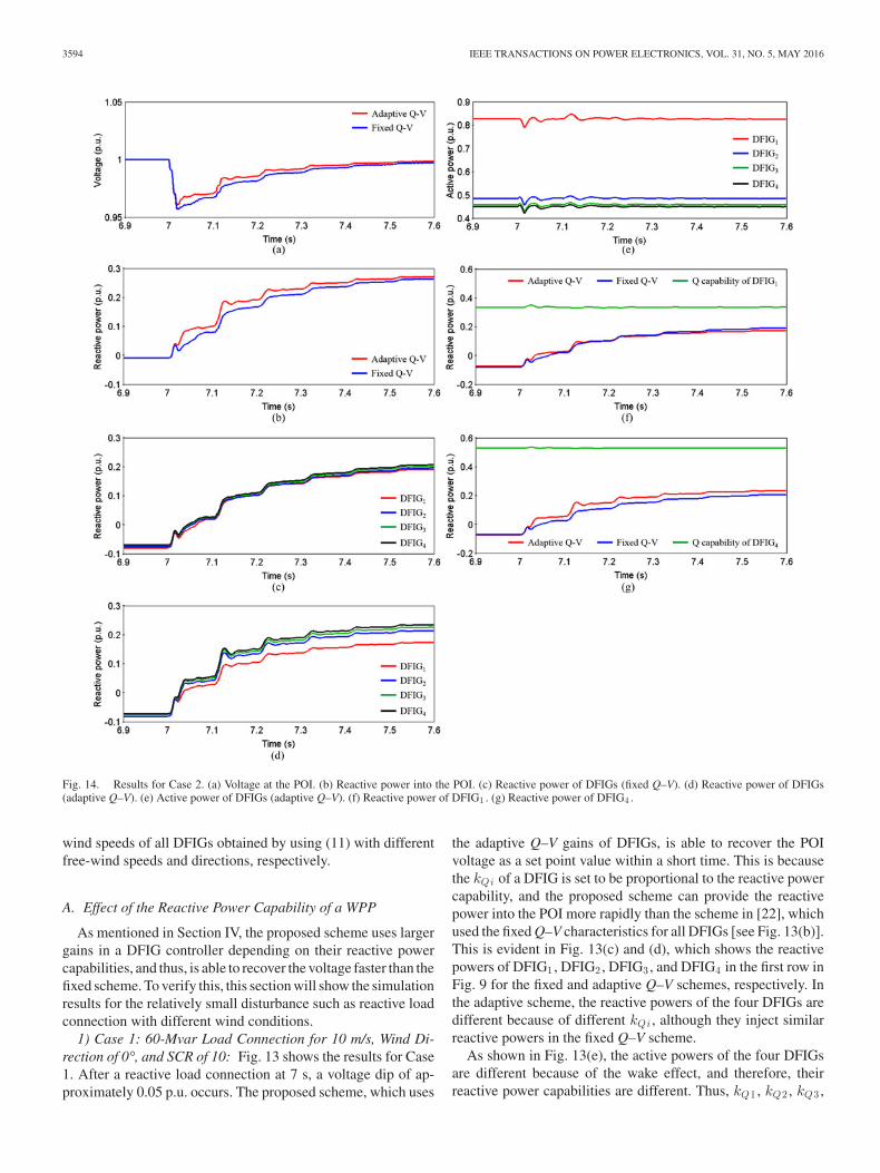
Fig. 14. Results for Case 2. (a) Voltage at the POI. (b) Reactive power into the POI. (c) Reactive power of DFIGs (fixed Q–V). (d) Reactive power of DFIGs(adaptive Q–V). (e) Active power of DFIGs (adaptive Q–V). (f) Reactive power of DFIG1 . (g) Reactive power of DFIG4 .
wind speeds of all DFIGs obtained by using (11) with differentfree-wind speeds and directions, respectively.
A. Effect of the Reactive Power Capability of a WPP
As mentioned in Section IV, the proposed scheme uses largergains in a DFIG controller depending on their reactive powercapabilities, and thus, is able to recover the voltage faster than thefixed scheme. To verify this, this section will show the simulationresults for the relatively small disturbance such as reactive loadconnection with different wind conditions.
1) Case 1: 60-Mvar Load Connection for 10 m/s, Wind Di-rection of 0°, and SCR of 10: Fig. 13 shows the results for Case1. After a reactive load connection at 7 s, a voltage dip of ap-proximately 0.05 p.u. occurs. The proposed scheme, which uses
the adaptive Q–V gains of DFIGs, is able to recover the POIvoltage as a set point value within a short time. This is becausethe kQi of a DFIG is set to be proportional to the reactive powercapability, and the proposed scheme can provide the reactivepower into the POI more rapidly than the scheme in [22], whichused the fixed Q–V characteristics for all DFIGs [see Fig. 13(b)].This is evident in Fig. 13(c) and (d), which shows the reactivepowers of DFIG1 , DFIG2 , DFIG3 , and DFIG4 in the first row inFig. 9 for the fixed and adaptive Q–V schemes, respectively. Inthe adaptive scheme, the reactive powers of the four DFIGs aredifferent because of different kQi , although they inject similarreactive powers in the fixed Q–V scheme.
As shown in Fig. 13(e), the active powers of the four DFIGsare different because of the wake effect, and therefore, theirreactive power capabilities are different. Thus, kQ1 , kQ2 , kQ3 ,

KIM et al.: ADAPTIVE Q–V SCHEME FOR THE VOLTAGE CONTROL OF A DFIG-BASED WIND POWER PLANT 3595
Fig. 15. Results for Case 3. (a) Voltage at the POI. (b) Reactive power into the POI. (c) Reactive power of DFIGs (adaptive Q–V). (d) Active power of DFIGs(adaptive Q–V). (e) Reactive power of DFIG1 . (f) Reactive power of DFIG4 .
and kQ4 of the four DFIGs are initially set to 14.14, 15.72,15.80, and 15.83, respectively, prior to a disturbance, but theywill change with time after a disturbance because of the changein active power [see Fig. 13(f)]. This means that DFIG4 willinject the largest reactive power among them. As shown inFig. 13(g) and (h), in the adaptive scheme, DFIG4 injectsmore reactive power than DFIG1 . In addition, in the adaptivescheme, DFIG4 injects more reactive power and does it fasterthan that of the fixed scheme, whereas in the adaptive schemeDFIG1 injects faster than that of the fixed scheme. This is be-cause kQ4 is larger than kQ1 due to its larger reactive powercapability.
Fig. 13(i) shows the terminal voltages of the four DFIGs andof the POI. The DFIG voltages are the nearly the same before andafter a disturbance. Before a disturbance, the terminal voltagesof the DFIGs are smaller than that of the POI, because theyconsume the reactive power; however, after a disturbance, theyinject the reactive power into the grid to recover the voltage, andtherefore, the terminal voltages of the DFIGs are larger than thePOI voltage but the DFIGs voltages remain at an acceptablelevel.
2) Case 2: 60-Mvar Load Connection for 12 m/s, Wind Direc-tion of 45°, and SCR of 10: Fig. 14 shows the results for Case
2, which is identical to Case 1 except for the wind condition.In this case, the wind speeds of DFIGs are higher than Case 1as shown in Table IV, and thus, the reactive power capability ofthe WPP is smaller than it is in Case 1; therefore, in the adap-tive scheme, the voltage Case 2 recovers slightly slower thanin Case 1. However, the adaptive scheme can recover the POIvoltage within a shorter time than the fixed scheme, as shownin Fig. 14(a), because the adaptive scheme provides reactivepower into the POI more and faster than the fixed scheme [seeFig. 14(b)].
As show in Fig. 14(c) and (d), in the adaptive scheme, the fourDFIGs inject different amounts of reactive power depending ontheir reactive power capabilities, although they supply similarreactive powers in the fixed scheme. This because the activepowers of the four DFIGs are different due to the wake effects[see Fig. 14(e)]. In the adaptive scheme, kQ1 , kQ2 , kQ3 , andkQ4 are set to 10.37, 14.10, 14.32, and 14.40, respectively, priorto a disturbance, which are proportional to their reactive powercapabilities. Note that the gains in Case 2 are smaller than thosein Case 1.
As in Case 1, in the adaptive scheme, DFIG1 injects a simi-lar reactive power to that of the fixed scheme [see Fig. 14(f)],whereas in the adaptive scheme DFIG4 injects more reactive

3596 IEEE TRANSACTIONS ON POWER ELECTRONICS, VOL. 31, NO. 5, MAY 2016
Fig. 16. Results for Case 4. (a) Voltage at the POI. (b) Reactive power into the POI. (c) Reactive power of DFIGs (adaptive Q–V). (d) Active power of DFIGs(adaptive Q–V). (e) Reactive power of DFIG1 . (f) Reactive power of DFIG4 .
power than in the fixed scheme because of the large gain [seeFig. 14(g)].
The results of the above two cases clearly show that theproposed scheme successfully recovers the voltage in the case ofthe reactive load connection more quickly than the fixed schemeby utilizing the available reactive power capabilities in the WPPand shows better performance in weaker wind conditions, whichretains more reactive power capability.
B. Effect of the Grid Stiffness
As mentioned above, the performance of a WPP voltage con-trol scheme is dependent on the grid stiffness. Thus, this sectionwill describe the investigation results for the WPP connected toa weaker grid, which has a smaller SCR of 4.
1) Case 3: 60-Mvar Load Connection for 12 m/s, Wind Di-rection of 45°, and SCR of 4: Fig. 15 shows the results for case3, which is identical to Case 2 except for the smaller SCR of4. This means that the WPP is connected to a weaker grid thanCase 2. In this case, a voltage dip deeper than Case 1 occurs,and therefore, more reactive power is required to recover thePOI voltage. Unlike the previous two cases, the fixed schemeis unable to completely recover the POI voltage to the nominal
value, because the injected reactive power is less than the re-quired value [see Fig. 15(b)]. However, the adaptive scheme canrecover the POI voltage within a short time by utilizing the avail-able reactive power of the WPP. As in the previous cases, dueto the wake effect, the four DFIGs in the first row produce dif-ferent amounts of active power [see Fig. 15(d)]. In the adaptivescheme, the four DFIGs inject the reactive power depending ontheir reactive power capabilities, although they supply similarreactive powers in the fixed scheme; in addition, in this case, theproposed scheme injects more reactive power than that of thefixed scheme, whereas both schemes inject the similar reactivepower in Case 2.
In the adaptive scheme, DFIG1 injects similar reactive powerto that of the fixed scheme, because the wind speed of DFIG1is 12 m/s (rated wind speed), and the fixed scheme could alsoinject the reactive power closer to the maximum reactive powercapability [see Fig. 15(e)]. However, the wind speed of DFIG4is the lowest, and therefore, its reactive power capability is thelargest. The adaptive scheme allows DFIG4 to inject more thanin the fixed scheme [see Fig. 15(f)] exceeding 0.33 p.u., whichis the maximum reactive power capability in the fixed scheme;in this case, the difference between the two schemes is largerthan that of the two schemes in Case 2. Note that the gains kQ1 ,

KIM et al.: ADAPTIVE Q–V SCHEME FOR THE VOLTAGE CONTROL OF A DFIG-BASED WIND POWER PLANT 3597
Fig. 17. Results for Case 5. (a) Voltage at the POI. (b) Reactive power into the POI. (c) Reactive power of DFIGs (adaptive Q–V). (d) Active power of DFIGs(adaptive Q–V). (e) Reactive power of DFIG1 . (f) Reactive power of DFIG4 .
kQ2 , kQ3 , and kQ4 are the same as those in Case 2 because thewind conditions are the same as Case 2.
The results indicate that the proposed adaptive scheme alsosuccessfully recovers the voltage within a short time, even for aweak grid, because it makes use of the available reactive powerwithin a WPP.
C. Effects of a Grid Fault With Different Fault Locations
In the previous Cases, the performance of the scheme wasinvestigated for less severe disturbance such as reactive loadconnection. On the contrary, this section will show the investi-gation results of the proposed scheme for severe disturbancessuch as grid faults with different fault locations.
1) Case 4: 0.6-p.u. Grid Fault for 400 ms With 10 m/s, WindDirection of 0°, SCR of 4, and a = 0.1: Fig. 16 shows theresults for Case 4, where a 0.6-p.u. grid fault occurs at 7 snear the WPP (a = 0.1) and lasts for 400 ms. In this case,more reactive power is required for the voltage support becauseof the grid fault. During the fault period, the adaptive schemeshows the improved POI voltage support with a greater reactivepower injection than the fixed scheme [see Fig. 16(b)]. This isbecause the adaptive scheme injects more reactive power duringthe fault than does the fixed scheme. Note that in this case,
the injected reactive powers from the four DFIGs in the frontrow are fluctuating [see Fig. 16(c)], while increasing during thefault because the active powers are fluctuating [see Fig. 16(d)],and thus, their gains are also fluctuating. However, in the fixedscheme, the reactive powers are fluctuating without increasing.On the other hand, after a fault clearance, the fixed schemeshows a similar performance to the adaptive scheme, althoughthe adaptive scheme supplies slightly more reactive power thanthe fixed scheme.
As expected, in the adaptive scheme, DFIG1 and DFIG4 injectnearly up to the maximum available reactive power. In addition,during the fault period, DFIG4 injects more reactive power thanDFIG1 , because DFIG4 has a larger reactive power capabilitythan DFIG1 . Note that the fixed scheme injects approximately0.33 p.u., which is the maximum reactive power set based onthe rated active power, as shown in Fig. 16(e) and (f).
2) Case 5: 0.6-p.u. Grid Fault for 400 With 10 m/s, WindDirection of 0°, SCR of 4, and a = 0.5: Fig. 17 shows the resultsfor Case 5, which is the same case as Case 4 except for the faultlocation of 0.5. Thus, the POI voltage experiences less voltagedip than in Case 4 due to the larger impedance between the POIand fault location [see Fig. 17(a)]. In this case, the fixed schemecould recover the voltage closer to the rated value than Case4 during the fault period; however, the adaptive scheme shows

3598 IEEE TRANSACTIONS ON POWER ELECTRONICS, VOL. 31, NO. 5, MAY 2016
the improved POI voltage support [see Fig. 17(b)], because theadaptive scheme injects more reactive power during the faultthan does the fixed scheme.
In the adaptive scheme, DFIG1 and DFIG4 effectively utilizethe reactive power proportional to their reactive power capa-bilities as shown in Fig. 17(e) and (f). Hence, during the faultperiod, DFIG4 injects more reactive power than DFIG1 . How-ever, in the fixed scheme, as in Case 4, DFIG1 and DFIG4 injectthe reactive power approximately 0.33-p.u.
The results of Cases 4 and 5 indicate that the adaptive schemesuccessfully support the voltage during the grid fault more thanthe fixed scheme by utilizing the reactive power capability of aWPP; in addition, the adaptive scheme becomes more effectivein the case of a remote fault from the POI.
VI. CONCLUSION
This paper proposes an adaptive Q–V scheme for the voltagecontrol of a DFIG-based WPP to achieve instant voltage recov-ery. In the proposed scheme, both the WPP and DFIG controllersemploy a voltage control mode to recover the POI voltage withina short time after a disturbance. DFIGs will inject the reactivepower based on their adaptive Q–V gains depending on theirreactive power capabilities. In addition, the approaching windspeed of each DFIG in a WPP was obtained by considering thecumulative impact of multiple shadowing and the effect of winddirection.
The test results clearly indicate that the adaptive scheme suc-cessfully recovers the POI voltage within a short time after adisturbance, even for a weak grid with a small SCR by utilizingthe available reactive power capabilities of the DFIGs in theWPP; the adaptive scheme allows a DFIG with a larger reac-tive power capability to inject more reactive power through theadaptive gain setting.
The advantage of the proposed scheme is that the adaptivescheme ensures instant transient voltage recovery by utilizingits available reactive power capability, and therefore it needsless additional reactive power to maintain the voltage of a WPPand regulate a POI voltage in a grid even with a small SCR.
REFERENCES
[1] Global Wind Energy Council, Global Wind Energy Outlook 2014, Oct.2014.
[2] S. Muller, M. Deicke, and R. W. De Doncker, “Doubly fed inductiongenerator systems for wind turbine,” IEEE Trans. Ind. Appl., vol. 8, no. 3,pp. 26–33, May/Jun. 2002.
[3] F. Blaabjerg and Z. Chen, Power Electronics for Modern Wind Turbines,1st ed. Seattle, WA, USA: Morgan & Claypool, 2006.
[4] R. Cardenas, R. Pena, S. Alepuz, and G. Asher, “Overview of controlsystems for the operation of DFIGs in wind energy applications,” IEEETrans. Ind. Electron., vol. 60, no. 7, pp. 2776–2798, Jul. 2013.
[5] F. Blaabjerg and K. Ma, “Future on power electronics for wind turbinesystems,” IEEE J. Emerg. Sel. Topics Power Electron., vol. 1, no. 3,pp. 139–152, Sep. 2013.
[6] H. Polinder, J. A. Ferreira, B. B. Jensen, A. B. Abrahamsen, K. Atallah,and R. A. McMahon, “Trends in wind turbine generator systems,” IEEE J.Emerg. Sel. Topics Power Electron., vol. 1, no. 3, pp. 174–185, Sep. 2013.
[7] Z. Chen, J. M. Guerrero, and F. Blaabjerg, “A review of the state of theart of power electronics for wind turbines,” IEEE Trans. Power Electron.,vol. 24, no. 8, pp. 1859–1875, Aug. 2009.
[8] M. Liserre, R. Cardenas, M. Molinas, and J. Rodriguez, “Overview ofmulti-MW wind turbines and wind parks,” IEEE Trans. Ind. Electron.,vol. 58, no. 4, pp. 1081–1095, Apr. 2011.
[9] Grid Code: High and Extra High Voltage, E. ON Netz GmbH, Bayreuth,Germany, Aug. 2006.
[10] M. Tsili and S. Papathanassiou, “A review of grid code technical re-quirements for wind farms,” IET Renew. Power Gener., vol. 3, no. 3,pp. 308–332, Sep. 2009.
[11] F. K. A. Lima, A. Luna, P. Rodriguez, E. H. Watanabe, and F. Blaabjerg,“Rotor voltage dynamics in the doubly fed induction generator duringgrid faults,” IEEE Trans. Power Electron., vol. 25, no. 1, pp. 118–130,Jan. 2010.
[12] S. Zhang, K. J. Tseng, S. S. Choi, T. D. Nguyen, and D. L. Yao, “Ad-vanced control of series voltage compensation to enhance wind turbineride through,” IEEE Trans. Power Electron., vol. 27, no. 2, pp. 763–772,Feb. 2012.
[13] H. Xu, J. Hu, and Y. He, “Operation of wind-turbine-driven DFIG sys-tems under distorted grid voltage conditions: Analysis and experimentalvalidations,” IEEE Trans. Power Electron., vol. 27, no. 5, pp. 2354–2366,May 2012.
[14] M. Mohseni and S. M. Islam, “Transient control of DFIG-based windpower plants in compliance with the Australian grid code,” IEEE Trans.Power Electron., vol. 27, no. 6, pp. 2813–2824, Jun. 2012.
[15] H. Geng, C. Liu, and G. Yang, “LVRT capability of DFIG-based WECSunder asymmetrical grid fault condition,” IEEE Trans. Ind. Electron.,vol. 60, no. 6, pp. 2495–2509, Jun. 2013.
[16] J. Yao, H. Li, Z. Chen, X. Xia, X. Chen, Q. Li, and Y. Liao, “Enhancedcontrol of a DFIG-based wind-power generation system with series grid-side converter under unbalanced grid voltage conditions,” IEEE Trans.Power Electron., vol. 28, no. 7, pp. 3167–3181, Jul. 2013.
[17] C. Liu, D. Xu, N. Zhu, F. Blaabjerg, and M. Chen, “DC-voltage fluctuationelimination through a DC-capacitor current control for DFIG convertersunder unbalanced grid voltage conditions,” IEEE Trans. Power Electron.,vol. 28, no. 7, pp. 3206–3218, Jul. 2013.
[18] A. Camacho, M. Castilla, J. Miret, R. Guzman, and A. Borrell, “Reactivepower control for distributed generation power plants to comply withvoltage limits during grid faults,” IEEE Trans. Power Electron., vol. 29,no. 11, pp. 6224–6234, Nov. 2014.
[19] A. Tapia, G. Tapia, and J. X. Ostolaza, “Reactive power control of windfarms for voltage control applications,” Renew. Energy, vol. 29, no. 3,pp. 377–392, Mar. 2004.
[20] D. Hansen, P. Sorensen, F. Iov, and F. Blaabjerg, “Centralised power con-trol of wind farm with doubly fed induction generators,” Renew. Energy,vol. 31, no. 7, pp. 935–951, Jun. 2006.
[21] M. E. Moursi, G. Joos, and C. Abbey, “A secondary voltage controlstrategy for transmission level interconnection of wind generation,” IEEETrans. Power Electron., vol. 23, no. 3, pp. 1178–1190, May 2008.
[22] J. Fortmann, M. Wilch, I. Erlich, and F. Koch, “A novel centralised windfarm controller utilising voltage control capability of wind turbines,” inProc. Power Syst. Comput. Conf. 2008, Jul. 2008.
[23] J. Fortmann and I. Erlich, “Use of a deadband in reactive power controlrequirements for wind turbines in European grid code,” presented at the11th Int. Workshop Large-Scale Integr. Wind Power Power Syst., Lisbon,Portugal, Nov. 13–15, 2012.
[24] J. Martı́nez, P. Kjaer, P. Rodriguez, and R. Teodorescu, “Design andanalysis of a slope voltage control for a DFIG wind power plant,” IEEETrans. Energy Convers., vol. 27, no. 1, pp. 11–20, Mar. 2012.
[25] National Grid, The Grid Code-Issue 4, Revision 5,” Dec.31, 2010.[26] B. Boukhezzar and H. Siguerdidjane, “Nonlinear control of a variable-
speed wind turbine using a two-mass model,” IEEE Trans. Energy Con-vers., vol. 26, no. 1, pp. 149–162, Mar. 2011.
[27] A. D. Hansen, P. Sørensen, F. Iov, and F. Blaabjerg, “Control of variablespeed wind turbines with doubly-fed induction generators,” Wind Eng.,vol. 28, no. 4, pp. 411–432, Jun. 2004.
[28] P. Ledesma and J. Usaola, “Doubly fed induction generator model fortransient stability analysis,” IEEE Trans. Energy Convers., vol. 20, no. 2,pp. 388–397, Jun. 2005.
[29] B. Shen, B. Mwinyiwiwa, Y. Zhang, and B. Ooi, “Sensorless maximumpower point tracking of wind by DFIG using rotor position phase lockloop,” IEEE Trans. Power Electron., vol. 24, no. 4, pp. 942–951, Apr.2009.
[30] O. Anaya-Lara, N. Jenkins, J. Ekanayake, P. Cartwright, and M. Hughes,Wind Energy Generation: Modeling and Control. New York, NY, USA:Wiley, 2009.

KIM et al.: ADAPTIVE Q–V SCHEME FOR THE VOLTAGE CONTROL OF A DFIG-BASED WIND POWER PLANT 3599
[31] T. Lund, P. Sorensen, and J. Eek, “Reactive power capability of a windturbine with doubly fed induction generator,” Wind Energy, vol. 10,pp. 379–394, Jun. 2007.
[32] J. Kim, J. Lee, Y. Suh, B. Lee, and Y. Kang, “Fault response of a DFIG-based wind power plant taking into account the wake effect,” J. Electr.Eng. Technol., vol. 9, no. 3, pp. 820–826, May 2014.
[33] N. O. Jensen, “A note on wind generator interaction,” Risø Nat. Lab.,Tech. Rep. RISO-M-2411, Roskilde, Denmark Nov. 1983.
[34] F. Koch, M. Gresch, F. Shewarega, I. Erlich, and U. Bachmann, “Consid-eration of wind farm wake effect in power system dynamic simulation,”presented at the Power Tech Conf., St. Petersburg, Russia, Jun. 27–30,2005.
[35] I. Katic, J. Højstrup, and N. O. Jensen, “A simple model for clusterefficiency,” presented at the Eur. Wind Energy Assoc. Conf. Exhib., Rome,Italy, 1986.
[36] J. Martı́nez, P. C. Kjer, and R. Teodorescu, “DFIG turbine representationfor small signal voltage control studies,” in Proc. Optim. Electr. Electron.Equip., May 2010, pp. 31–40.
Jinho Kim (S’14) received the B.S. and M.S. degreesfrom Chonbuk National University, Jeonju, Korea, in2013 and 2015, respectively, where he is currentlyworking toward the Ph.D. degree.
He is an Assistant Researcher at the Wind En-ergy Grid-Adaptive Technologies Research Center,Jeonju, supported by the Ministry of Science, ICT andFuture Planning, Korea. His research interests includethe development of hardware-in-the-loop simulation-based control strategies and integrated test bed forwind power plants.
Jul-Ki Seok (S’94–M’98–SM’09) received the B.S.,M.S., and Ph.D. degrees from Seoul National Univer-sity, Seoul, Korea, in 1992, 1994, and 1998, respec-tively, all in electrical engineering.
From 1998 to 2001, he was a Senior Engineerwith the Production Engineering Center, SamsungElectronics, Suwon, Korea. Since 2001, he has beena Member of the Faculty at the School of Electri-cal Engineering, Yeungnam University, Gyeongsan,Korea, where he is currently a Professor. His currentresearch interests include motor drives, power con-
verter control of offshore wind farms, and nonlinear system identification relatedto the power electronics field.
Dr. Seok is currently a Member of the Editorial Board of the Institution ofEngineering and Technology Electric Power Applications.
Eduard Muljadi (M’82–SM’94–F’10) received thePh.D. degree in electrical engineering from the Uni-versity of Wisconsin, Madison, WI, USA.
From 1988 to 1992, he was with California StateUniversity at Fresno. In June 1992, he joined the Na-tional Renewable Energy Laboratory, Golden, CO,USA. His current research interests include electricmachines, power electronics, and grids in general,with an emphasis on renewable energy applications.
Dr. Muljadi is a Member of the Eta Kappa Nu andthe Sigma Xi, and an Editor of the IEEE TRANSAC-
TIONS ON ENERGY CONVERSION. He is involved in the activities of the IEEE In-dustry Application Society (IAS), the Power Electronics Society, and the Powerand Energy Society (PES). He is currently a Member of various committees ofthe IAS, and a Member of the Working Group on Renewable Technologies andthe Task Force on Dynamic Performance of Wind Power Generation, both ofthe PES.
Yong Cheol Kang (S’92–M’99–SM’13) received theB.S., M.S., and Ph.D. degrees from Seoul NationalUniversity, Seoul, Korea, in 1991, 1993, and 1997,respectively.
Since 1999, he has been with Chonbuk NationalUniversity, Jeonju, Korea, where he is currently aProfessor and Director at the Wind energy Grid-Adaptive Technologies Research Center supportedby the MSIP, Korea. His research interest includesthe development of new protection and control sys-tems for wind power plants.
Dr. Kang is currently a Member of the International Electrotechnical Com-mission 61400-27 working group.