Adaptive Notch Filter for EEG Signals Based on the LMS ...€¦ · Hz), theta (4-7 Hz), alpha (7-13...
6
2005 Conference on Information Sciences and Systems, The Johns Hopkins University, March 16–18, 2005 Adaptive Notch Filter for EEG Signals Based on the LMS Algorithm with Variable Step-Size Parameter Daniel Olgu´ ın Olgu´ ın 1 e-mail: [email protected] Frantz Bouchereau 1 e-mail: [email protected] Sergio Mart´ ınez 1 e-mail: [email protected] Abstract — This paper presents the use of an adaptive noise canceler (ANC) with variable step-size parameter for the elimination of power line interference in the recording of EEG signals within the relatively unex- plored gamma-band (35- 100 Hz). The use of an adap- tive step-size parameter offers a balance in terms of convergence, misadjustment, and rejection bandwidth optimization. Simulation results are presented to sup- port the proposed algorithm and compare its perfor- mance with fixed step-size ANC schemes. It will be shown that the proposed algorithm outperforms clas- sical fixed step-size ANC algorithms and eliminates the cumbersome trial and error process needed to choose an adequate value for such parameter. I. Introduction The elimination of the interference caused by power trans- mission lines in the recording of physiological signals of elec- trical nature has been an active topic of research for the last few decades [1], [2], [3]. The majority of electrophysiological recordings unavoidably contain an undesired level of interfer- ence deriving from the power transmission lines. Moreover, the line-frequency contamination is not of constant amplitude, phase, or even frequency [1]. Such variability prevents a sim- ple subtractive filter from being completely effective. A fixed notch filter may eliminate the noise when its distri- bution is centered exactly at the frequency for which the filter was designed [2]. However, the frequency of the power-line noise is not constant at exactly 60 Hz. The importance of the work presented in this paper relies on the fact that there is existence of epileptiform oscillations with frequencies nearby the power line interference frequency which have been ignored because of the lack of an effective notch filter capable of elim- inating the noise components without affecting the original electroencephalographic (EEG) signal. Worrell et al. [4] have found that currently available clinical EEG systems and EEG analysis methods utilize a dynamic range (0.1-30 Hz) that discards clinically important information. Their results show that the dynamic range utilized in current clinical practice largely ignores fundamental oscillations that are signatures of an epileptogenic brain. A finer study of high-frequency EEG oscillations may open a new possibility for patients who are poor candidates to epilepsy surgery, allowing seizure predic- tion and epilepsy treatment through several therapeutic meth- ods. The results presented in [4] suggest the need to design a notch filter with an optimal rejection bandwidth that effec- tively eliminates the time-varying noise introduced by power 1 All three authors are with the Department of Electrical Engi- neering, Tecnol´ ogico de Monterrey, Campus Monterrey, Mexico. The authors acknowledge the finantial support provided by the Consejo de Ciencia y Tecnolog´ ıa del Estado de Nuevo Le´ on (CO- CYTENL). transmission lines. The proposed filter should have an opti- mum speed of convergence and allow the minimization of loss of information and distortion of the signal of interest. Power line interference recorded in EEG generally results from poor electrode application on the scalp. This noise is often due to high-impedance electrodes that, when connected to the recording device, affect the common mode rejection ra- tio of the amplifier, which changes when the impedances of electrodes and scalp are not matched. Ensuring impedance measurements of less than 5 kΩ will usually reduce such line- frequency noise [5]. The standard practice now is to measure all potentials relative to a common electrode which is isolated from ground. This improves subject safety and reduces power line noise. However, taking all the existing measures to min- imize the interference is not enough when we are interested in measuring signals with frequency components that are very close to those of the interference, and with amplitudes which are one or more orders of magnitude smaller than the noise. There have been several attempts of eliminating power line interference by using digital signal processing tech- niques [2], [3]. In applications where the information of in- terest is contained within the classical EEG bands: delta (0-4 Hz), theta (4-7 Hz), alpha (7-13 Hz) and beta (13-35 Hz); it is of common practice to use a 60/50 Hz notch filter with a fixed null in its frequency response characteristic to remove the noise from the data. Sometimes the EEG signal is further low-pass filtered with a cut-off frequency of less than 50 Hz to assure the integrity of the data. In [2], three different adap- tive notch filters are considered: an FIR second-order filter, a second-order IIR filter with fixed zeros and varying poles, and a second-order IIR filter with varying zeros and poles. The three filters were designed using a constrained LMS algorithm with fixed step-size. It was observed that only the non-fixed pole-zero IIR filter was able to track the frequency variation with a variable bandwidth. However, a difficult design issue that arised from this filtering scheme was that of choosing an adequate step-size parameter to adjust the filter’s coefficients and obtain optimal convergence, tracking and rejection band- width conditions. In this paper, we propose an adaptive notch filter to elim- inate the interference introduced by power transmission lines in the recording of EEG signals within the gamma-band (35- 100 Hz), based on an adaptive noise canceling scheme imple- mented with a variable step-size LMS algorithm. The pro- posed algorithm avoids the cumbersome trial and error pro- cess needed to choose an adequate value for the step-size pa- rameter and will minimize the rejection bandwidth required to effectively eliminate the time-varying interference while, at the same time, preserving optimal convergence, tracking and misadjustment conditions. Numerical results will be presented to compare the algo- rithm with the classical fixed step-size adaptive noise cancel- ing scheme. We will consider the case where the frequency of
Transcript of Adaptive Notch Filter for EEG Signals Based on the LMS ...€¦ · Hz), theta (4-7 Hz), alpha (7-13...
2005 Conference on Information Sciences and Systems, The Johns Hopkins University, March 16–18, 2005
Adaptive Notch Filter for EEG Signals Based on the LMS Algorithmwith Variable Step-Size Parameter
Daniel Olguın Olguın 1
e-mail: [email protected]
Frantz Bouchereau 1
e-mail: [email protected]
Sergio Martınez 1
e-mail: [email protected]
Abstract —This paper presents the use of an adaptive noise
canceler (ANC) with variable step-size parameterfor the elimination of power line interference in therecording of EEG signals within the relatively unex-plored gamma-band (35- 100 Hz). The use of an adap-tive step-size parameter offers a balance in terms ofconvergence, misadjustment, and rejection bandwidthoptimization. Simulation results are presented to sup-port the proposed algorithm and compare its perfor-mance with fixed step-size ANC schemes. It will beshown that the proposed algorithm outperforms clas-sical fixed step-size ANC algorithms and eliminatesthe cumbersome trial and error process needed tochoose an adequate value for such parameter.
I. Introduction
The elimination of the interference caused by power trans-mission lines in the recording of physiological signals of elec-trical nature has been an active topic of research for the lastfew decades [1], [2], [3]. The majority of electrophysiologicalrecordings unavoidably contain an undesired level of interfer-ence deriving from the power transmission lines. Moreover,the line-frequency contamination is not of constant amplitude,phase, or even frequency [1]. Such variability prevents a sim-ple subtractive filter from being completely effective.
A fixed notch filter may eliminate the noise when its distri-bution is centered exactly at the frequency for which the filterwas designed [2]. However, the frequency of the power-linenoise is not constant at exactly 60 Hz. The importance of thework presented in this paper relies on the fact that there isexistence of epileptiform oscillations with frequencies nearbythe power line interference frequency which have been ignoredbecause of the lack of an effective notch filter capable of elim-inating the noise components without affecting the originalelectroencephalographic (EEG) signal. Worrell et al. [4] havefound that currently available clinical EEG systems and EEGanalysis methods utilize a dynamic range (0.1-30 Hz) thatdiscards clinically important information. Their results showthat the dynamic range utilized in current clinical practicelargely ignores fundamental oscillations that are signatures ofan epileptogenic brain. A finer study of high-frequency EEGoscillations may open a new possibility for patients who arepoor candidates to epilepsy surgery, allowing seizure predic-tion and epilepsy treatment through several therapeutic meth-ods. The results presented in [4] suggest the need to designa notch filter with an optimal rejection bandwidth that effec-tively eliminates the time-varying noise introduced by power
1All three authors are with the Department of Electrical Engi-neering, Tecnologico de Monterrey, Campus Monterrey, Mexico.The authors acknowledge the finantial support provided by theConsejo de Ciencia y Tecnologıa del Estado de Nuevo Leon (CO-CYTENL).
transmission lines. The proposed filter should have an opti-mum speed of convergence and allow the minimization of lossof information and distortion of the signal of interest.
Power line interference recorded in EEG generally resultsfrom poor electrode application on the scalp. This noise isoften due to high-impedance electrodes that, when connectedto the recording device, affect the common mode rejection ra-tio of the amplifier, which changes when the impedances ofelectrodes and scalp are not matched. Ensuring impedancemeasurements of less than 5 kΩ will usually reduce such line-frequency noise [5]. The standard practice now is to measureall potentials relative to a common electrode which is isolatedfrom ground. This improves subject safety and reduces powerline noise. However, taking all the existing measures to min-imize the interference is not enough when we are interestedin measuring signals with frequency components that are veryclose to those of the interference, and with amplitudes whichare one or more orders of magnitude smaller than the noise.
There have been several attempts of eliminating powerline interference by using digital signal processing tech-niques [2], [3]. In applications where the information of in-terest is contained within the classical EEG bands: delta (0-4Hz), theta (4-7 Hz), alpha (7-13 Hz) and beta (13-35 Hz); itis of common practice to use a 60/50 Hz notch filter with afixed null in its frequency response characteristic to removethe noise from the data. Sometimes the EEG signal is furtherlow-pass filtered with a cut-off frequency of less than 50 Hz toassure the integrity of the data. In [2], three different adap-tive notch filters are considered: an FIR second-order filter, asecond-order IIR filter with fixed zeros and varying poles, anda second-order IIR filter with varying zeros and poles. Thethree filters were designed using a constrained LMS algorithmwith fixed step-size. It was observed that only the non-fixedpole-zero IIR filter was able to track the frequency variationwith a variable bandwidth. However, a difficult design issuethat arised from this filtering scheme was that of choosing anadequate step-size parameter to adjust the filter’s coefficientsand obtain optimal convergence, tracking and rejection band-width conditions.
In this paper, we propose an adaptive notch filter to elim-inate the interference introduced by power transmission linesin the recording of EEG signals within the gamma-band (35-100 Hz), based on an adaptive noise canceling scheme imple-mented with a variable step-size LMS algorithm. The pro-posed algorithm avoids the cumbersome trial and error pro-cess needed to choose an adequate value for the step-size pa-rameter and will minimize the rejection bandwidth requiredto effectively eliminate the time-varying interference while, atthe same time, preserving optimal convergence, tracking andmisadjustment conditions.
Numerical results will be presented to compare the algo-rithm with the classical fixed step-size adaptive noise cancel-ing scheme. We will consider the case where the frequency of

the noise is varying around the nominal frequency of 60 Hz,following a first-order Gauss-Markov process model.
The paper is organized as follows. Section II describes themodel utilized for the EEG and time-varying interference sig-nals. The classical adaptive noise canceler (ANC) is intro-duced in Section III where the proposed algorithm for thestep-size parameter adaptation is also presented. Section IVpresents simulation results. Here, several comparisons be-tween the fixed step-size ANC and our proposed algorithmare presented. Finally, Section V presents conclusions.
II. Signal Model
The signal observation model is given by
x(n) = s(n) + p(n) , (1)
where s(n) is the EEG signal of interest and p(n) is an additivetime-varying sinusoidal interference.
Several mathematical models have been developed to de-scribe EEG signals. Some examples include AR models,matching pursuit method-based models, Kalman filters, andMarkov processes. Since the EEG signal is highly non-stationary its statistical properties are difficult to model ac-curately. In this paper we use a Markov process amplitudemodel originally developed by Nakamura et al. [6]. The artifi-cially generated EEG signal is formed by a linear combinationof K different oscillations xk (k = 1, 2, ..., K) as given by
s(n) =K∑
k=1
ak(n)xk(n) =K∑
k=1
ak(n) sin(2πmkn+ φk) , (2)
where ak(n) is the model’s amplitude obtained from a first-order Gauss-Markov process, mk is the dominant k-th fre-quency, and φk is the initial phase. The (n + 1)-th value ofthe model’s amplitude is defined as
ak(n+ 1) = γkak(n) + ξk(n) , (3)
where ξk(n) is a random increment of Gaussian distributionwith zero mean and variance σ2
ξ,k, and γk is the coefficient ofthe first-order Markov process which must satisfy the condi-tion 0 < γk < 1 for stability.
The power line noise interference is a frequency-varying si-nusoidal with a center frequency of 60 Hz. In this work thisinterference will be modeled as
p(n) = A cos2π[f0 + fv(n)]n+ ψ . (4)
Here, A is assumed to be a constant and deterministic ampli-tude, f0 is the central frequency with a value of 60 Hz, theinitial phase ψ is a random variable uniformly distributed over[0, 2π], and fv(n) is a slowly varying random frequency whichis assumed to be a steady state realization of a zero-meanGauss-Markov process given by
fv(∆k+1) = ρfv(∆k) + η(∆k) , (5)
where ∆k is the time interval index for the process whichmight be larger than the signal sampling interval T , ρ is thecoefficient of the first-order Markov process, and η(∆k) is arandom increment of Gaussian distribution with zero meanand variance σ2
η.
III. Adaptive Noise Canceling System withVariable Step-Size Parameter
The transfer function for a 2nd-order FIR notch filter isgiven by
H(z) = 1 − 2 cos(2πf0)z−1 + z−2 , (6)
with a null at frequency f0. The problem with this filter isthat the notch has a relatively large bandwidth, which meansthat other frequency components around the desired null areseverely attenuated [7]. To improve the frequency character-istics of the filter we may consider a 2nd-order IIR notch filterwith transfer function
H(z) =1 − 2 cos(2πf0)z
−1 + z−2
1 − 2ζ cos(2πf0)z−1 + ζ2z−2, (7)
where ζ is a constant that defines the location of the poles inthe unit circle.
A very narrow notch is usually desired in order to filter outa sinusoidal interference without distorting the original sig-nal. However, if the interference is not precisely known, andif the notch is very narrow, the center of the notch may notfall exactly over the interference. When a reference for theinterference is available, the adaptive noise canceling methodoriginally proposed in [8] may be used. In this method, theinterference is adaptively filtered to match the interfering sinu-soid as closely as possible, allowing them to then be subtractedout. The system is shown in Figure 1.
Figure 1: Adaptive noise canceling system.
Applying this scheme to the problem of filtering a noisyEEG signal, the primary input x(n) of the system corre-sponds to the clean EEG signal s(n) corrupted by power linenoise p(n). These signals are assumed to be uncorrelated,Es(n)p(k) = 0, ∀(n, k). The reference input r(n) is a sinu-soidal signal with frequency fr and zero phase. The value offr is set to the noise interference center frequency f0. Thisreference signal given by r(n) = C cos(2πfrn), is applied toan M -stage tapped delay line. Here C is a constant deter-ministic amplitude usually different from A (the interferenceamplitude). The values at the M taps at time n form thereference M -vector r(n) = [r(n) r(n − 1) ... r(n −M + 1)]T .The output of the filter y(n) is estimated to match the noisep(n) in the primary input. The noise and the reference signalsare assumed to be correlated, Ep(n)r(k) 6= 0.
If we define the M -dimensional filter coefficient vector asw(n) = [w0(n) w1(n) ... wM−1(n)]T , then the equations thatdescribe the adaptation of the system based on the LMS al-gorithm with fixed step-size are given by
y(n) = wT (n)r(n) , (8)
e(n) = d(n) − y(n) , (9)
w(n+ 1) = w(n) + µe(n)r(n) . (10)

Let d(n) denote the desired signal, which in this case isequivalent to the primary input x(n). The error signal e(n) isdefined as the difference between the desired signal d(n) andthe filter’s output signal y(n) = p(n), then
e(n) = x(n) − y(n) ,e(n) = s(n) + p(n) − p(n) ,e(n) = s(n) .
(11)
Clearly s(n) is an estimate of the noise-free EEG signal andthe LMS algorithm is designed to minimize an instantaneousversion of the mean square error (MSE) given by E|e(n)|2 =E|s(n)|2.
It is well known that the ANC transfer function from d(n)to e(n),is given by [8]
H(z) =1 − 2cos (2πfr) z
−1 + z−2
1 − 2(1 − MµC2
4
)cos(2πfr)z−1 +
(1 − MµC2
2
)z−2
,
(12)By comparing equations (12) and (7), we observe that
ζ2 = 1 − MµC2
2+
(MµC2
4
)2
. (13)
If µ is small enough, this can be approximated to ζ2 = 1 −MµC2
2. Then, it is clear that (12) is the transfer function of
a 2nd-order digital IIR notch filter with a null centered atthe reference frequency fr. It can be shown that the 3-dBbandwidth of the null is given by
BW3dB =MµC2
4πT(Hz) . (14)
It is clear from equations (12) and (14) that the position of thefilter poles and the notch bandwidth are directly affected bythe step-size parameter µ. The pole locations become closerto the unit circle and the rejection bandwidth becomes smalleras µ decreases. Hence, the choice of the step-size parameter inthe ANC algorithm represents a tradeoff between misadjust-ment, speed of convergence, tracking, notch attenuation andrejection bandwidth. For the application of interest it is de-sired to have the smallest notch bandwidth, however, it is notpossible to minimize this bandwidth by making µ arbitrarilysmall. Instead, to ensure an optimal equilibrium between allthe desired filter characteristics it becomes necessary to finda method to chose the step-size parameter in an optimal wayat every iteration of the algorithm.
Several variable step-size parameter algorithms have beenproposed in the literature [9], [10]. In [10] the recursion toobtain µ(n) is based on an estimator of ∂e(n)/∂µ(n), however,the complexity of the algorithm and its requirement of theindependence condition Er(n)r(k) = 0, ∀n, k makes it notsuitable for our application.
The objective is to ensure large µ(n) when the algorithmis far from the optimum, and decreasing µ(n) as we approachthe optimum hence decreasing the notch bandwidth and in-creasing noise attenuation. The step-size adjustment proposedin [9] is controlled by the square of the prediction error. Thesimplicity of the algorithm and its sensibility to changes in theerror signal allowed us to implement it in the ANC scheme.The algorithm for updating µ(n) is as follows
µ(n+ 1) = αµ(n) + γe2(n) . (15)
The constant α is a forgetting factor with values between0 < α < 1 and γ > 0 is the step-size parameter for theadaptation of µ. Substituting the variable step-size µ(n) in(10) the update equation for the filter coefficients becomes
w(n+ 1) = w(n) + µ(n)e(n)r(n) . (16)
The initial step-size µ(0) is usually set to µmax and this max-imum value is chosen to ensure stability of the algorithm.
IV. Simulation Results
We applied the algorithm described by equations (8), (9),(15) and (16) to artificially generated EEG signals corruptedwith time-varying power line noise and evaluated its effec-tiveness by analyzing the rate of convergence, misadjustment,rejection bandwidth and tracking capabilities.
Figure 2 shows the power spectral density (PSD) of theEEG signal generated by using the Markov process amplitudemodel described in Section II with K = 2 dominant frequen-cies located at 3 Hz and 12.5 Hz, corresponding to an EEGrecording during baseline. To create the frequency peaks weselected γ1 = 0.98, γ2 = 0.99, and σξ,1 = σξ,2 = 0.01.
0 10 20 30 40 50 60 70 80 90 100−60
−55
−50
−45
−40
−35
−30
−25
−20PSD of artificially generated EEG signal s(n)
Frequency (Hz)
dB
Figure 2: PSD of EEG signal generated by using a Markov processamplitude model with dominant frequencies at 3 Hz and 12.5 Hz.
Let us present four experiments to compare the perfor-mance of the fixed step-size ANC algorithm and the varyingstep-size ANC algorithm. The sampling frequency used alongthe experiments was set to fs = 400 Hz and the number offilter coefficients was set to M = 8.
Let s(i) and s(i) be N -dimensional vectors of the noise-freeand estimated signal at the i-th experiment realization. Then,the ensemble average MSE presented in the following resultsis obtained as
MSE =1
Q
Q∑
i=1
|s(i) − s(i)|2 . (17)
For the experiments presented in this section, N = 16384samples and Q = 200 trials of the experiment. Note that thisMSE is with respect to the noise free and estimated signalwhich is different to the MSE defined in Section III for theoutput error e(n).
Experiment 1
The amplitude of the generated signal s(n) was normalizedto [−1, 1] and a power line noise signal p(n) with amplitude
40 45 50 55 60 65 70 75 80−60
−55
−50
−45
−40
−35
−30
−25
−20PSD of x(n) in the gamma−band
Frequency (Hz)
dB
40 45 50 55 60 65 70 75 80−60
−55
−50
−45
−40
−35
−30
−25
−20PSD of s(n) in the gamma−band
Frequency (Hz)
dB
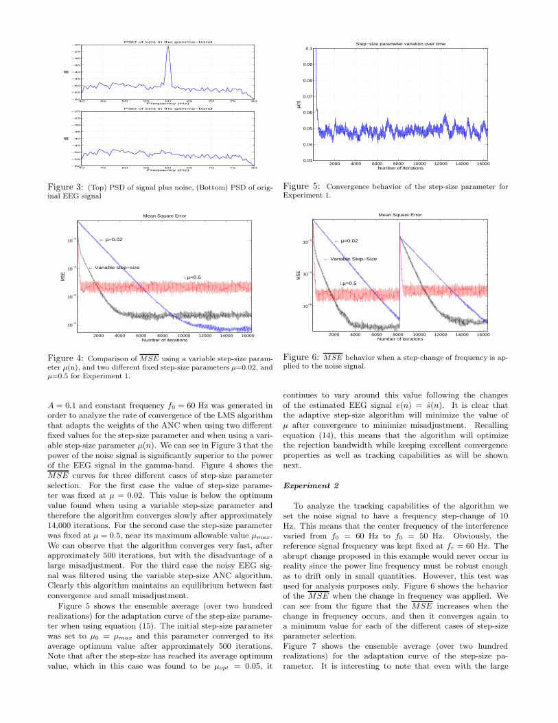
Figure 3: (Top) PSD of signal plus noise, (Bottom) PSD of orig-inal EEG signal
2000 4000 6000 8000 10000 12000 14000 16000
10−6
10−5
10−4
10−3
← Variable step−size
← µ=0.02
↓µ=0.5
Mean Square Error
Number of iterations
MSE
Figure 4: Comparison of MSE using a variable step-size param-eter µ(n), and two different fixed step-size parameters µ=0.02, andµ=0.5 for Experiment 1.
A = 0.1 and constant frequency f0 = 60 Hz was generated inorder to analyze the rate of convergence of the LMS algorithmthat adapts the weights of the ANC when using two differentfixed values for the step-size parameter and when using a vari-able step-size parameter µ(n). We can see in Figure 3 that thepower of the noise signal is significantly superior to the powerof the EEG signal in the gamma-band. Figure 4 shows theMSE curves for three different cases of step-size parameterselection. For the first case the value of step-size parame-ter was fixed at µ = 0.02. This value is below the optimumvalue found when using a variable step-size parameter andtherefore the algorithm converges slowly after approximately14,000 iterations. For the second case the step-size parameterwas fixed at µ = 0.5, near its maximum allowable value µmax.We can observe that the algorithm converges very fast, afterapproximately 500 iterations, but with the disadvantage of alarge misadjustment. For the third case the noisy EEG sig-nal was filtered using the variable step-size ANC algorithm.Clearly this algorithm maintains an equilibrium between fastconvergence and small misadjustment.
Figure 5 shows the ensemble average (over two hundredrealizations) for the adaptation curve of the step-size parame-ter when using equation (15). The initial step-size parameterwas set to µ0 = µmax and this parameter converged to itsaverage optimum value after approximately 500 iterations.Note that after the step-size has reached its average optimumvalue, which in this case was found to be µopt = 0.05, it
2000 4000 6000 8000 10000 12000 14000 160000.03
0.04
0.05
0.06
0.07
0.08
0.09
0.1Step−size parameter variation over time
Number of iterations
µ(n)
Figure 5: Convergence behavior of the step-size parameter forExperiment 1.
2000 4000 6000 8000 10000 12000 14000 16000
10−5
10−4
10−3
← Variable Step−Size
← µ=0.02
↓µ=0.5
Mean Square Error
Number of iterations
MSE
Figure 6: MSE behavior when a step-change of frequency is ap-plied to the noise signal.
continues to vary around this value following the changesof the estimated EEG signal e(n) = s(n). It is clear thatthe adaptive step-size algorithm will minimize the value ofµ after convergence to minimize misadjustment. Recallingequation (14), this means that the algorithm will optimizethe rejection bandwidth while keeping excellent convergenceproperties as well as tracking capabilities as will be shownnext.
Experiment 2
To analyze the tracking capabilities of the algorithm weset the noise signal to have a frequency step-change of 10Hz. This means that the center frequency of the interferencevaried from f0 = 60 Hz to f0 = 50 Hz. Obviously, thereference signal frequency was kept fixed at fr = 60 Hz. Theabrupt change proposed in this example would never occur inreality since the power line frequency must be robust enoughas to drift only in small quantities. However, this test wasused for analysis purposes only. Figure 6 shows the behaviorof the MSE when the change in frequency was applied. Wecan see from the figure that the MSE increases when thechange in frequency occurs, and then it converges again toa minimum value for each of the different cases of step-sizeparameter selection.Figure 7 shows the ensemble average (over two hundredrealizations) for the adaptation curve of the step-size pa-rameter. It is interesting to note that even with the large

2000 4000 6000 8000 10000 12000 14000 160000.03
0.04
0.05
0.06
0.07
0.08
0.09
0.1Step−size parameter variation over time
Number of iterations
µ(n)
Figure 7: Convergence behavior of the step-size parameter forExperiment 2.
0
10
20
30
40
5055606570
0
2
4
6
Time (sec)
Time−frequency variation of noise power spectral density
Frequency (Hz)
PSD
Figure 8: Time-frequency magnitude plot of the noise PSD forExperiment 3.
frequency step-change, the step-size values did not changeconsiderably. This means that the rejection bandwidth ofthe filter remains fairly constant even in the presence oflarge unstationarities. We can conclude once more thatthe variable step-size algorithm minimizes the MSE whilepreserving good tracking capabilities, optimal step-size valuesand small rejection bandwidths.
Experiment 3
Finally we consider the case when the power line frequencyis constantly varying around its nominal value f0 = 60 Hz,following the Gauss-Markov model described in Section II.We defined ∆k = 2 seconds, ρ = 0.99, and ση = 0.1 andgenerated a power line noise signal whose frequency variationwith time is shown in Figure 8. Figure 9 shows the MSEfor the three different cases of step-size parameter selection.We can readily identify the instants in which the noise driftedin frequency. It is important to notice that in all cases thefilters were able to track the frequency changes. However, thevariable step-size algorithm was able to track the frequencychanges while maintaining a fast convergence rate, a smallmisadjustment and an optimum step-size value and hence aminimum rejection bandwidth.
Figure 10 shows the PSD of the signal estimate s(n) forthe three different selections of step-size parameter consideredin this experiment. By comparing these plots with the PSDof the original EEG signal we can see that when the step-size
2000 4000 6000 8000 10000 12000 14000 16000
10−6
10−5
10−4
10−3
← Variable Step−Size
← µ=0.02
↓µ=0.5
Mean Square Error
Number of iterations
MSE
Figure 9: MSE behavior when the noise frequency is varyingevery 2 seconds.
40 45 50 55 60 65 70 75 80−70
−65
−60
−55
−50
−45
−40
−35
−30PSD of s(n) in the gamma−band
Frequency (Hz)
dB
40 45 50 55 60 65 70 75 80−70
−65
−60
−55
−50
−45
−40
−35
−30PSD of estimate of s(n) in the gamma−band when using variable µ
Frequency (Hz)
dB
40 45 50 55 60 65 70 75 80−70
−65
−60
−55
−50
−45
−40
−35
−30PSD of estimate of s(n) in the gamma−band when using µ=0.02
Frequency (Hz)
dB
40 45 50 55 60 65 70 75 80−70
−65
−60
−55
−50
−45
−40
−35
−30PSD of estimate of s(n) in the gamma−band when using µ=0.5
Frequency (Hz)
dB
Figure 10: Comparison of power spectrum in the gamma-band ofthe noise free signal and its estimates. (Top) Spectrum of noise freesignal s(n). (Second) s(n) obtained with adaptive µ, (Third) s(n)obtained with µ=0.02, and (Bottom) s(n) obtained with µ=0.5.

20.5 20.6 20.7 20.8 20.9 21 21.1 21.2 21.3 21.4
−0.1
−0.05
0
0.05
0.1
0.15Original EEG signal + noise in the gamma−band
Time (sec)
x(n)
20.5 20.6 20.7 20.8 20.9 21 21.1 21.2 21.3 21.4
−0.1
−0.05
0
0.05
0.1
0.15Original EEG signal in the gamma−band
Time (sec)
s(n)
20.5 20.6 20.7 20.8 20.9 21 21.1 21.2 21.3 21.4
−0.1
−0.05
0
0.05
0.1
0.15Signal estimate when using variable step−size
Time (sec)
Estima
te of s(n
)
Figure 11: Gamma-band signals: (Top) Signal plus interference,(Center) Original EEG signal s(n), (Bottom) Estimated signal s(n)using the variable step-size parameter algorithm.
2000 4000 6000 8000 10000 12000 14000 16000
10−4
10−3
← Variable step−size↓ µ=0.02
↑µ=0.5
Mean Square Error
Number of iterations
MS
E
Figure 12: MSE behavior in the presence of a periodic non-sinusoidal noise signal.
parameter is adequately chosen, there is no distortion ofthe spectral content in the filtered signal. This is truefor the varying step-size parameter as well as for the casewhen it was kept constant with µ = 0.02. On the otherhand, when the step-size was set to µ = 0.5 the rejectionbandwidth of the filter became too large and the distortionof the spectral content became apparent. One can clearlyobserve a null attenuating several frequencies around 60 Hzfor this scenario. Figure 11 shows the EEG signal plus noisein the gamma-band (40-80 Hz), the original noise-free EEGsignal, and the signal estimate s(n) obtained with the varyingstep-size parameter algorithm. We can appreciate that theoriginal signal is completely masked by the noise signal, andhow well it is reconstructed by the ANC system with varyingstep-size parameter proposed in this paper.
Experiment 4
In this experiment we analyze the effects of periodic non-sinusoidal noise on the ANC algorithm. Figure 12 shows the
MSE when the interference was set to be a sinusoidal trun-cated at values of ±50% of its peak value. It is clear thatalthough the convergence time of the algorithm increased, itwas still able to eliminate the interference using a sinusoidalreference. This result is relevant in cases where amplifier sat-uration may occur and in cases where the signal is windowedin time.
V. ConclusionsWhen dealing with EEG signals in the gamma-band (35-
100 Hz), it is desirable to have a notch filter with a small re-jection bandwidth that effectively eliminates the time-varyingnoise introduced by power transmission lines. The proposedANC system based on a variable step-size LMS algorithm isable to find an optimum speed of convergence which is of greatimportance in real-time applications and allows the minimiza-tion of information loss and signal distortion by keeping thenotch bandwidth as small as possible. The proposed filterscould be implemented in existing EEG recording devices or innew devices intended for real-time ambulatory EEG monitor-ing.
The choice of the step-size parameter in the adaptation al-gorithm plays an important role in the rate of convergence,stability, tracking capabilities and rejection bandwidth of thefilters. The proposed variable step-size method may overcomethe cumbersome trial and error process needed to choose anadequate value for such parameter and will minimize the re-jection bandwidth required to effectively eliminate the time-varying interference introduced by power transmission lines.This last property is of great importance since, as mentionedin the introductory paragraphs, valuable signal information isfound around the interference frequency band.
References[1] K. J. Eriksen “Non-Distorting Post-Acquisition Line-Frequency
for Evoked Potentials, Proceedings of the IEEE EMBS 10thAnnual International Conference, p. 1168, 1988.
[2] M. Ferdjallah and R. E. Barr “Adaptive Digital Notch FilterDesign on the Unit Circle for the Removal of Powerline Noisefrom Biomedical Signals”, IEEE Trans. on Biomedical Engi-neering, vol. 41, no. 6, pp. 529–536, 1994.
[3] M. V. Dragosevic, and S. S. Stankovic “An Adaptive NotchFilter with Improved Tracking Properties”, IEEE Trans. SignalProcessing, vol. 43, no. 9, pp. 2068–2078, 1995.
[4] G. A. Worrell, S. D. Cranstoun, R. Jonas, G. Baltuch and B.Litt “High-frequency oscillations and seizure generation in neo-cortical epilepsy”, Brain , vol. 127, no. 7, pp. 1496–1506, 2004.
[5] J. S. Ebersole, and T. A. Pedley “Current practice of clinicalelectroencephalography”,Lippincott Williams and Wilkins , 3rdEd., USA, p. 281, 2003.
[6] O. Bai, M. Nakamura, A. Ikeda, and H. Shibasaki “NonlinearMarkov Process Amplitude EEG Model for Nonlinear CouplingInteraction of Spontaneous EEG”, IEEE Trans. on BiomedicalEngineering, vol. 47, no. 9, pp. 1141–1146, 2000.
[7] J. G. Proakis, and D. G. Manolakis “Digital Signal Processing”,Prentice Hall, 3rd Ed., pp. 343–345, USA, 1996.
[8] J. R. Glover “Adaptive Noise Canceling Applied to SinusoidalInterferences”, IEEE Trans. on Acoustics, Speech, and SignalProcessing, vol. ASSP-25, no. 6, pp. 484–491, 1977.
[9] R. H. Kwong, and E. W. Johnston “A Variable Step Size LMSAlgorithm”, IEEE Trans. Signal Processing, vol. 40, no. 7, pp.1633–1642, 1992.
[10] A. M. Kuzminskiy “A Robust Step Size Adaptation Schemefor LMS Adaptive Filters”, IEEE Workshop on Digital SignalProcessing, pp. 33–36, 1997.
![arXiv:2001.05264v1 [eess.IV] 15 Jan 2020main such as Lee filter [1], Frost filter [2], Kuan filter [3], and Gamma-MAP filter [4]. Wavelet-based methods [5, 6] en-abled multi-resolution](https://static.fdocuments.in/doc/165x107/60b8d97699999d50431b52d6/arxiv200105264v1-eessiv-15-jan-2020-main-such-as-lee-ilter-1-frost-ilter.jpg)