Adapting to Climate Change through IWRM · Adapting to Climate Change through IWRM ... CHAPTER-4...
141
National Environment Commission & Department of Agriculture, Royal Government of Bhutan Adapting to Climate Change through IWRM Contract N° CDTA BHU-8623 IRRIGATION ENGINEERING MANUAL March 2016 █ Egis Eau & Royal Society for Protection of Nature & Bhutan Water Partnership
Transcript of Adapting to Climate Change through IWRM · Adapting to Climate Change through IWRM ... CHAPTER-4...
National Environment Commission & Department of Agriculture, Royal Government of Bhutan
AdaptingtoClimateChangethroughIWRM
ContractN°CDTABHU-8623
IRRIGATIONENGINEERINGMANUALMarch2016
█EgisEau&RoyalSocietyforProtectionofNature&
BhutanWaterPartnership

█ Egis Eau & RSPN/ BhWP Irrigation Engineering Manual
i
Documentqualityinformation
Generalinformation
Author(s) BasisthaAdhikari
Projecttitle AdaptingtoclimatechangethroughIWRM
Documenttitle IrrigationEngineeringManual
Date November2015
Reference
Addressee(s)
Sentto:
Name Organization Senton:
LanceGORE AsianDevelopmentBank,Manila
Copyto:
Name Organization Senton:
TenzinWangmo Chief,WaterResourcesCoordinationDivision,
NationalEnvironmentCommissionSecretariat,
RoyalGovernmentofBhutan
KarmaTshethar Chief,EngineeringDivision,Departmentof
Agriculture,MinistryofAgricultureandForests,
RoyalGovernmentofBhutan
JigmeNidup DeputyChief,WaterResourcesCoordination
Division,NationalEnvironmentCommission
Secretariat,RoyalGovernmentofBhutan
Historyofmodifications
Version Date Preparedby: Reviewed/validatedby:
1
2 26/08/2015 BasisthaRajAdhikari Dr.LamDorji(TeamLeader)
3 03/11/2015 BasisthaRajAdhikariDr.LamDorji(TeamLeader)andThierry
Delobel(ProjectDirectorEgis)

█ Egis Eau & RSPN/ BhWP Irrigation Engineering Manual
ii
Acronyms
ADB AsianDevelopmentBank
AWDO AsianWaterDevelopmentOrganisations
BhWP BhutanWaterPartnership
BSR BhutanScheduleofRates
CA Commandarea
CC ClimateChange
DG DirectorGeneral
DOA DepartmentofAgriculture
DWS DrinkingWaterSupply
FAO FoodandAgricultureOrganization
FGD FocusGroupDiscussion
FMIS FarmerManagedIrrigationSystem
GIS GeographicInformationSystem
GPS GeographicPositioningSystem
GW Groundwater
HP Hydropower
IFAD InternationalFundforAgricultureDevelopment
IWRM IntegratedWaterResourcesManagement
JICA JapanInternationalCooperationAgency
MOAF MinistryofAgricultureandForest
MOWHS MinistryofWorksandHumanSettlement
MOIC MinistryofInformationandCommunication
NEC NationalEnvironmentCommission
NECS NationalEnvironmentCommissionSecretariat
NIIS NationalIrrigationInformationSystem
NIMP NationalIrrigationMasterPlan
RBMP RiverBasinManagementPlan
RGOB RoyalGovernmentofBhutan
RSPN RoyalSocietyforProtectionofNature(Bhutan)
TA TechnicalAssistance
TAC TechnicalAdvisoryCommittee
UNCDF UnitedNationCapitalDevelopmentFund
USBR UnitedStatesBureauofReclamation
USDA UnitedStatesDepartmentofAgriculture
WB WorldBank
WRCD WaterResourcesCoordinationDivision
WUA WaterUsersAssociation
█ Egis Eau & RSPN/ BhWP Irrigation Engineering Manual
iii
TABLEOFCONTENTS
EXECUTIVESUMMARY.........................................................................................................................................X
CHAPTER-1...........................................................................................................................................................1
1. INTRODUCTION............................................................................................................................................1
1.1 BACKGROUND..................................................................................................................................................1
1.2 SCOPEOFTHEMANUAL......................................................................................................................................1
1.3 IRRIGATIONINBHUTAN......................................................................................................................................1
1.4 METHODOLOGYADOPTED..................................................................................................................................2
1.5 CONTENTS OF THE MANUAL........................................................................................................................3
CHAPTER-2...........................................................................................................................................................4
2. PROJECTSTUDYANDSURVEY......................................................................................................................4
2.1 NAMINGANDCODINGOFIRRIGATIONSCHEME......................................................................................................4
2.2 PROJECTDEVELOPMENTCYCLE............................................................................................................................4
2.3 IRRIGATIONPLANNING.......................................................................................................................................5
2.4 IDENTIFICATIONSTUDY......................................................................................................................................6
2.5 FEASIBILITYSTUDY.............................................................................................................................................8
2.6 ENVIRONMENTALIMPACTSTUDY.......................................................................................................................13
2.7 CLIMATECHANGEIMPACTSTUDY......................................................................................................................15
2.8 REPORTPREPARATION.....................................................................................................................................21
2.9 PROJECTSELECTIONANDPRIORITYRANKING........................................................................................................22
CHAPTER-3.........................................................................................................................................................24
3. HYDROLOGYANDAGRO-METEOROLOGY...................................................................................................24
3.1 HYDROLOGYOFBHUTAN..................................................................................................................................24
3.2 WATERAVAILABILITYFORIRRIGATION................................................................................................................24
3.3 ESTIMATIONOFDESIGNFLOODDISCHARGE.........................................................................................................28
3.4 WATERREQUIREMENTASSESSMENT..................................................................................................................37
3.5 WATERBALANCEASSESSMENT..........................................................................................................................46
3.6 DISCHARGEMEASUREMENT..............................................................................................................................46
CHAPTER-4.........................................................................................................................................................49
4. INTAKESANDHEADWORKS........................................................................................................................49
4.1 INTRODUCTION...............................................................................................................................................49
4.2 TYPESOFINTAKES...........................................................................................................................................49
4.3 SELECTIONOFSITEFORINTAKESANDHEADWORKS................................................................................................51
4.4 SIDEINTAKE...................................................................................................................................................52
4.5 DOUBLEORIFICEINTAKE..................................................................................................................................56
4.6 BOTTOMINTAKEORTRENCHINTAKE..................................................................................................................60
4.7 DIVERSIONHEADWORK....................................................................................................................................64
4.8 ENERGYDISSIPATIONINHYDRAULICSTRUCTURE...................................................................................................81

█ Egis Eau & RSPN/ BhWP Irrigation Engineering Manual
iv
4.9 PUMPEDIRRIGATIONSYSTEM............................................................................................................................84
CHAPTER-5.........................................................................................................................................................93
5. CANALSYSTEMDESIGN..............................................................................................................................93
5.1 INTRODUCTION...............................................................................................................................................93
5.2 TYPEOFCANALS.............................................................................................................................................93
5.3 LAYOUTPLANNING..........................................................................................................................................93
5.4 DESIGNCONCEPTOFIRRIGATIONCANALS............................................................................................................95
5.5 DESIGNOFUNLINEDCANALS............................................................................................................................96
5.6 LININGOFCANALS........................................................................................................................................102
5.7 COVEREDCANALS.........................................................................................................................................106
5.8 DESIGNOFPIPELINES.....................................................................................................................................114
5.9 CANALSALONGUNSTABLEAREAS.....................................................................................................................128
CHAPTER-6.......................................................................................................................................................132
6. CANALSTRUCTURES.................................................................................................................................132
6.1 INTRODUCTION.............................................................................................................................................132
6.2 REGULATINGSTRUCTURES..............................................................................................................................132
6.3 DROPSTRUCTURES.......................................................................................................................................145
6.4 CROSSDRAINAGESTRUCTURES.......................................................................................................................164
6.5 SEDIMENTCONTROLSTRUCTURES....................................................................................................................183
6.6 RETAININGWALLS........................................................................................................................................190
6.7 WATERCONTROLGATES................................................................................................................................195
6.8 STRUCTURALDESIGNOFCANALSTRUCTURES.....................................................................................................197
CHAPTER-7.......................................................................................................................................................204
7. MICROIRRIGATION..................................................................................................................................204
7.1 INTRODUCTION.............................................................................................................................................204
7.2 SPRINKLERIRRIGATIONSYSTEM.......................................................................................................................204
7.3 DRIPIRRIGATION..........................................................................................................................................214
7.4 LOWCOSTSIMPLEDRIPSYSTEM.....................................................................................................................222
7.5 WATERHARVESTING.....................................................................................................................................224
CHAPTER-8.......................................................................................................................................................230
8. RIVERTRAININGANDFLOODCONTROLWORKS.......................................................................................230
8.1 RIVERSOFBHUTAN.......................................................................................................................................230
8.2 FLOODS......................................................................................................................................................230
8.3 RIVERTRAININGWORKS................................................................................................................................233
8.4 BANKPROTECTIONWORKS............................................................................................................................242
8.5 MATHEMATICALMODELSFORRIVERSTUDIES.....................................................................................................246
CHAPTER9.......................................................................................................................................................248
9. PROJECTEVALUATION.............................................................................................................................248
9.1 INTRODUCTION.............................................................................................................................................248

█ Egis Eau & RSPN/ BhWP Irrigation Engineering Manual
v
9.2 AGRICULTUREBENEFITASSESSMENT................................................................................................................248
9.3 PROJECTCOSTESTIMATE...............................................................................................................................251
9.4 ECONOMICANALYSIS.....................................................................................................................................253
10. BASISTERMSUSEDINTHEMANUAL....................................................................................................257
11. REFERENCES.........................................................................................................................................259

█ Egis Eau & RSPN/ BhWP Irrigation Engineering Manual
vi
LISTOFTABLES
Table 2-1 Project development cycle ........................................................................................................... 4Table 2-2 Topographical survey standards ............................................................................................... 10Table 2-3 Potential impacts of climate change on irrigation ....................................................................... 15Table 2-4 Components of the baseline assessment .................................................................................. 17Table 2-5 Example of climate change adaptation planning ........................................................................ 20Table 2-6 Evaluation criteria for scheme priority ranking ........................................................................... 23Table 3-1 80% Reliable Flow of Thimchhu at Lungtenphug (m3/s) ........................................................... 25Table 3-2 Worked out example of 80 % reliable flow ................................................................................. 26Table 3-3 Values of coefficients for WECS method ................................................................................... 27Table 3-4 Example of mean monthly flow .................................................................................................. 27Table 3-5 Suggested Return Period ........................................................................................................... 28Table 3-6 Annual Maximum Flow of Thimpu Chhu (m3/s) ......................................................................... 29Table 3-7 Standard Normal Variate ............................................................................................................ 32Table 3-8 Hydrological Soil Groups and CN Values .................................................................................. 34Table 3-9 Slope Categories ........................................................................................................................ 34Table3-10Growthfactorsformaximumrainfall .............................................................................................. 35Table 3-11 Areal Reduction Factor for 24 Hours Point Rainfall ................................................................. 35Table 3-12 Possible Cropping Patterns of Bhutan ..................................................................................... 37Table 3-13 Worked out example of Cropwat-8 ........................................................................................... 39Table 3-14 Crop Coefficients of Selected Crops ........................................................................................ 40Table 3-15 Land Preparation Requirements .............................................................................................. 40Table 3-16 Estimated Deep Percolation Losses (mm/day) ........................................................................ 41Table 3-17 Worked out example of reliable and effective rainfall (mm) ..................................................... 43Table 3-19 Irrigation water duty .................................................................................................................. 44Table 3-18 Worked out example of crop water requirement ...................................................................... 45Table 3-20 Discharge Measurement with Bucket-Watch Method .............................................................. 48Table 4-1 Velocity and head loss across gravel trap .................................................................................. 53Table 4-2 Design of undersluice ................................................................................................................. 72Table 4-3 Design example of weir .............................................................................................................. 77Table 4-4 Selection of energy dissipaters .................................................................................................. 82Table 5-1 Recommended side slopes of canal .......................................................................................... 98Table 5-2 Maximum permissible velocities and tractive forces .................................................................. 98Table 5-3 Values of roughness coefficient ............................................................................................... 101Table 5-4 Recommended roughness coefficients for lined canal ............................................................. 105Table 5-5 Coefficients for inlet and outlet of different transitions ............................................................. 108Table 5-6 Hydraulic properties of part full flowing pipe ............................................................................ 108Table 5-7 Water pressure according to the head ..................................................................................... 114Table 5-8 Length to diameter ratio of different fittings .............................................................................. 115Table 5-9 Hazen-William's flow coefficients ............................................................................................. 120Table 5-10 Values of pipe roughness ....................................................................................................... 121Table 5-11 Head loss coefficients at pipe inlet ......................................................................................... 123Table 5-12 Head loss coefficients for sudden pipe expansion ................................................................. 124Table 5-13 Head loss coefficient for sudden contraction of pipe .............................................................. 124Table 5-14 Head loss coefficient for gradual expansion .......................................................................... 124Table 5-15 Head loss coefficients for elbows of pipeline ......................................................................... 125Table 5-16 Head loss coefficients for orifice ............................................................................................ 126Table 5-17 Head loss coefficients for valves ............................................................................................ 127Table 5-18 Sample design sheet of pipeline works .................................................................................. 131Table 6-1 Hydraulic jump calculations ...................................................................................................... 135Table 6-2 Widths of Outlet Openings ....................................................................................................... 142Table 6-3 Discharge through Pipe Outlets (Pipe length < 6 m) ................................................................ 143Table 6-4 Bhutan Road Standards ........................................................................................................... 161

█ Egis Eau & RSPN/ BhWP Irrigation Engineering Manual
vii
Table 6-5 Coefficients for friction loss in siphon barrel ............................................................................. 178Table 6-6 Flow velocity through gravel trap ............................................................................................. 183Table 6-7 Design Calculations of Retaining Wall ..................................................................................... 192Table 6-8 Standardized size of gates and their weight ............................................................................ 197Table 6-9 Self-weight of materials ............................................................................................................ 198Table 6-10 Allowable bearing pressure of the soil ................................................................................... 201Table6-11Lanesweightedcreepratio .......................................................................................................... 202
Table6-12ConcreteGradesandUses ........................................................................................................... 202
Table6-13ReinforcementBars ..................................................................................................................... 203Table 7-1 Infiltration rate of different soils ................................................................................................ 209Table 7-2 F-factor value for head loss in pipes ........................................................................................ 209Table 7-3 Reference crop evapo-transpiration and crop coefficients ....................................................... 210Table 7-4 Calculation of reservoir capacity .............................................................................................. 211Table 7-5 Design of pipelines for sprinkler irrigation system .................................................................... 212Table 7-6 Reference crop evapo-transpiration and crop coefficients ....................................................... 218Table 7-7 Head loss calculations of laterals ............................................................................................. 220Table 7-8 Head loss calculations in sub-main line ................................................................................... 221Table 7-9 Head loss calculation in main line ............................................................................................ 221Table 7-10 Typical models of simple drip irrigation system being used in India ...................................... 224Table 7-11 Pond lining materials .............................................................................................................. 228Table 9-1 Sample agricultural benefit assessment matrix ........................................................................ 250Table 9-2 Sample quantity estimate form ................................................................................................. 252Table 9-3 Sample cost estimate form ....................................................................................................... 253Table 9-4 Typical Example of Economic Analysis .................................................................................... 256
LISTOFFIGURES
Figure 2-1 Parameters and issues of vulnerability assessment ................................................................. 18Figure 3-1 Worked out Example of Reliable Rainfall .................................................................................. 42Figure 3-2 Discharge measurement with float area method ...................................................................... 47Figure 4-1 Layout plans of side intakes ...................................................................................................... 51Figure 4-2 Idle Locations for Side Intakes .................................................................................................. 52Figure 4-3 Free flow and submersed flow orifice ....................................................................................... 53Figure 4-4 Side intake design ..................................................................................................................... 56Figure 4-5 Typical sketch of a double orifice intake ................................................................................... 57Figure 4-6 Double orifice intake ................................................................................................................. 58Figure 4-7 Bottom intake design ................................................................................................................ 62Figure 4-8 Definition sketch of weir and its components ............................................................................ 65Figure 4-9 Vertical drop weir ...................................................................................................................... 65Figure 4-10 Sketch of rockfill weir .............................................................................................................. 66Figure 4-11 Sketch of concrete weir ........................................................................................................... 66Figure 4-12 Typical weirs ........................................................................................................................... 67Figure 4-13 Design sketch of undersluice .................................................................................................. 74Figure 4-14 Design sketch of weir .............................................................................................................. 79Figure 4-15 Sketches of different types of energy dissipaters ................................................................... 83Figure 4-16 Sketches of Pumps ................................................................................................................. 84Figure 4-17 Sketch of total dynamic head .................................................................................................. 85Figure 4-18 Sketches of pump characteristic curves ................................................................................. 86Figure 5-1 Canal Layouts ........................................................................................................................... 94Figure 5-2 Small Scale Canal Layouts ....................................................................................................... 94Figure 5-3 Alternative Layout for Small Scale Canals ................................................................................ 95

█ Egis Eau & RSPN/ BhWP Irrigation Engineering Manual
viii
Figure 5-4 Schematic Diagram of Canal System ....................................................................................... 97Figure 5-5 Typical section of trapezoidal canal .......................................................................................... 99Figure 5-6 Typical longitudinal profile of canal ......................................................................................... 100Figure 5-7 Typical stone masonry and concrete lining ............................................................................. 103Figure 5-8 Ferro cement and soil-cement linings ..................................................................................... 104Figure 5-9 Typical covered canals ........................................................................................................... 107Figure 5-10 Design chart for concrete pipes ............................................................................................ 112Figure 5-11 Design chart for HDPE pipes ................................................................................................ 113Figure 5-12 Gate and globe valves .......................................................................................................... 115Figure 5-13 Typical layout of pipeline ....................................................................................................... 117Figure 5-14 Typical air release valves ...................................................................................................... 117Figure 5-15 Typical plan of break pressure tank ...................................................................................... 118Figure 5-16 Typical valve chamber .......................................................................................................... 119Figure 5-17 Moody's diagram for friction loss ........................................................................................... 122Figure 5-18 Sudden expansion and contraction of pipes ......................................................................... 124Figure 5-19 Typical gradual expansion of pipeline ................................................................................... 125Figure 5-20 Sketch of flow from straight pipe to tee and tee to straight pipe .......................................... 126Figure 5-21 Typical sketch of trash screen bars ...................................................................................... 127Figure 5-22 Three types of canal instability .............................................................................................. 129Figure 5-23 Canal instability problems and their solutions ....................................................................... 130Figure 6-1 Alignment of Head Regulator .................................................................................................. 132Figure 6-2 Flow conditions of an orifice .................................................................................................... 133Figure 6-3 Design Sketch of head regulator ............................................................................................. 136Figure 6-4 Proportional Dividers ............................................................................................................... 139Figure 6-5 Typical outlet structure ............................................................................................................ 141Figure 6-6 Typical outlet of Tsirang Irrigation Schemes ........................................................................... 142Figure 6-7 Pipe Outlets ............................................................................................................................ 144Figure 6-8 Definition sketch of drop structure .......................................................................................... 145Figure 6-9 Design sketch of vertical drop ................................................................................................. 146Figure 6-10 Nomogram for the design of Vertical Drop Structure ............................................................ 147Figure 6-11 Relation between Froude number and length of jump .......................................................... 148Figure 6-12 Design sketch of chute drop ................................................................................................. 149Figure 6-13 Energy Loss in Hydraulic Jump ............................................................................................ 150Figure 6-14 Design sketch of pipe prop ................................................................................................... 152Figure 6-15 Design graph of outlet basin (USBR) .................................................................................... 153Figure 6-16 Design sketch of cascade drop ............................................................................................. 155Figure 6-17 Sketch of stop-log escape ..................................................................................................... 159Figure 6-18 Typical road bridge ............................................................................................................... 161Figure 6-19 Tributary River Crossing Options .......................................................................................... 166Figure 6-20 Typical aqueducts ................................................................................................................. 168Figure 6-21 Design sketch of aqueduct .................................................................................................... 170Figure 6-22 Typical super passages ........................................................................................................ 173Figure 6-23 Design sketch of super passage ........................................................................................... 175Figure 6-24 Typical shallow and deep siphons ........................................................................................ 176Figure 6-25 Design sketch of trash rack ................................................................................................... 177Figure 6-26 Typical deep siphon .............................................................................................................. 180Figure 6-27 Typical photos of HDPE pipe crossing .................................................................................. 181Figure 6-28 Typical gravel trap structure .................................................................................................. 184Figure 6-29 Typical configuration of settling basin ................................................................................... 185Figure 6-30 Settling basin design curves ................................................................................................. 188Figure 6-31 Scouring velocities for sand trap ........................................................................................... 189Figure 6-32 Design load diagram of retaining wall ................................................................................... 192Figure 6-33 Possible retaining walls in small canals ................................................................................ 194Figure 6-34 Typical vertical lift gate and stop-logs ................................................................................... 196Figure6-35Schematicpressurediagramofwalls ........................................................................................... 199
Figure6-36Sketchofseepagepathunderneaththestructure ......................................................................... 201

█ Egis Eau & RSPN/ BhWP Irrigation Engineering Manual
ix
Figure 7-1 Type of sprinkler irrigation system .......................................................................................... 206Figure 7-2 Components of sprinkler irrigation system .............................................................................. 207Figure 7-3 Typical sprinkler irrigations ..................................................................................................... 208Figure 7-4 Layout Plan of Sprinkler Irrigation System .............................................................................. 213Figure 7-5 Examples of drip irrigation method ......................................................................................... 214Figure7-6Schematicdiagramofwaterdistributioncomponentofdripirrigationsystem .................................. 216Figure 7-7 Layout plan of designed drip irrigation system ........................................................................ 222Figure 7-8 Schematic diagram of simple drip irrigation system ................................................................ 223Figure 7-9 Typical examples of rainwater harvesting from rooftops ......................................................... 225Figure7-10Typicalcrosssectionofexcavatedponds ...................................................................................... 226Figure 7-11 Standards of water harvesting ponds ................................................................................... 227Figure 8-1 Examples of river training works in Bhutan ............................................................................. 233Figure 8-2 Length and Plan shape of Guide Banks ................................................................................. 235Figure8-3Embankmentsectionofguidebank ............................................................................................... 236Figure 8-4 Spur types in relation to flow direction .................................................................................... 237Figure 8-5 Spur angle (φ) to flow direction ............................................................................................... 238Figure 8-6 Definition sketch of cut-off ....................................................................................................... 238Figure8-7Typicalbankfailure ...................................................................................................................... 242
Figure8-8Rip-rapforbankprotection .......................................................................................................... 243
Figure8-9Basictypesoftoeprotection ......................................................................................................... 244
█ Egis Eau & RSPN/ BhWP Irrigation Engineering Manual
132
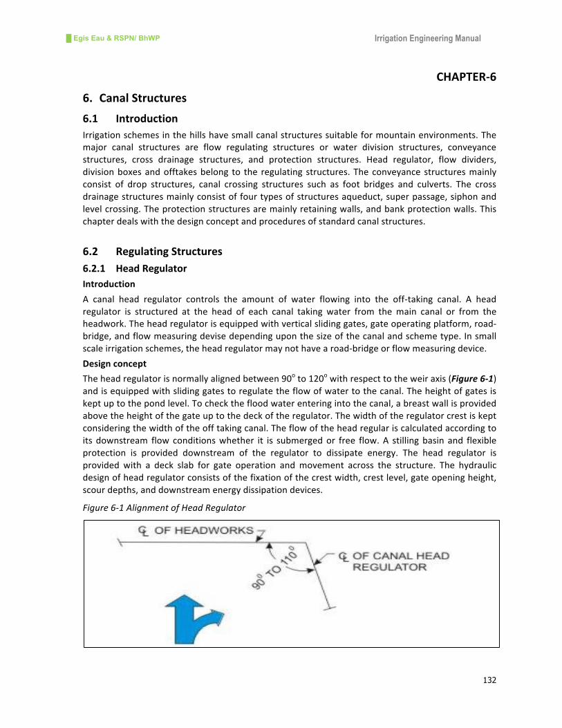
CHAPTER-6
6. CanalStructures
6.1 Introduction
Irrigationschemesinthehillshavesmallcanalstructuressuitableformountainenvironments.The
major canal structures are flow regulating structures or water division structures, conveyance
structures, cross drainage structures, and protection structures. Head regulator, flow dividers,
divisionboxesandofftakesbelong to the regulating structures.Theconveyancestructuresmainly
consist of drop structures, canal crossing structures such as foot bridges and culverts. The cross
drainagestructuresmainlyconsistoffourtypesofstructuresaqueduct,superpassage,siphonand
levelcrossing.Theprotectionstructuresaremainlyretainingwalls,andbankprotectionwalls.This
chapterdealswiththedesignconceptandproceduresofstandardcanalstructures.
6.2 RegulatingStructures
6.2.1 HeadRegulator
Introduction
A canal head regulator controls the amount of water flowing into the off-taking canal. A head
regulator is structured at the head of each canal taking water from themain canal or from the
headwork.Theheadregulatorisequippedwithverticalslidinggates,gateoperatingplatform,road-
bridge,andflowmeasuringdevisedependinguponthesizeofthecanalandschemetype.Insmall
scaleirrigationschemes,theheadregulatormaynothavearoad-bridgeorflowmeasuringdevice.
Designconcept
Theheadregulatorisnormallyalignedbetween90oto120
owithrespecttotheweiraxis(Figure6-1)
andisequippedwithslidinggatestoregulatetheflowofwatertothecanal.Theheightofgatesis
keptuptothepondlevel.Tocheckthefloodwaterenteringintothecanal,abreastwallisprovided
abovetheheightofthegateuptothedeckoftheregulator.Thewidthoftheregulatorcrestiskept
consideringthewidthoftheofftakingcanal.Theflowoftheheadregulariscalculatedaccordingto
its downstream flow conditionswhether it is submergedor free flow.A stillingbasin and flexible
protection is provided downstream of the regulator to dissipate energy. The head regulator is
provided with a deck slab for gate operation andmovement across the structure. The hydraulic
designofheadregulatorconsistsofthefixationofthecrestwidth,crestlevel,gateopeningheight,
scourdepths,anddownstreamenergydissipationdevices.
Figure6-1AlignmentofHeadRegulator
█ Egis Eau & RSPN/ BhWP Irrigation Engineering Manual
133
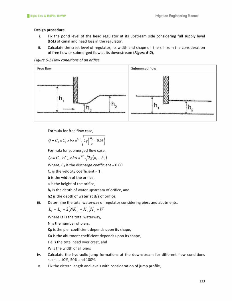
Designprocedure
i. Fix the pond level of the head regulator at its upstream side considering full supply level
(FSL)ofcanalandheadlossintheregulator,
ii. Calculatethecrestlevelofregulator,itswidthandshapeofthesillfromtheconsideration
offreefloworsubmergedflowatitsdownstream(Figure6-2),
Figure6-2Flowconditionsofanorifice
Freeflow Submersedflow
Formulaforfreeflowcase,
⎟⎠
⎞⎜⎝
⎛−×××= 63.02
12/3
a
hgabCCQ vd
Formulaforsubmergedflowcase,
( )21
2/32 hhgabCCQ vd −×××=
Where,Cdisthedischargecoefficient=0.60,
Cvisthevelocitycoefficient=1,
bisthewidthoftheorifice,
aistheheightoftheorifice,
h1isthedepthofwaterupstreamoforifice,and
h2isthedepthofwateratd/soforifice,
iii. Determinethetotalwaterwayofregulatorconsideringpiersandabutments,
( ) WHKNKLL eapet +++= 2
WhereLtisthetotalwaterway,
Nisthenumberofpiers,
Kpisthepiercoefficientdependsuponitsshape,
Kaistheabutmentcoefficientdependsuponitsshape,
Heisthetotalheadovercrest,and
Wisthewidthofallpiers
iv. Calculate the hydraulic jump formations at the downstream for different flow conditions
suchas10%,50%and100%.
v. Fixthecisternlengthandlevelswithconsiderationofjumpprofile,

█ Egis Eau & RSPN/ BhWP Irrigation Engineering Manual
134
vi. Checktheheadregulatorfloorforsub-surfaceflowconditions,
vii. Calculateupstreamanddownstreamcutoffdepths,
viii. Fixtheupstreamanddownstreamprotectionworks
DesignExampleofHeadRegulator
Designdata:
Fullsupplydischargeofcanal,Qc 0.44m3/s
Fullsupplylevelofcanal(FSL) 398.47 m
Designbedlevelofcanal(CBL) 398.04 m
PermissibleAfflux 0.50m
PondLevel 398.62 m
Riverbedlevel 396.56m
Highfloodlevel(HFL) 399.12m
Siltfactor 1
Safeexitgradient 0.20(1/5)
Fixationofcrestlevelandwaterway
Crestlevelofheadregulatoristakenas10cmhigherthancanalbedlevel,
=398.04+0.10=398.14m
Usingdrownedweirformula,
( ) ( )1121
223
2ghhLCghhLCQ ××+×××=
Where,C1=0.577andC2=0.80
h=pondlevel–FSL=398.62-398.47=0.15m
h1=FSL–crestlevel=398.47–398.14=0.33m
Then,L=Qc/(((2/3)*0.577*(sqrt(2*9.81)*0.15^(3/2))+(0.80*0.33*sqrt(2*9.81*0.33))))
L=0.57m,provideL=1.00m
Discharge passing through head regulator, Q = 2/3*0.577*1.00*0.15 *(sqrt(2*9.81*0.15))
+0.80*1.00*0.33*(sqrt(2*9.81*0.33))=0.55m3/s
Calculategateopeningforthecaseofhighflooddischarge,
ghACQ 2××=
Where,Ciscoefficient=0.62
Aistheareaoforifice,A=L*a,whereaistheheightoforifice,
histheheadcausingflow,h=u/sHFL–d/sFSL=399.12–398.47=0.65m
Then,a=Q/(0.62*L*sqrt(2*9.81*h)=0.44/(0.62*1*sqrt(19.62*0.65))=0.20m
Calculatevelocitythroughorifice,V1=Q/L*a=0.44/1*0.20=2.20m/s
Calculateheadlossatentry,he=0.5V12/2g=0.50*2.2^2/2*9.81=0.12m
TELu/soforificegate=HFL=399.12m
TELd/soforificegate=TELu/sofgate–entryheadloss=399.12-0.12=399.00m

█ Egis Eau & RSPN/ BhWP Irrigation Engineering Manual
135
Calculatetotalheadlossavailable=TELd/sgate–d/sFSL=399.00–398.47=0.53m
Dischargeintensity,q=Q/L=0.44/1.0=0.44m3/s/m
CalculateheadlossatFSLpassingatpondlevel,he=Pondlevel–FSL
he=398.62–398.47=0.15m
Dischargeintensity,q=Q/L=0.44/1.0=0.44m3/s/m
Themainhydraulicjumpcalculationsarecarriedoutintabularform(Table6-1).
Table6-1Hydraulicjumpcalculations
Descriptions Formaximumflood
flow
Forpondlevelflow
Dischargeintensity,q=1.84xH3/2
0.44 0.44
u/swaterlevel,m 399.12 398.62
d/swaterlevel,m 398.47 398.47
d/sTEL(d/sFSL) 398.47 398.47
u/sTEL(d/soforificegate) 399.00 398.62
Headloss 0.53 0.15
Postjumpdepth,D2-trialvalue 0.59 0.48
Pre-jumpdepth,
⎟⎟⎠
⎞⎜⎜⎝
⎛+
×+−= 2
2
2
2
21
4
1/2
2
1D
D
qgDD
0.10 0.14
d/sspecificenergy,
( )222
222/ DgqDEf ×+=
0.62 0.52
u/sspecificenergy,
( )122
112/ DgqDEf ×+=
1.14 0.67
Ef1-Ef2=Headloss(shouldbeequal
toabovevalue)
0.53 0.15
Levelofjump=d/sTEL-Ef2 397.85 397.95
Lengthofconcretefloor,
L=5(D2-D1)
2.46 1.70
FroudenoF=q/(g*D31)0.5
4.63 2.80
d/sfloorlevelisprovidedat(minimumofjumplevel) 397.85 m
d/sfloorlength(maximumoflengthofconcretefloor) 2.46mroundupto3.0m
DepthofCut-offfromscourconsideration
Dischargeintensityofheadregulator=0.44m3/s/m
Scourdepth,R=1.35x(q2/f)1/3=1.35*(0.44^2/1)^1/3=0.78m
Ond/ssideallowcut-offdepthas1.75R=1.75*0.78=1.37m

█ Egis Eau & RSPN/ BhWP Irrigation Engineering Manual
136
RLofbottomofscourhole=d/sFSL–cut-offdepth=398.47–1.37=397.10m
Adoptd/scutofflevelas396.50m
Depthofd/scut-offfromcanalbed=Designbedlevelofcanal–bottomlevelofcut-off
d=398.04–396.50=1.54m
Providethicknessoflaunchingapronas0.75m
Lengthoflaunchingapron=3m
Totalfloorlengthandexitgradient
Theexitgradientshouldbecheckedfortheconditionthatthecanaliscompletelyclosedwhenhigh
floodispassingintheriver;thisprovidesworststaticcondition.
Maximumstatichead,H=u/sHFL–d/sfloorlevel=399.12–397.85=1.27m
Depthofd/scutoff=d/sfloorlevel–cut-offlevel=397.85–396.50=1.35m
Exitgradient,H
dGE
=λπ
1
Hence,λπ
1 =1/5*1.35/1.27= 0.212
FromKhosla'sexitgradientcurve,α(alfa)=2.2
Requiredtotalfloorlength,b=αxd=2.20*1.54= 3.39m
Adopttotalfloorlength=7.00m
Thefloorlengthshallbeprovidedasperfollowingproportion:
Crestwidthofheadregulator=1.00m
d/shorizontalfloorlength,=3.24m
d/sglacislengthwith3:1slope=3*u/sfloor–d/sfloor=3(398.14-397.85)=0.87m
Balanceshouldbeprovidedasupstreamfloor=2.00m
Totalfloorlength=2.00+1.00+0.87+3.24=7.11m
Figure6-3DesignSketchofheadregulator

█ Egis Eau & RSPN/ BhWP Irrigation Engineering Manual
137
Pressurecalculations
Letthefloorthicknessintheu/sbe0.50mandnearthed/scut-offbe0.50m
Determinetheupliftpressureactingonthefloorand%pressuresatu/sandd/ssheetpiles:
%pressureatu/ssheetpileline
Upstreamcutoff,d1=398.14–396.56=1.58m
Lengthoffloor,b=7.11mandu/scutoffdepth,d1=1.58m
Then,1/α=d1/b=1.58/7.11=0.22,α=4.61
( ) 2/112αλ ++= =(1+sqrt(1+4.61^2))/2=2.86
FromKhosla’scurves,φE=40.30%
φD=27.47%
φC1=100-φE=100-40.30=59.70%
φD1=100–φD=100-27.47=72.53%
Applycorrectiontotheabovevalues,
Thicknessofu/sfloor,t1=0.50m
Cf1correctionfordepth=t1/d1(φD1–φC1)=0.50/1.58*(72.53-59.70)=4.06(+ve)
Cf2correctionforinterferenceofd/scutoff
Khosla’sformula,⎟⎠
⎞⎜⎝
⎛ +×⎟⎟
⎠
⎞⎜⎜⎝
⎛=
b
dD
b
DC
1
50.0
1
19
d1=397.85-0.50-396.50=0.85m
D=398.14-0.5-396.50=1.14m
b1=6.61m
b= 7.11m
C=19*(1.14/6.61)^0.5*(1.14+0.85)/7.11=2.25%(+ve)
φCcorrected =59.70+4.06+2.25= 66.01%say66.00%
Downstreamcutoff,d2=397.85-396.50=1.35m
Lengthoffloor,b=7.11m andd/scutoffdepth,d1=1.35m
Then,1/α=d2/b=1.35/7.11=0.19
FromKhosla’scurves,φE1=38%
φD1= 26%
φE1-φD1=38–26=12.00%
φE1correctionfordepth=0.50*12/1.35=4.44(-ve)
φE1correctionforinterferenceduetou/scutoff
d=397.85-0.50-396.50=0.85m
D=398.14-0.50-396.50=1.14m
⎟⎠
⎞⎜⎝
⎛ +×⎟⎟
⎠
⎞⎜⎜⎝
⎛=
b
dD
b
DC
1
50.0
1
19 =19(1.14/6.11)^0.5*(0.85+1.14/7.11)=2.29%(-ve)
φEcorrected =12.00-4.44-2.29=5.27%say5.30%
█ Egis Eau & RSPN/ BhWP Irrigation Engineering Manual
138
φC=66.00% andφE=5.30%
Floorthickness
Themaximumstaticheadwilloccuronthefloorwhenthereisnoflowinthecanalbutmaximum
floodispassingdownriver.Inthiscasethemaximumstatichead=1.27m
Downstreamfloor
At1mfromd/send
Unbalancedhead=(66.00-5.30)/100*1.27*1.00/7.11+5.30*1.27/100=0.18m
Floorthickness=0.18 /(2.24-1)=0.15m
Providefloorthickness=0.50throughoutthebasin
Protectionworksbeyondimperviousfloor
i. Upstreamblockprotection
Scourdepth,R=1.35(q2/f)
1/3=1.35(0.44^2/1)^1/3=0.78m
Anticipatedscour=1.50*R=1.50*0.79=1.17m
Upstreamscourlevel=u/sHFL-anticipatedscourlevel=398.14–1.17=396.97m
Scourdepth,Dbelowu/sfloor=crestlevelofundersluice–scourlevel=1.58m
Volumeofblockprotectiontobegiven(D)=1.58m3/m
Provide1.5mx1.5mx1.0mconcreteblockover0.50mthickgravel
Thelengthrequired= 1.58/(1.0+0.50)=1.05m
Providetworowsoftheaboveblockinalengthof2.00m
ii. U/sLaunchingapron
Quantityoflaunchingapronshouldbe2.25Dm3/m
Thicknessoflaunchingapron=1.00m
Thelengthrequired=2.25*1.58/1.00=3.55m
Providelaunchingapronas4.00mlength
iii. Downstreamprotection
Scourdepth,R=0.78m
Anticipatedscour=2*R=1.56m
Downstreamscourlevel=FSL–anticipatedscour=398.47–1.56=396.91m
Scourdepth,Dbelowd/sfloor=d/sfloorlevel–scourlevel=397.85–396.91
D=0.94mSay1.00m
iv. Invertedfilter
Thelengthofinvertedfilter=Dmandthicknessequaltothed/slaunchingapron Providerowof
1.50mx1.50mx1mconcreteblockwith10cmgapfilledwithpeagravelover0.5 mthickgraded
filter
Thelengthrequired=1.00/(1.0+0.50)=0.66m=1m
v. D/sLaunchingapron
Quantityoflaunchingapronshouldbe2.25Dm3/m
Thicknessoflaunchingapron=1.00m
█ Egis Eau & RSPN/ BhWP Irrigation Engineering Manual
139
Thelengthrequired=2.25*1/1.00=2.25m
Providelaunchingapronas3.00mlength
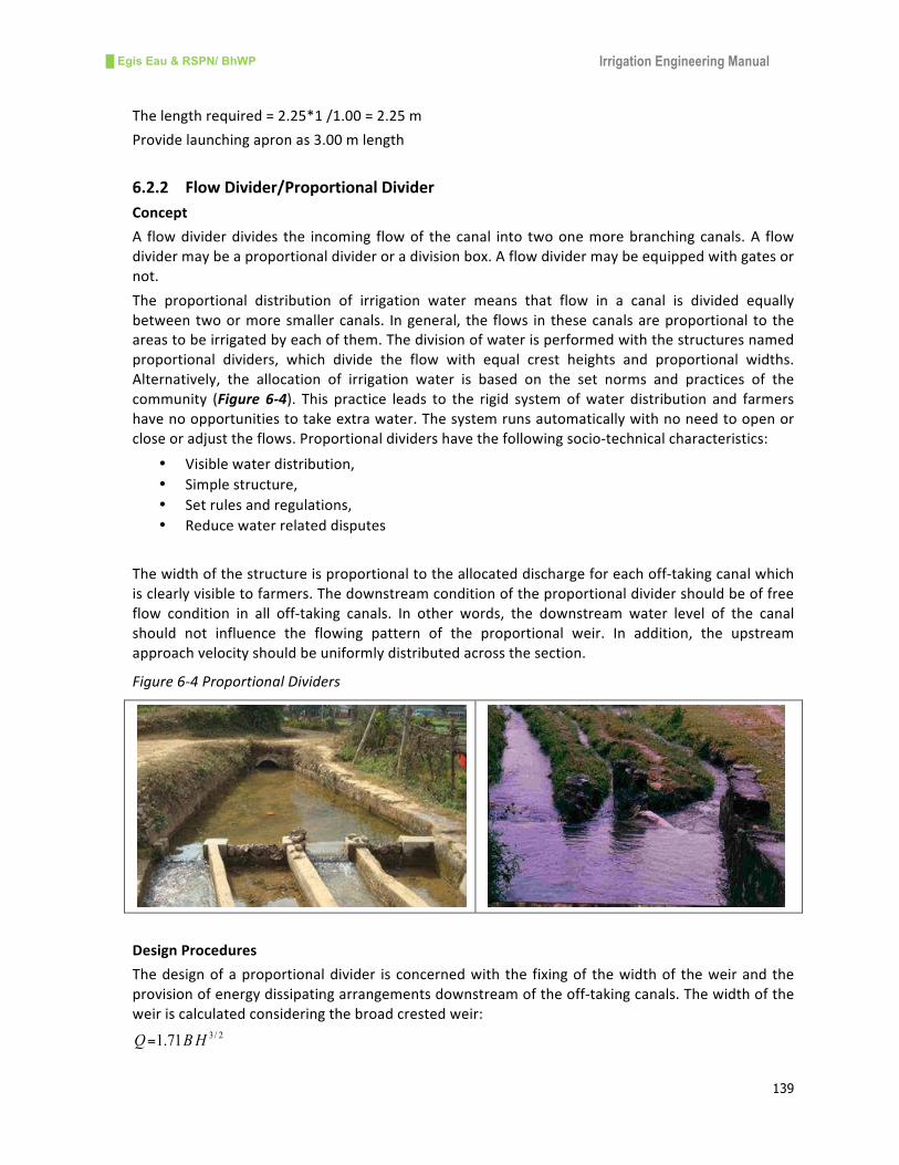
6.2.2 FlowDivider/ProportionalDivider
Concept
A flowdividerdivides the incoming flowof thecanal into twoonemorebranchingcanals.A flow
dividermaybeaproportionaldivideroradivisionbox.Aflowdividermaybeequippedwithgatesor
not.
The proportional distribution of irrigation water means that flow in a canal is divided equally
betweentwoormoresmallercanals. Ingeneral, the flows in thesecanalsareproportional to the
areastobeirrigatedbyeachofthem.Thedivisionofwaterisperformedwiththestructuresnamed
proportional dividers, which divide the flow with equal crest heights and proportional widths.
Alternatively, the allocation of irrigation water is based on the set norms and practices of the
community (Figure 6-4). This practice leads to the rigid systemofwater distribution and farmers
havenoopportunitiestotakeextrawater.Thesystemrunsautomaticallywithnoneedtoopenor
closeoradjusttheflows.Proportionaldividershavethefollowingsocio-technicalcharacteristics:
• Visiblewaterdistribution,
• Simplestructure,
• Setrulesandregulations,
• Reducewaterrelateddisputes
Thewidthofthestructureisproportionaltotheallocateddischargeforeachoff-takingcanalwhich
isclearlyvisibletofarmers.Thedownstreamconditionoftheproportionaldividershouldbeoffree
flow condition in all off-taking canals. In other words, the downstream water level of the canal
should not influence the flowing pattern of the proportional weir. In addition, the upstream
approachvelocityshouldbeuniformlydistributedacrossthesection.
Figure6-4ProportionalDividers
DesignProcedures
Thedesignofaproportionaldivider isconcernedwith the fixingof thewidthof theweirandthe
provisionofenergydissipatingarrangementsdownstreamoftheoff-takingcanals.Thewidthofthe
weiriscalculatedconsideringthebroadcrestedweir:
2/371.1 HBQ=

█ Egis Eau & RSPN/ BhWP Irrigation Engineering Manual
140
Where,Bisthewidthoftheweir,andHistheheightofthecrest,
The width of the weir is proportional to the discharge in free flow conditions. The downstream
energydissipationiscalculatedasperthehydraulicjumpcalculations.Forsmallscalestructures,the
lengthofthebasinis5to6timestheheightofthedrop(differenceinwaterlevelsofupstreamand
downstreamcanals).
DesignExampleofProportionalDivider
Data
Parentcanaldischarge,Qp 220l/s
Dischargebranchcanal-1,Q1 132l/s
Dischargeofbranchcanal-2,Q2 88l/s
Waterdepthinparentcanal,Dp 0.40m
Waterdepthinbranchcanal-1,D1 0.35m
Waterdepthinbranchcanal-2,D2 0.30m
Bedwidthofparentcanal ,Bp 0.40m
Bedwidthofbranchcanal-1,B1 0.35m
Bedwidthofbranchcanal-2,B2 0.30m
Calculations
Providewidthofweirslightlywiderthanparentcanalwidth,W=0.50m
Calculatethewidthofweirforcanal-1 W1=W*Q1/Qp=0.50*0.132/0.220=0.30m
Calculatethewidthofweirforcanal-1 W2=W*Q2/Qp=0.50*0.88/0.220=0.20m
Checkthetotalwidthoftheweir,W=W1+W2=0.30+0.20=0.50m,OK
Hence,thedesignisacceptable.
6.2.3 FieldOutlets/Offtakes
Field outlets or offtakes are small structure used to supply water from canals to the field.
Dependinguponthetype,sizeand importanceofthescheme,outletsareofvarioustypes.The
maindesignobjectiveoftheseoutletsistosupplyirrigationwaterequitablyuptothetailendof
the scheme. In large irrigation systems, outlets are both gated and ungated. For small scale
irrigation,outletsareeithersimplepipeoutlets fixedat theheadof theprimarycanal/ tertiary
canalsoropencutopenings.Thecontrolofwater inpipeoutletscouldbemanagedbymanual
inspection, closingwith localmaterial or letting to flow continuously. Inopen cutoutlets, stop
log grooves exist for the insertion of wooden planks. In hill schemes, these outlets provide
sufficientdroptotheirrigatedareawhichisconsiderablylowerthantheparentcanal.
DesignConcept:
Thedesignofoutletsshouldmeetthefollowingrequirements:
§ Allowfarmerstoallocatetheavailablewateramongtheusersintheagreedmanner,
§ Allowfarmersmaximumflexibilityofoutletoperationduringnormalandlow-flowperiodsin
thesupplycanal,

█ Egis Eau & RSPN/ BhWP Irrigation Engineering Manual
141
Theallocationanddistributionofavailablewatermayleadtoconflictamongusers,especiallyduring
periodsoflowwateravailability.Inaddition,duringperiodsoflowflowinthecanal,moreeffective
waterdistributioncanbeachievedbyapplyingrotationof flowamongtheusers.Thiswill require
everyoutlettobedesignedinsuchamannerthat:
§ on/offflowcontrolthroughtheoutletispossible,
§ efficient flow rates are maintained through the outlet even when the water level in the
supplycanalislow
Simplewoodenplanksarethemostappropriateforon/offflowcontrolinsmallirrigationschemes
whether theoutlets arepipedoutletsoropen cut in lined canals.Whenwater level is low in the
parent canal during a low flow period, the flow in the outlet is also low. To divert the high flow
towardstheoutletacheckstructureisessentialontheparentcanal.
Insmallirrigationschemes,threetypesoffieldoutletsorofftakesareusedindevelopingcountries:
• Simpleopening,
• Simpleopeningwithdownstreamdrop,and
• Pipeoutlet
A simple opening type offtake is provided in small irrigation schemeswith earthen sections. The
openings can easily be opened or closed by farmers using locally availablemud clods, stones or
inserting wooden plans on the grooves. The maximum size of the opening should be 300mm.
However,smalleropeningscouldalsobemadeupto100mminsize.Asketchofatypicalstructure
isshownhere(Figure6-5).
Figure6-5Typicaloutletstructure
█ Egis Eau & RSPN/ BhWP Irrigation Engineering Manual
142
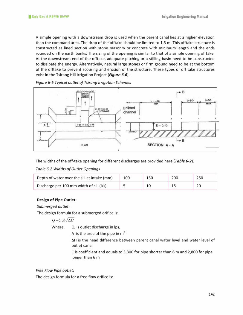
Asimpleopeningwithadownstreamdropisusedwhentheparentcanalliesatahigherelevation
thanthecommandarea.Thedropoftheofftakeshouldbelimitedto1.5m.Thisofftakestructureis
constructed as lined sectionwith stonemasonry or concretewithminimum length and the ends
roundedontheearthbanks.Thesizingoftheopeningissimilartothatofasimpleopeningofftake.
Atthedownstreamendoftheofftake,adequatepitchingorastillingbasinneedtobeconstructed
todissipatetheenergy.Alternatively,naturallargestonesorfirmgroundneedtobeatthebottom
of theofftaketopreventscouringanderosionof thestructure.Thesetypesofoff takestructures
existintheTsirangHillIrrigationProject(Figure6-6).
Figure6-6TypicaloutletofTsirangIrrigationSchemes
Thewidthsoftheoff-takeopeningfordifferentdischargesareprovidedhere(Table6-2).
Table6-2WidthsofOutletOpenings
Depthofwateroverthesillatintake(mm) 100 150 200 250
Dischargeper100mmwidthofsill(l/s) 5 10 15 20
DesignofPipeOutlet:
Submergedoutlet:
Thedesignformulaforasubmergedorificeis:
HACQ Δ=
Where, Qisoutletdischargeinlps,
Aistheareaofthepipeinm2
∆Histheheaddifferencebetweenparentcanalwater levelandwater levelof
outletcanal
Ciscoefficientandequalsto3,300forpipeshorterthan6mand2,800forpipe
longerthan6m
FreeFlowPipeoutlet:
Thedesignformulaforafreefloworificeis:

█ Egis Eau & RSPN/ BhWP Irrigation Engineering Manual
143
HACQ Δ=
Where, Qisoutletdischargeinlps,
Aistheareaofthepipeinm2
∆Histheheaddifferencebetweenparentcanalwater levelandwater levelof
outletcanal
Ciscoefficientandequalsto2760
TypicalsketchesofsubmergedandfreeflowoutletsarepresentedinFigure 6-7.
DesignExampleofPipeOutlet
Insubmergedpipeoutlethavinga100mmdiameterHDPpipewitha0.25mheaddifference,the
dischargeis:
Q=3300x0.102x0.25
0.5=13l/s
In free flowpipe outlet having a 100mmdiameterHDPpipewith a 0.25mheaddifference, the
dischargeis:
Q=2760x0.102x0.25
0.5=11l/s
The detailed worked out examples of pipe outlets for both submersed and free flow cases are
presentedhere(Table6-3).
Table6-3DischargethroughPipeOutlets(Pipelength<6m)
Headloss
(m)
PipeDiameter(mm)
100 150 200 250 300
Submergedflow(l/s)
0.05 6 13 23 36 52
0.10 8 18 33 51 74
0.15 10 23 40 63 90
0.20 12 26 46 72 104
0.25 13 29 52 81 117
0.30 14 32 57 89 128
Freeflow(l/s)
0.15 8 19 34 52 76
0.20 10 22 39 61 87
0.25 11 24 43 68 98
0.30 12 27 47 74 107
0.35 13 29 51 80 115
0.40 14 31 55 86 123
0.45 15 33 58 91 131
0.50 16 34 61 96 138

█ Egis Eau & RSPN/ BhWP Irrigation Engineering Manual
144
Figure6-7PipeOutlets

█ Egis Eau & RSPN/ BhWP Irrigation Engineering Manual
145
6.3 DropStructures
6.3.1 GeneralConcept
Dropstructuresarerequired inacanalwhenthetopography issteeperthanthecanalgradient. If
drops are not provided, erosion will occur in the canal. A drop structure may be provided at a
location where the canal water level outstrips the ground level but before the bed of the canal
comesintofillings(Figure6-8).Inthehills,ifthecanalisinrock,quitesteeplygradedcanalscanbe
madewithnodropstructures.Four typesofdropstructuresaresuitable for small scale irrigation
schemes:
• Verticalorstraightdrop,
• Inclineddroporchutedrop,
• Pipedrop,and
• Cascadedrop
Figure6-8Definitionsketchofdropstructure
Inallthesedropstructures,strongerwallsandfloorsareneededtoresisterosion,impactforcesof
water and abrasion. In addition, complex stilling basins are required to control turbulence
associatedwithlargedropheights.Inremotehillyareas,theconstructionoflargedropstructuresis
difficultandundesirable.Hence, it issuggestedto limitdropheightsto2mforverticalandchute
drops and 4m for pipe and cascade drops. For small irrigation schemes, drop structures can be
combinedwithcontrolorcheckstructures.
Thebasichydraulicprincipleforallofthesedropstructuresisthedissipationofexcessenergyasthe
water drops fromahigh level to a low level. All of thewater’s excess energymust bedissipated
insidethedropstructurebeforethewaterisallowedintothedownstreamcanal.Energyofflowing
watercanbedissipatedby:
• Hydraulicjumps,
• Allowingtheflowtostriketobaffles,baffleblocks,andraisedsills,and
• Usingwatercushion
A simple hydraulic jump, or a combination of a hydraulic jumpwith a raised sill, standingwater
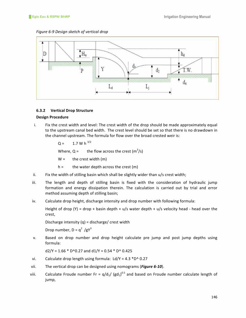
pools,orcushionsarethemostcosteffectivemeasuresinhillirrigationschemes(Figure6-9).
█ Egis Eau & RSPN/ BhWP Irrigation Engineering Manual
146
Figure6-9Designsketchofverticaldrop
6.3.2 VerticalDropStructure
DesignProcedure
i. Fixthecrestwidthandlevel:Thecrestwidthofthedropshouldbemadeapproximatelyequal
totheupstreamcanalbedwidth.Thecrestlevelshouldbesetsothatthereisnodrawdownin
thechannelupstream.Theformulaforflowoverthebroadcrestedweiris:
Q= 1.7Wh3/2
Where,Q= theflowacrossthecrest(m3/s)
W= thecrestwidth(m)
h= thewaterdepthacrossthecrest(m)
ii. Fixthewidthofstillingbasinwhichshallbeslightlywiderthanu/screstwidth;
iii. The length and depth of stilling basin is fixed with the consideration of hydraulic jump
formation and energy dissipation therein. The calculation is carried out by trial and error
methodassumingdepthofstillingbasin;
iv. Calculatedropheight,dischargeintensityanddropnumberwithfollowingformula:
Heightofdrop(Y)=drop+basindepth+u/swaterdepth+u/svelocityhead-headoverthe
crest,
Dischargeintensity(q)=discharge/crestwidth
Dropnumber,D=q2/gY
3
v. Based on drop number and drop height calculate pre jump and post jump depths using
formula:
d2/Y=1.66*D^0.27andd1/Y=0.54*D^0.425
vi. Calculatedroplengthusingformula:Ld/Y=4.3*D^0.27
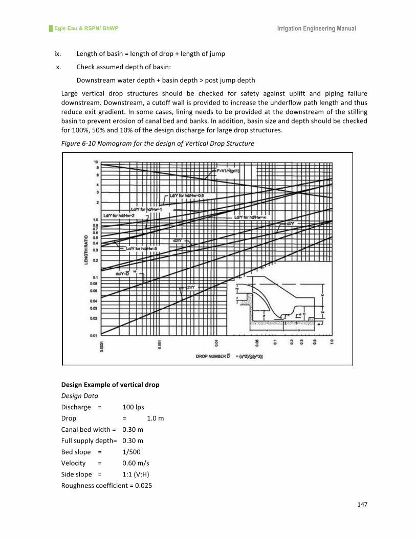
vii. Theverticaldropcanbedesignedusingnomograms(Figure6-10).
viii. CalculateFroudenumberFr=q/d1/ (gd1)0.5 andbasedonFroudenumber calculate lengthof
jump,
█ Egis Eau & RSPN/ BhWP Irrigation Engineering Manual
147
ix. Lengthofbasin=lengthofdrop+lengthofjump
x. Checkassumeddepthofbasin:
Downstreamwaterdepth+basindepth>postjumpdepth
Large vertical drop structures should be checked for safety against uplift and piping failure
downstream.Downstream,acutoffwallisprovidedtoincreasetheunderflowpathlengthandthus
reduceexitgradient. Insomecases, liningneeds tobeprovidedat thedownstreamof thestilling
basintopreventerosionofcanalbedandbanks.Inaddition,basinsizeanddepthshouldbechecked
for100%,50%and10%ofthedesigndischargeforlargedropstructures.
Figure6-10NomogramforthedesignofVerticalDropStructure
DesignExampleofverticaldrop
DesignData
Discharge = 100lps
Drop = 1.0m
Canalbedwidth= 0.30m
Fullsupplydepth= 0.30m
Bedslope = 1/500
Velocity = 0.60m/s
Sideslope = 1:1(V:H)
Roughnesscoefficient=0.025

█ Egis Eau & RSPN/ BhWP Irrigation Engineering Manual
148
Calculations
Crestwidthandlevel
Crestwidth=slightlymorethancanalbedwidth=0.4m
Headofwaterovercrest,hwisgivenbytheexpression,
Q=1.7whw3/2
givinghw=0.28m
Upstreamflowdepthinthecanal=0.3m.Thereforetopreventdrawdowneffectthecrestmustbe
setat0.30–0.28=0.02mabovethebedoftheupstreamcanal;forpracticalreasons,allow0.05m.
ThusP=0.05m,
Widthofstillingbasin=U/Screstwidth+0.1m=0.40+0.10=0.50m
Thedesigncalculationfromthispointonwardsisofatrialanderrornature.Themainhydraulic
calculationsfordeterminingthelengthofdrop,lengthofjumpandthesillheightrequire
assumptionofstillingbasindepth,
Assumestillingbasindepth(d4)=0.20m
Calculatevelocityhead=v2/2g=0.30^2/19.62=0.016m
Then,heightofdrop(Y)=drop+basindepth+waterdepth+velocityhead-headoverthecrest
Y=1.0+0.20+0.30+0.016-0.28=1.24m
qisthedischargeperunitwidthinthestillingbasin=0.1/0.5=0.2m3persec
Dropnumber,D=q2/gY
3=0.0011
d2/Y=1.66*D^0.27=0.26thenpostjumpdepth(d2)=1.24*0.26=0.32m
d1/Y=0.54*D^0.425=0.029thenprejumpdepth(d1)=1.24*0.029=0.04m
Ld/Y=4.3*D^0.27=0.86thenlengthofdrop(Ld)=0.68*1.24=0.84m
CalculateFroudenumberFr=q/d1/(gd1)0.5=0.2/0.04/(9.81*0.04)^0.5=7.98
ForFr=7.98Lj/d2=6.25()thenlengthofjump(Lj)=6.25*0.32=2.03m
Totallengthofbasin=lengthofdrop+lengthofjump=0.84+2.03=2.87msay3.00m
Checktheassumeddepthofbasin
Downstreamwaterdepth+basindepth>postjumpdepth
0.30+0.20=0.50m>0.32m,hencebasindepthof0.20misOK
Figure6-11RelationbetweenFroudenumberandlengthofjump

█ Egis Eau & RSPN/ BhWP Irrigation Engineering Manual
149
6.3.3 ChuteDropStructure
DesignConcept
Inhillyregions,canalalignmenthastopassthroughsteepslopesandachutedropisappropriatefor
slopesupto1:2.Thechuteflumeandstillingbasinshouldbemadein1:3slopeswithstonemasonry
orconcreterectangularsection(Figure6-12).Forlongchutes,stillingbasinsareprovidedforevery
10mdropinheight.
Figure6-12Designsketchofchutedrop
DesignProcedure
i. Theflumewidth(W)shouldbemadethesameastheupstreambedwidthofthecanalor
slightlynarrower,
ii. Thecrestheightiscalculatedusingbroadcrestedweirformulaas:
Q=1.71Wh3/2
Where,Qistheflowacrossthecrest(m3/s),
Wisthecrestwidth(m),and
histheheadoverthecrest(m)
iii. Calculatedischargeintensity,q=Q/W
iv. Calculatecriticaldepthofflow3
2
g
qdc =
v. CalculatedroptocriticaldepthratioH/dc,Histhedifferenceinu/sandd/senergylevel,
vi. Fromgraphortablefindd1/dcandcalculateprejumpdepthd1,
vii. CalculateFroudenumber
1
1
gd
VF = whereV1=q/d1
viii. Calculatepostjumpdepthd2from ( )1812
1 2
1
2 −+= Fd
d
ix. FindfromgraphlengthofjumpL/d2
x. Calculatetotallengthofdrop
█ Egis Eau & RSPN/ BhWP Irrigation Engineering Manual
150
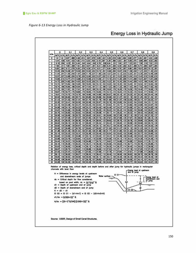
Figure6-13EnergyLossinHydraulicJump

█ Egis Eau & RSPN/ BhWP Irrigation Engineering Manual
151
DesignExampleofChuteDrop
Data
Discharge=220l/s
U/sandd/scanalwaterdepths=0.50m
Canalbedwidth=0.75m
Dropheight=2m
Calculations
Fixthewidthofchutesameaswidthofu/scanalbed=0.75m
CalculateheadoverthecrestfromQ= 1.71Wh3/2
H=(Q/1.71W)^2/3=(0.22/1.71*0.4)^2/3=0.309m
Sincewaterdepthis0.5mputcrestheightof0.50-0.31=0.19m
Calculatedischargeintensityq=Q/W=0.22/0.75=0.293m3/s/m
Calculatecriticaldepth 3
2
g
qdc = =(0.293^2/9.81)^1/3=0.206m
Differenceinu/sandd/senergylevelisequaltodropheight=2m
ThenH/dc=2/0.206=9.70
Fromthegraphofenergylossinhydraulicjump,d1/dc=0.208(Figure 6-13)
Then,d1=d1/dc*dc=0.208*0.206=0.043m
CalclatevelocityatthestartofjumpV1=q/d1=0.293/0.043=6.84m/s
CalculateFroudenumber1
1
gd
VF = =6.84/(9.81*0.043)^1/2=10.54
Calculate ( )1812
1 2
1
2 −+= Fd
d=½((1+8*10.54^2)^0.5–1)=14.41
Then,d2=14.41*0.043=0.62m
FindfromgraphLj/d2=6.25,thenLj=6.25*0.62=3.86m(Figure 6-11)
Providelengthofbasin=4.00m
Anddepthofbasin=d2-d/swaterdepth=0.62-0.50=0.12m
Providedepthofbasin=0.15m
Hence,designisacceptable.
6.3.4 PipeDropStructure
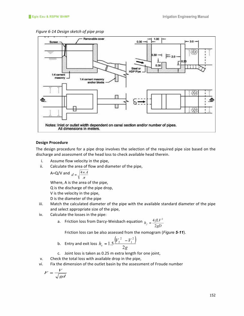
DesignConcept
Pipedropsmaybeusedforfallsupto4mormoreandareanobviouschoicewherearoadcrossing
isalsorequired.Energydissipationinpipedropsisachievedbyeitherbaffledoutletsorstillingwells.
Thepipesneedtobewellconstructedandwatertight.However,pipesaresusceptibletoblockage
bydebris. Themaximumvelocity in thepipedependsupon theenergydissipationarrangements.
Forsmallirrigationschemes,HDPpipeswithamaximumvelocityofupto3m/sareconsideredand
anoutletboxwithasmallbafflewallissuitablefordownstreamenergydissipation(Figure6-14).To
checkwater hammer, adequate submergence is necessary at the entry and exit of the pipe. The
minimumsubmergenceshouldbehalfofthesectiondepthabovethesoffit.
█ Egis Eau & RSPN/ BhWP Irrigation Engineering Manual
152
Figure6-14Designsketchofpipeprop
DesignProcedure
Thedesignprocedureforapipedropinvolvestheselectionoftherequiredpipesizebasedonthe
dischargeandassessmentoftheheadlosstocheckavailableheadtherein.
i. Assumeflowvelocityinthepipe,
ii. Calculatetheareaofflowanddiameterofthepipe,
A=Q/Vandπ
Ad
×=4
Where,Aistheareaofthepipe,
Qisthedischargeofthepipedrop,
Visthevelocityinthepipe,
Disthediameterofthepipe
iii. Matchthecalculateddiameterofthepipewiththeavailablestandarddiameterofthepipe
andselectappropriatesizeofthepipe,
iv. Calculatethelossesinthepipe:
a. FrictionlossfromDarcy-WeisbachequationgD
fLVh f
2
42
=
Frictionlosscanbealsoassessedfromthenomogram(Figure 5-11).
b. Entryandexitloss( )
g
VVhe
25.1
2
1
2
2−
=
c. Jointlossistakenas0.25mextralengthforonejoint,
v. Checkthetotallosswithavailabledropinthepipe,
vi. FixthedimensionoftheoutletbasinbytheassessmentofFroudenumber
gd
VF =

█ Egis Eau & RSPN/ BhWP Irrigation Engineering Manual
153
Where,Vistheincomingvelocityofpipeflowinm/s,gistheaccelerationduetogravity
inm/sec2,disthedepthofflowenteringthebasinandisthesquarerootoftheflow
area,
AccordingtoFroudenumberoftheincomingflowthewidthtodepth(W/D)ratioiscalculatedfrom
USBRgraph(Figure6-15).Theotherdimensionoftheoutletbasindependsuponthewidthofthe
basin.
Depthofbasinatu/s(H)=¾widthofbasin(W),
Lengthofbasin(L)=4/3W,
Lengthoffirstcompartment(a)=1/2W,
Heightofbafflewall(b)=3/8W,
Depthofstillingbasinbelowpipeinvert(d)=1/6W,
Figure6-15Designgraphofoutletbasin(USBR)
Forsmallirrigationschemesbasindimensionsarefixedtentatively.

█ Egis Eau & RSPN/ BhWP Irrigation Engineering Manual
154
DesignExampleofPipeDrop
Data
Designdischarge(Q) 132l/s
Canalwaterdepth 0.35m
Canalbedwidth 0.35m
Velocityofflow 0.54m/s
Availabledrop 3.00m
Calculations
Assumevelocityinpipe(Vp)=2.5m/s
Calculaterequiredpipeflowarea(A) =Q/Vp=0.132/2.5=0.053m2
Finddiameterofpipe(D)=sqrt(4*A/π)=(4*0.053/3.14)^0.5=0.259m
Thenearestavailablepipesize(D)=280mm(outerdiameter)
Findinnerdiameterofpipe(d)=D-2*thicknessofpipe=280-2*9=262mm>259mm
Calculateheadlossinpipe,
Frictionheadlossfromtablefor100mlength(hf)=1.28mandfor15mhf=0.192m
Velocityofflowinpipeaspertable(Vp)=2.30m/s
Calculateentryandexitloss(he)=( )
g
VVhe
25.1
2
1
2
2−
=
he=1.5(2.3^2-0.54^2)/2*9.81=0.38m
Calculatetrashrackloss(ht)=0.10m(assumed)
Calculatejointandbendloss(hj)[email protected]
hj=1.28/100*0.50*100=0.064m
Totalheadloss=hf+He+ht+hj=0.192+0.38+0.10+0.06=0.74m
Thetotalheadlossislessthanavailableheadatsite(0.74m<3m)andhence,OK
Calculatebasindimensions
Flowareainpipe(A)=πD^2/4=3.14*0.262^2/4=0.054m2
Calculatethedepthofflowenteringthebasin(d)=sqrt(A)=(0.054)^0.5=0.23m
CalculateFroudenumber
gd
VF =
=2.3/(9.81*0.23)^0.5=1.53
Findwidthtodepthrationfromgraph(USBR)forF=1.53,W/D=3.55
Hence,widthofbasin=3.55*0.23=0.82m
Calculateotherdimensionsofthebasin:
Lengthofbasin(L)=4/3W=4/3*0.82=1.10m
Heightofbasin(H)=3/4W=¾*0.82=0.62m
Lengthoffirstcompartment(a)=1/2W=1/2*0.82=0.41m
Depthofbasinbelowpipeinvert(d)=W/6=0.82/6=0.14m
Heightofbafflewall(b)=3/8W=3/8*0.82=0.31m
Hence,thedesignisacceptable.
█ Egis Eau & RSPN/ BhWP Irrigation Engineering Manual
155
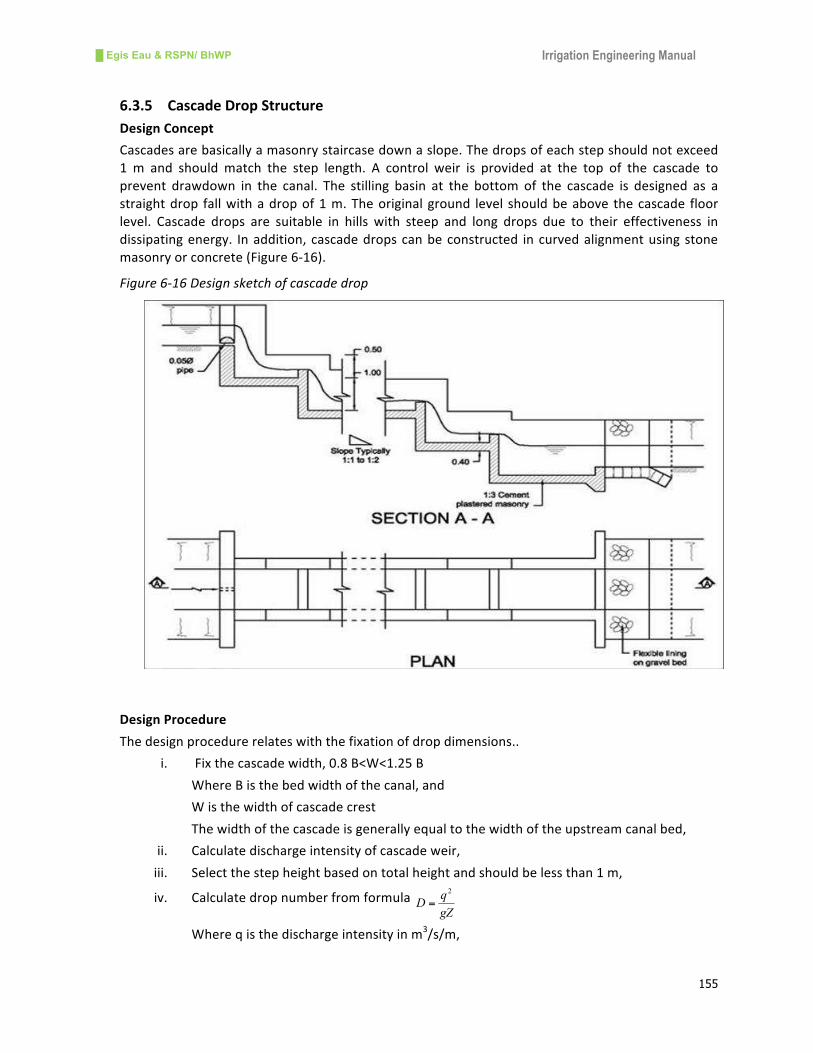
6.3.5 CascadeDropStructure
DesignConcept
Cascadesarebasicallyamasonrystaircasedownaslope.Thedropsofeachstepshouldnotexceed
1 m and should match the step length. A control weir is provided at the top of the cascade to
prevent drawdown in the canal. The stilling basin at the bottom of the cascade is designed as a
straightdrop fallwithadropof1m.Theoriginalground level shouldbeabove thecascade floor
level. Cascade drops are suitable in hills with steep and long drops due to their effectiveness in
dissipatingenergy. Inaddition,cascadedropscanbeconstructed incurvedalignmentusingstone
masonryorconcrete(Figure6-16).
Figure6-16Designsketchofcascadedrop
DesignProcedure
Thedesignprocedurerelateswiththefixationofdropdimensions..
i. Fixthecascadewidth,0.8B<W<1.25B
WhereBisthebedwidthofthecanal,and
Wisthewidthofcascadecrest
Thewidthofthecascadeisgenerallyequaltothewidthoftheupstreamcanalbed,
ii. Calculatedischargeintensityofcascadeweir,
iii. Selectthestepheightbasedontotalheightandshouldbelessthan1m,
iv. CalculatedropnumberfromformulagZ
qD
2
=
Whereqisthedischargeintensityinm3/s/m,

█ Egis Eau & RSPN/ BhWP Irrigation Engineering Manual
156
Gistheaccelerationduetogravity9.81m/s,
Zisthestepheightinm
v. Calculatehydraulicdroplengthfromformula 27.03.4 DZL
d××=
vi. CalculatethelengthofstepasL>Ld+0.10andcomparewithavailablegroundslope.The
step length and ground slope shouldmatch otherwise re-calculate the step length by
increasingordecreasingwidthofthecascade,
vii. Calculatethecrestheightatthecontrolweiratthetopofthecascadefromthesharp
crestedweirformula6/1
2/384.1 ⎟⎟
⎠
⎞⎜⎜⎝
⎛×××=
t
tB
DDLQ
WhereLtisthelengthofcrestinm,
Distheheadoverthecrestinm,and
Btisthewidthofcrestinmisequalto0.30mforstonemasonrywall,
viii. Calculatesillheightandwidthsofallsteps,
ix. Calculate the lengthofstillingbasinat the laststepbasedonhydrauliccalculationsof
verticaldropstructure,
Design Example of Cascade Drop
Data
Designdischarge(Q) 132l/s
Canalwaterdepth(d) 0.35m
Canalbedwidth(B) 0.35m
Velocityofflow(V) 0.54m/s
Availabledrop(Dr) 4.00m
Calculations
Fixthewidthofcascadeasper0.80B<W<1.25B,whereBisthebedwidthofupstreamcanal,W=B=
0.35m
Calculatedischargeintensity(q)=Q/W=0.132/0.35=0.38m3/s/m
Selectstepheightofthecascade(Z)=0.90mshouldbe<1.00m,
Calculatedropfactor(D)=q2/gZ=0.38^2/9.81*0.90=0.016
Calculatehydraulicdroplength27.0
3.4 DZLd
××= =4.3*0.90*0.016^0.27=1.27m
CalculatesteplengthL=Ld+0.1+sillthickness=1.27+0.1+0.30=1.67m
CalculateslopeandcomparewithgroundslopeS=L/Z=1.67/0.90=1.87which isalmostequal to
thenaturalgroundslopeof1:2andhence,stepdesignisOK.
Calculatetheheadoverthecrestatcontrolsectionfromsharpcrestedweirformula:
WhereLtisthecrestwidthandsameasofcascadewidth=0.35m
Btisthewidthofsillformasonrystructureitistakenas=0.30m
Qisthedesigndischarge=0.132m3/s
6/1
2/3
84.1 ⎟⎟⎠
⎞⎜⎜⎝
⎛×××=
t
wwt
B
hhLQ

█ Egis Eau & RSPN/ BhWP Irrigation Engineering Manual
157
Puttingthesevalues,5/3
615.0 ⎟⎟⎠
⎞⎜⎜⎝
⎛=
t
wL
Qh thenhwcomesas0.34m
Heightofthecrest=u/swaterdepth–headoverthecrest=0.35–0.34=0.01m
Adaptsillheightas0.05mforallsteps
Designoflaststillingbasinasverticaldropstructure
Assumestillingbasindepth(d4)=0.20m
Calculateheightofdrop(Y)=drop+basindepth+waterdepth+velocityhead–headoverthecrest
Takingdropas0.90m,Y=0.90+0.20+0.35+0.01–0.34=1.12m
qisthedischargeperunitwidthinthestillingbasin=0.132/0.35=0.38m3/sec/m
Calculatedropnumber,D=q2/gY
3=0.38^2/(9.81*1.12^3)=0.01
d2/Y=1.66*D^0.27=0.48thenpostjumpdepth(d2)=1.12*0.48=0.54m
d1/Y=0.54*D^0.425=0.08thenprejumpdepth(d1)=1.12*0.08=0.09m
Ld/Y=4.3*D^0.27=1.2thenlengthofdrop(Ld)=1.25*1.12=1.40m
CalculateFroudenumberFr=q/d1/(gd1)0.5=0.38/0.09/(9.81*0.09)^0.5=4.73
ForFr=4.66Lj/d2=6.00thenlengthofjump(Lj)=6.00*0.54=3.25m
Totallengthofbasin=lengthofdrop+lengthofjump=1.40+3.25=4.65msay5.0m
Checktheassumeddepthofbasin
Downstreamwaterdepth+basindepth>postjumpdepth
0.35+0.20=0.55m>0.54m,hencebasindepthof0.20misOK
Hence,designisacceptable.
6.3.6 EscapeStructure
DesignConcept
Escape structures are safety structures which release the excess water of the canal. Escape
structuresarealsoused for theemergency releaseof canalwater in caseof canalbreach.Excess
water can enter into the canal both in the dry and rainy seasons. Choking of canals by minor
landslipscanoccurwithoutanywarningandcancausecanalwatertoovertop.Escapestructuresare
essential primarily along the main canals in order to facilitate the safe disposal of excess canal
water.Theseescapestructuresarepositioned:
• Neartheintake,
• Inthemaincanalatanintervalof1kminthehills,
• Atthetailofmainandsecondarycanals,
• Attheupstreamofthemaincrossdrainagestructuressuchassiphons,longcoveredcanalin
landslidezone,aqueductsetc.
Escapestructuresarebothgatedandungated.Inaddition,anovertoppingsectioninthelinedcanal
or in aqueducts ismade in small scale irrigation schemes in order to escape excesswater.Gated
escapestructuresareprovided in large irrigationschemesandneedhuman interventiontoadjust
andcontrolflow;theyarehencenotrecommendedinremotelocations.

█ Egis Eau & RSPN/ BhWP Irrigation Engineering Manual
158
DesignProcedureofSimpleEscape
i. Fixthedesigndischargeoftheescapetobeescapedthroughthestructure.Generally100%
of the canal discharge is estimated as excess dischargewhenweir crest is set at the bed
levelofthecanal.Forautomaticspillwaysection50%ofcanaldischargeisestimated,
ii. Fixthetopofthestoplogsas0.10mabovethewaterlevelofthecanal(Figure6-17),
iii. Calculatethewidthoftheescapechannelfromtheformula:
Q=1.71Wh3/2
Where, Qistheflowacrossthecrest(m3/s),
Wisthecrestwidth(m),and
histhewaterdepthacrossthecrest(m)
iv. Forsafetyconsiderationthecalculatedwidthoftheescapeismultipliedby1.2,
v. Forsmallhillirrigationschemesthewidthofescapeshallbe1mwide,
vi. Providedownstreamenergydissipationarrangementbasedonvelocityofflowandnatural
topography,
OvertoppingSections
Over topping sections are provided in the primary canals where appropriate topography allows
eithertochannelizetheescapedwatertodissipatetheenergyof flowingwater.Theovertopping
sectionisusuallysetslightlyabovethecanalfullsupplylevel.Spillingstartsautomaticallywhenthe
water level rises above the sill level. In remoteareas,overflow sectionsandescape sectionswith
stoplogsarecombinedtogethertoeasetheoperation.Inthiscase,spillcapacitycanbeincreased
byremovingthewoodenstoplogs.

█ Egis Eau & RSPN/ BhWP Irrigation Engineering Manual
159
Figure6-17Sketchofstop-logescape

█ Egis Eau & RSPN/ BhWP Irrigation Engineering Manual
160
6.3.7 BridgesandCulverts
General
Many irrigation structures incorporate bridges and culverts in order to facilitate vehicular and
animal traffic across the canals and natural drainages. In medium irrigation schemes, head
regulatorsmayhaveapipeculvert totakeoffwater fromtheparentcanal,and in large irrigation
schemesabridgedeckmaybeincorporatedintheheadregulator.Whenaroadcrossesacanalat
somedistance fromanyother structure itwill be necessary to provide an independent bridgeor
culvert. The choice of culvert or bridge depends on the nature of the crossings and economic
grounds.Forsmall structures,pipeculvertsaresuitableandconcreteboxculvertsaresuitable for
largecanals.
Designconceptofbridge
The design of bridges involves hydrological assessment, hydraulic design, and structural design.
Under hydrological assessment, it involves the determination of the design discharge and design
waterlevel.Thedesigndischargeofthebridgeisequaltothedesigndischargeofthecanalincase
of canal. For a natural drainage channel, the design discharge is equal to 1.50 times the design
discharge of the drainage channel. The design discharge of the natural drainage channel shall be
assessed using various formulae as described in Chapter-3 Hydrology and Agro-meteorology. The
designwaterlevelofthebridgeshallbedeterminedaccordingtothedesigndischargeasmentioned
above.
Thehydraulicdesignofthebridgeinvolvesthecalculationofthewaterway,scourdepth,afflux,and
velocity due to obstruction. For canals, the waterway shall pass the design discharge at normal
velocitywhile for natural drainage channels, thewaterway shall be determined based on Lacey’s
formula and/or the topographical conditions of the site. Scour depth is determined considering
regimewaterwayforthedesignoffoundationdepthandprotectionworks.Theaffluxandvelocity
due to obstruction is determined for the assessment of the clear height of the bridge above the
designwaterlevel.
Thestructuraldesignofthebridgeiscarriedoutassimplysupportedreinforcedconcretestructure
dependinguponthetypeofthebridgeandcodeofpracticeofthecountry.Amultiplespanbridgeis
accommodatedforlargespans.Thegeneraldesignfeaturesofthebridgearewidthofcarriageway,
widthofsidewalkandcurb,freebroad,expansionjoints,bearings,andloadingconditions.TheRoad
ActofRoyalGovernmentofBhutan,2004 includesfifteenroadtypeswhichareclassified intofive
categories:
i. Nationalhighways,
ii. Dzongkhagroads,
iii. Farmroads,
iv. Thromderoads,and
v. Accessroads
Thebasicdesign featuresof thebridgedependupon the roadclassificationswhicharepresented
hereunder(Table6-4).

█ Egis Eau & RSPN/ BhWP Irrigation Engineering Manual
161
Table6-4BhutanRoadStandards
Road
classification
Primary national
highways
Secondary
nationalhighways
Dzongkhagroads Farmroads
Carriageway
width(m)
6.50 3.50 3.50 3.50
Shoulder width
(m)
1.50x2 1.50x2 0.50x2 0.50x2
Structure loading
(minimum)
HS20-44 As per DOR
standard
As per DOR
standard
As per DOR
standard
Source:RoadGuidelines,RGOB,2004
Normally 100mm pipes are provided at mid-span of bridge deck for drainage. Bridge decks are
supportedwithcontinuous rubber stripbearingateitherendwithoneend fixedwithdowelbars
andoneendfree.TrafficloadingsaretakenaccordingtotheDORstandard(Figure6-18).
Figure6-18Typicalroadbridge
Designprocedureofbridge
i. Determinethedesigndischargeofthebridge,incaseofcanalitisthefullsupplydischarge.
Fornaturaldrainageitisdeterminedonthebasisofreturnperiodflood,
ii. Determinethemaximumwaterlevelbasedonthedesigndischarge,
iii. Calculatethelineareffectivewaterwayofthebridgefromformula,
QCL =
WhereListhelinearregimewaterwayinm,
Cisthecoefficientdependsonlocalconditionsandvariesfrom4.50to6.30,and
Qisthedesigndischargeofthebridgeinm3/s,
iv. Calculatetheeffectivespanandwidthofthebridge,
v. Determine the loading conditions and calculate loads dead load, live load,wind load and
earthpressure,
vi. Designofconcreteslabofbridgedeck,
vii. Designofconcretebeamsandgirders,
█ Egis Eau & RSPN/ BhWP Irrigation Engineering Manual
162
viii. Carryoutfoundationdesignofthebridge,
Designconceptofculvert
Aculvertisdefinedasstructuresizedhydraulicallytoconveysurfacewaterunderahighway,farm
roads,andotherembankments.Thedesignofaculvertinvolveshydrologicalassessment,hydraulic
design,andstructuraldesign.Underhydrologicalassessment, it involves thedeterminationof the
design discharge and the designwater level. The design discharge of the culvert forwhichwater
levelshallbedesigned isequal tothedesigndischargeof thecanal incaseofcanal.Foranatural
drainagechannel thedesigndischarge isequal to1.50 times thedesigndischargeof thedrainage
channel. The design discharge of the natural drainage channel shall be assessed using various
formulaeasdescribedinChapter-3HydrologyandAgro-meteorology.
Thehydraulicdesignofaculvertdependsonitsflowconditionswhetheritisopenchannelflowor
conduitflow.Theflowthroughaculvertiscalculatedas:
hgCbdQ Δ= 2 incaseofopenchannelflow,
hgCAQ Δ= 2 incaseofconduitflow
Where∆histheheadlosscrosstheculvert,
banddarethewidthanddepthofculvertforopenchannelcondition,and
Aistheareaofculvertincaseofconduitflow,
Thewaterwaywidth of the culvert is determined based on the type of culvert andwidth of the
channel. In a trapezoidal channel, thewidth is kept similar or slightly less than thewidth of the
channel. For culverts flowing full, the head loss through the culvert shall be limited to 15 cm for
determining the sizeof theboxorpipe. For small culverts,head loss isoften takenas0.10m. In
ideal conditions, pipes should not run more than 2/3 of their diameter. Scour depths at the
upstream and downstream of the culvert is considered as 1.25 and 1.50 times the regime scour
depth.
Thebasicdesignfeaturesoftheculvertdependonwhetherit isaboxorpipeculvert.Thesizeof
thepipeculvertdependsuponthestandardconcretepipediametersofBhutanwhichare300mm,
450mm,600mm,900mmand1200mm.Theminimumcovertothepipesshouldbe0.60mand
theroadshouldbeprovidingwithahardcoresurfacing.InBhutantwocategoriesofconcretepipes
areavailable for thepurposepipe culverts:NP2andNP3.Generally,NP2pipesareused for road
works while NP3 pipes are used for irrigation works. The detailed characteristics of standard
concretepipesisfoundinISCode458:2003.
Designprocedureofculvert
i. Determinethedesigndischargeoftheculvert,incaseofcanalitisthefullsupplydischarge.
Fornaturaldrainageitisdeterminedonthebasisofdesignflooddischarge,
ii. Determine the maximum water level and velocity of flow based on the design flood
discharge,
iii. Calculate thedesignvelocity into the culvert,dcVV 5.1= whereVc is thevelocity in culvert
andVdisthevelocityindrain,
iv. Calculatetheflowareaoftheculvert,cdP VQA /= whereQdisthedesignflooddischargeof
theculvert,

█ Egis Eau & RSPN/ BhWP Irrigation Engineering Manual
163
v. Selectthepipediameterofthepipebasedonavailablestandardofpipes,twopipesormore
maybeselectedifnecessary,
vi. Calculate the pipe base level at its upstream side,pdp DDElEl ×−+= 80.0 where Eld is
upstreambedlevelofdrain,DisthedepthofwaterofdrainandDpisthediameterofpipe,
vii. Checkthesufficiencyofthepipecoverbasedonthetoplevelofpipeandcanalbedlevel,
viii. Determinetheheightofparapetwalls,
ix. Calculatethelengthofpipebasedontheroadcarriagewaywidth,shouldersandcoverover
thepipe,
x. Determinethenumberofconcretepipesbasedontheavailablelengthofthepipe,
xi. Determinetheheadlossthepipeandscourdepthforu/sandd/scutoffwalls,
xii. Calculatetheu/sandd/sapronlengths,
Designexampleofpipeculvert
Data
Designfloodflow(Qd) =0.67m3/s
Velocityatfloodflow(V) =1.5m/s
Waterdepthofthedrain(D) =0.40m
Bedlevelofdrain(u/s)(Eld) =550.00m
Roadtoplevel(Elc) =553.00m
Roadbaselevel(Elb) =552.00m
Calculations
Velocityofflowinculvert,Vc=1.5*V=1.50*1.50=2.25m/s
Calculateflowareainthepipe,Ap=Qd/Vc=0.67/2.25=0.30m2
Select the pipe diameter from the available nearest pipe size and for water depth of 0.80 times
diameterofpipe,Ap=0.67d2,thend=sqrt(Ap/0.67)=0.67m
Takepipediameterof900mmwithareaof0.545m2,
Calculatethepipebaselevel,pdp DDElEl ×−+= 80.0
Elp=550.00+0.40–0.80*0.90=549.68m
Calculatethepipetoplevelconsideringthicknessofpipe,=549.68+0.90+0.10=550.68m
Checkthecanalover=552.00–550.68=1.32mwhichisgreaterthan0.60mandacceptable
Provideheightofparapetwallas0.30mandcalculatetoplevelofparapet,=550.68+0.30
Elpar=550.98m
Calculatetotallengthofpipe,Lp=carriageway+2*slopelength+2*transition
Lp=3.50+2*(553.00-550.98)*1.5+2*1.5=12.56m
Provide5pipeswith2.50meach,totallengthofpipe,Lp=12.50m
Provideu/sandd/scutoffdepthof1mand2mlengthapron
Hence, the design is acceptable.
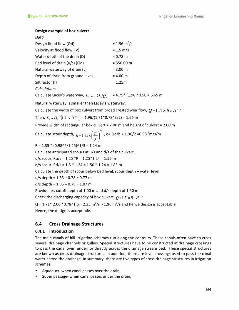
█ Egis Eau & RSPN/ BhWP Irrigation Engineering Manual
164
Designexampleofboxculvert
Data
Designfloodflow(Qd) =1.96m3/s
Velocityatfloodflow(V) =1.5m/s
Waterdepthofthedrain(D) =0.78m
Bedlevelofdrain(u/s)(Eld) =550.00m
Naturalwaterwayofdrain(L) =3.00m
Depthofdrainfromgroundlevel =4.00m
Siltfactor(f) =1.25m
Calculations
CalculateLacey’swaterway,db QL 75.4= =4.75*(1.96)^0.50=6.65m
NaturalwaterwayissmallerthanLacey’swaterway.
Calculatethewidthofboxculvertfrombroadcrestedweirflow, 2/371.1 HBQ ××=
Then, ( )2/371.1/ HQL db ×= =1.96/(1.71*0.78^3/2)=1.66m
Providewidthofrectangularboxculvert=2.00mandheightofculvert=2.00m
Calculatescourdepth,3/1
2
35.1 ⎟⎟⎠
⎞⎜⎜⎝
⎛×=
f
qR ,q=Qd/b=1.96/2=0.98
3m/s/m
R=1.35*(0.98^2/1.25)^1/3=1.24m
Calculateanticipatedscoursatu/sandd/softheculvert,
u/sscour,Ru/s=1.25*R=1.25*1.24=1.55m
d/sscour.Rd/s=1.5*1.24=1.50*1.24=1.85m
Calculatethedepthofscourbelowbedlevel,scourdepth–waterlevel
u/sdepth=1.55–0.78=0.77m
d/sdepth=1.85–0.78=1.07m
Provideu/scutoffdepthof1.00mandd/sdepthof1.50m
Checkthedischargingcapacityofboxculvert, 2/371.1 HBQ ××=
Q=1.71*2.00*0.78^1.5=2.35m3/s>1.96m
3/sandhencedesignisacceptable.
Hence,thedesignisacceptable.
6.4 CrossDrainageStructures
6.4.1 Introduction
Themaincanalsofhill irrigationschemesrunalongthecontours.Thesecanalsoftenhavetocross
severaldrainagechannelsorgullies.Specialstructureshavetobeconstructedatdrainagecrossings
topassthecanalover,under,ordirectlyacrossthedrainagestreambed.Thesespecialstructures
areknownascrossdrainagestructures.Inaddition,therearelevelcrossingsusedtopassthecanal
wateracrossthedrainage.Insummary,therearefivetypesofcrossdrainagestructuresinirrigation
schemes.
• Aqueduct-whencanalpassesoverthedrain,
• Superpassage-whencanalpassesunderthedrain,
█ Egis Eau & RSPN/ BhWP Irrigation Engineering Manual
165
• Siphon-shallowordeep-whencanalpassesunderthedrain,
• Drainculvert-whendrainpassesunderthecanal,and
• Levelcrossing-whencanalcrossesthedrainatthesamelevel
Traditional community-managed irrigation schemes have either level crossings or wooden log
aqueductstocrossthecanalthroughnaturaldrainage.InGovernment-assistedirrigationschemes,
aqueducts,superpassagesandsiphonsarecommonlyseeninBhutan.Inhillirrigationschemes,the
canalcanalsobepassedthroughtheHDPpipecrossing,whichislikeanaqueduct.
6.4.2 SelectionofCrossDrainageStructure
Theselectionofthetypeofthecrossdrainagestructureisthemostimportantaspectofthedesign.
Fivefactorsneedtobeconsideredinselectingthecrossdrainagestructureatagivenlocation:
• Topography,
• Structuralstability,
• Hydrauliccompatibility,
• Stabilityofdrainagestream/gully,and
• Cost
Topographymeanstheshapeofthegullyincrosssectionandinplan.Theshapeofthegullycross
sectionwilllargelydeterminethetypeofcrossdrainagestructureattheparticularlocation.
Differentcrossdrainagestructureshavedifferentstabilityrequirementsandtheselectiondepends
uponthestabilityconditionsofthatlocation.Forexample,deepsiphonsandaqueductsneedstable
banksforstructuralstability.Similarly,asuperpassagerequiresanon-erodingstreambed.
Hydrauliccompatibilitymeansavailabilityofadequatehydraulicheadtodrivethecanalflowacross
the cross drainage structure. In comparison to aqueducts and super passages, inverted siphons
requiresignificantheaddifference inthe inletandoutletofthestructure.Similarly,relativewater
levels of the canal and drainage channel also affect the selection of the type of cross drainage
structure.
Thestabilityofthedrainagestreamorgullyensuressafetyofthecrossdrainagestructure.Widening
gullies candestroycrossdrainagestructure suchasaqueducts, siphons, superpassages,and level
crossings.Deepeninggulliescanalsodestroystructuressuchassiphonsandsuperpassages.
When two ormore technically sound alternatives are available for crossing a drainage gully, the
selectioncanbebasedonthecostsofthedifferentalternatives.Thecostsofallappertainingworks
such as increased length of canal, downstream protection, covered etc must be included in
calculatingthecostsofdifferentalternatives.
These five factors must be jointly considered when selecting the type of cross-drainage works
suitableforanygivenlocation. Atypical layoutfortheselectionofthecrossdrainagestructureis
illustratedhere(Figure6-19).

█ Egis Eau & RSPN/ BhWP Irrigation Engineering Manual
166
Figure6-19TributaryRiverCrossingOptions

█ Egis Eau & RSPN/ BhWP Irrigation Engineering Manual
167
6.4.3 DesignConsiderations
DesignFlood
The design flood discharge for the design of a cross drainage structure is assessed following
ungaugedcatchmentfloodflowassessmentdescribedinChapter-3ofthismanual. Insmalldrains,
thefloodreturnperiodmaybeconsideredas5to10years.Foraqueducts,a10yearreturnperiodis
essential while for super passages, siphons, and culverts, a 5 year return period is adequate.
PunakhaValleyDevelopmentProjectManual 1992 suggests a 10 year returnperiod flood for the
designfloodofcrossdrainagestructures.
WaterwayoftheDrain
Thewaterwayof thedrain isessential tocalculate inorder toavoidconstrictionof the floodflow
duetotheconstructionofthestructure.Inhillsandmountains,thewaterwayisprovidedwithinthe
existingdefinedbanksoftheriverordrain. Inplainareas,Lacey’swaterwaymaybeappropriate;
QP 75.4= where,Qisthedesignflooddischargeofthedrainorriver.
ContractionandExpansionofWaterway
Thecontractionandexpansionofthewaterwayofthedrainagechannelshouldbesmoothinorder
tominimizethelossofheadtherein.Contractionshouldnotexceed20%fordrains.Thetransitions
oftheaqueduct,siphon,andculvertbarrelshouldnotbesteeperthan2:1incontractionand3:1in
expansion.ThetransitionsaredesignedonthebasisofMitra’shyperbolictransitionequation:
( )fnnf
ffn
xBBXBL
LBBB
−−×
××=
Where,Bxisthebedwidthatanydistancexfromtheflumedsection,
Bnisthebedwidthofnormalcanalsection,
Bfisthebedwidthofflumedcanalsection,
Lfisthelengthoftransition,
HeadLossthroughStructure
The lossofheadacrossthestructurealsogovernsthechoiceofthestructure.Adequatehydraulic
headdrives thecanal flowacross thedrainagestructure.Aqueductsandsuperpassageshave less
headlosswhilesiphonsrequirehigherheaddifferencebetweentheirinletandoutlet.Thevelocity
throughthebarrelofasiphonor intheflumesectionofanaqueduct is limitedto2to3m/s.The
lossofheadatcontractionandexpansionoftheaqueductisassessedasfollows:
Lossofheadincontraction,⎟⎟⎠
⎞⎜⎜⎝
⎛ −=
g
vvhc
220.0
2
122
Lossofheadinexpansion,⎟⎟
⎠
⎞
⎜⎜
⎝
⎛ −=
g
vvhe
230.0
2
432
Where,V1,andV4arevelocitiesattheentryandexitcanalsections,V2,andV3arethevelocitiesat
thecontractionandexpansionflumesectionsrespectively.Forsmallcanals,theentryandexitloss
ofanaqueductisalsocalculatedas:

█ Egis Eau & RSPN/ BhWP Irrigation Engineering Manual
168
⎟⎟
⎠
⎞
⎜⎜
⎝
⎛ −=
g
vvh cf
f2
50.1
22
Where,VfandVcarevelocitiesofflumeandcanalsectionsrespectively.
ThelossofleadthroughsiphonbarrelisassessedbyUnwin’sformula:
g
V
g
V
R
Lffh
a
221
22
21−⎥
⎦
⎤⎢⎣
⎡×++=
Where,f1isthecoefficientofheadlossatentryanddependsupontheshapeofentry.Forunshaped
mouthf1=0.505andforbellmouthentryf1=0.08.
f2isthecoefficientofheadlossthroughthebarrelduetosurfacefriction, ⎟⎠
⎞⎜⎝
⎛+=R
baf 1
2
aandbarethecoefficientsdependinguponthematerialofbarrelconstruction;arangesfrom
0.032to0.010andbrangesfrom0.025to0.25.
Listhelengthofbarrelinm,
Visthevelocityofflowthroughbarrelinm,
Vaisthevelocityofapproachandisoftenneglectedinm/s,and
Risthehydraulicradiusofthebarrel
6.4.4 DesignofAqueduct
DesignConcept
Aqueducts areusedwhere canal crossesoverdeeply incised streamsordrains. Thereare various
typesof aqueductsdependingupon the constructionmaterial. Stonemasonrywalls and concrete
flumeaqueductsarethemostcommonlyusedaqueducts(Figure 6-20).Inaddition,HDPEpipeson
woodenbeamsorgalvanizedcablesarealsousedinhillsandmountains.Thebasicconsiderationsin
thedesignofanaqueductare:
• HFLofdrainorstreamshouldbesufficientlybelowthebedlevelofthecanal;
• Banksofthedrainshouldbestable;
• Forsmallirrigationschemes,thespanoftheaqueductshouldbelimitedto10m;
• Watervelocitiesintheflumeshouldbefrom1.0to1.5m/s
Figure6-20Typicalaqueducts

█ Egis Eau & RSPN/ BhWP Irrigation Engineering Manual
169
AdvantagesofAqueduct
• Minimumheadloss,
• Safeagainsthydrologicaluncertainties,
• Noerosionproblemifbuiltonstablefoundations,and
• Tobeusedforpedestrianwalkway
DisadvantagesofAqueduct
• Difficultconstructionincaseofdeepgullies,
• Foundationerosionincaseofshallowandwidegullies,
DesignProcedures
i. CalculatedesignflooddischargeofthedrainanditsHFL,
ii. Establishlevelsanddimensionsofthecanals,
iii. Establishlevelsandwaterwayofdrain,
iv. Fixthespanofaqueduct,
v. Designflumesection,
vi. Fixdimensionsofflumeandtransitions,
vii. Calculatethelossesintheflumeandtransitions
viii. Checkavailableheadatupstreamanddownstreamofthestructure,and
ix. Carryoutstructuraldesignwithsizingofductsection,piersandabutments
The design sketch of an aqueduct is presented in Figure 6-21 .
DesignExampleofRCCAqueduct
Canaldata:
Discharge(Q)=0.05m3/s
Bedwidth(B)=0.30m
Sideslope(m)=1:1
Waterdepth(d)=0.25m
Freeboard(Fb)=0.15
Draindata:
Catchmentarea(CA)=4sqkm
Flooddischarge(Qd)=40m3/s
Bankheight(hb)=5m
Highflooddepth(HFL)=3m
Naturalwaterway(L)=8m
Calculations:
i. Designflumesection
Providewaterdepthofflumesameasofcanaldepth(Hf)=0.25m
Assumevelocityofflowatflume(Vf)be0.75m/s

█ Egis Eau & RSPN/ BhWP Irrigation Engineering Manual
170
Thenwidthofflumesection=Q/Hf*Vf=0.267m
Adoptbedwidthofflume(Bf)=0.30m
TakeManning’sroughnesscoefficient(n)=0.02
Adoptslopeofflume(S)=1/200
Areaofflowatflume(Af)=Bf*Hf=0.30*0.25=0.075m2
Wetterperimeter(Pf)=Bf+2Hf=0.80m
Hydraulicradius(Rf)=Af/Pf=0.075/0.80=0.094m
Velocityofflow(Vf)=1/n*Rf^2/3*Sf^1/2=0.094^0.0667*(1/200)^0.50/0.02=0.73m/s
Discharge through flume (Qf) = Vf * Af = 0.73 * 0.075 = 0.055m3/swhich is greater than design
discharge(0.05m3/s),
Froudenumber(Fr)=Vf/(g*hf)1/2=0.466whichislessthan0.60andmaintainssub-criticalflowand
hencedesignisacceptable.
Figure6-21Designsketchofaqueduct
ii. Fixflumedimensions
Forsmalldischargeprovidelengthofcontractionandexpansiontransitions=1m
Lengthofflume=clearspanofaqueduct=8m
Takefreeboardforflumesection(Fb)=0.15m
Heightofductwall(Hf)=0.25+0.15=0.40m
Widthofbeam(Bq)=½ofdepth=0.20m,takewidthas0.25m
Assumethicknessofslab(ts)=100mm
Theoveralldepthofaqueductbeam(Dq)=Hf+Fb+ts=0.25+0.15+0.10=0.50m
█ Egis Eau & RSPN/ BhWP Irrigation Engineering Manual
171
iii. Calculationoflosses
Frictionlossattheflume(hf)=slopeofflumexlengthofflume=1/200*8=0.04m
Entryandexitloss⎟⎟
⎠
⎞
⎜⎜
⎝
⎛ −=
g
vvh cf
e2
50.1
22
FlumevelocityVf=0.73m/s
Canalvelocity=Q/A=0.05/(0.30*0.25+1*0.25^2)=0.364m/s
he=1.5(0.73^2-0.364^2)/2*9.81=0.0306m
Totalloss=hf+he=0.04+0.0306=0.070m
Thewaterlevelatthedownstreamendofaqueductshouldbeabout10cmbelowthewaterlevelof
theupstreamcanalwaterlevel.
iv. Structuraldesignofaqueduct
Thestructuraldesignofaqueductinvolvesthedesignofbaseslab,sidebeams,andabutmentwalls.
Designdata:
Spanofaqueduct=8m
Widthofcanal=0.30m
Widthofductsection=0.30m
Widthofsidebeam(bs)=0.25m
Depthofwater=Hf=0.25m
Freeboard=0.15m
Concretetype=M20
Densityofconcrete=24kN/mm2
Permissiblereinforcementstressincompression(pbc)=7.0N/mm2
Permissiblereinforcementstressintension(pst)=230N/mm2
Maximumshearstress(qcmax)=230N/mm2
TensileforceforReinforcementFe415(fst)=230N/mm2
Allowablebondstress(qbs)=1.12N/mm2
Densityofwater(gw)=10.0kN/mm3
Designofbaseslab:
Thicknessofslab=assumeas100mm
Deadloadofslab(qd)=24=0.10*1=2.4kN/mfor1mwidesection
Imposedloadduetowater(qw)=0.40*10.0=4.00kN/m
Totalloadonslab(q)=2.40+4.00=6.40kN/m
Effectivespanofslab(L)=0.30+0.25/2+0.25/2=0.55m
Maxbendingmomentonslab(Ms)=qL2/8=6.40*0.55^2/8=0.242kNm
Maxreactionatthebeam(Rs)=qL/2=6.40*0.55/2=1.76kN
Maxshearforce(F)=Rs=1.76kN
Calculateslabthickness(d)Ms=bd2;d=(Mr/Rb)^1/2=(0.242*1000/0.91)^0.5=16.31mm
Assumeslabcoveras=50mm

█ Egis Eau & RSPN/ BhWP Irrigation Engineering Manual
172
Totalslabthicknesswith10mmallowance(t)=16.31+50+10=76.31mm
Actualeffectivethicknessofslab(teff)=100-60=40mm
Steelreinforcementforslab(Ast)=Ms/pst*jd=(0.242*1000*1000)/(230*40*0.91)=29.09mm2
Minreinforcementrequired=0.25%ofareaofconcrete=250mm2
Provide12mmdiabars@200mmc/c=Ast’=339mm2
Check for shear stress (qv) = F/bd = (1.738*1000)/(1000*40)= 0.043N/mm2< allowable value of
1.80N/mm2
Distributionsteelontop=0.10%ofareaofconcreteor20%ofAst=100mm2
Provide10mmdiabars@150mmc/c=237mm2
Designofbeam:
Beandeadload(qb)=24*0.25*0.5=3.0kN/m
Deadloadofslab(qs)=0.50*0.30*100*24/1000=0.36kN/m
Weightofwater(qw)=0.50*0.30*0.25*10=0.375kN/m
Totalloadonbeam(q)=6.0+0.36+0.368=3.735kN/m
Effectivespanofbeam(Leff)=8.0+2*0.30=8.60m
Maxbendingmomentofbeam(Mb)=qL2/8=3.735*8.60^2/8=34.53kNm
Maxreactionatthebeam(Rs)=qL/2=3.728*8.60/2=16.06kN
Maxshearforce(F)=Rs=16.06kN
Calculateslabthickness(d)Mb=bd2;d=(Mb/Rb)^1/2=(34.53*1000/0.91)^0.5=194.80mm
Assumeslabcoveras=50mm
Totalslabthicknesswith10mmallowance(t)=194.80+50+10=254.80mm
Actualeffectivethicknessofslab(teff)=500-60=440mm
Steelreinforcementforslab(Ast)=Ms/pst*jd=(34.53*1000*1000)/(230*440*0.91)=377.44mm2
Provide2-20mmdiabars=Ast’=628mm2
Checkforbarspacing@minbardiameterorsizeofcoarseaggregateplus5mm=20mmor25mm
Actualbarspacing=beamwidth–twicecover–stirrups–noofbars=250-2*50-10-2*20=90mm>
25mm,henceOK
Checkminreinforcement=0.25%ofconcretearea=0.25*0.25*0.50*1000*1000=312.50mm2,OK
Check for shear stress (qv) = F/bd = (16.06*1000)/(250*440)= 0.146N/mm2 < allowable value of
1.80N/mm2
Distributionsteelontop=0.15%ofareaofconcreteor20%ofAst=187.50mm2
Provide2-12mmdiabars=226mm2
Sidereinforcementonbeam=0.15%ofareaofconcrete=187.50mm2
Provide2-12mmdiabars=226mm2
Thedesignofabutmentwallsiscarriedoutsimilartothedesignofretainingwall.
Hencedesigniscomplete.
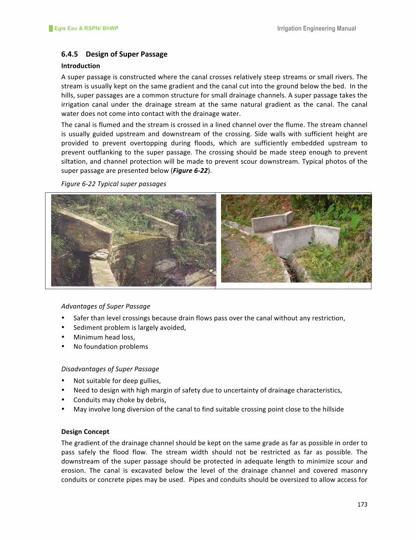
█ Egis Eau & RSPN/ BhWP Irrigation Engineering Manual
173
6.4.5 DesignofSuperPassage
Introduction
Asuperpassageisconstructedwherethecanalcrossesrelativelysteepstreamsorsmallrivers.The
streamisusuallykeptonthesamegradientandthecanalcutintothegroundbelowthebed.Inthe
hills,superpassagesareacommonstructureforsmalldrainagechannels.Asuperpassagetakesthe
irrigation canal under the drainage stream at the same natural gradient as the canal. The canal
waterdoesnotcomeintocontactwiththedrainagewater.
Thecanalisflumedandthestreamiscrossedinalinedchannelovertheflume.Thestreamchannel
is usually guided upstream and downstream of the crossing. Sidewallswith sufficient height are
provided to prevent overtopping during floods, which are sufficiently embedded upstream to
prevent outflanking to the super passage. The crossing should bemade steep enough to prevent
siltation,andchannelprotectionwillbemadetopreventscourdownstream.Typicalphotosofthe
superpassagearepresentedbelow(Figure6-22).
Figure6-22Typicalsuperpassages
AdvantagesofSuperPassage
• Saferthanlevelcrossingsbecausedrainflowspassoverthecanalwithoutanyrestriction,
• Sedimentproblemislargelyavoided,
• Minimumheadloss,
• Nofoundationproblems
DisadvantagesofSuperPassage
• Notsuitablefordeepgullies,
• Needtodesignwithhighmarginofsafetyduetouncertaintyofdrainagecharacteristics,
• Conduitsmaychokebydebris,
• Mayinvolvelongdiversionofthecanaltofindsuitablecrossingpointclosetothehillside
DesignConcept
Thegradientofthedrainagechannelshouldbekeptonthesamegradeasfaraspossibleinorderto
pass safely the flood flow. The stream width should not be restricted as far as possible. The
downstreamof the superpassage shouldbeprotected in adequate length tominimize scour and
erosion. The canal is excavated below the level of the drainage channel and covered masonry
conduitsorconcretepipesmaybeused.Pipesandconduitsshouldbeoversizedtoallowaccessfor

█ Egis Eau & RSPN/ BhWP Irrigation Engineering Manual
174
cleaning out debris and sediment. The sidewalls of the super passage should be high enough to
allowfreeboardtohighfloodlevelofthedrainagechannel.
DesignProcedure
Thedesignprocedureof the super passage involves the assessmentof thedesign flood flowand
calculationofthesizeofdrainagechanneloverthecanal.
i. Assessdesignflooddischargeofthedrainbasedoncatchmentcharacteristics,
ii. Designlinedcanalsectionorflumesection,
iii. DesigndrainsectionusingManning’sequationtomatchwithdesignfloodflow,
2/13/21SR
nV =
WhereVisthevelocityofdrainageflow,
nistheroughnesscoefficientdependsuponthetypedrainagechannel,
Risthehydraulicradiusofthedrainagesection,
Sisthewatersurfaceslopeofthedrainageflow
iv. CalculateFroudenumber
gD
VF =
v. Assesstheenergydissipationrequiredatthedownstreamofthesuperpassage(Figure6-23)
DesignExampleofSuperPassage
CanalData:
Designdischarge(Qd): 50lps
Bedwidth(B): 0.30m
Waterdepth(d): 0.25m
Freeboard(Fb): 0.15m
Bedslope(S): 1/500
Canalsideslope(m): 1:1
Roughnesscoefficient(n): 0.025
DrainData:
Designflooddischargeat5yearsreturnperiod(Qf):5m3/s
Widthofdrain(w): 5m
Slopeofdrain(Sd): 1/20
Waterdepth(d): 0.40m
Roughnesscoefficient(n): 0.05

█ Egis Eau & RSPN/ BhWP Irrigation Engineering Manual
175
Figure6-23Designsketchofsuperpassage
Designoflinedcanalsection:
AdoptB/Dratioas: 1
Bedwidth(B): 0.35m
Waterdepth(d): 0.35m
Freeboard(Fb): 0.15m
Bedslope(S): 1/500
Canalsideslope(m): 0(rectangularsection)
Roughnesscoefficient(n): 0.020
Areaofflow(A)=B*D 0.12m2
Wettedperimeter(P)=B+2*D 1.05m
Hydraulicradius(R)=A/P 0.12m
Velocityofwater(v)=1/n*R^2/3*S^1/2 0.53m/s
Discharge(Q)=A*V 0.07m3/s;hence>0.05m
3/s,OK
Designofsuperpassage(linedsection):
Adoptwidthofpassage(W): 5m(sameasdrainwidth)
Providedepthofwater(d): 0.40m
Freeboard(Fb): 0.20m
Areaofflow(A)=B*D 2.0m2
Wettedperimeter(P)=B+2*D 5.80m
Hydraulicradius(R)=A/P 0.34m
Velocityofwater(v)=1/n*R^2/3*S^1/2 3.48m/s
Discharge(Q)=A*V=2*3.48= 6.95m3/shence>5m
3/s,OK
ThevelocityissupercriticalasFroudenumber
gD
VF =
=1.76

█ Egis Eau & RSPN/ BhWP Irrigation Engineering Manual
176
AsFroudenumberis1.76andflowissupercritical,itisessentialtodissipateenergydownstreamof
the super passage by providing protection works. In hilly areas where hard rock may exist
downstreamofthesuperpassage,protectionworksmaynotbeneeded.
6.4.6 DesignofCanalSiphon
Introduction
Invertedsiphonsareusedtocrossthedrainagechannelbyacanal.Therearetwotypesofsiphons:
• Shallowsiphontocrossshallowandwideriverwithlittlepressurehead,and
• Deepsiphontocrossdeepriverwithhighpressurehead
Shallowsiphon:Shallowsiphonsaredesignedsothattheriverordrainiskeptonthesamegradient
and the canal flows in a conduit under the river bed. Small siphons are often designed using
concretepipeswhilelargesiphonsaredesignedusingconcretebarrel.Adequatevelocityshouldbe
providedtopreventsiltationat lowflows.Forsmall irrigationcanals,adroptypeinletcanalsobe
provided.Topreventchokingfromfloatingdebris,atrashrackisprovidedupstreamoftheinverted
siphon.
Figure6-24Typicalshallowanddeepsiphons
DeepSiphon:Deepsiphonsareusedinhillschemestocrosstheriverindeepvalleys.Thesiphons
are takendownthevalley side,anchoredbyblocks,and thencrossed the riveron theshort span
bridge.Duetohighpressuresthesiphonsareusuallymadeofsteelpipes(Figure6-24).
Advantagesofsiphon
• Preferredinwidestreams,
• Nofoundationproblems,
• Drainageflowdoesnotaffectstructuralsafety
Disadvantagesofsiphon
• Significantheadloss,
• Pipemaychokewithsedimentanddebris
DesignConceptofShallowSiphon
Atrashrackscreenisrequiredattheupstreamentryofthesiphon.Someformofprotectionisalso
required above the pipe line in the river bed. Adequate submergence should be provided to the

█ Egis Eau & RSPN/ BhWP Irrigation Engineering Manual
177
pipes below the canalwater levels at the inlet and outlet (0.25m or half of the pipe diameter).
Sallowsiphonshouldbecheckedforflotation,whenemptyinhighgroundwaterareas.
Designprocedure
The design procedure of the shallow siphon includes the calculation of barrel size to meet the
requirementofflowandcalculationofheadlossthroughthebarrel.
i. Assessfloodflowinthedrainagechannel,
ii. Calculatewaterwayofdrainagechannel, QPw 74.4=
iii. Assumevelocityofflowinthebarreltopreventsiltinginsidethebarrel,
iv. Calculatethesizeofbarrel(pipeorconduit),
v. Calculateheadlossintheconduitbarrelusingfollowingformula:
FrictionheadlossgD
fLvh f
2
2
= orfromnomogramofconcretepipe(Figure5-10),
Where,hfistheheadlossinm,
fisthefrictionalcoefficientofthepipe,whichiscalculatedbyMoodyequation,
Listhelengthofthepipeinm,
Visthevelocityofwaterinthepipeinm/s,V=Q/A
gistheaccelerationduetogravityinm/sec2,
Disthediameterofpipeinm,
Qisthedischargeofthepipeinm3/s,
Aisthecrosssectionalareaofthepipeinm2,
Entryandexitheadloss⎟⎟
⎠
⎞
⎜⎜
⎝
⎛ −=
g
vvh c
e2
50.1
22
Bendlossg
Vkhb2
2
=
Wherekisthecoefficientdependingupontheangleofbendsandranges0.10to0.20
Thetrashrack(Figure6-25)lossattheinletofthesiphon(hr)=3Sinδ(s/b)4/3*V
2/2g
Where,Visthevelocityinsiphonbarrel,Sisthetrashrackbarthicknessinmmandbisthespacing
ofrackbarinmm
Figure6-25Designsketchoftrashrack
Forsmallsiphonconduittrashrackloss(ht)istakenas0.10m.
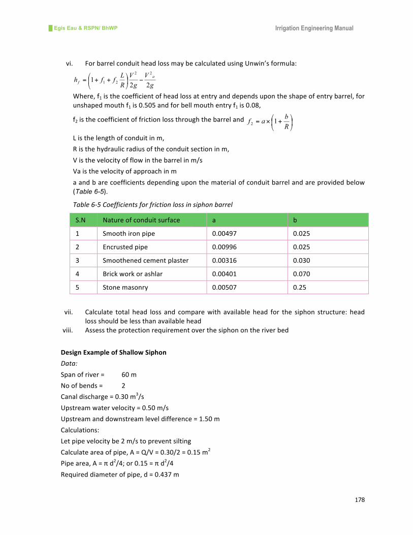
█ Egis Eau & RSPN/ BhWP Irrigation Engineering Manual
178
vi. ForbarrelconduitheadlossmaybecalculatedusingUnwin’sformula:
g
V
g
V
R
Lffh
a
f22
1
22
21−⎟
⎠
⎞⎜⎝
⎛++=
Where,f1isthecoefficientofheadlossatentryanddependsupontheshapeofentrybarrel,for
unshapedmouthf1is0.505andforbellmouthentryf1is0.08,
f2isthecoefficientoffrictionlossthroughthebarreland ⎟⎠
⎞⎜⎝
⎛+×=R
baf 1
2
Listhelengthofconduitinm,
Risthehydraulicradiusoftheconduitsectioninm,
Visthevelocityofflowinthebarrelinm/s
Vaisthevelocityofapproachinm
aandbarecoefficientsdependinguponthematerialofconduitbarrelandareprovidedbelow
(Table 6-5).
Table6-5Coefficientsforfrictionlossinsiphonbarrel
S.N Natureofconduitsurface a b
1 Smoothironpipe 0.00497 0.025
2 Encrustedpipe 0.00996 0.025
3 Smoothenedcementplaster 0.00316 0.030
4 Brickworkorashlar 0.00401 0.070
5 Stonemasonry 0.00507 0.25
vii. Calculate total head loss and comparewith available head for the siphon structure: head
lossshouldbelessthanavailablehead
viii. Assesstheprotectionrequirementoverthesiphonontheriverbed
DesignExampleofShallowSiphon
Data:
Spanofriver= 60m
Noofbends= 2
Canaldischarge=0.30m3/s
Upstreamwatervelocity=0.50m/s
Upstreamanddownstreamleveldifference=1.50m
Calculations:
Letpipevelocitybe2m/stopreventsilting
Calculateareaofpipe,A=Q/V=0.30/2=0.15m2
Pipearea,A=πd2/4;or0.15=πd
2/4
Requireddiameterofpipe,d=0.437m

█ Egis Eau & RSPN/ BhWP Irrigation Engineering Manual
179
This diameter is not available commercially and need to select 600mm diameter pipe with A =
0.283m2
The velocity ofwater at pipe, V =Q/A = 0.15/0.283 = 1.06m/swhich is insufficient to flush the
sedimentinsidethepipe,henceselectpipediameterof450mm,
Areaofpipe,A=0.158m2andvelocityinpipeV=Q/A=0.30/0.158=1.90m/swhichisacceptable.
Calculatefrictionlossinpipe;forconcretepipewithK=0.3mmheadlossfromchart=0.33m/100m,
Lossofheadfor60mlengthhf=0.33/100*60=0.55m
Calculateentryandexitloss⎟⎟
⎠
⎞
⎜⎜
⎝
⎛ −=
g
vvh cf
e2
50.1
22
he=1.5(1.9^2-0.5^2)/2*9.81=0.26m
Bendlosshb=kV2/2g=2*0.10*1.90^2/19.62=0.036m
Taketrashrackloss=0.10m
Totalloss=0.55+0.26+0.04+0.10=0.95m
Theheadavailableis1.5mandrequiredheadlossisonly0.95m,hencethedesignisacceptable.
DesignConceptofDeepSiphon
Deepsiphonsareusuallyconstructedofsteelpipesduetohighpressure.Velocitiesandheadlosses
arealsohigh.Thebridgeisoftenasuspensiontypewithapipeheldinwireslingsbelowthecable.
ThebridgecanalsobeofsimplysupportedRCCpierandabutments.Pipesiphonsofupto40mlong
withmaximumpressureheadof50mandasuspendedspanofupto40mhavebeenconstructed.
Atthe inletchamber,atrashscreen isrequiredtoreduceblockageanddroptype inletandoutlet
boxesareadequateforsmallirrigationcanals.Thedesignvelocityinthepipeshouldbeintherange
of1.5mto3m/stopreventsiltation.Adequatesubmergenceshouldalsobeprovidedattheinlet
andoutletanddrainvalveshouldalsobeprovidedatthelowestpointofthesiphontowashout.In
addition, adequate anchorage should be provided to support pipeline across the valley. to resist
trustofthepipeflowattheslopes.
Thedesignprocedureofdeepsiphonissameasforshallowsiphons.

█ Egis Eau & RSPN/ BhWP Irrigation Engineering Manual
180
Figure6-26Typicaldeepsiphon

█ Egis Eau & RSPN/ BhWP Irrigation Engineering Manual
181
6.4.7 HighDensityPolythene(HDP)PipeCrossing
DesignConcept
HDP pipes are extensively used in small hill irrigation schemes both for crossing the drainage
channel and as a conveyance canal where an open canal section is not suitable due to difficult
terrain. MajorbenefitsofHDPpipesarethattheyareeasytotransport,haveaflexiblestructure,
andaresuitable inremoteareas.However,skilledmanpower isnecessarytoerect thepipe joints
andsuspendedcables.ThedesignofHDPpipesconsistsoftwocomponents:
• HydraulicdesignofHDPpipe;and
• Structuraldesignofcablesuspension
ThehydraulicdesignoftheHDPpipecrossingconsistsofthecalculationofthesizeofthepipe,its
length,andassessmentofheadlossinthestructure.Inadditiontothefrictionlossofthepipeentry
andexitloss,bendlossandjointlossshouldbeassessed.Thelengthofthepipedependsuponthe
topographyofthedrainageuptostablebanks.
The structural design of a HDP crossing consists of the calculation of saddle difference, cable
inclination,tension incables,and loads.The loads incableareofcable itself,pipewithfullwater,
andwindload.
Figure6-27TypicalphotosofHDPEpipecrossing
Designprocedure
i. CalculatethelengthoftheHDPpipebasedonthetopographyofthesite,
ii. Calculatethesizeofthepipebasedontherequireddischargetopassandlimitingvelocityin
thepipe,
iii. Calculatetheheadlossinpipefromformula:
Headlossfromnomogramorfromtableprovidedbymanufacturer,
Entryandexitlossisassessedas,He=1.5*(V2pipe-V
2canal)/2g
Where,Vpipeisvelocityofwaterinpipeinm/s
Vcanalisvelocityofcanalattheinletinm/s
Jointlossisassessedas25%offrictionlossforeachjoint.
ThebendlossiscalculatedasHb=k*Vpipe2/2g,
Where,kisbendcoefficientandrangesfrom0.10to0.20
Vpipeisvelocityofwaterinpipeinm/s
Thetrashracklossistakenas0.10forsmallirrigationschemes.

█ Egis Eau & RSPN/ BhWP Irrigation Engineering Manual
182
iv. Calculatethetotalheadlossandcomparewithavailableheadofthesite,
v. Structuraldesignofsuspensioncable
vi. Selectthesizeofcablebasedonstandardspecifications,
vii. Calculatecablelengthfromformula:
Cablelength=1.1xspan+backstaylength+6m
Wherebackstaylengthisthecablelengthbetweensaddlecenterandcenterofanchorage
blockasperfoundationconsideration,
viii. Calculatehostingsag
Thecrosssectionalareaofthecableistheactualareaofthewirewithoutcountingthevoidspace
betweenwires.Thevaluefortheareacanbeestimatedfromtheinformationonthecableweight
and specific gravity (7.843 t/m3) for steel in the wire. The designer should obtain values of E
(modulusofelasticity)andcross-sectionalareafrommanufacturerordesigner’sbestjudgmenthas
tobeused.
DesignExampleofHDPPipeCrossing
Designdata
Dischargetobepassedthroughthepipe=0.05m3/s
Spanofcrossing=20.0m
Leveldifferencebetweenthepipeinletandoutlet=2.0m
TotallengthofHDPpiperequiredfrominletpointtooutletpoint=50.0m
VelocityofflowinopenchannelneartheinletpointofHDPpipe=0.75m/s
Maximumallowablevelocityinpipe<3m/s
Calculations:
Weknow,Q=V.A,A=Q/V,
From standard nomogram (Figure 5-11) for Q=0.05 m3/s, head loss = HL (m/100m) =
0.88/100=0.0088m,andV=1.59m/s
Flowareaofpipe,A=Q/V=0.05/1.59=0.03145m2
Internaldiameterofpipe,Ø=(4*A/3.14)1/2=(4*0.03145/3.14)1/2=0.200m
Chose225mmouterdiameterHDPpipefromseriesIII(datafromHDPpipemanufacturer)
Availableinternaldiameterofpipe=225-2*12.2=200.6mm,whichisclosetochosenØ=200mm
Hence,OK
Calculationoflosses
Headlossduetofrictionin50.0mlongpipe(hf)=50*HL=50*0.0088=0.44m
Entryandexitloss(he)=1.5*(V2pipe-V2canal)/2g
he=1.5*(1.592-0.752)/2*9.81=0.15m
Trashrackloss(ht)=0.10m
Jointlossisestimatedasthefrictionlossinpipelengthequivalentto0.25mperjoint
hj=0.25*(50m/5-1)=3.125m(consideringlengthofonepipetobe5m)
Therefore,jointloss=0.0088*3.125=0.0275m
Bendloss(hb)=k*V2pipe/2g,where(k=0.10)
█ Egis Eau & RSPN/ BhWP Irrigation Engineering Manual
183
hb=0.10*1.592/2*9.81=0.0123mperbend
Assumingmaximum4bendsinthiscaseweget,bendloss=0.0123*4=0.052m
Totalloss=0.44+0.15+0.10+0.0275+0.052=0.77m
Leveldifferencebetweeninletandoutletis2m
Hence,thedesignofthepipeisOK
Structural design of cable suspension is carried out on standard manufacturers design and
specifications.
6.5 SedimentControlStructures
6.5.1 Introduction
Most rivers and streams of Bhutan carry large quantities of sediment, especially during the
monsoon.Deforestation,soilerosion,landslidesandnaturalgeologicalprocessescontributetothe
high sediment load of mountain rivers. These rivers carry sediment particles ranging from large
boulderstofineclaydependinguponthestagesoftherivers.Duringthemonsoon,floodriversmay
carrylargeboulderstofineclay,andduringnormalflowtheycarrygraveltofineclay.Riverborne
sedimentaffectirrigationcanalsbyreducingcapacity,blockingcanals,andnegativelyaffectingcrop
yields. Hence, sediment entry into irrigation canals can be minimized with the construction of
precautionary structures. The sediment removal structures appropriate for hilly terrain are gravel
trapsandsettlingbasins.
Thechoiceofgraveltraporsettlingbasindependsonvariousfactorssuchasavailabilityofsuitable
location, economyof the structure, remoteness of the location, and farmer’s capacity to operate
andmaintainthestructure.
6.5.2 GravelTraps
DesignConcept
Agraveltrapbasicallyconsistsofadeepwellbuiltinstonemasonryorconcreteimmediatelyafter
theintake. It isdesignedtotrapsedimentconsistingofparticlesgreaterthanthesizeofgravel(2
mm).Thedesignprincipleistoreducetheflowvelocityinthewelltoallowthesedimenttosettleon
the floor. In small irrigation schemes in the hills, a gravel trap behind the intake is provided to
exclude the gravel from entering into the canal. The design of gravel traps differs from that of
settlingbasinsbecausetheformerhandlescoarsematerialwhichentersnearthebed,ratherthan
suspendedmaterialwhichhas tobesettledthroughthedepth.The flowvelocities insidethewell
mayneedtobeloweredto0.30meterpersecondtotrap2mmsizeparticles.Table6-6indicates
thenecessaryvelocitiesinthegraveltrapwhichwillpermittrappingofparticlesvaryinginsizefrom
100mmto2mm.
Table6-6Flowvelocitythroughgraveltrap
ParticleSize
mm
Nominalvelocity(m/s)for
depthsof
Designvelocity(m/s)
fordepthsof
3m 1.5m 3m 1.5m
100 4.0 3.5 2.0 1.7

█ Egis Eau & RSPN/ BhWP Irrigation Engineering Manual
184
ParticleSize
mm
Nominalvelocity(m/s)for
depthsof
Designvelocity(m/s)
fordepthsof
60 3.4 3.0 1.7 1.5
40 3.0 2.6 1.5 1.3
20 2.3 2.1 1.2 1.1
10 1.8 1.6 0.9 0.8
5 1.8 1.6 0.7 0.6
2 0.8 0.7 0.4 0.3
Graveltrapsmaybeemptiedbyhandorbyflushingandhencethewidthofagraveltrapmustbe
onemeter to allow formanual removalof sediment. The typical sketchof a gravel trap for small
irrigation schemes ispresented inFigure6-28. Theoverall sizeof thegravel trapdependson the
rateofaccumulationofgravelsediment,theintervalbetweenmanualcleaning,availablespaceand
costofthestructure.
Figure6-28Typicalgraveltrapstructure
DesignProcedure
i. Fixthesizeofsedimentparticlestoberemoved,
ii. Decidethesedimentconcentrationduringnormalflowoftheriver,
iii. Assessthelocationofthegraveltrapandavailableheadtoflushthesediment,
iv. Determinethestoragevolumeingraveltrapfromtheformula:
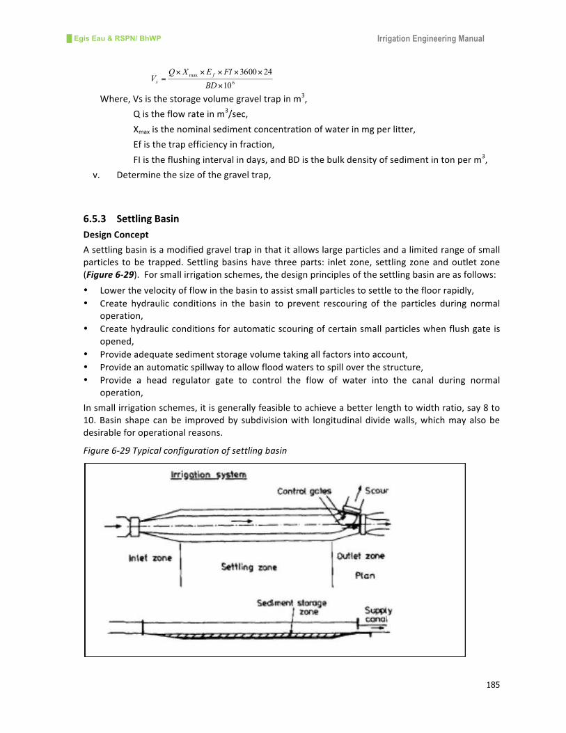
█ Egis Eau & RSPN/ BhWP Irrigation Engineering Manual
185
6
max
10
243600
×
×××××=
BD
FIEXQV
f
s
Where,Vsisthestoragevolumegraveltrapinm3,
Qistheflowrateinm3/sec,
Xmaxisthenominalsedimentconcentrationofwaterinmgperlitter,
Efisthetrapefficiencyinfraction,
FIistheflushingintervalindays,andBDisthebulkdensityofsedimentintonperm3,
v. Determinethesizeofthegraveltrap,
6.5.3 SettlingBasin
DesignConcept
Asettlingbasinisamodifiedgraveltrapinthatitallowslargeparticlesandalimitedrangeofsmall
particles tobe trapped. Settlingbasinshave threeparts: inlet zone, settling zoneandoutlet zone
(Figure6-29).Forsmallirrigationschemes,thedesignprinciplesofthesettlingbasinareasfollows:
• Lowerthevelocityofflowinthebasintoassistsmallparticlestosettletothefloorrapidly,
• Create hydraulic conditions in the basin to prevent rescouring of the particles during normal
operation,
• Createhydraulicconditionsforautomaticscouringofcertainsmallparticleswhenflushgateis
opened,
• Provideadequatesedimentstoragevolumetakingallfactorsintoaccount,
• Provideanautomaticspillwaytoallowfloodwaterstospilloverthestructure,
• Provide a head regulator gate to control the flow of water into the canal during normal
operation,
Insmallirrigationschemes,itisgenerallyfeasibletoachieveabetterlengthtowidthratio,say8to
10.Basin shapecanbe improvedby subdivisionwith longitudinaldividewalls,whichmayalsobe
desirableforoperationalreasons.
Figure6-29Typicalconfigurationofsettlingbasin
█ Egis Eau & RSPN/ BhWP Irrigation Engineering Manual
186
DesignProceduresofSettlingBasin
i. Fix thesmallestparticle thatwillbetrapped insidethestillingbasin (recommendedsize is
0.50mm),
ii. Fix the smallest particle that will be flushed automatically when flush gate is opened
(recommendedsizeis0.80mm),
iii. Usethenomogramtodeterminetheminimumsizeofthesettlingbasinrequired,
iv. Use nomogram to determine the minimum flow depth required in the settling basin to
preventrescourofthesmallestparticles,
v. Usenomogramtofixthescourvelocitynecessarytoflushsolidparticlesofsizefixedin(ii)
above,
vi. Determine the required scour slope necessary to generate velocity calculated in (v) from
Manning’sformula,
vii. Assumingstandardgatewidthdeterminethelevelofthesandsluicefloorbelowthelevelof
settlingbasinfloor,
viii. Computetheavailablesedimentstoragevolumeandadjustdimensionsofthesettlingbasin,
ix. Determinenecessarysilllevelattheheadregulatortocontroltheflowintothemaincanal
duringnormaloperation,
x. Determine the length and crest level of automatic side spill assuming flush gate is fully
closed,
xi. Determinetheexpectedflowintothemaincanalduringflood,
xii. Calculatethelengthofsidespillway,
xiii. Designtheflushoutcanal
DesignExampleofSettlingBasin
Data
Designdischarge(Q)=200l/s
Sizeofsmallestparticletobetrappedinsidethestillingbasin=0.50mm
Sizeofsmallestparticletobeflushedautomaticallywhengateisopened=0.80mm
Calculations
Usingnomogram(Figure 6-30)forparticlesizeof0.50mm,ratioofdischargetosurfacearea,Q/As=
0.017
ThensurfaceareaofbasinAs=Q/0.017=0.20/0.017=11.76m2
Takewidthofthebasin(B)=1.25m(recommendedas1mto1.5m)andlengthofthebasin(L)
L=10mwithbasinareaof12.50m2
Checkthelengthtowidthratio(L/W)=10/1.25=8whichisOK
Determineminimumflowdepth(dmin)topreventrescourofsmallestparticles=Q/(V*B)
Velocityofflowfor0.50mmparticlesfromnomogram(Figure 6-30)V=0.24m/s
Thenflowdepth(dmin)=0.20/(0.24*1.25)=0.67m
Calculatestoragevolume
6
max
10
243600
×
×××××=
BD
FIXQVs
η
Where, Xmax =900mg/l
η =0.90
█ Egis Eau & RSPN/ BhWP Irrigation Engineering Manual
187
FI =7daysandBD=2.0t/m3
Vs=0.20x900x0.90x7x3600x24/2x10^6=49m3
Storagedepth=Vs/areaofbasin=49/(10x1.25)=3.92mfor7daysflushing
Asthestoragedepthfor7daysflushingishigh,itisnecessarytoincreasethesizeofthebasin,
Letlengthofbasinbe=30mandwidthofbasinbe=2m
Minimumflowdepthrequiredtopreventrescourofsmallparticles=Q/(VxB)
Dmin=0.20/(0.24*2)=0.42m
ThestoragedepthDs=Vs/LB=49/(30x2)=0.82mfor7daysflushing
For particle size of 0.80 mm to be automatically flushed scour velocity from nomogram (Figure
6-31),Vsc=1.83m/s
Allowingscouringflow=1.25Qdesign,Qs=1.25x0.2=0.25m3/s
Scourflow/unitwidthqs=Qs/B=0.25/2=0.125m3/sperm
Scourdepthofflow,Ys=qs/Vsc=0.125/1.83=0.07m
MinimumbedsloperequiredtoflushthesedimentSc=(nxVsc)^2x(1/Ys)^4/3
Sc=(0.025x1.83)^2/(1/0.07)^4/3=0.075
Assuminga0.60mwidescourgatedischargeintensity,qg=Qs/Wg=0.25/0.60=0.42m3/sperm
Scourdepthatgate(Yg)=(qs/1.71)^2/3=(0.125/1.71)^(2/3)=0.39m
Depthofsluicebelowbasinfloor(dls)=Yg+0.05–Ys=0.39+0.05-0.07=0.37m
Adoptdepthofsluiceas0.40m
Designofsidespillway
Addextra50%dischargeindesigndischargeforflood(Qf)=1.5Qd=1.5x0.20=0.30m3/s
Dischargetobespilled(Qsp)=Qf-Qd=0.30-0.20=0.10m3/s
Take width of spillway as 2m and calculate head over the crest by sharp crested weir formula,
hsp=(Qsp/1.84xLsp)^3/2=(0.10/1.84*2)^3/2=0.09m
Assumefreeboardas0.11m
Duringfloodflowwaterdepthwillincreaseincanalandinbasinby:
(Qf/Qd)^0.60=dflood/ddesignthenfloodwaterdepth(df)=(0.30/0.20)^0.60x0.35=0.446m
Thedepthofwaterincanalwillriseby0.446-0.35=0.090m
Hence,spillweirheight=increaseddepthofwater+Fb=0.09+0.11=0.20m
Designofflushoutcanal
ScouringvelocityVsc=1.83m/sandQf=0.30m3/s
Theareaofflow,A=Qf/Vsc=0.30/1.83=0.164m2,
AdoptbedwidthofcanalaswidthofgateB=0.60m
Waterdepthincanal,D=A/B=0.164/0.60=0.27m
Takefreeboardas0.08mtotaldepthofcanalbe0.35m
Requiredslopeoftheflushingcanalisgivenby
Sf=(Vsc^2*n^2)(1/D)^4/3=(1.83x0.025)^2(1/0.27)^4/3=0.0065
Theslopeisabout1:155
Designisacceptable.
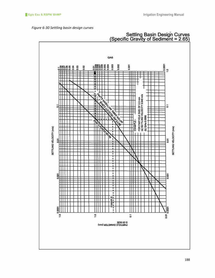
█ Egis Eau & RSPN/ BhWP Irrigation Engineering Manual
188
Figure6-30Settlingbasindesigncurves

█ Egis Eau & RSPN/ BhWP Irrigation Engineering Manual
189
Figure6-31Scouringvelocitiesforsandtrap
█ Egis Eau & RSPN/ BhWP Irrigation Engineering Manual
190
6.6 RetainingWalls
6.6.1 Introduction
Retainingwalls are the structuresnecessary toprotect the canal fromslippingor slidingalong its
alignment.Inhillirrigationschemes,retainingwallsareessentialwherecanalalignmentisnotstable
enoughduetouphill slidingordownhill slipping.Froma loadingpointofview,retainingwallsare
gravity,cantileverandcounter-fortretainingwalls.Ingravityretainingwalls,pressureactingonthe
wallisresistedwithitsweight,whilecantileverandcounter-fortretainingwallsresistpressurewith
bending actions. The most commonly used retaining walls are gravity walls which are classified
basedonthematerialsusedasfollows:
a) Masonryretainingwalls
Masonryretainingwallsarewidelyusedfornewconstructionofirrigationschemes.Theseretaining
wallsareeitherrandomrubblemasonryordressedstonemasonry.Sufficientweepholesshouldbe
providedthroughthewalltoensurethereisnobuilduppressurebehindthewallwhichmaycause
failureofthewall.
b) Halfdrymasonrywalls
Walls with dry stone panels can be provided on the uphill side of the canal, especially where
seepageorslumpingisaproblem.Themainadvantageofthistypeofretainingwallisitssuitability
in very wet conditions as it allows free passage of seepage through the wall. Half dry masonry
retainingwallsaresuitableforwallheightsupto4m.
c) Drystonewalls
Drystonemasonrywallsareoftenusedonexistingirrigationschemesbuiltbythefarmers.Theyare
relatively cheap but canal water is not retained and seepage can occur. The walls often have
foundationproblems.Theycanbeusedforuphillbankprotectionworks inopencanaltostabilize
the slope. In addition, dry stonewalls areused in steep slopesbelowpipepines. These retaining
wallsaresuitableforwallsfrom1mto3minheight.
d) Concreteretainingwalls
Massorreinforcedconcretewallsarelikelytobemoreexpensivethanmasonrywallsandhavefew
advantages.Thestrengthof theconcreteretainingwalls ishigher incomparisontoothertypesof
walls.Thesewallsareusedtoprotectuphillslopewhereotherretainingwallsareweaker.
e) Gabionwalls
Gabionwallsaremorecommonduetotheirgreaterstrengthandflexibility.Thesewallsaremoreor
lessexpensivethandrystonewalls.Gabionwallsshouldbebuiltasdrystonewallswithstonesbeing
carefully chosen and packed. The crates should be braced with partitions and tied at frequent
intervalstoadjacentcratesusingbindingwires.Sometimesaretainingwallwithgabionfoundation
anddrystoneuppersectionmaybeappropriate.
█ Egis Eau & RSPN/ BhWP Irrigation Engineering Manual
191
6.6.2 DesignConcept
A gravity retaining wall is one which resists the lateral pressure by its weight. The design of a
retainingwallinvolvesthefixationofbottomwidth,topwidth,heightandmaterialtobeused.The
sizeoftheretainingwallformasonry,concreteandRCCisfixedonthebasisofstabilitycalculation
which is checked against overturning and sliding. The base width of the wall shall be such that
maximumpressureexertedonthefoundationsoildoesnotexceedthesafebearingcapacityofthe
soil.Inaddition,notensionshallbedevelopedanywhereinthewallandwallsmustbesafeagainst
slidingandoverturning.Thefactorofsafetyagainstoverturningistakenas2.0fornormalloading
case,and1.50forextremeloadingcase.Thefactorofsafetyagainstslidingistakenas1.5fornormal
loadingcase,and1.2forextremeloadingcase.
6.6.3 DesignProcedure
i. Calculatetheloadsactingonthewall:
- activesoilpressureduetohorizontalground,
- surchargeloadofthesoilbehindthewall,
- hydrostaticpressurebehindthewall,
- self-weightofthewall,
ii. Assess theallowablestress (compressiveand tensile)of thewallbasedon thematerialof
thewall,
iii. Assessthefiltermaterialstobeusedbehindthewallsection,
iv. Drawtheloaddiagram,
v. Calculatetheforcesandmomentsonthetoeofthewall,
vi. Checkthefactorofsafety,
vii. Calculatethebearingpressureandcheckagainstallowablepressure,
viii. Checkthestressatthejunctionofthewall
Thedesignofaretainingwalliscarriedoutontabularformwiththeassessmentofload,pressure,
forceandmomentsactingonthewall.
6.6.4 DesignExampleofRetainingWall
Data
Walltopwidth=0.50m
Wallbasewidth=3.60m
Heightofwall=3.0m
Foundationdepth=1m
Batterslope=1:5
Angleofreposeofsoil(Ф)=33o
Coefficientof(Ka)=0.295
Coefficientof(Kp)=1(max)
Densityofwater(δ)=9.8kN/m3
Densityofsaturatedsoil=20.0kN/m3
Densityofsubmergedsoil=10.2kN/m3
Densityofmassconcrete= 24.0kN/m3

█ Egis Eau & RSPN/ BhWP Irrigation Engineering Manual
192
Atrafficsurchargeequivalentto0.6mdepthofsaturatedsoil is tobe included(0.6x20KN/m3=
12KN/m2).Thegroundwatertablebehindthewallis1.5mbelowgroundlevel.
Calculations
Fordesign,thewallisconsideredtobe1mlong.
Drawuptheloaddiagramonthewall(Figure 6-32),
Figure6-32Designloaddiagramofretainingwall
Calculatetheforcesandmoments(aboutA)onthewall(Table 6-7)
Table6-7DesignCalculationsofRetainingWall
S.N. LoadType Pressure(KN/m) Force(KN) Levelarm
(m)
Moment
aboutA
(KNm)
(1) TrafficSurcharge 0.6x0.295x20.0=3.54 3.54x4.0=14.16 2(4/2) -28.28
(2a) SaturatedEarth 1.5x0.295x20.0=8.85 8.85x1.5/2=6.7 32.5+1.5/3) -19.91
(2b) SaturatedEarth 8.85 8.85x2.5=22.125 1.25(2.5/2) -27.66
(3) SubmergedEarth 2.5x0.295x10.2=7.52 7.52x2.5/2=9.4 2.5/3 -7.83
(4) Water 2.5x9.8=24.5 24.5x2.5/2=30.6 2.5/3 -25.5
(5) Water 1.0x9.8=9.8 9.8x1.0/2=4.9 1.0/3 +1.63
(6) SubmergedEarth 1.0x1.0x10.2=10.2 10.2x1.0/2=5.1 1.0/3 +1.70
(7a) Self-Weight - 3.0x0.5x24=36.0 1.25(1+0.5/2) +45.00
(7b) Self-Weight - 3.0x0.3x24=21.6 1.7 +36.72

█ Egis Eau & RSPN/ BhWP Irrigation Engineering Manual
193
S.N. LoadType Pressure(KN/m) Force(KN) Levelarm
(m)
Moment
aboutA
(KNm)
(1.5+0.6/3)
(7c) Self-Weight - 3.6x1.0x24=86.4 1.8(3.6/2) +155.52
(8) Weightof
saturatedearth
- 1.95x1.5x20=58.5 2.62 +153.27
(8a) - 1.8x1.5x20=54.0 (2.70) (145.80)
(8b) - 0.3/2x1.5x20=4.5 (1.90) (7.60)
(9) Weightof
submergedearth
- 1.65x1.5x10.2=25.2 2.77 +69.8
(9a) - 1.5x1.5x10.2\23.0 (2.85) (65.60)
(9b) - 0.3/2x1.5x10.2=2.2 (1.90) (4.20)
(10) WeightofWater - 1.65x1.5x9.8=24.3 2.77 +67.3
(10a) - 1.05x1.5x9.8=22.1 (2.85) (63.00)
(10b) - 0.3/2x1.5x9.8=2.2 (1.90) (4.30)
(11) Uplift:Totalor (24.5+9.8)/2=17.15 17.15x3.6=61.7 2.06 +127.1
(11a) Intwoparts (9.8)=9.8 9.8x3.6=35.3 (1.80) (-63.55)
(11b) (24.5-9.8)/2=14.7 (14.7/2x3.6)=26.4 (2.40) (-63.55)
(12) BaseFriction=
(downwardloads
–uplift)tanPhi
(252.0-61.7)xtanФ - -
=123.6
Checkfactorsofsafety(FOS)againstslidingandoverturning
Summingallhorizontalforces:
Disturbingforces(1)to(4)=14.16+6.7+22.12+9.4+30.6=82.95kN
Restoringforces(5),(6)and(12)=4.9+5.1+123.6=133.6kN
Factorofsafety(FOS)againstsliding=133.6/82.95=1.61
Minimumfactorofsafety=1.5andhenceacceptable.
Summingmomentsabouttoe:
Overturningmoments(1)to(4)and(11)=28.28+19.91+27.66+7.63+25.50=236.2kNm
Restoringmoments(5)to(10)=1.63+1.70+45.00+36.72+155.52+153.27+69.80+67.30=
530.94kNm
FOSagainstoverturning=530.94/236.20=2.25
Minimumfactorofsafety=2.0andhencedesignisacceptable.
Calculatebearingpressures
Thepositionofthereaction,x,iscalculatedfromV
Mx
Σ
Σ=

█ Egis Eau & RSPN/ BhWP Irrigation Engineering Manual
194
X=530.94–236.20/(252.0-61.7)=1.55mfromtoe,whichlieswithinthemiddlethirdofthebase
Where,ΣM=sumofthemoments,andΣV=sumoftheverticalforces
Theeccentricityofthereactionaboutthecenterlineofthebase:e=L/2-x
e=3.60/2-1.55=0.25m
Thebearingpressuresarecalculatedfrom ∑ ⎟⎟⎠
⎞⎜⎜⎝
⎛ ±=
bL
eVBP
61
WhereListhebaselengthandbisthewidth(1.0minthiscase)
BP=190.3*(1±6*0.25)/3.6*1=52.90(1±0.42)=75.1or30.7kN/m2
Allowablebearingpressure=100kN/m2andhencedesignissatisfactory.
Thewall sections are adequate. The typical examples of retainingwalls are given in following
figures(Figure6-33).
Figure6-33Possibleretainingwallsinsmallcanals

█ Egis Eau & RSPN/ BhWP Irrigation Engineering Manual
195
6.7 WaterControlGates
6.7.1 General
Agateisoneofthemostimportantcomponentsofthecanalstructure,andisusedtocontrolthe
water and floods. The gate should bewater tight to ensure stablewater intake and firm enough
againstthedynamicforcesofwater.Themainfunctionsofthegateare:
• Tomaintherequiredwaterleveltopassdesigndischargethroughintake,
• Tooperatequicklyandsafelytoreleasefloodwaterincaseoffloods,and
• Tomaintainwatertightness
The gate structure consists of a leaf plate, guide frame,bonnet andhoisting equipment. The leaf
platereceivesthehydraulicloadofwaterandconveysittothebodyandbonnet.Theguideframeis
theembeddedpart in theconcreteandadjacentto thesealingpartof the leaf tomaintainwater
tightness.Inaverticalliftgate,theguideframetransmitstheexternalloadtotheconcreteormain
bodyofthestructure.Thehoististhemechanismtooperatethegate.
6.7.2 TypeofGates
Therearemainlytwotypesofgate:averticalliftgateandahingedtypegate.
Theverticalliftgatemaybe:
• Fixedwheeltypegate,
• Slidegate,
• Doubleleafgate,and
• Stoplog
Thehingedtypegatemayalsobe:
• Radialgate,
• Sectorgate,
• Mitregate,
• Flapgate,and
• Swinggate
Inafixedwheeltypegate, loadistransmittedtothehorizontalmaingirderthroughtheskinplate
and the supporting girders at both sides of the gate. The supporting girders are equipped with
wheelsateachsidewhichmakesoperationeasier.Thegateisusuallyraisedverticallybywirerope
ora spindlehoist.This typeofgate ismechanicallyandstructurally simpleand isused forawide
rangeofapplications,fromsmallspancanalstructurestolargebarrages.
Slide gates are suitable for small spans and water level gaps. This type of gate is simple and a
metallicplatecanbeusedfortheguideframe.Sincetheleafplatehastoslideontheguideframe,a
heavyhydraulic loadis imposedonthehoistingduringoperation.Aspindleisfixedtoliftthegate
withorwithoutgearboxes.
A double leaf gate can control discharges and suspended load can be passed easily. Discharge
controland reducedheightof thepiersare thesignificant featuresof this typeofgate.However,
duetoitscomplexmechanismforsealing,guideframeandoperation,itsusesarelimited.
Stop-log is a kind of gate that is used for discrete operations to facilitate inspection and
maintenance of the structure. In addition,wooden stop-logs are used extensively for small canal
structurestocontrolwater.For largeregulatororbarragegates,stop-logsaremadeofskinplate,

█ Egis Eau & RSPN/ BhWP Irrigation Engineering Manual
196
andguideframeandplacedingrooveswiththehelpofwireropesorothermechanicaldevices.For
small scale canals stop-logsaremadeupof100mmthickwooden logswith100mmor150mm
heightofeachlog.TypicalverticalgateandstoplogsarepresentedinFigure 6-34.
Figure6-34Typicalverticalliftgateandstop-logs
Verticalliftgateinsmallcanal Stop-logsinsmallcanal
Radialgatehasacirculararcshapedskinplatebracedonthesupportbeamwithatrunnionpinat
thecenterofthecirculararc.Thehydraulicloadistransmittedtothepedestalthroughthesupport
beam, main beam, gate arm and trunnion. It rotates around the trunnion pins and operates
hydraulicallyandmechanicallywithasmallhoisting load.Radialgatesareusedfor largespillways,
sluicewaysandwaterways.Aradialgatesystemconsistsofthefollowingparts:
• Thegate leafassemblywhich includescurvedskinplate, crossbracing, supportingbeamsand
girdersandrubberseals,
• Thearmassemblywhichincludesarmcolumns,bracing,andhub,
• Thetrunnionassemblywhichincludesapin,bushing,thrustwashers,lubricationprovisions,and
yoke,
• Thetrunnionsupportassemblywhichincludestrunnionbeamandanchoragesystem,and
• Thewireropehoistsystem
Otherhingedtypegatesarenotusedincanalstructuresandhencearenotbriefedhere.
6.7.3 Designconceptofgates
Thedesignofgates incanal structuresmustconsider theresistance toanticipated load, sufficient
water tightness, ease and stability of operation, durability and free from vibration and ease of
maintenance.Eachpartof thegate isdesigned tominimize thesecondarystressescauseddue to
change in stiffness, self-deflection and eccentricity of the part. To ensurewater tightness, elastic
materialssuchasrubbersealsareuseddependingonthewaterpressures.Allofthemetallicparts
ofthegateshouldbesufficientlysound,durableandresistcorrosion.Thedesignofagateinvolves
theassessmentoftheloadsandtheircombinationfordifferentconditions,calculationofallowable
stressesinstructuralpartsofthegate,thicknessoftheleafwiththeconsiderationofitsdeflection,
size of guide frames and their material, selection of sealingmaterial and assessment of hoisting
equipment. The loads to be considered are self-weight, hydrostatic pressure, earth pressure,
dynamicwaterpressure,seismicload,windload,andvibrationeffects.
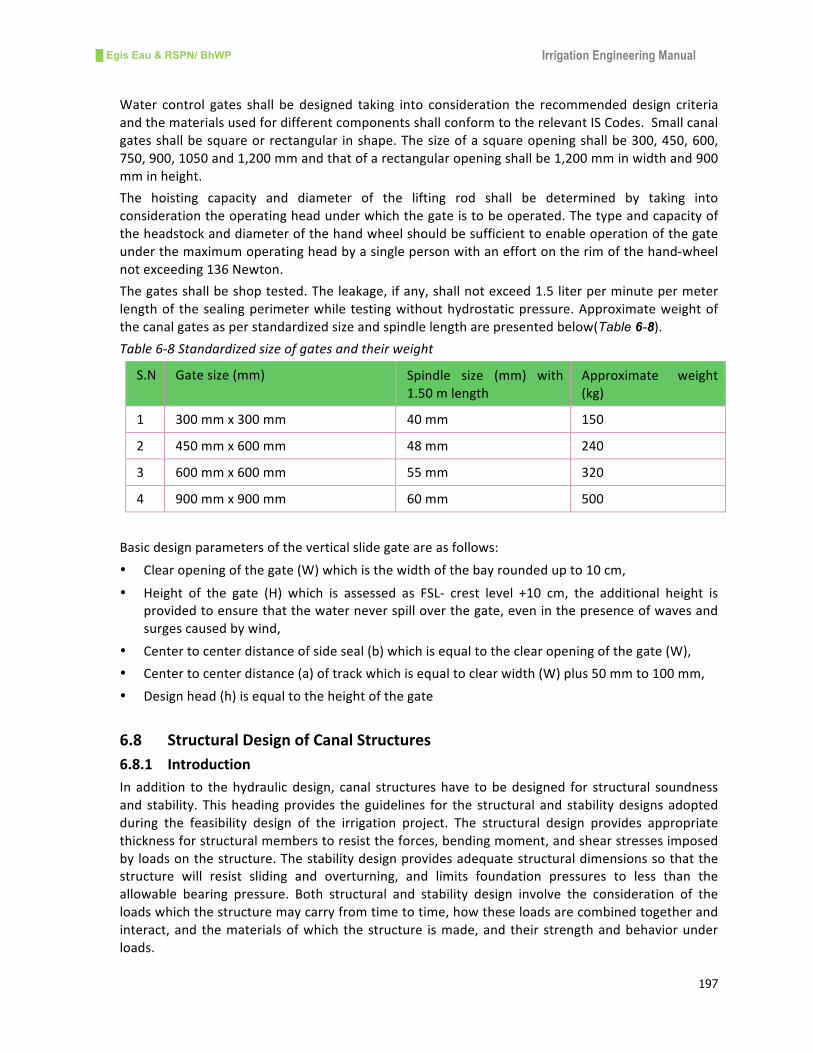
█ Egis Eau & RSPN/ BhWP Irrigation Engineering Manual
197
Water control gates shall be designed taking into consideration the recommendeddesign criteria
andthematerialsusedfordifferentcomponentsshallconformtotherelevantISCodes.Smallcanal
gatesshallbesquareorrectangular inshape.Thesizeofasquareopeningshallbe300,450,600,
750,900,1050and1,200mmandthatofarectangularopeningshallbe1,200mminwidthand900
mminheight.
The hoisting capacity and diameter of the lifting rod shall be determined by taking into
considerationtheoperatingheadunderwhichthegateistobeoperated.Thetypeandcapacityof
theheadstockanddiameterofthehandwheelshouldbesufficienttoenableoperationofthegate
underthemaximumoperatingheadbyasinglepersonwithaneffortontherimofthehand-wheel
notexceeding136Newton.
Thegatesshallbeshoptested.Theleakage,ifany,shallnotexceed1.5literperminutepermeter
lengthof thesealingperimeterwhile testingwithouthydrostaticpressure.Approximateweightof
thecanalgatesasperstandardizedsizeandspindlelengtharepresentedbelow(Table 6-8).
Table6-8Standardizedsizeofgatesandtheirweight
S.N Gatesize(mm) Spindle size (mm) with
1.50mlength
Approximate weight
(kg)
1 300mmx300mm 40mm 150
2 450mmx600mm 48mm 240
3 600mmx600mm 55mm 320
4 900mmx900mm 60mm 500
Basicdesignparametersoftheverticalslidegateareasfollows:
• Clearopeningofthegate(W)whichisthewidthofthebayroundedupto10cm,
• Height of the gate (H) which is assessed as FSL- crest level +10 cm, the additional height is
providedtoensurethatthewaterneverspilloverthegate,eveninthepresenceofwavesand
surgescausedbywind,
• Centertocenterdistanceofsideseal(b)whichisequaltotheclearopeningofthegate(W),
• Centertocenterdistance(a)oftrackwhichisequaltoclearwidth(W)plus50mmto100mm,
• Designhead(h)isequaltotheheightofthegate
6.8 StructuralDesignofCanalStructures
6.8.1 Introduction
Inaddition to thehydraulicdesign, canal structureshave tobedesigned for structural soundness
and stability. Thisheadingprovides theguidelines for the structural and stabilitydesignsadopted
during the feasibility design of the irrigation project. The structural design provides appropriate
thicknessforstructuralmemberstoresisttheforces,bendingmoment,andshearstressesimposed
byloadsonthestructure.Thestabilitydesignprovidesadequatestructuraldimensionssothatthe
structure will resist sliding and overturning, and limits foundation pressures to less than the
allowable bearing pressure. Both structural and stability design involve the consideration of the
loadswhichthestructuremaycarryfromtimetotime,howtheseloadsarecombinedtogetherand
interact,and thematerialsofwhich thestructure ismade,and their strengthandbehaviorunder
loads.

█ Egis Eau & RSPN/ BhWP Irrigation Engineering Manual
198
6.8.2 LoadingsandStructuralAnalysis
a) General
Loads are normally grouped into two categories: dead loads and live loads. Dead loads may be
describedasthosewhicharealwayspresent,whereasliveloadsaretransient.Themainloadswhich
canalstructuresmustbecapableoftakingare:
• Self-weight;
• Earthpressure;
• Waterpressureincludinguplift;
• Imposedliveloadssuchastrafficloads,
• Imposeddeadloadssuchasspanloadsetc.
• Earthquakeloading
Windloadingisignoredinthedesignasallowablelateralloadswilldominate.
b) WeightofMaterials
Theweightsofmaterialusedtoderivetheself-weightofstructuresarepresented intabular form
(Table6-9).
Table6-9Self-weightofmaterials
S.N Material Unit weight
(kN/m3)
S.N Material Unit weight
(kN/m3)
1 Steel 78.5 6 Earthdry 16.0
2 Reinforcedconcrete 24.0 7 Earthwet 20.0
3 Plainconcrete 23.0 8 Gravel 18.0
4 Stonemasonry 21.0 9 Water 9.80
5 Gabions 14.0 10 Timber 6.00
c) LateralPressure
Lateralpressuresneedtobeconsideredinthedesignofthestructurewallsagainstoverturning,and
aremainlycausedbywater,earthandtrafficloadings.Earthquakesalsowill inducelateralthrusts.
Thefollowingsectionpresentstheformulasforcalculatingtheselateralpressurestobeincurredon
thestructures.
Waterpressure
Waterpressureactingonthestructureiscalculatedas:
Pw=½Ƴh2
Where,Ƴistheunitweightofwater=9.80kN/m3,
histhedepthofwaterabovebaseinm,
Water pressure (Pw) acts at 1/3 of its height.Water pressure canbe reducedby providingweep
holesontheretainingwalls.Afilterbacking isalsonecessarytopreventwashoutofsoilparticles
withwater.
Earthpressure
Twotypesofearthpressuresactontheretainingwalls.Activeearthpressureisthepressureofthe
earthwhichiscausingthewalltomoveawayfromtheearth.Passivepressureisthepressureofthe
earthwhichisresistingmovement.TheactiveearthpressureiscalculatedbyRankinsformula:
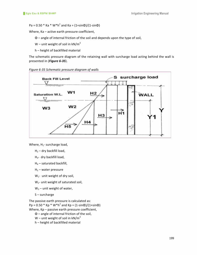
█ Egis Eau & RSPN/ BhWP Irrigation Engineering Manual
199
Pa=0.50*Ka*W*h2andKa=(1+sinΦ)/(1-sinΦ)
Where,Ka–activeearthpressurecoefficient,
Φ–angleofinternalfrictionofthesoilanddependsuponthetypeofsoil,
W–unitweightofsoilinkN/m3
h–heightofbackfilledmaterial
Theschematicpressurediagramoftheretainingwallwithsurchargeloadactingbehindthewall is
presentedin(Figure6-35).
Figure6-35Schematicpressurediagramofwalls
Where,H1-surchargeload,
H2–drybackfillload,
H3-drybackfillload,
H4–saturatedbackfill,
H5–waterpressure
W1-unitweightofdrysoil,
W2-unitweightofsaturatedsoil,
W3–unitweightofwater,
S–surcharge
Thepassiveearthpressureiscalculatedas:
Pp=0.50*Kp*W*h2andKp=(1-sinΦ)/(1+sinΦ)
Where,Kp–passiveearthpressurecoefficient,
Φ–angleofinternalfrictionofthesoil,
W–unitweightofsoilinkN/m3
h–heightofbackfilledmaterial

█ Egis Eau & RSPN/ BhWP Irrigation Engineering Manual
200
Surcharge
Traffic loads includingconstructionandoperatingequipmentandpeople/animalscauseadditional
lateralpressureonthewallsandabutments.Anassumedvalueofsurcharge isconsideredfor the
designofwallsandabutments.
Earthquake
Earthquakeloadingsarecalculatedusinganaccelerationcoefficient,whichismultipliedbythedead
loadofthestructuretoproduceadditionalhorizontalloadactingatthecentreofthegravityofthe
structure.Forsmallcanalstructuresearthquakeloadcanbeignored.
Self-Weight
Self-weight is the weight of the structure itself. In stability calculations the self weight resists
overturningandslidingforces.
UpliftPressure
Uplift isthepressureunderneaththestructurecausedbywaterpressureoneitherside.Theuplift
counteractstheself-weightinresistingslidingandoverturning.
BaseFriction
Basefrictionistheforcealongthebaseofthestructurewhichresistssliding.Itiscalculatedas:
BF=(W-U)tanΦ
Where,W-self-weight,
U–uplift,and
Φ–angleofinternalfriction
6.8.3 FactorsofSafetyforStability
Stabilityanalysisofcanalstructuresnormallyinvolves:
• Assessmentofresistanceagainstoverturning;
• Assessmentofresistancetosliding;and
• Assessmentofpositionofthebasereaction
Thefactorsofsafetyadoptedforthedesignofcanalstructuresagainstoverturningare:
• 2.00fornormalloadingcases,
• 1.50forextremeloadingcases
Thefactorsofsafetyadoptedforthedesignofcanalstructurestoslidingare:
• 1.50fornormalloadingcases,
• 1.20forextremeloadingcases
Thereactionmustbewithinthemiddlethirdofthestructurei.e.notensionbetweenbaseandsoil
isallowed.
6.8.4 BearingPressures
Thefoundationscanfailintwoways:byshearfailureorbysettlement.Thefoundationsshouldbe
safeagainstshearandthelimingfactorwillbethesettlement.Themaximumallowablesettlement
offoundationsforcanalstructuresshouldbetakenas25mm.Theallowablebearingpressureofthe
soil is calculated from theDirect Cone Penetrometer (DCP) test carried out along themain canal
alignment. The allowable bearing pressure of various soils is also estimated from standard civil
engineeringbooks(Table6-10).

█ Egis Eau & RSPN/ BhWP Irrigation Engineering Manual
201
Table6-10Allowablebearingpressureofthesoil
S.N Soiltype Allowable bearing pressure
(kN/m2)
1 Softclaysandsilts <80
2 Firmclaysandfirmsandyclays 100
3 Stiffclaysandstiffsandyclays 200
4 Verystiffboulderclays 350
5 Compactwellgradedsandsandgravel/sandmixtures 200
6 Looseuniformsand 150
6.8.5 SeepageandUpliftDesign
All hydraulic structures built on pervious foundations exhibit seepage flow underneath the
structure. Thewater seepingbelow thebodyof thehydraulic structureendangers the stabilityof
thestructureandmaycauseitsfailureintwoways:
• Bypiping,or
• Bydirectuplift
Failurebypipingoccurswhenseepagewaterretainssufficientresidualforceatdownstreamendsof
thestructure.Theseepingwatermayliftsoilparticlesandmayleadtotheprogressiveremovalof
the soil underneath the foundation. The structuremayultimately subside intoahollow, resulting
intoitsfailure.
Failurebyupliftoccurswhenseepingwaterbelowthestructureexertsupliftpressureonthefloorof
thestructure. Ifthispressureisnotcounterbalancedbytheweightofthefloor,thestructurewill
failbyaruptureofpartofthefloor.Theseepagepathofthesub-surfaceflowisillustratedinsketch
(Figure6-36).
Figure6-36Sketchofseepagepathunderneaththestructure
Bligh’screeptheory,Lane’sweightedcreeptheoryandKhosla’stheoryarethemostcommonlyused
methodstoassessseepageandupliftforhydraulicstructuresbuiltonperviouslayers.Smallcanal
structuresaredesignedbasedonLane’sweightedcreeptheoryorBligh’screeptheorywhile large
structures are designed based on Khosla’s theory of independent variables. Head regulators and

█ Egis Eau & RSPN/ BhWP Irrigation Engineering Manual
202
small canal structuresaredesignedusing Lane’smethodwhile cross regulators aredesignedwith
Khosla’smethod.ThelengthoftheweightedcreepasperLane’smethodisasfollows:
LW=H/3+VwhichmustnotbelessthanCW*HL
Where,LWistheweightedcreeplengthinm,
Histhesumofhorizontalseepagepercolationpathlinesinm,
Visthesumofverticalpercolationpathlinesinm,
HListhemaximumheadofwateracrossthestructureinm,and
CWistheweightedcreeprationwhichisbasedonthetypeofsoilasgiven(Table6-11).
Table6-11Lanesweightedcreepratio
S.N Typeofsoil Weighted creep
ratio(CW)
1 Veryfinesandandsilt 8.50
2 Finesandandalluvialsoil 7.00
3 Coarsesand 5.00
4 Finegravel 4.00
5 Coarsegravel 3.00
6 Softclay 3.00
7 Hardclay 1.80
8 Veryhardclayandimperviouslayer 1.60
6.8.6 ConcreteDesign
General
The concrete design is carried out with permissible limit state method using Indian Standard
IS456:2000 Plain and Reinforced Cement Concrete-Code of Practice. Irrigation structures are
designed to be built with mass and reinforced concrete complying IS456:200. The density of
reinforcedconcreteistakenas24kN/m3.
ConcreteGrades
Gradingof concrete is basedon the characteristic compressive strengthof the concrete,which is
definedasthe28daystrengthbelowwhichnotmorethan5percentofthetestedspecimensfail.
The specified characteristic compressive strength is that of a 150mm cube at days, expressed in
N/mm2. The following concrete grades are used in the design of the irrigation structures (Table
6-12).
Table6-12ConcreteGradesandUses
Concrete
Grade
Typical Mix
(cement: sand:
aggregate)
Specified
characteristic
compressive strength
at28days(N/mm2)
Useofconcretegrades
M10 1:3:6 10 Blinding concrete/lean
concrete

█ Egis Eau & RSPN/ BhWP Irrigation Engineering Manual
203
Concrete
Grade
Typical Mix
(cement: sand:
aggregate)
Specified
characteristic
compressive strength
at28days(N/mm2)
Useofconcretegrades
M15 1:2:4 15 Mass concrete, cast in situ
concreteslabs
M20 1:1.5:3 20 Reinforced
concrete/structuralconcrete
M25 1:1:2 25 Water retaining structures,
reinforcementconcrete
Source:PWVDP,IrrigationManual,1992
ReinforcementSteel
Thereinforcementshouldcomplywith IS1786, ISO4066:2000,AASTHO/2007,allofwhichspecify
thetestsforcompliancetoobtainthecharacteristicstrength(Table6-13).
Table6-13ReinforcementBars
Grade Nominalsizeofbars
(mm)
Minimumyield
stress(Mpa)
Type
500 8mmto32mm 500 TMTbars(Thermo
mechanicallytreated)
The cover of concrete to reinforcement depends on the dimensions of structural elements,
maximumsizeofaggregateandconditionsofcontacttowaterandsoil.Theminimumcovershallbe
notlessthanthatthespecifiedvaluesorgreaterthannominalsizeofaggregate.

█ Egis Eau & RSPN/ BhWP Irrigation Engineering Manual
204
CHAPTER-7
7. MicroIrrigation
7.1 Introduction
Micro irrigation refers to the alternativemethods of irrigationwater acquisition, conveyance and
application as an efficient way to providewater to plants. The concept and technology ofmicro
irrigationwas firstdeveloped in Israel in the1960s. Sprinkler irrigationanddrip irrigationare the
mainmicro irrigationmethodsofwaterapplicationbeingadoptedworldwide. Thesetechnologies
are especially suitable for smallholder farmers of arid and semiarid regions of Asia and Africa.
Despite the abundance of water in Bhutan, its availability in time and space limits irrigation for
smallholderfarmers,whomostlydependonerraticrainfallpatterns.Numeroussmallstreamsand
springsscatteredaroundthehillsofBhutancanbeeffectivelytappedformicroirrigation.Likewise,
inthesmallplotsof landwith limitedwatersources,micro irrigationcanbe introducedefficiently
fortheproductionofmorevaluablecrops.Inacontextwheresmallwatersourcesaredryingupdue
to climate change, water harvesting technologies and efficient water application methods are
climateresilienttechnologiesforirrigatedagriculture.
Hence,micro irrigation is related to thealternativemethodsofbothwater applicationandwater
acquisitionforirrigation.Thischapterdealswiththeconceptanddesignofsprinklerirrigation,drip
irrigationandwaterharvestingmethodsofmicroirrigationtechnologiesfeasibleforBhutan.
7.2 SprinklerIrrigationSystem
7.2.1 General
A sprinkler systemapplieswater for irrigation in the formof a spraywhich somewhat resembles
rainfall.Thesprayisdevelopedbytheflowofwaterunderpressurethroughsmallorificesornozzles
referred to as sprinklers. The water pressure in the sprinkler pipes can be developed either by
pumpingfromlowerelevationsorbyflowingfromhigherelevationsbygravity.Inaddition,sprinkler
irrigationisparticularlysuitableforwaterscarceareas,hillslopesandhigherodiblesoils.Toprevent
water pooling and surface run-off, sprinklers are designed to applywater at a rate that does not
exceedtheinfiltrationcapacityofthesoil.
7.2.2 AdvantagesofSprinklerIrrigation
Sprinkle irrigation has several advantages over conventional surface irrigation methods. The
versatility of use in different land, soil, and crop conditions are the key features of the sprinkle
irrigationmethod.Theadvantagesofasprinkleirrigationsystemaredescribedhereunder:
i. Controloverwater
Sprinklerirrigationoffersahighdegreeofcontrolledwaterapplication.Theamountandfrequency
ofwatercanbecontrolledveryefficiently.Inaddition,overirrigation,pounding,andrunoffcanbe
eliminated through the control ofwater application. Thiswill help tomaintain optimum growing
conditionsofthecropsandoptimumwaterutilization.
ii. Savingofwater
In sprinkler irrigation, water is supplied through the pipes and relatively high degree of water
distributionuniformitycanbeattained.Thuswithagivenquantityofwater, thesprinklermethod
canirrigateamuchlargerareathansurfaceirrigation.Inotherwords,irrigationrequireslesswater
█ Egis Eau & RSPN/ BhWP Irrigation Engineering Manual
205
perunitarea. Inawell-managedsystem,theapplicationefficiencyofasprinklersystemcanbeas
high as 75%, against 50% in flood irrigation. Furthermore, small water sources can be utilized
effectively.
iii. SavingofLabor
Sprinkler irrigation requires less labor for theoperationandmanagementof the irrigation system
becauseitdoesnotrequirethesameattentionassurfaceirrigation.Soildoesnottendtoclodunder
sprinkler irrigationandaswater isuniformlydistributedover theentire landarea, land leveling is
alsonotrequired.Thiswillsavethecostoflandpreparationandtopsoilwithhigherfertilitywillnot
bedisturbed.
iv. Protectionofthesoilandcrops
Damageofsoilsandcropsduetofrostandwindcanbeminimizedwithsprinkler irrigation.This is
moreimportantforcropsatgerminationandearlystages.Thecontrolledapplicationpreventssoil
erosionandalsohelpskeepgoodsoilstructure.
v. Adaptationtomarginalsoils
Asprinkler irrigationsystemcanbedesigned tooperateefficientlyonalmostall topography.This
methodmaybeaneffectivetechniquetoirrigateintheslopingterrain,irregularplotsandmarginal
soilconditions.
vi. Efficientuseoftheland
Sinceconveyancechannelsandbundsarenotrequiredinsprinklerirrigation,almosttheentirearea
canbeusedforcropproduction.Bunds,levees,andthewatercoursesoftenoccupyanappreciable
amountoflandareawhichcannotbeputundercultivation.
7.2.3 ConstraintsofSprinklerIrrigation
Despitetheseveraladvantagesofsprinkler irrigation, therearesomeconstraints in itsapplication
whicharepresentedbelow.
i. Highinvestmentcost
Theinitialinvestmentcostofsprinklerirrigationisrelativelyhigh.Inaddition,runningcostsarealso
highbecausesprinklersrequireenergytooperate.
ii. EffectofthePressure
Water distribution of the sprinkler is greatly affected by the pressure ofwater. If the pressure is
aboveor below theoptimum,waterwill not be uniformly distributed.At lowpressure,water jet
does not break up andmost of thewater tends to fall at some distance from the sprinkler. The
largerdropswillalsodamagethesoilstructureandthecrop.Ontheotherhand,ifthepressureis
toohigh,afinespraywilldevelopintheformofmistthatfallsclosetothesprinkler.
iii. Effectofthewind
Waterdistributionremainspoorifthesprinklersareoperatedinwindyconditions.Thefinesprays
fromsprinklerscanbeeasilyblownawaybythewind,whichwilldistortthewettingpatterns.Thisin
turnwillupsetirrigationuniformity.
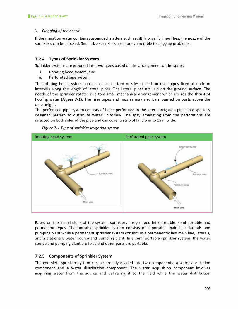
█ Egis Eau & RSPN/ BhWP Irrigation Engineering Manual
206
iv. Cloggingofthenozzle
Iftheirrigationwatercontainssuspendedmatterssuchassilt,inorganicimpurities,thenozzleofthe
sprinklerscanbeblocked.Smallsizesprinklersaremorevulnerabletocloggingproblems.
7.2.4 TypesofSprinklerSystem
Sprinklersystemsaregroupedintotwotypesbasedonthearrangementofthespray:
i. Rotatingheadsystem,and
ii. Perforatedpipesystem
The rotating head system consists of small sized nozzles placed on riser pipes fixed at uniform
intervals along the length of lateral pipes. The lateral pipes are laid on the ground surface. The
nozzleof thesprinkler rotatesduetoasmallmechanicalarrangementwhichutilizes the thrustof
flowingwater (Figure 7-1). The riser pipes andnozzlesmay also bemountedonposts above the
cropheight.
Theperforatedpipesystemconsistsofholesperforatedinthelateral irrigationpipesinaspecially
designed pattern to distribute water uniformly. The spay emanating from the perforations are
directedonbothsidesofthepipeandcancoverastripofland6mto15mwide.
Figure7-1Typeofsprinklerirrigationsystem
Rotatingheadsystem Perforatedpipesystem
Based on the installations of the system, sprinklers are grouped into portable, semi-portable and
permanent types. The portable sprinkler system consists of a portable main line, laterals and
pumpingplantwhileapermanentsprinklersystemconsistsofapermanentlylaidmainline,laterals,
and a stationarywater source andpumpingplant. In a semiportable sprinkler system, thewater
sourceandpumpingplantarefixedandotherpartsareportable.
7.2.5 ComponentsofSprinklerSystem
The complete sprinkler system can be broadly divided into two components: awater acquisition
component and a water distribution component. The water acquisition component involves
acquiring water from the source and delivering it to the field while the water distribution
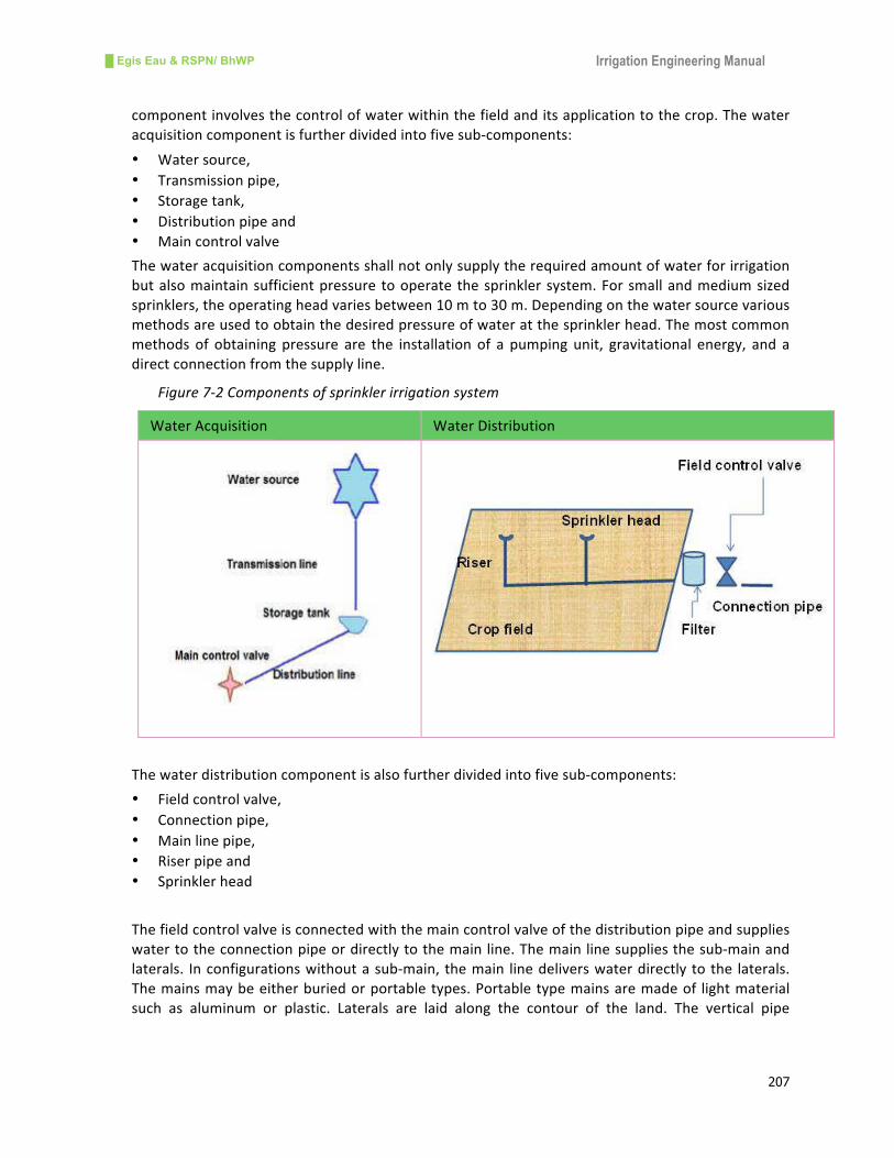
█ Egis Eau & RSPN/ BhWP Irrigation Engineering Manual
207
componentinvolvesthecontrolofwaterwithinthefieldanditsapplicationtothecrop.Thewater
acquisitioncomponentisfurtherdividedintofivesub-components:
• Watersource,
• Transmissionpipe,
• Storagetank,
• Distributionpipeand
• Maincontrolvalve
Thewateracquisitioncomponentsshallnotonlysupplytherequiredamountofwaterforirrigation
butalsomaintainsufficientpressuretooperate thesprinklersystem.Forsmallandmediumsized
sprinklers,theoperatingheadvariesbetween10mto30m.Dependingonthewatersourcevarious
methodsareusedtoobtainthedesiredpressureofwateratthesprinklerhead.Themostcommon
methods of obtaining pressure are the installation of a pumping unit, gravitational energy, and a
directconnectionfromthesupplyline.
Figure7-2Componentsofsprinklerirrigationsystem
WaterAcquisition WaterDistribution
Thewaterdistributioncomponentisalsofurtherdividedintofivesub-components:
• Fieldcontrolvalve,
• Connectionpipe,
• Mainlinepipe,
• Riserpipeand
• Sprinklerhead
Thefieldcontrolvalveisconnectedwiththemaincontrolvalveofthedistributionpipeandsupplies
watertotheconnectionpipeordirectlytothemainline.Themainlinesuppliesthesub-mainand
laterals. Inconfigurationswithoutasub-main, themain linedeliverswaterdirectly tothe laterals.
Themainsmaybeeitherburiedorportabletypes.Portabletypemainsaremadeof lightmaterial
such as aluminum or plastic. Laterals are laid along the contour of the land. The vertical pipe

█ Egis Eau & RSPN/ BhWP Irrigation Engineering Manual
208
connectinglateralswiththesprinklerheadiscalledariserpipe.Theschematicdiagramofsprinkler
systemcomponentsispresentedinFigure7-2.
7.2.6 DesignConceptofSprinklerSystem
Thedesignofasprinklersysteminvolvestheassessmentofthewatersource,shapeandsizeofthe
fieldtobeirrigated,cropstobeplanted,topographyofthearea,andirrigationrequirements.The
watersourceshouldbenearesttotheirrigationcommandareainordertoavoidthecostofwater
conveyance.
Asprinklersystemmustbedesignedtoapplywateruniformlywithoutsurfacerunofforsoilerosion.
Theapplicationratemustmatchtheinfiltrationrateofthesoil.Thecapacityofthesprinklersystem
depends on the peak water requirement during the crop growing season, effective crop rooting
depth,typeofsoil,andavailablewaterorpumpingrate.
The sprinkler irrigation system shall be selectedwith the thorough evaluation of the specific site
conditionsandthecomputationoftheavailableflow.Oncethedesignofthesystemiscompleted,a
detailedlistofalltheequipmentnecessaryfortheinstallationofthesystemmustbepreparedwith
fulldescriptions,standards,andspecificationsofeveryitem.Typicalsprinklersarepresentedbelow
(Figure 7-3)
Figure7-3Typicalsprinklerirrigations
7.2.7 DesignProcedures
i. Layoutplanoftheplottobeirrigated
- Dividetheareasintoblocks,
- Decidethetypeofsprinklersystem:permanentorportable,
- Decidewaterrequirementbasedoncropstobeplanted,
- Decideoperatingpressure
ii. Calculatenumberofsprinklersandselectthesizeofthenozzle
- Basedon the soil infiltration rate (Table7-1), slope,andavailablepressure selectappropriate
sprinkler and recommended spacing between sprinklers. This information is available on the
productcatalogueofthemanufacturer,
- Calculatethewaterapplicationrate,

█ Egis Eau & RSPN/ BhWP Irrigation Engineering Manual
209
Applicationrate=flowrateofonesprinkler(lpm)*60/(areabetweensprinklers(sqm))
- Calculatenumberofsprinklersandtheirspacing
Table7-1Infiltrationrateofdifferentsoils
SoiltypeClay Cayloam Siltloam Sandyloam Sand
Water intake rate
(mm/h)
1to5 6to8 7to10 8to12 10to25
iii. Designoflaterals
- Determinethelength,directionandnumberoflaterals,
- Determineflowrateoflateral=numberofemitterperlateralxemitterflowrate
- Numberoflateralsoperatingsimultaneously=systemflow/flowrateoflateral
- Numberofshiftstocompleteoneirrigation=totalnumberoflaterallines/numberoflaterals
operatingsimultaneously
- Durationofapplication=irrigationrequirementinmm/applicationrateinmm
- Orirrigationrequirementinm3perhour/systemflowinm3perhour
iv. Determinationofthesizesofthepipeline
- Designoflateralpipeinvolves:
- Assumediameteroflateralforvaryinglateralflow,
- Computeheadlossinlateralandcheckavailableatitstwocorners,
- Adoptassumeddiameterifheadlossisacceptable
- Designofsub-mainline,
- Similartodesignoflateralsanddischargedecreasesfromheadtotail,
- Computeheadlossandcheckitwithavailablehead,
- Designofmainline,
- Dischargeinmainlineisconstantthroughthelength,
- Computetheheadlossandcheckitwithavailablehead,
HeadlossduetofrictioninlateralsoftheplasticpipeisgivenbyHazenWilliams’sequation:
FLD
QHf ××=
872.4
852.1
27.15
Where,Hfisheadlossduetofrictioninm,
Qistheincomingdischargeinthelateral(lps)
Distheinternaldiameterofthelateral(plasticpipe)incm
Listhetotallengthofthelateralinm
F is the reduction factoror correction factor forhead lossdue to friction inpipewith
multipleoutlets.ThevalueofFdependsonthenumberofoutletsinonelateral(Table
7-2).
Table7-2F-factorvalueforheadlossinpipes
Numberofoutlets F-value Numberofoutlets F-value
1 1.00 12 0.376
2 0.62 15 0.367
3 0.52 20 0.36

█ Egis Eau & RSPN/ BhWP Irrigation Engineering Manual
210
Numberofoutlets F-value Numberofoutlets F-value
4 0.47 24 0.355
5 0.44 28 0.351
6 0.42 30 0.35
7 0.41 40 0.345
8 0.40 50 0.343
9 0.39 100 0.338
10 0.385 >100 0.333
Source:FAO,2000
v. Designofstoragetank
- Designofstoragetankisnecessarytogetheadforsprinklers,
- Forhillyregionorterracedlandatleast25mofheadisavailableforsprinklers,
- Thecapacityofstoragetankshallbefixedforonedayirrigation,
- Thecapacityisbasedonthenumberoflateralsanditsdischargingcapacity
7.2.8 DesignExampleofSprinklerSystem
Data
OnevillageinTsirangnearDamphutownhas22households.Eachhouseholdhasabout0.25acres
ofuplandnearthehomesteadandaspringwatersourceisalsolocatedatadistanceofabout1km
fromthevillage.Theverticalheightdifferencebetweenthesourceandthevillageisapproximately
115m.Themeasureddischargeof thewaterat the spring source inMay is2.2 litersper second.
Eachhouseholdinthecommunityiswillingtogrowvegetables.
Layoutofthesystem
The layout of the sprinkler system consists of intake at the source andmain pipe line up to the
storage reservoir. From the reservoir, water will be distributed to the six outlets or taps. It is
assumedthat4to5householdswilluseoneoutletandirrigatetheirfields.Thelayoutofthesystem
ispresentedinFigure7-4.
Wateravailabilityassessment
Itislearntthatthesourceofwaterforthesprinklerirrigationsystemisperennialandthemeasured
flow inMay is 2.2 lps. Considering the reliability of themeasured flow the available flow at the
sourceisassessedas1.80lps.
Theavailableflowperday=1.80x3600x24=155,520liter==155.50m3perday
Calculationofcropwaterrequirement
The crop water requirement is calculated based on potential evapo-transpiration (ETo) using
CropWat-8.ForDamphutownEToispresentedinTable7-3.
Table7-3Referencecropevapo-transpirationandcropcoefficients
Month ETo(mm/day) Crop Maximumcrop
coefficientvalues
January 1.81 Onion 1.15
February 2.26 Cauliflower 1.05
March 2.99 Cabbage 1.05
April 3.45 Cucumber 1.15
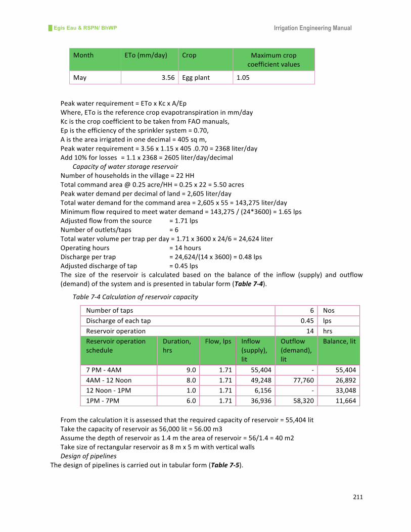
█ Egis Eau & RSPN/ BhWP Irrigation Engineering Manual
211
Month ETo(mm/day) Crop Maximumcrop
coefficientvalues
May 3.56 Eggplant 1.05
Peakwaterrequirement=EToxKcxA/Ep
Where,EToisthereferencecropevapotranspirationinmm/day
KcisthecropcoefficienttobetakenfromFAOmanuals,
Epistheefficiencyofthesprinklersystem=0.70,
Aistheareairrigatedinonedecimal=405sqm,
Peakwaterrequirement=3.56x1.15x405.0.70=2368liter/day
Add10%forlosses =1.1x2368=2605liter/day/decimal
Capacityofwaterstoragereservoir
Numberofhouseholdsinthevillage=22HH
[email protected]/HH=0.25x22=5.50acres
Peakwaterdemandperdecimalofland=2,605liter/day
Totalwaterdemandforthecommandarea=2,605x55=143,275liter/day
Minimumflowrequiredtomeetwaterdemand=143,275/(24*3600)=1.65lps
Adjustedflowfromthesource =1.71lps
Numberofoutlets/taps =6
Totalwatervolumepertrapperday=1.71x3600x24/6=24,624liter
Operatinghours =14hours
Dischargepertrap =24,624/(14x3600)=0.48lps
Adjusteddischargeoftap =0.45lps
The size of the reservoir is calculated based on the balance of the inflow (supply) and outflow
(demand)ofthesystemandispresentedintabularform(Table7-4).
Table7-4Calculationofreservoircapacity
Numberoftaps 6 Nos
Dischargeofeachtap 0.45 lps
Reservoiroperation 14 hrs
Reservoiroperation
schedule
Duration,
hrs
Flow,lps Inflow
(supply),
lit
Outflow
(demand),
lit
Balance,lit
7PM-4AM 9.0 1.71 55,404 - 55,404
4AM-12Noon 8.0 1.71 49,248 77,760 26,892
12Noon-1PM 1.0 1.71 6,156 - 33,048
1PM-7PM 6.0 1.71 36,936 58,320 11,664
Fromthecalculationitisassessedthattherequiredcapacityofreservoir=55,404lit
Takethecapacityofreservoiras56,000lit=56.00m3
Assumethedepthofreservoiras1.4mtheareaofreservoir=56/1.4=40m2
Takesizeofrectangularreservoiras8mx5mwithverticalwalls
Designofpipelines
Thedesignofpipelinesiscarriedoutintabularform(Table7-5).
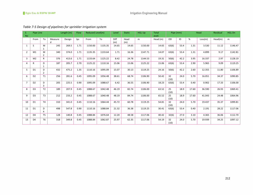
█ Egis Eau & RSPN/ BhWP Irrigation Engineering Manual
212
Table7-5Designofpipelinesforsprinklerirrigationsystem
S
No
PipeLine Length(m) Flow ReducedLevel(m) Level Static HGLUp Total
avail.
Pipe(mm) Head Residual HGLDn
From To Measure
d
Design lps From To Diff
(m)
Head
(m)
m Head(m) OD ID % Loss(m) Head(m) m
1 S M
1
245 269.5 1.71 1150.00 1135.35 14.65 14.65 1150.00 14.65 63(6) 53.4 1.31 3.530 11.12 1146.47
2 M1 M
2
340 374.0 1.71 1135.35 1133.64 1.71 16.36 1147.71 14.07 63(6) 53.4 1.31 4.899 9.17 1142.81
3 M2 R 376 413.6 1.71 1133.64 1125.22 8.42 24.78 1144.53 19.31 50(6) 42.2 3.95 16.337 2.97 1128.19
4 R D
1
187 205.7 2.70 1125.22 1110.16 15.06 15.06 1125.22 15.06 63(6) 53.4 2.90 5.965 9.09 1119.25
5 D1 D
2
432 475.2 1.35 1110.16 1095.09 15.07 30.13 1119.25 24.16 50(6) 42.2 2.60 12.355 11.80 1106.89
6 D2 T1 256 281.6 0.45 1095.09 1056.48 38.61 68.74 1106.90 50.42 32
(10)
24.0 5.70 16.051 34.37 1090.85
7 D2 D
3
205 225.5 0.90 1095.09 1088.67 6.42 36.55 1106.90 18.23 63(6) 53.4 0.40 0.902 17.33 1106.00
8 D3 T2 189 207.9 0.45 1088.67 1042.48 46.19 82.74 1106.00 63.52 25
(10)
18.9 17.60 36.590 26.93 1069.41
9 D3 T3 212 233.2 0.45 1088.67 1040.48 48.19 84.74 1106.00 65.52 25
(10)
18.9 17.60 41.043 24.48 1064.96
10 D1 T4 310 341.0 0.45 1110.16 1064.44 45.72 60.78 1119.25 54.81 32
(10)
24.0 5.70 19.437 35.37 1099.81
11 D1 D
4
498 547.8 0.90 1110.16 1088.84 21.32 36.38 1119.25 30.41 63(6) 53.4 0.40 2.191 28.22 1117.06
12 D4 T5 128 140.8 0.45 1088.84 1076.64 12.20 48.58 1117.06 40.42 32(6) 27.0 3.10 4.365 36.06 1112.70
13 D4 T6 318 349.8 0.45 1088.84 1062.87 25.97 62.35 1117.06 54.19 32
(10)
24.0 5.70 19.939 34.25 1097.12

█ Egis Eau & RSPN/ BhWP Irrigation Engineering Manual
213
Figure7-4LayoutPlanofSprinklerIrrigationSystem

█ Egis Eau & RSPN/ BhWP Irrigation Engineering Manual
214
7.3 DripIrrigation
7.3.1 General
Drip irrigation isawaterapplicationmethodwhich irrigatesonlypartof thesoilat theplant root
zone.Dripirrigationisalsoreferredtoastrickleirrigationandinvolvesdrippingwaterintothesoilat
averylowrate(2-20literperhour).Thismethodconsistsofapipednetworkoflateralslaiddown
onthegroundorburiedatashallowdepthwithlowflowoutletscalledemittersordrippers.These
emittersaredesignedtoemitatrickleratherthanajetofwaterandareplacedsoastoproducea
wetstripalongtheplantroworawettedbulbofsoilateveryplant(Figure7-5).
Thistypeofirrigationisusuallypracticedinwaterscarceareasforspacingcropslikefruits,flowers
and vegetables. It is considered to be one of themost efficientmethods ofwater application tomeetcrop waterrequirements,andneedssixtoeighttimes lesswatercomparedtoconventional
irrigationsystems. InternationalDevelopmentEnterprise (IDE),an internationalnon-governmental
organization (INGO) has developed a simple drip irrigation technology being used in developing
countriesincludingNepalandBhutan.Duetoitssimplifiedtechnologyandfarmers’engagementin
high-valueagriculture,dripirrigationisnowshowinggreatpromiseforraisingthelandproductivity,
waterefficiencyandincomesofpoorsmallholders(Polak,2001).Moreover,theapplicationofdrip
irrigation ispopular inseveraldevelopingaswellasdevelopedcountriesduetohighercropyields
andhigherwateruseefficiency.
Figure7-5Examplesofdripirrigationmethod
Spacingofcropsindripirrigation Largescaledripirrigation
7.3.2 AdvantagesofDripIrrigation
Adripirrigationsystemoffersspecialagronomical,agro-technicalandeconomicadvantagesforthe
efficient use of water and labor. Furthermore, it provides an effective means for utilizing small
streamsofwater.Theadvantagesofdripirrigationsystemaredescribedhereunder:
i. Controloverwater
Dripirrigationoffersahighdegreeofcontrolledwaterapplication.Theamountandthefrequency
of water application can be controlled very finely. This will help to maintain optimum growing
conditionsofthecropswithoptimumutilizationofwater.

█ Egis Eau & RSPN/ BhWP Irrigation Engineering Manual
215
ii. SavingofWater
Due to thecontrolledand localizedapplicationofwater, losses fromdirectevaporationanddeep
percolationaresignificantlyminimized.Waterapplicationefficiencycanreachupto90%,compared
to70%forsprinklerand40%forsurfaceandfurrowirrigationmethods,whichinturnsaveswater
significantly.
iii. SavingofEnergyandLabor
Drip irrigationrequires less labor, lessenergyand lesspreparatorywork thanothermethodsas it
requiresrelativelylowheadtooperate,doesnotrequirelandleveling,andtherearelessweeds.In
addition,dripirrigationprovideseasieraccesstocropfieldsandthepossibilityoffertilization.
iv. Greaterandhigherqualityyield
Duetotheoptimumapplicationofwatertoeachplant,favorableagronomicconditionsarecreated
inthesoil,waterandair interfaceunderdrip irrigation,enhancingplantgrowthandyields.Asthe
crop foliage under a drip system remains dry, the incubation of the many plant pathogens is
retarded.Thesespecific featuresofdrip irrigationcontribute to less infestationresulting inhigher
andbetterqualityyield.
v. Possibilityofapplicationofnutriments,pesticides
Withdripirrigation,itispossibletoapplysolublefertilizersandchemicalsalongwiththeirrigation
water in a precise manner. This type of efficient application of fertilizer and pesticides is the
inherentadvantageofdripirrigation.
vi. Adaptationtopoorsoils1
Drip irrigation systems can be designed to operate efficiently on almost all topography including
sloping terrain, irregular plots and poor soil conditions. This is the most environment friendly
methodofirrigationthatdoesnotcauseanyerosionandlandslide.
7.3.3 LimitationsofDripIrrigationSystem
Despitethenumerousadvantagesofdripirrigation,thereareafewlimitationswhicharedescribed
hereunder.
i. Cloggingofdrippers/emitters
Clogging isoneof themajorproblemsassociatedwithdrip irrigation.Because theemitteroutlets
areverysmall,theycaneasilybecomecloggedbyparticlesofmineralororganicmattermixedwith
water.Cloggingreducesemissionratesandtheuniformityofwaterdistribution,whichcanleadto
crop loss or failure. A good filtration is the most important prerequisite for minimizing clogging
problems.
ii. Saltaccumulationinsoils
Whenbrackishwaterisusedindripirrigation,saltstendtoconcentrateatthesoilsurfaceandthe
entire wetting front. This can become a potential hazard for both the standing crop and the
subsequentcrop.Thisisbecauseofthelightrainsthatcanmovetheaccumulatedsaltsintotheroot
zone.Henceduringlightrains,supplementaryirrigationmaybenecessarytoleachexcesssalts.
iii. Distributionun-uniformityinthesteepland
Ifpoorlydesignedandimproperlymaintained,thewaterdistributionuniformityofadripsystemcan
be low in the long, sloping, or undulating fields. Furthermore, the lines will drain through lower
emittersafterthewaterisshutoffandhencesomeplantsreceivetoomuchwaterandotherstoo
little.
iv. Systemcostandcomplexityofoperation
The initial investmentcostofdrip irrigation ishighcomparedtoconventionalsurface irrigation. In
addition, drip irrigation requires trained personnel to operate and manage the system. The
1 Poor soils refer here as high porosity soils

█ Egis Eau & RSPN/ BhWP Irrigation Engineering Manual
216
constraint of investment and complexity, however, does not apply in the caseof simple low cost
dripirrigationsystems.
7.3.4 ComponentsofDripSystem
Likesprinklerirrigation,adripirrigationsystemcanalsobebroadlydividedintotwocomponents:a
water acquisition component and a water distribution component. The water acquisition
componentinvolvesacquiringwaterfromthesourceanddeliveringittothefield,whilethewater
distributioncomponentinvolvesthecontrolofwaterwithinthefieldanditsapplicationtothecrop.
Thewateracquisitioncomponentisfurtherdividedintofivesub-components:
o Watersource,
o Transmissionpipe,
o Storagetank,
o Distributionpipeand
o Maincontrolvalve
The sub-components of the water acquisition part of drip irrigation are similar to that of the
sprinkler irrigation system presented earlier. The water distribution component is also further
dividedintofivesub-components:
o Fieldcontrolvalve,
o Connectionpipe,
o Mainlinepipe,
o Lateralsand
o Emittersordrippers
Figure7-6Schematicdiagramofwaterdistributioncomponentofdripirrigationsystem
The water distribution sub-components are also similar to that of the sprinkler irrigation system
with theexceptionof the lateral pipes andemitters. Laterals are laid along the crop rowson the
groundandholdemittersordrippersatadefinitespacing.Thediameterofpipesusedforlateralsis
usually9,12and15mm.Emittersaresmalldispensingdevicesandareaffixedtothelaterals.The

█ Egis Eau & RSPN/ BhWP Irrigation Engineering Manual
217
mainfunctionoftheemitteristodischargeaconsistentamountofwaterneartheplantintheform
ofdrops. Theemitterburnsoffpressureenergy to theatmosphericpressureor to createa great
head loss. Sometimesmore thanoneemitter isprovided foronecrop,especially formature fruit
trees.Forvegetableswithsmallspacing,emittersmaybecloselyspacedtogetacontinuouswetting
pattern.Atpresentvarioustypesofdrippersarecommerciallyavailableonthemarket.Basedonthe
mechanismofdissipatingpressure,thefollowingfourtypesofemittersareusedinthedripsystem.
• Longpath:capillarysizedtubeorchannel
• Orificeemitters:nozzlewithbaffles
• Vortexemitters:employvortexeffect
• Compensatingemitters.
Inlongpathemitters,headlossesarecausedbylongitudinalfrictionofwaterflowalongthenarrow
tube thus covering a relatively long path before exit. The Orifice emitters on the other hand
dissipateenergyduetotheflowofwaterthroughaconstrictedcrosssection.TheVortextypesof
emitters compel water to whirl in a circular chamber where centrifugal opposition develops
sufficientheadlossesdespitethelargecrosssection.Compensatingdrippersfunctioninsuchaway
thatthesizeoftheorificeislargeatlowpressureandbecomessmallathighpressure.Inthisway,
theyalwaysmaintainaconstantflowoverawiderangeofpressurevariations.
7.3.5 DesignExampleofDripSystem
Data
Plotsize=12mx10m=0.012acres
Soiltype=Siltyloam
Groundslope=mildslope
Elevationofthetankabovethefarmplot=10m
Proposedcrop=vegetablesuchonion,tomato,cabbage,eggplant,caulifloweretc.,
Proposedirrigationmethod=dripirrigation
i. Layoutoftheplot
Farmplotarea=12x10m=120sqm=0.012acre
Fixthelateralalongthewidthoftheplotandlengthoflateral=10m
Spacingbetweenlaterals=1m
Providesixlateralsononesidewithaccesspathatthecenter,
Totalnumberoflaterals=2x6=12
Thespacingofemittersshallbe30cmcentretocentreandhencefor10mlateraltherewillbe30
emitters,
Assumingthesoleofthegroundislessthan3%,thedirectionofthelateralsshallbealongtheslope,
andotherwisethedirectionofthelateralsshallbealongthecontour.
ii. Calculationofcropwaterrequirement
Crop water requirement for drip irrigation is assessed for peak water requirement of daily
applicationfor8to12hours.Foraperiodoflesswaterdemand,waterapplicationhoursneedtobe
reduced.Table7-6presentsreferencecropevapotranspirationoftheParoareaandcropcoefficient
factorsforproposedvegetablecrops.

█ Egis Eau & RSPN/ BhWP Irrigation Engineering Manual
218
Table7-6Referencecropevapo-transpirationandcropcoefficients
Month ETo(mm/day) Crop Maximumcrop
coefficientvalues
January 1.46 Tomato 1.2
February 1.96 Cauliflower 1.05
March 2.53 Cabbages 1.05
April 3.02 Cucumber 1.15
May 3.34 Eggplant 1.05
June 3.20 Watermelon 1.0
July 3.14
August 3.14
September 2.83
October 2.54
November 1.84
December 1.37
Peakwaterrequirement=EToxKcxCpxA
Where,EToisthereferencecropevapotranspirationinmm/day
KcisthecropcoefficienttobetakenfromFAOmanuals,
Cpisthecanopyfactor(Canopyfactorchangeswiththedevelopmentstageofcrop.Ifnovaluesare
available,Cpcanbetakenas1.0),
Aistheareairrigatedbyonelateral=1x10m=10sqm,
iii. ConsideringthecropofTomato
Thepeakwaterrequirement
(For an area irrigated by one
lateral)
=3.34/(10*100)x1.2x1x10
=0.04008m3/day
=40.08litresperdayperlateral
Add20%forlosses =40.08x1.2=48.09litres/day/lateral
Tomatoisplantedat60cmspacingatalternativedripper,
Noofplants=15plants
Waterrequirementperplant=48.09/15=3.20litresperplant
iv. Consideringthecropofeggplant
Thepeakwaterrequirement
(For an area irrigated by one
lateral)
=3.34/(10*100)x1.05x1x10
=0.03507m3/day
=35.07litresperdayperlateral
Add20%forlosses =42.08litresperdayperlateral

█ Egis Eau & RSPN/ BhWP Irrigation Engineering Manual
219
Eggplantisplantedat30cmspacing,
Noofplantsinonelateral=30plants
Waterrequirementperplant=42.08/30=1.40litresperplant
Considerdesigndischargeofthelateralas48litres/day
v. Selectionofemitters
Forsimplicityofoperation, it isproposedtousebuilt inemitters.Built-indrippersaretheholesin
thelateralpipeswhichgiveacontinuouswettingstrip.Eachholeisequippedwitharotatingtape,
whichcanadjustthewaterreleasethroughit.Dischargingcapacityofbuilt-inemittervariesfrom1
to 5 litres per hour. The higher the discharging capacity of the emitter, the higher will be the
capacityofalateralandthefasterwillbetheirrigation.
Select twomedium sized emitterswith 1.5 litres and 2 litres per hour capacity and calculate the
dischargingcapacityofthelateral.
Capacityoflateral,Ql=qexNe
Where,qeisthedischargingcapacityofemitter=1.5l/hrand2.0l/hr
Neisthenofoemittersinalateral=30
Ql1=1.5x30/(60x60)=0.013lps
Ql2=2.0x30/(60x60)=0.017lps
Calculatetimerequiredfordelivering48litresofwaterofalateral,T=48/Qlx(60x60)
T1=48/(0.013x60x60)=1.07hour
T2=48/(0.017x60x60)=0.80hour
vi. Designoflateral
Theflowinalateraldecreasesgraduallyandisminimalattheend.Thus,headlossduetofrictionin
alateralwithseriesofemittersisgivenbyHazenWilliams’sformula:
Hf=15.27(Q1.852/D4.872)*L*F
Where,Hfisheadlossduetofrictioninm,
Qistheincomingdischargeinthelateral(lps)
Distheinternaldiameterofthelateral(plasticpipe)incm
Listhetotallengthofthelateralinm
Fisthereductionfactor(correctionfactorforheadlossduetofrictioninpipewithmultipleoutlets),
whichdependsonthenumberofdripperinonelateral
vii. Computingthelateraldiameter
Laterallength=10m,and
F=0.35for30numbersofdripperinalateral(Table7-2)
Thehead loss (Hf) calculations foravailable lateralpipesare carriedout in tabular formwith two
emitterssize1.5lit/hrand2lit/hrandassumingtheheadlossattheendofeachlateraltobe0.50
m.Theavailablesizesofpipesforlateralsare10mm,12mm,14mmand16mm,thecalculations
arepresentedinTable7-7.
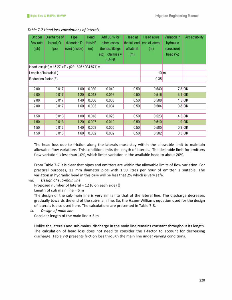
█ Egis Eau & RSPN/ BhWP Irrigation Engineering Manual
220
Table7-7Headlosscalculationsoflaterals
The head loss due to friction along the lateralsmust stay within the allowable limit tomaintain
allowableflowvariations.Thisconditionlimitsthelengthoflaterals.Thedesirablelimitforemitters
flowvariationislessthan10%,whichlimitsvariationintheavailableheadtoabout20%.
FromTable7-7itisclearthatpipesandemittersarewithintheallowablelimitsofflowvariation.For
practical purposes, 12 mm diameter pipe with 1.50 litres per hour of emitter is suitable. The
variationinhydraulicheadinthiscasewillbelessthat2%whichisverysafe.
viii. Designofsub-mainline
Proposednumberoflateral=12(6oneachside)()
Lengthofsubmainline=6m
Thedesignof the sub-main line is very similar to thatof the lateral line. Thedischargedecreases
graduallytowardstheendofthesub-mainline.So,theHazen-Williamsequationusedforthedesign
oflateralsisalsousedhere.ThecalculationsarepresentedinTable7-8.
ix. Designofmainline
Considerlengthofthemainline=5m
Unlikethelateralsandsub-mains,dischargeinthemainlineremainsconstantthroughoutitslength.
The calculation of head loss does not need to consider the F-factor to account for decreasing
discharge.Table7-9presentsfrictionlossthroughthemainlineundervaryingconditions.
Dripper
flow rate
(lph)
Discharge of
lateral, Q
(lps)
Pipe
diameter, D
(cm) (inside)
Head
loss Hf
(m)
Add 30 % for
other losses
(bends, fittings
etc) Total loss =
1.3*Hf
Head at
the tail end
of lateral
(m)
Head at u/s
end of lateral
(m)
Variation in
hydraulic
(pressure)
head (%)
Acceptability
10 m
0.35
2.00 0.017 1.00 0.030 0.040 0.50 0.540 7.3 OK
2.00 0.017 1.20 0.013 0.016 0.50 0.516 3.1 OK
2.00 0.017 1.40 0.006 0.008 0.50 0.508 1.5 OK
2.00 0.017 1.60 0.003 0.004 0.50 0.504 0.8 OK
1.50 0.013 1.00 0.018 0.023 0.50 0.523 4.5 OK
1.50 0.013 1.20 0.007 0.010 0.50 0.510 1.9 OK
1.50 0.013 1.40 0.003 0.005 0.50 0.505 0.9 OK
1.50 0.013 1.60 0.002 0.002 0.50 0.502 0.5 OK
Head loss (Hf) = 15.27 x F x (Q^1.825 / D^4.871) x L
Length of laterals (L)
Reduction factor (F)

█ Egis Eau & RSPN/ BhWP Irrigation Engineering Manual
221
Table7-8Headlosscalculationsinsub-mainline
Table7-9Headlosscalculationinmainline
Designrecommendations
Basedonthecalculationsperformedintabularformsforlaterals,sub-mainsandmainlinepipes,the
followingrecommendationsaremade.
Usebuilt-indripper/emitterwithdischargingcapacityof2litresperhour,
Use12mmdiameter(internal)lateralswithdripperspacingof30cmcentertocenter,
Use18mmdiameter(internal)pipesforboththesub-mainandmainlines,
Totalheadrequiredis0.85m(Table7-9)installtankatabout1.5mabovethegroundlevel
Dripper
flow rate
(lph)
Discharge of
lateral, Q,
(lateral) (lps)
Sub-main
flow rate
(lps)
Pipe
diameter, D
(cm)
(inside)
Head
loss Hf
(m)
Add 30 % for
other losses
(bends, fittings
etc) Total loss =
1.3*Hf
Head at
the tail end
of sub-
main (m)
Head at u/s
end of sub-
main (m)
Variation in
hydraulic
(pressure)
head (%)
Acceptability
Total number of laterals on each side 6
6 m
0.369
2.00 0.017 0.100 2.00 0.017 0.022 0.52 0.538 4.2 OK
2.00 0.017 0.100 1.80 0.029 0.038 0.52 0.554 6.8 OK
2.00 0.017 0.100 1.60 0.051 0.067 0.52 0.583 11.4 OK
2.00 0.017 0.100 1.40 0.098 0.128 0.52 0.644 19.8 Margin
1.50 0.013 0.075 2.00 0.010 0.013 0.51 0.523 2.5 OK
1.50 0.013 0.075 1.80 0.017 0.022 0.51 0.532 4.2 OK
1.50 0.013 0.075 1.60 0.030 0.039 0.51 0.549 7.2 OK
1.50 0.013 0.075 1.40 0.058 0.076 0.51 0.586 12.9 OK
Reduction factor (F)
Length of each sub-main (L)
Head loss (Hf) = 15.27 x F x (Q^1.825 / D^4.871) x L
Design flow
Q (lps)
Size
Diameter
(mm)
Design flow
Q (lps)
Size
Diameter
(mm)
Design flow
Q (lps)
Size
Diameter
(cm)
Head loss
Hf (m)
5 m
2.00 0.017 10.00 0.100 20.00 0.20 2.00 0.138 0.180 0.54 0.718 OK
2.00 0.017 12.00 0.100 18.00 0.20 1.80 0.231 0.300 0.55 0.854 OK
2.00 0.017 14.00 0.100 16.00 0.20 1.60 0.410 0.533 0.58 1.116 OK
2.00 0.017 16.00 0.100 14.00 0.20 1.40 0.786 1.022 0.64 1.666 Check
1.5 0.013 10.00 0.075 20.00 0.15 2.00 0.082 0.106 0.52 0.629 OK
1.5 0.013 12.00 0.075 18.00 0.15 1.80 0.137 0.178 0.53 0.710 OK
1.5 0.013 14.00 0.075 16.00 0.15 1.60 0.243 0.315 0.55 0.864 OK
1.5 0.013 16.00 0.075 14.00 0.15 1.40 0.465 0.604 0.59 1.190 OK
Lateral Submain Main Add 30 % for other
losses Total loss =
1.3*Hf
Head at
the tail
end of
sub-main
(m)
Head at u/s
end of sub-
main (m)
Head loss (Hf) = 15.27 x (Q 1̂.825 / D 4̂.871) x L
Length of main line (L)
AcceptabilityDripper
flow rate
(lph)
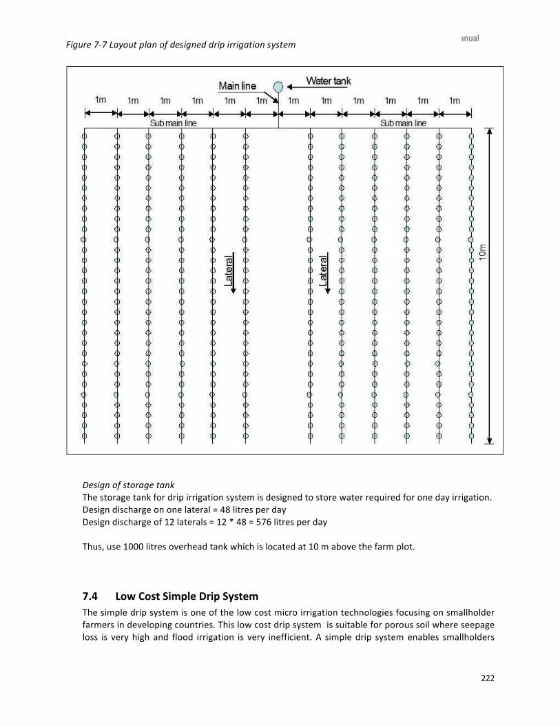
█ Egis Eau & RSPN/ BhWP Irrigation Engineering Manual
222
Designofstoragetank
Thestoragetankfordripirrigationsystemisdesignedtostorewaterrequiredforonedayirrigation.
Designdischargeononelateral=48litresperday
Designdischargeof12laterals=12*48=576litresperday
Thus,use1000litresoverheadtankwhichislocatedat10mabovethefarmplot.
7.4 LowCostSimpleDripSystem
Thesimpledripsystemisoneofthelowcostmicroirrigationtechnologiesfocusingonsmallholder
farmersindevelopingcountries.Thislowcostdripsystemissuitableforporoussoilwhereseepage
loss is veryhighand flood irrigation is very inefficient.A simpledrip systemenables smallholders
Figure7-7Layoutplanofdesigneddripirrigationsystem

█ Egis Eau & RSPN/ BhWP Irrigation Engineering Manual
223
andmarginal farmers togrowoff-seasonvegetableswithvery littlewater, enabling them toearn
incomeandalsoincreasetheirnutrientintakethroughincreasedvegetableconsumption.
The main simplifications made from the drip irrigation system are low operating head, simple
drippersandfittings,andsmallsizesystem.Astheoperatingheadcanbejust1meter,thetankcan
alsobefilledmanually.Thewaterqualityhastobefreeofanappreciableamountofsedimentand
organicmatter.Pre-filtrationisrequiredifwaterissedimentladen.Drippersaresimpleholesspaced
60 cmcenter to center ina8mmdiameterPVC flexiblepipes. Thedischargeof adripper ranges
from2.1literperhourto2.5literperhour.Thewatertankcanbeplacedonalocallymadeelevated
platformorpedestalmadeofbambooandwooden logs.Anoutletpipeconnects this tankwitha
finefilteratthebottomofthepipetoavoidblockageinthedrippipe.Outsidethetankthereisan
outletset,alevelpipetoindicatethelevelofwaterandvalvetoopenandclosethewaterflow.The
outlet is connectedwith a 14mmdiametermain linepipe,which is joined to the drip pipewith
fittingsandanadjustmentpipe.AtypicalsimpledripirrigationmodeldevelopedinNepalandIndia
ispresentedhere(Figure7-8).
Figure7-8Schematicdiagramofsimpledripirrigationsystem
IDEhasdevelopedseveralmodelsofsimpledripirrigationwithallaccessorieswhicharemarketed
atlostcostandreadyforuse(Table7-10).ThemainaccessoriesusedinSDIaregroupedintothree
parts.Thefirstgroupincludesthetankandfilterswhilethesecondgroupcomprisespipes.Thepipes
arethemainpipeline,sub-mainpipelineandlaterals.Thethirdpartcomprisesfittings,andthese
fittingsaremadeofplasticmaterial.
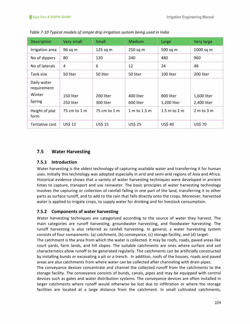
█ Egis Eau & RSPN/ BhWP Irrigation Engineering Manual
224
Table7-10TypicalmodelsofsimpledripirrigationsystembeingusedinIndia
Description Verysmall Small Medium Large Verylarge
Irrigationarea 96sqm 125sqm 250sqm 500sqm 1000sqm
Noofdippers 80 120 240 480 960
Nooflaterals 4 6 12 24 48
Tanksize 50liter 50liter 50liter 100liter 200liter
Dailywater
requirement
Winter
Spring
150liter
250liter
200liter
300liter
400liter
600liter
800liter
1,200liter
1,600liter
2,400liter
Heightofplat
form
75cmto1m 75cmto1m 1mto1.5m 1.5mto2m 2mto3m
Tentativecost US$12 US$15 US$25 US$40 US$70
7.5 WaterHarvesting
7.5.1 Introduction
Waterharvestingistheoldesttechnologyofcapturingavailablewaterandtransferringitforhuman
uses.Initiallythistechnologywasadoptedespeciallyinaridandsemi-aridregionsofAsiaandAfrica.
Historicalevidenceshowsthatavarietyofwaterharvestingtechniquesweredevelopedinancient
timestocapture,transportanduserainwater.Thebasicprinciplesofwaterharvestingtechnology
involvesthecapturingorcollectionofrainfallfallinginonepartoftheland,transferringittoother
partsassurfacerunoff,andtoaddtotherainthatfallsdirectlyontothecrops.Moreover,harvested
waterisappliedtoirrigatecrops,tosupplywaterfordrinkingandforlivestockconsumption.
7.5.2 Componentsofwaterharvesting
Water harvesting techniques are categorized according to the source of water they harvest. The
main categories are runoff harvesting, groundwater harvesting, and floodwater harvesting. The
runoff harvesting is also referred as rainfall harvesting. In general, a water harvesting system
consistsoffourcomponents:(a)catchment,(b)conveyance,(c)storagefacility,and(d)target.
Thecatchmentistheareafromwhichthewateriscollected.Itmayberoofs,roads,pavedareaslike
court yards, farm lands, andhill slopes. The suitable catchments are oneswhere surface and soil
characteristicsallowrunofftobegeneratedregularly.Thecatchmentscanbeartificiallyconstructed
byinstallingbundsorexcavatingapitoratrench.Inaddition,roofsofthehouses,roadsandpaved
areasarealsocatchmentsfromwherewatercanbecollectedafterchannelingwithdrainpipes.
Theconveyancedevicesconcentrateandchannelthecollectedrunoff fromthecatchmentstothe
storagefacility.Theconveyanceconsistsofbunds,canals,pipesandmaybeequippedwithcontrol
devicessuchasgatesandwaterdistributionsystems.Theconveyancedevicesareofteninstalledin
larger catchmentswhere runoffwould otherwise be lost due to infiltration orwhere the storage
facilities are located at a large distance from the catchment. In small cultivated catchments,

█ Egis Eau & RSPN/ BhWP Irrigation Engineering Manual
225
conveyance devices may not be necessary due to the proximity of the storage facility with the
catchment.
The storage facilities can be ofmany types including natural depressions, ponds, small reservoirs
formedeitherbyexcavatingsoilsordammingwithearthenembankment,andconcreteormasonry
walls. The storage facilities function as a buffer between a short rainfall and runoff eventswhen
naturalwaterisprovidedandlongdryperiodswhenwaterisrequired.Hence,thestoragecapacity
hastomeetthewaterdemandsduringdryperiods.
Thetarget isreferredtohereastheuseroftheharvestedwater.Dependinguponthequalityand
quantity of the available water, the targets differ from irrigation to drinking water supply and
livestockconsumption.
7.5.3 Rainwaterharvesting
Rainwater harvesting comprises the collection and storage of rainwater runoff from a variety of
surfacesfordomesticandagriculturaluses.Thetermrainwaterisoftenusedinterchangeablewith
runoff water. In general, two types of runoff harvesting are distinguished by the size of the
harvestedcatchment:microcatchmentandmacrocatchmentrunoffharvesting.
Microcatchmentreferstorooftopsystems,roadsandpavedcourtyards,whicharesuitableforthe
collectionofrunoff.Thecollectedrunoff isusuallyconveyedbyaguttersystemtotanksorponds
and used for domestic uses and for irrigation of kitchen gardens.Water can also be collected in
damsfromrainfallingonthegroundandproducingrunoff.Excavatedpondsaresimplesttobuildin
relativelyflatterrain.Thesepondsarebestsuitedtothe locationswherethedemandforwater is
small. From the point of source of feeding excavated ponds are of two types: one is fed from
surfacerunoffandtheotherisfedbygroundwateraquifers.Forthcomingheadingprovidesconcept
onthedesignofwaterstoragefacilitiessuchasponds,tanksandreservoirs.
Figure7-9Typicalexamplesofrainwaterharvestingfromrooftops
7.5.4 DesignConceptofPonds/Tanks
Themost important aspect of water harvesting ponds is to store asmuch rainwater as possible
whereitfallsduringthemonsoonandsaveitforthedryseasonfor irrigationandotheruses.The
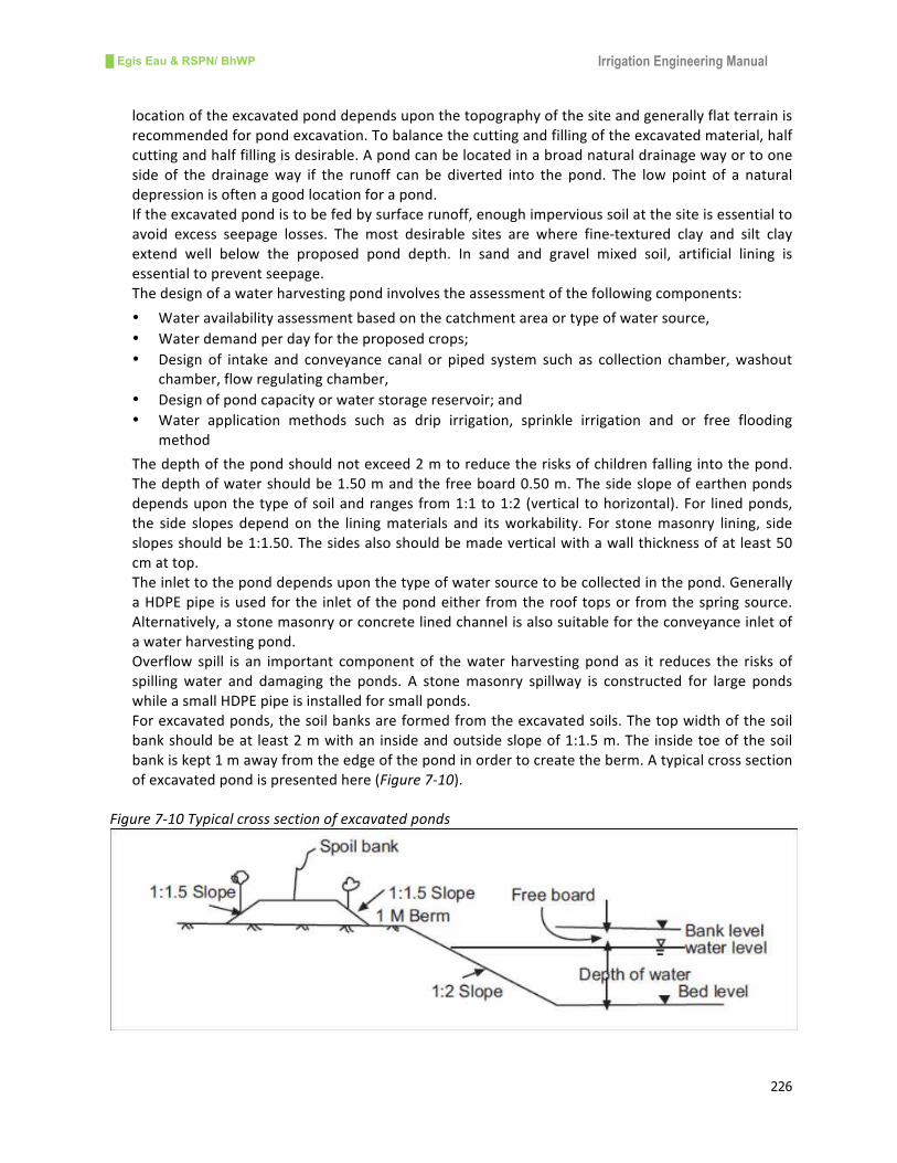
█ Egis Eau & RSPN/ BhWP Irrigation Engineering Manual
226
locationoftheexcavatedponddependsuponthetopographyofthesiteandgenerallyflatterrainis
recommendedforpondexcavation.Tobalancethecuttingandfillingoftheexcavatedmaterial,half
cuttingandhalffillingisdesirable.Apondcanbelocatedinabroadnaturaldrainagewayortoone
side of the drainageway if the runoff can be diverted into the pond. The low point of a natural
depressionisoftenagoodlocationforapond.
Iftheexcavatedpondistobefedbysurfacerunoff,enoughimpervioussoilatthesiteisessentialto
avoid excess seepage losses. The most desirable sites are where fine-textured clay and silt clay
extend well below the proposed pond depth. In sand and gravel mixed soil, artificial lining is
essentialtopreventseepage.
Thedesignofawaterharvestingpondinvolvestheassessmentofthefollowingcomponents:
• Wateravailabilityassessmentbasedonthecatchmentareaortypeofwatersource,
• Waterdemandperdayfortheproposedcrops;
• Design of intake and conveyance canal or piped system such as collection chamber,washout
chamber,flowregulatingchamber,
• Designofpondcapacityorwaterstoragereservoir;and
• Water application methods such as drip irrigation, sprinkle irrigation and or free flooding
method
Thedepthofthepondshouldnotexceed2mtoreducetherisksofchildrenfallingintothepond.
Thedepthofwatershouldbe1.50mandthefreeboard0.50m.Thesideslopeofearthenponds
dependsuponthetypeofsoilandranges from1:1to1:2 (vertical tohorizontal).For linedponds,
the side slopes depend on the liningmaterials and itsworkability. For stonemasonry lining, side
slopesshouldbe1:1.50.Thesidesalsoshouldbemadeverticalwithawallthicknessofatleast50
cmattop.
Theinlettotheponddependsuponthetypeofwatersourcetobecollectedinthepond.Generally
aHDPEpipe isusedforthe inletofthepondeither fromtherooftopsor fromthespringsource.
Alternatively,astonemasonryorconcretelinedchannelisalsosuitablefortheconveyanceinletof
awaterharvestingpond.
Overflow spill is an important component of thewater harvesting pond as it reduces the risks of
spilling water and damaging the ponds. A stonemasonry spillway is constructed for large ponds
whileasmallHDPEpipeisinstalledforsmallponds.
Forexcavatedponds,thesoilbanksareformedfromtheexcavatedsoils.Thetopwidthofthesoil
bankshouldbeat least2mwithaninsideandoutsideslopeof1:1.5m.Theinsidetoeofthesoil
bankiskept1mawayfromtheedgeofthepondinordertocreatetheberm.Atypicalcrosssection
ofexcavatedpondispresentedhere(Figure7-10).
Figure7-10Typicalcrosssectionofexcavatedponds

█ Egis Eau & RSPN/ BhWP Irrigation Engineering Manual
227
7.5.5 DesignStandards
The Local Infrastructure for Livelihood Improvement (LILI) Project under HELVETAS/Swiss
IntercooperationinNepalhasdevelopeddesignstandardsofwaterharvestingpondsforsmallscale
hillirrigationschemes(Figure7-11).Themainfeaturesofthestandardsareasfollows:
• Minimumwateravailabilityatsource:2430literperacreperday,
• Averageirrigationwaterdemand:4050literperacreperday,
• Peakdemand:threetimestheaveragedemand,
• Irrigatedareatobecoveredbyasinglepond:minimum1.2acreandmaximum5acres,
• Waterreleaseintervalfromthepond:12hours,24hours,36hoursand48hours
• Capacityofthepond:15m3,30m
3,45m
3,and60m
3
Figure7-11Standardsofwaterharvestingponds
7.5.6 Sealingthepond
Excessive seepage in ponds is generally due to a poor site where the impounding area is too
permeable to hold harvested water. A poor site is often selected due to inadequate study and
investigations.Inareaswhereasatisfactorysiteisunavailableanddemandforwaterissufficiently
high, the design of the pondmust include plans for reducing seepage by sealing the impounding
area.Therearevarioustechniquestosealthepondsandafewofthemarepresentedhereunder.
Compaction
Compactionof soils isoneof thesimplesealing techniquesof thepond if thematerials containa
widerangeofsoilparticles,includingclayandsilttoeffectaseal.Thismethodiscosteffectiveand
applicable for shallowponds. The recommended thicknessof the compacted seal is 30 cmwhere
thedepthofwaterinthepondislessthan3m.
Clayblankets
Blanketingwithclayisoneofthemethodsofreducingexcessiveseepagefromthepondswherea
high percentage of coarse-grained soil exists. The entire upstream area where water is to be

█ Egis Eau & RSPN/ BhWP Irrigation Engineering Manual
228
impoundedshouldbeblanketedwithaclay layer.Theblanketshouldconsistofawell-gradedsoil
material containing at least 20% clay. The thickness of the blanket depends upon the depth of
impoundingwater in the pond and a thickness of 30 cm is sufficient for less than 3m of water
depth.Itisessentialtoprotecttheclayblanketfromcrackingwitha30cmlayerofgraveloverthe
entiresurface.
Bentonite
Bentoniteisfine-texturedcolloidalclay.Addingbentoniteisanothermethodofreducingexcessive
seepageinsoilscontainingahighpercentageofcoarse-grainedparticlesandnotenoughclay.When
wetbentoniteabsorbsalargeamountofwaterandatcompletesaturation,itswellsasmuchas8to
20 times its original volume. It is applied with a mixture of coarse-grained material in correct
proportionsandisrecommendedtoapplyitonlesswaterfluctuatingponds.
Waterprooflinings
Usingwaterproofliningisanothermethodofreducingexcessiveseepagefrombothcoarse-grained
and fine-grained soils. Polyethylene, vinyl, butyl-rubber membrane, silpaulin, and asphalt sealed
fabric lines are gaining wide acceptance as linings for ponds. These materials virtually eliminate
seepageifproperlyinstalled.
Thinfilmsofthesematerialsarestructurallyweak,butifnotbrokenorpuncturedtheyarealmost
completelywatertight.Inaddition,asoilcementliningisalsousedinsmallscalepondliningworks.
Allplasticmembranesshouldhaveacoverofearthorearthandgravelnotlessthan15cmthickto
protect against punctures. Typical thickness of waterproof linings is presented hereunder (Table
7-11).
Table7-11Pondliningmaterials
S.N Materials Ratiobyvolume Thickness(mm)
1 Cement-termitemound 1:8 50-60
2 Cement-soil 1:8 50
3 Cement-sandmortar 1:3to1:4 50
4 Polythenesheet/Silpaulin 5
7.5.7 DesignExamplesofPond/Tank
Designexampleofsmalltank
CalculatethesizeofanexcavatedpondortankinThimpuareatosupplywaterfromrooftops.
Calculations:
• Takeannualaveragerainfallas700mm.
• Thesizeofroofforwaterharvesting =10x10=100m2,
• Annualrunoff=100x700/1000=70m3,
• Assumethereliabilityofgetting700mmisonly60%,

█ Egis Eau & RSPN/ BhWP Irrigation Engineering Manual
229
• Thevolumeofthetank=70x0.60=42m3,
• Assumethatthedepthofthetankbelowthegroundis1.2m,
• Thesurfacearearequiredfortankis42m3/1.2m=35m
2,
• Thesizeofrectangulartankbe7mx5m,

█ Egis Eau & RSPN/ BhWP Irrigation Engineering Manual
230
CHAPTER-8
8. RiverTrainingandFloodControlWorks
8.1 RiversofBhutan
Byvirtueofitshighelevationandgeographicallocation,Bhutanpossessesenormouswaterresource
potentialflowingthroughnumerouslarge,mediumandsmallrivers.Onthebasisofthenatureof
theirsourceanddischarge,theriversofBhutanmaybegroupedintothreecategories:
• Largeperennial riversoriginating fromHigherHimalayasandcarryingsignificantdischarge
throughout theyear. These large rivers includeAmochhu,WangChhu,Punatshang chhu,
Mangdechhu,andDrangmechhu.These riversarealso termedasnorth-south riversand
havemanyeast-westtributaries,
• Mediumriversoriginatingfromlowermountainsandfedbyprecipitationandgroundwater
regeneration. Although these rivers are also perennial, they are characterized by a wide
seasonalfluctuationofdischarge.TheseriversincludeJaldhaka,Maochhu,Nyera-ama,and
Dhansari,and
• Smallriversoriginatingfromlowermountainfoothillsandfedbymonsoonrainfall.Alarge
number of such small rivers are seasonal with little or no flow during the non-monsoon
season.Theseriversare locatedmostly in threesoutherndistrictsofSamtse,Sarpangand
SamdrupJonkhar.
Thelargeriversprovidewaterforhydropowergeneration,wasteassimilation,tourismandecology
andnotmuchfor irrigation.2Mediumriversandtributariesof largeriversare themost important
riversfromawaterutilizationpointofview,whichhaveplentyofcultivatedlands.Smallriversthat
originatefromsouthernfoothillsarealmostdrymostoftheyearbutcharacterizedbyflashfloods
duringthemonsoonseason.
Due to the steep topographic and fragile geological conditions, river banks are eroding and their
coursesarechangingfromtimetotimealongwiththeirflowpattern.Everyyear,significantdamage
occursanda lotofprivateandpublicpropertyandagricultural landarebeingwashedaway,with
thelossofhumanlives,alongtheseriverbanks.Hence,itisimportanttocontrolthefloodandtrain
theseriverstoprotectproperty,landandhumanlivesfrombeingfurtherdamagedandultimatelyto
supportthenationaleconomicgrowthofthecountry.
8.2 Floods
8.2.1 Typesoffloods
A flood is a condition of toomuch water and results when a river overflows its banks. In other
words,afloodistheresultofanunusuallyhighstageofariverwhenthestreamchannelsbecome
filledandwaterspillsoverthebanks.InSouthAsia,floodsoccurduetohighintensityrainfallduring
themonsoon.Amaximumfloodofariverisoneofthemostimportantaspectsofaflowhydrograph
concernedwiththedesignofhydraulicstructures,includingrivertrainingworks.Therearevarious
typesoffloods,themostcommontypesarepresentedhere:
2ParochhuisbeingusedforirrigationinParovalley
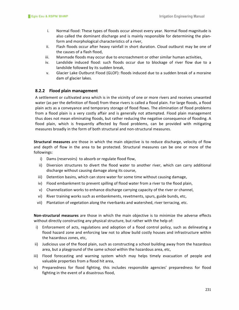
█ Egis Eau & RSPN/ BhWP Irrigation Engineering Manual
231
i. Normalflood:Thesetypesoffloodsoccuralmosteveryyear.Normalfloodmagnitudeis
alsocalledthedominantdischargeandismainlyresponsiblefordeterminingtheplan-
formandmorphologicalcharacteristicsofariver,
ii. Flashfloodsoccurafterheavyrainfall inshortduration.Cloudoutburstmaybeoneof
thecausesofaflashflood,
iii. Manmadefloodsmayoccurduetoencroachmentorothersimilarhumanactivities,
iv. Landslide induced flood: such floods occur due to blockage of river flow due to a
landslidefollowedbyitssuddenbreak,
v. GlacierLakeOutburstFlood(GLOF):floodsinducedduetoasuddenbreakofamoraine
damofglacierlakes.
8.2.2 Floodplainmanagement
Asettlementorcultivatedareawhichisinthevicinityofoneormoreriversandreceivesunwanted
water(asperthedefinitionofflood)fromtheseriversiscalledafloodplain.Forlargefloods,aflood
plainactsasaconveyanceandtemporarystorageoffloodflows.Theeliminationoffloodproblems
froma floodplain is a very costly affair and is generallynot attempted. Floodplainmanagement
thusdoesnotmeaneliminatingfloods,butratherreducingthenegativeconsequenceofflooding.A
flood plain, which is frequently affected by flood problems, can be provided with mitigating
measuresbroadlyintheformofbothstructuralandnon-structuralmeasures.
Structuralmeasuresare those inwhich themainobjective is to reducedischarge, velocityof flow
and depth of flow in the area to be protected. Structural measures can be one or more of the
followings:
i) Dams(reservoirs)toabsorborregulatefloodflow,
ii) Diversion structures to divert the flood water to another river, which can carry additional
dischargewithoutcausingdamagealongitscourse,
iii) Detentionbasins,whichcanstorewaterforsometimewithoutcausingdamage,
iv) Floodembankmenttopreventspillingoffloodwaterfromarivertothefloodplain,
v) Channelizationworkstoenhancedischargecarryingcapacityoftheriverorchannel,
vi) Rivertrainingworkssuchasembankments,revetments,spurs,guidebunds,etc,
vii) Plantationofvegetationalongtheriverbanksandwatershed,riverterracing,etc.
Non-structuralmeasuresare those inwhich themainobjective is tominimize theadverseeffects
withoutdirectlyconstructinganyphysicalstructure,butratherwiththehelpof:
i) Enforcementof acts, regulations andadoptionof a flood control policy, suchasdelineatinga
floodhazardzoneandenforcinglawnottoallowbuildcostlyhousesandinfrastructurewithin
thehazardouszones,etc,
ii) Judicioususeofthefloodplain,suchasconstructingaschoolbuildingawayfromthehazardous
area,butaplaygroundofthesameschoolwithinthehazardousarea,etc,
iii) Flood forecasting and warning system which may helps timely evacuation of people and
valuablepropertiesfromafloodhitarea,
iv) Preparedness for flood fighting, this includes responsible agencies’ preparedness for flood
fightingintheeventofadisastrousflood,

█ Egis Eau & RSPN/ BhWP Irrigation Engineering Manual
232
v) Floodproofing-thismeanswaysoflivingwithfloodswithoutallowingmuchdamagetolifeand
property.Storingfoodgrainsinanelevatedstructure,raisingtheplinthheightofabuilding,etc.
aresimpleexamplesoffloodproofing.
Hence, flood plain management considers the integrated approach of all engineering,
bioengineering, and administrative measures for mitigating losses due to flooding in a
comprehensivescale.
8.2.3 FloodproneareasinBhutan
LocatedintheHimalayanregionandinproximitytotheBayofBengal,Bhutanexperiencesahigher
incidence of natural disasters like earthquakes, flash floods,wind storms, fires and landslides. Of
thesenaturaldisasters,floodsareamongthemostprominentandreoccurringdisastersinBhutan.
The main causes of the floods are heavy rainfall, wind storms and Glacier Lake Outburst Flood
(GLOF).AllofthesouthernfoothillsborderingIndiaarehighlypronetoflashfloodswhichcauseloss
ofhumanlives,properties,lossofcultivatedlands,anddamagetonaturalenvironment.Inaddition,
past eventsofGLOFhad caused significantdamages to lives andproperties inPunakha-Wangdue
valley.Bhutanhas677glaciersand2,674glacierlakesoutofwhich25arepotentiallydangerous.
AccordingtothepastrecordsofGLOF,Lunanaisoneofthepotentialglacierlakesthathadcaused
floodinginBhutan.TherewerefourfloodeventsfromLunanaglacierin1957,1960,1968and1994.
Themost dangerous flood eventwas October 1994 floodwhich damaged significant amounts of
property,livesandcultivatedlands.
Thefloodseventsof2000,2004,2009and2011arerecordedfloodeventscausedbyheavyrainfall
andwindstorms.TheareasinandaroundthePasakhaindustrialareainChhukhaDzongkhagwere
severelyaffectedbytheflashfloodsof2000.Theareahadexperiencedheavyrainfallofmagnitude
1,812mminthemonthofAugust.ThehighestamountofrainfallrecordedinadayatTalawas400
mminthemonthofAugust2000.Thishighamountofrainfallexperiencedbythisareaisthemain
factor forthehigh incidenceof flashfloodsanderosion.BarsaandSigyeRivers,whichflowinthe
Pasakhaarea,swell toanunbelievablemagnitudeandhavedamaged lives,propertyand lands. In
addition,thenationalhighwaytoThimpufromPhuentsolingwasclosedforamonthduetoerosion
andlandslides.
In2004,heavyrainfalloccurred inthesixeasternDzongkhags,contributingtoheavyfloodevents.
Themost affectedwere Trashigang, Trashiyangste and Samdrup Jongkhar Dzongkhags, where 91
peoplelosttheirlives,housesandlandswerewashedaway,publicinfrastructureandserviceswere
damaged,andconsequentlythewholesocialandeconomiclifeoftheareawasimpaired.
Similarly, inMay2009heavy floodingoccurred inBhutandue to theunprecedentedCycloneAila
originatingintheBayofBengal.Thisfloodeventhit17Dzongkhagsandcausedsignificantdamage
tolives,property,cultivatedlands,andpublicandcommunityinfrastructure.
Based on past experience, the most flood prone areas are Punakha-Wangue valley from
Punatsangchhuriver,Pashakha-PhuentsolingareafromTorsa,BarsaandSingyerivers,Sarpangarea
fromSarpangriver,GelephuareafromMaoanditstributaryrivers,HaatownfromHaaChhu,and
ParotownfromParoChhu.Inaddition,Daragaon,Hawazhori,LhamoizingkhaBazaarandMajigaon
arefloodproneareasalongtherightbankofSunkoshriverinDaganaDzongkhag.
Examplesof river trainingworks inBhutanare thePochhuriverprotectionworks,PunakhaDzong
protectionworks,Haatownprotectionworks,SetikhareKholachannelization(Figure8-1)etc.
█ Egis Eau & RSPN/ BhWP Irrigation Engineering Manual
233
Figure8-1ExamplesofrivertrainingworksinBhutan
Haatownprotectionworks SetikhareKhola,Gelephu
8.3 RiverTrainingWorks
8.3.1 Introduction
River training deals with a series of works that include the construction of structures along and
acrossarivertofulfillspecialobjectives.Thesestructuresincludetheconstructionofdikesalongthe
banksoftherivertocontrolfloodsandoftransversalwalls(groynesspurs,studs,spikesetc)tolead
flowinadefinedpath.Likewise,rivertrainingmaybeaccomplishedthoughdredgeoperationsorby
bounding the flowwidth fornavigation, thediversionof flowwater into secondary channels, and
the construction of shortcut channels in themain river path. Hence, themain objectives of river
trainingmeasuresare:
• Topasshighflooddischargesafelyandquicklythroughthereach,
• Totransportsedimentloadefficiently,
• Toallowminimumwaterdepthfornavigation,
• Tofixcertaindirectionofflow,and
• Tomaintaintheriverintherequiredcondition
8.3.2 Typesofrivertrainingworks
Thefollowingarethecommonmethodsofrivertrainingandfloodcontrolmeasures,theapplication
ofwhichisdeterminedthroughaspecificdesignprocess:
• Marginalembankmentsorleveesandguidebunds,
• Permeableandimpermeablespursorgroynes,
• Bankpitchingandrevetmentwithlaunchingaprons,
• Cut-offs

█ Egis Eau & RSPN/ BhWP Irrigation Engineering Manual
234
8.3.3 Embankmentbundsandguidebunds
An embankment is a man-made bank to raise the natural banks in order to prevent flooding.
Embankmentsareusuallyconstructedusinglocalsoilmaterial.
Guide banks are used to confine the flow to a single channel, to improve the distribution of
discharge across the weir, barrage or bridge, to control the angle of attack, to control meander
patterns, and toprevent erosionof embankments. Two guidebanks are generally requiredwhen
thewaterwayopening is located in themiddleofawide flood-plainorbraidedstreamwhere the
directionofthemainflowcanshiftfromsidetoside. Asingleguidebankmaybesufficientwhen
thestreamisconfinedtoonesideofavalley,orwhereadvantagecanbetakenofanaturalbank,
whichisresistanttoerosion,ononeside.
The minimum width between guide banks is determined with consideration of the required
waterwayopeningareathroughthestructure.Thewaterwayforregimewidthshouldbe:
QdCWs = whereQdisthedesignflooddischargeappropriatetothedesignreturnperiodflood,
Cisthecoefficientthatrangesfrom3.3to4.9
ThechoiceofreturnperiodforQd isrelatedtotheimportanceofthestructuretobeprotectedor
designed,theriskofout-flankingduringriverfloods,andtheavailabilityoffloodways.Thechoiceof
returnperiodisdiscussedinChapter-3HydrologyandAgro-meteorology.
Majordesignfactorsofguidebundsare:
• Orientationtothewaterways,
• Planshape-straight,curvedandhockeyshaped,
• Upstreamanddownstreamlengths:u/s-¾ofwaterwaywidthandd/s¼ofwaterway
width(Figure8-2),
• Embankmentcrosssectionalshape(Figure8-3),
Guide banks should normally extend above the design high-water level, with an appropriate
freeboardallowance:theirmostimportantroleistoguidefloods.Theelevationofthedead-water
pondtrappedbehindtheguidebankswillbehigherthanthefloodstageattheweirbyanamount
approximatelyequal to thenormal fallalongthechannel inside theguidebanks,plus thevelocity
headinthecontractedwaterway.

█ Egis Eau & RSPN/ BhWP Irrigation Engineering Manual
235
Figure8-2LengthandPlanshapeofGuideBanks
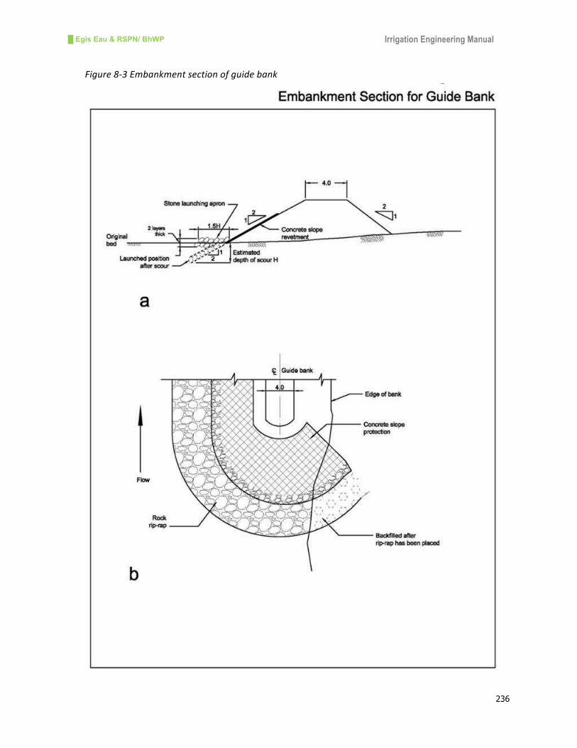
█ Egis Eau & RSPN/ BhWP Irrigation Engineering Manual
236
Figure8-3Embankmentsectionofguidebank
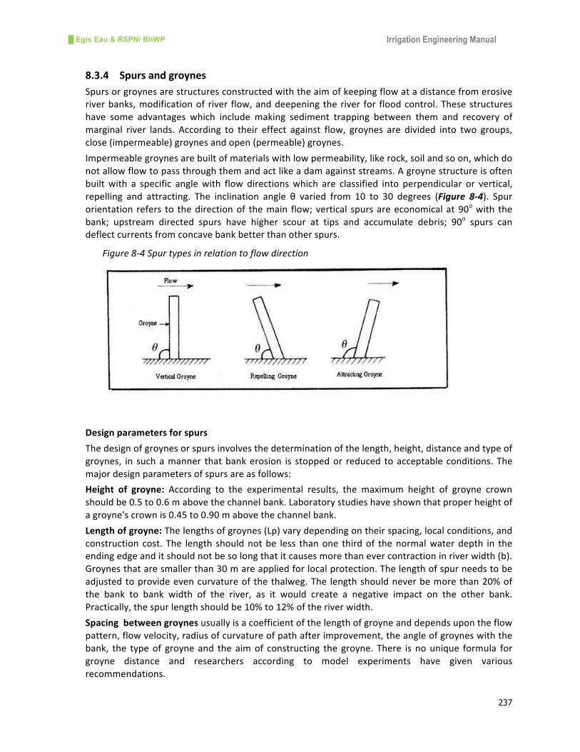
█ Egis Eau & RSPN/ BhWP Irrigation Engineering Manual
237
8.3.4 Spursandgroynes
Spursorgroynesarestructuresconstructedwiththeaimofkeepingflowatadistancefromerosive
riverbanks,modificationof river flow,anddeepeningtheriver for floodcontrol.Thesestructures
have some advantages which include making sediment trapping between them and recovery of
marginal river lands. According to their effect against flow, groynes are divided into two groups,
close(impermeable)groynesandopen(permeable)groynes.
Impermeablegroynesarebuiltofmaterialswithlowpermeability,likerock,soilandsoon,whichdo
notallowflowtopassthroughthemandactlikeadamagainststreams.Agroynestructureisoften
builtwith a specific anglewith flow directionswhich are classified into perpendicular or vertical,
repelling and attracting. The inclination angle θ varied from 10 to 30 degrees (Figure 8-4). Spur
orientation refers to thedirectionof themain flow;vertical spursareeconomical at90owith the
bank; upstream directed spurs have higher scour at tips and accumulate debris; 90o spurs can
deflectcurrentsfromconcavebankbetterthanotherspurs.
Figure8-4Spurtypesinrelationtoflowdirection
Designparametersforspurs
Thedesignofgroynesorspursinvolvesthedeterminationofthelength,height,distanceandtypeof
groynes, in suchamanner thatbankerosion is stoppedor reduced toacceptable conditions.The
majordesignparametersofspursareasfollows:
Height of groyne: According to the experimental results, the maximum height of groyne crown
shouldbe0.5to0.6mabovethechannelbank.Laboratorystudieshaveshownthatproperheightof
agroyne'scrownis0.45to0.90mabovethechannelbank.
Lengthofgroyne:Thelengthsofgroynes(Lp)varydependingontheirspacing,localconditions,and
construction cost. The length shouldnotbe less thanone thirdof thenormalwaterdepth in the
endingedgeanditshouldnotbesolongthatitcausesmorethanevercontractioninriverwidth(b).
Groynesthataresmallerthan30mareappliedforlocalprotection.Thelengthofspurneedstobe
adjustedtoprovideevencurvatureof thethalweg.The lengthshouldneverbemorethan20%of
the bank to bank width of the river, as it would create a negative impact on the other bank.
Practically,thespurlengthshouldbe10%to12%oftheriverwidth.
Spacingbetweengroynesusuallyisacoefficientofthelengthofgroyneanddependsupontheflow
pattern,flowvelocity,radiusofcurvatureofpathafterimprovement,theangleofgroyneswiththe
bank, the typeof groyne and the aimof constructing the groyne. There is nounique formula for
groyne distance and researchers according to model experiments have given various
recommendations.
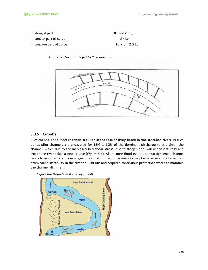
█ Egis Eau & RSPN/ BhWP Irrigation Engineering Manual
238
Instraightpart3Lp<d<5Lp
Inconvexpartofcurved=Lp
Inconcavepartofcurve2Lp<d<2.5Lp
Figure8-5Spurangle(φ)toflowdirection
8.3.5 Cut-offs
Pilotchannelsorcut-offchannelsareusedinthecaseofsharpbendsinfinesand-bedrivers.Insuch
bends pilot channels are excavated for 15% to 30% of the dominant discharge to straighten the
channel,whichduetotheincreasedbedshearstress(duetosteepslope)willwidennaturallyand
theentirerivertakesanewcourse(Figure8-6).Aftersomefloodevents,thestraightenedchannel
tendstoassumeitsoldcourseagain.Forthat,protectionmeasuresmaybenecessary.Pilotchannels
oftencauseinstabilityintheriverequilibriumandrequirescontinuousprotectionworkstomaintain
thechannelalignment.
Figure8-6Definitionsketchofcut-off
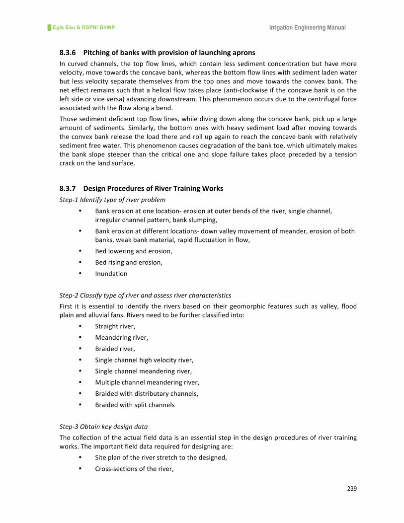
█ Egis Eau & RSPN/ BhWP Irrigation Engineering Manual
239
8.3.6 Pitchingofbankswithprovisionoflaunchingaprons
In curved channels, the top flow lines,which contain less sediment concentrationbut havemore
velocity,movetowardstheconcavebank,whereasthebottomflowlineswithsedimentladenwater
but lessvelocity separate themselves fromthe toponesandmove towards theconvexbank.The
neteffectremainssuchthatahelicalflowtakesplace(anti-clockwiseiftheconcavebankisonthe
leftsideorviceversa)advancingdownstream.Thisphenomenonoccursduetothecentrifugalforce
associatedwiththeflowalongabend.
Thosesedimentdeficienttopflowlines,whiledivingdownalongtheconcavebank,pickupalarge
amountof sediments. Similarly, thebottomoneswithheavy sediment loadaftermoving towards
theconvexbankreleasetheloadthereandrollupagaintoreachtheconcavebankwithrelatively
sedimentfreewater.Thisphenomenoncausesdegradationofthebanktoe,whichultimatelymakes
the bank slope steeper than the critical one and slope failure takes place preceded by a tension
crackonthelandsurface.
8.3.7 DesignProceduresofRiverTrainingWorks
Step-1Identifytypeofriverproblem
• Bankerosionatonelocation-erosionatouterbendsoftheriver,singlechannel,
irregularchannelpattern,bankslumping,
• Bankerosionatdifferentlocations-downvalleymovementofmeander,erosionofboth
banks,weakbankmaterial,rapidfluctuationinflow,
• Bedloweringanderosion,
• Bedrisinganderosion,
• Inundation
Step-2Classifytypeofriverandassessrivercharacteristics
First it is essential to identify the rivers based on their geomorphic features such as valley, flood
plainandalluvialfans.Riversneedtobefurtherclassifiedinto:
• Straightriver,
• Meanderingriver,
• Braidedriver,
• Singlechannelhighvelocityriver,
• Singlechannelmeanderingriver,
• Multiplechannelmeanderingriver,
• Braidedwithdistributarychannels,
• Braidedwithsplitchannels
Step-3Obtainkeydesigndata
Thecollectionoftheactualfielddataisanessentialstepinthedesignproceduresofrivertraining
works.Theimportantfielddatarequiredfordesigningare:
• Siteplanoftheriverstretchtothedesigned,
• Cross-sectionsoftheriver,
█ Egis Eau & RSPN/ BhWP Irrigation Engineering Manual
240
• Longitudinalprofileoftheriver,
• Bedandbankmaterialsamples,
• Dischargemeasurementifpossible,
• Highfloodmarks,
• Previousstructuralmeasures
Inadditiontofielddata,secondarydataalsoareessentialforthedesign.Theseareflowrecordsof
the riverandcatchmentdetails. It is alsonecessary toassess thepast interventionsmade in that
stretchoftheriverandtheirperformancewithrespecttorivertraining.
Step-4Assessalternativesforsolvingriverproblems
Basedontheproblemidentificationandassessmentofrivercharacteristics,itisessentialtopropose
alternativesforsolvingtheriverproblems.Thealternativesmaybe:
• Holdtheriverinexistingchannel(bankerosionatonelocation),
• Relocatemainflowchannel(bankerosionatmanylocations,braidedchannel),
• Holdverticalpositionofriverbed(bedlowering,bankslumping)
Step-5Quantifydesignparameters
Therequireddesignparametersare:
• Designdischarge(floodreturnperiods,50yearsreturnperiodmeans(1/50)2%risk),
o Frequencyanalysisforgaugedriver,
o Regionalfloodfrequencyrelationshipsifavailable,
o Highwatermarks,
o Bankfulldischarge-Manning’sequation
• Flowvelocities,
o Averagevelocity,Vm=designdischarge/cross-sectionarea
o LocalvelocitiesatrivertraininglocationsV1=2/3Vm,4/3Vm,Vm
• Scourmagnitude,
Scouristheremovalofsoilparticlesbycurrentorlocalizederosionofbedmaterial.Scourdepthis
themeanhydraulicdepthmultipliedbyascour factor.Thescour factor isdifferent fora rangeof
conditionssuchasbends,abruptobstructions,constrictions,bridgepiers,spurs,etc.
• Stablewaterways,
Lacey’swaterwayiscommonlyusedforestimatingstablewaterwaysattherivertraininglocations.
Step-6Selecttypesofrivertrainingmeasures
• Structuralmeasures:
o Bankrevetments-riprap,gabionrock-filled,bambooandsandbags,
o Spurs-roundnose,hockeytype,t-type,slopingandJ-spur,
o Embankmentwithstuds,
o Canalizationofriveralignment,
o Bioengineeringmeasures
• Non-structuralmeasures:
o Preparedness,

█ Egis Eau & RSPN/ BhWP Irrigation Engineering Manual
241
o Reliefactivities,
o Landusezoning,
o Floodforecasting,
o Floodwarningandevacuation
Step-7Assessconstructionprocedures
• Gabionstructures,
• Sandbagfillinginnylonnets,
• Layoutofstructures,
• Workingmethodsunderwater,
• Diversionanddewatering,
• Bamboo/timberpiledriving,
• People’sparticipation
Step-8Identifymaintenanceprogram
Amonitoringandmaintenanceprogramisessentialtoensurethattheworksperformasdesigned.
Thecostofeffectivemaintenanceisusuallysmallerthanthecapitalcostofreplacingrivertraining
works that faileddue toa lackofmaintenance.Regularmonitoringandperiodicmaintenanceare
essentialpartsofrivertraining.
Step-9Estimatecostofrivertrainingmeasures
The cost of river trainingmeasures is computed based on an estimation of each identifiedwork
items.TheanalysisofeachitemisderivedfromtheBhutanScheduleRatesupdatedeveryyearby
theMinistryofWorksandHumanSettlement.
Step-10Assesssocio-economicbenefitsoftheproposedmeasures
The river training benefits are the value of losses or damage that would have occurred without
trainingmeasures.Thespecificbenefitsasanticipatedwouldbe:
§ Increaseincropyields,
§ Increaseincroparea,
§ Increaseinpriceofland,
§ Savingintransportationexpenses
Besidesthebenefitstobeassessedasabove,therewouldbemanyotherbenefitsfromrivercontrol
and training measures such as employment opportunities, increased production from reclaimed
land,humansafety,etc.
Step-11Assesseconomicevaluation
Theeconomicevaluationoftherivertrainingmeasuresiscarriedoutonthreeparameters.
§ Benefitcostratio,
§ Netpresentvalue,

█ Egis Eau & RSPN/ BhWP Irrigation Engineering Manual
242
§ Economicinternalrateofreturn
8.4 BankProtectionWorks
8.4.1 GeneralConcept
Flood problems are mainly of two types: bank erosion and inundation. Bank erosion is more
pronounced in Bhutan and itwill be dealtwith inmoredetail hereunder. Before considering any
bankprotectionmeasure,itisnecessarytounderstandhowbankerosiontakesplaceinanalluvial
river.Bankmaterialsmaybecohesive,non-cohesiveandcomposite.Bankmaterial iscarriedaway
bytheriverandthephenomenonisrepeatedinthenewslopeline.Thus,thebankretreatsaslong
asthehydraulicandgeo-technicalconditionsallowittodoso.Massfailureofbankscanoccurdue
tobankslopegeometry,surfaceandgroundwaterflowregime,surchargeloading,tensioncracking
and vegetation. These failuresmay be shallow failure, planar failure, surface erosion failure, and
deepseatedrotationalfailure.Atypicalbankfailureispresentedhere(Figure8-7).
Figure8-7Typicalbankfailure
8.4.2 Methodsofbankprotection
The type of bank protectionworks or revetmentworks to be usedwill depend upon the cost of
materials,durability,safetyandappearance.Themostcommonlyusedtypesofflexiblerevetment
includestonerip-rap,gabions,wiremeshovera layerofstones,baggedconcrete,andarticulated
concreteslabs.Attentionisgivenfirsttostonerip-rapbecauseofitsconsiderableadvantagesover
othertypes.Riprapisflexibleandisnotimpairedbyslightmovementoftheembankmentresulting
fromsettlement.
Rip-rapProtection
The term rip-rap implies the use of irregular stones provided to meet a fairly close grading
specification.Inmostsituationscoveredinstandardmanualsanddesigns,rip-rapcomesfromthe
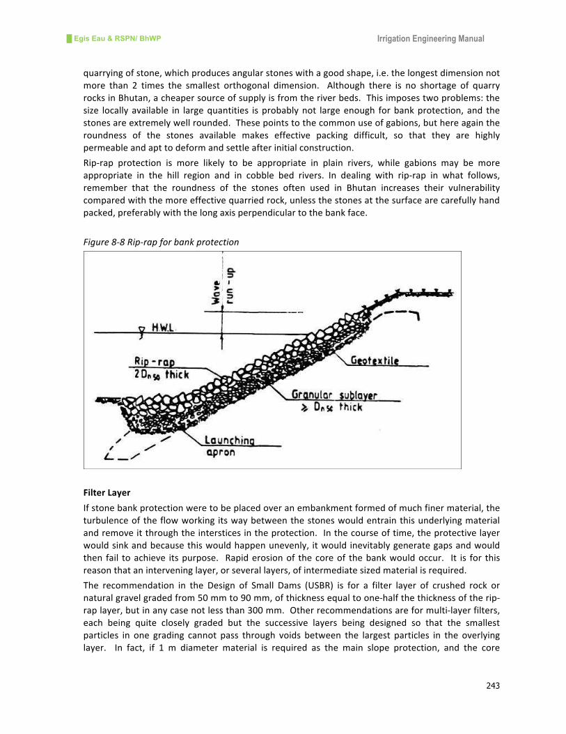
█ Egis Eau & RSPN/ BhWP Irrigation Engineering Manual
243
quarryingofstone,whichproducesangularstoneswithagoodshape,i.e.thelongestdimensionnot
more than 2 times the smallest orthogonal dimension. Although there is no shortage of quarry
rocksinBhutan,acheapersourceofsupplyisfromtheriverbeds.Thisimposestwoproblems:the
size locally available in largequantities isprobablynot largeenough forbankprotection, and the
stonesareextremelywellrounded.Thesepointstothecommonuseofgabions,buthereagainthe
roundness of the stones available makes effective packing difficult, so that they are highly
permeableandapttodeformandsettleafterinitialconstruction.
Rip-rap protection is more likely to be appropriate in plain rivers, while gabions may be more
appropriate in the hill region and in cobble bed rivers. In dealing with rip-rap in what follows,
remember that the roundness of the stones often used in Bhutan increases their vulnerability
comparedwiththemoreeffectivequarriedrock,unlessthestonesatthesurfacearecarefullyhand
packed,preferablywiththelongaxisperpendiculartothebankface.
Figure8-8Rip-rapforbankprotection
FilterLayer
Ifstonebankprotectionweretobeplacedoveranembankmentformedofmuchfinermaterial,the
turbulenceoftheflowworking itswaybetweenthestoneswouldentrainthisunderlyingmaterial
andremoveitthroughtheintersticesintheprotection.Inthecourseoftime,theprotectivelayer
wouldsinkandbecausethiswouldhappenunevenly, itwould inevitablygenerategapsandwould
then fail toachieve itspurpose. Rapiderosionof thecoreof thebankwouldoccur. It is for this
reasonthataninterveninglayer,orseverallayers,ofintermediatesizedmaterialisrequired.
The recommendation in the Design of Small Dams (USBR) is for a filter layer of crushed rock or
naturalgravelgradedfrom50mmto90mm,ofthicknessequaltoone-halfthethicknessoftherip-
raplayer,butinanycasenotlessthan300mm.Otherrecommendationsareformulti-layerfilters,
each being quite closely graded but the successive layers being designed so that the smallest
particles in one grading cannot pass through voids between the largest particles in the overlying
layer. In fact, if 1 m diameter material is required as the main slope protection, and the core

█ Egis Eau & RSPN/ BhWP Irrigation Engineering Manual
244
material is fine sand or silty soil, amulti-layer filter would be essential. It is normal practice to
replacethefinestlayerinsuchsituationswithageotextile(filterfabric).
UseofGabions
Gabionsare themostcommonlyusedbankprotectionmeasures.Theadvantageofgabionsis that
smallerstonescanbeusedwithintheconfinesofawirecrate.Thus,apossibledesignmethodisto
comparetheirstabilityinflowingwaterwiththatofthestonesbythemselves.Theindicationsare
thatthestoneswithinagabiongainthestabilityofstonesofdoubletheirdiameterthatarenotso
encased,providedtheFroudenumberoftheflowis lessthan1.5.ForhigherFroudenumbersthe
advantageisless.
ToeProtection
Thetoeofthebankprotectionmeasuresisessentialtoprotectfromunderminingbyscour,whichis
causedbystreamfloworseepage.Toeprotectioncanbeachievedintwoways:
• Byconstructingacut-offtowithstandscour,
• Byprovidingapronofflexibleprotectionacrossthebedfromtoeofbank(Figure8-9),
Figure8-9Basictypesoftoeprotection
8.4.3 Designprocedureofrevetment
Revetmentandanassociated launchingapron is themost common typeofbankprotectionwork
beingadoptedindevelopingcountries.
Thethicknessofrevetmentisgivenby
Dn=ΦcKTKh0.035u2/(ΔmKsθc2g)
Where,

█ Egis Eau & RSPN/ BhWP Irrigation Engineering Manual
245
Φc=slopestabilityfactor=0.50forgabionmattress,and
Φc=0.75forstoneriprap(withoutgabion)
KT=turbulencefactor
TakeKT=1fornormalturbulenceasinstraightreachoftheriver
KT = 1.5 for increased turbulence and non-uniform flow as in gentle concave bends, in the
downstreamofstillingbasins,nearthebridgesiteswithpiers,etc.
KT=2.0forhighturbulenceasinsharpconcavebends
KT=3forextremelyhighturbulenceasinjetimpact
Kh=depthandvelocitydistributionfactorgivenby=2[log(12h/Kr)+1]-2
Where, Kr = mean equivalent roughness height (take Kr = thickness of largest particle or the
thicknessofrevetmentitself)
Δm=relativedensityofgabionmattress=(γs-γf)x(1-n)/γf
Where,n=porosityofgabionmattress=0.4
u=averagevelocityofflow
γsandγfareunitweightofstoneandwaterinN/m3
Ks=slopereductionfactorgivenby,
φ
α2
2
1Sin
SinKs=
Whereα=riverbankslopeangleand
φ=angleofreposeofstones(about360)
θc=criticaldimensionlessshearstressandequalsto0.06forgabionmattress,and0.035forstone
riprap
DesignofLaunchingApron
Lacey'ssiltfactorf= )(d1.76 50 mm
Whered50isthemediandiameteroftheriverbedmaterial,whichmeanstheparticlesizeinmm
correspondingto50%intheparticlesizedistributioncurve,
ScourdepthcanbepredictedbyLacey'sformula,whenthereisnoconstriction.Normalscourdepth
measuredfromtheHFLisgivenby,
R=0.47x(Q/f)1/3whereQisthedischargeinm3/s,fisthesiltfactor
AdopttheanticipatedscourdepthbelowHFL=1.25*R,forstraightbend,
1.5*Rformoderatebend,
1.75*Rforseverebend,and
2.0*Rforrightangledbend
Afterknowingthepredictedscourlevelduringhighflood,assumethattheapronwillbelaunchedto
thepredicteddepthbelowthe toeof the revetmentor riverbankata slopeof1:2 (V:H).For that
inclinedslope,itisnecessarytoprovidelaunchingapron.
(i)Incaseofboulderfilledgabionmattresslaunchingapron,alwaysprovide
█ Egis Eau & RSPN/ BhWP Irrigation Engineering Manual
246
Lengthoftheapron(whichistobeplacedhorizontallyattheriverbedlevel) =
inclinedlengthofthelaunchingslope
=[(riverbedlevel–predictedscourlevel)*√5]
Providethicknessoftheapron=thicknessoftherevetment
Nevershortentheapronlengthbyincreasingthethicknessincaseofgabionapron.
(ii)Incaseoflaunchingapronoflooseboulders,
Compute per unit volume of the boulders required by multiplying the length and thickness
computedasincaseofgabionlaunchingapronabove.
Increase thevolumeby25% toaccount for theuneven thicknesswhile rollingdown theboulders
alongthescourslope
Providetheapronbydumpingbouldersinthetrenchalongthetoeoftheriverbankordikeslopeso
thatthefillvolumeisequaltothevolumecomputedabove.
8.5 MathematicalModelsforriverstudies
Thedesignofrivertrainingandfloodcontrolworksarecarriedoutwiththehelpofmathematical
models which represent hydraulic and hydrologic parameters of the river. The most common
computermodels are HECHMS, HEC RAS,MIKE BASIN,MIKE 11, andMIKE FLOOD. Results from
thesemodelsareappliedforstudyingtheextentoffloodareasandinfluenceofcontractioninthe
river sections resulting from the construction of flood control and river training measures and
extractwaterlevelchanges.
TheHEC-RAS(HydrologicEngineeringCenterRiverAnalysisSystem)modelingsystemispartofthe
U.S.ArmyCorpsofEngineers“NextGeneration”software.DevelopedattheHydrologicEngineering
Center, thesoftwarepackage incorporatesvariousaspectsofhydraulicmodeling, includingsteady
and unsteady flow. HEC-RAS applications include one-dimensional modeling of river channels,
streams, and floodplains, from single reaches to complex stream networks. Bridge and culvert
geometry can be defined and added, as well as inline and lateral structures, such as weirs and
levees.HEC-RAShasroutinesforimportingUNETdataaswellasdatafromothersources.HEC-RAS
operatesintheMicrosoftWindowsenvironmentandusesagraphicaluserinterfacefordataentry,
graphics, and display of program results. It uses implicit finite-difference schemes for solving
unsteadyflowequations.
SWAT(SoilWaterAssessmentTool)isariverbasinscalehydrologicmodeldevelopedtoquantifythe
impactof landmanagementpractices in largeandcomplexwatersheds.Themaincomponentsof
SWAT include weather, surface runoff, return flow, percolation, evapo-transpiration, reservoir
storage,cropgrowthandirrigation,groundwaterflow,andwatertransfer.SWATisapublicdomain
model actively supported by the USDA Agricultural Research Service at the Grassland, Soil and
WaterResearchLaboratoryTemple,Texas.
MIKE BASIN developed by DHIWater and Environment, is a mathematical representation of the
riverbasinencompassingtheconfigurationofthemainriversandtheirtributaries,thehydrologyof
thebasininspaceandtime,existingaswellaspotentialmajorschemes,andtheirvariousdemands
onwater.MIKEBASINisstructuredasanetworkmodelinwhichtheriversandtheirmaintributaries
arerepresentedbyanetworkconsistingofbranchesandnodes.ItisanextensiontoArcViewGIS,
suchthatexistingGISinformationcanbeincludedinthewaterresourcessimulations.
MIKE 11 developed by DHI (Danish Hydraulic Institute) Water and Environment, is a software
package for simulating flows, water quality and sediment transport in rivers, channels and other

█ Egis Eau & RSPN/ BhWP Irrigation Engineering Manual
247
waterbodies.MIKE11iscarriedoutinMIKEView,whichisWindowsbasedresultpresentationand
reportingtoolforbothMIKE11andMOUSE.
MIKEFLOODisacomprehensivemodelingpackagecoveringallmajoraspectsoffloodmodelingand
a tool for understanding flooding, analyzing scenarios, and testing mitigation measures. MIKE
FLOODintegrates floodplains,streets, riversand littoralandsewer/stormwatersystems intoone
package.

█ Egis Eau & RSPN/ BhWP Irrigation Engineering Manual
248
CHAPTER9
9. ProjectEvaluation
9.1 Introduction
Project evaluation involves the assessment of the agricultural benefits to be accrued from the
proposed irrigation scheme, the cost of scheme implementation including operation and
maintenance costs, and economic analysis of the proposed scheme. Project evaluation tries to
justify theeconomic viabilityof the schemeafter its technical feasibility. Theagricultural benefits
areassessedwiththecomputationofabenefitmatrixbasedonwithandwithoutprojectsituations.
Thecostestimate ispreparedaccording toGovernmentnorms,BhutanScheduleRates (BSR),and
pastexperienceofthesimilar irrigationschemes.Aftertheassessmentoftheagriculturalbenefits
and the costs of the proposed schemes, an economic analysis of the project is carried out. The
followingsectionsbrieflydescribetheproceduresofprojectevaluation.
9.2 AgricultureBenefitAssessment
9.2.1 BenefitMatrixApproach
Thebenefitmatrix isastandardizedmethodofeconomicanalysisbasedonsimplifiedbenefit-cost
techniqueused in irrigationproject evaluation. Thebenefit analysis involves discounting the cash
flowsofbenefitsoverthelifetimeoftheprojecttoassesstheeconomicviability.Thebenefitmatrix
iscarriedoutseparatelyforthe“withoutproject”situationandthe“withproject”situationandthe
net economic returns from each situation are assessed. The net agricultural benefits are the
differenceofwithprojectbenefitsandwithoutprojectbenefits.
9.2.2 ComponentsofBenefitMatrix
CommandArea
Thenetactuallycultivatedareaisgenerally80%to85%ofthegrossareaoftheschemeinthecase
of a new project. For a rehabilitation scheme, the net areawill remain the same as thewithout
projectsituation.
CropYields
Cropyieldsarecollectedfromtheagriculturalsurvey(AnnualAgriculturalStatisticspublishedbythe
Department of Agriculture,Ministry of Agriculture and Forest) during the feasibility study of the
project.Theexistingcropyieldsshallbetakenduringthefieldsurveyandshallbeconsideredasthe
“withoutproject”situation.Cropyieldsforthe“withproject”situationareconsideredmoreuniform
duetoapplicationofirrigationwater.
AgricultureInputs
The main agricultural inputs are seeds, fertilizer, agro-chemicals, labor and animal power. The
requirementoftheseinputsforunitlandarea(ha)needstobeassessedforboth“withoutproject”
and“withproject”situations.Forthe“withoutproject”situation,itissuggestedtousetheexisting
inputpracticesbasedonthedataand informationcollectedduringthe fieldsurvey.For the“with
project” situation these agricultural inputs are taken from the suggested assumptions of the
DepartmentofAgriculture.

█ Egis Eau & RSPN/ BhWP Irrigation Engineering Manual
249
EconomicPrices
Allpricesofagriculturalinputsandoutputsneedtobeconvertedtoeconomicpricestoreflectthe
realvalueofthenationaleconomy.Thereisabigvariationinthepricesofagriculturalcommodities
acrossthecountryduetothecostoftransportationandhencethepricesofeachprojectneedtobe
assessed separately. The prices of crop yields need to be analyzed for the economic farm gate
prices.Thepricesofagriculturalinputsaretakenfromthenearestmarketprices.
9.2.3 ProcedureofBenefitAssessment
Thebenefitsofagriculturalproductsareassessedwiththepreparationofthecropbudgetforwith
andwithoutprojectsituations.Theprocedureofbenefitassessmentisasfollows:
• Assessgrossreturnfromeachcropplanted,
o Valueofcropyields,
§ Yieldsofeachcrop,
§ Rateofeachcrop,
§ Valueofeachcrop=yieldxrate
o Valueofby-product,
§ By-products,
§ Rateofeachby-product,
§ Valueofby-product=by-productxrate
o Grossreturn(R)=valueofeachcrop+valueofeachby-product
• Assessinputsforeachcrop(seeds,fertilizer,pesticide,labouranddraftanimal),
o Valueofseeds,
§ Quantityofseedsforeachcrop,
§ Rateofseeds,
§ Valueofseeds=seedsxrate
o Valueoffertilizer,
§ Quantityoffertilizerforeachcrop,
§ Rateoffertilizer,
§ Valueoffertilizer=fertilizerxrate
o Valueofpesticide,
§ Lumpsumamountofpesticideforeachcrop,
o Valueoflabour,
§ Quantityoflabourforeachcrop,
§ Rateoflabour,
§ Valueoflabour=labourxrate
o Valueofdraftanimal,
§ Quantityofanimalforeachcrop,
§ Rateofdraftanimal,
§ Valueofdraftanimal=draftanimalxrate
o Totalinputs(I)=valueofseeds+valueoffertilizer+valueofpesticide+valueoflabour
+valueofdraftanimal,
• Assessnetbenefitfromunitareaofeachcrop,
o Netbenefit(NB)=grossreturns(R)–totalinputs(I)
• Assesscultivateareaofeachcrop(A),
• Assessnetbenefitfromeachcrop(B)=Netbenefit(NB)xcroppedarea(A)
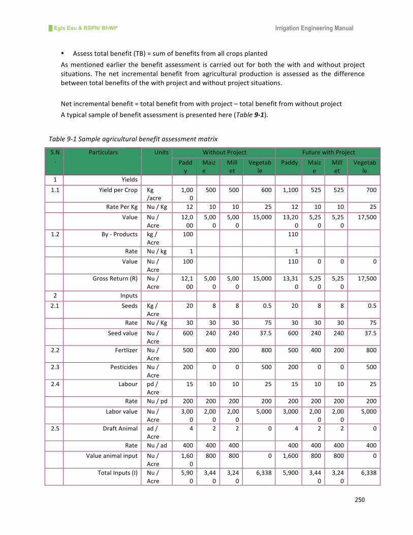
█ Egis Eau & RSPN/ BhWP Irrigation Engineering Manual
250
• Assesstotalbenefit(TB)=sumofbenefitsfromallcropsplanted
Asmentionedearlier thebenefit assessment is carriedout forboth thewith andwithoutproject
situations. The net incremental benefit from agricultural production is assessed as the difference
betweentotalbenefitsofthewithprojectandwithoutprojectsituations.
Netincrementalbenefit=totalbenefitfromwithproject–totalbenefitfromwithoutproject
Atypicalsampleofbenefitassessmentispresentedhere(Table9-1).
Table9-1Sampleagriculturalbenefitassessmentmatrix
S.N
.
Particulars Units WithoutProject FuturewithProject
Padd
y
Maiz
e
Mill
et
Vegetab
le
Paddy Maiz
e
Mill
et
Vegetab
le
1 Yields
1.1 YieldperCrop Kg
/acre
1,00
0
500 500 600 1,100 525 525 700
RatePerKg Nu/Kg 12 10 10 25 12 10 10 25
Value Nu/
Acre
12,0
00
5,00
0
5,00
0
15,000 13,20
0
5,25
0
5,25
0
17,500
1.2 By-Products kg/
Acre
100 110
Rate Nu/kg 1 1
Value Nu/
Acre
100 110 0 0 0
GrossReturn(R) Nu/
Acre
12,1
00
5,00
0
5,00
0
15,000 13,31
0
5,25
0
5,25
0
17,500
2 Inputs
2.1 Seeds Kg/
Acre
20 8 8 0.5 20 8 8 0.5
Rate Nu/Kg 30 30 30 75 30 30 30 75
Seedvalue Nu/
Acre
600 240 240 37.5 600 240 240 37.5
2.2 Fertlizer Nu/
Acre
500 400 200 800 500 400 200 800
2.3 Pesticides Nu/
Acre
200 0 0 500 200 0 0 500
2.4 Labour pd/
Acre
15 10 10 25 15 10 10 25
Rate Nu/pd 200 200 200 200 200 200 200 200
Laborvalue Nu/
Acre
3,00
0
2,00
0
2,00
0
5,000 3,000 2,00
0
2,00
0
5,000
2.5 DraftAnimal ad/
Acre
4 2 2 0 4 2 2 0
Rate Nu/ad 400 400 400 400 400 400 400
Valueanimalinput Nu/
Acre
1,60
0
800 800 0 1,600 800 800 0
TotalInputs(I) Nu/
Acre
5,90
0
3,44
0
3,24
0
6,338 5,900 3,44
0
3,24
0
6,338
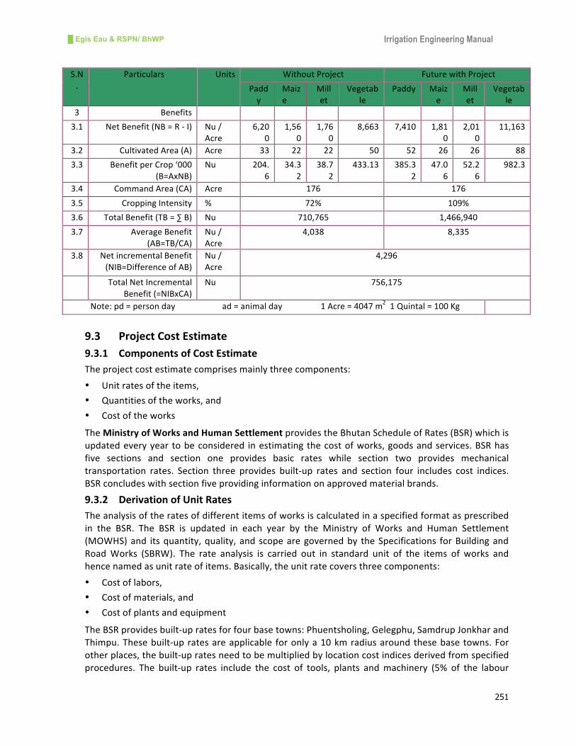
█ Egis Eau & RSPN/ BhWP Irrigation Engineering Manual
251
S.N
.
Particulars Units WithoutProject FuturewithProject
Padd
y
Maiz
e
Mill
et
Vegetab
le
Paddy Maiz
e
Mill
et
Vegetab
le
3 Benefits
3.1 NetBenefit(NB=R-I) Nu/
Acre
6,20
0
1,56
0
1,76
0
8,663 7,410 1,81
0
2,01
0
11,163
3.2 CultivatedArea(A) Acre 33 22 22 50 52 26 26 88
3.3 BenefitperCrop‘000
(B=AxNB)
Nu 204.
6
34.3
2
38.7
2
433.13 385.3
2
47.0
6
52.2
6
982.3
3.4 CommandArea(CA) Acre 176 176
3.5 CroppingIntensity % 72% 109%
3.6 TotalBenefit(TB=∑B) Nu 710,765 1,466,940
3.7 AverageBenefit
(AB=TB/CA)
Nu/
Acre
4,038 8,335
3.8 NetincrementalBenefit
(NIB=DifferenceofAB)
Nu/
Acre
4,296
TotalNetIncremental
Benefit(=NIBxCA)
Nu 756,175
Note:pd=persondayad=animalday1Acre=4047m21Quintal=100Kg
9.3 ProjectCostEstimate
9.3.1 ComponentsofCostEstimate
Theprojectcostestimatecomprisesmainlythreecomponents:
• Unitratesoftheitems,
• Quantitiesoftheworks,and
• Costoftheworks
TheMinistryofWorksandHumanSettlementprovidestheBhutanScheduleofRates(BSR)whichis
updatedeveryyear tobeconsidered inestimatingthecostofworks,goodsandservices.BSRhas
five sections and section one provides basic rates while section two provides mechanical
transportation rates. Section three provides built-up rates and section four includes cost indices.
BSRconcludeswithsectionfiveprovidinginformationonapprovedmaterialbrands.
9.3.2 DerivationofUnitRates
Theanalysisoftheratesofdifferentitemsofworksiscalculatedinaspecifiedformatasprescribed
in the BSR. The BSR is updated in each year by the Ministry of Works and Human Settlement
(MOWHS)and itsquantity,quality, and scopearegovernedby theSpecifications forBuildingand
RoadWorks (SBRW). The rate analysis is carried out in standard unit of the items of works and
hencenamedasunitrateofitems.Basically,theunitratecoversthreecomponents:
• Costoflabors,
• Costofmaterials,and
• Costofplantsandequipment
TheBSRprovidesbuilt-upratesforfourbasetowns:Phuentsholing,Gelegphu,SamdrupJonkharand
Thimpu.Thesebuilt-upratesareapplicable foronlya10kmradiusaroundthesebasetowns.For
otherplaces,thebuilt-upratesneedtobemultipliedbylocationcostindicesderivedfromspecified
procedures. The built-up rates include the cost of tools, plants andmachinery (5% of the labour

█ Egis Eau & RSPN/ BhWP Irrigation Engineering Manual
252
cost),thecostofworkcharges(1%of labourcost),andthecostofconstructionoverhead(10%of
the total rate). In addition, the built-up rates are derived from the “Labour and Material
Coefficients”ofthesameyearpublishedbyMOWHS.
Thebasic rates for thespecified locationsareobtainedbymultiplyingwithcost indiceswhichare
calculatedaccordingtothefollowingprocedures:
i. Determinebasicratesofeachitemsofworksfromnearestbasetown,
ii. Determinestheratesofeachitemsofworksoftheprojectlocation,
iii. Calculatetheincreaseinprojectratesinpercentfrombasetownrates,
1001Pr
×⎟⎟⎠
⎞⎜⎜⎝
⎛−=
ratetownBase
rateojectrateinIncrease
iv. Calculateweightageofeachitemoftheworkswhichshallremainfixed,
v. Calculateweightagecostindexofeachitemofworks,
100÷=Weightage
rateinIncreaseindexCost
vi. Calculatethetotalcostindexoftheprojectbysummingthecostindicesofeachitemsofworks,
Thecostindicesareapplicableforallbasicratesandanyotherworkswhereonlylabourisinvolved
suchasdismantlingworks,earthworks,installationandtestingworksetc.Theunitrateoftheitem
thatisnotincludedinBSRneedtobeapprovedbytheChiefEngineerofEngineeringDivision.
9.3.3 CalculationofQuantities
Thequantitiesarecalculatedaccordingtotheexactdimensionsoftheworksasmentionedonthe
projectdrawings.Thesedimensionsarefragmentedintosmallgeometricalshapeandsizeinorder
to ease the calculations. The geometrical shapesmay be rectangle, circle, triangle, parallelogram
etc.Inmostcasesthequantitiesarecalculatedmultiplyingthelength,widthandheightordepthof
theobjecttobeassessed.Inaddition,thequantitiesmaybeinvariousunitssuchasnumber,length,
area and volumebasedon thenatureof theworks. The appropriate formatof quantity estimate
with example is given here (Table 9-2). Furthermore, some of the items of work are difficult to
quantify and these items are expressed in lump sum quantity such as site preparation, site
mobilization,etc.
Table9-2Samplequantityestimateform
Item
no
Description Unit No Length Breadth Height Quantity Remarks
1 Earth work
excavation
m3 2 2.50 2.00 1.00 10.00
2 Siteclearance m2 2 2.50 2.00 - 10.00
3 Barbedwire m 2 90.00 - - 180.00
4 Railing post of
specifiedsize
no 1 - - - 1.00

█ Egis Eau & RSPN/ BhWP Irrigation Engineering Manual
253
9.3.4 EstimateofCost
Thecostof theworks isderivedfromthemultiplicationof theunit itemratewiththequantityof
eachitem.
Cost=quantityxunitrate
In addition to themain items of work of the project, the cost shall also include the cost of the
followingitemsbasedonthenatureandtypeoftheproject:
• Mobilizationanddemobilizationcost,
• Insurancecost,
• Costofconsultingservice,
• Constructionsupervisioncost,
• Costofprofessionalsecurityandsafety,
• Costforpreparingcompletiondrawing,and
• Costofbankcommissionforperformancedeposits
The preparation of the cost estimate of the project depends upon its nature, size and funding
agency.Theformatoftheestimatingthecostoftheprojectisprescribedhere(Table9-3).
Table9-3Samplecostestimateform
Item
no
Code Description
ofitems
Unit Quantity Unit
rate
Amount Remarks
(a) (b) (c) (d) (e) (f) (g) (h)
1 Item1 (e)x(f)
2 Item2 (e)x(f)
3
Totalbasiccost(i) = ∑g
Contingency@5%ofbasiccost(j) (j)=0.05x(i)
Sub-total(k) (k)=(i)+(j)
VAT@13%(l) (l)=0.13x(k)
Totalconstructioncost(m) (m)=(k)+(l)
9.4 EconomicAnalysis
9.4.1 Introduction
Economicanalysis istheprocessofevaluatingthebestfeasibleprojectsamongseveralalternative
projects. The main objective of the economic analysis is to assess the economic viability of the
project under consideration. For irrigation projects, the analysis is based on the net incremental
benefitsarisingfromtheprojectandtheeconomiccostoftheprojectfor itsassumedlifetime.To
assesstheincrementalbenefits,itisnecessarytoidentifythecostsandbenefitsthatwillarisewith
the implementation of the project and to compare themwith the costs and benefits thatwould
havearisenwithout the implementationof theproject.Mostof the irrigationprojectsare judged
█ Egis Eau & RSPN/ BhWP Irrigation Engineering Manual
254
with threeeconomic indicators,NetPresentValue (NPV),Economic InternalRateofReturn (EIRR)
andBenefit-costRation(BCR).Thefollowingsectionsbrieflydescribetheseeconomicindicators.
9.4.2 EconomicIndicators
NetPresentValue(NPV)isthesumofpresentvaluesoftheincrementalbenefits,discountedatthe
fixed rate. The project with a positive NPV is said to be economically viable and in comparing
alternatives,theprojectwiththehigherNPVwouldbechosen.
Economic Internal Rate of Return (EIRR) is the discount rate which makes the NPV of the
incrementalbenefitsequaltozero. It isthediscountrate,whichensuresthatthepresentvalueof
theprojectbenefitsisthesameasthepresentvalueofthecosts.TheEIRRoftheprojectshouldbe
more than the opportunity cost of capital or discount rate. The discount rate is usually 10% in
developingcountries.
Benefit-CostRatio(BCR)isthepresentvalueoftheprojectbenefitsdividedbythepresentvalueof
costs.IftheBCRisgreaterthanone,thentheprojectiseconomicallyviable.
Discountingistheprocessofcomparingpresentamountsofmoneywithfutureamountsofmoney.
Inaddition,discountingcalculatestheamountofmoneyrequiredtodaywhich,wheninvestedata
rateofinterestequivalenttothediscountrate,wouldyieldthefutureamount.Discountingisused
to compare the costs andbenefits of theprojectof different times at a singlepointof time. It is
usuallyat the timeofprojectappraisal. If thecapital isRs1000andthe interest rate is8%, then
totalcapitalafteroneyearwouldbeRs1080,orinoneyearRs1080isworthRs1000ifthediscount
rateis8%.
9.4.3 BasicAssumptions
Economicanalysisiscarriedoutbasedonsomebasicassumptionswhichareasfollows:
w Life of the project- depends upon the nature of structure to be constructed. For small
irrigationschemesthelifeoftheprojectmaybe10-20years,
w Construction period- the construction period of the project depends upon its size and
location.Forsmallscaleirrigationschemestheconstructionperiodmaybe1-2years,
w Build up period for full agricultural benefits- with the implementation of the irrigation
projectagriculturalbenefitswouldnotaccrueatonceandwilltake1-3years,
w OpportunitycostofcapitalordiscountrateinBhutantobetakenis10%;
w Standardconversionfactorsfortheconversionoffinancialcosttoeconomiccostsaretaken
as0.95forconstructioncostsand0.90foroperationandmaintenancecosts.
9.4.4 ProceduresofEconomicAnalysis
i. Assesstotalnetagriculturalreturnswithoutproject
§ Preparecropinputandoutputassumptions
§ Calculatefarmgatepricesofcommodity
§ Preparewithoutprojectcropbudgets
§ Calculatewithoutprojectcroppedareasinthecommandarea
§ Calculatetotalnetagriculturalreturnswithoutproject

█ Egis Eau & RSPN/ BhWP Irrigation Engineering Manual
255
Totalwithoutprojectnetagricultural returnsperannum=CommandareawithoutprojectxCropping
pattern=AreaofeachcropxNeteconomicreturnfromeachcrop
ii. Assesstotalnetagriculturalreturnswithproject
§ Preparecropbudgets
§ Calculatewithprojectcroppedareasinthecommandarea
§ Calculatetotalnetagriculturalreturnswithproject
Total with project net agricultural returns per annum = Command area with project x Cropping
pattern=AreaofeachcropxNeteconomicreturnfromeachcrop
iii. Calculatenetagriculturalbenefitsperannumatfullproduction
Netagriculturalbenefitperannum=Totalwithprojectnetagriculturalreturnsperannum(a)-Total
withoutprojectnetagriculturalreturnsperannum(b)
iv. Estimatethefinancialcostoftheproject
§ Summaryofcostofconstruction
§ Calculateoperationandmaintenancecost
§ Costofland
v. Subtractcostoflandacquisitionfromfinancialcosttheproject,
Financialconstructioncosts–Landacquisitioncost=Netfinancialconstructioncosts
vi. Convertnetfinancialconstructioncoststoeconomiccosts,
§ Allocateconstructioncostintoperiod:
§ Addtotalpresentvalueofoperationandmaintenancecosts“withproject”,
§ Addtotalpresentvalueoflandlevelingcosts“withproject”,
§ Subtracttotalpresentvalueof“withoutproject”operationandmaintenancecosts,
§ Presentvalueoftotalcosts,
Netfinancialo&mcostsxConversionfactor=Economico&mcosts
vii. Assessnetpresentvalue
Thepresentvalueofbenefitsisdividedbythepresentvalueofcoststoproducethebenefit-cost
ratio,whichistakenasthebasicmeasureofthesystem’seconomicviability.
TotalPVofbenefits/TotalPVofcosts=Benefit/costratio
viii. ComputeEconomicInternalRateofReturn(EIRR)
EIRR = %&' +%&' − *&'
(,-'/0%&' − ,-'/0*&'× 1 − ,-'/0%&'
Where,EIRRiseconomicinternalrateofreturn,
HDRishigherdiscountrate,
LDRislowerdiscountrate,
BCRisbenefitcostratio
Atypicalexampleofeconomicanalysisispresentedin.

█ Egis Eau & RSPN/ BhWP Irrigation Engineering Manual
256
Table9-4TypicalExampleofEconomicAnalysis
NameofProject:
TotalProjectCost(NRs): 850,976.16 Assumptions:
NetIncrementalBenefit(NRs): 383,019.25 Lifeofproject: 10years Coversionfactor:
O&Mcost(NRs): 25,529.28 Benefitstartsfrom2ndyear Forconstructioncost: 0.95
ForO&Mcost: 0.90
at10% at12%
10 12 at10% at12% at10% at12%
1 808,427.35 808,427.35 0.909 0.893 734,860.46 721,925.63 - -
2 22,976.36 22,976.36 191,509.63 0.826 0.797 18,978.47 18,312.16 158,186.95 152,633.17
3 22,976.36 22,976.36 383,019.25 0.751 0.712 17,255.24 16,359.17 287,647.46 272,709.71
4 22,976.36 22,976.36 383,019.25 0.683 0.636 15,692.85 14,612.96 261,602.15 243,600.24
5 22,976.36 22,976.36 383,019.25 0.621 0.567 14,268.32 13,027.59 237,854.95 217,171.91
6 22,976.36 22,976.36 383,019.25 0.564 0.507 12,958.66 11,649.01 216,022.86 194,190.76
7 22,976.36 22,976.36 383,019.25 0.513 0.452 11,786.87 10,385.31 196,488.88 173,124.70
8 22,976.36 22,976.36 383,019.25 0.467 0.404 10,729.96 9,282.45 178,869.99 154,739.78
9 22,976.36 22,976.36 383,019.25 0.424 0.361 9,741.98 8,294.46 162,400.16 138,269.95
10 22,976.36 22,976.36 383,019.25 0.386 0.322 8,868.87 7,398.39 147,845.43 123,332.20
808,427.35 206,787.21 1,015,214.56 3,255,663.63 855,141.69 831,247.13 1,846,918.82 1,669,772.42
B/CRatioat10% 2.16
B/CRatioat12% 2.01
EIRR % 23.36
EconomicAnalysis
Year Construction
cost(NRs)
O&Mcost
(NRs)
Totalcost
(NRs)
Benefit(NRs) Discountfactors Presentvalue(NRs)
Cost Benefit

█ Egis Eau & RSPN/ BhWP Irrigation Engineering Manual
257
10. BasisTermsUsedintheManual
Afflux : the rise of water level on the u/s of the weir or barrage after its construction,
Alignment : center line of the canal to be followed for excavation or profiling,
Apron : floor protecting the surface from erosion,
Aqueduct : cross drainage structure made over a drainage to carry the canal water,
Barrage : structure across the river with gates which raises the water level in the irrigation canals,
Basin : pool of water - stilling basin, desilting basin, etc.
Bench mark : geodetic reference point taken from a national survey of the country,
Breast wall : vertical wall immediately above the face of the orifice or gate,
Cascade : structure which conveys water over a series of drops,
Catchment area: area from which rainfall flows into a drainage line,
Chute : high velocity conduit for conveying water at the sloping profile,
Command area : area which can be irrigated or cultivated,
Crop coefficient: ratio of reference crop evapotranspiration to crop evapotranspiration,
Cropping intensity: percentage of irrigated area cropped within the irrigation command area,
Cropping pattern: crop planting sequence and crop mix throughout a year,
Cross drainage works: structure needed to carry irrigation canal water across the drainage channel,
Culturalcommandarea(CCA): totalareawhichcanbecultivated,
Culvert : structure allowing water to flow,
Cut-off : wall constructed below the floor of the structure to reduce percolation,
Desilting basin : structure which creates a pool of water to allow suspended sediments to settle,
Drop : structure for dropping the flow of the canal to dissipate its surplus energy,
Embankment : earthwork raised above the natural ground to protect against flood water,
Escape : structure required to enable excess water to escape from the canal,
Flood control : provision to minimize or reduce flood magnitude,
Free board : margin between a canal bank and the full supply level,
Gross command area (GCA): total area which can be economically irrigated by an irrigation system,
Guide bank : training bank constructed at the site of a bridge or barrage to guide the river,
Head regulator : control structure constructed at the head of the off-take canal,
Headwork : combination of structures constructed at the diversion point of the river,
Hydrograph : graph showing the stage, flow of water with respect to time,
Intake : structure to divert water from the source to the canal system,
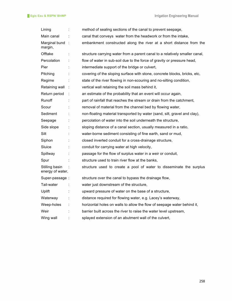
█ Egis Eau & RSPN/ BhWP Irrigation Engineering Manual
258
Lining : method of sealing sections of the canal to prevent seepage,
Main canal : canal that conveys water from the headwork or from the intake,
Marginal bund : embankment constructed along the river at a short distance from the margin,
Offtake : structure carrying water from a parent canal to a relatively smaller canal,
Percolation : flow of water in sub-soil due to the force of gravity or pressure head,
Pier : intermediate support of the bridge or culvert,
Pitching : covering of the sloping surface with stone, concrete blocks, bricks, etc,
Regime : state of the river flowing in non-scouring and no-silting condition,
Retaining wall : vertical wall retaining the soil mass behind it,
Return period : an estimate of the probability that an event will occur again,
Runoff : part of rainfall that reaches the stream or drain from the catchment,
Scour : removal of material from the channel bed by flowing water,
Sediment : non-floating material transported by water (sand, silt, gravel and clay),
Seepage : percolation of water into the soil underneath the structure,
Side slope : sloping distance of a canal section, usually measured in a ratio,
Silt : water-borne sediment consisting of fine earth, sand or mud,
Siphon : closed inverted conduit for a cross-drainage structure,
Sluice : conduit for carrying water at high velocity,
Spillway : passage for the flow of surplus water in a weir or conduit,
Spur : structure used to train river flow at the banks,
Stilling basin : structure used to create a pool of water to disseminate the surplus energy of water,
Super-passage : structure over the canal to bypass the drainage flow,
Tail-water : water just downstream of the structure,
Uplift : upward pressure of water on the base of a structure,
Waterway : distance required for flowing water, e.g. Lacey’s waterway,
Weep-holes : horizontal holes on walls to allow the flow of seepage water behind it,
Weir : barrier built across the river to raise the water level upstream,
Wing wall : splayed extension of an abutment wall of the culvert,

█ Egis Eau & RSPN/ BhWP Irrigation Engineering Manual
259
11. References
1. ADB/ICEM,ClimateChangeVulnerabilityAssessmentandAdaptationPlanningMethodology
for Infrastructure Development in Nepal (Draft), Asian Development Bank/International
CenterforEnvironmentManagement/GovernmentofNepal,Kathmandu,2014,
2. AHEC/MNRE, Standards/Manuals/Guidelines for SmallHydroDevelopment, Version-2 Civil
Works-HydraulicDesignofSmallHydroPlants,GovernmentofIndia,MinistryofNewand
RenewableEnergy,AlternateHydroEnergyCenter/IndianInstituteofTechnologyRoorkee,
India,2011,
3. Ahmed Z. andMittalM. K., Recent Advances in the Design of TrenchWeir, Unpublished
Paper,IndianInstituteofTechnology,Roorkee,India,
4. Alberta Transportation,Water control structures- Selected Design Guidelines, November,
2004,
5. AndreasP. S. andKarenF., CropWaterRequirementsand IrrigationScheduling, Irrigation
ManualModule4,FoodandAgricultureOrganization,Harare,Zambia,2002,
6. AndreasP.S.andKarenF.,IrrigationPumpingPlants,IrrigationManualModule5,Foodand
AgricultureOrganization,Harare,2001,
7. BasakN.K., IrrigationEngineering,TataMcGrawHillEducationPrivateLimited,NewDelhi,
India,1999
8. Basil Jacob S., Hill Irrigation Engineering with Special Emphasis on Planning, Design and
ImplementationofFarmerHillSystems,IOE/FordFoundation,Kathmandu,Nepal,1995
9. BIS, IndianStandards:HydraulicDesignofBarragesandWeirs–Guidelines, FirstRevision,
BureauofIndianStandards,NewDelhi,India,1989,
10. BIS, Indian Standards: Laying Cement Concrete/Stone Slab Lining on Canals – Code of
Practice,SecondRevision,BureauofIndianStandards,NewDelhi,India,1993,
11. BIS, Indian Standards: Soil-Cement Lining for Canals – Code of Practice, First Revision,
BureauofIndianStandards,NewDelhi,India,2003,
12. ChowV.T.,HandbookofAppliedHydrology,McGrawHill,1964,
13. ChowV.T.,OpenChannelFlow,McGrawHill,Tokyo,1959,
14. D.B.KraatzandI.K.Mahajan,SmallHydraulicStructures,IrrigationandDrainagePaperNo
26/1and2,Rome,Italy,1976
15. DFID, Smallholders Irrigation: Ways Forward, Guidelines for Minor Irrigation Design,
Wallingford/DepartmentforInternationalDevelopment,UK,1997,
16. DOA, National Irrigation Information System, Department of Agriculture, Ministry of
AgricultureandForest,2012,
17. FAO, Climate-Smart Agriculture, Sourcebook, Food and Agriculture Organization, Rome,
Italy,2013,
18. FAO, FAO’s Framework Program on Climate Change Adaptation, Food and Agriculture
Organization,Rome,Italy,2011,

█ Egis Eau & RSPN/ BhWP Irrigation Engineering Manual
260
19. FAO,GuidelinesforPredictingCropWaterRequirements,IrrigationandDrainagePaper24,
FAO,Rome,Italy,1977,
20. FAO, Irrigation Management Training Manual No 7: Canals, Food and Agriculture
Organization,Rome,Italy,1992,
21. FrancoisB.andMartenB., LinkingTechnologyChoicewithOperationandMaintenance in
thecontextofCommunityWaterSupplyandSanitation,AReferenceDocumentforPlanners
andProjectStaff,WorldHealthOrganizationandIRCWaterandSanitationCenter,Geneva,
Switzerland,2003;
22. GabrielM. N. Kalinga and Guna N. Paudyal, A study On The Bottom Intake Structure for
StreamflowAbstraction,AITResearchReportNo.232,Bangkok,1989,
23. GOI/CWC,Manual on Irrigation and Power Channels, Publication no 17, Central Board of
IrrigationandPower,NewDelhi,India,1984,
24. GON/DOI,DesignManualsforIrrigationProjectsinNepal,ProjectDesignandStrengthening
Project,DepartmentofIrrigation,Nepal,1990
25. Halcrow-BCEOM-DHV,DraftDesignManual forSystemsRehabilitationProject,Bangladesh
Water Development Board,Ministry of IrrigationWater Development and Flood Control,
Dhaka,Bangladesh,1992,
26. HelmutL.andGangolfS.,PlanningofWaterIntakeStructuresforIrrigationorHydropower,
APublicationofGTZ-PostharvestProject,GmbH,Eschborn,Germany,1989
27. Helmut Lauterjung and Gangolf Schmidt - Planning of Intake Structure, A Publication of
GATE/GTZ
28. HervePlusquellec,CharlesBurt,andHansW.Wolter,ModernWaterControl inIrrigation -
Concepts,Issues,andApplications,TechnicalPaperNo.246,IrrigationandDrainageSeries,
theWorldBank,1994,
29. Horst L., The Dilemmas ofWater Division, Consideration and Criteria for IrrigationSystem
Design, International Water Management Institute/Wageningen Agricultural University,
Colombo,ShriLanka,1998,
30. HRWallingford/ODA,AProcedureforPlanningIrrigationSchemeRehabilitation,TDRProject
R5832 Report OD/TN 84, HR Wallingford/Overseas Development Administration of the
UnitedKingdom,1997,
31. IDE, Technical Manual for IDEal Micro Irrigation Systems, International Development
EnterpriseandCGIARChallengeProgramonWaterandFood,2000,
32. ILO/GON,AppropriateDesignofSmall-scaleHill IrrigationStructures,SPWPManualNo2,
UNDP/ILO/GON,Kathmandu,Nepal,1990,
33. ISI, Indian Standard: Criteria forHydraulicDesignof Irrigation Intake Structures, IS:11570-
1985,IndianStandardsInstitution,NewDelhi,India,1986,
34. ISI, Indian Standards: Plain and Reinforced Concrete – Code of Practice, Fourth Revision,
IndianStandardsInstitution,NewDelhi,India,2007,
35. NEC, Bhutan Water Vision and Water Policy, National Environment Commission, Royal
GovernmentofBhutan,2003,
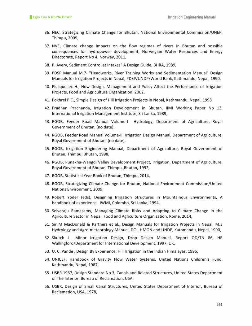
█ Egis Eau & RSPN/ BhWP Irrigation Engineering Manual
261
36. NEC, Strategizing Climate Change for Bhutan, National Environmental Commission/UNEP,
Thimpu,2009,
37. NVE, Climate change impacts on the flow regimes of rivers in Bhutan and possible
consequences for hydropower development, Norwegian Water Resources and Energy
Directorate,ReportNo4,Norway,2011,
38. P.Avery,SedimentControlatIntakes"ADesignGuide,BHRA,1989,
39. PDSPManualM.7- "Headworks, River TrainingWorks and SedimentationManual" Design
ManualsforIrrigationProjectsinNepal,PDSP/UNDP/WorldBank,Kathmandu,Nepal,1990,
40. Plusquellec H., HowDesign,Management and Policy Affect the Performance of Irrigation
Projects,FoodandAgricultureOrganization,2002,
41. PokhrelP.C.,SimpleDesignofHillIrrigationProjectsinNepal,Kathmandu,Nepal,1998
42. Pradhan Prachanda, Irrigation Development in Bhutan, IIMI Working Paper No 13,
InternationalIrrigationManagementInstitute,SriLanka,1989,
43. RGOB, Feeder Road Manual Volume-I Hydrology, Department of Agriculture, Royal
GovernmentofBhutan,(nodate),
44. RGOB,FeederRoadManualVolume-IIIrrigationDesignManual,DepartmentofAgriculture,
RoyalGovernmentofBhutan,(nodate),
45. RGOB, Irrigation Engineering Manual, Department of Agriculture, Royal Government of
Bhutan,Thimpu,Bhutan,1998,
46. RGOB,Punakha-WangdiValleyDevelopmentProject, Irrigation,DepartmentofAgriculture,
RoyalGovernmentofBhutan,Thimpu,Bhutan,1992,
47. RGOB,StatisticalYearBookofBhutan,Thimpu,2014,
48. RGOB, Strategizing Climate Change for Bhutan, National Environment Commission/United
NationsEnvironment,2009,
49. Robert Yoder (eds), Designing Irrigation Structures in Mountainous Environments, A
handbookofexperience,IWMI,Colombo,SriLanka,1994,
50. Selvaraju Ramasamy, Managing Climate Risks and Adapting to Climate Change in the
AgricultureSectorinNepal,FoodandAgricultureOrganization,Rome,2014,
51. Sir MMacDonald & Partners et al., DesignManuals for Irrigation Projects in Nepal, M.3
HydrologyandAgro-meteorologyManual,DOI,HMGNandUNDP,Kathmandu,Nepal,1990,
52. Skutch J., Minor Irrigation Design, Drop Design Manual, Report OD/TN 86, HR
Wallingford/DepartmentforInternationalDevelopment,1997,UK,
53. U.C.Pande,DesignByExperience,HillIrrigationintheIndianHimalayas,1995,
54. UNICEF, Handbook of Gravity Flow Water Systems, United Nations Children’s Fund,
Kathmandu,Nepal,1987,
55. USBR1967,DesignStandardNo3,CanalsandRelatedStructures,UnitedStatesDepartment
ofTheInterior,BureauofReclamation,USA,
56. USBR, Design of Small Canal Structures, United States Department of Interior, Bureau of
Reclamation,USA,1978,

█ Egis Eau & RSPN/ BhWP Irrigation Engineering Manual
262
57. VarshneyR.S,GuptaS.C.andGuptaR.L.,TheoryandPracticeof IrrigationStructures,Nem
Chand,Roorkee,India,1977
58. WECS and DHM, Methodologies for Estimating Hydrologic Characteristics of Ungauged
LocationsinNepal,WaterandEnergyCommissionSecretariatandDepartmentofHydrology
andMeteorology,Kathmandu,Nepal,1990,