Adapted control systems for house service connection stations of huge performance – domestic hot...
16
Adapted control systems for house service connection stations of huge performance – domestic hot water supply based on continuous flow system Faculty of Mechanical Engineering Institute of Power Engineering, Second Euroheat & Power RTD Workshop Brussels, 2-3 February 2006 Dipl.-Ing. Norbert Wünsche, Dr.-Ing. Karin Rühling TU Dresden, Institut of Power Engineering This presentation is based on a research project financially supported by the German Federal Ministry of Economy within the PROgramm “INNOvationskompetenz mittelständischer Unternehmen” (KF 0100804KMH3) Professorship of Energy System Engineering and Heat Economy
-
Upload
blake-hunter -
Category
Documents
-
view
212 -
download
0
Transcript of Adapted control systems for house service connection stations of huge performance – domestic hot...

Adapted control systems for house service connection stations of huge performance – domestic hot water supply based on continuous flow system
Faculty of Mechanical Engineering Institute of Power Engineering,
Second Euroheat & Power RTD WorkshopBrussels, 2-3 February 2006
Dipl.-Ing. Norbert Wünsche, Dr.-Ing. Karin Rühling TU Dresden, Institut of Power Engineering
This presentation is based on a research project financially supported by the German Federal Ministry of Economy within the PROgramm “INNOvationskompetenz mittelständischer Unternehmen” (KF 0100804KMH3)
Professorship of Energy System Engineering and Heat Economy

Brussels, 2 February 2006 Huge DHW supply based on continuous flow systemWünsche/Rühling
Slide 2
MOTIVATION
Domestic hot water supply in the range of 100 kW to 1 MW
Standard installations temporary mostly as storage systems favourable conditions for growth of Legionella
Cause of high quality standards (TrinkwV, DVGW W 551) special solutions with considerable high efforts necessary
Sto
rage c
harg
ing s
yst
em
Sto
rage o
f D
HW
Sto
rage s
yst
em
Sto
rage o
f D
HW
T
M
T
DHW
DW
supply
returnM
T
DHW
DW
supply
return
T
DHW
DW
supply
return
T
DHW
DWM
T
supply
return M
a b
c d
storage system - storage of DHW storage charging system - storage of DHW
Continuous flow system - without storage Continuous flow system with primary storage - storage of heating water

Brussels, 2 February 2006 Huge DHW supply based on continuous flow systemWünsche/Rühling
Slide 3
OBJEKTIVE
Check, if continuous flow system can be applied simple hydraulic circuit
primary storage for heating water
domestic hot water temperature control system based on speed control of electronic pumps
Conti
nuous
flow
syst
em
w
ith p
rim
ary
sto
rage
Sto
rage o
f heati
ng w
ate
r
Conti
nuous
flow
sy
stem
Wit
hout
stora
ge
T
M
T
DHW
DW
supply
returnM
T
DHW
DW
supply
return
T
DHW
DW
supply
return
T
DHW
DWM
T
supply
return M
a b
c d
storage system - storage of DHW storage charging system - storage of DHW
Continuous flow system - without storage Continuous flow system with primary storage - storage of heating water

Brussels, 2 February 2006 Huge DHW supply based on continuous flow systemWünsche/Rühling
Slide 4
Tested basic configurations on DHW side
Two-stage principle – during tapping treturn , as no mixing circulation/cold DW
primary storage
of heating water
supply
return
DHW
DW
circulation
Brussels, 2 February 2006 Huge DHW supply based on continuous flow systemWünsche/Rühling
Slide 5
Basic configurations for charging the primary storage
Contr
ol sy
stem
wit
hout
auxili
ary
pow
er
dem
and
Therm
o m
ech
an
ical valv
e
Thre
e-p
oin
t co
ntr
ol
Moto
r co
ntr
ol valv
e
dir
ect
charg
ing
Tw
o-p
oin
t co
ntr
ol
Moto
r co
ntr
ol valv
e
Thre
e-p
oin
t co
ntr
ol
Moto
r co
ntr
ol valv
e
indir
ect
charg
ing
Adjusted charging temperature
Brussels, 2 February 2006 Huge DHW supply based on continuous flow systemWünsche/Rühling
Slide 6
Choice of the pump
0
1
2
3
4
5
6
7
8
9
10
0 1 2 3 4 5 6 7 8
flow rate in m³/h
pres
sure
hea
d in
m H
2O
100%
90%
80%
70%
60%
50%
25%12%
design point 250 kW
200 kW
150 kW
Limit of control range

Brussels, 2 February 2006 Huge DHW supply based on continuous flow systemWünsche/Rühling
Slide 7
Set-up of the laboratory test facility
SIKA-Strömungskontrollschalter Temp.KW
Temp.RL Zirk
Temp. WÜEintritt
Temp. WÜAustritt
Temp. TWWmitFühlerkopf-transmitter
Rückschlagklappe
temp. HX inlet
temp. DHW with sensor head trans-mitter
temp. circ. return
SIKA flow control switch temp. DW nonreturn valve
temp. HX outlet
Single-stage realisation
Qth, design = f(tstorage)
= 100 …150 kW
Switching the mixing valve via flow control switch
0 .. 12 l/min tHX,in=65 °C
> 12 l/min tHX,in= tstorage
Control pump Grundfos TPE 25-90R (smallest available)
Plate HX SWEP B28 x 30
Rudert DW-storage 200 l
Brussels, 2 February 2006 Huge DHW supply based on continuous flow systemWünsche/Rühling
Slide 8
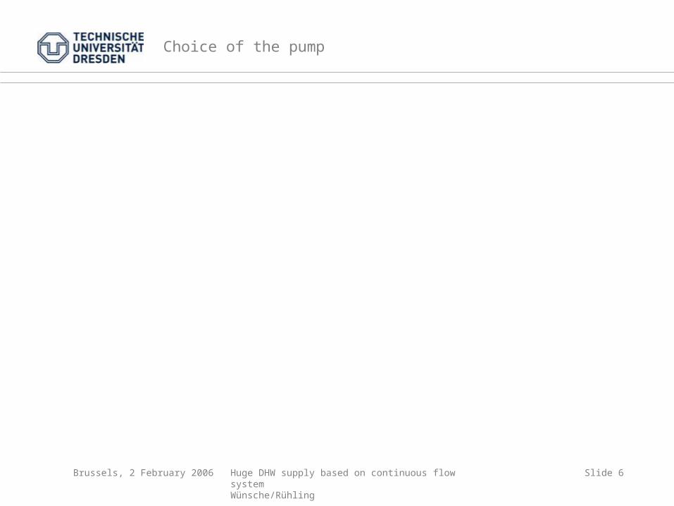
Key aspects of the laboratory tests
Test of different hydraulic circuits
Measuring the time constants of different temperature sensors
Placement of DW-temperature sensor in heat exchanger
Examination of the control range of the electronic pump
Dimensioning the admix-quantity
Choice of proper mixing valve
Choice of appropriate flow control switch
Optimisation of pump control parameters

Brussels, 2 February 2006 Huge DHW supply based on continuous flow systemWünsche/Rühling
Slide 9
Selected results of the laboratory tests with 72 °C storage temperature
40
45
50
55
60
65
70
0 2 4 6 8 10 12 14 16 18 20 22 24 26 28 30 32 34 36 min
Te
mp
era
tur
in °
C
0,0
0,5
1,0
1,5
2,0
2,5
3,0
Vo
lum
en
str
om
in
m³/
h .
+3K
-3K
Umschaltpunkt: SIKAHigh: 99% / Low: 75%Pumpe: kp=4,0 / Tn=10sMax: +2,2K Min: -3,6KMittleres DJ:+0,3/-1,2K
PD
16
09
02
.XL
S
VolumenstromKaltwasser
Temperatur Trinkwarmwasser
40
45
50
55
60
65
70
0 2 4 6 8 10 12 14 16 18 20 22 24 26 28 30 32 34 36 38 min
Te
mp
era
tur
in °
C
0,0
0,5
1,0
1,5
2,0
2,5
3,0
Vo
lum
en
str
om
in
m³/
h .
+3K
-3K
Umschaltpunkt: SIKAHigh: 99% / Low: 75%Pumpe: kp=4,0 / Tn=10sMax: +5,5K Min: -6,3KMittleres DJ:+0,7/-1,1K
PD
160903.X
LS
Temperatur Trinkwarmwasser
VolumenstromKaltwasser
Load profile
Step curve
Load profile
Jump function

Brussels, 2 February 2006 Huge DHW supply based on continuous flow systemWünsche/Rühling
Slide 10
Selected results of the laboratory tests
Load function /storage temperature
Maximum values
Minimum values
average positivedeviation
average negativedeviation
Step curve 72 °C +2,2 K -3,6 K +0,3 K -1,2 K
Jump function 72 °C +5,5 K -3,6 K +0,7 K -1,1 K
Step curve 80 °C +2,1 K -1,9 K +0,2 K -0,4 K
Jump function 80 °C +6,5 K -5,7 K +0,5 K -0,7 K

Brussels, 2 February 2006 Huge DHW supply based on continuous flow systemWünsche/Rühling
Slide 11
Field test – Objectives
Prove under praxis conditions
uninterrupted service,
dimensioning of performance,
stability of control,
effectiveness of primary storage (coverage of peak demands)
as well as
low return flow temperatures and thus
function of complete system
Single-stage realisation
Brussels, 2 February 2006 Huge DHW supply based on continuous flow systemWünsche/Rühling
Slide 12
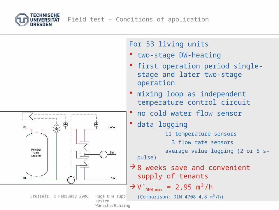
Field test – Conditions of application
For 53 living units two-stage DW-heating first operation period single-stage and
later two-stage operation mixing loop as independent
temperature control circuit no cold water flow sensor data logging
11 temperature sensors
3 flow rate sensors
average value logging (2 or 5 s–pulse)
8 weeks save and convenient supply of tenants
V´DHW,max = 2,95 m³/h (Comparison: DIN 4708 4,8 m³/h)

Brussels, 2 February 2006 Huge DHW supply based on continuous flow systemWünsche/Rühling
Slide 13
Field test - Selected results – Daily average values
Remarkable higher control stability in the two-stage realisation (± 2K)
50
52
54
56
58
60
62
64
66
68
20.02.05 27.02.05 06.03.05 13.03.05 20.03.05 27.03.05 03.04.05 10.04.05 17.04.05 24.04.05
tem
per
atu
re in
°C
single-stage two-stage
Sum
men
date
i Ber
lin.X
LS
daily average value temperature DHW
daily maximum value temperature DHW
daily minimum value temperature DHW

Brussels, 2 February 2006 Huge DHW supply based on continuous flow systemWünsche/Rühling
Slide 14
Field test - Selected results – Daily course; two-stage
0
5
10
15
20
25
30
35
40
45
50
55
60
65
0:00
1:00
2:00
3:00
4:00
5:00
6:00
7:00
8:00
9:00
10:0
0
11:0
0
12:0
0
13:0
0
14:0
0
15:0
0
16:0
0
17:0
0
18:0
0
19:0
0
20:0
0
21:0
0
22:0
0
23:0
0
0:00
time
tem
per
atu
re in
°C
0,00
0,25
0,50
0,75
1,00
1,25
1,50
1,75
2,00
2,25
2,50
2,75
3,00
3,25
flo
w r
ate
in m
³/h
Monday, 11 april 2005
temperature DHW
flow rate DHW

Brussels, 2 February 2006 Huge DHW supply based on continuous flow systemWünsche/Rühling
Slide 15
Field test - Selected results – Peak demand; two-stage
10
15
20
25
30
35
40
45
50
55
60
65
70
75
6:30
6:35
6:40
6:45
6:50
6:55
7:00
7:05
7:10
7:15
7:20
7:25
7:30 time
tem
per
atu
re in
°C
0,0
0,5
1,0
1,5
2,0
2,5
3,0
3,5
4,0
4,5
5,0
5,5
6,0
6,5
flo
w r
ate
in m
³/h
Monday, 11 april 2005
temperature DHW
flow rate DHW
flow rate primary pump

Brussels, 2 February 2006 Huge DHW supply based on continuous flow systemWünsche/Rühling
Slide 16
Field test - Selected results – Frequency distribution DHW demand
0,0
0,5
1,0
1,5
2,0
2,5
3,0
0 10 20 30 40 50 60 70 80 90 100Zeit in %
Vo
lum
enst
rom
in
m³/
h .
Verteilungsfunktion: WarmwasservolumenstromTestobjekt: Berlin Ziethenstraße 17Zeitbereich: 25.02 bis 21.04.2005max. Volumenstrom : 2,948 m³/h
Auswertung Berlin 1.XLS
Volumenstrom eines flächengleichen Rechtecks: 0,134 m³/h
Verteilungsfunktion
DHW-demand only 32 % of the time only during 10 % of the time demand > 0,5 m³/h dimensioning of primary storage = f (circulation demand, operation
parameter of heat exchanger, mixing loop, storage temperature ..)
program for dimensioning
frequency distribution
flow rate of area-equivalent rectangle: 0,134 m3/h
time in %
flow
rate
in
m3/h