Adafruit Gemma M0 - mouser.com · The Gemma M0 is a super small microcontroller board, with just...
78
Adafruit Gemma M0 Created by lady ada Last updated on 2017-08-23 10:08:13 PM UTC
-
Upload
vuongkhanh -
Category
Documents
-
view
216 -
download
0
Transcript of Adafruit Gemma M0 - mouser.com · The Gemma M0 is a super small microcontroller board, with just...

Adafruit Gemma M0Created by lady ada
Last updated on 2017-08-23 10:08:13 PM UTC

258
101010111111
111314151516161818
1919202020
202121212122
23252727
Guide Contents
Guide ContentsOverviewGuided TourPinoutsJST Battery InputPower PadsInput/Output Pads
Common to all padsUnique pad capabilities
Secret SWD and Reset PadsWindows Driver InstallationManual Driver InstallationCircuitPythonReinstalling and Updating CircuitPythonFlashingFlashing UF2Flashing with BOSSAC
After flashing
CircuitPython Blinkycode.pyStatus LEDDebuggingLibraries
More infoSerial Console (REPL)Windows
Serial Drivers (for Windows 7)Determine Your Serial PortInstall Serial Port Terminal Software
Mac OSX and LinuxUsing the REPLInstalling Libraries
Installing the bundle
© Adafruit Industries https://learn.adafruit.com/adafruit-gemma-m0 Page 2 of 78

30313131313232
33
35353535
37373737
394040414242
434548515252
5454545556
5858595961
Out of space!Delete something!Use tabsMac OSX loves to add extra files.Prevent & Remove Mac OSX Hidden FilesCopy Files on Mac OSX Without Creating Hidden FilesOther Mac OSX Tips
Continuing after copy
CircuitPython Analog InCreating analog inputsGetVoltage HelperMain Loop
CircuitPython Analog OutCreating an analog outputSetting the analog outputMain Loop
CircuitPython Cap TouchCreating an capacitive touch inputMain Loop
Copper Foil Tape with Conductive Adhesive - 6mm x 15 meter rollCopper Foil Tape with Conductive Adhesive - 25mm x 15 meter rollSmall Alligator Clip Test Lead (set of 12)
CircuitPython Touch-DotStarCircuitPython UART SerialCircuitPython I2C ScanCircuitPython I2C Sensor
Small Alligator Clip to Male Jumper Wire Bundle - 12 PiecesAdafruit Si7021 Temperature & Humidity Sensor Breakout Board
Handy TipsCheck Heap Memory UsageRandom NumbersArduino IDE Setup
https://adafruit.github.io/arduino-board-index/package_adafruit_index.json
Using with Arduino IDEInstall SAMD SupportInstall Adafruit SAMDInstall Drivers (Windows 7 Only)Blink
© Adafruit Industries https://learn.adafruit.com/adafruit-gemma-m0 Page 3 of 78

6262636364646464656666666667676768687071717273
747475777777
Sucessful UploadCompilation IssuesManually bootloadingUbuntu & Linux Issue FixAdapting Sketches to M0Analog ReferencesPin Outputs & PullupsSerial vs SerialUSBAnalogWrite / PWM on Feather/Metro M0analogWrite() PWM rangeMissing header filesBootloader LaunchingAligned Memory AccessFloating Point ConversionHow Much RAM Available?Storing data in FLASHUF2 Bootloader DetailsEntering Bootloader ModeUsing the Mass Storage BootloaderUsing the BOSSA Bootloader
Windows 7 DriversVerifying Serial Port in Device ManagerRunning bossac on the command line
Updating the bootloaderGetting Rid of Windows Pop-upsMaking your own UF2DownloadsFiles:Schematic & Fabrication Print
© Adafruit Industries https://learn.adafruit.com/adafruit-gemma-m0 Page 4 of 78

Overview
The Gemma M0 is a super small microcontroller board, with just enough to build many simple projects. It may looksmall and cute: round, about the size of a quarter, with friendly alligator-clip sew pads. But do not be fooled! TheGemma M0 is incredibly powerful! We've taken the same form factor we used for the original ATtiny85-basedGemma (http://adafru.it/duB) and gave it a power up. The Gemma M0 has swapped out the lightweight ATtiny85 fora ATSAMD21E18 powerhouse.
It will super-charge your wearables! It's just as small, and it's easier to use, so you can do more.
The most exciting part of the Gemma M0 is that while you can use it with the Arduino IDE, we are shipping it withCircuitPython on board. When you plug it in, it will show up as a very small disk drive with main.py on it. Editmain.py with your favorite text editor to build your project using Python, the most popular programming language.No installs, IDE or compiler needed, so you can use it on any computer, even ChromeBooks or computers you can'tinstall software on. When you're done, unplug the Gemma M0 and your code will go with you.
© Adafruit Industries https://learn.adafruit.com/adafruit-gemma-m0 Page 5 of 78
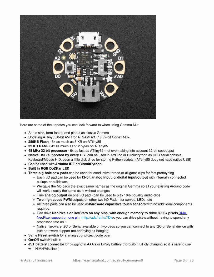
Here are some of the updates you can look forward to when using Gemma M0:
Same size, form-factor, and pinout as classic GemmaUpdating ATtiny85 8-bit AVR for ATSAMD21E18 32-bit Cortex M0+256KB Flash - 8x as much as 8 KB on ATtiny8532 KB RAM - 64x as much as 512 bytes on ATtiny8548 MHz 32 bit processor - 6x as fast as ATtiny85 (not even taking into account 32-bit speedups)Native USB supported by every OS - can be used in Arduino or CircuitPython as USB serial console,Keyboard/Mouse HID, even a little disk drive for storing Python scripts. (ATtiny85 does not have native USB)Can be used with Arduino IDE or CircuitPythonBuilt in RGB DotStar LEDThree big-hole sew-pads can be used for conductive thread or alligator-clips for fast prototyping
Each I/O pad can be used for 12-bit analog input, or digital input/output with internally connectedpullups or pulldownsWe gave the M0 pads the exact same names as the original Gemma so all your existing Arduino codewill work exactly the same as-is without changesTrue analog output on one I/O pad - can be used to play 10-bit quality audio clipsTwo high speed PWM outputs on other two I/O Pads - for servos, LEDs, etcAll three pads can also be used as hardware capacitive touch sensors with no additional componentsrequiredCan drive NeoPixels or DotStars on any pins, with enough memory to drive 8000+ pixels. DMA-NeoPixel support on one pin (http://adafru.it/xYD)so you can drive pixels without having to spend anyprocessor time on it.Native hardware I2C or Serial available on two pads so you can connect to any I2C or Serial device withtrue hardware support (no annoying bit-banging)
Same Reset switch for starting your project code overOn/Off switch built inJST battery connector for plugging in AAA's or LiPoly battery (no built-in LiPoly charging so it is safe to usewith NiMH/Alkalines)
© Adafruit Industries https://learn.adafruit.com/adafruit-gemma-m0 Page 6 of 78

Each order comes with one fully assembled and tested Gemma M0 with CircuitPython & example codeprogrammed in.
So what are you waiting for? Pick up a Gemma M0 today and be amazed at how easy and fast it is to get startedwith Gemma and CircuitPython!
© Adafruit Industries https://learn.adafruit.com/adafruit-gemma-m0 Page 7 of 78

Guided Tour
Let me take you on a tour of your Gemma M0! Each Gemma M0 is assembled here at Adafruit and comes chock-full of good design to make it a joy to use.
Micro B USB connector - We went with the tried and true micro-B USB connector for power and/or USBcommunication (bootloader, serial, HID, etc). Use with any computer with a standard data/sync cable.RGB DotStar LED - Instead of an always-on green LED we provide a full RGB LED. You can set it to anycolor in the rainbow. It will also help you know when the bootloader is running (it will turn green) or if it failed toinitialize USB when connected to a computer (it will turn green). By default after you boot up the Gemma M0 itwill turn a lovely violet color.Red #13 LED - this LED does double duty. Its connected with a series resistor to the digital #13 GPIO pin. Itpulses nicely when the Gemma is in bootloader mode, and its also handy for when you want an indicator LED.JST Battery Input - take your Gemma anywhere and power it from an external battery. This pin can take up6V DC input, and has reverse-polarity, over-curent and thermal protections. The circuitry inside will use eitherthe battery or USB power, safely switching from one to the other. If both are connected, it will use whicheverhas the higher voltage. Works great with a Lithium Polymer battery or our 3xAAA battery packs with a JSTconnector on the end. There is no built in battery charging (so that you can use Alkaline or Lithium batteriessafely)Vout (Voltage Output) - This pin will give you either the battery power or USB power, whichever has a highervoltage. Its great when you want to power something like NeoPixels, that might use more than the 500mAavailable from the onboard regulator3V Regulator - The on-board voltage regulator can supply up to 500mA at a steady 3.3V from up to 6VDCSewing and Alligator clip friendly pads - You can easily sew to these pads, and they're gold plated so theywont corrode (oxidize). You can also use alligator clips or solder directly to them.3 General Purpose I/O (GPIO) Pads! - 3 GPIO pins, at 3V logic, check the next section for a detailed pinout
© Adafruit Industries https://learn.adafruit.com/adafruit-gemma-m0 Page 8 of 78

guideReset Button - an onboard reset button will launch the bootloader when pressed and the Gemma is pluggedinto a computer. If it is not connected to a computer, it's smart enough to go straight to the program.On/Off switch - Lets you turn on/off your project, it will control both the Gemma and the Vout pad. This switchcan switch up to about 500mA of current, so if you are driving a huge number of servos or NeoPixels, connectpower to those power-greedy parts externally.
© Adafruit Industries https://learn.adafruit.com/adafruit-gemma-m0 Page 9 of 78

Pinouts
JST Battery InputThere is no battery INPUT pin on the Gemma. You can connect a battery via the JST jack. We have found thatLipoly batteries (http://adafru.it/cFB), coin-cells (http://adafru.it/783), and AAA's (http://adafru.it/727) work great. Youcan also make your own battery input pack using a plain JST cable (http://adafru.it/261). And use a JST extensioncable if necessary (http://adafru.it/1131).
You can plug anything from around 4 VDC up to 6 VDC. That means any single-cell LiPoly, or 3-4 AAA or AAbatteries. This input is polarity protected. Gemma and DotStar LED light up, you're good to go. You can turn off thebattery with the on/off switch, which will completely disconnect power on the Gemma M0.
Power PadsHalf of the pads on the Gemma M0 are related to power in and out: 3Vo , Vout and GND
Vout - This is a voltage OUTPUT pin, it will be connected to either the USB power or the battery input,whichever has the higher voltage. This output does not connect to the regulator so you can draw as muchcurrent as your USB port / Battery can provide (in general, thats about 500mA)3Vo - This is the 3.3V OUTPUT pad from the voltage regulator. It can provide up to 500mA at a steady 3.3V.Good for sensors or small LEDs or other 3V devices.GND is the common ground pin, used for logic and power. It is connected to the USB ground and the powerregulator, etc. This is the pin you'll want to use for any and all ground connections
© Adafruit Industries https://learn.adafruit.com/adafruit-gemma-m0 Page 10 of 78

Input/Output PadsNext we will cover the 3 GPIO (General Purpose Input Ouput) pins! For reference you may want to also check outthe datasheet-reference in the downloads section for the core ATSAMD21E18 pin. We picked pins that have a lot ofcapabilities.
Common to all pads
All the GPIO pads can be used as digital inputs, digital outputs, for LEDs, buttons and switches. In additon,all can be used as analog inputs (12-bit ADC) or hardware capacitive touch. All pads can also be used as hardwareinterrupts inputs.
Each pad can provide up to ~20mA of current. Don't connect a motor or other high-power component directly to thepins! Instead, use a transistor to power the DC motor on/off (http://adafru.it/aUD)
On a Gemma M0, the GPIO are 3.3V output level, and should not be used with 5V inputs. In general, most 5Vdevices are OK with 3.3V output though.
The three pads are completely 'free' pins, they are not used by the USB connection, LEDs, DotStar, etc so younever have to worry about the USB interface interfering with them when programming
Unique pad capabilities
Pad #0 / A2 - this is connected to PA04 on the ATSAMD21. This pin can be used as a digital I/O withselectable pullup or pulldown, capacitive touch, analog input (use 'A2'), PWM output, and is also used for I2Cdata (SDA), and hardware Serial RX.Pad #1 / A0 - this is connected to PA02 on the ATSAMD21. This pin can be used as a digital I/O withselectable pullup or pulldown, capacitive touch, analog input (use 'A0'), and true analog (10-bit DAC) output. Itcannot be used as PWM output.Pad #2 / A1 - this is connected to PA05 on the ATSAMD21. This pin can be used as a digital I/O withselectable pullup or pulldown, capacitive touch, analog input (use 'A1'), PWM output, and is also used for I2Cclock (SCL), and hardware Serial TX.
Secret SWD and Reset PadsOn the bottom of the Gemma M0 you will see three small pads. These are used for our programming/test but youcan use them too.
© Adafruit Industries https://learn.adafruit.com/adafruit-gemma-m0 Page 11 of 78

Starting from the pad closest to the edge there is:
SWDIOSWCLKReset
On the off chance you want to reprogram your Gemma M0 or debug it using a Cortex M0 debug/programmer, youwill need to solder/connect to these pads. We use them for testing and you will likely never need it but they arethere if you do!
© Adafruit Industries https://learn.adafruit.com/adafruit-gemma-m0 Page 12 of 78

Windows Driver InstallationMac and Linux do not require drivers, only Windows folks need to do this step
Before you plug in your board, you'll need to possibly install a driver!
Click below to download our Driver Installer
Download Adafruit Windows Driver Installer v1.5http://adafru.it/yDr
Download and run the installer
Run the installer! Since we bundle the SiLabs and FTDI drivers as well, you'll need to click through the license
Select which drivers you want to install, we suggest selecting all of them so you don't have to do this again!
© Adafruit Industries https://learn.adafruit.com/adafruit-gemma-m0 Page 13 of 78

By default, we install the Feather 32u4 , Feather M0, Flora, Gemma M0, Circuit Playground and Trinket / ProTrinket / Gemma / USBtinyISP drivers.
You can also, optionally, install the Arduino Gemma (different than the Adafruit Gemma!), Huzzah and Metrodrivers
Click Install to do the installin'
Manual Driver InstallationIf windows needs the driver files (inf/cat) for some reason you can get all the drivers in a zip by clicking below:
Adafruit Windows Drivershttp://adafru.it/rEY
And point windows to the Drivers folder when it asks for the driver location
© Adafruit Industries https://learn.adafruit.com/adafruit-gemma-m0 Page 14 of 78

CircuitPythonCircuitPython is a derivative of MicroPython designed to simplify experimentation and education on low-costmicrocontrollers. It makes it easier than ever to get prototyping by requiring no upfront desktop software downloads.The Gemma M0 is the first board that comes pre-loaded with CircuitPython. Simply copy and edit files on theCIRCUITPY drive to iterate.
Your Gemma M0 already comes with CircuitPython but maybe there's a new version, or you overwrote yourGemma M0 with Arduino code! In that case, see the below for how to reinstall or update CircuitPython. Otherwiseyou can skip this and go straight to the next page
Reinstalling and Updating CircuitPythonThe latest builds of CircuitPython are available from the GitHub release page. Binaries for different boards are listedunder the Downloads section. Pick the one that matches your board such as adafruit-circuitpython-gemma_m0-1.0.0.bin forthe Gemma M0.
Files ending in .uf2 can be flashed onto a virtual drive when in bootloader mode. Files that end with .bin can beflashed with esptool.py or bossac.
Click here to see the latest CircuitPython Releasehttp://adafru.it/vlF
You will see a list of all available flavors of CircuitPython. Since we support a lot of different hardware, we have along list of available downloads!
See below for which file to download!
© Adafruit Industries https://learn.adafruit.com/adafruit-gemma-m0 Page 15 of 78

FlashingFlashing is the process of updating the CircuitPython core. It isn't needed for updating your own code. There aretwo available methods: UF2 and bossac UF2 flashing is only available on newer boards including the GemmaM0. Flashing via bossac is possible with both the UF2 bootloader and the original "Arduino" one. We recommendusing UF2 if you can. If UF2 fails, or is not available, try bossac.
Regardless of what method you use, you must first get the board into the bootloader mode. This is done by doubleclicking the reset button. The board is in bootloader mode when the red led fades in and out. Boards with the statusneopixel will also show USB status while the red led fades. Green means USB worked while red means the boardcouldn't talk to the computer. The first step to troubleshooting a red neopixel is trying a different USB cable to makesure its not a charge-only cable.
Flashing UF2The Gemma M0 comes with a new bootloader called UF2 that makes flashing CircuitPython even easier thanbefore. This beta bootloader allows you to drag so-called ".uf2" type files onto the BOOT drive. For moreinformation, check out our UF2 bootloader page. (http://adafru.it/vQd)
Start by ejecting or "safely remove" the CIRCUITPY drive if its present, then double-clicking the reset button while itis plugged into your computer. You should see a new disk drive 'pop up' called GEMMABOOT or similar, and theDotStar on your board glow green.
The drive will contain a few files. If you want to make a 'backup' of the current firmware on the device, drag-off andsave the CURRENT.UF2 file. Other that that you can ignore the index.htm and info_uf2.txt files. They cannot bedeleted and are only for informational purposes.
Next up, find the Gemma M0 UF2 file in the github downloads list:
Click to download and save the file onto your Desktop or somewhere else you can find it
© Adafruit Industries https://learn.adafruit.com/adafruit-gemma-m0 Page 16 of 78

Then drag the uf2 file into the GEMMABOOT drive.
Once the full file has been received, the board will automatically restart into CircuitPython. Your computer may warnabout ejecting the drive early, if it does, simply ignore it because the board made sure the file was received ok.
© Adafruit Industries https://learn.adafruit.com/adafruit-gemma-m0 Page 17 of 78

Flashing with BOSSACThis method is only recommended if you can't use UF2 for some reason!
To flash with bossac (BOSSA's command line tool) first download the latest version from here. The mingw32 version isfor Windows, apple-darwin for Mac OSX and various linux options for Linux. Once downloaded, extract the files fromthe zip and open the command line to the directory with bossac.
bossac -e -w -v -R ~/Downloads/adafruit-circuitpython-gemma_m0-1.0.0.bin
This will erase the chip, write the given file, verify the write and Reset the board. After reset, CircuitPython should berunning. Newer boards with the UF2 bootloader may cause a warning of an early eject of a USB drive but just ignoreit. Nothing important was being written to the drive.
After flashing
After a successful flash by bossac or UF2 you should see a CIRCUITPY drive appear.
© Adafruit Industries https://learn.adafruit.com/adafruit-gemma-m0 Page 18 of 78
CircuitPython BlinkyLet's get blinky going with CircuitPython to explore the way we can write code and confirm everything is working asexpected.
code.py
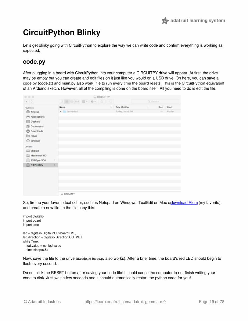
After plugging in a board with CircuitPython into your computer a CIRCUITPY drive will appear. At first, the drivemay be empty but you can create and edit files on it just like you would on a USB drive. On here, you can save acode.py (code.txt and main.py also work) file to run every time the board resets. This is the CircuitPython equivalentof an Arduino sketch. However, all of the compiling is done on the board itself. All you need to do is edit the file.
So, fire up your favorite text editor, such as Notepad on Windows, TextEdit on Mac or download Atom (my favorite),and create a new file. In the file copy this:
import digitalioimport boardimport time
led = digitalio.DigitalInOut(board.D13)led.direction = digitalio.Direction.OUTPUTwhile True: led.value = not led.value time.sleep(0.5)
Now, save the file to the drive as code.txt (code.py also works). After a brief time, the board's red LED should begin toflash every second.
Do not click the RESET button after saving your code file! It could cause the computer to not-finish writing yourcode to disk. Just wait a few seconds and it should automatically restart the python code for you!
© Adafruit Industries https://learn.adafruit.com/adafruit-gemma-m0 Page 19 of 78

Status LED
While code.py is running the status neopixel will be solid green. After it is finished, the neopixel will fade green onsuccess or flash an error code on failure. Red flashes happen when data is written to the drive.
Debugging
Did the status LED flash a bunch of colors at you? You may have an error in your code. Don't worry it happens toeveryone. Python code is checked when you run it rather than before like Arduino does when it compiles. To seethe CircuitPython error you'll need to connect to the serial output (like Arduino's serial monitor).
See this guide for detailed instructions.
If you are new to Python try googling the error first, if that doesn't find an answer feel free to drop by the supportforum.
Libraries
Using libraries with CircuitPython is also super easy. Simply drag and drop libraries onto the CIRCUITPY drive orinto a lib folder on the drive to keep it tidy.
Find CircuitPython libraries on GitHub using the topic and through our tutorials.
Make sure the libraries are for CircuitPython and not MicroPython. There are some differences that may cause it tonot work as expected.
More infoGuides and TutorialsAPI ReferenceAdafruit forumLibraries
© Adafruit Industries https://learn.adafruit.com/adafruit-gemma-m0 Page 20 of 78

Serial Console (REPL)CircuitPython sends the output of the .py files it runs to the connected computer over USB serial. So, to view theoutput of your code from print statements and any errors that occur you'll need to connect to the serial console.
Also, because CircuitPython is a variant of Python, it too has a read-evaluate-print-loop or 'REPL' for short. TheREPL lets you run individual commands and load up code interactively and is therefore great for testing a new idea.However, the code typed into the REPL isn't saved anywhere so make sure and save it elsewhere (like code.py forexample.)
Windows
Serial Drivers (for Windows 7)
If you are using Windows 7 you will need to install drivers. Click below to download the driver package and install it!This is not necessary for Mac, Linux or Windows 10+.
Download Adafruit Windows Driver Installerhttp://adafru.it/yDr
Determine Your Serial Port
Next you must determine the name of the serial port for your board. It's easiest to look at the serial ports with theboard disconnected (on Windows check Device Manager under the Ports (COM/LPT) node
It will be named something like Adafruit Trinket M0 or Adafruit Feather M0
© Adafruit Industries https://learn.adafruit.com/adafruit-gemma-m0 Page 21 of 78

Install Serial Port Terminal Software
On Windows you'll want to use a tool like PuTTY (http://adafru.it/pNe) to connect to the serial port. Download andrun PuTTY, then configure it to use a serial connection to the board's COM port at 115200 baud similar to as shownbelow:
© Adafruit Industries https://learn.adafruit.com/adafruit-gemma-m0 Page 22 of 78

After clicking Open you should see a new window pop up with the current output from the running code. If no codeis running, it may be blank so hit Ctrl - C to get to the REPL prompt.
Mac OSX and LinuxConnecting to the serial terminal on is more straightforward than on Windows. Neither OS requires additionaldrivers.
First open a terminal program. On Mac OSX, Terminal comes installed and iTerm2 (http://adafru.it/xZd) can bedownloaded. On Linux there are a variety available such as gnome-terminal (called Terminal) and Konsole on KDE.
Now before plugging in the board, type ls /dev/tty.* to view existing serial connections.
Next, plug in the board. There should be one new serial connection that is for your board. Typically on Mac OSX itssomething like /dev/tty.usbmodem* and on Linux its /dev/ttyACM*.
© Adafruit Industries https://learn.adafruit.com/adafruit-gemma-m0 Page 23 of 78
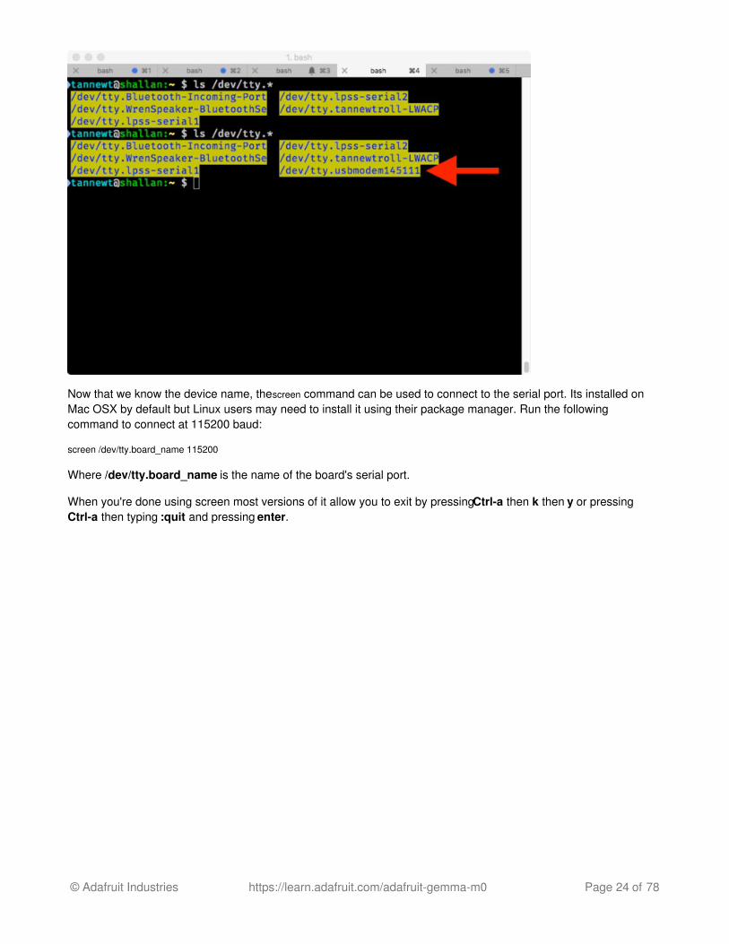
Now that we know the device name, the screen command can be used to connect to the serial port. Its installed onMac OSX by default but Linux users may need to install it using their package manager. Run the followingcommand to connect at 115200 baud:
screen /dev/tty.board_name 115200
Where /dev/tty.board_name is the name of the board's serial port.
When you're done using screen most versions of it allow you to exit by pressing Ctrl-a then k then y or pressingCtrl-a then typing :quit and pressing enter.
© Adafruit Industries https://learn.adafruit.com/adafruit-gemma-m0 Page 24 of 78

Using the REPLAfter you're connected to the serial REPL try pressing enter to confirm you see the >>> prompt. You can also typehelp() and press enter on most boards to see basic usage information.
If you can't get a >>> prompt to appear try pressing Ctrl-c a couple times to interrupt any running program on theboard.
You might get a Traceback and KeyboardInterrupt that lets you know the current Python program has stopped,and you'll get a prompt:
© Adafruit Industries https://learn.adafruit.com/adafruit-gemma-m0 Page 25 of 78

That's all there is to connecting to the board's serial REPL, you're ready to start typing in and running CircuitPythoncode!
© Adafruit Industries https://learn.adafruit.com/adafruit-gemma-m0 Page 26 of 78

Installing LibrariesPart of what makes CircuitPython so awesome is its ability to store code separately from the firmware itself. Storingcode separately from the firmware makes it easier to update both the code you write and the libraries you depend.So, instead of compiling libraries in, you simply place them into your lib directory on the CIRCUITPY drive.
Your board ships with a lib folder already, its in the base directory of the drive:
CircuitPython libraries work in the same was as regular Python modules so the Python docs are a great referencefor how it all should work. In Python terms, we can place our library files in the lib directory because its part of thePython path by default.
One downside of this approach of separate libraries is that they are not built in. To use them, one needs to copythem to the CIRCUITPY drive before they can be used. Fortunately, we provide a bundle full of our libraries.
Our bundle and releases also feature optimized versions of the libraries with the .mpy file extension. These files takeless space on the drive and have a smaller memory footprint as they are loaded.
Installing the bundle
The board's tiny size means we weren't able to fit extra flash memory on it. Thats why the drive is less that 64kbtotal! Its the microcontroller itself thats saving the data, in the internal 256KB flash space - about 192KB for thebootloader and Python interpreter and about 64KB for user code.
We need to be selective about what libraries we load on the board because we can't simply fit them all like we canon an Express board. So, lets take a look at this silly example below which uses a SI7021 I2C temperature sensor.
import adafruit_si7021import busio
© Adafruit Industries https://learn.adafruit.com/adafruit-gemma-m0 Page 27 of 78

import board
i2c = busio.I2C(board.SCL, board.SDA)sensor = adafruit_si7021.SI7021(i2c)print("Temperature:", sensor.temperature)print("Humidity:", sensor.relative_humidity)
After saving that as code.py on the drive we see the status NeoPixel flashes that an error has occurred. Opening upthe serial console we see that an ImportError has occurred.
It says that no module exists named adafruit_si7021. Thats the library we need to download! Since we bought thesensor from Adafruit its likely there is a library for in the official Adafruit bundle. If its not an Adafruit part or itsmissing, we can also check the Community bundle which has libraries contributed by the community.
Click for the latest Adafruit Bundle releasehttp://adafru.it/y8E
Visiting the bundle release page will show us information on the latest release including a list of all the versions ofthe included drivers. Scrolling to the bottom of the page will reveal the downloads. We'll download the first zip filewhich starts with adafruit-circuitpython-bundle.
© Adafruit Industries https://learn.adafruit.com/adafruit-gemma-m0 Page 28 of 78

After downloading the zip, extract its contents. This is usually done by double clicking on the zip. On Mac OSX asI'm using, it places the file in the same directory as the zip. I usually sort my Downloads by file data so the libdirectory that was contained in the zip ends up next to the zip file.
© Adafruit Industries https://learn.adafruit.com/adafruit-gemma-m0 Page 29 of 78

On Express boards, the lib directory can be copied directly to the CIRCUITPY drive. However, this board doesn'thave enough space for all of the libraries. So, we'll copy over just what we need as we need it. In the lib folder thereis an adafruit_si7021.mpy file. That matches the missing module! Python imports modules based on the filename sothey will always match up. Lets drag it over. If this works, skip to the next section. Keep reading if you have an error.
Out of space!
The file system on the board is very tiny. (Smaller than an ancient floppy disk.) So, its likely you'll run out of spacebut don't panic! There are a couple ways to free up space.
The board ships with the Windows 7 serial driver too! Feel free to delete that if you don't need it or have alreadyinstalled it. Its ~12KiB or so.
© Adafruit Industries https://learn.adafruit.com/adafruit-gemma-m0 Page 30 of 78

Delete something!
The simplest way of freeing up space is to delete files from the drive. Perhaps there are libraries in the lib that youaren't using anymore or test code that isn't in use.
Use tabs
One unique feature of Python is that the indentation of code matters. Usually the recommendation is to indent codewith four spaces for every indent. In general, we recommend that too. However, one trick to storing more human-readable code is to use a single tab character for indentation. This approach uses 1/4 of the space for indentationand can be significant when we're counting bytes.
Mac OSX loves to add extra files.
Luckily you can disable some of the extra hidden files that Mac OSX adds by running a few commands to disablesearch indexing and create zero byte placeholders. Follow the steps below to maximize the amount of spaceavailable on OSX:
Prevent & Remove Mac OSX Hidden Files
First find the volume name for your board. With the board plugged in run this command in a terminal to list all thevolumes:
ls -l /Volumes
Look for a volume with a name like CIRCUITPY (the default for CircuitPython). The full path to the volume isthe /Volumes/CIRCUITPY path.
Now follow the steps from this question (http://adafru.it/u1c) to run these terminal commands that stop hidden filesfrom being created on the board:
mdutil -i off /Volumes/CIRCUITPYcd /Volumes/CIRCUITPYrm -rf .{,_.}{fseventsd,Spotlight-V*,Trashes}mkdir .fseventsdtouch .fseventsd/no_log .metadata_never_index .Trashescd -
Replace /Volumes/CIRCUITPY in the commands above with the full path to your board's volume if it's different. Atthis point all the hidden files should be cleared from the board and some hidden files will be prevented from beingcreated.
However there are still some cases where hidden files will be created by Mac OSX. In particular if you copy a filethat was downloaded from the internet it will have special metadata that Mac OSX stores as a hidden file. Luckilyyou can run a copy command from the terminal to copy files without this hidden metadata file. See the stepsbelow:
© Adafruit Industries https://learn.adafruit.com/adafruit-gemma-m0 Page 31 of 78

Copy Files on Mac OSX Without Creating Hidden Files
Once you've disabled and removed hidden files with the above commands on Mac OSX you need to be careful tocopy files to the board with a special command that prevents future hidden files from being created. Unfortunatelyyou cannot use drag and drop copy in Finder because it will still create these hidden extended attribute files insome cases (for files downloaded from the internet, like Adafruit's modules).
To copy a file or folder use the -X option for the cp command in a terminal. For example to copy a foo.mpy file tothe board use a command like:
cp -X foo.mpy /Volumes/CIRCUITPY
Or to copy a folder and all of its child files/folders use a command like:
cp -rX folder_to_copy /Volumes/CIRCUITPY
Other Mac OSX Tips
If you'd like to see the amount of space used on the drive and manually delete hidden files here's how to do so. First list the amount of space used on the CIRCUITPY drive with the df command:
Lets remove the ._ files first.
© Adafruit Industries https://learn.adafruit.com/adafruit-gemma-m0 Page 32 of 78

Whoa! We have 13Ki more than before! Lets continue!
Continuing after copy
Woohoo! Everything copied over just fine. Lets check the serial terminal to see how things are going.
Oops! Another ImportError! Libraries can depend on other libraries so copying one file over may not be enough.Looking in the bundle, there is an adafruit_bus_device directory. In Python terms this is a package. It contains modulefiles. Lets copy the folder over to make sure we get everything.
© Adafruit Industries https://learn.adafruit.com/adafruit-gemma-m0 Page 33 of 78

If that fails due to out of space, see above. If not, continue on.
Lets check the serial connection again. Looks like it worked! We don't have any more ImportErrors and we can see thetemperature (in Celsius) and the relative humidity.
© Adafruit Industries https://learn.adafruit.com/adafruit-gemma-m0 Page 34 of 78

CircuitPython Analog InThis quick-start example shows how you can read the analog voltages on all three Gemma M0 pads.
Copy and paste the code block into main.py using your favorite text editor, and save the file, to run the demo
# Gemma IO demo - analog inputs
from digitalio import *from analogio import *from board import *import time
led = DigitalInOut(L)led.direction = Direction.OUTPUT
analog0in = AnalogIn(A0)analog1in = AnalogIn(A1)analog2in = AnalogIn(A2)
def getVoltage(pin): return (pin.value * 3.3) / 65536
while True: print("A0: %f \t\t A1: %f \t\t A2: %f" % (getVoltage(analog0in), getVoltage(analog1in), getVoltage(analog2in)))
time.sleep(0.1)
Creating analog inputs
analog0in = AnalogIn(A0) analog1in = AnalogIn(A1) analog2in = AnalogIn(A2)
Creates three objects, one for each pad, and connects the objects to A0, A1 and A2 as analog inputs.
GetVoltage Helper
getVoltage(pin) is our little helper program. By default, analog readings will range from 0 (minimum) to 65535(maximum). This helper will convert the 0-65535 reading from pin.value and convert it a 0-3.3V voltage reading.
Main Loop
The main loop is simple, it will just print out the three voltages as floating point values (the %f indicates to print asfloating point) by calling getVoltage on each of our analog objects.
If you connect to the serial port REPL, you'll see the voltages printed out. By default the pins are floating so thevoltages will vary. Try touching a wire from A0 to the GND or 3Vo pad to see the voltage change!
© Adafruit Industries https://learn.adafruit.com/adafruit-gemma-m0 Page 35 of 78

© Adafruit Industries https://learn.adafruit.com/adafruit-gemma-m0 Page 36 of 78

CircuitPython Analog OutThis quick-start example shows how you can set the DAC (true analog voltage output) on all Gemma M0 pad A0.
Copy and paste the code block into main.py using your favorite text editor, and save the file, to run the demo
# Gemma IO demo - analog output from digitalio import *from analogio import *from board import *import time aout = AnalogOut(A0) while True: # Count up from 0 to 65535, with 64 increment # which ends up corresponding to the DAC's 10-bit range for i in range (0,65535,64): aout.value = i
Creating an analog output
aout = AnalogOut(A0)
Creates an object aout that is connected to the only DAC pin available - A0.
Setting the analog output
The DAC on the Gemma M0 is a 10-bit output, from 0-3.3V. So in theory you will have a resolution of 0.0032 Voltsper bit. To allow CircuitPython to be general-purpose enough that it can be used with chips with anything from 8 to16-bit DACs, the DAC takes a 16-bit value and divides it down internally.
E.g. writing 0 will be the same as setting it to 0 - 0 Volts out
Writing 5000 is the same as setting it to 5000 / 64 = 78And 78 / 1024 * 3.3V = 0.25V output
Writing 65535 is the same as 1023 which is the top range and you'll get 3.3V output
Main Loop
The main loop is fairly simple, it just goes through the entire range of the DAC, from 0 to 65535, but increments 64at a time so it ends up clicking up one bit for each of the 10-bits of range available.
CircuitPython is not terribly fast, so at the fastest update loop you'll get 4 Hz. The DAC isn't good for audio outputsas-is.
Bigger boards like the Metro or Feather M0 have more code space and can perform audio playback capabilities viathe DAC.
© Adafruit Industries https://learn.adafruit.com/adafruit-gemma-m0 Page 37 of 78

© Adafruit Industries https://learn.adafruit.com/adafruit-gemma-m0 Page 38 of 78

CircuitPython Cap TouchThis quick-start example shows how you can read the capacitive touch sensors built into on all three Gemma M0pads.
Copy and paste the code block into main.py using your favorite text editor, and save the file, to run the demo
# Gemma IO demo - captouch
import touchiofrom board import *import time
touch0 = touchio.TouchIn(A0)touch1 = touchio.TouchIn(A1)touch2 = touchio.TouchIn(A2)
while True: if touch0.value: print("A0 touched!") if touch1.value: print("A1 touched!") if touch2.value: print("A2 touched!") time.sleep(0.01)
You can open up the serial console to see the touches detected and printed out.
© Adafruit Industries https://learn.adafruit.com/adafruit-gemma-m0 Page 39 of 78

Creating an capacitive touch input
All three pads can be used as capacitive TouchIn devices:
touch0 = touchio.TouchIn(A0)touch1 = touchio.TouchIn(A1)touch2 = touchio.TouchIn(A2)
Creates three objects, one connected to each of the Gemma M0 pads.
Main Loop
The main loop checks each sensor one after the other, to determine if it has been touched. If touch0.value returnsTrue, that means that that pad, A0, detected a touch. For each pad, if it has been touched, a message will print.
A small sleep delay is added at the end so the loop doesn't run too fast. You may want to change the delay from 0.1seconds to 0 seconds to slow it down or speed it up.
Note that no extra hardware is required, you can touch the pads directly, but you may want to attach alligator clipsor foil tape to metallic or conductive objects. Try silverware, fruit or other food, liquid, aluminum foil, and itemsaround your desk!
© Adafruit Industries https://learn.adafruit.com/adafruit-gemma-m0 Page 40 of 78

You may need to restart your code/board after changing the attached item because the capacitive touch code'calibrates' based on what it sees when it first starts up. So if you get too many touch-signals or not enough, hit thatreset button!
Copper Foil Tape with Conductive Adhesive - 6mm x 15 meter roll
PRODUCT ID: 1128Copper tape can be an interesting addition to your toolbox. The tape itself is made of thin pure copper so itsextremely flexible and can take on nearly any shape. You can easily solder...http://adafru.it/eNZ$5.95IN STOCK
© Adafruit Industries https://learn.adafruit.com/adafruit-gemma-m0 Page 41 of 78

Copper Foil Tape with Conductive Adhesive - 25mm x 15 meter roll
PRODUCT ID: 1127Copper tape can be an interesting addition to your toolbox. The tape itself is made of thin pure copper so itsextremely flexible and can take on nearly any shape. You can easily solder...http://adafru.it/y8F$19.95IN STOCK
Small Alligator Clip Test Lead (set of 12)
PRODUCT ID: 1008Connect this to that without soldering using these handy mini alligator clip test leads. 15" cables with alligator clip oneach end, color coded. You get 12 pieces in 6 colors....http://adafru.it/dWJ$3.95IN STOCK
© Adafruit Industries https://learn.adafruit.com/adafruit-gemma-m0 Page 42 of 78

CircuitPython Touch-DotStarThis quick-start example builds upon the previous example, but shows how you can create interactivity usingcapacitive touch. It also demonstrates the built in DotStar LED and how you can change the color on your own.
Copy and paste the code block into main.py using your favorite text editor, and save the file, to run the demo
# Gemma IO demo - captouch to dotstar
import touchioimport busiofrom board import *import time
dotstar = busio.SPI(APA102_SCK, APA102_MOSI)touch0 = touchio.TouchIn(A0)touch1 = touchio.TouchIn(A1)touch2 = touchio.TouchIn(A2)
r = g = b = 0
def setPixel(red, green, blue): if not dotstar.try_lock(): return print("setting pixel to: %d %d %d" % (red, green, blue))
data = bytearray([0x00, 0x00, 0x00, 0x00, 0xff, blue, green, red, 0xff, 0xff, 0xff, 0xff]) dotstar.write(data) dotstar.unlock() time.sleep(0.01)
while True: if touch0.value: r = (r+1) % 256 if touch1.value: g = (g+1) % 256 if touch2.value: b = (b+1) % 256
setPixel(r, g, b)
Each of the three pads will change the color of the built in mini DotStar LED. You can touch each pad in order tosee the LED change colors, or you can open up the serial console to see the touches detected and the pixel colorprinted out.
© Adafruit Industries https://learn.adafruit.com/adafruit-gemma-m0 Page 43 of 78

© Adafruit Industries https://learn.adafruit.com/adafruit-gemma-m0 Page 44 of 78

CircuitPython UART SerialThis quick-start example shows how you can create a UART device for communicating with hardware serial devices
Copy and paste the code block into main.py using your favorite text editor, and save the file, to run the demo
# Gemma IO demo - USB/Serial echo
from digitalio import *from board import *import busioimport time
led = DigitalInOut(D13)led.direction = Direction.OUTPUT
uart = busio.UART(D0, D2, baudrate=9600)
while True: data = uart.read(32) # read up to 32 bytes #print(data) # this is a bytearray type
if data != None: led.value = True
datastr = ''.join([chr(b) for b in data]) # convert bytearray to string print(datastr, end="")
led.value = False
In addition to the USB-serial connection you use for the REPL, there is also a hardware UART you can use. This ishandy to talk to UART devices like GPS's, some sensors, or other microcontrollers!
You can create a new UART object with uart = busio.UART(D0, D2, baudrate=9600) You can use only D0 and D2 as thetransmitting and receiving pins on the Gemma M0. Set the baudrate to whatever you like.
Once the object is created you read data in with read(numbytes) where you can specify the max number of bytes. It willreturn a bytearray type object if anything was received already. Note it will always return immediately because thereis an internal buffer! So read as much data as you can 'digest'.
If there is no data available, read() will return None, so check for that before continuing.
The data that is returned is in a byte array, if you want to convert it to a string, you can use this handy line of codewhich will run chr() on each byte:
datastr = ''.join([chr(b) for b in data]) # convert bytearray to string
For more UART details, check out the module documentation!http://adafru.it/yCH
To run this demo, you'll need something to generate UART data. We connected up a GPS!
© Adafruit Industries https://learn.adafruit.com/adafruit-gemma-m0 Page 45 of 78

gemma + gps Fritzing Filehttp://adafru.it/yCI
© Adafruit Industries https://learn.adafruit.com/adafruit-gemma-m0 Page 46 of 78

© Adafruit Industries https://learn.adafruit.com/adafruit-gemma-m0 Page 47 of 78

CircuitPython I2C ScanThis quick-start example shows how you can use CircuitPython to scan the I2C bus for all connected devices
Copy and paste the code block into main.py using your favorite text editor, and save the file, to run the demo
# Gemma IO demo - I2C scan
from digitalio import *from board import *import busioimport time
led = DigitalInOut(D13)led.direction = Direction.OUTPUT
i2c = busio.I2C(D2, D0)
while True: print("I2C addresses found:", [hex(i) for i in i2c.scan()]) time.sleep(2)
You can also use the Gemma to chat with I2C sensors and devices. Before you start, we recommend connecting itup and doing an I2C scan so you can tell if it was detected.
You can create the I2C devices on the Gemma M0's D2 (SCL) and D0 (SDA) pins.
Then run a scan with i2c.scan() It will return an array of addresses, but since usually they are referred to in hexformat, you may want to convert the array to hexadecimals with [hex(i) for i in i2c.scan()])
© Adafruit Industries https://learn.adafruit.com/adafruit-gemma-m0 Page 48 of 78

We wired up a Flora TSL2561 breakout with address 0x39 to test it!
© Adafruit Industries https://learn.adafruit.com/adafruit-gemma-m0 Page 49 of 78

Gemma + TSL Fritzing Filehttp://adafru.it/yCJ
© Adafruit Industries https://learn.adafruit.com/adafruit-gemma-m0 Page 50 of 78

CircuitPython I2C Sensor# Gemma M0 IO Demo - I2C demo
from digitalio import *from board import *import busioimport adafruit_si7021import time
led = DigitalInOut(D13)led.direction = Direction.OUTPUT
i2c = busio.I2C(D2, D0)print("I2C addresses found:", [hex(i) for i in i2c.scan()])
si7021 = adafruit_si7021.SI7021(i2c)
while True: print("Temp: %0.2F *C Humidity: %0.1F %%" % (si7021.temperature, si7021.relative_humidity)) time.sleep(1)
We used our Alligator-to-breadboard wires to connect up the Gemma to a Si7021 breakout
© Adafruit Industries https://learn.adafruit.com/adafruit-gemma-m0 Page 51 of 78

Small Alligator Clip to Male Jumper Wire Bundle - 12 Pieces
PRODUCT ID: 3255For bread-boarding with unusual non-header-friendly surfaces, these cables will be your best friends! No longer willyou have long strands of alligator clips that are grabbing little...http://adafru.it/xAV$7.95IN STOCK
Adafruit Si7021 Temperature & Humidity Sensor Breakout Board
PRODUCT ID: 3251It's summer and you're sweating and your hair's all frizzy and all you really want to know is why the weathermansaid this morning that today's relative humidity would max...http://adafru.it/y6F$6.95IN STOCK
Then check the REPL. If you have not yet used this chip you may get an ImportError: no module named'adafruit_si7021'
© Adafruit Industries https://learn.adafruit.com/adafruit-gemma-m0 Page 52 of 78

That means you need to install the Adafruit_Si7021 library that gives you the friendly interface we use above.
Check out our page on Installing Libraries to learn how to download the driver bundle and drag the driver youneed to the lib folder (http://adafru.it/yCK)
You will also need the adafruit_bus_device library folder - that will give you I2C access in a nice manner!
Once you're done you'll see you have the libraries installed:
Finally if you re-run you will be able to see the temperature and humidity data from the sensor:
© Adafruit Industries https://learn.adafruit.com/adafruit-gemma-m0 Page 53 of 78

Handy Tips
Check Heap Memory Usageimport gc
gc.free_mem()
Will give you the number of bytes available for use.
Random Numbersimport urandom
urandom.random() will give a floating point number from 0 to 1.0
urandom.randint(min, max) will give you an integer number between min and max
© Adafruit Industries https://learn.adafruit.com/adafruit-gemma-m0 Page 54 of 78

Arduino IDE SetupThe first thing you will need to do is to download the latest release of the Arduino IDE. You will need to be usingversion 1.8 or higher for this guide
Arduino IDE Downloadhttp://adafru.it/f1P
After you have downloaded and installed the latest version of Arduino IDE, you will need to start the IDE andnavigate to the Preferences menu. You can access it from the File menu in Windows or Linux, or the Arduinomenu on OS X.
A dialog will pop up just like the one shown below.
© Adafruit Industries https://learn.adafruit.com/adafruit-gemma-m0 Page 55 of 78

We will be adding a URL to the new Additional Boards Manager URLs option. The list of URLs is commaseparated, and you will only have to add each URL once. New Adafruit boards and updates to existing boards willautomatically be picked up by the Board Manager each time it is opened. The URLs point to index files that theBoard Manager uses to build the list of available & installed boards.
To find the most up to date list of URLs you can add, you can visit the list of third party board URLs on the ArduinoIDE wiki (http://adafru.it/f7U). We will only need to add one URL to the IDE in this example, but you can addmultiple URLS by separating them with commas. Copy and paste the link below into the Additional BoardsManager URLs option in the Arduino IDE preferences.
https://adafruit.github.io/arduino-board-index/package_adafruit_index.json
© Adafruit Industries https://learn.adafruit.com/adafruit-gemma-m0 Page 56 of 78

Here's a short description of each of the Adafruit supplied packages that will be available in the Board Managerwhen you add the URL:
Adafruit AVR Boards - Includes support for Flora, Gemma, Feather 32u4, Trinket, & Trinket Pro.Adafruit SAMD Boards - Includes support for Feather M0, Metro M0, Circuit Playground Express, GemmaM0 and Trinket M0Arduino Leonardo & Micro MIDI-USB - This adds MIDI over USB support for the Flora, Feather 32u4, Microand Leonardo using the arcore project (http://adafru.it/eSI).
If you have multiple boards you want to support, say ESP8266 and Adafruit, have both URLs in the text boxseparated by a comma (,)
Once done click OK to save the new preference settings. Next we will look at installing boards with the BoardManager.
Now continue to the next step to actually install the board support package!
© Adafruit Industries https://learn.adafruit.com/adafruit-gemma-m0 Page 57 of 78

Using with Arduino IDESince the Feather/Metro/Gemma/Trinket M0 use an ATSAMD21 chip running at 48 MHz, you can pretty easily get itworking with the Arduino IDE. Most libraries (including the popular ones like NeoPixels and display) will work withthe M0, especially devices & sensors that use i2c or SPI.
Now that you have added the appropriate URLs to the Arduino IDE preferences in the previous page, you can openthe Boards Manager by navigating to the Tools->Board menu.
Once the Board Manager opens, click on the category drop down menu on the top left hand side of the window andselect Contributed. You will then be able to select and install the boards supplied by the URLs added to theprefrences.
Install SAMD SupportFirst up, install the Arduino SAMD Boards version 1.6.15 or later
You can type Arduino SAMD in the top search bar, then when you see the entry, click Install
© Adafruit Industries https://learn.adafruit.com/adafruit-gemma-m0 Page 58 of 78

Install Adafruit SAMDNext you can install the Adafruit SAMD package to add the board file definitions
You can type Adafruit SAMD in the top search bar, then when you see the entry, click Install
Even though in theory you don't need to - I recommend rebooting the IDE
Quit and reopen the Arduino IDE to ensure that all of the boards are properly installed. You should now be able toselect and upload to the new boards listed in the Tools->Board menu.
Select the matching board, the current options are:
Feather M0 (for use with any Feather M0 other than the Express)Feather M0 ExpressMetro M0 ExpressCircuit Playground ExpressGemma M0Trinket M0
Install Drivers (Windows 7 Only)
© Adafruit Industries https://learn.adafruit.com/adafruit-gemma-m0 Page 59 of 78

When you plug in the board, you'll need to possibly install a driver
Click below to download our Driver Installer
Download Adafruit Driver Installer v1.5http://adafru.it/yDr
Download and run the installer
Run the installer! Since we bundle the SiLabs and FTDI drivers as well, you'll need to click through the license
Select which drivers you want to install, the defaults will set you up with just about every Adafruit board!
© Adafruit Industries https://learn.adafruit.com/adafruit-gemma-m0 Page 60 of 78

Click Install to do the installin'
BlinkNow you can upload your first blink sketch!
Plug in the Gemma M0, Trinket M0, Metro M0 or Feather M0 and wait for it to be recognized by the OS (just takes afew seconds). It will create a serial/COM port, you can now select it from the dropdown, it'll even be 'indicated' asTrinket/Gemma/Metro/Feather M0!
Now load up the Blink example
// the setup function runs once when you press reset or power the boardvoid setup() { // initialize digital pin 13 as an output. pinMode(13, OUTPUT);}
// the loop function runs over and over again forevervoid loop() { digitalWrite(13, HIGH); // turn the LED on (HIGH is the voltage level) delay(1000); // wait for a second digitalWrite(13, LOW); // turn the LED off by making the voltage LOW delay(1000); // wait for a second}
And click upload! That's it, you will be able to see the LED blink rate change as you adapt the delay() calls.
© Adafruit Industries https://learn.adafruit.com/adafruit-gemma-m0 Page 61 of 78

If you are having issues, make sure you selected the matching Board in the menu that matches the hardware youhave in your hand.
Sucessful UploadIf you have a successful upload, you'll get a bunch of red text that tells you that the device was found and it wasprogrammed, verified & reset
Compilation IssuesIf you get an alert that looks like
Cannot run program "{runtime.tools.arm-none-eabi-gcc.path}\bin\arm-non-eabi-g++"
Make sure you have installed the Arduino SAMD boards package, you need both Arduino & Adafruit SAMD boardpackages
© Adafruit Industries https://learn.adafruit.com/adafruit-gemma-m0 Page 62 of 78

Manually bootloadingIf you ever get in a 'weird' spot with the bootloader, or you have uploaded code that crashes and doesn't auto-rebootinto the bootloader, click the RST button twice (like a double-click)to get back into the bootloader.
The red LED will pulse, so you know that its in bootloader mode.
Once it is in bootloader mode, you can select the newly created COM/Serial port and re-try uploading.
You may need to go back and reselect the 'normal' USB serial port next time you want to use the normal upload.
Ubuntu & Linux Issue FixNote if you're using Ubuntu 15.04 (or perhaps other more recent Linux distributions) there is an issue with themodem manager service which causes the Bluefruit LE micro to be difficult to program. If you run into errors like"device or resource busy", "bad file descriptor", or "port is busy" when attempting to program then you are hittingthis issue. (http://adafru.it/sHE)
The fix for this issue is to make sure Adafruit's custom udev rules are applied to your system. One of these rules ismade to configure modem manager not to touch the Feather board and will fix the programming difficulty issue. Follow the steps for installing Adafruit's udev rules on this page. (http://adafru.it/iOE)
© Adafruit Industries https://learn.adafruit.com/adafruit-gemma-m0 Page 63 of 78

Adapting Sketches to M0The ATSAMD21 is a very nice little chip but its fairly new as Arduino-compatible cores go. Most sketches & librarieswill work but here's a few things we noticed!
The below note are for all M0 boards, but not all may apply (e.g. Trinket and Gemma M0 do not have ARef so youcan skip the Analog References note!)
Analog ReferencesIf you'd like to use the ARef pin for a non-3.3V analog reference, the code to use is analogReference(AR_EXTERNAL) (it'sAR_EXTERNAL not EXTERNAL)
Pin Outputs & PullupsThe old-style way of turning on a pin as an input with a pullup is to use
pinMode(pin, INPUT)digitalWrite(pin, HIGH)
This is because the pullup-selection register is the same as the output-selection register.
For the M0, you can't do this anymore! Instead, use
pinMode(pin, INPUT_PULLUP)
which has the benefit of being backwards compatible with AVR.
Serial vs SerialUSB99.9% of your existing Arduino sketches use Serial.print to debug and give output. For the Official ArduinoSAMD/M0 core, this goes to the Serial5 port, which isn't exposed on the Feather. The USB port for the OfficialArduino M0 core, is called SerialUSB instead.
In the Adafruit M0 Core, we fixed it so that Serial goes to USB when you use a Feather M0 so it will automaticallywork just fine.
However, on the off chance you are using the official Arduino SAMD core not the Adafruit version (whichreally, we recommend you use our version because as you can see it can vary) & you want your Serialprints and reads to use the USB port, use SerialUSB instead of Serial in your sketch
If you have existing sketches and code and you want them to work with the M0 without a huge find-replace, put
#if defined(ARDUINO_SAMD_ZERO) && defined(SERIAL_PORT_USBVIRTUAL) // Required for Serial on Zero based boards #define Serial SERIAL_PORT_USBVIRTUAL#endif
right above the first function definition in your code. For example:
© Adafruit Industries https://learn.adafruit.com/adafruit-gemma-m0 Page 64 of 78

AnalogWrite / PWM on Feather/Metro M0After looking through the SAMD21 datasheet, we've found that some of the options listed in the multiplexer tabledon't exist on the specific chip used in the Feather M0.
For all SAMD21 chips, there are two peripherals that can generate PWM signals: The Timer/Counter (TC) andTimer/Counter for Control Applications (TCC). Each SAMD21 has multiple copies of each, called 'instances'.
Each TC instance has one count register, one control register, and two output channels. Either channel can beenabled and disabled, and either channel can be inverted. The pins connected to a TC instance can output identicalversions of the same PWM waveform, or complementary waveforms.
Each TCC instance has a single count register, but multiple compare registers and output channels. There areoptions for different kinds of waveform, interleaved switching, programmable dead time, and so on.
The biggest members of the SAMD21 family have five TC instances with two 'waveform output' (WO) channels, andthree TCC instances with eight WO channels:
TC[0-4],WO[0-1]TCC[0-2],WO[0-7]
And those are the ones shown in the datasheet's multiplexer tables.
The SAMD21G used in the Feather M0 only has three TC instances with two output channels, and three TCCinstances with eight output channels:
TC[3-5],WO[0-1]TCC[0-2],WO[0-7]
Tracing the signals to the pins broken out on the Feather M0, the following pins can't do PWM at all:
Analog pin A5
The following pins can be configured for PWM without any signal conflicts as long as the SPI, I2C, and UART pinskeep their protocol functions:
Digital pins 5, 6, 9, 10, 11, 12, and 13Analog pins A3 and A4
If only the SPI pins keep their protocol functions, you can also do PWM on the following pins:
TX and SDA (Digital pins 1 and 20)
© Adafruit Industries https://learn.adafruit.com/adafruit-gemma-m0 Page 65 of 78
analogWrite() PWM rangeOn AVR, if you set a pin's PWM with analogWrite(pin, 255) it will turn the pin fully HIGH. On the ARM cortex, it will set itto be 255/256 so there will be very slim but still-existing pulses-to-0V. If you need the pin to be fully on, add testcode that checks if you are trying to analogWrite(pin, 255) and, instead, does a digitalWrite(pin, HIGH)
Missing header filesthere might be code that uses libraries that are not supported by the M0 core. For example if you have a line with
#include <util/delay.h>
you'll get an error that says
fatal error: util/delay.h: No such file or directory #include <util/delay.h> ^compilation terminated.Error compiling.
In which case you can simply locate where the line is (the error will give you the file name and line number) and'wrap it' with #ifdef's so it looks like:
#if !defined(ARDUINO_ARCH_SAM) && !defined(ARDUINO_ARCH_SAMD) && !defined(ESP8266) && !defined(ARDUINO_ARCH_STM32F2) #include <util/delay.h>#endif
The above will also make sure that header file isn't included for other architectures
If the #include is in the arduino sketch itself, you can try just removing the line.
Bootloader LaunchingFor most other AVRs, clicking reset while plugged into USB will launch the bootloader manually, the bootloader willtime out after a few seconds. For the M0, you'll need to double click the button. You will see a pulsing red LED to letyou know you're in bootloader mode. Once in that mode, it wont time out! Click reset again if you want to go back tolaunching code
Aligned Memory AccessThis is a little less likely to happen to you but it happened to me! If you're used to 8-bit platforms, you can do thisnice thing where you can typecast variables around. e.g.
uint8_t mybuffer[4];float f = (float)mybuffer;
You can't be guaranteed that this will work on a 32-bit platform because mybuffer might not be aligned to a 2 or 4-byte boundary. The ARM Cortex-M0 can only directly access data on 16-bit boundaries (every 2 or 4 bytes). Tryingto access an odd-boundary byte (on a 1 or 3 byte location) will cause a Hard Fault and stop the MCU. Thankfully,there's an easy work around ... just use memcpy!
uint8_t mybuffer[4];float f;memcpy(f, mybuffer, 4)
© Adafruit Industries https://learn.adafruit.com/adafruit-gemma-m0 Page 66 of 78
Floating Point ConversionLike the AVR Arduinos, the M0 library does not have full support for converting floating point numbers to ASCIIstrings. Functions like sprintf will not convert floating point. Fortunately, the standard AVR-LIBC library includes thedtostrf function which can handle the conversion for you.
Unfortunately, the M0 run-time library does not have dtostrf. You may see some references to using #include<avr/dtostrf.h> to get dtostrf in your code. And while it will compile, it does not work.
Instead, check out this thread to find a working dtostrf function you can include in your code:
http://forum.arduino.cc/index.php?topic=368720.0 (http://adafru.it/lFS)
How Much RAM Available?The ATSAMD21G18 has 32K of RAM, but you still might need to track it for some reason. You can do so with thishandy function:
extern "C" char *sbrk(int i);
int FreeRam () { char stack_dummy = 0; return &stack_dummy - sbrk(0);}
Thx to http://forum.arduino.cc/index.php?topic=365830.msg2542879#msg2542879 (http://adafru.it/m6D) for the tip!
Storing data in FLASHIf you're used to AVR, you've probably used PROGMEM to let the compiler know you'd like to put a variable orstring in flash memory to save on RAM. On the ARM, its a little easier, simply add const before the variable name:
const char str[] = "My very long string";
That string is now in FLASH. You can manipulate the string just like RAM data, the compiler will automatically readfrom FLASH so you dont need special progmem-knowledgeable functions.
You can verify where data is stored by printing out the address:Serial.print("Address of str $"); Serial.println((int)&str, HEX);
If the address is $2000000 or larger, its in SRAM. If the address is between $0000 and $3FFFF Then it is in FLASH
© Adafruit Industries https://learn.adafruit.com/adafruit-gemma-m0 Page 67 of 78

UF2 Bootloader DetailsThis is an information page for advanced users who are curious how we get code from your computer into yourExpress board!
Adafruit Express and Gemma/Trinket M0 boards feature an improved bootloader that makes it easier than ever toflash different code onto the microcontroller. This bootloader makes it easy to switch between Microsoft MakeCode,CircuitPython and Arduino.
Instead of needing drivers or a separate program for flashing (say, bossac, jlink or avrdude), one can simply drag a fileonto a removable drive.
The format of the file is a little special. Due to 'operating system woes' you cannot just drag a binary or hex file (trustus, we tried it, it isn't cross-platform compatible). Instead, the format of the file has extra information to help thebootloader know where the data goes. The format is called UF2 (USB Flashing Format). Microsoft MakeCodegenerates UF2s for flashing and CircuitPython releases are also available as UF2. You can also create your ownUF2s from binary files using uf2tool, available here. (http://adafru.it/vPE)
The bootloader is also BOSSA compatible, so it can be used with the Arduino IDE which expects a BOSSAbootloader on ATSAMD-based boards
For more information about UF2, you can read a bunch more at the MakeCode blog (http://adafru.it/w5A), thencheck out the UF2 file format specification (http://adafru.it/vPE) and to build your own bootloader for ATSAMD-based boards, visit Microsoft UF2-SAMD github repository (http://adafru.it/vPF).
The bootloader is not needed when changing your CircuitPython code. Its only needed when upgrading theCircuitPython core or changing between CircuitPython, Arduino and Microsoft MakeCode.
Entering Bootloader ModeThe first step to loading new code onto your board is triggering the bootloader. It is easily done by double tappingthe reset button. Once the bootloader is active you will see the small red LED fade in and out and a new drive willappear on your computer with a name ending in BOOT. For example, feathers show up as FEATHERBOOT, whilethe new CircuitPlayground shows up as CPLAYBOOT, Trinket M0 will show up as TRINKETBOOT, and GemmaM0 will show up as GEMMABOOT
Furthermore, when the bootloader is active, it will change the color of one or more onboard neopixels to indicate theconnection status, red for disconnected and green for connected. If the board is plugged in but still showing that itsdisconnected, try a different USB cable. Some cables only provide power with no communication.
For example, here is a Feather M0 Express running a colorful Neopixel swirl. When the reset button is doubleclicked (about half second between each click) the NeoPixel will stay green to let you know the bootloader is active.When the reset button is clicked once, the 'user program' (NeoPixel color swirl) restarts.
© Adafruit Industries https://learn.adafruit.com/adafruit-gemma-m0 Page 68 of 78

If the bootloader couldn't start, you will get a red NeoPixel LED.
That could mean that your USB cable is no good, it isn't connected to a computer, or maybe the drivers could notenumerate. Try a new USB cable first. Then try another port on your computer!
Once the bootloader is running, check your computer. You should see a USB Disk drive...
© Adafruit Industries https://learn.adafruit.com/adafruit-gemma-m0 Page 69 of 78

Once the bootloader is successfully connected you can open the drive and browse the virtual filesystem. This isn'tthe same filesystem as you use with CircuitPython or Arduino. It should have three files:
CURRENT.UF2 - The current contents of the microcontroller flash. INDEX.HTM - Links to Microsoft MakeCode. INFO_UF2.TXT - Includes bootloader version info. Please include it on bug reports.
Using the Mass Storage BootloaderTo flash something new, simply drag any UF2 onto the drive. After the file is finished copying, the bootloader willautomatically restart. This usually causes a warning about an unsafe eject of the drive. However, its not a problem.The bootloader knows when everything is copied successfully.
© Adafruit Industries https://learn.adafruit.com/adafruit-gemma-m0 Page 70 of 78

You may get an alert from the OS that the file is being copied without it's properties. You can just click Yes
You may also get get a complaint that the drive was ejected without warning. Don't worry about this. The drive onlyejects once the bootloader has verified and completed the process of writing the new code
Using the BOSSA BootloaderAs mentioned before, the bootloader is also compatible with BOSSA, which is the standard method of updatingboards when in the Arduino IDE. It is a command-line tool that can be used in any operating system. We won'tcover the full use of the bossac tool, suffice to say it can do quite a bit! More information is available atShumaTech (http://adafru.it/vQa).
Windows 7 Drivers
If you are running Windows 7 (or, goodness, something earlier?) You will need a Serial Port driver file. Windows 10users do not need this so skip this step.
You can download our full driver package here:
Download Adafruit Driver Installer v1.5http://adafru.it/yDr
© Adafruit Industries https://learn.adafruit.com/adafruit-gemma-m0 Page 71 of 78

Download and run the installer. We recommend just selecting all the serial port drivers available (no harm to do so)and installing them.
Verifying Serial Port in Device Manager
If you're running Windows, its a good idea to verify the device showed up. Open your Device Manager from thecontrol panel and look under Ports (COM & LPT) for a device called Feather M0 or Circuit Playground orwhatever!
If you see something like this, it means you did not install the drivers. Go back and try again, then remove and re-plug the USB cable for your board
© Adafruit Industries https://learn.adafruit.com/adafruit-gemma-m0 Page 72 of 78

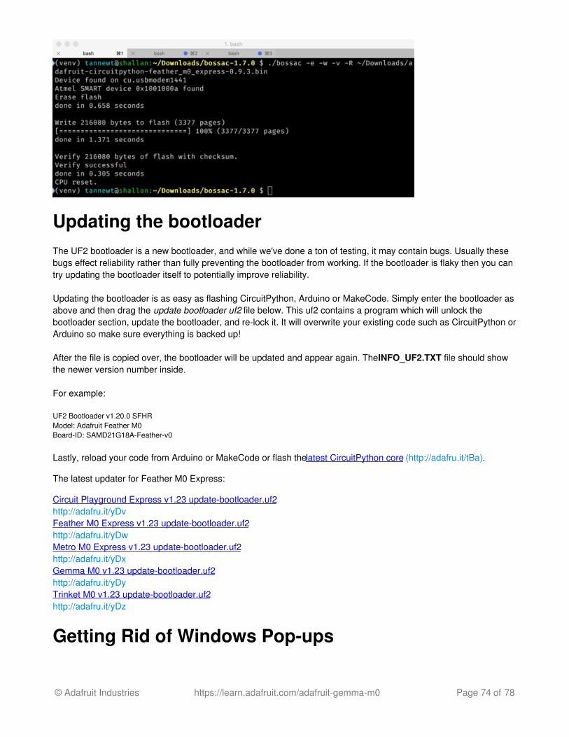
Running bossac on the command line
If you are using the Arduino IDE, this step is not required. But sometimes you want to read/write custom binary files,say for loading CircuitPython or your own code. We recommend using bossac v 1.7.0 (or greater), which has beentested. The Arduino branch is most recommended (http://adafru.it/vQb).
You can download the latest builds here. (http://adafru.it/s1B) The mingw32 version is for Windows, apple-darwin forMac OSX and various linux options for Linux. Once downloaded, extract the files from the zip and open thecommand line to the directory with bossac
For example here's the command line you probably want to run:
bossac -e -w -v -R ~/Downloads/adafruit-circuitpython-feather_m0_express-0.9.3.bin
This will -erase the chip, -write the given file, -verify the write and -Reset the board. After reset, CircuitPython shouldbe running. Express boards may cause a warning of an early eject of a USB drive but just ignore it. Nothingimportant was being written to the drive. A hard power-reset is also recommended after bossac, just in case.
© Adafruit Industries https://learn.adafruit.com/adafruit-gemma-m0 Page 73 of 78
Updating the bootloaderThe UF2 bootloader is a new bootloader, and while we've done a ton of testing, it may contain bugs. Usually thesebugs effect reliability rather than fully preventing the bootloader from working. If the bootloader is flaky then you cantry updating the bootloader itself to potentially improve reliability.
Updating the bootloader is as easy as flashing CircuitPython, Arduino or MakeCode. Simply enter the bootloader asabove and then drag the update bootloader uf2 file below. This uf2 contains a program which will unlock thebootloader section, update the bootloader, and re-lock it. It will overwrite your existing code such as CircuitPython orArduino so make sure everything is backed up!
After the file is copied over, the bootloader will be updated and appear again. The INFO_UF2.TXT file should showthe newer version number inside.
For example:
UF2 Bootloader v1.20.0 SFHRModel: Adafruit Feather M0Board-ID: SAMD21G18A-Feather-v0
Lastly, reload your code from Arduino or MakeCode or flash the latest CircuitPython core (http://adafru.it/tBa).
The latest updater for Feather M0 Express:
Circuit Playground Express v1.23 update-bootloader.uf2http://adafru.it/yDvFeather M0 Express v1.23 update-bootloader.uf2http://adafru.it/yDwMetro M0 Express v1.23 update-bootloader.uf2http://adafru.it/yDxGemma M0 v1.23 update-bootloader.uf2http://adafru.it/yDyTrinket M0 v1.23 update-bootloader.uf2http://adafru.it/yDz
Getting Rid of Windows Pop-ups
© Adafruit Industries https://learn.adafruit.com/adafruit-gemma-m0 Page 74 of 78

If you do a lot of development on Windows with the UF2 bootloader, you may get annoyed by the constant "Hey youinserted a drive what do you want to do" pop-ups.
Go to the Control Panel. Click on the Hardware andSound header
Click on the Autoplay header
Uncheck the box at the top, labeled Use Autoplay for alldevices
Making your own UF2Making your own UF2 is easy! All you need is a .bin file of a program you wish to flash and the Python conversion
© Adafruit Industries https://learn.adafruit.com/adafruit-gemma-m0 Page 75 of 78

script (http://adafru.it/vZb). Make sure that your program was compiled to start at 0x2000 (8k) because thebootloader takes the first 8k. CircuitPython's linker script (http://adafru.it/vZc) is an example on how to do that.
Once you have a .bin file, you simply need to run the Python conversion script over it. Here is an example from thedirectory with uf2conv.py:
uf2conv.py -c -o build-circuitplayground_express/revg.uf2 build-circuitplayground_express/revg.bin
This will produce a revg.uf2 file in the same directory as the source revg.bin. The uf2 can then be flashed in thesame way as above.
© Adafruit Industries https://learn.adafruit.com/adafruit-gemma-m0 Page 76 of 78
Downloads
Files:ATSAMD21 Datasheet (http://adafru.it/xZe)Webpage for the ATSAMD21E18 (main chip used) (http://adafru.it/xZf)EagleCAD files on GitHub (http://adafru.it/xZA)Fritzing object in Adafruit Fritzing library (http://adafru.it/aP3)
Default CircuitPython files included on-chiphttp://adafru.it/yb8
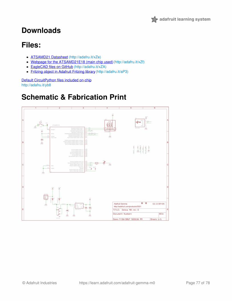
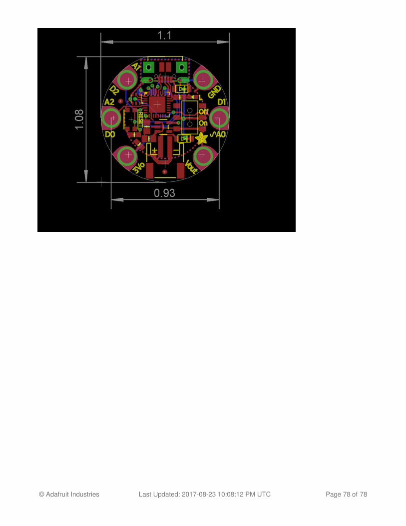
Schematic & Fabrication Print
© Adafruit Industries https://learn.adafruit.com/adafruit-gemma-m0 Page 77 of 78
© Adafruit Industries Last Updated: 2017-08-23 10:08:12 PM UTC Page 78 of 78