
AD-Ai72 096 THE TENSILE AND STRENGTHS … · reportedby__Garfieldin a technique for ......
139
AD-Ai72 096 THE TENSILE AND SHEAR BOND STRENGTHS OFPPOLY (METHYL METHACRYLATE) PROCES..(U) AIR FORCE INST OF TECH I MRIGHT-PRTTERSONAFB OH J E ZURASKY MAY 86 I UNCLASSIFIED AF IT/CI/NR-8 -16 T F/G 11/9 NU.
-
Upload
nguyendieu -
Category
Documents
-
view
214 -
download
0
Transcript of AD-Ai72 096 THE TENSILE AND STRENGTHS … · reportedby__Garfieldin a technique for ......

AD-Ai72 096 THE TENSILE AND SHEAR BOND STRENGTHS OFPPOLY (METHYLMETHACRYLATE) PROCES..(U) AIR FORCE INST OF TECH
I MRIGHT-PRTTERSONAFB OH J E ZURASKY MAY 86
I UNCLASSIFIED AF IT/CI/NR-8 -16 T F/G 11/9 NU.

toii 128 W
1111 h.
MICROCOPY RESOLUTION TEST CHARTNATIONAL BUREAU OF STANDARDS- 1963,A

SECURITY CLASSIFICATION OF THIS PAGE (When DateEntered),REPORT DOCUMENTATION PAGE READ INSTRUCTIONS
RN BEFORE COMPLETING FORM
I. REPORT NUMBER 2. GOVT ACCESSION NO. 3. RECIPIENT'S CATALOG NUMBER: AFIT/CI/NR 86- 160T
4. TITLE (and Subtitle) S. TYPE OF REPORT & PERIOD COVERED
The Tensile and Shear Bond Strengths of THESIS/DA$$VAjQWO Poly (Methyl Methacrylate) Processed on
Ln Electrolytically Etched Ticonium s. PERFORMING O1G. REPORT NUMBER
7. AUTHOR(s) S. CONTRACT OR GRANT NUMBER(&)
N John Edward Zurasky
9. PERFORMING ORGANIZATION NAME AND ADDRESS |0. PROGRAM ELEMENT. PROJECT. TASK
AREA & WORK UNIT NUMBERS
AFIT STUDENT AT: The University of Texas
II. CONTROLLING OFFICE NAME AND ADDRESS 12. REPORT DATE
&\198613. NUMBER OF PAGES
7414. MONITORING AGENCY NAME & ADDRESS(lI different from Controlling Office) IS. SECURITY CLASS. (of ihis report)
UNCLASS
1Sa. DECL ASSI FIC ATION/ DOWN GRADINGSCHEDULE
16. DISTRIBUTION STATEMENT (of thi Report) D T ICAPPROVED FOR PUBLIC RELEASE; DISTRIBUTION UNLIMITED ELECTE
~ SEP2 2~ W617. DISTRIBUTION STATEMENT (of the abstract entered in Block 20, If different from Report) W
B
IS. SUPPLEMENTARY NOTES
APPROVED FOR PUBLIC RELEASE: IAW AFR 190-1 1 E. WOLAVERDean for Research andProfessional DevelopmentAFIT/NR
19. KEY WORDS (Continue on reverse side If necessary and identify by block number)
,m 20. ABSTRACT (Continue on reverse side If neceeary and Identify by block number)L.
ATTACHED ...
DD," F 1473 EDrTION OF I NOV 65 IS OBSOLETE
SECURITY CLASSIFICATION OF THIS PAGE (4ihen Data Entered)
, .. ' .' " -', , :-.. ~ -., , I ..

2
INTRODUCTION
The rtention of acrylic denture resins to metal based dentures and
removable partial dentures has been accomplishedt,ng beads, nail
heads, open ladders, or some other macroscopic retentive design.-3
Such retentive configurations may often encroach upon limited interarch
space. Additionally, the adequacy of retentive strength found with
these methods has been questioned by Dunny and King.4 Yet, Brudvik 5
stated that, when sufficient n size and spacing, retention beads will
provide an acceptable means for acrylic resin retention. Regardless,
gaining the necessary clinical interarch space toiL4a this form of
*retention is not always possible.
.. An alternative to the macroscopic retentive designs has been
reportedby__Garfieldin a technique for relining metal based dentures.
This technique suggests the electrochemical etching of base metals,
normally associated with metal-etched resin-bonded restorations, as a
retentive system for denture acrylic resins.
This form' of microscopic retention may provide an improvement over
the disadvantages of Interarch space and retentive bond strength
reported with macroscopic designs. The retentive strength of composite 'S'
resin materials to electrolytically etched base metals has been
reported. 7 -I While these bond strengths have been high, the retentive
strength of denture acrylic resin to electrochemically etched base
metals has not been investigated. The purpose of thisfnve tior was _
to examine the retentive bond strength of a denture acrylic resin to an
" electrochemically etched base metal in comparison to conventional- "'odes
S DNet Special
nil

AFOMS/SGD, Brooks AFB TX 78235 A OP~ 7 1A'
THE TENSILE AND SHEAR BOND STRENGTHS OF POLY (METHYL
NETHACRYLATE) PROCESSED ON ELECTROLYTICALLY ETCHED TICONIUM
A
THESIS
Presented to the Faculty of
The University of Texas Graduate School of Biomedical Sciences
at San Antonio
in Partial Fullfilluent
of the Requirements
for the Degree of
MASTER OF SCIENCE
By
John Edward Zurasky, B.S., D.D.S.
San Antonio, Texas
May, 1986
U 16 131

Improved adhesion of denture acrylic resins to base metal alloys
John E. Zurasky, D.D.S.*
E. Steven Duke, D..S., M.S.D.**
Wilford Hall USAF Medical Center, San Antonio, Texas
Submitted in partial fulfillment of the requirements for the M.S.D.
degree.
*Senior Prosthodontic Resident
**Chief Restorative Dentistry
(The views expressed herein are those of the authors and do not
necessarily reflect the views of the United States Air Force or the
Department of Defense)

2
INTRODUCTION
The retention of acrylic denture resins to metal based dentures and
removable partial dentures has been accomplished utilizing beads, nail
heads, open ladders, or some other macroscopic retentive design.1- 3
Such retentive configurations may often encroach upon limited interarch
space. Additionally, the adequacy of retentive strength found with
these methods has been questioned by Dunny and King.4 Yet, Brudvik 5
stated that, when sufficient in size and spacing, retention beads will
provide an acceptable means for acrylic resin retention. Regardless,
gaining the necessary clinical interarch space to utilize this form of
retention is not always possible.
An alternative to the macroscopic retentive designs has been
reported by Garfield6 in a technique for relining metal based dentures.
This technique suggests the electrochemical etching of base metals,
normally associated with metal-etched resin-bonded restorations, as a
retentive system for denture acrylic resins.
This form of microscopic retention may provide an improvement over
the disadvantages of interarch space and retentive bond strength
reported with macroscopic designs. The retentive strength of composite
resin materials to electrolytically etched base metals has been
reported. 7- 11 While these bond strengths have been high, the retentive
strength of denture acrylic resin to electrochemically etched base
metals has not been investigated. The purpose of this investigation was
to examine the retentive bond strength of a denture acrylic resin to an
electrochemically etched base metal in comparison to conventional

3
retentive beads.
METHODS AND MATERIALS
Forty nickel-chrome (Ticonium 100, Ticonium Co., Albany, NY)
specimens 1cm square and 1.6mm thick were cast utilizing the
manufacturer's directions for investment, burnout, and casting. Two
groups of metal specimens were prepared: 20 for electrolytic etching and
20 with bead retention.
The specimens for electrolytic etching were recovered after
casting, sandblasted, Ti-Lectro (Ticonium Co., Albany, NY) polished, and
faced with 400 grit silicone carbide abrasive. Prior to etching with a
Time Etch etching machine (Dental Laboratories, Inc., Baltimore, MD),
they were cleaned by air abrading with 50u aluminum oxide and then steam
cleaned. Electrical continuity was tested and the wire attached to the
anode of the etcher with the metal specimens submerged in the acid.
Electrolytic etching was performed using 10% sulfuric acid with a
current density of 300 milliamps for 3 minutes per metal square. An 18%
hydrochloric acid was used in an ultrasonic unit for 10 minutes to clean
the metal surface after etching. They were then rinsed with distilled
water. A stereo microscope at 50X was used to assure that uniform
etching of the specimens had been achieved. Photomicrographs of
representative specimens were made using the Phillips model 505 scanning
electron microscope (Phillips Co., Houston, TX). Figure I shows the
resultant etch.
The bead retention specimens were prepared by placing six Kayon

4
(Kay See Dental Manufacture Co., Kansas City, MO) synthetic resin
retention beads size 14, approximately 1.0mm in diameter, within a 5mm
diameter circle in the center of the metal specimens. The beads were
arranged so that the minimum space between any two beads was twice their
diameter. The bead specimens were recovered after casting, sandblasted,
and Ti-Lectro polished.
To facilitate fabrication of a wax pattern for acrylic resin
processing, a teflon cylinder 3.5cm long was prepared with a 6.35mm
diameter hole in the center. This cylinder was centered on the metal
specimens and filled with melted baseplate wax (Hygenic Corp., Akron,
OH) using a glass eyedropper. To prevent premature solidification of
the wax, the metal specimens were warmed on a glass slab over a water
bath at 200°F. Following sufficient cooling, the wax rod with the
attached metal specimen was ejected from the teflon mold. Figure 2
shows the prepared specimens. Both the etched and the bead specimens
were prepared for acrylic resin processing in this manner.
The specimens were flasked in a conventional upper denture flask
(Hanau Engineering, Buffalo, NY). The flask was inverted and the metal
specimens attached to the cap with a spot of sticky wax. Seven
specimens were positioned around the periphery of the cap. The cope was
placed on the cap and over the entire specimens. Dental stone was mixed
and the cope filled so that the top of the wax rods were even with the
top of the stone. Lastly, the drag was placed in position without the
center plug and filled with dental stone to complete the modified
flasking process.

5
After setting, the flasks were placed in boiling water. The wax
was boiled out and wax solvent was used to remove the residue. Soap was
used to remove any oily film from the wax solvent and the flasks were
allowed to cool. Alcote separating agent (L.D. Caulk Co., Milford, DE)
was painted on the stone surfaces. Lucitone 199 (L.D. Caulk Co.,
Milford, DE) was mixed according to the manufacturer's directions. The
specimens were packed similar to dentures; three trial packs were done
utilizing 3100 psi pressure. The resin was cured for nine hours at
163°F in a Hanau (Hanau Engineering, Buffalo, NY) curing unit. The
specimens were recovered, shell blasted, and stored in distilled water
at 2U0 C for 17 days prior to bond testing. Figure 3 shows the completed
specimens.
Tensile bond strengths of the specimens were determined using the
Instron Universal Testing Machine (Instron Corp., Canton, MA) with a 50
kilonewton load cell. The metal tabs were positioned in a holding
device on the upper arm of the Instron, and self aligning "V"-grips were
used to grasp the acrylic resin rod from the lower arm (Figure 4).
The chart paper speed was set at 50mm/mmn with a 1000 newton full
scale. The crosshead speed for the Instron was set at 5mm/min. The
force in newtons required to separate the acrylic resin rods from the
metal specimens was recorded as the tensile bond strength.
A Scanning Electron Microscope was used to evaluate the fracture
site of the etched and the bead specimens. Representative specimens for
the two retentive techniques were examined and evaluated as to their
fracture mode.
- .'% E V.-i-f a

6
The resulting tensile bond strengths were subjected to a Students'
T-test to determine if significant differences in bond strengths were
observed.
RESULTS
The results of the tensile bond strengths for the etched and the
bead specimens are shown in Table 1. The mean tensile bond strength for
the etched specimens was 472.5 newtons (16.70 MPa) with a standard
deviation of 130.1 (4.60 MPa). The mean tensile bond strength for the
bead specimens was 134.9 newtons (4.77 MPa) with a standard deviation of
75.7 (2.68 MPa).
Statistical analysis using the Students' T-test revealed that the
tensile etched bond strengths were significantly (p < 0.001) higher than
the tensile bead strengths.
Examination of the fracture sites using the scanning electron
microscope demonstrated that a cohesive failure occurred commonly in the
poly methyl methacrylate leaving acrylic resin fragments mechanically
locked into the etched metal specimens (Figure 5). At times metal
particles were also observed imbedded in the fractured acrylic resin
surfaces.
Examination of the bead specimens showed that an adhesive failure
occurred between the acrylic resin and the beads. Extensive plastic
deformation of the poly methyl methacrylate was evident (Figure 6).

7
DISCUSSION
Fabrication and preparation of the test specimens were accomplished
utilizing laboratory methods that are commonly used for clinical
prostheses. These same laboratory procedures would be used for clinical
application of the results of this study.
The poly methyl methacrylate rod was waxed-up directly on the
etched surface of the metal. The etched surface was fully contaminated
with wax, wax solvent and soap, then flushed with clean boiling water
and allowed to dry before the acrylic resin was split-packed.
The effect of any manipulation or contamination of the etched metal
surface has not been studied in depth. It has been reported by
McLaughlin 7 ,6,12 and Thompson and Livaditis i I that the etched surface of
the metal must be maintained contamination free to preserve the bonding
capability. This study gives indications that manipulation and
contamination may not be as critical as was originally thought. Some
consideration must be given to the packing conditions of 3000 psi
applied pressure which cannot be directly compared to resins placed
intraorally. Meiers et al. 13 looked at a variety of surface treatments
on the bond strength of etched metal retainers. They found that
abrasion with salivary contamination did not decrease the shear bond
strength, and that the etched metal surface may not be as fragile as is
thought. It is evident that further research is necessary in this area.
It should be emphasized that controlling the etching conditions is
one of the most important factors in consistent etching.8 ,1 2 ,14 - 19
Using controlled times and currents with precisely measured acids, one

8
can expect to routinely obtain retentive etch patterns.
It is apparent that a very strong mechanical bond is available
between the etched metal base or removable partial denture framework and
the acrylic resin. The clinical applicability of these findings can be
utilized on a base metal prosthesis where retention of acrylic resin is
necessary. This retention capability can salvage an ill-fitting metal
based denture by allowing a reline of the intaglio surface. The acrylic
resin will bond to the metal over the entire etched surface area.
Acrylic resin retention has always oeen a problem where interarch
space is minimal. Microscopic etcned retention preserves the maximum
remaining space for placement of artificial teeth.
CONCLUSIONS
The following results of this study show that the tensile bond
4 strength using electrochemical etching to obtain microscopic retention
of the poly methyl methacrylate is significantly greater than the
acceptable bead retention:
I. The etched tensile bond is nearly 3.5 times the strength of the
bond with beads.
2. The tensile fracture for the etched specimens was one of a
cohesive failure of the acrylic resin. The bead specimens
failed adhesively at the resin-metal interface.

9
Table 1. Tensile Bond Strengths of Etched and Bead Specimens
Technique N Mean Bond S.D.
Etched 20 16.70 MPa 4.60 MPa
Beads 20 4.77 MPa 2.68 MPa
P < 0.001

10
REFERENCES
1. Morrow, R.M., K.D. Rudd, and H.F. Eissman: Dental Laboratory
Procedures Removable Partial Dentures, Volume 3. St. Louis, 1980,
The C.V. Mosby Company, pp 234-249.
2. Henderson, D. and V.L. Steffel: McCracken's Removable Partial
Prosthodontics. St. Louis, 1973, The C.V. Mosby Company,
pp 343-352.
3. Boucher, L.J. and R.P. Renner: Treatment of Partially Edentulous
Patients. St. Louis, 1982, The C.V. Mosby Company, pp 52-55.
4. Dunny, J.A. and G.E. King: Minor connector designs for anterior
acrylic resin bases: a preliminary study. J Prosthet Dent
34:496, 1975.
5. Brudvik, J.S.: Dental Laboratory Procedures Complete Dentures,
Volume I.. St. Louis, 1980, The C.V. Mosby Company, p 457.
6. Garfield, R.E: An effective method for relining metal-based
prostheses with acid-etch techniques. J Prosthet Dent 51:719,
1984.
7. McLaughlin, G. and D. Foerth: Composite bonding of etched metal
bridges. Gen Dent 30:132, 1982.
8. McLaughlin, G: One hundred second etch technique for etched-metal
bridges. J Mich Dent Assoc 64:347, 1982.
-wi- ll I

11
9. Livaditis, G.J. and V.P. Thompson: Etched castings: an improved
mechanism for resin-bonded retainers. J Prosthet Dent 47:52,
1982.
10. Thompson, V.P., G.J. Livaditis, and E. DelCastillo: Resin bond to
electrolytically etched non-precious alloys. IADR Program and
Abstracts, No. 265, p 377, 1981.
11. Thompson, V.P. and G.J. Livaditis: Etched casting acid etch
composite bonded posterior bridges. Pediatr Dent 4:38, 1982.
12. McLaughlin, G.: Composite bonding of etched metal anterior splint.
Compendium Cont Ed in Dent 2:279, 1981.
13. Meiers, J.C., M.E. Jensen, and T. Mayclin: Effect of surface
treatments on the bond strength of etched-metal resin-bonded
retainers. J Prosthet Dent 55:185, 1985.
14. Simonsen, E.W., V. Thompson, and G. Barrack: Etched Cast
Restorations: Clinical and Laboratory Techniques. Chicago, 1983,
Quintessence Publishing Company, pp 42-44.
15. Thompson, V.P.: Electrolyte etching modes of various NP alloys for
resin bonding. IADR Program and Abstracts, No. 65, 1982.
16. Thompson, V.P., K. Grolman, and R. Liao: Electrolytic etching of
Co-Cr alloys for resin bonded restorations. J Dent Res, 63:324,
1984.
17. Jensson, J.S., K.F. Leinfelder, and J.E. Lemons: Ag-Pd alloys for
resin-bonded retainers. J Dent Res, 64:297, 1985.
*.t361%M Mm
12
18. Al-Shamary, A., J. Meiers, T. Mayclin, and M. Jensen: Bond
strengths of etched metal to enamel: effects of different etching
times. J Dent Res, 62:221, 1983.
19. Sloan, K.M., R.E. Lorey, and G.E. Myers: Evaluation of laboratory
etching of cast metal resin bonded retainers. J Dent Res, 62:305,
1983.

13
LEGEND SHEET
Figure 1. Photomicrograph of electrolytically etched nickel-chrome
alloy (2UOX).
Figure 2. Wax rods on metal specimens being prepared for acrylic resin
processing.
Figure 3. Specimens as prepared for tensile bond testing.
Figure 4. Specimen in place in upper holding device and lower
"V" grips of the Instron Machine.
Figure 5a. Tensile fractured etched specimen: lower one-third of
photomicrograph shows the etched metal surface outside of
the acrylic resin rod. Upper two-thirds shows acrylic
resin retained in the etch (45X).
Figure 5b. Fractured specimen showing cohesive failure with large block
of acrylic resin remaining attached to the etched metal
(50X).
Figure b. Adhesive failure and plastic deformation of the acrylic
resin retained by beads.

14
ADDRESS OF AUTHOR
DR. JOHN E. ZURASKY
6302 Gallery Cliff
San Antonio, Texas 78249
Note: Address will change as of I August 1986, if this article is
accepted for publication, the Journal will be notified.
Jil

15
TRANSFER OF COPYRIGHT OWNERSHIP
This article, Improved adhesion of denture acrylic resin to base metal
alloys, submitted to the C.V. Mosby Company for publication, fits the
description in the new U.S. Copyright Act of a "United States Government
work." It was written as a part of our official duties as Government
employees. This means it cannot be copyrighted. The Wilford Hall USAF
Medical Center Legal Counsel has advised us that we do not have any
rights to assign. The article is freely available to you for
publication without a copyright notice, and there are no restrictions on
its use, now or subsequently.
The undersigned author warrants that the article is original, is not
under consideration by another journal, and has not been previously
published. I sign for and accept responsibility for releasing this
material on behalf of any and all co-authors.
John E. Zurasky, D.D.S.

Al )OF1a~rw -

r~ RIP-
-- -.--
r

-. I A
III NE I~ II

ffMi
----. ~--.-- -* - p -
* --- ~ -~-*. *Nill -
KV' 41
d & Ja I ~ .,.. 4. ~ ~a ~ V-' lilt
Mi 4% -'Oft ~ All
- 4%b
*..%-C&g..
p 4~qpw
., -.- , AV
-~s IA---
,q AS '-.- -- -
1w= -~.q-

THE TENSILE AND SHEAR BOND STRENGTHS OF POLY (METHYL
METHACRYLATE) PROCESSED ON .LG+W ETCHED TICONIUM
John Edward Zurasky
APPROVED:
Su ing Profes or-
A",
Date
APPROVED:
V er . Mlie- f~ .D

DEDICATION
I dedicate this thesis to my wife, Nancy, and to my
son, Jacob. It was with their patience, understanding, and
support that I was able to attain this goal.
I also dedicate this thesis to my parents, John and
Elizabeth Zurasky. From my earliest memories they taught me
that "good enough" was not the answer. To attain the
unattainable goals one must do the "best" he can do with no
regrets.
I am thankful for the way I was raised and for the
motivation my family instilled in me. To you I dedicate
this thesis.
iii

ACKNOWLEDGEMENTS
I would like to thank Dr. E. Steven Duke (Chief,
Dental Materials, Director of Research, Wilford Hall Medical
Center) for his guidance as my supervising professor. Also,
to Dr. Thomas L. Huff (Past Chairman Department of
Prosthodontics, Wilford Hall Medical Center) my thanks for
his direction of my Prosthodontic training.
I would like to recognize the other members of my
supervising committee; Dr. Earl Feldmann (Professor and
Chairman of Prosthodontics, UTHSC/SA), Dr. Robert Morrow
(Professor and Head, Division of Postdoctoral Prosthodontics
and Associate Dean for Advanced Education, UTHSC/SA) and Dr.
Barry Norling (Head, Division of Biomaterials, UTHSC/SA).
I thank the United States Air Force and Wilford Hall
Medical Center for providing the opportunity and materials
needed for this research.
A special thanks to Mr. Robert (Mac) McConnell, C.D.T.
for his many hours helping me design and test this research.
Also special thanks to my wife, Nancy, for her typing and
word processing.
iv

THE TENSILE AND SHEAR BOND STRENGTHS OF POLY (METHYL
METHACRYLATE) PROCESSED ON ELECTROLYTICALLY ETCHED TICONIUM
JOHN EDWARD ZURASKY, M.S.
The University of Texas Graduate School of Biomedical Sciences
at San Antonio
Supervising Professor: E. Steven Duke D.D.S., M.S.D.
The electrochemical etching of dental alloys has been
incorporated into numerous restorative techniques. The
bonding of resin materials to etched alloys is reported with
acid etched retainers, resin veneers, and proposed for
relining metal based dentures.
The difficulty in relining metal based dentures has
been a primary disadvantage associated with their use. The
ability to retain denture acrylic resins by electrochemical
V

etching may facilitate relining procedures. Additionally,
an improvement in acrylic resin retention may be found over
conventional retention techniques.
The purpose of this research is to examine the bond of
poly (methyl methacrylate) to electrolytically etched
Ticonium and to quantitatively measure the tensile and shear
bond strengths in comparison to the accepted retention of
poly (methyl methacrylate) to Ticonium with beads.
Eighty nickel-chrome alloy (Ticonium 100) specimens,
one centimeter square and 1.6 millimeters thick were cast.
Forty specimens were prepared with bead retention and the
other 40 were electrolytically etched. A rod of poly
(methyl methacrylate) 3cm long and 6.35mm in diameter was
processed onto the Ticonium specimens using the conventional
pressure pack, heat cure technique.
An Instron Universal Testing Machine was used to
quanitatively measure the tensile and shear bond strengths.
A scanning electron microscope was used to examine
representative electrolytically etched Ticonium specimens
and to evaluate the fracture site.
The tensile bond strengths were significantly higher
(p < .001) for the electrolytically etched specimens as
compared to the specimens with beads. The more commonly
used shear bond testing for evaluating resin bond strength
to etched metals was found inappropriate in this study, due
to the high plastic behavior of the acrylic resin under
load.
Vi

TABLE OF CONTENTS
Page
Approval .*...................................... ii
Dedication . .. .. ... .. . .. .. ... * .. ....... **.* **** iii
Acknowledgements .............. ............... iv
Abstract ........ 0 ......... ... *..... ... *.... v
Table of Contents ................... vii
List of Figures...................... . . .. . . .. . ..
II . LITERATURE REVIEW .. .. . .. .. .. .. .. . .. * .. . .. .. 3
A.* Acid Etching ........ * ... 0 ... 3
B. Methyl Methacrylate ..............6-6.... 7
C. Metal Based Dentures ... *......*......... 9
D. Acrylic Resin Retention ................ 1.4
E . Summary . .. . . .. .................. ******15
F. Problem Statement .................... 16
III. RESEARCH OBJECTIVES ........................ 17
IV. METHODS AND MATERIALS ................... 18
A. Preparation of the Ticonium Specimens ... 18
B. Electrolytic Etching ................ 18
C.* Bead Retention ............ *.......*.... 21
D. Poly (Methyl Methacrylate) Processing .. 26
E. Tensile Strength Determination .......... 30
Vii

F. Shear Strength Determination ............ 33
G. Evaluation of Fracture Sites ........... 33
HI. Statisical Analysis ....... *............. 39
V.* RESULTS .*... -o....o 40
VII. SUMMARY .. .. . . .. .. . .. o . .. .. .*..a ............ * * 56
Appendicies ........... ........ *...... ...... 59
Appendix A: Raw Data Tensile Bond Strengths. 60
Appendix B: Raw Data Shear Bond Strengths .. 62
Appendix C: Manufactures and Materials ..... 64
Appendix D: Technical References ........ 65
Literature Cited ..... 0 ............ 66
Vita ...................... ................. 75
Viii
46r '' a k&J - ,a ..

List of Tables
Page
Table 1. Tensile Bond Strengths for the Etched
and Bead Specimens ......................... 41
Table 2 Shear Bond Strengths for the Etched and
Bead Specimens *........................ 46
Table 3 Summary Table Comparing the Etched to
Bead Tensile Bond Strengths................ 57
ix

List of Figures
Page
Figure lA Horizontal View of Sprued Patterns ..... 19
IB Vertical View of Plastic Patterns Prior
t o C a st ing . . . . . . *. 0. *. * . * * * * & . . . . . . . .* * * . 2 0
Figure 2 Time Etch Etching Machine ................. 22
Figure 3 Photomicrograph at 50X Shoving the
Representative Etch for Ticonium .......... 23
Figure 4A Scanning Photomicrograph of the Etched
Metal Surface at 200X ..................... 24
4B Photomicrograph at 1000X of the Etched
Surface on the Metal Specimen ............. 25
Figure 5 Representative Bead Specimen Showing the
Arrangement of the Beads .................... 27
Figure 6A Vertical View of the Teflon Cylinder
Used In the Preparation of the Wax
Patterns *...... 9.... *.... * ............ 28
6B Teflon Cylinder with Metal Specimen
C entered in Place ..... #.4000....... *4...... 29
figure 7 Specimens Positioned Around the Periphery
of the Cap for Fasking ................... o 31
Figure 8 Completed Specimens Ready for Bond
Strength Determination .. oo.......... .... 32
X

LIST OF FIGURES CONTINUED
Page
Figure 9A Specimen in Upper Holding Device 'or
the Instron Machine ...................... 34
9B Specimen In Place for Tensile Bond
Evaluation. Self-Aligning "V"-Grips
Are Holding the Acrylic Resin Rod ......... 35
Figure 10A Specimen Positioned in Holding Device
for Shear Bond Evaluation with Shearing
Blade ........ ........... . 36
10B Specimen in Instron Machine Ready for
Shear Bond Determination ................. 37
Figure 11 Specimen Mounted for Examination in the
Scanning Electron Microscope ............. 38
Figure 12 Cohesive Failure of the Acrylic Resin
With the Etched Metal Specimen at 50X ..... 42
Figure 13 Acrylic Resin Retained in the Etch.
Note Difference (Arrcw) Between the Area
of Acrylic Resin Attachment and the
Surrounding Etched Metal Surface 45X...... 43
Figure 14A Adhesive Failure and Plastic Deformation
of the Acrylic Resin on Beads ............ 44
14B Adhesive Failure of Acrylic Resin on Beads.45
xi

LIST OF FIGURES CONTINUED
Page
Figure 15A Acrylic Resin Adhering to the Etched
Metal Surface After Shear Failure 250X ... 48
15B Cohesive Shear Failure of the Acrylic
Resin on an Etched Specimen at 2000X ..... 49
Figure 16 Surface of the Acrylic Resin Rod After
Shear Failure From the Etched Surface
at 20X ................................... 50
Figure 17 Severe Plastic Deformation of the Acrylic
Resin Sheared from a Bead Specimen
at 20K. Note the Deformation Due to
the Shearing Blade ....................... 51
Figure 18 Metal Bead Specimen with the Loss
of Two Beads Due to Contact with
the Shearing Blade 15X ................... 52
xii
-I

I. INTRODUCTION
To date, macroscopic retention has been used for the
attachment of denture acrylic resins to metal frameworks.
This mechanical retention, be it nailheads, beads, open
ladder, or spurs, requires significant space, either
interarch space or on the tissue surface of a metal based
denture that needs relining. In fact, this is one of the
reasons metal based dentures are not used more often, even
though they have some advantages over acrylic resin bases.
The electrolytic etching of alloys has been shown to be
of significant value in dentistry for the purpose of bonding
resin based materials. This technique may allow for
sufficient retention of denture acrylic resin to metal based
dentures and removable partial denture frameworks to make
relines feasible and improve framework design.
Metal electrolytic etching offers a new approach to
obtain retention of denture acrylic resin to metal. This
retention method would be the mechanical interlocking of
acrylic resin molecules into the microscopic undercuts in
the metal surface of denture frameworks in place of
conventional retention methods that require significant
space. Limited interarch space could be preserved for
placement of teeth and metal based dentures could be relined
with ease.
Metal based dentures have many advantages but up to
now, a major disadvantage has limited their use. This~1

2
problem has been caused by the difficulty, almost
impossibility, to adequately and economically reline them.
Using etching of the metal base as the retention mechanism
for the denture acrylic resin, refitting can now be
simplified.
This form of microscopic retention may be an
improvement over the macroscopic retention designs. All the
remaining interarch space can be used for placement of
artifical teeth and the bond strength may be higher due the
interlocking along the entire etched surface area. The
retentive strengths of composite resin materials to
electrolytically etched base metals have been reported.
While these bond strengths have been high, the retentive
strength of denture acrylic resin to electrolytically etched
base metals has not been investigated. The poly (methyl
methacrylate)-etched metal bond needs to be evaluated and
quantified.
This reasearch examines the mechanical bonding of
denture acrylic resin to electrolytically etched Ticonium
(Ticonium Co, Albany, N.Y.) utilizing tensile and shear bond
strengths measured on an Instron Universal Testing Machine
(Instron Corp., Canton, Mass.) and comparing the results to
the bond strength of Ticonium with bead retention.
&k

III. LITERATURE REVIEW
A. Acid Etching
Buonocore (1955) studied the effect of acid treatment
on enamel for the purpose of increasing adherence of
restorative materials. He found that by treating enamel
with phosphoric acid, there was a significant increase in
the surface area and the surface wettability for more
intimate contact between the acrylic resin and enamel
thereby increasing adhesion.
Rochette (1973) described the attachment of a splint to
enamel by using a gold framework with undercut perforations
bonded to acid etched enamel. He is given credit for
introducing the acid-etch metal retainers to dentistry.
Since then many authors including: Stuart (1974), Stolpa
(1975), Lambert et al.(1976), Kochavi et al.(1977),
Jenkins (1978), Reinhardt et al.(1979), Sweeney et al.
(1980), Esposito (1981), Yanover et al.(1982), and Hamada et
al.(1985), have contributed articles on this subject.
Howe and Denehy (1977) used a technique of acid etching
enamel and bonding with a composite resin for replacement of
a missing anterior tooth. A ceramo-metal nonprecious
framework was constructed with retentive holes for the
resin. Jordon et al.(1978) evaluated 86 temporary fixed
partial dentures of the acid-etch resin technique. The acid
etching produces microporosities up to 50 microns deep that
3

4
fill with the resin resulting in an interlocking action of
the resin projections in the microporosities.
Nathanson and Momn (1980.) modified Howe and Denehy's
(1977) design using rectangular perforated metal pads used
in orthodontics instead of a cast framework. This has the
advantage of being a one appointment technique.
Livaditis (1980) described cast resin-bonded retainers
for posterior teeth, including design, fabrication, and
bonding. He feels that these retainers are an alternative
to the accepted fixed retainer.
Williams et al.(1982) studied retainer design and found
that most retainer failures occurred at the retainer -
composite resin interface. With greater occlusal forces
being placed on these restorations, failures were more
common at the composite-metal interface than the enamel-
composite area. Progress necessitated a stronger bond to
the metal.
Dunn and Reisbick (1976) described and used an
electrochemical etching of Vitallium to obtain a mechanical
bond of ceramic coatings. They found that complex geometric
patterns on the surface of the metal increased the surface
area and the retention sites. Tanaka et al.(1979) developed
a technique for retention of resin veneers on complete
crowns by using a pitting corrosion of the nickel-chromium
copper alloy.
McLaughlin (1981) wrote of the etched metal retainer.
The metal framework was electrolytically etched using
.p.6

5
sulfuric acid and then cleaned using hydrochloric acid to
remove the surface layer of impurities. The etched surface
was found to be microscopically roughened thereby providing
mechanically retentive locks for the resin. He specified
that the etch must not be contaminated and that
contamination would occur if the wax protecting the
nonetched areas was boiled off. McLaughlin (1982) stated
that the composite-metal bond using metal etching is two
times as strong as the enamel-composite bond. He again
cautioned that the etched metal surface is fragile and must
be protected from contamination. The etched surface should
not be touched as even the oil from the fingers will disturb
the bonding capability.
Livaditis and Thompson (1982) found the tensile bond
strength of resin to enamel to be 8.5 - 9.9 MPa (1200-1400
psi), the cohesive bond of the composite resin, 33 - 60 MPa
(4800-8700 psi), and the resin to etched metal 27.3 MPa
(3960 psi). Thompson and Livaditis (1982) found similar
bond strengths and stated that the weakest bond is now that
of resin to enamel. They also stated that contamination of
the etched surface must be avoided. McLaughlin and Foerth
(1982) found that by electrolytically etching the metal,
the entire surface becomes microscopically retentive.
Simonsen et al.(1983) described the electrolytic
etching process. A low voltage direct current is passed
through the electrolytic solution by way of a stainless
steel cathode. The metal casting functions as the anode.
%%.
.' AC

6
A specific current density and time are used to obtain a
controlled etch. The casting is then cleaned with acid in
an ultrasonic unit.
McLaughlin (1982) described a one-step etching process
with the benefit of reduced etching time by mixing acids and
etching in an ultrasonic unit. A follow-up article by
McLaughlin and Masek (1985) compared bond strengths using
the one and two-step etching. They found no significant
difference between the etch systems.
This electrolyically etched retention has been shown to
produce very high bond strengths with composite resin
(Thompson et al. 1981 and Dhillon et al. 1983). The bond
strength is reported to be dependent on a number of
variables including: the type of metal alloy, the specific
etching conditions; type of acid, time, and current, and the
surface area to be etched. Thompson (1982) worked out the
best etching conditions for a variety of non-precious
alloys. Thompson et al.(1984) and Jensson et al.(1985)
studied other alloys for etch capability. Del Castillo and
Thompson (1982) investigated some laboratory variables with
respect to resulting bond strengths. Al-Shammary et
al.(1983) studied the effect of etching times upon the bond
strength. Sloan et al.(1983) examined the bond strength of
resin to etched metal specimens provided from different
laboratories. They found that the quality of etch and the
bond strength varies greatly from one lab to another.
Meiers et al.(1 983) studied the effect of surface
5-V
7
abrasion and salivary contamination on the etched metals and
found no significant decrease in resin bond strength.
Garfield (1984) described a technique for relining
metal based dentures using metal acid etching. He claimed
that the acid etching will cause an adherence of the acrylic
resin to the metal base using routine laboratory reline
procedures. He did not present any data to substantiate
this claim.
B. Methyl Methacrylate
Acrylic resin has been in use for denture bases since
1937, and has become the material of choice (Vernon and
Vernon, 1941). Pryor (1943) stated at that time, methyl
methacrylate was the best all around plastic for dentures
available to the profession. Woelfel (1971) estimated that
more than 95% of all complete denture bases were constructed
of methyl methacrylate polymers or copolymers. Sweeney et
al.(1942) wrote of the dimensional problems with acrylic
resins; the shrinkage during processing, and the expansion
which occurs as a result of water absorption. Further
studies by Skinner and Cooper (1943), Smith (1961, 1962),
Chevitarese et al.(1962), and FitzRoy et al.(1963) evaluated
the dimensional changes of denture acrylic resins.
Brauer (1966) and Voger (1974) described the
composition and reaction of methyl methacrylate. It is the
product of acetone combining with hydrogen cyanide in the
presence of methyl alcohol and sulfuric acid. The monomer,

8
methyl methacrylate, is supplied as a liquid with an
inhibitor, usually hydroquinone, and a crosslinking agent
such as ethylene dimethacrylate. When combined with the
polymer powder, which contains benzoyl peroxide as an
initator, the reaction forms the acrylic resin, poly(methyl
methacrylate). Stafford et al.(1982) wrote that the
strength of poly (methyl methacrylate) should be suspect due
to three-quarters of a million dentures repairs costing
nearly $750,000 annualy as reported by the National Health
Service of England and Wales. Kelly (1969) stated that
fracture of the denture is very common and occurs mostly as
fatigue failure caused by repeated flexure. Johnson et al.
(1981) confirmed this and modified the flexure fatigue
testing to a two-way test for accurate measurement. Cornell
et al.(1960) found that crosslinking the monomer with 10-20%
ethylene dimethacrylate notably improved the impact
resistance.
Tensile strength has been suggested to be one of the
important properties that directly affects clinical
fracture. Matthews and Wain (1956) showed that fracture of
the denture base was the result of tensile failure of the
material. Smith (1961) stated that the pigmentation in poly
(methyl methacrylate) decreased tensile strength due to the
introduction of flaws in the material.
Smith (1961) and Stafford and Smith (1968) found a
reduction in tensile strength after water absorption. They
4attributed this lower tensile strength to the plasticizing
stegt o pls.czn

9
action of the water. Cornell et al.(1960) showed a decrease
in impact strength when acrylic resin samples were stored in
water. Stafford and Braden (1968), Hargreaves (1978), and
Baraby and Braden (1979) studied the water sorption
properties and the effect on the acrylic resin. Peyton and
Mann (1942), and Skinner and Cooper (1943) showed that water
absorption partially compensated for the shrinkage during
polymerization. Braden (1964) found that maximum water
absorption for an average denture may required up to 17 days
at room temperature, depending on the thickness of the
acrylic resin and the diffusion coefficient. He also found
that at oral temperature the water absorption was two times
faster. Brauer and Sweeney (1955) found that water
absorption and molecular weight of the polymer related
inversely. As the molecular weight was increased, the water
absorption decreased. The ADA Specification No. 12 states,
"the increase in weight of the polymer shall not be more
than 0.7 mg/cm sq. of surface after immersion in water for
24 hours at 37.1 degrees C".
C. Metal Based Dentures
Metal based dentures were swaged until Taggart
developed a casting process (Pryor, 1928). Dootz (1980)
described the procedures for fabrication of non-precious
metal base dentures. The laboratory phases are described in
detail from duplication of the master cast to finishing of
the casting.

10
Faber (1957) listed the advantages of a cast metal base
denture including:
1. Less lateral deformation in function
2. Better thermal conduction
3. Less tissue change
4. Less porosity, less resorption
5. More accurate
6. Patients master the use of dentures faster
7. Treatment of poor ridges seem more successful
8. Attains a snugness of fit.
Moore (1967) also listed these advantages of metal
based dentures and stated that their combination aid in the
maintenance of the health of the denture supporting
tissues.
A review of some of the above points citing
investigations by various authors will be discussed.
1. Less lateral deformation in function - Regli and
Kydd (1953) and Regli and Gaskill (1954) showed that
deformation during mastication was 8.5 times less with
metal base dentures than those constructed with acrylic
resin. They found that the mandibular acrylic resin
denture may deform up to five millimeters during
function. Lambretch and Kydd (1962) also found
deformation of the maxillary acrylic resin denture
causing it to move one and a half millimeters away from
the palate. Sweeney (1958) stated that acrylic resin
has been the most accepted denture base material since

its introduction in 1937. One reported problem is the
low fatigue strength which can lead to breakage. Kelly
(1967) stated that flexure fatigue is the chief cause of
failure with poly (methyl methacrylate). He stated that
a solution to problem cases is the metal base. Smith
(1961) suggested that flexing during mastication can
lead to fatigue failure. Johnson and Mathews (1949)
estimated that complete dentures flex about 500,000
times a year. Kelly (1969) showed that the frenum
notch, debris, impurities, or scratches can act as
stress concentrators leading to flexure fatigue.
2. Metal is a better thermal conductor than acrylic
resin - Campbell (1935, 1936) felt that an aluminum
based denture was best because the thermal conduction
allowed stimulation of oral tissues and helped to
maintain tissue health. On the other hand, Kapur and
Fischer (1981) found that increased palatal tissue
temperatures under metal bases interfered with the
gustatory response to taste more than acrylic resin
bases.
3. Less tissue change will occur - Barsoum, Eder, and Asgar
(1968) stated that because a better fit could be
obtained, the metal based denture would be less
irritating to the tissue. Woelfel and Paffenbarger
(1959) showed that 0.5mm shrinkage across the palate
still resulted in a clinically acceptable fit. They
stated that the tissue adapts to the gradual

12
distortional changes.
4. Less porosity with a metal base resulting in less
resorption - Lang (1974) stated that the potential for
plaque adherence causing tissue irritation and
inflammation was less with a metal base.
5. The metal base is more accurate - Lundquist (1963)
showed that due to the taper of the ridges, there was an
average discrepancy of 0.02 inch for heat-cured resin
bases as compared to 0.0015 inch for an aluminum casting
in the palatal area. Woelfel and Paffenbarger (1960)
found dimensional changes of 0.02-0.22Z and Mowery et
al.(1958) found up to 0.2mm dimensional change with no
significant effect on fit of the denture. Yet, Anthony
and Peyton (1962) found that a cast chrome-cobalt alloy
had only the same accuracy of fit as the best heat-cured
dentures. Also, Woelfel and Paffenbarger (1961) stated
that a metal base will not necessarily fit the cast
better than acrylic resin base.
Many investigators studied the self-curing resins
with the hope of obtaining a better fit. Caul et
al.(1952), Mirza (1961), Shepard (1968), Kraut (1971),
and Winkler (1972) found that the final product was as
good as heat-cured dentures. Civjan et al.(1972) and
Weaver and Ryge (1971) stated that their findings
indicated clinically acceptable results using self-
curing resins with the benefit of considerable time
savings.
--. ~*NMI&,l,'~ .*~

13
Grunewald (1964) felt that gold was the metal of choice
for metal based dentures. His study showed that the average
weight loss through extractions and resorption on the
mandible was 29 dwt and 23 grains. To replace this, the
metal base needed to weigh between 14 and 16 dwt. He
thought that this weight was necessary for normal muscle
function and to maintain vertical dimension. Lang (1974)
also described the use of gold in the mandibular denture to
satisfy the advantages previously listed.
The use of aluminum denture bases was favored by
Sizeland-Coe (1951), Campbell (1953, 1954), Lundquist
(1963), Barsoum et al.(1968), and Swartz (1966). Swartz
(1966) found that aluminum bases were the most resistant to
vertical dislodgement. White et al.(1985) found that
anodized aluminum resisted corrosion better than
nonanodized. Tregarthen (1949) also recommended anodizing
to increase corrosion resistance.
Defurio and Gehl (1970) examined retention of maxillary
dentures with respect to the type of base. Aluminum, chrome-
cobalt, gold, and acrylic resin bases were compared. They
found that the chrome-cobalt resisted vertical displacement
the most, followed by aluminum, acrylic resin, then gold.
Swartz (1966) showed that an aluminum base had the best
retention and had better wettability than acrylic resin.
Halperin (1980) recommended long term clinical follow-up
studies to evaluate the aluminum based dentures.
Metal based dentures have very few reported

14
disadvantages. They are contraindicated for patients that
have severe undercuts or are hypersensitive to specific
metals. The greatest disadvantage is the difficulty in
refitting or relining. This has limited their use to the
very mature, well healed ridges (Lang 1974).
Brauer et al.(1959), Shaffer and Filler (1971), and
Christensen (1971) wrote on relining techniques in general.
Lang (1974) stated that the problem with gold based dentures
is that they cannot be relined. Grunewald (1964)
recommended a satisfactory reline by cutting back the gold
base to allow one millimeter of acrylic resin thickness.
There would be no bond of the resin to the base. Faber
(1957) listed the cost and the difficulty of refitting as
disadvantages of metal bases. Sherman and Komorech (1985)
presented a technique for refitting a metal based denture.
Their technique involved removing one millimeter of metal
from the tissue surface then refabrication of a new metal
base to be processed onto the existing teeth.
D. Acrylic Resin Retention
Acrylic resin retention to metal bases or metal
frameworks has been only minimally addressed in the
literature. Dunny and King (1975) looked at different
retention designs with respect to retention strength of
acrylic resin to metal frameworks. They found that beads or
nailheads do not provide strong attachment of the resin to
the framework. Bulk of resin for strength was the most
I.

15
important factor. Brudvik in Morrow, Rudd, and Eissman's
Dental Laboratory Procedures, (1980), stated that retentive
beads, size 14, placed so that there is space between them
equal to twice their diameter will provide excellent acrylic
resin retention.
E. Summary
Electrolytically etched retention of denture acrylic
resin may provide an improvement over the disadvantages of
inadequate interarch space and retentive bond strength
reported with macroscopic designs. The retentive strength
of composite resin materials to electrolytically etched base
metals has been reported. While these bond strengths have
been high, the retentive strength of denture acrylic resin
to electrolytically etched base metals has not been
investigated. The use of metal base dentures could be
facilitated if a bond between the acrylic resin and the
metal was attained and a better technique developed for
relining when necessary. With the advent of metal etching,
this may now be possible.
The purpose of this research is to quantify the bond
between poly (methyl methacrylate) and electrolytically
etched Ticonium by measuring the tensile and shear bond
trengths. A comparison with bead retention will be used to
give clinical relevance.
= ~

16
F. Problem Statement
The difficulty in relining metal based dentures with
respect to acrylic resin retention has limited their use.
Electrochemical atching may provide improved retention
of denture acrylic resin to metal based dentures for
enhanced reline capability and to removable partial denture
frameworks to maximize remaining interarch space.
Hypothesis:
An acceptable bond can be attained between acrylic
resin and electrolytically etched Ticonium *.
Null Hypothesis:
There is no usable bond between acrylic resin and
electrolytically etched Ticonium *.
.A
* Ticonium Co., Albany, N.Y.

III. RESEARCH OBJECTIVES
The objectives of this project were to:
I. Evaluate the possible bond that could be obtained
by electrolytically etching alloys used for metal based
dentures or removable partial dentures to poly (methyl
methacrylate) as compared to the retention obtained with
beads.
2. Examine a potential method to nullify the greatest
problem with metal base dentures, that of the difficulty
to reline them.
3. Propose a retentive mechanism for poly (methyl
methacrylate) on base metal alloys to maximize remaining
space and bonding capability.
17

IV. MATERIALS AND METHOD
A. Preparation Of The Ticonium Specimens
Plastic patterns 1cm square and 1.6mm thick were used
to cast metal specimens in a base metal alloy, Ticonium 100
(Ticonium Co., Albany, N.Y.). Manufacturer's directions
were followed for investment, burn out, and casting. The
sprued plastic squares (Fig.1) were invested by dipping the
pattern into the paint-on Investic (Ticonium Co., Albany,
N.Y.) investment mixed 50 grams to 15cc water. This paint-
on layer allows for the escape of gases during casting.
After setting, the painted-on pattern was dipped into water
to wet the surface of the investment and placed into a
Ticonium investment filled flask.
Burnout was accomplished using a Ticonium burnout oven
from room temperature up to 1350 degrees F with a two hour
heat soak at this temperature. A Ticomatic Auto Casting
Machine (Ticonium Co., Albany, N.Y.) was used to cast the
metal specimens. Two varieties of metal specimens were
prepared; 40 for electrolytic etching and 40 with bead
retention.
B. Electrolytic Etching
The specimens for electrolytic etching were recovered
after casting, sandblasted, electropolished (Ti-Lectro,
Ticonium Co., Albany, N.Y.) and faced with 400 grit silicone
carbide abrasive. They were prepared according to the
18

19
Figure 1A
Horizontal view of sprued plastic patterns.

I4

20
Figure 1B
Vertical view of plastic patterns prior to
investing for casting.
* **W ,Nllft N N

RA

21
manufacturer's directions for using the Time Etch etching
machine by Dental Laboratories, Inc. (Baltimore, Md), (Fig
2). A 0.036 inch stainless steel wire electrode was
attached to three metal specimens with sticky wax and tested
for electrical current flow using the continuity tester on
the Time Etch. Prior to etching, they were cleaned by air
abrading with 50 micron aluminum oxide and then steam
cleaned. Electrical continuity was again tested and the
wire attached to the anode receptacle of the etcher with the
metal specimens submerged in the acid. Another 0.036 inch
stainless steel wire was attached to the cathode attachment
of the Time Etch unit.
Electrolytic etching was performed using 10% sulfuric
acid with a current density of 300 milliamps/cm sq. for
three minutes. An 18% hydrochloric acid was used in an
ultrasonic unit for 10 minutes to clean the metal surface
after etching. They were then rinsed with distilled water.
A stereo microscope at 50X was used to assure that uniform
etching of the specimens had been achieved. Figure 3 shows
a 50X scanning electron photomicrograph. Photomicrographs
of representative specimens at different magnifications were
made using the Phillips model 505 scanning electron
microscope (Phillips Co., Houston, Tx.), (Fig 4).
C. Bead Retention
The bead retention specimens were prepared by
overlaying the plastic patterns with 30 gauge sheet wax.
I. • - r .-

22
Figure 2
Time Etch etching machine by Dental Laboratories.

Ct)WftFN?
0uz"O

23
Figure 3
Photomicrograph at 50X showing the etch
representative for Ticonium.
Marker is one millimeter.

.7w

24
Figure 4A
Scanning photomicrograph of the etched metal
surface at 200X. Marker is 0.1 millimeter.


25
Figure 4B
Photomicrograph at 1000X of the etched
surface on the metal specimen.
Marker is 10 microns.


26
Six Kayon (Kay See Dental Manufacture Co., Kansas City, Mo.)
synthetic resin retention beads size 14, approximately 1.Omm
in diameter, were placed within a 5mm diameter circle in the
center of the metal specimens. The beads were arranged so
that the minimum space between any two beads was twice their
diameter. Tacky liquid was painted on the 30 gauge wax and
the beads lightly placed onto the wax using the wooden end
of a cotton tip applicator. A representative retentive bead
specimen is shown in Figure 5. The beads specimens were
recovered after casting, sandblasted, and Ti-Lectro
polished.
D. Poly (Methyl Methacrylate) Processing
To facilitate fabrication of a wax pattern for acrylic
resin processing a teflon cylinder 3.5cm long was prepared
with a 6.35mm diameter hole in the center (Fig 6). This
cylinder was centered on the metal specimens and filled with
melted baseplate wax (Hygenic Corp., Akaron, Ohio) using a
glass eyedropper. To prevent premature solidification of
the wax, the metal specimens were warmed on a glass slab
over a water bath at 200 degrees F. Following sufficient
cooling, the wax rod with the attached metal specimen was
ejected from the teflon mold. Both the etched and the bead
specimens were prepared for acrylic resin processing in this
manner.
The specimens were flasked in a conventional upper
denture flask (Hanau Engineering, Buffalo, N.Y.). The flask

27
Figure 5
Representative bead specimen showing the
arrangement of the beads.
-I


28
Figure 6A
Vertical view of the teflon cylinder used in
the preparation of the wax patterns.

Mill

29
Figure 6B
Teflon cylinder with metal specimen centered
in place.
M.M

Ml

30
was inverted and the metal specimen attached to the cap with
a spot of sticky wax. Seven specimens were positioned
around the periphery of the cap (Fig 7). The cope was
placed on the cap and over the specimens. Dental stone was
mixed and the cope filled so that the top of the wax rods
were even with the top of the stone. Lastly, the drag was
placed in position without the center plug and filled with
dental stone to complete the modified flasking process.
After setting, the flasks were placed into boiling
water. The wax was boiled out and wax solvent was used to
remove any residue. Detergent was used to remove any oily
film from the wax solvent and the flasks were allowed to
cool. Alcote separating agent (L.D. Caulk Co., Hilford,
DI.) was painted on the stone surfaces. Lucitone 199 (L.D.
Caulk CO., Milford, Dl.) was mixed according to the
manufacturer's directions. The specimens were packed
similarly to dentures; three trial packs were done attaining
3000 psi pressure. The acrylic resin was cured for nine
hours at 163 degrees F in a Hanau (Hanau Engineering,
Buffalo, N.Y.) curing unit. The specimens were recovered,
shell blasted, and stored in distilled water at 20 degrees C
for 17 days prior to bond testing. Completed specimens are
shown in Figure 8.
E. Tensile Strength Determination
Tensile bond strengths of the specimens were obtained
using the Instron Universal Testing Machine (Instron Corp.,
P. •,"

31
Figure 7
Specimens positioned around the periphery of
the cap for flasking.


32
Figure 8.
Completed specimens ready for bond strengtfh
determination.


33
Canton, Mass.) with a 50 kilonewton load cell. The metal
tabs were positioned in a holding device on the upper arm of
the Instron, and self aligning "V"-grips were used to grasp
the acrylic resin rod from the lower arm (Fig 9).
The chart paper speed was set at 50mm/min. Full scale
load was 1000 newtons. The crosshead speed for the Instron
was set at 5mm/min. The force in newtons required to
separate the acrylic resin rods from the metal specimens was
recorded as the tensile bond strength.
F. Shear Strength Determination
Shear bond strengths of the specimens were determined
in the following manner. The metal specimens were
stabilized in a device which allowed loading of the acrylic
resin rods perpendicularly to their long axis. An upper
shearing blade was placed flush against the metal surface
and the specimens were loaded with a crosshead speed of
5mm/min (Fig 10). The force in Newtons required to separate
the acrylic resin rod from the metal specimen was recorded
as the shear bond strength.
G. Evaluation Of Fracture Site
A Scanning Electron Microscope was used to evaluate the
fracture site of representative etched and the bead
specimens. Specimens to be examined were mounted on
standard SEN mounts with double-sided tape and conduction
established with silver paint (Fig 11). The specimens were
LU]

34
Figure 9A
Specimin in the upper holding device of the
Inatron Machine.


35
Figure 9B
Specimen in place for tensile bond evaluation.
Self-aligning "V"-grips are holding the acrylic
resin rod.
1111 " i


36
Figure 10A
Specimen positioned in holding device for
shear bond evaluation with shearing blade.
.ii -. %;


37
Figure 10B
Specimen in the Iristron Machine ready for
shear bond determination.


38
Figure 11
Specimens mounted for examination in the
scanning electron microscope.


39
sputter coated (Hummer Model 10) for four minutes using a
target of gold and palladium. Representative specimens with
mean strength values for the two retentive techniques were
examined with a scanning electron microscope and evaluated
as to their fracture mode.
H. Evaluation Of Results
The resulting tensile and shear bond strengths were
subjected to a Students' T-test to determine if significant
differences in bond strengths were observed.
p 4. - ,,,. ' ..... ,. . .. .

V. ESULTS
The results of the tensile bond strengths for the
etched and the bead specimens are shown in Table 1. The
mean tensile bond strength for the etched specimens was
472.5 newtons (16.70 MPa) with a standard deviation of
130.1 newtons (4.60MPa). The mean tensile bond strength for
the bead specimens was 134.9 newtons (4.77 MPa) with a
standard deviation of 75.7 newtons (2.68 MPa).
Statistical anaylsis using the Students' T-test
revealed that the tensile etched bond strengths were
significantly (p < 0.001) greater than the tensile bead
strengths.
Examination of the fracture sites of the tensile
specimens using the scanning electron microscope
demonstrated that a predominantly cohesive failure occurred
within the poly (methyl methacrylate) at the etched surface
of the Ticonium. Acrylic resin fragments were found to be
mechanically locked into the etched metal specimens (Fig 12
and Fig 13), and metal particles were observed imbedded in
the fractured acrylic resin surfaces. Examination of the
bead specimens showed that an adhesive failure occurred
between the acrylic resin and the beads (Fig 14).
The results of the shear bond strengths for the etched
and the bead specimens are shown in Table 2. The mean shear
bond strength for the etched specimens was 345.7 newtons
40

41
TABLE 1
Tensile Bond Strengths For The Etched And Bead Specimens
Etched Samples Bead Samples
number newtons number newtons
3 ------- 610 1 ------- 534 --------357 2 ------- 2405 ------- 341 6 ------- 2507 --------665 10 ------- 1898 ------- 533 11 ---------959 --------567 12 -------- 47
18 ------- 515 13 ---------8321 --------585 14 ---------2522 ------- 577 15 ------- 24923 ------- 506 16 ---------8024 ------- 143 17 --------13026 ------- 300 19 ------- 22027 ------- 308 20 ------- 13728 ------- 440 25 --------19929 ------- 432 31 ---------8330 ------- 513 32 ------- 23533 ------- 500 35 ---------8234---.-----512 37 ---------4736 ------- 620 38 ---------9740 ------- 426 39 --------177
RANGE: 143 - 665 RANGE: 25 - 250
MEAN: 472.5 newtons MEAN: 134.9 newtons16.70 MPa 4.77 MPa
*STD DEV: 130.1 newtons STD DEV: 75.7 newtons4.60 MPa 2.68 MPa
T VAL: 10.03
D F: 38
P VAL: < 0.001

42
Figure 12
Cohesive failure of the acrylic resin with the
etched metal specimen at 50x.
Marker is one millimeter.

iLr
43
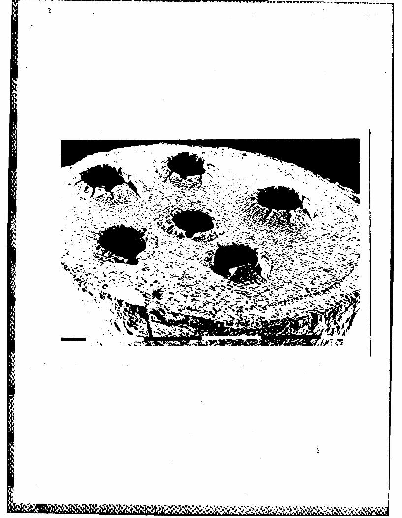
Figure 13
Acrylic resin retained in the etch. Note
difference (arrow) between the area of acrylic
resin attachment and the surrounding etched
me-al surface, 45X. Marker is one millimeter.

a~mtmp~ ~ - ~ sown.-.
rV. S

44
Figure 14A
Adhesive failure and plastic deformation of
the acrylic resin on beads at 20X.
Marker is one millimeter.

L D-At72 158 THE TENSILE AND SHEAR BOND STRENGTHS FPPOLY (METHYL 2/2
I METHACRYLATE) PROCES..(U) AIR FORCE INST OF TECH
UNCLASS IF iGHT-PRTTERSON AFB OH J E ZURASKY MAY 86F/1/9 NUNLSSFED F EEE/N-8-E8TFE 1/9 EI ~Flf...f..Ehhhhhhhhh7
11111 tL 8 12.5
!| I II11I1I1|1III Ii1 -i
aW. 332
I.25
MJCROCOPy RESOLUTION TEST CHARTNATIONAL BUREAU OF STANDARDS-1963.A
I

I v-

45
Figure 14B
Adhesive failure of the acrylic resin on
beads at 20X. Marker is one millimeter.
UKIiiir


46
TABLE 2
Shear Bond Strengths For The Etched And Bead Specimens
Etched Samples Bead Samples
number newtons number newtons
101 --------199 104 --------4031.02 --------223 105 ------- 480103 --------225 106 --------428107 --------380 108 ------- 588109 --------413 111 --------560110 ------- 399 112 --------562113 --------340 117 ------- 511114 ------- 365 118 ------- 571115 --------309 119 ------- 450116 ------- 368 122 --------506120 ------- 275 124 --------600121 --------431 125 --------335123 ------- 239 126 ------- 467127 --------390 128 --------508129 ------- 375 130 --------552133 ------- 424 131 --------565134 --------381 132 ------- 647135 ------- 298 136 ------- 403139 ------- 459 137 --------480140 ------- 302 138 ------- 556
RANGE: 199 - 459 RANGE: 335 - 647
MEAN: 345.7 newtons MEAN: 508.6 newtons12.22 MPa 17.97 MPa
STD DEV: 71.1 newtons STD DEV: 71.1 newtons2.51 MPa 2.51 MPa
T VAL: -6.89
D F: 38
P VAL: <0.001
111110 "

47
(12.22 MPa) with a standard deviation of 71.1 newtons
(2.51MPa). The mean shear bond strength for the bead
specimens was 508.6 newtons (17.97 MPa) with a standard
deviation of 71.1 newtons (2.51 MPa).
Although a Students' T-test on this data resulted in a
significantly higher bond strength for the bead specimens
these results are in question due to complications during
the shear bond testing.
Examination of the fracture sites using the scanning
electron microscope once again demonstrated cohesive failure
within the poly (methyl methacrylate) at the etched surface.
Acrylic resin fragments remained mechanically locked to the
micro-retention of the etching (Fig 15). Extensive plastic
deformation of the poly (methyl methacrylate) was evident
during examination of the fractured acrylic resin (Fig 16).
The shear fractured bead specimens again showed an
adhesive failure between the metal and the acrylic resin
with even more extensive plastic deformation of the poly
(methyl methacrylate) due to the shearing blade (Fig 17).
Some of the beads were sheared off by contact with the blade
as it cut into the acrylic resin (Fig 18).
11 ) 1111

48
Figure 15A
Acrylic resin adhering to the etched metal
surface after shear failure, 250X.
Marker is 0.1 millimeter.

lott

49
Figure 15B
Cohesive shear failure of the acrylic resin
on an etched specimen at 2000X.
Marker is 10 microns.

IL1

50
Figure 16
Surface of the acrylic resin rod after shear
failure from the etched surface at 20X.
Marker is one millimeter.
MOE


51
Figure 17
-4
Severe plastic deformation of the acrylic resin
sheared from a bead specimen at 20X. Note the
deformation due to the shearing blade.
Marker is one millimeter.


52
Figure 18
Metal bead specimen with the loss of two beads
due to contact with the shearing blade, 15X.
Marker is one millimeter.


VI. DISCUSSION
Fabrication and preparation of the test specimens were
accomplished with laboratory methods that are commonly used
for clinical prostheses. These same laboratory procedures
would be used for clinical application of the results of
this research.
The poly (methyl methacrylate) rod was waxed-up
directly on the etched surface of the metal. The waxed
metal was flasked in a denture flask and the wax boiled out
in the boiling tank. Wax solvent was used on the etching to
dissolve any remaining wax and then detergent was used to
remove any oily residue.
The etched surface was fully contaminated with these
materials, and then flushed with clean boiling water, and
allowed to dry before the acrylic resin was split-packed.
The effect of any manipulation or contamination of the
etched metal surface has not been studied in depth. It has
been reported by McLaughlin (1981, 1982) and Thompson and
Livaditis (1982) that the etched surface of the metal must
be maintained contamination-free to preserve the bonding
-capability. This research indicates that manipulation and
contamination may not be as critical as was originally
thought. Some consideration must be given to the packing
conditions of 3000 psi applied pressure which cannot be
directly compared to composite resins placed intraorally.
53

54
Meiers et al.(1985) looked at a variety of surface
treatments on the bond strength of etched metal retainers.
They found that abrasion with salivary contamination did not
ecrease the shear bond strength, and that the etched metal
surface may not be as fragile as was thought. It is evident
that further research is necessary in this area.
Controlling the etching conditions is one of the most
important factors in consistent etching. Metal etching is
the result of dissolution of the more corrodible elements in
the metal by the action of the acid in relation to current
and time. The etching occurs at a predictable rate and can
be controlled with attention to all details involved. Using
controlled times and currents with precisely measured acids
a 50-70 micron deep retentive etch can be obtained. The
etch should be verified using a stereo microscope in the 40-
60 power range. Interdendritic attack specific for the
metal etched can be seen. This uniform dendritic pattern is
not the sole retentive feature but is indicative of its
presence. The micro-retentive undercuts are apparent under
higher magnification.
The results of the tensile bond test show that
microscopic retention of the poly (methyl methacrylate) is
much more desirable than the accepted bead retention. The
etched tensile bond is nearly 3.5 times the strength of the
bond with beads. The etched bond is available over the
entire surface area in contrast to the limited retention
around the beads. It is probable that due to this increased

55
surface area of bonding there would be less metal-resin
interface percolation, staining, and odor.
These findings show that a very strong mechanical bond
is achievable between the etched metal base or removable
partial denture framework and the acrylic resin.
The results of the shear bond test show that although
shear testing is used frequently to evaluate the etched-
composite resin bond, this test is not appropriate for
quantifying the shear strength of poly (methyl methacrylate)
on beads. The shear test on the bead specimens initiated
extensive plastic deformation of the acrylic resin allowing
the shearing blade to penetrate into the acrylic resin
contacting the metal beads. The resulting bond strengths
are not a true representation of the actual bond.

VII. SUMMARY
This research examines the microscopic mechanical
bonding of acrylic resin to electrolytically etched base
metal alloy by comparing the etched tensile and shear bond
strengths to the clinically accepted macroscopic mechanical
bond of acrylic resin-to beads.
Tensile and shear bond strengths were quanitatively
measured on an Instron Universal Testing Machine and a
Scanning Electron Microscope was used to evaluate the
fracture sites.
The shear bond test for acrylic resin on beads was
found to be inappropriate. Excessive plastic deformation of
the acrylic resin allowed the shearing blade to penetrate
into the acrylic resin contacting the metal beads and
distorting the shear bond values. This does not
significantly affect the results or the conclusions of this
research due to the fact that clinical problems have been
reported to relate directly to tensile failures.
Table 3 is a summary of the tensile bond strengths
comparing the two systems. The tensile bond strength using
electrolytic etching to obtain microscopic retention of poly
(methyl methacrylate) on base metal alloy is much higher
than the accepted bead retention.
The following conclusions and recommendations can be
made from the results of this research:
1. The etched tensile bond is nearly 3.5 times the
56

57
Table 3
SUMMARY
TENSILE BOND STRENGTHS OF ETCHED AND BRAD SPECIMENS
Technique N Mean bond S.D.............................................................
Etched 20 16.70 MPa 4.60 MPa
Beads 20 4.77 MPa 2.68 MPa
P < 0.001

58
strength of the tensile bond with beads.
2. The tensile and shear fractures for the etched
specimens were a cohesive failure in the acrylic resin.
3. The tensile and shear fractures for the bead
specimens were total adhesive failures at the acrylic resin-
metal interface.
4. Protecting the etched surface against contamination
is not critical during the laboratory processing of poly
(methyl methacrylate) onto the etched surface.
5. The clinical applicability of this research can be
used on a base metal prosthesis where retention of acrylic
resin is necessary. This retention capability can salvage
an ill-fitting metal based denture by allowing a reline of
the intaglio surface. The acrylic resin will bond to the
metal over the entire etched surface area. Acrylic resin
retention has always been a problem where interarch space is
minimal. Microscopic etched retention preserves the maximum
remaining space for placement of artifical teeth.
6. Further research is indicated on this topic. One
area is the probable reduction of percolation, staining, and
odor at the acrylic resin-metal interface enhancing the
acceptability of the prosthesis. Another area is the
masking of the etched metal when only a thin layer of
acrylic resin is to cover the metal.
[a- %&e

APPENDICIES
Page
Appendix A - Raw Data Tensile Bond Strengths..... 61
Appendix B - Raw Data Shear Bond Strengths ...... 63
Appendix C - Manuifacturers and Materials ....... 65
Appendix D -Technical References ................. 66
59

APPENDIX A
Raw Data Tensile Bond Strengths
Specimen # Type Bond Strength (Newtons)
1 Bead 53
2 Bead 240
3 Etch 610
4 Etch 357
5 Etch 341
6 Bead 250
7 Etch 665
8 Etch 533
9 Etch 567
10 Bead 189
11 Bead 95
12 Bead 47
13 Bead 83
14 Bead 25
15 Bead 249
16 Bead 80
17 Bead 130
18 Etch 515
19 Bead 220
20 Bead 137
21 Etch 585
22 Etch 577
23 Etch 506
60
- MEN"

61
Raw Data Tensile Bond Strengths Continued
Specimen # Type Bond Strength (Newtons)
24 Etch 143
25 Bead 199
26 Etch 300
27 Etch 308
28 Etch 440
29 Etch 432
30 Etch 513
31 Bead 83
32 Bead 235
33 Etch 500
34 Etch 512
35 Bead 82
36 Etch 620
37 Bead 47
38 Bead 97
39 Bead 177
40 Etch 426

APPENDIX B
Raw Data Shear Bond Strengths
Specimen # Type Bond Strength(Newtons)
101 Etch 199
102 Etch 223
103 Etch 225
104 Bead 403
105 Bead 480
106 Bead 428
107 Etch 380
108 Bead 588
109 Etch 413
110 Etch 399
111 Bead 560
112 Bead 562
113 Etch 340
114 Etch 365
115 Etch 309
116 Etch 368
117 Bead 511
118 Bead 571
119 Bead 450
120 Etch 275
121 Etch 431
122 Bead 506
123 Etch 299
124 Bead 600
62
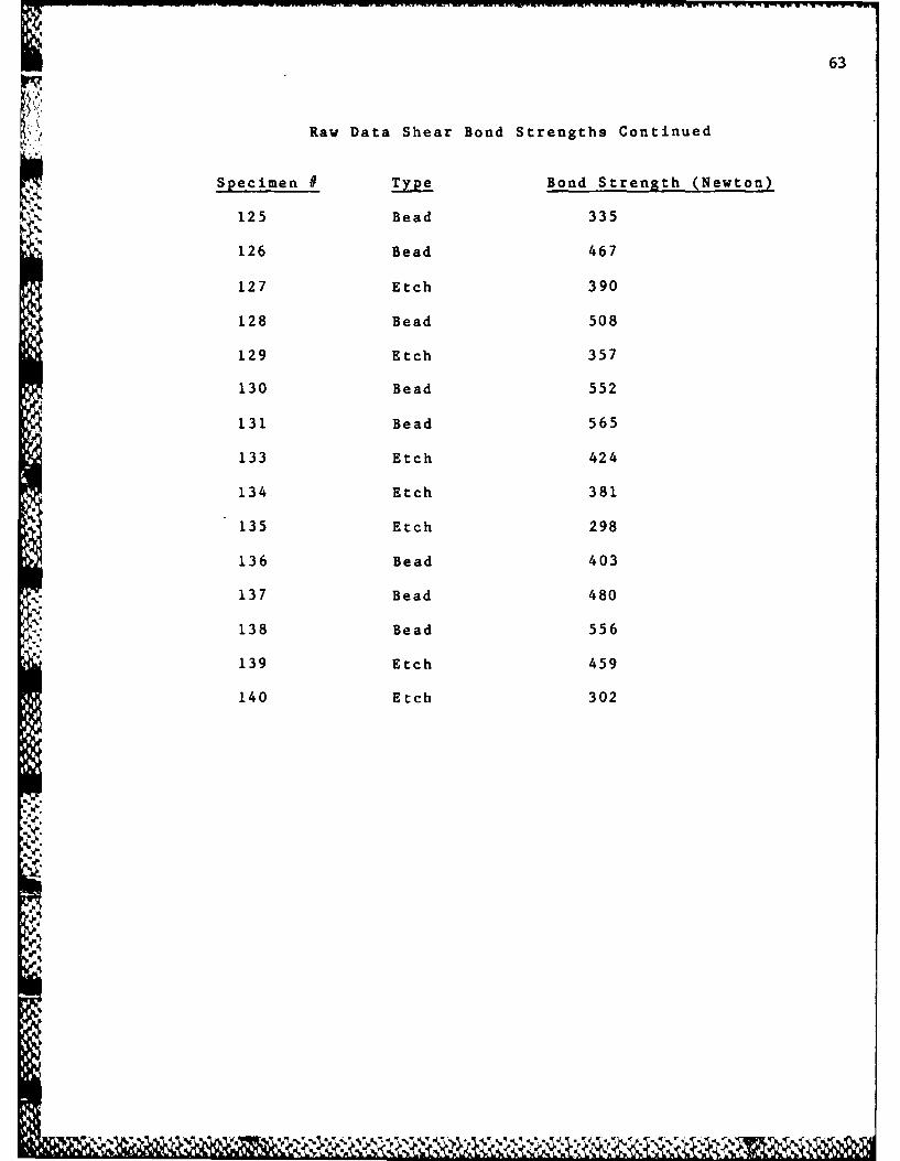
63
Raw Data Shear Bond Strengths Continued
Specimen # Type Bond Strength (Newton)
125 Bead 335
126 Bead 467
127 Etch 390
128 Bead 508
129 Etch 357
130 Bead 552
131 Bead 565
133 Etch 424
134 Etch 381
135 Etch 298
136 Bead 403
137 Bead 480
138 Bead 556
139 Etch 459
140 Etch 302
:N%

APPENDIX C
Manufacturers and Materials
1. Alcote - L.D. Caulk Company, Milford, Delaware.
2. Hanau Curing Unit - Hanau Engineering, Buffalo, New
York.
3. Hanau Denture Flask - Hanau Engineering, Buffalo, New
York.
4. Hygenic Baseplate Wax - Hygenic Corporation, Akaron,
Ohio.
5. Instron Universal Testing Machine - Instron
Corporation, Canton, Massachusetts.
6. Investic - Ticonlum Corporation, Albany, New York.
7. Kayon Beads - Kay See Dental Manufacture Company, Kanas
City, Missouri.
8. Lucitone 199 - L.D. Caulk Company, Milford, Delaware.
9. Phillips Model 505 Scanning Electron Microscope -
Phillips Company, Houston, Texas.
10. Ticomatic Auto Casting Machine - Ticonium Corporation,
Albany, New York.
11. Ticonium 100 - Ticonium Company, Albany, New York.
12. Ti-Lectro Polisher - Ticonium Corporation, Albany, New
York.
13. Time Etch - Dental Laboratories, Inc., Baltimore,
Maryland.
64
W121O II 'efi '' 1! )I V N Ll

APPENDIX D
Technical References
1. Time Etch -Dental Laboratories, Inc., Baltimore,
Maryland.
2. Ticonium Technique Manual - Ticonium Company, CMP
Industries, Albany, New York.
3. Inatron Operating Manual - Instron Corporation, Canton,
Massachusetts.
65

LITERATURE CITED
1. Al-Shamary, A., J. Meiers, T. Mayclin, and M. Jensen.1983. Bond strengths of etched metal to enamel:effects of different etching times. J. Dent Res. 62:221.
2. American Dental Association. 1976-1978. Guide to dentalmaterials and devices. 8th ed. American DentalAssociation. p. 206.
3. Anthony, D.H. and F.A. Peyton. 1962. Dimensionalaccuracy of various denture-base materials. J.Prosthet Dent. 12: 67-81.
4. Barnes, R.F. and P.C. Moon. 1982. Ni-Cr alloys pittingpotential in acid base, and salt solutions. IADRProgram and Abstracts. No. 610.
5. Barsby, N.J. and H. Braden. 1979. A hydrophilic denturebase resin. J. Dent Res. 58: 1581-1584.
6. Barsoum, W.M., J. Eder and K. Asgar. 1968. Evaluatingthe accuracy of fit of aluminum-cast denture basesand acrylic resin bases with a surface meter. J.AmDent Assoc. 76: 82-88.
7. Bertolotti, R.L. and L.J. Napolitano. 1983. Bonding ofIsosit to electrolytically etched nickel-chromiumsubstrate. IADR Program and Abstracts. No. 460: 220.
8. Braden, M. 1964. The absorption of water by acrylicresins and other materials. J. Prosthet Dent.14: 307-316.
9. Brauer, G.M. and W.T. Sweeney. 1955. Effects oftemperature and degree of polymerization onsorption of water by polymethyl methacrylates. ModPlastics. 32: 138-148.
10. Brauer, G.M., E.E. White, C.L. Burns, and J.B. Woelfel.1959. Denture reliners-direct, hard, self-curingresin. J. Am Dent Assoc. 59: 270-283.
11. Brauer, G.M. 1966. Dental applications of polymers:areview. J. Am Dent Assoc. 72: 1151-1158.
12. Buonocore, M.G. 1955. A simple method of increasing theadhesion of acrylic filling materials to enamelsurfaces. J. Dent Res. 34: 849-853.
66

67
13. Campbell, D.D. 1935. The cast swaged aluminum basedenture. J. AM Dent Assoc. 22: 2082-2089.
14. Campbell, D.D. 1936. The cast-aluminum base denture.J. Am Dent Assoc. 23: 1264-1270.
15. Castillo, E.D. and V.P. Thompson. 1982.Electrolytically etched NP alloys: resin bond andlaboratory variables. IADR Program and Abstracts.64: 186.
16. Caul, H.J., J.W. Stanford, and A.F. Serio. 1952.Properties of self-curing denture base resins. J. AmDent Assoc. 44: 295-298.
17. Chevitarese, 0., R.G. Craig, and F.A. Payton. 1962.Properties of various types of denture-baseplastics. J. Prosthet Dent. 12: 711-719.
18. Christensen, F.T. 1971. Relining techniques forcomplete dentures. J. Prosthet Dent. 26: 373-381.
19. Civjan, S., E.F. Huget, and L.B. de Simon. 1972.Modifications of the fluid resin technique. J. AmDent Assoc. 85: 109-112.
20. Cornell, J.A., J.L. Tucker, and C.M. Powers. 1960.Physical properties of denture-base materials. J.Prosthet Dent. 10: 516-524.
21. DeFurio, A. and D.H. Gehl. 1970. Clinical study of theretention of maxillary complete dentures withdifferent base materials. J. Prosthet Dent. 23: 374-380.
22. Dhillon, M., A.H. Fenton, and P.A. Watson. 1983. Bondstrengths of composite to perforated and etchedmetal surfaces. IADR Program and Abstracts. No.1219: 304.
23. Dootz, E.R. 1980. Fabricating non-precious metal bases.Dent Clin North Am. 24: 113-122.
24. Dunn, B. and M.H. Reisbick. 1976. Adherence of ceramiccoatings on chromium-cobalt structures. J. Dent Res.55: 328-332.
25. Dunny, J.A., and G.E. King. 1975. Minor connectordesigns for anterior acrylic resin bases: Apreliminary study. J. Prosthet Dent. 34: 496-502.
I II •I '' • 1 1
1 11 1 1 1 4 11 1 1 ,1 ' 1 1 1 1 1 1

68
26. Eshelman, R., P.C. Moon, H.B. Douglas, and M. Stall.1981. Retentive strength of acid-etched fixedprostheses. IADR Program and Abstracts. No.153: 154.
27. Esposito, C.J. 1981. Natural tooth pontic utilization.General Dent. Jan-Feb: 46.
28. Faber, B.L. 1957. Lower cast metal base denture. J.Prosthet Dent. 7: 51-54.
29. FitzRoy, D.C., H.L. Swartz, and R.W. Phillips. 1963.Physical properties of selected dental resins partII. J. Prosthet Dent. 13: 1108-1119.
29. Garfleld, R.E. 1984. An effective method for reliningmetal-based prostheses with acid-etch techniques.J. Prosthet Dent. 53: 719-721.
30. Grunewald, A.H. 1964. Gold base lower dentures. J.Prosthet Dent. 14: 432-441.
31. Halperin, A.R. 1980. The cast aluminum denture base.Part I: Rationale. J.Prosthet Dent. 43: 605-610.
32. Hamada, T., N. Shigeto, and T. Yanagihara. 1985. Adecade of progress for the adhesive fixed partialdenture. J. Prosthet Dent. 54: 24-29.
33. Hargreaves, A.S. 1978. Equilibrium water uptake anddenture base resin behavior. J. Dent. 6: 342-352.
34. Howe, D.F. and G.E. Denehy. 1977. Anterior fixedpartial dentures utilizing the acid-etch techniqueand a cast metal framework. J. Prosthet Dent. 37:28-31.
35. Jenkins, C.B.G. 1978. Etched-retained anteriorpontics. Br Dent J. 144: 206-208.
36. Jensson, J.S., K.F. Leinfelder, and J.E. Lemons. 1985.Ag-Pd alloys for resin bonded retainers. J. DentRes. 64: 297.
37. Johnson, W. and E. Mathews. 1949. Fatigue studies onsome dental resins. Br Dent J. 86: 252-260.
38. Johnston, E.P., J.I. Nicholls, and D.E. Smith. 1981.Flexure fatigue of 10 commonly used denture baseresins. J. Prosthet Dent. 46: 478-483.

69
39. Jordan, I.E., H. Suzuki, P.S. Sills, D.R. Graton, andJ.A. Gwinnett. 1978. Temporary fixed partialdentures fabricated by means of the acid-etch resintechnique: a report of 86 cases followed for up tothree years. J•Am Dent Assoc. 96: 994-1001.
40. Kapur, K.K. and E.E. Fischer 1981. Effect of denturebase thermal conductivity on gustatory response. J.Prosthet Dent. 6: 603-609.
41. Kelly, E.K. 1967. Flexure fatigue resistance of heat-curing and cold-curing polymethyl methacrylate. J.Am Dent Assoc. 74: 1273-1276.
42. Kelly, E. 1969. Fatigue fracture in denture basepolymers. J. Prosthet Dent. 21: 257-266.
43. Kelsey, C.C. 1971. Alveolar bone resorption undercomplete dentures. J. Prosthet Dent. 25: 152-161.
44. Kochavi, D., N. Stern, and R. Grajower. 1977. Atemporary space maintainer using acrylic resin teethand a composite resin. J. Prosthet Dent. 37: 522-526.
45. Kraut, R.A. 1971. A comparison of denture baseaccuracy. J. Am Dent Assoc. 83: 352-357.
46. Lambert, P.M., D.L. Moore, and H.H. Elleston. 1976. Invitro retentive strength of fixed bridgesconstructed with acrylic pontics and an ultraviolet-light-polymerized resin. J. Am Dent Assoc. 92: 740-743.
47. Lambrecht, J.R. and W.L. Kydd 1962. Functional stressanalysis of the maxillary complete denture base. J.Frosthet Dent. 12: 865-872.
48. Lang, B.R. 1974. The use of gold in construction of
mandibular denture bases. J. Prosthet Dent. 32:398-404.
49. Livaditis, G.J. 1980. Cast metal resin-bonded retainersfor posterior teeth. J. Am Dent Assoc. 101: 926-929.
50. Livaditis, G.J. and V.P. Thompson. Etched castings: animproved mechanism for resin-bonded retainers. J.Prosthet Dent. 47: 52-58.
51. Lundquist, D.O. 1963. An aluminum alloy as a denture-base material. J. Prosthet Dent. 13: 102-110.

70
52. Matthews, E. and E.A. Wain. 1956. Stresses in denturebases. Br Dent J. 100: 167-171.
53. McLaughlin, G. 1981. Composite bonding of etched metalanterior splint. Compendium Cont Educ Dent. 2: 279-283.
54. McLaughlin, C. and D. Foerth. 1982. Composite bondingof etched metal bridges. Gen Dent. 30: 132-135.
55. McLaughlin, G. 1982. One hundred second etch techniquefor etched-metal bridges. J. Mich Dent Assoc. 64:347-349.
56. McLaughlin, G. and J. Masek. 1985. Comparison of bondstrengths using one-step and two-step alloy etchingtechniques. J. Prosthet Dent. 53: 516-520.
57. Melers, J.C., M.E. Jensen, and T. Mayclin. 1985.Effect of surface treatments on the bond strength ofetched-metal resin-bonded retainers. J. ProsthetDent. 53: 185-189.
58. Mirza, F.D. 1961. Dimensional stability of acrylicresin dentures clinical evaluation. J. ProsthetDent. 11: 848-857.
59. soon, P.C. and F.J. Knap. 1983. Acid-etched bridge bondstrength utilizing a new retention method. IADRProgram and Abstracts. No.296: 682.
60. Moore, F.D. 1967. Organic or metal bases for dentures.J. Prosthet Dent. 17: 227-231.
61. Morrow, R.M., K.D. Rudd, and H.F. Eissman. 1980. DentalLaboratory Procedures Complete Dentures, Vol. 1Chapter 16 by Brudvik, J.S., C.V. Mosby, 1980.
62. Mowery, W.E., C.L. Burns, G. Dickson, and W.T. Sweeney.1958. Dimensional stability of denture base resins.J. Am Dent Assoc. 57: 345-353.
63. Nathanson, D. and K. Moin. 1980. Metal reinforcedanterior tooth replacement using acid-etch-compositeresin technique. J. Prosthet Dent. 43: 408-412.
64. Peck, C., A. Doukoudakis, and S.Doukoudakis. 1981. Theuse of acid-etch metal retainers. CDS Rev. 74: 27-29.

71
65. Peyton, F.A. and W.R. Mann. 1942. Acrylic and acrylic-styrene resins: Properties in relation to uses as arestorative material. J.Am Dent Assoc. 29: 1852-1864.
66. Pryor, W.J. 1928. Swaged denture bases. J. Am DentAssoc. 15: 1281-1288.
67. Pryor, W.J. 1943. Internal strains in denture basematerials. J. Am Dent Assoc. 30: 138201389.
68. Regli, C.P. and W.L. Kydd. 1953. A preliminary study ofthe lateral deformation of metal base dentures inrelation to plastic base dentures. J. Prosthet Dent.3: 326-330.
69. Regli, C.P. and H.L. Gaskill. 1954. Denture basedeformation during function. J.Prosthet Dent. 4:548-554.
70. Reinhardt, J.W., G.E. Denehy, and K.C. Chan. 1979. Acidetch bonded cast orthodontic retainers. Am J. Ortho.75: 138-142.-
71. Rochette, A.L. 1973. Attachment of a splint to enamelof lower anterior teeth. J. Prosthet Dent. 30: 418-423.
72. Shaffer, F.W. and W.H. Filler. 1971. Relining completedentures with minimum occlusal error. J. ProsthetDent. 25: 366-370.
73. Shepard, W.L. 1968. Denture bases processed from afluid resin. J. Prosthet Dent. 83: 561-572.
74. Sherman, J.R. and E.N. Komorech. 1985. Rebasing metal-based complete mandibular dentures. J. ProsthetDent. 53: 130-132.
75. Short, G.M., J.H. Hembree, and J.P. McKnight. 1976. Thebond strength of resin systems to etched enamel. J.Prosthet Dent. 36: 538-543.
76. Simonsen, E.W., V. Thompson, and G. Barrack. 1983.Etched Cast Restorations: Clinical and LaboratoryTechniques. Chicago, Quintessence Publishing Co.,42-44.
77. Sizeland-Coe, J.W. 1951. Cast aluminum alloy. Br DentJ. 91: 263-269.
. .l M

72
78. Skinner, E.W. and E.N. Cooper. 1943. Physicalproperties of denture resins: Part I. Curingshrinkage and water sorption. J. Am Dent Assoc. 30:1845-1852.
79. Sloan, K.M., R.E. Lorey, and G.E. Myers. 1983.Evaluation of laboratory etching of cast metal resinbonded retainers. J. Dent Res. 62: 305.
80. Smith, D.C. 1961. The acrylic denture. Br Dent J. 110:251-256.
81. Smith, D.C. 1961. The acrylic denture base; mechanicalevaluation of dental polymethyl-methacrylate. BrDent J. 111: 9-17.
82. Smith, D.C. 1961. Acrylic denture: mechanicalevaluation; midline fracture. Br Dent J. 110: 257-267.
83. Smith, D.C. 1962. Recent developements and prospects indental polymers. J. Prosthet Dent. 12: 1066-1078.
84. Stafford, G.D. and D.C. Smith. 1968. Some studies ofthe properties of denture base polymers. Br Dent J.125: 337-342.
85. Stafford, G.D. and H. Braden. 1968. Water absorption ofsome denture base polymers. J. Dent Res. 47: 341.
86. Stafford, G.D., T.T. Levis, and R. Huggett. 1982.Fatigue testing of denture base polymers. J. OralRehab. 9: 139-154.
87. Stolpa, J.B. 1975. An adhesive technique for smallanterior fixed partial dentures. J. Prosthet Dent.34: 513-519.
88. Stuart, I.A. 1974. An unusual space maintainer retainedby an acid etched polymer resin. Br Dent J. 137:437-438.
89. Swartz, W.H. 1966. Retention forces with differentdenture base materials. J. Prosthet Dent. 16: 458-463.
90. Sweeney, W.T., G.C. Paffenbarger, and J.R. Beall. 1942.Acrylic resins for dentures. J. Am Dent Assoc. 29:7-33.
91. Sweeney, W.T. 1958. Acrylic resins in prostheticdentistry. Dent Clin North Am. Nov: 593-602.
L . - , *

73
92. Sweeney, W.T., D.L. Moore, and J.J. Dooner. 1980.Retentive strength of acid-etched anterior fixedpartial dentures: An in vitro comparison ofattachment techniques. J. Am Dent Assoc. 100: 198-202.
93. Tallgren, A. 1966. The reduction in face height ofedentulous and partially edentulous subjects duringlong term denture wear; a longitudinalroentgenographic cephalometric study. Acta OdontScand. 24: 195-293.
94. Tanaka, T.,M. Atsuta, Y. Uchiyama, and I. Kawashima.1979. Pitting corrosion for retaining acrylic resinfacings. J. Prosthet Dent. 42: 282-291.
95. Thompson, V.P., G.J. Livaditis, and E. DelCastillo.1981. Resin bond to electrolytically etched non-precious alloys. IADR Program and Abstracts. No.265:377.
96. Thompson, V.P. 1982. Electrolytic etching modes ofvarious NP alloys for resin bonding. IADR Programand Abstracts. No.65.
97. Thompson, V.P. and G.J. Livaditis. 1982. Etched castingacid etch composite bonded posterior bridges.Pediatr Dent. 4: 38-43.
98. Thompson, V.P., K. Grolman, and R. Liao. 1984.Electrolytic etching of Co-Cr alloys for resinbonded restorations. J. Dent Res. 63: 324.
99. Tregarthen, G.G.T. 1949. The anodic treatment ofaluminum and its alloys for use in the mouth. BrDent J. 86: 227-232.
100. Vernon, L.B. and H.M. Vernon. 1941. Producing moldedarticles such as dentures from thermoplasticsynthetic resins. Chem Abs. 35: 4124.
101. White, K.C., C.W. Svare, and T.D. Taylor. 1985. Apotentiostatic study of corrosion behavior ofanodized and nonanodized aluminum alloy. J. ProsthetDent. 16: 815-819.
102. Williams, V.d., D.G. Drennon, and L.M. Silverstone.1982. The effect of retainer design on the retentionof filled resin in acid-etched fixed partialdentures. J. Prosthet Dent. 48: 417-423.

74
103. Winkler, S., H.R. Ortman, H.F. Morris, and R.A. Plezia.1971. Processing changes in complete denturesconstructed from pour resins. J. Am Dent Assoc. 82:349-353.
104. Winkler, S. 1972. The current status of pour resins.J. Prosthet Dent. 28: 580-584.
105. Woelfel, J.B. and G.C. Paffenbarger. 1959. Method ofevaluating the clinical effect of warping a denture:report of a case. J. Am Dent Assoc. 59: 250-260.
106. Woelfel, J.B., G.C. Paffenbarger, and W.T. Sweeney.1960. Dimensional changes occuring in denturesduring processing. J. Am Dent Assoc. 61: 413-430.
107. Woelfel, J.B., G.C. Paffenbarger, and W.T. Sweeney.1961. Changes in dentures during storage in waterand in service. J. Am Dent Assoc. 62: 643-657.
108. Woelfel, J.B. 1971. Newer materials and techniques inprosthetic resin materials. Dent Clin North Am. 15:67-79.
109. Yanover, L., W. Croft, and F. Pulver. 1982. The acid-etched fixed prosthesis. J. Am Dent Assoc. 104:325-328.

VITA
John E. Zurasky was born on the tenth of September,
1950, in New Castle, Pennsylvania. He graduated from
Shenango High School in May of 1968, and began his
undergraduate education at Youngstown State University,
Youngstown, Ohio, that year. He graduated with a Bachelor
of Science degree in Biology in March, 1973.
He was accepted for training at Temple University,
Philadelphia, Pennsylvania, as a freshman dental student in
August, 1973, and was awarded a Doctor of Dental Surgery
degree in May of 1977. After graduation he accepted a
M commission in the United States Air Force to practice
dentistry.
In July, 1983, he began graduate study in
Prosthodontics at the University of Texas Health Science
Center, San Antonio, Texas, sponsored by the United States
Air Force. One year later he was admitted as a candidate
for the Master of Science degree at the Graduate School of
Biomedical Sciences.
75

-' - - -Jill


![[Shinobi] Claymore 096](https://static.fdocuments.in/doc/165x107/568c485e1a28ab49168fdf2e/shinobi-claymore-096.jpg)


