ill Iii 1It 'Iii Itl I ill I I Iii 1It 'Iii Itl I 729I _____ AD TECHNICAL REPORT ARCCB-TR-91013...
24
AD-A235 729 ill I I Iii 1It 'Iii Itl I I _____________________ AD TECHNICAL REPORT ARCCB-TR-91013 CORRELATION BETWEEN MACHINE TWIST ANGLE AND UNIT TWIST ANGLE IN CALCULATING SHEAR STRESSES FOR ELASTIC AND PLASTIC STRAINS IN TORSION ROBERT R. FUJCZAK DTIC IELECT 0 MAY 2 3 1991 APRIL 1991 813 US ARMY ARMAMENT RESEARCH, DEVELOPMENT AND ENGINEERING CENTER CLOSE COMBAT ARMAMENTS CENTER BENET LABORATORIES WATERVLIET, N.Y. 12189-4050 APPROVED FOR PUBLIC RELEASE; DISTRIBUTION UNLIMITED 91-00209 91 1,I 045 I
Transcript of ill Iii 1It 'Iii Itl I ill I I Iii 1It 'Iii Itl I 729I _____ AD TECHNICAL REPORT ARCCB-TR-91013...

AD-A235 729ill I I Iii 1It 'Iii Itl I I _____________________
AD
TECHNICAL REPORT ARCCB-TR-91013
CORRELATION BETWEEN MACHINE TWISTANGLE AND UNIT TWIST ANGLE IN CALCULATING
SHEAR STRESSES FOR ELASTIC ANDPLASTIC STRAINS IN TORSION
ROBERT R. FUJCZAK
DTICIELECT 0
MAY 2 3 1991APRIL 1991 813
US ARMY ARMAMENT RESEARCH,DEVELOPMENT AND ENGINEERING CENTER
CLOSE COMBAT ARMAMENTS CENTERBENET LABORATORIES
WATERVLIET, N.Y. 12189-4050
APPROVED FOR PUBLIC RELEASE; DISTRIBUTION UNLIMITED
91-0020991 1,I 045 I

DISCLAIMER
The findings in this report are not to be construed as an official
Department of the Army position unless so designated by other authori:ed
documents.
The use of trade name(s) and/or manufacturer(s) does not constitute
an official indorsement or approval.
DESTRUCTION NOTICE
For classified documents, follow the procedures in DoD 5200.22-1,
Industrial Security Manual, Section 11-19 or DoD 5200.1-R, Information
Security Program Regulation, Chapter IX.
For unclassified, limited documents, destroy by any method that will
prevent disclosure of contents or reconstruction of the document.
For unclassified, unlimited documents, destroy when the report is
no longer needed. Do not return it to the originator.

SECURITY CLASSIFICATION OF THIS PAGE (Whar Data Entered)
REPORT DOCUMENTATION PAGE BRED ONSTUCTONSBEFORE COMPLETING FORM1. REPORT NUMBER 2. GOVT ACCESSION NO. 3. RECIPIENT'S CATALOG NUMBER
ARCCB-TR-91i013
4. TITLE (And Subtitle) S. TYPE OF REPORT & PERIOO COVERED
CORRELATION BETWEEN MACHINE TWIST ANGLE AND FinalUNIT TWIST ANGLE IN CALCULATING SHEAR STRESSESFOR ELASTIC AND PLASTIC STRAINS IN TORSION 6. PERFORMING ORG. REPORT NUMBER
7. AUTHOR(e) S. CONTRACT OR GRANT NUMBER(e)
Robert R. Fujczak
9. PERFORMING ORGANIZATION NAME AND ADDRESS 10. PROGRAM ELEMENT. PROJECT, TASKAREA & WORK UNIT NUMBERS
U.S. Army ARDEC AMCMS No. 6126.23.lBLO.OARBenet Laboratories, SMCAR-CCB-TL PRON No. lA9AN9BMlAH3Watervliet, NY 12189-4050
11. CONTrOLLN OFFICE NAME AND ADDRESS 12. REPORT DATE
U.S. Army ARDEC -April 1991
Close Combat Armaments Center 13. NUMBER OF PAGES
Picatinny Arsenal, NJ 07806-5000 1814. MONITORING AGENCY NAME & AOORESS('If different from Controlling Office) 1S. SECURITY CLASS. (of this report)
UNCLASSIFIED1S. OECLASSI FICATION/ DOWNGRAOINGSCHEDULE
16. DISTRIBUTION STATEMENT (of this aport)
Approved for public release; distribution unlimited.
17. DISTRISUTION STATEMENT (of the ebetract mtered In Bock 20, If different ham Report)
1. SUPPLEMENTARY NOTES
IS. KEY WORDS (Continue an revese side If necessary mid Identilf by block nuinber)
Torsion ElasticTwist Angle PlasticShear Stress Twist MomentShear Strain
2.. AIIIT' ACT' ('CA1mi e an @ N ,ne inv seat dh@lIfP' by block mimbr)
For a solid torsion bar, the ratio between the unit twist angle and themachine twist angle remains linear, even when the twist shows plasticdeformation. Therefore, the torsional stresses may be calculated from atorque-twist curve, whether the twist axis is unit twist angle or machinetwist angle. This allows for stress calculations beyond the limit of theunit twist gage.
IA 73 Lonno.. t Nov 6s5 OsOLETE UNCLASS IFIED
SECUITY CLASSIFICATION Op THIS PAGE (Sbn Date Entered)

TABLE OF CONTENTS
Page
INTRODUCTION .............................................................. 1
ELASTIC TORSION EQUATIONS ................................................. 1
PLASTIC TORSION EQUATIONS ................................................. 2
EXPERIMENTAL PROCEDURE .................................................... 4
DATA ANALYSIS ............................................................. 5
CONCLUSIONS ............................................................... 7
REFERENCES ................................................................ 9
TABLES
I. TORQUE DATA FOR 4150H SPEC AA-5 ........................................ 6
LIST OF ILLUSTRATIONS
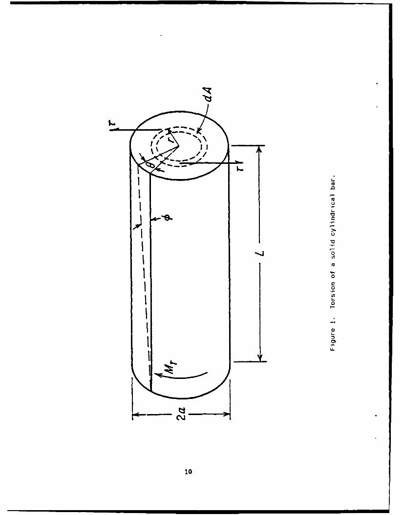
1. Torsion of a solid cylindrical bar .................................... 10
2. Method of calculating shear stress from torsion-twist curve ........... 11
3. Torsion test specimen ................................................. 12
4. Reproduction of experimental torsion-twist curve ...................... 13
5. Schematic of torsion-twist curve ...................................... 14
6. Comparison of calculated torsional stress values ...................... 15
7. Ratio between unit twist angle and machine twist angle ................ 16
8. Static torsion plot calculated from machine twist angle data .......... 17
Aoession For
NTIS GRA&I
DTIC TABUnannounced 0Just Ifititon
4 By
Distributlou/
AvailabIity Codes
Dist Special.F ' I

INTRODUCTION
In certain applications such as spring testing and twist testing of solid
or hollow shafts, the torsion test has been valuable. However, it has not been
as widely accepted and utilized as the tension test. Therefore, it has not been
standardized to the same extent as the tension test. Material specifications
rarely require torsion tests, therefore, the data are less common than tensile
data (refs 1-3).
Torsion-testing equipment consists of a twisting head, with a chuck for
gripping the specimen and for applying the twisting moment to the specimen, and
a fixed end. Specimen deformation may be determined by unit twist angle over a
specified gage length, but this method is limited to a small angular range, 4 to
5 degrees/inch gage length. Another measurement that may be determined during
testing is the machine twist of the chuck applying the twist moment. This
report shows the correlation between the machine twist angle and the limited
unit twist angle and how they both can be used to calculate shear stress, even
in the case of large plastic strains.
ELASTIC TORSION EQUATIONS
Figure 1 is a schematic of a torsional moment, MT, on a cylindrical bar.
The twisting moment is opposed by shear stresses in the bar cross section. The
shear stress, T, is zero at the center of the bar and increases linearly with
the radius, r. The following is an equation of the twisting moment:
r=a T aMT f ruO TrdA = r'dA (1)
r=O r 0

However, f radA is J, the polar moment of inertia of the area with respect
to the axis of the bar. Therefore,
TJMT r
or
MTr (2)TF = - - )
where T z shear stress, psi
MT = torsional moment, in.-lb
r = radial distance measured from center of bar, in.
J = polar moment of inertia, in. 4
Since the shear stress is a maximum at the outside surface of the bar, for
a solid cylindrical specimen where J = n3/32, the maximum shear stress is
MTO/2 16MT (3)Tmax = ziF7 = (3)
The angle of twist, 6, is usually expressed in radians. If L is the test
length of the specimen, from Figure 1 it can be seen that the shear strain, y,
is given by
= tan 0 - r9 (4)
where t = the torsional angular displacement across the gage length, L. This
angle, y, remains constant over any gage length, so twist angle 6 is directly
related to the gage length.
PLASTIC TORSION EQUATIONS
Once the torsional yield strength is surpassed, the shear stress over the
cross section is no longer a linear function of the distance from the axis, and
Eqs. (2) and (3) do not apply. Nadai (ref 4) presented a method to calculate
2
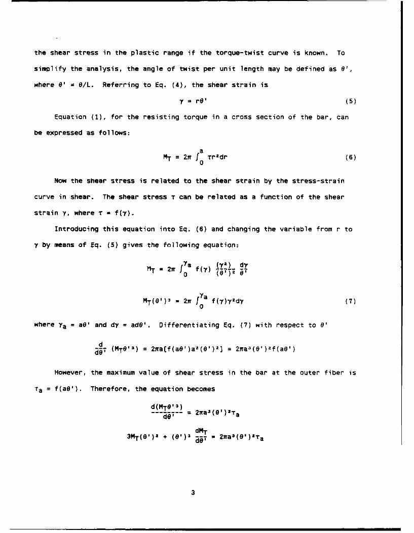
the shear stress in the plastic range if the torque-twist curve is known. To
simplify the analysis, the angle of twist per unit length may be defined as 6',
where 9' = 9/L. Referring to Eq. (4), the shear strain is
Y = r9' (5)
Equation (1), for the resisting torque in a cross section of the bar, can
be expressed as follows:
MT = 27t a Tr2dr (6)
0
Now the shear stress is related to the shear strain by the stress-strain
curve in shear. The shear stress T can be related as a function of the shear
strain y, where T = f(7).
Introducing this equation into Eq. (6) and changing the variable from r to
y by means of Eq. (5) gives the following equation:
MT = 27 f f(7) (0,) d'
0 ( 53)2 6'
MT(e')3 = 21 f a fly)y2dy (7)
0
where 7a = a8' and dy = ade'. Differentiating Eq. (7) with respect to 0'
daT (MTe'3) = 2,a[f(aO')a 2 (0')2 ] = 27ra 3(e')Zf(aO')
However, the maximum value of shear stress in the bar at the outer fiber is
Ta = f(aO'). Therefore, the equation becomes
d(MTO'3)W -= 2ffa3(9')2T adO'
dMT3MT(e')a + (e')3 a5 = 27ra 3(e')Ta
3

Rearranged, the equation becomes
1 dMT 1Ta = e[ + 3M (8)
The shear stress may be calculated with Eq. (8) if a torque-twist curve is
available. Figure 2 shows a schematic of how this is done. Equation (8) can be
rewritten in terms of geometry shown in Figure 2 as follows:
1Ta 2a (BC + 3CD) (9)
It can also be noticed from Figure 2 that at the maximum value of torque
the derivative dMT/d@' = 0. Therefore, the ultimate torsional shear strength
or modulus of rupture can be expressed by the following equation:
T 3Mmax
u = 2,ra(
If Eq. (9) is used at or before the elastic limit, then MT = BC = CD, and
since a = D/2, Eqs. (3) and (9) are equivalent up to this point. Thus, Eq. (9)
may be used throughout the entire elastic-olastic range.
EXPERIMENTAL PROCEDURE
Figure 3 shows the torsional test specimen designed for use in an Instron
Model No. 1323 Triaxial Test Machine, capable of static and fatigue testing in
combinations of 100,000 lb tension-compression, 50,000 in.-lb torsion, and
50,000 psi pressure. In our case, only the static torsion capability was used.
The specimen was mounted in the twist chucks with instrumentation moni-
toring applied torque, unit twist angle, and machine twist angle at the chuck
position. Figure 4 shows a reproduction of the original plot. The lower curve
represents the unit twist angle from the biaxial extensometer, which had a
4

maximum capacity of only about 5 degrees twist. So, this extensometer was
removed before 5 degrees twist to prevent gage damage. Also, the upper curve
represents the applied machine twist angle, but at over 40 degrees twist up to a
value close to the maximum twist moment. The maximum twist moment also aopears
on the curve, but without any twist angle data, because the plasticity exceeded
the machine's angle measurement capacity.
DATA ANALYSIS
Data points were taken from the curves in Figure 4, and Figure 5 represents
a schematic of both machine angle and unit twist angle versus machine torque.
Since calculation of the shear stresses along the torque-twist curve depends on
derivatives, a cubic spline technique (ref 5) was used. The raw data and calcu-
lated values appear in Table I. Data for unit twist and machine twist angles
were taken at equivalent torque values up to the limit of the unit twist values.
After that, only machine twist values were recorded.
The first column in Table I is untitled and just identifies the data points
as "pt 0," "pt 1," etc., taken from Figure 4. The next column entitled "Mach"
contains values for the machine twist angle in total degrees. The column
entitled "Unit" contains values for the unit twist angle in degrees/inch and is
limited to less than 5 degrees/inch. The column entitled "M(T)" contains values
of machine torque in in.-lb from minimum to maximum torque.
The column entitled "dy/dx" contains values of the derivatives calculated
by the cubic spline approximation for the unit twist curve, and the column
entitled "(dy/dx)M" contains values for the machine twist curve. "Tau-a" refers
to the values of the shear stresses calculated from Eq. (9) using the unit twist
derivative values. "Tau-M" refers to the values of the shear stresses using the
machine twist derivative values.
5

TABLE I. TORQUE DATA FOR 4150H SPEC AA-51
Mach Unit M(T) (dy/dx)M Tau-a dy/dx Tau-M
pt 0 0.00 0.00 0 4,626.8& 0.00 16,868.75 0.00
pt 1 1.75 0.48 8,097 3,963.30 a1,237.68 16,868.75 39,759.16
pt 2 3.00 0.85 12,218 2,894.50 57,381.58 9,898.10 57,725.50
pt 3 4.25 1.20 15,369 2,377.00 71,198.65 8,176.91 71,567.84
pt 4 5.55 1.59 18,278 1,869.50 83,192.97 6,607.30 83,027.60
pt 5 7.10 2.01 20,702 1,664.40 92,283.91 5,161.00 94,121.99
Pt 6 8.45 2.53 23,126 1,616.70 001,669.05 4,139.40 105,728.68
pt 7 10.00 3.06 25,066 1,082.80 108,406.27 3,249.70 109,531.71
pt 8 11.85 3.73 27,005 945.80 115,405.34 2,580.20 117,421.63
pt 9 14.25 4.55 28,944 752.40 122,810.64 2,115.00 124,209.23
pt 10 16.25 30,399 655.40 129,675.95
pt 11 20.20 32,338 397.80 133,753.25
pt 12 25.00 34,035 291.40 139,279.67
pt 13 29.75 35,102 140.00 139,382.81
Pt 14 34.70 35,732 68.00 139,490.52
pt 15 40.00 36,023 37.50 139,507.58
pt 16 60.00 36,556 0.00 139,633.63
6

By using Eq. (9) from the torque-twist diagram for unit twist and also
machine twist angle, the torsion stress may be calculated either way. Figure 6
shows a comparison of torsional stress values calculated from both twist angles.
Although the twist angles from each method are different with respect to twist
moment, their corresponding derivative values yield comparable torsional stress
values.
Figure 7 shows that the torsional stress calculated from unit twist is very
closely related to the strp:s calculated from machine twist. Therefore, the
machine twist angle may be used to calculate torsional stress with reasonable
accuracy, using the limited unit twist angle to calculate torsional strain.
Figure 8 shows the static torsion plot calculated from the machine twist
angle. Since the ratio between machine twist and unit twis.r is roughly 4 to 1,
the machine twist data beyond about 16 degrees, or beyond the unit twist limit
of about 4 degrees/inch, is the only means by which the torsional stress may be
calculated up to maximum value.
CONCLUSIONS
1. For a solid torsion bar of 4150H steel, the ratio between the unit
twist angle and the machine twist angle remains basically the same, even when
the twist shows plastic defcrmation. For the configuration used herein, the
ratio between machine angle and unit twist angle, 0/01, is approximately 3.2.
For every degree of unit twist, the machine twist is about 3.2 degrees.
2. Torsional stresses may be calculated by g the slopes from a torque-
twist curve, whether the twist is uaiit twist per inch gage length or machine
twist measured at the twisting head.
7

3. Since torsional stress may be calculated throughout the elastic-plastic
range with the plastic equation, either twist may be used to calculate torsional
stress up to the capability limit of the unit twist gage, but beyond that point
the only method available to calculate torsional stress is the machine twist
angle.
8

REFEREPCES
1. G.E. Dieter, "The Torsion Test," in: Mechanical Metallurgy, Chapter 10,
Third Edition, McGraw-Hill, Inc., New York, 1986.
2. J. Marin, Mechanical Behavior of Enqineering Materials, Chapter 2,
Prentice-Hall, Inc., Engiewood Cliffs, NJ, 1962.
3. Metals Handbook, "Torsion Testing," 9th Edition, American Society for
Metals, Metals Park, OH, Vol. 8, 1985, pp. 137-184.
4. A. Nadai, Theory of Flow and Fracture of Solids, 2nd Edition, Vol. I,
McGraw-Hill Book Company, New York, 1950, pp. 347-349.
5. A. Ralston and P. Rabinowitz, A First Course in Numerical Analysis,
McGraw-Hill, Inc., New York, 1978.
9
.00,,
.0
0
'4-
100

- C.-
II-
4-
A
, , zU " ;-',
". I C04 1*
I" 0
ZH ')uaJo).u 5u! !,,L
II -I., '4

- , " I
I _,.
I _...
I . I D
I U
-'I i-; ,-°*0
l I i '-.I

..... ...
.. n :. . .
I' .~ L ... JL
14 Y r.:j ....
It 13

0-00
E- \
10
Cr a.
C_ 0z
E"Hy
Z - -_1 4

Ci))
40
00
E-4 E
0~ 0.
z 0
C Z/r72. 0
0

TAU(T) vs. TAU(M)FOR 4150H SPECIMEN AA-51
UNIT TWIST TORSION STRESS (Thousands)150
125
100
75
50
25
00 25 50 75 100 125 150
MACHINE TORSION STRESS (Thousands)CALCULATED FROM UNIT TWIST (TAU(T))AND MACME TWIST (TAU(M))
Figure 7. Ratio between unit twist angle and machine twist angle.
16

-n0-
cfn
_ _ 0 0
E--
0 C
0 CQ 0 r- 0 0
17

TECHNICAL REPORT INTERNAL DISTRIBUTION LIST
NO. OFCOPIES
CHIEF, DEVELOPMENT ENGINEERING DIVISIONATTN: SMCAR-CCB-D 1
-DA 1-DC 1-DI 1-OP 1-DR 1-OS (SYSTEMS) 1
CHIEF, ENGINEERING SUPPORT DIVISIONATTN: SMCAR-CCB-S 1
-SE 1
CHIEF, RESEARCH DIVISIONATTN: SMCAR-CCB-R 2
-RA 1-RE 1-RM 1-RP 1-RT 1
TECHNICAL LIBRARY 5ATTN: SMCAR-CCB-TL
TECHNICAL PUBLICATIONS & EDITING SECTION 3ATTN: SMCAR-CCB-TL
DIRECTOR, OPERATIONS DIRECTORATE 1ATTN: SMCWV-OD
DIRECTOR, PROCUREMENT DIRECTORATE 1ATTN: SMCWV-PP
DIRECTOR, PRODUCT ASSURANCE DIRECTORATE 1ATTN: SMCWV-QA
NOTE: PLEASE NOTIFY DIRECTOR, BENET LABORATORIES, ATTN: SMCAR-CCB-TL, OFANY ADDRESS CHANGES.

TECHNICAL REPORT EXTERNAL DISTRIBUTION LIST
NO. OF NO. OFCOPIES COPIES
ASST SEC OF THE ARMY COMMANDERRESEARCH AND DEVELOPMENT ROCK ISLAND ARSENALATTN: DEPT FOR SCI AND TECH ATTN: SMCRI-ENMTHE PENTAGON ROCK ISLAND, IL 61299-5000WASHINGTON, D.C. 20310-0103
DIRECTORADMINISTRATOR US ARMY INDUSTRIAL BASE ENGR ACTVDEFENSE TECHNICAL INFO CENTER ATTN: AMXIB-PATTN: DTIC-FDAC 12 ROCK ISLAND, IL 61299-7260CAMERON STATIONALEXANDRIA, VA 22304-6145 COMMANDER
US ARMY TANK-AUTMV R&D COMMANDCOMMANDER ATTN: AMSTA-ODL (TECH LIB)US ARMY ARDEC WARREN, MI 48397-5000ATTN: SMCAR-AEE 1
SMCAR-AES, BLDG. 321 1 COMMANDERSMCAR-AET-O, BLDG. 351N 1 US MILITARY ACADEMYSMCAR-CC 1 ATTN: DEPARTMENT OF MECHANICSSMCAR-CCP-A 1 WEST POINT, NY 10996-1792SMCAR-FSA 1SMCAR-FSM-E 1 US ARMY MISSILE COMMANDSMCAR-FSS-D, BLDG. 94 1 REDSTONE SCIENTIFIC INFO CTR 2SMCAR-IMI-I (STINFO) BLDG. 59 2 ATTN: DOCUMENTS SECT, BLDG. 4484
PICATINNY ARSENAL, NJ 07806-5000 REDSTONE ARSENAL, AL 35898-5241
DIRECTOR COMMANDERUS ARMY BALLISTIC RESEARCH LABORATORY US ARMY FGN SCIENCE AND TECH CTRATTN: SLCBR-DD-T, BLDG. 305 1 ATTN: DRXST-SDABERDEEN PROVING GROUND, MD 21005-5066 220 7TH STREET, N.E.
CHARLOTTESVILLE, VA 22901DIRECTORUS ARMY MATERIEL SYSTEMS ANALYSIS ACTV COMMANDERATTN: AMXSY-MP 1 US ARMY LABCOMABERDEEN PROVING GROUND, MD 21005-5071 MATERIALS TECHNOLOGY LAB
ATTN: SLCMT-IML (TECH LIB) 2Cn.4MANDER WATERTOWN, MA 02172-0001HQ, AMCCOMATTN: AMSMC-IMP-L 1ROCK ISLAND, IL 61299-6000
NOTE: PLEASE NOTIFY COMMANDER, ARMAMENT RESEARCH, DEVELOPMENT, AND ENGINEERINGCENTER, US ARMY AMCCOM, ATTN: BENET LABORATORIES, SMCAR-CCB-TL,WATERVLIET, NY 12189-4050, OF ANY ADDRESS CHANGES.

TECHNICAL REPORT EXTERNAL DISTRIBUTION LIST (CONT'D)
NO. OF NO. OFCOPIES COPIES
COMMANDER COMMANDERUS ARMY LABCOM, ISA AIR FORCE ARMAMENT LABORATORYATTN: SLCIS-IM-TL 1 ATTN: AFATL/MN2800 POWDER MILL ROAD EGLIN AFB, FL 32542-5434ADELPHI, MD 20783-1145
COMMANDERCOMMANDER AIR FORCE ARMAMENT LABORATORYUS ARMY RESEARCH OFFICE ATTN: AFATL/MNFATTN: CHIEF, IPO 1 EGLIN AFB, FL 32542-5434P.O. BOX 12211RESEARCH TRIANGLE PARK, NC 27709-2211 METALS AND CERAMICS INFC CTR
BATTELLE COLUMBUS DIVISIONDIRECTOR 505 KING AVENUEUS NAVAL RESEARCH LAB COLUMBUS, OH 4Z201-2693ATTN: MATERIALS SCI & TECH DIVISION 1
CODE 26-27 (DOC LIB) 1WASHINGTON, D.C. 20375
DIRECTORUS ARMY BALLISTIC RESEARCH LABORATORYATTN: SLCBR-IB-M (DR. BRUCE BURNS) 1ABERDEEN PROVING GROUND, MD 21005-5066
NCT.: PLEASE NOTIFY COMMANDER, ARMAMENT RESEARCH, DEVELOPMENT, AND ENGINEERINGCENTER, US ARMY AMCCOM, ATTN: BENET LABORATORIES, SMCAR-CCB-TL,WATERVLIET, NY 12189-4050, OF ANY ADDRESS CHANGES.