ActiLume Wireless DALI nd Generation - I-Production cms...
78
ActiLume Wireless DALI 2 nd Generation OEM application guide
-
Upload
nguyendiep -
Category
Documents
-
view
214 -
download
0
Transcript of ActiLume Wireless DALI nd Generation - I-Production cms...

ActiLume Wireless DALI
2nd GenerationOEM application guide

Philips ActiLume DALI 2nd Generation 1-2

Philips ActiLume DALI 2nd Generation - Contents i-3
Contents
1 What is ActiLume Wireless DALI 2nd Generation 1-6
2 Product characteristics 2-72.1 ActiLume gen2 multi-sensor LRI1663 2-7
2.1.1 IR receiver 2-82.1.2 Light sensor 2-82.1.3 Movement detector 2-92.1.4 Presence detector indicator 2-92.1.5 Other sensor specifications 2-9
2.2 ActiLume Wireless DALI gen2 LLC1686 2-102.3 Dimensions ActiLume Wireless DALI gen2 2-102.4 Electrical characteristics 2-102.5 Limitation on number of devices per network 2-112.6 Default values for various timings 2-12
3 ActiLume Wireless DALI gen2 application modes 3-133.1 Out of the box behavior 3-133.2 Behavior after configuring 3-14
3.2.1 Mode 1 - Cell office - auto on 3-143.2.2 Mode 2 - Open office - auto on comfort mode 3-143.2.3 Mode 3 – Cell office - manual on 3-143.2.4 Mode 4 - Open office - manual on 3-153.2.5 Mode 5 - Non-working area - always on 3-153.2.6 Mode 6 - Max savings – off when vacant 3-153.2.7 Mode 7 - Comfort – off when vacant 3-153.2.8 Mode 8 - Max savings – always on 3-153.2.9 Mode 9 - Comfort – always on 3-153.2.10 Mode 10 - Non-working area – off when vacant 3-163.2.11 Mode 11 - Non-working area – manual on/auto off 3-163.2.12 Mode 12 … 15 - Free for OEM 3-16
3.3 Mode settings- overview 3-17
4 Occupancy sharing 4-184.1 Without zones 4-184.2 With zones 4-18

Philips ActiLume DALI 2nd Generation - Contentsi-4
5 Creating a new network 5-195.1 Determining the state of a ActiLume Wireless DALI gen2 system 5-195.2 Reset of a ActiLume Wireless DALI gen2 system 5-205.3 Creating a network with ActiLume Wireless DALI gen2 system 5-215.4 Adding luminaires to a new network 5-225.5 Closing a network 5-235.6 Locking a network 5-245.7 Unlocking a network 5-255.8 Removing a luminaire from a network 5-265.9 Creating zones in a network 5-265.10 Removing a luminaire from a zone 5-275.11 Adding wireless devices to an existing network 5-28
5.11.1 Adding a sensor, from the OSW family, to a network 5-295.11.2 Removing (resetting) a OSW sensor from a network 5-295.11.3 Adding a UID8410 device to a network 5-305.11.4 Removing a UID8410 from a network 5-315.11.5 Introduction to ZigBee Green Power (ZGP) devices 5-325.11.6 Adding a UID8450 ZGP switch to a network 5-325.11.7 Adding a UID8451 ZGP switch to a network 5-325.11.8 Adding a UID8460 ZGP scene selector to a network 5-335.11.9 Adding a UID8461 ZGP scene selector to a network 5-34
6 Changing default settings (configuring) 6-356.1 Changing the application mode 6-366.2 Request active Mode 6-366.3 Setting the background level 6-386.4 Changing Power-up-state 6-386.5 Setting the network IR group address 6-396.6 Changing the RF channel 6-406.7 Walk test 6-416.8 100 hour burn-in 6-416.9 Disable the motion sensor (PIR) 6-426.10 Selecting motion sensor (PIR) sensitivity 6-436.11 Selecting motion sensor (PIR) behavior 6-446.12 Selecting daylight sensor behavior 6-456.13 Change hold time 6-466.14 Automatic DDR set-point calibration 6-466.15 Selecting a set-point correction factor 6-476.16 Manual DDR set-point calibration (network level) 6-486.17 Manual DDR set-point calibration (luminaire level) 6-486.18 Introduction to scenes 6-49
6.18.1 Storing scenes with IRT9090 6-496.18.2 Storing scenes with UID8410 6-506.18.3 Scene recall with IRT9090 6-506.18.4 Scene recall with UID8410 6-516.18.5 Scene recall with IRT8030 6-516.18.6 Scene recall with IRT8050 6-526.18.7 Scene recall with UID8510 6-536.18.8 Scene recall with UID8460 6-546.18.9 Scene recall with UID8461 6-54
6.19 Some general default settings 6-556.20 DDR set-point calibration considerations 6-56

Philips ActiLume DALI 2nd Generation - Contents i-5
7 Manual control 7-597.1 Touch and Dim (push button) control 7-597.2 Wiring 7-597.3 Infra-Red (IR) control 7-60
7.3.1 Using the IRT8030 7-607.3.2 Using the IRT8050 7-607.3.3 Using the UID8510 7-61
7.4 RF control 7-617.4.1 Using the UID8410 7-617.4.2 Using UID8450 7-627.4.3 Using UID8451 7-627.4.4 Using UID8460 7-627.4.5 Using UID8461 7-63
8 Built in requirements 8-648.1 Wiring inside the luminaire 8-648.2 Wiring outside the luminaire 8-648.3 Mounting 8-64
8.3.1 Sensor LRI1663 8-648.3.2 Sensor cable 8-668.3.3 Sensor position 8-668.3.4 Controller LLC1686 8-668.3.5 Wiring to and from the controller 8-67
8.4 System capabilities and limitations 8-688.5 Connection examples 8-69
9 OccuSwitch wireless movement detectors 9-70
10 MultiOne 10-7210.1 Starting MultiOne software 10-7210.2 Gaining access to a ActiLume Wireless DALI gen2 network 10-73
11 FAQ 11-74
12 Abbreviations 12-77

Philips ActiLume Wireless DALI 2nd Generation - Ch 1 What is ActiLume Wireless DALI 2nd Generation1-6
1 What is ActiLume Wireless DALI 2nd Generation
The ActiLume Wireless DALI gen2 system is a new easy to install and easy to use luminaire based control
solution. It is suitable for office and industrial environments and offers maximum comfort and automatic energy/
CO2 savings. The system can switch luminaires (artificial light) automatically on and off, based on occupancy, and
dims them when enough daylight (natural light) enters the area.
Although the ActiLume Wireless DALI gen2 system is intended to be used as an easy to install system, some configuration (commissioning) will usually be needed. Configuration is done by means of an infrared (IR) remote control. This will set the artificial light according to the designer’s requested light level, switch the controller off or dim the light after a certain period of time. By means of the IRT9090 IR remote control a network, also known as a Controlled Area, with a maximum of 50 ActiLume Wireless DALI gen2 systems can be created. The network can be divided into 32 different zones and in addition scenes can be programmed and selected or a specific light level can be set.
The ActiLume Wireless DALI gen2 system consists of a sensor and a control unit, both designed to be built into a luminaire. The sensor contains four functions - a light sensor for daylight dependent light level regulation (DDR), a movement sensor for occupancy control, a infra-red sensor for receiving information from IR remotes and a LED indicator for status purposes. The lighting can also be controlled manually by a wired switch with a momentary contact (Touch and Dim). The system can operate with any DALI compatible ballast/driver.
The ActiLume Wireless DALI gen2 is a luminaire based lighting control system. The luminaires are connected and mounted in either the ceiling or free floor standing equipment. Through the IRT9090 remote the required light level can be adjusted and stored into the ActiLume Wireless DALI gen2 system as a DDR set-point. Other IR remotes can be used to set light level and/or recall scenes. With the configuration (commissioning) procedure as described in this document, several devices can be linked together so they will act as one system. Once configured the system is ready for use.
As the system’s name already implies, it can also be controlled via a secured radio connection which makes use of the ZigBee protocol (2.4GHz, 2007/ZigBee PRO), using a specific remote control. With this remote control limited functions are available for personal control of lights.Various other Philips ZigBee devices, such as OccuSwitch Wireless (OSW) sensors and ZigBee Green Power (ZGP) switches and scene recall, can be integrated into the network.Note that encrypted commands are used for communication between the Philips ZigBee devices and ActiLume Wireless DALI gen2 systems.
Another method of configuration is using a USB2ZigBee (LCN8650) dongle in combination with Philips MultiOne software but be aware that an IRT9090 is always needed to create a network and bring it into the correct state.For example to link the USB2ZigBee dongle the network has to be “Opened network” state and to make changes to the configuration the network needs to be in the “Test and Configuration” state. These states can only be set with the IRT9090.

Philips ActiLume DALI 2nd Generation - Ch 2 Product characteristics 2-7
The ActiLume Wireless DALI gen2 system consists of the following basic components:4LLC1686/11 ActiLume Wireless DALI gen2 (LLC1686)4LRI1663/00 ActiLume gen2 multi-sensor (LRI1663)
Figure 1 LLC1686
Figure 2 LRI1663
Additional components are:
4An infrared remote control intended for installers and facility managers to make the commissioning easier:4IRT9090 for advanced commissioning for all modes
and to change several default factory values4Infrared remote controls intended for end users:4IRT80304IRT80504UID8510
All can be used to personalize the light levels with preset dim values, scene setting or manual override of light levels. Detailed remote controls information can be found in chapter 7.3.
4An RF remote control4UID8410
4Additional OccuSwitch Wireless (OSW) movement sensors to assure movement is detected wherever needed.4LRM1763 (ceiling sensor)4LRM1765 (corridor sensor)4LRM1770 (corner sensor)4LRM1775 (wall sensor)
These sensors communicate with ActiLume Wireless DALI gen2 controller(s) using the ZigBee protocol.
4Additional ZigBee Green Power (ZGP) wireless control devices.4UID8450 and UID8451 ZGP on/off and dim devices
(both with the same functionality but with different outline)
4UID8460 and UID8461 ZGP scene recall and off devices (both with the same functionality but with different outline)
2.1 ActiLume gen2 multi-sensor LRI1663
The ActiLume gen2 multi-sensor contains four functional devices in a single housing and is wired with a connection cable of one meter to the controller. The functional devices are:
• Infrared receiver
• Light detector
• Movement detector (PIR)
• Presence detector indicator
Figure 3
The application area of ActiLume gen2 multi-sensor is a typical indoor environment (offices, corridors, meeting rooms, etc.) in normally heated and ventilated areas. ActiLume gen2 multi-sensor has no protection against aggressive chemicals or water (pollution degree 2). The sensor is normally mounted inside a Class I luminaire and is optimized for a ceiling height of 2.5 to 3 meter.
2 Product characteristics
This chapter will cover the product characteristics of the ActiLume Wireless DALI gen2 controller and sensor.
NoteLLC1686, ActiLume Wireless DALI gen2, can also be used in combination with LRI1667, ActiLume G2 Indus Sensor H513, but this is not further covered in this document. Details on LRI1667 ActiLume G2 Indus Sensor H513 can be found in the datasheet.

Philips ActiLume Wireless DALI 2nd Generation - Ch 2 Product characteristics2-8
The mounting height can reach up to 5 meter but the sensitivity patterns of the sensors will change accordingly.
2.1.1 IR receiverThe infrared receiver serves as a communication portal for the commissioning tool (IRT9090) and also for the following user interfaces:
4IRT80304IRT80504UID8510
The angle under which the IR receiver is able to receive RC5 codes is 55° in a 360 degree circle.
Figure 4
Figure 5
2.1.2 Light sensorThe (day)light sensor is a photo diode that reads actual average luminance in Candela per m2 captured under an angle of approximately 72º. The intensity of the luminance depends on the amount of artificial and/or natural light supplied in the office as well as how well this light is reflected towards the ceiling/sensor. The light reflection depends highly on the color and structure of the materials chosen to furbish the office, and can vary between 0.1 for pure dull black to 0.5 for a complete glossy white furnished office.
In an average office the reflection factor is approximately 0.3. The luminance signal is sent continuously to the ActiLume Wireless DALI gen2 controller. The ActiLume Wireless DALI gen2 controller translates these signals into dimming commands in order to get a constant light level on the desk of approximately 600 lux (factory default value).
The daylight sensor should be installed with a minimum distance of 0.6 meter from the window to avoid the sensor looking outside.
When the sensor is mounted too close to the window it will look partly outside. Sun reflection from a car bonnet or a window of a car or snow can reflect directly into the sensor. The sensor will then measure such high luminance levels that it will drive the artificial light to its minimal level or even switch off the artificial lights. The optimum distance [Y] from the window to the ActiLume gen2 multi-sensor can be obtained from the graph below. This graph shows the relation between the distance from the window to the sensor [Y] and the height [H] of the sensor.
Figure 7
Figure 8
sensor
1.8m
Remotecontrol
2.2m
1.25m
55°
luminaire
Figure 6 100 140 180 220 260 300
Nominal �eld of view
340 380 420 460 500H (cm)
50
70
90
110
130
150
170
190
210
230
250
270
290
310
330
350
370
Y (
cm)
Ø3.9m.
2.7m.
NoteDaylight information is not shared with Actilume Wireless DALI gen2 controllers across a created network.

Philips ActiLume Wireless DALI 2nd Generation - Ch 2 Product characteristics 2-9
2.1.3 Movement detectorThe occupancy sensor is a Passive Infra-Red (PIR) sensor that detects movement with an X-Y cross-area under an angle of X = 72º and Y = 85º. When installed in a typical office ceiling at 2.7 meter height, it is sensitive for small movements within a 4 by 5 meter area. It will cover small movements down to a few centimeters at the task area of a desk and is sensitive to large movements within a range of 6 by 8 meter
Figure 10
Though the sensor has a radial reach of 5 meter, the maximum recommended height to place the sensor in the ceiling is 3 meter to assure movement coverage and detection. The PIR sensor reacts on movement, by means of a temperature difference between for example a human body versus its surrounding. Wireless extension sensors can be combined with the ActiLume Wireless DALI gen2 system, and are used to increase the movement detection range. Wireless sensors have specific detection ranges and patterns and more information on these sensors can be found in chapter 9.
2.1.4 Presence detector indicatorThe presence detector indicator has the following function:Steady red : presence/movement detectedSteady yellow : Sensor is working but no presence/movement detectedNo color : LED indication is malfunctioning
Figure 11
2.1.5 Other sensor specificationsActiLume gen2 multi-sensor (LRI1663) has an RJ10 (4p4c) connector fixed to a cable. The length of the cable is 100 centimeters. The sensor housing (casing) material is Polycarbonate UL94 V-0 and the color is dark grey (5 NC 10714 which is close to RAL 7024 “Graphite grey”). The housing is resistant to the glow wire test 850 ºC / 5 seconds and has a basic insulation ≥ 1500 V. The dimensions, in millimeter, of the sensor are shown below.
Figure 12
6.0m.
8.0m.
4.0m.
5.0m.
2.7m.
Figure 9
NoteOccupancy information is shared with other ActiLume Wireless DALI gen2 controllers across the same network. Depending on the configuration, the behavior can differ (refer to chapter 4).
44.7
16.415.8

Philips ActiLume Wireless DALI 2nd Generation - Ch 2 Product characteristics2-10
2.2 ActiLume Wireless DALI gen2 LLC1686
The LLC1686 is the heart of the system. It will take care of all the communication to the ballasts / drivers connected in a way that is freely programmable or in a standard way by selecting a specific mode. There are 2 DALI outputs available that are internally connected in parallel. The LLC1686 ActiLume Wireless DALI gen2 has various pre-programmed modes but if needed all functions can be programmed freely like switching the daylight sensor, on or off, independently of the PIR sensor.
A network can be created in a very simple way as (parallel) linking is done wirelessly. Within a network up to 32 zones can be created, giving additional and flexible functionality to the system.
Figure 13
More on these configurations and how to change default settings can be found in the various chapters of this document.
2.3 Dimensions ActiLume Wireless DALI gen2
Figure 14 (dimensions are in millimeter)
2.4 Electrical characteristics
Some of the most important electrical characteristics that have to be kept in mind are the following:
4Both DALI ports have only basic insulation with respect to the mains. Since it is only basic insulation, a mains rated cable should be used when one or both DALI lines are brought outside the luminaire in which the ActiLume Wireless DALI gen2 is placed. Also a strain relief on the DALI line(s) is mandatory in this case. This is to ensure safety under all conditions.
4The Touch and Dim input is mains voltage and should be treated as such, according to local standards and regulations. The usage of a strain relief and mains rated cable is mandatory.
4The front of the sensor ensures double insulation. Nevertheless, if the sensor is used outside the luminaire or in a different luminaire than the ActiLume Wireless DALI gen2 is placed, mains rated extension cables and strain reliefs must be used.
4Only one LRI1663 ActiLume gen2 multi-sensor can be connected to a LLC1686 ActiLume Wireless DALI gen2.
Furthermore, the DALI connections will be powered by the ActiLume itself, so there is no need for any external power supply. The total load on the DALI lines is maximum 8mA. Since the two DALI lines are placed in parallel, the currents drawn from both connections need to be added up.
The absolute maximum rating for the DALI connection(s) for all configurations is 12mA.
179.5 mm
22.1 mm
30 m
m
167.5 mm
4.2
mm
!WarningIt is not allowed to connect an extra power supply to any of the DALI connections. This will permanently damage the ActiLume Wireless DALI gen2.

Philips ActiLume Wireless DALI 2nd Generation - Ch 2 Product characteristics 2-11
2.5 Limitation on number of devices per network
The number of ActiLume Wireless DALI gen2 controllers (LLC1686) that can be placed into a wireless network is limited to 50. Apart from that, there are also limitations on the amount of other ZigBee devices that are part of a network. These limitations can be found in the following table:
Table 1
Besides the above mentioned devices some additional (ZigBee and IR) devices can be used within the network.The function of these devices, and limitation on the amount that is allowed in a network, are mentioned in the next table:
Table 2
Since the ActiLume Wireless DALI gen2 is only capable of supplying 8mA to the DALI line, the maximum number of devices that can be connected to it is 4. It is not allowed to connect an extra (external) power supply to any of the DALI connections. This will permanently damage the ActiLume Wireless DALI gen2 system(s).
Category Device type(s) Minimum # Maximum # Intelligent luminaire LLC1686 1 50
Wireless sensors LRM1763 0 10
LRM1765
LRM1770
LRM1775
Manual control UID8410 0 5
Remark(s)Luminaire(s) can be with and without
multi-sensor. ActiLume Wireless devices
have the system setting Region set to EU.
Note: during configuration/commisioning
an ActiLume gen2 multi-sensor LRI1663
needs to be connected to each ActiLume
Wireless DALI gen2 controller
A system shall not contain more sensors
than controllers. If there are no sensors in
the luminaires, at least 1 wireless sensor
must be present.
Wireless Scene Control
Category Device type(s) Minimum # Maximum # Manual control UID8450 0 5
UID8451
UID8460
UID8461
IRT8030 0 no restriction
IRT8050
UID8510
Commissioning IRT9090 1 no restriction
LCN8650 0 1
Remark(s)ZigBee Green Power switch and dim
ZigBee Green Power scene selector
These IR remotes support only limited
functionality
At least one is needed for commissioning
MultiOne software is needed for this
dongle

Philips ActiLume Wireless DALI 2nd Generation - Ch 2 Product characteristics2-12
2.6 Default values for various timings
In ActiLume Wireless DALI gen2 there are several timers for when to do something after last movement has been detected. Within the various different modes these timers can have a different value. The timers, with their default and range value, are:4Fade to switch On time4Hold time4Grace time4Prolong time4Smart time
As soon as no movement has been detected anymore, all timers start in the following sequence (refer to figure below).
Fade to switch On time is the time, triggered when occupancy is detected, from T1 to T2 whereby the light level is gradually increased to Switch On level prior to going into DDR regulation if applicable. This function gives additional comfort as lights will gradually dim up.The following times are the default values (default times cannot be modified):41 second for Modes 1 … 5 and 11 … 1540 seconds for Modes 6 … 10
The period T2 to T3 is when occupancy is detected and the lights are regulated.
Hold time is the time from T3 to T4 whereby occupancy is no longer detected but the lights are still on and being regulated.The following times are the default values:415 minutes for Modes 1 … 4 and 12 … 1445 minutes for Modes 5, 7, 9 … 11and 1542 minutes for Modes 6 and 8
The possible values are 0.5, 1, 1.5, 2, 3, … 35 minutes.
Figure 15
Grace time is the time from T4 to T5 during which the lights are being dimmed down from the current light level to the background level.The following time is the default value:410 seconds for all Modes (1 … 15)
Possible values are 0, 1, 2, 3, … 25 seconds.
Prolong time is the time from T5 to T6 at which the background level is maintained at a fixed level. Modes have different prolong times.The following times are the default values:4Infinite for Modes 5, 8 and 9 (meaning the lights are not
switched off)430 minutes for Mode 10415 minutes for Mode 245 minutes for Mode 740 minutes for Modes 1, 3, 4, 6 and 11 … 15
Possible values for prolong time are 0, 1, 2, 3, … 150 and infinite.
Smart time is a period of time that extends the Hold time (T3 to T4) by several minutes if during the Grace time (T4 to T5) occupancy is detected. This time extension is only done once. After the next T4 the smart timer will be switched off again. The following times are the default values:410 minutes for Modes 1 … 4 and 12 … 1540 minutes for Modes 5 … 11
Possible values are 0, 1, 2, … 15 minutes.
T3 T4 T5 T6T1 T2

Philips ActiLume Wireless DALI 2nd Generation - Ch 3 ActiLume Wireless DALI gen2 application modes 3-13
3 ActiLume Wireless DALI gen2 application modes
This chapter gives an overview of the modes in which the ActiLume Wireless DALI gen2 system can be used.
ActiLume Wireless DALI gen2 has 15 pre-programmed application modes in which a group of luminaires can be controlled according to the table below.
Mode Description Office areas Mode 1 Cell office - auto on Mode 2 Open office - auto on comfort mode Mode 3 Cell office - manual on Mode 4 Open office - manual on comfort mode Mode 5 Non-working area - always on Industry areas Mode 6 Max savings – off when vacant Mode 7 Comfort – off when vacant Mode 8 Max savings – always on Mode 9 Comfort – always on Mode 10 Non-working area – off when vacant Mode 11 Non-working area – manual on/auto off Free for OEM Mode 12 (copy of Mode 1) Mode 13 (copy of Mode 1) Mode 14 (copy of Mode 1) Mode 15 (Hold time is 5min. the rest similar to Mode 1)
Table 3
Depending on the required application (lighting design) a different mode can be chosen. Paragraphs 3.2 through 3.12 and table 5 give additional information on mode behavior and settings.
3.1 Out of the box behavior
Please note that the ActiLume Wireless DALI gen2 system has a startup period of approximately 30s., in which period the behavior is not clearly defined. One should always wait for at least the 30s. startup period before starting to use or configure the system.
To make it easier for the installer to recognize if the luminaire is functioning before any configuration is done, the ActiLume Wireless DALI gen2 will be in a so called out of the box (OOTB) state. This means, when the luminaire is powered, the lights will always be switched on and the ActiLume Wireless DALI gen2 will have a certain behavior (see also table below) so it is clear all is functioning. If for whatever reason no occupancy is detected the system will directly enter the prolong time sequence of the OOTB behavior. The OOTB behavior is only active as long as the ActiLume Wireless DALI gen2 has not been placed into a network in other words when no configuration has taken place. As soon as the ActiLume Wireless DALI gen2 has been placed into a network, the mode related behavior will be enabled and the OOTB behavior will be switched off.
Each mode has a predefined set of functions in the out of the box behavior.
Mod
e 1
Mod
e 2
Mod
e 3
Mod
e 4
Mod
e 5
Mod
e 6
Mod
e 7
Mod
e 8
Mod
e 9
Mod
e 10
Mod
e 11
Mod
e 12
Mod
e 13
Mod
e 14
Mod
e 15
Power-up state On On On On On On On On On On On On On On OnHold Time [min] 15 15 15 15 15 15 15 15 15 15 15 15 15 15 15Background level [%] 20 20 20 20 20 30 30 30 30 30 20 20 20 20 20Prolong Time [min] 15 15 15 15 15 ∞ ∞ ∞ ∞ ∞ 15 15 15 15 15
Table 4

Philips ActiLume Wireless DALI 2nd Generation - Ch 3 ActiLume Wireless DALI gen2 application modes3-14
3.2 Behavior after configuring
As soon as configuration (creating a network) is started, the ActiLume Wireless DALI gen2 will leave the OOTB behavior and will start to behave as defined within the mode settings. How this behavior is will be explained in the next paragraphs. A final, short, overview on all the modes is given at the end of this chapter.
3.2.1 Mode 1 - Cell office - auto onThis mode is defined as “less comfort more savings” in particular for a cell office. It has fully automated behavior meaning the lights will be switched on when entering the room and switched off when the room is left unoccupied. When entering the room all lights will switch on and go to background level except for the luminaires that are in the same zone as the luminaire that detected the presence, they will all go to DDR.
When the room is occupied the daylight dependent regulation (DDR) is active and will keep the light level on the surface below the sensor on a constant level. The set point of the DDR is as such that on average the light level on the surface below the sensor will be approximately 600 lux.If the room is vacated for 15 minutes, the hold time has expired, and the lights will be switched off.
Figure 16
3.2.2 Mode 2 - Open office - auto on comfort modeMode 2 functions in principle in the same way as Mode 1 but with the difference that in this mode, the lights do not turn off after the hold time (15 minutes) has expired but are set to a background light level. This is to avoid that in those parts of an open plan office where people are still working they are not looking into a completely dark area. This will give more comfort but less saving. As soon as all ActiLume Wireless DALI gen2 report vacant, a prolong timer will be activated and after 15 minutes all lights will be switched off.
Figure 17
3.2.3 Mode 3 – Cell office - manual onMode 3 is very suitable for cell offices where maximum savings are required. To gain this the lights need to be switched on manually and DDR is enabled. This mode functions approximately the same as Mode 1 though in this mode the lights must always be switched on manually when entering the room. When the last person has left the room, the lights will be turned off automatically after the hold time (15 minutes) has expired.
Manual switch onThe manual switch on function is to prevent that lights switch on when people are just passing or only shortly need to be in the room to get something and the amount of light coming through the windows is sufficient for that. For this Manual On application an IRT8030, IRT8050, UID8410, UID8450, UID8451, UID8460 or UID8461 remote control can be used.
Figure 18
15 min.Mode 1
Auto onAuto off
15 min. 15 min.Mode 2
Auto onAuto off
Mode 4
Manual onAuto off
15 min.
Mode 5
Always on
15 min. ∞ Mode 6
Auto onAuto off
2 min.
Mode 7
Auto onAuto off
5 min. 5 min.
Mode 10
Auto onAuto off
15 min. 30 min.
Mode 11
Manual onAuto off
5 min.
Mode 3
Manual onAuto off
15 min.
Mode 8
Always on
2 min. ∞
Mode 9
Always on
5 min. ∞
15 min.Mode 1
Auto onAuto off
15 min. 15 min.Mode 2
Auto onAuto off
Mode 4
Manual onAuto off
15 min.
Mode 5
Always on
15 min. ∞ Mode 6
Auto onAuto off
2 min.
Mode 7
Auto onAuto off
5 min. 5 min.
Mode 10
Auto onAuto off
15 min. 30 min.
Mode 11
Manual onAuto off
5 min.
Mode 3
Manual onAuto off
15 min.
Mode 8
Always on
2 min. ∞
Mode 9
Always on
5 min. ∞ 15 min.Mode 1
Auto onAuto off
15 min. 15 min.Mode 2
Auto onAuto off
Mode 4
Manual onAuto off
15 min.
Mode 5
Always on
15 min. ∞ Mode 6
Auto onAuto off
2 min.
Mode 7
Auto onAuto off
5 min. 5 min.
Mode 10
Auto onAuto off
15 min. 30 min.
Mode 11
Manual onAuto off
5 min.
Mode 3
Manual onAuto off
15 min.
Mode 8
Always on
2 min. ∞
Mode 9
Always on
5 min. ∞

Philips ActiLume Wireless DALI 2nd Generation - Ch 3 ActiLume Wireless DALI gen2 application modes 3-15
3.2.4 Mode 4 - Open office - manual onManual on, more comfort (as in open plan office)
Mode 4 functions in a similar way to Mode 2 except in this mode the lights must be switched on manually, and will be switched off automatically once no presence is detected and the hold time has expired. Again here DDR is enabled to give additional energy saving. For this Manual On application an IRT8030, IRT8050, UID8410, UID8450, UID8451, UID8460 or UID8461 remote control can be used.
Figure 19
3.2.5 Mode 5 - Non-working area - always onMode 5 functions just like Mode 1 except in this Mode the lights will never switch off and the set-point for the DDR is set to a lower level. This mode is very useful for an area for moving from one place to another for example a corridor where lights should not be switched off.
Figure 20
3.2.6 Mode 6 - Max savings – off when vacantMode 6 is designed for use in areas where there should be only light if there is someone in the area. This means that the lights will switch automatically on when the area is entered and will switch off after a hold time of 2 minutes. In this Mode DDR is disabled
Figure 21
3.2.7 Mode 7 - Comfort – off when vacantComfort, lights off when vacant
Mode 7 is designed for use in areas where lights must switch on automatically, upon occupancy detection and stay on for the 5 minutes hold time after the area is unoccupied. After the hold time has expired the lights will go to background level during the 5 minutes prolong time before automatically being switched off. This mode creates a more comfortable feeling than Mode 6 but is less energy saving. In this Mode DDR is disabled.
Figure 22
3.2.8 Mode 8 - Max savings – always onThis mode gives a lot of savings by dimming back to background level as soon as there has been not presence detected for 2 minutes. On the other hand the lights will not be switched off but a very low light level will be maintained. In this Mode DDR is disabled.
Figure 23
3.2.9 Mode 9 - Comfort – always onThis mode functions in the same way as Mode 8 only the hold timer will be extended to 5 minutes and also here the lights will not be switched off but be maintained at a very low light level. In this Mode DDR is disabled.
Figure 24
15 min.Mode 1
Auto onAuto off
15 min. 15 min.Mode 2
Auto onAuto off
Mode 4
Manual onAuto off
15 min.
Mode 5
Always on
15 min. ∞ Mode 6
Auto onAuto off
2 min.
Mode 7
Auto onAuto off
5 min. 5 min.
Mode 10
Auto onAuto off
15 min. 30 min.
Mode 11
Manual onAuto off
5 min.
Mode 3
Manual onAuto off
15 min.
Mode 8
Always on
2 min. ∞
Mode 9
Always on
5 min. ∞
15 min.Mode 1
Auto onAuto off
15 min. 15 min.Mode 2
Auto onAuto off
Mode 4
Manual onAuto off
15 min.
Mode 5
Always on
5 min. ∞ Mode 6
Auto onAuto off
2 min.
Mode 7
Auto onAuto off
5 min. 5 min.
Mode 10
Auto onAuto off
5 min. 30 min.
Mode 11
Manual onAuto off
5 min.
Mode 3
Manual onAuto off
15 min.
Mode 8
Always on
2 min. ∞
Mode 9
Always on
5 min. ∞
15 min.Mode 1
Auto onAuto off
15 min. 15 min.Mode 2
Auto onAuto off
Mode 4
Manual onAuto off
15 min.
Mode 5
Always on
15 min. ∞ Mode 6
Auto onAuto off
2 min.
Mode 7
Auto onAuto off
5 min. 5 min.
Mode 10
Auto onAuto off
15 min. 30 min.
Mode 11
Manual onAuto off
5 min.
Mode 3
Manual onAuto off
15 min.
Mode 8
Always on
2 min. ∞
Mode 9
Always on
5 min. ∞
15 min.Mode 1
Auto onAuto off
15 min. 15 min.Mode 2
Auto onAuto off
Mode 4
Manual onAuto off
15 min.
Mode 5
Always on
15 min. ∞ Mode 6
Auto onAuto off
2 min.
Mode 7
Auto onAuto off
5 min. 5 min.
Mode 10
Auto onAuto off
15 min. 30 min.
Mode 11
Manual onAuto off
5 min.
Mode 3
Manual onAuto off
15 min.
Mode 8
Always on
2 min. ∞
Mode 9
Always on
5 min. ∞

Philips ActiLume Wireless DALI 2nd Generation - Ch 3 ActiLume Wireless DALI gen2 application modes3-16
3.2.10 Mode 10 - Non-working area – off when vacantMode 10 is an Auto on and Auto off Mode whereby DDR is enabled. Lights will be switched off after a prolong time of 30 minutes.
Figure 25
3.2.11 Mode 11 - Non-working area – manual on/auto offMode 11 is a Mode whereby lights need to be switched on manually, DDR is enabled and there is no prolong time so after the hold time has expired the lights will fade to off. For this Manual On application an IRT8030, IRT8050, UID8410, UID8450, UID8451, UID8460 or UID8461 remote control can be used.
Figure 26
3.2.12 Mode 12 … 15 - Free for OEMModes 12 to 14 are an exact copy of Mode 1. Mode 15 has a different hold time than Mode 1 but is for the rest similar. These Modes are created to offer free space to create your own modes with your own settings. When sending a reset to the ActiLume Wireless DALI gen2, these Modes will not be reset to factory default but will stay with the settings as they were created.
15 min.Mode 1
Auto onAuto off
15 min. 15 min.Mode 2
Auto onAuto off
Mode 4
Manual onAuto off
15 min.
Mode 5
Always on
5 min. ∞ Mode 6
Auto onAuto off
2 min.
Mode 7
Auto onAuto off
5 min. 5 min.
Mode 10
Auto onAuto off
5 min. 30 min.
Mode 11
Manual onAuto off
5 min.
Mode 3
Manual onAuto off
15 min.
Mode 8
Always on
2 min. ∞
Mode 9
Always on
5 min. ∞
15 min.Mode 1
Auto onAuto off
15 min. 15 min.Mode 2
Auto onAuto off
Mode 4
Manual onAuto off
15 min.
Mode 5
Always on
15 min. ∞ Mode 6
Auto onAuto off
2 min.
Mode 7
Auto onAuto off
5 min. 5 min.
Mode 10
Auto onAuto off
15 min. 30 min.
Mode 11
Manual onAuto off
5 min.
Mode 3
Manual onAuto off
15 min.
Mode 8
Always on
2 min. ∞
Mode 9
Always on
5 min. ∞

Philips ActiLume Wireless DALI 2nd Generation - Ch 3 ActiLume Wireless DALI gen2 application modes 3-17
3.3 Mode settings- overview
Table 5
Mod
e 1
Mod
e 2
Mod
e 3
Mod
e 4
Mod
e 5
Mod
e 6
Mod
e 7
Mod
e 8
Mod
e 9
Mod
e 10
Mod
e 11
Mod
e 12
Mod
e 13
Mod
e 14
Mod
e 15
Application Settings Range / units
Out Of The Box behavior
Power-up state lights ON lights OFF Hold time [min] 15 15 15 15 15 15 15 15 15 15 15 15 15 15 15Background level [%] 20 20 20 20 20 30 30 30 30 30 20 20 20 20 20Prolong time [min] or ∞ 15 15 15 15 15 ∞ ∞ ∞ ∞ ∞ 15 15 15 15 15Start-up and Dim behavior Power-up state lights ON lights OFF Set Point 1, 2, 3, …. 300 lux on sensor 210 210 210 210 70 80 120 80 120 80 80 210 210 210 210Background level minimal, 10, 20, … 70% 10 20 10 20 10 10 20 10 20 10 10 10 10 10 10Fading to Switch-On level Cannot be modified 1 1 1 1 1 0 0 0 0 0 1 1 1 1 1Delay and Switching-off behavior Hold Time 0.5, 1.0, 1.5, 2.0, 3.0, …, 35 min 15 15 15 15 5 2 5 2 5 5 5 15 15 15 5Smart Time 0, 1, 2, 3, …, 15 min 10 10 10 10 0 0 0 0 0 0 0 10 10 10 10Grace Fading Enable Disable Grace Time 0, 1, 2, …., 25 s. 10 10 10 10 10 10 10 10 10 10 10 10 10 10 10Prolong Time 0, 1, 2, 3, … 150 min or ∞ 0 15 0 0 ∞ 0 5 ∞ ∞ 30 0 0 0 0 0Light Control Daylight regulation cutoff 1, 2, 3, … 50 % 5 5 5 5 5 40 40 40 40 10 5 5 5 5 5Occupancy mode AutoOn - AutoOff ManualOn - AutoOff ManualOn - ManualOff Daylight Dependent Override: Enable Disable Daylight Dependent Regulation Enable Disable Daylight Dependent Switching; Enable Disable Switch on level prior fading to DDR 1, 2, 3, …, 100% 60 60 60 60 60 60 60 60 60 60 60 60 60 60 60

Philips ActiLume Wireless DALI 2nd Generation - Ch 4 Occupancy sharing4-18
4.1 Without zones
When a network is created without zones, occupancy detected by one ActiLume Wireless DALI gen2 is distributed across the whole network and all other ActiLume Wireless DALI gen2 will go into background-level, unless the occupancy sensor (PIR) is disabled, than it will go to max output.
4.2 With zones
When a network is created with zones, occupancy detected by one ActiLume Wireless DALI gen2 is distributed across the whole network. All ActiLume Wireless DALI gen2 within the zone, where occupancy has been detected, will react in the same way. All other ActiLume Wireless DALI gen2 that are in the same network but in a different or no zone, will react on the occupancy signal by going to background level.
4 Occupancy sharing
The ActiLume Wireless DALI gen2 has the possibility to share its occupancy status with other ActiLume Wireless
DALI gen2. The ActiLume Wireless DALI gen2 will distribute its occupancy status across the network. Depending
on how the network is buildup, with or without zones, it will react in a slightly different way.

Philips ActiLume Wireless DALI 2nd Generation - Ch 5 Creating a new network 5-19
70% G
min
100 h
group
link? mode?
mode
power up background IR group reset
add
pirdelay daylight RF channel
0
0
o�
save
on
I/ II
O)))
A-G
zone
%on/o�
87 950% E40% D 60% F
54 620% B10% A
II
30% C
PLBMS W/C
21 3
test
con�g
scene
Network(s) can be created with the IRT9090 Extended IR Programming Tool.To start creating a new network all luminaires, equipped with the ActiLume Wireless DALI gen2 system, need to be connected to the mains and be switched on. If battery powered wireless devices are going to be part of the network have them operational beforehand (refer to paragraph 2.5 on the amount and type of devices that can be part of a network).
To create a new network the ActiLume Wireless DALI gen2 system will go through the following states:a) “Opened network” stateb) “Test and Configuration” statec) “Operational” state
The figure below is a guideline to the different steps and flow involved in the creation of a network.
Figure 27
5.1 Determining the state of a ActiLume Wireless DALI gen2 systemIf it is for 100% sure that all luminaires, with ActiLume Wireless DALI gen2 system, that are going to be used in a new network are brand-new then proceed to paragraph 5.3.
In all other cases this procedure has to be repeated for all luminaires equipped with the ActiLume Wireless DALI gen2 system that are going to be used in a new network.
One should make a distinction between two situations when creating a new network:4The Acitlume Wireless DALI gen2 system is brand-new
or has been reset. In this case the ActiLume Wireless DALI gen2 system acts standalone (at power-up the system will enter the “Factory new” state).
4The Actilume Wireless DALI gen2 system has been used in a network (at power-up the system will enter the “Operational” state).
Depending on the situation the visible behavior of the connected luminaires during start-up is different and also the procedure to start creating a new network is somewhat different.
There is a simple way to check in which state the ActiLume Wireless DALI gen2 system is in after power-up.Follow this procedure, with the IRT9090 extended IR programming tool, to determine the state:
1 Press “unlock”, red LED on IRT9090 will flash
2 Press “send”, while pointing at the luminaire with ActiLume Wireless DALI gen2 system.
Figure 28
5 Creating a new network
In order to have several luminaires working together, a network needs to be created. Adding and removing wireless
devices to and from the network can be done in several ways and will be explained in the next paragraphs.
Power-up
New or ResetAWDG2
“Factory new”state
“Operational”state
Yes No
“Test and Configuration”state
“Opened network”stateReset
!ImportantIf OccuSwitch Wireless sensors are going to be part of the network be sure to set their hold-time dial to the minimum value as the ActiLume Wireless DALI gen2 system timers are controlling the behavior of the complete network.

Philips ActiLume Wireless DALI 2nd Generation - Ch 5 Creating a new network5-20
In case that there is no reaction (no change in light-level from the connected luminaires) the ActiLume Wireless DALI gen2 system was, and will remain, in the “Factory new” state.If the connected luminaires flash twice than the ActiLume Wireless DALI gen2 system was in the “Operational” state and enters the “Test and Configuration” state. In that case the ActiLume Wireless DALI gen2 system needs to be reset to the “Factory new” state as explained in the next paragraph.
5.2 Reset of a ActiLume Wireless DALI gen2 systemAfter having determined that the ActiLume Wireless DALI gen2 system was used before, according to previous paragraph, the system is in the “Test and Configuration” state. Connected luminaires will be on but the application mode, with its settings, is not directly known.As mentioned previously to create a new network the ActiLume Wireless DALI gen2 system needs to be reset.
The drawing beneath is a guideline.
Figure 29
The procedure to go to the “Factory new” state is as follows:
1 Press “reset”, red LED on IRT9090 will flash
2 Press “send”, while pointing the remote towards the luminaire.
The connected luminaires will switch off and after about 30s. switch on. The system is now in the “Factory new” state with connected luminaires on, active in application Mode 1 (Cell office) with the corresponding settings.
Figure 30
Power-up
New or ResetAWDG2?
“Factory new”state
“Operational”state
Yes No
“Test and Configuration”state
“Opened network”state
Reset
Send
70% G
min
100 h
group
link? mode?
mode
power up background IR group reset
add
pirdelay daylight RF channel
0
0
o�
save
on
I/ II
O)))
A-G
zone
%on/o�
87 950% E40% D 60% F
54 620% B10% A
II
30% C
PLBMS W/C
21 3
test
con�g
scene
NoteIf there is uncertainty about the state that the ActiLume Wireless DALI gen2 systems, that are to form a network, are in this procedure has to be repeated for all ActiLume Wireless DALI gen2 systems.
Philips ActiLume Wireless DALI 2nd Generation - Ch 5 Creating a new network 5-21
70% G
min
100 h
group
link? mode?
mode
power up background IR group reset
add
pirdelay daylight RF channel
0
0
o�
save
on
I/ II
O)))
A-G
zone
%on/o�
87 950% E40% D 60% F
54 620% B10% A
II
30% C
PLBMS W/C
21 3
test
con�g
scene
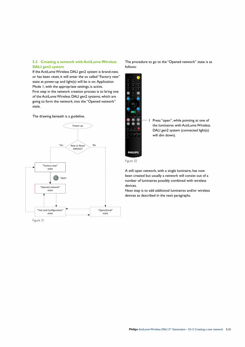
5.3 Creating a network with ActiLume Wireless DALI gen2 systemIf the ActiLume Wireless DALI gen2 system is brand-new, or has been reset, it will enter the so called “Factory new” state at power-up and light(s) will be is on. Application Mode 1, with the appropriate settings, is active.First step in the network creation process is to bring one of the ActiLume Wireless DALI gen2 systems, which are going to form the network, into the “Opened network” state.
The drawing beneath is a guideline.
Figure 31
The procedure to go to the “Opened network” state is as follows:
1 Press “open”, while pointing at one of the luminaires with ActiLume Wireless DALI gen2 system (connected light(s) will dim down).
Figure 32
A still open network, with a single luminaire, has now been created but usually a network will consist out of a number of luminaires possibly combined with wireless devices. Next step is to add additional luminaires and/or wireless devices as described in the next paragraphs.
Power-up
New or ResetAWDG2?
“Factory new”state
“Operational”state
Yes No
“Test and Configuration”state
“Opened network”state
Open

Philips ActiLume Wireless DALI 2nd Generation - Ch 5 Creating a new network5-22
70% G
min
100 h
group
link? mode?
mode
power up background IR group reset
add
pirdelay daylight RF channel
0
0
o�
save
on
I/ II
O)))
A-G
zone
%on/o�
87 950% E40% D 60% F
54 620% B10% A
II
30% C
PLBMS W/C
21 3
test
con�g
scene
5.4 Adding luminaires to a new networkMake sure that the procedure of paragraph 5.3, bringing one luminaire with ActiLume Wireless DALI gen2 system into the “Opened network” state, has been performed before starting to add luminaires to the network.
The luminaires, equipped with the ActiLume Wireless DALI gen2 system, that are to be added to the network need to be connected to the mains, be switched on and be in the “Factory new” state (either new or reset).
The drawing beneath is a guideline.
Figure 33
To add luminaires to the network follow this procedure:
1 Press “add” while pointing at a luminaire that is to become part of the network (luminaire will dim down)
2 Repeat step 1) while pointing at the following luminaires until all are added to the network (each time a luminaire is added it will dim down).
Figure 34
It is good practice to create the network, starting in the center of the area, working in a circular manner outwards, until all luminaires are added. By using this method a strong and stable network is created.
Next step is to close the network, bringing it into the “Test and Configuration” state, as described in the next paragraph.
Power-up
New or ResetAWDG2?
“Factory new”state
“Operational”state
Yes No
“Test and Configuration”state
“Opened network”state

Philips ActiLume Wireless DALI 2nd Generation - Ch 5 Creating a new network 5-23
70% G
min
100 h
group
link? mode?
mode
power up background IR group reset
add
pirdelay daylight RF channel
0
0
o�
save
on
I/ II
O)))
A-G
zone
%on/o�
87 950% E40% D 60% F
54 620% B10% A
II
30% C
PLBMS W/C
21 3
test
con�g
scene
5.5 Closing a networkOnce all luminaires, with ActiLume Wireless DALI gen2 system, or wireless Philips ZigBee devices have been added to the network it has to be closed.
The drawing beneath is a guideline.
Figure 35
To close the network, follow this procedure:
1 Press “close” while pointing to one of the luminaires (all luminaires will now dim up).
The network is now in “Test and Configuration” state.
To test the network, follow the procedure:2 Press “off” while pointing to a luminaire All luminaires in the network will
switch off.
3 Press “on” all luminaires will switch on.
Figure 36
Testing the network can also be done by pressing the “ ” and/or “ ” button, all luminaires will dim downand dim up.
Lock the network, if configuration (refer to chapter 6) and testing is completed, according to the next paragraph.
Power-up
New or ResetAWDG2?
“Factory new”state
“Operational”state
Yes No
“Test and Configuration”state
“Opened network”state
Close

Philips ActiLume Wireless DALI 2nd Generation - Ch 5 Creating a new network5-24
70% G
min
100 h
group
link? mode?
mode
power up background IR group reset
add
pirdelay daylight RF channel
0
0
o�
save
on
I/ II
O)))
A-G
zone
%on/o�
87 950% E40% D 60% F
54 620% B10% A
II
30% C
PLBMS W/C
21 3
test
con�g
scene
5.6 Locking a networkOnce finished adding luminaires, wireless devices and adapting settings the last step is to lock the network.
The drawing beneath is a guideline.
Figure 37
The procedure to lock the network is as follows:
1 Press “lock”, red LED on the IRT9090 will flash.
2 Press “send” while pointing the remote at one of the luminaires.
Figure 38
During transmission the red LED on the IRT9090 will flash. After transmission connected light(s) will flash twice to confirm that the command is correctly received and executed.
With this action the system goes into the “Operational” state and is ready for daily use.
Power-up
New or ResetAWDG2?
“Factory new”state
“Operational”state
Yes No
“Test and Configuration”state
“Opened network”state
Lock Send

Philips ActiLume Wireless DALI 2nd Generation - Ch 5 Creating a new network 5-25
70% G
min
100 h
group
link? mode?
mode
power up background IR group reset
add
pirdelay daylight RF channel
0
0
o�
save
on
I/ II
O)))
A-G
zone
%on/o�
87 950% E40% D 60% F
54 620% B10% A
II
30% C
PLBMS W/C
21 3
test
con�g
scene
5.7 Unlocking a networkIn some cases there is a need to make a modification to an existing network (which is in the “Operational” state), for example to adapt a setting. In that case the network needs to be brought into the “Test and Configuration” state.
The drawing beneath is a guideline.
Figure 39
To unlock the network follow this procedure:
1 Press “unlock”, red LED on IRT9090 will flash
2 Press “send”, while pointing at a luminaire with ActiLume Wireless DALI gen2 system.
Figure 40
During transmission the red LED on the IRT9090 will flash. After transmission connected light(s) will flash twice to confirm that the command is correctly received and executed.
Power-up
New or ResetAWDG2?
“Factory new”state
“Operational”state
Yes No
“Test and Configuration”state
“Opened network”state
UnlockSend

Philips ActiLume Wireless DALI 2nd Generation - Ch 5 Creating a new network5-26
70% G
min
100 h
group
link? mode?
mode
power up background IR group reset
add
pirdelay daylight RF channel
0
0
o�
save
on
I/ II
O)))
A-G
zone
%on/o�
87 950% E40% D 60% F
54 620% B10% A
II
30% C
PLBMS W/C
21 3
test
con�g
scene
70% G
min
100 h
group
link? mode?
mode
power up background IR group reset
add
pirdelay daylight RF channel
0
0
o�
save
on
I/ II
O)))
A-G
zone
%on/o�
87 950% E40% D 60% F
54 620% B10% A
II
30% C
PLBMS W/C
21 3
test
con�g
scene
5.8 Removing a luminaire from a networkTo remove luminaires, equipped with the ActiLume Wireless DALI gen2 system from a network, the network needs to be in the “Test and Configuration” state (refer to paragraph 5.7). The actual action is resetting the luminaire, that needs to be removed, to the “Factory new” state.
Use the following sequence:
1 Press “reset”, red LED on IRT9090 will start to flash
2 Press “send” while pointing the remote towards the luminaire that needs to be removed
The connected light(s) will switch off and after about 30s. switch on.
Figure 41
Lock the network, if configuration (refer to chapter 6) and testing is completed, according to paragraph 5.6.
5.9 Creating zones in a networkOnce a network has been created it can be divided into zones with different settings and behavior.A maximum of 32 zones can be created within 1 network.
Ensure that the system is in the “Test and Configuration” state (refer to paragraph 5.7).
Use the following sequence:
1 Press “zone”, while pointing the remote at a luminaire (luminaire will dim up other luminaires will dim down).
2 Press “add”, while pointing at the next luminaire that is to be placed in the same zone. (luminaire will dim up)
To create more zones repeat the first twosteps from this procedure.
3 Press “close” to end zone creationFigure 42
The network is now in “Test and Configuration” state
To test the zone’s follow, the procedure:4 Press “►”, while pointing to a luminaire
Lights in a zone will dim up and in the other zone(s) dim down
Lock the network, if configuration (refer to chapter 6) and testing is completed, according to paragraph 5.6.
NoteThe reset will:4Bring the ActiLume Wireless DALI gen2 system
into application Mode 1.4For Modes 1 through 11, application settings
are reset back to the factory defaults (OOTB settings).
4For Modes 12 through 15, application settings are maintained.
4Clear all wireless settings, meaning the ActiLume Wireless DALI gen2 will no longer be part of a network.
NoteA luminaire can only be part of one zone.
Figure 42

Philips ActiLume Wireless DALI 2nd Generation - Ch 5 Creating a new network 5-27
5.10 Removing a luminaire from a zoneWhen desired a luminaire with ActiLume Wireless DALI gen2 system can be removed from a zone. Ensure that the network is in the “Test and Configuration” state (refer to paragraph 5.7).
Use the following sequence:
1 Press “zone” while pointing the remote at the luminaire that needs to be removed (all luminaires in the zone will dim up and all luminaires outside the zone will dim down).
2 Press “0” (zero) while still pointing to the luminaire (luminaire will dim down).
To remove more luminaires from the same zone repeat step 2) (for each removal step, point to a different luminaire).
When a luminaire, from a different zone, need to be removed repeat steps 1) and 2).
3 Press “close” to end removing luminaires from zone(s).
Figure 43
Lock the network, if configuration (refer to chapter 6) and testing is completed, according to paragraph 5.6.
70% G
min
100 h
group
link? mode?
mode
power up background IR group reset
add
pirdelay daylight RF channel
0
0
o�
save
on
I/ II
O)))
A-G
zone
%on/o�
87 950% E40% D 60% F
54 620% B10% A
II
30% C
PLBMS W/C
21 3
test
con�g
scene
NoteThe network stays in the “Test and Configuration” state.

Philips ActiLume Wireless DALI 2nd Generation - Ch 5 Creating a new network5-28
5.11 Adding wireless devices to an existing networkOnce a network is created and is operational there is always the possibility to add Philips ZigBee wireless devices such as; sensors from the OccuSwitch Wireless (OSW) family, switches, scene selectors and addition luminaires equipped with the ActiLume Wireless DALI gen2 system (adding luminaires with ActiLume Wireless DALI gen2 system is covered in paragraph 5.4). The procedure to add devices is described in the following sub-paragraphs. Important to understand is that wireless sensors, switches and scene selectors always function at network level so they cannot be added to a zone and there is a limitation on the amount and type of devices that can be added to a network (refer to paragraph 2.5).The system has to be brought into the “Opened network” state coming from the “Test and Configuration” state. To bring the system in the “Test and Configuration” state it has to be unlocked as described in paragraph 5.7.
The drawing beneath is a guideline.
Figure 44
The procedure to go to the “Opened network” state is as follows:
1 Press “open”, while pointing at one of the luminaires with ActiLume Wireless DALI gen2 system. This will bring that system into the “Opened network” state.
Figure 45
All connected light(s) will dim down.
During transmission the red LED on the IRT9090 will flash.
70% G
min
100 h
group
link? mode?
mode
power up background IR group reset
add
pirdelay daylight RF channel
0
0
o�
save
on
I/ II
O)))
A-G
zone
%on/o�
87 950% E40% D 60% F
54 620% B10% A
II
30% C
PLBMS W/C
21 3
test
con�g
scene
Power-up
New or ResetAWDG2?
“Factory new”state
“Operational”state
Yes No
“Test and Configuration”state
“Opened network”state
Open

Philips ActiLume Wireless DALI 2nd Generation - Ch 5 Creating a new network 5-29
5.11.1 Adding a sensor, from the OSW family, to a networkTo add an OSW sensor, whether it is the LRM1763, LRM1765, LRM1770 or LRM1775, the network has to be in the “Opened network” state (refer to paragraph 5.11).
Figure 46
For all types use the following sequence:Hold the OSW device in the proximity of a luminaire equipped with ActiLume Wireless DALI gen2 system.1) Briefly press the “Link” button
The sensor starts a search cycle for an open network. The cycle is indicated by the flashing LED on the sensor. When the LED has turned green, before switching off, this indicates that the sensor is successfully added to the network.If the LED has turned red before switching off, this indicates that it has not been added to the network. In that case reposition the sensor and repeat step 1)
Add additional sensors, taking the limitation as mentioned in paragraph 2.5 into account.
Close the network (refer to paragraph 5.5).
The network enters the “Test and Configuration” state and the link between the OSW device, and the rest of the network, can be tested by briefly pressing the “Link” button. The luminaires in the network will switch On or Off depending on their previous state.
Lock the network, if configuration (refer to chapter 6) and testing is completed, according to paragraph 5.6.
To test the function, trigger the PIR sensor by movement (luminaries will switch on if they were off), then abandon the area. After the timers have expired the luminaries will switch off.
5.11.2 Removing (resetting) a OSW sensor from a networkTo remove a OSW sensor from the network it is not relevant in which state the network is.
Follow this procedure:
Figure 47
1 Press and hold the “Link” button until LED has turned green then release the button
This action resets the OSW device and it is no longer part of a network.
!ImportantMake sure to set the hold-time dial to the minimum (refer to applicable installation instruction).
PHILIPS
yellow green
yellow red
PHILIPS
red8x
off
yellow greenred

Philips ActiLume Wireless DALI 2nd Generation - Ch 5 Creating a new network5-30
5.11.3 Adding a UID8410 device to a networkTo add an UID8410 Wireless Scene Control the network has to be in the “Opened network” state (refer to paragraph 5.11). If it is uncertain whether the UID8410 is brand-new then perform a reset according to procedure paragraph 5.11.4 prior to trying to add the UID8410 to a network.
Use the following sequence:
Figure 48
1 Hold the UID8410 in the proximity of a luminaire, with ActiLume Wireless DALI gen2 system, and simultaneously press and hold the buttons as indicated.
Once the LED’s (area indicated with an ellipse) on the UI flash and an audible signal is generated the buttons can be released.
If the LED in the center flashes and a buzzer like audible signal is generated, entering the “Menu network” state failed. In that case release the buttons and repeat step 1)
Figure 49
2 Briefly press ”•••” button, response is LED in the center flashes, the button related LED is continuously on and an audible signal is generated.
Figure 50
3 Briefly press ”I” button, if the UI joined the network the response is that the LED in the center goes off, LED under ”•••” button is continuously on and an audible signal is generated
If a buzzer like audible signal is generated the action to join the network has failed. Retry step 3) and if the action keeps on failing reset the UID8410 according to paragraph 5.11.4 (then restart the procedure at step 1)
Figure 51
4 Briefly press ”•” button, response of UI is LED’s will flash (area indicated with an ellipse) and an audible signal is generated.
Philips ActiLume Wireless DALI 2nd Generation - Ch 5 Creating a new network 5-31
Figure 52
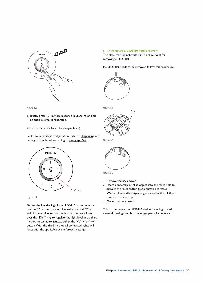
5) Briefly press ”0” button, response is LED’s go off and an audible signal is generated.
Close the network (refer to paragraph 5.5).
Lock the network, if configuration (refer to chapter 6) and testing is completed, according to paragraph 5.6.
Figure 53
To test the functioning of the UID8410 in the network use the “I” button to switch luminaires on and “0” to switch them off. A second method is to move a finger over the “Dim” ring to regulate the light level and a third method to test is to activate either the “•”, “••” or “•••” button. With the third method all connected lights will react with the applicable scene (preset) settings.
5.11.4 Removing a UID8410 from a networkThe state that the network is in is not relevant for removing a UID8410.
If a UID8410 needs to be removed follow this procedure:
Figure 54
Figure 55
Figure 56
1 Remove the back cover.2 Insert a paperclip, or alike object, into the reset hole to
activate the reset button (keep button depressed). Wait until an audible signal is generated by the UI, then
remove the paperclip.3 Mount the back cover.
This action resets the UID8410 device, including stored network settings, and it is no longer part of a network.
“dim” ring
1
3
2
+–
+–+
–

Philips ActiLume Wireless DALI 2nd Generation - Ch 5 Creating a new network5-32
5.11.5 Introduction to ZigBee Green Power (ZGP) devicesA ZigBee network and devices function in the 2.4GHz frequency band but within one channel of that frequency band. For the ActiLume Wireless DALI gen2 system channels 15, 20 and 25 are available. When creating a network it is not known which channel is used and when adding a ZGP device to a network these devices have to be linked to the same channel as the channel the network is operating in. The procedure for linking a ZGP device into a network is described in the following paragraphs.
5.11.6 Adding a UID8450 ZGP switch to a networkThe network has to be in the “Opened network” state (refer to paragraph 5.11).
Figure 57
If a UID8450 needs to be added to the network follow this procedure:1 Remove the switch cover from the device with a thin,
but wide, flat screwdriver (insert at the indicated point) while pressing the top button.
The inner part is now accessible, note the 4 markings on this part (0, 1, A and B).2 Simultaneously press and hold buttons A0 and “Top”
for approximately 10s.3 Release the buttons and wait for connected luminaires
to respond. If connected luminaires respond with flashing twice
then the UID8450 operates on the same channel as the network, in that case proceed to step 7).
4 If there was no response from the luminaires, press and hold buttons A1 and “Bottom” for approximately 10s.
5 Release the buttons and wait for connected luminaires to respond.
If connected luminaires respond with flashing twice then the UID8450 operates on the same channel as the network, in that case go to step 7).
6 When after releasing the buttons there was still no response from the luminaires, press and hold buttons B1 and “Bottom” for approximately 10s.
After releasing the buttons the luminaires will respond with flashing twice and the UID8450 device operates on the same channel as the network.
7 Close the network (refer to paragraph 5.5)8 Mount the switch cover (click in place).
Lock the network, if configuration (refer to chapter 6) and testing is completed, according to paragraph 5.6.
To test the functioning of the UID8450 briefly press the recessed section on the cover to switch luminaires on and press the lower section of the cover to switch the luminaires off. To test the dim function press and hold the recessed section to dim-up or press and hold the “lower” section to dim-down.
5.11.7 Adding a UID8451 ZGP switch to a networkThe network has to be in the “Opened network” state (refer to paragraph 5.11).
Figure 58
If a UID8451 needs to be added to the network follow this procedure:1 Remove the switch cover from the device with a thin,
but wide, flat screwdriver (insert at the indicated point) while pressing the top button.
The inner part is now accessible, note the 4 markings on this part (0, 1, A and B).2 Simultaneously press and hold buttons A0 and “Top”
for approximately 10s.
!Importantif the network channel needs to be changed (refer to paragraph 6.7), for example due to disturbances, the ZGP device(s) have to be relinked to the same channel that the network is using.
2
4 6 1
b
d f 1
A B
0
1
A B
0
1
2
4 6 1
b
d f 1
A B
0
1
A B
0
1
2
4 6 1
b
d f 1
A B
0
1
A B
0
1

Philips ActiLume Wireless DALI 2nd Generation - Ch 5 Creating a new network 5-33
3 Release the buttons and wait for connected luminaires to respond.
If connected luminaires respond with flashing twice then the UID8451 operates on the same channel as the network, in that case proceed to step 7).
4 If there was no response from the luminaires, press and hold buttons A1 and “Bottom” for approximately 10s.
5 Release the buttons and wait for connected luminaires to respond.
If connected luminaires respond with flashing twice then the UID8451 operates on the same channel as the network, in that case go to step 7).
6 When after releasing the buttons there was still no response from the luminaires, press and hold buttons B1 and “Bottom” for approximately 10s.
After releasing the buttons the luminaires will respond with flashing twice and the UID8451 device operates on the same channel as the network.
7 Close the network (refer to paragraph 5.5).8 Mount the switch cover (click in place).
Lock the network, if configuration (refer to chapter 6) and testing is completed, according to paragraph 5.6.
To test the functioning of the UID8451 briefly press the upper section on the cover to switch luminaires on and press the lower section of the cover to switch the luminaires off. To test the dim function press and hold the upper section to dim-up or press and hold the “lower” section to dim-down.
5.11.8 Adding a UID8460 ZGP scene selector to a networkThe network has to be in the “Opened network” state (refer to paragraph 5.11).
Figure 59
If a UID8460 needs to be added to the network follow this procedure:1 Press and hold button marked “1” for approximately
10s.2 Release the “1” button and wait for connected
luminaires to respond. If connected luminaires respond with flashing twice
then the UID8460 operates on the same channel as the network, in that case go to step 6).
3 If there was no response from the luminaires, press and hold button marked “•” (one dot) for approximately 10s.
4 Release the “•” button and wait for connected luminaires to respond.
If connected luminaires respond with flashing twice then the UID8460 operates on the same channel as the network, in that case go to step 6).
5 When after releasing the “•” button there was still no response from the luminaires, press and hold button marked “••” (two dots) for approximately 10s.
After releasing the “••” button the luminaires will respond with flashing twice and the UID8460 device operates on the same channel as the network.
6 Close the network (refer to paragraph 5.5).
Lock the network, if configuration (refer to chapter 6) and testing is completed, according to paragraph 5.6.
To test the functioning of the UID8460 briefly press the “1” button, this is a recall of “Scene 1” and connected luminaires will respond with the appropriate settings. Briefly press the “•” button, this is a recall of “Scene 2” with its settings. Briefly press the “••” button, to recall “Scene 3” with its settings. Finally briefly press the “O” button this will switch the luminaires off.
3 5
1
3 5
1
NoteDo not engage one of the buttons for more than a few seconds as this might lead to an unintended channel change.

Philips ActiLume Wireless DALI 2nd Generation - Ch 5 Creating a new network5-34
5.11.9 Adding a UID8461 ZGP scene selector to a networkThe network has to be in the “Opened network” state (refer to paragraph 5.11).
Figure 60
If a UID8461 needs to be added to the network follow this procedure:1 Press and hold button marked “1” for approximately
10s.2 Release the “1” button and wait for connected
luminaires to respond.If connected luminaires respond with flashing twice then the UID8461 operates on the same channel as the network, in that case go to step 6).3 If there was no response from the luminaires, press and
hold button marked “•” (one dot) for approximately 10s.
4 Release the “•” button and wait for connected luminaires to respond.
If connected luminaires respond with flashing twice then the UID8461 operates on the same channel as the network, in that case go to step 6).
5 When after releasing the “•” button there was still no response from the luminaires, press and hold button marked “••” (two dots) for approximately 10s.
After releasing the “••” button the luminaires will respond with flashing twice and the UID8461 device operates on the same channel as the network.
6 Close the network (refer to paragraph 5.5).
Lock the network, if configuration (refer to chapter 6) and testing is completed, according to paragraph 5.6.
To test the functioning of the UID8461 briefly press the “1” button, this is a recall of “Scene 1” and connected luminaires will respond with the appropriate settings. Briefly press the “•” button, this is a recall of “Scene 2” with its settings. Briefly press the “••” button, to recall “Scene 3” with its settings. Finally briefly press the “O” button that will switch the luminaires off.
3 5
1
3 5
1
NoteDo not engage one of the buttons for more than a few seconds as this might lead to an unintended channel change.

Philips ActiLume Wireless DALI 2nd Generation - Ch 6 Changing default settings (configuring) 6-35
During configuring connected lights will flash* as a confirmation that the programming sequence is executed by the ActiLume Wireless DALI gen2 system. If the lights were off when starting configuring the ActiLume Wireless DALI gen2 system, the system will always end with all lights on, except when the mode in which the ActiLume DALI gen2 is in, is based on the “manual on / auto off” principle. In that case the lights will always be turned off after the flashing.
Red LED
Send button
Figure 61
Various default settings of the ActiLume DALI gen2 can be changed by means of the IRT9090 remote control. In this chapter it will be explained how to make these changes. In the following paragraphs there will be references to the red LED and “send” button of which the location is indicated in the picture.
All changes mentioned in this chapter need to be made with the network in the “Test and Configuration” state (refer to paragraph 5.7).
* = If a configuration change is successfully executed connected luminaires will flash twice. When the configuration change fails the connected luminaires will flash four times.
Very important to understand is that when modifying settings there is a difference between;4Modifications that are applicable for all ActiLume
Wireless DALI gen2 systems within the network:4Application Mode4Scenes storing4RF channel change4Daylight Dependent Regulation (DDR) set-point4Automatic calibration of DDR set-point
4Modifications that are applicable for individual ActiLume Wireless DALI gen2 systems (luminaire):4Hold time4Power-up state4Enable/disable Passive Infra-Red (PIR) sensor4Select PIR sensitivity (high or low)4Select PIR behavior (influence on power-up state,
prolong time and background level)4Enable/disable Daylight sensor4Select Daylight sensor behavior (influence on DDR,
DDO and DDS)4Background level4IR group address4Enable/disable 100hr. burn-in4Reset to factory defaults (Modes 12 through 15
maintain their settings)
70% G
min
100 h
group
link? mode?
mode
power up background IR group reset
add
pirdelay daylight RF channel
0
0
o�
save
on
I/ II
O)))
A-G
zone
%on/o�
87 950% E40% D 60% F
54 620% B10% A
II
30% C
PLBMS W/C
21 3
test
con�g
scene
6 Changing default settings (configuring)
Generally speaking a number of default settings will have to be modified to suite the application that the
ActiLume Wireless DALI gen2 system(s) are going to be used in. This changing of settings is often referred to
as configuring.

Philips ActiLume Wireless DALI 2nd Generation - Ch 6 Changing default settings (configuring)6-36
6.1 Changing the application mode
The default active application mode is Mode 1 – Cell Office. To select a different application mode the network has to be in the “Test and Configuration” state (refer to paragraph 5.7).
If a different application mode needs to be selected, follow this procedure:
1 Press “mode”, red LED on remote will start to flash
2 Select the desired application mode: for Mode 1 press “1” or “0” followed by “1”, for Mode 14 press “1” followed by “4” and so on
3 Point the front of the remote to the multi-sensor, of the ActiLume Wireless DALI gen2 system, and press “send”
During transmission the red LED on the IRT9090 will flash. After transmission connected light(s) will flash twice to confirm that the command is correctly received and executed.
Lock the network, if configuration and testing is completed, according to paragraph 5.6.
6.2 Request active Mode
If there is uncertainty about the active mode that the ActiLume Wireless DALI gen2 system in a network is in, the active mode number can be requested. To execute this request the network has to be in the “Test and Configuration” state (refer to paragraph 5.7).
To request the active mode number, follow this procedure:
1 Press “mode ?”, while pointing the remote to the multi-sensor of a luminaire with ActiLume Wireless DALI gen2 system
Connected lights of that luminaire will first go for 2s. to minimum level followed by 2s. at maximum level (see figure 64).
Depending on the mode, ≤9, 10 or ≥11 the light pattern that follows differs (see figure 64-a, b or c respectively).
The connected lights will go back to their previous situation
During transmission the red LED on the IRT9090 will flash.
If there is uncertainty about whether all ActiLume Wireless DALI gen2 systems in the network are in the same mode the request has to be repeated for the other ActiLume Wireless DALI gen2 systems.
70% G
min
100 h
group
link? mode?
mode
power up background IR group reset
add
pirdelay daylight RF channel
0
0
o�
save
on
I/ II
O)))
A-G
zone
%on/o�
87 950% E40% D 60% F
54 620% B10% A
II
30% C
PLBMS W/C
21 3
test
con�g
scene
70% G
min
100 h
group
link? mode?
mode
power up background IR group reset
add
pirdelay daylight RF channel
0
0
o�
save
on
I/ II
O)))
A-G
zone
%on/o�
87 950% E40% D 60% F
54 620% B10% A
II
30% C
PLBMS W/C
21 3
test
con�g
scene
NoteChange is at network level. Note
Request is on individual ActiLume Wireless DALI gen2 system level.
Figure 62
Figure 63

Philips ActiLume Wireless DALI 2nd Generation - Ch 6 Changing default settings (configuring) 6-37
Figure 64
Lock the network, if configuration and testing is completed, according to paragraph 5.6.
NoteIf the 100 hour burn-in cycle is active the dim to minimum level, after the “mode?” command is received, will not be visible. To see the above pattern switch the 100 hour burn-in cycle temporarily off.
Pressmode?button
Min. level
Max. level
Single digitMode #
(Modes 1 through 9)
1s. at Min. level followed by 1s. at Max. level counts as 1(this example = mode 5)
2s.
2s.
2s.
State before request
State after request
=State
before request
a
State before request
Double digitMode #
(Modes 10)
Min. level
Max. level
2s.
Start of second digit(end of first digit)
1s. at Min. level followed by 1s. at Max. level counts as 1 2s. Off counts as 0 (zero)(this example = mode 10)
State after request
=State
before request
Pressmode?button
2s.2s.
2s.
2s.
2s. Off
b
State before request
Double digitMode #
(Modes 11 through 15)
Min. level
Max. level
2s.
Start of second digit(end of first digit)
1s. at Min. level followed by 1s. at Max. level counts as 1 (this example = mode 14)
State after request
=State
before request
Pressmode?button
2s.
2s.
2s.
2s.
2s.
c

Philips ActiLume Wireless DALI 2nd Generation - Ch 6 Changing default settings (configuring)6-38
6.3 Setting the background level
By default the background level is set to 10% or 20% depending on the active mode. To be able to make a configuration change the network has to be in the “Test and Configuration” state (refer to paragraph 5.7).
To modify the background level, follow this procedure:
1 Press background “%”
2 Press “0” for minimum “1” for 10% “2” for 20% “3” for 30% “4” for 40% “5” for 50% “6” for 60% “7” for 70%
3 Point the front of the remote to the multi-sensor and press “send”
During transmission the red LED on the IRT9090 will flash. After transmission connected light(s) will flash twice to confirm that the command is correctly received and executed.
Lock the network, if configuration and testing is completed, according to paragraph 5.6.
6.4 Changing Power-up-state
By default the power-up state depends on the active application mode. To be able to make a configuration change the network has to be in the “Test and Configuration” state (refer to paragraph 5.7).
To change the power-up state, follow this procedure:
1 Press power up “on/off”
2 Press either “on” or “off” “on” for power-up state on “off” for power-up state off
3 Point the front of the remote to the multi-sensor and press “send”
During transmission the red LED on the IRT9090 will flash. After transmission connected light(s) will flash twice to confirm that the command is correctly received and executed.
Lock the network, if configuration and testing is completed, according to paragraph 5.6.
70% G
min
100 h
group
link? mode?
mode
power up background IR group reset
add
pirdelay daylight RF channel
0
0
o�
save
on
I/ II
O)))
A-G
zone
%on/o�
87 950% E40% D 60% F
54 620% B10% A
II
30% C
PLBMS W/C
21 3
test
con�g
scene
70% G
min
100 h
group
link? mode?
mode
power up background IR group reset
add
pirdelay daylight RF channel
0
0
o�
save
on
I/ II
O)))
A-G
zone
%on/o�
87 950% E40% D 60% F
54 620% B10% A
II
30% C
PLBMS W/C
21 3
test
con�g
scene
Figure 65
NoteChange is on individual ActiLume Wireless DALI gen2 system level so, if needed, the procedure has to be repeated for other ActiLume Wireless DALI gen2 systems in the network.
NoteChange is on individual ActiLume Wireless DALI gen2 system level so, if needed, the procedure has to be repeated for other ActiLume Wireless DALI gen2 systems in the network.
Figure 66

Philips ActiLume Wireless DALI 2nd Generation - Ch 6 Changing default settings (configuring) 6-39
6.5 Setting the network IR group address
When using more than one network, in for example an open office with large area, with each an IR remote control it is very well possible that the remotes will have influence on more than one network. In order to prevent this, a different IR group address can be assigned to each network and IR remote. By default the IR group address of a network and remote is “A”. To be able to make a configuration change the network has to be in the “Test and Configuration” state (refer to paragraph 5.7).
To change the IR group address, follow this procedure:
1 Press IR group “A-G”
2 Select desired IR group address “1” for IR group A “2” for IR group B “3” for IR group C “4” for IR group D “5” for IR group E “6” for IR group F “7” for IR group G
3 Point the front of the remote to the multi-sensor and press “send”
During transmission the red LED on the IRT9090 will flash. After transmission connected light(s) will flash twice to confirm that the command is correctly received and executed.
Lock the network, if configuration and testing is completed, according to paragraph 5.6.
To test whether all ActiLume Wireless DALI gen2 systems, in the same network, are assigned to the same IR group address briefly press the control buttons (on/off) on the remote, which is going to be used for local control. Response is that all connected luminaires will switch on or off. Now set the IR group address dipswitches/rotary switch in the remote to another IR group address than previously selected. Once again activate the control buttons (on/off) and the response should be that none of the ActilLume Wireless DALI gen2 system(s) will react. In the remote set the dipswitches/rotary switch back to the IR group address setting that was initially chosen.
70% G
min
100 h
group
link? mode?
mode
power up background IR group reset
add
pirdelay daylight RF channel
0
0
o�
save
on
I/ II
O)))
A-G
zone
%on/o�
87 950% E40% D 60% F
54 620% B10% A
II
30% C
PLBMS W/C
21 3
test
con�g
scene
NotesChange is on one (1) ActiLume Wireless DALI gen2 system level so the procedure has to be repeated for all ActiLume Wireless DALI gen2 systems within the network.Local control such as switching on, off, dim-up and dim-down will be active across the complete network even if ActiLume Wireless DALI gen2 systems are not assigned to the same IR group address.
Figure 67
NotesIn order to have remote controls operate on the same IR group address as the network, the IR group address of the remote has to be modified. Usually changing the IR group address on the remote is achieved by means of dipswitches or a rotary switch which are located in the battery compartment (please refer to the datasheets of the relevant remote control).Changing the IR group address has no influence on the IRT9090 remote control used for configuration. This remote uses a broadcast signal which is accepted independently from the IR group address the ActiLume Wireless DALI gen2 system is assigned to.
NoteIf by mistake not all ActiLume Wireless DALI gen2 systems, within one (1) network, are assigned to the same IR group address then the result can be that the system reacts to remotes that are set to different IR group addresses and that were assigned to be used with different network(s).
NoteWait for at least 3s. after locking the network before operating the system with an IR remote.

Philips ActiLume Wireless DALI 2nd Generation - Ch 6 Changing default settings (configuring)6-40
6.6 Changing the RF channel
Nowadays many devices are active in the 2.4GHz frequency band, with a number of channels in that band, so it is imaginable that there is disturbance on the network that the ActiLume Wireless DALI gen2 controller(s) are in. Disturbance can for example be that not all luminaires will react when a light on or off command is send. ActiLume Wireless DALI gen2 controller(s) are able to operate in only one out of three channels, either channel 15, 20 or 25. Be aware that you cannot identify the channel the network is operating in. To be able to make a configuration change the network has to be in the “Test and Configuration” state (refer to paragraph 5.7).
To change the RF channel, follow this procedure:
1 Press “RF channel”, red LED on remote will flash
2 Select a two digit code either 15, 20 or 25, note the chosen code down
3 Press “send”
During transmission the red LED on the IRT9090 will flash. After transmission connected light(s) will flash twice to confirm that the command is correctly received and executed.
To test if the RF channel change was successful, follow the procedure:
4 Press “off”, while pointing to a luminaire. All luminaires in the network should switch off.
5 Press “on”, while pointing to a luminaire. All luminaires in the network should switch on.
If not all luminaires respond correctly, to the “off” or “on” command, repeat the RF channel change procedure (steps 1, 2 and 3) for those luminaires that did not react using the previously chosen RF channel.
Lock the network, if configuration and testing is completed, according to paragraph 5.6.
Test the network to check if it is no longer sensitive for disturbances. If there are still disturbances noticeable then repeat the procedure but choose one of the other two available channels.
70% G
min
100 h
group
link? mode?
mode
power up background IR group reset
add
pirdelay daylight RF channel
0
0
o�
save
on
I/ II
O)))
A-G
zone
%on/o�
87 950% E40% D 60% F
54 620% B10% A
II
30% C
PLBMS W/C
21 3
test
con�g
scene
NoteChange is at network level
Figure 68
NoteIf the network channel is changed the ZGP devices need to be relinked as they do not take over the new network channel automatically (refer to paragraph 5.11.6, 5.11.7, 5.11.8 or 5.11.9).

Philips ActiLume Wireless DALI 2nd Generation - Ch 6 Changing default settings (configuring) 6-41
6.7 Walk test
Correct operation of all movement detectors in the network can be checked by activating the “Walk test” functionality of the system and is used to check coverage of the network area for movement. To be able to perform this test the network has to be in the “Test and Configuration” state (refer to paragraph 5.7).
To activate the walk test function, follow this procedure:
1 Press “walk test”, all luminaires in the network will dim down if no movement is detected. If movement is detected connected luminaires will dim up.
During transmission the red LED on the IRT9090 will flash.
Lock the network, if configuration and testing is completed, according to paragraph 5.6.
6.8 100 hour burn-in
A number of fluorescent lamp manufacturers state that prior to normal use, fluorescent lamps should not be dimmed. First these lamps should be “burned in” for 100 hours in order to maintain light quality and lifetime also at low dimming level. In order to enable this, the ActiLume Wireless DALI gen2 system has the capability to activate the 100 hours burn-in period. During this period all connected lights are not dimmable. The ActiLume Wireless DALI gen2 system uses a burning hour counter based on the status of connected lights(s).It is possible to enable and disable the 100 hour burn-in period by means of the IRT9090 remote control. By default the 100 hour burn-in period is disabled.
The enable the burn-in period the network has to be in the “Test and Configuration” state (refer to paragraph 5.7).
To activate the burn-in period, follow this procedure:
1 Press “100 h”, connected light(s) will dim up.
If it is needed to disable the timer press the “100 h” button once again.
70% G
min
100 h
group
link? mode?
mode
power up background IR group reset
add
pirdelay daylight RF channel
0
0
o�
save
on
I/ II
O)))
A-G
zone
%on/o�
87 950% E40% D 60% F
54 620% B10% A
II
30% C
PLBMS W/C
21 3
test
con�g
scene
70% G
min
100 h
group
link? mode?
mode
power up background IR group reset
add
pirdelay daylight RF channel
0
0
o�
save
on
I/ II
O)))
A-G
zone
%on/o�
87 950% E40% D 60% F
54 620% B10% A
II
30% C
PLBMS W/C
21 3
test
con�g
scene
NoteWalk test is active on network level.
Figure 69
NoteSetting is on one (1) ActiLume Wireless DALI gen2 system level so the procedure has to be repeated for all ActiLume Wireless DALI gen2 systems in the network if needed.
Notes if OSW sensors are part of the network a red LED will flash when movement is detected. They will not activate any of the luminaires in the network.The “walk test” will automatically be deactivated after 10min. and an alternative way to end the test is to press the “walk test” button again.
Figure 70

Philips ActiLume Wireless DALI 2nd Generation - Ch 6 Changing default settings (configuring)6-42
During transmission the red LED on the IRT9090 will flash. After transmission connected light(s) will flash twice to confirm that the command is correctly received and executed.
Only during set point calibration and configuration, the 100 hour burn-in period, will temporarily be overridden.
Lock the network, if configuration and testing is completed, according to paragraph 5.6.
6.9 Disable the motion sensor (PIR)
Since motion detection is based on moving temperature spots it is possible that the sensor detects movement from for example airflow from an HVAC, heater or draft from an open window (see drawing), which has a different temperature compared to its surroundings. This can lead to unwanted triggering of the system and to prevent this undesired effect the motion sensor, which is of the Passive Infra-Red (PIR) type, can be disabled.
The system has to be in the “Test and Configuration” state (refer to paragraph 5.7).
To disable the motion sensor (PIR), follow this procedure:
1 Press “pir”, red LED on remote will flash
2 Press “off”, to disable the PIR sensor
3 Point the front of the remote to the multi-sensor and press “send”
During transmission the red LED on the IRT9090 will flash. After transmission connected light(s) will flash twice to confirm that the command is correctly received and executed.
If the motion detection function is switched off, the ActiLume Wireless DALI gen2 will as of that point in time only react to presence detected by other sensors if relevant for that ActiLume Wireless DALI gen2 system.
Whenever the PIR is disabled, it can be enabled by selecting “on” at step 2 of the procedure.
Lock the network, if configuration and testing is completed, according to paragraph 5.6.
70% G
min
100 h
group
link? mode?
mode
power up background IR group reset
add
pirdelay daylight RF channel
0
0
o�
save
on
I/ II
O)))
A-G
zone
%on/o�
87 950% E40% D 60% F
54 620% B10% A
II
30% C
PLBMS W/C
21 3
test
con�g
scene
NoteThe burn-in timer can only be reset with a complete ActiLume Wireless DALI gen2 system reset as described in paragraph 5.2 Be aware that when performing such a reset all configuration modifications, with the exception for changes for Modes 12 through 15, will be lost in which case re-configuration is required.
NoteSetting is on one (1) ActiLume Wireless DALI gen2 system level so the procedure has to be repeated for all ActiLume Wireless DALI gen2 systems in the network if needed.
Figure 71
Figure 72

Philips ActiLume Wireless DALI 2nd Generation - Ch 6 Changing default settings (configuring) 6-43
6.10 Selecting motion sensor (PIR) sensitivity
Since motion detection is based on moving temperature spots it is possible that the sensor detects movement from for example airflow from an HVAC unit, which has a different temperature compared to its surroundings, which can lead to false triggering of the system. If airflow triggers the sensor, it is possible to reduce its sensitivity to eliminate this effect. There are two settings available, high (default) or low sensitivity.The system has to be in the “Test and Configuration” state (refer to paragraph 5.7).
To modify the sensitivity of the motion sensor (PIR), follow this procedure:
1 Press “pir”, red LED on remote will flash
2 Press “1” for High sensitivity, “3” for Low sensitivity
3 Point the front of the remote to the multi-sensor and press “send”
During transmission the red LED on the IRT9090 will flash. After transmission connected light(s) will flash twice to confirm that the command is correctly received and executed.
If the PIR function is disabled, it can be enabled by selecting either “on” or one of the two sensitivity settings at step two of this procedure.
Lock the network, if configuration and testing is completed, according to paragraph 5.6.
70% G
min
100 h
group
link? mode?
mode
power up background IR group reset
add
pirdelay daylight RF channel
0
0
o�
save
on
I/ II
O)))
A-G
zone
%on/o�
87 950% E40% D 60% F
54 620% B10% A
II
30% C
PLBMS W/C
21 3
test
con�g
scene
NoteSetting is on one (1) ActiLume Wireless DALI gen2 system level so the procedure has to be repeated for all ActiLume Wireless DALI gen2 systems in the network if needed.
Figure 73

Philips ActiLume Wireless DALI 2nd Generation - Ch 6 Changing default settings (configuring)6-44
6.11 Selecting motion sensor (PIR) behavior
For some application areas, for example a pathway or a corridor, the reaction of the ActiLume Wireless DALI gen2 system on occupancy (whether local, elsewhere or ignore) can be selected. Selecting a different “occupancy mode” has influence on the power-up state, prolong time and background level.The system has to be in the “Test and Configuration” state (refer to paragraph 5.7).
To select different motion sensor (PIR) behavior, follow this procedure:
1 Press “pir”, red LED on remote will flash
2 Select number (see table)
3 Point the front of the remote to the multi-sensor and press “send”
During transmission the red LED on the IRT9090 will flash. After transmission connected light(s) will flash twice to confirm that the command is correctly received and executed.
70% G
min
100 h
group
link? mode?
mode
power up background IR group reset
add
pirdelay daylight RF channel
0
0
o�
save
on
I/ II
O)))
A-G
zone
%on/o�
87 950% E40% D 60% F
54 620% B10% A
II
30% C
PLBMS W/C
21 3
test
con�g
scene
Occupancy Mode Behavior Power up state Prolong Time Background Level 10 Normal mode (default) Set to active Set to active Set to active application setting application setting application setting 11 Path of Egress Set to On Set to Infinitive Set to active application setting 12 Always On Set to On Set to Infinitive Set to 100%
Table 6
Lock the network, if configuration and testing is completed, according to paragraph 5.6.
NoteSetting is on one (1) ActiLume Wireless DALI gen2 system level so the procedure has to be repeated for other ActiLume Wireless DALI gen2 systems in the network if needed.
Figure 74

Philips ActiLume Wireless DALI 2nd Generation - Ch 6 Changing default settings (configuring) 6-45
6.12 Selecting daylight sensor behavior
The behavior of the daylight sensor can be selected (including being enabled or disabled) if the used application or situation requires this. Selecting different daylight sensor behavior has influence on DDR, DDO and DDS so bear this in mind in relation to the Mode the ActiLume Wireless DALI gen2 system is being used in.The system has to be in the “Test and Configuration” state (refer to paragraph 5.7).
To select different daylight sensing behavior, follow this procedure:
1 Press “daylight”, red LED on remote will flash
2 Select number (see table)
3 Point the front of the remote to the multi-sensor and press “send”
During transmission the red LED on the IRT9090 will flash. After transmission connected light(s) will flash twice to confirm that the command is correctly received and executed.
70% G
min
100 h
group
link? mode?
mode
power up background IR group reset
add
pirdelay daylight RF channel
0
0
o�
save
on
I/ II
O)))
A-G
zone
%on/o�
87 950% E40% D 60% F
54 620% B10% A
II
30% C
PLBMS W/C
21 3
test
con�g
scene
Daylight Mode Behavior Daylight Daylight Daylight Dependent Dependent Dependent Override Switching Regulation 1 No reaction to daylight Disabled Disabled Disabled 2 Enable Daylight Dependent Regulation Disabled Disabled Enabled 3 Enable Daylight Dependent Regulation and Daylight Switching Disabled Enabled Enabled 4 Enable Daylight Dependent Regulation and Daylight Override Enabled Disabled Enabled 5 Enable Daylight Dependent Regulation, Daylight Override and Daylight Switching Enabled Enabled Enabled
Table 7
Lock the network, if configuration and testing is completed, according to paragraph 5.6.
Figure 75
NoteSetting is on one (1) ActiLume Wireless DALI gen2 system level so the procedure has to be repeated for all ActiLume Wireless DALI gen2 systems in the network if needed.

Philips ActiLume Wireless DALI 2nd Generation - Ch 6 Changing default settings (configuring)6-46
6.13 Change hold time
The hold time, this is the time that connected light(s) are still being regulated although the area is vacated, and can be set in minutes between 0.5 and 35min.The system has to be in the “Test and Configuration” state (refer to paragraph 5.7).
To select a different hold time, follow this procedure:
1 Press “delay”, red LED on remote will flash
2 Select delay time in minutes select 0 (zero) for 0.5min select 90 for 1.5min, all other values
in minutes.
3 Point the front of the remote to the multi-sensor and press “send”
During transmission the red LED on the IRT9090 will flash. After transmission connected light(s) will flash twice to confirm that the command is correctly received and executed.
Lock the network, if configuration and testing is completed, according to paragraph 5.6.
6.14 Automatic DDR set-point calibration
During system installation the light level in the area, that is formed with luminaires equipped with ActiLume Wireless DALI gen2 systems, should be checked against the light plan that the designer has created. It is possible to (re)calibrate ActiLume Wireless DALI gen2 systems in a network if for example new or additional office furniture is placed.During (re)calibration a number of things have to be considered, refer to paragraph 6.20, as they all have influence on the outcome of the calibration.Very important is to have the area darkened (curtains and/or blinds closed) so the amount of daylight ingress is minimal. If there is no possibility to darken the area then consider performing this calibration at nighttime.The system has to be in the “Test and Configuration” state (refer to paragraph 5.7).
To calibrate the light level set-point, follow this procedure:
1 Press “daylight”, red LED on remote will flash
2 Press “save”, while pointing to one of the ActiLume Wireless DALI gen2 systems in the network.
DDR set-point calibration will start and all luminaires will switch off (all sensor(s) will measure the amount of light = LMIN). Lights will switch on (all sensor(s) will measure again = LMAX)
70% G
min
100 h
group
link? mode?
mode
power up background IR group reset
add
pirdelay daylight RF channel
0
0
o�
save
on
I/ II
O)))
A-G
zone
%on/o�
87 950% E40% D 60% F
54 620% B10% A
II
30% C
PLBMS W/C
21 3
test
con�g
scene
70% G
min
100 h
group
link? mode?
mode
power up background IR group reset
add
pirdelay daylight RF channel
0
0
o�
save
on
I/ II
O)))
A-G
zone
%on/o�
87 950% E40% D 60% F
54 620% B10% A
II
30% C
PLBMS W/C
21 3
test
con�g
scene
Figure 76
NoteThis setting is on one (1) ActiLume Wireless DALI gen2 system level so the procedure has to be repeated for all ActiLume Wireless DALI gen2 systems in the network.
NoteThe DDR set-point calibration is active on network level.
Figure 77

Philips ActiLume Wireless DALI 2nd Generation - Ch 6 Changing default settings (configuring) 6-47
The new DDR set-point(s) will be the calculated result from LMAX - LMIN and is stored in the ActiLume Wireless DALI gen2 systems. The DDR set-point(s) are multiplied by the set-point correction factor (also referred to as set-point adjustment factor) of 88% resulting in a new light level regulation point. For additional information on the set-point correction factor refer to paragraph 6.15.
Example: LMIN =10 lux and LMAX = 510 lux (lux level values at
task surface) LMAX - LMIN = 500 lux (new daylight set-point) Light level regulation point = 440 lux (daylight set-point
multiplied by the set-point correction factor)
Lock the network, if configuration and testing is completed, according to paragraph 5.6.
6.15 Selecting a set-point correction factorIf, after having executed the set-point calibration according to paragraph 6.14, the overall light level is either too high or low this can be adapted, in three discrete steps, by selecting a different set-point correction factor. One step to increase and two steps the decrease the light level.The system has to be in the “Test and Configuration” state (refer to paragraph 5.7).
To select a set-point correction factor, follow this procedure:
1 Press “daylight”, red LED on remote will flash
2 Press either the “▲” (increase) or “▼” (decrease) button to select a different set-point correction factor (default correction factor is 88%). Each step is a correction factor change of 11%.
All connected luminaires will dim-up or down and if required repeat this step taking the limits into account (99% = maximum and 66% = minimum correction factor).
3 Press “send”, while pointing to one of the ActiLume Wireless DALI gen2 systems in the network.
If for example the daylight set-point is 500 lux and the correction factor was decreased by two steps to 66% then the light level regulation point will be 330 lux.
Lock the network, if configuration and testing is completed, according to paragraph 5.6.
70% G
min
100 h
group
link? mode?
mode
power up background IR group reset
add
pirdelay daylight RF channel
0
0
o�
save
on
I/ II
O)))
A-G
zone
%on/o�
87 950% E40% D 60% F
54 620% B10% A
II
30% C
PLBMS W/C
21 3
test
con�g
scene
NoteThe selected set-point correction factor is active on network level.
Figure 78

Philips ActiLume Wireless DALI 2nd Generation - Ch 6 Changing default settings (configuring)6-48
6.16 Manual DDR set-point calibration (network level)
The light level of an area, formed by ActiLume Wireless DALI gen2 systems in a network, can be modified in discrete steps to accommodate the desired situation.The system has to be in the “Test and Configuration” state (refer to paragraph 5.7).
To save the light level, follow this procedure:
1 Press either “▲” or “▼”, while pointing to one of the ActiLume Wireless DALI gen2 system luminaires in the network, to change the light level (red LED flashes during press action)
2 Press “save”, the light level is stored as a new set-point in all ActiLume Wireless DALI gen2 system(s) and the red LED on the remote flashes during transmission
All connected luminaires will flash twice to confirm that the command is correctly received and executed.The light level set-point is directly used as light level regulation point so no set-point correction factor is applied.
Lock the network, if configuration and testing is completed, according to paragraph 5.6.
6.17 Manual DDR set-point calibration (luminaire level)
The light level of one (1) luminaire, with ActiLume Wireless DALI gen2 system, can be modified in discrete steps to accommodate the desired situation.The system has to be in the “Operational” state (refer to paragraph 5.6).
To save the light level, follow this procedure:
3 Press either “▲” or “▼”, while pointing towards the ActiLume Wireless DALI gen2 system luminaire, to change the light level (red LED flashes during press action)
4 Press “save”, the light level is stored as a new set-point in the ActiLume Wireless DALI gen2 system and the red LED on the remote flashes during transmission
The connected luminaire will flash twice to confirm that the command is correctly received and executed.The light level set-point is directly used as light level regulation point so no set-point correction factor is applied.
70% G
min
100 h
group
link? mode?
mode
power up background IR group reset
add
pirdelay daylight RF channel
0
0
o�
save
on
I/ II
O)))
A-G
zone
%on/o�
87 950% E40% D 60% F
54 620% B10% A
II
30% C
PLBMS W/C
21 3
test
con�g
scene
70% G
min
100 h
group
link? mode?
mode
power up background IR group reset
add
pirdelay daylight RF channel
0
0
o�
save
on
I/ II
O)))
A-G
zone
%on/o�
87 950% E40% D 60% F
54 620% B10% A
II
30% C
PLBMS W/C
21 3
test
con�g
scene
Figure 79 Figure 80
NoteThis saving light level setting is active on luminaire level.
NoteThis saving light level setting is active on network level.
NoteLuminaires that have the daylight sensor disabled (or luminaires without a daylight sensor) will react upon motion in the network by dimming to a fixed light level. This light level is set during the manual DDR set-point calibration procedure.

Philips ActiLume Wireless DALI 2nd Generation - Ch 6 Changing default settings (configuring) 6-49
6.18 Introduction to scenes
The ActiLume Wireless DALI gen2 system supports 16 presets/scenes. Four scenes are predefined but can be modified by the user.Scene 1 is referred to as “Auto” with light control behavior according to the application setting (Daylight Dependent Regulation (DDR) is active). Scene 2 through 4 must be actively selected, refer to following paragraphs on storing and recall, and have different light level settings. The light level transition time, when switching between scenes, is fixed at 700ms.A summary of the 4 default scene settings is shown in the table below.
Scene # Status Light level Transition time 1 Auto regulated n.a. 2 On 20% 700ms. 3 On 40% 700ms. 4 On 80% 700ms.
Table 8
6.18.1 Storing scenes with IRT9090The ActiLume Wireless DALI gen2 system has the possibility to store up to 16 scenes whereby a scene is defined as a desired light level. Usually a scene requires a new light level that can be set, by either using the Touch and Dim (wired connection) functionality of the ActiLume Wireless DALI gen2 system or by means of an IR or RF remote, before actually storing it.The system has to be in the “Operational” state (refer to paragraph 5.6).
First set the desired light level using the “▲”, “▼”, “On “ or “Off” button on the remote.
To store a scene, follow this procedure:
1 Press “scene”, red LED on remote will flash
2 Select a scene number (1-16)
3 Point the front of the remote to the multi-sensor and press “save”
The light level, previously set, is stored in all ActiLume Wireless DALI gen2 systems. The system is now in manual override meaning that all luminaires will be set to the fixed (scene) light level.Please note that there is no response from the system with respect to connected lights flashing as a confirmation that the new scene value is received and stored.
70% G
min
100 h
group
link? mode?
mode
power up background IR group reset
add
pirdelay daylight RF channel
0
0
o�
save
on
I/ II
O)))
A-G
zone
%on/o�
87 950% E40% D 60% F
54 620% B10% A
II
30% C
PLBMS W/C
21 3
test
con�g
scene
!WarningSince Scene 1 is used for Daylight Dependent Regulation it is strongly advised NOT to program any value into Scene 1. If Scene 1 is programmed it is not possible to activate DDR. The only way to regain DDR is to reset the ActiLume Wireless DALI gen2.
NoteStoring a scene is active on network level.
Figure 81
!WarningSince Scene 1 is used for Daylight Dependent Regulation it is strongly advised NOT to program any value into Scene 1. If Scene 1 is programmed it will become a fixed light level and DDR is disabled. The only way to regain DDR is to either use the On button on the remote or to reset the ActiLume Wireless DALI gen2.

Philips ActiLume Wireless DALI 2nd Generation - Ch 6 Changing default settings (configuring)6-50
6.18.2 Storing scenes with UID8410The ActiLume Wireless DALI gen2 system has the possibility to store up to 16 scenes whereby a scene is defined as a desired light level. However please note that when using the UID8410 it is only possible to store 3 scenes. Usually a scene requires a new light level that can be set, by either using the Touch and Dim (wired connection) functionality of the ActiLume Wireless DALI gen2 system or by means of an IR or RF remote, before actually storing it.The system has to be in the “Operational” state (refer to paragraph 5.6).
First set the desired light level using either the dim-ring, 1 or 0 button on the UID8410.
To store a scene, follow this procedure:
1 Press and hold one of the three scene buttons (• is Scene 1, •• is Scene 2 and ••• is Scene 3), the related scene button is illuminated, until you hear three short beeps.
The light level, that was previously set, is stored in all ActiLume Wireless DALI gen2 systems. The system is now in manual override meaning that all luminaires will be set to the fixed (scene) light level.Please note that there is no response from the system with respect to connected lights flashing as a confirmation that the new scene value is received and stored.
6.18.3 Scene recall with IRT9090Stored scenes can be recalled with the remotes IRT9090, UID8410, IRT8030, IRT8050, UID8510, UID8460 and UID8461. With IRT9090 all 16 scenes, out of 16 that can be stored in ActiLume Wireless DALI gen2 systems, can be recalled.The system has to be in the “Operational” state (refer to paragraph 5.6).
To recall a scene, follow this procedure:
1 Press “scene”, red LED on remote will flash
2 Select a scene number (1-16)
3 Point the front of the remote to the multi sensor and press “send”
Response of all connected luminaires is that they will change their light level, related to the selected scene number, setting.
70% G
min
100 h
group
link? mode?
mode
power up background IR group reset
add
pirdelay daylight RF channel
0
0
o�
save
on
I/ II
O)))
A-G
zone
%on/o�
87 950% E40% D 60% F
54 620% B10% A
II
30% C
PLBMS W/C
21 3
test
con�g
scene
!ImportantSince Scene 1 is used for Daylight Dependent Regulation it is strongly advised NOT to program any value into Scene 1. If Scene 1 is programmed it will become a fixed light level and DDR is disabled. The only way to regain DDR is to either use the On button on the remote or to reset the ActiLume Wireless DALI gen2.
NoteStoring a scene is active on network level and the UID8410 has to be part of the network.
NotePressing one of the three scene buttons until all three buttons are illuminated (three beeps are heard during the cycle), will reset the ActiLume Wireless DALI gen2 systems scene settings to defaults.
NoteA scene recall is active on network level.
!ImportantActivate one of the motion sensors in the network so that luminaries are on
Figure 83
Figure 82

Philips ActiLume Wireless DALI 2nd Generation - Ch 6 Changing default settings (configuring) 6-51
6.18.4 Scene recall with UID8410Stored scenes can be recalled with the remotes IRT9090, UID8410, IRT8030, IRT8050, UID8510, UID8460 and UID8461. With UID8410 only the first 3 scenes, out of 16 that can be stored in ActiLume Wireless DALI gen2 systems, can be recalled.The system has to be in the “Operational” state (refer to paragraph 5.6).
To recall a scene, follow this procedure:
1 Briefly press one of the three scene buttons, the related scene button is illuminated and a short single beep is generated.
Figure 84
Response of all connected luminaires is that they switch on with the light level related to the scene number.
6.18.5 Scene recall with IRT8030Stored scenes can be recalled with the remotes IRT9090, UID8410, IRT8030, IRT8050, UID8510, UID8460 and UID8461. With IRT8030 only the first 4 scenes, out of 16 that can be stored in ActiLume Wireless DALI gen2 systems, can be recalled.The system has to be in the “Operational” state (refer to paragraph 5.6).
To recall a scene, follow the procedure:
1 Briefly press one of the four scene buttons.
Scene 1 Scene 2 Scene 3 Scene 4
Figure 85
Response of all connected luminaires is that they will change their light level, related to the scene number, setting.
NoteA scene recall is active on network level and the UID8410 has to be part of the network.
NotesScene recall with the IRT8030 remote only works correctly when the network and remote are assigned to the same IR group address (IR group address default, for both network and remote, is A). To set the network IR group address, refer to paragraph 6.5). To set the IRT8030 remote IR group address, refer to its datasheet.A scene recall is active on network level.
!ImportantActivate one of the motion sensors in the network so that luminaries are on.

Philips ActiLume Wireless DALI 2nd Generation - Ch 6 Changing default settings (configuring)6-52
6.18.6 Scene recall with IRT8050Stored scenes can be recalled with the remotes IRT9090, UID8410, IRT8030, IRT8050, UID8510, UID8460 and UID8461. With IRT8050 only the first 4 scenes, out of 16 that can be stored in ActiLume Wireless DALI gen2 systems, can be recalled.The system has to be in the “Operational” state (refer to paragraph 5.6).
The buttons on the IRT8050 have a “multi-touch” function, meaning that when pressing the buttons more than once, with a time interval of < 0.5 seconds between each press action, a different function will be active.
To recall a scene, follow the procedure:
1 Briefly press the right hand button twice, this will recall scene 2.
Figure 86
Response of all connected luminaires is that they will change their light level, related to the scene 2 setting.
Briefly pressing the right hand button once will recall scene 1, pressing three times will recall scene 3 and pressing four times will recall scene 4. A press action on the left hand button will switch the luminaires off.
NotesScene recall with the IRT8050 remote only works correctly when the network and remote are assigned to the same IR group address (IR group address default, for both network and remote, is A). To set the network IR group address, refer to paragraph 6.5). To set the IRT8050 remote IR group address, refer to its datasheet.Make sure that dipswitches, which can be found in the battery compartment, 4, 6 and 8 are set to On and dipswitches 5 and 7 are set to Off (refer to the datasheet). A scene recall is active on network level.
NotesThe IRT8050 can also be used for normal On/Off and dimming but in that case the dipswitches 4 through 8 must be set to Off. The left hand button will function as an Off switch, when briefly pressed, and dim-down when keeping the button depressed. The right hand button functions as On, when briefly pressed, and dim-up when keeping the button depressed. The IRT8050 cannot be used simultaneously for both scene recall and dimming activity.
!Important:Activate one of the motion sensors in the network so that luminaries are switched on..

Philips ActiLume Wireless DALI 2nd Generation - Ch 6 Changing default settings (configuring) 6-53
6.18.7 Scene recall with UID8510Stored scenes can be recalled with the remotes IRT9090, UID8410, IRT8030, IRT8050, UID8510, UID8460 and UID8461. With UID8510 only the first 4 scenes, out of 16 that can be stored in ActiLume Wireless DALI gen2 systems, can be recalled.The system has to be in the “Operational” state (refer to paragraph 5.6).
The buttons on the UID8510 have a “multi-touch” function, meaning that when pressing the buttons more than once, with a time interval of < 0.5 seconds between each press action, a different function will be active.
To recall a scene, follow the procedure:
1 Briefly press the upper button twice, this will recall scene 2.
Figure 87
Response of all connected luminaires is that they will change their light level, related to the scene 2 setting.
Briefly pressing the top button once will recall scene 1, pressing three times will recall scene 3 and pressing four times will recall scene 4. A press action on the bottom button will switch the luminaires off.
NotesScene recall with the UID8510 remote only works correctly when the network and remote are assigned to the same IR group address (IR group address default, for both network and remote, is A). To set the network IR group address, refer to paragraph 6.5). To set the UID8510 remote IR group address, refer to its datasheet.Make sure that dipswitches, which can be found in the battery compartment, 4, 6 and 8 are set to On and dipswitches 5 and 7 are set to Off (refer to the datasheet). A scene recall is active on network level.
NotesThe UID8510 can also be used for normal On/Off and dimming but in that case the dipswitches 4 through 8 must be set to Off. The lower button will function as an Off switch, when briefly pressed, and dim-down when keeping the button depressed. The upper button functions as On, when briefly pressed, and dim-up when keeping the button depressed. The UID8510 cannot be used simultaneously for both scene recall and dimming activity.
!Important:Activate one of the motion sensors in the network so that luminaries are switched on.

Philips ActiLume Wireless DALI 2nd Generation - Ch 6 Changing default settings (configuring)6-54
6.18.8 Scene recall with UID8460Stored scenes can be recalled with the remotes IRT9090, UID8410, IRT8030, UID8460 and UID8461. With the UID8460 only the first 3 scenes, out of 16 that can be stored in ActiLume Wireless DALI gen2 systems, can be recalled.The system has to be in the “Operational” state (refer to paragraph 5.6).
To recall a scene, follow this procedure:
1 Briefly press one of the three scene buttons (button marked 1 is Scene 1, button marked with • is Scene 2 and button marked with •• is Scene 3).
Figure 88
Response of all connected luminaires is that they will change their light level, related to the scene number, setting. A brief press action on the 0 button will switch the luminaires off.
6.18.9 Scene recall with UID8461Stored scenes can be recalled with the remotes IRT9090, UID8410, IRT8030, UID8460 and UID8461. With the UID8461 only the first 3 scenes, out of 16 that can be stored in ActiLume Wireless DALI gen2 systems, can be recalled.The system has to be in the “Operational” state (refer to paragraph 5.6).
To recall a scene, follow this procedure:
1 Briefly press one of the three scene buttons (button marked 1 is Scene 1, button marked with • is Scene 2 and button marked with •• is Scene 3).
Figure 89
Response of all connected luminaires is that they will change their light level, related to the scene number, setting. A brief press action on the 0 button will switch the luminaires off.
NoteA scene recall is active on network level and the UID8460 has to be part of the network (refer to paragraph 5.11.8 Adding a UID8460 ZGP scene selector to a network).
NoteA scene recall is active on network level and the UID8461 has to be part of the network (refer to paragraph 5.11.9 Adding a UID8461 ZGP scene selector to a network).
! !Important:Activate one of the motion sensors in the network so that luminaries are on
Important:Ativate one of the motion sensors in the network so that luminaries are on

Philips ActiLume Wireless DALI 2nd Generation - Ch 6 Changing default settings (configuring) 6-55
6.19 Some general default settings
In the following table you will find an overview on some general default settings that are valid for a new ActiLume Wireless DALI gen2 system.
Table 9
System settings Range Default Region EU/APR USApplication Mode Mode 1 Mode 2 Mode 3 Mode 4 Mode 5 Mode 6 Mode 7 Mode 8 Mode 9 Mode 10 Mode 11 Mode 12 Mode 13 Mode 14 Mode 15IR group address A B C D E F G 100 hour burn-in Disabled EnabledWalk test Disabled EnabledGrace time 0 to 25 s. (1 s. interval) 10 s.Grace fading Disabled Enabled

Philips ActiLume Wireless DALI 2nd Generation - Ch 6 Changing default settings (configuring)6-56
6.20 DDR set-point calibration considerations
As previously briefly mentioned there are a number of factors that have influence on the light level in a room (area) and these should be taken into account during calibration and everyday use afterwards.Some factors are:4Daylight ingress4Addition of free floor standing, or other, luminaires4Variation in reflection factors of furniture in the area
With ActiLume DALI gen2 systems there is a possibility to create groups (Window, Middle and Corridor) whereby the luminaires within these groups react upon daylight ingress with an offset and actually follow the increase of daylight ingress by lowering the light output until the “Window” luminaire(s) has reached its maximum dimming level. The “Middle” luminaire(s) output is then still set to 15% light output and the “Corridor” luminaire(s) are set to 30% light output. The result of this linked light regulation is that the lux level in the room is more or less equal independent of the position within the room (see figure below).
Figure 90
Dimming should be read in such a way that where a level is indicated (left vertical axis in figure 90) this means that the lights are dimmed down to create a light output that corresponds to that value. For example the indication 80% means that the lights are dimmed down to give an 80% light output. ActiLume Wireless DALI gen2 systems do not have linked light regulation between luminaires. The result is that in a room with daylight ingress the luminaires near the window could be maximally dimmed whilst the luminaires near the corridor would not be dimmed at all.
For the following examples let’s assume that all ActiLume Wireless DALI gen2 systems (a AWDG2 system is a combination of controller and sensor) are operating in Mode 1 (default), that the daylight and motion sensor have not been disabled and that the reflection factors of the installed furniture is equal. All values mentioned in the examples below are default values.
The first example shows a cross section of a room that has been calibrated with all external light ingress blocked off. One person has been sitting at the utmost left desk but has walked away so the room is vacated. The hold timer is still active (lights are still being actively regulated) and as the room was calibrated before, the light level at task height is approximately 600lux with an even distribution within the room.
Figure 91-a
The next example only differs with the previous one as there is now ingress of daylight in the room. The luminaire nearest the window will actively decrease the light output to achieve the desired light level at task height. The same applies for the other luminaires, that are situated further away from the window, but as each is influenced less by the ingress of the daylight they will also reduce their light output but not with the same amount as the one that is closest to the window. The luminaires that are the furthest away from the window will possibly not be influenced at all by daylight ingress, so they will keep the light output as before. The end result is that within the room the light level at task height is still approximately 600lux everywhere. The visual appearance however is, when looking at the ceiling luminaires, that they are producing different amounts of light output. That might give the impression that the lux level at task height is different but that is not the case.
Figure 91-b
80%
100%
30%
15%
Window
Middle
Corridor
Natural light
Dimming

Philips ActiLume Wireless DALI 2nd Generation - Ch 6 Changing default settings (configuring) 6-57
There is a limitation on the dimming down of luminaires, minimum light output is 1% (depending on the type of driver used), as the level of daylight ingress increases further. In that case the light level will become higher than the requested 600lux at task height. This effect will initially only take place at the desk(s) closest to the window but gradually also on the other desks that are situated further away from the window. If the amount of light that is being measured, by the sensors in the luminaires, exceed 150% of the requested light level than the luminaire(s) will switch off (Daylight Dependent Switching is active) after 15 minutes.
Figure 91-c
Now let’s look at a different situation whereby one person is sitting at a desk. In the example below there is no daylight ingress. The person is detected by not only the motion (PIR) sensor directly above him but also by the motion sensor to the left and right of him. This results in these three luminaires being controlled to produce light output to achieve the correct light level at task height. The other luminaires are all active in background mode using a fixed light level of 10%. The light sensors of the luminaires that are active in background mode do not react to light level fluctuations.
Figure 92-a
The following situation differs to the previous one. In this case there is daylight ingress. All luminaires that are active in background mode will not react to this ingress of daylight. The three luminaires that have detected occupancy will however react on the ingress of daylight and reduce their light output to produce a light level of approximately 600lux at task height. Visually the effect is that a difference in luminaire output can be seen.
Figure 92-b
Again here the effect from an increase of daylight ingress will have influence on the luminaires that have an active light output control and in extreme situations might even be switched off. In the last situation a free floor standing luminaire is added to the room adjacent to the desk that is occupied. In the example below there is no daylight ingress.The luminaires in the room that are in background mode will be at 10% light output and don’t react to stray light coming from the free floor standing luminaire. The three luminaires that have detected occupancy however will react to the light that is being produced by the free floor standing luminaire. They will reduce their light output to maintain the required task light level. As the free floor standing luminaire is not positioned symmetrically the three ceiling luminaires will all have a different light output. In case that the light level that is being measured by the sensors in the ceiling luminaires exceeds 150% during 15 minutes of the required light level, at task height, the luminaires will even switch off as the Daylight Dependent Switching function (DDS) is active.
Figure 93-a

Philips ActiLume Wireless DALI 2nd Generation - Ch 6 Changing default settings (configuring)6-58
In the next example below there is still no ingress of daylight. Two ceiling luminaires have switched off, due to the DDS function being active, while the third one has increased its light output in an attempt to maintain the required light level at task height. If the required light level cannot be achieved, the two luminaires that were switched off by the DDS function will switch on again after 15 minutes to switch off again due to the access of light
Figure 93-b
The last picture shows the influence of daylight ingress on the luminaires that are actively controlling their light output.
Figure 93-c
SummaryA number of the above shown effects, or even a combination of them, can take place in a room that was calibrated correctly. Once the effect(s) are recognized take the corrective action if needed.

Philips ActiLume Wireless DALI 2nd Generation - Ch 7 Manual control 7-59
The ActiLume Wireless DALI gen2 is the perfect system to keep the light at a constant level without interference. If, however, the light level needs to be changed, this can be done by using a Touch and Dim switch or by either an IR or RF remote control.
7.1 Touch and Dim (push button) control
The Touch and Dim functionality of the ActiLume Wireless DALI gen2 works in the same way as it is implemented in many other Philips Lighting products. The “T and D” input is used for this application. The push button used must be of the “push to make” type, meaning the contact is closed when the push button is operated, otherwise the contact is open.
Figure 94
The usage of the Touch and Dim is very intuitive. When pushing the button the lights will react immediately depending on their previous situation. In the table below the different sequences are given.
Action Duration Reaction Very short push < 0.04 s Ignored Short push 0.04 - 0.5 s Switch on/off (on if previously off and vice versa) Long push 0.5 - 10 s Dim up/down (up if previously down and vice versa)
Table 10
7.2 Wiring
The connection diagram should be as follows:
Figure 95
7 Manual control
LNPE
L and “T and D” must be connectedto the same phase!
T and DPE ActiLume Wireless DALI gen2N Controller 1L
T and DPE ActiLume Wireless DALI gen2N Controller 2L
(T and D) 2
(T and D)1
NotesAlways take care that the “T and D” connection is connected to the same phase as the L connection on the ActiLume Wireless DALI gen2 controller. If this is not respected then, when pushing the Touch and Dim button, the voltage going into the controller will be too high and this will adversely damage the controller.Do not connect multiple ActiLume Wireless DALI gen2 controllers to one (1) Touch and Dim button as the controllers have no synchronization function.

Philips ActiLume Wireless DALI 2nd Generation - Ch 7 Manual control7-60
7.3 Infra-Red (IR) control
There are different IR remote controls for different purposes. These IR remote controls can be categorized into: 4IR remote controller for (re-)programming the
ActiLume Wireless DALI gen2 controller (IRT9090).4IR remotes controllers for daily use (IRT8030, IRT8050
and UID8510).
The use of the IRT9090 is explained throughout this document including a description on how to create networks and zones.
Following remote controls are for daily use and they are briefly described in the following sub-paragraphs:4IRT8030 4IRT8050 4UID8510
7.3.1 Using the IRT8030The IRT8030 is a 4 preset/scenes battery (4x AAA or LR03 coded) powered remote control and can be used for wall mounting (holder included) or tabletop operation. The IRT8030 can be used to recall 4 scenes (presets). The IR group address can be selected by setting dipswitches 1 through 3 (see datasheet for details).
Figure 96
Scene recall is covered in paragraph 6.18.5 and the lower button on the IRT8030 remote is always used to switch lights off.
7.3.2 Using the IRT8050The IRT8050 is a battery (4x AAA or LR03 coded) powered remote control suitable for wall mounting or tabletop operation. The infrared radiation pattern has been optimized for wall-mounted operation.The IRT8050 can operate in two different manners:4Simple control (on/up – off/down)4Scene recall (also called preset control)
Figure 97
The manner in which the IR remote controls the connected ActiLume Wireless DALI gen2 system(s) depends on the setting of dipswitches 4 through 8. The IR group address can be selected by setting dipswitches 1 through 3 (see datasheet for details).
The operation of the scene recall function is covered in paragraph 6.18.6. In case the IRT8050 is used as a simple control the right hand button functions as on/dim-up key and the left hand button as off/dim-down.
NotesThe IRT8050 cannot be used simultaneously for both simple control (on, off and dimming) and scene recall.

Philips ActiLume Wireless DALI 2nd Generation - Ch 7 Manual control 7-61
7.3.3 Using the UID8510The UID8510 is in fact approximately the same remote control as the IRT8050 with slightly reduced functionality. It is battery (4x AAA or LR03 coded) powered and suited for wall mounting or tabletop operation. The infrared radiation pattern has been optimized for wall-mounted operation.The UID8510 can operate in two different manners:4Simple control (on/up – off/down)4Scene recall (also called preset control)
Figure 98
The manner in which the IR remote controls the connected ActiLume Wireless DALI gen2 system(s) depends on the setting of dipswitches 4 through 8. The IR group address can be selected by setting dipswitches 1 through 3 (see datasheet for details).
The operation of the scene recall function is covered in paragraph 6.18.7. In case the UID8510 is used as a simple control the upper button functions as on/dim-up key and the lower button as off/dim-down.
7.4 RF control
The ActiLume Wireless DALI gen2 system can, besides being manually controllable by “Touch and Dim” or by Infra-Red remotes, be controlled by Philips ZigBee RF (Radio Frequency) devices. The devices can be categorized into:
4RF remote with scene setting, scene recall and On/Off/Dim functionality (UID8410)
4RF remote with On/Off/Dim functionality (UID8450 and UID8451)
4RF remote with scene recall and switching Off functionality (UID8460 and UID8461)
7.4.1 Using the UID8410The UID8410 (Wireless Scene Remote) is a handheld battery (3x AAA or LR03 coded) powered ZigBee remote control. It has been designed to be manually operated when being held although operation from a tabletop is also possible. In addition to the two mentioned operation methods a mounting kit (LRH8020) is available to accommodate wall operation.
Figure 99
The UID8410 can operate in few different manners:4Simple control (on/off/dimming)4Scene setting4Scene recall
The operation of scene setting and recall is covered in paragraph 6.18.2 and paragraph 6.18.4. In case the UID8410 is used as a simple control the 1 button functions as a, switch luminaires On key, while the 0 button is used for switching luminaires Off. Finally the dim-ring can be used to switch the luminaires On with a desired light level. By moving a finger over the curve of the dim-ring the light level can be dimmed. Please note that when coming in the area, indicated with red in the drawing, the luminaires will switch Off.
NoteThe UID8510 cannot be used simultaneously for both simple control (on, off and dimming) and scene recall.

Philips ActiLume Wireless DALI 2nd Generation - Ch 7 Manual control7-62
7.4.2 Using UID8450The UID8450 is a 2 button Philips ZigBee device for wall mounting. It has 1 button to switch luminaires On (with dim-up functionality) and 1 button to switch Off (with dim-down functionality), To operate the device no connection to mains (or other electrical source) is needed as energy produced by pushing a button is sufficient to send the command to the network it is linked to.
4To switch luminaires On briefly press the button on the upper section
4To switch luminaires Off briefly press the button on the lower section
4To dim luminaires press and hold either the button on the upper or lower section
Figure 100
The procedure to link the device into the network is described in paragraph 5.11.6.
7.4.3 Using UID8451The UID8451 is a 2 button Philips ZigBee device for wall mounting. It has 1 button to switch luminaires On (with dim-up functionality) and 1 button to switch Off (with dim-down functionality). To operate the device no connection to mains (or other electrical source) is needed as energy produced by pushing a button is sufficient to send the command to the network it is linked to.
4To switch luminaires On briefly press the upper button4To switch luminaires Off briefly press the lower button4To dim luminaires press and hold either the upper or
lower button
The procedure to link the device into the network is described in paragraph 5.11.7.
Figure 101
7.4.4 Using UID8460The UID8460 is a 4 button Philips ZigBee device for wall mounting. It has 3 buttons for scene recall and 1 button to switch luminaires Off. To operate the device no connection to mains (or other electrical source) is needed as energy produced by pushing a button is sufficient to send the command to the network it is linked to.
4To recall a scene briefly press one of the three buttons marked 1 (Scene 1), marked • (Scene 2) or marked •• (Scene 3).
4Briefly press the 0 button to switch luminaires Off.
Figure 102
The procedure to link the device into the network is described in paragraph 5.11.8.

Philips ActiLume Wireless DALI 2nd Generation - Ch 7 Manual control 7-63
7.4.5 Using UID8461The UID8461 is a 4 button Philips ZigBee device for wall mounting. It has 3 buttons for scene recall and 1 button to switch luminaires Off. To operate the device no connection to mains (or other electrical source) is needed as energy produced by pushing a button is sufficient to send the command to the network it is linked to.
4To recall a scene briefly press one of the three buttons marked 1 (Scene 1), marked • (Scene 2) or marked •• (Scene 3).
4Briefly press the 0 button to switch luminaires Off.
Figure 103
The procedure to link the device into the network is described in paragraph 5.11.9.

Philips ActiLume Wireless DALI 2nd Generation - Ch 8 Built in requirements8-64
8.1 Wiring inside the luminaire
The wiring inside a luminaire is of the same type as that used for connecting lamps or LEDs to ballasts/drivers and for the mains connections. The LRI1663 multi-sensor on the other hand has its own cable of which one side is a fixed connection to the sensor. The other side of the cable has a RJ10 (4p4c) connector that must be pushed/clicked into the ActiLume Wireless DALI gen2 controller to achieve the connection between sensor and controller.
8.2 Wiring outside the luminaire
In many cases the DALI line(s) have to be brought outside the luminaire in order to connect the DALI line to other luminaires. Since the DALI line(s) have only basic insulation towards the mains, these cables should be treated as mains cables and therefore must be mains rated cables to be used in combination with strain relief at the place where the DALI line(s) enter/leave the luminaire.
8.3 Mounting
The sensor and ActiLume Wireless DALI gen2 controller each have their own way of being mounted inside a luminaire. These devices are not meant to be placed on the outside of a luminaire or being treated as separate devices.
8.3.1 Sensor LRI1663The sensor can be mounted into a luminaire in different ways using one of the available options.
Figure 104
The simplest way of mounting the sensor into the luminaire is by using a metal clip. The clip can be mounted on the backside of the sensor and then be clipped directly onto the lamp.
There are 2 different clips available, one for TL5 (T5) lamps and one for TL-D (T8) lamps. The TL5 version is called LCA8002 and the TL-D version of the clip is called LCA8003. Both types can be ordered separately and are packed in boxes of 50 pieces.
When a sensor is clipped onto the lamp (or attached to optics) and the distance between sensor and lamp is less than 8cm, then the sensor should be located at the cold side of the lamp. The cold side of the lamp is the side where the wiring towards the ballast is the longest.
8 Built in requirements
The following paragraphs give detailed information on how to mount the LRI1663 ActiLume gen2 multi-sensor
and the LLC1686 ActiLume Wireless DALI gen2 controller into a luminaire.
22.6 11
.7
31.6
34.7
38.3
11
16
4.5
22.6
10
38.3
7
16.6
27.1
4.5
30.3
Figure 105 LCA8002
Figure 106 LCA8003

Philips ActiLume Wireless DALI 2nd Generation - Ch 8 Built in requirements 8-65
In order to increase the front size of the sensor so it will fit better between the lamella, a ring is available that can be clicked onto the front side of the sensor. The ring model number is LCA8001and can be ordered in boxes of 100 pieces. A LCA8001 ring must always be used in combination with a LCA8006 cover.
Figure 107
Figure 108 LCA8001
The sensor can also be mounted into the luminaire housing, either directly or by using the available LCA8006 cover or the LCA8005 clip in combination with a LCA8006 cover.
To mount the sensor directly a hole in the luminaire housing needs to be punched or cut. The dimensions of the hole can be found in the table of this page under the heading LRI1663.
When the sensor including the LCA8006 cover needs to be mounted into the luminaire housing the dimensions for the hole can be found in the table under the heading LRI1663+LCA8006.
Figure 109 LCA8006
The sensor including the LCA8006 cover can also be combined with the clip LCA8005 for mounting into the luminaire housing. Details of the hole dimensions can be found under the heading (LRI1663+LCA8006)+LCA8005.
Figure 110
Figure 111 LCA8005
Figure 112
LRI1663 LRI1663 (LRI1663 + LCA8006 + LCA8006) + LCA8005 R 2.0 2.3 0.5 X 40.9 44.0 60.0 Y 13.9 17.0 22.0 Z <1.2 <1.2 0.5 - 2.5All dimensions mentioned in mm. Z = material thickness
Table 11
14 17
47 19
54 22
64
59.6
25.2
21.7
16 3
X
R (4x)
Y

Philips ActiLume Wireless DALI 2nd Generation - Ch 8 Built in requirements8-66
Another mounting option is to use the latching rills on the back of the sensor. To use this way of mounting 2 holes, Ø4 mm, have to be drilled which need to be 20 mm apart. A third hole is needed for the sensor wire go through the material. The thickness of the material can be up to maximum of 0.7 mm.If the sensor is placed within the luminaire, a distance of at least 8 cm should be kept between sensor, and its wiring, and the “warm” side of the lamp. The warm side of the lamp is the side where the wiring from the ballast to the lamp(s) is the shortest.
Figure 113
Please contact your local sales representative for more info on ordering these rings or other accessories.
8.3.2 Sensor cableThe sensor has a PVC-free 300V rated 4-core cable. One end is connected to the sensor and on the other end an RJ10 (4p4c) connector is attached.
8.3.3 Sensor positionIf multiple luminaires are used in the same area, the distance between the different sensors should be at least 1.5 meter. This to prevent a sensor from “seeing” the light variation of the other luminaire and trying to act on it.
Figure 114
8.3.4 Controller LLC1686It is easy to mount the ActiLume Wireless DALI gen2 controller. Just drill 2 holes, Ø4.2 mm, into a suitable position of the luminaire housing according to the pattern as visible beneath.
Figure 115
The ActiLume Wireless DALI gen2 controller can be mounted by means of screws, washers and nuts.
20 mm4 mm
Ø 4 mm
5.2
mm
12 mm
!ImportantThe sensor wire can be extended with a male-female RJ10 (4p4c) 4 wire cable of up to 5 meter. The system can handle this extension and will function as expected. EMI behavior however, might be influenced by this extension. Ø 4.2 mm
168 ... 170 mm
≥ 1.5m.

Philips ActiLume Wireless DALI 2nd Generation - Ch 8 Built in requirements 8-67
The following drawing marks the position and approximate size of the DB, related to the ActiLume Wireless DALI gen2 controller housing. The housing has markings on the outside that indicate the position of the DB and will help during design-in.
Since the DB is located near the side of the controller housing, it is of the utmost importance that this part of the housing is as close as possible to the open area of the luminaire. If the ActiLume Wireless DALI gen2 controller is mounted as in the drawing it should be mounted as tight as possible against the wall of the luminaire housing.
Figure 116
Each millimeter distance will considerably decrease the transmission range of the ActiLume Wireless DALI gen2 controller.
When a network is formed with multiple ActiLume Wireless DALI gen2 controllers, the best communication between the devices will exist if all ActiLume Wireless DALI gen2 controllers are mounted in the same direction. In this way the maximum transmission distance of 10 meter can be covered.
Figure 117
8.3.5 Wiring to and from the controllerThe ActiLume Wireless DALI gen2 controller has WAGO 250 connectors and one (1) RJ10 receptacle. The WAGO 250 is a connector that accepts a wide range of wire sizes with a cross section areas from 0.5 mm2 to 1.5 mm2 (16 … 20 AWG). Wiring needs to be stripped at a length of 8.5 … 9.5 mm. This makes it easy to have the ActiLume Wireless DALI gen2 controller fit into any luminaire without having to use special wiring. The RJ10 receptacle connects and locks the cable of the LRI1663 multi-sensor.
!ImportantAs the controller needs to communicate with other Philips Zigbee wireless devices the position where it is to be mounted inside the luminaire housing, when made from metal, needs to be carefully chosen.In order to have the RF signals enter and exit the metal luminaire, the luminaire must be “open” to 2.4GHz RF waves. If there is doubt whether the luminaire is suited for using in combination with the ActiLume Wireless DALI gen2 controller, it is strongly recommended to make a few tests to determine if the combination can be used and/or if the transmission range is sufficient.The ActiLume Wireless DALI gen2 controller consists of a “mother board” (MB) that handles the main functionality and a “daughter board” (DB) that takes care of the RF signal transmission/reception. The location and situation of this DB is important, to have good communication between the different luminaires and other wireless devices.
52 35
5
5
15
Dimensions shown are valid for the position of the DB board and are in millimeters with a tolerance of +/- 1mm

Philips ActiLume Wireless DALI 2nd Generation - Ch 8 Built in requirements8-68
Below a technical summary table:
Table 12
Other limitations, on the amount of ActiLume Wireless DALI gen2 systems and peripheral devices that are allowable in one (1) network, can be found in paragraph 2.5.
8.4 System capabilities and limitations
Under no circumstances may the maximum load, of 8mA, on the DALI connection of the ActiLume Wireless DALI gen2 controller be exceeded as this can permanently damage the device. A typical DALI driver load consumes maximally 2mA so 4 devices can be connected to one (1) ActiLume Wireless DALI gen2 controller (LLC1686). The controller has two (2) DALI connections, which are physically connected in parallel, so the load(s) can be connected to either one of these connections or be divided across them.It is not permitted to connect a DALI power supply to the DALI connectors and/or lines.
There is one (1) mains rated Touch and Dim input. The “L” (live) and “T and D” inputs must be connected to the same electrical phase. When these inputs are connected to different electrical phases the controller will be permanently damaged.
The ActiLume gen2 multi-sensor (LRI1663) has a 1 meter long cable that is fixed at the sensor side. The other end has a RJ10 (4p4c) connector that clicks into the receptacle of the ActiLume Wireless DALI gen2 controller. When needed the cable may be extended, with a maximum length of 5 meter, using a suitable cable with RJ10 (4p4c) connectors (male / female) as described earlier.Only one (1) multi-sensor may be connected to one (1) controller.
Controller LLC1686 Multi-sensor LRI1663 Mains input ratings voltage 195 … 240VAC, Viewing angle light sensor 72° (circular) frequency 50 … 60Hz. daylight spectrum Input power (without LRI1663) ≤ 650mW (at 230VAC 50Hz) Viewing angle 72° x 85° (rectangular) movement sensor passive infra-red Input power (with LRI1663) ≤ 750mW (at 230VAC 50Hz) Viewing angle infra-red 110° (circular), receiver RC5 code from remotes Additional required input 40mW (at full DALI load) Cable length 1 meter power per driver Environmental conditions temperature range: Cable connector type RJ10 (4p4c) operating -20 …55° Celsius relative humidity range: Extension cable allowed Yes (max 5.0m) 20 …85% (no condensation) Environmental conditions storage temperature range: Dimensions 44.7 x 16.4 x 15.8mm. -25 … 85° Celsius relative humidity range: Weight 28 grams 10 …95% (no condensation) Dimensions 179.5 x 30.0 x 22.1mm. Weight 70 grams Number of drivers 4 (with a typical DALI load ≤ 2mA.) DALI ports and load 2 (parallel connected) maximum 8mA. Touch and Dim input (mains rated) 1 Mains, T and D and DALI WAGO 250 connector type Multi-sensor connector receptacle RJ10 Wireless Communication ZigBee PRO standard (IEEE 802.15.4, WPAN)
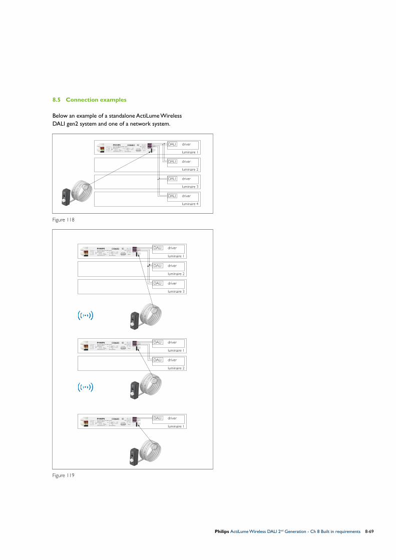
Philips ActiLume Wireless DALI 2nd Generation - Ch 8 Built in requirements 8-69
8.5 Connection examples
Below an example of a standalone ActiLume Wireless DALI gen2 system and one of a network system.
Figure 118
Figure 119
DALI driver
luminaire 2
DALI driver
luminaire 3
DALI driver
luminaire 4
driver
luminaire 1
DALI
Network
driver
luminaire 1
DALI
DALI driver
luminaire 3
DALI driver
luminaire 2
driver
luminaire 1
DALI
DALI driver
luminaire 2
driver
luminaire 1
DALI

Philips ActiLume Wireless DALI 2nd Generation - Ch 9 OccuSwitch wireless movement detectors9-70
Besides the movement detector, that is part of the ActiLume Wireless DALI gen2 system, the area where motion detection needs to be active can be easily extended by one of the OccuSwitch wireless detectors LRM1763, LRM1765, LRM1770 and LRM1775. Each of these detectors has been designed for a specific application. The LRM1763 for example is designed to be mounted against the ceiling, whilst the LRM1765, LRM1770 and LRM1775 are specifically designed for applications that require movement sensor mounting in a corridor, corner or wall.
LRM1763 OSW Multi-sensorThe LRM1763 is a battery (SAFT LS 14500, 3.6 V lithium-thionyl chloride (Li-SOCl2) AA-size) powered multi-sensor. Generally mounted against the ceiling it has a, more or less, rectangular presence detection pattern of 3.6 x 5.4m for minor and 5.4 x 7.2m for major movements when mounted at a height of 2.5m. For additional product information refer to the datasheet.
Figure 120
Although the LRM1763 has an integrated daylight sensor this feature is not supported within a network created with ActiLume Wireless DALI gen2 systems.
LRM1765 OSW Corridor sensorThe LRM1765 is a battery (SAFT LS 14500, 3.6 V lithium-thionyl chloride (Li-SOCl2) AA-size) powered corridor sensor. Generally mounted at a height of 2.3m and it has a presence detection pattern of 6.1 x 45.0m. For additional product information refer to the datasheet.
Figure 121
9 OccuSwitch wireless movement detectors
7.2 m
5.4 m
5.4 m3.6 m
h = 2.5 m
45m
2.3m
6.1m
NoteHow the sensors can be linked into a network is described in paragraph 5.11.1 and as previously mentioned movement detection of these sensors is always at network level so not at zone level.

Philips ActiLume Wireless DALI 2nd Generation - Ch 9 OccuSwitch wireless movement detectors 9-71
LRM1770 OSW Corner sensorThe LRM1770 is a battery (SAFT LS 14500, 3.6 V lithium-thionyl chloride (Li-SOCl2) AA-size) powered corner sensor. Generally mounted at a height of 2.3m and it has a rectangular presence detection pattern of 10.0 x 10.0m for minor and 15.0 x 15.0m for major movements. For additional product information refer to the datasheet.
Figure 122
LRM1775 OSW Wall sensorThe LRM1775 is a battery (SAFT LS 14500, 3.6 V lithium-thionyl chloride (Li-SOCl2) AA-size) powered wall sensor. Generally mounted at a height of 2.3m and it has a rectangular presence detection pattern of 10.0 x 10.0m for minor and 15.0 x 15.0m for major movements. For additional information on the product refer to the datasheet.
Figure 123
15m
2.3m
10m
15m10m
15m
2.3m
10m
15m10m

Philips ActiLume Wireless DALI 2nd Generation - Ch 10 MultiOne10-72
This chapter is an introduction on how to configure (commission) the ActiLume Wireless DALI gen2 system using the MultiOne software in combination with the LCN8650 USB2ZigBee dongle (hardware). The software contains two manuals, in .pdf format, to provide background and detailed user information. To open these manuals, one “Getting started” and one “User manual”, a suitable reader needs to be installed (recommendation Adobe Reader).To obtain the MultiOne software go to the www.philips.com/MultiOne website and select MultiOne Engineering 2.7 or higher, when prompted choose Open and use the computers unzip facility to unpack and save the file.
Before installing the software request a User Software Key by clicking on the link on the web-page and filling in the required information.
Double click on the saved .exe file and follow on screen instructions to install the MultiOne software.Once the MutiOne software is installed insert the USB2ZigBee dongle into a free USB 2.0 port. Its driver is then automatically installed.
10.1 Starting MultiOne software
If a shortcut, on the desktop of the computer, was created double click on it to start the software. If no shortcut was created search your computer and start the software from the applicable location. All screen shots shown are of MultiOne release 2.7.The Application mode start screen is shown.
Figure 124
From this screen you have access to the “Getting started” and “User manual” and have the option to remember your choice and not show this screen after restarting.
Select the Application mode “All” button.After opening (see window beneath) tabs regarding Device features, Commands, Traceability, Scheduler, Query and Diagnostics are visible but these are not relevant for ActiLume Wireless DALI gen2.
Figure 125
Select Tools -> Connection settings
Figure 126
10 MultiOne
NoteThe LCN8650 USB2ZigBee dongle has to be ordered separately.

Philips ActiLume Wireless DALI 2nd Generation - Ch 10 MultiOne 10-73
Select the ZigBee radio button, check to confirm the selected port number, and confirm by selecting the OK button.
Figure 127
If the COM port is not shown press the refresh button.
10.2 Gaining access to a ActiLume Wireless DALI gen2 network
To gain access to an existing network, created with ActiLume Wireless DALI gen2 systems, it must be in the “Opened network” state (refer to paragraph 5.11). Please note that only connection to one (1) network can be established.
Select the Connect to network button and wait for the devices to be identified. Depending on the amount of devices in the network, identifying can take anywhere between a few seconds to several minutes.
Figure 128
During the process of identification the USB2ZigBee dongle is linked into the network.
In the example below two ActiLume Wireless DALI gen2 devices have been identified to form the network.
Figure 129
Now bring the network bring it into the “Test and Configuration” state (refer to paragraph 5.7)
By right clicking on a device, in this case an ActiLume Wireless DALI gen2 controller and selecting Identify the connected lights of the ActilLume Wireless DALI gen2 will flash twice. This helps to visually identify the position of the device in the network. The same procedure can be used to identify the position of OccuSwitch Wireless sensors in the network but in this case the LED on the OSW will flash for approximately 100s.
The General tab shows information about the device that is highlighted in the Network pane (left hand side). When making changes in the General tab, for example changing the IR channel (IR group address) this change needs to be written to the device.For details on the capabilities and use of the MultiOne tool, in combination with the USB2Zigbee dongle, refer to the appropriate manuals.
Once configuration is completed lock the network (refer to paragraph 5.6) bringing it into the “Operational” state. Close the software and remove the USB2Zigbee dongle from the computer.

Philips ActiLume Wireless DALI 2nd Generation - Ch 11 FAQ11-74
Q1: What is the definition of an ActiLume Wireless DALI gen2 system?A1: It is a combination of one (1) ActiLume Wireless DALI gen2 (LLC1686) combined with one (1) ActiLume gen2 multi-sensor (LRI1663).
Q2: How many ActiLume Wireless DALI gen2 systems can form one (1) network?A2: A maximum of 50 ActiLume Wireless DALI gen2 systems.
Q3: Can Philips ZigBee wireless devices be included and/or used with a network?A3: Yes, a limited amount of sensors, switches and remotes can be used (refer to paragraph 2.5).
Q4: How many OccuSwitch Wireless sensors can be part of a network?A4: A maximum of 10 OSW sensors can be part of a network with the restriction that there may never be more OSW sensors than ActiLume Wireless DALI gen2 controllers.
Q5: How many Wireless Scene Control remotes can be part of a network?A5: A maximum of 5 ZigBee remotes can be part of a network
Q6: Is there a limitation on the amount of ZigBee Green Power devices that can be part of a network?A6: Yes, maximally 5, either switches or scene selector, can be part of a network.
Q7: Can a network be created with just ActiLume Wireless DALI gen2 controllers (LLC1686)?A7: No, during network creation the ActiLume gen2 multi-sensor has to be connected to the controller as the IR receiver part is needed to gain access to the network. There is no other way to create a network.
Q8: Can the ActiLume Wireless DALI gen2 be used without ActiLume muti-sensor?A8: In principle yes. In order to do so, the movement
detector and daylight sensor need to be disabled and after that, the occupancy mode of the ActiLume Wireless DALI gen2 controller needs to be set to Manual on/Manual off via the MultiOne tool in the active mode. When this is done, the sensor can be removed. Hence: the ActiLume needs to be in a network so it can act on other signals coming from other devices.
Q9: Do all luminaires in a network need to be equipped with the ActiLume Wireless DALI gen2 system?A9: No, as each ActiLume Wireless DALI gen2 controller can drive upto a maximum of 4 DALI drivers that in general will not be mounted in one luminaire (refer to configuration example in paragraph 8.5).
Q10: How many zones can be created in one (1) network?A10: The maximum amount is 32 zones.
Q11: Can OccuSwitch Wireless sensors be added to one or more zones?A11: No, wireless sensors are always part of the network not of a zone within a network.
Q12: Can zones be assigned to independent IR group addresses?A12: Yes, but please notice that as On/Off commands from remotes are relayed across the network all luminaires will respond even if assigned to different IR group addresses.
Q13: Is it practical to assign different IR group addresses to zones to achieve local control?A13: No, see previous Q and A. If local control is required create two or more small networks with different IR group addresses.
Q14: What is the average battery lifetime of OccuSwitch Wireless (LRM1763, LRM1765, LRM1770 and LRM1775) sensors?A14: The average lifetime is 10 years. Q15: What is the average battery lifetime of the Wireless Scene Control (UID8410) remote control?A15: The average lifetime is 2 years.
Q16: What is the average battery lifetime of the IR remotes?A16: The average lifetime is 4 - 5 years.
Q17: When does the battery of a ZGP device need to be replaced?A17: Not at all as these devices function without any electrical source. By pressing buttons the required energy is generated.
11 FAQ

Philips ActiLume Wireless DALI 2nd Generation - Ch 11 FAQ 11-75
Q18: Is there a maximum wiring length between the Touch and Dim button and ActiLume Wireless DALI gen2 controller? A18: In principle not but if the wiring gets too long it is possible that disturbances will be picked up generating undesired ActiLume Wireless DALI gen2 controller behavior. The following R/C filter can be mounted, at the ActiLume Wireless DALI gen2 controller side.
Figure 130
Q19: How many ballasts/drivers can I connect to one ActiLume Wireless DALI gen2 (LLC1686)?A19: A maximum of 4 drivers is permitted as the current output of the controller is limited at 8mA.
Q20: Is it allowed to connect an external DALI power supply to the DALI lines?A20: No, this will permanently damage connected ActiLume Wireless DALI gen2 devices.
Q21: I cannot link my UID8410 Wireless Scene Remote to a new network although it has previously been used in another network?A21: The UID8410 remembers the network it has
been linked into by storing network information into its memory. Before it can be linked into a new network the “old” network data must be cleared. To clear the memory remove the back cover and insert a paperclip in the hole marked with text reset. Keep the button depressed until an audible signal is generated. Mount back cover on the remote control.
Q22: Can I connect 2 or more ActiLume Wireless DALI gen2 in parallel to one (1) Touch and Dim button?A22: No, this is not possible since the ActiLume Wireless DALI gen2 has no synchronization implemented.
Q23: Can I connect 2 or more Touch and Dim buttons in parallel to one (1) ActiLume Wireless DALI gen2?A24: Yes, this is possible, but keep in mind the the possibility of additional disturbances (also see Q/A 18 on length of the Touch and Dim line).
Q25: Is daylight regulation still active when using the Touch and Dim button?A25: No, daylight regulation will be switched off?
Q26: Where can I find all ins and outs about the “MultiOne” software?A26: In this Application guide there is a chapter on the
use and capabilities of the MultiOne tool related to the ActiLume Wireless DALI gen2 system. Details on the tool can be found in “Getting started” and “User manual” that are an integrated part of the tool. You can find these documents on either the Application mode (start screen) or in the pull-down menu at the top navigation bar under de heading “Help”.
Q27: I cannot open the two documents on the use of the MultiOne tool?A27: The documents are in .pdf format and a tool that is capable of opening these files is required. A free and suitable tool is Acrobat Reader.
Q28: Is it possible to deactivate the daylight sensor and movement detector separately with IRT9090?A28: Yes, it is possible to (de)activate the daylight and movement sensor (PIR) independently from one another (refer to paragraphs 6.12 and 6.11 for details).
Q29: Is it possible to deactivate the daylight sensor and movement detector separately with the MultiOne tool?A29: Yes, it is possible to (de)activate the daylight and movement sensor (PIR) independently from one another by placing, or removing, tick marks in checkboxes.
Q30: Can I still use the LRA1750 Actuator block with ActiLume Wireless DALI gen2?A30: No, the LRA1750 cannot be used in combination with the LLC1686 ActiLume Wireless DALI gen2.
Touch and Dimswitch
100 OhmType MRS25
330 nFType X2-275V
PENL
Ls
PENL
Act
iLum
e W
irele
ss D
ALI
gen
2
Mai
ns

Philips ActiLume Wireless DALI 2nd Generation - Ch 11 FAQ11-76
Q31: Is daylight information distributed across the network?A31: No, because that would give too much data transmission and would therefore interfere with occupancy sharing across the network.
Q32: Can I connect ZigBee devices from other manufacturers to the ActiLume Wireless DALI gen2 system?A32: No, this is not possible as the system uses encrypted communication and this encryption is not shared with other manufacturers.
Q33: Can I connect multiple LRI1663 and/or LRI1667 to one (1) ActiLume Wireless DALI gen2?A33: No, this is not allowed. Only one (1) LRI1663 or LRI1667 may be connected to one (1) ActiLume Wireless DALI gen2.
Q34: Does the system have a default RF channel?A34: No, there is no default RF channel. When creating
a network the first ActiLume Wireless DALI gen2 system will automatically choose one of three available channels.
Q35: If transmission/reception gets worse over
time, will the system hop to a different RF channel?
A35: No, during operation, the channel will never change. The used channel can only be intentionally changed according to paragraph 6.6. Channel change is active for all ActiLume Wireless DALI gen2 systems in the network as well as for OccuSwitch Wireless devices and RF remotes UID8410 that are part of the network. All ZigBee Green Power devices however need to be manually relinked into the network.
Q36: How is it secured that all ActiLume Wireless
DALI gen2 systems in a network are on the same RF channel?
A36: When an additional ActiLume Wireless DALI gen2 system needs to be linked into a network (by pressing “add” on the IRT9090), it will check for an open network operating on one of three available RF channels. As soon as it finds an open network it will join automatically and keep attached to the RF channel the network is operating on.

Philips ActiLume Wireless DALI 2nd Generation - Ch 12 Abbreviations 12-77
Abbreviations used throughout this document are in alphabetical order:
DALI = Digital Addressable Lighting Interface
DDO = Daylight Dependent Override (if sufficient daylight then disable the Auto on function).
DDR = Daylight Dependent Regulation
DDS = Daylight Dependent Switching (if sufficient daylight available then lights switch off).
HVAC = Heating Ventilation Air Conditioning
IR = Infra-Red
OOTB = Out Of The Box
OSW = OccuSwitch Wireless
PIR = Passive Infra-Red
ZGP = ZigBee Green Power
12 Abbreviations

© 2015 Koninklijke Philips N.V.
All rights reserved. No part of this publication may be reproduced, transmitted, transcribed, stored in a
retrieval system or translated into any language or computer language, in any form or by any means, electronic,
mechanical, magnetic, optical, chemical, manual or otherwise, without prior written permission from Philips.
Brands and product names are trademarks or registered trademarks of their respective companies.
3222 636 49821, February 2015
Additional information can be found at:www.philips.com/controls