AceXtreme C Software Development Kit Software Reference Manual
989
AceXtreme ® C Software Development Kit Software Reference Manual © 2010 Data Device Corporation. All trademarks are the property of their respective owners. Model: BU-69092SX For more information: www.ddc-web.com/BU-69092SX The AceXtreme ® C Software Development Kit (SDK) provides the framework for efficient development of applications with DDC’s series of MIL-STD-1553 components and cards.
Transcript of AceXtreme C Software Development Kit Software Reference Manual

AceXtreme® C Software Development Kit
Software Reference Manual
© 2010 Data Device Corporation. All trademarks are the property of their respective owners.
Model: BU-69092SX
For more information: www.ddc-web.com/BU-69092SX
The AceXtreme® C Software Development Kit (SDK) provides the framework for efficient development of applications with DDC’s series of MIL-STD-1553 components and cards.

DDC's Data Networking SolutionsMIL-STD-1553 | ARINC 429 | Fibre Channel
As the leading global supplier of data bus components, cards, and software solutions for the military, commercial, and aerospace markets, DDC’s data bus networking solutions encompass the full range of data interface protocols from MIL-STD-1553 and ARINC 429 to USB, and Fibre Channel, for applications utilizing a spectrum of form-factors including PMC, PCI, Compact PCI, PC/104, ISA, and VME/VXI.
DDC has developed its line of high-speed Fibre Channel and Extended 1553 products to support the real-time processing of field-critical data networking netween sensors, compute notes, data storage displays, and weapons for air, sea, and ground military vehicles.
Whether employed in increased bandwidth, high-speed serial communications, or traditional avionics and ground support applications, DDC's data solutions fufill the expanse of military requirements including reliability, determinism, low CPU utilization, real-time performance, and ruggedness within harsh environments. Out use of in-house intellectual property ensures superior mutli-generational support, independent of the life cycles of commercial devices. Moreover, we maintain software compatibility between product generations to protect our customers' investments in software development, system testing, and end-product qualification.
DDC provides an assortment of quality MIL-STD-1553 commercial, military, and COTS grade cards and components to meet your data conversion and data interface needs. DDC supplies MIL-STD-1553 board level products in a variety of form factors including AMC, USB, PCI, cPCI, PCI-104, PCMCIA, PMC, PC/104, PC/104-Plus, VME/VXI, and ISAbus cards. Our 1553 data bus board solutions are integral elements of military, aerospace, and industrial applications. Our extensive line of military and space grade components provide MIL-STD-1553 interface solutions for microprocessors, PCI buses, and simple systems. Our 1553 data bus solutions are designed into a global network of aircraft, helicopter, and missle programs.
DDC also has a wide assortment of quality ARINC-429 commercial, military, and COTS grade cards and components, which will meet your data conversion and data interface needs. DDC supplies ARINC-429 board level products in a variety of form factors including AMC, USB, PCI, PMC, PCI-104, PC/104 Plus, and PCMCIA boards. DDC's ARINC 429 components ensure the accurate and reliable transfer of flight-critical data. Our 429 interfaces support data bus development, validation, and the transfer of flight-critical data aboard commercial aerospace platforms.
MIL-STD-1553
ARINC 429
DDC has developed its line of high-speed Fibre Channel network access controllers and switches to support the real-time processing demands of field-critical data networking between sensors, computer nodes, data storage, displays, and weapons, for air, sea, and ground military vehicles. Fibre Channel's architecture is optimized to meet the performance,reliability, and demanding environmental requirements of embedded, real time, military applications, and designed to endure the multi-decade life cycle demands of military/aerospace programs.
Fibre Channel

D A T A D E V I C E C O R P O R A T I O N
Data Device Corporation BU-69092SX Software Reference Manual www.ddc-web.com Rev G-3/16
i
BU-69092SX ACEXTREME® C SDK SOFTWARE REFERENCE MANUAL
MN-69092SX-003
The information provided in this Software Reference Manual is believed to be accurate;
however, no responsibility is assumed by Data Device Corporation for its use, and no license or rights are granted by implication or otherwise connection therewith.
Specifications are subject to change without notice.
Please visit our Web site at http://www.ddc-web.com/ for the latest information.
All rights reserved. No part of this Software Reference Manual may be reproduced or transmitted in any form or by any mean, electronic, mechanical photocopying
recording, or otherwise, without the prior written permission of Data Device Corporation.
105 Wilbur Place Bohemia, New York 11716-2426
Tel: (631) 567-5600, Fax: (631) 567-7358 World Wide Web - http://www.ddc-web.com
For Technical Support - 1-800-DDC-5757 ext. 7771 United Kingdom - Tel: +44-(0)1635-811140, Fax: +44-(0)1635-32264 France - Tel: +33-(0)1-41-16-3424, Fax: +33-(0)1-41-16-3425 Germany - Tel: +49-(0)89-15 00 12-11, Fax: +49-(0)89-15 00 12-22 Japan - Tel: +81-(0)3-3814-7688, Fax: +81-(0)3-3814-7689 Asia - Tel: +65 6489 4801 © 2010 Data Device Corp.
R E C O R D O F C H A N G E
Data Device Corporation BU-69092SX Software Reference Manual www.ddc-web.com Rev G-3/16
ii
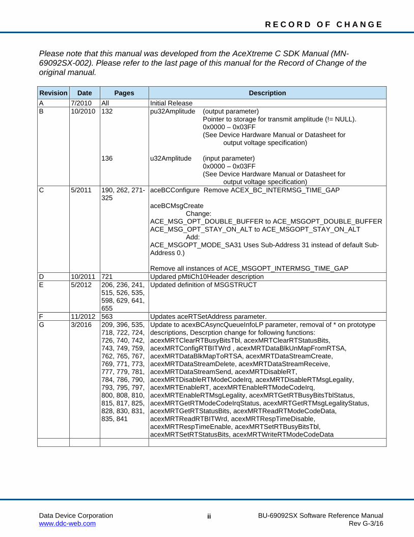
Please note that this manual was developed from the AceXtreme C SDK Manual (MN-69092SX-002). Please refer to the last page of this manual for the Record of Change of the original manual. Revision Date Pages Description A 7/2010 All Initial Release B 10/2010 132
136
pu32Amplitude (output parameter) Pointer to storage for transmit amplitude (!= NULL). 0x0000 – 0x03FF (See Device Hardware Manual or Datasheet for
output voltage specification) u32Amplitude (input parameter) 0x0000 – 0x03FF (See Device Hardware Manual or Datasheet for
output voltage specification) C 5/2011 190, 262, 271-
325 aceBCConfigure Remove ACEX_BC_INTERMSG_TIME_GAP aceBCMsgCreate Change: ACE_MSG_OPT_DOUBLE_BUFFER to ACE_MSGOPT_DOUBLE_BUFFER ACE_MSG_OPT_STAY_ON_ALT to ACE_MSGOPT_STAY_ON_ALT Add: ACE_MSGOPT_MODE_SA31 Uses Sub-Address 31 instead of default Sub-Address 0.) Remove all instances of ACE_MSGOPT_INTERMSG_TIME_GAP
D 10/2011 721 Updared pMtiCh10Header description E 5/2012 206, 236, 241,
515, 526, 535, 598, 629, 641, 655
Updated definition of MSGSTRUCT
F 11/2012 563 Updates aceRTSetAddress parameter. G 3/2016 209, 396, 535,
718, 722, 724, 726, 740, 742, 743, 749, 759, 762, 765, 767, 769, 771, 773, 777, 779, 781, 784, 786, 790, 793, 795, 797, 800, 808, 810, 815, 817, 825, 828, 830, 831, 835, 841
Update to acexBCAsyncQueueInfoLP parameter, removal of * on prototype descriptions, Descrption change for following functions: acexMRTClearRTBusyBitsTbl, acexMRTClearRTStatusBits, acexMRTConfigRTBITWrd , acexMRTDataBlkUnMapFromRTSA, acexMRTDataBlkMapToRTSA, acexMRTDataStreamCreate, acexMRTDataStreamDelete, acexMRTDataStreamReceive, acexMRTDataStreamSend, acexMRTDisableRT, acexMRTDisableRTModeCodeIrq, acexMRTDisableRTMsgLegality, acexMRTEnableRT, acexMRTEnableRTModeCodeIrq, acexMRTEnableRTMsgLegality, acexMRTGetRTBusyBitsTblStatus, acexMRTGetRTModeCodeIrqStatus, acexMRTGetRTMsgLegalityStatus, acexMRTGetRTStatusBits, acexMRTReadRTModeCodeData, acexMRTReadRTBITWrd, acexMRTRespTimeDisable, acexMRTRespTimeEnable, acexMRTSetRTBusyBitsTbl, acexMRTSetRTStatusBits, acexMRTWriteRTModeCodeData

T A B L E O F C O N T E N T S
Data Device Corporation BU-69092SX Software Reference Manual www.ddc-web.com Rev G-3/16
iii
1 SOFTWARE LICENSE AND POLICIES .............................................................. 1
2 PREFACE ............................................................................................................. 6 2.1 Text Usage .................................................................................................................. 6 2.2 Standard Definitions .................................................................................................... 6 2.3 Special Handling and Cautions ................................................................................... 7 2.4 Trademarks ................................................................................................................. 7 2.5 Technical Support ....................................................................................................... 7
3 OVERVIEW .......................................................................................................... 8 3.1 SDK Features.............................................................................................................. 8 3.2 Supported Operating Systems .................................................................................... 9 3.3 Related Documentation ............................................................................................... 9
4 API FUNCTION DEFINITIONS ........................................................................... 10 4.1 General Functions ..................................................................................................... 11 4.2 BC Functions........................................................................................................... 162 4.3 RT Functions ........................................................................................................... 470 4.4 RTMT Functions ...................................................................................................... 585 4.5 MT Functions .......................................................................................................... 618 4.6 MT-I Functions ........................................................................................................ 680 4.7 RTMT-I Functions ................................................................................................... 728 4.8 Multi RT Functions .................................................................................................. 738 4.9 Avionics I/O Functions ............................................................................................. 843 4.10 Discrete I/O Functions ............................................................................................. 858
5 OPERATING SYSTEM SPECIFIC FUNCTIONS ............................................. 873 5.1 VxWorks Functions ................................................................................................. 873 5.2 DOS Functions ........................................................................................................ 890
6 STRUCTURES ................................................................................................. 894
7 APPENDIX A .................................................................................................... 951 7.1 Error and Warning Messages .................................................................................. 951
8 APPENDIX B .................................................................................................... 974
9 INDEX ............................................................................................................... 977

L I S T O F T A B L E S
Data Device Corporation BU-69092SX Software Reference Manual www.ddc-web.com Rev G-3/16
iv
Table 1. DDC Type Definitions .................................................................................................... 6 Table 2. Functional Grouping .................................................................................................... 10 Table 3. General Functions Listing ............................................................................................ 11 Table 4. BC Functions Listing .................................................................................................. 162 Table 5. RT Functions Listing .................................................................................................. 470 Table 6. RTMT Functions Listing ............................................................................................. 585 Table 7. MT Functions Listing.................................................................................................. 618 Table 8. MT-I Functions Listing ............................................................................................... 680 Table 9. RTMT-I Functions Listing ........................................................................................... 728 Table 10. Multi RT Functions Listing ....................................................................................... 738 Table 11. Avionics I/O Functions Listing .................................................................................. 843 Table 12. Discrete I/O Functions Listing .................................................................................. 858 Table 13. Operating System Specific Grouping ....................................................................... 873 Table 14. VxWorks Functions Listing ...................................................................................... 873 Table 15. DOS Functions Listing ............................................................................................. 890 Table 16. Structures Listing ..................................................................................................... 894 Table 17. ACEX_DISC_CONFIG ............................................................................................ 899 Table 18. ACEX_TRG_CONFIG_GPT .................................................................................... 904 Table 19. ACEX_TRG_CONFIG_TMT .................................................................................... 906

Data Device Corporation BU-69092SX Software Reference Manual www.ddc-web.com Rev G-3/16
1
1 SOFTWARE LICENSE AND POLICIES IMPORTANT—READ CAREFULLY: This Software License Agreement (“SLA”) is a legal agreement between you (either an individual or a single entity) and Data Device Corporation (DDC) for this DDC software product, which includes computer software and may include associated media, printed materials, and “online” or electronic documentation (“Product”). YOU AGREE TO BE BOUND BY THE TERMS OF THIS SLA BY INSTALLING, COPYING, OR OTHERWISE USING THE PRODUCT. IF YOU DO NOT AGREE, DO NOT INSTALL OR USE THE PRODUCT; YOU MAY RETURN IT TO YOUR PLACE OF PURCHASE FOR A FULL REFUND.
GRANT OF LICENSE
DDC grants you the following rights provided that you comply with all terms and conditions of this SLA:
Installation and use. You may install, use, access, display and run one copy of the Product on a single computer, such as a workstation, terminal or other device (“Workstation Computer”). The Product may not be used in conjunction with non-DDC devices. You may not use the Product to permit any Device to use, access, display or run other executable software residing on the Workstation Computer, nor may you permit any Device to use, access, display, or run the Product or Product’s user interface, unless the Device has a separate license for the Product.
Storage/Network Use. You may also store or install a copy of the Product on a storage device, such as a network server, used only to install or run the Product on your other Workstation Computers over an internal network; however, you must acquire and dedicate an additional license for each separate Workstation Computer on or from which the Product is installed, used, accessed, displayed or run. A license for the Product may not be shared or used concurrently on different Workstation Computers.
Reservation of Rights. DDC reserves all rights not expressly granted to you in this SLA.
UPGRADES
To use a Product identified as an upgrade, you must first be licensed for the product identified by DDC as eligible for the upgrade. After upgrading, you may no longer use the product that formed the basis for your upgrade eligibility.

S O F T W A R E L I C E N S E A N D P O L I C I E S
Data Device Corporation BU-69092SX Software Reference Manual www.ddc-web.com Rev G-3/16
2
ADDITIONAL SOFTWARE/SERVICES
This SLA applies to updates of the Product that DDC may provide to you or make available to you after the date you obtain your initial copy of the Product, unless we provide other terms along with the update.
TRANSFER
You may move the Product to a different Workstation Computer. After the transfer, you must completely remove the Product from the former Workstation Computer. You may not rent, lease, lend or provide commercial services to third parties with the Product.
LIMITATION ON REVERSE ENGINEERING, DECOMPILATION, AND DISASSEMBLY
You may not reverse engineer, decompile, or disassemble the Product.
TERMINATION
Without prejudice to any other rights, DDC may cancel this SLA if you do not abide by the terms and conditions of this SLA, in which case you must return all copies of the Product and all of its component parts.
EXPORT RESTRICTIONS
You acknowledge that the Product is of U.S. origin and subject to U.S. export jurisdiction. You agree to comply with all applicable international and national laws that apply to the Product, including the U.S. Export Administration Regulations, as well as end-user, end-use, and destination restrictions issued by U.S. and other governments.
LIMITED WARRANTY FOR PRODUCT
DDC warrants that the Product will perform substantially in accordance with the accompanying materials for a period of one (1) year from the date of receipt. Except for the warranty made above, DDC makes no warranty or representation of any kind, express or implied, with respect to the Products, including warranty as to their merchantability or fitness for a particular purpose or as to any other matter. All claims based upon defects shall be deemed waived unless made in writing and received by DDC within one (1) year after your receipt of the Product. New Product updates are available without charge during this one (1) year term of this warranty.

S O F T W A R E L I C E N S E A N D P O L I C I E S
Data Device Corporation BU-69092SX Software Reference Manual www.ddc-web.com Rev G-3/16
3
ANNUAL MAINTENANCE CONTRACT
After the expiration of the one (1) year limited warranty period, a Maintenance Contract may be purchased from DDC to extend the Product warranty period for an additional one (1) year from date of expiration. With the purchase of a valid Annual Maintenance Contract, the clauses defined in Section 8 shall remain intact. Maintenance Contracts can be renewed annually and must remain valid, without any lapses, to extend the Product warranty period.
LIMITATION ON REMEDIES; NO CONSEQUENTIAL OR OTHER DAMAGES
Your exclusive remedy for any breach of this Limited Warranty is as set forth below. Except for any refund elected by DDC, YOU ARE NOT ENTITLED TO ANY DAMAGES, INCLUDING BUT NOT LIMITED TO CONSEQUENTIAL DAMAGES, if the Product does not meet DDC’s Limited Warranty, and, to the maximum extent allowed by applicable law, even if any remedy fails of its essential purpose. The terms of Section 0 below (“Exclusion of Incidental, Consequential and Certain Other Damages”) are also incorporated into this Limited Warranty. You may have others, which vary from state/jurisdiction to state/jurisdiction.
YOUR EXCLUSIVE REMEDY
DDC’s and its suppliers’ entire liability and your exclusive remedy shall be, at DDC’s option from time to time exercised subject to applicable law, (a) return of the price paid (if any) for the Product, or (b) repair or replacement of the Product, that does not meet this Limited Warranty and that is returned to DDC. You will receive the remedy elected by DDC without charge, except that you are responsible for any expenses you may incur (e.g. cost of shipping the Product to DDC). This Limited Warranty is void if failure of the Product has resulted from accident, abuse, misapplication, abnormal use or a virus. Any replacement Product will be warranted for the remainder of the original warranty period or thirty (30) days, whichever is longer.
DISCLAIMER OF WARRANTIES
The Limited Warranty that appears above is the only express warranty made to you and is provided in lieu of any other express warranties (if any) created by any documentation, packaging, or other communications. Except for the Limited Warranty and to the maximum extent permitted by applicable law, DDC and its suppliers provide the Product and support services (if any) AS IS AND WITH ALL FAULTS, and hereby disclaim all other warranties and conditions, either express, implied or statutory, including, but not limited to, any (if any) implied warranties, duties or conditions of merchantability, of fitness for a particular purpose, of reliability or availability, of accuracy or completeness of responses, of results, of workmanlike effort, of lack of viruses, and of lack of negligence, all with regard to the Product, and the provision of

S O F T W A R E L I C E N S E A N D P O L I C I E S
Data Device Corporation BU-69092SX Software Reference Manual www.ddc-web.com Rev G-3/16
4
or failure to provide support or other services, information, software, and related content through the Product or otherwise arising out of the use of the Product.
EXCLUSION OF INCIDENTAL, CONSEQUENTIAL AND CERTAIN OTHER DAMAGES
TO THE MAXIMUM EXTENT PERMITTED BY APPLICABLE LAW, IN NO EVENT SHALL DDC OR ITS SUPPLIERS BE LIABLE FOR ANY SPECIAL, INCIDENTAL, PUNITIVE, INDIRECT, OR CONSEQUENTIAL DAMAGES WHATSOEVER (INCLUDING, BUT NOT LIMITED TO, DAMAGES FOR LOSS OF PROFITS OR CONFIDENTIAL OR OTHER INFORMATION, FOR BUSINESS INTERRUPTION, FOR PERSONAL INJURY, FOR LOSS OF PRIVACY, FOR FAILURE TO MEET ANY DUTY INCLUDING OF GOOD FAITH OR OF REASONABLE CARE, FOR NEGLIGENCE, AND FOR ANY OTHER LOSS WHATSOEVER) ARISING OUT OF OR IN ANY WAY RELATED TO THE USE OF OR INABILITY TO USE THE PRODUCT, THE PROVISION OF OR FAILURE TO PROVIDE SUPPORT OR OTHER SERVICES, INFORMATON, SOFTWARE, AND RELATED CONTENT THROUGH THE PRODUCT OR OTHERWISE ARISING OUT OF THE USE OF THE PRODUCT, OR OTHERWISE UNDER OR IN CONNECTION WITH ANY PROVISION OF THIS SLA, EVEN IN THE EVENT OF THE FAULT, TORT (INCLUDING NEGLIGENCE), STRICT LIABILITY, BREACH OF CONTRACT OR BREACH OF WARRANTY OF DDC OR ANY SUPPLIER, AND EVEN IF DDC OR ANY SUPPLIER HAS BEEN ADVISED OF THE POSSIBILITY OF SUCH DAMAGES.
LIMITATION OF LIABILITY AND REMEDIES
Notwithstanding any damages that you might incur for any reason whatsoever (including, without limitation, all damages referenced above and all direct or general damages), the entire liability of DDC and any of its suppliers under any provision of this SLA and your exclusive remedy for all of the foregoing (except for any remedy of repair or replacement elected by DDC with respect to any breach of the Limited Warranty) shall be limited to the amount actually paid by you for the Product. The foregoing limitations, exclusions and disclaimers (including Sections 0, 0, 0, and 0above) shall apply to the maximum extent permitted by applicable law.
U.S. GOVERNMENT LICENSE RIGHTS
All Product provided to the U.S. Government is provided with the commercial license rights and restrictions described elsewhere herein.
APPLICABLE LAW
This SLA is governed by the laws of the State of New York.
S O F T W A R E L I C E N S E A N D P O L I C I E S
Data Device Corporation BU-69092SX Software Reference Manual www.ddc-web.com Rev G-3/16
5
ENTIRE AGREEMENT
This SLA (including any addendum or amendment to this SLA which is included with the Product) are the entire agreement between you and DDC relating to the Product and the support services (if any) and they supersede all prior or contemporaneous oral or written communications, proposals and representations with respect to the Product or any other subject matter covered by this SLA. To the extent the terms of any DDC policies or programs for support services conflict with the terms of this SLA, the terms of this SLA shall control.
The Product is protected by copyright and other intellectual property laws and treaties. DDC or its suppliers own the title, copyright, and other intellectual property rights in the Product. The Product is licensed, not sold.

Data Device Corporation BU-69092SX Software Reference Manual www.ddc-web.com Rev G-3/16
6
2 PREFACE This manual uses typographical conventions to assist the reader in understanding the content. This section will define the text formatting used in the rest of the manual.
2.1 Text Usage • BOLD – text that is written in bold letters indicates important information
and table, figure, and chapter references.
• BOLD ITALIC – will designate DDC Part Numbers.
• Courier New – is used to indicate code examples.
• <…> - Indicates user entered text or commands.
2.2 Standard Definitions E2MA Extended Enhanced Mini-ACE®
EMACE Enhanced Mini-ACE®
WORD 16-Bit Data (legacy term) DWORD 32-Bit Data (legacy term) BC MIL-STD-1553 Bus Controller MT MIL-STD-1553 Monitor Terminal
MT-I MIL-STD-1553 Monitor Terminal - Improvement
RT MIL-STD-1553 Remote Terminal Multi-RT MIL-STD-1553 Multiple Remote Terminals
HOST Controller connected to the Host Interface
PCI Peripheral Component Interconnect
MC Mode Code
GPQ General Purpose Queue
GPF General Purpose Flag
BIT Built-In Test
Table 1. DDC Type Definitions Name Intended Type*
U8BIT Unsigned 8-bit entity
U16BIT Unsigned 16-bit entity
U32BIT Unsigned 32-bit entity

P R E F A C E
Data Device Corporation BU-69092SX Software Reference Manual www.ddc-web.com Rev G-3/16
7
Table 1. DDC Type Definitions Name Intended Type*
U64BIT Unsigned 64-bit entity
S8BIT Signed 8-bit entity
S16BIT Signed 16-bit entity
S32BIT Signed 32-bit entity
S64BIT Signed 64-bit entity
BOOLEAN Unsigned char with intended-use values of TRUE (1) and FALSE (0)
*Note: The actual implementation of the DDC type in C is operating system
dependent.
2.3 Special Handling and Cautions
The BU-69092 is delivered on a Compact Disc. Proper care should be used to ensure that the discs are not damaged by heat.
2.4 Trademarks
All trademarks are the property of their respective owners.
2.5 Technical Support
In the event that problems arise beyond the scope of this manual, you can contact In the event that problems arise beyond the scope of this manual, you can contact DDC by the following:
US Toll Free Technical Support: 1-800-DDC-5757, ext. 7771
Outside of the US Technical Support: 1-631-567-5600, ext. 7771
Fax: 1-631-567-5758 to the attention of DATA BUS Applications
DDC Website: www.ddc-web.com/ContactUs/TechSupport.aspx
Please note that the latest revisions of Software and Documentation are available for download at DDC’s Web Site, www.ddc-web.com.

Data Device Corporation BU-69092SX Software Reference Manual www.ddc-web.com Rev G-3/16
8
3 OVERVIEW The AceXtreme® C Software Development Kit (SDK) provides the framework for developing real-time drivers and/or applications for the series of MIL-STD-1553 components and cards, while requiring minimal development time. The SDK provides a level of abstraction such that it is not necessary to understand the operation of the underlying DDC MIL-STD-1553 board or component.
All access to DDC hardware is performed through a high-level application programming interface (API) that encapsulate common procedures that the user would need to perform to setup and use a MIL-STD-1553 interface. Examples of such high-level procedures are BC setup, defining messages, defining frames, RT setup, and so on.
These API routines in turn access the DDC hardware through a common set of low level setup routines, read/write routines, and interrupt handlers. This allows the SDK to be easily ported to any hardware and/or software platform by modifying these routines.
This reference manual details each function provided in the AceXtreme C SDK API, as well as the supporting DDC C types and C structures used by them.
As a companion manual, the AceXtreme® C SDK Software Manual (MN-69092SX-002) is also available from DDC. This manual explains how to install and use the DDC API to implement MIL-STD-1553 applications.
3.1 SDK Features • Library of "C" Routines Available for:
Windows® 2000/XP/Vista/7, Linux®, and VxWorks® Operating Systems.
• Documentation Provided.
• Provides Modular, Portable, & Readable Code to Reduce Software Development Time.
• "C" Structures Eliminate Need to Learn Detailed Address/Bit Maps and Data Formats.
• Includes Sample Programs and Compiled Libraries for Quick Startup.
• Includes Multiple Environment/Compiler Support.

O V E R V I E W
Data Device Corporation BU-69092SX Software Reference Manual www.ddc-web.com Rev G-3/16
9
3.2 Supported Operating Systems • Windows 2000/XP, Windows Vista 32/64 bit, Windows 7 32/64 bit Operating
System with a development environment.
• Linux Operating System with kernel development tools and an appropriate compiler.
• VxWorks Real-Time Operating System and the Workbench intergrated development environment.
3.3 Related Documentation • AceXtreme C SDK Software Manual (MN-69092SX-002).
• For each OS and SDK version release, please see the provided Release Notes for information on supported hardware and OS variant.

Data Device Corporation BU-69092SX Software Reference Manual www.ddc-web.com Rev G-3/16
10
4 API FUNCTION DEFINITIONS This chapter contains every API function available in the AceXtreme C SDK. These high-level functions are defined as common instruction calls that will be used for board operations.
A detailed description of each API function contains information about the routine’s functionality, prototype, formal parameter list, possible errors encountered, return codes, and example code is contained in this section.
The #include file described in each of the function sections is the file that contains the function prototype. It should be noted that when creating a program, only the STDEMACE.H file should be included. All other included files will be accessed through the inclusion of this file.
The macros specified are defined in the appropriate header files. In many cases the defined macro will take on different values based on the operating system or compiler. One of the macros that is dependent upon the operating system and the compiler used is the _DECL element of the prototypes. This is not something that the user will generally change, but it should be noted that this is not a fixed value for all systems.
It is wise practice to check return values for errors. If an error exists, then an appropriate action should be taken. The error condition should never be ignored, as all operations to follow may not have a properly initialized state.
Table 2. Functional Grouping Functional Group Page
General Functions 11 BC Functions 162
RT Functions 470 RTMT Functions 585
MT Functions 618 MT-I Functions 680
RTMT-I Functions 728
Multi-RT Functions 738 Avionics I/O Functions 843 Discrete I/O Functions 858

G E N E R A L F U N C T I O N D E F I N I T I O N S
Data Device Corporation BU-69092SX Software Reference Manual www.ddc-web.com Rev G-3/16
11
4.1 General Functions
Table 3. General Functions Listing
Function Page aceCmdWordCreate 14
aceCmdWordParse 16
aceErrorStr 18
aceFree 20
aceGetBSWErrString 22
aceGetChannelCount 25
aceGetCoreVersion 27
aceGetHWVersionInfo 28
aceGetIRIGTx 30
aceGetLibVersion 32
aceGetMemRegInfo 34
aceGetMsgTypeString 36
aceGetSWVersionInfo 38
aceGetTimeTagValue 39
aceGetTimeTagValueEx 41
aceInitialize 43
aceInt80Enable 47
aceIOFree 49
aceIOInitalize 51
aceISQClear 53
aceISQEnable 55
aceISQRead 57
aceMemRead 59
aceMemRead32 61
aceMemWrite 63
aceMemWrite32 65
aceRegRead 67
aceRegRead32 69
aceRegWrite 71
aceRegWrite32 73
aceResetTimeTag 75
aceSetAddressMode 76
aceSetAsynclsr 78

G E N E R A L F U N C T I O N D E F I N I T I O N S
Data Device Corporation BU-69092SX Software Reference Manual www.ddc-web.com Rev G-3/16
12
Table 3. General Functions Listing
Function Page aceSetCanIsr 80
aceSetClockFreq 82
aceSetDecoderConfig 84
aceSetHubAddress 87
aceSetIRIGTx 89
aceSetIrqConditions 91
aceSetIrqConfig 99
aceSetMetrics 101
aceSetRamParityChecking 103
aceSetRespTimeOut 105
aceSetTimeTagRes 107
aceSetTimeTagValue 109
aceSetTimeTagValueEx 111
aceTestCanEbrLoop 113
aceTestIrqs 115
aceTestLoopBack 117
aceTestMemory 119
aceTestProtocol 121
aceTestRegisters 123
aceTestVectors 125
aceTestVectorsStatic 127
acexClrDiscConfigure 129
acexEITxShutdownDisable 130
acexEITxShutdownEnable 131
acexGetAmplitude 132
acexGetCoupling 134
acexSetAmplitude 136
acexSetCoupling 138
acexSetDiscConfigure 140
acexTRGConfigure 142
acexTRGDisable 144
acexTRGEnable 146
acexTRGEventDisable 148
acexTRGEventEnable 150
acexTRGEventSelect 152

G E N E R A L F U N C T I O N D E F I N I T I O N S
Data Device Corporation BU-69092SX Software Reference Manual www.ddc-web.com Rev G-3/16
13
Table 3. General Functions Listing
Function Page acexTRGGetStatus 155
acexTRGGetTimeTag Event 158
acexTRGReset 160

G E N E R A L F U N C T I O N D E F I N I T I O N S
Data Device Corporation BU-69092SX Software Reference Manual www.ddc-web.com Rev G-3/16
14
aceCmdWordCreate This function will create a command word from the input parts.
PROTOTYPE #include “MsgOp.h” S16BIT _DECL aceCmdWordCreate(U16BIT *pCmdWrd, U16BIT wRT, U16BIT wTR, U16BIT wSA, U16BIT wWC);
HARDWARE EMACE, E²MA, AceXtreme
STATE Not Applicable
MODE Not Applicable
PARAMETERS pCmdWrd (output parameter) Pointer to an U16BIT word that will contain the value of the command word wRT (input parameter) Remote Terminal Address Valid values: 0 - 31 wTR (input parameter) Transmit/Receive bit Valid values: 0 – 1 wSA (input parameter) Subaddress Valid values: 0 – 31 wWC (input parameter) Data Word Count/Mode Code Valid values: 0 – 31

G E N E R A L F U N C T I O N D E F I N I T I O N S
Data Device Corporation BU-69092SX Software Reference Manual www.ddc-web.com Rev G-3/16
15
aceCmdWordCreate (continued) DESCRIPTION
This function creates a command word when given its individual parts.
RETURN VALUE ACE_ERR_SUCCESS The function completed successfully ACE_ERR_INVALID_BUF The pCmdWrd pointer is Null ACE_ERR_PARAMETER An input parameter is invalid
EXAMPLE U16BIT wRT, wTR, wSA, wWC; U16BIT *pCmdWrd; pRT = 5; pTR = ACE_TX_CMD; pSA = 10; pWC = 4; nResult = aceCmdWordCreate(pCmdWrd, wRT, wTR, wSA, wWC); if(nResult < 0) { printf(“Error in aceCmdWordCreate() function \n”); PrintOutError(nResult); return; }
SEE ALSO aceCmdWordParse()

G E N E R A L F U N C T I O N D E F I N I T I O N S
Data Device Corporation BU-69092SX Software Reference Manual www.ddc-web.com Rev G-3/16
16
aceCmdWordParse This function parses the given command word into its individual parts.
PROTOTYPE #include “MsgOp.h” S16BIT _DECL aceCmdWordParse(U16BIT wCmdWrd, U16BIT *pRT, U16BIT *pTR, U16BIT *pSA, U16BIT *pWC);
HARDWARE EMACE, E²MA, AceXtreme
STATE Not Applicable
MODE Not Applicable
PARAMETERS wCmdWrd (input parameter) An U16BIT command word pRT (output parameter) Pointer to a value that will contain the Remote Terminal Address part of the command word pTR (output parameter) Pointer to a value that will contain the Transmit/Receive bit part of the command word pSA (output parameter) Pointer to a value that will contain the Subaddress part of the command word pWC (output parameter) Pointer to a value that will contain the Word Count part of the command word
DESCRIPTION This function parses the given command and outputs the individual parts of the command word into the output parameter pointers specified by the user.

G E N E R A L F U N C T I O N D E F I N I T I O N S
Data Device Corporation BU-69092SX Software Reference Manual www.ddc-web.com Rev G-3/16
17
aceCmdWordParse (continued) RETURN VALUE
ACE_ERR_SUCCESS The function completed successfully ACE_ERR_INVALID_BUF The pRT, pTR, pSA, and/or pWC output parameter specified by the
user is/are Null
EXAMPLE U16BIT wCmdWrd, pRT, pTR, pSA, pWC; WCmdWrd = 0x0821; S16BIT nResult = 0; nResult = aceCmdWordParse(wCmdWrd, &pRT, &pTR, &pSA, &pWC); if(nResult < 0) { printf(“Error in aceCmdWordParse() function \n”); PrintOutError(nResult); return; } else { printf(“RT Address = %d, T/R bit = %d”, pRT, pTR,); printf(“SubAddress = %d, WordCount = %d\n”, pSA, pWC); }
SEE ALSO aceCmdWordCreate()

G E N E R A L F U N C T I O N D E F I N I T I O N S
Data Device Corporation BU-69092SX Software Reference Manual www.ddc-web.com Rev G-3/16
18
aceErrorStr This function will pass general error information back to the user.
PROTOTYPE #include “errordef.h” S16BIT _DECL aceErrorStr(S16BIT nError, char *pBuffer, U16BIT wBufSize);
HARDWARE EMACE, E²MA, AceXtreme
STATE Not Applicable
MODE Not Applicable
PARAMETERS nError (input parameter) The error number to return general information about pBuffer (output parameter) A pointer to a character buffer for the returned text string wBufSize (input parameter) Size of character buffer Valid values: >=80
DESCRIPTION This function is used to pass an error information string back to the user. The string is passed using a character buffer. The user must pass in the error number and the size of the buffer.
RETURN VALUE ACE_ERR_SUCCESS The function completed successfully ACE_ERR_INVALID_BUF An invalid pointer to the character buffer was input by the user or
the specified character buffer size is too small

G E N E R A L F U N C T I O N D E F I N I T I O N S
Data Device Corporation BU-69092SX Software Reference Manual www.ddc-web.com Rev G-3/16
19
aceErrorStr (continued) EXAMPLE
S16BIT DevNum = 0; char Buffer[80]; U16BIT wMemAddr = 0x03; U16BIT wValue = 0xFFFF; S16BIT nResult = 0; nResult = aceMemWrite(DevNum, wMemAddr, wValue); if(nResult < 0) { aceErrorStr(nResult, Buffer, 80); printf("SDK Function Failure-> %s.\n",pBuffer); }
SEE ALSO None

G E N E R A L F U N C T I O N D E F I N I T I O N S
Data Device Corporation BU-69092SX Software Reference Manual www.ddc-web.com Rev G-3/16
20
aceFree Frees all resources used by the hardware based on the type of access used.
PROTOTYPE #include “config.h” S16BIT _DECL aceFree(S16BIT DevNum);
HARDWARE EMACE, E²MA, AceXtreme
STATE Run, Ready
MODE Not Applicable
PARAMETERS DevNum (input parameter) Logical Device Number Valid values: 0 – 31
DESCRIPTION This routine must be issued when device operation is complete. It will free all resources used by the device so that they are available for other programs or devices to use. After this function has successfully completed, the device will be in a Reset state.
RETURN VALUE ACE_ERR_SUCCESS The function completed successfully ACE_ERR_INVALID_DEVNUM An invalid device number was input to this function ACE_ERR_INVALID_OS This operating system is not one of the following supported
types: Windows 2000/XP/Vista/7, Linux, or VxWorks
EXAMPLE S16BIT DevNum = 0; S16BIT nResult = 0; nResult = aceFree(DevNum); if(nResult < 0) { //an error has occurred so notify the user printf(“Error in aceFree() function \n”); PrintOutError(nResult); return; }

G E N E R A L F U N C T I O N D E F I N I T I O N S
Data Device Corporation BU-69092SX Software Reference Manual www.ddc-web.com Rev G-3/16
21
aceFree (continued)
SEE ALSO aceInitialize()

G E N E R A L F U N C T I O N D E F I N I T I O N S
Data Device Corporation BU-69092SX Software Reference Manual www.ddc-web.com Rev G-3/16
22
aceGetBSWErrString This function will return the block status word error string.
PROTOTYPE #include “MsgOp.h” char* _DECL aceGetBSWErrString(U16BIT wMode, U16BIT wBlkSts);
HARDWARE EMACE, E²MA, AceXtreme
STATE Not Applicable
MODE Not Applicable
PARAMETERS wMode (input parameter) Current Operating mode: Valid values: ACE_MODE_BC ACE_MODE_RT ACE_MODE_MT wBlkSts (input parameter) The block status word (BSW) of the message
DESCRIPTION This function returns a pointer to a character containing the given block status word error string.
RETURN VALUE Char * if (wMode = ACE_MODE_BC || ACE_MODE_RT || ACE_MODE_MT):
“INVWD” This indicates that an RT responded with one or more words containing one or more of the following error types: sync field error, Manchester encoding error, parity error, and/or bit count error
“INSYN” An RT responded with a Data sync in a Status Word and/or a Command/Status sync in a Data Word

G E N E R A L F U N C T I O N D E F I N I T I O N S
Data Device Corporation BU-69092SX Software Reference Manual www.ddc-web.com Rev G-3/16
23
aceGetBSWErrString (continued)
“WDCNT” The responding RT did not transmit the correct number of data words
“NOGAP”
The RT address field of a responding RT does not match the RT address in the Command Word and/or bit 8 of Configuration Register #5 at memory location 0x09 is set to logic 1 and a responding RT responds with a response time of less than 4 µs as per the MIL-STD-1553B standard.
“LPTST”
A loopback test is performed on the transmitted portion of every message in BC mode. A validity check is performed on the received version of every word transmitted by the BC. In addition, a bit-by-bit comparison is performed on the last word transmitted by the BC for each message. If either the received version of any transmitted word is invalid (sync, encoding, bit count, and/or parity error) and/or the received version of the last word transmitted by the BC does not match the transmitted version of this word, this error will occur.
“NORES”
This indicates that an RT has either not responded or has responded later than the BC No Response Timeout time. DDC’s “No Response Timeout Time” is defined as per the MIL-STD-1553B standard as the time from the mid-bit crossing of the parity bit to the mid-sync crossing of the RT Status Word. In the ENHANCED MODE DISABLE, the value of the BC Response Timeout is 17.5 to 19.5 µs. If ENHANCED MODE ENABLED is logic 1, the value of the No Response Timeout value is programmable from among the nominal values 18.5, 22.5, 50.5, and 130 µs (±1 µs) by means of bits 10 and 9 of Configuration Register #5 at memory location 0x09. The SDK sets ENHANCED MODE ENABLE to a value of 1 by default.
“FORMT”
This indicates that the received portion of a message contained one or more violations of the 1553 message validation criteria (sync, encoding, parity, bit count, word count, etc.), or the RT's status word received from a responding RT contained an incorrect RT address field.

G E N E R A L F U N C T I O N D E F I N I T I O N S
Data Device Corporation BU-69092SX Software Reference Manual www.ddc-web.com Rev G-3/16
24
aceGetBSWErrString (continued) If (wMode == ACE_MODE_RT):
“ILCMD” This indicates that the message has been illegalized. A message is
illegalized if ENHANCE MODE ENABLE (bit 15 of Configuration Register #3 is logic "0") or ILLEGALIZATION DISABLE (bit 7 of Configuration Register #3 is logic "0") and the appropriate bit for the respective Bcst/Tx/Rx-Subaddress-Word Count/Mode Code combination is set in the illegalization table (address locations 0300-03FF in the shared RAM). The SDK will legalize a message when the user calls the aceRTMsgLegalityEnable() function or the aceRTDataBlkMapToSA() function.
If (wMode==ACE_MODE_RT || ACE_MODE_MT):
“RTRTG” Indicates the BC (or transmitting RT in an RT to RT transfer)
transmitted one or more words containing one or more of the following error types: sync field error, Manchester encoding error, parity error, and/or bit count error.
“RTRTC” If the 1553 channel is the receiving RT for an RT to RT transfer,
this indicates one or more of the following error conditions in the transmit Command Word: (1) T/R* bit = logic "0"; (2)subaddress = 00000 or 11111; and/or (3) same RT address field as the receive.
“CMDER” Indicates a received command word is not defined in accordance
with the MIL-STD-1553B spec.
EXAMPLE /*get a decoded message from the hardware and display the error code in the BSW */ aceBCGetMsgFromIDDecoded(DevNum,MSG1,&pMsg,TRUE); // Display Error information if(pMsg->wBlkSts & 0x170f) { printf("\n ERROR: %s", aceGetBSWErrString(ACE_MODE_BC,pMsg->wBlkSts)); }
SEE ALSO None

G E N E R A L F U N C T I O N D E F I N I T I O N S
Data Device Corporation BU-69092SX Software Reference Manual www.ddc-web.com Rev G-3/16
25
aceGetChannelCount This function returns the number of discrete and avionic I/Os on a card.
PROTOTYPE #include “Dio.h” S16BIT _DECL aceGetChannelCount (S16BIT DevNum, CHANCOUNT *pChanCount);
HARDWARE E²MA, AceXtreme
STATE Ready, Run
MODE Not Applicable
PARAMETERS DevNum (input parameter) Logical Device Number Valid values: 0 - 31 pChanCount (output parameter) Pointer to storage for a CHANCOUNT structure
DESCRIPTION This function returns the number of discrete and avionic I/Os on E²MA or AceXtreme devices.
RETURN VALUE ACE_ERR_SUCCESS The function completed successfully ACE_ERR_INVALID_DEVNUM An invalid device number was used ACE_ERR_INVALID_STATE The device is not a Ready or Run State ACE_ERR_INVALID_CARD The device does not support this function ACE_ERR_PARAMETER Invalid parameter

G E N E R A L F U N C T I O N D E F I N I T I O N S
Data Device Corporation BU-69092SX Software Reference Manual www.ddc-web.com Rev G-3/16
26
aceGetChannelCount (continued) EXAMPLE
S16BIT DevNum = 0; S16BIT nResult = 0; CHANCOUNT pChanCount;
nResult = aceGetChannelCount(DevNum, pChanCount); If (nResult < 0) { printf(“Error in aceGetChannelCount() function \n”); PrintOutError (nResult); return; }
SEE ALSO aceGetCoreVersion() aceGetHWVersionInfo() aceGetSWVersionInfo() aceIOFree() aceIOInitialize()

G E N E R A L F U N C T I O N D E F I N I T I O N S
Data Device Corporation BU-69092SX Software Reference Manual www.ddc-web.com Rev G-3/16
27
aceGetCoreVersion This function will get the core version of the AceXtreme C SDK.
PROTOTYPE #include “config.h” U16BIT _DECL aceGetCoreVersion(void);
HARDWARE EMACE, E²MA, AceXtreme
STATE Not Applicable
MODE Not Applicable
PARAMETERS None
DESCRIPTION This function returns an unsigned 16-bit word containing the version information of the SDK core functionality. The response contains a version number X.Y.Z. The core version is the part of the AceXtreme C SDK that is common to all platforms and operating systems. The high byte contains the major version and the low byte contains the minor version to two decimal places. (Example: 0x0101-> Version 1.01, 0x0244-> Version 2.44)
RETURN VALUE EMACE_CORE_VERSION U16BIT value that contains the version number
EXAMPLE wLibVer =aceGetCoreVersion(); //temp contains MSB (major version) temp= wLibVer >>8; //temp2 contains Most Significant nibble (minor version) temp2=wLibVer&0x00F0; temp2=temp2>>4; //wLibVer now contains the minor version Least Sig. nibble wLibVer = wLibVer &0x000F; printf("AceXtreme Software package version is %x", temp); printf(".%x", temp2); printf(".%x", wLibVer);
SEE ALSO None

G E N E R A L F U N C T I O N D E F I N I T I O N S
Data Device Corporation BU-69092SX Software Reference Manual www.ddc-web.com Rev G-3/16
28
aceGetHWVersionInfo This function returns the hardware version number in a single structure.
PROTOTYPE #include “config.h” S16BIT _DECL aceGetHWVersionInfo (S16BIT DevNum, PHWVERSIONINFO pHwVersionInfo);
HARDWARE EMACE, E²MA, AceXtreme
STATE Ready, Run
MODE Not Applicable
PARAMETERS DevNum (input parameter) Logical Device Number Valid values: 0 - 31 pHwVersionInfo (output parameter) Pointer to storage for a hardware version info structure.
DESCRIPTION This function returns the hardware version number in a single structure of an E²MA or AceXtreme device.
RETURN VALUE ACE_ERR_SUCCESS The function completed successfully ACE_ERR_INVALID_DEVNUM An invalid device number was used ACE_ERR_PARAMETER Invalid parameter

G E N E R A L F U N C T I O N D E F I N I T I O N S
Data Device Corporation BU-69092SX Software Reference Manual www.ddc-web.com Rev G-3/16
29
aceGetHWVersionInfo (continued)
EXAMPLE S16BIT DevNum = 0; S16BIT nResult = 0; HWVERSIONINFO pHwVersionInfo; nResult = aceGetHWVersionInfo(DevNum, &pHwVersionInfo); If (nResult < 0) { printf(“Error in aceGetHWVersionInfo() function \n”); PrintOutError (nResult); return; }
SEE ALSO aceGetSWVersionInfo()

G E N E R A L F U N C T I O N D E F I N I T I O N S
Data Device Corporation BU-69092SX Software Reference Manual www.ddc-web.com Rev G-3/16
30
aceGetIRIGTx This function gets the current status of the IRIG Tx registers.
PROTOTYPE #include “config.h” S16BIT _DECL aceGetIRIGTx(S16BIT DevNum, PACE_IRIG_TX pstructIRIG);
HARDWARE EMACE, E²MA, AceXtreme
STATE Ready
MODE None
PARAMETERS DevNum (input parameter) Logical Device Number Valid values: 0 – 31 pstructIRIG (output parameter) Pointer to the structure that will return the information to the user
DESCRIPTION This function gets the current status of the IRIG Tx.
RETURN VALUE ACE_ERR_SUCCESS The function has completed successfully ACE_ERR_INVALID_DEVNUM An invalid device number was input to this function ACE_ERR_INVALID_STATE The device is not in a ready state ACE_ERR_NOT_SUPPORTED The device does not support IRIG ACE_ERR_PARAMETER The pstructIRIG input parameter is NULL

G E N E R A L F U N C T I O N D E F I N I T I O N S
Data Device Corporation BU-69092SX Software Reference Manual www.ddc-web.com Rev G-3/16
31
aceGetIRIGTx (continued) EXAMPLE
S16BIT DevNum = 0; S16BIT nResult = 0; ACE_IRIG_TX structIRIG; nResult = aceGetIRIGTx(DevNum, &structIRIG); if(nResult < 0) { printf(“Error in aceGetIRIGTx () function \n”); PrintOutError(nResult); return; }
SEE ALSO aceSetIRIGTx()

G E N E R A L F U N C T I O N D E F I N I T I O N S
Data Device Corporation BU-69092SX Software Reference Manual www.ddc-web.com Rev G-3/16
32
aceGetLibVersion This function will get the version of the AceXtreme C SDK.
PROTOTYPE #include “config.h” U16BIT _DECL aceGetLibVersion(void);
HARDWARE EMACE, E²MA, AceXtreme
STATE Not Applicable
MODE Not Applicable
PARAMETERS None
DESCRIPTION This function returns an unsigned 16-bit word containing the version information of this SDK. The response contains a version number X.Y.Z. Any software where the third descriptor “Z” is a number between 1 and 9 is interim release software. Interim software is the latest version software from DDC’s engineering department that has not been fully validated and officially released. If “Z” is 0, this indicates that this software has been fully validated by DDC’s Software Quality Assurance Department and is officially released. The high byte contains the major version (X) and the low byte contains the minor version (Y.Z) split by each nibble. (Example: 0x0101-> Version 1.0.1, 0x0244-> Version 2.4.4)
RETURN VALUE EMACE_RTL_VERSION U16BIT value that contains the version number

G E N E R A L F U N C T I O N D E F I N I T I O N S
Data Device Corporation BU-69092SX Software Reference Manual www.ddc-web.com Rev G-3/16
33
aceGetLibVersion (continued) EXAMPLE
wLibVer =aceGetLibVersion(); //temp contains MSB (major version) temp= wLibVer >>8; //temp2 contains Most Significant nibble (minor version) temp2=retVal&0x00F0; temp2=temp2>>4; //wLibVer now contains the minor version Least Sig. nibble wLibVer = wLibVer &0x000F; printf("ACEXTREME C SDK version is %x", temp); printf(".%x", temp2); printf(".%x", wLibVer);
SEE ALSO None
G E N E R A L F U N C T I O N D E F I N I T I O N S
Data Device Corporation BU-69092SX Software Reference Manual www.ddc-web.com Rev G-3/16
34
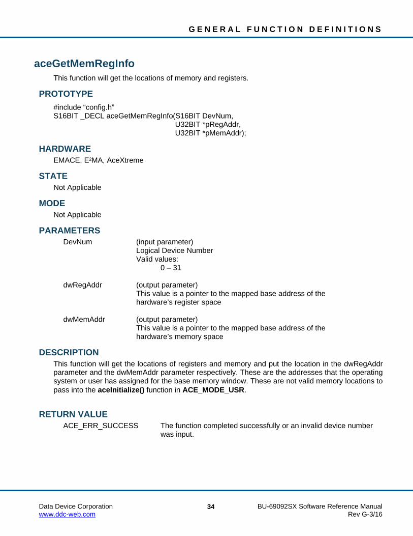
aceGetMemRegInfo This function will get the locations of memory and registers.
PROTOTYPE #include “config.h” S16BIT _DECL aceGetMemRegInfo(S16BIT DevNum, U32BIT *pRegAddr, U32BIT *pMemAddr);
HARDWARE EMACE, E²MA, AceXtreme
STATE Not Applicable
MODE Not Applicable
PARAMETERS DevNum (input parameter) Logical Device Number Valid values: 0 – 31 dwRegAddr (output parameter) This value is a pointer to the mapped base address of the hardware’s register space dwMemAddr (output parameter) This value is a pointer to the mapped base address of the hardware’s memory space
DESCRIPTION This function will get the locations of registers and memory and put the location in the dwRegAddr parameter and the dwMemAddr parameter respectively. These are the addresses that the operating system or user has assigned for the base memory window. These are not valid memory locations to pass into the aceInitialize() function in ACE_MODE_USR.
RETURN VALUE ACE_ERR_SUCCESS The function completed successfully or an invalid device number
was input.

G E N E R A L F U N C T I O N D E F I N I T I O N S
Data Device Corporation BU-69092SX Software Reference Manual www.ddc-web.com Rev G-3/16
35
aceGetMemRegInfo (continued) EXAMPLE
S16BIT DevNum = 0; S16BIT nResult = 0; U32BIT *pRegAddr; U32BIT *pMemAddr; nResult = aceGetMemRegInfo(DevNum, &pRegAddr, &pMemAddr); if (DevNum <0 || DevNum >31) { printf(“An invalid device number has been input \n”); } else { printf(“Function completed successfully \n”); }
SEE ALSO aceRegRead() aceRegWrite() aceMemRead() aceMemWrite() aceISQRead()

G E N E R A L F U N C T I O N D E F I N I T I O N S
Data Device Corporation BU-69092SX Software Reference Manual www.ddc-web.com Rev G-3/16
36
aceGetMsgTypeString This function will return the given message type string.
PROTOTYPE #include “MsgOp.h” char* _DECL aceGetMsgTypeString(U16BIT wMsgType);
HARDWARE EMACE, E²MA, AceXtreme
STATE Not Applicable
MODE Not Applicable
PARAMETERS wMsgType (input parameter) An U16BIT word representation of the message type Valid values: ACE_MSG_BCTORT (0) ACE_MSG_RTTOBC (1) ACE_MSG_ RTTORT (2) ACE_MSG_MODENODATA (5) ACE_MSG_MODEDATARX (6) ACE_MSG_MODEDATATX (7) ACE_MSG_BRDCST (8) ACE_MSG_BRDCSTRTTORT (10) ACE_MSG_BRDCSTMODENODATA (13) ACE_MSG_BRDCSTMODEDATA (14) ACE_MSG_ ACE_MSG_INVALID (15)
DESCRIPTION This function returns a pointer to a character buffer that will contain the given message type string.

G E N E R A L F U N C T I O N D E F I N I T I O N S
Data Device Corporation BU-69092SX Software Reference Manual www.ddc-web.com Rev G-3/16
37
aceGetMsgTypeString (continued) RETURN VALUE
Char * “BC to RT” "RT to BC" "RT to RT" "Invalid" "Mode No Data" "Mode Rx Data" "Mode Tx Data" "Bcst" "Bcst RT to RT" "Bcst Mode No Data" "Bcst Mode Data"
EXAMPLE Char *msg_type; msg_type = aceGetMsgTypeString(ACE_MSG_BCTORT); printf(“Message type %d = %s\n” ACE_MSG_BCTORT, msg_type);
SEE ALSO None

G E N E R A L F U N C T I O N D E F I N I T I O N S
Data Device Corporation BU-69092SX Software Reference Manual www.ddc-web.com Rev G-3/16
38
aceGetSWVersionInfo This function returns the software version number in a single structure.
PROTOTYPE #include “config.h” S16BIT _DECL aceGetSWVersionInfo (PSWVERSIONINFO pSwVersionInfo);
HARDWARE EMACE, E²MA, AceXtreme
STATE Ready, Run
MODE Not Applicable
PARAMETERS pSwVersionInfo (output parameter) Pointer to storage for a software version info structure
DESCRIPTION This function returns the software version number in a single structure of an E²MA device.
RETURN VALUE ACE_ERR_SUCCESS The function completed successfully ACE_ERR_PARAMETER Invalid parameter
EXAMPLE S16BIT nResult = 0; SWVERSIONINFO pSwVersionInfo; nResult = aceGetSWVersionInfo(&pSwVersionInfo); if (nResult < 0) { printf(“Error in aceGetSWVersionInfo() function \n”); PrintOutError (nResult); Return; }
SEE ALSO aceGetHWVersionInfo()

G E N E R A L F U N C T I O N D E F I N I T I O N S
Data Device Corporation BU-69092SX Software Reference Manual www.ddc-web.com Rev G-3/16
39
aceGetTimeTagValue This function retrieves the time tag value.
PROTOTYPE #include “config.h” S16BIT _DECL aceGetTimeTagValue(S16BIT DevNum, U16BIT *wTTValue);
HARDWARE EMACE, E²MA, AceXtreme
STATE Reset, Ready, Run
MODE Not Applicable
PARAMETERS DevNum (input parameter) Logical Device Number Valid values: 0 – 31 wTTValue (output parameter) Time Tag Value read from the register Valid values: 0x0000 – 0xFFFF
DESCRIPTION This function gets the value of the Time Tag Register in any state. This function will only return a 16-bit time tag, even on devices supporting 48-bit time tag. For devices supporting 48-bit time tags, see aceGetTimeTagValueEx().
RETURN VALUE ACE_ERR_INVALID_DEVNUM An invalid device number was input by the user ACE_ERR_SUCCESS The function completed successfully

G E N E R A L F U N C T I O N D E F I N I T I O N S
Data Device Corporation BU-69092SX Software Reference Manual www.ddc-web.com Rev G-3/16
40
aceGetTimeTagValue (continued) EXAMPLE
//To get the time tag value. S16BIT DevNum = 0; S16BIT nResult = 0; U16BIT pwTTValue; nResult = aceGetTimeTagValue (DevNum, &pwTTValue); if(nResult < 0) { printf(“Error in aceGetTimeTagValue() function \n”); PrintOutError(nResult); return; }
SEE ALSO aceGetTimeTagValueEx()

G E N E R A L F U N C T I O N D E F I N I T I O N S
Data Device Corporation BU-69092SX Software Reference Manual www.ddc-web.com Rev G-3/16
41
aceGetTimeTagValueEx This function retrieves the current value from the card’s 48-bit time tag register.
PROTOTYPE #include “config.h” S16BIT _DECL aceGetTimeTagValueEx(S16BIT DevNum, U64BIT* ullTTValue);
HARDWARE EMACE, E²MA, AceXtreme
STATE Ready, Run
MODE MT-I
PARAMETERS DevNum (input parameter) Logical Device Number Valid values: 0 – 31 UllTTValue Pointer to a variable of type U64BIT
DESCRIPTION This function returns the value of the 48-bit Time Tag Register in any state.
RETURN VALUE ACE_ERR_INVALID_DEVNUM An invalid device number was input ACE_ERR_SUCCESS The function completed successfully ACE_ERR_NOT_SUPPORTED Function not supported

G E N E R A L F U N C T I O N D E F I N I T I O N S
Data Device Corporation BU-69092SX Software Reference Manual www.ddc-web.com Rev G-3/16
42
aceGetTimeTagValueEx (continued) EXAMPLE
// To get the time tag value. S16BIT DevNum = 0; S16BIT nResult = 0; U64BIT llTTValue; nResult = aceGetTimeTagValueEx (DevNum, &llTTValue); if(nResult < 0) {
printf(“Error in aceGetTimeTagValueEx() function \n”); PrintOutError(nResult);
return; }
SEE ALSO aceSetTimeTagValueEx()

G E N E R A L F U N C T I O N D E F I N I T I O N S
Data Device Corporation BU-69092SX Software Reference Manual www.ddc-web.com Rev G-3/16
43
aceInitialize This function initializes hardware resources such as memory and register space for a particular mode of operation.
PROTOTYPE #include “config.h” S16BIT _DECL aceInitialize(S16BIT DevNum, 16BIT wAccess, U16BIT wMode, U32BIT dwMemWrdSize, U32BIT dwRegAddr, U32BIT dwMemAddr);
HARDWARE EMACE, E²MA, AceXtreme
STATE Reset, Ready
MODE Set by wMode parameter after this function is called.
PARAMETERS DevNum (input parameter) Logical Device Number Valid values: 0 - 31 wAccess (input parameter) This parameter specifies the type of access to be used by the device Valid values: ACE_ACCESS_CARD ACE_ACCESS_SIM (Not supported for AceXtreme) ACE_ACCESS_USR (Not supported for AceXtreme) wMode (input parameter) This parameter specifies the mode of operation that this device is to be initialized to. Valid Values: ACE_MODE_TEST Sets up the device to run in test mode. ACE_MODE_BC Sets up the device to run as a bus controller ACE_MODE_RT Sets up the device to run as a remote terminal ACE_MODE_MRT Sets up the device to for multiple remote terminals
G E N E R A L F U N C T I O N D E F I N I T I O N S
Data Device Corporation BU-69092SX Software Reference Manual www.ddc-web.com Rev G-3/16
44
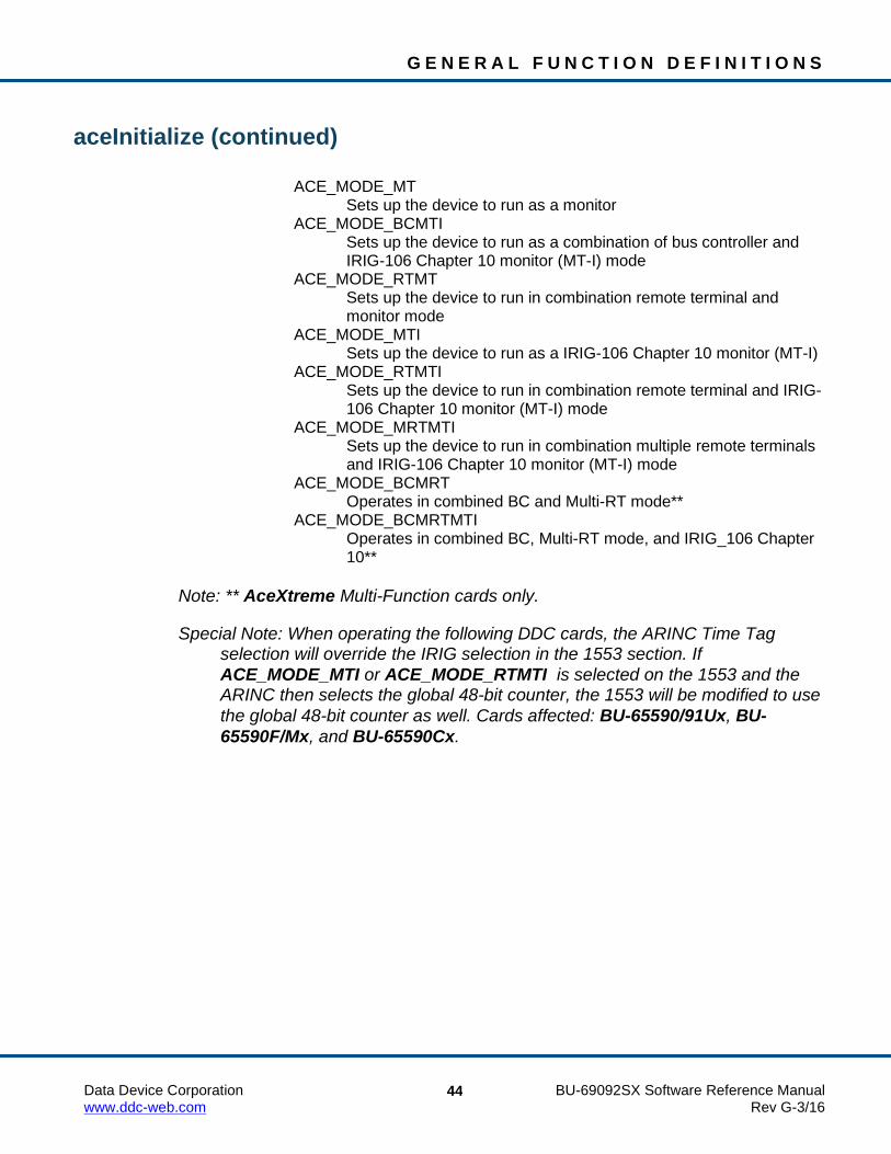
aceInitialize (continued) ACE_MODE_MT Sets up the device to run as a monitor ACE_MODE_BCMTI Sets up the device to run as a combination of bus controller and
IRIG-106 Chapter 10 monitor (MT-I) mode ACE_MODE_RTMT Sets up the device to run in combination remote terminal and
monitor mode ACE_MODE_MTI Sets up the device to run as a IRIG-106 Chapter 10 monitor (MT-I) ACE_MODE_RTMTI Sets up the device to run in combination remote terminal and IRIG-
106 Chapter 10 monitor (MT-I) mode ACE_MODE_MRTMTI Sets up the device to run in combination multiple remote terminals
and IRIG-106 Chapter 10 monitor (MT-I) mode ACE_MODE_BCMRT Operates in combined BC and Multi-RT mode** ACE_MODE_BCMRTMTI Operates in combined BC, Multi-RT mode, and IRIG_106 Chapter
10**
Note: ** AceXtreme Multi-Function cards only.
Special Note: When operating the following DDC cards, the ARINC Time Tag selection will override the IRIG selection in the 1553 section. If ACE_MODE_MTI or ACE_MODE_RTMTI is selected on the 1553 and the ARINC then selects the global 48-bit counter, the 1553 will be modified to use the global 48-bit counter as well. Cards affected: BU-65590/91Ux, BU-65590F/Mx, and BU-65590Cx.

G E N E R A L F U N C T I O N D E F I N I T I O N S
Data Device Corporation BU-69092SX Software Reference Manual www.ddc-web.com Rev G-3/16
45
aceInitialize (continued) The above inputs can be logically OR’ed with the following values: ACE_NO_TT_RESET Results in the time tag register never getting reset ACE_ADVANCED_MODE Advanced mode gives the user access to some advanced
functions, which are typically not needed if using this SDK to program a COTS 1553 card from DDC. In this mode of operation you have access to the following functions:
aceRegRead aceRegWrite aceMemRead aceMemWrite aceSetIrqConfig aceSetClockFreq aceSetAddressMode aceSetDecoderconfig wMemWrdSize (input parameter)
This parameter specifies the amount of ACE memory to be allocated for use when using the ACE_ACCESS_SIM or the ACE_ACCESS_USR access type, otherwise the value is not used
Valid Values: 4K - 64K dwRegAddr (input parameter) This parameter specifies the register address to be used by the device when the access type is selected to be ACE_ACCESS_USR dwMemAddr (input parameter) Base memory address for the device to use if the access type is selected to be ACE_ACCESS_USR
DESCRIPTION This function initializes hardware resources such as memory and register space for a particular mode of operation. The user can select the mode of operation with this function and the wMode parameter. The AceXtreme C SDK can be programmed using three methods of access: Simulated, Device, and User memory. Simulated memory allows the user to allocate a 4K to 64K chunk of host memory by using the malloc command and manipulate the memory as if it were hardware memory on the device until an image file is created. Simulated memory can be selected by inputting ACE_ACCESS_SIM into the wAccess parameter of this function. Device memory should be used if you are using a DDC card. This memory allows the memory on the device to be accessed through a device driver. This memory can be selected by inputting ACE_ACCESS_CARD into the wAccess parameter of this function.

G E N E R A L F U N C T I O N D E F I N I T I O N S
Data Device Corporation BU-69092SX Software Reference Manual www.ddc-web.com Rev G-3/16
46
aceInitialize (continued) User memory allows memory and register addresses to be passed directly to the SDK. User memory can be selected by inputting ACE_ACCESS_USR into the wAccess parameter of this function. Any access method can produce a binary image file but only the device memory access method (ACE_ACCESS_CARD) and the user memory access method (ACE_ACCESS_USR) can actually run the binary image file.
RETURN VALUE ACE_ERR_SUCCESS The device has been initialized successfully ACE_ERR_INVALID_DEVNUM An incorrect device number was input ACE_ERR_INVALID_ACCESS The access type specified is invalid ACE_ERR_INVALID_MODE The mode of operation selected is invalid ACE_ERR_INVALID_MEMSIZE The memory size specified in wMemWrdSize is not valid ACE_ERR_INVALID_ADDRESS One or all of the addresses specified in
dwRegAddr and dwMemAddr are invalid ACE_ERR_INVALID_MALLOC The proper amount of memory required for an Internal SDK
Information structure definition and initialization failed to be allocated
ACE_ERR_REG_ACCESS Failed to open the Operating System registry to get the device ID and logical device number
ACE_ERR_INVALID_CARD Card type is not recognized as a supported card ACE_ERR_INVALID_OS This operating system is not one of the following
supported types: Windows 2000/XP, Linux, or VxWorks ACE_ERR_DRIVER_OPEN Failed to open the device driver for this card
EXAMPLE S16BIT DevNum = 0; S16BIT nresult = 0; nResult = aceInitialize(DevNum,ACE_ACCESS_CARD,ACE_MODE_BC,0,0,0); if(nResult < 0) { //an error has occurred so notify the user printf(“Error in aceInitialize() function \n”); PrintOutError(nResult); return; }
SEE ALSO aceFree()

G E N E R A L F U N C T I O N D E F I N I T I O N S
Data Device Corporation BU-69092SX Software Reference Manual www.ddc-web.com Rev G-3/16
47
aceInt80Enable This function is used to turn on / off interrupts on a BU-65580 PC/104 EBR device.
PROTOTYPE #include “config.h” S16BIT _DECL aceInt80Enable(S16BIT DevNum, U16BIT bEnable) ;
HARDWARE BU-6558XCX PC/104 Card
STATE Ready
MODE RT, RTMT
PARAMETERS DevNum (input parameter) Logical Device Number Valid values: 0 – 31 bEnable (input parameter) Switch to enable / disable interrupts on the BU-65580 Valid values: FALSE This will disable interrupts TRUE This will enable interrupts
DESCRIPTION This function is used to turn interrupts on after the card is properly initialized. This function is called internally when the SDK has determined the proper initialization state has been reached. The aceInt80Enable function may also be called by the user if they wish to disable / enable a BU-65580 device’s interrupts on their own. This function is only used with the BU-6558xCx series of cards.
RETURN VALUE ACE_ERR_INVALID_DEVNUM An invalid device number was input by the user ACE_ERR_SUCCESS The function completed successfully

G E N E R A L F U N C T I O N D E F I N I T I O N S
Data Device Corporation BU-69092SX Software Reference Manual www.ddc-web.com Rev G-3/16
48
aceInt80Enable (continued) EXAMPLE
//Enable BU-65580 device #0’s interrupt nResult = aceInt80Enable (DevNum, TRUE);
SEE ALSO None
G E N E R A L F U N C T I O N D E F I N I T I O N S
Data Device Corporation BU-69092SX Software Reference Manual www.ddc-web.com Rev G-3/16
49
aceIOFree This function will be used to free any resources that were initialize using aceIOInitialize().
PROTOTYPE #include “Dio.h” S16BIT _DECL aceIOFree (S16BIT DevNum);
HARDWARE EMACE, E²MA, AceXtreme
STATE Ready, Run
MODE Not Applicable
PARAMETERS DevNum (input parameter) Logical Device Number Valid values: 0 – 31
DESCRIPTION This function will be used to free any resources that were initialized using aceIOInitialize() on an E²MA device.
RETURN VALUE ACE_ERR_SUCCESS The function completed successfully. ACE_ERR_INVALID_DEVNUM An invalid device number was used. ACE_ERR_INVALID_STATE Device is not in Ready or Run State. ACE_INVALID_CARD Device does not support this function. ACE_ERR_INVALID_CARD Function not supported be device

G E N E R A L F U N C T I O N D E F I N I T I O N S
Data Device Corporation BU-69092SX Software Reference Manual www.ddc-web.com Rev G-3/16
50
aceIOFree (continued) EXAMPLE
S16BIT DevNum = 0; S16BIT nResult = 0; nResult = aceIOFree (DevNum); if (nResult < 0) { printf(“Error in aceIOFree()function \n”); PrintOutError (nResult); return; }
SEE ALSO aceIOInitialize()

G E N E R A L F U N C T I O N D E F I N I T I O N S
Data Device Corporation BU-69092SX Software Reference Manual www.ddc-web.com Rev G-3/16
51
aceIOInitialize This function will initialize the resources so that I/O can be performed independent of the 1553 functions.
PROTOTYPE #include “Dio.h” S16BIT _DECL aceIOInitialize (S16BIT DevNum, S16BIT wOptions);
HARDWARE EMACE, E²MA, AceXtreme
STATE Ready, Run
MODE Not Applicable
PARAMETERS DevNum (input parameter) Logical Device Number Valid values: 0 – 31 wOptions (input parameter) Future use
DESCRIPTION This function will initialize the resources so that I/O can be performed independent of the 1553 functions on an E²MA device.
RETURN VALUE ACE_ERR_SUCCESS The function completed successfully ACE_ERR_INVALID_DEVNUM An invalid device number was used ACE_ERR_INVALID_STATE Device is not in Ready or Run State ACE_INVALID_CARD Device does not support this function ACE_ERR_REG_ACCESS Failed to open the Operating System registry to get the
device ID and logical device number ACE_ERR_DRIVER_OPEN Failed to open the device driver for this card

G E N E R A L F U N C T I O N D E F I N I T I O N S
Data Device Corporation BU-69092SX Software Reference Manual www.ddc-web.com Rev G-3/16
52
aceIOInitialize (continued) EXAMPLE
S16BIT DevNum = 0; S16BIT nResult = 0; S16BIT wOptions = 0; nResult = aceIOInitialize(DevNum, wOptions); if (nResult < 0) { printf(“Error in aceIOInitialize()function \n”); PrintOutError (nResult); return; }
SEE ALSO aceIOFree()

G E N E R A L F U N C T I O N D E F I N I T I O N S
Data Device Corporation BU-69092SX Software Reference Manual www.ddc-web.com Rev G-3/16
53
aceISQClear This function clears the ISQ.
PROTOTYPE #include “config.h” S16BIT _DECL aceISQRead(S16BIT DevNum);
HARDWARE EMACE, E²MA, AceXtreme
STATE Ready, Run
MODE MT, RT, RTMT
PARAMETERS DevNum (input parameter) Logical Device Number Valid values: 0 – 31
DESCRIPTION This function clears all values on the ISQ and resets the pointer register to the starting position queue. The return value will report the success of the operation.
RETURN VALUE ACE_ERR_ISQ_DISABLED The Interrupt Status Queue is disabled and must be
enabled by calling the aceISQEnable() function before calling this function
ACE_ERR_INVALID_DEVNUM An invalid device number was input to this function ACE_ERR_INVALID_MODE The device is not in MT, RT, or RTMT mode ACE_ERR_INVALID_STATE The device is not in the Ready or Run state ACE_ERR_SUCCESS The function completed successfully
G E N E R A L F U N C T I O N D E F I N I T I O N S
Data Device Corporation BU-69092SX Software Reference Manual www.ddc-web.com Rev G-3/16
54
aceISQClear (continued) EXAMPLE
S16BIT DevNum = 0; S16BIT nResult = 0; nResult = aceISQClear(DevNum); if(nResult < 0) { printf(“Error in aceISQClear() function \n”); aceErrorStr(nResult, Buffer, 80); printf("SDK Function Failure-> %s.\n",pBuffer); }
SEE ALSO aceISQEnable() aceISQRead()

G E N E R A L F U N C T I O N D E F I N I T I O N S
Data Device Corporation BU-69092SX Software Reference Manual www.ddc-web.com Rev G-3/16
55
aceISQEnable This function allows the user to enable or disable the Interrupt Status Queue.
PROTOTYPE #include “config.h” S16BIT _DECL aceISQEnable(S16BIT DevNum, U16BIT bEnable);
HARDWARE EMACE, E²MA, AceXtreme
STATE Ready
MODE RT, RTMT
PARAMETERS DevNum (input parameter) Logical Device Number Valid values: 0 – 31 bEnable (input parameter) FALSE This will disable the interrupt status queue TRUE This will enable the interrupt status queue
DESCRIPTION This function enables the interrupt status queue for the user to utilize in RT or RTMT mode of operation. The interrupt status queue can also be disabled with this function but is disabled by default, so there is no need to call this function if you do not wish to use the interrupt status queue.
RETURN VALUE ACE_ERR_SUCCESS The function completed successfully ACE_ERR_INVALID_DEVNUM An invalid device number was input to this function ACE_ERR_INVALID_MODE The device is not in RT, or RTMT mode ACE_ERR_INVALID_STATE The device is not in the Ready state ACE_WRN_RT_CFG_INVALID Operation of your device may be problematic
because one or more of the following interrupts have been enabled: Time Tag Rollover, RT Address Parity Error, and/or Ram Parity Error along with the Interrupt Status Queue. See Appendix B for details

G E N E R A L F U N C T I O N D E F I N I T I O N S
Data Device Corporation BU-69092SX Software Reference Manual www.ddc-web.com Rev G-3/16
56
aceISQEnable (continued) EXAMPLE
S16BIT DevNum = 0; S16BIT nResult = 0; nResult = aceISQEnable(DevNum, TRUE); if (nResult < 0) { PrintOutError(nResult); return; } else { printf(“The function completed successfully \n”); }
SEE ALSO aceISQClear() aceISQRead()

G E N E R A L F U N C T I O N D E F I N I T I O N S
Data Device Corporation BU-69092SX Software Reference Manual www.ddc-web.com Rev G-3/16
57
aceISQRead This function reads the next unread entry off of the interrupt status queue.
PROTOTYPE #include “config.h” S16BIT _DECL aceISQRead(S16BIT DevNum, ISQENTRY *pISQEntry);
HARDWARE EMACE, E²MA, AceXtreme
STATE Ready, Run
MODE MT, RT, RTMT
PARAMETERS DevNum (input parameter) Logical Device Number Valid values: 0 – 31 pISQEntry (output parameter) Pointer to the entry read off of the interrupt status queue
DESCRIPTION This function reads the next unread entry off of the interrupt status queue. The return value will report the success of the operation.
RETURN VALUE ACE_ERR_INVALID_DEVNUM An invalid device number was input to this function ACE_ERR_INVALID_MODE The device is not in MT, RT, or RTMT mode ACE_ERR_INVALID_STATE The device is not in the Ready or Run state ACE_ERR_PARAMETER The pISQEntry parameter is NULL ACE_ERR_ISQ_DISABLED The Interrupt Status Queue is disabled and must be
enabled by calling the aceISQEnable() function before calling this function
0 (zero) No entries were read off of the interrupt status queue 1 (one) One entry was read off of the interrupt status queue 2 (two) One entry was read off of the interrupt status queue
with an overrun condition

G E N E R A L F U N C T I O N D E F I N I T I O N S
Data Device Corporation BU-69092SX Software Reference Manual www.ddc-web.com Rev G-3/16
58
aceISQRead (continued) EXAMPLE
S16BIT DevNum = 0; ISQENTRY *pISQEntry; S16BIT nResult = 0; nResult = aceISQRead(DevNum, &pISQEntry); if (nResult < 0) { PrintOutError(nResult); return; } else if (nResult == 0) { printf(“No entries were read from the ISQ \n”); } else if (nResult == 1) { printf(“One entry was successfully read from the ISQ \n”); } else if (nResult == 2) { printf(“One entry was read from the ISQ with overrun cond. \n”); } else { printf(“An undefined error occurred \n”); }
SEE ALSO aceISQEnable() aceISQClear()

G E N E R A L F U N C T I O N D E F I N I T I O N S
Data Device Corporation BU-69092SX Software Reference Manual www.ddc-web.com Rev G-3/16
59
aceMemRead This function reads memory.
PROTOTYPE #include “config.h” U16BIT _DECL aceMemRead(S16BIT DevNum, U16BIT wMemAddr);
HARDWARE EMACE, E²MA, AceXtreme
STATE Ready if not in advanced mode of operation Any state if in advanced mode of operation
MODE Advanced plus one of the following: BC, RT, MT, RTMT
PARAMETERS DevNum (input parameter) Logical Device Number Valid values: 0 – 31 wMemAddr (input parameter) This parameter specifies the memory location to be read
DESCRIPTION This function reads the memory location specified by the wMemAddr input parameter. This function is available for the advanced user that would like to know the contents of a hardware memory location, and can only be used while in the ready state if the AceXtreme C SDK is not in advanced mode of operation. If the SDK is in advanced mode of operation then this function can be called in any state.
RETURN VALUE 0x0000 – 0xFFFF The contents of the memory location that was read 0 An invalid device number, and/or the device is not in a Ready state,
and/or the wMemAddr is invalid

G E N E R A L F U N C T I O N D E F I N I T I O N S
Data Device Corporation BU-69092SX Software Reference Manual www.ddc-web.com Rev G-3/16
60
aceMemRead (continued) EXAMPLE
S16BIT DevNum = 0; U16BIT wMemAddr = 0x03; U16BIT wMemValue = 0; wMemValue = aceMemRead(DevNum, wMemAddr); printf(“Memory location %x \n”, wMemAddr); if (wMemValue != 0) { printf(“contains the following value: %x”, wMemValue); } else { printf(“The function returned an error or memory contained 0’s”); }
SEE ALSO aceRegRead() aceRegWrite() aceMemWrite() aceGetMemRegInfo() aceISQRead()

G E N E R A L F U N C T I O N D E F I N I T I O N S
Data Device Corporation BU-69092SX Software Reference Manual www.ddc-web.com Rev G-3/16
61
aceMemRead32 This function reads memory.
PROTOTYPE #include “config.h” U32BIT _DECL aceMemRead32(S16BIT DevNum, U32BIT dwMemAddr);
HARDWARE E²MA, AceXtreme
STATE Ready if not in advanced mode of operation Any state if in advanced mode of operation
MODE BC, RT, MT, RTMT, MT-I, RTMT-I
PARAMETERS DevNum (input parameter) Logical Device Number Valid Values: 0 – 31 dwMemAddr (input parameter) 32-bit Address of the memory to read
DESCRIPTION This function reads the memory location specified by the wMemAddr input parameter. This function is available for the advanced user that would like to know the contents of a hardware memory location, and can only be used while in the ready state if the AceXtreme C SDK is not in advanced mode of operation. If the SDK is in advanced mode of operation then this function can be called in any state.
RETURN VALUE 0x00000000 – 0xFFFFFFFF The contents of the register that was read 0 An invalid device number, and/or the wRegAddr parameter
is greater than 63, and/or the device is not in a Ready state

G E N E R A L F U N C T I O N D E F I N I T I O N S
Data Device Corporation BU-69092SX Software Reference Manual www.ddc-web.com Rev G-3/16
62
aceMemRead32 (continued) EXAMPLE
//The following example will read Configuration Reg. #2 S16BIT DevNum = 0; U32BIT dwMemAddr = 0x0002; U32BIT dwReturn = 0; dwReturn = aceMemRead32(DevNum, dwMemAddr); printf(“Memory location %x \n”, dwMemAddr); if (dwReturn!=0) { printf(“Contains the following value: %x \n, dwReturn); } else { printf(“The Memory location is all zeros or an error occurred \n”); }
SEE ALSO aceRegRead32() aceRegWrite32() aceMemWrite32()

G E N E R A L F U N C T I O N D E F I N I T I O N S
Data Device Corporation BU-69092SX Software Reference Manual www.ddc-web.com Rev G-3/16
63
aceMemWrite This function writes to a specified memory location.
PROTOTYPE #include “config.h” S16BIT _DECL aceMemWrite(S16BIT DevNum, U16BIT wMemAddr, U16BIT wValue);
HARDWARE EMACE, E²MA, AceXtreme
STATE Ready if not in advanced mode of operation Any state if in advanced mode of operation
MODE Advanced plus one of the following: BC, RT, MT, RTMT
PARAMETERS DevNum (input parameter) Logical Device Number Valid values: 0 – 31 wMemAddr (input parameter) This parameter specifies the memory location to write to wValue (input parameter) This is the value to be written to the memory location Valid values: 0x0000 – 0xFFFF
DESCRIPTION This function writes a 16-bit value input by the user to a specified memory location on the device. This function is available for the advanced user that would like to write the contents of a hardware memory location, and can only be used while in the ready state if the AceXtreme C SDK is not in advanced mode of operation. If the SDK is in advanced mode of operation, then this function can be called in any state. Caution must be taken as to not write invalid data to a memory address and corrupt the operation of the device.
RETURN VALUE ACE_ERR_SUCCESS The function completed successfully ACE_ERR_INVALID_DEVNUM An invalid device number was input to this function ACE_ERR_INVALID_STATE The device is not in a Ready state and the function
could not be completed

G E N E R A L F U N C T I O N D E F I N I T I O N S
Data Device Corporation BU-69092SX Software Reference Manual www.ddc-web.com Rev G-3/16
64
aceMemWrite (continued) ACE_ERR_INVALID_ADDRESS An invalid memory address was input to this function ACE_ERR_NOT_SUPPORTED This function can only be used in Advanced mode
of operation unless you are in a Ready state
EXAMPLE S16BIT DevNum = 0; U16BIT wMemAddr = 0x02; U16BIT wValue = 0xFFFF; S16BIT nResult = 0; nResult = aceMemWrite(DevNum, wMemAddr, wValue); if(nResult < 0) {
printf(“Error in aceMemWrite() function \n”); PrintOutError(nResult); return; }
SEE ALSO aceRegRead() aceRegWrite() aceMemRead() aceGetMemRegInfo() aceISQRead()

G E N E R A L F U N C T I O N D E F I N I T I O N S
Data Device Corporation BU-69092SX Software Reference Manual www.ddc-web.com Rev G-3/16
65
aceMemWrite32 This function will write to the specified register location.
PROTOTYPE #include “config.h” U32BIT _DECL aceMemWrite32(S16BIT DevNum, U32BIT dwMemAddr, U32BIT dwValue);
HARDWARE E²MA, AceXtreme
STATE Ready if not in advanced mode of operation Any state if in advanced mode of operation
MODE BC, RT, MT, RTMT, MT-I, RTMT-I
PARAMETERS DevNum (input parameter) Logical Device Number Valid Values: 0 – 31 dwMemAddr (input parameter) 32-bit Address of the memory to read DwValue (input parameter) Value to be written to dwMemAddr
0x00000000 – 0xFFFFFFFF
DESCRIPTION This function writes a 32-bit value input by the user to a specified memory location on the device. This function is available for the advanced user that would like to write the contents of a hardware memory location, and can only be used while in the ready state if AceXtreme C SDK is not in advanced mode of operation. If the SDK is in advanced mode of operation, then this function can be called in any state. Caution must be taken as to not write invalid data to a memory address and corrupt the operation of the device.

G E N E R A L F U N C T I O N D E F I N I T I O N S
Data Device Corporation BU-69092SX Software Reference Manual www.ddc-web.com Rev G-3/16
66
aceMemWrite32 (continued) RETURN VALUE
ACE_ERR_SUCCESS The function completed successfully ACE_ERR_INVALID_DEVNUM An invalid device number was entered ACE_ERR_INVALID_STATE The device is not in a Ready state ACE_ERR_INVALID_ADDRESS An invalid register address was entered ACE_ERR_NOT_SUPPORTED This function can only be used in Advanced mode of
operation unless you are in a Ready state
EXAMPLE S16BIT DevNum = 0; U32BIT dwMemAddr = 0x02; U32BIT dwValue = 0x08000000; S16BIT nResult = 0; nResult = aceMemWrite32(DevNum, dwMemAddr, dwValue); if(nResult < 0) { printf(“Error in aceMemWrite32() function \n”); PrintOutError(nResult); return; }
SEE ALSO aceRegRead32() aceRegWrite32() aceMemRead32()

G E N E R A L F U N C T I O N D E F I N I T I O N S
Data Device Corporation BU-69092SX Software Reference Manual www.ddc-web.com Rev G-3/16
67
aceRegRead This function reads a register on the device at the specified memory location.
PROTOTYPE #include “config.h” U16BIT _DECL aceRegRead(S16BIT DevNum, U16BIT wRegAddr);
HARDWARE EMACE, E²MA, AceXtreme
STATE Ready if not in advanced mode of operation Any state if in advanced mode of operation
MODE Advanced plus one of the following: BC, RT, MT, RTMT
PARAMETERS DevNum (input parameter) Logical Device Number Valid values: 0 – 31 wRegAddr (input parameter) This parameter specifies the register address to be read
DESCRIPTION This function reads a register on the device at the specified memory location. This function should be used when the user would like to know the contents of a specific hardware register. This function is available for the advanced user that would like to know the contents of the hardware registers, and can only be used while in the ready state if the AceXtreme C SDK is not in advanced mode of operation. If the SDK is in advanced mode of operation then this function can be called in any state.
RETURN VALUE 0x0000 – 0xFFFF The contents of the register that was read 0 An invalid device number, and/or the wRegAddr
parameter is greater than 63, and/or the device is not in a Ready state

G E N E R A L F U N C T I O N D E F I N I T I O N S
Data Device Corporation BU-69092SX Software Reference Manual www.ddc-web.com Rev G-3/16
68
aceRegRead (continued) EXAMPLE
//The following example will read Configuration Reg. #2 S16BIT DevNum = 0; U16BIT wRegContents = 0; U16BIT wRegAddr = 0x02; wRegContents = aceRegRead(DevNum, wRegAddr); printf(“Register %x \n”, wRegAddr); if (wRegContents!=0) { printf(“Contains the following value: %x \n, wRegContents); } else { printf(“The register is all zeros or an error occurred \n”); }
SEE ALSO aceRegWrite() aceMemRead() aceMemWrite() aceGetMemRegInfo() aceISQRead()

G E N E R A L F U N C T I O N D E F I N I T I O N S
Data Device Corporation BU-69092SX Software Reference Manual www.ddc-web.com Rev G-3/16
69
aceRegRead32 This function reads a register on the device at the specified memory location.
PROTOTYPE #include “config.h” U32BIT _DECL aceRegRead32(S16BIT DevNum, U16BIT wRegAddr);
HARDWARE E²MA, AceXtreme
STATE Ready if not in advanced mode of operation Any state if in advanced mode of operation
MODE BC,RT, MT, RTMT, MT-I, RTMT-I
PARAMETERS DevNum (input parameter) Logical Device NumberValid Values: 0 – 31 wRegAddr (input parameter) Address of the register to read
DESCRIPTION This function reads a register on the device at the specified memory location. This function should be used when the user would like to know the contents of a specific hardware register. This function is available for the advanced user that would like to know the contents of the hardware registers, and can only be used while in the ready state if the AceXtreme C SDK is not in advanced mode of operation. If the SDK is in advanced mode of operation, then this function can be called in any state.
RETURN VALUE 0x0000 – 0xFFFF The contents of the register that was read 0 An invalid device number, and/or the wRegAddr parameter is
greater than 63, and /or the device is not in a Ready state

G E N E R A L F U N C T I O N D E F I N I T I O N S
Data Device Corporation BU-69092SX Software Reference Manual www.ddc-web.com Rev G-3/16
70
aceRegRead32 (continued) EXAMPLE
//The following example will read Configuration Reg. #2 S16BIT DevNum = 0; U32BIT dwRegContents = 0; U16BIT dwRegAddr = 0x02; dwRegContents = aceRegRead32(DevNum, wRegAddr); printf(“Register %x \n”, wRegAddr); if (dwRegContents!=0) { printf(“Contains the following value: %x \n, dwRegContents); } else { printf(“The register is all zeros or an error occurred \n”); }
SEE ALSO aceRegWrite32() aceMemRead32() aceMemWrite32()

G E N E R A L F U N C T I O N D E F I N I T I O N S
Data Device Corporation BU-69092SX Software Reference Manual www.ddc-web.com Rev G-3/16
71
aceRegWrite This function will write to the specified register location.
PROTOTYPE #include “config.h” S16BIT _DECL aceRegWrite(S16BIT DevNum, U16BIT wRegAddr, U16BIT wValue);
HARDWARE EMACE, E²MA, AceXtreme
STATE Ready if not in advanced mode of operation Any state if in advanced mode of operation
MODE Advanced plus one of the following: BC, RT, MT, RTMT
PARAMETERS DevNum (input parameter) Logical Device Number Valid values: 0 – 31 wRegAddr (input parameter) This parameter specifies the register to write to wValue (input parameter) The value that should be written to the register Valid values: 0x0000 – 0xFFFF
DESCRIPTION This function will write to the specified register location. This function should be used when data must be written to a specific hardware register that the user is concerned with. This function is available for the advanced user that would like to write the contents of the hardware registers, and can only be used while in the ready state if the AceXtreme C SDK is not in advanced mode of operation. If the SDK is in advanced mode of operation, then this function can be called in any state.

G E N E R A L F U N C T I O N D E F I N I T I O N S
Data Device Corporation BU-69092SX Software Reference Manual www.ddc-web.com Rev G-3/16
72
aceRegWrite (continued) RETURN VALUE
ACE_ERR_SUCCESS The function completed successfully ACE_ERR_INVALID_DEVNUM An invalid device number was input to this function ACE_ERR_INVALID_STATE The device is not in a Ready state ACE_ERR_INVALID_ADDRESS An invalid register address was input ACE_ERR_NOT_SUPPORTED This function can only be used in Advanced mode
of operation unless you are in a Ready state
EXAMPLE S16BIT DevNum = 0; U16BIT wRegAddr = 0x02; U16BIT wValue = 0x0800; S16BIT nResult = 0; nResult = aceRegWrite(DevNum, wRegAddr, wValue); if(nResult < 0) { printf(“Error in aceRegWrite() function \n”); PrintOutError(nResult); return; }
SEE ALSO aceRegRead() aceMemRead() aceMemWrite() aceGetMemRegInfo() aceISQRead()

G E N E R A L F U N C T I O N D E F I N I T I O N S
Data Device Corporation BU-69092SX Software Reference Manual www.ddc-web.com Rev G-3/16
73
aceRegWrite32 This function will write to the specified register location.
PROTOTYPE #include “config.h” U32BIT _DECL aceRegWrite32(S16BIT DevNum, U16BIT wRegAddr, U32BIT dwValue);
HARDWARE E²MA, AceXtreme
STATE Ready if not in advanced mode of operation Any state if in advanced mode of operation
MODE BC, RT, MT, RTMT, MT-I, RTMT-I
PARAMETERS DevNum (input parameter) Logical Device Number Valid Values: 0 – 31 wRegAddr (input parameter) Address of the register to read
dwValue (input parameter) Value to be written to wRegAddr.
0x00000000 – 0xFFFFFFFF
DESCRIPTION This function will write to the specified register location. This function should be used when data must be written to a specific hardware register that the user is concerned with. This function is available for the advanced user that would like to write the contents of the hardware register, and can only be used while in the ready state if the AceXtreme C SDK is not in advanced mode of operation. If the SDK is in advanced mode of operation, then this function can be called in any state.

G E N E R A L F U N C T I O N D E F I N I T I O N S
Data Device Corporation BU-69092SX Software Reference Manual www.ddc-web.com Rev G-3/16
74
aceRegRead32 (continued) RETURN VALUE
ACE_ERR_SUCCESS The function completed successfully ACE_ERR_INVALID_DEVNUM An invalid device number was entered ACE_ERR_INVALID_STATE The device is not in a Ready state ACE_ERR_INVALID_ADDRESS An invalid register address was entered ACE_ERR_NOT_SUPPORTED This function can only be used in Advanced mode
of operation unless you are in a Ready state.
EXAMPLE S16BIT DevNum = 0; U16BIT wRegAddr = 0x02; U32BIT dwValue = 0x08000000; S16BIT nResult = 0; nResult = aceRegWrite32(DevNum, wRegAddr, dwValue); if(nResult < 0) { printf(“Error in aceRegWrite32() function \n”); PrintOutError(nResult); return; }
SEE ALSO aceRegRead32() aceMemRead32() aceMemWrite32()

G E N E R A L F U N C T I O N D E F I N I T I O N S
Data Device Corporation BU-69092SX Software Reference Manual www.ddc-web.com Rev G-3/16
75
aceResetTimeTag This function allows the user to reset the value of the Time Tag Register to 0x0000.
PROTOTYPE #include “config.h” S16BIT _DECL aceResetTimeTag (S16BIT DevNum);
HARDWARE EMACE, E²MA, AceXtreme
STATE Reset, Ready, Run
MODE Not Applicable
PARAMETERS DevNum (input parameter) Logical Device Number Valid values: 0 – 31
DESCRIPTION This function accesses bit 3 of the Start/Reset Register, which causes the value of the Time Tag Register to reset to zero (0x0000).
RETURN VALUE ACE_ERR_SUCCESS The function completed successfully ACE_ERR_INVALID_DEVNUM An invalid device number was input by the user
EXAMPLE //To reset the time tag register to 0x0000.
S16BIT DevNum = 0; S16BIT nResult = 0; nResult = aceResetTimeTag (DevNum); if(nResult < 0) {
printf(“Error in aceResetTimeTag() function \n”); PrintOutError(nResult); return; }
SEE ALSO None

G E N E R A L F U N C T I O N D E F I N I T I O N S
Data Device Corporation BU-69092SX Software Reference Manual www.ddc-web.com Rev G-3/16
76
aceSetAddressMode This function defines the word addressing based on the host computer architecture.
PROTOTYPE #include “config.h” S16BIT _DECL aceSetAddressMode(S16BIT DevNum, U16BIT wAddrMode);
HARDWARE EMACE, E²MA, AceXtreme
STATE Ready
MODE Advanced plus one of the following BC, RT, MT, RTMT
PARAMETERS DevNum (input parameter) Logical Device Number Valid values: 0 – 31 wAddrMode (input parameter) Defines hardware address mode Valid values: ACE_ADDRMODE_A0_A0 ACE_ADDRMODE_A1_A0 ACE_ADDRMODE_A2_A0
DESCRIPTION This function sets the way in which hardware registers and memory will be addressed. It is important to note that with respect to the hardware’s address bus all internal address mapping is word orientated rather than byte orientated. Most standard microprocessors are byte orientated. This difference must be taken into account and is handled internally in this SDK by calling this function. The default mode (ACE_ADDRMODE_A1_A0) assumes that the host’s microprocessor is byte orientated so it will take two increments of the host’s address to access the next word location on the 1553 hardware. The valid values for wAddrMode are: ACE_ADDRMODE_A0_A0 - Incrementing the host address by 1 will access the next word on the hardware. ACE_ADDRMODE_A1_A0 - (Default) Incrementing the host address by 2 will access the next word on the hardware. ACE_ADDRMODE_A2_A0 - Incrementing the host address by 4 will access the next word on the hardware.

G E N E R A L F U N C T I O N D E F I N I T I O N S
Data Device Corporation BU-69092SX Software Reference Manual www.ddc-web.com Rev G-3/16
77
aceSetAddressMode (continued) For users running an on a DDC COTS card product, there is no need to call this function. This function is only available in advanced mode of operations for those that are designing their own system or card.
RETURN VALUE ACE_ERR_SUCCESS The function completed successfully ACE_ERR_INVALID_DEVNUM An invalid device number was input to this function ACE_ERR_INVALID_STATE The device is not in a Ready state ACE_ERR_INVALID_ADMODE The wAddrMode input parameter contains an
incorrect value ACE_ERR_NOT_SUPPORTED This function can only be used in Advanced mode
of operation
EXAMPLE S16BIT DevNum = 0; S16BIT nResult = 0; nResult = aceSetAddressMode(DevNum, ACE_ADDRMODE_A2_A0); if(nResult < 0) { //an error has occurred so notify the user printf(“Error in aceSetAddressMode() function \n”); PrintOutError(nResult); return; }
SEE ALSO None

G E N E R A L F U N C T I O N D E F I N I T I O N S
Data Device Corporation BU-69092SX Software Reference Manual www.ddc-web.com Rev G-3/16
78
aceSetAsyncIsr This function sets the interrupt handler to be used when a high priority asynchronous message violates the minor frame time.
PROTOTYPE #include “config.h” S16BIT _DECL aceSetAsyncIsr(S16BIT DevNum, void(_DECL *funcAsyncIsr)(S16BIT DevNum, U16BIT wMnrFrmId));
HARDWARE EMACE, E²MA
STATE Ready
MODE Not Applicable
PARAMETERS DevNum (input parameter) Logical Device Number Valid values: 0 – 31 funcAsyncIsr (input parameter) Pointer to an interrupt service routine function to call when a high priority asynchronous message violates the minor frame time.
DESCRIPTION This function sets the interrupt handler to be used when a high priority asynchronous message violates the minor frame time.
RETURN VALUE ACE_ERR_SUCCESS The function completed successfully ACE_ERR_INVALID_DEVNUM An invalid device number was input to this function ACE_ERR_INVALID_STATE The device is not in a Ready state and the function
could not be completed ACE_ERR_INVALID_ACCESS The device is not a card because it is not in
ACE_ACCESS_CARD mode set by the aceInitialize() function

G E N E R A L F U N C T I O N D E F I N I T I O N S
Data Device Corporation BU-69092SX Software Reference Manual www.ddc-web.com Rev G-3/16
79
aceSetAsyncIsr (continued) EXAMPLE
S16BIT DevNum = 0; S16BIT nResult = 0; //user defined callback function (myISR) sample void _DECL myISR (S16BIT DevNum, U16BIT wMnrFrmId) { //ISR implementation user defined callback routine printf(“An interrupt has occurred \n”); } nResult = aceSetAsyncIsr(DevNum, myIsr); if (nResult < 0) { printf(“Error in aceSetAsyncIsr() function \n”); PrintOutError (nResult); return; }
SEE ALSO None

G E N E R A L F U N C T I O N D E F I N I T I O N S
Data Device Corporation BU-69092SX Software Reference Manual www.ddc-web.com Rev G-3/16
80
aceSetCanIsr This function is used to turn on / off interrupts on a BU-65580 PC/104 EBR device.
PROTOTYPE #include “config.h” S16BIT _DECL aceSetCanIsr(S16BIT DevNum, void(_DECL *funcCANIsr)(S16BIT DevNum, U16BIT wIrqStatus));
HARDWARE BU-6558XCX PC/104 Card
STATE Ready
MODE Not Applicable
PARAMETERS DevNum (input parameter) Logical Device Number Valid values: 0 – 31 funcCANIsr (input parameter) Pointer to function handle for CAN interrupts.
DESCRIPTION This function is used to assign a user interrupt handler to any received CANbus interrupt. This function is only used with the BU-6558xCx series of cards.
RETURN VALUE ACE_ERR_SUCCESS The function completed successfully ACE_ERR_INVALID_DEVNUM An invalid device number was input to this function ACE_ERR_INVALID_STATE The device is not in a Ready state and the function
could not be completed ACE_ERR_PARAMETER The designated funcCANIsr contains an invalid handle ACE_ERR_INVALID_CARD The device being assigned an ISR is not one of the BU-
6558xCx series of cards

G E N E R A L F U N C T I O N D E F I N I T I O N S
Data Device Corporation BU-69092SX Software Reference Manual www.ddc-web.com Rev G-3/16
81
aceSetCanIsr (continued) EXAMPLE
S16BIT DevNum = 0; S16BIT nResult = 0; //user defined callback function (myISR) sample void _DECL myISR (S16BIT DevNum, U16BIT Status) { //ISR implementation user defined callback routine printf(“An interrupt has occurred \n”); } nResult = aceSetCanIsr(DevNum, myIsr); if (nResult < 0) { printf(“Error in aceSetCanIsr() function \n”); PrintOutError (nResult); return; }
SEE ALSO None

G E N E R A L F U N C T I O N D E F I N I T I O N S
Data Device Corporation BU-69092SX Software Reference Manual www.ddc-web.com Rev G-3/16
82
aceSetClockFreq This function sets the expected hardware clock input frequency.
PROTOTYPE #include “config.h” S16BIT _DECL aceSetClockFreq(S16BIT DevNum, U16BIT wClockIn);
HARDWARE EMACE, E²MA
STATE Ready
MODE Advanced plus one of the following: BC, RT, MT, RTMT
PARAMETERS DevNum (input parameter) Logical Device Number Valid values: 0 – 31 wClockIn (input parameter) Defines the clock frequency input Valid Values: ACE_CLOCK_16MHZ ACE_CLOCK_12MHZ ACE_CLOCK_20MHZ ACE_CLOCK_10MHZ
DESCRIPTION This function sets the type of clock input the hardware should be expecting. The valid values for wClockIn are: Legacy Mode and Enhanced Mini-ACE Mode: ACE_CLOCK_16MHZ -> Clock running at 16 MHz ACE_CLOCK_12MHZ -> Clock running at 12 MHz Enhanced Mini-ACE Mode Only: ACE_CLOCK_20MHZ -> Clock running at 20 MHz ACE_CLOCK_10MHZ -> Clock running at 10 MHz For card level products, the default clock frequency is 16 MHz and is set up when you configure a BC, RT, or MT for operation. This clock should not be changed if you are using a card level product. To use this function you must be in advanced mode of operation.

G E N E R A L F U N C T I O N D E F I N I T I O N S
Data Device Corporation BU-69092SX Software Reference Manual www.ddc-web.com Rev G-3/16
83
aceSetClockFreq (continued) RETURN VALUE
ACE_ERR_SUCCESS The function completed successfully ACE_ERR_INVALID_DEVNUM An invalid device number was input to this function ACE_ERR_INVALID_STATE The device is in not in a Ready state and this
function could not complete ACE_ERR_CLOCKIN The device is in legacy mode and you have
selected the clock frequency to be either 10 MHz or 20 MHz ACE_ERR_NOT_SUPPORTED This function can only be used in Advanced mode
of operation
EXAMPLE /* Assign 16Mhz to the clock input. */
S16BIT DevNum = 0; S16BIT nResult = 0; nresult = aceSetClockFreq(DevNum, ACE_CLOCK_16MHz); if(nResult < 0) { //an error has occurred so notify the user printf(“Error in aceSetClockFreq() function \n”); PrintOutError(nResult); return; }
SEE ALSO None

G E N E R A L F U N C T I O N D E F I N I T I O N S
Data Device Corporation BU-69092SX Software Reference Manual www.ddc-web.com Rev G-3/16
84
aceSetDecoderConfig This function allows the user to set the decoder configuration.
PROTOTYPE #include “config.h” S16BIT _DECL aceSetDecoderConfig(S16BIT DevNum, U16BIT wDoubleOrSingle, U16BIT wExpXingEnable);
HARDWARE EMACE, E²MA
STATE Ready
MODE Advanced plus one of the following: BC, RT, MT, RTMT
PARAMETERS DevNum (input parameter) Logical Device Number Valid values: 0 – 31 wDoubleOrSingle (input parameter)
This parameter indicates the use of the inputs to the Manchester II decoder. It can run as either a single-ended or double-ended input device. The Manchester II decoders for the standard BU-61740/3/5, BU-61840/3/5, BU-61860/4/5, BU-64743, BU-64843, BU-64863, BU-65743, BU-65843 and BU-65863 versions of the Enhanced Mini-ACE device are all configured for double-ended (MIL-STD-1553 receiver) type of inputs. For these products bit 14 of Config. Reg. #5 is read only and will always return a 0. A write to this bit by calling this function with the ACE_SINGLE_ENDED or ACE_DOUBLE_ENDED options will have no effect. All DDC cards use the ACE_DOUBLE_ENDED option.
Valid values: ACE_SINGLE_ENDED (bit 14 of Config. Reg. #5 is set to 1) ACE_DOUBLE_ENDED (default) (bit 14 of Config. Reg. #5 is set to 0)

G E N E R A L F U N C T I O N D E F I N I T I O N S
Data Device Corporation BU-69092SX Software Reference Manual www.ddc-web.com Rev G-3/16
85
aceSetDecoderConfig (continued) wexpandedXingEnable (input parameter) The DDC 1553 hardware engine can detect zero crossing of the
bus signal using either one edge of the input clock or both edges of the input clock. If both edges are used, the accuracy of the detection increases.
Valid values: ACE_DISABLE_EXPANDED_XING (bit 11 of Config. Reg. #5 is set to 0)
This option will disable any type of legacy support for older generation ACE devices.
ACE_ENABLE_EXPANDED_XING (default) (bit 11 of Config. Reg. #5 is set to 1)
This option will provide legacy compatibility to the previous ACE and Mini-ACE generations.
DESCRIPTION This function allows the user to set the decoder configuration of the device to allow for different inputs. The AceXtreme C SDK will call this function with ACE_DOUBLE_ENDED and ACE_ENABLE_EXPANDED_XING as the parameters by default when the user configures a BC, RT, or MT. This is the desired configuration for all of DDC’s card level products. The user can change these options after the BC, RT, or MT has been configured with a call to this function. For all DDC card level products, this function should not be called and is only available in advanced mode of operation. Some devices may not allow write access to set bit 14 of Configuration Register #5 for ACE_SINGLE_ENDED or ACE_DOUBLE_ENDED.
RETURN VALUE ACE_ERR_SUCCESS The function completed successfully ACE_ERR_INVALID_DEVNUM An invalid device number was input to this function ACE_ERR_INVALID_STATE The device is not in a Ready state and the function
could not be completed ACE_ERR_NOT_SUPPORTED This function can only be used in Advanced mode
of operation

G E N E R A L F U N C T I O N D E F I N I T I O N S
Data Device Corporation BU-69092SX Software Reference Manual www.ddc-web.com Rev G-3/16
86
aceSetDecoderConfig (continued) EXAMPLE
/* If the 1553 hardware is being used with an interface to a transceiver that uses singled ended I/O and the usage of the device will require greater accuracy in detecting the zero crossing of the bus signal, the following code could be used. */
S16BIT DevNum = 0; nResult = aceSetDecoderConfig(DevNum, ACE_SINGLE_ENDED, ACE_ENABLE EXPANDED_XING); if(nResult < 0) { printf(“Error in aceSetDecoderConfig() function \n”); PrintOutError(nResult); return; }
SEE ALSO None

G E N E R A L F U N C T I O N D E F I N I T I O N S
Data Device Corporation BU-69092SX Software Reference Manual www.ddc-web.com Rev G-3/16
87
aceSetHubAddress This function stores the Hub Number the user wishes to use.
PROTOTYPE #include “config.h” S16BIT _DECL aceSetHubAddress (S16BIT DevNum, U16BIT wHubNum);
HARDWARE EMACE, E²MA
STATE Ready, Run
MODE Not Applicable
PARAMETERS DevNum (input parameter) Logical Device Number Valid values: 0 – 31 wHubNum (input parameter) Number of the hub port that the user wants to use
DESCRIPTION This function stores the Hub Number the user wishes to use.
RETURN VALUE ACE_ERR_SUCCESS The function completed successfully ACE_ERR_INVALID_DEVNUM An invalid device number was input by the user ACE_ERR_INVALID_STATE The device is not in a valid state of execution ACE_ERR_INVALID_CARD The function does not support the given device
G E N E R A L F U N C T I O N D E F I N I T I O N S
Data Device Corporation BU-69092SX Software Reference Manual www.ddc-web.com Rev G-3/16
88
aceSetHubAddress (continued) EXAMPLE
S16BIT DevNum = 0; S16BIT nResult = 0; U16BIT wHubNum = 1; nResult = aceSetHubAddress(DevNum, wHubNum); if (nResult < 0) { printf(“Error in aceSetHubAddress() function \n”); PrintOutError (nResult); return; }
SEE ALSO None

G E N E R A L F U N C T I O N D E F I N I T I O N S
Data Device Corporation BU-69092SX Software Reference Manual www.ddc-web.com Rev G-3/16
89
aceSetIRIGTx This function sets IRIG Transmitter registers.
PROTOTYPE #include “config.h” S16BIT _DECL aceSetIRIGTx(S16BIT DevNum, ACE_IRIG_TX structIRIG);
HARDWARE EMACE, E²MA, AceXtreme
STATE Ready
MODE None
PARAMETERS DevNum (input parameter) Logical Device Number Valid values: 0 – 31 structIRIG (input parameter) an IRIG_TX structure that contains the settings for the IRIG transmitter registers
DESCRIPTION This function sets the IRIG Transmitter registers.
RETURN VALUE ACE_ERR_SUCCESS The function has completed successfully ACE_ERR_INVALID_DEVNUM An invalid device number was input to this function ACE_ERR_INVALID_STATE The device is not in a ready state ACE_ERR_NOT_SUPPORTED The device does not support IRIG

G E N E R A L F U N C T I O N D E F I N I T I O N S
Data Device Corporation BU-69092SX Software Reference Manual www.ddc-web.com Rev G-3/16
90
aceSetIRIGTx (continued) EXAMPLE
S16BIT DevNum = 0; S16BIT nResult = 0; ACE_IRIG_TX structIRIG; nResult = aceSetIRIGTx(DevNum, structIRIG); if(nResult < 0) { printf(“Error in aceSetIRIGTx() function \n”); PrintOutError(nResult); return; }
SEE ALSO aceGetIRIGTx()

G E N E R A L F U N C T I O N D E F I N I T I O N S
Data Device Corporation BU-69092SX Software Reference Manual www.ddc-web.com Rev G-3/16
91
aceSetIrqConditions This function enables the selected interrupts as specified by the interrupt mask.
PROTOTYPE #include “config.h” S16BIT _DECL aceSetIrqConditions(S16BIT DevNum, U16BIT bEnable, U32BIT dwIrqMask, void(_DECL *funcExternalIsr) (S16BIT DevNum, U32BIT dwIrqStatus));
HARDWARE EMACE, E²MA, AceXtreme
STATE Ready
MODE Not Applicable
PARAMETERS DevNum (input parameter) Logical Device Number Valid values: 0 – 31 bEnable (input parameter) Enable or disable interrupts defined in interrupt mask Register 1 & 2. Interrupt Mask Register #1 is at memory location 0x00, and Interrupt Mask Register #2 is at memory location 0x1D. Valid values: FALSE (disable) TRUE (enable) dwIrqMask (input parameter) Bit masks to select the interrupt register bits. Each #define correlates to a bit in one of the interrupt mask registers. Valid Values: ACE_IMR1_EOM (bit 0 of Interrupt Mask Reg. #1 is set to 0 or 1) This mask will result in an interrupt in BC, RT, and selective
Monitor modes at the completion of every message.

G E N E R A L F U N C T I O N D E F I N I T I O N S
Data Device Corporation BU-69092SX Software Reference Manual www.ddc-web.com Rev G-3/16
92
aceSetIrqConditions (continued) ACE_IMR1_BC_STATUS_SET (bit 1 of Interrupt Mask Reg. #1 is set to 0 or 1) This mask will result in an interrupt in BC mode when an RT status
word is received with an incorrect RT address field or one of the 8 non-reserved status bits contains an unexpected bit value.
ACE_IMR1_RT_MODE_CODE (bit 1 of Interrupt Mask Reg. #1 is set to 0 or 1) This mask will result in a mode code interrupt in RT mode when an
enabled mode code message is received. ACE_IMR1_MT_PATTERN_TRIG (bit 1 of Interrupt Mask Reg. #1 is set to 0 or 1) This mask will result in a pattern trigger interrupt in the word
Monitor mode, if a valid command word that matches the bit pattern programmed in the Monitor Trigger Register at memory location 0x0D is received. The Monitor Trigger Register is set to a value of 0x0000 when the aceInitialize() function is called.
ACE_IMR1_FORMAT_ERR (bit 2 of Interrupt Mask Reg. #1 is set to 0 or 1) This mask will result in an interrupt if a loop test failure or a
message error is encountered. ACE_IMR1_BC_END_OF_FRM (bit 3 of Interrupt Mask Reg. #1 is set to 0 or 1) This mask will result in an interrupt in non-enhanced BC mode if an
entire programmed BC message frame has been processed. ACE_IMR1_BC_MSG_EOM (bit 4 of Interrupt Mask Reg. #1 is set to 0 or 1) This mask will result in an interrupt at the end of the current
message as long as ACE_BCCTRL_EOM_IRQ is selected in one of the aceBCMsgCreate() functions to set bit 4 of the BC Control Word to 1 and CFG4_BC_ENH_CTRL_WORD is selected as an input parameter to the aceRegWrite() function to set bit 12 of Configuration Register #4 to 1. Bit 12 can be set by using the aceRegWrite() function. Caution must be taken as to not overwrite any of the other bit values that are already in Configuration Register #4 when writing to bit 12.

G E N E R A L F U N C T I O N D E F I N I T I O N S
Data Device Corporation BU-69092SX Software Reference Manual www.ddc-web.com Rev G-3/16
93
aceSetIrqConditions (continued) ACE_IMR1_RT_SUBADDR_EOM (bit 4 of Interrupt Mask Reg. #1 is set to 0 or 1) This mask will result in an interrupt at the end of the current
message as long as ACE_RT_DBLK_EOM_IRQ is selected as an input parameter to the aceRTDataBlkMapToSA() function to set one of the Interrupt at End of Message bits (bit 4, 9, or 14) of the Subaddress Control Word to 1. Bit 4 is set to 1 for a Broadcast End of Message Interrupt. Bit 9 is set to 1 for a Receive End of Message Interrupt. Bit 14 is set to 1 for a Transmit End of Message Interrupt. For this interrupt to occur the device must also have Enhanced Memory Management enabled by setting bit 1 of Configuration Register #2 at memory location 0x02 to 1. This is done by default internally by the SDK when an RT is configured using the aceRTConfigure() function.
ACE_IMR1_RT_CIRCBUF_ROVER (bit 5 of Interrupt Mask Reg. #1 is set to 0 or 1) This mask will result in an interrupt if the circular buffer has rolled
over. For this interrupt to occur the device must have Enhanced Memory Management enabled by setting bit 1 of Configuration Register #2 at memory location 0x02 to 1. This is done by default internally by the SDK when an RT is configured using the aceRTConfigure() function. Another condition that must be set for this interrupt to occur is that the aceRTDataBlkMapToSA() function must be called with the ACE_RT_DBLK_CIRC_IRQ input parameter to set one of the Circular Buffer Interrupts (bit 3, 8, or 13) in the Subaddress Control Word to 1. Bit 3 is set to 1 for a Broadcast Circular Buffer Interrupt. Bit 8 is set to 1 for a Receive Circular Buffer Interrupt. Bit 13 is set to 1 for a Transmit Circular Buffer Interrupt.
ACE_IMR1_TT_ROVER (bit 6 of Interrupt Mask Reg. #1 is set to 0 or 1) This mask will result in an interrupt if the hardware time tag rolls
over to 0. Please note that devices with 48-bit time tag support may have long intervals between rollovers.
ACE_IMR1_RT_ADDR_PAR_ERR (bit 7 of Interrupt Mask Reg. #1 is set to 0 or 1) This mask will result in an interrupt if an RT Address parity error is
encountered.
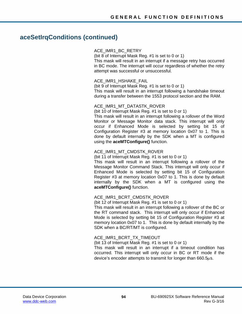
G E N E R A L F U N C T I O N D E F I N I T I O N S
Data Device Corporation BU-69092SX Software Reference Manual www.ddc-web.com Rev G-3/16
94
aceSetIrqConditions (continued) ACE_IMR1_BC_RETRY (bit 8 of Interrupt Mask Reg. #1 is set to 0 or 1) This mask will result in an interrupt if a message retry has occurred
in BC mode. The interrupt will occur regardless of whether the retry attempt was successful or unsuccessful.
ACE_IMR1_HSHAKE_FAIL (bit 9 of Interrupt Mask Reg. #1 is set to 0 or 1) This mask will result in an interrupt following a handshake timeout
during a transfer between the 1553 protocol section and the RAM. ACE_IMR1_MT_DATASTK_ROVER (bit 10 of Interrupt Mask Reg. #1 is set to 0 or 1) This mask will result in an interrupt following a rollover of the Word
Monitor or Message Monitor data stack. This interrupt will only occur if Enhanced Mode is selected by setting bit 15 of Configuration Register #3 at memory location 0x07 to 1. This is done by default internally by the SDK when a MT is configured using the aceMTConfigure() function.
ACE_IMR1_MT_CMDSTK_ROVER (bit 11 of Interrupt Mask Reg. #1 is set to 0 or 1) This mask will result in an interrupt following a rollover of the
Message Monitor Command Stack. This interrupt will only occur if Enhanced Mode is selected by setting bit 15 of Configuration Register #3 at memory location 0x07 to 1. This is done by default internally by the SDK when a MT is configured using the aceMTConfigure() function.
ACE_IMR1_BCRT_CMDSTK_ROVER (bit 12 of Interrupt Mask Reg. #1 is set to 0 or 1) This mask will result in an interrupt following a rollover of the BC or
the RT command stack. This interrupt will only occur if Enhanced Mode is selected by setting bit 15 of Configuration Register #3 at memory location 0x07 to 1. This is done by default internally by the SDK when a BC/RT/MT is configured.
ACE_IMR1_BCRT_TX_TIMEOUT (bit 13 of Interrupt Mask Reg. #1 is set to 0 or 1) This mask will result in an interrupt if a timeout condition has
occurred. This interrupt will only occur in BC or RT mode if the device’s encoder attempts to transmit for longer than 660.5µs.

G E N E R A L F U N C T I O N D E F I N I T I O N S
Data Device Corporation BU-69092SX Software Reference Manual www.ddc-web.com Rev G-3/16
95
aceSetIrqConditions (continued) ACE_IMR1_RAM_PAR_ERR (bit 14 of Interrupt Mask Reg. #1 is set to 0 or 1)
This mask will result in an interrupt if a RAM parity error occurs during a read access. This interrupt will only occur if Enhanced Mode is selected by setting bit 15 of Configuration Register #3 at memory location 0x07 to 1. This is done by default internally by the SDK when a BC/RT/MT is configured. The RAM Parity Enable option must also be set by setting bit 14 of Configuration Register #2 at memory location 0x02 to 1 for this interrupt to occur. This can be set by calling the aceSetRamParityChecking() function.
ACE_IMR2_BIT_TRIGGER (bit 0 of Interrupt Mask Reg. #2 is set to 0 or 1) This mask will result in an interrupt if a trigger condition is met. ACE_IMR2_BIT_COMPLETE (bit 1 of Interrupt Mask Reg. #2 is set to 0 or 1) This mask will result in an interrupt if protocol built-in self-test or the
RAM built-in self-test has been completed. Bit 0 of Interrupt Mask Reg. #2 at memory location 0x1D is not used.
ACE_IMR2_BC_UIRQ0 ACE_IMR2_BC_UIRQ1 ACE_IMR2_BC_UIRQ2 ACE_IMR2_BC_UIRQ3 (bits 2 - 5 of Interrupt Mask Reg. #2 are set to 0 or 1) This mask will result in an interrupt if the device is in Enhanced Bus
Controller Mode and an IRQ (Generate Interrupt) hardware instruction is generated by the device. The Interrupt Status Register at memory location 0x1E will contain the value of the lower 4 bits of the parameter associated with the IRQ instruction in bits 2 – 5.
ACE_IMR2_MT_DSTK_50P_ROVER (bit 6 of Interrupt Mask Reg. #2 is set to 0 or 1) For selective monitor mode, this mask will result in an interrupt if
the data stack is more than half full. This interrupt will occur at the end of the message in which the 50% rollover occurred.
ACE_IMR2_MT_CSTK_50P_ROVER (bit 7 of Interrupt Mask Reg. #2 is set to 0 or 1) For selective monitor mode, this mask will result in an interrupt if
the command stack is more than half full.

G E N E R A L F U N C T I O N D E F I N I T I O N S
Data Device Corporation BU-69092SX Software Reference Manual www.ddc-web.com Rev G-3/16
96
aceSetIrqConditions (continued) ACE_IMR2_RT_CIRC_50P_ROVER (bit 8 of Interrupt Mask Reg. #2 is set to 0 or 1) This mask will result in an interrupt if the circular buffer has rolled
over. For this interrupt to occur the device must have Enhanced Memory Management enabled by setting bit 1 of Configuration Register #2 at memory location 0x02 to 1. This is done by default internally by the SDK when an RT is configured using the aceRTConfigure() function. Another condition that must be set for this interrupt to occur is that the aceRTDataBlkMapToSA() function must be called with the ACE_RT_DBLK_CIRC_IRQ input parameter to set one of the Circular Buffer Interrupts (bit 3, 8, or 13) in the Subaddress Control Word to 1. Bit 3 is set to 1 for a Broadcast Circular Buffer Interrupt. Bit 8 is set to 1 for a Receive Circular Buffer Interrupt. Bit 13 is set to 1 for a Transmit Circular Buffer Interrupt.
ACE_IMR2_RT_CSTK_50P_ROVER (bit 9 of Interrupt Mask Reg. #2 is set to 0 or 1) For RT mode, this mask will result in an interrupt if the command
stack is more than half full. ACE_IMR2_BC_TRAP (bit 10 of Interrupt Mask Reg. #2 is set to 0 or 1) For BC mode, this mask will result in an interrupt if the BC has
fetched an illegal opcode or if the BC watchdog timer (frame timer) has timed out. An illegal opcode is one that is not defined, fails parity check, and/or has an incorrect value for one or more of bits 9 through 5.
ACE_IMR2_BC_CALLSTK_ERR (bit 11 of Interrupt Mask Reg. #2 is set to 0 or 1) For BC mode, this mask will result in an interrupt if there has been
a violation of the BC’s subroutine stack depth. This error occurs if either: (1) a call stack overflow condition or (2) a call stack underflow condition occurred.
ACE_IMR2_GPQ_ISQ_ROVER (bit 12 of Interrupt Mask Reg. #2 is set to 0 or 1) For BC mode, this mask will result in an interrupt if the General
Purpose Queue has rolled over. For RT mode, this mask will result in an interrupt if the interrupt status queue rolls over.
ACE_IMR2_RT_ILL_CMD (bit 13 of Interrupt Mask Reg. #2 is set to 0 or 1) For RT mode, this mask will result in an interrupt if an illegal
message has been received by the RT.

G E N E R A L F U N C T I O N D E F I N I T I O N S
Data Device Corporation BU-69092SX Software Reference Manual www.ddc-web.com Rev G-3/16
97
aceSetIrqConditions (continued) ACE_IMR2_BC_OPCODE_PARITY (bit 14 of Interrupt Mask Reg. #2 is set to 0 or 1) For BC mode, this mask will generate an interrupt if the opcode
word for a BC instruction fails its parity check. funcExternalISR (input parameter) This is the user designated ISR callback function written by the
user. This function will be called when the device generates an interrupt.
DESCRIPTION This function enables the selected interrupts as specified by the settings of interrupt mask registers 1 and 2 if bEnable is set to TRUE. If bEnable is set to FALSE then the selected interrupts are disabled by writing a 0 to the appropriate bit in interrupt mask registers 1 and 2. The selected interrupts may be logically OR’ed together in order to combine the operations into one statement and enable/disable multiple interrupt conditions.
RETURN VALUE ACE_ERR_SUCCESS The function completed successfully ACE_ERR_INVALID_DEVNUM An invalid device number was input to this function ACE_ERR_INVALID_STATE The device is not in a Ready state and the function
could not be completed ACE_WRN_RT_CFG_INVALID Operation of your device may be problematic
because one or more of the following interrupts have been enabled: Time Tag Rollover, RT Address Parity Error, and/or Ram Parity Error along with the Interrupt Status Queue. See Appendix B for details.

G E N E R A L F U N C T I O N D E F I N I T I O N S
Data Device Corporation BU-69092SX Software Reference Manual www.ddc-web.com Rev G-3/16
98
aceSetIrqConditions (continued)
EXAMPLE /*The following code would be used to enable only the End-Of-Message interrupt. */
S16BIT DevNum = 0; U16BIT bEnable = TRUE; S16BIT nResult = 0; nResult = aceSetIrqConditions(DevNum, bEnable, ACE_IMR1_EOM, funcExternalISR); if(nResult < 0) { printf(“Error in aceSetIrqConditions() function \n”); PrintOutError(nResult); return; } _________________________________________________________ //user defined callback function (funcExternalISR) sample void _DECL funcExternalISR(S16BIT DevNum, U32BIT Status) { //ISR implementation user defined callback routine printf(“An interrupt has occurred \n”); }
SEE ALSO aceSetIrqConfig()

G E N E R A L F U N C T I O N D E F I N I T I O N S
Data Device Corporation BU-69092SX Software Reference Manual www.ddc-web.com Rev G-3/16
99
aceSetIrqConfig This function sets the type of interrupt signal generated by the hardware.
PROTOTYPE #include “config.h” S16BIT _DECL aceSetIrqConfig(S16BIT DevNum, U16BIT wLvlOrPulse, U16BIT wAutoClear);
HARDWARE EMACE, E²MA
STATE Ready
MODE Advanced plus one of the following: BC, RT, MT, RTMT, MT-I, RTMT-I
PARAMETERS DevNum (input parameter) Logical Device Number Valid values: 0 – 31 wLvlOrPulse (input parameter) Define hardware interrupt operation Valid values: ACE_IRQ_LEVEL ACE_IRQ_PULSE wAutoClear (input parameter) Define register read and clear operation Valid Values: ACE_IRQ_AUTO_CLR ACE_IRQ_NO_AUTO_CLR
DESCRIPTION This function sets the type of interrupt signal generated by the hardware, and whether or not to auto clear status registers after they have been read. There is no need to call this function since it is automatically called when you set up your card as a BC, RT, or MT. The function is called with the wLvlOrPulse parameter set for ACE_IRQ_LEVEL, and the wAutoClear parameter set for ACE_IRQ_AUTO_CLR. If you would like to change the parameters you may do so by calling this function while you are in advanced mode of operation. The function cannot be used unless you are in advanced mode of operation. If you are using a card product from DDC you should never call this function.
G E N E R A L F U N C T I O N D E F I N I T I O N S
Data Device Corporation BU-69092SX Software Reference Manual www.ddc-web.com Rev G-3/16
100
aceSetIrqConfig (continued) RETURN VALUE
ACE_ERR_SUCCESS The function completed successfully ACE_ERR_INVALID_DEVNUM An invalid device number was input to this function ACE_ERR_INVALID_STATE The device is not in a Ready state and the function
could not be completed ACE_ERR_NOT_SUPPORTED This function is only supported in Advanced mode
of operation
EXAMPLE /* If it is desirable to have the 1553 hardware to not clear the interrupt registers once they have been read and the 1553 hardware is configured in the system for a level interrupt, then the following example would be used. */
S16BIT DevNum = 0; nResult = aceSetIrqConfig (DevNum, ACE_IRQ_LEVEL, ACE_IRQ_NO_AUTO_CLR); if(nResult < 0) { printf(“Error in aceSetIrqConfig() function \n”); PrintOutError(nResult); return; }
SEE ALSO aceSetIrqConditions()

G E N E R A L F U N C T I O N D E F I N I T I O N S
Data Device Corporation BU-69092SX Software Reference Manual www.ddc-web.com Rev G-3/16
101
aceSetMetrics This function allows the user to enable built-in performance metrics for informative purposes.
PROTOTYPE #include “Config.h” S16BIT _DECL aceSetMetrics (S16BIT DevNum, U16BIT bEnable);
HARDWARE EMACE, E²MA, AceXtreme
STATE Ready
MODE BC, RT, RTMT, MT, MT-I, RTMT-I
PARAMETERS DevNum (input parameter) Logical Device Number Valid values: 0 – 31 bEnable (input parameter) Enable/Disable System Metrics Valid values: FALSE (0) Disable system metrics TRUE (1) Enable system metrics
DESCRIPTION This function allows the user to enable built-in performance metrics for informative purposes. Built-in test metrics can report the number of messages in the host buffer, the total number of messages lost since the host buffer was installed, the current percentage of the host buffer that is used, the highest percentage of the host buffer used since it was installed, the total number of messages lost on the device’s hardware stack, the current percentage of the stack that is used, and the highest percentage of the stack used. In addition, while in BC mode, built-in test metrics can report the number of messages lost on the GPQ, the current percentage of the GPQ that is used, and the highest percentage of the GPQ that is used.

G E N E R A L F U N C T I O N D E F I N I T I O N S
Data Device Corporation BU-69092SX Software Reference Manual www.ddc-web.com Rev G-3/16
102
aceSetMetrics (continued) RETURN VALUE
ACE_ERR_SUCCESS The function completed successfully ACE_ERR_INVALID_DEVNUM An invalid device number was input to this function ACE_ERR_INVALID_STATE The device is not in a Ready state ACE_ERR_INVALID_MODE The device is not in BC, RT, MT, or RTMT mode
EXAMPLE S16BIT DevNum = 0; U16BIT bEnable = 1; S16BIT nResult = 0; nResult = aceSetMetrics(DevNum, bEnable); if(nResult < 0) { printf(“Error in aceSetMetrics() function \n”); PrintOutError(nResult); return; }
SEE ALSO aceMTGetHBufMetric() aceMTGetStkMetric() aceRTGetHBufMetric() aceRTGetStkMetric() aceBCGetHBufMetric() aceBCGetGPQMetric()

G E N E R A L F U N C T I O N D E F I N I T I O N S
Data Device Corporation BU-69092SX Software Reference Manual www.ddc-web.com Rev G-3/16
103
aceSetRamParityChecking This function will be used to enable or disable RAM parity checking.
PROTOTYPE #include “config.h” S16BIT _DECL aceSetRamParityChecking(S16BIT DevNum, U16BIT wRamParityEnable);
HARDWARE EMACE, E²MA, AceXtreme
STATE Ready
MODE Not Applicable
PARAMETERS DevNum (input parameter) Logical Device Number Valid values: 0 – 31 wRamParityEnable (input parameter) This parameter specifies the desired RAM checking operation Valid values: ACE_ENABLE_PARITY_CHECK (bit 14 of Configuration Reg. #2 is set to 1) ACE_DISABLE_PARITY_CHECK (bit 14 of Configuration Reg. #2 is set to 0)
DESCRIPTION This function will be used to enable or disable RAM parity checking. If the hardware design includes 17-bit RAM, this option can be used to employ the automatic RAM parity checking. If the RAM is 16-bit, this option has no effect. The function will set bit 14 of Configuration Register #2 to a 0 or a 1 to respectively disable or enable the RAM parity checking. The RAM parity checking is disabled by default internally in the SDK when a BC, RT, or MT is configured and can be enabled with a call to this function after the BC, RT or MT has been configured.

G E N E R A L F U N C T I O N D E F I N I T I O N S
Data Device Corporation BU-69092SX Software Reference Manual www.ddc-web.com Rev G-3/16
104
aceSetRamParityChecking (continued) RETURN VALUE
ACE_ERR_SUCCESS The function completed successfully ACE_ERR_INVALID_DEVNUM An invalid device number was input to this function ACE_ERR_INVALID_STATE The device is not in a Ready state and the function could
not be completed
EXAMPLE /* The following code can be used for hardware that incorporates 17-bit RAM. */
S16BIT DevNum = 0; nResult = aceSetRamParityChecking(DevNum, ACE_ENABLE_PARITY_CHECK) if(nResult < 0) { printf(“Error in aceSetRamParityChecking() function \n”); PrintOutError(nResult); return; }
SEE ALSO None

G E N E R A L F U N C T I O N D E F I N I T I O N S
Data Device Corporation BU-69092SX Software Reference Manual www.ddc-web.com Rev G-3/16
105
aceSetRespTimeOut This function sets the message RT response timeout timer on the hardware.
PROTOTYPE #include “config.h” S16BIT _DECL aceSetRespTimeOut(S16BIT DevNum, U16BIT wRespTimeOut);
HARDWARE EMACE, E²MA, AceXtreme
STATE Ready
MODE Not Applicable
PARAMETERS DevNum (input parameter) Logical Device Number Valid values: 0 – 31 WrespTimeOut (input parameter) Message RT Response Timeout Valid values: ACE_RESPTIME_18US - 18.5 µs timeout (default) ACE_RESPTIME_22US - 22.5 µs timeout ACE_RESPTIME_50US - 50.5 µs timeout ACE_RESPTIME_130US - 130 µs timeout
DESCRIPTION This function sets the device’s response timeout timer on the hardware by configuring bits 9 and 10 of Configuration Register # 5 at location 0x09. This timer is used in BC mode, in RT mode (for messages in which the device is the receiving RT in an RT-RT transfer), and in the message MT mode. If an RT is fairly slow to respond to messages from a Bus Controller, as might be the case for a very long bus length between the two terminals, it might be necessary to increase the timeout to 50.5 µs. This will cause the BC to wait a little longer for a response before declaring an error and continuing with the next message.

G E N E R A L F U N C T I O N D E F I N I T I O N S
Data Device Corporation BU-69092SX Software Reference Manual www.ddc-web.com Rev G-3/16
106
aceSetRespTimeOut (continued) RETURN VALUE
ACE_ERR_SUCCESS This function has successfully set the response timeout value
ACE_ERR_INVALID_DEVNUM An invalid device number was input to this function ACE_ERR_INVALID_STATE The device is not in a Ready state and the function could
not complete ACE_ERR_RESPTIME The wRespTimeOut input parameter contains an incorrect
value
EXAMPLE //sets the response timeout value S16BIT DevNum = 0; S16BIT nResult = 0; nResult = aceSetRespTimeOut (DevNum, ACE_RESPTIME_50US); if(nResult < 0) { printf(“Error in aceSetRespTimeOut() function \n”); PrintOutError(nResult); return; }
SEE ALSO None

G E N E R A L F U N C T I O N D E F I N I T I O N S
Data Device Corporation BU-69092SX Software Reference Manual www.ddc-web.com Rev G-3/16
107
aceSetTimeTagRes This function sets the time tag resolution of the device.
PROTOTYPE #include “config.h” S16BIT _DECL aceSetTimeTagRes(S16BIT DevNum, U16BIT wTTRes);
HARDWARE EMACE, E²MA, AceXtreme
STATE Ready
MODE Not Applicable
PARAMETERS DevNum (input parameter) Logical Device Number Valid values: 0 – 31 wTTRes (input parameter) Time Tag Resolution Valid values: ACE_TT_64US – 64 µs resolution ACE_TT_32US – 32 µs resolution ACE_TT_16US – 16 µs resolution ACE_TT_8US - 8 µs resolution ACE_TT_4US - 4 µs resolution ACE_TT_2US - 2 µs resolution ACE_TT_1US - 1 µs resolution (E²MA only) ACE_TT_TEST - Increment manually ACE_TT_EXT – Use External Clock
DESCRIPTION This function sets the resolution of the Time Tag Register by setting bits 7 - 9 of Configuration Register #2 at memory offset 0x02. The Time Tag Resolution is initially set to a resolution of 2µs when the aceInitialize() function is first called. The user can then use this function to change the time tag resolution to any of the valid values mentioned above.

G E N E R A L F U N C T I O N D E F I N I T I O N S
Data Device Corporation BU-69092SX Software Reference Manual www.ddc-web.com Rev G-3/16
108
aceSetTimeTagRes (continued) RETURN VALUE
ACE_ERR_SUCCESS The function completed successfully ACE_ERR_INVALID_DEVNUM An invalid device number has been input to this function ACE_ERR_INVALID_STATE The device is not in the Ready state and the function could
not be completed ACE_ERR_TIMETAG_RES The wTTRes input by the user does not contain a valid
value
EXAMPLE //To set the time tag resolution to 16 µs. S16BIT DevNum = 0; S16BIT nResult = 0; nResult = aceSetTimeTagRes (DevNum, ACE_TT_16_US); if(nResult < 0) {
printf(“Error in aceSetTimeTagRes() function \n”); PrintOutError(nResult);
return; }
SEE ALSO None
G E N E R A L F U N C T I O N D E F I N I T I O N S
Data Device Corporation BU-69092SX Software Reference Manual www.ddc-web.com Rev G-3/16
109
aceSetTimeTagValue This function allows the user to modify the value of the time tag register.
PROTOTYPE #include “config.h” S16BIT _DECL aceSetTimeTagValue(S16BIT DevNum, U16BIT wTTValue);
HARDWARE EMACE, E²MA, AceXtreme
STATE Reset, Ready, Run
MODE Not Applicable
PARAMETERS DevNum (input parameter) Logical Device Number Valid values: 0 – 31 wTTValue (input parameter) Time Tag Value Valid values: 0x0000 – 0xFFFF
DESCRIPTION This function sets the value of the Time Tag Register.
RETURN VALUE ACE_ERR_SUCCESS The function completed successfully ACE_ERR_INVALID_DEVNUM The device specified is invalid
G E N E R A L F U N C T I O N D E F I N I T I O N S
Data Device Corporation BU-69092SX Software Reference Manual www.ddc-web.com Rev G-3/16
110
aceSetTimeTagValue (continued) EXAMPLE
//To set the time tag value. S16BIT DevNum = 0; S16BIT nResult = 0; nResult = aceSetTimeTagValue (DevNum, 0x0023); if(nResult < 0) {
printf(“Error in aceSetTimeTagValue() function \n”); PrintOutError(nResult);
return; }
SEE ALSO None

G E N E R A L F U N C T I O N D E F I N I T I O N S
Data Device Corporation BU-69092SX Software Reference Manual www.ddc-web.com Rev G-3/16
111
aceSetTimeTagValueEx This function sets the value of the card’s 48-bit time tag register.
PROTOTYPE #include “config.h” S16BIT _DECL aceGetTimeTagValueEx(S16BIT DevNum, U64BIT ullTTValue);
HARDWARE AceXtreme
STATE Ready, Run
MODE MT-I
PARAMETERS DevNum (input parameter) Logical Device Number Valid values: 0 – 31 UllTTValue (input parameter) Value to write to the 48-bit time tag register.
DESCRIPTION This function sets the value of the 48-bit Time Tag Register in any state.
RETURN VALUE ACE_ERR_INVALID_DEVNUM An invalid device number was input ACE_ERR_SUCCESS The function completed successfully

G E N E R A L F U N C T I O N D E F I N I T I O N S
Data Device Corporation BU-69092SX Software Reference Manual www.ddc-web.com Rev G-3/16
112
aceSetTimeTagValueEx (continued) EXAMPLE
//To set the time tag value. S16BIT DevNum = 0; S16BIT nResult = 0; nResult = aceSetTimeTagValueEx (DevNum, 0xDCBA87654321); if(nResult < 0) {
printf(“Error in aceSetTimeTagValueEx() function \n”); PrintOutError(nResult);
return; }
SEE ALSO aceGetTimeTagValueEx()

G E N E R A L F U N C T I O N D E F I N I T I O N S
Data Device Corporation BU-69092SX Software Reference Manual www.ddc-web.com Rev G-3/16
113
aceTestCanEbrLoop This function performs an EBR to CANbus loopback test.
PROTOTYPE #include “test.h” S16BIT _DECL aceTestCanEbrLoop(S16BIT DevNum, TESTRESULT *pTest);
HARDWARE EMACE, E²MA, AceXtreme
STATE Ready
MODE Test
PARAMETERS DevNum (input parameter) Logical Device Number Valid values: 0 – 31 pTest (output parameter) Pointer to a TESTRESULT structure that will contain the results of the interrupt tests
DESCRIPTION This function performs an EBR to CANbus loopback test. An external loopback cable is required.
RETURN VALUE ACE_ERR_SUCCESS The function completed successfully ACE_ERR_INVALID_DEVNUM An invalid device number was input to this function ACE_ERR_INVALID_STATE The device is not in a Ready state ACE_ERR_INVALID_CARD The device is not in ACE_ACCESS_CARD mode set by
the aceInitialize() function ACE_ERR_NOT_SUPPORTED The function does not support the given device
G E N E R A L F U N C T I O N D E F I N I T I O N S
Data Device Corporation BU-69092SX Software Reference Manual www.ddc-web.com Rev G-3/16
114
aceTestCanEbrLoop (continued) EXAMPLE
S16BIT DevNum = 0; S16BIT nResult = 0; TESTRESULT *pTest; aceInitialize(DevNum,ACE_ACCESS_CARD,ACE_MODE_TEST,0,0,0); nResult = aceTestCanEbrLoop(DevNum, pTest); if(nResult < 0) { printf(“Error in aceTestCanEbrLoop() function \n”); PrintOutError(nResult); return; }
SEE ALSO aceTestRegisters() aceTestMemory() aceTestProtocol() aceTestVectors() aceTestLoopBack()
G E N E R A L F U N C T I O N D E F I N I T I O N S
Data Device Corporation BU-69092SX Software Reference Manual www.ddc-web.com Rev G-3/16
115
aceTestIrqs This function will verify that interrupts are working.
PROTOTYPE #include “test.h” S16BIT _DECL aceTestIrqs(S16BIT DevNum, TESTRESULT *pTest);
HARDWARE EMACE, E²MA, AceXtreme
STATE Ready
MODE Test
PARAMETERS DevNum (input parameter) Logical Device Number Valid values: 0 – 31 pTest (output parameter) Pointer to a TESTRESULT structure that will contain the results of the interrupt tests
DESCRIPTION This function will reset the device, and set bits 7 – 9 of Configuration Register #2 to a value of 011, which sets the time tag resolution to Test Mode. The interrupt is selected to be a level type interrupt by setting bit 3 of Configuration Register #2 to a 1, unless you are using a PC/104 card with DOS or VxWorks. The time tag rollover is enabled by setting bit 6 in Interrupt Mask Register #1. This function then generates an interrupt by loading the time tag register with a value of 0xFFFF and then incrementing it to generate a time tag rollover interrupt. The function then checks that it was captured by the internal interrupt handler.
RETURN VALUE ACE_ERR_SUCCESS The function completed successfully ACE_ERR_INVALID_DEVNUM An invalid device number was input to this function ACE_ERR_INVALID_STATE The device is not in a Ready state ACE_ERR_INVALID_MODE The device is not in Test mode ACE_ERR_TEST_BADSTRUCT The pTest pointer to a TESTRESULT structure
input by the user is Null ACE_ERR_INVALID_ACCESS The device is not a card because it is not in
ACE_ACCESS_CARD mode set by the aceInitialize() function

G E N E R A L F U N C T I O N D E F I N I T I O N S
Data Device Corporation BU-69092SX Software Reference Manual www.ddc-web.com Rev G-3/16
116
aceTestIrqs (continued) EXAMPLE
S16BIT DevNum = 0; S16BIT nResult = 0; TESTRESULT *pTest; aceInitialize(DevNum,ACE_ACCESS_CARD,ACE_MODE_TEST,0,0,0); nResult = aceTestIrqs(DevNum, pTest); if(nResult < 0) { printf(“Error in aceTestIrqs() function \n”); PrintOutError(nResult); return; }
SEE ALSO aceTestRegisters() aceTestMemory() aceTestProtocol() aceTestVectors() aceTestLoopBack()

G E N E R A L F U N C T I O N D E F I N I T I O N S
Data Device Corporation BU-69092SX Software Reference Manual www.ddc-web.com Rev G-3/16
117
aceTestLoopBack This function performs the loopback function test.
PROTOTYPE #include “test.h” U32BIT _DECL aceTestLoopBack(S16BIT DevNum, TESTRESULT *pTest));
HARDWARE EMACE, E²MA, AceXtreme
STATE Ready
MODE Test
PARAMETERS DevNum (input parameter) Logical Device Number Valid values: 0 – 31 dwMemAddr Address of the memory location to read pTest (output parameter) Pointer to a TESTRESULT structure that will contain the results of the lookback test
DESCRIPTION This function will perform a Bus A to Bus B loop around self test on the EMACE, E²MA, or AceXtreme device. Bus A must be connected to Bus B with the proper termination and coupling for the test to pass.
RETURN VALUE ACE_ERR_SUCCESS The function completed successfully ACE_ERR_INVALID_DEVNUM An invalid device number entered ACE_ERR_INVALID_STATE The device is not in a Ready state ACE_ERR_INVALID_ACCESS The device is not a card because it is not in
ACE_ACCESS_CARD mode set by the aceInitialize() function
ACE_ERR_INVALID_MODE The device is not in Test mode ACE_ERR_TEST_BADSTRUCT The pTest pointer to a TESTRESULT structure
input by the user is Null

G E N E R A L F U N C T I O N D E F I N I T I O N S
Data Device Corporation BU-69092SX Software Reference Manual www.ddc-web.com Rev G-3/16
118
aceTestLookBack (continued) EXAMPLE
S16BIT DevNum = 0; TESTRESULT sTest; S16BIT nResult = 0; nResult = aceTestLoopBack (DevNum, &sTest); if(nResult < 0) { printf(“Error in aceTestLoopBack() function \n”); PrintOutError(nResult); return; } if(sTest.wResult == ACE_TEST_PASSED) { printf("Loopback Test Passed.\n"); } else { printf("Loopback Test Failed, %d fails,
expected data = %04x, actual data = %04x\n", sTest.wCount, sTest.wExpData,sTest.wActData);
}
SEE ALSO aceTestIrqs() aceTestRegisters() aceTestMemory() aceTestProtocol() aceTestVectors()

G E N E R A L F U N C T I O N D E F I N I T I O N S
Data Device Corporation BU-69092SX Software Reference Manual www.ddc-web.com Rev G-3/16
119
aceTestMemory This function tests the hardware’s memory.
PROTOTYPE #include “test.h” S16BIT _DECL aceTestMemory(S16BIT DevNum, TESTRESULT *pTest, U16BIT wValue);
HARDWARE EMACE, E²MA, AceXtreme
STATE Ready
MODE Test
PARAMETERS DevNum (input parameter) Logical Device Number Valid values: 0 – 31 pTest (output parameter) Pointer to a TESTRESULT structure that will contain the results of the memory tests wValue (input parameter) Test value to be written and read during memory tests
DESCRIPTION This function tests hardware memory. It fills all of the memory with wValue and verifies by reading each location back and comparing to make sure the values are the same.
RETURN VALUE ACE_ERR_SUCCESS The function successfully completed and wrote any
memory errors to the TESTRESULT structure ACE_ERR_INVALID_DEVNUM An invalid device number was input to this function ACE_ERR_INVALID_STATE The device is not in a Ready state ACE_ERR_INVALID_MODE The device is not in Test mode ACE_ERR_TEST_BADSTRUCT The pTest pointer to the TESTRESULT structure
input by the user is Null
G E N E R A L F U N C T I O N D E F I N I T I O N S
Data Device Corporation BU-69092SX Software Reference Manual www.ddc-web.com Rev G-3/16
120
aceTestMemory (continued) EXAMPLE
S16BIT DevNum = 0; S16BIT nResult = 0; TESTRESULT *pTest; U16BIT wValue = 0xA5A5; aceInitialize(DevNum,ACE_ACCESS_CARD,ACE_MODE_TEST,0,0,0); nResult = aceTestMemory(DevNum, pTest, wValue); if(nResult < 0) { printf(“Error in aceTestMemory() function \n”); PrintOutError(nResult); return; }
SEE ALSO aceTestRegisters() aceTestProtocol() aceTestIrqs() aceTestVectors() aceTestLoopBack()

G E N E R A L F U N C T I O N D E F I N I T I O N S
Data Device Corporation BU-69092SX Software Reference Manual www.ddc-web.com Rev G-3/16
121
aceTestProtocol This function performs a test on the hardware protocol functions.
PROTOTYPE #include “test.h” aceTestProtocol(S16BIT DevNum, TESTRESULT *pTest);
HARDWARE EMACE, E²MA, AceXtreme
STATE Ready
MODE Test
PARAMETERS DevNum (input parameter) Logical Device Number Valid values: 0 – 31 pTest (output parameter) Pointer to a TESTRESULT structure that will contain the results of the protocol tests
DESCRIPTION The function will reset the device, and set bits 8 – 11 in Configuration Register #1 to a value of 1 to configure the device. The function will then set the time tag resolution to 2 µs by setting bits 7 – 9 of Configuration Register # 2 to a value of 101. This function then performs a series of tests on the hardware protocol functions to make sure that the device is working properly.
RETURN VALUE ACE_ERR_SUCCESS The function completed successfully ACE_ERR_INVALID_DEVNUM An invalid device number was passed to this function ACE_ERR_INVALID_STATE The device is not in a Ready state ACE_ERR_INVALID_MODE The device is not in Test mode ACE_ERR_TEST_BADSTRUCT The pTest pointer to the TESTRESULT structure
input by the user is Null

G E N E R A L F U N C T I O N D E F I N I T I O N S
Data Device Corporation BU-69092SX Software Reference Manual www.ddc-web.com Rev G-3/16
122
aceTestProtocol (continued) EXAMPLE
S16BIT DevNum = 0; TESTRESULT *pTest; aceInitialize(DevNum,ACE_ACCESS_CARD,ACE_MODE_TEST,0,0,0); nResult = aceTestProtocol(DevNum, pTest); if(nResult < 0) { printf(“Error in aceTestProtocol() function \n”); PrintOutError(nResult); return; }
SEE ALSO aceTestRegisters() aceTestMemory() aceTestIrqs() aceTestVectors() aceTestLoopBack()

G E N E R A L F U N C T I O N D E F I N I T I O N S
Data Device Corporation BU-69092SX Software Reference Manual www.ddc-web.com Rev G-3/16
123
aceTestRegisters This function tests hardware registers.
PROTOTYPE #include “test.h” S16BIT _DECL aceTestRegisters(S16BIT DevNum, TESTRESULT *pTest);
HARDWARE EMACE, E²MA, AceXtreme
STATE Ready
MODE Test
PARAMETERS DevNum (input parameter) Logical Device Number Valid values: 0 – 31 pTest (output parameter) Pointer to a TESTRESULT structure that will return the results of the register tests.
DESCRIPTION This function tests hardware registers by performing a series of reads and writes to the hardware registers.
RETURN VALUE ACE_ERR_SUCCESS The function completed successfully ACE_ERR_INVALID_DEVNUM An invalid device number was input to this function ACE_ERR_INVALID_STATE The device is not in a Ready state ACE_ERR_INVALID_MODE The device is not in Test mode ACE_ERR_TEST_BADSTRUCT An invalid pointer to a TESTRESULT structure was
input to this function

G E N E R A L F U N C T I O N D E F I N I T I O N S
Data Device Corporation BU-69092SX Software Reference Manual www.ddc-web.com Rev G-3/16
124
aceTestRegisters (continued) EXAMPLE
S16BIT DevNum = 0; TESTRESULT *pTest; aceInitialize(DevNum,ACE_ACCESS_CARD,ACE_MODE_TEST,0,0,0); nResult = aceTestRegisters(DevNum, pTest); if(nResult < 0) { printf(“Error in aceTestRegisters() function \n”); PrintOutError(nResult); return; }
SEE ALSO aceTestMemory() aceTestProtocol() aceTestIrqs() aceTestVectors() aceTestLoopBack()

G E N E R A L F U N C T I O N D E F I N I T I O N S
Data Device Corporation BU-69092SX Software Reference Manual www.ddc-web.com Rev G-3/16
125
aceTestVectors This function will test the hardware using a vector file.
PROTOTYPE #include “test.h” S16BIT _DECL aceTestVectors(S16BIT DevNum, TESTRESULT *pTest, char *pFileName);
HARDWARE EMACE, E²MA, AceXtreme
STATE Ready
MODE Test
PARAMETERS DevNum (input parameter) Logical Device Number Valid values: 0 – 31 pTest (output parameter) Pointer to a TESTRESULT structure that will contain the results of the register tests pFileName (input parameter) A pointer to the Test Vector source file
DESCRIPTION This function tests hardware using a vector file. Test vectors will be retrieved from the source file one at a time and applied to the 1553 hardware. After applying a complete group of vectors, registers and memory will be read to ensure the test group passed.
RETURN VALUE ACE_ERR_SUCCESS The function has completed successfully ACE_ERR_INVALID_DEVNUM An invalid device number was input to this function ACE_ERR_INVALID_STATE The device is not in a ready state ACE_ERR_INVALID_MODE The device is not in a test mode ACE_ERR_TEST_BADSTRUCT The pTest pointer to a TESTRESULT structure
input by the user is Null ACE_ERR_TEST_FILE The pFileName pointer to the Test Vector Source
file is Null
G E N E R A L F U N C T I O N D E F I N I T I O N S
Data Device Corporation BU-69092SX Software Reference Manual www.ddc-web.com Rev G-3/16
126
aceTestVectors (continued) EXAMPLE
S16BIT DevNum = 0; S16BIT nResult = 0; TESTRESULT *pTest; char *pFileName = “c:\\acetest.vec”; aceInitialize(DevNum,ACE_ACCESS_CARD,ACE_MODE_TEST,0,0,0); nResult = aceTestVectors(DevNum, pTest, pFileName); if(nResult < 0) { printf(“Error in aceTestVectors() function \n”); PrintOutError(nResult); return; }
SEE ALSO aceTestRegisters() aceTestMemory() aceTestIrqs() aceTestProtocol() aceTestLoopBack()

G E N E R A L F U N C T I O N D E F I N I T I O N S
Data Device Corporation BU-69092SX Software Reference Manual www.ddc-web.com Rev G-3/16
127
aceTestVectorsStatic This function tests hardware using a constant vector array.
PROTOTYPE #include “test.h” S16BIT _DECL aceTestVectorsStatic(S16BIT DevNum, TESTRESULT *pTest);
HARDWARE EMACE
STATE Ready
MODE Test
PARAMETERS DevNum (input parameter) Logical Device Number Valid values: 0 – 31 pTest (output parameter) Pointer to a TESTRESULT structure that will contain the results of the register tests
DESCRIPTION This function tests hardware using a constant vector array.
RETURN VALUE ACE_ERR_SUCCESS The function has completed successfully ACE_ERR_INVALID_DEVNUM An invalid device number was input to this function ACE_ERR_INVALID_STATE The device is not in a ready state ACE_ERR_INVALID_MODE The device is not in a test mode ACE_ERR_INVALID_ACCESS The device is not in ACE_ACCESS_CARD mode set by the aceInitialize() function ACE_ERR_TEST_BADSTRUCT The pTest pointer to a TESTRESULT structure
input by the user is Null ACE_ERR_NOT_SUPPORTED The function does not currently support this device

G E N E R A L F U N C T I O N D E F I N I T I O N S
Data Device Corporation BU-69092SX Software Reference Manual www.ddc-web.com Rev G-3/16
128
aceTestVectorsStatic (continued) EXAMPLE
S16BIT DevNum = 0; S16BIT nResult = 0; TESTRESULT *pTest; aceInitialize(DevNum,ACE_ACCESS_CARD,ACE_MODE_TEST,0,0,0); nResult = aceTestVectorsStatic(DevNum, pTest); if(nResult < 0) { printf(“Error in aceTestVectorsStatic() function \n”); PrintOutError(nResult); return; }
SEE ALSO aceTestRegisters() aceTestMemory() aceTestIrqs() aceTestProtocol() aceTestLoopBack()

G E N E R A L F U N C T I O N D E F I N I T I O N S
Data Device Corporation BU-69092SX Software Reference Manual www.ddc-web.com Rev G-3/16
129
acexClrDiscConfigure This function clears all discrete configurations.
PROTOTYPE #include “dio.h” S16BIT _DECL acexClrDiscConfigure(S16BIT DevNum);
HARDWARE Multi-Function AceXtreme
STATE Ready
MODE BC, MRT, MT-I
PARAMETERS DevNum (input parameter) Logical Device Number Valid values: 0 – 31
DESCRIPTION This function is used to clear all discrete configurations information at the same time.
RETURN VALUE ACE_ERR_SUCCESS The function completed successfully ACE_ERR_INVALID_DEVNUM An invalid device number was input to this function ACE_ERR_INVALID_STATE The device is not a Ready or Run State ACE_ERR_INVALID_CARD The device does not support this function ACE_ERR_NOT_SUPPORTED The device does not support triggers
EXAMPLE S16BIT DevNum = 0; S16BIT nResult = 0;
nResult = acexClrDiscConfig(DevNum); if(nResult < 0) { printf(“Error in acexClrDiscConfig() function \n”); PrintOutError(nResult); return; }
SEE ALSO acexSetDiscConfigure()

G E N E R A L F U N C T I O N D E F I N I T I O N S
Data Device Corporation BU-69092SX Software Reference Manual www.ddc-web.com Rev G-3/16
130
acexEITxShutdownDisable Disables the Error Injection transmitter to shutdown after 668 µseconds.
PROTOTYPE #include “config.h” S16BIT _DECL acexEITxShutdownDisable(S16BIT DevNum);
HARDWARE Multi-Function AceXtreme
STATE Ready
MODE BC, MRT
PARAMETERS DevNum (input parameter) Logical Device Number Valid values: 0 – 31
DESCRIPTION This function disables the Error Injection transmitter to shutdown after 668 µseconds.
RETURN VALUE ACE_ERR_SUCCESS The function has completed successfully ACE_ERR_INVALID_DEVNUM An invalid device number was input to this function ACE_ERR_INVALID_STATE The device is not in a ready state ACE_ERR_NOT_SUPPORTED The function does not currently support this device
EXAMPLE S16BIT DevNum = 0; S16BIT nResult = 0; nResult = acexEITxShutdownDisable (DevNum); if(nResult < 0) { printf(“Error in acexEITxShutdownDisable() function \n”); PrintOutError(nResult); return; }
SEE ALSO acexEITxShutdownEnable()

G E N E R A L F U N C T I O N D E F I N I T I O N S
Data Device Corporation BU-69092SX Software Reference Manual www.ddc-web.com Rev G-3/16
131
acexEITxShutdownEnable Enables the Error Injection transmitter to shutdown after 668 µseconds.
PROTOTYPE #include “config.h” S16BIT _DECL acexEITxShutdownEnable(S16BIT DevNum);
HARDWARE Multi-Function AceXtreme
STATE Ready
MODE BC, MRT
PARAMETERS DevNum (input parameter) Logical Device Number Valid values: 0 – 31
DESCRIPTION This function enables the Error Injection transmitter to shutdown after 668 µseconds.
RETURN VALUE ACE_ERR_SUCCESS The function has completed successfully ACE_ERR_INVALID_DEVNUM An invalid device number was input to this function ACE_ERR_INVALID_STATE The device is not in a ready state ACE_ERR_NOT_SUPPORTED The function does not currently support this device
EXAMPLE S16BIT DevNum = 0; S16BIT nResult = 0; nResult = acexEITxShutdownEnable (DevNum); if(nResult < 0) { printf(“Error in acexEITxShutdownEnable() function \n”); PrintOutError(nResult); return; }
SEE ALSO acexEITxShutdownDisable()

G E N E R A L F U N C T I O N D E F I N I T I O N S
Data Device Corporation BU-69092SX Software Reference Manual www.ddc-web.com Rev G-3/16
132
acexGetAmplitude This function gets the amplitude of the transceiver for a particular channel.
PROTOTYPE #include “config.h” S16BIT _DECL acexGetAmplitude(S16BIT DevNum, U32BIT *pu32Amplitude);
HARDWARE AceXtreme
STATE Ready
MODE None
PARAMETERS DevNum (input parameter) Logical Device Number Valid values: 0 – 31 pu32Amplitude (output parameter) Pointer to storage for transmit amplitude (!= NULL). 0x0000 – 0x03FF
(See Device Hardware Manual or Datasheet for output voltage specification)
DESCRIPTION This function gets the amplitude of the transceiver for a particular channel.
RETURN VALUE ACE_ERR_SUCCESS The function has completed successfully ACE_ERR_INVALID_DEVNUM An invalid device number was input to this function ACE_ERR_INVALID_STATE The device is not in a ready state ACE_ERR_NOT_SUPPORTED The function does not currently support this device

G E N E R A L F U N C T I O N D E F I N I T I O N S
Data Device Corporation BU-69092SX Software Reference Manual www.ddc-web.com Rev G-3/16
133
acexGetAmplitude (continued) EXAMPLE
S16BIT DevNum = 0; S16BIT nResult = 0; U32BIT u32Amplitude; nResult = acexGetAmplitude(DevNum, &u32Amplitude); if(nResult < 0) { printf(“Error in acexGetAmplitude() function \n”); PrintOutError(nResult); return; }
SEE ALSO acexSetAmplitude()

G E N E R A L F U N C T I O N D E F I N I T I O N S
Data Device Corporation BU-69092SX Software Reference Manual www.ddc-web.com Rev G-3/16
134
acexGetCoupling This function gets the Bus Coupling and Termination.
PROTOTYPE #include “config.h” S16BIT _DECL acexGetCoupling(S16BIT DevNum, CHANNEL_COUPLING *eCoupling, CHANNEL_TERMINATION *eTermination);
HARDWARE AceXtreme
STATE Ready
MODE None
PARAMETERS DevNum (input parameter) Logical Device Number Valid values: 0 – 31 eCoupling (output parameter) Pointer Pointer to storage for bus coupling (!= NULL). ACE_COUPLING_TRANSFORMER ACE_COUPLING_DIRECT eTermination (output parameter) Pointer Pointer to storage for bus coupling (!= NULL). ACE_TERMINATION_NONE ACE_TERMINATION_HALF ACE_TERMINATION_FULL
DESCRIPTION This function gets the Bus Coupling and Termination.
RETURN VALUE ACE_ERR_SUCCESS The function has completed successfully ACE_ERR_INVALID_DEVNUM An invalid device number was input to this function ACE_ERR_INVALID_STATE The device is not in a ready state ACE_ERR_NOT_SUPPORTED The function does not currently support this device

G E N E R A L F U N C T I O N D E F I N I T I O N S
Data Device Corporation BU-69092SX Software Reference Manual www.ddc-web.com Rev G-3/16
135
acexGetCoupling (continued) EXAMPLE
S16BIT DevNum = 0; S16BIT nResult = 0; CHANNEL_COUPLING eCoupling; CHANNEL_TERMINATION eTermination; nResult = acexGetCoupling(DevNum, &eCoupling, &eTermination); if(nResult < 0) { printf(“Error in acexGetCoupling() function \n”); PrintOutError(nResult); return; }
SEE ALSO acexSetCoupling()

G E N E R A L F U N C T I O N D E F I N I T I O N S
Data Device Corporation BU-69092SX Software Reference Manual www.ddc-web.com Rev G-3/16
136
acexSetAmplitude This function sets the amplitude of the transceiver for a particular channel.
PROTOTYPE #include “config.h” S16BIT _DECL acexSetAmplitude(S16BIT DevNum, U32BIT u32Amplitude);
HARDWARE AceXtreme
STATE Ready
MODE None
PARAMETERS DevNum (input parameter) Logical Device Number Valid values: 0 – 31
u32Amplitude (input parameter) 0x0000 – 0x03FF (See Device Hardware Manual or Datasheet for output voltage specification)
DESCRIPTION This function sets the amplitude of the transceiver for a particular channel.
RETURN VALUE ACE_ERR_SUCCESS The function has completed successfully ACE_ERR_INVALID_DEVNUM An invalid device number was input to this function ACE_ERR_INVALID_STATE The device is not in a ready state ACE_ERR_NOT_SUPPORTED The function does not currently support this device

G E N E R A L F U N C T I O N D E F I N I T I O N S
Data Device Corporation BU-69092SX Software Reference Manual www.ddc-web.com Rev G-3/16
137
acexSetAmplitude (continued) EXAMPLE
S16BIT DevNum = 0; S16BIT nResult = 0; U32BIT u32Amplitude = 0x03FF; nResult = acexSetAmplitude(DevNum, u32Amplitude); if(nResult < 0) { printf(“Error in acexSetAmplitude() function \n”); PrintOutError(nResult); return; }
SEE ALSO acexGetAmplitude()

G E N E R A L F U N C T I O N D E F I N I T I O N S
Data Device Corporation BU-69092SX Software Reference Manual www.ddc-web.com Rev G-3/16
138
acexSetCoupling This function sets the Bus Coupling and Termination.
PROTOTYPE #include “config.h” S16BIT _DECL acexSetCoupling(S16BIT DevNum, CHANNEL_COUPLING eCoupling, CHANNEL_TERMINATION eTermination);
HARDWARE AceXtreme
STATE Ready
MODE None
PARAMETERS DevNum (input parameter) Logical Device Number Valid values: 0 – 31 eCoupling (input parameter) ACE_COUPLING_TRANSFORMER ACE_COUPLING_DIRECT eTermination (input parameter) ACE_TERMINATION_NONE ACE_TERMINATION_HALF ACE_TERMINATION_FULL
DESCRIPTION This function sets the Bus Coupling and Termination.
RETURN VALUE ACE_ERR_SUCCESS The function has completed successfully ACE_ERR_INVALID_DEVNUM An invalid device number was input to this function ACE_ERR_INVALID_STATE The device is not a Ready or Run State ACE_ERR_NOT_SUPPORTED The function does not currently support this device

G E N E R A L F U N C T I O N D E F I N I T I O N S
Data Device Corporation BU-69092SX Software Reference Manual www.ddc-web.com Rev G-3/16
139
acexSetCoupling (continued) EXAMPLE
S16BIT DevNum = 0; S16BIT nResult = 0; CHANNEL_COUPLING eCoupling = ACE_COUPLING_TRANSFORMER; CHANNEL_TERMINATION eTermination = ACE_TERMINATION_FULL; nResult = acexSetCoupling(DevNum, eCoupling, eTermination); if(nResult < 0) { printf(“Error in acexSetCoupling() function \n”); PrintOutError(nResult); return; }
SEE ALSO acexGetCoupling()

G E N E R A L F U N C T I O N D E F I N I T I O N S
Data Device Corporation BU-69092SX Software Reference Manual www.ddc-web.com Rev G-3/16
140
acexSetDiscConfigure The function configures a discrete and links the discrete triggers or IMRs.
PROTOTYPE #include “dio.h” S16BIT _DECL acexSetDiscConfigure(S16BIT DevNum, S16BIT s16Discrete, ACEX_DISC_CONFIG sDisConfig);
HARDWARE Multi-Function AceXtreme
STATE Ready
MODE BC, MRT, MT-I
PARAMETERS DevNum (input parameter) Logical Device Number Valid values: 0 – 31 s16Discrete (input parameter) Discrete I/O to be accessed. The actual number of Discrete I/O available
varies with the hardware Valid values: DIO_1, DIO_2… s16DiscConfig (input parameter) Discrete Configuration info (See ACEX_DISC_CONFIG in Structure section for more information).
DESCRIPTION This function is used to configure a discrete and link the discrete to triggers or IMRs.
RETURN VALUE ACE_ERR_SUCCESS The function has completed successfully ACE_ERR_INVALID_DEVNUM An invalid device number was input to this function ACE_ERR_INVALID_STATE The device is not a Ready or Run State ACE_ERR_NOT_SUPPORTED The device does not support triggers ACE_ERR_PARAMETER An input parameter is invalid

G E N E R A L F U N C T I O N D E F I N I T I O N S
Data Device Corporation BU-69092SX Software Reference Manual www.ddc-web.com Rev G-3/16
141
acexSetDiscConfigure (continued) EXAMPLE
S16BIT DevNum = 0; S16BIT nResult = 0; S16BIT s16Discrete = DIO_1;
ACEX_DISC_CONIFG sDiscConfig;
sDiscConfig.u16Polarity = ACEX_DISC_ACTIVE_HI; sDiscConfig.u16Control = ACEX_DISC_TRGIMR_CTRL;
sDiscConfig.u16SelTrgImr = ACEX_DISC_SEL_TRG; sDiscConfig.bSSFDisable = FALSE; nResult = acexSetDiscConfig(DevNum, s16Discrete, sDiscConfig); if(nResult < 0) { printf(“Error in acexSetDiscConfig() function \n”); PrintOutError(nResult); return; }
SEE ALSO acexClrDiscConfigure()
G E N E R A L F U N C T I O N D E F I N I T I O N S
Data Device Corporation BU-69092SX Software Reference Manual www.ddc-web.com Rev G-3/16
142
acexTRGConfigure Configures a trigger.
PROTOTYPE #include “trg.h” S16BIT _DECL acexTRGConfigure(S16BIT DevNum, U16BIT u16TrgId, ACEX_TRG_CONFIG sTrgConfig);
HARDWARE Multi-Function AceXtreme
STATE Ready
MODE BC, MRT, MT-I
PARAMETERS DevNum (input parameter) Logical Device Number Valid values: 0 – 31 u16TrgId (input parameter) The trigger ID Valid values: ACEX_TRG_ID_TMT1
ACEX_TRG_ID_TMT2 ACEX_TRG_ID_GPT1 ACEX_TRG_ID_GPT2 ACEX_TRG_ID_GPT3 ACEX_TRG_ID_GPT4 ACEX_TRG_ID_GPT5 ACEX_TRG_ID_GPT6 ACEX_TRG_ID_GPT7 ACEX_TRG_ID_GPT8 ACEX_TRG_ID_GPT9 ACEX_TRG_ID_GPT10 ACEX_TRG_ID_GPT11 ACEX_TRG_ID_GPT12 ACEX_TRG_ID_GPT13 ACEX_TRG_ID_GPT14 ACEX_TRG_ID_GPT15 ACEX_TRG_ID_GPT16

G E N E R A L F U N C T I O N D E F I N I T I O N S
Data Device Corporation BU-69092SX Software Reference Manual www.ddc-web.com Rev G-3/16
143
acexTRGConfigure (continued) sTrgConfig (input parameter) Trigger Configuration information (See Section 6 for definition for ACEX_TRG_CONFIG).
DESCRIPTION This function is used to configure a given trigger. Among the 18 triggers, the first two are Time Message Triggers (TMT). The remaining 16 triggers are General Purpose Triggers (GPT). A TMT provides time delay and message counts functionality, while a GPT is capable of matching message patterns. The GPT triggers require a monitor to be enabled and running on the same channel.
RETURN VALUE ACE_ERR_SUCCESS The function has completed successfully ACE_ERR_INVALID_DEVNUM An invalid device number was input to this function ACE_ERR_INVALID_STATE The device is not a Ready or Run State ACE_ERR_NOT_SUPPORTED The device does not support triggers ACE_ERR_PARAMETER An input parameter is invalid
EXAMPLE S16BIT DevNum = 0; S16BIT nResult = 0; ACEX_TRG_CONFIG sTrgConfig;
sTrgConfig.u.sTmt.u8InTmtTrg = ACEX_TRG_IN_START; sTrgConfig.u.sTmt.bSet = 0; /* do not set trigger */ sTrgConfig.u.sTmt.bTimeTrg = 1; /* time trigger */ sTrgConfig.u.sTmt.bInUs = 0; /* in ms */ sTrgConfig.u.sTmt.bClrAuto = 0; /* do not clr */
sTrgConfig.u.sTmt.u16TMTCount = 1000; /* 1000 ms */ nResult = acexTRGConfigure(DevNum, ACEX_TRG_ID_TMT1, sTrgConfig); if(nResult < 0) { printf(“Error in acexTRGConfigure() function \n”); PrintOutError(nResult); return; }
SEE ALSO acexTRGReset() acexTRGEnable() acexTRGDisable() acexTRGEventEnable() acexTRGEventDisable() acexTRGEventSelect() acexTRGGetTimeTag() acexTRGGetStatus()

G E N E R A L F U N C T I O N D E F I N I T I O N S
Data Device Corporation BU-69092SX Software Reference Manual www.ddc-web.com Rev G-3/16
144
acexTRGDisable Disables the given trigger.
PROTOTYPE #include “trg.h” S16BIT _DECL acexTRGDisable(S16BIT DevNum, U16BIT u16TrgId);
HARDWARE Multi-Function AceXtreme
STATE Ready
MODE BC, MRT, MT-I
PARAMETERS DevNum (input parameter) Logical Device Number Valid values: 0 – 31 u16TrgId (input parameter) The trigger ID Valid values: ACEX_TRG_ID_TMT1
ACEX_TRG_ID_TMT2 ACEX_TRG_ID_GPT1 ACEX_TRG_ID_GPT2 ACEX_TRG_ID_GPT3 ACEX_TRG_ID_GPT4 ACEX_TRG_ID_GPT5 ACEX_TRG_ID_GPT6 ACEX_TRG_ID_GPT7 ACEX_TRG_ID_GPT8 ACEX_TRG_ID_GPT9 ACEX_TRG_ID_GPT10 ACEX_TRG_ID_GPT11 ACEX_TRG_ID_GPT12 ACEX_TRG_ID_GPT13 ACEX_TRG_ID_GPT14 ACEX_TRG_ID_GPT15 ACEX_TRG_ID_GPT16

G E N E R A L F U N C T I O N D E F I N I T I O N S
Data Device Corporation BU-69092SX Software Reference Manual www.ddc-web.com Rev G-3/16
145
acexTRGDisable (continued) DESCRIPTION
This function is used to disable a trigger for the given channel. The function will clear the trigger output.
RETURN VALUE ACE_ERR_SUCCESS The function has completed successfully ACE_ERR_INVALID_DEVNUM An invalid device number was input to this function ACE_ERR_INVALID_STATE The device is not a Ready or Run State ACE_ERR_NOT_SUPPORTED The device does not support triggers ACE_ERR_PARAMETER An input parameter is invalid
EXAMPLE S16BIT DevNum = 0; S16BIT nResult = 0; nResult = acexTRGDisable (DevNum, ACEX_TRG_ID_GPT1); if(nResult < 0) { printf(“Error in acexTRGDisable () function \n”); PrintOutError(nResult); return; }
SEE ALSO acexTRGReset() acexTRGEnable() acexTRGConfigure() acexTRGEventEnable() acexTRGEventDisable() acexTRGEventSelect() acexTRGGetTimeTag() acexTRGGetStatus()

G E N E R A L F U N C T I O N D E F I N I T I O N S
Data Device Corporation BU-69092SX Software Reference Manual www.ddc-web.com Rev G-3/16
146
acexTRGEnable Enables the given trigger.
PROTOTYPE #include “trg.h” S16BIT _DECL acexTRGEnable(S16BIT DevNum, U16BIT u16TrgId);
HARDWARE Multi-Function AceXtreme
STATE Ready
MODE BC, MRT, MT-I
PARAMETERS DevNum (input parameter) Logical Device Number Valid values: 0 – 31 u16TrgId (input parameter) The trigger ID Valid values: ACEX_TRG_ID_TMT1
ACEX_TRG_ID_TMT2 ACEX_TRG_ID_GPT1 ACEX_TRG_ID_GPT2 ACEX_TRG_ID_GPT3 ACEX_TRG_ID_GPT4 ACEX_TRG_ID_GPT5 ACEX_TRG_ID_GPT6 ACEX_TRG_ID_GPT7 ACEX_TRG_ID_GPT8 ACEX_TRG_ID_GPT9 ACEX_TRG_ID_GPT10 ACEX_TRG_ID_GPT11 ACEX_TRG_ID_GPT12 ACEX_TRG_ID_GPT13 ACEX_TRG_ID_GPT14 ACEX_TRG_ID_GPT15 ACEX_TRG_ID_GPT16

G E N E R A L F U N C T I O N D E F I N I T I O N S
Data Device Corporation BU-69092SX Software Reference Manual www.ddc-web.com Rev G-3/16
147
acexTRGEnable (continued) DESCRIPTION
This function enables a trigger for the given channel.
RETURN VALUE ACE_ERR_SUCCESS The function has completed successfully ACE_ERR_INVALID_DEVNUM An invalid device number was input to this function ACE_ERR_INVALID_STATE The device is not a Ready or Run State ACE_ERR_NOT_SUPPORTED The device does not support triggers ACE_ERR_PARAMETER An input parameter is invalid
EXAMPLE S16BIT DevNum = 0; S16BIT nResult = 0; nResult = acexTRGEnable(DevNum, ACEX_TRG_ID_GPT1); if(nResult < 0) { printf(“Error in acexTRGEnable() function \n”); PrintOutError(nResult); return; }
SEE ALSO acexTRGReset() acexTRGDisable() acexTRGConfigure() acexTRGEventEnable() acexTRGEventDisable() acexTRGEventSelect() acexTRGGetTimeTag() acexTRGGetStatus()

G E N E R A L F U N C T I O N D E F I N I T I O N S
Data Device Corporation BU-69092SX Software Reference Manual www.ddc-web.com Rev G-3/16
148
acexTRGEventDisable Disables given events.
PROTOTYPE #include “trg.h” S16BIT _DECL acexTRGEventDisable(S16BIT DevNum, U16BIT u16Events);
HARDWARE Multi-Function AceXtreme
STATE Ready
MODE BC, MRT, MT-I
PARAMETERS DevNum (input parameter) Logical Device Number Valid values: 0 – 31 u16Events (input parameter) The Trigger Events (Events can be ORed together). Valid values: ACEX_TRG_EVENT_MTI_MARK_A ACEX_TRG_EVENT_MTI_MARK_B ACEX_TRG_EVENT_MTI_MARK_C ACEX_TRG_EVENT_MTI_MARK_D ACEX_TRG_EVENT_MON_START ACEX_TRG_EVENT_MON_STOP ACEX_TRG_EVENT_REPLAY_START ACEX_TRG_EVENT_REPLAY_STOP ACEX_TRG_EVENT_BC_IMR_WAIT ACEX_TRG_EVENT_RT_IMR_WAIT ACEX_TRG_EVENT_TIMETAG_LATCH ACEX_TRG_EVENT_INTERRUPT
DESCRIPTION This function is used to disable a trigger event for the given channel. If the events are disabled, the given events will not be set even when the associated trigger conditions are met.

G E N E R A L F U N C T I O N D E F I N I T I O N S
Data Device Corporation BU-69092SX Software Reference Manual www.ddc-web.com Rev G-3/16
149
acexTRGEventDisable (continued) RETURN VALUE
ACE_ERR_SUCCESS The function has completed successfully ACE_ERR_INVALID_DEVNUM An invalid device number was input to this function ACE_ERR_INVALID_STATE The device is not a Ready or Run State ACE_ERR_NOT_SUPPORTED The device does not support triggers ACE_ERR_PARAMETER An input parameter is invalid
EXAMPLE S16BIT DevNum = 0; S16BIT nResult = 0; U16BIT u16Events = 0; u16Events = ACEX_TRG_EVENT_MTI_MARK_A | ACEX_TRG_EVENT_INTERRUPT; nResult = acexTRGEventDisable(DevNum, u16Events); if(nResult < 0) { printf(“Error in acexTRGEventDisable() function \n”); PrintOutError(nResult); return; }
SEE ALSO acexTRGReset() acexTRGEnable() acexTRGDisable() acexTRGConfigure() acexTRGEventEnable() acexTRGEventSelect() acexTRGGetTimeTag() acexTRGGetStatus()

G E N E R A L F U N C T I O N D E F I N I T I O N S
Data Device Corporation BU-69092SX Software Reference Manual www.ddc-web.com Rev G-3/16
150
acexTRGEventEnable Enables given events.
PROTOTYPE #include “trg.h” S16BIT _DECL acexTRGEventEnable(S16BIT DevNum, U16BIT u16Events);
HARDWARE Multi-Function AceXtreme
STATE Ready
MODE BC, MRT, MT-I
PARAMETERS DevNum (input parameter) Logical Device Number Valid values: 0 – 31 u16Events (input parameter) The Trigger Events (Events can be ORed together). Valid values: ACEX_TRG_EVENT_MTI_MARK_A ACEX_TRG_EVENT_MTI_MARK_B ACEX_TRG_EVENT_MTI_MARK_C ACEX_TRG_EVENT_MTI_MARK_D ACEX_TRG_EVENT_MON_START ACEX_TRG_EVENT_MON_STOP ACEX_TRG_EVENT_REPLAY_START ACEX_TRG_EVENT_REPLAY_STOP ACEX_TRG_EVENT_BC_IMR_WAIT ACEX_TRG_EVENT_RT_IMR_WAIT ACEX_TRG_EVENT_TIMETAG_LATCH ACEX_TRG_EVENT_INTERRUPT
DESCRIPTION This function is used to enable a trigger event for the given channel. The trigger wait options (ACEX_TRG_EVENT_MON_START, ACEX_TRG_EVENT_MON_STOP, ACEX_TRG_EVENT_REPLAY_START and ACEX_TRG_EVENT_REPLAY_STOP) requires that the MT-I and Replay be configured to have their respective trigger wait feature enabled.

G E N E R A L F U N C T I O N D E F I N I T I O N S
Data Device Corporation BU-69092SX Software Reference Manual www.ddc-web.com Rev G-3/16
151
acexTRGEventEnable (continued) RETURN VALUE
ACE_ERR_SUCCESS The function has completed successfully ACE_ERR_INVALID_DEVNUM An invalid device number was input to this function ACE_ERR_INVALID_STATE The device is not a Ready or Run State ACE_ERR_NOT_SUPPORTED The device does not support triggers ACE_ERR_PARAMETER An input parameter is invalid
EXAMPLE S16BIT DevNum = 0; S16BIT nResult = 0; U16BIT u16Events = 0; u16Events = ACEX_TRG_EVENT_MTI_MARK_A | ACEX_TRG_EVENT_INTERRUPT; nResult = acexTRGEventEnable(DevNum, u16Events); if(nResult < 0) { printf(“Error in acexTRGEventEnable() function \n”); PrintOutError(nResult); return; }
SEE ALSO acexTRGReset() acexTRGEnable() acexTRGDisable() acexTRGConfigure() acexTRGEventDisable() acexTRGEventSelect() acexTRGGetTimeTag() acexTRGGetStatus()

G E N E R A L F U N C T I O N D E F I N I T I O N S
Data Device Corporation BU-69092SX Software Reference Manual www.ddc-web.com Rev G-3/16
152
acexTRGEventSelect Links the trigger events to a trigger.
PROTOTYPE #include “trg.h” S16BIT _DECL acexTRGEventSelect(S16BIT DevNum, U16BIT u16TrgId, U16BIT u16Events, U16BIT u16EvtInput);
HARDWARE Multi-Function AceXtreme
STATE Ready
MODE BC, MRT, MT-I
PARAMETERS DevNum (input parameter) Logical Device Number Valid values: 0 – 31 u16TrgId (input parameter) The trigger ID Valid values: ACEX_TRG_ID_TMT1
ACEX_TRG_ID_TMT2 ACEX_TRG_ID_GPT1 ACEX_TRG_ID_GPT2 ACEX_TRG_ID_GPT3 ACEX_TRG_ID_GPT4 ACEX_TRG_ID_GPT5 ACEX_TRG_ID_GPT6 ACEX_TRG_ID_GPT7 ACEX_TRG_ID_GPT8 ACEX_TRG_ID_GPT9 ACEX_TRG_ID_GPT10 ACEX_TRG_ID_GPT11 ACEX_TRG_ID_GPT12 ACEX_TRG_ID_GPT13 ACEX_TRG_ID_GPT14 ACEX_TRG_ID_GPT15 ACEX_TRG_ID_GPT16

G E N E R A L F U N C T I O N D E F I N I T I O N S
Data Device Corporation BU-69092SX Software Reference Manual www.ddc-web.com Rev G-3/16
153
acexTRGEventSelect (continued) u16Events (input parameter) The Trigger Events (Events can be ORed together). Valid values: ACEX_TRG_EVENT_MTI_MARK_A ACEX_TRG_EVENT_MTI_MARK_B ACEX_TRG_EVENT_MTI_MARK_C ACEX_TRG_EVENT_MTI_MARK_D ACEX_TRG_EVENT_MON_START ACEX_TRG_EVENT_MON_STOP ACEX_TRG_EVENT_REPLAY_START ACEX_TRG_EVENT_REPLAY_STOP ACEX_TRG_EVENT_BC_IMR_WAIT ACEX_TRG_EVENT_RT_IMR_WAIT ACEX_TRG_EVENT_TIMETAG_LATCH ACEX_TRG_EVENT_INTERRUPT u16EvtInput (input parameter) Action to perform on the selected events Valid values: ACEX_TRG_EVENT_TRG Used to link events to a trigger. ACEX_TRG_EVENT_SET
Used for testing. Sets (start to run) the given events independent of any triggers
ACEX_TRG_EVENT_DISABLE Used for testing. Disable (stop) the given events
DESCRIPTION This function selects one or a group of events and links the events to a given trigger. The Given events will be set to the defined receiver when the trigger conditions are met.
RETURN VALUE ACE_ERR_SUCCESS The function has completed successfully ACE_ERR_INVALID_DEVNUM An invalid device number was input to this function ACE_ERR_INVALID_STATE The device is not a Ready or Run State ACE_ERR_NOT_SUPPORTED The device does not support triggers ACE_ERR_PARAMETER An input parameter is invalid

G E N E R A L F U N C T I O N D E F I N I T I O N S
Data Device Corporation BU-69092SX Software Reference Manual www.ddc-web.com Rev G-3/16
154
acexTRGEventSelect (continued) EXAMPLE
S16BIT DevNum = 0; S16BIT nResult = 0; U16BIT u16Events = 0; u16Events = ACEX_TRG_EVENT_MTI_MARK_A | ACEX_TRG_EVENT_INTERRUPT; nResult = acexTRGEventSelect(DevNum, ACEX_TRG_ID_GPT1, u16Events, ACEX_TRG_EVENT_TRG); if(nResult < 0) { printf(“Error in acexTRGEventSelect() function \n”); PrintOutError(nResult); return; }
SEE ALSO acexTRGReset() acexTRGEnable() acexTRGDisable() acexTRGConfigure() acexTRGEventEnable() acexTRGEventDisable() acexTRGGetTimeTag() acexTRGGetStatus()

G E N E R A L F U N C T I O N D E F I N I T I O N S
Data Device Corporation BU-69092SX Software Reference Manual www.ddc-web.com Rev G-3/16
155
acexTRGGetStatus The function retrieves the trigger and IRQ status set by each trigger when the interrupt event happens.
PROTOTYPE #include “trg.h” S16BIT _DECL acexTRGGetStatus(S16BIT DevNum, U32BIT *u32TrgStatus, U32BIT *u32IrqStatus);
HARDWARE Multi-Function AceXtreme
STATE Ready
MODE BC, MRT, MT-I
PARAMETERS DevNum (input parameter) Logical Device Number Valid values: 0 – 31 u32TrgStatus (output parameter) Return of 32-bit Trigger Status Register.
Bit Description 31:29 Reserved
28 Trigger Status TT Latch
27 Trigger Status RT IMR Wait
26 Trigger Status BC IMR Wait
25 Trigger Status Replay Stop
24 Trigger Status Replay Start
23 Trigger Status MT Stop
22 Trigger Status MT Start
21 Trigger Status MT Marker D
20 Trigger Status MT Marker C
19 Trigger Status MT Marker B
18 Trigger Status MT Marker A
17:2 General Purpose Trigger Status [16:1]

G E N E R A L F U N C T I O N D E F I N I T I O N S
Data Device Corporation BU-69092SX Software Reference Manual www.ddc-web.com Rev G-3/16
156
acexTRGGetStatus (continued) Bit Description 1:0 Time/Message Trigger Status [2:1]
u32IrqStatus (output parameter) Return of the 32-bit Trigger Interrupt Status Register:
Bit Description 31:18 Reserved
17:2 General Purpose Trigger [16:1]
1:0 Time/Message Trigger Interrupt Status [2:1]
DESCRIPTION This function returns the trigger and IRQ status set by each trigger when the interrupt event happens. The trigger and IRQ status are pre-fetched and saved in the driver.
RETURN VALUE ACE_ERR_SUCCESS The function has completed successfully ACE_ERR_INVALID_DEVNUM An invalid device number was input to this function ACE_ERR_INVALID_STATE The device is not a Ready or Run State ACE_ERR_NOT_SUPPORTED The device does not support triggers ACE_ERR_PARAMETER An input parameter is invalid
EXAMPLE S16BIT DevNum = 0; S16BIT nResult = 0; U32BIT u32TrgStatus = 0; U32BIT u32IrqStatus = 0; nResult = acexTRGGetStatus(DevNum, &u32TrgStatus, &u32IrqStatus); if(nResult < 0) { printf(“Error in acexTRGGetStatus() function \n”); PrintOutError(nResult); return; }

G E N E R A L F U N C T I O N D E F I N I T I O N S
Data Device Corporation BU-69092SX Software Reference Manual www.ddc-web.com Rev G-3/16
157
acexTRGGetStatus (continued) SEE ALSO
acexTRGReset() acexTRGEnable() acexTRGDisable() acexTRGConfigure() acexTRGEventEnable() acexTRGEventDisable() acexTRGEventSelect() acexTRGGetTimeTag()

G E N E R A L F U N C T I O N D E F I N I T I O N S
Data Device Corporation BU-69092SX Software Reference Manual www.ddc-web.com Rev G-3/16
158
acexTRGGetTimeTag The function retrieves the time tag saved when the time tag trigger event occurs.
PROTOTYPE #include “trg.h” S16BIT _DECL acexTRGGetTimeTag(S16BIT DevNum, U64BIT *pu64TimeTagValue);
HARDWARE Multi-Function AceXtreme
STATE Ready
MODE BC, MRT, MT-I
PARAMETERS DevNum (input parameter) Logical Device Number Valid values: 0 – 31 pu64TimeTagValue (output parameter) Return of 64-bit time tag value when the ACEX_TRG_EVENT_TIMETAG_LATCH occurred.
DESCRIPTION This function retrieves the stored time tag value when the time tag event (ACEX_TRG_EVENT_TIMETAG_LATCH) occurred.
RETURN VALUE ACE_ERR_SUCCESS The function has completed successfully ACE_ERR_INVALID_DEVNUM An invalid device number was input to this function ACE_ERR_INVALID_STATE The device is not in a ready state ACE_ERR_NOT_SUPPORTED The device does not support triggers ACE_ERR_PARAMETER An input parameter is invalid

G E N E R A L F U N C T I O N D E F I N I T I O N S
Data Device Corporation BU-69092SX Software Reference Manual www.ddc-web.com Rev G-3/16
159
acexTRGGetTimeTag (continued) EXAMPLE
S16BIT DevNum = 0; S16BIT nResult = 0; U64BIT u64TimeTageValue = 0; nResult = acexTRGGetTimeTag(DevNum, &u64TimeTagValue); if(nResult < 0) { printf(“Error in acexTRGGetTimeTag() function \n”); PrintOutError(nResult); return; }
SEE ALSO acexTRGReset() acexTRGEnable() acexTRGDisable() acexTRGConfigure() acexTRGEventEnable() acexTRGEventDisable() acexTRGEventSelect() acexTRGGetStatus()

G E N E R A L F U N C T I O N D E F I N I T I O N S
Data Device Corporation BU-69092SX Software Reference Manual www.ddc-web.com Rev G-3/16
160
acexTRGReset Resets all triggers on a channel.
PROTOTYPE #include “trg.h” S16BIT _DECL acexTRGReset(S16BIT DevNum);
HARDWARE Multi-Function AceXtreme
STATE Ready
MODE BC, MRT, MT-I
PARAMETERS DevNum (input parameter) Logical Device Number Valid values: 0 – 31
DESCRIPTION This function reset triggers for the given channel. The API will also clear the interrupt status and trigger status.
RETURN VALUE ACE_ERR_SUCCESS The function has completed successfully ACE_ERR_INVALID_DEVNUM An invalid device number was input to this function ACE_ERR_INVALID_STATE The device is not in a ready state ACE_ERR_NOT_SUPPORTED The device does not support triggers
EXAMPLE S16BIT DevNum = 0; S16BIT nResult = 0; nResult = acexTRGReset(DevNum); if(nResult < 0) { printf(“Error in acexTRGReset() function \n”); PrintOutError(nResult); return; }

G E N E R A L F U N C T I O N D E F I N I T I O N S
Data Device Corporation BU-69092SX Software Reference Manual www.ddc-web.com Rev G-3/16
161
acexTRGReset (continued) SEE ALSO
acexTRGEnable() acexTRGDisable() acexTRGConfigure() acexTRGEventEnable() acexTRGEventDisable() acexTRGEventSelect() acexTRGGetTimeTag() acexTRGGetStatus()

Data Device Corporation BU-69092SX Software Reference Manual www.ddc-web.com Rev G-3/16
162
4.2 BC Functions
Table 4. BC Functions Listing Function Page
aceBCAsyncMsgCreateBcst 166
aceBCAsyncMsgCreateBcstMode 169
aceBCAsyncMsgCreateBcstRTtoRT 172
aceBCAsyncMsgCreateBCtoRT 175
aceBCAsyncMsgCreateMode 178
aceBCAsyncMsgCreateRTtoBC 181
aceBCAsyncMsgCreateRTtoRT 184
aceBCEmptyAsyncList 187
aceBCConfigure 189
aceBCCreateImageFiles 192
aceBCDataBlkCreate 194
aceBCDataBlkDelete 197
aceBCDataBlkRead 199
aceBCDataBlkRead32 201
aceBCDataBlkWrite 203
aceBCDecodeRawMsg 205
aceBCDisableMessage 209
aceBCExtTriggerDisable 211
aceBCExtTriggerEnable 212
aceBCFrameCreate 214
aceBCFrameDelete 218
aceBCFrmToHBuf 220
aceBCFrmToHBuf32 222
aceBCGetAsyncCount 224
aceBCGetConditionCode 226
aceBCGetGPQMetric 230
aceBCGetHBufMetric 232
aceBCGetHBufMsgCount 234
aceBCGetHBufMsgDecoded 235
aceBCGetHBufMsgsRaw 238
aceBCGetMsgFromIDDecoded 240
aceBCGetMsgFromIDRaw 243
aceBCGetMsgHdrFromIDRaw 245
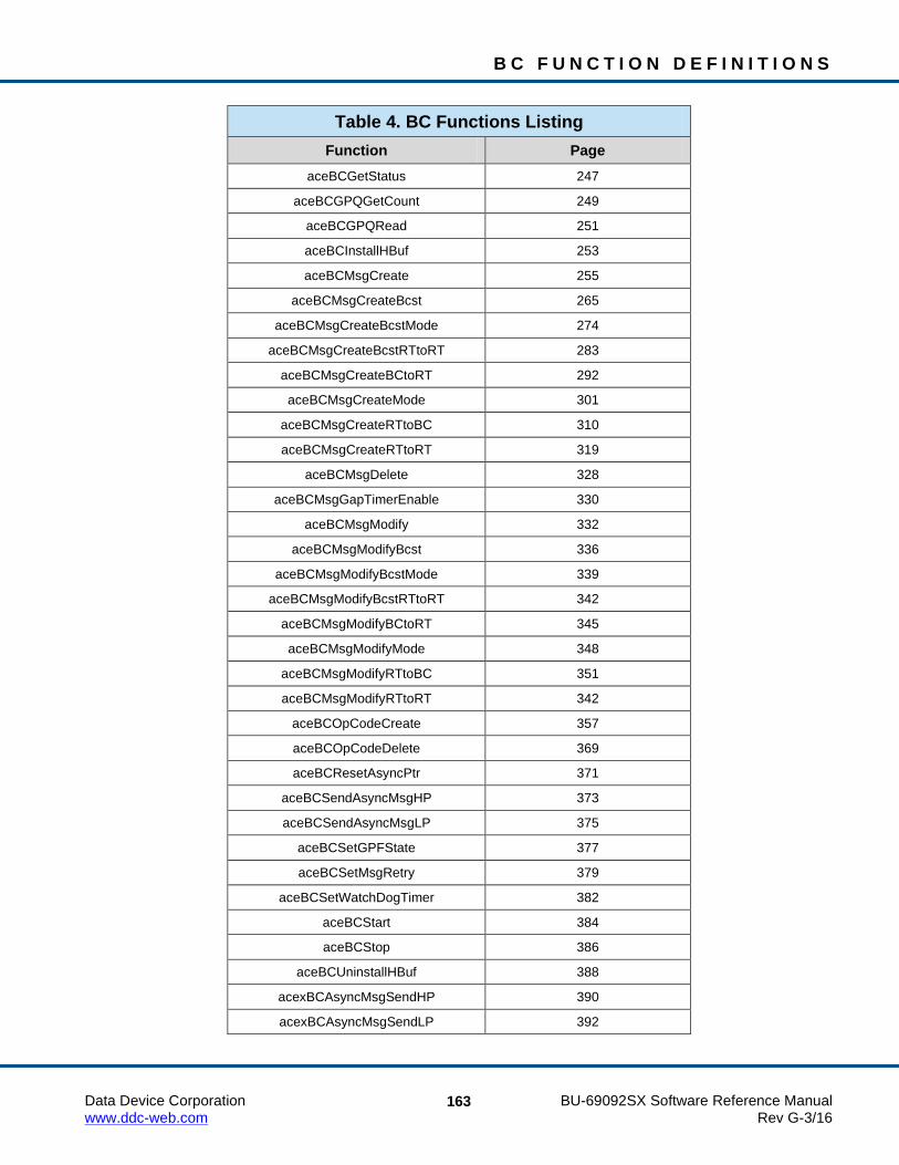
B C F U N C T I O N D E F I N I T I O N S
Data Device Corporation BU-69092SX Software Reference Manual www.ddc-web.com Rev G-3/16
163
Table 4. BC Functions Listing Function Page
aceBCGetStatus 247
aceBCGPQGetCount 249
aceBCGPQRead 251
aceBCInstallHBuf 253
aceBCMsgCreate 255
aceBCMsgCreateBcst 265
aceBCMsgCreateBcstMode 274
aceBCMsgCreateBcstRTtoRT 283
aceBCMsgCreateBCtoRT 292
aceBCMsgCreateMode 301
aceBCMsgCreateRTtoBC 310
aceBCMsgCreateRTtoRT 319
aceBCMsgDelete 328
aceBCMsgGapTimerEnable 330
aceBCMsgModify 332
aceBCMsgModifyBcst 336
aceBCMsgModifyBcstMode 339
aceBCMsgModifyBcstRTtoRT 342
aceBCMsgModifyBCtoRT 345
aceBCMsgModifyMode 348
aceBCMsgModifyRTtoBC 351
aceBCMsgModifyRTtoRT 342
aceBCOpCodeCreate 357
aceBCOpCodeDelete 369
aceBCResetAsyncPtr 371
aceBCSendAsyncMsgHP 373
aceBCSendAsyncMsgLP 375
aceBCSetGPFState 377
aceBCSetMsgRetry 379
aceBCSetWatchDogTimer 382
aceBCStart 384
aceBCStop 386
aceBCUninstallHBuf 388
acexBCAsyncMsgSendHP 390
acexBCAsyncMsgSendLP 392

B C F U N C T I O N D E F I N I T I O N S
Data Device Corporation BU-69092SX Software Reference Manual www.ddc-web.com Rev G-3/16
164
Table 4. BC Functions Listing Function Page
acexBCAsyncQueueInfoHP 394
acexBCAsyncQueueInfoLP 396
acexBCConfigureReplay 398
acexBCContinue 401
acexBCDataArrayCreateBCtoRT 402
acexBCDataArrayDelete 405
acexBCDataArraySend 407
acexBCDataStreamCreateBCRT 409
acexBCDataStreamCreateRTRT 411
acexBCDataStreamDelete 414
acexBCDataStreamReceive 416
acexBCDataStreamSend 418
acexBCDbcDisable 420
acexBCDbcEnable 421
acexBCFrameCreate 422
acexBCGetHbufMsgDecoded 426
acexBCGetHbufMsgsRaw 430
acexBCGetMsgFromIDDecoded 433
acexBCGetMsgFromIDRaw 436
acexBCGetMsgHdrFromIDRaw 438
acexBCGetStatusReplay 440
acexBCImrTrigSelect 442
acexBCMemObjCreate 444
acexBCMemObjDelete 446
acexBCMemWrdCreate 448
acexBCMemWrdDelete 450
acexBCMemWrdRead 452
acexBCMemWrdWrite 454
aceBCMsgErrorDisable 456
acexBCMsgErrorEnable 457
acexBCOpCodeRead 458
acexOpCodeWrite 460
acexBCPause 463
acexBCSetMsgError 464
acexBCSetRespTimeout 466

B C F U N C T I O N D E F I N I T I O N S
Data Device Corporation BU-69092SX Software Reference Manual www.ddc-web.com Rev G-3/16
165
Table 4. BC Functions Listing Function Page
acexBCStartReplay 468
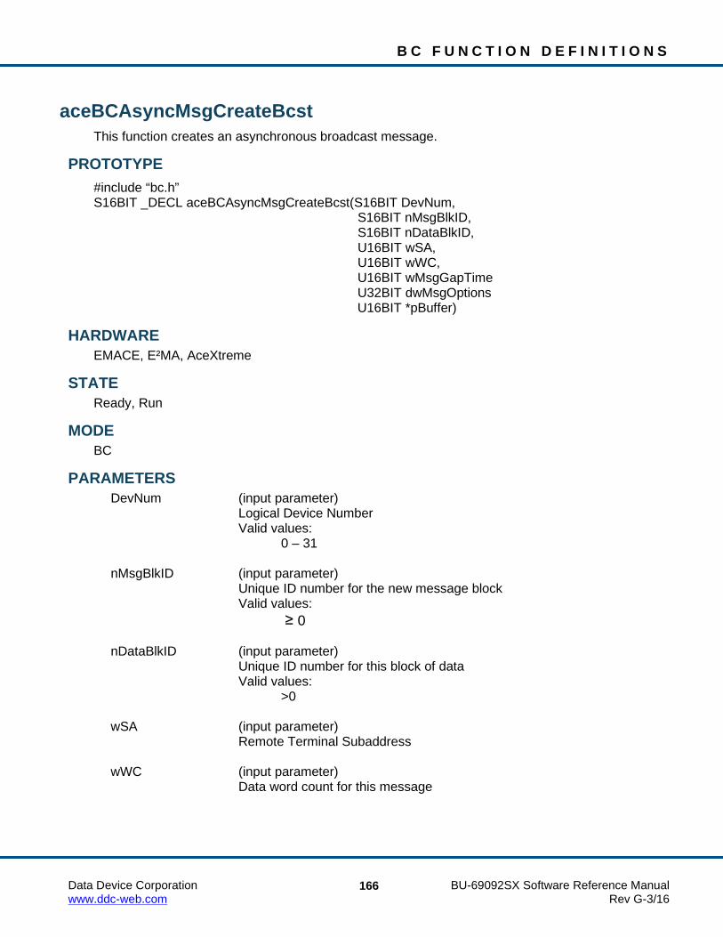
B C F U N C T I O N D E F I N I T I O N S
Data Device Corporation BU-69092SX Software Reference Manual www.ddc-web.com Rev G-3/16
166
aceBCAsyncMsgCreateBcst This function creates an asynchronous broadcast message.
PROTOTYPE #include “bc.h” S16BIT _DECL aceBCAsyncMsgCreateBcst(S16BIT DevNum, S16BIT nMsgBlkID, S16BIT nDataBlkID, U16BIT wSA, U16BIT wWC, U16BIT wMsgGapTime U32BIT dwMsgOptions U16BIT *pBuffer)
HARDWARE EMACE, E²MA, AceXtreme
STATE Ready, Run
MODE BC
PARAMETERS DevNum (input parameter) Logical Device Number Valid values: 0 – 31 nMsgBlkID (input parameter) Unique ID number for the new message block Valid values:
≥ 0 nDataBlkID (input parameter) Unique ID number for this block of data Valid values: >0 wSA (input parameter) Remote Terminal Subaddress wWC (input parameter) Data word count for this message

B C F U N C T I O N D E F I N I T I O N S
Data Device Corporation BU-69092SX Software Reference Manual www.ddc-web.com Rev G-3/16
167
aceBCAsyncMsgCreateBcst (continued) wMsgGapTime (input parameter) The time to next message in µseconds dwMsgOptions (input parameter) See aceBCMsgCreateBcst() for a list of options pBuffer (input parameter) Buffer containing the data words for this message
DESCRIPTION This function creates an asynchronous broadcast message. All parameters will be set up for the Broadcast message based on the dwMsgOptions input parameter. This function calls the aceBCMsgCreateBcst() function and then asynchronously inserts your message when you call one of the asynchronous send routines.
RETURN VALUE ACE_ERR_SUCCESS The function completed successfully ACE_ERR_INVALID_DEVNUM An invalid device number was input by the user ACE_ERR_INVALID_STATE The device is not in a Ready or Run state ACE_ERR_INVALID_MODE The device is not in BC mode ACE_ERR_NOT_ASYNC_MODE The software is not in asynchronous mode. This state must
be selected in the aceBCConfigure() function. ACE_ERR_BC_DBLK_EXISTS The message block specified by the nMsgBlkID input
parameter already exists ACE_ERR_NODE_NOT_FOUND The data block specified by the nDataBlkID cannot be
created. Make sure that this data block has not been previously created with the aceBCDataBlkCreate() function. Asynchronous messages will call the aceBCDataBlkCreate() function internally and this function does not need to be called by the user.
ACE_ERR_BC_DBLK_SIZE The data block size is not valid ACE_ERR_BC_DBLK_ALLOC The message block could not be allocated ACE_ERR_MEMMGR_FAIL The required memory for the message block could not be
allocated

B C F U N C T I O N D E F I N I T I O N S
Data Device Corporation BU-69092SX Software Reference Manual www.ddc-web.com Rev G-3/16
168
aceBCAsyncMsgCreateBcst (continued) EXAMPLE
S16BIT DevNum = 0; S16BIT nResult = 0; U16BIT pBuffer[32]; for (int count=0; count<32; count++) { pBuffer [count]=0x1111; } nResult = aceBCAsyncMsgCreateBcst(S16BIT DevNum, 1, 1, 1, 32, 0, ACE_BCCTRL_CHL_A, pBuffer); if(nResult < 0) {
printf("Error occurred in aceBCAsyncMsgCreateBcst function call \n");
PrintError(nResult); return; }
SEE ALSO aceBCMsgCreateBcst()

B C F U N C T I O N D E F I N I T I O N S
Data Device Corporation BU-69092SX Software Reference Manual www.ddc-web.com Rev G-3/16
169
aceBCAsyncMsgCreateBcstMode This function creates an asynchronous broadcast mode code message.
PROTOTYPE #include “Bc.h” S16BIT _DECL aceBCAsyncMsgCreateBcstMode (S16BIT DevNum, S16BIT nMsgBlkID, S16BIT nDataBlkID, U16BIT wTR, U16BIT wModeCmd, U16BIT wMsgGapTime, U32BIT dwMsgOptions, U16BIT *pBuffer);
HARDWARE EMACE, E²MA, AceXtreme
STATE Ready, Run
MODE BC
PARAMETERS DevNum (input parameter) Logical Device Number Valid values: 0 – 31 nMsgBlkID (input parameter) Unique ID number for the new message block Valid values:
≥ 0 nDataBlkID (input parameter) Unique ID number for this block of data Valid values: >0 wTR (input parameter) Message Transmit/Receive bit Valid Values: ACE_RX_CMD ACE_TX_CMD

B C F U N C T I O N D E F I N I T I O N S
Data Device Corporation BU-69092SX Software Reference Manual www.ddc-web.com Rev G-3/16
170
aceBCAsyncMsgCreateBcstMode (continued) wModeCmd (input parameter) Message Mode Code Command Valid Values: 0 - 31 wMsgGapTime (input parameter) The time to next message in µseconds dwMsgOptions (input parameter) See aceBCMsgCreateBcstMode() for a list of options pBuffer (input parameter) Buffer containing the data words for this message
DESCRIPTION This function creates an asynchronous broadcast mode code message. All parameters will be set up for the Broadcast mode code message based on the dwMsgOptions input parameter. This function calls the aceBCMsgCreateBcstMode() function and then asynchronously inserts your message when you call one of the asynchronous send routines.
RETURN VALUE ACE_ERR_SUCCESS The function completed successfully ACE_ERR_INVALID_DEVNUM An invalid device number was input by the user ACE_ERR_INVALID_STATE The device is not in a Ready or Run state ACE_ERR_INVALID_MODE The device is not in BC mode ACE_ERR_NOT_ASYNC_MODE The software is not in asynchronous mode. This state must
be selected in the aceBCConfigure() function. ACE_ERR_BC_DBLK_EXISTS The message block specified by the nMsgBlkID input
parameter already exists ACE_ERR_NODE_NOT_FOUND The data block specified by the nDataBlkID cannot be
created. Make sure that this data block has not been previously created with the aceBCDataBlkCreate() function. Asynchronous messages will call the aceBCDataBlkCreate() function internally and this function does not need to be called by the user.
ACE_ERR_BC_DBLK_SIZE The data block size is not valid ACE_ERR_BC_DBLK_ALLOC The message block could not be allocated ACE_ERR_MEMMGR_FAIL The required memory for the message block could not be
allocated

B C F U N C T I O N D E F I N I T I O N S
Data Device Corporation BU-69092SX Software Reference Manual www.ddc-web.com Rev G-3/16
171
aceBCAsyncMsgCreateBcstMode (continued) EXAMPLE
S16BIT DevNum = 0; S16BIT nResult = 0; U16BIT pBuffer[32]; for (int count=0; count<32; count++) { pBuffer [count]=0x1111; } nResult = aceBCAsyncMsgCreateBcstMode (S16BIT DevNum, 1, 1, ACE_RX_CMD, 1, 0, ACE_BCCTRL_CHL_A); if(nResult < 0) {
printf("Error occurred in aceBCAsyncMsgCreateBcstMode function call \n");
PrintError(nResult); return; }
SEE ALSO aceBCMsgCreateBcstMode()

B C F U N C T I O N D E F I N I T I O N S
Data Device Corporation BU-69092SX Software Reference Manual www.ddc-web.com Rev G-3/16
172
aceBCAsyncMsgCreateBcstRTtoRT This function creates an asynchronous RT to RT broadcast message.
PROTOTYPE #include “Bc.h” S16BIT _DECL aceBCAsyncMsgCreateBcstRTtoRT( S16BIT DevNum, S16BIT nMsgBlkID, S16BIT nDataBlkID, U16BIT wSARx, U16BIT wWC, U16BIT wRTTx, U16BIT wSATx, U16BIT wMsgGapTime, U32BIT dwMsgOptions, U16BIT *pBuffer);
HARDWARE EMACE, E²MA, AceXtreme
STATE Ready, Run
MODE BC
PARAMETERS DevNum (input parameter) Logical Device Number Valid values: 0 – 31 nMsgBlkID (input parameter) Unique ID number for the new message block Valid values:
≥ 0 nDataBlkID (input parameter) Unique ID number for this block of data Valid values: >0 wSARx (input parameter) RT SA of receiving RT

B C F U N C T I O N D E F I N I T I O N S
Data Device Corporation BU-69092SX Software Reference Manual www.ddc-web.com Rev G-3/16
173
aceBCAsyncMsgCreateBcstRTtoRT (continued) wWC (input parameter) The word count for the message wRTTx (input parameter) RT address of transmitting RT wSATx (input parameter) RT SA of transmitting RT wMsgGapTime (input parameter) The time to next message in µseconds dwMsgOptions (input parameter) See aceBCMsgCreateBcstMode() for a list of options pBuffer (input parameter) Buffer containing the data words for this message
DESCRIPTION This function creates an asynchronous broadcast RT to RT message. All parameters will be set up for the message based on the dwMsgOptions input parameter. This function calls the aceBCMsgCreateBcstRTtoRT() function and then asynchronously inserts your message when you call one of the asynchronous send routines.
RETURN VALUE ACE_ERR_SUCCESS The function completed successfully ACE_ERR_INVALID_DEVNUM An invalid device number was input by the user ACE_ERR_INVALID_STATE The device is not in a Ready or Run state ACE_ERR_INVALID_MODE The device is not in BC mode ACE_ERR_NOT_ASYNC_MODE The software is not in asynchronous mode. This state must
be selected in the aceBCConfigure() function. ACE_ERR_BC_DBLK_EXISTS The message block specified by the nMsgBlkID input
parameter already exists ACE_ERR_NODE_NOT_FOUND The data block specified by the nDataBlkID cannot be
created. Make sure that this data block has not been previously created with the aceBCDataBlkCreate() function. Asynchronous messages will call the aceBCDataBlkCreate() function internally and this function does not need to be called by the user.
ACE_ERR_BC_DBLK_SIZE The data block size is not valid ACE_ERR_BC_DBLK_ALLOC The message block could not be allocated ACE_ERR_MEMMGR_FAIL The required memory for the message block could not be
allocated

B C F U N C T I O N D E F I N I T I O N S
Data Device Corporation BU-69092SX Software Reference Manual www.ddc-web.com Rev G-3/16
174
aceBCAsyncMsgCreateBcstRTtoRT (continued) EXAMPLE
S16BIT DevNum = 0; S16BIT nResult = 0; U16BIT pBuffer[32]; for (int count=0; count<32; count++) { pBuffer [count]=0x1111; } nResult = aceBCAsyncMsgCreateBcstRTtoRT(S16BIT DevNum, 1, 1, 1, 32, 1, 1, 0, ACE_BCCTRL_CHL_A, pBuffer); if(nResult) {
printf("Error occurred in aceBCAsyncMsgCreateBcstRTtoRT function call \n");
PrintError(nResult); return; }
SEE ALSO aceBCMsgCreateBcstRTtoRT()

B C F U N C T I O N D E F I N I T I O N S
Data Device Corporation BU-69092SX Software Reference Manual www.ddc-web.com Rev G-3/16
175
aceBCAsyncMsgCreateBCtoRT This function creates an asynchronous BC to RT message.
PROTOTYPE #include “Bc.h” S16BIT _DECL aceBCAsyncMsgCreateBCtoRT(S16BIT DevNum, S16BIT nMsgBlkID, S16BIT nDataBlkID, U16BIT wRT, U16BIT wSA, U16BIT wWC, U16BIT wMsgGapTime, U32BIT dwMsgOptions, U16BIT *pBuffer);
HARDWARE EMACE, E²MA, AceXtreme
STATE Ready, Run
MODE BC
PARAMETERS DevNum (input parameter) Logical Device Number Valid values: 0 – 31 nMsgBlkID (input parameter) Unique ID number for the new message block Valid values:
≥ 0 nDataBlkID (input parameter) Unique ID number for this block of data Valid values: >0 wRT (input parameter) RT address wSA (input parameter) RT SA

B C F U N C T I O N D E F I N I T I O N S
Data Device Corporation BU-69092SX Software Reference Manual www.ddc-web.com Rev G-3/16
176
aceBCAsyncMsgCreateBCtoRT (continued) wWC (input parameter) The word count for the message wMsgGapTime (input parameter) The time to next message in µseconds dwMsgOptions (input parameter) See aceBCMsgCreateBCtoRT() for a list of options pBuffer (input parameter) Buffer containing the data words for this message
DESCRIPTION This function creates an asynchronous BC to RT message. All parameters will be set up for the message based on the dwMsgOptions input parameter. This function calls the aceBCMsgCreateBCtoRT() function and then asynchronously inserts your message when you call one of the asynchronous send routines.
RETURN VALUE ACE_ERR_SUCCESS The function completed successfully ACE_ERR_INVALID_DEVNUM An invalid device number was input by the user ACE_ERR_INVALID_STATE The device is not in a Ready or Run state ACE_ERR_INVALID_MODE The device is not in BC mode ACE_ERR_NOT_ASYNC_MODE The software is not in asynchronous mode. This state must
be selected in the aceBCConfigure() function. ACE_ERR_BC_DBLK_EXISTS The message block specified by the nMsgBlkID input
parameter already exists ACE_ERR_NODE_NOT_FOUND The data block specified by the nDataBlkID cannot be
created. Make sure that this data block has not been previously created with the aceBCDataBlkCreate() function. Asynchronous messages will call the aceBCDataBlkCreate() function internally and this function does not need to be called by the user.
ACE_ERR_BC_DBLK_SIZE The data block size is not valid ACE_ERR_BC_DBLK_ALLOC The message block could not be allocated ACE_ERR_MEMMGR_FAIL The required memory for the message block could not be
allocated

B C F U N C T I O N D E F I N I T I O N S
Data Device Corporation BU-69092SX Software Reference Manual www.ddc-web.com Rev G-3/16
177
aceBCAsyncMsgCreateBCtoRT (continued) EXAMPLE
S16BIT DevNum = 0; S16BIT nResult = 0; U16BIT pBuffer[32]; for (int count=0; count<32; count++) { pBuffer [count]=0x1111; } nResult = aceBCAsyncMsgCreateBCtoRT(DevNum, 1, 1, 1, 1, 32, 0, ACE_BCCTRL_CHL_A, pBuffer); if(nResult) {
printf("Error occurred in aceBCAsyncMsgCreateBCtoRT function call \n");
PrintError(nResult); return; }
SEE ALSO aceBCMsgCreateBCtoRT()

B C F U N C T I O N D E F I N I T I O N S
Data Device Corporation BU-69092SX Software Reference Manual www.ddc-web.com Rev G-3/16
178
aceBCAsyncMsgCreateMode This function creates an asynchronous mode code message.
PROTOTYPE #include “Bc.h” S16BIT _DECL aceBCAsyncMsgCreateMode(S16BIT DevNum, S16BIT nMsgBlkID, S16BIT nDataBlkID, U16BIT wRT, U16BIT wTR, U16BIT wModeCmd, U16BIT wMsgGapTime, U32BIT dwMsgOptions, U16BIT *pBuffer)
HARDWARE EMACE, E²MA, AceXtreme
STATE Ready, Run
MODE BC
PARAMETERS DevNum (input parameter) Logical Device Number Valid values: 0 – 31 nMsgBlkID (input parameter) Unique ID number for the new message block Valid values:
≥ 0 nDataBlkID (input parameter) Unique ID number for this block of data Valid values: >0 wRT (input parameter) RT address

B C F U N C T I O N D E F I N I T I O N S
Data Device Corporation BU-69092SX Software Reference Manual www.ddc-web.com Rev G-3/16
179
aceBCAsyncMsgCreateMode (continued) wTR (input parameter) Message Transmit/Receive bit Valid Values: ACE_RX_CMD ACE_TX_CMD wModeCmd (input parameter) The mode command to be issued wMsgGapTime (input parameter) The time to next message in µseconds dwMsgOptions (input parameter) See aceBCMsgCreateMode() for a list of options pBuffer (input parameter) Buffer containing the data words for this message
DESCRIPTION This function creates an asynchronous mode code message. All parameters will be set up for the message based on the dwMsgOptions input parameter. This function calls the aceBCMsgCreateMode() function and then asynchronously inserts your message when you call one of the asynchronous send routines.
RETURN VALUE ACE_ERR_SUCCESS The function completed successfully ACE_ERR_INVALID_DEVNUM An invalid device number was input by the user ACE_ERR_INVALID_STATE The device is not in a Ready or Run state ACE_ERR_INVALID_MODE The device is not in BC mode ACE_ERR_NOT_ASYNC_MODE The software is not in asynchronous mode. This state must
be selected in the aceBCConfigure() function. ACE_ERR_BC_DBLK_EXISTS The message block specified by the nMsgBlkID input
parameter already exists ACE_ERR_NODE_NOT_FOUND The data block specified by the nDataBlkID cannot be
created. Make sure that this data block has not been previously created with the aceBCDataBlkCreate() function. Asynchronous messages will call the aceBCDataBlkCreate() function internally and this function does not need to be called by the user.
ACE_ERR_BC_DBLK_SIZE The data block size is not valid ACE_ERR_BC_DBLK_ALLOC The message block could not be allocated ACE_ERR_MEMMGR_FAIL The required memory for the message block could not be
allocated

B C F U N C T I O N D E F I N I T I O N S
Data Device Corporation BU-69092SX Software Reference Manual www.ddc-web.com Rev G-3/16
180
aceBCAsyncMsgCreateMode (continued) EXAMPLE
S16BIT DevNum = 0; S16BIT nResult = 0; U16BIT pBuffer[32]; for (int count=0; count<32; count++) { pBuffer [count]=0x1111; } nResult = aceBCAsyncMsgCreateMode(DevNum, 1, 1, 1, 1, 1, 0, ACE_BCCTRL_CHL_A, pBuffer); if(nResult) {
printf("Error occurred in aceBCAsyncMsgCreateMode function call \n");
PrintError(nResult); return; }
SEE ALSO aceBCMsgCreateMode()

B C F U N C T I O N D E F I N I T I O N S
Data Device Corporation BU-69092SX Software Reference Manual www.ddc-web.com Rev G-3/16
181
aceBCAsyncMsgCreateRTtoBC This function creates an asynchronous RT to BC message.
PROTOTYPE #include “Bc.h” S16BIT _DECL aceBCAsyncMsgCreateRTtoBC(S16BIT DevNum, S16BIT nMsgBlkID, S16BIT nDataBlkID, U16BIT wRT, U16BIT wSA, U16BIT wWC, U16BIT wMsgGapTime, U32BIT dwMsgOptions, U16BIT *pBuffer);
HARDWARE EMACE, E²MA, AceXtreme
STATE Ready, Run
MODE BC
PARAMETERS DevNum (input parameter) Logical Device Number Valid values: 0 – 31 nMsgBlkID (input parameter) Unique ID number for the new message block Valid values:
≥ 0 nDataBlkID (input parameter) Unique ID number for this block of data Valid values: >0 wRT (input parameter) RT address wSA (input parameter) RT SA

B C F U N C T I O N D E F I N I T I O N S
Data Device Corporation BU-69092SX Software Reference Manual www.ddc-web.com Rev G-3/16
182
aceBCAsyncMsgCreateRTtoBC (continued) wWC (input parameter) The word count for the message wMsgGapTime (input parameter) The time to next message in µseconds dwMsgOptions (input parameter) See aceBCMsgCreateRTtoBC() for a list of options pBuffer (input parameter) Buffer containing the data words for this message
DESCRIPTION This function creates an asynchronous RT to BC message. All parameters will be set up for the message based on the dwMsgOptions input parameter. This function calls the aceBCMsgCreateRTtoBC() function and then asynchronously inserts your message when you call one of the asynchronous send routines.
RETURN VALUE ACE_ERR_SUCCESS The function completed successfully ACE_ERR_INVALID_DEVNUM An invalid device number was input by the user ACE_ERR_INVALID_STATE The device is not in a Ready or Run state ACE_ERR_INVALID_MODE The device is not in BC mode ACE_ERR_NOT_ASYNC_MODE The software is not in asynchronous mode. This state must
be selected in the aceBCConfigure() function. ACE_ERR_BC_DBLK_EXISTS The message block specified by the nMsgBlkID input
parameter already exists ACE_ERR_NODE_NOT_FOUND The data block specified by the nDataBlkID cannot be
created. Make sure that this data block has not been previously created with the aceBCDataBlkCreate() function. Asynchronous messages will call the aceBCDataBlkCreate() function internally and this function does not need to be called by the user.
ACE_ERR_BC_DBLK_SIZE The data block size is not valid ACE_ERR_BC_DBLK_ALLOC The message block could not be allocated ACE_ERR_MEMMGR_FAIL The required memory for the message block could not be
allocated

B C F U N C T I O N D E F I N I T I O N S
Data Device Corporation BU-69092SX Software Reference Manual www.ddc-web.com Rev G-3/16
183
aceBCAsyncMsgCreateRTtoBC (continued) EXAMPLE
S16BIT DevNum = 0; S16BIT nResult = 0; U16BIT pBuffer[32]; for (int count=0; count<32; count++) { pBuffer [count]=0x1111; } nResult = aceBCAsyncMsgCreateRTtoBC(DevNum, 1, 1, 1, 1, 32, 0, ACE_BCCTRL_CHL_A, pBuffer); if(nResult) {
printf("Error occurred in aceBCAsyncMsgCreateRTtoBC function call \n");
PrintError(nResult); return; }
SEE ALSO aceBCMsgCreateRTtoBC()

B C F U N C T I O N D E F I N I T I O N S
Data Device Corporation BU-69092SX Software Reference Manual www.ddc-web.com Rev G-3/16
184
aceBCAsyncMsgCreateRTtoRT This function creates an asynchronous RT to RT message.
PROTOTYPE #include “Bc.h” S16BIT _DECL aceBCAsyncMsgCreateRTtoRT(S16BIT DevNum, S16BIT nMsgBlkID, S16BIT nDataBlkID, U16BIT wRTRx, U16BIT wSARx, U16BIT wWC, U16BIT wRTTx, U16BIT wSATx U16BIT wMsgGapTime, U32BIT dwMsgOptions, U16BIT *pBuffer);
HARDWARE EMACE, E²MA, AceXtreme
STATE Ready, Run
MODE BC
PARAMETERS DevNum (input parameter) Logical Device Number Valid values: 0 – 31 nMsgBlkID (input parameter) Unique ID number for the new message block Valid values:
≥ 0 nDataBlkID (input parameter) Unique ID number for this block of data Valid values: >0 wRTRx (input parameter) RT address for receiving RT

B C F U N C T I O N D E F I N I T I O N S
Data Device Corporation BU-69092SX Software Reference Manual www.ddc-web.com Rev G-3/16
185
aceBCAsyncMsgCreateRTtoRT (continued) wSARx (input parameter) RT SA for receiving RT wWC (input parameter) The word count for the message wRTTx (input parameter) RT address for transmitting RT wSATx (input parameter) RT SA for transmitting RT wMsgGapTime (input parameter) The time to next message in µseconds dwMsgOptions (input parameter) See aceBCMsgCreateRTtoRT() for a list of options pBuffer (input parameter) Buffer containing the data words for this message
DESCRIPTION This function creates an asynchronous RT to RT message. All parameters will be set up for the message based on the dwMsgOptions input parameter. This function calls the aceBCMsgCreateRTtoRT() function and then asynchronously inserts your message when you call one of the asynchronous send routines.
RETURN VALUE ACE_ERR_SUCCESS The function completed successfully ACE_ERR_INVALID_DEVNUM An invalid device number was input by the user ACE_ERR_INVALID_STATE The device is not in a Ready or Run state ACE_ERR_INVALID_MODE The device is not in BC mode ACE_ERR_NOT_ASYNC_MODE The software is not in asynchronous mode. This state must
be selected in the aceBCConfigure() function. ACE_ERR_BC_DBLK_EXISTS The message block specified by the nMsgBlkID input
parameter already exists ACE_ERR_NODE_NOT_FOUND The data block specified by the nDataBlkID cannot be
created. Make sure that this data block has not been previously created with the aceBCDataBlkCreate() function. Asynchronous messages will call the aceBCDataBlkCreate() function internally and this function does not need to be called by the user.
ACE_ERR_BC_DBLK_SIZE The data block size is not valid ACE_ERR_BC_DBLK_ALLOC The message block could not be allocated ACE_ERR_MEMMGR_FAIL The required memory for the message block could not be
allocated

B C F U N C T I O N D E F I N I T I O N S
Data Device Corporation BU-69092SX Software Reference Manual www.ddc-web.com Rev G-3/16
186
aceBCAsyncMsgCreateRTtoRT (continued) EXAMPLE
S16BIT DevNum = 0; S16BIT nResult = 0; U16BIT pBuffer[32]; for (int count=0; count<32; count++) { pBuffer [count]=0x1111; } nResult = aceBCAsyncMsgCreateRTtoRT(DevNum, 1, 1, 1, 1, 32, 2, 1, 0, ACE_BCCTRL_CHL_A, pBuffer); if(nResult) {
printf("Error occurred in aceBCAsyncMsgCreateRTtoRT function call \n");
PrintError(nResult); return; }
SEE ALSO aceBCMsgCreateRTtoRT()

B C F U N C T I O N D E F I N I T I O N S
Data Device Corporation BU-69092SX Software Reference Manual www.ddc-web.com Rev G-3/16
187
aceBCEmptyAsyncList This function clears the Asynchronous Message Queue.
PROTOTYPE #include “Bc.h” S16BIT _DECL aceBCEmptyAsyncList(S16BIT DevNum);
HARDWARE EMACE, E²MA, AceXtreme
STATE Ready, Run
MODE BC
PARAMETERS DevNum (input parameter) Logical Device Number Valid values: 0 – 31
DESCRIPTION This function clears the Asynchronous Message Queue, removing any Asynchronous Messages that have not yet been sent. By calling this function, any Low-Priority and High-Priority Asynchronous Messages that have been sent will be removed from the bus list.
RETURN VALUE ACE_ERR_SUCCESS The function completed successfully ACE_ERR_INVALID_DEVNUM An invalid device number was input by the user ACE_ERR_INVALID_STATE The device is not in a Ready or Run state ACE_ERR_INVALID_MODE The device is not in BC mode ACE_ERR_NOT_ASYNC_MODE The software is not in asynchronous mode
This state must be selected in the aceBCConfigure() function
ACE_ERR_PARAMETER An invalid input parameter was input by the user ACE_ERR_BC_DBLK_EXISTS The message block specified by the nMsgBlkID input
parameter already exists ACE_ERR_NODE_NOT_FOUND The data block specified in the nDataBlkID cannot
be created. Make sure that this data block has not been previously created with the aceBCDataBlkCreate() function. Asynchronous messages will call the aceBCDataBlkCreate() function internally and this function does not need to be called by the user.

B C F U N C T I O N D E F I N I T I O N S
Data Device Corporation BU-69092SX Software Reference Manual www.ddc-web.com Rev G-3/16
188
aceBCEmptyAsyncList (continued) ACE_ERR_BC_DBLK_SIZE The data block size is not valid ACE_ERR_BC_DBLK_ALLOC The message could not be allocated ACE_ERR_MEMMGR_FAIL The required memory for the message block could not be
allocated
EXAMPLE S16BIT DevNum = 0; S16BIT nResult = 0; nResult = aceBCEmptyAsyncList(DevNum); if(nResult < 0) { printf(“Error occurred in aceBCEmptyAsyncList function \n”); PrintOutError(nResult); return; }
SEE ALSO aceBCSendAsyncMsgLP() aceBCSendAsyncMsgHP() aceBCConfigure()

B C F U N C T I O N D E F I N I T I O N S
Data Device Corporation BU-69092SX Software Reference Manual www.ddc-web.com Rev G-3/16
189
aceBCConfigure This function configures the Bus Controller operation.
PROTOTYPE #include “bc.h” S16BIT _DECL aceBCConfigure(S16BIT DevNum, U32BIT dwOptions);
HARDWARE EMACE, E²MA, AceXtreme
STATE Ready
MODE BC
PARAMETERS DevNum (input parameter) Logical Device Number Valid values: 0 – 31 dwOptions BC operation options Valid values: 0 No Special Options Selected ACE_BC_ASYNC_LMODE This option selects low priority asynchronous messaging mode.
This mode allows you to create a queue of messages that can be sent at the end of the current frame only if frame time permits with the aceBCSendAsyncMsgLP() function.
ACE_BC_ASYNC_HMODE This option selects high priority asynchronous messaging mode.
This mode allows you to create asynchronous messages and send them onto the bus one at a time at the end of the current synchronous message with the aceBCSendAsyncMsgHP() function.

B C F U N C T I O N D E F I N I T I O N S
Data Device Corporation BU-69092SX Software Reference Manual www.ddc-web.com Rev G-3/16
190
aceBCConfigure (continued) ACE_BC_ASYNC_BOTH This options selects high and low priority messaging. This allows
you to mix high and low priority messages. Please note that when asynchronous messages are created in this mode, there is no high or low priority designation. If you call the aceBCSendAsyncMsgLP() function then all previously created asynchronous messages will be sent at the end of the current frame if the frame timer permits. The aceBCSendAsyncMsgHP() function allows you to specify a specific message by inputting the unique message id number.
Note: The following options are only supported by AceXtreme devices:
ACEX_BC_GPQ_SZ_64, ACEX_BC_GPQ_SZ_256, ACEX_BC_ASYNC_SZ_LP_32, ACEX_BC_ASYNC_SZ_LP_64,
ACEX_BC_ASYNC_SZ_LP_128, ACEX_BC_ASYNC_SZ_LP_256, ACEX_BC_ASYNC_SZ_LP_512 ACEX_BC_ASYNC_SZ_HP_32, ACEX_BC_ASYNC_SZ_HP_64, ACEX_BC_ASYNC_SZ_HP_128, ACEX_BC_ASYNC_SZ_HP_256, ACEX_BC_ASYNC_SZ_HP_512 ACEX_BC_RESP_GAP_CHECK
ACEX_BC_BCST_STATUS_CHECK ACEX_BC_INTERMSG_INACTIVE_BC ACEX_BC_SIMUL_BUS_TX ACEX_BC_INTERMSG_GAP_TIME ACEX_BC_TO_ACTIVATE
Note: The ACE_BC_ASYNC_LMODE, ACE_BC_ASYNC_HMODE, and ACE_BC_ASYNC_BOTH options are only supported by EMACE and E²MA Devices.
DESCRIPTION This function configures the Bus Controller operation. Data structures and memory allocations are returned to an initialized state. All existing messages, data blocks, minor frames, and major frames are deleted from the specified device.

B C F U N C T I O N D E F I N I T I O N S
Data Device Corporation BU-69092SX Software Reference Manual www.ddc-web.com Rev G-3/16
191
aceBCConfigure (continued) RETURN VALUE
ACE_ERR_SUCCESS The function completed successfully ACE_ERR_INVALID_DEVNUM An invalid device number was input to this function ACE_ERR_INVALID_STATE The device is not in a Ready state ACE_ERR_INVALID_MODE The device is not in BC mode ACE_ERR_INVALID_MALLOC The device failed to allocate memory for the BC structure ACE_ERR_MEMMGR_FAIL Memory allocation could not be completed
EXAMPLE S16BIT DevNum = 0; S16BIT nResult = 0; nResult = aceBCConfigure(DevNum,0); if(nResult < 0) { printf(“Error in aceBCConfigure() function \n”); PrintOutError(nResult); return; }
SEE ALSO None

B C F U N C T I O N D E F I N I T I O N S
Data Device Corporation BU-69092SX Software Reference Manual www.ddc-web.com Rev G-3/16
192
aceBCCreateImageFiles This function allows users to create image files for their code.
PROTOTYPE #include “bc.h” S16BIT _DECL aceBCCreateImageFiles(S16BIT DevNum, S16BIT nMjrFrameID, char *pszIFile, char *pszHFile);
HARDWARE EMACE, E²MA, AceXtreme
STATE Ready
MODE BC
PARAMETERS DevNum (input parameter) Logical Device Number Valid values: 0 – 31 nMjrFrameID (input parameter) Handle to the major frame operation structures pszIFile (input parameter) Pointer to a null terminated string designating the image file name to be generated pszHFile (input parameter) Pointer to a null terminated string designating the header file name to be generated
DESCRIPTION This function outputs two files. The first is a binary image of the target hardware's memory. The second is a 'C' header file that contains all offsets and sample functions that allow memory to be accessed easily in an embedded system.

B C F U N C T I O N D E F I N I T I O N S
Data Device Corporation BU-69092SX Software Reference Manual www.ddc-web.com Rev G-3/16
193
aceBCCreateImageFiles (continued) RETURN VALUE
ACE_ERR_SUCCESS The function completed successfully ACE_ERR_INVALID_DEVNUM An invalid device number was input to this function ACE_ERR_INVALID_STATE The device is not in the Ready state ACE_ERR_INVALID_MODE The device is not in BC mode ACE_ERR_PARAMETER The pszIFile pointer or the pszHFile pointer input by
the user is Null ACE_ERR_NODE_NOT_FOUND A major frame specified by nMjrFrameID could not
be found ACE_ERR_FRAME_NOT_MAJOR The frame specified by the nMjrFrameID parameter
is not a major frame ACE_ERR_UNRES_DATABLK The function failed to resolve the addresses for all
of the message data pointers
EXAMPLE // after full setup of messages and frames S16BIT DevNum = 0; S16BIT nResult = 0; nResult = aceBCCreateImageFiles(DevNum, 4, "bcimage.bin", "bcimage.h"); if(nResult < 0) { printf(“Error in aceBCCreateImageFiles() function \n”); PrintOutError(nResult); return; }
SEE ALSO None
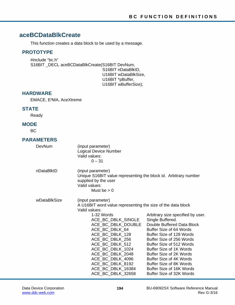
B C F U N C T I O N D E F I N I T I O N S
Data Device Corporation BU-69092SX Software Reference Manual www.ddc-web.com Rev G-3/16
194
aceBCDataBlkCreate This function creates a data block to be used by a message.
PROTOTYPE #include “bc.h” S16BIT _DECL aceBCDataBlkCreate(S16BIT DevNum, S16BIT nDataBlkID, U16BIT wDataBlkSize, U16BIT *pBuffer, U16BIT wBufferSize);
HARDWARE EMACE, E²MA, AceXtreme
STATE Ready
MODE BC
PARAMETERS DevNum (input parameter) Logical Device Number Valid values: 0 – 31 nDataBlkID (input parameter) Unique S16BIT value representing the block id. Arbitrary number supplied by the user Valid values: Must be > 0 wDataBlkSize (input parameter) A U16BIT word value representing the size of the data block Valid values: 1-32 Words Arbitrary size specified by user. ACE_BC_DBLK_SINGLE Single Buffered. ACE_BC_DBLK_DOUBLE Double Buffered Data Block ACE_BC_DBLK_64 Buffer Size of 64 Words ACE_BC_DBLK_128 Buffer Size of 128 Words ACE_BC_DBLK_256 Buffer Size of 256 Words ACE_BC_DBLK_512 Buffer Size of 512 Words ACE_BC_DBLK_1024 Buffer Size of 1K Words ACE_BC_DBLK_2048 Buffer Size of 2K Words ACE_BC_DBLK_4096 Buffer Size of 4K Words ACE_BC_DBLK_8192 Buffer Size of 8K Words ACE_BC_DBLK_16384 Buffer Size of 16K Words ACE_BC_DBLK_32658 Buffer Size of 32K Words

B C F U N C T I O N D E F I N I T I O N S
Data Device Corporation BU-69092SX Software Reference Manual www.ddc-web.com Rev G-3/16
195
aceBCDataBlkCreate (continued) pBuffer (input parameter) A pointer to data to be loaded into the data block at creation Valid values: Address of user buffer wBufferSize (input parameter) Number of words to be copied from user buffer to newly created data block Valid values: wBufferSize must be less than or equal to the size of the buffer and
the size of the data block.
DESCRIPTION This function allocates a data block to be used by a message. The wDataBlkSize value can be 1-32 words long, single or double buffered. For AceXtreme devices, the maximum number of data blocks available is limited to 2047.
RETURN VALUE ACE_ERR_SUCCESS The function completed successfully ACE_ERR_INVALID_DEVNUM An invalid device number was input to this function ACE_ERR_INVALID_STATE The device is not in a Ready state ACE_ERR_INVALID_MODE The device is not in BC mode ACE_ERR_PARAMETER The nDataBlkID and/or the nDataBlkSize and/or the
wBufferSize parameter input by the user contains an incorrect value
ACE_ERR_BC_DBLK_EXISTS The specified ID input by the user in the nDataBlkID parameter already exists
ACE_ERR_BC_DBLK_ALLOC The data block could not be created ACE_ERR_MEMMGR_FAIL Memory required for the data block could not be allocated
EXAMPLE // Create 1 data block, 32 words, double buffered S16BIT DevNum = 0; S16BIT DBLK1 = 1; S16BIY nResult = 0; U16BIT pBuffer[32] = {1, 2, 3, 4, 5, 6, 7, 8, 9, 0xA,0xB, 0xC, 0xD, 0xE, 0xF, 0x1001, 0x1002, 0x1003, 0x1004, 0x1005, 0x1006, 0x1007, 0x1008, 0x1009, 0x100A, 0x100B, 0x100C, 0x100D, 0x100E, 0x100F}; nResult = aceBCDataBlkCreate(DevNum,DBLK1,ACE_BC_DBLK_DOUBLE,pBuffer,32); if(nResult < 0) { printf(“Error in aceBCDataBlkCreate() function \n”); PrintOutError(nResult); return; }

B C F U N C T I O N D E F I N I T I O N S
Data Device Corporation BU-69092SX Software Reference Manual www.ddc-web.com Rev G-3/16
196
aceBCDataBlkCreate (continued) SEE ALSO
aceBCDataBlkDelete()

B C F U N C T I O N D E F I N I T I O N S
Data Device Corporation BU-69092SX Software Reference Manual www.ddc-web.com Rev G-3/16
197
aceBCDataBlkDelete This function deletes a previously defined data block.
PROTOTYPE #include “bc.h” S16BIT _DECL aceBCDataBlkDelete(S16BIT DevNum, S16BIT nDataBlkID);
HARDWARE EMACE, E²MA, AceXtreme
STATE Ready
MODE BC
PARAMETERS DevNum (input parameter) Logical Device Number Valid values: 0 – 31 nDataBlkID (input parameter) A unique S16BIT word value representing the block ID to be deleted. Valid values: A previously defined ID >0
DESCRIPTION This function removes a data block from memory and frees all resources associated with it.
RETURN VALUE ACE_ERR_SUCCESS The function completed successfully ACE_ERR_INVALID_DEVNUM An invalid device number was input by the user ACE_ERR_INVALID_STATE The device is not in a Ready state ACE_ERR_INVALID_MODE The device is not in BC mode ACE_ERR_PARAMETER The nDataBlkID parameter contains an incorrect value ACE_ERR_NODE_NOT_FOUND The data block specified by nDataBlkID does not exist

B C F U N C T I O N D E F I N I T I O N S
Data Device Corporation BU-69092SX Software Reference Manual www.ddc-web.com Rev G-3/16
198
aceBCDataBlkDelete (continued) EXAMPLE
S16BIT DevNum = 0; S16BIT nDataBlkID = 1; S16BIT nResult = 0; aceBCDataBlkDelete(DevNum,nDataBlkID); if(nResult < 0) { printf(“Error in aceBCDataBlkDelete() function \n”); PrintOutError(nResult); return; }
SEE ALSO aceBCDataBlkCreate()

B C F U N C T I O N D E F I N I T I O N S
Data Device Corporation BU-69092SX Software Reference Manual www.ddc-web.com Rev G-3/16
199
aceBCDataBlkRead This function reads a data block.
PROTOTYPE #include “bc.h” S16BIT _DECL aceBCDataBlkRead(S16BIT DevNum, S16BIT nDataBlkID, U16BIT *pBuffer, U16BIT wBufferSize, U16BIT wOffset);
HARDWARE EMACE, E²MA, AceXtreme
STATE Ready, Run
MODE BC
PARAMETERS DevNum (input parameter) Logical Device Number Valid values: 0 – 31 nDataBlkID (input parameter) A unique S16BIT word value representing the data block id to be read Valid values: A previously defined data block ID >0 pBuffer (output parameter) Pointer to a buffer that will hold the data read from the data block wBufferSize (input parameter) Number of words to be read from the data block Valid values: Must be < buffer size and data block size wOffset (input parameter) Word number offset to start reading from the data block Valid values: Must be < data block size

B C F U N C T I O N D E F I N I T I O N S
Data Device Corporation BU-69092SX Software Reference Manual www.ddc-web.com Rev G-3/16
200
aceBCDataBlkRead (continued) DESCRIPTION
This function reads a data block to a buffer given the data block ID. The number of words will be read starting at an offset from the beginning of the data block. The buffer will contain the raw unformatted 16-bit words contained in the data block.
RETURN VALUE S16BIT The number of data words read ACE_ERR_INVALID_DEVNUM An invalid device number was input by the user ACE_ERR_INVALID_STATE The device is not in a Ready or Run state ACE_ERR_INVALID_MODE The device is not in BC mode ACE_ERR_PARAMETER The nDataBlkID, wBufferSize, wOffset, and/or
pBuffer parameter(s) input by the user contain an incorrect value
ACE_ERR_NODE_NOT_FOUND The data block ID specified by the nDataBlkID parameter input by the user does not exist
EXAMPLE S16BIT DevNum = 0; S16BIT nDataBlkID = 1; S16BIT nResult = 0; U16BIT pBuffer[32]; U16BIT wBufferSize = 20; U16BIT wOffset = 10; NResult = aceBCDataBlkRead(DevNum, nDataBlkID, pBuffer, wBufferSize, wOffset); if(nResult < 0) { printf(“Error in aceBCDataBlkRead() function \n”); PrintOutError(nResult); return; }
SEE ALSO aceBCDataBlkWrite()

B C F U N C T I O N D E F I N I T I O N S
Data Device Corporation BU-69092SX Software Reference Manual www.ddc-web.com Rev G-3/16
201
aceBCDataBlkRead32 This function reads a data block 32-bits at a time from the 1553 hardware device.
PROTOTYPE #include “bc.h” S16BIT _DECL aceBCDataBlkRead32(S16BIT DevNum, S16BIT nDataBlkID, U16BIT *pBuffer, U16BIT wBufferSize, U16BIT wOffset);
HARDWARE EMACE, E²MA, AceXtreme
STATE Ready, Run
MODE BC
PARAMETERS DevNum (input parameter) Logical Device Number Valid values: 0 – 31 nDataBlkID (input parameter) A unique S16BIT word value representing the data block id to be read Valid values: A previously defined data block ID >0 pBuffer (output parameter) Pointer to a buffer that will hold the data read from the data block wBufferSize (input parameter) Number of words to be read from the data block Valid values: Must be < buffer size and data block size wOffset (input parameter) Word number offset to start reading from the data block Valid values: Must be < data block size

B C F U N C T I O N D E F I N I T I O N S
Data Device Corporation BU-69092SX Software Reference Manual www.ddc-web.com Rev G-3/16
202
aceBCDataBlkRead32 (continued) DESCRIPTION
This function reads a data block to a buffer given the data block ID. The number of words will be read starting at an offset from the beginning of the data block. The buffer will contain the raw unformatted 16-bit words contained in the data block. This function will read memory 32-bits at a time. When compared to aceBCDataBlkRead(), this function makes more efficient use of PCI transfers. This is beneficial for real time systems, having the effect of lowering the demand on the host CPU.
RETURN VALUE S16BIT The number of data words read ACE_ERR_INVALID_DEVNUM An invalid device number was input by the user ACE_ERR_INVALID_STATE The device is not in a Ready or Run state ACE_ERR_INVALID_MODE The device is not in BC mode ACE_ERR_PARAMETER The nDataBlkID, wBufferSize, wOffset, and/or
pBuffer parameter(s) input by the user contain an incorrect value
ACE_ERR_NODE_NOT_FOUND The data block ID specified by the nDataBlkID parameter input by the user does not exist
EXAMPLE S16BIT DevNum = 0; S16BIT nDataBlkID = 1; S16BIT nResult = 0; U16BIT pBuffer[32]; U16BIT wBufferSize = 20; U16BIT wOffset = 10; NResult = aceBCDataBlkRead32(DevNum, nDataBlkID, pBuffer, wBufferSize, wOffset); if(nResult < 0) { printf(“Error in aceBCDataBlkRead32() function \n”); PrintOutError(nResult); return; }
SEE ALSO aceBCDataBlkRead() aceBCDataBlkWrite()

B C F U N C T I O N D E F I N I T I O N S
Data Device Corporation BU-69092SX Software Reference Manual www.ddc-web.com Rev G-3/16
203
aceBCDataBlkWrite This function will write data to a data block.
PROTOTYPE #include “bc.h” S16BIT _DECL aceBCDataBlkWrite(S16BIT DevNum, S16BIT nDataBlkID, U16BIT *pBuffer, U16BIT wBufferSize, U16BIT wOffset);
HARDWARE EMACE, E²MA, AceXtreme
STATE Ready, Run
MODE BC
PARAMETERS DevNum (input parameter) Logical Device Number Valid values: 0 – 31 nDataBlkID (input parameter) A unique S16BIT word value representing the block id to be written to Valid values: A previously defined ID >0 pBuffer (input parameter) Pointer to a buffer that holds the data that will get written to the data block wBufferSize (input parameter) Number of words to be written to the data block Valid values: Must be < buffer size and data block size wOffset (input parameter) Data block word number offset to start writing into the data block Valid values: Must be < data block size

B C F U N C T I O N D E F I N I T I O N S
Data Device Corporation BU-69092SX Software Reference Manual www.ddc-web.com Rev G-3/16
204
aceBCDataBlkWrite (continued) DESCRIPTION
This function writes data to a data block from a user provided buffer given the data block ID. The number of words will be written starting at the user specified offset from the beginning of the data block.
RETURN VALUE ACE_ERR_SUCCESS The function completed successfully ACE_ERR_INVALID_DEVNUM An invalid device number was input to this function ACE_ERR_INVALID_STATE The device is not in a Ready or Run state ACE_ERR_INVALID_MODE The device is not in BC mode ACE_ERR_PARAMETER The nDataBlkID, wBufferSize, wOffset, and/or
pBuffer parameters input by the user contain an incorrect value
ACE_ERR_NODE_NOT_FOUND The data block ID specified by the nDataBlkID parameter input by the user does not exist
EXAMPLE S16BIT DevNum = 0; S16BIT nDataBlkID = 1; S16BIT nResult = 0; U16BIT wBufferSize = 32; U16BIT wOffset = 10; U16BIT pBuffer1[32] = {1, 2, 3, 4, 5, 6, 7, 8, 9, 0xA, 0xB, 0xC, 0xD, 0xE, 0xF, 0x1001, 0x1002, 0x1003, 0x1004, 0x1005, 0x1006, 0x1007, 0x1008, 0x1009, 0x100A, 0x100B, 0x100C, 0x100D, 0x100E, 0x100F}; nResult = aceBCDataBlkWrite(DevNum, nDataBlkID, pBuffer1, wBufferSize, wOffset); if(nResult < 0) { printf(“Error in aceBCDataBlkWrite() function \n”); PrintOutError(nResult); return; }
SEE ALSO aceBCDataBlkRead()

B C F U N C T I O N D E F I N I T I O N S
Data Device Corporation BU-69092SX Software Reference Manual www.ddc-web.com Rev G-3/16
205
aceBCDecodeRawMsg This function converts raw 16-bit messages to formatted fields in a MSGSTRUCT structure.
PROTOTYPE #include “bc.h” S16BIT _DECL aceBCDecodeRawMsg(S16BIT DevNum, U16BIT *pBuffer, MSGSTRUCT *pMsg);
HARDWARE EMACE, E²MA, AceXtreme
STATE Ready, Run
MODE BC
PARAMETERS DevNum (input parameter) Logical Device Number Valid values: 0 – 31 pBuffer (input parameter) This is a pointer to the buffer that contains the raw 16-bit stack message information. pMsg (output parameter) This is a pointer to a MSGSTRUCT structure that will contain the decoded message information formatted in the fields contained in the MSGSTRUCT structure. The table below lists all member variables that exist in the MSGSTRUCT structure along with their definition.
Member Variable
Name Definition
wBlkSts Contains the block status word of the message
wTimeTag Contains the time tag of the message
wCmdWrd1 Contains the command word
wCmdWrd2 Contains the second command word for RT to RT transfers
wCmdWrd1Flg Indicates the validity of the first command word (1 = valid)
wCmdWrd2Flg Indicates the validity of the second command word (1 = valid)
wStsWrd1 Contains first status word

B C F U N C T I O N D E F I N I T I O N S
Data Device Corporation BU-69092SX Software Reference Manual www.ddc-web.com Rev G-3/16
206
aceBCDecodeRawMsg (continued) Member Variable
Name Definition
wStsWrd2 Contains second status word
wStsWrd1Flg Indicates the validity of the first status word (1 = valid)
wStsWrd2Flg Indicates the validity of the second status word (1 = valid)
wWordCount Contains the number of valid data words
aDataWrds[32] An array that will contain the data words
wBCCtrlWrd Contains the BC Control Word for BC mode messages only
wBCGapTime Contains the message gap time only for BC
wBCLoopBack1 Contains the first looped back word for BC mode messages only
wTimeTag2
Not used in BC Mode. BC Time Tag is only 16 bits
wBCLoopBack1Flg Indicates validity of first loop back word for BC mode message only
wTimeTag3
Not used in BC Mode. BC Time Tag is only 16 bits
DESCRIPTION This function takes a buffer and decodes the raw message it contains into a decoded MSGSTRUCT structure. The raw message would be the data read directly from the Bus Controller messages. The MSGSTRUCT structure contains easily addressable elements of the message.
RETURN VALUE ACE_ERR_SUCCESS This function completed successfully ACE_ERR_INVALID_DEVNUM An invalid device number was input to this function ACE_ERR_INVALID_STATE The device is not in a Ready or Run state ACE_ERR_INVALID_MODE The device is not in BC mode ACE_ERR_MSGSTRUCT The pMsg parameter input by the user is Null ACE_ERR_INVALID_BUF The pBuffer parameter input by the user is Null
EXAMPLE S16BIT DevNum = 0; S16BIT nResult = 0; MSGSTRUCT *pMsg; U16BIT *pBuffer; nResult = aceBCDecodeRawMsg(DevNum, pBuffer, pMsg); if(nResult < 0) { printf(“Error in aceBCDataBlkWrite() function \n”); PrintOutError(nResult); return; }

B C F U N C T I O N D E F I N I T I O N S
Data Device Corporation BU-69092SX Software Reference Manual www.ddc-web.com Rev G-3/16
207

B C F U N C T I O N D E F I N I T I O N S
Data Device Corporation BU-69092SX Software Reference Manual www.ddc-web.com Rev G-3/16
208
aceBCDecodeRawMsg (continued) SEE ALSO
aceBCGetMsgFromIDRaw() aceBCGetMsgFromIDDecoded()

B C F U N C T I O N D E F I N I T I O N S
Data Device Corporation BU-69092SX Software Reference Manual www.ddc-web.com Rev G-3/16
209
aceBCDisableMessage This function disables a synchronous message from being transmitted.
PROTOTYPE #include “bc.h” S16BIT _DECL aceBCDisableMessage(S16BIT DevNum, U16BIT wMsgNum, BOOL bDisable);
HARDWARE EMACE, E²MA, AceXtreme
STATE Run
MODE BC
PARAMETERS DevNum (input parameter) Logical Device Number Valid values: 0 – 31 wMsgNum (input parameter) ID number of the message being disabled bDisable (input parameter) Enable = 0 (FALSE) Disable = 1 (TRUE)
DESCRIPTION This function disables a synchronous message from being transmitted.
RETURN VALUE ACE_ERR_SUCCESS This function completed successfully ACE_ERR_INVALID_DEVNUM An invalid device number was input to this function ACE_ERR_INVALID_STATE The device is not in Run state ACE_ERR_INVALID_MODE The device is not in BC mode ACE_ERR_UNRES_MSGBLK The specified message ID does not exist ACE_ERR_PARAMETER The bDisable parameter is not valid

B C F U N C T I O N D E F I N I T I O N S
Data Device Corporation BU-69092SX Software Reference Manual www.ddc-web.com Rev G-3/16
210
aceBCDisableMessage (continued) EXAMPLE
S16BIT DevNum = 0; S16BIT nResult = 0; nResult = aceBCDisableMessage(DevNum, MSG_ID, TRUE); if(nResult < 0) { printf(“Error in aceBCDisableMessage() function \n”); PrintOutError(nResult); return; }
SEE ALSO None

B C F U N C T I O N D E F I N I T I O N S
Data Device Corporation BU-69092SX Software Reference Manual www.ddc-web.com Rev G-3/16
211
aceBCExtTriggerDisable This function disables the BC external trigger feature.
PROTOTYPE #include “bc.h” S16BIT _DECL aceBCExtTriggerDisable(S16BIT DevNum);
HARDWARE EMACE, E²MA, AceXtreme
STATE Ready, Run
MODE BC
PARAMETERS DevNum (input parameter) Logical Device Number Valid values: 0 – 31
DESCRIPTION This function disables disables the BC external trigger feature.
RETURN VALUE ACE_ERR_SUCCESS This function completed successfully ACE_ERR_INVALID_DEVNUM An invalid device number was input to this function ACE_ERR_INVALID_STATE The device is not in a Ready or Run state
EXAMPLE S16BIT DevNum = 0; S16BIT nResult = 0; nResult = aceBCExtTriggerDisable (DevNum); if(nResult < 0) { printf(“Error in aceBCExtTriggerDisable() function \n”); PrintOutError(nResult); return; }
SEE ALSO aceBCExtTriggerEnable()

B C F U N C T I O N D E F I N I T I O N S
Data Device Corporation BU-69092SX Software Reference Manual www.ddc-web.com Rev G-3/16
212
aceBCExtTriggerEnable This function enables BC external trigger feature.
PROTOTYPE #include “bc.h” S16BIT _DECL aceBCExtTriggerEnable(S16BIT DevNum, BOOLEAN bOnStart);
HARDWARE EMACE, E²MA, AceXtreme
STATE Ready, Run
MODE BC
PARAMETERS DevNum (input parameter) Logical Device Number Valid values: 0 – 31 bOnStart (input parameter) TRUE if BC will wait for external trigger signal before it starts to send message FALSE otherwise
DESCRIPTION This function enables BC external trigger feature and specifies if BC will wait for external trigger signal before it starts to send message.
RETURN VALUE ACE_ERR_SUCCESS This function completed successfully ACE_ERR_INVALID_DEVNUM An invalid device number was input to this function ACE_ERR_INVALID_STATE The device is not in a Ready or Run state ACE_ERR_NOT_SUPPORTED The device does not support this feature

B C F U N C T I O N D E F I N I T I O N S
Data Device Corporation BU-69092SX Software Reference Manual www.ddc-web.com Rev G-3/16
213
aceBCExtTriggerEnable (continued) EXAMPLE
S16BIT DevNum = 0; S16BIT nResult = 0; nResult = aceBCExtTriggerEnable (DevNum, TRUE); if(nResult < 0) { printf(“Error in aceBCExtTriggerEnable() function \n”); PrintOutError(nResult); return; }
SEE ALSO aceBCExtTriggerDisable()

B C F U N C T I O N D E F I N I T I O N S
Data Device Corporation BU-69092SX Software Reference Manual www.ddc-web.com Rev G-3/16
214
aceBCFrameCreate This function will create a frame for the BC.
PROTOTYPE #include “bc.h” S16BIT _DECL aceBCFrameCreate(S16BIT DevNum, S16BIT nFrameID, U16BIT wFrameType, S16BIT aOpCodeIDs, U16BIT wOpCodeCount, U16BIT wMnrFrmTime, U16BIT wFlags);
HARDWARE EMACE, E²MA, AceXtreme
STATE Ready
MODE BC
PARAMETERS DevNum (input parameter) Logical Device Number Valid values: 0 – 31 nFrameID (input parameter) A unique S16BIT word provided by the user that is used to identify the frame that is being created Valid values: Must be >= 0 wFrameType (input parameter) Type of frame item being created Valid values: ACE_FRAME_MAJOR ACE_FRAME_MINOR ACE_FRAME_OTHER Used for Intermessage routines aOpCodeIDs (input parameter) The address of an S16BIT word array that contains the handles of each of the opcodes to be used for the frame

B C F U N C T I O N D E F I N I T I O N S
Data Device Corporation BU-69092SX Software Reference Manual www.ddc-web.com Rev G-3/16
215
aceBCFrameCreate (continued) wOpCodeCount (input parameter) A count of the number of opcodes in the aOpCodeIDs list input by the user Valid values: Must be > 0 wMnrFrmTime (input parameter) This is the time in µs that the frame will take to complete. The least significant value is 100 µSec. wFlags (input parameter) Special Options Valid values: 0 Allows the SDK to use default options. NOTE: If a value other than zero is input to the wMnrfrmTime and/or the
wFlags parameter and the frame is specified to be a major frame by inputting ACE_FRAME_MAJOR to the wFrameType input parameter, then these values will be used for all frames (major and minor).
ACE_BC_MNRFRM_IRQ_DISABLE Disables the AceXtreme C SDK from generating an interrupt to call
the internal ISR and dequeue the GPQ at the end of this frame.
DESCRIPTION This function creates a frame from an array of opcode IDs input by the user. The frame is not totally resolved (IDs are written to memory instead of addresses). The resolution of addresses occurs at run time or during creation of the binary image files.
RETURN VALUE ACE_ERR_SUCCESS The function completed successfully ACE_ERR_INVALID_DEVNUM An invalid device number was input to this function ACE_ERR_INVALID_STATE The device is not in a Ready state ACE_ERR_PARAMETER The nFrameID, wFrameType, and/or
wOpCodeCount parameter(s) contains an incorrect value ACE_ERR_BC_DBLK_EXISTS The frame specified by the nFrameID parameter
input by the user already exists ACE_ERR_BC_DBLK_ALLOC The frame failed to be configured ACE_ERR_UNRES_OPCODE The opcode input by the user in the nOpCodeIDs
parameter does not exist and must be created by calling the aceBCOpCodeCreate() function
ACE_ERR_MEMMGR_FAIL Memory for the frame could not be allocated

B C F U N C T I O N D E F I N I T I O N S
Data Device Corporation BU-69092SX Software Reference Manual www.ddc-web.com Rev G-3/16
216
aceBCFrameCreate (continued) EXAMPLE
//define data blocks #define DBLK1 1 #define DBLK2 2 #define DBLK3 3 //define message constants #define MSG1 1 //define opcodes #define OP1 1 #define OP2 2 #define OP3 3 //define frame constants #define MNR1 1 #define MJR 3 S16BIT nResult = 0; S16BIT DevNum = 0; U16BIT pBuffer[32] = {1, 2, 3, 4, 5, 6, 7, 8, 9, 0xA, 0xB, 0xC, 0xD, 0xE, 0xF, 0x1001, 0x1002, 0x1003, 0x1004, 0x1005, 0x1006, 0x1007, 0x1008, 0x1009, 0x100A, 0x100B, 0x100C, 0x100D, 0x100E, 0x100F}; // create data block aceBCDataBlkCreate(DevNum,DBLK1,32,pBuffer,32); aceBCDataBlkCreate(DevNum,DBLK2,32,NULL,0); aceBCDataBlkCreate(DevNum,DBLK3,32,NULL,0); // Create message block aceBCMsgCreateBCtoRT(DevNum, // Device number MSG1, // Message ID to create
DBLK1, // Message will use this data block
5, // RT address 1, // RT subaddress 10, // Word count 0, // Default message timer ACE_BCCTRL_CHL_A); // use chl A options

B C F U N C T I O N D E F I N I T I O N S
Data Device Corporation BU-69092SX Software Reference Manual www.ddc-web.com Rev G-3/16
217
aceBCFrameCreate (continued) // Create XEQ opcode that will use msg block aceBCOpCodeCreate(DevNum,OP1,ACE_OPCODE_XEQ,ACE_CNDTST_ALWAYS,MSG1,0, 0); // Create CAL opcode that will call mnr frame from major aceBCOpCodeCreate(DevNum,OP2,ACE_OPCODE_CAL,ACE_CNDTST_ALWAYS,MNR1,0, 0); // create a minor frame aOpCodes[0] = OP1; nResult = aceBCFrameCreate(DevNum, MNR1, ACE_FRAME_MINOR, aOpCodes, 1, 0, 0); if(nResult < 0) { printf(“Error in aceBCFrameCreate() function \n”); PrintOutError(nResult); return; } /* create a major frame to call the minor frame 2 times */ aOpCodes[0] = OP2; aOpCodes[1] = OP2; nResult = aceBCFrameCreate(DevNum, MJR, ACE_FRAME_MAJOR, aOpCodes, 2, 10, 0); if(nResult < 0) { printf(“Error in aceBCFrameCreate() function \n”); PrintOutError(nResult); return; }
SEE ALSO aceBCFrameDelete()
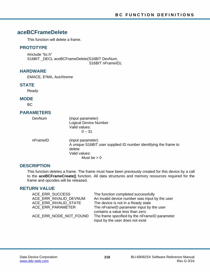
B C F U N C T I O N D E F I N I T I O N S
Data Device Corporation BU-69092SX Software Reference Manual www.ddc-web.com Rev G-3/16
218
aceBCFrameDelete This function will delete a frame.
PROTOTYPE #include “bc.h” S16BIT _DECL aceBCFrameDelete(S16BIT DevNum, S16BIT nFrameID);
HARDWARE EMACE, E²MA, AceXtreme
STATE Ready
MODE BC
PARAMETERS DevNum (input parameter) Logical Device Number Valid values: 0 – 31 nFrameID (input parameter) A unique S16BIT user supplied ID number identifying the frame to delete Valid values: Must be > 0
DESCRIPTION This function deletes a frame. The frame must have been previously created for this device by a call to the aceBCFrameCreate() function. All data structures and memory resources required for the frame and opcodes will be released.
RETURN VALUE ACE_ERR_SUCCESS The function completed successfully ACE_ERR_INVALID_DEVNUM An invalid device number was input by the user ACE_ERR_INVALID_STATE The device is not in a Ready state ACE_ERR_PARAMETER The nFrameID parameter input by the user
contains a value less than zero ACE_ERR_NODE_NOT_FOUND The frame specified by the nFrameID parameter
input by the user does not exist

B C F U N C T I O N D E F I N I T I O N S
Data Device Corporation BU-69092SX Software Reference Manual www.ddc-web.com Rev G-3/16
219
aceBCFrameDelete (continued) EXAMPLE
S16BIT DevNum = 0; S16BIT nResult = 0; S16BIT MNR1 = 1; U16BIT aOpCodes[1]; // create a minor frame aOpCodes[0] = OP1; nResult = aceBCFrameCreate(DevNum, MNR1, ACE_FRAME_MINOR, aOpCodes, 1, 0, 0); nResult = aceBCFrameDelete(DevNum, MNR1); if(nResult < 0) { printf(“Error in aceBCFrameDelete() function \n”); PrintOutError(nResult); return; }
SEE ALSO aceBCFrameCreate()

B C F U N C T I O N D E F I N I T I O N S
Data Device Corporation BU-69092SX Software Reference Manual www.ddc-web.com Rev G-3/16
220
aceBCFrmToHBuf This function triggers the movement of all available messages and data to the message and host buffer.
PROTOTYPE #include “bc.h” S16BIT _DECL aceBCFrmToHBuf(S16BIT DevNum);
HARDWARE EMACE, E²MA, AceXtreme
STATE Ready, Run
MODE BC
PARAMETERS DevNum (input parameter) Logical Device Number Valid values: 0 – 31
DESCRIPTION This function reads the latest messages from the minor frame and writes them out to a Host Buffer provided by the user. The routine will determine which minor frame needs servicing, and handle the transfer. The host buffer will be created using a SDK routine, and then linked to the device. This routine will retrieve the buffer from the device structure, so the only parameter required is the device number. The AceXtreme C SDK contains an internal Interrupt Service Routine that will get triggered if a time tag rollover has occurred when running in bus controller mode or if the end of a minor frame has been reached. The end of minor frame interrupt can be disabled in the aceBCFrameCreate() function. The internal Interrupt Service Routine will call the aceBCFrmToHBuf() function. The aceBCFrmToHBuf() function is used to read all messages from a frame ID to the BC host buffer. This function can be called by the user in BC mode or can be left as an operation performed by the AceXtreme C SDK to reliably transfer data to the host buffer. DDC recommends that the user not call the aceBCFrmToHBuf() function and allow the SDK to internally generate interrupts and transfer data to the host buffer by calling the aceBCFrmToHBuf() function. This function is made available to the advanced user that would like to transfer data to the host buffer more often and is aware of the internal mechanisms that the AceXtreme C SDK is performing or for systems where interrupts are not present.

B C F U N C T I O N D E F I N I T I O N S
Data Device Corporation BU-69092SX Software Reference Manual www.ddc-web.com Rev G-3/16
221
aceBCFrmToHBuf (continued) Each call to aceBCFrmToHBuf() contains an internal function that is used to read all entries currently on the hardware General Purpose Queue to the internal GPQ buffers. This transfer is done inside of a critical section. During this read, all entries are parsed into their correct buffer (User or Lib). Once an entry is read from the hardware General Purpose Queue it is taken off of the queue.
Note: If no buffer is created and attached to the device, this routine will still return with the ACE_ERR_SUCCESS value.
RETURN VALUE ACE_ERR_SUCCESS The function completed successfully ACE_ERR_INVALID_DEVNUM An invalid device number was input by the user ACE_ERR_INVALID_STATE The device is not in a Ready or Run state
EXAMPLE DevNum = 0; // Create and install host buffer aceBCInstallHBuf(DevNum,8*1024); nResult = aceBCFrmToHBuf(DevNum); if(nResult < 0) { printf(“Error in aceBCFrmToHBuf() function \n”); PrintOutError(nResult); return; }
SEE ALSO aceBCFrmToHBuf32() aceBCInstallHBuf()

B C F U N C T I O N D E F I N I T I O N S
Data Device Corporation BU-69092SX Software Reference Manual www.ddc-web.com Rev G-3/16
222
aceBCFrmToHBuf32 This function triggers movement of all available messages and data to the message and host buffer.
PROTOTYPE #include “bc.h” S16BIT _DECL aceBCFrmToHBuf32(S16BIT DevNum);
STATE Ready, Run
MODE BC
PARAMETERS DevNum (input parameter) Logical Device Number Valid values: 0 – 31
DESCRIPTION This function reads the latest messages from the minor frame and writes them out to a Host Buffer provided by the user. The routine will determine which minor frame needs servicing, and handle the transfer. The host buffer will be created using an SDK routine, and then linked to the device. This routine will retrieve the buffer from the device structure, so the only parameter required is the device number. The AceXtreme C SDK contains an internal Interrupt Service Routine that will get triggered if a time tag rollover has occurred when running in bus controller mode or if the end of a minor frame has been reached. The end of minor frame interrupt can be disabled in the aceBCFrameCreate() function. The internal Interrupt Service Routine will call the aceBCFrmToHBuf32() function for all devices except for the BU-65567/68 PC/104 cards and the BU-65553 cards because these cards are ISA devices that will use the aceBCFrmToHBuf() function to create 16-bit memory accesses. The aceBCFrmToHBuf32() function is used to read all messages from a frame ID to the BC host buffer. This function can be called by the user in BC mode or can be left as an operation performed by the AceXtreme C SDK to reliably transfer data to the host buffer. DDC recommends that the user not call the aceBCFrmToHBuf32() function and allow the SDK to internally generate interrupts and transfer data to the host buffer by calling the aceBCFrmToHBuf32() function. This function is made available to the advanced user that would like to transfer data to the host buffer more often and is aware of the internal mechanisms that the AceXtreme C SDK is performing or for systems where interrupts are not present.

B C F U N C T I O N D E F I N I T I O N S
Data Device Corporation BU-69092SX Software Reference Manual www.ddc-web.com Rev G-3/16
223
aceBCFrmToHBuf32 (continued) Each call to aceBCFrmToHBuf32() contains an internal function that is used to read all entries currently on the hardware General Purpose Queue to the internal GPQ buffers. This transfer is done inside of a critical section. During this read, all entries are parsed into their correct buffer (User or Lib). Once an entry is read from the hardware General Purpose Queue it is taken off of the queue.
Note: If no buffer is created and attached to the device, this routine will still return with the ACE_ERR_SUCCESS value.
RETURN VALUE ACE_ERR_SUCCESS The function completed successfully ACE_ERR_INVALID_DEVNUM An invalid device number was input by the user ACE_ERR_INVALID_STATE The device is not in a Ready or Run state
EXAMPLE DevNum = 0; // Create and install host buffer aceBCInstallHBuf(DevNum,8*1024); nResult = aceBCFrmToHBuf32(DevNum); if(nResult < 0) { printf(“Error in aceBCFrmToHBuf32() function \n”); PrintOutError(nResult); return; }
SEE ALSO aceBCFrmToHBuf() aceBCInstallHBuf()

B C F U N C T I O N D E F I N I T I O N S
Data Device Corporation BU-69092SX Software Reference Manual www.ddc-web.com Rev G-3/16
224
aceBCGetAsyncCount This function returns the current number of asynchronous messages in the queue.
PROTOTYPE #include “bc.h” S16BIT _DECL aceBCGetAsyncCount(S16BIT DevNum);
HARDWARE EMACE, E²MA, AceXtreme
STATE Ready
MODE BC
PARAMETERS DevNum (input parameter) Logical Device Number Valid values: 0 – 31
DESCRIPTION This function will retrieve the number of asynchronous messages remaining on the asynchronous message queue.
RETURN VALUE Value >= 0 Number of messages on Queue ACE_ERR_INVALID_DEVNUM An invalid device number was input by the user ACE_ERR_INVALID_MODE The mode of operation selected is invalid ACE_ERR_NOT_ASYNC_MODE Asynchronous option not enabled.
EXAMPLE S16BIT DevNum = 0; S16BIT nResult = 0; /* initialize the device, create and add async messages to queue. */ nResult = aceBCGetAsyncCount(DevNum); if(nResult < 0) { printf(“Error in aceBCGetAsyncCount() function \n”); PrintOutError(nResult); return; }

B C F U N C T I O N D E F I N I T I O N S
Data Device Corporation BU-69092SX Software Reference Manual www.ddc-web.com Rev G-3/16
225
aceBCGetAsyncCount (continued) SEE ALSO
aceBCSendAsyncMsgHP() aceBCSendAsyncMsgLP()

B C F U N C T I O N D E F I N I T I O N S
Data Device Corporation BU-69092SX Software Reference Manual www.ddc-web.com Rev G-3/16
226
aceBCGetConditionCode This function allows the user to read the current state of the desired condition from the BC Condition Code register.
PROTOTYPE #include “bc.h” S16BIT _DECL aceBCGetConditionCode(S16BIT DevNum, U16BIT wConditionCode, U16BIT *pCurrentState);
HARDWARE EMACE, E²MA, AceXtreme
STATE Run
MODE BC
PARAMETERS DevNum (input parameter) Logical Device Number Valid values: 0 – 31 wConditionCode (input parameter) Condition code for which the current state is desired to be read. Valid values: ACE_CND_LT_GT This is the result of a previous “Compare” Opcode. Meaning of the *pCurrentState value: 0 = Greater Than or Equal To 1 = Less Than ACE_CND_EQ_NE This is the result of a previous “Compare” Opcode. Meaning of the *pCurrentState value: 0 = Not Equal To 1 = Equal To

B C F U N C T I O N D E F I N I T I O N S
Data Device Corporation BU-69092SX Software Reference Manual www.ddc-web.com Rev G-3/16
227
aceBCGetConditionCode (continued) ACE_CND_GPF0 ACE_CND_GPF1 ACE_CND_GPF2 ACE_CND_GPF3 ACE_CND_GPF4 ACE_CND_GPF5 ACE_CND_GPF6 ACE_CND_GPF7 ACE_CND_GPF8* ACE_CND_GPF9* ACE_CND_GPF10* ACE_CND_GPF11* ACE_CND_GPF12* ACE_CND_GPF13* ACE_CND_GPF14* ACE_CND_GPF15* These parameters individually check the general purpose flag bits
0-7. Note: * Only supported by AceXtreme and E²MA Devices. ACE_CND_NORES This is the response state of the previous message. Meaning of the *pCurrentState value: 0 = No error
1 = An RT has not responded, or responded later than the BC No Response Timeout
ACE_CND_FMT_ERR This is the format error state of the previous message. Meaning of the *pCurrentState value: 0 = No Error
1 = there were one or more violations of the 1553 message validation criteria (sync, encoding, parity, bit count, word count, etc.), or the status word received from a responding RT contained an incorrect RT address field.
ACE_CND_GD_DATA This is the state of the data block transfer of the previous message.
This is only used for RT-to-BC, RT-to-RT, and Mode-Code-with-transmit-data messages. This bit is not to be used to interpret other message types.
Meaning of the *pCurrentState value: 0 = The data transmitted by the RT was invalid 1 = Good data transmission by the RT.

B C F U N C T I O N D E F I N I T I O N S
Data Device Corporation BU-69092SX Software Reference Manual www.ddc-web.com Rev G-3/16
228
aceBCGetConditionCode (continued) ACE_CND_MSKED_STS This is the Masked Status Set condition. This occurs if the RT
Status Word bits (Message Error, Service Request, Subsystem Flag, the Reserved bits, and Terminal Flag) are set, AND the Status Mask bits in the BC Control Word (BCW) have been set to enabled.
Meaning of the *pCurrentState value: 0 = Masked Status is not set 1 = Masked Status is set ACE_CND_BAD_MSG This indicates the summary error state of the previous message. Meaning of the *pCurrentState value: 0 = No error
1 = One of these errors occurred: format error, loop test fail, or no response error
ACE_CND_RETRY This is the retry status of the previous message: 0 = No retry 1 = 1 retry 2 = Not used 3 = 2 retries ACE_CND_ALWAYS Meaning of the *pCurrentState value: 0 = the BC is not running 1 = the BC is running PCurrentState The state of the desired condition from the BC Condition Code
Register. Valid values: 0 or 1 for all conditions, except for 0, 1, 2, or 3 for ACE_CND_RETRY
DESCRIPTION This function allows the user to obtain the state of a single condition from the BC Condition Code register by specifying the desired Condition Code in the wConditionCode input parameter. The device must be in BC mode for this function to operate. Note that for message-related Condition Codes (such as No Response or Retry) the function returns, via the *pCurrentState parameter, the current running state of the BC Condition Code register. If the BC Opcode engine has completed executing a message (EOM) and is currently idle, then the value retrieved will represent the state of the previous message. On the other hand, if the BC Opcode engine has started executing a new message (SOM), then the value returned could be zeroed, and will not represent the state of the previous message.

B C F U N C T I O N D E F I N I T I O N S
Data Device Corporation BU-69092SX Software Reference Manual www.ddc-web.com Rev G-3/16
229
aceBCGetConditionCode (continued) To guarantee the retrieval of the message-related Condition Codes, it is recommended that the latched condition bits be retrieved from the RT Status Word or the BC Block Status Word that is retrieved when using the message retrieval API in the BC, such as aceBCGetMsgFromIDDecoded(). For non-message-related Condition Codes (such as Less Than or GPF2), this function is the correct method for retrieving the state.
RETURN VALUE ACE_ERR_SUCCESS The function completed successfully ACE_ERR_INVALID_DEVNUM An invalid device number was input by the user ACE_ERR_INVALID_STATE The device is not in a Run state and/or the BC is not enabled ACE_ERR_PARAMETER The wConditionCode parameter contains an invalid value
or the pCurrentState parameter is NULL
EXAMPLE DevNum = 0; U16BIT pCurrentState; nResult = aceBCGetConditionCode(DevNum, ACE_CND_NORES, &pCurrentState); if(nResult < 0) { printf(“Error in aceBCGetConditionCode() function \n”); PrintOutError(nResult); return; }
SEE ALSO None

B C F U N C T I O N D E F I N I T I O N S
Data Device Corporation BU-69092SX Software Reference Manual www.ddc-web.com Rev G-3/16
230
aceBCGetGPQMetric This function allows the user to get metrics for the GPQ.
PROTOTYPE #include “bc.h” S16BIT _DECL aceBCGetGPQMetric(S16BIT DevNum, GPQMETRIC *pGPQMetric, U16BIT bReset);
HARDWARE EMACE, E²MA, AceXtreme
STATE Ready, Run
MODE BC
PARAMETERS DevNum (input parameter) Logical Device Number Valid values: 0 – 31 pMetric (output parameter)
Pointer to a GPQMETRIC structure to be filled in with metrics. The GPQMETRIC structure contains the following members: dwLost, wPctFull, and wHighPct. The dwLost member parameter contains the total number of messages lost in the GPQ. The wPctFull member parameter contains the current percentage of the GPQ being used at one snapshot in time. The wHighPct member parameter contains the highest percentage of the GPQ used over an extended period of time.
bReset (input parameter)
This will specify if the metrics should be reset at this time to start clean. Valid values: FALSE (0) Do not reset the metrics TRUE (1) Reset metrics

B C F U N C T I O N D E F I N I T I O N S
Data Device Corporation BU-69092SX Software Reference Manual www.ddc-web.com Rev G-3/16
231
aceBCGetGPQMetric (continued) DESCRIPTION
This function returns performance information about the General Purpose Queue. The built in metrics can report the total number of messages lost in the General Purpose Queue, the current percentage of the General Purpose Queue that is used, and the highest percentage of the General Purpose Queue used over an extended period of time.
RETURN VALUE ACE_ERR_SUCCESS The function completed successfully ACE_ERR_INVALID_DEVNUM An invalid device number was input to this function ACE_ERR_INVALID_STATE The device is not in a Ready or Run state and the function
could not be completed ACE_ERR_PARAMETER The pMetric pointer is Null. ACE_ERR_METRICS_NOT_ENA Metrics are not enabled and should be set by calling the
aceSetMetrics() function
EXAMPLE //This will get performance metrics for the GPQ
S16BIT DevNum = 0; S16BIT nResult = 0; GPQMETRIC sGPQMetric; nResult = aceBCGetGPQMetric(DevNum, &sGPQMetric, 0); if(nResult < 0) { printf(“Error in aceBCGetGPQMetric() function \n”); PrintOutError(nResult); return; } else { printf(“GPQ pct full: %d \n”, sGPQMetric.wPctFull); printf(“GPQ highest pct full: %d \n”, sGPQMetric.wHighPct); printf(“GPQ lost messages: %d \n”, sGPQMetric.dwLost); }
SEE ALSO aceSetMetrics() aceBCGetHBufMetric() aceRTGetHBufMetric() aceRTGetStkMetric() aceMTGetHBufMetric() aceMTGetStkMetric()

B C F U N C T I O N D E F I N I T I O N S
Data Device Corporation BU-69092SX Software Reference Manual www.ddc-web.com Rev G-3/16
232
aceBCGetHBufMetric This function returns performance information about the host buffer.
PROTOTYPE #include “bc.h” S16BIT _DECL aceBCGetHBufMetric (S16BIT DevNum, BUFMETRIC *pMetric, U16BIT bReset);
HARDWARE EMACE, E²MA, AceXtreme
STATE Ready, Run
MODE BC
PARAMETERS DevNum (input parameter) Logical Device Number Valid values:
0 – 31
pMetric (output parameter) Pointer to an HBUFMETRIC structure to be filled in with metrics.
The HBUFMETRIC structure contains the following members: dwCount, dwLost, dwPctFull, and dwHighPct. The dwCount member parameter contains the total number of messages in the host buffer. The dwLost member parameter contains the total number of messages lost in the host buffer. The dwPctFull member parameter contains the percentage of the host buffer used at one snapshot in time. The dwHighPct member parameter contains the highest percentage of the host buffer used over an extended period of time.
Member Variable Name Definition dwCount The number of messages in the host buffer
dwLost The total number of messages lost since the host buffer was installed
dwPctFull The current percentage of host buffer used
dwHighPct The highest percentage of the host buffer used since the host buffer was installed or metrics were reset
B C F U N C T I O N D E F I N I T I O N S
Data Device Corporation BU-69092SX Software Reference Manual www.ddc-web.com Rev G-3/16
233
aceBCGetHBufMetric (continued) bReset (input parameter)
This will specify if the highest percentage value should be reset after this function returns
Valid values: FALSE (0) Do not reset the highest percentage value TRUE (1) Reset the highest percentage value
DESCRIPTION This function returns performance information about the BC Host Buffer. Built-in test metrics can report the number of messages in the host buffer, the total number of messages lost since the host buffer was installed, the current percentage of the host buffer that is used, and the highest percentage of the host buffer used since it was installed.
RETURN VALUE ACE_ERR_SUCCESS The function completed successfully ACE_ERR_INVALID_DEVNUM An invalid device number was input by the user ACE_ERR_INVALID_STATE The device is not in a Ready or Run state ACE_ERR_INVALID_MODE The device is not in BC mode ACE_ERR_PARAMETER The pMetric pointer input by the user is NULL ACE_ERR_METRICS_NOT_ENA Metrics are not enabled and should be set by
calling the aceSetMetrics() function
EXAMPLE S16BIT DevNum = 0; S16BIT nResult = 0; S16BIT bReset = 1; HBUFMETRIC *pMetric; nResult = aceBCGetHBufMetric(DevNum, pMetric, bReset) if(nResult < 0) { printf(“Error in aceBCGetHBufMetric() function \n”); PrintOutError(nResult); return; }
SEE ALSO aceSetMetrics() aceBCGetGPQMetric() aceRTGetHBufMetric() aceRTGetStkMetric() aceMTGetHBufMetric() aceMTGetStkMetric()

B C F U N C T I O N D E F I N I T I O N S
Data Device Corporation BU-69092SX Software Reference Manual www.ddc-web.com Rev G-3/16
234
aceBCGetHBufMsgCount This function returns the number of msgs in the host buffer.
PROTOTYPE #include “bc.h” S16BIT _DECL aceBCGetHBufMsgCount(S16BIT DevNum);
HARDWARE EMACE, E²MA, AceXtreme
STATE Ready, Run
MODE BC
PARAMETERS DevNum (input parameter) Logical Device Number Valid values:
0 – 31
DESCRIPTION This function returns the number of msgs in the host buffer.
RETURN VALUE ACE_ERR_INVALID_DEVNUM An invalid device number was input by the user ACE_ERR_INVALID_STATE The device is not in a Ready or Run state ACE_ERR_INVALID_MODE The device is not in BC mode number >= 0 The number of messages that are currently in the
host buffer
EXAMPLE S16BIT DevNum = 0; S16BIT dwCount = 0; dwCount = aceBCGetHBufMsgCount(DevNum); if(dwCount < 0) { printf(“Error in aceBCGetHBufMsgCount() function \n”); PrintOutError(dwCount); return; }
SEE ALSO None
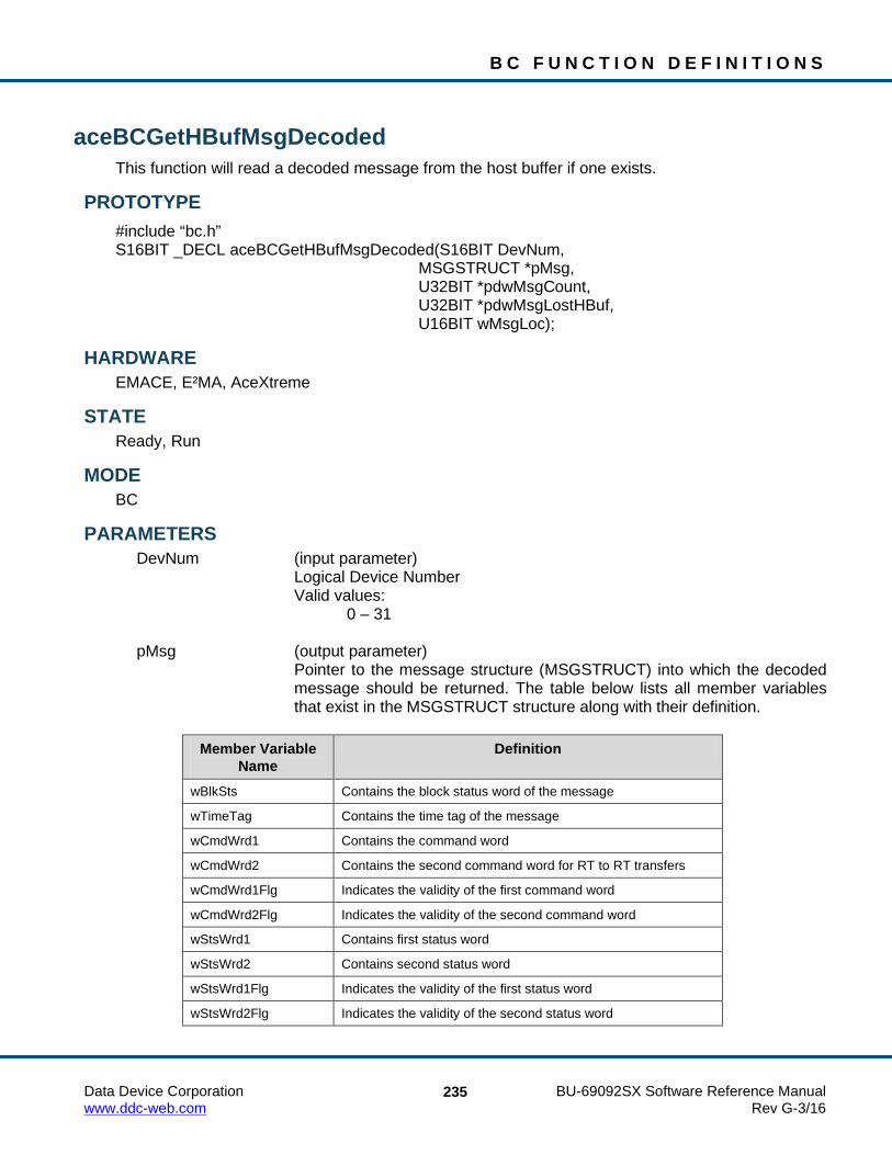
B C F U N C T I O N D E F I N I T I O N S
Data Device Corporation BU-69092SX Software Reference Manual www.ddc-web.com Rev G-3/16
235
aceBCGetHBufMsgDecoded This function will read a decoded message from the host buffer if one exists.
PROTOTYPE #include “bc.h” S16BIT _DECL aceBCGetHBufMsgDecoded(S16BIT DevNum, MSGSTRUCT *pMsg, U32BIT *pdwMsgCount, U32BIT *pdwMsgLostHBuf, U16BIT wMsgLoc);
HARDWARE EMACE, E²MA, AceXtreme
STATE Ready, Run
MODE BC
PARAMETERS DevNum (input parameter) Logical Device Number Valid values: 0 – 31 pMsg (output parameter)
Pointer to the message structure (MSGSTRUCT) into which the decoded message should be returned. The table below lists all member variables that exist in the MSGSTRUCT structure along with their definition.
Member Variable
Name Definition
wBlkSts Contains the block status word of the message
wTimeTag Contains the time tag of the message
wCmdWrd1 Contains the command word
wCmdWrd2 Contains the second command word for RT to RT transfers
wCmdWrd1Flg Indicates the validity of the first command word
wCmdWrd2Flg Indicates the validity of the second command word
wStsWrd1 Contains first status word
wStsWrd2 Contains second status word
wStsWrd1Flg Indicates the validity of the first status word
wStsWrd2Flg Indicates the validity of the second status word

B C F U N C T I O N D E F I N I T I O N S
Data Device Corporation BU-69092SX Software Reference Manual www.ddc-web.com Rev G-3/16
236
aceBCGetHBufMsgDecoded (continued)
Member Variable Name
Definition
wWordCount Contains the number of valid data words
aDataWrds[32] An array that will contain the data words
wBCCtrlWrd Contains the BC Control Word for BC mode messages only
wBCGapTime Contains the message gap time only for BC
wBCLoopBack1 Contains the first looped back word for BC mode messages only
wTimeTag2 Not used in BC Mode. BC Time Tag is only 16 bits
wBCLoopBack1Flg Indicates validity of first loop back word for BC mode message only
wTimeTag3 Not used in BC Mode. BC Time Tag is only 16 bits
pdwMsgCount (output parameter)
Pointer to the variable that will contain the message count returned Valid values: 1 – One message was returned 0 – No messages were returned pdwMsgLostHBuf (output parameter) The number of times that a buffer full condition was encountered wMsgLoc (input parameter)
Defined macro describing the location the desired message should be read from. Next indicates the next unread message on the host buffer. Latest will read the latest message just processed by the BC. All messages between the last read message and the latest message will be skipped. Purge indicates the message will be taken off of the host buffer. Npurge indicates that the message will remain on the host buffer.
Valid values: ACE_BC_MSGLOC_NEXT_PURGE Retrieves the next message and takes it off of the host buffer ACE_BC_MSGLOC_NEXT_NPURGE Retrieves the next message and leaves it on the host buffer ACE_BC_MSGLOC_LATEST_PURGE Retrieves the current message and takes it off of the host buffer ACE_BC_MSGLOC_LATEST_NPURGE Retrieves the current message and leaves it on the host buffer

B C F U N C T I O N D E F I N I T I O N S
Data Device Corporation BU-69092SX Software Reference Manual www.ddc-web.com Rev G-3/16
237
aceBCGetHBufMsgDecoded (continued) DESCRIPTION
This function reads a decoded message from the host buffer if it is present. While the BC is running, messages can be moved from the hardware memory to a host buffer in raw BC format. These messages may be read and decoded into a user buffer using this routine. The decoded messages are in the form of the MSGSTRUCT structure, which allows the user to easily access the relevant part of the message in an easy to read format.
Note: If no buffer is created and attached to the device, the function will still return with the ACE_ERR_SUCCESS code.
RETURN VALUE ACE_ERR_SUCCESS The function completed successfully ACE_ERR_INVALID_DEVNUM An invalid device number was input by the user ACE_ERR_INVALID_STATE The device is not in a Ready or Run state ACE_ERR_PARAMETER The wMsgLoc parameter contains a value greater
than three or the pdwMsgLostHBuf parameter is NULL
EXAMPLE DevNum = 0; MSGSTRUCT pMsg; U32BIT pdwMsgCount, pdwMsgLostHBuf; U16BIT wMsgLoc; // Create and install host buffer aceBCInstallHBuf(DevNum,8*1024); // move data from stack to host buffer aceBCFrmToHBuf(DevNum); // read the next unread message on stack and then purge its existence // from the stack wMsgLoc = ACE_BC_MSGLOC_NEXT_PURGE; nResult = aceBCGetHBufMsgDecoded(DevNum, &pMsg, &pdwMsgCount, &pdwMsgLostHBuf, wMsgLoc) if(nResult < 0) { printf(“Error in aceBCGetHBufMsgDecoded() function \n”); PrintOutError(nResult); return; }
SEE ALSO aceBCInstallHBuf() aceBCFrmToHBuf() aceBCGetHBufMsgsRaw()

B C F U N C T I O N D E F I N I T I O N S
Data Device Corporation BU-69092SX Software Reference Manual www.ddc-web.com Rev G-3/16
238
aceBCGetHBufMsgsRaw This function will read raw messages from the host buffer if they exist.
PROTOTYPE #include “bc.h” S16BIT _DECL aceBCGetHBufMsgsRaw(S16BIT DevNum, U16BIT *pBuffer, U16BIT wBufferSize, U32BIT *pdwMsgCount, U32BIT *pdwMsgLostHBuf);
HARDWARE EMACE, E²MA, AceXtreme
STATE Ready, Run
MODE BC
PARAMETERS DevNum (input parameter) Logical Device Number Valid values: 0 – 31 pBuffer (output parameter) Pointer to a word buffer for message information wBufferSize (input parameter) Size of buffer in words pdwMsgCount (output parameter) Pointer to a double word buffer to be filled with the message count pdwMsgLostHBuf (output parameter) Pointer to a double word buffer to be filled with the number of messages lost
DESCRIPTION This function reads as many messages as possible off of the host buffer. If no errors occur the amount of messages will be returned. The limiting factor when copying messages to the local buffer is the local buffer size and the number of messages available on the host buffer.

B C F U N C T I O N D E F I N I T I O N S
Data Device Corporation BU-69092SX Software Reference Manual www.ddc-web.com Rev G-3/16
239
aceBCGetHBufMsgsRaw (continued)
Note: Each message is a fixed length of ACE_MSGSIZE_BC (42) words.
Note: If no buffer is created and attached to the device, the routine will still return with the ACE_ERR_SUCCESS code.
RETURN VALUE ACE_ERR_SUCCESS The function completed successfully or no host
buffer exists ACE_ERR_INVALID_DEVNUM An invalid device number was input by the user ACE_ERR_INVALID_STATE The device is not in a Ready or Run state ACE_ERR_PARAMETER An invalid parameter was input by the user
EXAMPLE DevNum = 0; MSGSTRUCT pMsg; U32BIT pdwMsgCount, pdwMsgLostHBuf; U16BIT pBuffer[1024], wBufferSize = 1024; // Create and install host buffer aceBCInstallHBuf(DevNum,8*1024); // move data from stack to host buffer aceBCFrmToHBuf(DevNum); // read the next 1024 words from the host buffer nResult = aceBCGetHBufMsgsRaw(DevNum, &pBuffer, BufferSize, &pdwMsgCount, &pdwMsgLostHBuf); if(nResult < 0) { printf(“Error in aceBCGetHBufMsgsRaw() function \n”); PrintOutError(nResult); return; }
SEE ALSO aceBCInstallHBuf() aceBCFrmToHBuf() aceBCGetHBufMsgDecoded()

B C F U N C T I O N D E F I N I T I O N S
Data Device Corporation BU-69092SX Software Reference Manual www.ddc-web.com Rev G-3/16
240
aceBCGetMsgFromIDDecoded This function will read a message on the stack based on the message ID.
PROTOTYPE #include “bc.h” S16BIT _DECL aceBCGetMsgFromIDDecoded(S16BIT DevNum, S16BIT nMsgBlkID, MSGSTRUCT *pMsg, U16BIT bPurge);
HARDWARE EMACE, E²MA, AceXtreme
STATE Ready, Run
MODE BC
PARAMETERS DevNum (input parameter) Logical Device Number Valid values: 0 – 31 nMsgBlkID (input parameter) The message ID that will be read and decoded Valid values: A previously defined message block ID >=0 pMsg Pointer to a MSGSTRUCT to be filled with the decoded message.
The table below lists all member variables that exist in the MSGSTRUCT structure along with their definition.
Member Variable
Name Definition
wBlkSts Contains the block status word of the message
wTimeTag Contains the time tag of the message
wCmdWrd1 Contains the command word
wCmdWrd2 Contains the second command word for RT to RT transfers
wCmdWrd1Flg Indicates the validity of the first command word
wCmdWrd2Flg Indicates the validity of the second command word
wStsWrd1 Contains first status word
wStsWrd2 Contains second status word

B C F U N C T I O N D E F I N I T I O N S
Data Device Corporation BU-69092SX Software Reference Manual www.ddc-web.com Rev G-3/16
241
aceBCGetMsgFromIDDecoded (continued) Member Variable
Name Definition
wStsWrd1Flg Indicates the validity of the first status word
wStsWrd2Flg Indicates the validity of the second status word
wWordCount Contains the number of valid data words
aDataWrds[32] An array that will contain the data words
wBCCtrlWrd Contains the BC Control Word for BC mode messages only
wBCGapTime Contains the message gap time only for BC
wBCLoopBack1 Contains the first looped back word for BC mode messages only
wTimeTag2 Not used in BC Mode. BC Time Tag is only 16 bits
wBCLoopBack1Flg Indicates validity of first loop back word for BC mode message only
wTimeTag3 Not used in BC Mode. BC Time Tag is only 16 bits
bPurge Indicates that the message should be purged after reading Valid values: TRUE FALSE
DESCRIPTION This function reads either the next unread message or the latest msg received on the stack based on the message block ID input by the user. The function then decodes the message by placing all the info into a MSGSTRUCT structure pointed to by the pMsg parameter by calling the aceBCDecodeRawMsg() function.
RETURN VALUE ACE_ERR_INVALID_DEVNUM An invalid device number was input by the user ACE_ERR_INVALID_STATE The device is not in a Ready or Run state ACE_ERR_MSGSTRUCT The pMsg pointer to the MSGSTRUCT structure
contains a NULL value NUMBER 1 = Valid Message
0 = No New Message

B C F U N C T I O N D E F I N I T I O N S
Data Device Corporation BU-69092SX Software Reference Manual www.ddc-web.com Rev G-3/16
242
aceBCGetMsgFromIDDecoded (continued) EXAMPLE
S16BIT DevNum = 0; MSGSTRUCT pMsg; S16BIT nMsgBlkID = 100; nResult = aceBCGetMsgFromIDDecoded(DevNum, nMsgBlkID, &pMsg, TRUE); if(nResult < 0) { printf(“Error in aceBCGetMsgFromIDDecoded() function \n”); PrintOutError(nResult); return; }
SEE ALSO aceBCFrmToHBuf() aceBCGetHBufMsgDecoded()

B C F U N C T I O N D E F I N I T I O N S
Data Device Corporation BU-69092SX Software Reference Manual www.ddc-web.com Rev G-3/16
243
aceBCGetMsgFromIDRaw This function will read a raw message based on the message block ID.
PROTOTYPE #include “bc.h” S16BIT _DECL aceBCGetMsgFromIDRaw(S16BIT DevNum, S16BIT nMsgBlkID, U16BIT *pBuffer, U16BIT bPurge);
HARDWARE EMACE, E²MA, AceXtreme
STATE Ready, Run
MODE BC
PARAMETERS DevNum (input parameter) Logical Device Number Valid values: 0 – 31 nMsgBlkID (input parameter) The message ID that will be read and decoded pBuffer (output parameter) Pointer to a buffer that will contain the raw message from the BC bPurge (input parameter) Indicates that the message should be purged after reading Valid values: TRUE FALSE
DESCRIPTION This function reads a message given its ID into the given buffer. The message is written in its raw format as read from the BC message data block structures.
Note: Buffer must be at least ACE_MSGSIZE_BC words long.

B C F U N C T I O N D E F I N I T I O N S
Data Device Corporation BU-69092SX Software Reference Manual www.ddc-web.com Rev G-3/16
244
aceBCGetMsgFromIDRaw (continued) RETURN VALUE
0 No message read 1 One message was read ACE_ERR_INVALID_DEVNUM An invalid device number was input by the user ACE_ERR_INVALID_STATE The device is not in a Ready or Run state ACE_ERR_INVALID_BUF The pBuffer pointer contains a NULL value
EXAMPLE S16BIT DevNum = 0; S16BIT nMsgBlkID = 15; U16BIT pBuffer[ACE_MSGSIZE_BC]; nResult = aceBCGetMsgFromIDRaw(DevNum, nMsgBlkID, &pBuffer, TRUE); if (nResult < 0) { printf(“Error in aceBCGetMsgFromIDDecoded() function \n”); PrintOutError(nResult); return; }
SEE ALSO aceBCFrmToHBuf() aceBCGetHBufMsgDecoded()

B C F U N C T I O N D E F I N I T I O N S
Data Device Corporation BU-69092SX Software Reference Manual www.ddc-web.com Rev G-3/16
245
aceBCGetMsgHdrFromIDRaw This function reads a message header only given its ID into the given buffer.
PROTOTYPE #include “bc.h” S16BIT _DECL aceBCGetMsgHdrFromIDRaw(S16BIT DevNum, S16BIT nMsgBlkID, U16BIT *pBuffer, U16BIT bPurge);
HARDWARE EMACE, E²MA, AceXtreme
STATE Ready, Run
MODE BC
PARAMETERS DevNum (input parameter) Logical Device Number Valid values: 0 – 31 nMsgBlkID (input parameter) Unique ID for the message block to read (> 0) pBuffer (output parameter) Pointer to storage for the message header (!= NULL) bPurge (input parameter) Indicates that the message should be purged after reading Valid values: TRUE = purge FALSE = do not purge
DESCRIPTION This function reads a message header only given its ID into the given buffer. The message is written in its raw format.

B C F U N C T I O N D E F I N I T I O N S
Data Device Corporation BU-69092SX Software Reference Manual www.ddc-web.com Rev G-3/16
246
aceBCGetMsgHdrFromIDRaw (continued) RETURN VALUE
0 No message read 1 One message was read ACE_ERR_INVALID_DEVNUM An invalid device number was input by the user ACE_ERR_INVALID_STATE The device is not in a Ready or Run state ACE_ERR_INVALID MODE The device is not in BC mode ACE_ERR_INVALID_BUF The pBuffer pointer contains a NULL value ACE_ERR_PARAMETER The nMsgBlkID parameter is < 0
EXAMPLE S16BIT DevNum = 0; S16BIT nMsgBlkID = 15; U16BIT pBuffer[ACE_MSGSIZE_BC]; nResult = aceBCGetMsgHdrFromIDRaw(DevNum, nMsgBlkID, &pBuffer, TRUE); if (nResult < 0) { printf(“Error in aceBCGetMsgFromIDDecoded() function \n”); PrintOutError(nResult); return; }
SEE ALSO aceBCGetHBufMsgDecoded()

B C F U N C T I O N D E F I N I T I O N S
Data Device Corporation BU-69092SX Software Reference Manual www.ddc-web.com Rev G-3/16
247
aceBCGetStatus This function returns whether the BC is busy sending messages.
PROTOTYPE #include “bc.h” S16BIT _DECL aceBCGetStatus(S16BIT DevNum, U16BIT *wStatus);
HARDWARE EMACE, E²MA, AceXtreme
STATE Ready, Run
MODE BC
PARAMETERS DevNum (input parameter) Logical Device Number Valid values: 0 – 31 wStatus (output parameter) Pointer to the location to return BC status ACE_BC_BUSY ACE_BC_IDLE
DESCRIPTION This function returns whether the BC is busy sending messages.
RETURN VALUE ACE_ERR_SUCCESS The function completed successfully ACE_ERR_INVALID_DEVNUM An invalid device number was input by the user ACE_ERR_INVALID_STATE The device is not in a Ready or Run state

B C F U N C T I O N D E F I N I T I O N S
Data Device Corporation BU-69092SX Software Reference Manual www.ddc-web.com Rev G-3/16
248
aceBCGetStatus (continued) EXAMPLE
S16BIT DevNum = 0; U16BIT wStatus; nResult = aceBCGetStatus(DevNum, &wStatus); { printf(“Error in aceBCGetStatus() function \n”); PrintOutError(nResult); return; }
SEE ALSO None

B C F U N C T I O N D E F I N I T I O N S
Data Device Corporation BU-69092SX Software Reference Manual www.ddc-web.com Rev G-3/16
249
aceBCGPQGetCount This function will return the number of entries currently in the general purpose queue.
PROTOTYPE #include “bc.h” S16BIT _DECL aceBCGPQGetCount(S16BIT DevNum);
HARDWARE EMACE, E²MA, AceXtreme
STATE Ready, Run
MODE BC
PARAMETERS DevNum (input parameter) Logical Device Number Valid values: 0 – 31
DESCRIPTION This function returns the number of entries currently in the general purpose queue. Each entry consists of two unsigned 16-bit words. One 16-bit word is a wGPQHeader that contains the information on what the data is. The other 16-bit word is a wGPQData parameter that contains the data for the entry. When the user places an entry on the GPQ, the wGPQHeader entry is the first entry on the queue and can be any value except for 0xFFFF or 0xFFF8. This header value will be a unique identifier for the data that the user will place on the queue. The SDK uses the GPQ internally and will push the 0xFFF8 or 0xFFFF header values onto the queue at the end of each minor frame or major frame respectively in BC mode of operation. NOTE: SDK versions less than or equal to 1.5.4 returned the total number of messages in the GPQ when this function was called. SDK versions greater than or equal to 1.5.5 return the total number of messages in the GPQ input only by the user. You can use Metrics to find out the total number of messages in the host buffer, the total number of messages lost since the host buffer was installed, the current percentage of the host buffer that is used, the highest percentage of the host buffer used since it was installed, the number of messages lost in the GPQ, the current percentage of the GPQ that is used, and the highest percentage of the GPQ used over an extended period of time.

B C F U N C T I O N D E F I N I T I O N S
Data Device Corporation BU-69092SX Software Reference Manual www.ddc-web.com Rev G-3/16
250
aceBCGPQGetCount (continued) RETURN VALUE
ACE_ERR_SUCCESS The function completed successfully or there were no more entries in the general purpose queue
ACE_ERR_INVALID_DEVNUM An invalid device number was input by the user ACE_ERR_INVALID_STATE The device is not in a Ready or Run state
EXAMPLE S16BIT DevNum = 0; S16BIT nResult = 0; nResult = aceBCGPQGetCount(DevNum); printf(“number of entries on the GP Queue = %d \n”, nResult);
SEE ALSO None

B C F U N C T I O N D E F I N I T I O N S
Data Device Corporation BU-69092SX Software Reference Manual www.ddc-web.com Rev G-3/16
251
aceBCGPQRead This function will read the next unread entry off of the general purpose queue.
PROTOTYPE #include “bc.h” S16BIT _DECL aceBCGPQRead(S16BIT DevNum, GPQENTRY* pGPQEntry);
HARDWARE EMACE, E²MA, AceXtreme
STATE Ready, Run
MODE BC
PARAMETERS DevNum (input parameter) Logical Device Number Valid values: 0 – 31 pGPQEntry (output parameter)
A pointer to a GPQENTRY structure, which will contain the entry, read off of the General Purpose queue
DESCRIPTION This function reads off the next unread entry off of the general purpose queue. NOTE: SDK versions less than or equal to 1.5.4 returned all messages in the GPQ when this function was called. SDK versions greater than or equal to 1.5.5 return the messages in the GPQ input only by the user. You can use Metrics to find out the total number of messages in the host buffer, the total number of messages lost since the host buffer was installed, the current percentage of the host buffer that is used, the highest percentage of the host buffer used since it was installed, the number of lost messages in the GPQ, the percentage of the GPQ full, and the highest percentage of the GPQ full since the BC started.

B C F U N C T I O N D E F I N I T I O N S
Data Device Corporation BU-69092SX Software Reference Manual www.ddc-web.com Rev G-3/16
252
aceBCGPQRead (continued) RETURN VALUE
0 No entries were read 1 An entry was read 2 An entry was read with an overrun condition ACE_ERR_INVALID_DEVNUM An invalid device number was input by the user ACE_ERR_INVALID_STATE The device is not in a Ready or Run state ACE_ERR_PARAMETER The pGPQEntry pointer to a GPQENTRY structure
contains a NULL value
EXAMPLE S16BIT DevNum = 0; GPQENTRY pGPQEntry; nResult = aceBCGPQRead(DevNum, &pGPQEntry) if(nResult < 0) { printf(“Error in aceBCGPQRead() function \n”); PrintOutError(nResult); return; } else { switch (nResult) { case 0: //no entries read from GPQ break; case 1: //One entry read from GPQ break; case 2: //entry read with GPQ overrun break; } }
SEE ALSO None

B C F U N C T I O N D E F I N I T I O N S
Data Device Corporation BU-69092SX Software Reference Manual www.ddc-web.com Rev G-3/16
253
aceBCInstallHBuf This function will allocate a host buffer.
PROTOTYPE #include “bc.h” S16BIT _DECL aceBCInstallHBuf(S16BIT DevNum, U32BIT dwHBufSize);
HARDWARE EMACE, E²MA, AceXtreme
STATE Ready
MODE BC
PARAMETERS DevNum (input parameter) Logical Device Number Valid values: 0 – 31 dwHBufSize (input parameter) Size of new buffer in 16-bit words. Valid value: 4K – 5000K 16- bit words
DESCRIPTION This function allocates a host buffer based on the size parameter. For this function to succeed the size must be at least 4K 16-bit words and can not exceed 5000K 16-bit words. This function will enable IRQ conditions so that they may be used. NOTE: The dwHBufSize parameter is in 16-bit words.
RETURN VALUE ACE_ERR_SUCCESS The function completed successfully ACE_ERR_INVALID_DEVNUM An invalid device number was input by the user ACE_ERR_INVALID_STATE The device is not in a Ready state ACE_ERR_INVALID_MODE The device is not in BC mode ACE_ERR_HBUFSIZE The dwHBufSize parameter is less than 4096 (4K) ACE_ERR_HBUF The requested memory could not be allocated for
the host buffer

B C F U N C T I O N D E F I N I T I O N S
Data Device Corporation BU-69092SX Software Reference Manual www.ddc-web.com Rev G-3/16
254
aceBCInstallHBuf (continued) EXAMPLE
S16BIT DevNum = 0; U32BIT dwHBufSize 8192; // 8K words buffer size nResult = aceBCInstallHBuf(DevNum, dwHBufSize) if(nResult < 0) { printf(“Error in aceBCInstallHBuf() function \n”); PrintOutError(nResult); return; }
SEE ALSO None

B C F U N C T I O N D E F I N I T I O N S
Data Device Corporation BU-69092SX Software Reference Manual www.ddc-web.com Rev G-3/16
255
aceBCMsgCreate This function creates a message block to be used inside of frames.
PROTOTYPE #include “bc.h” S16BIT _DECL aceBCMsgCreate(S16BIT DevNum, S16BIT nMsgBlkID, S16BIT nDataBlkID1, U16BIT wBCCtrlWrd1, U16BIT wCmdWrd1_1, U16BIT wCmdWrd1_2, U16BIT wMsgGapTime1, S16BIT nDataBlkID2, U16BIT wBCCtrlWrd2, U16BIT wCmdWrd2_1, U16BIT wCmdWrd2_2, U16BIT wMsgGapTime2, U32BIT dwMsgOptions);
HARDWARE EMACE, E²MA, AceXtreme
STATE Ready
MODE BC
PARAMETERS DevNum (input parameter) Logical Device Number Valid values: 0 – 31 nMsgBlkID (input parameter) Unique ID number for the new msg block Valid values:
≥ 0 nDataBlkID1 (input parameter) Unique ID number of previously created data block Valid values:
A previously created id number > 0

B C F U N C T I O N D E F I N I T I O N S
Data Device Corporation BU-69092SX Software Reference Manual www.ddc-web.com Rev G-3/16
256
aceBCMsgCreate (continued) wBCCtrlWrd1 (input parameter) The BC control word of the msg block Valid values: Bitwise OR'ed combination of the following that will set bits
in the BC Control Word Register at memory location 0x04: ACE_BCCTRL_1553A This parameter will write a 1 to 1553 A/B Select bit 3 to
select 1553A. Applicable only if the Enhanced Mode Enabled bit 15 of Configuration Register # 3 at memory location 0x07 is set to a logic 1 and Expanded BC Control Word bit 12 of Configuration Register # 4 at memory location 0x08 is also programmed to a logic 1.
The Expanded BC Control Word bit can be programmed to a logic
1 by reading the contents of Configuration Register # 4 at memory location 0x08 with the aceRegRead() function and logically OR the value with the CFG4_BC_ENH_CTRL_WORD word. You can then write this value to the register with the aceRegWrite() function.
The Enhanced Mode Enabled bit 15 of Configuration Register # 3
is set to a logic 1 by default when you configure the device for BC, RT, MT, or RTMT mode.
ACE_BCCTRL_EOM_IRQ This parameter will write a 1 to EOM Interrupt Enable bit 4 to result
in an interrupt request at the end of a message if bit 4 of Interrupt Mask Register # 1 at memory location 0x00 is set to a logic 1 by calling the aceSetIrqConditions() function. Applicable only if the Enhanced Mode Enabled bit 15 of Configuration Register # 3 at memory location 0x07 is set to a logic 1 and Expanded BC Control Word bit 12 of Configuration Register # 4 at memory location 0x08 is also programmed to a logic 1.
The Expanded BC Control Word bit can be programmed to a logic
1 by reading the contents of Configuration Register # 4 at memory location 0x08 with the aceRegRead() function and logically OR the value with the CFG4_BC_ENH_CTRL_WORD word. You can then write this value to the register with the aceRegWrite() function.
The Enhanced Mode Enabled bit 15 of Configuration Register # 3
is set to a logic 1 by default when you configure the device for BC, RT, MT, or RTMT mode.

B C F U N C T I O N D E F I N I T I O N S
Data Device Corporation BU-69092SX Software Reference Manual www.ddc-web.com Rev G-3/16
257
aceBCMsgCreate (continued) ACE_BCCTRL_BCST_MSK This parameter will write a 1 to Mask Broadcast bit 5. If Broadcast Mask ENA/XOR* bit 11 of Configuration Register # 4 is
logic 0, then the "expected value" of the Broadcast Command Received bit becomes 1, rather than 0 if this parameter is chosen as an input to this function. That is, a value of logic "0" (rather than logic "1") for the Broadcast Command Received bit in the received RT Status Word will result in a "Status Set" condition.
Broadcast Mask ENA/XOR* bit 11 of Configuration Register # 4 is 0 by default.
If the Enhanced Mode Enabled bit 15 of Configuration Register # 3
at memory location 0x07 is set to a logic 1 and Broadcast Mask ENA/XOR* bit 11 of Configuration Register # 4 at memory location 0x08 is also programmed to a logic 1, and Expanded BC Control Word Enable bit 12 of Configuration Register # 4 is a logic 1, then this parameter will set the Mask Broadcast bit 5 to a logic 1 to be used as a mask bit, rather than performing an "XOR" operation with the Broadcast Received Status Word bit.
The Expanded BC Control Word bit 12 of Configuration Register #
4 must also be programmed to a logic 1. This bit can be programmed to a logic 1 by reading the contents of Configuration Register # 4 at memory location 0x08 with the aceRegRead() function and logically OR the value with the CFG4_BC_ENH_CTRL_WORD word. You can then write this value to the register with the aceRegWrite() function. The Enhanced Mode Enabled bit 15 of Configuration Register # 3 is set to a logic 1 by default when you configure the device for RT, MT, or RTMT mode. In this instance, a Status Set condition arising from the Broadcast Command Received RT Status bit occurs when the Mask Broadcast bit 5 is logic 0 and the Broadcast Command Received RT Status Word bit is logic 1. If Broadcast Mask ENA/XOR* is logic 1 and this parameter is chosen, then the value of the Broadcast Command Received bit in the received RT Status Word becomes "don't care" in affecting a "Status Set" condition.

B C F U N C T I O N D E F I N I T I O N S
Data Device Corporation BU-69092SX Software Reference Manual www.ddc-web.com Rev G-3/16
258
aceBCMsgCreate (continued) ACE_BCCTRL_SELFTST This parameter will set the Off-Line Self-Test bit 6. If this
bit is set, it enables the off-line self-test for the respective message. In an off-line self-test message, the 1553 transmitter is inhibited; there is no activity on the external 1553 bus. The off-line self-test exercises the digital protocol portion of the 1553 hardware by routing the output of the Manchester II serial encoder directly to the decoder input of the selected bus channel. After the message has been processed, the user can determine the success or failure of the off-line self-test by reading the Loopback Word and the LOOP TEST FAIL bit of the Block Status Word.
ACE_BCCTRL_CHL_A This parameter will set the Bus Channel A/B bit 7 to a logic 1. If
this bit is set to a logic 1 the messages will be processed on 1553 bus channel A.
ACE_BCCTRL_RETRY_ENA This parameter will set the Retry Enabled bit 8 to a logic 1. If this bit
is set to a logic 1 and Retry Enabled bit 4 of Configuration Register # 1 at memory location 0x01 is set to a logic 1 and ACE_BCCTRL_CHL_A is OR’ed with this parameter, then the device will attempt a message retry as the result of the Message Error bit being set in the RT Status Word. Read Enabled bit 4 of Configuration Register # 1 can be set to a logic 1 by calling the aceBCSetMsgRetry() function.
Applicable only if the Enhanced Mode Enabled bit 15 of
Configuration Register # 3 at memory location 0x07 is set to a logic 1 and Expanded BC Control Word bit 12 of Configuration Register # 4 at memory location 0x08 is also programmed to a logic 1.
The Expanded BC Control Word bit can be programmed to a logic
1 by reading the contents of Configuration Register # 4 at memory location 0x08 with the aceRegRead() function and logically OR the value with the CFG4_BC_ENH_CTRL_WORD word. You can then write this value to the register with the aceRegWrite() function.
The Enhanced Mode Enabled bit 15 of Configuration Register # 3 is set to a logic 1 by default when you configure the device for RT, MT, or RTMT mode.

B C F U N C T I O N D E F I N I T I O N S
Data Device Corporation BU-69092SX Software Reference Manual www.ddc-web.com Rev G-3/16
259
aceBCMsgCreate (continued) ACE_BCCTRL_RES_MSK This parameter will set the Reserved Bits Mask bit 9. Applicable
only if the Enhanced Mode Enabled bit 15 of Configuration Register # 3 at memory location 0x07 is set to a logic 1 and Expanded BC Control Word bit 12 of Configuration Register # 4 at memory location 0x08 is also programmed to a logic 1.
The Expanded BC Control Word bit can be programmed to a logic
1 by reading the contents of Configuration Register # 4 at memory location 0x08 with the aceRegRead() function and logically OR the value with the CFG4_BC_ENH_CTRL_WORD word. You can then write this value to the register with the aceRegWrite() function.
The Enhanced Mode Enabled bit 15 of Configuration Register # 3
is set to a logic 1 by default when you configure the device for RT, MT, or RTMT mode.
If the Reserved Bits Mask bit 9 is logic 0, a Status Set
condition will occur if one or more of the 3 Reserved bits are logic 1 in the received RT Status Word.
If the Reserved Bits Mask bit 9 is logic 1, by choosing this
parameter, the value of the 3 Reserved bits in the received RT Status Word becomes "don't care” in terms of affecting the occurrence of a "Status Set" condition.
ACE_BCCTRL_DBC_MSK This parameter is used to disable the Dynamic Bus Controller
interrupt. When the Dynamic Bus Controller bit is set in a status word and this masked is used, an interrupt will not be generated
ACE_BCCTRL_INSTR_MSG This parameter is used to disable the instrumentation interrupt.
When the instrumentation bit is set in a status word and this masked is used, an interrupt will not be generated.
ACE_BCCTRL_TFLG_MSK This parameter will set Terminal Flag bit 10 to a logic 1. Applicable
only if the Enhanced Mode Enabled bit 15 of Configuration Register # 3 at memory location 0x07 is set to a logic 1 and Expanded BC Control Word bit 12 of Configuration Register # 4 at memory location 0x08 is also programmed to a logic 1.

B C F U N C T I O N D E F I N I T I O N S
Data Device Corporation BU-69092SX Software Reference Manual www.ddc-web.com Rev G-3/16
260
aceBCMsgCreate (continued) The Expanded BC Control Word bit can be programmed to a logic
1 by reading the contents of Configuration Register # 4 at memory location 0x08 with the aceRegRead() function and logically OR the value with the CFG4_BC_ENH_CTRL_WORD word. You can then write this value to the register with the aceRegWrite() function.
The Enhanced Mode Enabled bit 15 of Configuration Register # 3
is set to a logic 1 by default when you configure the device for RT, MT, or RTMT mode.
If this parameter is selected, the value of the Terminal Flag bit in
the received RT Status Word becomes "don't care” in terms of affecting the occurrence of a "Status Set" condition.
ACE_BCCTRL_SSFLG_MSK This parameter will set Subsystem Flag Mask bit 11 to a logic 1. Applicable only if the Enhanced Mode Enabled bit 15 of
Configuration Register # 3 at memory location 0x07 is set to a logic 1 and Expanded BC Control Word bit 12 of Configuration Register # 4 at memory location 0x08 is also programmed to a logic 1.
The Expanded BC Control Word bit can be programmed to a logic
1 by reading the contents of Configuration Register # 4 at memory location 0x08 with the aceRegRead() function and logically OR the value with the CFG4_BC_ENH_CTRL_WORD word. You can then write this value to the register with the aceRegWrite() function.
The Enhanced Mode Enabled bit 15 of Configuration Register # 3
is set to a logic 1 by default when you configure the device for RT, MT, or RTMT mode.
If this parameter is passed in, the value of the Subsystem Flag bit
in the received RT Status Word becomes "don't care” in terms of affecting the occurrence of a "Status Set" condition.
ACE_BCCTRL_SSBSY_MSK This parameter will set Busy Mask bit 12 to a logic 1. Applicable
only if the Enhanced Mode Enabled bit 15 of Configuration Register # 3 at memory location 0x07 is set to a logic 1 and Expanded BC Control Word bit 12 of Configuration Register # 4 at memory location 0x08 is also programmed to a logic 1.

B C F U N C T I O N D E F I N I T I O N S
Data Device Corporation BU-69092SX Software Reference Manual www.ddc-web.com Rev G-3/16
261
aceBCMsgCreate (continued) The Expanded BC Control Word bit can be programmed to a logic
1 by reading the contents of Configuration Register # 4 at memory location 0x08 with the aceRegRead() function and logically OR the value with the CFG4_BC_ENH_CTRL_WORD word. You can then write this value to the register with the aceRegWrite() function.
The Enhanced Mode Enabled bit 15 of Configuration Register # 3
is set to a logic 1 by default when you configure the device for RT, MT, or RTMT mode.
If this parameter is passed in and the above holds true, the
value of the Busy bit in the received RT Status Word becomes "don't care” in terms of affecting the occurrence of a "Status Set" condition.
ACE_BCCTRL_SREQ_MSK This parameter will set Busy Mask bit 13 to a logic 1. Applicable
only if the Enhanced Mode Enabled bit 15 of Configuration Register # 3 at memory location 0x07 is set to a logic 1 and Expanded BC Control Word bit 12 of Configuration Register # 4 at memory location 0x08 is also programmed to a logic 1.
The Expanded BC Control Word bit can be programmed to a logic
1 by reading the contents of Configuration Register # 4 at memory location 0x08 with the aceRegRead() function and logically OR the value with the CFG4_BC_ENH_CTRL_WORD word. You can then write this value to the register with the aceRegWrite() function.
The Enhanced Mode Enabled bit 15 of Configuration Register # 3
is set to a logic 1 by default when you configure the device for RT, MT, or RTMT mode.
If this parameter is passed in and the above holds true then the
value of the Service Request bit in the received RT Status Word becomes "don't care” in terms of affecting the occurrence of a "Status Set" condition.
ACE_BCCTRL_ME_MSK This parameter will set Message Error Mask bit 14 to a logic 1.
Applicable only if the Enhanced Mode Enabled bit 15 of Configuration Register # 3 at memory location 0x07 is set to a logic 1 and Expanded BC Control Word bit 12 of Configuration Register # 4 at memory location 0x08 is also programmed to a logic 1.

B C F U N C T I O N D E F I N I T I O N S
Data Device Corporation BU-69092SX Software Reference Manual www.ddc-web.com Rev G-3/16
262
aceBCMsgCreate (continued) The Expanded BC Control Word bit can be programmed to a logic
1 by reading the contents of Configuration Register # 4 at memory location 0x08 with the aceRegRead() function and logically OR the value with the CFG4_BC_ENH_CTRL_WORD word. You can then write this value to the register with the aceRegWrite() function.
The Enhanced Mode Enabled bit 15 of Configuration Register # 3
is set to a logic 1 by default when you configure the device for RT, MT, or RTMT mode.
If this parameter is passed in and the above holds true, then the
value of the Message Error bit in the received RT Status Word becomes "don't care” in terms of affecting the occurrence of a "Status Set" condition.
wCmdWrd1_1 (input parameter) Command Word 1 of the message wCmdWrd1_2 (input parameter) Command Word 2 of msg - if RT to RT wMsgGapTime1 (input parameter) The time to next msg in µseconds Valid values:
≥ 0
nDataBlkID2 (input parameter) Dual Mode, Unique ID number of previously created data block Valid values: A previously created id number > 0 wBCCtrlWrd2 (input parameter) Dual Mode, msg #2 BC control word Valid values: Same as wBCCtrlWrd1 wCmdWrd2_1 (input parameter) Dual Mode, msg #2 Command Word 1 wCmdWrd2_2 (input parameter) Dual Mode, msg #2 Command Word 2 wMsgGapTime2 (input parameter) Dual Mode, msg #2 msg gap time in µseconds Valid values:
≥ 0

B C F U N C T I O N D E F I N I T I O N S
Data Device Corporation BU-69092SX Software Reference Manual www.ddc-web.com Rev G-3/16
263
aceBCMsgCreate (continued) dwMsgOptions (input parameter) Additional options. Valid values: ACE_MSGOPT_DOUBLE_BUFFER Dual Mode ACE_MSGOPT_STAY_ON_ALT Stay on alternate bus after failure ACE_MSGOPT_MODE_SA31 Uses Sub-Address 31 instead of default Sub-Address 0
DESCRIPTION This function creates a msg block to be used inside of frames. Dual mode is used when creating a message for an execute and flip opcode. This allows both messages of the opcode to be created and encapsulated under one message. This message is kept internal to the SDK and the only method of accessing this message after creation is by way of the ‘nMsgBlkID’.
RETURN VALUE ACE_ERR_SUCCESS The function completed successfully ACE_ERR_INVALID_DEVNUM An invalid device number was input by the user ACE_ERR_INVALID_STATE The device is not in a Ready state ACE_ERR_INVALID_MODE The device is not in BC mode ACE_ERR_BC_DBLK_EXISTS The message block specified by nMsgBlkID already exists ACE_ERR_NODE_NOT_FOUND The data block specified by nDataBlkID1 does not
exist and should be created using the aceBCDataBlkCreate() function
ACE_ERR_BC_DBLK_SIZE The data block size is incorrect as was specified in the aceBCDataBlkCreate() function
ACE_ERR_BC_DBLK_ALLOC The message block could not be allocated ACE_ERR_MEMMGR_FAIL The required memory for the message block could
not be allocated

B C F U N C T I O N D E F I N I T I O N S
Data Device Corporation BU-69092SX Software Reference Manual www.ddc-web.com Rev G-3/16
264
aceBCMsgCreate (continued) EXAMPLE
S16BIT DevNum = 0; S16BIT nMsgBlkID = 10; // unique user message id S16BIT nDataBlkID1 = MDBLK1; // handle for data block U16BIT wCmdWrd1_1, wBCCtrlWrd1, wCmdWrd1_2; U16BIT wMsgGapTime1 = 100; // 100 µsec gap time S16BIT nDataBlkID2= MDBLK2; // handle for data block U16BIT wBCCtrlWrd2, wCmdWrd2_1, wCmdWrd2_2); U16BIT wMsgGapTime2= 100; // 100 usec gap time U32BIT dwMsgOptions = ACE_MSGOPT_DOUBLE_BUFFER; aceCmdWordCreate (&wCmdWrd1_1, 5, ACE_TX_CMD, 11, 23); aceCmdWordCreate (&wCmdWrd1_2, 5, ACE_TX_CMD, 11, 23); aceCmdWordCreate (&wCmdWrd2_1, 5, ACE_TX_CMD, 12, 23); aceCmdWordCreate (&wCmdWrd2_2, 5, ACE_TX_CMD, 12, 23); nResult = aceBCMsgCreate(DevNum, nMsgBlkID, nDataBlkID1, wBCCtrlWrd1, wCmdWrd1_1, wCmdWrd1_2, wMsgGapTime1, nDataBlkID2, wBCCtrlWrd2, wCmdWrd2_1, wCmdWrd2_2, wMsgGapTime2, dwMsgOptions); if(nResult < 0) { printf(“Error in aceBCMsgCreate() function \n”); PrintOutError(nResult); return; }
SEE ALSO aceBCMsgDelete()

B C F U N C T I O N D E F I N I T I O N S
Data Device Corporation BU-69092SX Software Reference Manual www.ddc-web.com Rev G-3/16
265
aceBCMsgCreateBcst This function will create a Broadcast message.
PROTOTYPE #include “bc.h” S16BIT _DECL aceBCMsgCreateBcst(S16BIT DevNum, S16BIT nMsgBlkID, S16BIT nDataBlkID, U16BIT wSA, U16BIT wWC, U16BIT wMsgGapTime, U32BIT dwMsgOptions);
HARDWARE EMACE, E²MA, AceXtreme
STATE Ready
MODE BC
PARAMETERS DevNum (input parameter) Logical Device Number Valid values: 0 – 31 nMsgBlkID (input parameter) Unique ID number for the new message block Valid values:
≥ 0 nDataBlkID (input parameter) Unique ID number of previously created data block Valid values: >0 wSA (input parameter) Remote Terminal subaddress wWC (input parameter) Message word count of message wMsgGapTime (input parameter) The time to next msg in µseconds

B C F U N C T I O N D E F I N I T I O N S
Data Device Corporation BU-69092SX Software Reference Manual www.ddc-web.com Rev G-3/16
266
aceBCMsgCreateBcst (continued) dwMsgOptions (input parameter) The BC control word of the msg block Valid values: Bitwise OR’ed combination of the following that will set bits
in the BC Control Word Register at memory location 0x04: ACE_BCCTRL_1553A This parameter will write a 1 to 1553 A/B Select bit 3 to select
1553A. Applicable only if the Enhanced Mode Enabled bit 15 of Configuration Register # 3 at memory location 0x07 is set to a logic 1 and Expanded BC Control Word bit 12 of Configuration Register # 4 at memory location 0x08 is also programmed to a logic 1.
The Expanded BC Control Word bit can be programmed to a logic
1 by reading the contents of Configuration Register # 4 at memory location 0x08 with the aceRegRead() function and logically OR the value with the CFG4_BC_ENH_CTRL_WORD word. You can then write this value to the register with the aceRegWrite() function.
The Enhanced Mode Enabled bit 15 of Configuration Register # 3
is set to a logic 1 by default when you configure the device for BC, RT, MT, or RTMT mode.
ACE_BCCTRL_EOM_IRQ This parameter will write a 1 to EOM Interrupt Enable bit 4 to result
in an interrupt request at the end of a message if bit 4 of Interrupt Mask Register # 1 at memory location 0x00 is set to a logic 1 by calling the aceSetIrqConditions() function. Applicable only if the Enhanced Mode Enabled bit 15 of Configuration Register # 3 at memory location 0x07 is set to a logic 1 and Expanded BC Control Word bit 12 of Configuration Register # 4 at memory location 0x08 is also programmed to a logic 1.
The Expanded BC Control Word bit can be programmed to a logic
1 by reading the contents of Configuration Register # 4 at memory location 0x08 with the aceRegRead() function and logically OR the value with the CFG4_BC_ENH_CTRL_WORD word. You can then write this value to the register with the aceRegWrite() function.
The Enhanced Mode Enabled bit 15 of Configuration Register # 3
is set to a logic 1 by default when you configure the device for BC, RT, MT, or RTMT mode.
B C F U N C T I O N D E F I N I T I O N S
Data Device Corporation BU-69092SX Software Reference Manual www.ddc-web.com Rev G-3/16
267
aceBCMsgCreateBcst (continued) ACE_BCCTRL_BCST_MSK This parameter will write a 1 to Mask Broadcast bit 5. If Broadcast Mask ENA/XOR* bit 11 of Configuration Register # 4 is
logic 0, then the "expected value" of the Broadcast Command Received bit becomes 1, rather than 0 if this parameter is chosen as an input to this function. That is, a value of logic "0" (rather than logic "1") for the Broadcast Command Received bit in the received RT Status Word will result in a "Status Set" condition.
Broadcast Mask ENA/XOR* bit 11 of Configuration Register # 4 is 0
by default. If the Enhanced Mode Enabled bit 15 of Configuration Register # 3
at memory location 0x07 is set to a logic 1 and Broadcast Mask ENA/XOR* bit 11 of Configuration Register # 4 at memory location 0x08 is also programmed to a logic 1, and Expanded BC Control Word Enable bit 12 of Configuration Register # 4 is a logic 1, then this parameter will set the Mask Broadcast bit 5 to a logic 1 to be used as a mask bit, rather than performing an "XOR" operation with the Broadcast Received Status Word bit.
The Expanded BC Control Word bit 12 of Configuration Register #
4 must also be programmed to a logic 1. This bit can be programmed to a logic 1 by reading the contents of Configuration Register # 4 at memory location 0x08 with the aceRegRead() function and logically OR the value with the CFG4_BC_ENH_CTRL_WORD word. You can then write this value to the register with the aceRegWrite() function. The Enhanced Mode Enabled bit 15 of Configuration Register # 3 is set to a logic 1 by default when you configure the device for RT, MT, or RTMT mode. In this instance, a Status Set condition arising from the Broadcast Command Received RT Status bit occurs when the Mask Broadcast bit 5 is logic 0 and the Broadcast Command Received RT Status Word bit is logic 1. If Broadcast Mask ENA/XOR* is logic 1 and this parameter is chosen, then the value of the Broadcast Command Received bit in the received RT Status Word becomes "don't care" in affecting a "Status Set" condition.

B C F U N C T I O N D E F I N I T I O N S
Data Device Corporation BU-69092SX Software Reference Manual www.ddc-web.com Rev G-3/16
268
aceBCMsgCreateBcst (continued) ACE_BCCTRL_SELFTST This parameter will set the Off-Line Self-Test bit 6. If this bit is set, it
enables the off-line self-test for the respective message. In an off-line self-test message, the 1553 transmitter is inhibited; there is no activity on the external 1553 bus. The off-line self-test exercises the digital protocol portion of the 1553 hardware by routing the output of the Manchester II serial encoder directly to the decoder input of the selected bus channel. After the message has been processed, the user can determine the success or failure of the off-line self-test by reading the Loopback Word and the LOOP TEST FAIL bit of the Block Status Word.
ACE_BCCTRL_CHL_A This parameter will set the Bus Channel A/B bit 7 to a logic 1. If this
bit is set to a logic 1, the messages will be processed on 1553 bus channel A.
ACE_BCCTRL_RETRY_ENA This parameter will set the Retry Enabled bit 8 to a logic 1. If this bit
is set to a logic 1 and Retry Enabled bit 4 of Configuration Register # 1 at memory location 0x01 is set to a logic 1 and ACE_BCCTRL_CHL_A is OR’ed with this parameter, then the device will attempt a message retry as the result of the Message Error bit being set in the RT Status Word. Read Enabled bit 4 of Configuration Register # 1 can be set to a logic 1 by calling the aceBCSetMsgRetry() function.
Applicable only if the Enhanced Mode Enabled bit 15 of
Configuration Register # 3 at memory location 0x07 is set to a logic 1 and Expanded BC Control Word bit 12 of Configuration Register # 4 at memory location 0x08 is also programmed to a logic 1.
The Expanded BC Control Word bit can be programmed to a logic
1 by reading the contents of Configuration Register # 4 at memory location 0x08 with the aceRegRead() function and logically OR the value with the CFG4_BC_ENH_CTRL_WORD word. You can then write this value to the register with the aceRegWrite() function.
The Enhanced Mode Enabled bit 15 of Configuration Register # 3
is set to a logic 1 by default when you configure the device for RT, MT, or RTMT mode.

B C F U N C T I O N D E F I N I T I O N S
Data Device Corporation BU-69092SX Software Reference Manual www.ddc-web.com Rev G-3/16
269
aceBCMsgCreateBcst (continued) ACE_BCCTRL_RES_MSK This parameter will set the Reserved Bits Mask bit 9. Applicable
only if the Enhanced Mode Enabled bit 15 of Configuration Register # 3 at memory location 0x07 is set to a logic 1 and Expanded BC Control Word bit 12 of Configuration Register # 4 at memory location 0x08 is also programmed to a logic 1.
The Expanded BC Control Word bit can be programmed to a logic
1 by reading the contents of Configuration Register # 4 at memory location 0x08 with the aceRegRead() function and logically OR the value with the CFG4_BC_ENH_CTRL_WORD word. You can then write this value to the register with the aceRegWrite() function.
The Enhanced Mode Enabled bit 15 of Configuration Register # 3
is set to a logic 1 by default when you configure the device for RT, MT, or RTMT mode.
If the Reserved Bits Mask bit 9 is logic 0, a Status Set condition will
occur if the one or more of the 3 Reserved bits are logic 1 in the received RT Status Word.
If the Reserved Bits Mask bit 9 is logic 1, by choosing this
parameter, the value of the 3 Reserved bits in the received RT Status Word becomes "don't care” in terms of affecting the occurrence of a "Status Set" condition.
ACE_BCCTRL_DBC_MSK This parameter is used to disable the Dynamic Bus Controller
interrupt. When the Dynamic Bus Controller bit is set in a status word and this masked is used, an interrupt will not be generated
ACE_BCCTRL_INSTR_MSG This parameter is used to disable the instrumentation interrupt.
When the instrumentation bit is set in a status word and this masked is used, an interrupt will not be generated.
ACE_BCCTRL_TFLG_MSK This parameter will set Terminal Flag bit 10 to a logic 1. Applicable
only if the Enhanced Mode Enabled bit 15 of Configuration Register # 3 at memory location 0x07 is set to a logic 1 and Expanded BC Control Word bit 12 of Configuration Register # 4 at memory location 0x08 is also programmed to a logic 1.

B C F U N C T I O N D E F I N I T I O N S
Data Device Corporation BU-69092SX Software Reference Manual www.ddc-web.com Rev G-3/16
270
aceBCMsgCreateBcst (continued) The Expanded BC Control Word bit can be programmed to a logic
1 by reading the contents of Configuration Register # 4 at memory location 0x08 with the aceRegRead() function and logically OR the value with the CFG4_BC_ENH_CTRL_WORD word. You can then write this value to the register with the aceRegWrite() function.
The Enhanced Mode Enabled bit 15 of Configuration Register # 3
is set to a logic 1 by default when you configure the device for RT, MT, or RTMT mode.
If this parameter is selected, the value of the Terminal Flag bit in
the received RT Status Word becomes "don't care” in terms of affecting the occurrence of a "Status Set" condition.
ACE_BCCTRL_SSFLG_MSK This parameter will set Subsystem Flag Mask bit 11 to a logic 1. Applicable only if the Enhanced Mode Enabled bit 15 of
Configuration Register # 3 at memory location 0x07 is set to a logic 1 and Expanded BC Control Word bit 12 of Configuration Register # 4 at memory location 0x08 is also programmed to a logic 1.
The Expanded BC Control Word bit can be programmed to a logic
1 by reading the contents of Configuration Register # 4 at memory location 0x08 with the aceRegRead() function and logically OR the value with the CFG4_BC_ENH_CTRL_WORD word. You can then write this value to the register with the aceRegWrite() function.
The Enhanced Mode Enabled bit 15 of Configuration Register # 3
is set to a logic 1 by default when you configure the device for RT, MT, or RTMT mode.
If this parameter is passed in, the value of the Subsystem Flag bit
in the received RT Status Word becomes "don't care” in terms of affecting the occurrence of a "Status Set" condition.
ACE_BCCTRL_SSBSY_MSK This parameter will set Busy Mask bit 12 to a logic 1. Applicable
only if the Enhanced Mode Enabled bit 15 of Configuration Register # 3 at memory location 0x07 is set to a logic 1 and Expanded BC Control Word bit 12 of Configuration Register # 4 at memory location 0x08 is also programmed to a logic 1.

B C F U N C T I O N D E F I N I T I O N S
Data Device Corporation BU-69092SX Software Reference Manual www.ddc-web.com Rev G-3/16
271
aceBCMsgCreateBcst (continued) The Expanded BC Control Word bit can be programmed to a logic
1 by reading the contents of Configuration Register # 4 at memory location 0x08 with the aceRegRead() function and logically OR the value with the CFG4_BC_ENH_CTRL_WORD word. You can then write this value to the register with the aceRegWrite() function.
The Enhanced Mode Enabled bit 15 of Configuration Register # 3
is set to a logic 1 by default when you configure the device for RT, MT, or RTMT mode.
If this parameter is passed in and the above holds true, the value of the Busy bit in the received RT Status Word becomes "don't care”, in terms of affecting the occurrence of a "Status Set" condition.
ACE_BCCTRL_SREQ_MSK This parameter will set Busy Mask bit 13 to a logic 1. Applicable
only if the Enhanced Mode Enabled bit 15 of Configuration Register # 3 at memory location 0x07 is set
to a logic 1 and Expanded BC Control Word bit 12 of Configuration Register # 4 at memory location 0x08 is also programmed to a logic 1.
The Expanded BC Control Word bit can be programmed to a logic
1 by reading the contents of Configuration Register # 4 at memory location 0x08 with the aceRegRead() function and logically OR the value with the CFG4_BC_ENH_CTRL_WORD word. You can then write this value to the register with the aceRegWrite() function.
The Enhanced Mode Enabled bit 15 of Configuration Register # 3
is set to a logic 1 by default when you configure the device for RT, MT, or RTMT mode.
If this parameter is passed in and the above holds true then the
value of the Service Request bit in the received RT Status Word becomes "don't care” in terms of affecting the occurrence of a "Status Set" condition.
ACE_BCCTRL_ME_MSK This parameter will set Message Error Mask bit 14 to a logic 1.
Applicable only if the Enhanced Mode Enabled bit 15 of Configuration Register # 3 at memory location 0x07 is set to a logic 1 and Expanded BC Control Word bit 12 of Configuration Register # 4 at memory location 0x08 is also programmed to a logic 1.

B C F U N C T I O N D E F I N I T I O N S
Data Device Corporation BU-69092SX Software Reference Manual www.ddc-web.com Rev G-3/16
272
aceBCMsgCreateBcst (continued) The Expanded BC Control Word bit can be programmed to a logic
1 by reading the contents of Configuration Register # 4 at memory location 0x08 with the aceRegRead() function and logically OR the value with the CFG4_BC_ENH_CTRL_WORD word. You can then write this value to the register with the aceRegWrite() function.
The Enhanced Mode Enabled bit 15 of Configuration Register # 3
is set to a logic 1 by default when you configure the device for RT, MT, or RTMT mode.
If this parameter is passed in and the above holds true then the
value of the Message Error bit in the received RT Status Word becomes "don't care” in terms of affecting the occurrence of a "Status Set" condition.
DESCRIPTION This function creates a Broadcast message. The function first calls the aceCmdWordCreate() function to create a command word to be passed to this function. All parameters will be set up for the Broadcast message based on the dwOptions input parameter and the aceBCMsgCreate() function is called to create the Broadcast message.
RETURN VALUE ACE_ERR_SUCCESS The function completed successfully ACE_ERR_INVALID_DEVNUM An invalid device number was input by the user ACE_ERR_INVALID_STATE The device is not in a Ready state ACE_ERR_INVALID_MODE The device is not in BC mode ACE_ERR_BC_DBLK_EXISTS The message block specified by nMsgBlkID already
exists ACE_ERR_NODE_NOT_FOUND The data block specified by nDataBlkID does not
exist and should be created using the aceBCDataBlkCreate() function
ACE_ERR_BC_DBLK_SIZE The data block size is incorrect as was specified in the aceBCDataBlkCreate() function
ACE_ERR_BC_DBLK_ALLOC The message block could not be allocated ACE_ERR_MEMMGR_FAIL The required memory for the message block
could not be allocated

B C F U N C T I O N D E F I N I T I O N S
Data Device Corporation BU-69092SX Software Reference Manual www.ddc-web.com Rev G-3/16
273
aceBCMsgCreateBcst (continued) EXAMPLE
S16BIT DevNum = 0; S16BIT nResult = 0; S16BIT nMsgBlkID = 1; S16BIT nDataBlkID = 13; U32BIT dwMsgOptions = (ACE_BCCTRL_EOM_IRQ | ACE_BCCTRL_RETRY_ENA); U16BIT wMsgGapTime = 150, wWC = 10, wSA = 0, wRT = 5; nResult = aceBCMsgCreateBcst(DevNum, nMsgBlkID, nDataBlkID, wRT, wSA, wWC, wMsgGapTime, dwMsgOptions) if(nResult < 0) { printf(“Error in aceBCMsgCreateBcst() function \n”); PrintOutError(nResult); return; }
SEE ALSO aceBCMsgCreateBCtoRT() aceBCMsgCreateRTtoRT() aceBCMsgCreateMode() aceBCMsgCreateBcstMode() aceBCMsgCreate() aceBCMsgCreateRTtoBC()

B C F U N C T I O N D E F I N I T I O N S
Data Device Corporation BU-69092SX Software Reference Manual www.ddc-web.com Rev G-3/16
274
aceBCMsgCreateBcstMode This function will create a Broadcast Mode Code message.
PROTOTYPE #include “bc.h” S16BIT _DECL aceBCMsgCreateBcstMode(S16BIT DevNum, S16BIT nMsgBlkID, S16BIT nDataBlkID, U16BIT wTR, U16BIT wModeCmd, U16BIT wMsgGapTime, U32BIT dwMsgOptions);
HARDWARE EMACE, E²MA, AceXtreme
STATE Ready
MODE BC
PARAMETERS DevNum (input parameter) Logical Device Number Valid values: 0 – 31 nMsgBlkID (input parameter) Unique ID number for the new message block Valid values:
≥ 0 nDataBlkID (input parameter) Unique ID number of previously created data block Valid values: >0 wTR (input parameter) Message Transmit / Receive bit Valid values: ACE_RX_CMD ACE_TX_CMD

B C F U N C T I O N D E F I N I T I O N S
Data Device Corporation BU-69092SX Software Reference Manual www.ddc-web.com Rev G-3/16
275
aceBCMsgCreateBcstMode (continued) wModeCmd (input parameter) Message Mode Code command Valid values: 0 – 31 wMsgGapTime (input parameter) The time to next msg in µseconds dwOptions (input parameter) The BC control word of the msg block Valid values: Bitwise OR’ed combination of the following that will set bits in the
BC Control Word Register at memory location 0x04: ACE_BCCTRL_1553A This parameter will write a 1 to 1553 A/B Select bit 3 to select
1553A. Applicable only if the Enhanced Mode Enabled bit 15 of Configuration Register # 3 at memory location 0x07 is set to a logic 1 and Expanded BC Control Word bit 12 of Configuration Register # 4 at memory location 0x08 is also programmed to a logic 1.
The Expanded BC Control Word bit can be programmed to a logic
1 by reading the contents of Configuration Register # 4 at memory location 0x08 with the aceRegRead() function and logically OR the value with the CFG4_BC_ENH_CTRL_WORD word. You can then write this value to the register with the aceRegWrite() function.
The Enhanced Mode Enabled bit 15 of Configuration Register # 3
is set to a logic 1 by default when you configure the device for BC, RT, MT, or RTMT mode.
ACE_BCCTRL_EOM_IRQ This parameter will write a 1 to EOM Interrupt Enable bit 4 to result
in an interrupt request at the end of a message if bit 4 of Interrupt Mask Register # 1 at memory location 0x00 is set to a logic 1 by calling the aceSetIrqConditions() function. Applicable only if the Enhanced Mode Enabled bit 15 of Configuration Register # 3 at memory location 0x07 is set to a logic 1 and Expanded BC Control Word bit 12 of Configuration Register # 4 at memory location 0x08 is also programmed to a logic 1.
The Expanded BC Control Word bit can be programmed to a logic
1 by reading the contents of Configuration Register # 4 at memory location 0x08 with the aceRegRead() function and logically OR the value with the CFG4_BC_ENH_CTRL_WORD word. You can then write this value to the register with the aceRegWrite() function.

B C F U N C T I O N D E F I N I T I O N S
Data Device Corporation BU-69092SX Software Reference Manual www.ddc-web.com Rev G-3/16
276
aceBCMsgCreateBcstMode (continued) The Enhanced Mode Enabled bit 15 of Configuration Register # 3
is set to a logic 1 by default when you configure the device for BC, RT, MT, or RTMT mode.
ACE_BCCTRL_BCST_MSK This parameter will write a 1 to Mask Broadcast bit 5. If Broadcast Mask ENA/XOR* bit 11 of Configuration Register # 4 is
logic 0, then the "expected value" of the Broadcast Command Received bit becomes 1, rather than 0 if this parameter is chosen as an input to this function. That is, a value of logic "0" (rather than logic "1") for the Broadcast Command Received bit in the received RT Status Word will result in a "Status Set" condition.
Broadcast Mask ENA/XOR* bit 11 of Configuration Register # 4 is 0
by default. If the Enhanced Mode Enabled bit 15 of Configuration Register # 3
at memory location 0x07 is set to a logic 1 and Broadcast Mask ENA/XOR* bit 11 of Configuration Register # 4 at memory location 0x08 is also programmed to a logic 1, and Expanded BC Control Word Enable bit 12 of Configuration Register # 4 is a logic 1 then this parameter will set the Mask Broadcast bit 5 to a logic 1 to be used as a mask bit, rather than performing an "XOR" operation with the Broadcast Received Status Word bit.
The Expanded BC Control Word bit 12 of Configuration Register #
4 must also be programmed to a logic 1. This bit can be programmed to a logic 1 by reading the contents of Configuration Register # 4 at memory location 0x08 with the aceRegRead() function and logically OR the value with the CFG4_BC_ENH_CTRL_WORD word. You can then write this value to the register with the aceRegWrite() function. The Enhanced Mode Enabled bit 15 of Configuration Register # 3 is set to a logic 1 by default when you configure the device for RT, MT, or RTMT mode. In this instance, a Status Set condition arising from the Broadcast Command Received RT Status bit occurs when the Mask Broadcast bit 5 is logic 0 and the Broadcast Command Received RT Status Word bit is logic 1. If Broadcast Mask ENA/XOR* is logic 1 and this parameter is chosen, then the value of the Broadcast Command Received bit in the received RT Status Word becomes "don't care" in affecting a "Status Set" condition.
B C F U N C T I O N D E F I N I T I O N S
Data Device Corporation BU-69092SX Software Reference Manual www.ddc-web.com Rev G-3/16
277
aceBCMsgCreateBcstMode (continued) ACE_BCCTRL_SELFTST This parameter will set the Off-Line Self-Test bit 6. If this bit is set, it
enables the off-line self-test for the respective message. In an off-line self-test message, the 1553 transmitter is
inhibited; there is no activity on the external 1553 bus. The off-line self-test exercises the digital protocol portion
of the 1553 hardware by routing the output of the Manchester II serial encoder directly to the decoder input of the selected bus channel. After the message has been processed, the user can determine the success or failure of the off-line self-test by reading the Loopback Word and the LOOP TEST FAIL bit of the Block Status Word.
ACE_BCCTRL_CHL_A This parameter will set the Bus Channel A/B bit 7 to a logic 1. If this
bit is set to a logic 1 the messages will be processed on 1553 bus channel A.
ACE_BCCTRL_RETRY_ENA This parameter will set the Retry Enabled bit 8 to a logic 1. If this bit
is set to a logic 1 and Retry Enabled bit 4 of Configuration Register # 1 at memory location 0x01 is set to a logic 1 and ACE_BCCTRL_CHL_A is OR’ed with this parameter then the device will attempt a message retry as the result of the Message Error bit being set in the RT Status Word. Read Enabled bit 4 of Configuration Register # 1 can be set to a logic 1 by calling the aceBCSetMsgRetry() function.
Applicable only if the Enhanced Mode Enabled bit 15 of
Configuration Register # 3 at memory location 0x07 is set to a logic 1 and Expanded BC Control Word bit 12 of Configuration Register # 4 at memory location 0x08 is also programmed to a logic 1.
The Expanded BC Control Word bit can be programmed to a logic
1 by reading the contents of Configuration Register # 4 at memory location 0x08 with the aceRegRead() function and logically OR the value with the CFG4_BC_ENH_CTRL_WORD word. You can then write this value to the register with the aceRegWrite() function.
The Enhanced Mode Enabled bit 15 of Configuration Register # 3
is set to a logic 1 by default when you configure the device for RT, MT, or RTMT mode.

B C F U N C T I O N D E F I N I T I O N S
Data Device Corporation BU-69092SX Software Reference Manual www.ddc-web.com Rev G-3/16
278
aceBCMsgCreateBcstMode (continued) ACE_BCCTRL_RES_MSK This parameter will set the Reserved Bits Mask bit 9. Applicable
only if the Enhanced Mode Enabled bit 15 of Configuration Register # 3 at memory location 0x07 is set to a logic 1 and Expanded BC Control Word bit 12 of
Configuration Register # 4 at memory location 0x08 is also programmed to a logic 1.
The Expanded BC Control Word bit can be programmed to a logic
1 by reading the contents of Configuration Register # 4 at memory location 0x08 with the aceRegRead() function and logically OR the value with the CFG4_BC_ENH_CTRL_WORD word. You can then write this value to the register with the aceRegWrite() function.
The Enhanced Mode Enabled bit 15 of Configuration Register # 3
is set to a logic 1 by default when you configure the device for RT, MT, or RTMT mode.
If the Reserved Bits Mask bit 9 is logic 0, a Status Set condition will
occur if the one or more of the 3 Reserved bits are logic 1 in the received RT Status Word.
If the Reserved Bits Mask bit 9 is logic 1, by choosing this
parameter, the value of the 3 Reserved bits in the received RT Status Word becomes "don't care” in terms of affecting the occurrence of a "Status Set" condition.
ACE_BCCTRL_DBC_MSK This parameter is used to disable the Dynamic Bus Controller
interrupt. When the Dynamic Bus Controller bit is set in a status word and this masked is used, an interrupt will not be generated
ACE_BCCTRL_INSTR_MSG This parameter is used to disable the instrumentation interrupt.
When the instrumentation bit is set in a status word and this masked is used, an interrupt will not be generated.
ACE_BCCTRL_TFLG_MSK This parameter will set Terminal Flag bit 10 to a logic 1. Applicable
only if the Enhanced Mode Enabled bit 15 of Configuration Register # 3 at memory location 0x07 is set to a logic 1 and Expanded BC Control Word bit 12 of Configuration Register # 4 at memory location 0x08 is also programmed to a logic 1.

B C F U N C T I O N D E F I N I T I O N S
Data Device Corporation BU-69092SX Software Reference Manual www.ddc-web.com Rev G-3/16
279
aceBCMsgCreateBcstMode (continued) The Expanded BC Control Word bit can be programmed to a logic
1 by reading the contents of Configuration Register # 4 at memory location 0x08 with the aceRegRead() function and logically OR the value with the CFG4_BC_ENH_CTRL_WORD word. You can then write this value to the register with the aceRegWrite() function.
The Enhanced Mode Enabled bit 15 of Configuration Register # 3
is set to a logic 1 by default when you configure the device for RT, MT, or RTMT mode.
If this parameter is selected, the value of the Terminal Flag bit in
the received RT Status Word becomes "don't care” in terms of affecting the occurrence of a "Status Set" condition.
ACE_BCCTRL_SSFLG_MSK This parameter will set Subsystem Flag Mask bit 11 to a logic 1. Applicable only if the Enhanced Mode Enabled bit 15 of
Configuration Register # 3 at memory location 0x07 is set to a logic 1 and Expanded BC Control Word bit 12 of Configuration Register # 4 at memory location 0x08 is also programmed to a logic 1.
The Expanded BC Control Word bit can be programmed to a logic
1 by reading the contents of Configuration Register # 4 at memory location 0x08 with the aceRegRead() function and logically OR the value with the CFG4_BC_ENH_CTRL_WORD word. You can then write this value to the register with the aceRegWrite() function.
The Enhanced Mode Enabled bit 15 of Configuration Register # 3
is set to a logic 1 by default when you configure the device for RT, MT, or RTMT mode.
If this parameter is passed in, the value of the Subsystem Flag bit
in the received RT Status Word becomes "don't care” in terms of affecting the occurrence of a "Status Set" condition.
ACE_BCCTRL_SSBSY_MSK This parameter will set Busy Mask bit 12 to a logic 1. Applicable
only if the Enhanced Mode Enabled bit 15 of Configuration Register # 3 at memory location 0x07 is set to a logic 1 and Expanded BC Control Word bit 12 of Configuration Register # 4 at memory location 0x08 is also programmed to a logic 1.

B C F U N C T I O N D E F I N I T I O N S
Data Device Corporation BU-69092SX Software Reference Manual www.ddc-web.com Rev G-3/16
280
aceBCMsgCreateBcstMode (continued) The Expanded BC Control Word bit can be programmed to a logic
1 by reading the contents of Configuration Register # 4 at memory location 0x08 with the aceRegRead() function and logically OR the value with the CFG4_BC_ENH_CTRL_WORD word. You can then write this value to the register with the aceRegWrite() function.
The Enhanced Mode Enabled bit 15 of Configuration Register # 3
is set to a logic 1 by default when you configure the device for RT, MT, or RTMT mode.
If this parameter is passed in and the above holds true, the value of
the Busy bit in the received RT Status Word becomes "don't care”, in terms of affecting the occurrence of a "Status Set" condition.
ACE_BCCTRL_SREQ_MSK This parameter will set Busy Mask bit 13 to a logic 1. Applicable
only if the Enhanced Mode Enabled bit 15 of Configuration Register # 3 at memory location 0x07 is set to a logic 1 and Expanded BC Control Word bit 12 of Configuration Register # 4 at memory location 0x08 is also programmed to a logic 1.
The Expanded BC Control Word bit can be programmed to a logic
1 by reading the contents of Configuration Register # 4 at memory location 0x08 with the aceRegRead() function and logically OR the value with the CFG4_BC_ENH_CTRL_WORD word. You can then write this value to the register with the aceRegWrite() function.
The Enhanced Mode Enabled bit 15 of Configuration Register # 3
is set to a logic 1 by default when you configure the device for RT, MT, or RTMT mode.
If this parameter is passed in and the above holds true, then the
value of the Service Request bit in the received RT Status Word becomes "don't care”, in terms of affecting the occurrence of a "Status Set" condition.
ACE_BCCTRL_ME_MSK This parameter will set Message Error Mask bit 14 to a logic 1.
Applicable only if the Enhanced Mode Enabled bit 15 of Configuration Register # 3 at memory location 0x07 is set to a logic 1 and Expanded BC Control Word bit 12 of Configuration Register # 4 at memory location 0x08 is also programmed to a logic 1.

B C F U N C T I O N D E F I N I T I O N S
Data Device Corporation BU-69092SX Software Reference Manual www.ddc-web.com Rev G-3/16
281
aceBCMsgCreateBcstMode (continued) The Expanded BC Control Word bit can be programmed to a logic
1 by reading the contents of Configuration Register # 4 at memory location 0x08 with the aceRegRead() function and logically OR the value with the CFG4_BC_ENH_CTRL_WORD word. You can then write this value to the register with the aceRegWrite() function.
The Enhanced Mode Enabled bit 15 of Configuration Register # 3
is set to a logic 1 by default when you configure the device for RT, MT, or RTMT mode.
If this parameter is passed in and the above holds true then the
value of the Message Error bit in the received RT Status Word becomes "don't care” in terms of affecting the occurrence of a "Status Set" condition.
DESCRIPTION This function creates a Broadcast Mode Code command. The function first calls the aceCmdWordCreate() function to create a command word to be passed to this function. All parameters will be set up for the Broadcast Mode Code command based on the dwOptions input parameter and the aceBCMsgCreate() function is called to create the Broadcast Mode Code command.
RETURN VALUE ACE_ERR_SUCCESS The function completed successfully ACE_ERR_INVALID_DEVNUM An invalid device number was input by the user ACE_ERR_INVALID_STATE The device is not in a Ready state ACE_ERR_INVALID_MODE The device is not in BC mode ACE_ERR_BC_DBLK_EXISTS The message block specified by nMsgBlkID already
exists ACE_ERR_NODE_NOT_FOUND The data block specified by nDataBlkID does not
exist and should be created using the aceBCDataBlkCreate() function
ACE_ERR_BC_DBLK_SIZE The data block size is incorrect as was specified in the aceBCDataBlkCreate() function
ACE_ERR_BC_DBLK_ALLOC The message block could not be allocated ACE_ERR_MEMMGR_FAIL The required memory for the message block
could not be allocated

B C F U N C T I O N D E F I N I T I O N S
Data Device Corporation BU-69092SX Software Reference Manual www.ddc-web.com Rev G-3/16
282
aceBCMsgCreateBcstMode (continued) EXAMPLE
S16BIT DevNum = 0; S16BIT nResult = 0; S16BIT nMsgBlkID = 1; S16BIT nDataBlkID = 13; U32BIT dwMsgOptions = (ACE_BCCTRL_EOM_IRQ | ACE_BCCTRL_RETRY_ENA); U16BIT wModeCmd = 0x0001; U16BIT wMsgGapTime = 150; nResult = aceBCMsgCreateBcstMode(DevNum, nMsgBlkID, nDataBlkID, ACE_RX_CMD, wModeCmd, wMsgGapTime, dwMsgOptions); if(nResult < 0) { printf(“Error in aceBCMsgCreateBcstMode() function \n”); PrintOutError(nResult); return; }
SEE ALSO aceBCMsgCreateBCtoRT() aceBCMsgCreateMode() aceBCMsgCreateRTtoBC() aceBCMsgCreateRTtoRT() aceBCMsgCreateBcst() aceBCMsgCreateBcstRTtoRT() aceBCMsgCreate()

B C F U N C T I O N D E F I N I T I O N S
Data Device Corporation BU-69092SX Software Reference Manual www.ddc-web.com Rev G-3/16
283
aceBCMsgCreateBcstRTtoRT This function will create a Broadcast RT to RT message. All RTs on the bus will receive the Broadcast command from the Transmitting RT.
PROTOTYPE #include “bc.h” S16BIT _DECL aceBCMsgCreateBcstRTtoRT(S16BIT DevNum, S16BIT nMsgBlkID, S16BIT nDataBlkID, U16BIT wSARx, U16BIT wWC, U16BIT wRTTx, U16BIT wSATx, U16BIT wMsgGapTime, U32BIT dwMsgOptions);
HARDWARE EMACE, E²MA, AceXtreme
STATE Ready
MODE BC
PARAMETERS DevNum (input parameter) Logical Device Number Valid values: 0 – 31 nMsgBlkID (input parameter) Unique ID number for the new message block Valid values:
≥ 0 nDataBlkID (input parameter) Unique ID number of previously created data block Valid values: >0 wSARx (input parameter) Receiving Remote Terminal subaddress wWC (input parameter) Message word count of message

B C F U N C T I O N D E F I N I T I O N S
Data Device Corporation BU-69092SX Software Reference Manual www.ddc-web.com Rev G-3/16
284
aceBCMsgCreateBcstRTtoRT (continued) wRTTx (input parameter) Transmitting Remote Terminal address of RT wSATx (input parameter) Transmitting Remote Terminal subaddress wMsgGapTime (input parameter) The time to next msg in µseconds dwOptions (input parameter) The BC control word of the msg block Valid values: Bitwise OR’ed combination of the following that will set bits in the
BC Control Word Register at memory location 0x04: ACE_BCCTRL_1553A This parameter will write a 1 to 1553 A/B Select bit 3 to select
1553A. Applicable only if the Enhanced Mode Enabled bit 15 of Configuration Register # 3 at memory location 0x07 is set to a logic 1 and Expanded BC Control Word bit 12 of Configuration Register # 4 at memory location 0x08 is also programmed to a logic 1.
The Expanded BC Control Word bit can be programmed to a logic
1 by reading the contents of Configuration Register # 4 at memory location 0x08 with the aceRegRead() function and logically OR the value with the CFG4_BC_ENH_CTRL_WORD word. You can then write this value to the register with the aceRegWrite() function.
The Enhanced Mode Enabled bit 15 of Configuration Register # 3
is set to a logic 1 by default when you configure the device for BC, RT, MT, or RTMT mode.
ACE_BCCTRL_EOM_IRQ This parameter will write a 1 to EOM Interrupt Enable bit 4 to result
in an interrupt request at the end of a message if bit 4 of Interrupt Mask Register # 1 at memory location 0x00 is set to a logic 1 by calling the aceSetIrqConditions() function. Applicable only if the Enhanced Mode Enabled bit 15 of Configuration Register # 3 at memory location 0x07 is set to a logic 1 and Expanded BC Control Word bit 12 of Configuration Register # 4 at memory location 0x08 is also programmed to a logic 1.
B C F U N C T I O N D E F I N I T I O N S
Data Device Corporation BU-69092SX Software Reference Manual www.ddc-web.com Rev G-3/16
285
aceBCMsgCreateBcstRTtoRT (continued) The Expanded BC Control Word bit can be programmed to a logic
1 by reading the contents of Configuration Register # 4 at memory location 0x08 with the aceRegRead() function and logically OR the value with the CFG4_BC_ENH_CTRL_WORD word. You can then write this value to the register with the aceRegWrite() function.
The Enhanced Mode Enabled bit 15 of Configuration Register # 3 is set to a logic 1 by default when you configure the device for BC, RT, MT, or RTMT mode.
ACE_BCCTRL_BCST_MSK This parameter will write a 1 to Mask Broadcast bit 5. If Broadcast Mask ENA/XOR* bit 11 of Configuration Register # 4 is
logic 0, then the "expected value" of the Broadcast Command Received bit becomes 1, rather than 0 if this parameter is chosen as an input to this function. That is, a value of logic "0" (rather than logic "1") for the Broadcast Command Received bit in the received RT Status Word will result in a "Status Set" condition.
Broadcast Mask ENA/XOR* bit 11 of Configuration Register # 4 is 0
by default. If the Enhanced Mode Enabled bit 15 of Configuration Register # 3
at memory location 0x07 is set to a logic 1 and Broadcast Mask ENA/XOR* bit 11 of Configuration Register # 4 at memory location 0x08 is also programmed to a logic 1, and Expanded BC Control Word Enable bit 12 of Configuration Register # 4 is a logic 1 then this parameter will set the Mask Broadcast bit 5 to a logic 1 to be used as a mask bit, rather than performing an "XOR" operation with the Broadcast Received Status Word bit.
The Expanded BC Control Word bit 12 of Configuration Register #
4 must also be programmed to a logic 1. This bit can be programmed to a logic 1 by reading the contents of Configuration Register # 4 at memory location 0x08 with the aceRegRead() function and logically OR the value with the CFG4_BC_ENH_CTRL_WORD word. You can then write this value to the register with the aceRegWrite() function. The Enhanced Mode Enabled bit 15 of Configuration Register # 3 is set to a logic 1 by default when you configure the device for RT, MT, or RTMT mode. In this instance, a Status Set condition arising from the Broadcast Command Received RT Status bit occurs when the Mask Broadcast bit 5 is logic 0 and the Broadcast Command Received RT Status Word bit is logic 1.

B C F U N C T I O N D E F I N I T I O N S
Data Device Corporation BU-69092SX Software Reference Manual www.ddc-web.com Rev G-3/16
286
aceBCMsgCreateBcstRTtoRT (continued) If Broadcast Mask ENA/XOR* is logic 1 and this parameter is
chosen, then the value of the Broadcast Command Received bit in the received RT Status Word becomes "don't care" in affecting a "Status Set" condition.
ACE_BCCTRL_SELFTST This parameter will set the Off-Line Self-Test bit 6. If this bit is set, it
enables the off-line self-test for the respective message. In an off-line self-test message, the 1553 transmitter is inhibited; there is no activity on the external 1553 bus. The off-line self-test exercises the digital protocol portion of the 1553 hardware by routing the output of the Manchester II serial encoder directly to the decoder input of the selected bus channel. After the message has been processed, the user can determine the success or failure of the off-line self-test by reading the Loopback Word and the LOOP TEST FAIL bit of the Block Status Word.
ACE_BCCTRL_CHL_A This parameter will set the Bus Channel A/B bit 7 to a logic 1. If
this bit is set to a logic 1 the messages will be processed on 1553 bus channel A.
ACE_BCCTRL_RETRY_ENA This parameter will set the Retry Enabled bit 8 to a logic 1. If this bit
is set to a logic 1 and Retry Enabled bit 4 of Configuration Register # 1 at memory location 0x01 is set to a logic 1 and ACE_BCCTRL_CHL_A is OR’ed with this parameter then the device will attempt a message retry as the result of the Message Error bit being set in the RT Status Word. Read Enabled bit 4 of Configuration Register # 1 can be set to a logic 1 by calling the aceBCSetMsgRetry() function.
Applicable only if the Enhanced Mode Enabled bit 15 of
Configuration Register # 3 at memory location 0x07 is set to a logic 1 and Expanded BC Control Word bit 12 of Configuration Register # 4 at memory location 0x08 is also programmed to a logic 1.
The Expanded BC Control Word bit can be programmed to a logic
1 by reading the contents of Configuration Register # 4 at memory location 0x08 with the aceRegRead() function and logically OR the value with the CFG4_BC_ENH_CTRL_WORD word. You can then write this value to the register with the aceRegWrite() function.
The Enhanced Mode Enabled bit 15 of Configuration Register # 3
is set to a logic 1 by default when you configure the device for RT, MT, or RTMT mode.

B C F U N C T I O N D E F I N I T I O N S
Data Device Corporation BU-69092SX Software Reference Manual www.ddc-web.com Rev G-3/16
287
aceBCMsgCreateBcstRTtoRT (continued) ACE_BCCTRL_RES_MSK This parameter will set the Reserved Bits Mask bit 9. Applicable
only if the Enhanced Mode Enabled bit 15 of Configuration Register # 3 at memory location 0x07 is set to a logic 1 and Expanded BC Control Word bit 12 of Configuration Register # 4 at memory location 0x08 is also programmed to a logic 1.
The Expanded BC Control Word bit can be programmed to a logic
1 by reading the contents of Configuration Register # 4 at memory location 0x08 with the aceRegRead() function and logically OR the value with the CFG4_BC_ENH_CTRL_WORD word. You can then write this value to the register with the aceRegWrite() function.
The Enhanced Mode Enabled bit 15 of Configuration Register # 3
is set to a logic 1 by default when you configure the device for RT, MT, or RTMT mode.
If the Reserved Bits Mask bit 9 is logic 0, a Status Set condition will
occur if the one or more of the 3 Reserved bits are logic 1 in the received RT Status Word.
If the Reserved Bits Mask bit 9 is logic 1, the value of the 3
Reserved bits in the received RT Status Word becomes "don't care” in terms of affecting the occurrence of a "Status Set" condition.
ACE_BCCTRL_DBC_MSK This parameter is used to disable the Dynamic Bus Controller
interrupt. When the Dynamic Bus Controller bit is set in a status word and this masked is used, an interrupt will not be generated
ACE_BCCTRL_INSTR_MSG This parameter is used to disable the instrumentation interrupt.
When the instrumentation bit is set in a status word and this masked is used, an interrupt will not be generated.
ACE_BCCTRL_TFLG_MSK This parameter will set Terminal Flag bit 10 to a logic 1. Applicable
only if the Enhanced Mode Enabled bit 15 of Configuration Register # 3 at memory location 0x07 is set to a logic 1 and Expanded BC Control Word bit 12 of Configuration Register # 4 at memory location 0x08 is also programmed to a logic 1.

B C F U N C T I O N D E F I N I T I O N S
Data Device Corporation BU-69092SX Software Reference Manual www.ddc-web.com Rev G-3/16
288
aceBCMsgCreateBcstRTtoRT (continued) The Expanded BC Control Word bit can be programmed to a logic
1 by reading the contents of Configuration Register # 4 at memory location 0x08 with the aceRegRead() function and logically OR the value with the CFG4_BC_ENH_CTRL_WORD word. You can then write this value to the register with the aceRegWrite() function.
The Enhanced Mode Enabled bit 15 of Configuration Register # 3
is set to a logic 1 by default when you configure the device for RT, MT, or RTMT mode.
If this parameter is selected, the value of the Terminal Flag bit in the received RT Status Word becomes "don't care” in terms of affecting the occurrence of a "Status Set" condition.
ACE_BCCTRL_SSFLG_MSK This parameter will set Subsystem Flag Mask bit 11 to a logic 1. Applicable only if the Enhanced Mode Enabled bit 15 of
Configuration Register # 3 at memory location 0x07 is set to a logic 1 and Expanded BC Control Word bit 12 of Configuration Register # 4 at memory location 0x08 is also programmed to a logic 1.
The Expanded BC Control Word bit can be programmed to a logic
1 by reading the contents of Configuration Register # 4 at memory location 0x08 with the aceRegRead() function and logically OR the value with the CFG4_BC_ENH_CTRL_WORD word. You can then write this value to the register with the aceRegWrite() function.
The Enhanced Mode Enabled bit 15 of Configuration Register # 3
is set to a logic 1 by default when you configure the device for RT, MT, or RTMT mode.
If this parameter is passed in, the value of the Subsystem Flag bit
in the received RT Status Word becomes "don't care” in terms of affecting the occurrence of a "Status Set" condition.
ACE_BCCTRL_SSBSY_MSK This parameter will set Busy Mask bit 12 to a logic 1. Applicable
only if the Enhanced Mode Enabled bit 15 of Configuration Register # 3 at memory location 0x07 is set to a logic 1 and Expanded BC Control Word bit 12 of Configuration Register # 4 at memory location 0x08 is also programmed to a logic 1.
The Expanded BC Control Word bit can be programmed to a logic
1 by reading the contents of Configuration Register # 4 at memory location 0x08 with the aceRegRead() function and logically OR the value with the CFG4_BC_ENH_CTRL_WORD word. You can then write this value to the register with the aceRegWrite() function.

B C F U N C T I O N D E F I N I T I O N S
Data Device Corporation BU-69092SX Software Reference Manual www.ddc-web.com Rev G-3/16
289
aceBCMsgCreateBcstRTtoRT (continued) The Enhanced Mode Enabled bit 15 of Configuration Register # 3
is set to a logic 1 by default when you configure the device for RT, MT, or RTMT mode.
If this parameter is passed in and the above holds true, the value of the Busy bit in the received RT Status Word becomes "don't care” in terms of affecting the occurrence of a "Status Set" condition.
ACE_BCCTRL_SREQ_MSK This parameter will set Busy Mask bit 13 to a logic 1. Applicable
only if the Enhanced Mode Enabled bit 15 of Configuration Register # 3 at memory location 0x07 is set to a logic 1 and Expanded BC Control Word bit 12 of Configuration Register # 4 at memory location 0x08 is also programmed to a logic 1.
The Expanded BC Control Word bit can be programmed to a logic
1 by reading the contents of Configuration Register # 4 at memory location 0x08 with the aceRegRead() function and logically OR the value with the CFG4_BC_ENH_CTRL_WORD word. You can then write this value to the register with the aceRegWrite() function.
The Enhanced Mode Enabled bit 15 of Configuration Register # 3
is set to a logic 1 by default when you configure the device for RT, MT, or RTMT mode.
If this parameter is passed in and the above holds true then the
value of the Service Request bit in the received RT Status Word becomes "don't care”, in terms of affecting the occurrence of a "Status Set" condition.
ACE_BCCTRL_ME_MSK This parameter will set Message Error Mask bit 14 to a logic 1.
Applicable only if the Enhanced Mode Enabled bit 15 of Configuration Register # 3 at memory location 0x07 is set to a logic 1 and Expanded BC Control Word bit 12 of Configuration Register # 4 at memory location 0x08 is also programmed to a logic 1.
The Expanded BC Control Word bit can be programmed to a logic
1 by reading the contents of Configuration Register # 4 at memory location 0x08 with the aceRegRead() function and logically OR the value with the CFG4_BC_ENH_CTRL_WORD word. You can then write this value to the register with the aceRegWrite() function.
The Enhanced Mode Enabled bit 15 of Configuration Register # 3
is set to a logic 1 by default when you configure the device for RT, MT, or RTMT mode.

B C F U N C T I O N D E F I N I T I O N S
Data Device Corporation BU-69092SX Software Reference Manual www.ddc-web.com Rev G-3/16
290
aceBCMsgCreateBcstRTtoRT (continued) If this parameter is passed in and the above holds, true then the
value of the Message Error bit in the received RT Status Word becomes "don't care” in terms of affecting the occurrence of a "Status Set" condition.
DESCRIPTION This function creates a Broadcast RT to multiple RTs message. The function first calls the aceCmdWordCreate() function to create a command word to be passed to this function. All parameters will be set up for the Broadcast message based on the dwOptions input parameter and the aceBCMsgCreate() function is called to create the Broadcast RT to multiple RTs message.
RETURN VALUE ACE_ERR_SUCCESS The function completed successfully ACE_ERR_INVALID_DEVNUM An invalid device number was input by the user ACE_ERR_INVALID_STATE The device is not in a Ready state ACE_ERR_INVALID_MODE The device is not in BC mode ACE_ERR_BC_DBLK_EXISTS The message block specified by nMsgBlkID already
exists ACE_ERR_NODE_NOT_FOUND The data block specified by nDataBlkID does not
exist and should be created using the aceBCDataBlkCreate() function
ACE_ERR_BC_DBLK_SIZE The data block size is incorrect as was specified in the aceBCDataBlkCreate() function
ACE_ERR_BC_DBLK_ALLOC The message block could not be allocated ACE_ERR_MEMMGR_FAIL The required memory for the message block
could not be allocated

B C F U N C T I O N D E F I N I T I O N S
Data Device Corporation BU-69092SX Software Reference Manual www.ddc-web.com Rev G-3/16
291
aceBCMsgCreateBcstRTtoRT (continued) EXAMPLE
S16BIT DevNum = 0; S16BIT nResult = 0; S16BIT nMsgBlkID = 1; S16BIT nDataBlkID = 13; U32BIT dwMsgOptions = (ACE_BCCTRL_EOM_IRQ | ACE_BCCTRL_RETRY_ENA); U16BIT wMsgGapTime = 150; U16BIT wWC = 32; U16BIT wSARx = 1; U16BIT wSATx = 2; U16BIT wRTTx = 11; nResult = aceBCMsgCreateBcstRTtoRT(DevNum, nMsgBlkID, nDataBlkID, wSARx, wWC, wRTTx, wSATx, wMsgGapTime, dwMsgOptions); if(nResult < 0) { printf(“Error in aceBCMsgCreateBcstRTtoRT() function \n”); PrintOutError(nResult); return; }
SEE ALSO aceBCMsgCreateBCtoRT() aceBCMsgCreateBCtoRT() aceBCMsgCreateRTtoRT() aceBCMsgCreateMode() aceBCMsgCreateBcst() aceBCMsgCreateBcstMode() aceBCMsgCreate()

B C F U N C T I O N D E F I N I T I O N S
Data Device Corporation BU-69092SX Software Reference Manual www.ddc-web.com Rev G-3/16
292
aceBCMsgCreateBCtoRT This function creates a BC to RT message.
PROTOTYPE #include “bc.h” S16BIT _DECL aceBCMsgCreateBCtoRT(S16BIT DevNum, S16BIT nMsgBlkID, S16BIT nDataBlkID, U16BIT wRT, U16BIT wSA, U16BIT wWC, U16BIT wMsgGapTime, U32BIT dwMsgOptions);
HARDWARE EMACE, E²MA, AceXtreme
STATE Ready
MODE BC
PARAMETERS DevNum (input parameter) Logical Device Number Valid values: 0 – 31 nMsgBlkID (input parameter) Unique ID number for the new message block Valid values:
≥ 0 nDataBlkID (input parameter) Unique ID number of previously created data block Valid values: >0 wRT (input parameter) Remote Terminal address of destination RT wSA (input parameter) Remote Terminal subaddress

B C F U N C T I O N D E F I N I T I O N S
Data Device Corporation BU-69092SX Software Reference Manual www.ddc-web.com Rev G-3/16
293
aceBCMsgCreateBCtoRT (continued) wWC (input parameter) Message word count of message wMsgGapTime (input parameter) The time to next msg in µseconds dwOptions (input parameter) The BC control word of the msg block Valid values: Bitwise OR’ed combination of the following that will set bits in the
BC Control Word Register at memory location 0x04: ACE_BCCTRL_1553A This parameter will write a 1 to 1553 A/B Select bit 3 to select
1553A. Applicable only if the Enhanced Mode Enabled bit 15 of Configuration Register # 3 at memory location 0x07 is set to a logic 1 and Expanded BC Control Word bit 12 of Configuration Register # 4 at memory location 0x08 is also programmed to a logic 1.
The Expanded BC Control Word bit can be programmed to a logic
1 by reading the contents of Configuration Register # 4 at memory location 0x08 with the aceRegRead() function and logically OR the value with the CFG4_BC_ENH_CTRL_WORD word. You can then write this value to the register with the aceRegWrite() function.
The Enhanced Mode Enabled bit 15 of Configuration Register # 3
is set to a logic 1 by default when you configure the device for BC, RT, MT, or RTMT mode.
ACE_BCCTRL_EOM_IRQ This parameter will write a 1 to EOM Interrupt Enable bit 4 to result
in an interrupt request at the end of a message if bit 4 of Interrupt Mask Register # 1 at memory location 0x00 is set to a logic 1 by calling the aceSetIrqConditions() function. Applicable only if the Enhanced Mode Enabled bit 15 of Configuration Register # 3 at memory location 0x07 is set to a logic 1 and Expanded BC Control Word bit 12 of Configuration Register # 4 at memory location 0x08 is also programmed to a logic 1.
The Expanded BC Control Word bit can be programmed to a logic
1 by reading the contents of Configuration Register # 4 at memory location 0x08 with the aceRegRead() function and logically OR the value with the CFG4_BC_ENH_CTRL_WORD word. You can then write this value to the register with the aceRegWrite() function.

B C F U N C T I O N D E F I N I T I O N S
Data Device Corporation BU-69092SX Software Reference Manual www.ddc-web.com Rev G-3/16
294
aceBCMsgCreateBCtoRT (continued) The Enhanced Mode Enabled bit 15 of Configuration Register # 3
is set to a logic 1 by default when you configure the device for BC, RT, MT, or RTMT mode.
ACE_BCCTRL_BCST_MSK This parameter will write a 1 to Mask Broadcast bit 5. If Broadcast Mask ENA/XOR* bit 11 of Configuration Register # 4 is
logic 0, then the "expected value" of the Broadcast Command Received bit becomes 1 rather than 0, if this parameter is chosen as an input to this function. That is, a value of logic "0" (rather than logic "1") for the Broadcast Command Received bit in the received RT Status Word will result in a "Status Set" condition.
Broadcast Mask ENA/XOR* bit 11 of Configuration Register # 4 is 0 by default.
If the Enhanced Mode Enabled bit 15 of Configuration Register # 3
at memory location 0x07 is set to a logic 1 and Broadcast Mask ENA/XOR* bit 11 of Configuration Register # 4 at memory location 0x08 is also programmed to a logic 1, and Expanded BC Control Word Enable bit 12 of Configuration Register # 4 is a logic 1 then this parameter will set the Mask Broadcast bit 5 to a logic 1 to be used as a mask bit, rather than performing an "XOR" operation with the Broadcast Received Status Word bit.
The Expanded BC Control Word bit 12 of Configuration Register #
4 must also be programmed to a logic 1. This bit can be programmed to a logic 1 by reading the contents of Configuration Register # 4 at memory location 0x08 with the aceRegRead() function and logically OR the value with the CFG4_BC_ENH_CTRL_WORD word. You can then write this value to the register with the aceRegWrite() function. The Enhanced Mode Enabled bit 15 of Configuration Register # 3 is set to a logic 1 by default when you configure the device for RT, MT, or RTMT mode. In this instance, a Status Set condition arising from the Broadcast Command Received RT Status bit occurs when the Mask Broadcast bit 5 is logic 0 and the Broadcast Command Received RT Status Word bit is logic 1. If Broadcast Mask ENA/XOR* is logic 1 and this parameter is chosen, then the value of the Broadcast Command Received bit in the received RT Status Word becomes "don't care" in affecting a "Status Set" condition.

B C F U N C T I O N D E F I N I T I O N S
Data Device Corporation BU-69092SX Software Reference Manual www.ddc-web.com Rev G-3/16
295
aceBCMsgCreateBCtoRT (continued) ACE_BCCTRL_SELFTST This parameter will set the Off-Line Self-Test bit 6. If this
bit is set, it enables the off-line self-test for the respective message. In an off-line self-test message, the 1553
transmitter is inhibited; there is no activity on the external 1553 bus. The off-line self-test exercises the digital protocol portion of the 1553 hardware by routing the
output of the Manchester II serial encoder directly to the decoder input of the selected bus channel. After the message has been processed, the user can determine the success or failure of the off-line self-test by reading the Loopback Word and the LOOP TEST FAIL bit of the Block Status Word.
ACE_BCCTRL_CHL_A This parameter will set the Bus Channel A/B bit 7 to a logic 1. If this
bit is set to a logic 1 the messages will be processed on 1553 bus channel A.
ACE_BCCTRL_RETRY_ENA This parameter will set the Retry Enabled bit 8 to a logic 1. If this bit
is set to a logic 1 and Retry Enabled bit 4 of Configuration Register # 1 at memory location 0x01 is set to a logic 1 and ACE_BCCTRL_CHL_A is OR’ed with this parameter then the device will attempt a message retry as the result of the Message Error bit being set in the RT Status Word. Read Enabled bit 4 of Configuration Register # 1 can be set to a logic 1 by calling the aceBCSetMsgRetry() function.
Applicable only if the Enhanced Mode Enabled bit 15 of
Configuration Register # 3 at memory location 0x07 is set to a logic 1 and Expanded BC Control Word bit 12 of Configuration Register # 4 at memory location 0x08 is also programmed to a logic 1.
The Expanded BC Control Word bit can be programmed to a logic
1 by reading the contents of Configuration Register # 4 at memory location 0x08 with the aceRegRead() function and logically OR the value with the CFG4_BC_ENH_CTRL_WORD word. You can then write this value to the register with the aceRegWrite() function.
The Enhanced Mode Enabled bit 15 of Configuration Register # 3
is set to a logic 1 by default when you configure the device for RT, MT, or RTMT mode.

B C F U N C T I O N D E F I N I T I O N S
Data Device Corporation BU-69092SX Software Reference Manual www.ddc-web.com Rev G-3/16
296
aceBCMsgCreateBCtoRT (continued) ACE_BCCTRL_RES_MSK This parameter will set the Reserved Bits Mask bit 9. Applicable
only if the Enhanced Mode Enabled bit 15 of Configuration Register # 3 at memory location 0x07 is set to a logic 1 and Expanded BC Control Word bit 12 of Configuration Register # 4 at memory location 0x08 is also programmed to a logic 1.
The Expanded BC Control Word bit can be programmed to a logic
1 by reading the contents of Configuration Register # 4 at memory location 0x08 with the aceRegRead() function and logically OR the value with the CFG4_BC_ENH_CTRL_WORD word. You can then write this value to the register with the aceRegWrite() function.
The Enhanced Mode Enabled bit 15 of Configuration Register # 3
is set to a logic 1 by default when you configure the device for RT, MT, or RTMT mode.
If the Reserved Bits Mask bit 9 is logic 0, a Status Set
condition will occur if the one or more of the 3 Reserved bits are logic 1 in the received RT Status Word.
If the Reserved Bits Mask bit 9 is logic 1, the value of the 3
Reserved bits in the received RT Status Word becomes "don't care” in terms of affecting the occurrence of a "Status Set" condition.
ACE_BCCTRL_DBC_MSK This parameter is used to disable the Dynamic Bus Controller
interrupt. When the Dynamic Bus Controller bit is set in a status word and this masked is used, an interrupt will not be generated
ACE_BCCTRL_INSTR_MSG This parameter is used to disable the instrumentation interrupt.
When the instrumentation bit is set in a status word and this masked is used, an interrupt will not be generated.
ACE_BCCTRL_TFLG_MSK This parameter will set Terminal Flag bit 10 to a logic 1. Applicable
only if the Enhanced Mode Enabled bit 15 of Configuration Register # 3 at memory location 0x07 is set to a logic 1 and Expanded BC Control Word bit 12 of Configuration Register # 4 at memory location 0x08 is also programmed to a logic 1.

B C F U N C T I O N D E F I N I T I O N S
Data Device Corporation BU-69092SX Software Reference Manual www.ddc-web.com Rev G-3/16
297
aceBCMsgCreateBCtoRT (continued) The Expanded BC Control Word bit can be programmed to a logic
1 by reading the contents of Configuration Register # 4 at memory location 0x08 with the aceRegRead() function and logically OR the value with the CFG4_BC_ENH_CTRL_WORD word. You can then write this value to the register with the aceRegWrite() function.
The Enhanced Mode Enabled bit 15 of Configuration Register # 3
is set to a logic 1 by default when you configure the device for RT, MT, or RTMT mode.
If this parameter is selected, the value of the Terminal Flag bit in
the received RT Status Word becomes "don't care” in terms of affecting the occurrence of a "Status Set" condition.
ACE_BCCTRL_SSFLG_MSK This parameter will set Subsystem Flag Mask bit 11 to a logic 1. Applicable only if the Enhanced Mode Enabled bit 15 of
Configuration Register # 3 at memory location 0x07 is set to a logic 1 and Expanded BC Control Word bit 12 of Configuration Register # 4 at memory location 0x08 is also programmed to a logic 1.
The Expanded BC Control Word bit can be programmed to a logic
1 by reading the contents of Configuration Register # 4 at memory location 0x08 with the aceRegRead() function and logically OR the value with the CFG4_BC_ENH_CTRL_WORD word. You can then write this value to the register with the aceRegWrite() function.
The Enhanced Mode Enabled bit 15 of Configuration Register # 3
is set to a logic 1 by default when you configure the device for RT, MT, or RTMT mode.
If this parameter is passed in, the value of the Subsystem Flag bit
in the received RT Status Word becomes "don't care” in terms of affecting the occurrence of a "Status Set" condition.
ACE_BCCTRL_SSBSY_MSK This parameter will set Busy Mask bit 12 to a logic 1. Applicable
only if the Enhanced Mode Enabled bit 15 of Configuration Register # 3 at memory location 0x07 is set to a logic 1 and Expanded BC Control Word bit 12 of Configuration Register # 4 at memory location 0x08 is also programmed to a logic 1.
The Expanded BC Control Word bit can be programmed to a logic
1 by reading the contents of Configuration Register # 4 at memory location 0x08 with the aceRegRead() function and logically OR the value with the CFG4_BC_ENH_CTRL_WORD word. You can then write this value to the register with the aceRegWrite() function.

B C F U N C T I O N D E F I N I T I O N S
Data Device Corporation BU-69092SX Software Reference Manual www.ddc-web.com Rev G-3/16
298
aceBCMsgCreateBCtoRT (continued) The Enhanced Mode Enabled bit 15 of Configuration Register # 3
is set to a logic 1 by default when you configure the device for RT, MT, or RTMT mode.
If this parameter is passed in and the above holds true, the
value of the Busy bit in the received RT Status Word becomes "don't care” in terms of affecting the occurrence of a "Status Set" condition.
ACE_BCCTRL_SREQ_MSK This parameter will set Busy Mask bit 13 to a logic 1. Applicable
only if the Enhanced Mode Enabled bit 15 of Configuration Register # 3 at memory location 0x07 is set to a logic 1 and Expanded BC Control Word bit 12 of Configuration Register # 4 at memory location 0x08 is also programmed to a logic 1.
The Expanded BC Control Word bit can be programmed to a logic
1 by reading the contents of Configuration Register # 4 at memory location 0x08 with the aceRegRead() function and logically OR the value with the CFG4_BC_ENH_CTRL_WORD word. You can then write this value to the register with the aceRegWrite() function.
The Enhanced Mode Enabled bit 15 of Configuration Register # 3
is set to a logic 1 by default when you configure the device for RT, MT, or RTMT mode.
If this parameter is passed in and the above holds true, then the
value of the Service Request bit in the received RT Status Word becomes "don't care” in terms of affecting the occurrence of a "Status Set" condition.
ACE_BCCTRL_ME_MSK This parameter will set Message Error Mask bit 14 to a logic 1.
Applicable only if the Enhanced Mode Enabled bit 15 of Configuration Register # 3 at memory location 0x07 is set to a logic 1 and Expanded BC Control Word bit 12 of Configuration Register # 4 at memory location 0x08 is also programmed to a logic 1.
The Expanded BC Control Word bit can be programmed to a logic
1 by reading the contents of Configuration Register # 4 at memory location 0x08 with the aceRegRead() function and logically OR the value with the CFG4_BC_ENH_CTRL_WORD word. You can then write this value to the register with the aceRegWrite() function.
The Enhanced Mode Enabled bit 15 of Configuration Register # 3
is set to a logic 1 by default when you configure the device for RT, MT, or RTMT mode.
B C F U N C T I O N D E F I N I T I O N S
Data Device Corporation BU-69092SX Software Reference Manual www.ddc-web.com Rev G-3/16
299
aceBCMsgCreateBCtoRT (continued) If this parameter is passed in and the above holds true, then the
value of the Message Error bit in the received RT Status Word becomes "don't care” in terms of affecting the occurrence of a "Status Set" condition.
DESCRIPTION This function creates a BC to RT message by setting all of the appropriate parameters based on the dwOptions input by the user and calling the aceBCMsgCreate() function. The options set in the dwOptions parameter will write to the BC Control Word Register of the specified device at memory offset 0x04. The default option set by this function is 1553B. If the user would like to use 1553A, the ACE_BCCTRL_1553A option must be used. If 1553A is input by the user, the BC will only consider an RT responding with only a status word to be valid otherwise a valid response from a RT will consist of a status word plus a data word.
RETURN VALUE ACE_ERR_SUCCESS The function completed successfully ACE_ERR_INVALID_DEVNUM An invalid device number was input by the user ACE_ERR_INVALID_STATE The device is not in a Ready state ACE_ERR_INVALID_MODE The device is not in BC mode ACE_ERR_BC_DBLK_EXISTS The message block specified by nMsgBlkID already
exists ACE_ERR_NODE_NOT_FOUND The data block specified by nDataBlkID1 does not
exist and should be created using the aceBCDataBlkCreate() function
ACE_ERR_BC_DBLK_SIZE The data block size is incorrect as was specified in the aceBCDataBlkCreate() function
ACE_ERR_BC_DBLK_ALLOC The message block could not be allocated ACE_ERR_MEMMGR_FAIL The required memory for the message block could
not be allocated

B C F U N C T I O N D E F I N I T I O N S
Data Device Corporation BU-69092SX Software Reference Manual www.ddc-web.com Rev G-3/16
300
aceBCMsgCreateBCtoRT (continued) EXAMPLE
S16BIT DevNum = 0; S16BIT nResult = 0; S16BIT nMsgBlkID = 1, nDataBlkID = 13; U32BIT dwMsgOptions = (ACE_BCCTRL_EOM_IRQ | ACE_BCCTRL_RETRY_ENA); U16BIT wMsgGapTime = 150, wWC = 32, wSA = 1, wRT = 5; nResult = aceBCMsgCreateBCtoRT(S16BIT DevNum, nMsgBlkID, nDataBlkID, wRT, wSA, wWC, wMsgGapTime, dwMsgOptions); if(nResult < 0) { printf(“Error in aceBCMsgCreateBCtoRT() function \n”); PrintOutError(nResult); return; }
SEE ALSO aceBCMsgCreate() aceBCMsgCreateRTtoRT() aceBCMsgCreateMode() aceBCMsgCreateBcst() aceBCMsgCreateBcstMode() aceBCMsgCreateRTtoBC()

B C F U N C T I O N D E F I N I T I O N S
Data Device Corporation BU-69092SX Software Reference Manual www.ddc-web.com Rev G-3/16
301
aceBCMsgCreateMode This function will create a Mode Code message.
PROTOTYPE #include “bc.h” S16BIT _DECL aceBCMsgCreateMode(S16BIT DevNum, S16BIT nMsgBlkID, S16BIT nDataBlkID, U16BIT wRT, U16BIT wTR, U16BIT wModeCmd, U16BIT wMsgGapTime, U32BIT dwMsgOptions);
HARDWARE EMACE, E²MA, AceXtreme
STATE Ready
MODE BC
PARAMETERS DevNum (input parameter) Logical Device Number Valid values: 0 – 31 nMsgBlkID (input parameter) Unique ID number for the new message block Valid values:
≥ 0 nDataBlkID (input parameter) Unique ID number of previously created data block Valid values: >0 wRT (input parameter) Remote Terminal address of destination RT wTR (input parameter) Message Transmit / Receive bit Valid values: ACE_RX_CMD ACE_TX_CMD

B C F U N C T I O N D E F I N I T I O N S
Data Device Corporation BU-69092SX Software Reference Manual www.ddc-web.com Rev G-3/16
302
aceBCMsgCreateMode (continued) wModeCmd (input parameter) Message Mode Code command Valid values: 0 – 31 wMsgGapTime (input parameter) The time to next msg in µseconds dwOptions (input parameter) The BC control word of the msg block Valid values: Bitwise OR’ed combination of the following that will set bits in the
BC Control Word Register at memory location 0x04: ACE_BCCTRL_1553A This parameter will write a 1 to 1553 A/B Select bit 3 to select
1553A. Applicable only if the Enhanced Mode Enabled bit 15 of Configuration Register # 3 at memory location 0x07 is set to a logic 1 and Expanded BC Control Word bit 12 of Configuration Register # 4 at memory location 0x08 is also programmed to a logic 1.
The Expanded BC Control Word bit can be programmed to a logic
1 by reading the contents of Configuration Register # 4 at memory location 0x08 with the aceRegRead() function and logically OR the value with the CFG4_BC_ENH_CTRL_WORD word. You can then write this value to the register with the aceRegWrite() function.
The Enhanced Mode Enabled bit 15 of Configuration Register # 3
is set to a logic 1 by default when you configure the device for BC, RT, MT, or RTMT mode.
ACE_BCCTRL_EOM_IRQ This parameter will write a 1 to EOM Interrupt Enable bit 4 to result
in an interrupt request at the end of a message if bit 4 of Interrupt Mask Register # 1 at memory location 0x00 is set to a logic 1 by calling the aceSetIrqConditions() function.
Applicable only if the Enhanced Mode Enabled bit 15 of
Configuration Register # 3 at memory location 0x07 is set to a logic 1 and Expanded BC Control Word bit 12 of Configuration Register # 4 at memory location 0x08 is also programmed to a logic 1.

B C F U N C T I O N D E F I N I T I O N S
Data Device Corporation BU-69092SX Software Reference Manual www.ddc-web.com Rev G-3/16
303
aceBCMsgCreateMode (continued) The Expanded BC Control Word bit can be programmed to a logic
1 by reading the contents of Configuration Register # 4 at memory location 0x08 with the aceRegRead() function and logically OR the value with the CFG4_BC_ENH_CTRL_WORD word. You can then write this value to the register with the aceRegWrite() function.
The Enhanced Mode Enabled bit 15 of Configuration Register # 3 is set to a logic 1 by default when you configure the device for BC, RT, MT, or RTMT mode.
ACE_BCCTRL_BCST_MSK This parameter will write a 1 to Mask Broadcast bit 5. If Broadcast Mask ENA/XOR* bit 11 of Configuration Register # 4 is
logic 0, then the "expected value" of the Broadcast Command Received bit becomes 1 rather than 0, if this parameter is chosen as an input to this function. That is, a value of logic "0" (rather than logic "1") for the Broadcast Command Received bit in the received RT Status Word will result in a "Status Set" condition.
Broadcast Mask ENA/XOR* bit 11 of Configuration Register # 4 is 0
by default. If the Enhanced Mode Enabled bit 15 of Configuration Register # 3
at memory location 0x07 is set to a logic 1 and Broadcast Mask ENA/XOR* bit 11 of Configuration Register # 4 at memory location 0x08 is also programmed to a logic 1, and Expanded BC Control Word Enable bit 12 of Configuration Register # 4 is a logic 1, then this parameter will set the Mask Broadcast bit 5 to a logic 1 to be used as a mask bit, rather than performing an "XOR" operation with the Broadcast Received Status Word bit.
The Expanded BC Control Word bit 12 of Configuration Register #
4 must also be programmed to a logic 1. This bit can be programmed to a logic 1 by reading the contents of Configuration Register # 4 at memory location 0x08 with the aceRegRead() function and logically OR the value with the CFG4_BC_ENH_CTRL_WORD word. You can then write this value to the register with the aceRegWrite() function.

B C F U N C T I O N D E F I N I T I O N S
Data Device Corporation BU-69092SX Software Reference Manual www.ddc-web.com Rev G-3/16
304
aceBCMsgCreateMode (continued) The Enhanced Mode Enabled bit 15 of Configuration Register # 3
is set to a logic 1 by default when you configure the device for RT, MT, or RTMT mode. In this instance, a Status Set condition arising from the Broadcast Command Received RT Status bit occurs when the Mask Broadcast bit 5 is logic 0 and the Broadcast Command Received RT Status Word bit is logic 1. If Broadcast Mask ENA/XOR* is logic 1 and this parameter is chosen, then the value of the Broadcast Command Received bit in the received RT Status Word becomes "don't care" in affecting a "Status Set" condition.
ACE_BCCTRL_SELFTST This parameter will set the Off-Line Self-Test bit 6. If this bit is set,
it enables the off-line self-test for the respective message. In an off-line self-test message, the 1553 transmitter is inhibited; there is no activity on the external 1553 bus. The off-line self-test exercises the digital protocol portion of the 1553 hardware by routing the output of the Manchester II serial encoder directly to the decoder input of the selected bus channel. After the message has been processed, the user can determine the success or failure of the off-line self-test by reading the Loopback Word and the LOOP TEST FAIL bit of the Block Status Word.
ACE_BCCTRL_CHL_A This parameter will set the Bus Channel A/B bit 7 to a logic 1. If
this bit is set to a logic 1 the messages will be processed on 1553 bus channel A.
ACE_BCCTRL_RETRY_ENA This parameter will set the Retry Enabled bit 8 to a logic 1. If this
bit is set to a logic 1 and Retry Enabled bit 4 of Configuration Register # 1 at memory location 0x01 is set to a logic 1 and ACE_BCCTRL_CHL_A is OR’ed with this parameter then the device will attempt a message retry as the result of the Message Error bit being set in the RT Status Word. Read Enabled bit 4 of Configuration Register # 1 can be set to a logic 1 by calling the aceBCSetMsgRetry() function.
Applicable only if the Enhanced Mode Enabled bit 15 of
Configuration Register # 3 at memory location 0x07 is set to a logic 1 and Expanded BC Control Word bit 12 of Configuration Register # 4 at memory location 0x08 is also programmed to a logic 1.

B C F U N C T I O N D E F I N I T I O N S
Data Device Corporation BU-69092SX Software Reference Manual www.ddc-web.com Rev G-3/16
305
aceBCMsgCreateMode (continued) The Expanded BC Control Word bit can be programmed to a logic
1 by reading the contents of Configuration Register # 4 at memory location 0x08 with the aceRegRead() function and logically OR the value with the CFG4_BC_ENH_CTRL_WORD word. You can then write this value to the register with the aceRegWrite() function.
The Enhanced Mode Enabled bit 15 of Configuration Register # 3
is set to a logic 1 by default when you configure the device for RT, MT, or RTMT mode.
ACE_BCCTRL_RES_MSK This parameter will set the Reserved Bits Mask bit 9. Applicable
only if the Enhanced Mode Enabled bit 15 of Configuration Register # 3 at memory location 0x07 is set to a logic 1 and Expanded BC Control Word bit 12 of Configuration Register # 4 at memory location 0x08 is also programmed to a logic 1.
The Expanded BC Control Word bit can be programmed to a logic
1 by reading the contents of Configuration Register # 4 at memory location 0x08 with the aceRegRead() function and logically OR the value with the CFG4_BC_ENH_CTRL_WORD word. You can then write this value to the register with the aceRegWrite() function.
The Enhanced Mode Enabled bit 15 of Configuration Register # 3
is set to a logic 1 by default when you configure the device for RT, MT, or RTMT mode.
If the Reserved Bits Mask bit 9 is logic 0, a Status Set condition will
occur if the one or more of the 3 Reserved bits are logic 1 in the received RT Status Word.
If the Reserved Bits Mask bit 9 is logic 1, the value of the 3
Reserved bits in the received RT Status Word becomes "don't care” in terms of affecting the occurrence of a "Status Set" condition.
ACE_BCCTRL_DBC_MSK This parameter is used to disable the Dynamic Bus Controller
interrupt. When the Dynamic Bus Controller bit is set in a status word and this masked is used, an interrupt will not be generated
ACE_BCCTRL_INSTR_MSG This parameter is used to disable the instrumentation interrupt.
When the instrumentation bit is set in a status word and this masked is used, an interrupt will not be generated.

B C F U N C T I O N D E F I N I T I O N S
Data Device Corporation BU-69092SX Software Reference Manual www.ddc-web.com Rev G-3/16
306
aceBCMsgCreateMode (continued) ACE_BCCTRL_TFLG_MSK This parameter will set Terminal Flag bit 10 to a logic 1. Applicable
only if the Enhanced Mode Enabled bit 15 of Configuration Register # 3 at memory location 0x07 is set to a logic 1 and Expanded BC Control Word bit 12 of Configuration Register # 4 at memory location 0x08 is also programmed to a logic 1.
The Expanded BC Control Word bit can be programmed to a logic
1 by reading the contents of Configuration Register # 4 at memory location 0x08 with the aceRegRead() function and logically OR the value with the CFG4_BC_ENH_CTRL_WORD word. You can then write this value to the register with the aceRegWrite() function.
The Enhanced Mode Enabled bit 15 of Configuration Register # 3
is set to a logic 1 by default when you configure the device for RT, MT, or RTMT mode.
If this parameter is selected, the value of the Terminal Flag bit in
the received RT Status Word becomes "don't care” in terms of affecting the occurrence of a "Status Set" condition.
ACE_BCCTRL_SSFLG_MSK This parameter will set Subsystem Flag Mask bit 11 to a logic 1. Applicable only if the Enhanced Mode Enabled bit 15 of
Configuration Register # 3 at memory location 0x07 is set to a logic 1 and Expanded BC Control Word bit 12 of Configuration Register # 4 at memory location 0x08 is also programmed to a logic 1.
The Expanded BC Control Word bit can be programmed to a logic
1 by reading the contents of Configuration Register # 4 at memory location 0x08 with the aceRegRead() function and logically OR the value with the CFG4_BC_ENH_CTRL_WORD word. You can then write this value to the register with the aceRegWrite() function.
The Enhanced Mode Enabled bit 15 of Configuration Register # 3
is set to a logic 1 by default when you configure the device for RT, MT, or RTMT mode.
If this parameter is passed in, the value of the Subsystem Flag bit
in the received RT Status Word becomes "don't care” in terms of affecting the occurrence of a "Status Set" condition.

B C F U N C T I O N D E F I N I T I O N S
Data Device Corporation BU-69092SX Software Reference Manual www.ddc-web.com Rev G-3/16
307
aceBCMsgCreateMode (continued) ACE_BCCTRL_SSBSY_MSK This parameter will set Busy Mask bit 12 to a logic 1. Applicable
only if the Enhanced Mode Enabled bit 15 of Configuration Register # 3 at memory location 0x07 is set to a logic 1 and Expanded BC Control Word bit 12 of Configuration Register # 4 at memory location 0x08 is also programmed to a logic 1.
The Expanded BC Control Word bit can be programmed to a logic 1 by reading the contents of Configuration Register # 4 at memory location 0x08 with the aceRegRead() function and logically OR the value with the CFG4_BC_ENH_CTRL_WORD word. You can then write this value to the register with the aceRegWrite() function.
The Enhanced Mode Enabled bit 15 of Configuration Register # 3
is set to a logic 1 by default when you configure the device for RT, MT, or RTMT mode.
If this parameter is passed in and the above holds true, the value of
the Busy bit in the received RT Status Word becomes "don't care” in terms of affecting the occurrence of a "Status Set" condition.
ACE_BCCTRL_SREQ_MSK This parameter will set Busy Mask bit 13 to a logic 1. Applicable
only if the Enhanced Mode Enabled bit 15 of Configuration Register # 3 at memory location 0x07 is set to a logic 1 and Expanded BC Control Word bit 12 of Configuration Register # 4 at memory location 0x08 is also programmed to a logic 1.
The Expanded BC Control Word bit can be programmed to a logic
1 by reading the contents of Configuration Register # 4 at memory location 0x08 with the aceRegRead() function and logically OR the value with the CFG4_BC_ENH_CTRL_WORD word. You can then write this value to the register with the aceRegWrite() function.
The Enhanced Mode Enabled bit 15 of Configuration Register # 3
is set to a logic 1 by default when you configure the device for RT, MT, or RTMT mode.
If this parameter is passed in and the above holds true then the
value of the Service Request bit in the received RT Status Word becomes "don't care” in terms of affecting the occurrence of a "Status Set" condition.

B C F U N C T I O N D E F I N I T I O N S
Data Device Corporation BU-69092SX Software Reference Manual www.ddc-web.com Rev G-3/16
308
aceBCMsgCreateMode (continued) ACE_BCCTRL_ME_MSK This parameter will set Message Error Mask bit 14 to a logic 1.
Applicable only if the Enhanced Mode Enabled bit 15 of Configuration Register # 3 at memory location 0x07 is set to a logic 1 and Expanded BC Control Word bit 12 of Configuration Register # 4 at memory location 0x08 is also programmed to a logic 1.
The Expanded BC Control Word bit can be programmed to a logic
1 by reading the contents of Configuration Register # 4 at memory location 0x08 with the aceRegRead() function and logically OR the value with the CFG4_BC_ENH_CTRL_WORD word. You can then write this value to the register with the aceRegWrite() function.
The Enhanced Mode Enabled bit 15 of Configuration Register # 3 is set to a logic 1 by default when you configure the device for RT, MT, or RTMT mode.
If this parameter is passed in and the above holds true, then the
value of the Message Error bit in the received RT Status Word becomes "don't care” in terms of affecting the occurrence of a "Status Set" condition.
DESCRIPTION This function creates a Mode Code message. The function first calls the aceCmdWordCreate() function to create a command word to be passed to this function. All parameters will be set up for the BC Control Word based on the dwOptions input parameter and the aceBCMsgCreate() function is called to create the Mode Code message.
RETURN VALUE ACE_ERR_SUCCESS The function completed successfully ACE_ERR_INVALID_DEVNUM An invalid device number was input by the user ACE_ERR_INVALID_STATE The device is not in a Ready state ACE_ERR_INVALID_MODE The device is not in BC mode ACE_ERR_BC_DBLK_EXISTS The message block specified by nMsgBlkID already exists ACE_ERR_NODE_NOT_FOUND The data block specified by nDataBlkID does not
exist and should be created using the aceBCDataBlkCreate() function
ACE_ERR_BC_DBLK_SIZE The data block size is incorrect as was specified in the aceBCDataBlkCreate() function
ACE_ERR_BC_DBLK_ALLOC The message block could not be allocated

B C F U N C T I O N D E F I N I T I O N S
Data Device Corporation BU-69092SX Software Reference Manual www.ddc-web.com Rev G-3/16
309
aceBCMsgCreateMode (continued) ACE_ERR_MEMMGR_FAIL The required memory for the message block could
not be allocated
EXAMPLE S16BIT DevNum = 0; S16BIT nMsgBlkID = 1; S16BIT nDataBlkID = 13; U32BIT dwMsgOptions = ACE_BCCTRL_EOM_IRQ | ACE_BCCTRL_RETRY_ENA; U16BIT wMsgGapTime = 150; U16BIT wModeCmd = 0x0001; U16BIT wRT = 5; nResult = aceBCMsgCreateMode(DevNum, nMsgBlkID, nDataBlkID, wRT, ACE_TX_CMD, wModeCmd, wMsgGapTime, dwMsgOptions) if(nResult < 0) { printf(“Error in aceBCMsgCreateMode() function \n”); PrintOutError(nResult); return; }
SEE ALSO aceBCMsgCreateBCtoRT() aceBCMsgCreateRTtoRT() aceBCMsgCreateRTtoRT() aceBCMsgCreateBcst() aceBCMsgCreateBcstMode() aceBCMsgCreate()

B C F U N C T I O N D E F I N I T I O N S
Data Device Corporation BU-69092SX Software Reference Manual www.ddc-web.com Rev G-3/16
310
aceBCMsgCreateRTtoBC This function creates an RT to BC message.
PROTOTYPE #include “bc.h” S16BIT _DECL aceBCMsgCreateRTtoBC(S16BIT DevNum, S16BIT nMsgBlkID, S16BIT nDataBlkID, U16BIT wRT, U16BIT wSA, U16BIT wWC, U16BIT wMsgGapTime, U32BIT dwMsgOptions);
HARDWARE EMACE, E²MA, AceXtreme
STATE Ready
MODE BC
PARAMETERS DevNum (input parameter) Logical Device Number Valid values: 0 – 31 nMsgBlkID (input parameter) Unique ID number for the new message block Valid values:
≥ 0 nDataBlkID (input parameter) Unique ID number of previously created data block Valid values: >0 wRT (input parameter) Remote Terminal address of destination RT wSA (input parameter) Remote Terminal subaddress

B C F U N C T I O N D E F I N I T I O N S
Data Device Corporation BU-69092SX Software Reference Manual www.ddc-web.com Rev G-3/16
311
aceBCMsgCreateRTtoBC (continued) wWC (input parameter) Message word count of message wMsgGapTime (input parameter) The time to next msg in µseconds dwOptions (input parameter) The BC control word of the msg block Valid values: Bitwise OR’ed combination of the following that will set bits in the
BC Control Word Register at memory location 0x04: ACE_BCCTRL_1553A This parameter will write a 1 to 1553 A/B Select bit 3 to select
1553A. Applicable only if the Enhanced Mode Enabled bit 15 of Configuration Register # 3 at memory location 0x07 is set to a logic 1 and Expanded BC Control Word bit 12 of Configuration Register # 4 at memory location 0x08 is also programmed to a logic 1.
The Expanded BC Control Word bit can be programmed to a logic
1 by reading the contents of Configuration Register # 4 at memory location 0x08 with the aceRegRead() function and logically OR the value with the CFG4_BC_ENH_CTRL_WORD word. You can then write this value to the register with the aceRegWrite() function.
The Enhanced Mode Enabled bit 15 of Configuration Register # 3
is set to a logic 1 by default when you configure the device for BC, RT, MT, or RTMT mode.
ACE_BCCTRL_EOM_IRQ This parameter will write a 1 to EOM Interrupt Enable bit 4 to result
in an interrupt request at the end of a message if bit 4 of Interrupt Mask Register # 1 at memory location 0x00 is set to a logic 1 by calling the aceSetIrqConditions() function. Applicable only if the Enhanced Mode Enabled bit 15 of Configuration Register # 3 at memory location 0x07 is set to a logic 1 and Expanded BC Control Word bit 12 of Configuration Register # 4 at memory location 0x08 is also programmed to a logic 1.
The Expanded BC Control Word bit can be programmed to a logic
1 by reading the contents of Configuration Register # 4 at memory location 0x08 with the aceRegRead() function and logically OR the value with the CFG4_BC_ENH_CTRL_WORD word. You can then write this value to the register with the aceRegWrite() function.

B C F U N C T I O N D E F I N I T I O N S
Data Device Corporation BU-69092SX Software Reference Manual www.ddc-web.com Rev G-3/16
312
aceBCMsgCreateRTtoBC (continued) The Enhanced Mode Enabled bit 15 of Configuration Register # 3
is set to a logic 1 by default when you configure the device for BC, RT, MT, or RTMT mode.
ACE_BCCTRL_BCST_MSK This parameter will write a 1 to Mask Broadcast bit 5. If Broadcast Mask ENA/XOR* bit 11 of Configuration Register # 4 is
logic 0, then the "expected value" of the Broadcast Command Received bit becomes 1, rather than 0 if this parameter is chosen as an input to this function. That is, a value of logic "0" (rather than logic "1") for the Broadcast Command Received bit in the received RT Status Word will result in a "Status Set" condition.
Broadcast Mask ENA/XOR* bit 11 of Configuration Register # 4 is 0
by default. If the Enhanced Mode Enabled bit 15 of Configuration Register # 3
at memory location 0x07 is set to a logic 1 and Broadcast Mask ENA/XOR* bit 11 of Configuration Register # 4 at memory location 0x08 is also programmed to a logic 1, and Expanded BC Control Word Enable bit 12 of Configuration Register # 4 is a logic 1, then this parameter will set the Mask Broadcast bit 5 to a logic 1 to be used as a mask bit, rather than performing an "XOR" operation with the Broadcast Received Status Word bit.
The Expanded BC Control Word bit 12 of Configuration Register #
4 must also be programmed to a logic 1. This bit can be programmed to a logic 1 by reading the contents of Configuration Register # 4 at memory location 0x08 with the aceRegRead() function and logically OR the value with the CFG4_BC_ENH_CTRL_WORD word. You can then write this value to the register with the aceRegWrite() function. The Enhanced Mode Enabled bit 15 of Configuration Register # 3 is set to a logic 1 by default when you configure the device for RT, MT, or RTMT mode. In this instance, a Status Set condition arising from the Broadcast Command Received RT Status bit occurs when the Mask Broadcast bit 5 is logic 0 and the Broadcast Command Received RT Status Word bit is logic 1. If Broadcast Mask ENA/XOR* is logic 1 and this parameter is chosen, then the value of the Broadcast Command Received bit in the received RT Status Word becomes "don't care" in affecting a "Status Set" condition.

B C F U N C T I O N D E F I N I T I O N S
Data Device Corporation BU-69092SX Software Reference Manual www.ddc-web.com Rev G-3/16
313
aceBCMsgCreateRTtoBC (continued) ACE_BCCTRL_SELFTST This parameter will set the Off-Line Self-Test bit 6. If this
bit is set, it enables the off-line self-test for the respective message. In an off-line self-test message, the 1553 transmitter is
inhibited; there is no activity on the external 1553 bus. The off-line self-test exercises the digital protocol
portion of the 1553 hardware by routing the output of the Manchester II serial encoder directly to the decoder input of the selected bus channel. After the message has been processed, the user can determine the success or failure of the off-line self-test by reading the Loopback Word and the LOOP TEST FAIL bit of the Block Status Word.
ACE_BCCTRL_CHL_A This parameter will set the Bus Channel A/B bit 7 to a logic
1. If this bit is set to a logic 1 the messages will be processed on 1553 bus channel A.
ACE_BCCTRL_RETRY_ENA This parameter will set the Retry Enabled bit 8 to a logic 1.
If this bit is set to a logic 1 and Retry Enabled bit 4 of Configuration Register # 1 at memory location 0x01 is set to a logic 1 and ACE_BCCTRL_CHL_A is OR’ed with this parameter then the device will attempt a message retry as the result of the Message Error bit being set in the RT Status Word. Read Enabled bit 4 of Configuration Register # 1 can be set to a logic 1 by calling the aceBCSetMsgRetry() function.
Applicable only if the Enhanced Mode Enabled bit 15 of
Configuration Register # 3 at memory location 0x07 is set to a logic 1 and Expanded BC Control Word bit 12 of Configuration Register # 4 at memory location 0x08 is also programmed to a logic 1.
The Expanded BC Control Word bit can be programmed to
a logic 1 by reading the contents of Configuration Register # 4 at memory location 0x08 with the aceRegRead() function and logically OR the value with the CFG4_BC_ENH_CTRL_WORD word. You can then write this value to the register with the aceRegWrite() function.
The Enhanced Mode Enabled bit 15 of Configuration
Register # 3 is set to a logic 1 by default when you configure the device for RT, MT, or RTMT mode.

B C F U N C T I O N D E F I N I T I O N S
Data Device Corporation BU-69092SX Software Reference Manual www.ddc-web.com Rev G-3/16
314
aceBCMsgCreateRTtoBC (continued) ACE_BCCTRL_RES_MSK This parameter will set the Reserved Bits Mask bit 9.
Applicable only if the Enhanced Mode Enabled bit 15 of Configuration Register # 3 at memory location 0x07 is set to a logic 1 and Expanded BC Control Word bit 12 of Configuration Register # 4 at memory location 0x08 is also programmed to a logic 1.
The Expanded BC Control Word bit can be programmed to
a logic 1 by reading the contents of Configuration Register # 4 at memory location 0x08 with the aceRegRead() function and logically OR the value with the CFG4_BC_ENH_CTRL_WORD word. You can then write this value to the register with the aceRegWrite() function.
The Enhanced Mode Enabled bit 15 of Configuration
Register # 3 is set to a logic 1 by default when you configure the device for RT, MT, or RTMT mode.
If the Reserved Bits Mask bit 9 is logic 0, a Status Set
condition will occur if one or more of the 3 Reserved bits are logic 1 in the received RT Status Word.
If the Reserved Bits Mask bit 9 is logic 1, the value of the 3
Reserved bits in the received RT Status Word becomes "don't care” in terms of affecting the occurrence of a "Status Set" condition.
ACE_BCCTRL_DBC_MSK This parameter is used to disable the Dynamic Bus Controller
interrupt. When the Dynamic Bus Controller bit is set in a status word and this masked is used, an interrupt will not be generated
ACE_BCCTRL_INSTR_MSG This parameter is used to disable the instrumentation interrupt.
When the instrumentation bit is set in a status word and this masked is used, an interrupt will not be generated.
ACE_BCCTRL_TFLG_MSK This parameter will set Terminal Flag bit 10 to a logic 1.
Applicable only if the Enhanced Mode Enabled bit 15 of Configuration Register # 3 at memory location 0x07 is set to a logic 1 and Expanded BC Control Word bit 12 of Configuration Register # 4 at memory location 0x08 is also programmed to a logic 1.

B C F U N C T I O N D E F I N I T I O N S
Data Device Corporation BU-69092SX Software Reference Manual www.ddc-web.com Rev G-3/16
315
aceBCMsgCreateRTtoBC (continued) The Expanded BC Control Word bit can be programmed to
a logic 1 by reading the contents of Configuration Register # 4 at memory location 0x08 with the aceRegRead() function and logically OR the value with the CFG4_BC_ENH_CTRL_WORD word. You can then write this value to the register with the aceRegWrite() function.
The Enhanced Mode Enabled bit 15 of Configuration
Register # 3 is set to a logic 1 by default when you configure the device for RT, MT, or RTMT mode.
If this parameter is selected, the value of the Terminal Flag
bit in the received RT Status Word becomes "don't care” in terms of affecting the occurrence of a "Status Set" condition.
ACE_BCCTRL_SSFLG_MSK This parameter will set Subsystem Flag Mask bit 11 to a
logic 1. Applicable only if the Enhanced Mode Enabled bit 15 of
Configuration Register # 3 at memory location 0x07 is set to a logic 1 and Expanded BC Control Word bit 12 of Configuration Register # 4 at memory location 0x08 is also programmed to a logic 1.
The Expanded BC Control Word bit can be programmed to
a logic 1 by reading the contents of Configuration Register # 4 at memory location 0x08 with the aceRegRead() function and logically OR the value with the CFG4_BC_ENH_CTRL_WORD word. You can then write this value to the register with the aceRegWrite() function.
The Enhanced Mode Enabled bit 15 of Configuration
Register # 3 is set to a logic 1 by default when you configure the device for RT, MT, or RTMT mode.
If this parameter is passed in, the value of the Subsystem
Flag bit in the received RT Status Word becomes "don't care” in terms of affecting the occurrence of a "Status Set" condition.
ACE_BCCTRL_SSBSY_MSK This parameter will set Busy Mask bit 12 to a logic 1.
Applicable only if the Enhanced Mode Enabled bit 15 of Configuration Register # 3 at memory location 0x07 is set to a logic 1 and Expanded BC Control Word bit 12 of Configuration Register # 4 at memory location 0x08 is also programmed to a logic 1.

B C F U N C T I O N D E F I N I T I O N S
Data Device Corporation BU-69092SX Software Reference Manual www.ddc-web.com Rev G-3/16
316
aceBCMsgCreateRTtoBC (continued) The Expanded BC Control Word bit can be programmed to
a logic 1 by reading the contents of Configuration Register # 4 at memory location 0x08 with the aceRegRead() function and logically OR the value with the CFG4_BC_ENH_CTRL_WORD word. You can then write this value to the register with the aceRegWrite() function.
The Enhanced Mode Enabled bit 15 of Configuration
Register # 3 is set to a logic 1 by default when you configure the device for RT, MT, or RTMT mode.
If this parameter is passed in and the above holds true, the
value of the Busy bit in the received RT Status Word becomes "don't care” in terms of affecting the occurrence of a "Status Set" condition.
ACE_BCCTRL_SREQ_MSK This parameter will set Busy Mask bit 13 to a logic 1.
Applicable only if the Enhanced Mode Enabled bit 15 of Configuration Register # 3 at memory location 0x07 is set to a logic 1 and Expanded BC Control Word bit 12 of Configuration Register # 4 at memory location 0x08 is also programmed to a logic 1.
The Expanded BC Control Word bit can be programmed to
a logic 1 by reading the contents of Configuration Register # 4 at memory location 0x08 with the aceRegRead() function and logically OR the value with the CFG4_BC_ENH_CTRL_WORD word. You can then write this value to the register with the aceRegWrite() function.
The Enhanced Mode Enabled bit 15 of Configuration
Register # 3 is set to a logic 1 by default when you configure the device for RT, MT, or RTMT mode.
If this parameter is passed in and the above holds true,
then the value of the Service Request bit in the received RT Status Word becomes "don't care” in terms of affecting the occurrence of a "Status Set" condition.
ACE_BCCTRL_ME_MSK This parameter will set Message Error Mask bit 14 to a
logic 1. Applicable only if the Enhanced Mode Enabled bit 15 of Configuration Register # 3 at memory location 0x07 is set to a logic 1 and Expanded BC Control Word bit 12 of Configuration Register # 4 at memory location 0x08 is also programmed to a logic 1.

B C F U N C T I O N D E F I N I T I O N S
Data Device Corporation BU-69092SX Software Reference Manual www.ddc-web.com Rev G-3/16
317
aceBCMsgCreateRTtoBC (continued) The Expanded BC Control Word bit can be programmed to
a logic 1 by reading the contents of Configuration Register # 4 at memory location 0x08 with the aceRegRead() function and logically OR the value with the CFG4_BC_ENH_CTRL_WORD word. You can then write this value to the register with the aceRegWrite() function.
The Enhanced Mode Enabled bit 15 of Configuration
Register # 3 is set to a logic 1 by default when you configure the device for RT, MT, or RTMT mode.
If this parameter is passed in and the above holds true,
then the value of the Message Error bit in the received RT Status Word becomes "don't care” in terms of affecting the occurrence of a "Status Set" condition.
DESCRIPTION This function creates an RT to BC message by setting all of the appropriate parameters based on the dwOptions input by the user and calling the aceBCMsgCreate() function. The options set in the dwOptions parameter will write to the BC Control Word Register of the specified device at memory offset 0x04. The default option set by this function is 1553B. If the user would like to use 1553A, the ACE_BCCTRL_1553A option must be used. If 1553A is input by the user the BC will only consider a RT responding with only a status word to be valid otherwise a valid response from a RT will consist of a status word plus a data word.
RETURN VALUE ACE_ERR_SUCCESS The function completed successfully ACE_ERR_INVALID_DEVNUM An invalid device number was input by the user ACE_ERR_INVALID_STATE The device is not in a Ready state ACE_ERR_INVALID_MODE The device is not in BC mode ACE_ERR_BC_DBLK_EXISTS The message block specified by nMsgBlkID already exists ACE_ERR_NODE_NOT_FOUND The data block specified by nDataBlkID1 does not
exist and should be created using the aceBCDataBlkCreate() function
ACE_ERR_BC_DBLK_SIZE The data block size is incorrect as was specified in the aceBCDataBlkCreate() function
ACE_ERR_BC_DBLK_ALLOC The message block could not be allocated ACE_ERR_MEMMGR_FAIL The required memory for the message block could
not be allocated

B C F U N C T I O N D E F I N I T I O N S
Data Device Corporation BU-69092SX Software Reference Manual www.ddc-web.com Rev G-3/16
318
aceBCMsgCreateRTtoBC (continued) EXAMPLE
S16BIT DevNum = 0; S16BIT nResult = 0; S16BIT nMsgBlkID = 1, nDataBlkID = 13; U32BIT dwMsgOptions = ACE_BCCTRL_EOM_IRQ | ACE_BCCTRL_RETRY_ENA; U16BIT wMsgGapTime = 150, wWC = 32, wSA = 1, wRT = 5; nResult = aceBCMsgCreateRTtoBC(S16BIT DevNum, nMsgBlkID, nDataBlkID, wRT, wSA, wWC, wMsgGapTime, dwMsgOptions) if(nResult < 0) { printf(“Error in aceBCMsgCreateRTtoBC() function \n”); PrintOutError(nResult); return; }
SEE ALSO aceBCMsgCreate() aceBCMsgCreateBCtoRT() aceBCMsgCreateRTtoRT() aceBCMsgCreateMode() aceBCMsgCreateBcst() aceBCMsgCreateBcstMode()

B C F U N C T I O N D E F I N I T I O N S
Data Device Corporation BU-69092SX Software Reference Manual www.ddc-web.com Rev G-3/16
319
aceBCMsgCreateRTtoRT This function creates an RT to RT message.
PROTOTYPE #include “bc.h” S16BIT _DECL aceBCMsgCreateRTtoRT(S16BIT DevNum, S16BIT nMsgBlkID, S16BIT nDataBlkID, U16BIT wRTRx, U16BIT wSARx, U16BIT wWC, U16BIT wRTTx, U16BIT wSATx, U16BIT wMsgGapTime, U32BIT dwMsgOptions);
HARDWARE EMACE, E²MA, AceXtreme
STATE Ready
MODE BC
PARAMETERS DevNum (input parameter) Logical Device Number Valid values: 0 – 31 nMsgBlkID (input parameter) Unique ID number for the new message block Valid values:
≥ 0 nDataBlkID (input parameter) Unique ID number of previously created data block Valid values: >0 wRTRx (input parameter) Receiving Remote Terminal address of destination RT wSARx (input parameter) Receiving Remote Terminal subaddress

B C F U N C T I O N D E F I N I T I O N S
Data Device Corporation BU-69092SX Software Reference Manual www.ddc-web.com Rev G-3/16
320
aceBCMsgCreateRTtoRT (continued) wWC (input parameter) Message word count of message wRTTx (input parameter) Transmitting Remote Terminal address of RT wSATx (input parameter) Transmitting Remote Terminal subaddress wMsgGapTime (input parameter) The time to next msg in µseconds dwOptions (input parameter) The BC control word of the msg block Valid values: Bitwise OR’ed combination of the following that will set bits
in the BC Control Word Register at memory location 0x04: ACE_BCCTRL_1553A This parameter will write a 1 to 1553 A/B Select bit 3 to
select 1553A. Applicable only if the Enhanced Mode Enabled bit 15 of Configuration Register # 3 at memory location 0x07 is set to a logic 1 and Expanded BC Control Word bit 12 of Configuration Register # 4 at memory location 0x08 is also programmed to a logic 1.
The Expanded BC Control Word bit can be programmed to
a logic 1 by reading the contents of Configuration Register # 4 at memory location 0x08 with the aceRegRead() function and logically OR the value with the CFG4_BC_ENH_CTRL_WORD word. You can then write this value to the register with the aceRegWrite() function.
The Enhanced Mode Enabled bit 15 of Configuration
Register # 3 is set to a logic 1 by default when you configure the device for BC, RT, MT, or RTMT mode.
ACE_BCCTRL_EOM_IRQ This parameter will write a 1 to EOM Interrupt Enable bit 4
to result in an interrupt request at the end of a message if bit 4 of Interrupt Mask Register # 1 at memory location 0x00 is set to a logic 1 by calling the aceSetIrqConditions() function. Applicable only if the Enhanced Mode Enabled bit 15 of Configuration Register # 3 at memory location 0x07 is set to a logic 1 and Expanded BC Control Word bit 12 of Configuration Register # 4 at memory location 0x08 is also programmed to a logic 1.
B C F U N C T I O N D E F I N I T I O N S
Data Device Corporation BU-69092SX Software Reference Manual www.ddc-web.com Rev G-3/16
321
aceBCMsgCreateRTtoRT (continued) The Expanded BC Control Word bit can be programmed to
a logic 1 by reading the contents of Configuration Register # 4 at memory location 0x08 with the aceRegRead() function and logically OR the value with the CFG4_BC_ENH_CTRL_WORD word. You can then write this value to the register with the aceRegWrite() function.
The Enhanced Mode Enabled bit 15 of Configuration
Register # 3 is set to a logic 1 by default when you configure the device for BC, RT, MT, or RTMT mode.
ACE_BCCTRL_BCST_MSK This parameter will write a 1 to Mask Broadcast bit 5. If Broadcast Mask ENA/XOR* bit 11 of Configuration
Register # 4 is logic 0, then the "expected value" of the Broadcast Command Received bit becomes 1, rather than 0 if this parameter is chosen as an input to this function. That is, a value of logic "0" (rather than logic "1") for the Broadcast Command Received bit in the received RT Status Word will result in a "Status Set" condition.
Broadcast Mask ENA/XOR* bit 11 of Configuration
Register # 4 is 0 by default. If the Enhanced Mode Enabled bit 15 of Configuration
Register # 3 at memory location 0x07 is set to a logic 1 and Broadcast Mask ENA/XOR* bit 11 of Configuration Register # 4 at memory location 0x08 is also programmed to a logic 1, and Expanded BC Control Word Enable bit 12 of Configuration Register # 4 is a logic 1, then this parameter will set the Mask Broadcast bit 5 to a logic 1 to be used as a mask bit, rather than performing an "XOR" operation with the Broadcast Received Status Word bit.
The Expanded BC Control Word bit 12 of Configuration
Register # 4 must also be programmed to a logic 1. This bit can be programmed to a logic 1 by reading the contents of Configuration Register # 4 at memory location 0x08 with the aceRegRead() function and logically OR the value with the CFG4_BC_ENH_CTRL_WORD word. You can then write this value to the register with the aceRegWrite() function. The Enhanced Mode Enabled bit 15 of Configuration Register # 3 is set to a logic 1 by default when you configure the device for RT, MT, or RTMT mode. In this instance, a Status Set condition arising from the Broadcast Command Received RT Status bit occurs when the Mask Broadcast bit 5 is logic 0 and the Broadcast Command Received RT Status Word bit is logic 1.

B C F U N C T I O N D E F I N I T I O N S
Data Device Corporation BU-69092SX Software Reference Manual www.ddc-web.com Rev G-3/16
322
aceBCMsgCreateRTtoRT (continued) If Broadcast Mask ENA/XOR* is logic 1 and this parameter is
chosen, then the value of the Broadcast Command Received bit in the received RT Status Word becomes "don't care" in affecting a "Status Set" condition.
ACE_BCCTRL_SELFTST This parameter will set the Off-Line Self-Test bit 6. If this
bit is set, it enables the off-line self-test for the respective message. In an off-line self-test message, the 1553 transmitter is inhibited; there is no activity on the external 1553 bus. The off-line self-test exercises the digital protocol portion of the 1553 hardware by routing the output of the Manchester II serial encoder directly to the decoder input of the selected bus channel. After the message has been processed, the user can determine the success or failure of the off-line self-test by reading the Loopback Word and the LOOP TEST FAIL bit of the Block Status Word.
ACE_BCCTRL_CHL_A This parameter will set the Bus Channel A/B bit 7 to a logic
1. If this bit is set to a logic 1 the messages will be processed on 1553 bus channel A.
ACE_BCCTRL_RETRY_ENA This parameter will set the Retry Enabled bit 8 to a logic 1.
If this bit is set to a logic 1 and Retry Enabled bit 4 of Configuration Register # 1 at memory location 0x01 is set to a logic 1 and ACE_BCCTRL_CHL_A is OR’ed with this parameter, then the device will attempt a message retry as the result of the Message Error bit being set in the RT Status Word. Read Enabled bit 4 of Configuration Register # 1 can be set to a logic 1 by calling the aceBCSetMsgRetry() function.
Applicable only if the Enhanced Mode Enabled bit 15 of
Configuration Register # 3 at memory location 0x07 is set to a logic 1 and Expanded BC Control Word bit 12 of Configuration Register # 4 at memory location 0x08 is also programmed to a logic 1.
The Expanded BC Control Word bit can be programmed to
a logic 1 by reading the contents of Configuration Register # 4 at memory location 0x08 with the aceRegRead() function and logically OR the value with the CFG4_BC_ENH_CTRL_WORD word. You can then write this value to the register with the aceRegWrite() function.

B C F U N C T I O N D E F I N I T I O N S
Data Device Corporation BU-69092SX Software Reference Manual www.ddc-web.com Rev G-3/16
323
aceBCMsgCreateRTtoRT (continued) The Enhanced Mode Enabled bit 15 of Configuration
Register # 3 is set to a logic 1 by default when you configure the device for RT, MT, or RTMT mode.
ACE_BCCTRL_RES_MSK This parameter will set the Reserved Bits Mask bit 9.
Applicable only if the Enhanced Mode Enabled bit 15 of Configuration Register # 3 at memory location 0x07 is set to a logic 1 and Expanded BC Control Word bit 12 of Configuration Register # 4 at memory location 0x08 is also programmed to a logic 1.
The Expanded BC Control Word bit can be programmed to
a logic 1 by reading the contents of Configuration Register # 4 at memory location 0x08 with the aceRegRead() function and logically OR the value with the CFG4_BC_ENH_CTRL_WORD word. You can then write this value to the register with the aceRegWrite() function.
The Enhanced Mode Enabled bit 15 of Configuration
Register # 3 is set to a logic 1 by default when you configure the device for RT, MT, or RTMT mode.
If the Reserved Bits Mask bit 9 is logic 0, a Status Set
condition will occur if the one or more of the 3 Reserved bits are logic 1 in the received RT Status Word.
If the Reserved Bits Mask bit 9 is logic 1, the value of the 3
Reserved bits in the received RT Status Word becomes "don't care” in terms of affecting the occurrence of a "Status Set" condition.
ACE_BCCTRL_DBC_MSK This parameter is used to disable the Dynamic Bus Controller
interrupt. When the Dynamic Bus Controller bit is set in a status word and this masked is used, an interrupt will not be generated
ACE_BCCTRL_INSTR_MSG This parameter is used to disable the instrumentation interrupt.
When the instrumentation bit is set in a status word and this masked is used, an interrupt will not be generated.
ACE_BCCTRL_TFLG_MSK This parameter will set Terminal Flag bit 10 to a logic 1.
Applicable only if the Enhanced Mode Enabled bit 15 of Configuration Register # 3 at memory location 0x07 is set to a logic 1 and Expanded BC Control Word bit 12 of Configuration Register # 4 at memory location 0x08 is also programmed to a logic 1.

B C F U N C T I O N D E F I N I T I O N S
Data Device Corporation BU-69092SX Software Reference Manual www.ddc-web.com Rev G-3/16
324
aceBCMsgCreateRTtoRT (continued) The Expanded BC Control Word bit can be programmed to
a logic 1 by reading the contents of Configuration Register # 4 at memory location 0x08 with the aceRegRead() function and logically OR the value with the CFG4_BC_ENH_CTRL_WORD word. You can then write this value to the register with the aceRegWrite() function.
The Enhanced Mode Enabled bit 15 of Configuration
Register # 3 is set to a logic 1 by default when you configure the device for RT, MT, or RTMT mode.
If this parameter is selected, the value of the Terminal Flag bit in the received RT Status Word becomes "don't care” in terms of affecting the occurrence of a "Status Set" condition.
ACE_BCCTRL_SSFLG_MSK This parameter will set Subsystem Flag Mask bit 11 to a
logic 1. Applicable only if the Enhanced Mode Enabled bit 15 of
Configuration Register # 3 at memory location 0x07 is set to a logic 1 and Expanded BC Control Word bit 12 of Configuration Register # 4 at memory location 0x08 is also programmed to a logic 1.
The Expanded BC Control Word bit can be programmed to
a logic 1 by reading the contents of Configuration Register # 4 at memory location 0x08 with the aceRegRead() function and logically OR the value with the CFG4_BC_ENH_CTRL_WORD word. You can then write this value to the register with the aceRegWrite() function.
The Enhanced Mode Enabled bit 15 of Configuration
Register # 3 is set to a logic 1 by default when you configure the device for RT, MT, or RTMT mode.
If this parameter is passed in, the value of the Subsystem
Flag bit in the received RT Status Word becomes "don't care” in terms of affecting the occurrence of a "Status Set" condition.
ACE_BCCTRL_SSBSY_MSK This parameter will set Busy Mask bit 12 to a logic 1.
Applicable only if the Enhanced Mode Enabled bit 15 of Configuration Register # 3 at memory location 0x07 is set to a logic 1 and Expanded BC Control Word bit 12 of Configuration Register # 4 at memory location 0x08 is also programmed to a logic 1.

B C F U N C T I O N D E F I N I T I O N S
Data Device Corporation BU-69092SX Software Reference Manual www.ddc-web.com Rev G-3/16
325
aceBCMsgCreateRTtoRT (continued) The Expanded BC Control Word bit can be programmed to
a logic 1 by reading the contents of Configuration Register # 4 at memory location 0x08 with the aceRegRead() function and logically OR the value with the CFG4_BC_ENH_CTRL_WORD word. You can then write this value to the register with the aceRegWrite() function.
The Enhanced Mode Enabled bit 15 of Configuration
Register # 3 is set to a logic 1 by default when you configure the device for RT, MT, or RTMT mode.
If this parameter is passed in and the above holds true, the value of
the Busy bit in the received RT Status Word becomes "don't care” in terms of affecting the occurrence of a "Status Set" condition.
ACE_BCCTRL_SREQ_MSK This parameter will set Busy Mask bit 13 to a logic 1. Applicable
only if the Enhanced Mode Enabled bit 15 of Configuration Register # 3 at memory location 0x07 is set to a logic 1 and Expanded BC Control Word bit 12 of Configuration Register # 4 at memory location 0x08 is also programmed to a logic 1.
The Expanded BC Control Word bit can be programmed to a logic
1 by reading the contents of Configuration Register # 4 at memory location 0x08 with the aceRegRead() function and logically OR the value with the CFG4_BC_ENH_CTRL_WORD word. You can then write this value to the register with the aceRegWrite() function.
The Enhanced Mode Enabled bit 15 of Configuration Register # 3
is set to a logic 1 by default when you configure the device for RT, MT, or RTMT mode.
If this parameter is passed in and the above holds true, then the
value of the Service Request bit in the received RT Status Word becomes "don't care” in terms of affecting the occurrence of a "Status Set" condition.
ACE_BCCTRL_ME_MSK This parameter will set Message Error Mask bit 14 to a logic 1.
Applicable only if the Enhanced Mode Enabled bit 15 of Configuration Register # 3 at memory location 0x07 is set to a logic 1 and Expanded BC Control Word bit 12 of Configuration Register # 4 at memory location 0x08 is also programmed to a logic 1.

B C F U N C T I O N D E F I N I T I O N S
Data Device Corporation BU-69092SX Software Reference Manual www.ddc-web.com Rev G-3/16
326
aceBCMsgCreateRTtoRT (continued) The Expanded BC Control Word bit can be programmed to a logic
1 by reading the contents of Configuration Register # 4 at memory location 0x08 with the aceRegRead() function and logically OR the value with the CFG4_BC_ENH_CTRL_WORD word. You can then write this value to the register with the aceRegWrite() function.
The Enhanced Mode Enabled bit 15 of Configuration Register # 3
is set to a logic 1 by default when you configure the device for RT, MT, or RTMT mode.
If this parameter is passed in and the above holds true, then the value of the Message Error bit in the received RT Status Word becomes "don't care” in terms of affecting the occurrence of a "Status Set" condition.
DESCRIPTION This function creates an RT to RT message by setting all of the appropriate parameters based on the dwOptions input by the user and calling the aceBCMsgCreate() function. The options set in the dwOptions parameter will write to the BC Control Word Register of the specified device at memory offset 0x04. The default option set by this function is 1553B. If the user would like to use 1553A, the ACE_BCCTRL_1553A option must be used. If 1553A is input by the user the BC will only consider a RT responding with only a status word to be valid otherwise a valid response from a RT will consist of a status word plus a data word.
RETURN VALUE ACE_ERR_SUCCESS The function completed successfully ACE_ERR_INVALID_DEVNUM An invalid device number was input by the user ACE_ERR_INVALID_STATE The device is not in a Ready state ACE_ERR_INVALID_MODE The device is not in BC mode ACE_ERR_BC_DBLK_EXISTS The message block specified by nMsgBlkID already exists ACE_ERR_NODE_NOT_FOUND The data block specified by nDataBlkID does not
exist and should be created using the aceBCDataBlkCreate() function
ACE_ERR_BC_DBLK_SIZE The data block size is incorrect as was specified in the aceBCDataBlkCreate() function
ACE_ERR_BC_DBLK_ALLOC The message block could not be allocated ACE_ERR_MEMMGR_FAIL The required memory for the message block could
not be allocated

B C F U N C T I O N D E F I N I T I O N S
Data Device Corporation BU-69092SX Software Reference Manual www.ddc-web.com Rev G-3/16
327
aceBCMsgCreateRTtoRT (continued) EXAMPLE
S16BIT DevNum = 0; S16BIT nResult = 0; S16BIT nMsgBlkID = 1, nDataBlkID = 13; U32BIT dwMsgOptions = (ACE_BCCTRL_EOM_IRQ | ACE_BCCTRL_RETRY_ENA); U16BIT wMsgGapTime = 150; U16BIT wWC = 32, wSARx = 1, wRTRx = 5; U16BIT wSATx = 2, wRTTx = 11; nResult = aceBCMsgCreateRTtoRT(DevNum, nMsgBlkID, nDataBlkID, wRTRx, wSARx, wWC, wRTTx, wSATx, wMsgGapTime, dwMsgOptions); if(nResult < 0) { printf(“Error in aceBCMsgCreateRTtoRT() function \n”); PrintOutError(nResult); return; }
SEE ALSO aceBCMsgCreateBCtoRT() aceBCMsgCreateRTtoBC() aceBCMsgCreateMode() aceBCMsgCreateBcst() aceBCMsgCreateBcstMode() aceBCMsgCreate()

B C F U N C T I O N D E F I N I T I O N S
Data Device Corporation BU-69092SX Software Reference Manual www.ddc-web.com Rev G-3/16
328
aceBCMsgDelete This function deletes a previously defined message block.
PROTOTYPE #include “bc.h” S16BIT _DECL aceBCMsgDelete(S16BIT DevNum, S16BIT nMsgBlkID);
HARDWARE EMACE, E²MA, AceXtreme
STATE Ready
MODE BC
PARAMETERS DevNum (input parameter) Logical Device Number Valid values: 0 – 31 nMsgBlkID (input parameter) A unique message ID that identifies the message to be deleted. This is
the same ID that was provided during the creation of the message with the aceBCMsgCreate() function.
Valid values: ≥ 0
DESCRIPTION This function removes a message block from memory and frees all resources associated with it.
RETURN VALUE ACE_ERR_SUCCESS The function completed successfully ACE_ERR_INVALID_DEVNUM An invalid device number was input by the user ACE_ERR_INVALID_STATE The device is not in a Ready state ACE_ERR_INVALID_MODE The device is not in BC mode ACE_ERR_PARAMETER The nMsgBlkID parameter contains a value less
than zero ACE_ERR_NODE_NOT_FOUND The specified message block could not be found or
it could not be deleted

B C F U N C T I O N D E F I N I T I O N S
Data Device Corporation BU-69092SX Software Reference Manual www.ddc-web.com Rev G-3/16
329
aceBCMsgDelete (continued) EXAMPLE
S16BIT DevNum = 0; S16BIT nMsgBlkID = 42; nResult = aceBCMsgDelete(DevNum, nMsgBlkID) if(nResult < 0) { printf(“Error in aceBCMsgDelete() function \n”); PrintOutError(nResult); return; }
SEE ALSO aceBCMsgCreate()

B C F U N C T I O N D E F I N I T I O N S
Data Device Corporation BU-69092SX Software Reference Manual www.ddc-web.com Rev G-3/16
330
aceBCMsgGapTimerEnable This function enables/disables the message gap time field for all messages.
PROTOTYPE #include “bc.h” S16BIT _DECL aceBCMsgGapTimerEnable(S16BIT DevNum, U16BIT bEnable);
HARDWARE EMACE
STATE Ready, Run
MODE BC
PARAMETERS DevNum (input parameter) Logical Device Number Valid values: 0 – 31 bEnable (input parameter) Enables global inter-message gap timer Valid values: TRUE FALSE
DESCRIPTION This function enables the message gap time field for all messages by setting bit 5 of Configuration Register # 1 at memory location 0x01 to a 1 if the bEnable input parameter is TRUE. If the bEnable input parameter is FALSE, the message gap time field will be disabled for all messages. If disabled, the default message gap time of approximately 8-11 µseconds is used. This function is no longer needed in E²MA and AceXtreme hardware.
RETURN VALUE ACE_ERR_SUCCESS The function completed successfully ACE_ERR_INVALID_DEVNUM An invalid device number was input by the user ACE_ERR_INVALID_STATE The device is not in a Ready or Run state ACE_ER_INVALID_MODE The device is not in BC mode

B C F U N C T I O N D E F I N I T I O N S
Data Device Corporation BU-69092SX Software Reference Manual www.ddc-web.com Rev G-3/16
331
aceBCMsgGapTimerEnable (continued) EXAMPLE
S16BIT DevNum = 0; S16BIT nResult = 0; nResult = aceBCMsgGapTimerEnable(DevNum, TRUE); if(nResult < 0) { printf(“Error in aceBCMsgGapTimerEnable() function \n”); PrintOutError(nResult); return; }
SEE ALSO None

B C F U N C T I O N D E F I N I T I O N S
Data Device Corporation BU-69092SX Software Reference Manual www.ddc-web.com Rev G-3/16
332
aceBCMsgModify This function modifies an exisiting message.
PROTOTYPE #include “Bc.h” S16BIT _DECL aceBCMsgModify(S16BIT DevNum, S16BIT nMsgBlkID, S16BIT nDataBlkID1, U16BIT wBCCtrlWrd1, U16BIT wCmdWrd1_1, U16BIT wCmdWrd1_2, U16BIT wMsgGapTime1, S16BIT nDataBlkID2, U16BIT wBCCtrlWrd2, U16BIT wCmdWrd2_1, U16BIT wCmdWrd2_2, U16BIT wMsgGapTime2, U16BIT wModFlags);
HARDWARE EMACE, E²MA, AceXtreme
STATE Ready, Run
MODE BC
PARAMETERS DevNum (input parameter) Logical Device Number Valid values: 0 – 31 nMsgBlkID (input parameter) Unique ID number for the new message block Valid values:
≥ 0 nDataBlkID (input parameter) Unique ID number for this block of data Valid values: >0

B C F U N C T I O N D E F I N I T I O N S
Data Device Corporation BU-69092SX Software Reference Manual www.ddc-web.com Rev G-3/16
333
aceBCMsgModify (continued) wBCCtrlWrd1 (input parameter) The BC control word of the msg block Valid values: See aceBCMsgCreate() wCmdWrd1_1 (input parameter) Command word 1 of the message
wCmdWrd1_2 (input parameter) Command word 2 of the message if RT to RT
wMsgGapTime1 (input parameter) The time to next message in µseconds Valid values: ≥ 0 nDataBlkID2 (input parameter) Dual Mode, Unique ID number of previously created data block Valid values: A previously created id number > 0 wBCCtrlWrd2 (input parameter) Dual Mode, msg #2 BC control word Valid values: Same as wBCCtrlWrd1 wCmdWrd2_1 (input parameter) Dual Mode, msg #2 Command Word 1 wCmdWrd2_2 (input parameter) Dual Mode, msg #2 Command Word 2 wMsgGapTime2 (input parameter) Dual Mode, msg #2 msg gap time in ∝seconds Valid values: >=0

B C F U N C T I O N D E F I N I T I O N S
Data Device Corporation BU-69092SX Software Reference Manual www.ddc-web.com Rev G-3/16
334
aceBCMsgModify (continued) wModFlags (input parameter) The specific parts of the message to modify Valid values: ACE_BC_MOD_DBLK1 ACE_BC_MOD_BCCTRL1 ACE_BC_MOD_CMDWRD1_1 ACE_BC_MOD_CMDWRD1_2 ACE_BC_MOD_GAPTIME1 ACE_BC_MOD_DBLK2 ACE_BC_MOD_BCCTRL2 ACE_BC_MOD_CMDWRD2_1 ACE_BC_MOD_CMDWRD2_2 ACE_BC_MOD_GAPTIME2
DESCRIPTION This function modifies an existing msg block's parameters and options. The existing message specified by the message block ID input to this function should have previously been created using the aceBCMsgCreate() or any of the other message creation functions.
RETURN VALUE ACE_ERR_SUCCESS The function completed successfully ACE_ERR_INVALID_DEVNUM An invalid device number was input by the user ACE_ERR_INVALID_STATE The device is not in a Ready or Run state ACE_ERR_INVALID_MODE The device is not in BC mode ACE_ERR_PARAMETER One or more of the input parameters is/are invalid ACE_ERR_UNRES_MSGBLK The message id specified in this function does not exist ACE_ERR_UNRES_DATABLK The data id specified in this function does not exist ACE_ERR_MEMMGR_FAIL The new message is an RT to RT message and the original
was not so there is not enough memory to complete this operation
ACE_ERR_BC_DBLK_SIZE The data block size is invalid ACE_ERR_NOT_ASYNC_MODE The software is not in asynchronous mode. This state must
be selected in the aceBCConfigure() function.

B C F U N C T I O N D E F I N I T I O N S
Data Device Corporation BU-69092SX Software Reference Manual www.ddc-web.com Rev G-3/16
335
aceBCMsgModify (continued) EXAMPLE
S16BIT DevNum = 0; S16BIT nMsgBlkID = 10; // unique user message id S16BIT nDataBlkID1 = MDBLK1; // handle for data block U16BIT wCmdWrd1_1, wBCCtrlWrd1, wCmdWrd1_2; U16BIT wMsgGapTime1 = 100; // 100 µsec gap time S16BIT nDataBlkID2= MDBLK2; // handle for data block U16BIT wBCCtrlWrd2, wCmdWrd2_1, wCmdWrd2_2); U16BIT wMsgGapTime2= 100; // 100 usec gap time; wBCControlWord = ACE_BCCTRL_CHL_A; aceCmdWordCreate(&wCmdWrd1_1, 5, ACE_TX_CMD, 11, 23); nResult = aceBCMsgModify(DevNum, nMsgBlkID, nDataBlkID1,
wBCControlWord, wCmdWrd1_1, 0, wMsgGapTime1,
0, 0, 0, 0, 0, ACE_MSGOPT_DOUBLE_BUFFER); if(nResult < 0) { printf(“Error in aceBCAsyncMsgCreate() function \n”); PrintOutError(nResult); return; }
SEE ALSO
aceBCMsgCreate()

B C F U N C T I O N D E F I N I T I O N S
Data Device Corporation BU-69092SX Software Reference Manual www.ddc-web.com Rev G-3/16
336
aceBCMsgModifyBcst This function modifies an asynchronous broadcast message.
PROTOTYPE #include “Bc.h” S16BIT _DECL aceBCMsgModifyBcst(S16BIT DevNum, S16BIT nMsgBlkID,
S16BIT nDataBlkID, U16BIT wSA, U16BIT wWC, U16BIT wMsgGapTime, U32BIT dwMsgOptions, U16BIT wModFlags);
HARDWARE EMACE, E²MA, AceXtreme
STATE Ready, Run
MODE BC
PARAMETERS DevNum (input parameter) Logical Device Number Valid values: 0 – 31 nMsgBlkID (input parameter) Unique ID number for the new message block Valid values: ≥ 0 nDataBlkID (input parameter) Unique ID number for this block of data Valid values: >0 wSA (input parameter) RT subaddress wWC (input parameter) Message data word count

B C F U N C T I O N D E F I N I T I O N S
Data Device Corporation BU-69092SX Software Reference Manual www.ddc-web.com Rev G-3/16
337
aceBCMsgModifyBcst (continued) wMsgGapTime (input parameter) The time to next message in µseconds Valid values: >=0
dwMsgOptions (input parameter) The BC Control word of the message block Valid values: See aceBCMsgCreateBcst() function
wModFlags (input parameter) The specific parts of the message to modify Valid values: ACE_BC_MOD_DBLK1 ACE_BC_MOD_BCCTRL1 ACE_BC_MOD_CMDWRD1_1 ACE_BC_MOD_CMDWRD1_2 ACE_BC_MOD_GAPTIME1 ACE_BC_MOD_DBLK2 ACE_BC_MOD_BCCTRL2 ACE_BC_MOD_CMDWRD2_1 ACE_BC_MOD_CMDWRD2_2 ACE_BC_MOD_GAPTIME2
DESCRIPTION This function modifies an existing message block's parameters and options. The existing message specified by the message block id input to this function should have previously been created using the aceBCMsgCreate(), aceBCMsgCreateBcst(), or aceBCAsyncMsgCreateBcst() function calls. This message must be a broadcast message.
RETURN VALUE ACE_ERR_SUCCESS The function completed successfully ACE_ERR_INVALID_DEVNUM An invalid device number was input by the user ACE_ERR_INVALID_STATE The device is not in a Ready or Run state ACE_ERR_INVALID_MODE The device is not in BC mode ACE_ERR_PARAMETER One or more of the input parameters is/are invalid ACE_ERR_UNRES_MSGBLK The message id specified in this function does not exist ACE_ERR_UNRES_DATABLK The data id specified in this function does not exist ACE_ERR_MEMMGR_FAIL The new message is an RT to RT message and the original
was not so there is not enough memory to complete this operation
ACE_ERR_BC_DBLK_SIZE The data block size is invalid ACE_ERR_NOT_ASYNC_MODE The software is not in asynchronous mode. This state must
be selected in the aceBCConfigure() function.

B C F U N C T I O N D E F I N I T I O N S
Data Device Corporation BU-69092SX Software Reference Manual www.ddc-web.com Rev G-3/16
338
aceBCMsgModifyBcst (continued) EXAMPLE
S16BIT DevNum = 0; S16BIT nMsgBlkID = 10; // unique user message id S16BIT nDataBlkID1 = MDBLK1; // handle for data block U16BIT wSA = 1; //RT SA 1 U16BIT wWc = 32; //32 data words U16BIT wMsgGapTime = 100; // 100 µsec gap time nResult = aceBCMsgModifyBcst(DevNum, nMsgBlkID, nDataBlkID, wSA, wWC,wMsgGapTime, ACE_MSGOPT_DOUBLE_BUFFER, ACE_BC_MOD_DBLK1); if(nResult < 0) { printf(“Error in aceBCMsgModifyBcst() function \n”); PrintOutError(nResult); return; }
SEE ALSO aceBCMsgCreateBcst()

B C F U N C T I O N D E F I N I T I O N S
Data Device Corporation BU-69092SX Software Reference Manual www.ddc-web.com Rev G-3/16
339
aceBCMsgModifyBcstMode This function modifies an asynchronous broadcast message mode code.
PROTOTYPE #include “Bc.h” S16BIT _DECL aceBCMsgModifyBcstMode(S16BIT DevNum,
S16BIT nMsgBlkID, S16BIT nDataBlkID, U16BIT wTR, U16BIT wModeCmd, U16BIT wMsgGapTime, U32BIT dwMsgOptions, U16BIT wModFlags);
HARDWARE EMACE, E²MA, AceXtreme
STATE Ready, Run
MODE BC
PARAMETERS DevNum (input parameter) Logical Device Number Valid values: 0 – 31 nMsgBlkID (input parameter) Unique ID number for the new message block Valid values: ≥ 0 nDataBlkID (input parameter) Unique ID number for this block of data Valid values: >0 wTR (input parameter) The transmit receive bit of message Valid values: 0 or 1
B C F U N C T I O N D E F I N I T I O N S
Data Device Corporation BU-69092SX Software Reference Manual www.ddc-web.com Rev G-3/16
340
aceBCMsgModifyBcstMode (continued) wModeCmd (input parameter) The mode command to be changed wMsgGapTime (input parameter) The time to next message in µseconds Valid values: >=0
dwOptions (input parameter) The BC Control word of the message block Valid values: See aceBCMsgCreateBcstMode() function
wModFlags (input parameter) The specific parts of the message to modify Valid values: ACE_BC_MOD_DBLK1 ACE_BC_MOD_BCCTRL1 ACE_BC_MOD_CMDWRD1_1 ACE_BC_MOD_CMDWRD1_2 ACE_BC_MOD_GAPTIME1 ACE_BC_MOD_DBLK2 ACE_BC_MOD_BCCTRL2 ACE_BC_MOD_CMDWRD2_1 ACE_BC_MOD_CMDWRD2_2 ACE_BC_MOD_GAPTIME2
DESCRIPTION This function modifies an existing message block's parameters and options. The existing message specified by the message block ID input to this function should have previously been created using the aceBCMsgCreate(), aceBCMsgCreateBcstMode(), or aceaceBCAsyncMsgCreateBcstMode() function calls. This message must be a broadcast mode code message.
RETURN VALUE ACE_ERR_SUCCESS The function completed successfully ACE_ERR_INVALID_DEVNUM An invalid device number was input by the user ACE_ERR_INVALID_STATE The device is not in a Ready or Run state ACE_ERR_INVALID_MODE The device is not in BC mode ACE_ERR_PARAMETER One or more of the input parameters is/are invalid ACE_ERR_UNRES_MSGBLK The message id specified in this function does not exist ACE_ERR_UNRES_DATABLK The data id specified in this function does not exist

B C F U N C T I O N D E F I N I T I O N S
Data Device Corporation BU-69092SX Software Reference Manual www.ddc-web.com Rev G-3/16
341
aceBCMsgModifyBcstMode (continued) ACE_ERR_MEMMGR_FAIL The new message is an RT to RT message and the original
was not so there is not enough memory to complete this operation
ACE_ERR_BC_DBLK_SIZE The data block size is invalid ACE_ERR_NOT_ASYNC_MODE The software is not in asynchronous mode. This state must
be selected in the aceBCConfigure() function.
EXAMPLE S16BIT DevNum = 0; S16BIT nMsgBlkID = 10; // unique user message id S16BIT nDataBlkID1 = MDBLK1; // handle for data block U16BIT wSA = 1; //RT SA 1 U16BIT wWc = 32; //32 data words U16BIT wMsgGapTime = 100; // 100 µsec gap time nResult = aceBCMsgModifyBcstMode(DevNum, nMsgBlkID, nDataBlkID, wSA, wWC,wMsgGapTime, ACE_MSGOPT_DOUBLE_BUFFER, ACE_BC_MOD_DBLK1); if(nResult < 0) { printf(“Error in aceBCMsgModifyBcstMode() function \n”); PrintOutError(nResult); return; }
SEE ALSO
aceBCMsgCreateBcstMode()

B C F U N C T I O N D E F I N I T I O N S
Data Device Corporation BU-69092SX Software Reference Manual www.ddc-web.com Rev G-3/16
342
aceBCMsgModifyBcstRTtoRT This function modifies an asynchronous broadcast RT to RT message.
PROTOTYPE #include “Bc.h” S16BIT _DECL aceBCMsgModifyBcstRTtoRT (S16BIT DevNum,
S16BIT nMsgBlkID, S16BIT nDataBlkID, U16BIT wSARx, U16BIT wWC, U16BIT wRTTx, U16BIT wSATx, U16BIT wMsgGapTime, U32BIT dwMsgOptions, U16BIT wModFlags);
HARDWARE EMACE, E²MA, AceXtreme
STATE Ready, Run
MODE BC
PARAMETERS DevNum (input parameter) Logical Device Number Valid values: 0 – 31 MsgBlkID (input parameter) Unique ID number for the new message block Valid values: ≥ 0 nDataBlkID (input parameter) Unique ID number for this block of data Valid values: >0 wSARx (input parameter) RT subaddress for receiving RT wWC (input parameter) The data word count

B C F U N C T I O N D E F I N I T I O N S
Data Device Corporation BU-69092SX Software Reference Manual www.ddc-web.com Rev G-3/16
343
aceBCMsgModifyBcstRTtoRT (continued) wRTTx (input parameter) RT address for transmitting RT wSATx (input parameter) RT subaddress for transmitting RT wMsgGapTime (input parameter) The time to next message in µseconds Valid values: >=0
dwOptions (input parameter) The BC Control word of the message block Valid values: See aceBCMsgCreateBcstRTtoRT() function
wModFlags (input parameter) The specific parts of the message to modify Valid values: ACE_BC_MOD_DBLK1 ACE_BC_MOD_BCCTRL1 ACE_BC_MOD_CMDWRD1_1 ACE_BC_MOD_CMDWRD1_2 ACE_BC_MOD_GAPTIME1 ACE_BC_MOD_DBLK2 ACE_BC_MOD_BCCTRL2 ACE_BC_MOD_CMDWRD2_1 ACE_BC_MOD_CMDWRD2_2 ACE_BC_MOD_GAPTIME2
DESCRIPTION This function modifies an existing message block's parameters and options. The existing message specified by the message block ID input to this function should have previously been created using the aceBCMsgCreate(), aceBCMsgCreateBcstRTtoRT(), or aceBCAsyncMsgCreateBcstRTtoRT() function calls. This message must be a broadcast RT to RT message.

B C F U N C T I O N D E F I N I T I O N S
Data Device Corporation BU-69092SX Software Reference Manual www.ddc-web.com Rev G-3/16
344
aceBCMsgModifyBcstRTtoRT (continued) RETURN VALUE
ACE_ERR_SUCCESS The function completed successfully ACE_ERR_INVALID_DEVNUM An invalid device number was input by the user ACE_ERR_INVALID_STATE The device is not in a Ready or Run state ACE_ERR_INVALID_MODE The device is not in BC mode ACE_ERR_PARAMETER One or more of the input parameters is/are invalid ACE_ERR_UNRES_MSGBLK The message id specified in this function does not exist ACE_ERR_UNRES_DATABLK The data id specified in this function does not exist ACE_ERR_MEMMGR_FAIL The new message is an RT to RT message and the original
was not so there is not enough memory to complete this operation
ACE_ERR_BC_DBLK_SIZE The data block size is invalid ACE_ERR_NOT_ASYNC_MODE The software is not in asynchronous mode. This state must
be selected in the aceBCConfigure() function.
EXAMPLE S16BIT DevNum = 0; S16BIT nMsgBlkID = 10; // unique user message id S16BIT nDataBlkID1 = MDBLK1; // handle for data block U16BIT wSA = 1; //RT SA 1 U16BIT wWc = 32; //32 data words U16BIT wMsgGapTime = 100; // 100 µsec gap time nResult = aceBCMsgModifyBcstRTtoRT(DevNum, nMsgBlkID, nDataBlkID, 1, 1, 2, 2, wMsgGapTime, ACE_BCCTRL_CHL_A, ACE_BC_MOD_DBLK1); if(nResult < 0) { printf(“Error in aceBCMsgModifyBcstRTtoRT() function \n”); PrintOutError(nResult); return; }
SEE ALSO
aceBCMsgCreateBcstRTtoRT()

B C F U N C T I O N D E F I N I T I O N S
Data Device Corporation BU-69092SX Software Reference Manual www.ddc-web.com Rev G-3/16
345
aceBCMsgModifyBCtoRT This function modifies an asynchronous BC to RT receive message.
PROTOTYPE #include “Bc.h” S16BIT _DECL aceBCMsgModifyBCtoRT(S16BIT DevNum,
S16BIT nMsgBlkID, S16BIT nDataBlkID, U16BIT wRT, U16BIT wSA, U16BIT wWC, U16BIT wMsgGapTime, U32BIT dwMsgOptions, U16BIT wModFlags);
HARDWARE EMACE, E²MA, AceXtreme
STATE Ready, Run
MODE BC
PARAMETERS DevNum (input parameter) Logical Device Number Valid values: 0 – 31 nMsgBlkID (input parameter) Unique ID number for the new message block Valid values: ≥ 0 nDataBlkID (input parameter) Unique ID number for this block of data Valid values: >0 wRT (input parameter) RTaddress wSA (input parameter) RT subaddress

B C F U N C T I O N D E F I N I T I O N S
Data Device Corporation BU-69092SX Software Reference Manual www.ddc-web.com Rev G-3/16
346
aceBCMsgModifyBCtoRT (continued) wWC (input parameter) RT receive message data word count wMsgGapTime (input parameter) The time to next message in µseconds Valid values: >=0
dwOptions (input parameter) The BC Control word of the message block Valid values: See aceBCMsgCreateBCtoRT() function
wModFlags (input parameter) The specific parts of the message to modify Valid values: ACE_BC_MOD_DBLK1 ACE_BC_MOD_BCCTRL1 ACE_BC_MOD_CMDWRD1_1 ACE_BC_MOD_CMDWRD1_2 ACE_BC_MOD_GAPTIME1 ACE_BC_MOD_DBLK2 ACE_BC_MOD_BCCTRL2 ACE_BC_MOD_CMDWRD2_1 ACE_BC_MOD_CMDWRD2_2 ACE_BC_MOD_GAPTIME2
DESCRIPTION This function modifies an existing message block's parameters and options. The existing message specified by the message block ID input to this function should have previously been created using the aceBCMsgCreate(), aceBCMsgCreateBCtoRT(), or aceBCAsyncMsgCreateBCtoRT() function calls. This message must be a BC to RT receive message.

B C F U N C T I O N D E F I N I T I O N S
Data Device Corporation BU-69092SX Software Reference Manual www.ddc-web.com Rev G-3/16
347
aceBCMsgModifyBCtoRT (continued) RETURN VALUE
ACE_ERR_SUCCESS The function completed successfully ACE_ERR_INVALID_DEVNUM An invalid device number was input by the user ACE_ERR_INVALID_STATE The device is not in a Ready or Run state ACE_ERR_INVALID_MODE The device is not in BC mode ACE_ERR_PARAMETER One or more of the input parameters is/are invalid ACE_ERR_UNRES_MSGBLK The message id specified in this function does not exist ACE_ERR_UNRES_DATABLK The data id specified in this function does not exist ACE_ERR_MEMMGR_FAIL The new message is an RT to RT message and the original
was not so there is not enough memory to complete this operation
ACE_ERR_BC_DBLK_SIZE The data block size is invalid ACE_ERR_NOT_ASYNC_MODE The software is not in asynchronous mode. This state must
be selected in the aceBCConfigure() function.
EXAMPLE S16BIT DevNum = 0; S16BIT nMsgBlkID = 10; // unique user message id S16BIT nDataBlkID1 = MDBLK1; // handle for data block U16BIT wRT = 1; U16BIT wSA = 1; //RT SA 1 U16BIT wWC = 32; //32 data words U16BIT wMsgGapTime = 100; // 100 µsec gap time nResult = aceBCMsgModifyBCtoRT(DevNum, nMsgBlkID, nDataBlkID, wRT, wSA, wWC,wMsgGapTime, ACE_BCCTRL_CHL_A, ACE_BC_MOD_DBLK1); if(nResult < 0) { printf(“Error in aceBCMsgModifyBCtoRT() function \n”); PrintOutError(nResult); return; }
SEE ALSO
aceBCMsgCreateBCtoRT()

B C F U N C T I O N D E F I N I T I O N S
Data Device Corporation BU-69092SX Software Reference Manual www.ddc-web.com Rev G-3/16
348
aceBCMsgModifyMode This function modifies an asynchronous Mode code message.
PROTOTYPE #include “Bc.h” S16BIT _DECL aceBCMsgModifyMode(S16BIT DevNum,
S16BIT nMsgBlkID, S16BIT nDataBlkID, U16BIT wRT, U16BIT wTR, U16BIT wModeCmd, U16BIT wMsgGapTime, U32BIT dwMsgOptions, U16BIT wModFlags);
HARDWARE EMACE, E²MA, AceXtreme
STATE Ready, Run
MODE BC
PARAMETERS DevNum (input parameter) Logical Device Number Valid values: 0 – 31 nMsgBlkID (input parameter) Unique ID number for the new message block Valid values: ≥ 0 nDataBlkID (input parameter) Unique ID number for this block of data Valid values: >0 wRT (input parameter) Rtaddress

B C F U N C T I O N D E F I N I T I O N S
Data Device Corporation BU-69092SX Software Reference Manual www.ddc-web.com Rev G-3/16
349
aceBCMsgModifyMode (continued) wTR (input parameter) The transmit/receive bit wWC (input parameter) RT message data word count wMsgGapTime (input parameter) The time to next message in µseconds Valid values: >=0
dwOptions (input parameter) The BC Control word of the message block Valid values: See aceBCMsgCreateMode() function
wModFlags (input parameter) The specific parts of the message to modify Valid values: ACE_BC_MOD_DBLK1 ACE_BC_MOD_BCCTRL1 ACE_BC_MOD_CMDWRD1_1 ACE_BC_MOD_CMDWRD1_2 ACE_BC_MOD_GAPTIME1 ACE_BC_MOD_DBLK2 ACE_BC_MOD_BCCTRL2 ACE_BC_MOD_CMDWRD2_1 ACE_BC_MOD_CMDWRD2_2 ACE_BC_MOD_GAPTIME2
DESCRIPTION This function modifies an existing message block's parameters and options. The existing message specified by the message block ID input to this function should have previously been created using the aceBCMsgCreate(), aceBCMsgCreateMode(), or aceBCAsyncMsgCreateMode() function calls. This message must be a Mode code message.

B C F U N C T I O N D E F I N I T I O N S
Data Device Corporation BU-69092SX Software Reference Manual www.ddc-web.com Rev G-3/16
350
aceBCMsgModifyMode (continued) RETURN VALUE
ACE_ERR_SUCCESS The function completed successfully ACE_ERR_INVALID_DEVNUM An invalid device number was input by the user ACE_ERR_INVALID_STATE The device is not in a Ready or Run state ACE_ERR_INVALID_MODE The device is not in BC mode ACE_ERR_PARAMETER One or more of the input parameters is/are invalid ACE_ERR_UNRES_MSGBLK The message id specified in this function does not exist ACE_ERR_UNRES_DATABLK The data id specified in this function does not exist ACE_ERR_MEMMGR_FAIL The new message is an RT to RT message and the original
was not so there is not enough memory to complete this operation
ACE_ERR_BC_DBLK_SIZE The data block size is invalid ACE_ERR_NOT_ASYNC_MODE The software is not in asynchronous mode. This state must
be selected in the aceBCConfigure() function.
EXAMPLE S16BIT DevNum = 0; S16BIT nMsgBlkID = 10; // unique user message id S16BIT nDataBlkID1 = MDBLK1; // handle for data block U16BIT wRT = 1; U16BIT wTR = 1; U16BIT wWC = 32; //32 data words U16BIT wMsgGapTime = 100; // 100 µsec gap time U16BIT wModeCmd = 0x3; nResult = aceBCMsgModifyMode(DevNum, nMsgBlkID, nDataBlkID, wRT, wTR, wModeCmd,wMsgGapTime, ACE_BCCTRL_CHL_A, ACE_BC_MOD_DBLK1); if(nResult < 0) { printf(“Error in aceBCMsgModifyMode() function \n”); PrintOutError(nResult); return; }
SEE ALSO aceBCMsgCreateMode()

B C F U N C T I O N D E F I N I T I O N S
Data Device Corporation BU-69092SX Software Reference Manual www.ddc-web.com Rev G-3/16
351
aceBCMsgModifyRTtoBC This function modifies an asynchronous RT to BC transmit message.
PROTOTYPE #include “Bc.h” S16BIT _DECL aceBCMsgModifyRTtoBC(S16BIT DevNum,
S16BIT nMsgBlkID, S16BIT nDataBlkID, U16BIT wRT, U16BIT wSA, U16BIT wWC, U16BIT wMsgGapTime, U32BIT dwMsgOptions, U16BIT wModFlags);
HARDWARE EMACE, E²MA, AceXtreme
STATE Ready, Run
MODE BC
PARAMETERS DevNum (input parameter) Logical Device Number Valid values: 0 – 31 nMsgBlkID (input parameter) Unique ID number for the new message block Valid values: ≥ 0 nDataBlkID (input parameter) Unique ID number for this block of data Valid values: >0 wRT (input parameter) Rtaddress

B C F U N C T I O N D E F I N I T I O N S
Data Device Corporation BU-69092SX Software Reference Manual www.ddc-web.com Rev G-3/16
352
aceBCMsgModifyRTtoBC (continued) wSA (input parameter) The RT subaddress wWC (input parameter) RT receive message data word count wMsgGapTime (input parameter) The time to next message in µseconds Valid values: >=0
dwOptions (input parameter) The BC Control word of the message block Valid values: See aceBCMsgCreateRTtoBC() function
wModFlags (input parameter) The specific parts of the message to modify Valid values: ACE_BC_MOD_DBLK1 ACE_BC_MOD_BCCTRL1 ACE_BC_MOD_CMDWRD1_1 ACE_BC_MOD_CMDWRD1_2 ACE_BC_MOD_GAPTIME1 ACE_BC_MOD_DBLK2 ACE_BC_MOD_BCCTRL2 ACE_BC_MOD_CMDWRD2_1 ACE_BC_MOD_CMDWRD2_2 ACE_BC_MOD_GAPTIME2
DESCRIPTION This function modifies an existing message block's parameters and options. The existing message specified by the message block ID input to this function should have previously been created using the aceBCMsgCreate(), aceBCMsgCreateRTtoBC(), or aceBCAsyncMsgCreateRTtoBC() function calls. This message must be a RT to BC transmit message.

B C F U N C T I O N D E F I N I T I O N S
Data Device Corporation BU-69092SX Software Reference Manual www.ddc-web.com Rev G-3/16
353
aceBCMsgModifyRTtoBC (continued) RETURN VALUE
ACE_ERR_SUCCESS The function completed successfully ACE_ERR_INVALID_DEVNUM An invalid device number was input by the user ACE_ERR_INVALID_STATE The device is not in a Ready or Run state ACE_ERR_INVALID_MODE The device is not in BC mode ACE_ERR_PARAMETER One or more of the input parameters is/are invalid ACE_ERR_UNRES_MSGBLK The message id specified in this function does not exist ACE_ERR_UNRES_DATABLK The data id specified in this function does not exist ACE_ERR_MEMMGR_FAIL The new message is an RT to RT message and the original
was not so there is not enough memory to complete this operation
ACE_ERR_BC_DBLK_SIZE The data block size is invalid ACE_ERR_NOT_ASYNC_MODE The software is not in asynchronous mode. This state must
be selected in the aceBCConfigure() function.
EXAMPLE S16BIT DevNum = 0; S16BIT nMsgBlkID = 10; // unique user message id S16BIT nDataBlkID1 = MDBLK1; // handle for data block U16BIT wRT = 1; U16BIT wSA = 1; U16BIT wWC = 32; //32 data words U16BIT wMsgGapTime = 100; // 100 µsec gap time U16BIT wModeCmd = 0x3; nResult = aceBCMsgModifyRTtoBC(DevNum, nMsgBlkID, nDataBlkID, wRT, wSA, wWC,wMsgGapTime, ACE_BCCTRL_CHL_A, ACE_BC_MOD_DBLK1); if(nResult < 0) { printf(“Error in aceBCMsgModifyRTtoBC() function \n”); PrintOutError(nResult); return; }
SEE ALSO
aceBCMsgCreateRTtoBC()

B C F U N C T I O N D E F I N I T I O N S
Data Device Corporation BU-69092SX Software Reference Manual www.ddc-web.com Rev G-3/16
354
aceBCMsgModifyRTtoRT This function modifies an asynchronous RT to RT message.
PROTOTYPE #include “Bc.h” S16BIT _DECL aceBCMsgModifyRTtoRT(S16BIT DevNum, S16BIT nMsgBlkID, S16BIT nDataBlkID, U16BIT wRTRx, U16BIT wSARx, U16BIT wWC, U16BIT wRTTx, U16BIT wSATx, U16BIT wMsgGapTime, U32BIT dwMsgOptions, U16BIT wModFlags);
HARDWARE EMACE, E²MA, AceXtreme
STATE Ready, Run
MODE BC
PARAMETERS DevNum (input parameter) Logical Device Number Valid values: 0 – 31 nMsgBlkID (input parameter) Unique ID number for the new message block Valid values: ≥ 0 nDataBlkID (input parameter) Unique ID number for this block of data Valid values: >0 wRTRx (input parameter) The receiving RT’s address

B C F U N C T I O N D E F I N I T I O N S
Data Device Corporation BU-69092SX Software Reference Manual www.ddc-web.com Rev G-3/16
355
aceBCMsgModifyRTtoRT (continued) wSARx (input parameter) The receiving RT’s subaddress wWC (input parameter) RT receive message data word count wRTTx (input parameter) The transmitting RT’s address wSATx (input parameter) The transmitting RT’s subaddress wMsgGapTime (input parameter) The time to next message in µseconds Valid values: >=0
dwOptions (input parameter) The BC Control word of the message block Valid values: See aceBCMsgCreateRTtoBC() function wModFlags (input parameter) The specific parts of the message to modify Valid values: ACE_BC_MOD_DBLK1 ACE_BC_MOD_BCCTRL1 ACE_BC_MOD_CMDWRD1_1 ACE_BC_MOD_CMDWRD1_2 ACE_BC_MOD_GAPTIME1 ACE_BC_MOD_DBLK2 ACE_BC_MOD_BCCTRL2 ACE_BC_MOD_CMDWRD2_1 ACE_BC_MOD_CMDWRD2_2 ACE_BC_MOD_GAPTIME2
DESCRIPTION This function modifies an existing message block's parameters and options. The existing message specified by the message block ID input to this function should have previously been created using the aceBCMsgCreate(), aceBCMsgCreateRTtoRT(), or aceBCAsyncMsgCreateRTtoRT() function calls. This message must be a RT to RT transmit message.

B C F U N C T I O N D E F I N I T I O N S
Data Device Corporation BU-69092SX Software Reference Manual www.ddc-web.com Rev G-3/16
356
aceBCMsgModifyRTtoRT (continued) RETURN VALUE
ACE_ERR_SUCCESS The function completed successfully ACE_ERR_INVALID_DEVNUM An invalid device number was input by the user ACE_ERR_INVALID_STATE The device is not in a Ready or Run state ACE_ERR_INVALID_MODE The device is not in BC mode ACE_ERR_PARAMETER One or more of the input parameters is/are invalid ACE_ERR_UNRES_MSGBLK The message id specified in this function does not exist ACE_ERR_UNRES_DATABLK The data id specified in this function does not exist ACE_ERR_MEMMGR_FAIL The new message is an RT to RT message and the original
was not so there is not enough memory to complete this operation
ACE_ERR_BC_DBLK_SIZE The data block size is invalid ACE_ERR_NOT_ASYNC_MODE The software is not in asynchronous mode. This state must
be selected in the aceBCConfigure() function.
EXAMPLE S16BIT DevNum = 0; S16BIT nMsgBlkID = 10; // unique user message id S16BIT nDataBlkID1 = MDBLK1; // handle for data block U16BIT wRTRx = 1; U16BIT wSARx = 1; U16BIT wRTTx = 2; U16BIT wSATx = 1; U16BIT wWC = 32; //32 data words U16BIT wMsgGapTime = 100; // 100 µsec gap time /* RT 2 will transmit to RT 1 */ nResult = aceBCMsgModifyRTtoRT(DevNum, nMsgBlkID, nDataBlkID, wRTRx, wSARx, wWC, wRTTx, wSATx, wMsgGapTime, ACE_BCCTRL_CHL_A, ACE_BC_MOD_DBLK1); if(nResult < 0) { printf(“Error in aceBCMsgModifyRTtoRT() function \n”); PrintOutError(nResult); return; }
SEE ALSO
aceBCMsgCreateRTtoRT()

B C F U N C T I O N D E F I N I T I O N S
Data Device Corporation BU-69092SX Software Reference Manual www.ddc-web.com Rev G-3/16
357
aceBCOpCodeCreate This function creates an opcode to be used in the creation of a frame.
PROTOTYPE #include “bc.h” S16BIT _DECL aceBCOpCodeCreate(S16BIT DevNum, S16BIT nOpCodeID, U16BIT wOpCodeType, U16BIT wCondition, U32BIT dwParameter1, U32BIT dwParameter2, U32BIT dwReserved);
HARDWARE EMACE, E²MA, AceXtreme
STATE Ready
MODE BC
PARAMETERS DevNum (input parameter) Logical Device Number Valid values: 0 – 31 nOpCodeID (input parameter) Unique, user supplied ID number of Opcode wOpCodeType (input parameter) The type of opcode to be created Valid values: complete with description and params ACE_S_OPCODE_AMSG This parameter is a software opcode, which will call a
series of hardware opcodes to create an asynchronous message. ACE_OPCODE_XEQ This parameter is an execute message hardware opcode.
This will execute the message at the previously defined Message Block ID specified by the dwParameter1 input parameter if the condition in the wCondition input parameter tests true, otherwise execution will continue at the next opcode instruction. The dwParameter2 input parameter is not used.

B C F U N C T I O N D E F I N I T I O N S
Data Device Corporation BU-69092SX Software Reference Manual www.ddc-web.com Rev G-3/16
358
aceBCOpCodeCreate (continued) ACE_OPCODE_JMP This parameter is a jump hardware opcode. This parameter will
cause a jump to the specified offset within a frame if the wCondition input parameter tests true. The dwParameter1 input parameter specifies the number of opcodes to jump forward or back from your current frame position. An input of zero will cause a jump to the same jump instruction and should be avoided.
ACE_OPCODE_CAL This parameter is a subroutine call hardware opcode. This
parameter will cause a jump to the frame specified in the dwParameter1 input parameter if the wCondition input parameter tests true. The dwParameter2 input parameter is not used.
ACE_OPCODE_RTN This parameter is a return from subroutine call hardware
opcode. This parameter will return from the subroutine if the wCondition parameter tests true. The dwParameter1 and dwParameter2 input parameters are not used.
ACE_OPCODE_IRQ This parameter is an interrupt request hardware opcode.
This parameter will generate an interrupt if the wCondition input parameter tests true. The dwParameter1 input parameter specifies which of the Enhanced BC IRQ bits 5-2 will be set in Interrupt Status Register #2 at memory location 0x1E on an interrupt condition. Only the four LSB of the dwParameter1 input parameter are used. A dwParameter1 input parameter that contains 0’s for the 4 LSB will not generate an interrupt. The dwParameter 2 input parameter is not used.
ACE_OPCODE_HLT This parameter is a halt operation hardware opcode. This
parameter will cause the device to stop execution of the Message Sequence Control Program if the wCondition input parameter tests true. The dwParameter1 and dwParameter2 input parameters are not used.
ACE_OPCODE_DLY This parameter is a delay operation hardware opcode.
This parameter will introduce a delay specified by the dwParameter1 input parameter if the wCondition input parameter tests true. The resolution of the dwParameter1 input parameter is 1µsecond/LSB.

B C F U N C T I O N D E F I N I T I O N S
Data Device Corporation BU-69092SX Software Reference Manual www.ddc-web.com Rev G-3/16
359
aceBCOpCodeCreate (continued) ACE_OPCODE_WFT This parameter is a wait until frame timer is 0 hardware
opcode. This parameter will cause the Message Sequence Control Program to wait until the frame timer is zero before continuing execution if the wCondition input parameter tests true.
ACE_OPCODE_CFT This parameter is a compare of a given time value to the frame
timer hardware opcode. The dwParameter1 input parameter specifies the value to compare to the frame timer. The resolution of this value is 100µseconds/LSB. The operation will set the value of the Less Than flag bits 0 and the Equal to flag bit 1 in the BC Condition Code Register at memory location 0x1B accordingly. The wCondition input parameter is not used.
ACE_OPCODE_FLG This parameter is a set, clear, or toggle GP flag bits hardware
opcode. This operation will set, clear, or toggle the value of the GP Flag bits in the BC Condition Code Register at memory location 0x1B. The dwParameter1 input parameter specifies which bits to set, clear, and/or toggle. Bits 0 and 8 affect GP0, bits 1 and 9 affect GP1, bits 2 and 10 affect GP2, etc. If both bits for a GP register are 0, there is no change. If both bits for a GP register are 1, a toggle is performed. If the lower bit is 1 and the higher bit is 0, the GP register is set to 1. If the lower bit is 0 and the associated higher bit is 1 the GP register is cleared to 0.
ACE_OPCODE_LTT This parameter is a load time tag counter hardware opcode. This
operation will load the time tag counter with the time value specified in the dwParameter1 input parameter if the wCondition input parameter tests true. The resolution of the time value in the dwParameter input parameter is specified by bits 9-7 of Configuration Register #2 at memory location 0x02. These bits can be set by calling the aceSetTimeTagRes() function. The dwParameter2 input parameter is not used.
ACE_OPCODE_LFT This parameter is a load frame timer hardware opcode. This
operation will load the frame timer with the value specified by the dwParameter1 input parameter if the wCondition input parameter tests true. The resolution of the dwParameter1 input parameter is 100µseconds/LSB. The dwParameter2 input parameter is not used.

B C F U N C T I O N D E F I N I T I O N S
Data Device Corporation BU-69092SX Software Reference Manual www.ddc-web.com Rev G-3/16
360
aceBCOpCodeCreate (continued) ACE_OPCODE_SFT This parameter is a start frame timer hardware opcode. This
operation will start the frame time counter with the time value in the frame register if the wCondition input parameter tests true. The dwParameter1 and dwParameter2 input parameters are not used.
ACE_OPCODE_PTT This parameter is a push time tag register onto GP Queue
hardware opcode. This operation will push the value of the Time Tag Register onto the General Purpose Queue if the wCondition input parameter tests true. The dwParameter1 and dwParameter2 input parameters are not used.
ACE_OPCODE_PBS This parameter is a push block status word onto GP Queue
hardware opcode. This operation will push the Block Status Word for the most recent message onto the General Purpose Queue if the wCondition input parameter tests true. The dwParameter1 and dwParameter2 input parameters are not used.
ACE_OPCODE_PSI This parameter is a push immediate value onto GP Queue
hardware opcode. This operation will push the immediate value represented by the dwParameter1 input parameter onto the General Purpose Queue if the wCondition input parameter tests true. The dwParameter2 input parameter is not used.
ACE_OPCODE_PSM This parameter is a push data at specified location onto GP Queue
hardware opcode. This operation will push the data stored at a specific memory location onto the General Purpose Queue if the wCondition input parameter tests true. The dwParameter1 input parameter represents the memory location that contains the data to push onto the General Purpose Queue.
ACE_OPCODE_WTG This parameter is a wait for external trigger hardware opcode. This
operation will cause the device to wait until a logic 0 to logic 1 transition takes place on the EXT_TRIG input signal before executing the next opcode instruction if the wCondition input parameter tests true. The dwParameter1 and dwParameter2 input parameters are not used.

B C F U N C T I O N D E F I N I T I O N S
Data Device Corporation BU-69092SX Software Reference Manual www.ddc-web.com Rev G-3/16
361
aceBCOpCodeCreate (continued) ACE_OPCODE_XQF This parameter is an “Execute and Flip” hardware opcode. If the
condition code tests TRUE, bit 4 of the message’s Control/Status Block pointer will be toggled and will now store the value passed into dwParameter1. The next time the message assigned to this opcode is executed, the updated Message Control/Status Block (dwParameter1) will be used instead of the previous address. If the condition flag tests FALSE, the value of the Message Control/Status Blocks Address will not change.
ACE_OPCODE_TRP This parameter is a trap a bad sequence hardware opcode. The
dwParameter1 and dwParameter2 input parameters are not used. The wCondition input parameter is not used. This operation will allow the device to halt if the BC has fetched an illegal opcode or if the frame timer has timed out. An illegal opcode is one that is not defined, fails its parity check, and/or has an incorrect value for one or more of the defined constant bits in the opcode. Any one of these conditions will cause the BC to halt operation.
ACE_OPCODE_GRP This parameter is a hardware opcode to group selected BC condition
codes together to form a conditional instruction. The group is created by masking in in the respective bits of the 32-bit condition code register (0x1B) into the value of dwParameter1. For example, to create a group containing GPF0(0), GPF8(0), and bad message, the dwParameter1 value would be 0x00011001. Once created, the GRP condition is loaded into the BC Condition Code table at address 0x28. From this point on any BC Opcode that makes use of BC Conditions may use the condition at 0x28 to test for the programmed group condition. The wCondition input parameter is not used.
ACE_OPCODE_LWT This parameter is a hardware opcode that loads the Frame Timer
with the value given in the dwParameter1 field, if the wCondition input parameter tests true.
ACE_OPCODE_CMM This parameter is a hardware opcode to compare, if the wCondition
input parameter tests true, the value of Accumulator A with the value in Accumulator B. The Immediate value (IMM[31:0]) passed with this opcode via the dwParameter1 field is used as a Bit Mask for the compare. Setting a '1' in a mask bit enables it to be compared. A '0' indicates that the bit is a don't care. If the compared bits in Accumulator A are equal to the bits in Accumulator B, then the EQ condition flag will be set, otherwise the NEQ condition flag will be set.

B C F U N C T I O N D E F I N I T I O N S
Data Device Corporation BU-69092SX Software Reference Manual www.ddc-web.com Rev G-3/16
362
aceBCOpCodeCreate (continued) ACE_OPCODE_LIA This parameter is a hardware opcode that stores the value given in
the dwParameter1 field into Accumulator A, if the wCondition input parameter tests true. This value is held in Accumulator A until the next LIA opcode or RDM opcode.
ACE_OPCODE_LIB This parameter is a hardware opcode that stores the value given in
the dwParameter1 field into Accumulator B, if the wCondition input parameter tests true. This value is held in Accumulator B until the next LIB opcode.
ACE_OPCODE_CPM This parameter is a hardware opcode that compares the 32-bit data
referred to by the memory object, given in dwParameter1 field, to the data currently held in Accumulator A, if the wCondition input parameter tests true. The Accumulator A is populated data from a previous RDM or LIA opcode. If the memory object’s data is less than the Accumulator A data, then the LT condition flag is set, otherwise the GT flag will be set. If the memory object’s data and Accumulator A data are equal, then the EQ flag is also set, otherwise the NEQ flag is set.
ACE_OPCODE_INC This parameter is a hardware opcode that increments by 1 the
contents of the memory object given in the dwParameter1 field, if the wCondition input parameter tests true.
ACE_OPCODE_DEC This parameter is a hardware opcode that decrements by 1 the
contents of the memory object given in the dwParameter1 field, if the wCondition input parameter tests true.
ACE_OPCODE_RDM This parameter is a hardware opcode to read and store the
contents of the memory object given in dwParameter1 into Accumulator A, if the wCondition input parameter tests true. The data is held in Accumulator A until the next RDM opcode or LIA opcode. RDM is used in conjunction with the CPM opcode.
ACE_OPCODE_WRM This parameter is a hardware opcode that writes the data stored in
Accumulator A from the last RDM or LIA opcode to the memory object given in the dwParameter1 field of the WRM instruction, if the wCondition input parameter tests true.

B C F U N C T I O N D E F I N I T I O N S
Data Device Corporation BU-69092SX Software Reference Manual www.ddc-web.com Rev G-3/16
363
aceBCOpCodeCreate (continued) ACE_OPCODE_IMR This opcode is used to generate Bus Controller intermessage
routines. The parameter field for the opcode specifies the intermessage routine action(s) that shall be taken by the Bus Controller. The intermessage routines may be logically OR’ed together, however, caution must be taken to insure the intemessage routines do not conflict with each other. Sufficient intermessage gap times must be available for proper operation. See Error! Reference source not found. and Error! Reference source not found..
wCondition (input parameter)
The opcode will run when this condition is true. The following values will set the appropriate bits in the BC Condition Code Register at memory location 0x1B.
Valid values: ACE_CNDTST_LT This will cause the operation to execute if the value is less than the
compared value. ACE_CNDTST_GT This will cause the operation to execute if the value is greater than
or equal to the compared value. This flag is the opposite of the ACE_CNDTST_LT flag.
ACE_CNDTST_EQ This will cause the operation to execute if the value is equal to the
compared value. ACE_CNDTST_NEQ This will cause the operation to execute if the value is less than or
greater than the compared value. This flag is the opposite of the ACE_CND_EQ flag.
ACE_CNDTST_GPx_1, where x = 0, 1, 2…15 This will cause the operation to execute if the value in GPx is logic
1. ACE_CNDTST_GPx_0, where x = 0, 1, 2…15 This will cause the operation to execute if the value in GPx is logic
0. ACE_CNDTST_NO_RES This will cause the operation to execute if there is no response from
an RT. ACE_CNDTST_RES

B C F U N C T I O N D E F I N I T I O N S
Data Device Corporation BU-69092SX Software Reference Manual www.ddc-web.com Rev G-3/16
364
This will cause the operation to execute if there is a response from an RT.

B C F U N C T I O N D E F I N I T I O N S
Data Device Corporation BU-69092SX Software Reference Manual www.ddc-web.com Rev G-3/16
365
aceBCOpCodeCreate (continued) ACE_CNDTST_FMT_ERR This will cause the operation to execute if the received portion of the
most recent message contained one or more violations of the 1553 message validation criteria (sync, encoding, parity, bit count, word count, etc.), or if the status word received from a responding RT contained an incorrect RT address field.
ACE_CNDTST_NO_FMT_ERR This will cause the operation to execute if the received portion of
the most recent message passes the 1553 message validation criteria.
ACE_CNDTST_GD_XFER This will cause the operation to execute after the completion of a
valid (error-free) RT to BC transfer, RT to RT transfer, or transmit mode code with data message.
ACE_CNDTST_BAD_XFER This will cause the operation to execute if the RT to BC transfer, RT
to RT transfer, or transmit mode code with data message contained an error.
ACE_CNDTST_MSK_STS_SET This will cause the operation to execute if one or two of the
following conditions have occurred on the most recent message: (1) If one (or more) of the Status Mask bits (14 through 9) in the BC Control Word is/are logic 0 and the corresponding bit(s) is/are set to logic 1 in the received RT Status Word. In the case of the RESERVED BITS MASK (bit 9) set to logic "0," any or all of the 3 Reserved status word bits being set will result in a MASKED STATUS SET condition; and/or (2) If BROADCAST MASK ENABLED/XOR* (bit 11 of Configuration Register # 4 at memory location 0x08) is logic 0 and the logic sense of the MASK BROADCAST bit of the message's BC Control Word and the BROADCAST COMMAND RECEIVED bit in the received RT Status Word are opposite; or (3) If BROADCAST MASK ENABLED/XOR* (bit 11 of Configuration Register # 4) is logic 1 and the MASK BROADCAST bit of the message's BC Control Word is logic 0 and the BROADCAST COMMAND RECEIVED bit in the received RT Status Word is logic 1.
ACE_CNDTST_MSK_STS_CLR This will cause the operation to execute if the Mask Status Bit is set
to a 0 (see ACE_CNDTST_MSK_STS_SET).

B C F U N C T I O N D E F I N I T I O N S
Data Device Corporation BU-69092SX Software Reference Manual www.ddc-web.com Rev G-3/16
366
aceBCOpCodeCreate (continued) ACE_CNDTST_BAD_MSG This will cause the operation to execute if either a format error, loop
test fail, or no response error is the most recent message. ACE_CNDTST_GOOD_MSG This will cause the operation to execute if the most recent message
was successful. ACE_CNDTST_0RETRY This will cause the operation to execute if zero retries occurred. ACE_CNDTST_1RETRY This will cause the operation to execute if one retry occurred. ACE_CNDTST_2RETRY This will cause the operation to execute if two retries occurred. ACE_CNDTST_ALWAYS This will cause the operation to always execute. ACE_CNDTST_NEVER This will cause the operation to never execute. dwParameter1 (input parameter) parameter info depends on opcode (see opcode) dwParameter2 (input parameter) parameter info depends on opcode (see opcode) dwReserved (input parameter) Reserved for future use
DESCRIPTION This function creates an opcode to be used in the creation of a frame. All messages and frame controls must be encapsulated in an opcode. Opcodes can be used to control the flow and operation of the frame such as jumps and executes. If the ACE_S_OPCODE_AMSG software opcode is selected to run a series of hardware opcodes, the wCondition input parameter can only range from ACE_CNDTST_LT to ACE_CNDTST_GP7_0 to set the condition as one of the General Purpose Flag bits. If wCondition is outside of this range, ACE_ERR_PARAMETER will be returned by the function. All opcodes that deal with placing values on the General Purpose Queue must be done in pairs. The first value is a unique header identified by the user and the second value is the data itself. The user can use any 16-bit value for the header except for 0xFFFF and 0xFFF8, which is used internally by the SDK.

B C F U N C T I O N D E F I N I T I O N S
Data Device Corporation BU-69092SX Software Reference Manual www.ddc-web.com Rev G-3/16
367
aceBCOpCodeCreate (continued) Note: While the ACE_OPCODE_XEQ (Execute Message) instruction is conditional,
not all condition codes listed as values for the wCondition input parameter may be used to enable its use. The ACE_CNDTST_ALWAYS and the ACE_CNDTST_NEVER condition codes may always be used with the ACE_OPCODE_XEQ (Execute Message) instruction. General Purpose Flag bits 0, 1, and 7 (GP0, GP1, and GP7) cannot be used because they are either used internally by the SDK or the hardware device.
Similarly, the ACE_CNDTST_LT, ACE_CNDTST_GT, ACE_CNDTST_EQ, and ACE_CNDTST_NEQ, which the BC only updates by means of the ACE_OPCODE_CFT instruction, may also be used. However, these flags are dual use. Therefore, if these are used, it is imperative that the user’s application does not modify the value of the specific flag that enabled a particular message while that message is being processed. If the application does modify the value of the flag bit before the message is completed then the message will be aborted and will not appear in the BC Host Buffer. The following conditions are not available for use with the ACE_OPCODE_XEQ instruction and should not be used to enable its execution: ACE_CNDTST_NORES, ACE_CNDTST_FMT_ERR, ACE_CNDTST_GD_XFER, ACE_CNDTST_BAD_XFER, ACE_CNDTST_MSK_STS_SET, ACE_CNDTST_MSK_STS_CLR, ACE_CND_TST_BAD_MSG, ACE_CNDTST_0RETRY, ACE_CNDTST_1RETRY and ACE_CNDTST_2RETRY. The conditions listed above can be used with other instructions like the ACE_OPCODE_JMP opcode instruction.
RETURN VALUE ACE_ERR_SUCCESS The function completed successfully ACE_ERR_INVALID_DEVNUM An invalid device number was input by the user ACE_ERR_INVALID_STATE The device is not in a Ready state ACE_ERR_INVALID_MODE The device is not in BC mode ACE_ERR_PARAMETER The wCondition input parameter is out of range for
the specified opcode or the wOpCodeType input parameter is invalid
ACE_ERR_BC_DBLK_EXISTS The nOpCodeID input parameter already exists ACE_ERR_BC_DBLK_ALLOC The required memory needed to add this opcode
could not be allocated ACE_WRN_BC_OPCODE_INVALID The selected BC Opcode Condition could cause
performance problems. Please see the note under the description section of this function.

B C F U N C T I O N D E F I N I T I O N S
Data Device Corporation BU-69092SX Software Reference Manual www.ddc-web.com Rev G-3/16
368
aceBCOpCodeCreate (continued) EXAMPLE
S16BIT DevNum = 0; S16BIT OP1 = 1; U16BIT MSG1 = 2; // Create XEQ opcode that will use msg block nResult = aceBCOpCodeCreate(DevNum, OP1, ACE_OPCODE_XEQ, ACE_CNDTST_ALWAYS, MSG1, 0, 0); if(nResult < 0) { printf(“Error in aceBCOpCodeCreate() function \n”); PrintOutError(nResult); return; }
SEE ALSO aceBCOpCodeDelete()

B C F U N C T I O N D E F I N I T I O N S
Data Device Corporation BU-69092SX Software Reference Manual www.ddc-web.com Rev G-3/16
369
aceBCOpCodeDelete This function will delete a previously created opcode.
PROTOTYPE #include “bc.h” S16BIT _DECL aceBCOpCodeDelete(S16BIT DevNum, S16BIT nOpCodeID);
HARDWARE EMACE, E²MA, AceXtreme
STATE Ready
MODE BC
PARAMETERS DevNum (input parameter) Logical Device Number Valid values: 0 – 31 nOpCodeID (input parameter) Unique ID that was provided by user when opcode was created using the aceBCOpCodeCreate() function
DESCRIPTION This function deletes a previously created opcode from a frame.
RETURN VALUE ACE_ERR_SUCCESS The function completed successfully ACE_ERR_INVALID_DEVNUM An invalid device number was input by the user ACE_ERR_INVALID_STATE The device is not in a Ready state ACE_ERR_INVALID_MODE The device is not in BC mode ACE_ERR_NODE_NOT_FOUND The opcode ID specified by the nOpCodeID input
parameter could not be found

B C F U N C T I O N D E F I N I T I O N S
Data Device Corporation BU-69092SX Software Reference Manual www.ddc-web.com Rev G-3/16
370
aceBCOpCodeDelete (continued) EXAMPLE
S16BIT DevNum = 0; S16BIT nOpCodeID = 42; S16BIT nResult = 0; nResult = aceBCOpCodeDelete(DevNum, nOpCodeID); if(nResult < 0) { printf(“Error in aceBCOpCodeDelete() function \n”); PrintOutError(nResult); return; }
SEE ALSO aceBCOpCodeCreate()

B C F U N C T I O N D E F I N I T I O N S
Data Device Corporation BU-69092SX Software Reference Manual www.ddc-web.com Rev G-3/16
371
aceBCResetAsyncPtr This function resets the pointer of the asynchronous message queue back to the beginning of the list.
PROTOTYPE #include “bc.h” S16BIT _DECL aceBCRestAsyncPtr(S16BIT DevNum);
HARDWARE EMACE, E²MA, AceXtreme
STATE Ready, Run
MODE BC
PARAMETERS DevNum (input parameter) Logical Device Number Valid values: 0 – 31
DESCRIPTION This function restores the pointer of the asynchronous message queue back to the head of the list. The BC must be enabled with at least one of the asynchronous modes. The current asynchronous message queue must have completed sending before calling this function.
RETURN VALUE ACE_ERR_SUCCESS The function completed successfully ACE_ERR_INVALID_DEVNUM An invalid device number was input by the user ACE_ERR_INVALID_MODE The device is not in BC mode ACE_ERR_NOT_ASYNC_MODE The software is not in asynchronous mode. This state must
be selected in the aceBCConfigure() function ACE_ERR_ASYNC_NOT_EMPTY Can not reset pointer if the asynchronous queue is not
empty
B C F U N C T I O N D E F I N I T I O N S
Data Device Corporation BU-69092SX Software Reference Manual www.ddc-web.com Rev G-3/16
372
aceBCResetAsyncPtr (continued) EXAMPLE
S16BIT DevNum = 0; S16BIT nResult = 0; nResult = aceBCResetAsyncPtr(DevNum, nOpCodeID); if(nResult < 0) { printf(“Error occurred in aceBCResetAsyncPtr function\n”); PrintOutError(nResult); return; }
SEE ALSO aceBCConfigure()

B C F U N C T I O N D E F I N I T I O N S
Data Device Corporation BU-69092SX Software Reference Manual www.ddc-web.com Rev G-3/16
373
aceBCSendAsyncMsgHP This function sends a previously created message in high priority mode onto the 1553 bus.
PROTOTYPE #include “Bc.h” S16BIT _DECL aceBCSendAsyncMsgHP(S16BIT DevNum, U16BIT nMsgID, U16BIT wTimeFactor)
HARDWARE EMACE, E²MA, AceXtreme
STATE Ready, Run
MODE BC
PARAMETERS DevNum (input parameter) Logical Device Number Valid values: 0 – 31 nMsgID (input parameter) Unique ID number for a previously created message Valid values: ≥ 0 wTimeFactor (input parameter) The largest value of frame time used in any call to aceBCFrameCreate()
DESCRIPTION This function sends a previously created asynchronous message onto the 1553 bus. The function sends the message in high priority mode, which means that the message will be sent at the end of the current message. The message is specified by the nMsgID input parameter.
RETURN VALUE ACE_ERR_SUCCESS The function completed successfully ACE_ERR_INVALID_DEVNUM An invalid device number was input by the user ACE_ERR_INVALID_STATE The device is not in a Ready or Run state ACE_ERR_INVALID_MODE The device is not in BC mode ACE_ERR_PARAMETER An invalid input parameter was input by the user

B C F U N C T I O N D E F I N I T I O N S
Data Device Corporation BU-69092SX Software Reference Manual www.ddc-web.com Rev G-3/16
374
aceBCSendAsyncMsgHP (continued) ACE_ERR_BC_DBLK_EXISTS The message block specified by the nMsgBlkID input
parameter already exists ACE_ERR_NODE_NOT_FOUND The data block specified by the nDataBlkID can not be
created. Make sure that this data block has not been previously created with the aceBCDataBlkCreate() function. Asynchronous messages will call the aceBCDataBlkCreate() function internally and this function does not need to be called by the user.
ACE_ERR_BC_DBLK_SIZE The data block size is not valid ACE_ERR_BC_DBLK_ALLOC The message block could not be allocated ACE_ERR_MEMMGR_FAIL The required memory for the message block could not be
allocated ACE_ERR_NOT_ASYNC_MODE Asynchronous option not enabled ACE_ERR_UNRES_ASYNC_ID BC Async Msg ID not defined ACE_ERR_UNRES_MSGBLK BC message block not defined ACE_ERR_ASYNC_MSG Error sending asynchronous messages
EXAMPLE S16BIT DevNum = 0; S16BIT nResult = 0; nResult = aceBCSendAsyncMsgHP(DevNum, 333, //msg. id number 1000); //max. used frame time if(nResult < 0) { printf("Error occurred in aceBCSendAsyncMsgHP function\n"); PrintError(nResult); return; }
SEE ALSO aceBCSendAsyncMsgLP() aceBCConfigure()

B C F U N C T I O N D E F I N I T I O N S
Data Device Corporation BU-69092SX Software Reference Manual www.ddc-web.com Rev G-3/16
375
aceBCSendAsyncMsgLP This function sends asynchronous messages on the low priority queue onto the 1553 data bus.
PROTOTYPE #include “Bc.h” S16BIT _DECL aceBCSendAsyncMsgLP(S16BIT DevNum, U16BIT *pMsgLeft, U16BIT wTimeFactor)
HARDWARE EMACE, E²MA, AceXtreme
STATE Ready, Run
MODE BC
PARAMETERS DevNum (input parameter) Logical Device Number Valid values: 0 – 31 nMsgID (output parameter) The number of messages that are left on the asynchronous message queue wTimeFactor (input parameter) The largest value of frame time used in any call to aceBCFrameCreate()
DESCRIPTION This function sends a previously created asynchronous message onto the 1553 bus. The function sends the message in low priority mode, which means that the messages will be sent at the end of the current frame only if frame time permits.
RETURN VALUE ACE_ERR_INVALID_DEVNUM An invalid device number was input by the user ACE_ERR_INVALID_STATE The device is not in a Ready or Run state ACE_ERR_INVALID_MODE The device is not in BC mode ACE_ERR_PARAMETER An invalid input parameter was input by the user ACE_ERR_BC_DBLK_EXISTS The message block specified by the nMsgBlkID input
parameter already exists

B C F U N C T I O N D E F I N I T I O N S
Data Device Corporation BU-69092SX Software Reference Manual www.ddc-web.com Rev G-3/16
376
aceBCSendAsyncMsgLP (continued) ACE_ERR_NODE_NOT_FOUND The data block specified by the nDataBlkID can not be
created. Make sure that this data block has not been previously created with the aceBCDataBlkCreate() function. Asynchronous messages will call the aceBCDataBlkCreate() function internally and this function does not need to be called by the user.
ACE_ERR_BC_DBLK_SIZE The data block size is not valid ACE_ERR_BC_DBLK_ALLOC The message block could not be allocated ACE_ERR_MEMMGR_FAIL The required memory for the message block could not be
allocated ACE_ERR_UNRES_MSGBLK Message block not found ACE_ERR_NOT_ASYNC_MODE Asynchronous option not enabled ACE_ERR_UNRES_ASYNC_ID BC Async Msg ID not defined ACE_ERR_ASYNC_MSG Error sending asynchronous messages
EXAMPLE S16BIT DevNum = 0; S16BIT nResult = 0; U16BIT pMsgLeft; nResult= aceBCSendAsyncMsgLP(DevNum, &pMsgLeft, //msg. id number 1000); //max. used frame time if(nResult < 0) { printf("Error occurred in aceBCSendAsyncMsgLP function\n"); PrintError(nResult); return; }
SEE ALSO aceBCSendAsyncMsgHP() aceBCConfigure()

B C F U N C T I O N D E F I N I T I O N S
Data Device Corporation BU-69092SX Software Reference Manual www.ddc-web.com Rev G-3/16
377
aceBCSetGPFState This function allows the user to modify a general purpose flag.
PROTOTYPE #include “bc.h” S16BIT _DECL aceBCSetGPFState(S16BIT DevNum, U16BIT wGPF, U16BIT wStateChange);
HARDWARE EMACE, E²MA, AceXtreme
STATE Run
MODE BC
PARAMETERS DevNum Logical Device Number Valid values: 0 – 31 wGPF This parameter indicates which one of the general purpose flag bits to modify Valid values: ACE_ GPF0 (reserved for SDK) ACE_GPF1 (reserved for SDK) ACE_GPF2 ACE_GPF3 ACE_GPF4 ACE_GPF5 ACE_GPF6 ACE_GPF7 (reserved for SDK) ACE _GPF8* ACE _GPF9* ACE _GPF10* ACE _GPF11* ACE _GPF12* ACE _GPF13* ACE _GPF14* ACE _GPF15* Note: *Only supported by AceXtreme and E²MA Devices.

B C F U N C T I O N D E F I N I T I O N S
Data Device Corporation BU-69092SX Software Reference Manual www.ddc-web.com Rev G-3/16
378
aceBCSetGPFState (continued) wStateChange The effect taken place on GPF Valid values: ACE_GPF_SET ACE_GPF_CLEAR ACE_GPF_TOGGLE ACE_GPF_LEAVE
DESCRIPTION This function allows the user to modify a general purpose flag from the host. The flag can either be set, cleared, toggled, or have no change made to it. The function will perform a write to the BC General Purpose Flag register at memory location 0x1B to perform the specified operation to one of the general purpose flag bits.
RETURN VALUE ACE_ERR_SUCCESS The function completed successfully ACE_ERR_INVALID_DEVNUM An invalid device number was input by the user ACE_ERR_INVALID_STATE The device is not in a Ready or Run state ACE_ERR_INVALID_MODE The device is not in BC mode ACE_ERR_PARAMETER The wGPF input parameter contains a value equal
to zero or greater than six
EXAMPLE S16BIT DevNum = 0; S16BIT nResult = 0; nResult = aceBCSetGPFState(DevNum, ACE_CND_GP1, ACE_GPF_TOGGLE); if(nResult < 0) { printf(“Error in aceBCSetGPFState() function \n”); PrintOutError(nResult); return; }
SEE ALSO None

B C F U N C T I O N D E F I N I T I O N S
Data Device Corporation BU-69092SX Software Reference Manual www.ddc-web.com Rev G-3/16
379
aceBCSetMsgRetry This function sets up how retry messages will be retried.
PROTOTYPE #include “bc.h” S16BIT _DECL aceBCSetMsgRetry(S16BIT DevNum, U16BIT wNumOfRetries, U16BIT wFirstRetryBus, U16BIT wSecondRetryBus, U16BIT wReserved);
HARDWARE EMACE, E²MA, AceXtreme
STATE Ready
MODE BC
PARAMETERS DevNum (input parameter) Logical Device Number Valid values: 0 – 31 wNumOfRetries (input parameter)
This is the number of retries that will be attempted if a message fails if retries are enabled.
Valid values: ACE_RETRY_NONE This parameter will cause no retries if a message fails ACE_RETRY_ONCE This parameter will cause one retry if a message fails ACE_RETRY_TWICE This parameter will cause two retries if a message fails wFirstRetryBus (input parameter)
This is the 1553 bus that will be used when the first retry attempt is processed.
Valid values: ACE_RETRY_SAME This parameter will cause the first retry to occur on
the same bus

B C F U N C T I O N D E F I N I T I O N S
Data Device Corporation BU-69092SX Software Reference Manual www.ddc-web.com Rev G-3/16
380
aceBCSetMsgRetry (continued) ACE_RETRY_ALT This parameter will cause the first retry to occur on
the other bus wSecondRetryBus (input parameter) This is the 1553 bus that will be used when the second retry attempt is processed. Valid values: ACE_RETRY_SAME This parameter will cause the second retry to occur on the same
bus ACE_RETRY_ALT This parameter will cause the second retry to occur on the other
bus wReserved Reserved for future use
DESCRIPTION This function sets up how all messages with the retry bit set in the BC Control Word will be retried if a failure or status set condition occurs. The function writes the appropriate value to bits 3 and 4 of Configuration Register # 1 at memory location 0x01 to set the number of retries input by the user. The function will then set bits 8 and 7 of Configuration Register # 4 at memory location 0x08 to set the first and second retry buses specified by wFirstRetryBus and wSecondRetryBus respectively.
RETURN VALUE ACE_ERR_SUCCESS The function completed successfully ACE_ERR_INVALID_DEVNUM An invalid device number was input by the user ACE_ERR_INVALID_STATE The device is not in a Ready state ACE_ERR_INVALID_MODE The device is not in BC mode ACE_ERR_PARAMETER The wNumOfRetries input parameter contains a
value greater than two and/or the wFirstRetryBus contains a value greater than one and/or the wSecondRetryBus contains a value greater than one

B C F U N C T I O N D E F I N I T I O N S
Data Device Corporation BU-69092SX Software Reference Manual www.ddc-web.com Rev G-3/16
381
aceBCSetMsgRetry (continued) EXAMPLE
S16BIT DevNum = 0; S16BIT nResult = 0; nResult = aceBCSetMsgRetry(DevNum, ACE_RETRY_TWICE, ACE_RETRY_SAME, ACE_RETRY_ALT, 0); if(nResult < 0) { printf(“Error in aceBCSetMsgRetry() function \n”); PrintOutError(nResult); return; }
SEE ALSO None

B C F U N C T I O N D E F I N I T I O N S
Data Device Corporation BU-69092SX Software Reference Manual www.ddc-web.com Rev G-3/16
382
aceBCSetWatchDogTimer This function enables/disables the BC watchdog timer.
PROTOTYPE #include “bc.h” S16BIT _DECL aceBCSetWatchDogTimer(S16BIT DevNum, U16BIT bEnable, U16BIT wTimeOut);
HARDWARE EMACE, E²MA, AceXtreme
STATE Ready
MODE BC
PARAMETERS DevNum (input parameter) Logical Device Number Valid values: 0 – 31 bEnable (input parameter) Enable/Disable the watchdog timer Valid values: TRUE Enables the timer FALSE Disables the timer wTimeOut (input parameter) The time for a minor frame to wait until TRAP (100µs resolution)
DESCRIPTION This function enables or disables the BC watchdog timer by writing to bit 1 of Configuration Register # 7 at memory location 0x19. This timer will TRAP the BC if the time out value is exceeded. An interrupt may be generated when the BC traps if the user has previously called the aceSetIrqConditions() function with the dwIrqMask input parameter set to ACE_IMR2_BC_TRAP.

B C F U N C T I O N D E F I N I T I O N S
Data Device Corporation BU-69092SX Software Reference Manual www.ddc-web.com Rev G-3/16
383
aceBCSetWatchDogTimer (continued)
RETURN VALUE ACE_ERR_SUCCESS The function completed successfully ACE_ERR_INVALID_DEVNUM An invalid device number was input by the user ACE_ERR_INVALID_STATE The device is not in a Ready state ACE_ERR_INVALID_MODE The device is not in BC mode
EXAMPLE S16BIT DevNum = 0; S16BIT nResult = 0; U16BIT wTimeOut = 800; nResult = aceBCSetWatchDogTimer(DevNum, TRUE, wTimeOut); if (nResult < 0) { printf(“Error in aceBCSetWatchDogTimer() function \n”); PrintOutError(nResult); return; }
SEE ALSO None

B C F U N C T I O N D E F I N I T I O N S
Data Device Corporation BU-69092SX Software Reference Manual www.ddc-web.com Rev G-3/16
384
aceBCStart This function will start the BC.
PROTOTYPE #include “bc.h” S16BIT _DECL aceBCStart(S16BIT DevNum, S16BIT nMjrFrmID, S32BIT lMjrFrmCount);
HARDWARE EMACE, E²MA, AceXtreme
STATE Ready
MODE BC
PARAMETERS DevNum (input parameter) Logical Device Number Valid values: 0 – 31 nMjrFrmID (input parameter)
Unique frame ID provided by the user when frame was created using the aceBCFrameCreate() function. The value is less than 0 for execution of asynchronous message or data streams.
lMjrFrmCount (input parameter) Number of times that the frame should be executed Valid values: number of times frame is processed -1 = Forever
DESCRIPTION This function configures the device for Enhanced BC mode and then starts the Bus Controller given a major frame. After this function is executed, the device will be in a Run state. Upon calling this function, all BC messages, OpCodes, and Frames will be resolved from host memory down into BC RAM.
Note: If the user places a breakpoint in application code for debugging purposes, the BC will run forever because synchronization between the hardware device and the SDK will be lost and the number of frames sent out will never be decremented so that the HLT opcode can be placed after the set number of frames are sent out by the SDK.

B C F U N C T I O N D E F I N I T I O N S
Data Device Corporation BU-69092SX Software Reference Manual www.ddc-web.com Rev G-3/16
385
aceBCStart (continued) RETURN VALUE
ACE_ERR_SUCCESS The function completed successfully ACE_ERR_INVALID_DEVNUM An invalid device number was input by the user ACE_ERR_INVALID_STATE The device is not in a Ready state ACE_ERR_INVALID_MODE The device is not in BC mode ACE_ERR_NODE_NOT_FOUND The nMjrFrmID could not be found ACE_ERR_FRAME_NOT_MAJOR The nMjrFrmID frame is not a major frame ACE_ERR_UNRES_DATABLK The data block address could not be resolved ACE_ERR_UNRES_FRAME The opcode could not be resolved ACE_ERR_MEMMGR_FAIL Not enough memory on device
EXAMPLE S16BIT DevNum = 0; S16BIT nResult = 0; S32BIT lMjrFrmCount = -1; S16BIT nMjrFrmID = 42; /* Initialize */ /* create data blks, msgs, frames */ /* set watchdog, Create Binary Image File */ nResult = aceBCStart(DevNum, nMjrFrmID, lMjrFrmCount); if(nResult < 0) { printf(“Error in aceBCStart() function \n”); PrintOutError(nResult); return; }
SEE ALSO aceBCStop()

B C F U N C T I O N D E F I N I T I O N S
Data Device Corporation BU-69092SX Software Reference Manual www.ddc-web.com Rev G-3/16
386
aceBCStop This function stops the BC.
PROTOTYPE #include “bc.h” S16BIT _DECL aceBCStop(S16BIT DevNum);
HARDWARE EMACE, E²MA, AceXtreme
STATE Run
MODE BC
PARAMETERS DevNum (input parameter) Logical Device Number Valid values: 0 – 31
DESCRIPTION This function stops the Bus Controller for the designated Logical Device Number, either at the end of the current message or at the end of the current frame. The routine will immediately start attempting to halt the device. If the device does not halt within a predetermined time (based on the SDK), the device is put through a protocol reset. After this function is finished executing, the device will be in a Ready state.
RETURN VALUE ACE_ERR_SUCCESS The function completed successfully ACE_ERR_INVALID_DEVNUM An invalid device number was input by the user ACE_ERR_INVALID_STATE The device is not in a Run state ACE_ERR_INVALID_MODE The device is not in BC mode

B C F U N C T I O N D E F I N I T I O N S
Data Device Corporation BU-69092SX Software Reference Manual www.ddc-web.com Rev G-3/16
387
aceBCStop (continued) EXAMPLE
S16BIT DevNum = 0; /* aceBCStart() */ nResult = aceBCStop(DevNum); if(nResult < 0) { printf(“Error in aceBCStop() function \n”); PrintOutError(nResult); return; }
SEE ALSO aceBCStart()
B C F U N C T I O N D E F I N I T I O N S
Data Device Corporation BU-69092SX Software Reference Manual www.ddc-web.com Rev G-3/16
388
aceBCUninstallHBuf This function removes the BC host buffer.
PROTOTYPE #include “bc.h” S16BIT _DECL aceBCUninstallHBuf(S16BIT DevNum);
HARDWARE EMACE, E²MA, AceXtreme
STATE Ready
MODE BC
PARAMETERS DevNum (input parameter) Logical Device Number Valid values: 0 – 31
DESCRIPTION This function removes the BC host buffer, if present, and releases all memory resources back to the system.
RETURN VALUE ACE_ERR_SUCCESS The function completed successfully ACE_ERR_INVALID_DEVNUM An invalid device number was input by the user ACE_ERR_INVALID_STATE The device is not in a Run state ACE_ERR_INVALID_MODE The device is not in BC mode ACE_ERR_HBUF The device has no host buffer associated with it

B C F U N C T I O N D E F I N I T I O N S
Data Device Corporation BU-69092SX Software Reference Manual www.ddc-web.com Rev G-3/16
389
aceBCUninstallHBuf (continued)
EXAMPLE S16BIT DevNum = 0; S16BIT nResult = 0; /* init Device DevNum, attach a host buffer */ nResult = aceBCUninstallHBuf(DevNum); if(nResult < 0) { printf(“Error in aceBCUninstallHBuf() function \n”); PrintOutError(nResult); return; }
SEE ALSO aceBCInstallHBuf()

B C F U N C T I O N D E F I N I T I O N S
Data Device Corporation BU-69092SX Software Reference Manual www.ddc-web.com Rev G-3/16
390
acexBCAsyncMsgSendHP This function sends one asynchronous message in high priority mode.
PROTOTYPE #include “bc.h” S16BIT _DECL acexBCAsyncMsgSendHP (S16BIT DevNum, S16BIT s16MsgId, BOOLEAN bFlushMsg, U16BIT *pu16QueueCount);
HARDWARE AceXtreme
STATE Ready, Run
MODE BC
PARAMETERS DevNum (input parameter) Logical Device Number Valid values: 0 – 31 S16MsgId (input parameter) Unique ID number for the message block (>= 0) bFlushMsg (input parameter) A flag to let BC to invoke an interrupt to driver after the message is executed. This provides a mean for driver to flush the messages into its buffer pu16QueueCount (output parameter) the number of asynchronous messages queued in the hardware
DESCRIPTION This function sends one asynchronous message in high priority mode. Note that the maximum number of message blocks available is limited to 2047 with AceXtreme cards.

B C F U N C T I O N D E F I N I T I O N S
Data Device Corporation BU-69092SX Software Reference Manual www.ddc-web.com Rev G-3/16
391
acexBCAsyncMsgSendHP (continued)
RETURN VALUE ACE_ERR_SUCCESS The function completed successfully ACE_ERR_INVALID_DEVNUM An invalid device number was input by the user ACE_ERR_INVALID_STATE The device is not in a Ready or Run state ACE_ERR_NOT_SUPPORTED The function does not support the given device ACE_ERR_PARAMETER An invalid input parameter was input by the user ACE_ERR_UNRES_MSGBLK The message block specified does not exist ACE_ERR_ASYNC_MSG Error sending async messages ACE_ERR_OPERATION The function failed its operation
EXAMPLE S16BIT DevNum = 0; S16BIT nResult = 0; U16BIT u16QueueCount; nResult = acexBCAsyncMsgSendHP(DevNum, MSG_ID, TRUE, &u16QueueCount); if(nResult < 0) {
printf(“Error occurred in acexBCAsyncMsgSendHP function \n”); PrintOutError(nResult); return; }
SEE ALSO aceBCSendAsyncMsgLP()

B C F U N C T I O N D E F I N I T I O N S
Data Device Corporation BU-69092SX Software Reference Manual www.ddc-web.com Rev G-3/16
392
acexBCAsyncMsgSendLP This function sends one asynchronous message in low priority mode.
PROTOTYPE #include “bc.h” S16BIT _DECL acexBCAsyncMsgSendLP (S16BIT DevNum, S16BIT s16MsgId, BOOLEAN bFlushMsg, U16BIT *pu16QueueCount);
HARDWARE AceXtreme
STATE Ready, Run
MODE BC
PARAMETERS DevNum (input parameter) Logical Device Number Valid values: 0 – 31 S16MsgId (input parameter) Unique ID number for the message block (>= 0) bFlushMsg (input parameter) A flag to let BC to invoke an interrupt to driver after the message is executed. This provides a mean for driver to flush the messages into its buffer pu16QueueCount (output parameter) The number of asynchronous messages queued in the hardware
DESCRIPTION This function sends one asynchronous message in low priority mode. Note that the maximum number of message blocks available is limited to 2047 with AceXtreme cards.
B C F U N C T I O N D E F I N I T I O N S
Data Device Corporation BU-69092SX Software Reference Manual www.ddc-web.com Rev G-3/16
393
acexBCAsyncMsgSendLP (continued)
RETURN VALUE ACE_ERR_SUCCESS The function completed successfully ACE_ERR_INVALID_DEVNUM An invalid device number was input by the user ACE_ERR_INVALID_STATE The device is not in a Ready or Run state ACE_ERR_NOT_SUPPORTED The function does not support the given device ACE_ERR_PARAMETER An invalid input parameter was input by the user ACE_ERR_UNRES_MSGBLK The message block specified does not exist ACE_ERR_ASYNC_MSG Error sending async messages ACE_ERR_OPERATION The function failed its operation
EXAMPLE S16BIT DevNum = 0; S16BIT nResult = 0; U16BIT u16QueueCount; nResult = acexBCAsyncMsgSendLP(DevNum, MSG_ID, TRUE, &u16QueueCount); if(nResult < 0) { printf(“Error occurred in acexBCAsyncMsgSendLP function \n”); PrintOutError(nResult); return; }
SEE ALSO aceBCSendAsyncMsgLP()

B C F U N C T I O N D E F I N I T I O N S
Data Device Corporation BU-69092SX Software Reference Manual www.ddc-web.com Rev G-3/16
394
acexBCAsyncQueueInfoHP This function returns asynchronous message queue information.
PROTOTYPE #include “bc.h” S16BIT _DECL acexBCAsyncQueueInfoHP(S16BIT DevNum, ACEX_BC_ASYNC_QUEUE_INFO *psQueueInfo);
HARDWARE AceXtreme
STATE Ready, Run
MODE BC
PARAMETERS DevNum (input parameter) Logical Device Number Valid values: 0 – 31 psQueueInfo (output parameter) returns the total number of messages in the high priority queue from any source (async, stream or array), and the number of asynchronous messages in the high priority queue
DESCRIPTION This function returns the high priority asynchronous message queue information.
RETURN VALUE ACE_ERR_SUCCESS The function completed successfully ACE_ERR_INVALID_DEVNUM An invalid device number was input by the user ACE_ERR_INVALID_STATE The device is not in a Ready or Run state ACE_ERR_NOT_SUPPORTED The function does not support the given device ACE_ERR_OPERATION The operation failed to obtain the required data

B C F U N C T I O N D E F I N I T I O N S
Data Device Corporation BU-69092SX Software Reference Manual www.ddc-web.com Rev G-3/16
395
acexBCAsyncQueueInfoHP (continued) EXAMPLE
S16BIT DevNum = 0; S16BIT nResult = 0; ACEX_BC_ASYNC_QUEUE_INFO sQueueInfo; nResult = acexBCAsyncQueueInfoHP(DevNum, &sQueueInfo); if(nResult < 0) {
printf("Error occurred in acexBCAsyncQueueInfoHP function call \n");
PrintError(nResult); return; }
SEE ALSO acexBCAsyncQueueInfoLP()

B C F U N C T I O N D E F I N I T I O N S
Data Device Corporation BU-69092SX Software Reference Manual www.ddc-web.com Rev G-3/16
396
acexBCAsyncQueueInfoLP This function returns asynchronous message queue information.
PROTOTYPE #include “bc.h” S16BIT _DECL acexBCAsyncQueueInfoLP(S16BIT DevNum, ACEX_BC_ASYNC_QUEUE_INFO *psQueueInfo);
HARDWARE AceXtreme
STATE Ready, Run
MODE BC
PARAMETERS DevNum (input parameter) Logical Device Number Valid values: 0 – 31 psQueueInfo (output parameter) Returns the total number of messages in the low priority queue from any source (async, stream or array), and the number of asynchronous messages in the low priority queue
DESCRIPTION This function returns the low priority asynchronous message queue information.
RETURN VALUE ACE_ERR_SUCCESS The function completed successfully ACE_ERR_INVALID_DEVNUM An invalid device number was input by the user ACE_ERR_INVALID_STATE The device is not in a Ready or Run state ACE_ERR_NOT_SUPPORTED The function does not support the given device ACE_ERR_OPERATION The operation failed to obtain the required data

B C F U N C T I O N D E F I N I T I O N S
Data Device Corporation BU-69092SX Software Reference Manual www.ddc-web.com Rev G-3/16
397
acexBCAsyncQueueInfoLP (continued) EXAMPLE
S16BIT DevNum = 0; S16BIT nResult = 0; ACEX_BC_ASYNC_QUEUE_INFO sQueueInfo; nResult = acexBCAsyncQueueInfoLP(DevNum, &sQueueInfo); if(nResult) {
printf("Error occurred in acexBCAsyncQueueInfoLP function call \n");
PrintError(nResult); return; }
SEE ALSO acexBCAsyncQueueInfoHP()

B C F U N C T I O N D E F I N I T I O N S
Data Device Corporation BU-69092SX Software Reference Manual www.ddc-web.com Rev G-3/16
398
acexBCConfigureReplay This function is used to configure Replay behavior.
PROTOTYPE #include “MsgOp.h” S16BIT _DECL acexBCConfigureReplay(S16BITDevNum, U32BIT u32RtDisable, BOOLEAN bXtDisable, BOOLEAN bBcDisable, BOOLEAN bMtrErrDisable, U32BIT u32TimeTagResolution, U16BIT u16ChannelId, U32BIT u32Options);
HARDWARE Multi-Function AceXtreme
STATE Ready
MODE BC
PARAMETERS DevNum (input parameter)
Logical Device Number Valid values: 0 – 31
U32RtDisable (input parameter) Bit value for each RT enabling /disabling the transmission of RT replay
packets. Valid values: 0x00000000 – 0xFFFFFFFF bXtDisable (input parameter) Enable / Disables replay of unknown messages. Valid values: TRUE = Disables replay of unknown messages. FALSE = Enables replay of unknown messages. bBcDisable (input parameter) Currently unsupported Valid values: None (Currently unused)

B C F U N C T I O N D E F I N I T I O N S
Data Device Corporation BU-69092SX Software Reference Manual www.ddc-web.com Rev G-3/16
399
acexBCConfigureReplay (continued) bMtrErrDisable (input parameter) Enable / Disables replay of MTR errors. Valid values: TRUE = Disables replay of unknown messages. FALSE = Enables replay of unknown messages.
u16TimeTagResolution (input parameter)
Time Tag Resolution Valid values: ACE_TT_64US – 64 µs resolution ACE_TT_32US – 32 µs resolution ACE_TT_16US – 16 µs resolution ACE_TT_8US - 8 µs resolution ACE_TT_4US - 4 µs resolution ACE_TT_2US - 2 µs resolution ACE_TT_1US - 1 µs resolution (E²MA only) ACE_TT_TEST - Increment manually ACE_TT_EXT – Use External Clock
u16ChannelId (input parameter)
Chapter 10 channel to replay u32Options (input parameter)
Bitwise combination of available BC replay options. Valid values:
ACEX_BC_REPLAY_OPT_CHAN_ID_ENA Enables Replay of specific Channel ID. ACEX_BC_REPLAY_OPT_TRIG_START_ENA Enables the use of a trigger to start replay. ACEX_BC_REPLAY_OPT_TRIG_STOP_ENA Enables the use of a trigger to stop replay.
DESCRIPTION This function modifies the default replay behavior on a Multi-Function AceXtreme Board. Initializing in BC mode will cause BC command replay, RT response replay for all RTs to be enabled, and allow all unknown errors to be replayed.
RETURN VALUE ACE_ERR_SUCCESS The function completed successfully. ACE_ERR_INVALID_STATE The device is not in the Ready state and the function could not be
completed. ACE_ERR_TIMETAG_RES The wTTRes input by the user does not contain a valid value.

B C F U N C T I O N D E F I N I T I O N S
Data Device Corporation BU-69092SX Software Reference Manual www.ddc-web.com Rev G-3/16
400
acexBCConfigureReplay (continued) EXAMPLE S16BIT DevNum = 0;
U32BIT u32RtDisable = 0x0; U32BIT u32Options = 0x0;
U16BIT u16ChannelID = 10; BOOLEAN bXtDisable, bBcDisable, bMtrErrDisable = 0; nResult = acexBCConfigureReplay(DevNum, u32RtDisable, bXtDisable, bBcDisable, bMtrErrDisable, ACE_TT_1US, u16ChannelID, u32Options); if(nResult < 0) { printf(“Error in acexBCConfigureReplay () function \n”); PrintOutError(nResult); return; }
SEE ALSO aceBCConfigure()

B C F U N C T I O N D E F I N I T I O N S
Data Device Corporation BU-69092SX Software Reference Manual www.ddc-web.com Rev G-3/16
401
acexBCContinue This function will restart paused BC replay activity.
PROTOTYPE #include “bc.h” S16BIT _DECL acexBCContinue(S16BIT DevNum);
HARDWARE Multi-Function AceXtreme
STATE Ready
MODE BC
PARAMETERS DevNum (input parameter) Logical Device Number Valid values: 0 – 31
DESCRIPTION This function is used to restart the paused BC replay activity.
RETURN VALUE ACE_ERR_SUCCESS The function completed successfully ACE_ERR_INVALID_STATE The device is not in a Ready state ACE_ERR_INVALID_FILE The file name or path is incorrect ACE_ERR_INVALID_MALLOC Proper amount of memory could not be allocated ACE_ERR_ALLOC_RESOURCE Attempt to free the allocated resources has failed
EXAMPLE S16BIT DevNum = 0; S16BIT nResult = 0; nResult = acexBCContinue(DevNum); if(nResult < 0) { printf(“Error in acexBCContinue() function \n”); PrintOutError(nResult); return; }
SEE ALSO aceBCStop() acexBCStartReplay() acexBCPause() acexBCGetStatusReplay()

B C F U N C T I O N D E F I N I T I O N S
Data Device Corporation BU-69092SX Software Reference Manual www.ddc-web.com Rev G-3/16
402
acexBCDataArrayCreateBCtoRT This function creates a data array to be transmitted from BC to RT using the specified RT address and subaddress.
PROTOTYPE #include “bc.h” S16BIT _DECL acexBCDataArrayCreateBCtoRT(S16BIT DevNum S16BIT s16DataArrayId, U16BIT u16RTAddr, U32BIT u32SubAddr, U16BIT u16Transfer, U16BIT u16WordCount, U32BIT u32Options);
HARDWARE AceXtreme
STATE Ready, Run
MODE BC
PARAMETERS DevNum (input parameter) Logical Device Number Valid values: 0 – 31 s16DataArrayId (input parameter) Unique id reference of the data array (1 – 127) U16RTAddr (input parameter) Address of the participating RT u32SubAddr (input parameter) Subaddress of the participating RT u16Transfer (input parameter) Type of data transfer:
ACEX_BC_ARRAY_TYPE_CONT = Continuous ACEX_BC_ARRAY_TYPE_SNGL = Single
u16WordCount (input parameter) number of data words allocated for the array

B C F U N C T I O N D E F I N I T I O N S
Data Device Corporation BU-69092SX Software Reference Manual www.ddc-web.com Rev G-3/16
403
acexBCDataArrayCreateBCtoRT (continued) U32Options (input parameter) Message control word bit options. Valid Options: ACE_BCCTRL_CHL_A ACE_BCCTRL_CHL_B ACE_BCCTRL_RETRY_ENA ACE_BCCTRL_RES_MSK ACE_BCCTRL_TFLG_MSK ACE_BCCTRL_SSFLG_MSK ACE_BCCTRL_SSBSY_MSK ACE_BCCTRL_SREQ_MSK ACE_BCCTRL_ME_MSK
DESCRIPTION This function creates a data array to be transmitted from BC to RT using the specified RT address and subaddress. Word count specifies an area of device memory allocated for the data array. The actual data buffer is specified in acexBCDataArraySend() function.
RETURN VALUE ACE_ERR_SUCCESS The function completed successfully ACE_ERR_INVALID_DEVNUM An invalid device number was input by the user ACE_ERR_INVALID_STATE The device is not in a Ready or Run state ACE_ERR_PARAMETER The input parameters are invalid ACE_ERR_NOT_SUPPORTED The device does not support this feature ACE_ERR_MEMMGR_FAIL Could not allocate the memory required for
messages ACE_ERR_BC_DATA_ARRAY_EXISTS The given u16DataStrId already exists ACE_ERR_BC_DATA_ARRAY_ALLOC Could not allocate memory required to manage the
data array

B C F U N C T I O N D E F I N I T I O N S
Data Device Corporation BU-69092SX Software Reference Manual www.ddc-web.com Rev G-3/16
404
acexBCDataArrayCreateBCtoRT (continued) EXAMPLE
S16BIT DevNum = 0; S16BIT nResult = 0; nResult = acexBCDataArrayCreateBCtoRT(DevNum, 1, 1, 1, ACEX_BC_ARRAY_TYPE_SNGL, 64 ACE_BCCTRL_CHL_A); if(nResult < 0) { printf(“Error in acexBCDataArrayCreateBCtoRT() function \n”); PrintOutError(nResult); return; }
SEE ALSO None

B C F U N C T I O N D E F I N I T I O N S
Data Device Corporation BU-69092SX Software Reference Manual www.ddc-web.com Rev G-3/16
405
acexBCDataArrayDelete This function deletes a previously created data array.
PROTOTYPE #include “bc.h” S16BIT _DECL acexBCDataArrayDelete(S16BIT DevNum, S16BIT s16DataArrayId);
HARDWARE AceXtreme
STATE Ready, Run
MODE BC
PARAMETERS DevNum (input parameter) Logical Device Number Valid values: 0 – 31 s16DataArrayId (input parameter) Unique id reference of the data array (1 – 127)
DESCRIPTION This function deletes a previously created data array.
RETURN VALUE ACE_ERR_SUCCESS The function completed successfully ACE_ERR_INVALID_DEVNUM An invalid device number was input by the user ACE_ERR_INVALID_STATE The device is not in a Ready or Run state ACE_ERR_PARAMETER The input parameters are invalid ACE_ERR_NOT_SUPPORTED The device does not support this feature ACE_ERR_NODE_NOT_FOUND The data array does not exist

B C F U N C T I O N D E F I N I T I O N S
Data Device Corporation BU-69092SX Software Reference Manual www.ddc-web.com Rev G-3/16
406
acexBCDataArrayDelete (continued)
EXAMPLE S16BIT DevNum = 0; S16BIT nResult = 0; nResult = acexBCDataArrayDelete(DevNum, 1); if(nResult < 0) { printf(“Error in acexBCDataArrayDelete() function \n”); PrintOutError(nResult); return; }
SEE ALSO None
B C F U N C T I O N D E F I N I T I O N S
Data Device Corporation BU-69092SX Software Reference Manual www.ddc-web.com Rev G-3/16
407
acexBCDataArraySend This function sends the specified word count from BC to RT using the RT subaddresses specified in the create function.
PROTOTYPE #include “bc.h” S16BIT _DECL acexBCDataArraySend(S16BIT DevNum, S16BIT s16DataArrayId, U16BIT u16Priority, VOID *pBuffer, U16BIT u16BufferLen, U16BIT u16WordCount);
HARDWARE AceXtreme
STATE Run
MODE BC
PARAMETERS DevNum (input parameter) Logical Device Number Valid values: 0 – 31 s16DataArrayId (input parameter) Unique id reference of the data array (1 – 127) u16Priority (input parameter) Priority of the transfer:
ACEX_BC_ARRAY_LP = Low priority asynchronous transfer ACEX_BC_ARRAY_HP = High priority asynchronous transfer
pBuffer (input parameter) Data buffer (NULL uses previous data buffer) u16BufferLen (input parameter) Size of the data buffer in bytes (1 – 8192) u16WordCount (input parameter) Number of words to send in message (0 – 31, 0 = 32 words)

B C F U N C T I O N D E F I N I T I O N S
Data Device Corporation BU-69092SX Software Reference Manual www.ddc-web.com Rev G-3/16
408
acexBCDataArraySend (continued) DESCRIPTION
This function sends the specified word count from BC to RT using the RT subaddresses specified in the create function. If pBuffer is not NULL, the data block area is refreshed and the internal data word index pointer is reset to the first word in the buffer. If pBuffer is not NULL and u16BufferLen is larger that the allocated device memory, an error is returned. If pBuffer is NULL, then data is sent from the current word index pointer of the existing buffer.
RETURN VALUE ACE_ERR_SUCCESS The function completed successfully ACE_ERR_INVALID_DEVNUM An invalid device number was input by the
user ACE_ERR_INVALID_STATE The device is not in a Run state ACE_ERR_PARAMETER The input parameters are invalid ACE_ERR_NOT_SUPPORTED The device does not support this feature ACE_ERR_NODE_NOT_FOUND The data array does not exist ACE_ERR_BC_DATA_ARRAY_IN_USE The data array is still has data to be sent ACE_ERR_BC_DATA_ARRAY_MSG_BUSY The data array is currently sending data ACE_ERR_BC_DATA_ARRAY_COMPLETE The data array has completed
EXAMPLE S16BIT DevNum = 0; S16BIT nResult = 0; VOID pBuffer[64]; nResult = acexBCDataArraySend(DevNum, 1, ACEX_BC_STREAM_LP, pBuffer, 64, 0); if(nResult < 0) { printf(“Error in acexBCDataArraySend() function \n”); PrintOutError(nResult); return; }
SEE ALSO None

B C F U N C T I O N D E F I N I T I O N S
Data Device Corporation BU-69092SX Software Reference Manual www.ddc-web.com Rev G-3/16
409
acexBCDataStreamCreateBCRT This function creates a bidirectional data stream between the BC and the specified RT.
PROTOTYPE #include “bc.h” S16BIT _DECL acexBCDataStreamCreateBCRT(S16BIT DevNum, S16BIT s16DataStrId, U16BIT u16RTAddr, U32BIT u32SAMask, U32BIT u32Options);
HARDWARE AceXtreme
STATE Ready, Run
MODE BC
PARAMETERS DevNum (input parameter) Logical Device Number Valid values: 0 – 31 u16DataStrId (input parameter) Unique id reference of the data stream (1 – 127) U16RTAddr (input parameter) Address of the participating RT U32SAMask (input parameter) Mask identifying the participating RT subaddresses U32Options (input parameter) message control word bit options. Valid Options: ACE_BCCTRL_CHL_A ACE_BCCTRL_CHL_B ACE_BCCTRL_RETRY_ENA ACE_BCCTRL_RES_MSK ACE_BCCTRL_TFLG_MSK ACE_BCCTRL_SSFLG_MSK ACE_BCCTRL_SSBSY_MSK ACE_BCCTRL_SREQ_MSK ACE_BCCTRL_ME_MSK

B C F U N C T I O N D E F I N I T I O N S
Data Device Corporation BU-69092SX Software Reference Manual www.ddc-web.com Rev G-3/16
410
acexBCDataStreamCreateBCRT (continued) DESCRIPTION
This function creates a bidirectional data stream between the BC and the specified RT using the specified RT subaddresses. The MTU size of a data stream is 64 bytes per RT subaddress with a maximum of 1920 bytes for 30 subaddresses. Subaddresses 0 and 31 are not allowed.
RETURN VALUE ACE_ERR_SUCCESS The function completed successfully ACE_ERR_INVALID_DEVNUM An invalid device number was input by the user ACE_ERR_INVALID_STATE The device is not in a Ready or Run state ACE_ERR_PARAMETER The parameters u16DataStrId or U32SAMask are
invalid ACE_ERR_NOT_SUPPORTED The device does not support this feature ACE_ERR_MEMMGR_FAIL Could not allocate the memory required for
messages ACE_ERR_BC_STREAM_EXISTS The given u16DataStrId already exists ACE_ERR_BC_STREAM_ALLOC Could not allocate memory required to manage the
data stream
EXAMPLE S16BIT DevNum = 0; S16BIT nResult = 0; nResult = acexBCDataStreamCreateBCRT(DevNum, 1, 1, 0x2, ACE_BCCTRL_CHL_A); if(nResult < 0) { printf(“Error in acexBCDataStreamCreateBCRT() function \n”); PrintOutError(nResult); return; }
SEE ALSO None

B C F U N C T I O N D E F I N I T I O N S
Data Device Corporation BU-69092SX Software Reference Manual www.ddc-web.com Rev G-3/16
411
acexBCDataStreamCreateRTRT This function creates a bidirectional data stream between the two RTs using the specified RT subaddresses.
PROTOTYPE #include “bc.h” S16BIT _DECL acexBCDataStreamCreateRTRT(S16BIT DevNum, S16BIT s16DataStrId, U16BIT u16RTAddr1, U32BIT u32SAMask1, U16BIT u16RTAddr2, U32BIT u32SAMask2, U32BIT u32Options);
HARDWARE AceXtreme
STATE Ready, Run
MODE BC
PARAMETERS DevNum (input parameter) Logical Device Number Valid values: 0 – 31 u16DataStrId (input parameter) Unique id reference of the data stream (1 – 127) U16RTAddr1 (input parameter) Address of the participating RT number 1 U32SAMask1 (input parameter) Mask identifying the participating RT number 1 subaddresses U16RTAddr2 (input parameter) Address of the participating RT number 2 U32SAMask2 (input parameter) Mask identifying the participating RT number 2 subaddresses

B C F U N C T I O N D E F I N I T I O N S
Data Device Corporation BU-69092SX Software Reference Manual www.ddc-web.com Rev G-3/16
412
acexBCDataStreamCreateRTRT (continued) U32Options (input parameter) Message control word bit options. Valid Options: ACE_BCCTRL_CHL_A ACE_BCCTRL_CHL_B ACE_BCCTRL_RETRY_ENA ACE_BCCTRL_RES_MSK ACE_BCCTRL_TFLG_MSK ACE_BCCTRL_SSFLG_MSK ACE_BCCTRL_SSBSY_MSK ACE_BCCTRL_SREQ_MSK ACE_BCCTRL_ME_MSK
DESCRIPTION This function creates a bidirectional data stream between the two RTs using the specified RT subaddresses. The MTU size of a data stream is 64 bytes per RT subaddress with a maximum of 1920 bytes for 30 subaddresses. Subaddresses 0 and 31 are not allowed.
RETURN VALUE ACE_ERR_SUCCESS The function completed successfully ACE_ERR_INVALID_DEVNUM An invalid device number was input by the user ACE_ERR_INVALID_STATE The device is not in a Ready or Run state ACE_ERR_PARAMETER The parameters u16DataStrId or U32SAMask are
invalid ACE_ERR_NOT_SUPPORTED The device does not support this feature ACE_ERR_MEMMGR_FAIL Could not allocate the memory required for
messages ACE_ERR_BC_STREAM_EXISTS The given u16DataStrId already exists ACE_ERR_BC_STREAM_ALLOC Could not allocate memory required to manage the
data stream

B C F U N C T I O N D E F I N I T I O N S
Data Device Corporation BU-69092SX Software Reference Manual www.ddc-web.com Rev G-3/16
413
acexBCDataStreamCreateRTRT (continued) EXAMPLE
S16BIT DevNum = 0; S16BIT nResult = 0; nResult = acexBCDataStreamCreateRTRT(DevNum, 1, 1, 0x2, 2, 0x2, ACE_BCCTRL_CHL_A); if(nResult < 0) { printf(“Error in acexBCDataStreamCreateRTRT() function \n”); PrintOutError(nResult); return; }
SEE ALSO None

B C F U N C T I O N D E F I N I T I O N S
Data Device Corporation BU-69092SX Software Reference Manual www.ddc-web.com Rev G-3/16
414
acexBCDataStreamDelete This function deletes a previously created data stream.
PROTOTYPE #include “bc.h” S16BIT _DECL acexBCDataStreamDelete(S16BIT DevNum, S16BIT s16DataStrId);
HARDWARE AceXtreme
STATE Ready, Run
MODE BC
PARAMETERS DevNum (input parameter) Logical Device Number Valid values: 0 – 31 u16DataStrId (input parameter) Unique id reference of the data stream (1 – 127)
DESCRIPTION This function deletes a previously created data stream.
RETURN VALUE ACE_ERR_SUCCESS The function completed successfully ACE_ERR_INVALID_DEVNUM An invalid device number was input by the user ACE_ERR_INVALID_STATE The device is not in a Ready or Run state ACE_ERR_PARAMETER The parameter u16DataStrId is invalid ACE_ERR_NOT_SUPPORTED The device does not support this feature ACE_ERR_NODE_NOT_FOUND The stream or its messages could not be found

B C F U N C T I O N D E F I N I T I O N S
Data Device Corporation BU-69092SX Software Reference Manual www.ddc-web.com Rev G-3/16
415
acexBCDataStreamDelete (continued) EXAMPLE
S16BIT DevNum = 0; S16BIT nResult = 0; nResult = acexBCDataStreamDelete(DevNum, 1); if(nResult < 0) { printf(“Error in acexBCDataStreamDelete() function \n”); PrintOutError(nResult); return; }
SEE ALSO None

B C F U N C T I O N D E F I N I T I O N S
Data Device Corporation BU-69092SX Software Reference Manual www.ddc-web.com Rev G-3/16
416
acexBCDataStreamReceive This function receives a data stream from BC-RT or RT1-RT2 using the RT subaddresses specified in the create function.
PROTOTYPE #include “bc.h” S16BIT _DECL acexBCDataStreamReceive(S16BIT DevNum, S16BIT s16DataStrId, U16BIT u16Priority, VOID *pBuffer, U16BIT u16ByteCount, U32BIT u32TimeoutMs);
HARDWARE AceXtreme
STATE Run
MODE BC
PARAMETERS DevNum (input parameter) Logical Device Number Valid values: 0 – 31 u16DataStrId (input parameter) Unique id reference of the data stream (1 – 127) u16Priority (input parameter) Priority of the transfer:
ACEX_BC_STREAM_LP = Low priority asynchronous transfer ACEX_BC_STREAM_HP = High priority asynchronous transfer
pBuffer (output parameter) Data buffer (Not used for RT-RT transfers) u16ByteCount (input parameter) Size of the data buffer in bytes u32TimeoutMs (input parameter) Timeout for data stream completion in ms (0 = none)

B C F U N C T I O N D E F I N I T I O N S
Data Device Corporation BU-69092SX Software Reference Manual www.ddc-web.com Rev G-3/16
417
acexBCDataStreamReceive (continued)
DESCRIPTION This function receives a data stream from BC-RT or RT1-RT2 using the RT subaddresses specified in the create function.
RETURN VALUE ACE_ERR_SUCCESS The function completed successfully ACE_ERR_INVALID_DEVNUM An invalid device number was input by the user ACE_ERR_INVALID_STATE The device is not in a Run state ACE_ERR_PARAMETER The input parameters are invalid ACE_ERR_NOT_SUPPORTED The device does not support this feature ACE_ERR_OPERATION The receive operation had errors ACE_ERR_TIMEOUT The receive operation timed-out ACE_ERR_NODE_NOT_FOUND The stream or its messages could not be found
EXAMPLE S16BIT DevNum = 0; S16BIT nResult = 0; VOID pBuffer[64]; nResult = acexBCDataStreamReceive(DevNum, 1, ACEX_BC_STREAM_LP, pBuffer, 64, 0); if(nResult < 0) { printf(“Error in acexBCDataStreamReceive() function \n”); PrintOutError(nResult); return; }
SEE ALSO None

B C F U N C T I O N D E F I N I T I O N S
Data Device Corporation BU-69092SX Software Reference Manual www.ddc-web.com Rev G-3/16
418
acexBCDataStreamSend This function sends a data stream from BC-RT or RT1-RT2 using the RT subaddresses specified in the create function.
PROTOTYPE #include “bc.h” S16BIT _DECL acexBCDataStreamSend(S16BIT DevNum, S16BIT s16DataStrId, U16BIT u16Priority, VOID *pBuffer, U16BIT u16ByteCount, U32BIT u32TimeoutMs);
HARDWARE AceXtreme
STATE Run
MODE BC
PARAMETERS DevNum (input parameter) Logical Device Number Valid values: 0 – 31 u16DataStrId (input parameter) Unique id reference of the data stream (1 – 127) u16Priority (input parameter) Priority of the transfer:
ACEX_BC_STREAM_LP = Low priority asynchronous transfer ACEX_BC_STREAM_HP = High priority asynchronous transfer
pBuffer (input parameter) Data buffer (Not used for RT-RT transfers) u16ByteCount (input parameter) Size of the data buffer in bytes u32TimeoutMs (input parameter) Timeout for data stream completion in ms (0 = none)

B C F U N C T I O N D E F I N I T I O N S
Data Device Corporation BU-69092SX Software Reference Manual www.ddc-web.com Rev G-3/16
419
acexBCDataStreamSend (continued) DESCRIPTION
This function sends a data stream from BC-RT or RT1-RT2 using the RT subaddresses specified in the create function. The MTU size of a data stream is 64 bytes per RT subaddress with a maximum of 1920 bytes for 30 subaddresses. Subaddresses 0 and 31 are not allowed.
RETURN VALUE ACE_ERR_SUCCESS The function completed successfully ACE_ERR_INVALID_DEVNUM An invalid device number was input by the user ACE_ERR_INVALID_STATE The device is not in a Run state ACE_ERR_PARAMETER The input parameters are invalid ACE_ERR_NOT_SUPPORTED The device does not support this feature ACE_ERR_OPERATION The send operation had errors ACE_ERR_TIMEOUT The send operation timed-out ACE_ERR_NODE_NOT_FOUND The stream or its messages could not be found
EXAMPLE S16BIT DevNum = 0; S16BIT nResult = 0; VOID pBuffer[64]; nResult = acexBCDataStreamSend(DevNum, 1, ACEX_BC_STREAM_LP, pBuffer, 64, 0); if(nResult < 0) { printf(“Error in acexBCDataStreamSend() function \n”); PrintOutError(nResult); return; }
SEE ALSO None

B C F U N C T I O N D E F I N I T I O N S
Data Device Corporation BU-69092SX Software Reference Manual www.ddc-web.com Rev G-3/16
420
acexBCDbcDisable This function disables BC Dynamic Bus Control.
PROTOTYPE #include “bc.h” S16BIT _DECL acexBCDbcDisable(S16BIT DevNum, S8BIT s8RtAddr);
HARDWARE Multi-Function AceXtreme
STATE Ready
MODE BC
PARAMETERS DevNum (input parameter) Logical Device Number Valid values: 0 – 31
DESCRIPTION This function disables the Dynamic Bus Control for the BC.
RETURN VALUE ACE_ERR_SUCCESS The function completed successfully. ACE_ERR_INVALID_DEVNUM An invalid device number was input to this function. ACE_ERR_INVALID_STATE The device is not a Ready or Run State. ACE_ERR_NOT_SUPPORTED The device does not support triggers.
EXAMPLE S16BIT DevNum = 0; S16BIT nResult = 0; nResult = acexBCDbcDisable(DevNum, 1); if(nResult < 0) { printf(“Error in acexBCDbcDisable () function \n”); PrintOutError(nResult); return; }
SEE ALSO acexBCDbcEnable()

B C F U N C T I O N D E F I N I T I O N S
Data Device Corporation BU-69092SX Software Reference Manual www.ddc-web.com Rev G-3/16
421
acexBCDbcEnable This function enables BC Dynamic Bus Control.
PROTOTYPE #include “bc.h” S16BIT _DECL acexBCDbcEnable(S16BIT DevNum);
HARDWARE Multi-Function AceXtreme
STATE Ready
MODE BC
PARAMETERS DevNum (input parameter) Logical Device Number Valid values: 0 – 31
DESCRIPTION This function enables the Dynamic Bus Control for the BC.
RETURN VALUE ACE_ERR_SUCCESS The function completed successfully. ACE_ERR_INVALID_DEVNUM An invalid device number was input to this function. ACE_ERR_INVALID_STATE The device is not a Ready or Run State. ACE_ERR_NOT_SUPPORTED The device does not support triggers. ACE_ERR_PARAMETER An input parameter is invalid.
EXAMPLE S16BIT DevNum = 0; S16BIT nResult = 0; nResult = acexBCDbcEnable(DevNum); if(nResult < 0) { printf(“Error in acexBCDbcEnable () function \n”); PrintOutError(nResult); return; }
SEE ALSO acexBCDbcDisable()

B C F U N C T I O N D E F I N I T I O N S
Data Device Corporation BU-69092SX Software Reference Manual www.ddc-web.com Rev G-3/16
422
acexBCFrameCreate This function will create a frame for the BC, with a max frame time of 2^24 -1.
PROTOTYPE #include “bcop.h”
S16BIT _DECL acexBCFrameCreate(S16BIT DevNum, S16BIT nFrameID, U16BIT wFrameType, S16BIT aOpCodeIDs, U16BIT wOpCodeCount, U32BIT dwMnrFrmTime, U16BIT wFlags);
HARDWARE Multi-Function AceXtreme
STATE Ready
MODE BC
PARAMETERS nFrameID (input parameter) A unique S16BIT word provided by the user that is used to identify the frame that is being created Valid values: Must be >= 0 wFrameType (input parameter) Type of frame item being created Valid values: ACE_FRAME_MAJOR ACE_FRAME_MINOR aOpCodeIDs (input parameter) The address of an S16BIT word array that contains the handles of each of the opcodes to be used for the frame wOpCodeCount (input parameter) A count of the number of opcodes in the aOpCodeIDs list input by the user Valid values: Must be > 0 dwMnrFrmTime (input parameter) This is the time in µs that the frame will take to complete. The least significant value is 100 µSec.

B C F U N C T I O N D E F I N I T I O N S
Data Device Corporation BU-69092SX Software Reference Manual www.ddc-web.com Rev G-3/16
423
acexBCFrameCreate (continued) wFlags (input parameter) Special Options Valid values: 0 Allows the SDK to use default options. NOTE: If a value other than zero is input to the wMnrfrmTime and/or the
wFlags parameter and the frame is specified to be a major frame by inputting ACE_FRAME_MAJOR to the wFrameType input parameter, then these values will be used for all frames (major and minor).
ACE_BC_MNRFRM_IRQ_DISABLE Disables the AceXtreme C SDK from generating an interrupt to call
the internal ISR and dequeue the GPQ at the end of this frame.
DESCRIPTION This function creates a frame from an array of opcode IDs input by the user. The frame is not totally resolved (IDs are written to memory instead of addresses). The resolution of addresses occurs at run time or during creation of the binary image files.
RETURN VALUE ACE_ERR_SUCCESS The function completed successfully ACE_ERR_INVALID_DEVNUM An invalid device number was input to this function ACE_ERR_INVALID_STATE The device is not in a Ready state ACE_ERR_PARAMETER The nFrameID, wFrameType, and/or
wOpCodeCount parameter(s) contains an incorrect value ACE_ERR_BC_DBLK_EXISTS The frame specified by the nFrameID parameter
input by the user already exists ACE_ERR_BC_DBLK_ALLOC The frame failed to be configured ACE_ERR_UNRES_OPCODE The opcode input by the user in the nOpCodeIDs
parameter does not exist and must be created by calling the aceBCOpCodeCreate() function
ACE_ERR_MEMMGR_FAIL Memory for the frame could not be allocated

B C F U N C T I O N D E F I N I T I O N S
Data Device Corporation BU-69092SX Software Reference Manual www.ddc-web.com Rev G-3/16
424
acexBCFrameCreate (continued) EXAMPLE
//define data blocks #define DBLK1 1 #define DBLK2 2 #define DBLK3 3 //define message constants #define MSG1 1 //define opcodes #define OP1 1 #define OP2 2 #define OP3 3 //define frame constants #define MNR1 1 #define MJR 3 S16BIT nResult = 0; S16BIT DevNum = 0; U16BIT pBuffer[32] = {1, 2, 3, 4, 5, 6, 7, 8, 9, 0xA, 0xB, 0xC, 0xD, 0xE, 0xF, 0x1001, 0x1002, 0x1003, 0x1004, 0x1005, 0x1006, 0x1007, 0x1008, 0x1009, 0x100A, 0x100B, 0x100C, 0x100D, 0x100E, 0x100F}; // create data block aceBCDataBlkCreate(DevNum,DBLK1,32,pBuffer,32); aceBCDataBlkCreate(DevNum,DBLK2,32,NULL,0); aceBCDataBlkCreate(DevNum,DBLK3,32,NULL,0); // Create message block aceBCMsgCreateBCtoRT(DevNum, // Device number MSG1, // Message ID to create DBLK1, // Message will use this
// data block 5, // RT address 1, // RT subaddress 10, // Word count 0, // Default message timer ACE_BCCTRL_CHL_A); // use chl A options // Create XEQ opcode that will use msg block aceBCOpCodeCreate(DevNum,OP1,ACE_OPCODE_XEQ,ACE_CNDTST_ALWAYS,MSG1,0, 0); // Create CAL opcode that will call mnr frame from major aceBCOpCodeCreate(DevNum,OP2,ACE_OPCODE_CAL,ACE_CNDTST_ALWAYS,MNR1,0, 0);

B C F U N C T I O N D E F I N I T I O N S
Data Device Corporation BU-69092SX Software Reference Manual www.ddc-web.com Rev G-3/16
425
acexBCFrameCreate (continued) // create a minor frame aOpCodes[0] = OP1; nResult = aceBCFrameCreate(DevNum, MNR1, ACE_FRAME_MINOR, aOpCodes, 1, 0, 0); if(nResult < 0) { printf(“Error in aceBCFrameCreate() function \n”); PrintOutError(nResult); return; } /* create a major frame to call the minor frame 2 times */ aOpCodes[0] = OP2; aOpCodes[1] = OP2; nResult = acexBCFrameCreate(DevNum, MJR, ACE_FRAME_MAJOR, aOpCodes, 2, 10, 0); if(nResult < 0) { printf(“Error in acexBCFrameCreate() function \n”); PrintOutError(nResult); return; }
SEE ALSO aceBCFrameDelete()

B C F U N C T I O N D E F I N I T I O N S
Data Device Corporation BU-69092SX Software Reference Manual www.ddc-web.com Rev G-3/16
426
acexBCGetHBufMsgDecoded This function is for AceXtreme only, and allows blocking or non-blocking be specified.
PROTOTYPE #include “bc.h” S16BIT acexBCGetHBufMsgDecoded(S16BIT DevNum, U16BIT *pMsgId, MSGSTRUCT *pMsg, U32BIT *pdwMsgCount, U32BIT *pdwMsgLostHBuf, U16BIT wMsgLoc, U16BIT bBlock);
HARDWARE AceXtreme
STATE Ready, Run
MODE BC
PARAMETERS DevNum (input parameter) Logical Device Number. Valid values: 0 – 31 pMsgId (output parameter)
Pointer to 16-bit word that returns the Message ID to the caller. pMsg (output parameter)
Pointer to the message structure (MSGSTRUCT) into which the decoded message should be returned. The table below lists all member variables that exist in the MSGSTRUCT structure along with their definition.

B C F U N C T I O N D E F I N I T I O N S
Data Device Corporation BU-69092SX Software Reference Manual www.ddc-web.com Rev G-3/16
427
acexBCGetHBufMsgDecoded (continued) Member Variable
Name Definition
wType Contains the message type
wBlkSts Contains the block status word of the message
wTimeTag Contains the low word time tag of the message
wCmdWrd1 Contains the command word
wCmdWrd2 Contains the second command word for RT to RT transfers
wCmdWrd1Flg Indicates the validity of the first command word
wCmdWrd2Flg Indicates the validity of the second command word
wStsWrd1 Contains first status word
wStsWrd2 Contains second status word
wStsWrd1Flg Indicates the validity of the first status word
wStsWrd2Flg Indicates the validity of the second status word
wWordCount Contains the number of valid data words
aDataWrds[32] An array that will contain the data words
wBCCtrlWrd Contains the BC Control Word for BC mode messages only
wBCGapTime Contains the message gap time only for BC
wBCLoopBack1 Contains the first looped back word for BC mode messages only
wTimeTag2 Contains the middle word time tag of the message
wBCLoopBack1Flg Indicates validity of first loop back word for BC mode message only
wTimeTag3 Contains the high word time tag of the message
pdwMsgCount (output parameter)
Pointer to the variable that will contain the message count returned. Valid values: 1 – One message was returned 0 – No messages were returned pdwMsgLostHBuf (output parameter) The number of times that a buffer full condition was encountered.

B C F U N C T I O N D E F I N I T I O N S
Data Device Corporation BU-69092SX Software Reference Manual www.ddc-web.com Rev G-3/16
428
acexBCGetHBufMsgDecoded (continued) wMsgLoc (input parameter)
Defined macro describing the location the desired message should be read from. Next indicates the next unread message on the host buffer. Latest will read the latest message just processed by the BC. All messages between the last read message and the latest message will be skipped. Purge indicates the message will be taken off of the host buffer. Npurge indicates that the message will remain on the host buffer.
Valid values: ACE_BC_MSGLOC_NEXT_PURGE Retrieves the next message and takes it off of the host buffer. ACE_BC_MSGLOC_NEXT_NPURGE Retrieves the next message and leaves it on the host buffer. ACE_BC_MSGLOC_LATEST_PURGE Retrieves the current message and takes it off of the host buffer. ACE_BC_MSGLOC_LATEST_NPURGE Retrieves the current message and leaves it on the host buffer. bBlock (input parameter) Non-blocking (FALSE): If there are no messages in the host buffer, driver
will try to get more messages from the hardware and the function call will return immediately with no message.
Blocking (TRUE): If there are no messages in the host buffer, driver will try to get more messages from the hardware and the function will wait until a message is retrieved.
DESCRIPTION This function reads a decoded message, together with its Message ID, from the host buffer if it is present. While the BC is running, messages will be moved by the advanced AceXtreme data handler architecture from the hardware memory to a host buffer in raw message format. Each message may then be read using this routine. The message is decoded and returned in the MSGSTRUCT structure, and the Message ID is returned in pMsgId.
Note: If no host buffer is created and attached to the device, the function will still return with the ACE_ERR_SUCCESS code.

B C F U N C T I O N D E F I N I T I O N S
Data Device Corporation BU-69092SX Software Reference Manual www.ddc-web.com Rev G-3/16
429
acexBCGetHBufMsgDecoded (continued) RETURN VALUE
ACE_ERR_SUCCESS The function completed successfully ACE_ERR_INVALID_DEVNUM An invalid device number was input by the user ACE_ERR_INVALID_STATE The device is not in a Ready or Run state ACE_ERR_PARAMETER The wMsgLoc parameter contains a value greater
than three or the pdwMsgLostHBuf parameter is NULL
EXAMPLE DevNum = 0; MSGSTRUCT pMsg; U32BIT pdwMsgCount, pdwMsgLostHBuf; U16BIT wMsgLoc; U16BIT wMsgID; /* Create and install host buffer */ aceBCInstallHBuf(DevNum,8*1024); /* move data from stack to host buffer */ aceBCFrmToHBuf(DevNum); /* read the next unread message on stack and then purge its existence from the stack */ wMsgLoc = ACE_BC_MSGLOC_NEXT_PURGE; nResult = acexBCGetHBufMsgDecoded(DevNum, &wMsgID, &pMsg, &pdwMsgCount, &pdwMsgLostHBuf, wMsgLoc, TRUE) if(nResult < 0) { printf(“Error in acexBCGetHBufMsgDecoded() function \n”); PrintOutError(nResult); return; }
SEE ALSO None

B C F U N C T I O N D E F I N I T I O N S
Data Device Corporation BU-69092SX Software Reference Manual www.ddc-web.com Rev G-3/16
430
acexBCGetHBufMsgsRaw This function is for AceXtreme only, and allows blocking or non-blocking be specified.
PROTOTYPE #include “bc.h” S16BIT acexBCGetHBufMsgsRaw(S16BIT DevNum, U16BIT *pBuffer, U16BIT wBufferSize, U32BIT *pdwMsgCount, U32BIT *pdwMsgLostHBuf, U16BIT bBlock);
HARDWARE AceXtreme
STATE Ready, Run
MODE BC
PARAMETERS DevNum (input parameter) Logical Device Number. Valid values: 0 – 31 pBuffer (output parameter) Pointer to a word buffer for message information. This buffer will contain
information that is different than the one returned by aceBCGetHBufMsgsRaw(), in that the 16-bit Message ID will precede the every raw Message block.
wBufferSize (input parameter) Size of buffer in words. pdwMsgCount (output parameter) Pointer to a double word with the message count. pdwMsgLostHBuf (output parameter) Pointer to a double word with the number of messages lost.

B C F U N C T I O N D E F I N I T I O N S
Data Device Corporation BU-69092SX Software Reference Manual www.ddc-web.com Rev G-3/16
431
acexBCGetHBufMsgsRaw (continued) bBlock (input parameter) Non-blocking (FALSE): If there are no messages in the host buffer, driver
will try to get more messages from the hardware and the function call will return immediately with no message.
Blocking (TRUE): If there are no messages in the host buffer, driver will try to get more messages from the hardware and the function will wait until a message is retrieved.
DESCRIPTION This function reads as many messages as possible from the host buffer to the user provided buffer (pBuffer), up to the size of the pBuffer. If there is no error, the message count is returned.
Note: Each raw message block is a fixed size of ACE_MSGSIZE_BC (42) words, and the Message ID is 1 word, making a total of 43 words per message stored.
Note: If no host buffer is created and attached to the device, the routine will still return with the ACE_ERR_SUCCESS code.
RETURN VALUE ACE_ERR_SUCCESS The function completed successfully or no host
buffer exists ACE_ERR_INVALID_DEVNUM An invalid device number was input by the user ACE_ERR_INVALID_STATE The device is not in a Ready or Run state ACE_ERR_PARAMETER An invalid parameter was input by the user

B C F U N C T I O N D E F I N I T I O N S
Data Device Corporation BU-69092SX Software Reference Manual www.ddc-web.com Rev G-3/16
432
acexBCGetHBufMsgsRaw (continued) EXAMPLE
DevNum = 0; MSGSTRUCT pMsg; U32BIT pdwMsgCount, pdwMsgLostHBuf; U16BIT pBuffer[1024], wBufferSize = 1024; // Create and install host buffer aceBCInstallHBuf(DevNum,8*1024); // move data from stack to host buffer aceBCFrmToHBuf(DevNum); // read the next 1024 words from the host buffer nResult = acexBCGetHBufMsgsRaw(DevNum, &pBuffer, wBufferSize, &pdwMsgCount, &pdwMsgLostHBuf, TRUE); if(nResult < 0) { printf(“Error in acexBCGetHBufMsgsRaw() function \n”); PrintOutError(nResult); return; }
SEE ALSO None

B C F U N C T I O N D E F I N I T I O N S
Data Device Corporation BU-69092SX Software Reference Manual www.ddc-web.com Rev G-3/16
433
acexBCGetMsgFromIDDecoded This function is for AceXtreme only, and allows blocking or non-blocking be specified.
PROTOTYPE #include “bc.h” S16BIT acexBCGetMsgFromIDDecoded(S16BIT DevNum, S16BIT nMsgBlkID, MSGSTRUCT *pMsg, U16BIT bPurge, U16BIT bBlock);
HARDWARE AceXtreme
STATE Ready, Run
MODE BC
PARAMETERS DevNum (input parameter) Logical Device Number. Valid values: 0 – 31 nMsgBlkID (input parameter) The message ID that will be read and decoded. Valid values: A previously defined message block ID >=0 pMsg Pointer to a MSGSTRUCT to be filled with the decoded message.
The table below lists all member variables that exist in the MSGSTRUCT structure along with their definition.

B C F U N C T I O N D E F I N I T I O N S
Data Device Corporation BU-69092SX Software Reference Manual www.ddc-web.com Rev G-3/16
434
acexBCGetMsgFromIDDecoded (continued)
Member Variable Name
Definition
wType Contains the message type
wBlkSts Contains the block status word of the message
wTimeTag Contains the low word time tag of the message
wCmdWrd1 Contains the command word
wCmdWrd2 Contains the second command word for RT to RT transfers
wCmdWrd1Flg Indicates the validity of the first command word
wCmdWrd2Flg Indicates the validity of the second command word
wStsWrd1 Contains first status word
wStsWrd2 Contains second status word
wStsWrd1Flg Indicates the validity of the first status word
wStsWrd2Flg Indicates the validity of the second status word
wWordCount Contains the number of valid data words
aDataWrds[32] An array that will contain the data words
wBCCtrlWrd Contains the BC Control Word for BC mode messages only
wBCGapTime Contains the message gap time only for BC
wBCLoopBack1 Contains the first looped back word for BC mode messages only
wTimeTag2 Contains the middle word time tag of the message
wBCLoopBack1Flg Indicates validity of first loop back word for BC mode message only
wTimeTag3 Contains the high word time tag of the message
bPurge Indicates that the message should be purged after reading Valid values: TRUE FALSE bBlock (input parameter) Non-blocking (FALSE): If there are no messages in the driver’s message
buffer, it will try to get more messages from the hardware and the function call will return immediately with no message.
Blocking (TRUE): If there are no messages in the driver’s message buffer, it will try to get more messages from the hardware and the function will wait until a message is retrieved.

B C F U N C T I O N D E F I N I T I O N S
Data Device Corporation BU-69092SX Software Reference Manual www.ddc-web.com Rev G-3/16
435
acexBCGetMsgFromIDDecoded (continued) DESCRIPTION
This function reads the next message available in the driver’s message buffer with the Message ID specified by the user. The message is decoded and returned in the MSGSTRUCT structure.
RETURN VALUE ACE_ERR_INVALID_DEVNUM An invalid device number was input by the user ACE_ERR_INVALID_STATE The device is not in a Ready or Run state ACE_ERR_MSGSTRUCT The pMsg pointer to the MSGSTRUCT structure
contains a NULL value NUMBER 1 = Valid Message
0 = No New Message
EXAMPLE S16BIT DevNum = 0; MSGSTRUCT pMsg; S16BIT nMsgBlkID = 100; nResult = acexBCGetMsgFromIDDecoded(DevNum, nMsgBlkID, &pMsg, TRUE, FALSE); if(nResult < 0) { printf(“Error in acexBCGetMsgFromIDDecoded() function \n”); PrintOutError(nResult); return; }
SEE ALSO None

B C F U N C T I O N D E F I N I T I O N S
Data Device Corporation BU-69092SX Software Reference Manual www.ddc-web.com Rev G-3/16
436
acexBCGetMsgFromIDRaw This function is for AceXtreme only, and allows blocking or non-blocking be specified.
PROTOTYPE #include “bc.h” S16BIT acexBCGetMsgFromIDRaw(S16BIT DevNum, S16BIT nMsgBlkID, U16BIT *pBuffer, U16BIT bPurge, U16BIT bBlock);
HARDWARE AceXtreme
STATE Ready, Run
MODE BC
PARAMETERS DevNum (input parameter) Logical Device Number. Valid values: 0 – 31 nMsgBlkID (input parameter) The message ID that will be read and decoded. pBuffer (output parameter) Pointer to a buffer that will contain the raw message from the BC. bPurge (input parameter) Indicates that the message should be purged after reading. Valid values: TRUE FALSE bBlock (input parameter) Non-blocking (FALSE): If there are no messages in the driver’s message
buffer, it will try to get more messages from the hardware and the function call will return immediately with no message.
Blocking (TRUE): If there are no messages in the driver’s message buffer, it will try to get more messages from the hardware and the function will wait until a message is retrieved.

B C F U N C T I O N D E F I N I T I O N S
Data Device Corporation BU-69092SX Software Reference Manual www.ddc-web.com Rev G-3/16
437
acexBCGetMsgFromIDRaw (continued) DESCRIPTION
This function reads the next message available in the driver’s message buffer with the Message ID specified by the user. The message is returned as raw message block.
Note: Buffer must be at least ACE_MSGSIZE_BC (42) words long.
RETURN VALUE 0 No message read 1 One message was read ACE_ERR_INVALID_DEVNUM An invalid device number was input by the user ACE_ERR_INVALID_STATE The device is not in a Ready or Run state ACE_ERR_INVALID_BUF The pBuffer pointer contains a NULL value
EXAMPLE S16BIT DevNum = 0; S16BIT nMsgBlkID = 15; U16BIT pBuffer[ACE_MSGSIZE_BC]; nResult = acexBCGetMsgFromIDRaw(DevNum, nMsgBlkID, &pBuffer, TRUE, FALSE); if (nResult < 0) { printf(“Error in acexBCGetMsgFromIDRaw() function \n”); PrintOutError(nResult); return; }
SEE ALSO None

B C F U N C T I O N D E F I N I T I O N S
Data Device Corporation BU-69092SX Software Reference Manual www.ddc-web.com Rev G-3/16
438
acexBCGetMsgHdrFromIDRaw This function is for AceXtreme only, and allows blocking or non-blocking be specified.
PROTOTYPE #include “bc.h” S16BIT acexBCGetMsgHdrFromIDRaw(S16BIT DevNum, S16BIT nMsgBlkID, U16BIT *pBuffer, U16BIT bPurge, U16BIT bBlock);
HARDWARE AceXtreme
STATE Ready, Run
MODE BC
PARAMETERS DevNum (input parameter) Logical Device Number. Valid values: 0 – 31 nMsgBlkID (input parameter) Unique ID for the message block to read (> 0). pBuffer (output parameter) Pointer to storage for the message header (!= NULL). bPurge (input parameter) Indicates that the message should be purged after reading. Valid values: TRUE = purge FALSE = do not purge bBlock (input parameter) Non-blocking (FALSE): If there are no messages in the driver’s message
buffer, it will try to get more messages from the hardware and the function call will return immediately with no message.
Blocking (TRUE): If there are no messages in the driver’s message buffer, it will try to get more messages from the hardware and the function will wait until a message is retrieved.

B C F U N C T I O N D E F I N I T I O N S
Data Device Corporation BU-69092SX Software Reference Manual www.ddc-web.com Rev G-3/16
439
acexBCGetMsgHdrFromIDRaw (continued) DESCRIPTION
This function reads the next message’s header available in the driver’s message buffer with the Message ID specified by the user. The message header is returned in its raw format.
RETURN VALUE 0 No message read 1 One message was read ACE_ERR_INVALID_DEVNUM An invalid device number was input by the user ACE_ERR_INVALID_STATE The device is not in a Ready or Run state ACE_ERR_INVALID MODE The device is not in BC mode ACE_ERR_INVALID_BUF The pBuffer pointer contains a NULL value ACE_ERR_PARAMETER The nMsgBlkID parameter is < 0
EXAMPLE S16BIT DevNum = 0; S16BIT nMsgBlkID = 15; U16BIT pBuffer[ACE_MSGSIZE_BC]; nResult = acexBCGetMsgHdrFromIDRaw(DevNum, nMsgBlkID, &pBuffer, TRUE, FALSE); if (nResult < 0) { printf(“Error in acexBCGetMsgFromIDDecoded() function \n”); PrintOutError(nResult); return; }
SEE ALSO None

B C F U N C T I O N D E F I N I T I O N S
Data Device Corporation BU-69092SX Software Reference Manual www.ddc-web.com Rev G-3/16
440
acexBCGetStatusReplay This function will start the BC replay engine.
PROTOTYPE #include “bc.h” S16BIT _DECL acexBCGetStatusReplay(S16BIT DevNum, U32BIT *u32Status);
HARDWARE Multi-Function AceXtreme
STATE Ready
MODE BC
PARAMETERS DevNum (input parameter) Logical Device Number Valid values: 0 – 31 u32Status (output parameter)
Return of the replay status variable. Valid values: ACEX_BC_REPLAY_STATUS_RUN ACEX_BC_REPLAY_STATUS_PAUSE ACEX_BC_REPLAY_STATUS_STOP
DESCRIPTION This function returns the current status of the BC Replay engine. The valid states are Idle, Busy, and stopped.
RETURN VALUE ACE_ERR_SUCCESS The function completed successfully.

B C F U N C T I O N D E F I N I T I O N S
Data Device Corporation BU-69092SX Software Reference Manual www.ddc-web.com Rev G-3/16
441
acexBCGetStatusReplay (continued) EXAMPLE
S16BIT DevNum = 0; S16BIT nResult = 0; U32BIT u32Status = 0; nResult = acexBCGetStatusReplay(DevNum, &u32Status); if(nResult < 0) { printf(“Error in acexBCGetStatusReplay () function \n”); PrintOutError(nResult); return; }
SEE ALSO aceBCStop() acexBCStartReplay() acexBCPause() acexBCContinue()

B C F U N C T I O N D E F I N I T I O N S
Data Device Corporation BU-69092SX Software Reference Manual www.ddc-web.com Rev G-3/16
442
acexBCImrTrigSelect This function assigns a discrete I/O pin for intermessage routines.
PROTOTYPE #include “bc.h” S16BIT _DECL acexBCImrTrigSelect(S16BIT DevNum, U16BIT u16Select);
HARDWARE Multi-Function AceXtreme
STATE Reset, Ready, Run
MODE Not Applicable
PARAMETERS DevNum (input parameter) Logical Device Number Valid values: 0 – 31 u16Select (input parameter) The actual number of Discrete I/O available varies with the hardware Valid values: DIO_1, DIO_2…
DESCRIPTION This function assigns a discrete I/O pin for intermessage routine use.
RETURN VALUE ACE_ERR_INVALID_DEVNUM An invalid device number was input by the user ACE_ERR_SUCCESS The function completed successfully
EXAMPLE S16BIT DevNum = 0; S16BIT nResult = 0;
//Assign a discrete I/O pin for IMRS. nResult = acexBCImrTrigSelect(DevNum, DIO_1); if(nResult < 0) { printf(“Error in acexBCImrTrigSelect() function \n”); return; }

B C F U N C T I O N D E F I N I T I O N S
Data Device Corporation BU-69092SX Software Reference Manual www.ddc-web.com Rev G-3/16
443
acexBCImrTrigSelect (continued) SEE ALSO
acexTRGEnable() acexTRGDisable() acexTRGConfigure() acexTRGEventEnable() acexTRGEventDisable() acexTRGEventSelect() acexTRGGetTimeTag() acexTRGGetStatus()

B C F U N C T I O N D E F I N I T I O N S
Data Device Corporation BU-69092SX Software Reference Manual www.ddc-web.com Rev G-3/16
444
acexBCMemObjCreate This function provides a reference to a Data Block, Message Block, or Memory Word (32-bits).
PROTOTYPE #include “bc.h” S16BIT _DECL acexBCMemObjCreate(S16BIT DevNum, S16BIT s16MemObjId, S16BIT s16MemItemId, U16BIT u16MemItemType, U16BIT u16Offset);
HARDWARE AceXtreme
STATE Ready, Run
MODE BC
PARAMETERS DevNum (input parameter) Logical Device Number Valid values: 0 – 31 s16MemObjId (input parameter) Unique ID number for the new memory object (>= 0) s16MemItemId (input parameter)
ID number of the existing memory item being referenced, either data block ID, message ID or memory dword ID (>= 0)
u16MemItemType (input parameter) Type of the memory item being referenced:
ACEX_BC_MEMITEM_DATA ACEX_BC_MEMITEM_MSG ACEX_BC_MEMITEM_DWORD
u16Offset (input parameter) offset into the specified memory in dwords
DESCRIPTION This function provides a reference, called a Memory Object, to a Data Block, Message Block, or Memory Word. The referenced item must have been created previously by aceBCDataClkCreate(), aceBCMsgCreate() and its derivatives, or acexBCMemWrdCreate().

B C F U N C T I O N D E F I N I T I O N S
Data Device Corporation BU-69092SX Software Reference Manual www.ddc-web.com Rev G-3/16
445
Each referenced item is treated as a 32-bit word (dword). For Messages and Memory Words, this is clear because they are 32-bit wide entities. However, for Data Blocks, which are 16-bit (word) entities, the Memory Objects actually points to 2 Data Block words at a time. For Memory Objects to Memory Words, the u16Offset parameter must be 0. For Memory Objects to Data Blocks, the u16Offset parameter will reference 2 words at a time. For example, for an offset 0, Data Block word 0 will be in the lower 16-bits of the Memory Object, and Data Block word 1 in the upper 16-bits of the Memory Object. For an offset of 1, Data Block word 2 will be in the lower 16-bits of the Memory Object, and Data Block word 3 in the upper 16-bits of the Memory Object. For Memory Objects to Message Blocks, the u16Offset will reference each 32-bit word in the Message Block, which are 32-bits wide already.
RETURN VALUE ACE_ERR_SUCCESS The function completed successfully ACE_ERR_INVALID_DEVNUM An invalid device number was input by the user ACE_ERR_INVALID_STATE The device is not in a Ready or Run state ACE_ERR_PARAMETER The input parameters are invalid ACE_ERR_NOT_SUPPORTED The device does not support this feature ACE_ERR_NODE_NOT_FOUND The referenced memory item does not exist ACE_ERR_BC_MEMOBJ_ITEM_ALLOC Error allocating memort to manage the memory
object ACE_ERR_BC_MEMOBJ_ITEM_EXISTS The memory object already exists
EXAMPLE S16BIT DevNum = 0; S16BIT nResult = 0; nResult = acexBCMemObjCreate(DevNum, 1, 1, ACEX_BC_MEMITEM_MSG, 4); if(nResult < 0) { printf(“Error in acexBCMemObjCreate() function \n”); PrintOutError(nResult); return; }
SEE ALSO None

B C F U N C T I O N D E F I N I T I O N S
Data Device Corporation BU-69092SX Software Reference Manual www.ddc-web.com Rev G-3/16
446
acexBCMemObjDelete This function deletes a Memory Object created by user.
PROTOTYPE #include “bc.h” S16BIT _DECL acexBCMemObjDelete(S16BIT DevNum, S16BIT s16MemObjId);
HARDWARE AceXtreme
STATE Ready, Run
MODE BC
PARAMETERS DevNum (input parameter) Logical Device Number Valid values: 0 – 31 s16MemObjId (input parameter) Unique ID number for the new memory object (>= 0)
DESCRIPTION This function deletes a previously defined Memory Object.
RETURN VALUE ACE_ERR_SUCCESS The function completed successfully ACE_ERR_INVALID_DEVNUM An invalid device number was input by the user ACE_ERR_INVALID_STATE The device is not in a Ready or Run state ACE_ERR_PARAMETER The input parameters are invalid ACE_ERR_NOT_SUPPORTED The device does not support this feature ACE_ERR_NODE_NOT_FOUND The referenced memory item does not exist

B C F U N C T I O N D E F I N I T I O N S
Data Device Corporation BU-69092SX Software Reference Manual www.ddc-web.com Rev G-3/16
447
acexBCMemObjDelete (continued) EXAMPLE
S16BIT DevNum = 0; S16BIT nResult = 0; nResult = acexBCMemObjDelete(DevNum, 1); if(nResult < 0) { printf(“Error in acexBCMemObjDelete() function \n”); PrintOutError(nResult); return; }
SEE ALSO None

B C F U N C T I O N D E F I N I T I O N S
Data Device Corporation BU-69092SX Software Reference Manual www.ddc-web.com Rev G-3/16
448
acexBCMemWrdCreate This function allocates a Memory Word from device memory to be used by Memory Objects.
PROTOTYPE #include “bc.h” S16BIT _DECL acexBCMemWrdCreate (S16BIT DevNum, S16BIT s16MemWrdId, U32BIT u32MemWord);
HARDWARE AceXtreme
STATE Ready, Run
MODE BC
PARAMETERS DevNum (input parameter) Logical Device Number Valid values: 0 – 31 s16MemWrdId (input parameter) Unique ID number for the memory word (>= 0) u32MemWord (input parameter) memory initialization value
DESCRIPTION This function allocates a 32-bit Memory Word (dword) from the DDC device memory to be used by Memory Objects. The s16MemWrdId can then be used by acexBCMemObjCreate()
RETURN VALUE ACE_ERR_SUCCESS The function completed successfully ACE_ERR_INVALID_DEVNUM An invalid device number was input by the
user ACE_ERR_INVALID_STATE The device is not in a Ready or Run state ACE_ERR_PARAMETER The input parameters are invalid ACE_ERR_NOT_SUPPORTED The device does not support this feature ACE_ERR_MEMMGR_FAIL Other memory allocation errors

B C F U N C T I O N D E F I N I T I O N S
Data Device Corporation BU-69092SX Software Reference Manual www.ddc-web.com Rev G-3/16
449
acexBCMemWrdCreate (continued) ACE_ERR_BC_MEMWORD_ITEM_ALLOC Error allocating memort to manage the
memory word ACE_ERR_BC_MEMWORD_ITEM_EXISTS The memory word ID already exists
EXAMPLE S16BIT DevNum = 0; S16BIT nResult = 0; nResult = acexBCMemWrdCreate(DevNum, 1, 0); if(nResult < 0) { printf(“Error in acexBCMemWrdCreate() function \n”); PrintOutError(nResult); return; }
SEE ALSO None

B C F U N C T I O N D E F I N I T I O N S
Data Device Corporation BU-69092SX Software Reference Manual www.ddc-web.com Rev G-3/16
450
acexBCMemWrdDelete This function deletes a Memory Word created by user.
PROTOTYPE #include “bc.h” S16BIT _DECL acexBCMemWrdDelete(S16BIT DevNum, S16BIT s16MemWrdId);
HARDWARE AceXtreme
STATE Ready
MODE BC
PARAMETERS DevNum (input parameter) Logical Device Number Valid values: 0 – 31 s16MemWrdId (input parameter) Unique ID number for the memory word (>= 0)
DESCRIPTION This function deletes a memory dword created by user.
RETURN VALUE ACE_ERR_SUCCESS The function completed successfully ACE_ERR_INVALID_DEVNUM An invalid device number was input by the user ACE_ERR_INVALID_STATE The device is not in a Ready state ACE_ERR_PARAMETER The input parameters are invalid ACE_ERR_NOT_SUPPORTED The device does not support this feature ACE_ERR_NODE_NOT_FOUND The memory word ID does not exists

B C F U N C T I O N D E F I N I T I O N S
Data Device Corporation BU-69092SX Software Reference Manual www.ddc-web.com Rev G-3/16
451
acexBCMemWrdDelete (continued) EXAMPLE
S16BIT DevNum = 0; S16BIT nResult = 0; nResult = acexBCMemWrdDelete(DevNum, 1); if(nResult < 0) { printf(“Error in acexBCMemWrdDelete() function \n”); PrintOutError(nResult); return; }
SEE ALSO None

B C F U N C T I O N D E F I N I T I O N S
Data Device Corporation BU-69092SX Software Reference Manual www.ddc-web.com Rev G-3/16
452
acexBCMemWrdRead This function reads a Memory Word given the Memory Word ID.
PROTOTYPE #include “bc.h” S16BIT _DECL acexBCMemWrdRead(S16BIT DevNum, S16BIT s16MemWrdId, U32BIT *pu32MemWord);
HARDWARE AceXtreme
STATE Ready, Run
MODE BC
PARAMETERS DevNum (input parameter) Logical Device Number Valid values: 0 – 31 s16MemWrdId (input parameter) Unique ID number for the memory word (>= 0) pu32MemWord (output parameter) dword buffer to contain data
DESCRIPTION This function reads a 32-bit Memory Word given the Memory Word ID.
RETURN VALUE ACE_ERR_SUCCESS The function completed successfully ACE_ERR_INVALID_DEVNUM An invalid device number was input by the user ACE_ERR_INVALID_STATE The device is not in a Ready or Run state ACE_ERR_PARAMETER The input parameters are invalid ACE_ERR_NOT_SUPPORTED The device does not support this feature ACE_ERR_NOT_FOUND The memory word ID does not exists

B C F U N C T I O N D E F I N I T I O N S
Data Device Corporation BU-69092SX Software Reference Manual www.ddc-web.com Rev G-3/16
453
acexBCMemWrdRead (continued) EXAMPLE
S16BIT DevNum = 0; S16BIT nResult = 0; U32BIT u32MemWord; nResult = acexBCMemWrdRead(DevNum, 1, &u32MemWord); if(nResult < 0) { printf(“Error in acexBCMemWrdRead() function \n”); PrintOutError(nResult); return; }
SEE ALSO None

B C F U N C T I O N D E F I N I T I O N S
Data Device Corporation BU-69092SX Software Reference Manual www.ddc-web.com Rev G-3/16
454
acexBCMemWrdWrite This function writes a Memory Word given the Memory dWord ID.
PROTOTYPE #include “bc.h” S16BIT _DECL acexBCMemWrdWrite(S16BIT DevNum, S16BIT s16MemWrdId, U32BIT u32MemWord);
HARDWARE AceXtreme
STATE Ready, Run
MODE BC
PARAMETERS DevNum (input parameter) Logical Device Number Valid values: 0 – 31 s16MemWrdId (input parameter) Unique ID number for the memory word (>= 0) u32MemWord (input parameter) dword data
DESCRIPTION This function writes a 32-bit Memory Word given the Memory Word ID.
RETURN VALUE ACE_ERR_SUCCESS The function completed successfully ACE_ERR_INVALID_DEVNUM An invalid device number was input by the user ACE_ERR_INVALID_STATE The device is not in a Ready or Run state ACE_ERR_PARAMETER The input parameters are invalid ACE_ERR_NOT_SUPPORTED The device does not support this feature ACE_ERR_NOT_FOUND The memory word ID does not exists

B C F U N C T I O N D E F I N I T I O N S
Data Device Corporation BU-69092SX Software Reference Manual www.ddc-web.com Rev G-3/16
455
acexBCMemWrdWrite (continued) EXAMPLE
S16BIT DevNum = 0; S16BIT nResult = 0; U32BIT u32MemWord = 0x80ABCD; nResult = acexBCMemWrdWrite(DevNum, 1, u32MemWord); if(nResult < 0) { printf(“Error in acexBCMemWrdWrite() function \n”); PrintOutError(nResult); return; }
SEE ALSO None

B C F U N C T I O N D E F I N I T I O N S
Data Device Corporation BU-69092SX Software Reference Manual www.ddc-web.com Rev G-3/16
456
acexBCMsgErrorDisable This function disables error injection in BC mode.
PROTOTYPE #include “bc.h” S16BIT _DECL acexBCMsgErrordisable (S16BIT DevNum);
HARDWARE Multi-Function AceXtreme
STATE Ready
MODE BC
PARAMETERS DevNum (input parameter) Logical Device Number Valid values: 0 – 31
DESCRIPTION This function disables Error injection in BC mode.
RETURN VALUE ACE_ERR_SUCCESS The function completed successfully ACE_ERR_INVALID_DEVNUM An invalid device number was input by the user ACE_ERR_INVALID_MODE The mode of operation selected is invalid. ACE_ERR_INVALID_STATE The device is not in a Ready or Run state ACE_ERR_NOT_SUPPORTED The device does not support this feature
EXAMPLE S16BIT DevNum = 0; S16BIT nResult = 0; nResult = acexBCMsgErrorDisable(DevNum); if(nResult < 0) { printf(“Error in acexBCMsgErrorDisable () function \n”); PrintOutError(nResult); return; }
SEE ALSO acexBCMsgErrorEnable() acexBCSetMsgError()

B C F U N C T I O N D E F I N I T I O N S
Data Device Corporation BU-69092SX Software Reference Manual www.ddc-web.com Rev G-3/16
457
acexBCMsgErrorEnable This function enables error injection in BC mode.
PROTOTYPE #include “bc.h” S16BIT _DECL acexBCMsgErrorEnable (S16BIT DevNum);
HARDWARE Multi-Function AceXtreme
STATE Ready
MODE BC
PARAMETERS DevNum (input parameter) Logical Device Number Valid values: 0 – 31
DESCRIPTION This function enables Error injection in BC mode.
RETURN VALUE ACE_ERR_SUCCESS The function completed successfully ACE_ERR_INVALID_DEVNUM An invalid device number was input by the user ACE_ERR_INVALID_MODE The mode of operation selected is invalid. ACE_ERR_INVALID_STATE The device is not in a Ready or Run state ACE_ERR_NOT_SUPPORTED The device does not support this feature
EXAMPLE S16BIT DevNum = 0; S16BIT nResult = 0; nResult = acexBCMsgErrorEnable(DevNum); if(nResult < 0) { printf(“Error in acexBCMsgErrorEnable () function \n”); PrintOutError(nResult); return; }
SEE ALSO acexBCMsgErrorDisable() acexBCSetMsgError()

B C F U N C T I O N D E F I N I T I O N S
Data Device Corporation BU-69092SX Software Reference Manual www.ddc-web.com Rev G-3/16
458
acexBCOpCodeRead This function reads an opcode and its parameters from a device.
PROTOTYPE #include “bc.h”
S16BIT _DECL aceBCOpCodeRead(S16BIT DevNum, S16BIT s16OpCodeID, U32BIT *pu32OpCode, U32BIT *pu32Param);
HARDWARE Multi-Function AceXtreme
STATE Ready
MODE BC
PARAMETERS DevNum (input parameter) Logical Device Number Valid values: 0 – 31
s16OpCodeID (input parameter) Unique, user supplied ID number of Opcode
pu32OpCode (output parameter)
The type of opcode Valid values: See aceBCOpCodeCreate for Opcode definitions.
ACE_S_OPCODE_AMSG ACE_OPCODE_XEQ ACE_OPCODE_JMP ACE_OPCODE_CAL ACE_OPCODE_RTN ACE_OPCODE_IRQ ACE_OPCODE_HLT ACE_OPCODE_DLY ACE_OPCODE_WFT ACE_OPCODE_CFT ACE_OPCODE_FLG ACE_OPCODE_LTT ACE_OPCODE_LFT ACE_OPCODE_SFT ACE_OPCODE_PTT ACE_OPCODE_PBS ACE_OPCODE_PSI ACE_OPCODE_PSM ACE_OPCODE_WTG ACE_OPCODE_XQF ACE_OPCODE_TRP ACE_OPCODE_GRP ACE_OPCODE_LWT ACE_OPCODE_CMM ACE_OPCODE_LIA ACE_OPCODE_LIB ACE_OPCODE_CPM ACE_OPCODE_INC ACE_OPCODE_DEC ACE_OPCODE_RDM ACE_OPCODE_WRM

B C F U N C T I O N D E F I N I T I O N S
Data Device Corporation BU-69092SX Software Reference Manual www.ddc-web.com Rev G-3/16
459
acexBCOpCodeRead (continued) pu32Param (output parameter) parameter info depends on opcode (see opcode)
DESCRIPTION This function allows the user to retrieve the opcode and parameter information for specified opcode ID.
RETURN VALUE ACE_ERR_SUCCESS The function completed successfully. ACE_ERR_INVALID_DEVNUM An invalid device number was input to this function. ACE_ERR_INVALID_STATE The device is not a Ready or Run State. ACE_ERR_NOT_SUPPORTED The device does not support triggers. ACE_ERR_PARAMETER An input parameter is invalid.
EXAMPLE S16BIT DevNum = 0; S16BIT nResult = 0; U32BIT pu32OpCode = 0; U32BIT pu32Param = 0;
nResult = acexBCOpCodeRead(DevNum, 1, &pu32OpCode, &pu32Param); if(nResult < 0) { printf(“Error in acexBCOpCodeRead() function \n”); PrintOutError(nResult); return; }
SEE ALSO aceBCOpCodeCreate() acexBCOpCodeWrite()

B C F U N C T I O N D E F I N I T I O N S
Data Device Corporation BU-69092SX Software Reference Manual www.ddc-web.com Rev G-3/16
460
acexBCOpCodeWrite This function writes an opcode and its parameters from a device.
PROTOTYPE #include “bc.h” S16BIT _DECL aceBCOpCodeWrite(S16BIT DevNum, S16BIT s16OpCodeID, U16BIT u16Selection, U32BIT u32OpCode, U32BIT u32Param);
HARDWARE Multi-Function AceXtreme
STATE Ready
MODE BC
PARAMETERS DevNum (input parameter)
Logical Device Number Valid values: 0 – 31
s16OpCodeID (input parameter) Unique, user supplied ID number of Opcode
u16Selection (input parameter) Bit-wise selection with the following values: Valid Values: ACEX_OPCODE_WRITE_OPCODE ACEX_OPCODE_WRITE_PARAM ACEX_OPCODE_WRITE_MSG ACEX_OPCODE_WRITE_FRAME

B C F U N C T I O N D E F I N I T I O N S
Data Device Corporation BU-69092SX Software Reference Manual www.ddc-web.com Rev G-3/16
461
acexBCOpCodeWrite (continued) u32OpCode (input parameter)
The type of opcode Valid values: See aceBCOpCodeCreate() for Opcode definitions.
ACE_S_OPCODE_AMSG ACE_OPCODE_XEQ ACE_OPCODE_JMP ACE_OPCODE_CAL ACE_OPCODE_RTN ACE_OPCODE_IRQ ACE_OPCODE_HLT ACE_OPCODE_DLY ACE_OPCODE_WFT ACE_OPCODE_CFT ACE_OPCODE_FLG ACE_OPCODE_LTT ACE_OPCODE_LFT ACE_OPCODE_SFT ACE_OPCODE_PTT ACE_OPCODE_PBS ACE_OPCODE_PSI ACE_OPCODE_PSM ACE_OPCODE_WTG ACE_OPCODE_XQF ACE_OPCODE_TRP ACE_OPCODE_GRP ACE_OPCODE_LWT ACE_OPCODE_CMM ACE_OPCODE_LIA ACE_OPCODE_LIB ACE_OPCODE_CPM ACE_OPCODE_INC ACE_OPCODE_DEC ACE_OPCODE_RDM ACE_OPCODE_WRM
u32Param (input parameter) Parameter info depends on opcode (see opcode)
DESCRIPTION This function allows the user to write the opcode and parameter information for specified opcode ID. Although the parameter u32Selection is bit-wise defined, concurrent opcode and parameter modification is not supported. When the u32Selection parameter is equal to ACEX_OPCODE_WRITE_OPCODE, the library will only recalculate parity for a given opcode. When the u32Selection is set to ACEX_OPCPDE_WRITE_PARAM, the user is responsible for providing a valid parameter for the opcode. Only the parameter field will be modified with this option. The option ACEX_OPCODE_WRITE_MSG allows the user to indirectly modify the opcode parameter for a given Message ID. While ACEX_OPCODE_WRITE_FRAME allows the user to indirectly modify the parameter field of a given frame ID.
RETURN VALUE ACE_ERR_SUCCESS The function completed successfully. ACE_ERR_INVALID_DEVNUM An invalid device number was input to this function. ACE_ERR_INVALID_STATE The device is not a Ready or Run State. ACE_ERR_NOT_SUPPORTED The device does not support triggers. ACE_ERR_PARAMETER An input parameter is invalid. ACE_ERR_UNRES_OPCODE Opcode input by the user does not exist ACE_ERR_UNRES_MSGBLK Message id specified in this function does not exist ACE_ERR_UNRES_FRAME The opcode could not be resolved

B C F U N C T I O N D E F I N I T I O N S
Data Device Corporation BU-69092SX Software Reference Manual www.ddc-web.com Rev G-3/16
462
acexBCOpCodeWrite (continued) EXAMPLE
S16BIT DevNum = 0; S16BIT nResult = 0; U32BIT u32Param = 0;
nResult = acexBCOpCodeWrite(DevNum, 1, ACEX_OPCODE_WRITE_OPCODE, ACE_OPCODE_XEQ, &u32Param); if(nResult < 0) { printf(“Error in acexBCOpCodeWrite() function \n”); PrintOutError(nResult); return; }
SEE ALSO aceBCOpCodeCreate() acexBCOpCodeRead()

B C F U N C T I O N D E F I N I T I O N S
Data Device Corporation BU-69092SX Software Reference Manual www.ddc-web.com Rev G-3/16
463
acexBCPause This function will pause BC replay activity.
PROTOTYPE #include “bc.h” S16BIT _DECL acexBCPause(S16BIT DevNum);
HARDWARE Multi-Function AceXtreme
STATE Ready
MODE BC
PARAMETERS DevNum (input parameter) Logical Device Number Valid values: 0 – 31
DESCRIPTION This function is used to pause replay activity.
RETURN VALUE ACE_ERR_SUCCESS The function completed successfully. ACE_ERR_INVALID_STATE The device is not in a Ready state. ACE_ERR_INVALID_FILE The file name or path is incorrect. ACE_ERR_INVALID_MALLOC Proper amount of memory could not be allocated. ACE_ERR_ALLOC_RESOURCE Attempt to free the allocated resources has failed.
EXAMPLE S16BIT DevNum = 0; S16BIT nResult = 0; nResult = acexBCPause(DevNum); if(nResult < 0) { printf(“Error in acexBCPause() function \n”); PrintOutError(nResult); return; }
SEE ALSO aceBCStop() acexBCStartReplay() acexBCContinue() acexBCGetStatusReplay()

B C F U N C T I O N D E F I N I T I O N S
Data Device Corporation BU-69092SX Software Reference Manual www.ddc-web.com Rev G-3/16
464
acexBCSetMsgError This function configures an injected error on a message.
PROTOTYPE #include “bc.h” S16BIT _DECL acexBCSetMsgError (S16BIT DevNum, S16BIT nMsgID ACEX_ERR_INJ *psError);
HARDWARE Multi-Function AceXtreme
STATE Ready
MODE BC
PARAMETERS DevNum (input parameter) Logical Device Number Valid values: 0 – 31 nMsgID (input parameter) Message ID Valid Values: 1 – 2047 psError (input parameter) Pointer to error injection structure.
DESCRIPTION This function configures error injection on the specified message passed into the nMsgID parameter.
RETURN VALUE ACE_ERR_SUCCESS The function completed successfully ACE_ERR_INVALID_DEVNUM An invalid device number was input by the user ACE_ERR_INVALID_MODE The mode of operation selected is invalid. ACE_ERR_INVALID_STATE The device is not in a Ready or Run state ACE_ERR_NOT_SUPPORTED The device does not support this feature ACE_ERR_PARAMETER The input parameters are invalid ACE_ERR_BC_INVALID_EI_ERROR Invalid error injection error type. ACE_ERR_UNRES_MSGBLK The specified message ID does not exist

B C F U N C T I O N D E F I N I T I O N S
Data Device Corporation BU-69092SX Software Reference Manual www.ddc-web.com Rev G-3/16
465
acexBCSetMsgError (continued) EXAMPLE
#define MSG1 1 S16BIT DevNum = 0; S16BIT nResult = 0; ACEX_ERR_INJ psError; psError->u32ErrorType = ACEX_EI_WORD_COUNT; psError->S16WordCount = -1; nResult = acexBCSetMsgError(DevNum, MSG1, &psError); if(nResult < 0) { printf(“Error in acexBCSetMsgError () function \n”); PrintOutError(nResult); return; }
SEE ALSO acexBCMsgErrorEnable() acexBCMsgErrorDisable()

B C F U N C T I O N D E F I N I T I O N S
Data Device Corporation BU-69092SX Software Reference Manual www.ddc-web.com Rev G-3/16
466
acexBCSetRespTimeout This function configures the BC message response timeout value.
PROTOTYPE #include “bc.h” S16BIT _DECL acexBCSetRespTimeout (S16BIT DevNum, U32BIT u32Timeout);
HARDWARE Multi-Function AceXtreme
STATE Ready
MODE BC
PARAMETERS DevNum (input parameter) Logical Device Number Valid values: 0 – 31 u32Timeout (input parameter) BC’s response time out value Valid values: 7 – 60 (range of 3.5 to 30 µseconds in steps of 0.5 µs)
DESCRIPTION This function sets the BC message response timeout value. The BC messages response timeout value is the time the BC will wait before declaring a message as a no response.
RETURN VALUE ACE_ERR_SUCCESS The function completed successfully ACE_ERR_INVALID_DEVNUM An invalid device number was input by the user ACE_ERR_INVALID_MODE The mode of operation selected is invalid. ACE_ERR_RESPTIME Invalid response timeout value.

B C F U N C T I O N D E F I N I T I O N S
Data Device Corporation BU-69092SX Software Reference Manual www.ddc-web.com Rev G-3/16
467
acexBCSetRespTimeout (continued) EXAMPLE
S16BIT DevNum = 0; S16BIT nResult = 0; U32BIT u32Timeout = 28 // 14 µseconds nResult = acexBCSetRespTimeout(DevNum, u32Timeout); if(nResult < 0) { printf(“Error in acexBCSetRespTimeout () function \n”); PrintOutError(nResult); return; }
SEE ALSO None

B C F U N C T I O N D E F I N I T I O N S
Data Device Corporation BU-69092SX Software Reference Manual www.ddc-web.com Rev G-3/16
468
acexBCStartReplay This function will start the BC replay engine.
PROTOTYPE #include “bc.h” S16BIT _DECL acexBCStartReplay(S16BIT DevNum, const CHAR* pFileName, S32BIT s32LoopCount);
HARDWARE Multi-Function AceXtreme
STATE Ready
MODE BC
PARAMETERS DevNum (input parameter) Logical Device Number Valid values: 0 – 31 pFileName (input parameter)
Pointer to the replay execution file path/filename. s32LoopCount (input parameter) Number of times to execute the replay file. Valid values: Number of times frame is processed. -1 = Forever
DESCRIPTION This function is used to start replay activity. The replay file is passed into the function with the pFileName parameter and will be replayed either forever (-1) or the number of times specified in the s32LoopCount parameter.

B C F U N C T I O N D E F I N I T I O N S
Data Device Corporation BU-69092SX Software Reference Manual www.ddc-web.com Rev G-3/16
469
acexBCStartReplay (continued) RETURN VALUE
ACE_ERR_SUCCESS The function completed successfully. ACE_ERR_INVALID_STATE The device is not in a Ready state. ACE_ERR_INVALID_FILE The file name or path is incorrect. ACE_ERR_INVALID_MALLOC Proper amount of memory could not be allocated. ACE_ERR_ALLOC_RESOURCE Attempt to free the allocated resources has failed.
EXAMPLE S16BIT DevNum = 0; S16BIT nResult = 0; S32BIT s32LoopCount = 1; CHAR pFileName[256]; pFileName = “Replay.ch10”; nResult = acexBCStartReplay(DevNum, pFileName, s32LoopCount); if(nResult < 0) { printf(“Error in acexBCStartReplay () function \n”); PrintOutError(nResult); return; }
SEE ALSO aceBCStop() acexBCPause() acexBCContinue() acexBCGetStatusReplay()
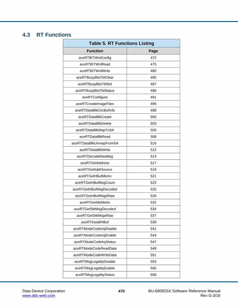
Data Device Corporation BU-69092SX Software Reference Manual www.ddc-web.com Rev G-3/16
470
4.3 RT Functions Table 5. RT Functions Listing
Function Page aceRTBITWrdConfig 472
aceRTBITWrdRead 475
aceRTBITWrdWrite 480
aceRTBusyBitsTblClear 485
aceRTBusyBitsTblSet 487
aceRTBusyBitsTblStatus 489
aceRTConfigure 491
aceRTCreateImageFiles 496
aceRTDataBlkCircBufInfo 498
aceRTDataBlkCreate 500
aceRTDataBlkDelete 503
aceRTDataBlkMapToSA 505
aceRTDataBlkRead 508
aceRTDataBlkUnmapFromSA 510
aceRTDataBlkWrite 512
aceRTDecodeRawMsg 514
aceRTGetAddress 517
aceRTGetAddrSource 519
aceRTGetHBufMetric 521
aceRTGetHBufMsgCount 523
aceRTGetHBufMsgDecoded 525
aceRTGetHBufMsgsRaw 529
aceRTGetStkMetric 532
aceRTGetStkMsgDecoded 534
aceRTGetStkMsgsRaw 537
aceRTInstallHBuf 539
aceRTModeCodeIrqDisable 541
aceRTModeCodeIrqEnable 543
aceRTModeCodeIrqStatus 547
aceRTModeCodeReadData 549
aceRTModeCodeWriteData 551
aceRTMsgLegalityDisable 553
aceRTMsgLegalityEnable 556
aceRTMsgLegalityStatus 558

R T F U N C T I O N D E F I N I T I O N S
Data Device Corporation BU-69092SX Software Reference Manual www.ddc-web.com Rev G-3/16
471
Table 5. RT Functions Listing
Function Page aceRTRelatchAddr 561
aceRTSetAddress 563
aceRTSetAddrSource 565
aceRTStart 567
aceRTStatusBitsClear 569
aceRTStatusBitsSet 572
aceRTStatusBitsStatus 575
aceRTStkToHBuf 577
aceRTStkToHBuf32 579
aceRTStop 581
aceRTUninstallHBuf 583

R T F U N C T I O N D E F I N I T I O N S
Data Device Corporation BU-69092SX Software Reference Manual www.ddc-web.com Rev G-3/16
472
aceRTBITWrdConfig This function configures the Built in Test word.
PROTOTYPE #include “Rt.h” S16BIT _DECL aceRTBITWrdConfig(S16BIT DevNum, U16BIT wBITLoc, U16BIT wBITBusyInh);
HARDWARE EMACE, E²MA, AceXtreme
STATE Ready, Run
MODE RT, RTMT, RTMT-I
PARAMETERS DevNum (input parameter) Logical Device Number Valid values: 0 – 31 wBITLoc (input parameter) Destination as to the type of BIT. Valid values: The following values will set/clear the External Bit Word Enable bit
15 of Configuration Register # 4 at memory location 0x08. ACE_RT_BIT_INTERNAL This value will clear bit 15 to a 0. The RT will respond to a Transmit
BIT word mode command with the contents of the hardware's internal BIT Word Register as the data word.
ACE_RT_BIT_EXTERNAL This value will set bit 15 to a 1. The 1553 hardware will access the
BIT data word from a location in the shared RAM. In this instance, the BIT Word must be written to RAM by the host processor.

R T F U N C T I O N D E F I N I T I O N S
Data Device Corporation BU-69092SX Software Reference Manual www.ddc-web.com Rev G-3/16
473
aceRTBITWrdConfig (continued) wBITBusyInh Inhibit RT Bit if Busy is active. Valid values: The following values will set/clear the Inhibit Bit Word Transmit If
Busy bit 14 of Configuration Register # 4 at memory location 0x08.
ACE_RT_BIT_NO_INHIBIT This value will clear bit 14 to a 0. In this case, the
1553 hardware will respond to a Transmit BIT Word mode command with its RT Status Word with the BUSY bit set, followed by its internal or external Built-in-Test (BIT) Word.
ACE_RT_BIT_INHIBIT
This value will set bit 14 to a 1. In this case, the 1553 hardware will respond with its RT Status Word with the BUSY bit set, but no Data Word (BIT Word) will be transmitted.
DESCRIPTION This function will set/clear bits 14 and 15 of Configuration Register # 4 at memory location 0x08 in order to configure the way in which the Built-in Test word will be read and written and whether or not it will be inhibited if the RT is busy. External BIT word is read (written) from the memory location that the transmit Mode BIT word mode code data would be stored (hardware mode code memory offset + 0x13). The internal BIT word is read (written) from the internal hardware BIT register.
RETURN VALUE ACE_ERR_SUCCESS The function completed successfully ACE_ERR_INVALID_DEVNUM An invalid device number was input by the user ACE_ERR_INVALID_STATE The device is not in a Ready or Run state ACE_ERR_INVALID_MODE The device is not in RT or RTMT mode

R T F U N C T I O N D E F I N I T I O N S
Data Device Corporation BU-69092SX Software Reference Manual www.ddc-web.com Rev G-3/16
474
aceRTBITWrdConfig (continued) EXAMPLE
S16BIT DevNum = 0; S16BIT nResult = 0; U16BIT wBITLoc = ACE_RT_BIT_INTERNAL; U16BIT wBITBusyInh = ACE_RT_BIT_INHIBIT; /* designate RT to read BIT word internally, and inhibit during Busy Bit active */ nResult = aceRTBITWrdConfig(DevNum, wBITLoc, wBITBusyInh); if(nResult < 0) { printf(“Error in aceRTBITWrdConfig() function \n”); PrintOutError(nResult); return; }
SEE ALSO aceRTBITWrdRead() aceRTBITWrdWrite()

R T F U N C T I O N D E F I N I T I O N S
Data Device Corporation BU-69092SX Software Reference Manual www.ddc-web.com Rev G-3/16
475
aceRTBITWrdRead This function will read the current BIT word from the device’s BIT register.
PROTOTYPE #include “Rt.h” S16BIT _DECL aceRTBITWrdRead(S16BIT DevNum, U16BIT wBITLoc, U16BIT *pBITWrd);
HARDWARE EMACE, E²MA, AceXtreme
STATE Ready, Run
MODE RT, RTMT, RTMT-I
PARAMETERS DevNum (input parameter) Logical Device Number Valid values: 0 – 31 wBITLoc (input parameter) Destination as to the type of BIT. Valid values: The following values will set/clear the External Bit Word Enable bit
15 of Configuration Register # 4 at memory location 0x08. ACE_RT_BIT_INTERNAL This value will clear bit 15 to a 0. The RT will respond to a
Transmit BIT word mode command with the contents of the internal BIT Word Register as the data word.
ACE_RT_BIT_EXTERNAL This value will set bit 15 to a 1. The hardware will access the BIT
data word from a location in the shared RAM. In this instance, the BIT Word must be written to RAM by the host processor.

R T F U N C T I O N D E F I N I T I O N S
Data Device Corporation BU-69092SX Software Reference Manual www.ddc-web.com Rev G-3/16
476
aceRTBITWrdRead (continued) pBITWrd (output parameter)
Pointer to an unsigned 16-bit value that will be filled with the BIT word value. The individual bit descriptions are given below. A 1 will represent the condition shown for the bit.
Valid values: Bit 15 Transmitter Timeout Set if the 1553 hardware failsafe timer detected a fault condition.
The transmitter timeout circuit will automatically shut down the CH. A or CH. B transmitter if it transmits for longer than 668 µs. In RT mode, the 1553 hardware will terminate the processing of the current message as the result of a transmitter timeout, however, it will respond to the next message received.
Bit 14, 13 Loop Test Failure B, Loop Test Failure A A loopback test is performed on the transmitted portion of every
non-broadcast message. A validity check is performed on the received version of every word transmitted by the 1553 hardware. In addition, a bit-by-bit comparison is performed on the last word transmitted by the RT for each message. If either the received version of any transmitted word is determined to be invalid (sync, encoding, bit count, or parity error) and/or the received version of the last transmitted word does not match the transmitted version, or a failsafe timeout occurs on the respective channel, the Loop Test Failure bit for the respective bus channel will be set.
Bit 12 Handshake Failure If this bit is set, it indicates that the subsystem has failed to respond
with the DMA handshake input DTGRT* asserted within the allotted time, in response to the hardware asserting DTREQ*. Alternatively, a handshake failure will occur if the host PROCESSOR fails to clear STRBD* (high) within the allotted time, after the hardware has asserted its READYD* output (low). The allotted time is 4 µs for a 16 MHz clock, or 3.5 µs for a 12 MHz clock. All of DDC’s COTS cards provide a 16 MHz clock.
Bit 11, Bit 10 Transmitter Shutdown B, Transmitter Shutdown A Indicates that the transmitter on the respective bus channel has
been shut down by a Transmitter shutdown mode code command received on the alternate channel. If an Override transmitter shutdown mode code command is received on the alternate channel, this bit will revert back to logic 0.

R T F U N C T I O N D E F I N I T I O N S
Data Device Corporation BU-69092SX Software Reference Manual www.ddc-web.com Rev G-3/16
477
aceRTBITWrdRead (continued) Bit 9 Terminal Flag Inhibited Set to logic 1 if the hardware's Terminal Flag RT Status bit has
been disabled by an Inhibit terminal flag mode code command. Will revert to logic 0 if an Override inhibit terminal flag mode code command is received.
Bit 8 Bit Test Fail Represents the result of the RT’s most recent built-in protocol self-
test. A value of logic 0 for bit 8 indicates that the test passed. The bit will return a value of logic 1 if the device has failed its most recent protocol self-test. If a subsequent performing of the protocol self-test passes, bit 8 will clear to 0. Also, note that the RAM self-test has no effect on bit 8.
Bit 7 High Word Count Set to logic 1 if the most recent message had a high word count
error. Bit 6 Low Word Count Set to logic 1 if the most recent message had a low word count
error. Bit 5 Incorrect Sync Received Set to a logic 1 if the 1553 hardware detected a Command sync in
a received Data Word. Bit 4 Invalid Word Received Indicates that the RT received a Data Word containing one or more
of the following error types: sync field error, Manchester encoding error, parity error, and/or bit count error.
Bit 3 RT-RT Gap/Sync/Address Error This bit is set if the RT is the receiving RT for an RT to RT transfer
and one or more of the following occurs: (1) If the GAP CHECK ENABLED bit (bit 8) of Configuration Register # 5 at memory location 0x09 is set to logic 1 and the transmitting RT responds with a response time of less than 4 µs, per MIL-STD-1553B (mid-parity bit to mid-sync); i.e., less than 2 µs dead time; and/or

R T F U N C T I O N D E F I N I T I O N S
Data Device Corporation BU-69092SX Software Reference Manual www.ddc-web.com Rev G-3/16
478
aceRTBITWrdRead (continued) (2) There is an incorrect sync type or format error (encoding, bit
count, and/or parity error) in the transmitting RT Status Word; and/or (3) The RT address field of the transmitting RT Status Word does not match the RT address in the transmit Command Word.
Bit 2 RT-RT No Response Error If this bit is set to a logic 1, this indicates that for the previous
message, the 1553 hardware was the receiving RT for an RT to RT transfer and that the transmitting RT either did not respond or responded later than the configured RT to RT Timeout time. The RT to RT Response Timeout Time is defined as the time from the mid-bit crossing of the parity bit of the transmit Command Word to the mid-sync crossing of the transmitting RT Status Word. The value of the RT to RT Response Timeout is 18.5 µs by default, or programmable from among nominal values of 18.5, 22.5, 50.5, or 130 µs by calling the aceSetRespTimeOut() function.
Bit 1 RT-RT 2nd Command Word Error If the 1553 hardware is the receiving RT for an RT to RT transfer,
this bit set to a logic 1 indicates one or more of the following error conditions in the transmit Command Word: (1) T/R bit = logic "0"; (2) subaddress = 00000 or 11111; (3) same RT address field as the receive Command Word.
Bit 0 Command Word Contents Error Indicates a received command word is not defined in accordance
with MIL-STD-1553B specifications. This includes the following undefined Command Words: (1) BROADCAST DISABLED - bit 7 of Configuration Register # 5 at memory location 0x09 is logic 0 and the Command Word is a non-mode code, broadcast, or transmit command; (2) The OVERRIDE MODE T/R* ERROR bit - bit 6 of Configuration Register # 3 at memory location 0x07 is logic 0 and a message with a T/R* bit of 0, a subaddress/mode field of 00000 or 11111 and a mode code field between 00000 and 01111; (3) BROADCAST DISABLED - bit 7 of Configuration Register # 5 is logic 0 and a mode code command that is not permitted to be broadcast (e.g., Transmit status) is sent to the broadcast address (11111).

R T F U N C T I O N D E F I N I T I O N S
Data Device Corporation BU-69092SX Software Reference Manual www.ddc-web.com Rev G-3/16
479
aceRTBITWrdRead (continued) DESCRIPTION
This function reads the current BIT word from the BIT register. External BIT word is read from the memory location that the transmit Mode BIT word mode code data would be stored (hardware mode code memory offset + 0x13). The internal BIT word is read from the internal RT BIT Word register.
RETURN VALUE ACE_ERR_SUCCESS The function completed successfully ACE_ERR_INVALID_DEVNUM An invalid device number was input by the user ACE_ERR_INVALID_STATE The device is not in a Ready or Run state ACE_ERR_INVALID_MODE The device is not in RT or RTMT mode ACE_ERR_PARAMETER The wBITLoc input parameter is greater than one
and/or the pBITWrd is Null
EXAMPLE S16BIT DevNum = 0; S16BIT nResult = 0; U16BIT pBITWrd; /* Read Internal BIT word from the RT BIT Word register. The BIT word is returned in parameter pBITWrd */ nResult = aceRTBITWrdRead(DevNum, ACE_RT_BIT_INTERNAL, &pBITWrd); if(nResult) { printf(“Error in aceRTBITWrdRead() function \n”); PrintOutError(nResult); return; }
SEE ALSO aceRTBITWrdConfig() aceRTBITWrdWrite()

R T F U N C T I O N D E F I N I T I O N S
Data Device Corporation BU-69092SX Software Reference Manual www.ddc-web.com Rev G-3/16
480
aceRTBITWrdWrite This function will write a BIT word to the external BIT word location.
PROTOTYPE #include “Rt.h” S16BIT _DECL aceRTBITWrdWrite(S16BIT DevNum, U16BIT *wBITWrd);
HARDWARE EMACE, E²MA, AceXtreme
STATE Ready, Run
MODE RT, RTMT, RTMT-I
PARAMETERS DevNum Logical Device Number Valid values: 0 – 31 wBITWrd (input parameter)
Pointer to an unsigned 16-bit value that will be written into the external BIT word location. The individual bit descriptions are given below. A 1 will represent the condition shown for the bit.
Valid values: Bit 15 Transmitter Timeout Set if the 1553 hardware failsafe timer detected a fault condition.
The transmitter timeout circuit will automatically shut down the CH. A or CH. B transmitter if it transmits for longer than 668 µs. In RT mode, the 1553 hardware will terminate the processing of the current message as the result of a transmitter timeout, however, it will respond to the next message received.
Bit 14, 13 Loop Test Failure B, Loop Test Failure A A loopback test is performed on the transmitted portion of every
non-broadcast message. A validity check is performed on the received version of every word transmitted by the 1553 hardware. In addition, a bit-by-bit comparison is performed on the last word transmitted by the RT for each message. If either the received version of any transmitted word is determined to be invalid (sync, encoding, bit count, or parity error) and/or

R T F U N C T I O N D E F I N I T I O N S
Data Device Corporation BU-69092SX Software Reference Manual www.ddc-web.com Rev G-3/16
481
aceRTBITWrdWrite (continued) the received version of the last transmitted word does not match
the transmitted version, or a failsafe timeout occurs on the respective channel, the Loop Test Failure bit for the respective bus channel will be set.
Bit 12 Handshake Failure If this bit is set, it indicates that the subsystem has
failed to respond with the DMA handshake input DTGRT* asserted within the allotted time, in response to the 1553 hardware asserting DTREQ*. Alternatively, a handshake failure will occur if the host PROCESSOR fails to clear STRBD* (high) within the allotted time, after the hardware has asserted its READYD* output (low). The allotted time is 4 µs for a 16 MHz clock, or 3.5 µs for a 12 MHz clock. All of DDC’s 1553 COTS cards provide a 16 MHz clock.
Bit 11, Bit 10 Transmitter Shutdown B, Transmitter Shutdown A Indicates that the transmitter on the respective bus channel has
been shut down by a Transmitter shutdown mode code command received on the alternate channel. If an Override transmitter shutdown mode code command is received on the alternate channel, this bit will revert back to logic 0.
Bit 9 Terminal Flag Inhibited Set to logic 1 if the Terminal Flag RT Status bit has been disabled
by an Inhibit terminal flag mode code command. Will revert to logic 0 if an Override inhibit terminal flag mode code command is received.
Bit 8 Bit Test Fail Represents the result of the RT’s most recent built-in protocol self-
test. A value of logic 0 for bit 8 indicates that the test passed. The bit will return a value of logic 1 if the 1553 hardware has failed its most recent protocol self-test. If a subsequent performing of the protocol self-test passes, bit 8 will clear to 0. Also, note that the RAM self-test has no effect on bit 8.
Bit 7 High Word Count Set to logic 1 if the most recent message had a high word count
error.

R T F U N C T I O N D E F I N I T I O N S
Data Device Corporation BU-69092SX Software Reference Manual www.ddc-web.com Rev G-3/16
482
aceRTBITWrdWrite (continued) Bit 6 Low Word Count Set to logic 1 if the most recent message had a low
word count error. Bit 5 Incorrect Sync Received Set to a logic 1 if the 1553 hardware detected a Command sync in
a received Data Word. Bit 4 Invalid Word Received Indicates that the RT received a Data Word containing one or more
of the following error types: sync field error, Manchester encoding error, parity error, and/or bit count error.
Bit 3 RT-RT Gap/Sync/Address Error This bit is set if the RT is the receiving RT for an RT to RT transfer
and one or more of the following occurs: (1) If the GAP CHECK ENABLED bit (bit 8) of Configuration Register # 5 at memory location 0x09 is set to logic 1 and the transmitting RT responds with a response time of less than 4 µs, per MIL-STD-1553B (mid-parity bit to mid-sync); i.e., less than 2 µs dead time; and/or (2) There is an incorrect sync type or format error (encoding, bit count, and/or parity error) in the transmitting RT Status Word; and/or (3) The RT address field of the transmitting RT Status Word does not match the RT address in the transmit Command Word.
Bit 2 RT-RT No Response Error If this bit is set to a logic 1, this indicates that for the previous
message, the 1553 hardware was the receiving RT for an RT to RT transfer and that the transmitting RT either did not respond or responded later than the RT to RT Timeout time. The RT to RT Response Timeout Time is defined as the time from the mid-bit crossing of the parity bit of the transmit Command Word to the mid-sync crossing of the transmitting RT Status Word. The value of the RT to RT Response Timeout is 18.5 µs by default, or programmable from among nominal values of 18.5, 22.5, 50.5, or 130 µs by calling the aceSetRespTimeOut() function.

R T F U N C T I O N D E F I N I T I O N S
Data Device Corporation BU-69092SX Software Reference Manual www.ddc-web.com Rev G-3/16
483
aceRTBITWrdWrite (continued) Bit 1 RT-RT 2nd Command Word Error If the 1553 hardware is the receiving RT for an
RT to RT transfer, this bit set to a logic 1 indicates one or more of the following error conditions in the transmit Command Word: (1) T/R bit = logic "0"; (2) subaddress = 00000 or 11111; (3) same RT address field as the receive Command Word.
Bit 0 Command Word Contents Error Indicates a received command word is not defined
in accordance with MIL-STD-1553B specifications. This includes the following undefined Command Words: (1) BROADCAST DISABLED - bit 7 of Configuration Register # 5 at memory location 0x09 is logic 0 and the Command Word is a non-mode code, broadcast, or transmit command; (2) The OVERRIDE MODE T/R* ERROR bit - bit 6 of Configuration Register # 3 at memory location 0x07 is logic 0 and a message with a T/R* bit of 0, a subaddress/mode field of 00000 or 11111 and a mode code field between 00000 and 01111; (3) BROADCAST DISABLED - bit 7 of Configuration Register # 5 is logic 0 and a mode code command that is not permitted to be broadcast (e.g., Transmit status) is sent to the broadcast address (11111).
DESCRIPTION This function writes the BIT word if set as external. External BIT word is written to the memory location that the transmit Mode BIT word mode code data would be stored (hardware mode code memory offset + 0x13). If the location is configured as internal, this function will return ACE_ERR_PARAMETER.
RETURN VALUE ACE_ERR_SUCCESS The function completed successfully ACE_ERR_INVALID_DEVNUM An invalid device number was input by the user ACE_ERR_INVALID_STATE The device is not in a Ready or Run state ACE_ERR_INVALID_MODE The device is not in RT or RTMT mode ACE_ERR_PARAMETER The BIT location has been configured as
ACE_RT_BIT_INTERNAL

R T F U N C T I O N D E F I N I T I O N S
Data Device Corporation BU-69092SX Software Reference Manual www.ddc-web.com Rev G-3/16
484
aceRTBITWrdWrite (continued) EXAMPLE
S16BIT DevNum = 0; S16BIT nResult = 0; U16BIT wBITWrd = 0x5555; // Write External BIT. The BIT word configuration must specify External nResult = aceRTBITWrdWrite(DevNum, &wBITWrd); if(nResult) { printf(“Error in aceRTBITWrdWrite() function \n”); PrintOutError(nResult); return; }
SEE ALSO aceRTBITWrdConfig() aceRTBITWrdRead()

R T F U N C T I O N D E F I N I T I O N S
Data Device Corporation BU-69092SX Software Reference Manual www.ddc-web.com Rev G-3/16
485
aceRTBusyBitsTblClear This function will disable certain subaddresses from returning the BUSY bit in their status word set to a 1.
PROTOTYPE #include “Rt.h” S16BIT _DECL aceRTBusyBitsTblClear(S16BIT DevNum, U16BIT wOwnAddrOrBcst, U16BIT wTR, U32BIT dwSAMask);
HARDWARE EMACE, E²MA, AceXtreme
STATE Ready, Run
MODE RT, RTMT, RTMT-I
PARAMETERS DevNum (input parameter) Logical Device Number Valid values: 0 – 31 wOwnAddrOrBcst (input parameter)
This parameter specifies whether the RT address is own or broadcast Valid values: ACE_RT_OWN_ADDRESS ACE_RT_BCST_ADDRSS ACE_RT_MODIFY_ALL wTR (input parameter) Specify the direction Transmit/Receive Valid values: 1 = Transmit 0 = Receive ACE_RT_MODIFY_ALL dwSAMask (input parameter) An unsigned 32-bit packed value that represents the
subaddresses that should respond with the BUSY bit cleared to a value of 0 in the status word. A ‘1’ indicates the BUSY BIT should be inactive. The value is an OR’ed combination of the following values.

R T F U N C T I O N D E F I N I T I O N S
Data Device Corporation BU-69092SX Software Reference Manual www.ddc-web.com Rev G-3/16
486
aceRTBusyBitsTblClear (continued) Valid value: ACE_RT_SAXX Specifies the subaddress where XX = 0 – 31 ACE_RT_SA_ALL Selects all subaddresses
DESCRIPTION This function will disable a selected subaddress from setting the BUSY bit in their status words. The table is set based on the type of message as defined by the following parameters: Own Address/Bcst* T/R* Using the ACE_RT_MODIFY_ALL constant will clear the status word BUSY bit for all messages of a certain type. In addition to this you can use the ACE_RT_SA_ALL constant to disable the BUSY bit for all subaddresses.
RETURN VALUE ACE_ERR_SUCCESS The function completed successfully ACE_ERR_INVALID_DEVNUM An invalid device number was input by the user ACE_ERR_INVALID_STATE The device is not in a Ready or Run state ACE_ERR_INVALID_MODE The device is not in RT or RTMT mode ACE_ERR_PARAMETER The wTR and/or the wOwnAddrOrBcst input
parameter(s) contain an incorrect value
EXAMPLE S16BIT DevNum = 0; S16BIT nResult = 0; U16BIT wOwnAddrOrBcst = 1, wTR = 1; U32BIT dwSAMask = (ACE_RT_SA0 | ACE_RT_SA22 | ACE_RT_SA25); nResult = aceRTBusyBitsTblClear(DevNum, wOwnAddrOrBcst, wTR, dwSAMask); if(nResult) { printf(“Error in aceRTBusyBitsTblClear() function \n”); PrintOutError(nResult); return; }
SEE ALSO aceRTBusyBitsTblSet() aceRTBusyBitsTblStatus()

R T F U N C T I O N D E F I N I T I O N S
Data Device Corporation BU-69092SX Software Reference Manual www.ddc-web.com Rev G-3/16
487
aceRTBusyBitsTblSet This function will enable certain subaddresses to return the BUSY bit in their status word set to a 1.
PROTOTYPE #include “Rt.h” S16BIT _DECL aceRTBusyBitsTblSet(S16BIT DevNum, U16BIT wOwnAddrOrBcst, U16BIT wTR, U32BIT dwSAMask)
HARDWARE EMACE, E²MA, AceXtreme
STATE Ready, Run
MODE RT, RTMT, RTMT-I
PARAMETERS DevNum (input parameter) Logical Device Number Valid values: 0 – 31 wOwnAddrOrBcst (input parameter)
This parameter specifies whether the RT address is own or broadcast Valid values: ACE_RT_OWN_ADDRESS ACE_RT_BCST_ADDRSS ACE_RT_MODIFY_ALL wTR (input parameter) Specify the direction Transmit/Receive Valid values: 1 = Transmit 0 = Receive ACE_RT_MODIFY_ALL dwSAMask (input parameter)
An unsigned 32-bit packed value that represents the subaddresses that should respond with the BUSY bit set in the status word. A ‘1’ indicates the BUSY bit should be active. The value is an OR’ed combination of the following values.
R T F U N C T I O N D E F I N I T I O N S
Data Device Corporation BU-69092SX Software Reference Manual www.ddc-web.com Rev G-3/16
488
aceRTBusyBitsTblSet (continued) Valid value: ACE_RT_SAXX Specifies the subaddress where XX = 0 – 31 ACE_RT_SA_ALL Selects all subaddresses
DESCRIPTION This function will enable certain subaddresses to return the BUSY bit in their status words set. The table is set based on the type of message as defined by the following parameters: Own Address/Bcst* T/R* Using the ACE_RT_MODIFY_ALL constant will set the status word BUSY BIT for all messages of a certain type. In conjunction with this you can use the ACE_RT_SA_ALL constant to make all subaddresses respond with the busy bit set.
RETURN VALUE ACE_ERR_SUCCESS The function completed successfully ACE_ERR_INVALID_DEVNUM An invalid device number was input by the user ACE_ERR_INVALID_STATE The device is not in a Ready or Run state ACE_ERR_INVALID_MODE The device is not in RT or RTMT mode ACE_ERR_PARAMETER The wTR and/or the wOwnAddrOrBcst input
parameter(s) contain an incorrect value
EXAMPLE S16BIT DevNum = 0; S16BIT nResult = 0; U16BIT wOwnAddrOrBcst = 1, wTR = 1; U32BIT dwSAMask = ACE_RT_SA0 | ACE_RT_SA22 | ACE_RT_SA25; nResult = aceRTBusyBitsTblSet(DevNum, wOwnAddrOrBcst, wTR, dwSAMask); if(nResult) { printf(“Error in aceRTBusyBitsTblSet() function \n”); PrintOutError(nResult); return; }
SEE ALSO aceRTBusyBitsTblClear() aceRTBusyBitsTblStatus()
R T F U N C T I O N D E F I N I T I O N S
Data Device Corporation BU-69092SX Software Reference Manual www.ddc-web.com Rev G-3/16
489
aceRTBusyBitsTblStatus This function reports the status of the BUSY bit.
PROTOTYPE #include “Rt.h” S16BIT _DECL aceRTBusyBitsTblStatus(S16BIT DevNum, U16BIT wOwnAddrOrBcst, U16BIT wTR, U32BIT *pdwSABusyBits);
HARDWARE EMACE, E²MA, AceXtreme
STATE Ready, Run
MODE RT, RTMT, RTMT-I
PARAMETERS DevNum (input parameter) Logical Device Number Valid values: 0 – 31 wOwnAddrOrBcst (input parameter)
This parameter specifies whether the RT address is own or broadcast Valid values: ACE_RT_OWN_ADDRESS ACE_RT_BCST_ADDRSS wTR (input parameter) Specify the direction Transmit/Receive Valid values: 1 = Transmit 0 = Receive

R T F U N C T I O N D E F I N I T I O N S
Data Device Corporation BU-69092SX Software Reference Manual www.ddc-web.com Rev G-3/16
490
aceRTBusyBitsTblStatus (continued) pdwSABusyBits (output parameter)
An unsigned 32-bit packed value that represents the subaddresses that are presently setup to return the BUSY bit set in the status word to a value of 1. A 1 in this 32-bit packed value indicates the BUSY bit is active. The value returned may be masked with the following macros for decoding.
Valid value: ACE_RT_SAXX Specifies the subaddress where XX = 0 – 31 ACE_RT_SA_ALL All subaddresses
DESCRIPTION This function reads the Busy Bit table and reports the status of each of the 32 subaddresses for a particular type of command.
RETURN VALUE ACE_ERR_SUCCESS The function completed successfully ACE_ERR_INVALID_DEVNUM An invalid device number was input by the user ACE_ERR_INVALID_STATE The device is not in a Ready or Run state ACE_ERR_INVALID_MODE The device is not in RT or RTMT mode ACE_ERR_PARAMETER The wTR and/or the wOwnAddrOrBcst input
parameter(s) contain an incorrect value and/or the pdwSABusyBits is Null
EXAMPLE S16BIT DevNum = 0; U16BIT wOwnAddrOrBcst = ACE_RT_OWN_ADDRESS, wTR = 1; U32BIT pdwSABusyBits; /* the value returned in pdwSABusyBits can be decoded by masking with the Subaddress macros (ACE_RT_SAXX) */ nResult = aceRTBusyBitsTblStatus(DevNum, wOwnAddrOrBcst, wTR, &pdwSABusyBits) if(nResult) { printf(“Error in aceRTBusyBitsTblStatus() function \n”); PrintOutError(nResult); return; }
SEE ALSO aceRTBusyBitsTblClear() aceRTBusyBitsTblSet()

R T F U N C T I O N D E F I N I T I O N S
Data Device Corporation BU-69092SX Software Reference Manual www.ddc-web.com Rev G-3/16
491
aceRTConfigure This function configures a RT.
PROTOTYPE #include “Rt.h” S16BIT _DECL aceRTConfigure(S16BIT DevNum, U16BIT wCmdStkSize, U32BIT dwOptions);
HARDWARE EMACE, E²MA, AceXtreme
STATE Ready
MODE RT
PARAMETERS DevNum (input parameter) Logical Device Number Valid values: 0 – 31 wCmdStkSize (input parameter) This is the size of the desired RT command stack size Valid values: ACE_RT_CMDSTK_256 256 words ACE_RT_CMDSTK_512 512 words ACE_RT_CMDSTK_1K 1024 words ACE_RT_CMDSTK_2K 2048 words dwOptions (input parameter)
The options designate the operation of the RT. The value is an U32BIT value that is an OR’ed combination of the following values.
Valid values: The following parameters will set bits in Configuration Register # 2
at memory location 0x02:

R T F U N C T I O N D E F I N I T I O N S
Data Device Corporation BU-69092SX Software Reference Manual www.ddc-web.com Rev G-3/16
492
aceRTConfigure (continued) ACE_RT_OPT_CLR_SREQ Sets the Clear Service Request bit 2 to a 1. This will clear a service request after a tx vector word. ACE_RT_OPT_LOAD_TT Sets the Load/Transmit Time Tag on Synchronize bit 5 to a 1. This will cause the reception of a Synchronize (with data) mode
command, which will cause the Data Word from the Synchronize message to be loaded into the Time Tag Register.
ACE_RT_OPT_CLEAR_TT Sets the Clear Time Tag on Synchronize bit 6 to a 1. This will cause the reception of a Synchronize (without data) mode
command, which will cause the value of the internal Time Tag Register to clear to 0x0000.
ACE_RT_OPT_OVR_DATA Sets the Overwrite Invalid Data bit 11 to a 1. This affects the operation of the RT subaddress circular buffer
memory management mode. The Lookup Table address pointer will only be updated following a transmit message or following a valid receive or broadcast message to the respective Rx/Bcst subaddress. If the bit is logic 1, the Lookup Table pointer will not be updated following an invalid receive or broadcast message. In addition, if the bit is logic 1, an interrupt request for a circular buffer rollover condition (if enabled) will only occur following the end of a transmit message during which the last location in the circular buffer has been read or following the end of a valid receive or Broadcast message in which the last location in the circular buffer has been written to.
The following parameters will set bits in
Configuration Register # 3 at memory location 0x07: ACE_RT_OPT_OVR_MBIT Sets Override Mode T/R* Error bit 6 to a 1. This will cause a mode code Command Word with a T/R* bit of 0
and an MSB of the mode code field of 0 will be considered a defined (reserved) mode Command Word. In this configuration, the 1553 hardware will respond to such a command and the Message Error bit will not become set.

R T F U N C T I O N D E F I N I T I O N S
Data Device Corporation BU-69092SX Software Reference Manual www.ddc-web.com Rev G-3/16
493
aceRTConfigure (continued) ACE_RT_OPT_ALT_STS
Sets Alternate RT Status Word Enable bit 5 toa 1. This will cause all 11 RT Status Word bits to be under control of the host processor, by means of bits 11 through 1 of Configuration Register # 1.
ACE_RT_OPT_IL_RX_D Sets Illegal Receive Transfer Disable bit 4 to a 1.
This will cause the device to not store the received data words to the shared RAM if the ACE receives a receive command that has been illegalized,
ACE_RT_OPT_BSY_RX_D Sets Busy Receive Transfer Disable bit 3 to a 1. If the host processor has programmed BUSY* to logic "0" or the
particular Command Word (broadcast, T/R* bit, subaddress) has been programmed to be busy by means of the Busy lookup table and the RT receives a receive command, the 1553 device will respond with its Status Word with the Busy bit set and will not store the received Data Words to the shared RAM.
ACE_RT_OPT_SET_RTFG Sets RTFail*/RTFlag* Wrap Enable bit 2 to a 1.
The Terminal flag status word bit will also become set if either a transmitter timeout (660.5 µs) condition had occurred or the ACE RT had failed its loopback test for the previous non-broadcast message. The loopback test is performed on all non-broadcast messages processed by the RT. The received version of all transmitted words is checked for validity (sync and data encoding, bit count, parity) and correct sync type. In addition, a 16-bit comparison is performed on the received version of the last word transmitted by the RT. If any of these checks or comparisons do not verify, the loopback test is considered to have failed.
ACE_RT_OPT_1553A_MC Sets 1553A Mode Codes Enabled bit 1 to a 1. If this option is chosen, the RT or Message Monitor considers only
subaddress 0 to be a mode code subaddress. Subaddress 31 is treated as a standard non-mode code subaddress. In this configuration, the 1553 hardware will consider valid and respond only to mode code commands containing no data words. In this configuration, the RT will consider all mode commands followed by data words to be invalid and will not respond. In addition, the 1553 hardware will not decode for the MIL-STD-1553B "Transmit Status" and "Transmit Last Command" mode codes.

R T F U N C T I O N D E F I N I T I O N S
Data Device Corporation BU-69092SX Software Reference Manual www.ddc-web.com Rev G-3/16
494
aceRTConfigure (continued) As a result, the internal RT Status Word Register will be updated as
a result of these commands. The following parameters will set bits in Configuration Register # 4
at memory location 0x08: ACE_RT_OPT_MC_O_BSY Sets Mode Command Override Busy Bit 13 to a 1.
If BUSY* is programmed to logic "0" or if Busy Lookup Table (bit 13 of Configuration Register #2) is logic "1" and the respective bit(s) in the Busy Lookup Table (bit 0 of location 0242 and/or bit 15 of location 0243) is programmed to logic "1," the 1553 hardware will transmit its Status Word with its BUSY bit set, followed by a single Data Word, in response to either a Transmit Vector Word mode command or a Reserved transmit mode command with data (transmit mode codes 10110 through 11111). The Busy Lookup Table functions are: aceRTBusyBitsTblSet(), aceRTBusyBitsTblClear(), and aceRTBusyBitsTblStatus().
The following parameters will set bits in Configuration Register # 5
at memory location 0x09: ACE_RT_OPT_BCST_DIS Sets Broadcast Disabled bit 7 to a 1. The 1553 hardware will not recognize RT address 31 as the
broadcast address. In this instance, RT address 31 may be used as a discrete RT address.
DESCRIPTION This function configures the Remote Terminal configuration. This routine initializes the device for operation as an RT. The SDK configuration structures and data tables are initialized to default values, and the memory structures are created. All RT subaddresses are illegalized after this function has been called.
RETURN VALUE ACE_ERR_SUCCESS The function completed successfully ACE_ERR_INVALID_DEVNUM An invalid device number was input by the user ACE_ERR_INVALID_STATE The device is not in a Ready state ACE_ERR_INVALID_MODE The device is not in RT mode ACE_ERR_PARAMETER The wCmdStkSize input parameter contains an
invalid value

R T F U N C T I O N D E F I N I T I O N S
Data Device Corporation BU-69092SX Software Reference Manual www.ddc-web.com Rev G-3/16
495
aceRTConfigure (continued) EXAMPLE
S16BIT DevNum = 0; S16BIT nResult = 0; U32BIT dwOptions = ACE_RT_OPT_SET_RTFG | ACE_RT_OPT_LOAD_TT; // Initiate RT with a 512 word command stack //Load time tag on sync mode code and set flag if loop back test fails nResult = aceRTConfigure(DevNum, ACE_RT_CMDSTK_512, dwOptions); if(nResult) { printf(“Error in aceRTConfigure() function \n”); PrintOutError(nResult); return; }
SEE ALSO aceRTMTConfigure() aceMTConfigure()

R T F U N C T I O N D E F I N I T I O N S
Data Device Corporation BU-69092SX Software Reference Manual www.ddc-web.com Rev G-3/16
496
aceRTCreateImageFiles This function will create image files.
PROTOTYPE #include “Rt.h” S16BIT _DECL aceRTCreateImageFiles(S16BIT DevNum, char *pszIFile, char *pszHFile);
HARDWARE EMACE, E²MA, AceXtreme
STATE Ready
MODE RT
PARAMETERS DevNum (input parameter) Logical Device Number Valid values: 0 – 31 psziFile (output parameter)
A character pointer to a string that contains the name of the file where the image will be saved.
pszHFile (output parameter)
A character pointer to a string that contains the name of the file where the header information will be saved.
DESCRIPTION This function creates two files. The first is a binary image of the 1553 hardware memory after it is initialized and setup by the appropriate functions. The second is a 'C' header file that contains all memory and structure offsets. The header file also contains interface functions that provide access to the hardware without the need for the entire SDK.
RETURN VALUE ACE_ERR_SUCCESS The function completed successfully ACE_ERR_INVALID_DEVNUM An invalid device number was input by the user ACE_ERR_INVALID_STATE The device is not in a Ready state ACE_ERR_INVALID_MODE The device is not in RT mode ACE_ERR_PARAMETER The pszIFile parameter is Null and/or the pszHFile
parameter is Null

R T F U N C T I O N D E F I N I T I O N S
Data Device Corporation BU-69092SX Software Reference Manual www.ddc-web.com Rev G-3/16
497
aceRTCreateImageFiles (continued) EXAMPLE
S16BIT DevNum = 0; S16BIT nResult = 0; char pszIFile = “RTIMAGE.IMG”, pszHFile = “RTIMAGE.H”; nResult = aceRTCreateImageFiles(DevNum, pszIFile, pszHFile); if(nResult) { printf(“Error in aceRTCreateImageFiles() function \n”); PrintOutError(nResult); return; }
SEE ALSO None

R T F U N C T I O N D E F I N I T I O N S
Data Device Corporation BU-69092SX Software Reference Manual www.ddc-web.com Rev G-3/16
498
aceRTDataBlkCircBufInfo This function will return information about the circular buffer.
PROTOTYPE #include “Rt.h” S16BIT _DECL aceRTDataBlkCircBufInfo(S16BIT DevNum, S16BIT nDataBlkID, U16BIT *pUserRWOffset, U16BIT *pAceRWOffset);
STATE Ready, Run
MODE RT, RTMT, RTMT-I
PARAMETERS DevNum (input parameter) Logical Device Number Valid values: 0 – 31 nDataBlkID (input parameter) Unique data block ID that was supplied by the user during data block creation. Valid values: >=0 pUserRWOffset (output parameter)
Pointer to an unsigned 16-bit word to be filled with the last location read or written by the user.
pAceRWOffset (output parameter)
Pointer to an unsigned 16-bit word to be filled with the last location read/written by the hardware.
DESCRIPTION This function returns information about a circular buffer. This info includes the last read or written location performed by the user and the last location read or written by the hardware itself.
Note: The addresses are offsets based on the starting address of the circular buffer in the hardware. If the User Offset = 32 and the Card Offset = 0, then 96 will be returned.

R T F U N C T I O N D E F I N I T I O N S
Data Device Corporation BU-69092SX Software Reference Manual www.ddc-web.com Rev G-3/16
499
aceRTDataBlkCircBufInfo (continued) RETURN VALUE
S16BIT nResult returns the difference in Offset locations, counting forward, between the User Offset and the Card Offset (for example, If the User Offset = 32 and the Card Offset = 0, then 96 will be returned).
ACE_ERR_INVALID_DEVNUM An invalid device number was input by the user ACE_ERR_INVALID_STATE The device is not in a Ready or Run state ACE_ERR_INVALID_MODE The device is not in RT or RTMT mode ACE_ERR_PARAMETER The nDataBlkID input parameter is less than zero
and/or the pUserRWOffset parameter is Null and/or the pAceRWOffset parameter is Null
ACE_ERR_NODE_NOT_FOUND The data block specified by the nDataBlkID input parameter does not exist
ACE_ERR_RT_DBLK_NOT_CB The data block specified by the nDataBlkID input parameter is not defined to be a circular buffer
EXAMPLE S16BIT DevNum = 0; S16BIT nResult = 0; S16BIT nDataBlkID = 42; U16BIT pUserRWOffset, pAceRWOffset; nResult = aceRTDataBlkCircBufInfo(DevNum, nDataBlkID, &pUserRWOffset, &pAceRWOffset); if(nResult) { printf(“Error in aceRTDataBlkCircBufInfo() function \n”); PrintOutError(nResult); return; } printf(“Last user R/W at %x, \nLast hardware R/W at %x\n”, pUserRWOffset, pAceRWOffset);
SEE ALSO None

R T F U N C T I O N D E F I N I T I O N S
Data Device Corporation BU-69092SX Software Reference Manual www.ddc-web.com Rev G-3/16
500
aceRTDataBlkCreate This function creates an RT data block to be used.
PROTOTYPE #include “Rt.h” S16BIT _DECL aceRTDataBlkCreate(S16BIT DevNum, S16BIT nDataBlkID, U16BIT wDataBlkType, U16BIT *pBuffer, U16BIT wBufferSize);
HARDWARE EMACE, E²MA, AceXtreme
STATE Ready
MODE RT, RTMT, RTMT-I
PARAMETERS DevNum (input parameter) Logical Device Number Valid values: 0 – 31 nDataBlkID (input parameter)
A unique user supplied ID that will identify this data block for future use and removal
Valid values: >0 wDataBlkType The type of data block to be allocated Valid Values: 1 - 32 This value defines the number of words for Single Buffer Mode ACE_RT_DBLK_DOUBLE Double buffered message datablock 64 words long ACE_RT_DBLK_C_128 Circular buffer 128 words long ACE_RT_DBLK_C_256 Circular buffer 256 words long
R T F U N C T I O N D E F I N I T I O N S
Data Device Corporation BU-69092SX Software Reference Manual www.ddc-web.com Rev G-3/16
501
aceRTDataBlkCreate (continued) ACE_RT_DBLK_C_512 Circular buffer 512 words long ACE_RT_DBLK_C_1K Circular buffer 1024 words long ACE_RT_DBLK_C_2K Circular buffer 2048 words long ACE_RT_DBLK_C_4K Circular buffer 4096 words long ACE_RT_DBLK_C_8K Circular buffer 8192 words long ACE_RT_DBLK_GBL_C_128 Global circular buffer 128 words long ACE_RT_DBLK_GBL_C_256 Global circular buffer 256 words long ACE_RT_DBLK_GBL_C_512 Global circular buffer 512 words long ACE_RT_DBLK_GBL_C_1K Global circular buffer 1024 words long ACE_RT_DBLK_GBL_C_2K Global circular buffer 2048 words long ACE_RT_DBLK_GBL_C_4K Global circular buffer 4096 words long ACE_RT_DBLK_GBL_C_8K Global circular buffer 8192 words long pBuffer (input parameter)
Address of a U16BIT buffer containing info to be copied to the created data block
wBufferSize (input parameter) Number of words in buffer to be copied into the created data block
DESCRIPTION This function creates an RT data block identified by the nDataBlkID input parameter. After this data block has been created, it can be used by an RT at any subaddress.

R T F U N C T I O N D E F I N I T I O N S
Data Device Corporation BU-69092SX Software Reference Manual www.ddc-web.com Rev G-3/16
502
aceRTDataBlkCreate (continued)
RETURN VALUE ACE_ERR_SUCCESS The function completed successfully ACE_ERR_INVALID_DEVNUM An invalid device number was input by the user ACE_ERR_INVALID_STATE The device is not in a Ready state ACE_ERR_INVALID_MODE The device is not in RT or RTMT mode ACE_ERR_PARAMETER The wDataBlkType and/or nDataBlkID input
parameter(s) contain an incorrect value ACE_ERR_MEMMGR_FAIL Memory for the data block could not be allocated ACE_ERR_RT_DBLK_ALLOC A new data block could not be created
EXAMPLE S16BIT DevNum = 0; S16BIT nResult = 0; S16BIT nDataBlkID = 42; U16BIT pBuffer[1024], wBufferSize = 1024; /* Load pBuffer from external data file */ /* create a 1K data block as a circular buffer and initialize it to data that was read from an external file */ nResult = aceRTDataBlkCreate(DevNum, nDataBlkID, ACE_RT_DBLK_C_1K, pBuffer, wBufferSize); if(nResult) { printf(“Error in aceRTDataBlkCreate() function \n”); PrintOutError(nResult); return; }
SEE ALSO aceRTDataBlkDelete()

R T F U N C T I O N D E F I N I T I O N S
Data Device Corporation BU-69092SX Software Reference Manual www.ddc-web.com Rev G-3/16
503
aceRTDataBlkDelete This function will delete a data block.
PROTOTYPE #include “Rt.h” BIT _DECL aceRTDataBlkDelete(S16BIT DevNum, S16BIT nDataBlkID);
HARDWARE EMACE, E²MA, AceXtreme
STATE Ready
MODE RT, RTMT, RTMT-I
PARAMETERS DevNum (input parameter) Logical Device Number Valid values: 0 – 31 nDataBlkID (input parameter)
Unique user supplied ID that identifies the data block that was previously created using the aceRTDataBlkCreate() function.
Valid values: >0
DESCRIPTION This function removes a data block from memory and frees all resources associated with it.
RETURN VALUE ACE_ERR_SUCCESS The function completed successfully ACE_ERR_INVALID_DEVNUM An invalid device number was input by the user ACE_ERR_INVALID_STATE The device is not in a Ready state ACE_ERR_INVALID_MODE The device is not in RT or RTMT mode ACE_ERR_PARAMETER The nDataBlkID input parameter specified by the
user contains a value less than zero ACE_ERR_NODE_NOT_FOUND The data block specified by the nDataBlkID input
parameter does not exist

R T F U N C T I O N D E F I N I T I O N S
Data Device Corporation BU-69092SX Software Reference Manual www.ddc-web.com Rev G-3/16
504
aceRTDataBlkDelete (continued) EXAMPLE
S16BIT DevNum = 0; S16BIT nResult = 0; S16BIT nDataBlkID = 42; nResult = aceRTDataBlkDelete(DevNum, nDataBlkID) if(nResult) { printf(“Error in aceRTDataBlkDelete() function \n”); PrintOutError(nResult); return; }
SEE ALSO aceRTDataBlkCreate()

R T F U N C T I O N D E F I N I T I O N S
Data Device Corporation BU-69092SX Software Reference Manual www.ddc-web.com Rev G-3/16
505
aceRTDataBlkMapToSA This function maps a data block to a subaddress.
PROTOTYPE #include “Rt.h” S16BIT _DECL aceRTDataBlkMapToSA(S16BIT DevNum, S16BIT nDataBlkID, U16BIT wSA, U16BIT wMsgType, U16BIT wIrqOptions, U16BIT wLegalizeSA)
HARDWARE EMACE, E²MA, AceXtreme
STATE Ready, Run
MODE RT, RTMT, RTMT-I
PARAMETERS DevNum (input parameter) Logical Device Number Valid values: 0 – 31 nDataBlkID (input parameter)
The unique user supplied ID of the previously created data block that will be mapped to an SA. The user provided this ID during creation of the data block with the aceRTDataBlkCreate() function.
Valid values: >0 wSA (input parameter) The subaddress to be mapped Valid values: 0 – 31 wMsgType (input parameter)
Description of the message types that will be mapped by this command. This parameter is generated by OR’ing the following message types together.

R T F U N C T I O N D E F I N I T I O N S
Data Device Corporation BU-69092SX Software Reference Manual www.ddc-web.com Rev G-3/16
506
aceRTDataBlkMapToSA (continued) Valid values: ACE_RT_MSGTYPE_RX ACE_RT_MSGTYPE_TX ACE_RT_MSGTYPE_BCST ACE_RT_MSGTYPE_ALL wIrqOptions (input parameter)
Interrupts will be generated based on the value of this parameter. The value for this parameter can be 0 or any of the following macros "OR’ed" together.
Valid values: 0 No IRQ options ACE_RT_DBLK_EOM_IRQ (end of message) This will cause an interrupt at the end of the message to be set in
the RT Subaddress Control Word. An interrupt will be created at the end of every message if the EOM bit is set in the Interrupt Mask Register by calling the aceSetIrqConditions() function.
ACE_RT_DBLK_CIRC_IRQ (circular buffer) This will cause an interrupt when the circular buffer rolls over. An
interrupt will be created if one of the CIRCBUF_ROVER bits is set in the Interrupt Mask Register by calling the aceSetIrqConditions() function.
wLegalizeSA If this value is set to TRUE, then the Subaddress being mapped will also be legalized.
Valid values: TRUE FALSE
DESCRIPTION This function maps a Data Block (defined using aceRTDataBlkCreate) with one of the 32 subaddresses of the RT. The parameters are the RT subaddress (0-31), the Data Block ID, the type of messages that will use the Data Block (Tx, Rx, and/or Bcst), and the options for messages received that will access this data block. If the subaddress being mapped is not legal, the Legalize parameter may be set to TRUE in order to legalize it.
RETURN VALUE ACE_ERR_SUCCESS The function completed successfully ACE_ERR_INVALID_DEVNUM An invalid device number was input by the user ACE_ERR_INVALID_STATE The device is not in a Ready or Run state ACE_ERR_INVALID_MODE The device is not in RT or RTMT mode

R T F U N C T I O N D E F I N I T I O N S
Data Device Corporation BU-69092SX Software Reference Manual www.ddc-web.com Rev G-3/16
507
aceRTDataBlkMapToSA (continued) ACE_ERR_PARAMETER The nDataBlkID parameter contains a value less
than zero, and/or the wSA input parameter is greater than 31, and/or the wMsgType input parameter is 0 or greater than 7
ACE_ERR_NODE_NOT_FOUND The data block specified by the nDataBlkID input parameter does not exist
S16BIT nResult The data block is already mapped to the subaddress specified by the nResult value
EXAMPLE S16BIT DevNum = 0; S16BIT nResult = 0 S16BIT nDataBlkID = 42; U16BIT wSA = 13, wMsgType = ACE_RT_MSGTYPE_RX; U16BIT wIrqOptions = ACE_RT_DBLK_CIRC_IRQ; U16BIT wLegalizeSA = TRUE; /* Create data block. Map to SA13 for Receive messages. Options for generating interrupt is for circular buffer rollover. If this Subaddress is not legal, then legalize it all done by the aceRTDataBlkMapToSA() function */ nResult = aceRTDataBlkMapToSA(DevNum, nDataBlkID, wSA, wMsgType, wIrqOptions, wLegalizeSA); if(nResult) { printf(“Error in aceRTDataBlkMapToSA() function \n”); PrintOutError(nResult); return; }
SEE ALSO aceRTDataBlkUnmapFromSA()

R T F U N C T I O N D E F I N I T I O N S
Data Device Corporation BU-69092SX Software Reference Manual www.ddc-web.com Rev G-3/16
508
aceRTDataBlkRead This function reads data from a data block.
PROTOTYPE #include “Rt.h” S16BIT _DECL aceRTDataBlkRead(S16BIT DevNum, S16BIT nDataBlkID, U16BIT *pBuffer, U16BIT wBufferSize, U16BIT wOffset);
HARDWARE EMACE, E²MA, AceXtreme
STATE Ready, Run
MODE RT, RTMT, RTMT-I
PARAMETERS DevNum (input parameter) Logical Device Number Valid values: 0 – 31 nDataBlkID (input parameter)
Unique user supplied ID that was established during data block creation with the aceRTDataBlkCreate() function.
Valid values: >0 pBuffer (output parameter) Pointer to an unsigned 16-bit user buffer that will receive the data from the
data block wBufferSize The size of the buffer in words Valid values: >0 wOffset Offset into data buffer where read data will be written to Valid values: >=0
R T F U N C T I O N D E F I N I T I O N S
Data Device Corporation BU-69092SX Software Reference Manual www.ddc-web.com Rev G-3/16
509
aceRTDataBlkRead (continued) DESCRIPTION
This function transfers data from a hardware data block to a host buffer given the unique data block ID and device number.
RETURN VALUE ACE_ERR_INVALID_DEVNUM An invalid device number was input by the user ACE_ERR_INVALID_STATE The device is not in a Ready or Run state ACE_ERR_INVALID_MODE The device is not in RT or RTMT mode ACE_ERR_PARAMETER The nDataBlkID input parameter is less than zero
and/or the pBuffer input parameter is Null and/or the wBufferSize input parameter is less than one
ACE_ERR_NODE_NOT_FOUND The data block specified by the nDataBlkID input parameter does not exist
S16BIT nResult The number of words read
EXAMPLE S16BIT DevNum = 0; S16BIT nResult = 0; S16BIT nDataBlkID = 42; U16BIT pBuffer[1024], wBufferSize = 1024, wOffset = 64; /* read data from nDataBlkID into pBuffer starting at pBuffer offset (word number) 64 */ nResult = aceRTDataBlkRead(DevNum, nDataBlkID, pBuffer, wBufferSize, wOffset); if(nResult < 0) { printf(“Error in aceRTDataBlkRead() function \n”); PrintOutError(nResult); return; }
SEE ALSO aceRTDataBlkWrite()

R T F U N C T I O N D E F I N I T I O N S
Data Device Corporation BU-69092SX Software Reference Manual www.ddc-web.com Rev G-3/16
510
aceRTDataBlkUnmapFromSA This function unmaps a data block from a subaddress.
PROTOTYPE #include “Rt.h” S16BIT _DECL aceRTDataBlkUnmapFromSA(S16BIT DevNum, S16BIT nDataBlkID, U16BIT wSA, U16BIT wMsgType);
HARDWARE EMACE, E²MA, AceXtreme
STATE Ready, Run
MODE RT, RTMT, RTMT-I
PARAMETERS DevNum (input parameter) Logical Device Number Valid values: 0 – 31 nDataBlkID (input parameter)
The unique user supplied ID of the previously created data block that will be unmapped from an SA. The user provided this ID during creation of the data block with the aceRTDataBlkCreate() function.
Valid values: >0 wSA (input parameter) The subaddress to be unmapped Valid values: 1 - 32 (SA 0 = SA 32) wMsgType (input parameter)
Description of the message types that will be unmapped by this command. This parameter is generated by OR’ing the following message types together.
Valid values: ACE_RT_MSGTYPE_RX ACE_RT_MSGTYPE_TX ACE_RT_MSGTYPE_BCST ACE_RT_MSGTYPE_ALL

R T F U N C T I O N D E F I N I T I O N S
Data Device Corporation BU-69092SX Software Reference Manual www.ddc-web.com Rev G-3/16
511
aceRTDataBlkUnmapFromSA (continued) DESCRIPTION
This function unmaps a data block from a subaddress. The parameters are the RT subaddress (1-32), the Data Block ID, and the Type of messages that will use the Data Block (Tx, Rx, and/or Bcst).
RETURN VALUE ACE_ERR_SUCCESS The function completed successfully ACE_ERR_INVALID_DEVNUM An invalid device number was input by the user ACE_ERR_INVALID_STATE The device is not in a Ready or Run state ACE_ERR_INVALID_MODE The device is not in RT or RTMT mode ACE_ERR_PARAMETER The wSA input parameter is 0 or greater than 32,
and/or the wMsgType input parameter is 0 or greater than 7 ACE_ERR_NODE_NOT_FOUND The data block specified by the nDataBlkID input
parameter does not exist
EXAMPLE S16BIT DevNum = 0; S16BIT nResult = 0; S16BIT nDataBlkID = 42; U16BIT wSA = 13, wMsgType = ACE_RT_MSGTYPE_RX; /* Unmap previously created and mapped data block from specified Subaddress. Unmap from SA13 for Receive messages. */ nResult = aceRTDataBlkUnmapFromSA(DevNum, nDataBlkID, wSA, wMsgType); if(nResult) { printf(“Error in aceRTDataBlkUnmapFromSA() function \n”); PrintOutError(nResult); return; }
SEE ALSO aceRTDataBlkMapToSA()
R T F U N C T I O N D E F I N I T I O N S
Data Device Corporation BU-69092SX Software Reference Manual www.ddc-web.com Rev G-3/16
512
aceRTDataBlkWrite This function writes to a data block.
PROTOTYPE #include “Rt.h” S16BIT _DECL aceRTDataBlkWrite(S16BIT DevNum, S16BIT nDataBlkID, U16BIT *pBuffer, U16BIT wBufferSize, U16BIT wOffset);
HARDWARE EMACE, E²MA, AceXtreme
STATE Ready, Run
MODE RT, RTMT, RTMT-I
PARAMETERS DevNum (input parameter) Logical Device Number Valid values: 0 – 31 nDataBlkID (input parameter)
Unique user supplied ID that was established during data block creation with the aceRTDataBlkCreate() function
Valid values: >0 pBuffer (input parameter) Pointer to an unsigned 16-bit word user buffer that will supply the data to be written to the data block wBufferSize (input parameter) The number of unsigned 16-bit words to write to the data block from the buffer Valid values: >0 wOffset (input parameter) Offset into data buffer where the function will start to write those unsigned 16-bit words to the data block.
DESCRIPTION This function writes to a data block given a buffer and a data block ID.

R T F U N C T I O N D E F I N I T I O N S
Data Device Corporation BU-69092SX Software Reference Manual www.ddc-web.com Rev G-3/16
513
aceRTDataBlkWrite (continued) RETURN VALUE
ACE_ERR_SUCCESS The function completed successfully ACE_ERR_INVALID_DEVNUM An invalid device number was input by the user ACE_ERR_INVALID_STATE The device is not in a Ready or Run state ACE_ERR_INVALID_MODE The device is not in RT or RTMT mode ACE_ERR_PARAMETER The nDataBlkID input parameter is less than zero
and/or the pBuffer input parameter is Null and/or the wBufferSize input parameter is less than one
ACE_ERR_NODE_NOT_FOUND The data block specified by the nDataBlkID input parameter does not exist
EXAMPLE S16BIT DevNum = 0; S16BIT nResult = 0; S16BIT nDataBlkID = 42; U16BIT pBuffer[1024], wBufferSize = 1024, wOffset = 64; /* Load pBuffer with data from an external file */ /* write data to nDataBlkID from pBuffer starting at offset (word number) 64 */ nResult = aceRTDataBlkWrite(DevNum, nDataBlkID, pBuffer, wBufferSize, wOffset); if(nResult) { printf(“Error in aceRTDataBlkWrite() function \n”); PrintOutError(nResult); return; }
SEE ALSO aceRTDataBlkRead()

R T F U N C T I O N D E F I N I T I O N S
Data Device Corporation BU-69092SX Software Reference Manual www.ddc-web.com Rev G-3/16
514
aceRTDecodeRawMsg This function will decode a raw message into a formatted message structure.
PROTOTYPE #include “Rt.h” S16BIT _DECL aceRTDecodeRawMsg(S16BIT DevNum, U16BIT *pBuffer, MSGSTRUCT *pMsg)
HARDWARE EMACE, E²MA, AceXtreme
STATE Ready, Run
MODE RT, RTMT, RTMT-I
PARAMETERS DevNum (input parameter) Logical Device Number Valid values: 0 – 31 pBuffer (input parameter)
Pointer to an unsigned 16-bit buffer that is ACE_MSGSIZE_RT(36) words long containing the raw messages Valid values: Array length >= ACE_MSGSIZE_RT
pMsg (output parameter)
Pointer to a structure of type MSGSTRUCT that will contain the resultant decoded message. The table below lists all member variables that exist in the MSGSTRUCT structure along with their definition.
Member Variable
Name Definition
wBlkSts Contains the block status word of the message
wTimeTag Contains the time tag of the message
wCmdWrd1 Contains the command word
wCmdWrd2 Contains the second command word for RT to RT transfers
wCmdWrd1Flg Indicates the validity of the first command word
wCmdWrd2Flg Indicates the validity of the second command word
wStsWrd1 Contains first status word

R T F U N C T I O N D E F I N I T I O N S
Data Device Corporation BU-69092SX Software Reference Manual www.ddc-web.com Rev G-3/16
515
aceRTDecodeRawMsg (continued) Member Variable
Name Definition
wStsWrd2 Contains second status word
wStsWrd1Flg Indicates the validity of the first status word
wStsWrd2Flg Indicates the validity of the second status word
wWordCount Contains the number of valid data words
aDataWrds[32] An array that will contain the data words
wBCCtrlWrd Contains the BC Control Word for BC mode messages only
wBCGapTime Contains the message gap time only for BC
wBCLoopBack1 Contains the first looped back word for BC mode messages only
wTimeTag2 Not used in RT Mode. RT Time Tag is only 16 bits
wBCLoopBack1Flg Indicates validity of first loop back word for BC mode message only
wTimeTag3 Not used in RT Mode. RT Time Tag is only 16 bits
DESCRIPTION This function takes an unsigned 16-bit buffer and decodes the raw message it contains into a decoded structure of type MSGSTRUCT. The decoding process breaks down the raw message into a neat, well defined structure that can be used for data processing or message display.
RETURN VALUE ACE_ERR_SUCCESS The function completed successfully ACE_ERR_INVALID_DEVNUM An invalid device number was input by the user ACE_ERR_INVALID_STATE The device is not in a Ready or Run state ACE_ERR_INVALID_MODE The device is not in RT or RTMT mode ACE_ERR_MSGSTRUCT The pMsg parameter is Null ACE_ERR_INVALID_BUF The pBuffer input parameter is Null
R T F U N C T I O N D E F I N I T I O N S
Data Device Corporation BU-69092SX Software Reference Manual www.ddc-web.com Rev G-3/16
516
aceRTDecodeRawMsg (continued) EXAMPLE
S16BIT DevNum = 0; S16BIT nResult = 0; U16BIT pBuffer[36]; MSGSTRUCT pMsg[36]; /* initialize RT, start, read raw messages using aceRTGetStkMsgsRaw. Process the raw messages into decoded message using the following */ nResult = aceRTDecodeRawMsg(DevNum, pBuffer, pMsg) if(nResult) { printf(“Error in aceRTDecodeRawMsg() function \n”); PrintOutError(nResult); return; }
SEE ALSO aceRTGetStkMsgsRaw() aceRTGetStkMsgDecoded() aceRTGetHBufMsgsRaw() aceRTGetHBufMsgDecoded()

R T F U N C T I O N D E F I N I T I O N S
Data Device Corporation BU-69092SX Software Reference Manual www.ddc-web.com Rev G-3/16
517
aceRTGetAddress This function returns the Remote Terminal address.
PROTOTYPE #include “rt.h” S16BIT _DECL aceRTGetAddress(S16BIT DevNum, U16BIT *pRTAddress);
HARDWARE EMACE, E²MA, AceXtreme
STATE Ready, Run
MODE RT, RTMT, RTMT-I
PARAMETERS DevNum (input parameter) Logical Device Number Valid values: 0 – 31 pRTAddress (output parameter)
This is a pointer to an unsigned 16-bit word that will contain the RT address for the device number input by the user
DESCRIPTION This function returns the Remote Terminal address for the logical device number input by the user in the DevNum input parameter.
RETURN VALUE ACE_ERR_SUCCESS The function completed successfully ACE_ERR_INVALID_DEVNUM An invalid device number was input by the user ACE_ERR_INVALID_STATE The device is not in a Ready or Run state ACE_ERR_INVALID_MODE The device is not in RT or RTMT mode ACE_ERR_PARAMETER The pRTAddress parameter is Null

R T F U N C T I O N D E F I N I T I O N S
Data Device Corporation BU-69092SX Software Reference Manual www.ddc-web.com Rev G-3/16
518
aceRTGetAddress (continued) EXAMPLE
S16BIT DevNum = 0; S16BIT nResult = 0; U16BIT *pRTAddress;; nResult = aceRTGetAddress(DevNum, pRTAddress); if(nResult) { printf(“Error in aceRTGetAddress() function \n”); PrintOutError(nResult); return; }
SEE ALSO None

R T F U N C T I O N D E F I N I T I O N S
Data Device Corporation BU-69092SX Software Reference Manual www.ddc-web.com Rev G-3/16
519
aceRTGetAddrSource This function will specify whether the RT address source is internal or external.
PROTOTYPE #include “Rt.h” S16BIT _DECL aceRTGetAddrSource(S16BIT DevNum, U16BIT *wRTSource);
HARDWARE EMACE, E²MA, AceXtreme
STATE Ready, Run
MODE RT, RTMT, RTMT-I
PARAMETERS DevNum (input parameter) Logical Device Number Valid values: 0 – 31 wRTSource (output parameter)
This parameter will specify whether the RT address is internal or external after the function has been run
Valid values: ACE_RT_INTERNAL_ADDR ACE_RT_EXTERNAL_ADDR
DESCRIPTION This function will specify whether the RT address source is internal or external.
RETURN VALUE ACE_ERR_SUCCESS The function completed successfully ACE_ERR_INVALID_DEVNUM An invalid device number was input by the user ACE_ERR_INVALID_STATE The device is not in a Ready or Run state ACE_ERR_INVALID_MODE The device is not in RT or RTMT mode

R T F U N C T I O N D E F I N I T I O N S
Data Device Corporation BU-69092SX Software Reference Manual www.ddc-web.com Rev G-3/16
520
aceRTGetAddrSource (continued) EXAMPLE
S16BIT DevNum = 0; S16BIT nResult = 0; U16BIT *wRTSource nResult = aceRTGetAddrSource(DevNum, wRTSource); if(nResult) { printf(“Error in aceRTGetAddrSource() function \n”); PrintOutError(nResult); return; }
SEE ALSO aceRTSetAddrSource() aceSetAddressMode()

R T F U N C T I O N D E F I N I T I O N S
Data Device Corporation BU-69092SX Software Reference Manual www.ddc-web.com Rev G-3/16
521
aceRTGetHBufMetric This function returns performance information about the Host Buffer.
PROTOTYPE #include “Rt.h” S16BIT _DECL aceRTGetHBufMetric(S16BIT DevNum, HBUFMETRIC *pMetric, U16BIT bReset);
HARDWARE EMACE, E²MA, AceXtreme
STATE Ready, Run
MODE RT, RTMT, RTMT-I
PARAMETERS DevNum (input parameter) Logical Device Number Valid values: 0 – 31 pMetric (output parameter)
Pointer to an HBUFMETRIC structure to be filled in with metrics. The HBUFMETRIC structure contains the following members: dwCount, dwLost, dwPctFull, and dwHighPct. The dwCount member parameter contains the total number of messages in the host buffer. The dwLost member parameter contains the total number of messages lost in the host buffer. The dwPctFull parameter contains the percentage of the host buffer used at one snapshot in time. The dwHighPct parameter contains the highest percentage of the host buffer used over an extended period of time.
Member Variable Name Definition
dwCount The number of messages in the host buffer
dwLost The total number of messages lost since the host buffer was installed
dwPctFull The current percentage of host buffer used
dwHighPct The highest percentage of the host buffer used since the host buffer was installed or metrics were reset
R T F U N C T I O N D E F I N I T I O N S
Data Device Corporation BU-69092SX Software Reference Manual www.ddc-web.com Rev G-3/16
522
aceRTGetHBufMetric (continued) bReset (input parameter)
This will specify if the highest percentage value should be reset after this function returns.
Valid values: FALSE (0) Do not reset the highest percentage value TRUE (1) Reset the highest percentage value
DESCRIPTION This function returns performance information about the RT Command Stack (also referred to as the RT Descriptor Stack). Built-in test metrics can report the number of messages in the host buffer, the total number of messages lost since the host buffer was installed, the current percentage of the host buffer that is used, and the highest percentage of the host buffer used since it was installed.
RETURN VALUE ACE_ERR_SUCCESS The function completed successfully ACE_ERR_INVALID_DEVNUM An invalid device number was input by the user ACE_ERR_INVALID_STATE The device is not in a Ready or Run state ACE_ERR_INVALID_MODE The device is not in RT or RTMT mode ACE_ERR_PARAMETER The pMetric pointer input by the user is NULL. ACE_ERR_METRICS_NOT_ENA Metrics are not enabled and should be set by
calling the aceSetMetrics() function
EXAMPLE S16BIT DevNum = 0; HBUFMETRIC *pMetric; U16BIT bReset = 1; S16BIT nResult = 0; nResult = aceRTGetHBufMetric(DevNum, pMetric, bReset) if(nResult) { printf(“Error in aceRTGetHBufMetric() function \n”); PrintOutError(nResult); return; }
SEE ALSO aceSetMetrics() aceRTGetStkMetric() aceMTGetHBufMetric() aceMTGetStkMetric()

R T F U N C T I O N D E F I N I T I O N S
Data Device Corporation BU-69092SX Software Reference Manual www.ddc-web.com Rev G-3/16
523
aceRTGetHBufMsgCount This function returns the number of messages in the host buffer.
PROTOTYPE #include “Rt.h” S16BIT _DECL aceRTGetHBufMsgCount(S16BIT DevNum);
HARDWARE EMACE, E²MA, AceXtreme
STATE Ready, Run
MODE RT, RTMT, RTMT-I
PARAMETERS DevNum (input parameter) Logical Device Number Valid values: 0 – 31
DESCRIPTION This function returns the number of messages in the host buffer. Only complete messages that were transferred to the host buffer will be included in the count. All messages may be retrieved from the host buffer with either the aceRTGetHBufMsgsRaw() function or the aceRTGetHBufMsgDecoded() function.
RETURN VALUE S16BIT nResult The number of messages in the host buffer ACE_ERR_INVALID_DEVNUM An invalid device number was input by the user ACE_ERR_INVALID_STATE The device is not in a Ready or Run state ACE_ERR_INVALID_MODE The device is not in RT or RTMT mode

R T F U N C T I O N D E F I N I T I O N S
Data Device Corporation BU-69092SX Software Reference Manual www.ddc-web.com Rev G-3/16
524
aceRTGetHBufMsgCount (continued) EXAMPLE
S16BIT DevNum = 0; S16BIT nResult = 0; nResult = aceRTGetHBufMsgCount(DevNum); if(nResult < 0) { printf(“Error in aceRTGetHBufMsgCount() function \n”); PrintOutError(nResult); return; } else { printf(“Number of message in Hbuf = %d\n, nResult); }
SEE ALSO aceRTStkToHBuf() aceRTGetHBufMsgsRaw() aceRTGetHBufMsgDecoded()

R T F U N C T I O N D E F I N I T I O N S
Data Device Corporation BU-69092SX Software Reference Manual www.ddc-web.com Rev G-3/16
525
aceRTGetHBufMsgDecoded This function reads a raw message from the host buffer and decodes it.
PROTOTYPE #include “Rt.h” S16BIT _DECL aceRTGetHBufMsgDecoded(S16BIT DevNum, MSGSTRUCT *pMsg, U32BIT *pdwMsgCount, U32BIT *pdwMsgLostStk, U32BIT *pdwMsgLostHBuf, U16BIT wMsgLoc);
HARDWARE EMACE, E²MA, AceXtreme
STATE Ready, Run
MODE RT, RTMT, RTMT-I
PARAMETERS DevNum (input parameter) Logical Device Number Valid values: 0 – 31 pMsg (output parameter)
Pointer to a structure of type MSGSTRUCT that will contain the entry read off of the host buffer. The table below lists all member variables that exist in the MSGSTRUCT structure along with their definition.
Member Variable
Name Definition
wBlkSts Contains the block status word of the message
wTimeTag Contains the time tag of the message
wCmdWrd1 Contains the command word
wCmdWrd2 Contains the second command word for RT to RT transfers
wCmdWrd1Flg Indicates the validity of the first command word
wCmdWrd2Flg Indicates the validity of the second command word
wStsWrd1 Contains first status word
wStsWrd2 Contains second status word
wStsWrd1Flg Indicates the validity of the first status word
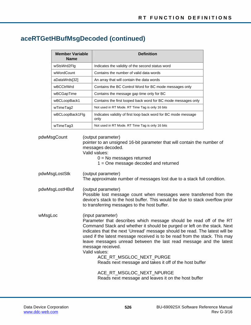
R T F U N C T I O N D E F I N I T I O N S
Data Device Corporation BU-69092SX Software Reference Manual www.ddc-web.com Rev G-3/16
526
aceRTGetHBufMsgDecoded (continued)
Member Variable Name
Definition
wStsWrd2Flg Indicates the validity of the second status word
wWordCount Contains the number of valid data words
aDataWrds[32] An array that will contain the data words
wBCCtrlWrd Contains the BC Control Word for BC mode messages only
wBCGapTime Contains the message gap time only for BC
wBCLoopBack1 Contains the first looped back word for BC mode messages only
wTimeTag2 Not used in RT Mode. RT Time Tag is only 16 bits
wBCLoopBack1Flg Indicates validity of first loop back word for BC mode message only
wTimeTag3 Not used in RT Mode. RT Time Tag is only 16 bits
pdwMsgCount (output parameter)
pointer to an unsigned 16-bit parameter that will contain the number of messages decoded.
Valid values: 0 = No messages returned 1 = One message decoded and returned pdwMsgLostStk (output parameter)
The approximate number of messages lost due to a stack full condition. pdwMsgLostHBuf (output parameter)
Possible lost message count when messages were transferred from the device’s stack to the host buffer. This would be due to stack overflow prior to transferring messages to the host buffer.
wMsgLoc (input parameter)
Parameter that describes which message should be read off of the RT Command Stack and whether it should be purged or left on the stack. Next indicates that the next ‘Unread’ message should be read. The latest will be used if the latest message received is to be read from the stack. This may leave messages unread between the last read message and the latest message received.
Valid values: ACE_RT_MSGLOC_NEXT_PURGE Reads next message and takes it off of the host buffer ACE_RT_MSGLOC_NEXT_NPURGE Reads next message and leaves it on the host buffer

R T F U N C T I O N D E F I N I T I O N S
Data Device Corporation BU-69092SX Software Reference Manual www.ddc-web.com Rev G-3/16
527
aceRTGetHBufMsgDecoded (continued) ACE_RT_MSGLOC_LATEST_PURGE Reads current message and takes it off of the host buffer ACE_RT_MSGLOC_LATEST_NPURGE Reads current message and leaves it on the host buffer
DESCRIPTION This function reads and decodes a message from the host buffer, if one is present, and places the decoded message into the formatted MSGSTRUCT structure. The function will get a raw message from the host buffer and then call the aceRTDecodeRawMsg() function to pass the formatted message to the pMsg parameter.
RETURN VALUE ACE_ERR_SUCCESS The function completed successfully ACE_ERR_INVALID_DEVNUM An invalid device number was input by the user ACE_ERR_INVALID_STATE The device is not in a Ready or Run state ACE_ERR_INVALID_MODE The device is not in RT or RTMT mode ACE_ERR_PARAMETER The pdwMsgLostHBuf parameter and/or the
pdwMsgLostStk parameter is Null ACE_ERR_MT_MSGLOC The wMsgLoc input parameter is greater than three
EXAMPLE S16BIT DevNum = 0; U16BIT wMsgLoc = ACE_RT_MSGLOC_NEXT_PURGE; U32BIT pdwMsgCount, pdwMsgLostStk, pdwMsgLostHBuf; MSGSTRUCT pMsg; /* Read the next message from the Hbuf, and purge when completed */ nResult = aceRTGetHBufMsgDecoded(S16BIT DevNum, &pMsg, &pdwMsgCount, &pdwMsgLostStk, &pdwMsgLostHBuf, wMsgLoc); if(nResult) { printf(“Error in aceRTGetHBufMsgDecoded() function \n”); PrintOutError(nResult); return; } else { printf(“Messages Read = %d, messages lost (buf) = %d, messages lost (HBuf) = %d\n, pdwMsgCount, pdwMsgLostStk, pdwMsgLostHBuf); }
R T F U N C T I O N D E F I N I T I O N S
Data Device Corporation BU-69092SX Software Reference Manual www.ddc-web.com Rev G-3/16
528
aceRTGetHBufMsgDecoded (continued) SEE ALSO
aceRTStkToHBuf() aceRTGetHBufMsgCount() aceRTGetHBufMsgsRaw()

R T F U N C T I O N D E F I N I T I O N S
Data Device Corporation BU-69092SX Software Reference Manual www.ddc-web.com Rev G-3/16
529
aceRTGetHBufMsgsRaw This function will read raw messages from the host buffer.
PROTOTYPE #include “Rt.h” S16BIT _DECL aceRTGetHBufMsgsRaw(S16BIT DevNum, U16BIT *pBuffer, U16BIT wBufferSize, U32BIT *pdwMsgCount, U32BIT *pdwMsgLostStk, U32BIT *pdwMsgLostHBuf);
HARDWARE EMACE, E²MA, AceXtreme
STATE Ready, Run
MODE RT, RTMT, RTMT-I
PARAMETERS DevNum (input parameter) Logical Device Number Valid values: 0 – 31 pBuffer (output parameter)
Pointer to an unsigned 16-bit word buffer that will contain the raw messages read from the host buffer.
wBufferSize (input parameter) Size of buffer in 16-bit words Valid value:
There is no requirement for size of the buffer as there is for the host buffer, but it is a more efficient use of resources if the buffer size is a multiple of ACE_MSGSIZE_RT. For example, if it is desired to copy 10 messages at a time from the host buffer to the user buffer, the user buffer size would be ACE_MSGSIZE_RT * 10.
pdwMsgCount (output parameter)
Pointer to an unsigned 32-bit double word to contain the message count read from the host buffer.

R T F U N C T I O N D E F I N I T I O N S
Data Device Corporation BU-69092SX Software Reference Manual www.ddc-web.com Rev G-3/16
530
aceRTGetHBufMsgsRaw (continued) pdwMsgLostStk (output parameter)
Pointer to an unsigned 32-bit double word that contains the approximate number of messages lost due to a stack full condition.
pdwMsgLostHBuf (output parameter)
Pointer to an unsigned 32-bit double word that contains the possible lost message count when messages were transferred from the device’s stack to the host buffer. This would be due to a stack overflow prior to transferring messages to the host buffer.
DESCRIPTION This function reads as many messages as possible off of the host buffer. If no errors occur, the number of messages read will be returned. The limiting factor when copying messages to the local buffer is the local buffer size and the number of messages available on the host buffer.
Note: Each message is a fixed length of ACE_MSGSIZE_RT words. This macro should be used when creating the host buffer as the size of this structure is subject to change based on the version of the SDK.
Note: This function will still return ACE_ERR_SUCCESS if there were no messages to read. If this is the case, the pdwMsgCount parameter will point to a value of zero.
RETURN VALUE ACE_ERR_SUCCESS The function completed successfully ACE_ERR_INVALID_DEVNUM An invalid device number was input by the user ACE_ERR_INVALID_STATE The device is not in a Ready or Run state ACE_ERR_INVALID_MODE The device is not in RT or RTMT mode ACE_ERR_PARAMETER The pdwMsgLostHBuf parameter and/or the
pdwMsgLostStk parameter is Null ACE_ERR_INVALID_BUF The pBuffer parameter is Null and/or the
wBufferSize parameter is less than ACE_MSGSIZE_RT
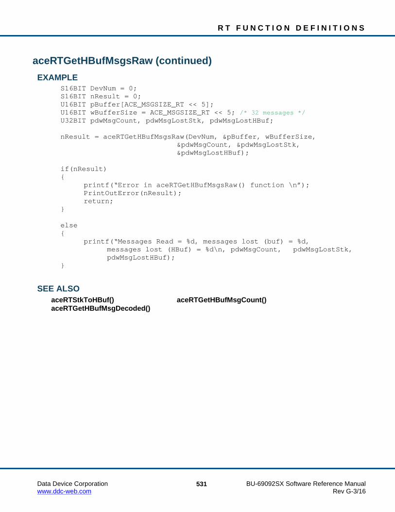
R T F U N C T I O N D E F I N I T I O N S
Data Device Corporation BU-69092SX Software Reference Manual www.ddc-web.com Rev G-3/16
531
aceRTGetHBufMsgsRaw (continued) EXAMPLE
S16BIT DevNum = 0; S16BIT nResult = 0; U16BIT pBuffer[ACE_MSGSIZE_RT << 5]; U16BIT wBufferSize = ACE_MSGSIZE_RT << 5; /* 32 messages */ U32BIT pdwMsgCount, pdwMsgLostStk, pdwMsgLostHBuf; nResult = aceRTGetHBufMsgsRaw(DevNum, &pBuffer, wBufferSize, &pdwMsgCount, &pdwMsgLostStk, &pdwMsgLostHBuf); if(nResult) { printf(“Error in aceRTGetHBufMsgsRaw() function \n”); PrintOutError(nResult); return; } else { printf(“Messages Read = %d, messages lost (buf) = %d, messages lost (HBuf) = %d\n, pdwMsgCount, pdwMsgLostStk, pdwMsgLostHBuf); }
SEE ALSO aceRTStkToHBuf() aceRTGetHBufMsgCount() aceRTGetHBufMsgDecoded()

R T F U N C T I O N D E F I N I T I O N S
Data Device Corporation BU-69092SX Software Reference Manual www.ddc-web.com Rev G-3/16
532
aceRTGetStkMetric This function returns performance information about the RT Command Stack.
PROTOTYPE #include “rt.h” S16BIT _DECL aceMTGetHBufMetric(S16BIT DevNum, STKMETRIC *pMetric, U16BIT bReset);
HARDWARE EMACE, E²MA, AceXtreme
STATE Ready, Run
MODE RT, RTMT, RTMT-I
PARAMETERS DevNum (input parameter) Logical Device Number Valid values: 0 – 31 pMetric (output parameter)
Pointer to a STKMETRIC structure to be filled in with metrics. The STKMETRIC structure contains the following members: dwLost, dwPctFull, and dwHighPct. The dwLost member parameter contains the total number of messages lost on the hardware stack. The dwPctFull parameter contains the percentage of the stack used at one snapshot in time. The dwHighPct parameter contains the highest percentage of the stack used over an extended period of time.
bReset (input parameter)
This will specify if the highest percentage value should be reset after this function returns.
Valid values: FALSE (0) Do not reset the highest percentage value TRUE (1) Reset the highest percentage value

R T F U N C T I O N D E F I N I T I O N S
Data Device Corporation BU-69092SX Software Reference Manual www.ddc-web.com Rev G-3/16
533
aceRTGetStkMetric (continued) DESCRIPTION
This function returns performance information about the RT Command Stack that is also referred to as the RT Descriptor Stack. Built-in test metrics can report the number of messages in the host buffer, the total number of messages lost since the host buffer was installed, the current percentage of the host buffer that is used, and the highest percentage of the host buffer used since it was installed. In order to use this function, a call to aceRTGetStkMsgDecoded() must be made to read the stack with the NPURGE option.
RETURN VALUE ACE_ERR_SUCCESS The function completed successfully ACE_ERR_INVALID_DEVNUM An invalid device number was input by the user ACE_ERR_INVALID_STATE The device is not in a Ready or Run state ACE_ERR_INVALID_MODE The device is not in RT or RTMT mode ACE_ERR_PARAMETER The pMetric pointer input by the user is NULL ACE_ERR_METRICS_NOT_ENA Metrics are not enabled and should be set by
calling the aceSetMetrics() function
EXAMPLE S16BIT DevNum = 0; STKMETRIC *pMetric; U16BIT bReset = 1; S16BIT nResult = 0; nResult = aceRTGetStkMetric(DevNum, pMetric, bReset) if(nResult) { printf(“Error in aceRTGetStkMetric() function \n”); PrintOutError(nResult); return; }
SEE ALSO aceSetMetrics() aceMTGetHBufMetric() aceRTGetHBufMetric() aceMTGetStkMetric()

R T F U N C T I O N D E F I N I T I O N S
Data Device Corporation BU-69092SX Software Reference Manual www.ddc-web.com Rev G-3/16
534
aceRTGetStkMsgDecoded This function reads raw messages off of the RT command stack and decodes them into a message structure so that they can be easily read and viewed.
PROTOTYPE #include “Rt.h” S16BIT _DECL aceRTGetStkMsgDecoded(S16BIT DevNum, MSGSTRUCT *pMsg, U16BIT wMsgLoc);
HARDWARE EMACE, E²MA, AceXtreme
STATE Ready, Run
MODE RT, RTMT, RTMT-I
PARAMETERS DevNum (input parameter) Logical Device Number Valid values: 0 – 31 pMsg (output parameter)
Pointer to a MSGSTRUCT parameter that will return the decoded message. The table below lists all member variables that exist in the MSGSTRUCT structure along with their definition.
Member Variable
Name Definition
wBlkSts Contains the block status word of the message
wTimeTag Contains the time tag of the message
wCmdWrd1 Contains the command word
wCmdWrd2 Contains the second command word for RT to RT transfers
wCmdWrd1Flg Indicates the validity of the first command word
wCmdWrd2Flg Indicates the validity of the second command word
wStsWrd1 Contains first status word
wStsWrd2 Contains second status word
wStsWrd1Flg Indicates the validity of the first status word
wStsWrd2Flg Indicates the validity of the second status word
wWordCount Contains the number of valid data words
aDataWrds[32] An array that will contain the data words

R T F U N C T I O N D E F I N I T I O N S
Data Device Corporation BU-69092SX Software Reference Manual www.ddc-web.com Rev G-3/16
535
aceRTGetStkMsgDecoded (continued)
Member Variable Name
Definition
wBCCtrlWrd Contains the BC Control Word for BC mode messages only
wBCGapTime Contains the message gap time only for BC
wBCLoopBack1 Contains the first looped back word for BC mode messages only
wTimeTag2 Not used in RT Mode. RT Time Tag is only 16 bits
wBCLoopBack1Flg Indicates validity of first loop back word for BC mode message only
wTimeTag3 Not used in RT Mode. RT Time Tag is only 16 bits
wMsgLoc (input parameter)
Parameter that describes which message should be read off of the RT Command Stack and whether it should be purged or left on the stack. Next indicates that the next ‘Unread’ message should be read. Latest will be used if the latest message received is to be read from the stack. This may leave messages unread between the last read message and the latest message received.
Valid values: ACE_RT_MSGLOC_NEXT_PURGE Reads next message and takes it off of the stack ACE_RT_MSGLOC_NEXT_NPURGE Reads next message and leaves it on the stack (not supported with
AceXtreme Devices) ACE_RT_MSGLOC_LATEST_PURGE Reads current message and takes it off of the stack ACE_RT_MSGLOC_LATEST_NPURGE Reads current message and leaves it on the stack (not supported
with AceXtreme Devices)
DESCRIPTION This function reads either the next unread message or the latest message received on the RT Command Stack. It decodes the message by placing all the info into a MSGSTRUCT by calling the aceRTDecodeRawMsg() function. After reading the message, the user may have this routine purge the message from the RT stack or leave it in place.

R T F U N C T I O N D E F I N I T I O N S
Data Device Corporation BU-69092SX Software Reference Manual www.ddc-web.com Rev G-3/16
536
aceRTGetStkMsgDecoded (continued) RETURN VALUE
S16BIT nResult 1 if message read, 0 if no message read ACE_ERR_INVALID_DEVNUM An invalid device number was input by the user ACE_ERR_INVALID_STATE The device is not in a Ready or Run state ACE_ERR_INVALID_MODE The device is not in RT or RTMT mode ACE_ERR_MSGSTRUCT The pMsg parameter is Null ACE_ERR_PARAMETER The wMsgLoc input parameter is greater than three
EXAMPLE S16BIT DevNum = 0; S16BIT nResult = 0; U16BIT wMsgLoc; MSGSTRUCT pMsg; nResult = aceRTGetStkMsgDecoded(DevNum, &pMsg, wMsgLoc); if(nResult < 0) { printf(“Error in aceRTGetStkMsgDecoded() function \n”); PrintOutError(nResult); return; } else { printf(“Number of Messages returned = %d\n”, nResult); }
SEE ALSO aceRTDecodeRawMsg() aceRTGetStkMsgsRaw() aceRTGetHBufMsgsRaw() aceRTGetHBufMsgDecoded()

R T F U N C T I O N D E F I N I T I O N S
Data Device Corporation BU-69092SX Software Reference Manual www.ddc-web.com Rev G-3/16
537
aceRTGetStkMsgsRaw This function reads raw messages off of the RT command stack.
PROTOTYPE #include “Rt.h” S16BIT _DECL aceRTGetStkMsgsRaw(S16BIT DevNum, U16BIT *pBuffer, U16BIT wBufferSize);
HARDWARE EMACE, E²MA, AceXtreme
STATE Ready, Run
MODE RT, RTMT, RTMT-I
PARAMETERS DevNum (input parameter) Logical Device Number Valid values: 0 – 31 pBuffer (output parameter)
Pointer to an unsigned 16-bit buffer that will be used to return the raw RT Stack Messages. Each message is a fixed length of ACE_MSGSIZE_RT words in length.
wBufferSize (input parameter)
This is the size in words of the unsigned 16-bit word buffer that will contain the returned raw messages from the RT command stack. The most efficient size for this buffer is calculated as ACE_MSGSIZE_RT. This value represents the maximum number of words to be read.
DESCRIPTION This function reads as many messages as possible off of the RT command stack. If no errors occur, the amount of messages will be returned. The limiting factor when copying messages to the buffer is the buffer size and the number of messages available on the stack.
Note: Each message is a fixed length of ACE_MSGSIZE_RT words.

R T F U N C T I O N D E F I N I T I O N S
Data Device Corporation BU-69092SX Software Reference Manual www.ddc-web.com Rev G-3/16
538
aceRTGetStkMsgsRaw (continued) RETURN VALUE
S16BIT nResult This represents the number of messages transferred to the buffer
ACE_ERR_INVALID_DEVNUM An invalid device number was input by the user ACE_ERR_INVALID_STATE The device is not in a Ready or Run state ACE_ERR_INVALID_MODE The device is not in RT or RTMT mode ACE_ERR_INVALID_BUF The pBuffer parameter is Null and/or the
wBufferSize input parameter is less than ACE_MSGSIZE_RT
EXAMPLE S16BIT DevNum = 0; S16BIT nResult = 0; U16BIT pBuffer[ACE_MSGSIZE_RT << 8]; /* 256 messages */ U16BIT wBufferSize = ACE_MSGSIZE_RT << 8; nResult = aceRTGetStkMsgsRaw(DevNum, pBuffer, wBufferSize); if(nResult < 0) { printf(“Error in aceRTGetStkMsgsRaw() function \n”); PrintOutError(nResult); return; } else { printf(“Number of Raw Messages returned = %d\n”, nResult); }
SEE ALSO aceRTDecodeRawMsg() aceRTGetStkMsgDecoded() aceRTGetHBufMsgsRaw() aceRTGetHBufMsgDecoded()

R T F U N C T I O N D E F I N I T I O N S
Data Device Corporation BU-69092SX Software Reference Manual www.ddc-web.com Rev G-3/16
539
aceRTInstallHBuf This function will allocate a host buffer.
PROTOTYPE #include “Rt.h” S16BIT _DECL aceRTInstallHBuf(S16BIT DevNum, U32BIT dwHBufSize);
HARDWARE EMACE, E²MA, AceXtreme
STATE Ready
MODE RT, RTMT, RTMT-I
PARAMETERS DevNum (input parameter) Logical Device Number Valid values: 0 – 31 dwHBufSize (input parameter)
Size of the desired host buffer in 16-bit words. Refer to description for size restrictions.
Valid values: [(RT command stack size/4)*ACE_MSGSIZE_RT*3] to 5,120,000
words
DESCRIPTION This function allocates a host buffer based on the size parameter. For this function to succeed the size must be at least 3 times greater than the number of messages that can be stored in the command stacks multiplied by ACE_MSGSIZE_RT (fixed length RT msgs). The size of the host buffer cannot exceed 5000K. Example: if the command stack is defined as 256 words then the dwHBufSize input parameter must be at least: (256/4) * ACE_MSGSIZE_RT * 3 = 6912 words. 256 = length of command stack 256/4 = number of messages that can be stored in the command stack ACE_MSGSIZE_RT = 36 words
Note: The dwHBufSize parameter is in words. The macro ACE_MSGSIZE_RT should be used as it may change in future configurations.

R T F U N C T I O N D E F I N I T I O N S
Data Device Corporation BU-69092SX Software Reference Manual www.ddc-web.com Rev G-3/16
540
aceRTInstallHBuf (continued) If the host buffer has already been allocated, this function will call the aceRTUninstallHBuf() function to uninstall it and then install it again based on the dwHBufSize input parameter.
RETURN VALUE ACE_ERR_SUCCESS The function completed successfully ACE_ERR_INVALID_DEVNUM An invalid device number was input by the user ACE_ERR_INVALID_STATE The device is not in a Ready state ACE_ERR_INVALID_MODE The device is not in RT or RTMT mode ACE_ERR_MT_HBUFSIZE The dwHBufSize input parameter is too small ACE_ERR_RT_HBUF The proper memory for the host buffer could not be
allocated ACE_WRN_RT_CFG_INVALID Operation of your device may be problematic
because one or more of the following interrupts have been enabled: Time Tag Rollover, RT Address Parity Error, and/or Ram Parity Error along with the Interrupt Status Queue. See Appendix B for details.
EXAMPLE S16BIT DevNum = 0; S16BIT nResult = 0; U32BIT dwHBufSize = ((256/4) * ACE_MSGSIZE_RT * 3); // create a host buffer that can be used with a stack size of 256 words nResult = aceRTInstallHBuf(DevNum, dwHBufSize); if(nResult) { printf(“Error in aceRTInstallHBuf() function \n”); PrintOutError(nResult); return; }
SEE ALSO aceRTUninstallHBuf()

R T F U N C T I O N D E F I N I T I O N S
Data Device Corporation BU-69092SX Software Reference Manual www.ddc-web.com Rev G-3/16
541
aceRTModeCodeIrqDisable This function will disable mode code interrupts.
PROTOTYPE #include “Rt.h” S16BIT _DECL aceRTModeCodeIrqDisable(S16BIT DevNum, U16BIT wModeCodeType, U16BIT wModeCodeIrq);
HARDWARE EMACE, E²MA, AceXtreme
STATE Ready, Run
MODE RT, RTMT, RTMT-I
PARAMETERS DevNum (input parameter) Logical Device Number Valid values: 0 – 31 wModeCodeType (input parameter)
An unsigned 16-bit parameter describing the mode code type. The type is a combination of Receive/Transmit, with/without data, and Broadcast. Please refer to the aceRTModeCodeIrqEnable() function for valid values.
wModeCodeIrq (input parameter)
An unsigned 16-bit parameter that indicates which mode codes to disable. This value is an OR’ed combination of the following values. Please refer to the aceRTModeCodeIrqEnable() function for valid values.
DESCRIPTION This function will disable the hardware from interrupting the host based on the reception of certain mode codes. The mode codes are specified by their type and their command.
RETURN VALUE ACE_ERR_SUCCESS The function completed successfully ACE_ERR_INVALID_DEVNUM An invalid device number was input by the user ACE_ERR_INVALID_STATE The device is not in a Ready or Run state ACE_ERR_INVALID_MODE The device is not in RT or RTMT mode ACE_ERR_PARAMETER The wModeCodeType input parameter contains a
value greater than seven
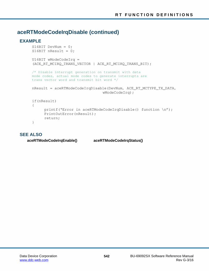
R T F U N C T I O N D E F I N I T I O N S
Data Device Corporation BU-69092SX Software Reference Manual www.ddc-web.com Rev G-3/16
542
aceRTModeCodeIrqDisable (continued) EXAMPLE
S16BIT DevNum = 0; S16BIT nResult = 0; U16BIT wModeCodeIrq = (ACE_RT_MCIRQ_TRANS_VECTOR | ACE_RT_MCIRQ_TRANS_BIT); /* Disable interrupt generation on transmit with data mode codes, actual mode codes to generate interrupts are trans vector word and transmit bit word */ nResult = aceRTModeCodeIrqDisable(DevNum, ACE_RT_MCTYPE_TX_DATA, wModeCodeIrq); if(nResult) { printf(“Error in aceRTModeCodeIrqDisable() function \n”); PrintOutError(nResult); return; }
SEE ALSO aceRTModeCodeIrqEnable() aceRTModeCodeIrqStatus()

R T F U N C T I O N D E F I N I T I O N S
Data Device Corporation BU-69092SX Software Reference Manual www.ddc-web.com Rev G-3/16
543
aceRTModeCodeIrqEnable This function will cause an interrupt on a received mode code.
PROTOTYPE #include “Rt.h” S16BIT _DECL aceRTModeCodeIrqEnable(S16BIT DevNum, U16BIT wModeCodeType, U16BIT wModeCodeIrq);
HARDWARE EMACE, E²MA, AceXtreme
STATE Ready, Run
MODE RT, RTMT, RTMT-I
PARAMETERS DevNum (input parameter) Logical Device Number Valid values: 0 – 31 wModeCodeType (input parameter)
An unsigned 16-bit parameter describing the mode code type. The type is a combination of Receive/Transmit, with/without data, and Broadcast. The type value may be any one of the following.
Valid values: ACE_RT_MCTYPE_RX_NO_DATA Receive mode codes without data ACE_RT_MCTYPE_RX_DATA Receive mode codes with data ACE_RT_MCTYPE_TX_NO_DATA Transmit mode codes without data ACE_RT_MCTYPE_TX_DATA Transmit mode codes with data ACE_RT_MCTYPE_BCST_RX_NO_DATA Broadcast receive mode codes without data ACE_RT_MCTYPE_BCST_RX_DATA Broadcast receive mode codes with data

R T F U N C T I O N D E F I N I T I O N S
Data Device Corporation BU-69092SX Software Reference Manual www.ddc-web.com Rev G-3/16
544
aceRTModeCodeIrqEnable (continued) ACE_RT_MCTYPE_BCST_TX_NO_DATA Broadcast transmit mode codes without data ACE_RT_MCTYPE_BCST_TX_DATA Broadcast transmit mode codes with data wModeCodeIrq (input parameter)
An unsigned 16-bit parameter that indicates which mode codes will generate the interrupt. This value is an OR’ed combination of the following values. The qualifying types are listed in italics.
Valid values: ACE_RT_MCIRQ_DYN_BUS_CTRL TX_NO_DATA ACE_RT_MCIRQ_SYNCHRONIZE (BCST_)(TX|RX)(_NO|)_DATA ACE_RT_MCIRQ_TX_STATUS_WRD TX_NO_DATA ACE_RT_MCIRQ_INIT_SELF_TEST (BCST_)TX_NO_DATA ACE_RT_MCIRQ_TRNS_SHUTDOWN (BCST_)TX_NO_DATA ACE_RT_MCIRQ_OVRD_TRNS_SHUTDOWN (BCST_)TX_NO_DATA ACE_RT_MCIRQ_INH_TERM_FLAG (BCST_)TX_NO_DATA ACE_RT_MCIRQ_OVR_INH_TERM_FLG (BCST_)TX_NO_DATA ACE_RT_MCIRQ_RESET_REMOTE_TERM
(BCST_)TX_NO_DATA ACE_RT_MCIRQ_TRNS_VECTOR TX_DATA ACE_RT_MCIRQ_TRNS_LAST_CMD TX_DATA ACE_RT_MCIRQ_TRNS_BIT_WRD TX_DATA ACE_RT_MCIRQ_SEL_TRNS_SHUTDWN (BCST_)RX_DATA

R T F U N C T I O N D E F I N I T I O N S
Data Device Corporation BU-69092SX Software Reference Manual www.ddc-web.com Rev G-3/16
545
aceRTModeCodeIrqEnable (continued) ACE_RT_MCIRQ_OVRD_SEL_TRNS_SHUTDWN
(BCST_)RX_DATA ACE_RT_MCIRQ_RESERVED_BIT6 ACE_RT_MCIRQ_RESERVED_BIT7 ACE_RT_MCIRQ_RESERVED_BIT8 ACE_RT_MCIRQ_RESERVED_BIT9 ACE_RT_MCIRQ_RESERVED_BIT10 ACE_RT_MCIRQ_RESERVED_BIT11 ACE_RT_MCIRQ_RESERVED_BIT12 ACE_RT_MCIRQ_RESERVED_BIT13 ACE_RT_MCIRQ_RESERVED_BIT14 ACE_RT_MCIRQ_RESERVED_BIT15
DESCRIPTION This function will set the hardware to interrupt the host processor based on reception of selected mode codes. The mode codes are specified by their type and their command.
RETURN VALUE ACE_ERR_SUCCESS The function completed successfully ACE_ERR_INVALID_DEVNUM An invalid device number was input by the user ACE_ERR_INVALID_STATE The device is not in a Ready or Run state ACE_ERR_INVALID_MODE The device is not in RT or RTMT mode ACE_ERR_PARAMETER The wModeCodeType input parameter contains a
value greater than seven

R T F U N C T I O N D E F I N I T I O N S
Data Device Corporation BU-69092SX Software Reference Manual www.ddc-web.com Rev G-3/16
546
aceRTModeCodeIrqEnable (continued) EXAMPLE
S16BIT DevNum = 0; S16BIT nResult = 0; U16BIT wModeCodeIrq = (ACE_RT_MCIRQ_TRNS_VECTOR|ACE_RT_MCIRQ_TRNS_BIT); /* generate interrupt on transmit with data mode code actual mode code to generate interrupts are transmit vector word and transmit bit word */ nResult = aceRTModeCodeIrqEnable(DevNum, ACE_RT_MCTYPE_TX_DATA, wModeCodeIrq); if(nResult) { printf(“Error in aceRTModeCodeIrqEnable() function \n”); PrintOutError(nResult); return; }
SEE ALSO aceRTModeCodeIrqDisable() aceRTModeCodeIrqStatus()

R T F U N C T I O N D E F I N I T I O N S
Data Device Corporation BU-69092SX Software Reference Manual www.ddc-web.com Rev G-3/16
547
aceRTModeCodeIrqStatus This function will return the status of a mode code generating an interrupt.
PROTOTYPE #include “Rt.h” S16BIT _DECL aceRTModeCodeIrqStatus(S16BIT DevNum, U16BIT wModeCodeType, U16BIT *pwMCIrqStatus);
HARDWARE EMACE, E²MA, AceXtreme
STATE Ready, Run
MODE RT, RTMT, RTMT-I
PARAMETERS DevNum (input parameter) Logical Device Number Valid values: 0 – 31 wModeCodeType (input parameter)
An unsigned 16-bit parameter describing the mode code type. The type is a combination of Receive/Transmit, with/without data, and Broadcast. The type value may be any one of the following. Please refer to the aceRTModeCodeIrqEnable() for valid values.
pwMCIrqStatus (output parameter)
Pointer to an unsigned 16-bit parameter, which will receive the mode codes that will generate an interrupt. This is a bit packed value that represents the OR’ed combination of mode codes as specified in aceRTModeCodeIrqEnable().
DESCRIPTION This function will return information regarding the status of a mode code generating an interrupt by reading one of the Mode Code Interrupt Lookup locations.
RETURN VALUE ACE_ERR_SUCCESS The function completed successfully ACE_ERR_INVALID_DEVNUM An invalid device number was input by the user ACE_ERR_INVALID_STATE The device is not in a Ready or Run state ACE_ERR_INVALID_MODE The device is not in RT or RTMT mode

R T F U N C T I O N D E F I N I T I O N S
Data Device Corporation BU-69092SX Software Reference Manual www.ddc-web.com Rev G-3/16
548
aceRTModeCodeIrqStatus (continued) ACE_ERR_PARAMETER The wModeCodeType input parameter contains a
value greater than seven and/or the pwMCIrqStatus is Null
EXAMPLE S16BIT DevNum = 0; S16BIT nResult = 0; U16BIT wModeCodeIrq; /* Get the status of which mode codes will generate interrupts given the mode code type to be. The value returned in wModeCodeIrq can be decoded by applying the defined macros for the different mode codes as defined in aceRTModeCodeIrqEnable() */ nResult = aceRTModeCodeIrqStatus(DevNum, ACE_RT_MCTYPE_TX_DATA, &wModeCodeIrq); if(nResult) { printf(“Error in aceRTModeCodeIrqStatus() function \n”); PrintOutError(nResult); return; }
SEE ALSO aceRTModeCodeIrqEnable() aceRTModeCodeIrqDisable()

R T F U N C T I O N D E F I N I T I O N S
Data Device Corporation BU-69092SX Software Reference Manual www.ddc-web.com Rev G-3/16
549
aceRTModeCodeReadData This function will read data from the Enhanced Mode Code Data Locations table.
PROTOTYPE #include “Rt.h” S16BIT _DECL aceRTModeCodeReadData(S16BIT DevNum, U16BIT wModeCode, U16BIT *pMCData);
HARDWARE EMACE, E²MA, AceXtreme
STATE Ready, Run
MODE RT, RTMT, RTMT-I
PARAMETERS DevNum (input parameter) Logical Device Number Valid values: 0 – 31 wModeCode (input parameter)
This parameter specifies which mode code contains the data that should be read.
Valid values: ACE_RT_MCDATA_RX_SYNCHRONIZE ACE_RT_MCDATA_RX_SEL_T_SHUTDWN ACE_RT_MCDATA_RX_OVR_SEL_T_SHUTDWN ACE_RT_MCDATA_TX_TRNS_VECTOR ACE_RT_MCDATA_TX_TRNS_LAST_CMD ACE_RT_MCDATA_TX_TRNS_BIT ACE_RT_MCDATA_BCST_SYNCHRONIZE ACE_RT_MCDATA_BCST_SEL_T_SHUTDWN ACE_RT_MCDATA_BCST_OVR_SEL_T_SHUTDWN pMCData (output parameter)
A single unsigned 16-bit piece of data returned from the Mode Code data table
DESCRIPTION This function will read data from the Mode Code data table. The mode code for which data is to be read is specified by wModeCode. The data returned will be a single U16BIT word that is read from the Mode Code data table.

R T F U N C T I O N D E F I N I T I O N S
Data Device Corporation BU-69092SX Software Reference Manual www.ddc-web.com Rev G-3/16
550
aceRTModeCodeReadData (continued) RETURN VALUE
ACE_ERR_SUCCESS The function completed successfully ACE_ERR_INVALID_DEVNUM An invalid device number was input by the user ACE_ERR_INVALID_STATE The device is not in a Ready or Run state ACE_ERR_INVALID_MODE The device is not in RT or RTMT mode ACE_ERR_PARAMETER The wModeCode input parameter contains a value
greater than 0x2F and/or the pMCData parameter is Null
EXAMPLE S16BIT DevNum = 0; S16BIT nResult = 0; U16BIT pMCData; /*Read the data that is associated with the ACE_RT_MCDATA_TX_TRNS_BIT mode code. */ nResult = aceRTModeCodeReadData(DevNum, ACE_RT_MCDATA_TX_TRNS_BIT, &pMCData); if(nResult) { printf(“Error in aceRTModeCodeReadData() function \n”); PrintOutError(nResult); return; }
SEE ALSO aceRTModeCodeWriteData()

R T F U N C T I O N D E F I N I T I O N S
Data Device Corporation BU-69092SX Software Reference Manual www.ddc-web.com Rev G-3/16
551
aceRTModeCodeWriteData This function will write to the Enhanced Mode Code Data Locations table.
PROTOTYPE #include “Rt.h” S16BIT _DECL aceRTModeCodeWriteData(S16BIT DevNum, U16BIT wModeCode, U16BIT wMCData);
HARDWARE EMACE, E²MA, AceXtreme
STATE Ready, Run
MODE RT, RTMT, RTMT-I
PARAMETERS DevNum (input parameter) Logical Device Number Valid values: 0 – 31 wModeCode (input parameter)
This parameter specifies which mode code contains the data that should be written.
Valid values: ACE_RT_MCDATA_RX_SYNCHRONIZE ACE_RT_MCDATA_RX_SEL_T_SHUTDWN ACE_RT_MCDATA_RX_OVR_SEL_T_SHUTDWN ACE_RT_MCDATA_TX_TRNS_VECTOR ACE_RT_MCDATA_TX_TRNS_LAST_CMD ACE_RT_MCDATA_TX_TRNS_BIT ACE_RT_MCDATA_BCST_SYNCHRONIZE ACE_RT_MCDATA_BCST_SEL_T_SHUTDWN ACE_RT_MCDATA_BCST_OVR_SEL_T_SHUTDWN wMCData (input parameter)
A single unsigned 16-bit piece of data to write into the Mode Code data table
DESCRIPTION This function will write data to the specified Mode Code data table. The mode code for which data is to be written is specified by wModeCode. The data written will be a single U16BIT word that is written to the Mode Code data table.

R T F U N C T I O N D E F I N I T I O N S
Data Device Corporation BU-69092SX Software Reference Manual www.ddc-web.com Rev G-3/16
552
aceRTModeCodeWriteData (continued) RETURN VALUE
ACE_ERR_SUCCESS The function completed successfully ACE_ERR_INVALID_DEVNUM An invalid device number was input by the user ACE_ERR_INVALID_STATE The device is not in a Ready or Run state ACE_ERR_INVALID_MODE The device is not in RT or RTMT mode ACE_ERR_PARAMETER The wModeCode parameter
EXAMPLE S16BIT DevNum = 0; U16BIT wMCData = 0x4DDC; /*Read the data that is associated with the ACE_RT_MCDATA_TX_TRNS_BIT mode code. */ nResult = aceRTModeCodeWriteData(DevNum, ACE_RT_MCDATA_TX_TRNS_BIT, wMCData); if(nResult) { printf(“Error in aceRTModeCodeWriteData() function \n”); PrintOutError(nResult); return; }
SEE ALSO aceRTModeCodeReadData()
R T F U N C T I O N D E F I N I T I O N S
Data Device Corporation BU-69092SX Software Reference Manual www.ddc-web.com Rev G-3/16
553
aceRTMsgLegalityDisable This function will illegalize a message for a subaddress.
PROTOTYPE #include “Rt.h” S16BIT _DECL aceRTMsgLegalityDisable(S16BIT DevNum, U16BIT wOwnAddrOrBcst, U16BIT wTR, U16BIT wSA, U32BIT dwWC_MCMask);
HARDWARE EMACE, E²MA, AceXtreme
STATE Ready, Run
MODE RT, RTMT, RTMT-I
PARAMETERS DevNum (input parameter) Logical Device Number Valid values: 0 – 31 wOwnAddrOrBcst (input parameter)
This parameter specifies whether the RT address is own or broadcast Valid values: ACE_RT_OWN_ADDRESS ACE_RT_BCST_ADDRSS ACE_RT_MODIFY_ALL wTR (input parameter) Specify the direction Transmit/Receive Valid values: 1 for transmit 0 for receive ACE_RT_MODIFY_ALL wSA (input parameter) Specify the subaddress to be illegalized Valid value: 0 - 31 ACE_RT_MODIFY_ALL

R T F U N C T I O N D E F I N I T I O N S
Data Device Corporation BU-69092SX Software Reference Manual www.ddc-web.com Rev G-3/16
554
aceRTMsgLegalityDisable (continued) dwWC_MCMask (input parameter) An unsigned 32-bit packed value that represents the 32 possible word
counts for the selected subaddress. Valid values: 0x00000000 – 0xFFFFFFFF Where the least significant bit = word count 0(32), and the most
significant bit = word count 31. (i.e. if the selected subaddress should be illegalized for word counts 1, 10, 16, 28 and 30 the dwWC_MCMask would equal 0x50010402)
DESCRIPTION This function will illegalize messages received by the RT. The selection is based on the following properties of the message: Broadcast/Own RT Address Transmit/Receive Subaddress Word count/Mode Code The ACE_RT_MODIFY_ALL can illegalize all messages of a certain type for all subaddresses.
RETURN VALUE ACE_ERR_SUCCESS The function completed successfully ACE_ERR_INVALID_DEVNUM An invalid device number was input by the user ACE_ERR_INVALID_STATE The device is not in a Ready or Run state ACE_ERR_INVALID_MODE The device is not in RT or RTMT mode ACE_ERR_PARAMETER The wOwnAddrOrBcst, wTR, and/or wSA
parameter(s) contain an incorrect input value

R T F U N C T I O N D E F I N I T I O N S
Data Device Corporation BU-69092SX Software Reference Manual www.ddc-web.com Rev G-3/16
555
aceRTMsgLegalityDisable (continued) EXAMPLE
S16BIT DevNum = 0; S16BIT nResult = 0; U32BIT dwWC_MCMask = 0x50044202; /* illegalize all subaddresses of RT address 5 for word counts of 30, 28, 18, 14, 9 and 1 */ nResult = aceRTMsgLegalityDisable(DevNum, 1, 1, ACE_RT_MODIFY_ALL, dwWC_MCMask); if(nResult) { printf(“Error in aceRTMsgLegalityDisable() function \n”); PrintOutError(nResult); return; }
SEE ALSO aceRTMsgLegalityEnable() aceRTMsgLegalityStatus()

R T F U N C T I O N D E F I N I T I O N S
Data Device Corporation BU-69092SX Software Reference Manual www.ddc-web.com Rev G-3/16
556
aceRTMsgLegalityEnable This function will legalize a message for a subaddress.
PROTOTYPE #include “Rt.h” S16BIT _DECL aceRTMsgLegalityEnable(S16BIT DevNum, U16BIT wOwnAddrOrBcst, U16BIT wTR, U16BIT wSA, U32BIT dwWC_MCMask);
HARDWARE EMACE, E²MA, AceXtreme
STATE Ready, Run
MODE RT, RTMT, RTMT-I
PARAMETERS DevNum (input parameter) Logical Device Number Valid values: 0 – 31 wOwnAddrOrBcst (input parameter)
This parameter specifies whether the RT address is own or broadcast Valid values: ACE_RT_OWN_ADDRESS ACE_RT_BCST_ADDRSS ACE_RT_MODIFY_ALL wTR (input parameter) Specify the direction Transmit/Receive Valid values: 1 for transmit 0 for receive ACE_RT_MODIFY_ALL wSA (input parameter)
Specify the subaddress to be legalized. OR’ed combination of the following values.
Valid values: 0-31 ACE_RT_MODIFY_ALL

R T F U N C T I O N D E F I N I T I O N S
Data Device Corporation BU-69092SX Software Reference Manual www.ddc-web.com Rev G-3/16
557
aceRTMsgLegalityEnable (continued) dwWC_MCMask (input parameter)
U32BIT bit packed value that represents the 32 possible word counts for the selected subaddress.
Valid values: 0x00000000 – 0xFFFFFFFF Where the least significant bit = word count 0(32), and the most
significant bit = word count 31. (i.e. if the selected subaddress should be legalized for word counts 1, 10, 16, 28 and 30 the dwWC_MCMask would equal 0x50010402)
DESCRIPTION This function will legalize messages received by the RT. The legalization is based on whether the message is Broadcast or to the RTs own address. Additionally, legality of the message is based on transmit or receive, the specific subaddress, and the word count (mode code) of the message. The ACE_RT_MODIFY_ALL can legalize all messages of a certain type on all subaddresses. The aceRTDataBlkMapToSA() function calls this function to legalize broadcast, transmit, and receive messages.
RETURN VALUE ACE_ERR_SUCCESS The function completed successfully ACE_ERR_INVALID_DEVNUM An invalid device number was input by the user ACE_ERR_INVALID_STATE The device is not in a Ready or Run state ACE_ERR_INVALID_MODE The device is not in RT or RTMT mode ACE_ERR_PARAMETER The wOwnAddrOrBcst, wTR, and/or wSA
parameter(s) contain an incorrect input value
EXAMPLE S16BIT DevNum = 0; S16BIT nResult = 0; U16BIT wOwnAddrOrBcst = 1, wTR = 1; U32BIT dwWC_MCMask = 0x50044202; /* legalize all subaddresses of RT address 5 for word counts of 30, 28, 18, 14, 9 and 1 */ nResult = aceRTMsgLegalityEnable(DevNum, wOwnAddrOrBcst, wTR, ACE_RT_MODIFY_ALL, dwWC_MCMask); if(nResult) { printf(“Error in aceRTMsgLegalityEnable() function \n”); PrintOutError(nResult); return; }
SEE ALSO aceRTMsgLegalityDisable() aceRTMsgLegalityStatus()

R T F U N C T I O N D E F I N I T I O N S
Data Device Corporation BU-69092SX Software Reference Manual www.ddc-web.com Rev G-3/16
558
aceRTMsgLegalityStatus This function will report the status of a particular command’s legality for a subaddress.
PROTOTYPE #include “Rt.h” S16BIT _DECL aceRTMsgLegalityStatus(S16BIT DevNum, U16BIT wOwnAddrOrBcst, U16BIT wTR, U16BIT wSA, U32BIT *pdwWC_MCMask);
HARDWARE EMACE, E²MA, AceXtreme
STATE Ready, Run
MODE RT, RTMT, RTMT-I
PARAMETERS DevNum (input parameter) Logical Device Number Valid values: 0 – 31 wOwnAddrOrBcst (input parameter) This parameter specifies whether the RT address is own or broadcast Valid values: ACE_RT_OWN_ADDRESS ACE_RT_BCST_ADDRSS wTR (input parameter) Specify the direction Transmit/Receive Valid values: 1 for transmit 0 for receive wSA (input parameter)
Specify the subaddress to check its particular command’s legality status Valid value: 0 -31

R T F U N C T I O N D E F I N I T I O N S
Data Device Corporation BU-69092SX Software Reference Manual www.ddc-web.com Rev G-3/16
559
aceRTMsgLegalityStatus (continued) dwWC_MCMask (output parameter) Pointer to an unsigned 32-bit packed value that represents the 32 possible word counts for the selected subaddress. ‘1’ = illegal Valid values: 0x00000000 – 0xFFFFFFFF Where the least significant bit = word count 0(32), and the most
significant bit = word count 31. (e.g. if the selected subaddress should be illegalized for word counts 1, 10, 16, 28 and 30 the dwWC_MCMask would equal 0x50010402)
DESCRIPTION This function reads the Command illegalizing table and reports the status of a particular command’s legality for a particular RT subaddress. The selection is based on the following properties of the message: Broadcast/Own RT Address Transmit/Receive Subaddress Word count/Mode Code
RETURN VALUE ACE_ERR_SUCCESS The function completed successfully ACE_ERR_INVALID_DEVNUM An invalid device number was input by the user ACE_ERR_INVALID_STATE The device is not in a Ready or Run state ACE_ERR_INVALID_MODE The device is not in RT or RTMT mode ACE_ERR_PARAMETER The wOwnAddrOrBcst, wTR, and/or wSA
parameter(s) contain an incorrect input value
EXAMPLE S16BIT DevNum = 0; S16BIT nResult = 0; U16BIT wOwnAddrOrBcst = 1, wTR = 1; U16BIT wSA = 12; U32BIT dwWC_MCMask = 0x50044202; // get the legalize status for subaddresses 12 of RT address 5 nResult = aceRTMsgLegalityStatus(DevNum, wOwnAddrOrBcst,wTR, wSA, &dwWC_MCMask); if(nResult) { printf(“Error in aceRTMsgLegalityStatus() function \n”); PrintOutError(nResult); return; }

R T F U N C T I O N D E F I N I T I O N S
Data Device Corporation BU-69092SX Software Reference Manual www.ddc-web.com Rev G-3/16
560
aceRTMsgLegalityStatus (continued) SEE ALSO
aceRTMsgLegalityDisable() aceRTMsgLegalityEnable()

R T F U N C T I O N D E F I N I T I O N S
Data Device Corporation BU-69092SX Software Reference Manual www.ddc-web.com Rev G-3/16
561
aceRTRelatchAddr This function latches the RT address that is currently being input to the device.
PROTOTYPE #include “Rt.h” S16BIT _DECL aceRTRelatchAddr(S16BIT DevNum);
HARDWARE EMACE, E²MA, AceXtreme
STATE Ready
MODE RT, RTMT, RTMT-I
PARAMETERS DevNum (input parameter) Logical Device Number Valid values: 0 – 31
DESCRIPTION This function latches the current RT address that is being input on the device. This function only applies to devices that have the capability to modify the RT address through external inputs. Some of the cards manufactured by DDC do not support this function. Please see your specific card manual to see if your card can set the RT address through external means and not just by software control.
RETURN VALUE ACE_ERR_SUCCESS The function completed successfully ACE_ERR_INVALID_DEVNUM An invalid device number was input by the user ACE_ERR_INVALID_STATE The device is not in a Ready state ACE_ERR_INVALID_MODE The device is not in RT or RTMT mode

R T F U N C T I O N D E F I N I T I O N S
Data Device Corporation BU-69092SX Software Reference Manual www.ddc-web.com Rev G-3/16
562
aceRTRelatchAddr (continued) EXAMPLE
S16BIT DevNum = 0; S16BIT nResult = 0; U16BIT wRTAddress = 10; // set logical device number to RT address 10 nResult = aceRTRelatchAddr(DevNum); if(nResult) { printf(“Error in aceRTRelatchAddr() function \n”); PrintOutError(nResult); return; }
SEE ALSO aceRTSetAddrSource() aceRTGetAddrSource()

R T F U N C T I O N D E F I N I T I O N S
Data Device Corporation BU-69092SX Software Reference Manual www.ddc-web.com Rev G-3/16
563
aceRTSetAddress This function configures the RT address.
PROTOTYPE #include “Rt.h” S16BIT _DECL aceRTSetAddress(S16BIT DevNum, U16BIT wRTAddress);
HARDWARE EMACE, E²MA, AceXtreme
STATE Ready
MODE RT, RTMT, RTMT-I
PARAMETERS DevNum (input parameter) Logical Device Number Valid values: 0 – 31 wRTAddress Remote Terminal address to be assigned to the device. Valid values: 0 – 31
To use RT31, broadcast must be disabled. This is done in the aceRTConfigure() function by passing in the parameter ACE_RT_OPT_BCST_DIS.
DESCRIPTION This function configures the Remote Terminal Address. The address will be assigned to the channel that is designated by the DevNum input parameter.
RETURN VALUE ACE_ERR_SUCCESS The function completed successfully ACE_ERR_INVALID_DEVNUM An invalid device number was input by the user ACE_ERR_INVALID_STATE The device is not in a Ready state ACE_ERR_INVALID_MODE The device is not in RT or RTMT mode ACE_ERR_PARAMETER The wRTAddress parameter is greater than 31

R T F U N C T I O N D E F I N I T I O N S
Data Device Corporation BU-69092SX Software Reference Manual www.ddc-web.com Rev G-3/16
564
aceRTSetAddress (continued) EXAMPLE
S16BIT DevNum = 0; S16BIT nResult = 0; U16BIT wRTAddress = 10; // set logcal device number to RT address 10 nResult = aceRTSetAddress(DevNum, wRTAddress); if(nResult) { printf(“Error in aceRTSetAddress() function \n”); PrintOutError(nResult); return; }
SEE ALSO aceRTSetAddrSource() aceRTGetAddrSource()

R T F U N C T I O N D E F I N I T I O N S
Data Device Corporation BU-69092SX Software Reference Manual www.ddc-web.com Rev G-3/16
565
aceRTSetAddrSource This function will set whether the RT address source is internal or external.
PROTOTYPE #include “Rt.h” S16BIT _DECL aceRTSetAddrSource(S16BIT DevNum, U16BIT wRTSource);
HARDWARE EMACE, E²MA, AceXtreme
STATE Ready
MODE RT, RTMT, RTMT-I
PARAMETERS DevNum (input parameter) Logical Device Number Valid values: 0 – 31 wRTSource (input parameter) This parameter specifies whether the RT address is internal or external Valid values: ACE_RT_INTERNAL_ADDR The RT address is set on the device’s configuration register by
calling the aceRTSetAddress() function. ACE_RT_EXTERNAL_ADDR The RT address is set externally on the device’s pin.
DESCRIPTION This function will set whether the RT address source is internal or external. The function does not need to be called by the user because it is automatically called by the AceXtreme C SDK when the user sets up the device for RT or RTMT operation. The function is called internally by the SDK with the wRTSource input parameter set to ACE_RT_INTERNAL_ADDR.
Note: Some DDC card products do not have the capability of using an externaladdress.

R T F U N C T I O N D E F I N I T I O N S
Data Device Corporation BU-69092SX Software Reference Manual www.ddc-web.com Rev G-3/16
566
aceRTSetAddrSource (continued) RETURN VALUE
ACE_ERR_SUCCESS The function completed successfully ACE_ERR_INVALID_DEVNUM An invalid device number was input by the user ACE_ERR_INVALID_STATE The device is not in a Ready state ACE_ERR_INVALID_MODE The device is not in RT or RTMT mode ACE_ERR_PARAMETER The wRTSource input parameter does not contain
one of the following valid inputs: ACE_RT_INTERNAL_ADDR, or ACE_RT_EXTERNAL_ADDR
EXAMPLE S16BIT DevNum = 0; S16BIT nResult = 0; nResult = aceRTSetAddrSource(DevNum, ACE_RT_EXTERNAL_ADDR); if(nResult) { printf(“Error in aceRTSetAddrSource() function \n”); PrintOutError(nResult); return; }
SEE ALSO aceRTGetAddrSource() aceSetAddressMode()

R T F U N C T I O N D E F I N I T I O N S
Data Device Corporation BU-69092SX Software Reference Manual www.ddc-web.com Rev G-3/16
567
aceRTStart This function starts the RT.
PROTOTYPE #include “Rt.h” S16BIT _DECL aceRTStart(S16BIT DevNum);
HARDWARE EMACE, E²MA, AceXtreme
STATE Ready
MODE RT
PARAMETERS DevNum (input parameter) Logical Device Number Valid values: 0 – 31
DESCRIPTION This function sets up all required registers, sets up enhanced mode code handling, and then starts the Remote Terminal responding to messages on the 1553 bus. The device will transition from a Ready state to a Run state after this function has been called.
RETURN VALUE ACE_ERR_SUCCESS The function completed successfully ACE_ERR_INVALID_DEVNUM An invalid device number was input by the user ACE_ERR_INVALID_STATE The device is not in a Ready state ACE_ERR_INVALID_MODE The device is not in RT mode ACE_ERR_INVALID_ACCESS Access is not defined as ACE_ACCESS_CARD or
ACE_ACCESS_USR for this device

R T F U N C T I O N D E F I N I T I O N S
Data Device Corporation BU-69092SX Software Reference Manual www.ddc-web.com Rev G-3/16
568
aceRTStart (continued) EXAMPLE
S16BIT DevNum = 0; S16BIT nResult = 0; /* initialize the device, create the Data Blocks, Map the Data Blocks, and setup legalization, then call aceRTStart() */ nResult = aceRTStart(DevNum); if(nResult) { printf(“Error in aceRTStart() function \n”); PrintOutError(nResult); return; }
SEE ALSO aceRTStop()

R T F U N C T I O N D E F I N I T I O N S
Data Device Corporation BU-69092SX Software Reference Manual www.ddc-web.com Rev G-3/16
569
aceRTStatusBitsClear This function deactivates the status bits for all RT responses.
PROTOTYPE #include “Rt.h” S16BIT _DECL aceRTStatusBitsClear(S16BIT DevNum, U16BIT wStatusBits);
HARDWARE EMACE, E²MA, AceXtreme
STATE Ready, Run
MODE RT, RTMT, RTMT-I
PARAMETERS DevNum (input parameter) Logical Device Number Valid values: 0 – 31 wStatusBits (input parameter)
An unsigned 16-bit value that represents the bits in the RT Status Word that should be cleared to a value of 0. This is an OR’ed combination of the following values.
Valid values: All of the following values will either set or clear bits
in Configuration Register # 1 at memory location 0x01. The following options will be deactivated if alternate Status is set.
These bits are really set to a 1 value internally, since the hardware has defined these register bits as active low. This will cause the operation specified by the bit to become inactive in alternate status mode. If no alternate status is set, then the option will write a 1 to the bit location, causing it to be active.
ACE_RT_STSBIT_DBCA This deactivates the Dynamic Bus Controller
Acceptance bit 11 by setting it (active low). ACE_RT_STSBIT_BUSY This activates the Busy bit 10 by setting it (active
low).

R T F U N C T I O N D E F I N I T I O N S
Data Device Corporation BU-69092SX Software Reference Manual www.ddc-web.com Rev G-3/16
570
aceRTStatusBitsClear (continued) ACE_RT_STSBIT_SREQ This activates the Service Request bit 9 by setting it
(active low). ACE_RT_STSBIT_SSFLAG This activates the Subsystem Flag bit 8 by setting it
(active low). ACE_RT_STSBIT_RTFLAG This activates the RT Flag bit 7 by setting it (active
low).
The following bits may be deactivated if in alternate Status Word mode. These bits are cleared internally to a 0 value, since the hardware has defined these register bits as active high. The "Alternate" status word mode: With this option, all 11 RT Status Word bits are programmable by the host processor, by means of bits 11 through 1 of Configuration Register #1 at memory location 0x01. This mode may be used to support MIL-STD-1553A, McAir, G.D. F16, or other "non-1553B" applications.
ACE_RT_STSBIT_S10 Clears Status bit 11 ACE_RT_STSBIT_S09 Clears Status bit 10 ACE_RT_STSBIT_S08 Clears Status bit 9 ACE_RT_STSBIT_S07 Clears Status bit 8 ACE_RT_STSBIT_S06 Clears Status bit 7 ACE_RT_STSBIT_S05 Clears Status bit 6 ACE_RT_STSBIT_S04 Clears Status bit 5 ACE_RT_STSBIT_S03 Clears Status bit 4

R T F U N C T I O N D E F I N I T I O N S
Data Device Corporation BU-69092SX Software Reference Manual www.ddc-web.com Rev G-3/16
571
aceRTStatusBitsClear (continued) ACE_RT_STSBIT_S02 Clears Status bit 3 ACE_RT_STSBIT_S01 Clears Status bit 2 ACE_RT_STSBIT_S00 Clears Status bit 1
DESCRIPTION This function deactivates the status bits for all RT responses. Some of the status bits may only be set when in ‘Alternate Status Word’ mode. These are designated in the parameter descriptions.
RETURN VALUE ACE_ERR_SUCCESS The function completed successfully ACE_ERR_INVALID_DEVNUM An invalid device number was input by the user ACE_ERR_INVALID_STATE The device is not in a Ready or Run state ACE_ERR_INVALID_MODE The device is not in RT or RTMT mode
EXAMPLE S16BIT DevNum = 0; S16BIT nResult = 0; U16BIT wStatusBits = (ACE_RT_STSBIT_BUSY | ACE_RT_STSBIT_SREQ); /* Command Device Number ‘DevNum’ to respond with the BUSY BIT and the SERVICE REQUEST bit cleared in the RT Status word */ nResult = aceRTStatusBitsClear(DevNum, wStatusBits); if(nResult) { printf(“Error in aceRTStatusBitsClear() function \n”); PrintOutError(nResult); return; }
SEE ALSO aceRTStatusBitsSet() aceRTStatusBitsStatus()
R T F U N C T I O N D E F I N I T I O N S
Data Device Corporation BU-69092SX Software Reference Manual www.ddc-web.com Rev G-3/16
572
aceRTStatusBitsSet This function activates the status bits for all RT responses.
PROTOTYPE #include “Rt.h” S16BIT _DECL aceRTStatusBitsSet(S16BIT DevNum, U16BIT wStatusBits);
HARDWARE EMACE, E²MA, AceXtreme
STATE Ready, Run
MODE RT, RTMT, RTMT-I
PARAMETERS DevNum (input parameter) Logical Device Number Valid values: 0 – 31 wStatusBits (input parameter)
An unsigned 16-bit value that represents the bits in the RT Status Word that should be set to a value of 1. This is an OR’ed combination of the following values.
Valid values: All of the following values will either set or clear bits in
Configuration Register # 1 at memory location 0x01. The following options will be activated if no alternate Status is set.
These bits are really cleared to a 0 value internally since the hardware has defined these register bits as active low. If alternate status is set, the following option will write a 1 to the bit to deactivate the option.
ACE_RT_STSBIT_DBCA This activates the Dynamic Bus Controller Acceptance bit 11 by
clearing it (active low). ACE_RT_STSBIT_BUSY This activates the Busy bit 10 by clearing it (active low).

R T F U N C T I O N D E F I N I T I O N S
Data Device Corporation BU-69092SX Software Reference Manual www.ddc-web.com Rev G-3/16
573
aceRTStatusBitsSet (continued) ACE_RT_STSBIT_SREQ This activates the Service Request bit 9 by clearing it (active low). ACE_RT_STSBIT_SSFLAG This activates the Subsystem Flag bit 8 by clearing it (active low). ACE_RT_STSBIT_RTFLAG This activates the RT Flag bit 7 by clearing it (active low).
The following bits may be activated if in alternate Status Word
mode. These bits are set internally to a 1 value since the hardware has defined these register bits as active high. The "Alternate" status word mode: With this option, all 11 RT Status Word bits are programmable by the host processor, by means of bits 11 through 1 of Configuration Register #1 at memory location 0x01. This mode may be used to support MIL-STD-1553A, McAir, G.D. F16, or other "non-1553B" applications.
ACE_RT_STSBIT_S10 Sets Status bit 11. ACE_RT_STSBIT_S09 Sets Status bit 10. ACE_RT_STSBIT_S08 Sets Status bit 9. ACE_RT_STSBIT_S07 Sets Status bit 8. ACE_RT_STSBIT_S06 Sets Status bit 7. ACE_RT_STSBIT_S05 Sets Status bit 6. ACE_RT_STSBIT_S04 Sets Status bit 5. ACE_RT_STSBIT_S03 Sets Status bit 4. ACE_RT_STSBIT_S02 Sets Status bit 3. ACE_RT_STSBIT_S01 Sets Status bit 2.
R T F U N C T I O N D E F I N I T I O N S
Data Device Corporation BU-69092SX Software Reference Manual www.ddc-web.com Rev G-3/16
574
aceRTStatusBitsSet (continued) ACE_RT_STSBIT_S00 Sets Status bit 1.
DESCRIPTION This function sets the status bits for all RT responses. Some of the status bits may only be set when in ‘Alternate Status Word’ mode. These are designated in the parameter descriptions. If the wStatusBits input parameter contains one of the Alternate Status Word inputs and the RT is not set up to support an Alternate Status Word, only bits 7-11 of Configuration Register # 1 will be activated since the rest of the bits will be internally masked. The Alternate Status can be activated from the aceRTConfigure() function.
RETURN VALUE ACE_ERR_SUCCESS The function completed successfully ACE_ERR_INVALID_DEVNUM An invalid device number was input by the user ACE_ERR_INVALID_STATE The device is not in a Ready or Run state ACE_ERR_INVALID_MODE The device is not in RT or RTMT mode
EXAMPLE S16BIT DevNum = 0; S16BIT nResult = 0; U16BIT wStatusBits = (ACE_RT_STSBIT_BUSY | ACE_RT_STSBIT_SREQ); /* command Device Number ‘DevNum’ to respond with the BUSY BIT and the SERVICE REQUEST bit set in the RT Status word */ nResult = aceRTStatusBitsSet(DevNum, wStatusBits); if(nResult) { printf(“Error in aceRTStatusBitsSet() function \n”); PrintOutError(nResult); return; }
SEE ALSO aceRTStatusBitsClear() aceRTStatusBitsStatus()

R T F U N C T I O N D E F I N I T I O N S
Data Device Corporation BU-69092SX Software Reference Manual www.ddc-web.com Rev G-3/16
575
aceRTStatusBitsStatus This function will retrieve the status bits for all RT responses.
PROTOTYPE #include “Rt.h” S16BIT _DECL aceRTStatusBitsStatus(S16BIT DevNum, U16BIT *wStatusBits);
HARDWARE EMACE, E²MA, AceXtreme
STATE Ready, Run
MODE RT, RTMT, RTMT-I
PARAMETERS DevNum (input parameter) Logical Device Number Valid values: 0 – 31 wStatusBits (output parameter) Pointer to an unsigned 16-bit value that represents the bits in the RT Status Word. The following mask values can be used to represent the bit values. Valid values: ACE_RT_STSBIT_DBCA ACE_RT_STSBIT_BUSY ACE_RT_STSBIT_SREQ ACE_RT_STSBIT_SSFLAG ACE_RT_STSBIT_RTFLAG
The following mask values may be used if in alternate Status mode. ACE_RT_STSBIT_S10 ACE_RT_STSBIT_S09 ACE_RT_STSBIT_S08 ACE_RT_STSBIT_S07 ACE_RT_STSBIT_S06 ACE_RT_STSBIT_S05 ACE_RT_STSBIT_S04 ACE_RT_STSBIT_S03 ACE_RT_STSBIT_S02 ACE_RT_STSBIT_S01 ACE_RT_STSBIT_S00

R T F U N C T I O N D E F I N I T I O N S
Data Device Corporation BU-69092SX Software Reference Manual www.ddc-web.com Rev G-3/16
576
aceRTStatusBitsStatus (continued) DESCRIPTION
This function retrieves the status bits for all RT responses. Some of the status bits will only be available when in ‘Alternate Status Word’ mode. These are designated in the parameter descriptions. The returned status may be decoded by masking with the Status Bit macros as defined in aceRTStatusBitsSet() function.
RETURN VALUE ACE_ERR_SUCCESS The function completed successfully ACE_ERR_INVALID_DEVNUM An invalid device number was input by the user ACE_ERR_INVALID_STATE The device is not in a Ready or Run state ACE_ERR_INVALID_MODE The device is not in RT or RTMT mode
EXAMPLE S16BIT DevNum = 0; S16BIT nResult = 0; U16BIT wStatusBits; /* Acquire the RT Status word response status. The returned value may be decoded using the wStatusBits macros defined in aceRTStatusBitsSet */ nResult = aceRTStatusBitsStatus(DevNum, &wStatusBits); if(nResult) { printf(“Error in aceRTStatusBitsStatus() function \n”); PrintOutError(nResult); return; }
SEE ALSO aceRTStatusBitsSet() aceRTStatusBitsClear()

R T F U N C T I O N D E F I N I T I O N S
Data Device Corporation BU-69092SX Software Reference Manual www.ddc-web.com Rev G-3/16
577
aceRTStkToHBuf This function will transfer data from the device’s RT hardware stack to the host buffer.
PROTOTYPE #include “Rt.h” S16BIT _DECL aceRTStkToHBuf(S16BIT DevNum);
HARDWARE EMACE, E²MA, AceXtreme
STATE Ready, Run
MODE RT, RTMT, RTMT-I
PARAMETERS DevNum (input parameter) Logical Device Number Valid values: 0 – 31
DESCRIPTION This function copies all messages to the host buffer. This is a very quick way to transfer data from the RT hardware stack to the host buffer. Once in the host buffer, the function aceRTGetHBufMsgDecoded() can be used to convert the raw stack information into user friendly messages by placing all raw data into the formatted MSGSTRUCT structure. The AceXtreme C SDK contains an internal Interrupt Service Routine that will get triggered if a time tag rollover has occurred, a circular buffer 50% rollover occurred, a circular buffer 100% rollover occurred, a command stack 50% rollover occurred and/or a command stack 100% rollover occurred in remote terminal mode of operation. The internal Interrupt Service Routine (ISR) will call this function. The SDK will do this to reliably transfer messages and data from the hardware stacks so that the user does not need to ever call this function. This function is provided in the AceXtreme C SDK as an advanced mode function that can be used to transfer messages and data to your host buffer if your operating system does not support the use of interrupts. In operating systems that support interrupt generation, this function should not be called by the user.
Note: The host buffer is guaranteed to be able to hold the messages from the hardware stack, but if the host buffer message processing is not performed regularly, then the new message data may overwrite existing un-read messages in the host buffer.
R T F U N C T I O N D E F I N I T I O N S
Data Device Corporation BU-69092SX Software Reference Manual www.ddc-web.com Rev G-3/16
578
aceRTStkToHBuf (continued) RETURN VALUE
ACE_ERR_SUCCESS The function completed successfully ACE_ERR_INVALID_DEVNUM An invalid device number was input by the user ACE_ERR_INVALID_STATE The device is not in a Ready or Run state ACE_ERR_INVALID_MODE The device is not in RT or RTMT mode ACE_ERR_RT_HBUF No Host Buffer exists for this RT
EXAMPLE S16BIT DevNum = 0; S16BIT nResult = 0; /* Previously initialized RT with host buffer created. During operation, the RT will generate an interrupt and the Definition of the program specifies that all unread Messages will be transferred to the host buffer. */ nResult = aceRTStkToHBuf(DevNum); if(nResult) { printf(“Error in aceRTStkToHBuf() function \n”); PrintOutError(nResult); return; }
SEE ALSO aceRTGetHBufMsgCount() aceRTGetHBufMsgsRaw() aceRTGetHBufMsgDecoded()

R T F U N C T I O N D E F I N I T I O N S
Data Device Corporation BU-69092SX Software Reference Manual www.ddc-web.com Rev G-3/16
579
aceRTStkToHBuf32 This function will transfer data from the device’s RT hardware stack to the host buffer.
PROTOTYPE #include “Rt.h” S16BIT _DECL aceRTStkToHBuf32(S16BIT DevNum);
HARDWARE EMACE, E²MA, AceXtreme
STATE Ready, Run
MODE RT, RTMT, RTMT-I
PARAMETERS DevNum (input parameter) Logical Device Number Valid values: 0 – 31
DESCRIPTION This function copies all messages to the host buffer. This is a very quick way to transfer data from the RT hardware stack to the host buffer. Once in the host buffer, the function aceRTGetHBufMsgDecoded() can be used to convert the raw stack information into user friendly messages by placing all raw data into the formatted MSGSTRUCT structure. The AceXtreme C SDK contains an internal Interrupt Service Routine that will get triggered if a time tag rollover has occurred, a circular buffer 50% rollover occurred, a circular buffer 100% rollover occurred, a command stack 50% rollover occurred and/or a command stack 100% rollover occurred in remote terminal mode of operation. The internal Interrupt Service Routine (ISR) will call this function. The SDK will do this to reliably transfer messages and data from the hardware stacks so that the user does not need to ever call this function. This function is provided in the AceXtreme C SDK as an advanced mode function that can be used to transfer messages and data to your host buffer if your operating system does not support the use of interrupts. In operating systems that support interrupt generation, this function should not be called by the user. This functions is used on all cards except for the BU-65567/68 and the BU-65553 cards because these cards are ISA devices that use the 16-bit memory accesses in the eaceMTStkToHBuf() function call.

R T F U N C T I O N D E F I N I T I O N S
Data Device Corporation BU-69092SX Software Reference Manual www.ddc-web.com Rev G-3/16
580
aceRTStkToHBuf32 (continued)
Note: The host buffer is guaranteed to be able to hold the messages from the hardware stack. If the host buffer message processing is not performed regularly, then the new message data may overwrite existing un-read messages in the host buffer.
RETURN VALUE ACE_ERR_SUCCESS The function completed successfully ACE_ERR_INVALID_DEVNUM An invalid device number was input by the user ACE_ERR_INVALID_STATE The device is not in a Ready or Run state ACE_ERR_INVALID_MODE The device is not in RT or RTMT mode ACE_ERR_RT_HBUF No Host Buffer exists for this RT
EXAMPLE S16BIT DevNum = 0; S16BIT nResult = 0; /* Previously initialized RT with host buffer created. During operation, the RT will generate an interrupt and the Definition of the program specifies that all unread Messages will be transferred to the host buffer. */ nResult = aceRTStkToHBuf32(DevNum); if(nResult) { printf(“Error in aceRTStkToHBuf32() function \n”); PrintOutError(nResult); return; }
SEE ALSO aceRTGetHBufMsgCount() aceRTGetHBufMsgsRaw() aceRTGetHBufMsgDecoded() aceRTStkToHBuf()

R T F U N C T I O N D E F I N I T I O N S
Data Device Corporation BU-69092SX Software Reference Manual www.ddc-web.com Rev G-3/16
581
aceRTStop This function stops the RT.
PROTOTYPE #include “Rt.h” S16BIT _DECL aceRTStop(S16BIT DevNum);
HARDWARE EMACE, E²MA, AceXtreme
STATE Run
MODE RT
PARAMETERS DevNum (input parameter) Logical Device Number Valid values: 0 – 31
DESCRIPTION This function stops the Remote Terminal from responding to messages on the 1553 bus. The device will transition from a Run state to a Ready state after this function has been called.
RETURN VALUE ACE_ERR_SUCCESS The function completed successfully ACE_ERR_INVALID_DEVNUM An invalid device number was input by the user ACE_ERR_INVALID_STATE The device is not in a Ready state ACE_ERR_INVALID_MODE The device is not in RT mode ACE_ERR_INVALID_ACCESS Access is not defined as ACE_ACCESS_CARD or
ACE_ACCESS_USR for this device

R T F U N C T I O N D E F I N I T I O N S
Data Device Corporation BU-69092SX Software Reference Manual www.ddc-web.com Rev G-3/16
582
aceRTStop (continued) EXAMPLE
S16BIT DevNum = 0; S16BIT nResult = 0; /* Initialize the device, create the Data Blocks, Map the Data Blocks, and setup legalization. Start the RT and perform appropriate data processing then call aceRTStop() */ nResult = aceRTStop(DevNum); if(nResult) { printf(“Error in aceRTStop() function \n”); PrintOutError(nResult); return; }
SEE ALSO aceRTStart()
R T F U N C T I O N D E F I N I T I O N S
Data Device Corporation BU-69092SX Software Reference Manual www.ddc-web.com Rev G-3/16
583
aceRTUninstallHBuf This function will deallocate a host buffer.
PROTOTYPE #include “Rt.h” S16BIT _DECL aceRTUninstallHBuf(S16BIT DevNum);
HARDWARE EMACE, E²MA, AceXtreme
STATE Ready
MODE RT
PARAMETERS DevNum (input parameter) Logical Device Number Valid values: 0 – 31
DESCRIPTION This function deallocates the RT host buffer if present and clears any internal interrupt mask register bits that were previously set by a call to the aceRTInstallHBuf() function. A RT will be assigned only one host buffer (HBuff), therefore there is no need for an HBuff ID.
RETURN VALUE ACE_ERR_SUCCESS The function completed successfully ACE_ERR_INVALID_DEVNUM An invalid device number was input by the user ACE_ERR_INVALID_STATE The device is not in a Ready state ACE_ERR_INVALID_MODE The device is not in RT mode ACE_ERR_RT_HBUF A host buffer does not exist

R T F U N C T I O N D E F I N I T I O N S
Data Device Corporation BU-69092SX Software Reference Manual www.ddc-web.com Rev G-3/16
584
aceRTUninstallHBuf (continued) EXAMPLE
S16BIT DevNum = 0; S16BIT nResult = 0; /* RT is previously initialized with an HBuf */ nResult = aceRTUninstallHBuf(DevNum); if(nResult) { printf(“Error in aceRTUninstallHBuf() function \n”); PrintOutError(nResult); return; }
SEE ALSO aceRTInstallHBuf()

Data Device Corporation BU-69092SX Software Reference Manual www.ddc-web.com Rev G-3/16
585
4.4 RTMT Functions
Table 6. RTMT Functions Listing
Function Page aceRTMTConfigure 586
aceRTMTGetHBufMetric 593
aceRTMTGetHBufMsgCount 595
aceRTMTGetHBufMsgDecoded 597
aceRTMTGetHBufMsgsRaw 601
aceRTMTInstallHBuf 604
aceRTMTStart 606
aceRTMTStkToHBuf 608
aceRTMTStkToHBuf32 611
aceRTMTStop 614
aceRTMTUninstallHBuf 616

R T M T F U N C T I O N D E F I N I T I O N S
Data Device Corporation BU-69092SX Software Reference Manual www.ddc-web.com Rev G-3/16
586
aceRTMTConfigure This function will configure the device for combined RT and MT operation.
PROTOTYPE #include “Rtmt.h” S16BIT _DECL aceRTMTConfigure(S16BIT DevNum, U16BIT wRTCmdStkSize, U16BIT wMTStkType, U16BIT wMTCmdStkSize, U16BIT wMTDataStkSize, U32BIT dwOptions);
HARDWARE EMACE, E²MA, AceXtreme
STATE Ready
MODE RTMT
PARAMETERS DevNum (input parameter) Logical Device Number Valid values: 0 – 31 wRTCmdStkSize (input parameter) This is the size of the desired RT command stack size Valid values: ACE_RT_CMDSTK_256 256 words ACE_RT_CMDSTK_512 512 words ACE_RT_CMDSTK_1K 1024 words ACE_RT_CMDSTK_2K 2048 words wMTStkType (input parameter) Specify the monitor stack type. Valid values: ACE_MT_SINGLESTK Uses a single stack

R T M T F U N C T I O N D E F I N I T I O N S
Data Device Corporation BU-69092SX Software Reference Manual www.ddc-web.com Rev G-3/16
587
aceRTMTConfigure (continued) ACE_MT_DOUBLESTK
Uses a double stack. Only compatible with Legacy mode wMTCmdStkSize (input parameter) This specifies the desired MT command stack size. Valid values: ACE_MT_CMDSTK_256 256 words ACE_MT_CMDSTK_1K 1024 words ACE_MT_CMDSTK_4K 4096 words ACE_MT_CMDSTK_16K 16384 words wMTDataStkSize (input parameter)
Specify the size for the monitor data stack size. This size is defined as the number of words to be allocated for the monitor data stack. There is no standard calculation for the number of words per message.
Valid values: ACE_MT_DATASTK_512 512 words ACE_MT_DATASTK_1K 1024 words ACE_MT_DATASTK_2K 2048 words ACE_MT_DATASTK_4K 4096 words ACE_MT_DATASTK_8K 8192 words ACE_MT_DATASTK_16K 16384 words ACE_MT_DATASTK_32K 32768 words
R T M T F U N C T I O N D E F I N I T I O N S
Data Device Corporation BU-69092SX Software Reference Manual www.ddc-web.com Rev G-3/16
588
aceRTMTConfigure (continued) dwOptions (input parameter)
The options designate the operation of the RT and MT. The value is an unsigned 32-bit value that is an OR’ed combination of the following values.
Valid values: The following parameters will set bits in Configuration Register # 2
at memory location 0x02: ACE_RT_OPT_CLR_SREQ Sets the Clear Service Request bit 2 to a 1. This will clear a service
request after a tx vector word. ACE_RT_OPT_LOAD_TT Sets the Load/Transmit Time Tag on Synchronize bit 5 to a 1. This
will cause the reception of a Synchronize (with data) mode command, which will cause the Data Word from the Synchronize message to be loaded into the Time Tag Register.
ACE_RT_OPT_CLEAR_TT Sets the Clear Time Tag on Synchronize bit 6 to a 1. This will
cause the reception of a Synchronize (without data) mode command, which will cause the value of the internal Time Tag Register to clear to 0x0000.
ACE_RT_OPT_OVR_DATA Sets the Overwrite Invalid Data bit 11 to a 1. This affects the
operation of the RT subaddress circular buffer memory management mode. The Lookup Table address pointer will only be updated following a transmit message or following a valid receive or broadcast message to the respective Rx/Bcst subaddress. If the bit is logic 1, the Lookup Table pointer will not be updated following an invalid receive or broadcast message. In addition, if the bit is logic 1, an interrupt request for a circular buffer rollover condition (if enabled) will only occur following the end of a transmit message during which the last location in the circular buffer has been read or following the end of a valid receive or Broadcast message in which the last location in the circular buffer has been written to.

R T M T F U N C T I O N D E F I N I T I O N S
Data Device Corporation BU-69092SX Software Reference Manual www.ddc-web.com Rev G-3/16
589
aceRTMTConfigure (continued) The following parameters will set bits in Configuration Register # 3
at memory location 0x07: ACE_RT_OPT_OVR_MBIT Sets Override Mode T/R* Error bit 6 to a 1. This will cause a mode
code Command Word with a T/R* bit of 0 and an MSB of the mode code field of 0 will be considered a defined (reserved) mode Command Word. In this configuration, the 1553 hardware will respond to such a command and the Message Error bit will not become set.
ACE_RT_OPT_ALT_STS
Sets Alternate RT Status Word Enable bit 5 to a 1. This will cause all 11 RT Status Word bits to be under control of the host processor, by means of bits 11 through 1 of Configuration Register # 1.
ACE_RT_OPT_IL_RX_D Sets Illegal Receive Transfer Disable bit 4 to a 1. This will cause
the device to not store the received data words to the shared RAM if the ACE receives a receive command that has been illegalized.
ACE_RT_OPT_BSY_RX_D Sets Busy Receive Transfer Disable bit 3 to a 1. If the host
processor has programmed BUSY* to logic "0" or the particular Command Word (broadcast, T/R* bit, subaddress) has been programmed to be busy by means of the Busy lookup table and the RT receives a receive command, the 1553 hardware will respond with its Status Word with the Busy bit set and will not store the received Data Words to the shared RAM.
ACE_RT_OPT_SET_RTFG Sets RTFail*/RTFlag* Wrap Enable bit 2 to a 1. The Terminal flag
status word bit will also become set if either a transmitter timeout (660.5 µs) condition had occurred or the ACE RT had failed its loopback test for the previous non-broadcast message. The loopback test is performed on all non-broadcast messages processed by the RT. The received version of all transmitted words is checked for validity (sync and data encoding, bit count, parity) and correct sync type. In addition, a 16-bit comparison is performed on the received version of the last word transmitted by the RT. If any of these checks or comparisons do not verify, the loopback test is considered to have failed.

R T M T F U N C T I O N D E F I N I T I O N S
Data Device Corporation BU-69092SX Software Reference Manual www.ddc-web.com Rev G-3/16
590
aceRTMTConfigure (continued) ACE_RT_OPT_1553A_MC ACE_MT_OPT_1553A_MC Sets 1553A Mode Codes Enabled bit 1 to a 1. If this option is
chosen, the RT or Message Monitor considers only subaddress 0 to be a mode code subaddress. Subaddress 31 is treated as a standard non-mode code subaddress. In this configuration, the 1553 hardware will consider valid and respond only to mode code commands containing no data words. In this configuration, the RT will consider all mode commands followed by data words to be invalid and will not respond. In addition the 1553 hardware will not decode for the MIL-STD-1553B "Transmit Status" and "Transmit Last Command" mode codes. As a result, the internal RT Status Word Register will be updated as a result of these commands.
The following parameters will set bits in Configuration Register # 4
at memory location 0x08: ACE_RT_OPT_MC_O_BSY Sets Mode Command Override Busy Bit 13 to a 1. If BUSY* is
programmed to logic "0" or if Busy Lookup Table (bit 13 of Configuration Register #2) is logic "1" and the respective bit(s) in the Busy Lookup Table (bit 0 of location 0242 and/or bit 15 of location 0243) is programmed to logic "1," the 1553 hardware will transmit its Status Word with its BUSY bit set, followed by a single Data Word, in response to either a Transmit Vector Word mode command or a Reserved transmit mode command with data (transmit mode codes 10110 through 11111). The Busy Lookup Table functions are: aceRTBusyBitsTblSet(), aceRTBusyBitsTblClear(), and aceRTBusyBitsTblStatus().
The following parameters will set bits in Configuration Register # 5
at memory location 0x09: ACE_RT_OPT_BCST_DIS Sets Broadcast Disabled bit 7 to a 1. The 1553 hardware will not
recognize RT address 31 as the broadcast address. In this instance, RT address 31 may be used as a discrete RT address.

R T M T F U N C T I O N D E F I N I T I O N S
Data Device Corporation BU-69092SX Software Reference Manual www.ddc-web.com Rev G-3/16
591
aceRTMTConfigure (continued) DESCRIPTION
This function configures combined Remote Terminal and Monitor configuration. This routine initializes the hardware for operation as an RT and MT. The SDK configuration structures and data tables are initialized to default values, and the memory structures are created. All RT subaddresses are illegalized after this function has been called. Remember that the AceXtreme C SDK creates 50% and 100% stack rollover interrupts to reliably transfer data. This ensures reliability even if only a single stack is used.
RETURN VALUE ACE_ERR_SUCCESS The function completed successfully ACE_ERR_INVALID_DEVNUM An invalid device number was input by the user ACE_ERR_INVALID_STATE The device is not in a Ready state ACE_ERR_INVALID_MODE The device is not in RTMT mode ACE_ERR_MT_BUFTYPE The wMTStkType input parameter is not 0
(ACE_MT_SINGLESTK). If the device is in Legacy mode then this parameter must be ACE_MT_DOUBLESTK. Only single stacks are supported in DOS.
ACE_ERR_PARAMETER The wRTCmdStkSize input parameter contains an incorrect value
ACE_ERR_MT_CMDSTK The wMTCmdStkSize input parameter contains an incorrect value
ACE_ERR_MT_DATASTK The wMTDataStkSize input parameter contains an incorrect value
ACE_ERR_INVALID_MALLOC The proper amount of memory for an RT and/or MT structure could not be allocated

R T M T F U N C T I O N D E F I N I T I O N S
Data Device Corporation BU-69092SX Software Reference Manual www.ddc-web.com Rev G-3/16
592
aceRTMTConfigure (continued) EXAMPLE
S16BIT DevNum = 0; S16BIT nResult = 0; U16BIT wRTCmdStkSize, wMTStkType, wMTCmdStkSize; U16BIT wMTDataStkSize, U32BIT dwOptions; /* Configure device to run as RT and MT. RT Command stack size = 512 words = 512/4 commands MT stack type = Double MT Command stack size = 1024 words MT data stack size = 2048 words dwOptions = Use alternate status word and Clear Time Tag */ wRTCmdStkSize = ACE_RT_CMDSTK_512; wMTStkType = ACE_MT_DOUBLESTK; wMTCmdStkSize = ACE_MT_CMDSTK_1K; wMTDataStkSize = ACE_MT_DATASTK_2K; dwOptions = (ACE_RT_OPT_ALT_STS | ACE_RT_OPT_CLEAR_TT); /* Setup alternate status word. Use aceRTStatusBitsSet() */ nResult = aceRTMTConfigure(DevNum, wRTCmdStkSize, wMTStkType, wMTCmdStkSize, wMTDataStkSize, dwOptions);
if(nResult) { printf(“Error in aceRTMTConfigure() function \n”); PrintOutError(nResult); return; }
SEE ALSO aceRTConfigure() aceMTConfigure()

R T M T F U N C T I O N D E F I N I T I O N S
Data Device Corporation BU-69092SX Software Reference Manual www.ddc-web.com Rev G-3/16
593
aceRTMTGetHBufMetric This function returns performance information about the combined RT/MT host buffer.
PROTOTYPE #include “Rtmt.h” S16BIT _DECL aceRTMTGetHBufMetric (S16BIT DevNum, HBUFMETRIC *pMetric, U16BIT bReset);
HARDWARE EMACE, E²MA, AceXtreme
STATE Ready, Run
MODE RTMT
PARAMETERS DevNum (input parameter) Logical Device Number Valid values: 0 – 31 pMetric (output parameter) Pointer to an HBUFMETRIC structure to be filled in with metrics
Member Variable Name Definition dwCount The number of messages in the host buffer
dwLost The total number of messages lost since the host buffer was installed
dwPctFull The current percentage of host buffer used
dwHighPct The highest percentage of the host buffer used since the host buffer was installed or metrics were reset
bReset (input parameter)
This will specify if the highest percentage value should be reset after this function returns
Valid values: False (0) Do not reset the highest percentage value True (1) Reset the highest percentage value

R T M T F U N C T I O N D E F I N I T I O N S
Data Device Corporation BU-69092SX Software Reference Manual www.ddc-web.com Rev G-3/16
594
aceRTMTGetHBufMetric (continued) DESCRIPTION
This function returns performance information about the host buffer. Built-in test metrics can report the number of messages in the host buffer, the total number of messages lost since the host buffer was installed, the current percentage of the host buffer that is used, and the highest percentage of the host buffer used since it was installed. These metrics are a useful tool in investigating errors.
RETURN VALUE ACE_ERR_SUCCESS The function completed successfully ACE_ERR_INVALID_DEVNUM An invalid device number was input by the user ACE_ERR_INVALID_MODE The device is not in RTMT mode ACE_ERR_INVALID_STATE The device is not in a Ready or Run state ACE_ERR_METRICS_NOT_ENA Metrics are not enabled and should be set by calling the
aceSetMetrics() function
EXAMPLE S16BIT DevNum = 0; S16BIT nResult = 0; HBUFMETRIC pMetric; nResult = aceRTMTGetHBufMetric(DevNum, &pMetric, TRUE); if(nResult) { printf(“Error in aceRTMTGetHBufMetric() function \n”); PrintOutError(nResult); return; }
SEE ALSO aceRTMTGetHBufMsgCount() aceRTMTGetHBufMsgDecoded() aceRTMTGetHBufMsgsRaw()

R T M T F U N C T I O N D E F I N I T I O N S
Data Device Corporation BU-69092SX Software Reference Manual www.ddc-web.com Rev G-3/16
595
aceRTMTGetHBufMsgCount This function returns the number of messages in the host buffer.
PROTOTYPE #include “Rtmt.h” S16BIT _DECL aceRTMTGetHBufMsgCount (S16BIT DevNum);
HARDWARE EMACE, E²MA, AceXtreme
STATE Ready, Run
MODE RTMT
PARAMETERS DevNum (input parameter) Logical Device Number Valid values: 0 – 31
DESCRIPTION This function returns total number of messages that are currently in the host buffer.
RETURN VALUE S16BIT Returns the number of messages in the host buffer if the
function was successful ACE_ERR_INVALID_DEVNUM An invalid device number was input by the user ACE_ERR_INVALID_MODE The device is not in RTMT mode ACE_ERR_INVALID_STATE The device is not in a Ready or Run state ACE_ERR_RTMT_COMBO_HBUF An RTMT combination host buffer has not been installed
and must be installed with the aceRTMTInstallHBuf() function
EXAMPLE S16BIT DevNum = 0; S16BIT nResult = 0; nResult = aceRTMTGetHBufMsgCount(DevNum); if(nResult) { printf(“Error in aceRTMTGetHBufMsgCount() function \n”); PrintOutError(nResult); return; }

R T M T F U N C T I O N D E F I N I T I O N S
Data Device Corporation BU-69092SX Software Reference Manual www.ddc-web.com Rev G-3/16
596
aceRTMTGetHBufMsgCount (continued) SEE ALSO
aceRTMTGetHBufMetric() aceRTMTGetHBufMsgDecoded() aceRTMTGetHBufMsgsRaw()

R T M T F U N C T I O N D E F I N I T I O N S
Data Device Corporation BU-69092SX Software Reference Manual www.ddc-web.com Rev G-3/16
597
aceRTMTGetHBufMsgDecoded This function reads a single decoded message from the host buffer if it is present.
PROTOTYPE #include “Rtmt.h” S16BIT _DECL aceRTMTGetHBufMsgDecoded (S16BIT DevNum MSGSTRUCT *pMsg, U32BIT *pdwMsgCount, U32BIT *pdwRTMsgLostStk, U32BIT *pdwMTMsgLostStk, U32BIT *pdwMsgLostHBuf, U16BIT wMsgLoc);
HARDWARE EMACE, E²MA, AceXtreme
STATE Ready, Run
MODE RTMT
PARAMETERS DevNum (input parameter) Logical Device Number Valid values: 0 – 31 pMsg (output parameter)
Pointer to a parameter of type MSGSTRUCT that will be used to return the decoded message from the host buffer.
Member Variable
Name Definition
wBlkSts Contains the block status word of the message
wTimeTag Contains the time tag of the message
wCmdWrd1 Contains the command word
wCmdWrd2 Contains the second command word for RT to RT transfers
wCmdWrd1Flg Indicates the validity of the first command word
wCmdWrd2Flg Indicates the validity of the second command word
wStsWrd1 Contains first status word
wStsWrd2 Contains second status word
wStsWrd1Flg Indicates the validity of the first status word
wStsWrd2Flg Indicates the validity of the second status word

R T M T F U N C T I O N D E F I N I T I O N S
Data Device Corporation BU-69092SX Software Reference Manual www.ddc-web.com Rev G-3/16
598
aceRTMTGetHBufMsgDecoded (continued) Member Variable
Name Definition
wWordCount Contains the number of valid data words
aDataWrds[32] An array that will contain the data words
wBCCtrlWrd Contains the BC Control Word for BC mode messages only
wBCGapTime Contains the message gap time only for BC
wBCLoopBack1 Contains the first looped back word for BC mode messages only
wTimeTag2 Not used in RTMT Mode. RTMT Time Tag is only 16 bits
wBCLoopBack1Flg Indicates validity of first loop back word for BC mode message only
wTimeTag3 Not used in RTMT Mode. RTMT Time Tag is only 16 bits
pdwMsgCount (output parameter) Pointer to an unsigned 32-bit parameter to be filled with message
count. Valid return values: 0 No message returned in pMsg 1 One message returned in pMsg pdwRTMsgLostStk (output parameter) Pointer to an unsigned 32-bit word that will contain the approximate
number of messages lost due to overwrite prior to transferring the messages from the hardware RT stack to the software host buffer.
pdwMTMsgLostStk (output parameter) Pointer to an unsigned 32-bit word that will contain the approximate
number of messages lost due to overwrite prior to transferring the messages from the hardware MT stack to the software host buffer.
pdwMsgLostHBuf (output parameter) Pointer to an unsigned 32-bit word that will contain the approximate
number of messages lost while transferring the messages from the host buffer to the user buffer.

R T M T F U N C T I O N D E F I N I T I O N S
Data Device Corporation BU-69092SX Software Reference Manual www.ddc-web.com Rev G-3/16
599
aceRTMTGetHBufMsgDecoded (continued) wMsgLoc (input parameter) Specify what message should be read off the Host buffer. The
choice is to read the next unread message or the last received message. Additionally, this parameter indicates whether to purge or not purge the message read.
Valid values: ACE_RTMT_MSGLOC_NEXT_PURGE
Reads next message and takes it off of the host buffer
ACE_RTMT_MSGLOC_NEXT_NPURGE Reads next message and leaves it on the host buffer
ACE_RTMT_MSGLOC_LATEST_PURGE
Reads current message and takes it off of the host buffer ACE_RTMT_MSGLOC_LATEST_NPURGE
Reads current message and leaves it on the host buffer
DESCRIPTION This function reads a single decoded message from the host buffer if it is present. The function will use the aceMTDecodeRawMsg() and the aceRTDecodeRawMsg() functions to decode the raw message into the MSGSTRUCT structure.
RETURN VALUE ACE_ERR_SUCCESS The function completed successfully ACE_ERR_INVALID_DEVNUM An invalid device number was input by the user ACE_ERR_INVALID_MODE The device is not in RTMT mode ACE_ERR_INVALID_STATE The device is not in a Ready or Run state ACE_ERR_RTMT_COMBO_HBUF An RTMT combination host buffer has not been installed
and must be installed with the aceRTMTInstallHBuf() function
ACE_ERR_PARAMETER One or all of the following parameters are NULL: pdwMsgLostHBuf pdwRTMsgLostStk
pdwMTMsgLostStk ACE_ERR_RTMT_MSGLOC The wMsgLoc input parameter contains an invalid input

R T M T F U N C T I O N D E F I N I T I O N S
Data Device Corporation BU-69092SX Software Reference Manual www.ddc-web.com Rev G-3/16
600
aceRTMTGetHBufMsgDecoded (continued) EXAMPLE
S16BIT DevNum = 0; S16BIT nResult = 0; U32BIT pdwMsgCount; U32BIT pdwRTMsgLostStk; U32BIT pdwMTMsgLostStk; U32BIT pdwMsgLostHBuf; MSGSTRUCT pMsg; nResult = aceRTMTGetHBufMsgDecoded(DevNum, &pMsg, &pdwMsgCount, &pdwRTMsgLostStk, &pdwMTMsgLostStk, &pdwMsgLostHBuf, ACE_MT_MSGLOC_NEXT_PURGE); if(nResult) { printf(“Error in aceRTMTGetHBufMsgDecoded() function \n”); PrintOutError(nResult); return; } if(!pdwMsgCount) { printf(“No message returned from Host buffer\n”); }
SEE ALSO aceRTMTGetHBufMetric() aceRTMTGetHBufMsgCount() aceRTMTGetHBufMsgsRaw()

R T M T F U N C T I O N D E F I N I T I O N S
Data Device Corporation BU-69092SX Software Reference Manual www.ddc-web.com Rev G-3/16
601
aceRTMTGetHBufMsgsRaw This function reads as many messages as possible off of the host buffer into a user buffer.
PROTOTYPE #include “Rtmt.h” S16BIT _DECL aceRTMTGetHBufMsgsRaw( S16BIT DevNum, U16BIT *pBuffer, U16BIT wBufferSize, U32BIT *pdwMsgCount, U32BIT *pdwRTMsgLostStk, U32BIT *pdwMTMsgLostStk, U32BIT *pdwMsgLostHBuf);
HARDWARE EMACE, E²MA, AceXtreme
STATE Ready, Run
MODE RTMT
PARAMETERS DevNum (input parameter) Logical Device Number Valid values: 0 – 31 pBuffer (output parameter) Pointer to an unsigned 16-bit word buffer that will receive the raw messages from the host buffer. wBufferSize (input parameter) Specify the size of the pBuffer buffer that will receive the raw messages from the host buffer. Valid values: There is no restriction on the size of this buffer, but for efficiency of
resource use, the size of this buffer should be calculated as the following formula
(Number of messages * ACE_MSGSIZE_MT) + (Number of messages * ACE_MSGSIZE_RT). pdwMsgCount (output parameter) If no errors occurred, this is the return value of the number of messages transferred to the pBuffer buffer.

R T M T F U N C T I O N D E F I N I T I O N S
Data Device Corporation BU-69092SX Software Reference Manual www.ddc-web.com Rev G-3/16
602
aceRTMTGetHBufMsgsRaw (continued) pdwRTMsgLostStk (output parameter) Estimates the number of messages lost due to overwrite prior to transferring the messages from the hardware RT stack to the software host buffer. pdwMTMsgLostStk (output parameter) Estimates the number of messages lost due to overwrite prior to transferring the messages from the hardware MT stack to the software host buffer. pdwMsgLostHBuf (output parameter) Estimates the number of messages lost due to overwrite when transferring the messages from the host buffer to the user buffer.
DESCRIPTION This function reads as many messages as possible off of the host buffer into a user buffer without any decoding. The limiting factor when copying messages to the local buffer is the local buffer size and the number of messages available on the host buffer.
Note: This combined RT/MT Host buffer will contain messages from the RT stack and the MT stack on the hardware. The MT stack in the hardware does not include RT information for the RT address that the device is configured for. However, the RT/MT host buffer contains all of this information because post processing is performed to combine the RT Host buffer and the MT Host buffer into this RT/MT Host buffer. Each message is a fixed length of ACE_MSGSIZE_MT words or ACE_MSGSIZE_RT words. This macro must be used in size calculations as the size of the structure is subject to change.
RETURN VALUE ACE_ERR_SUCCESS The function completed successfully ACE_ERR_INVALID_DEVNUM An invalid device number was input by the user ACE_ERR_INVALID_STATE The device is not in a Ready or Run state ACE_ERR_INVALID_MODE The device is not in MT or RTMT mode ACE_ERR_RTMT_COMBO_HBUF An RTMT combination host buffer has not been installed
and must be installed with the aceRTMTInstallHBuf() function
ACE_ERR_INVALID_BUF The pBuffer or wBufferSize input parameters are not within a valid range
ACE_ERR_PARAMETER The pdwMsgLostHBuf input parameter is Null and/or the pdwRTMsgLostHBuf input parameter is Null and/or the pdwMTMsgLostHBuf input parameter is Null

R T M T F U N C T I O N D E F I N I T I O N S
Data Device Corporation BU-69092SX Software Reference Manual www.ddc-web.com Rev G-3/16
603
aceRTMTGetHBufMsgsRaw (continued) EXAMPLE
S16BIT DevNum = 0; S16BIT nResult = 0; U16BIT pBuffer[(ACE_MSGSIZE_MT * 256)+ (ACE_MSGSIZE_RT * 256)]; U16BIT wBufferSize = ((ACE_MSGSIZE_MT * 256)+ (ACE_MSGSIZE_RT * 256)); U32BIT pdwMsgCount; U32BIT pdwRTMsgLostStk; U32BIT pdwMTMsgLostStk; U32BIT pdwMsgLostHBuf; nResult = aceRTMTGetHBufMsgsRaw(DevNum, pBuffer, wBufferSize, &pdwMsgCount, &pdwMsgLostStk, &pdwMsgLostHBuf); if(nResult) { printf(“Error in aceRTMTGetHBufMsgsRaw() function \n”); PrintOutError(nResult); return; }
SEE ALSO aceRTMTGetHBufMetric() aceRTMTGetHBufMsgCount() aceRTMTGetHBufMsgDecoded()
R T M T F U N C T I O N D E F I N I T I O N S
Data Device Corporation BU-69092SX Software Reference Manual www.ddc-web.com Rev G-3/16
604
aceRTMTInstallHBuf This function installs a host buffer.
PROTOTYPE #include “Rtmt.h” S16BIT _DECL aceRTMTInstallHBuf(S16BIT DevNum, U32BIT dwRTMTHBufSize);
HARDWARE EMACE, E²MA, AceXtreme
STATE Ready
MODE RTMT
PARAMETERS DevNum (input parameter) Logical Device Number Valid values: 0 – 31 dwRTMTHBufSize (input parameter)
Specify the size of the host buffer to be created for use by the combined remote terminal and monitor operation.
Valid values: [(MT command stack size/4) *ACE_MSGSIZE_RTMT * 3] + [(RT command stack size/4) *
ACE_MSGSIZE_RTMT * 3] to 5,120,000 words
DESCRIPTION This function allocates a host buffer based on the size parameter for RT/MT mode. The AceXtreme C SDK provides a combined RT/MT mode of operation. This allows you to run the device as an RT and an MT simultaneously on the 1553 data bus. This is an advanced feature to provide extended capabilities to the end user. In RT/MT mode of operation, the monitor will monitor the entire 1553 data bus except for its own RT address. The MT stack on the hardware will contain all contents of the data bus except anything received or sent by the channel’s own RT address. This is a function of the device and cannot be changed. When using the AceXtreme C SDK, some post processing is performed to combine the MT stack and the RT stack into this one RT/MT host buffer that will contain all monitored messages and data on the 1553 data bus. If using this SDK in RT/MT mode without a host buffer installed the MT stack will contain all monitored data on the 1553 data bus except for the RT defined to be the actual device.

R T M T F U N C T I O N D E F I N I T I O N S
Data Device Corporation BU-69092SX Software Reference Manual www.ddc-web.com Rev G-3/16
605
aceRTMTInstallHBuf (continued) For an RT-RT transfer command where the device is set up in RT/MT mode and is the receiving RT in the data transfer, the Monitor will not pick up any data because the device is busy servicing the receive command. The RT stack will have the RT-RT Transfer bit set in the Block Status Word of the receiving RT to indicate that this received command is part of an RT-RT transfer command initiated by the BC. If the device is set up in RT/MT mode and is the transmitting RT in an RT-RT transfer the monitor will see the following: (1) The monitor stack contains a command with the block status word set to 0x4000 which indicates an SOM. The RT-RT Transfer bit will not be set in the Block Status Word for this command. The monitor will also see this as a transmit command in the command word part of the stack entry. (2) A second entry will be placed in the monitor command stack for this one RT-RT command. This entry will have the following bits set in the Block Status Word: EOM, Error Flag, Format Error, Command Word Contents Error. Once again, the RT-RT Transfer bit will not be set in the Block Status Word for this command. When using a host buffer and an RT-RT transfer command is performed, then the host buffer will not pick up any of the monitor data that was described above.
RETURN VALUE ACE_ERR_SUCCESS The function completed successfully ACE_ERR_INVALID_DEVNUM An invalid device number was input by the user ACE_ERR_INVALID_STATE The device is not in a Ready state ACE_ERR_INVALID_MODE The device is not in RTMT mode ACE_ERR_MT_HBUFSIZE The dwHBufSize input parameter is too small ACE_ERR_MT_HBUF Memory for the host buffer could not be allocated
EXAMPLE S16BIT DevNum = 0; S16BIT nResult = 0; U32BIT dwHBufSize; /* Create a host buffer that is to be used for combined RT/MT operation */ dwRTMTHBufSize = 4095; nResult = aceRTMTInstallHBuf(DevNum, dwRTMTHBufSize); if(nResult) { printf(“Error in aceMTInstallHBuf() function \n”); PrintOutError(nResult); return; }
SEE ALSO aceRTMTUninstallHBuf()
R T M T F U N C T I O N D E F I N I T I O N S
Data Device Corporation BU-69092SX Software Reference Manual www.ddc-web.com Rev G-3/16
606
aceRTMTStart This function starts the RT and MT.
PROTOTYPE #include “Rtmt.h” S16BIT _DECL aceRTMTStart(S16BIT DevNum);
HARDWARE EMACE, E²MA, AceXtreme
STATE Ready
MODE RTMT
PARAMETERS DevNum (input parameter) Logical Device Number Valid values: 0 – 31
DESCRIPTION This function initializes all command and data stack pointers, monitor structures, remote terminal structures, remote terminal registers, and monitor registers necessary to run the device in both remote terminal mode and monitor mode. This function enables enhanced mode. After this function has been called the device is left in a Run state.
RETURN VALUE ACE_ERR_SUCCESS The function completed successfully ACE_ERR_INVALID_DEVNUM An invalid device number was input by the user ACE_ERR_INVALID_STATE The device is not in a Ready state ACE_ERR_INVALID_MODE The device is not in RTMT mode ACE_ERR_INVALID_ACCESS The device is not set up for ACE_ACCESS_CARD
or ACE_ACCESS_USR

R T M T F U N C T I O N D E F I N I T I O N S
Data Device Corporation BU-69092SX Software Reference Manual www.ddc-web.com Rev G-3/16
607
aceRTMTStart (continued) EXAMPLE
S16BIT DevNum = 0; S16BIT nResult = 0; /* Configure the RTMT operation using aceRTMTConfigure() */ nResult = aceRTMTStart (DevNum); if(nResult) { printf(“Error in aceRTMTStart() function \n”); PrintOutError(nResult); return; }
SEE ALSO aceRTMTStop()

R T M T F U N C T I O N D E F I N I T I O N S
Data Device Corporation BU-69092SX Software Reference Manual www.ddc-web.com Rev G-3/16
608
aceRTMTStkToHBuf This function swaps the active and inactive stacks and then copies all messages from the inactive stack to the host buffer.
PROTOTYPE #include “Rtmt.h” S16BIT _DECL aceRTMTStkToHBuf(S16BIT DevNum);
HARDWARE EMACE, E²MA, AceXtreme
STATE Ready, Run
MODE Advanced plus one of the following: RTMT
PARAMETERS DevNum (input parameter) Logical Device Number Valid values: 0 – 31
DESCRIPTION This function swaps the active and inactive stacks and then copies all messages from the inactive stack to the host buffer. Once the messages have been moved to the host buffer, they can be processed by the application using one of the following routines: aceMTGetHBufMsgsRaw() aceMTGetHBufMsgDecoded() The AceXtreme C SDK calls this function inside of the internal interrupt service routine that is processed by the SDK on any of the following conditions: ACE_IMR1_MT_DATASTK_ROVER 100% Monitor Hardware Data Stack Rollover ACE_IMR2_MT_DSTK_50P_ROVER 50% Monitor Hardware Data Stack Rollover ACE_IMR1_MT_CMDSTK_ROVER 100% Monitor Hardware Command Stack Rollover ACE_IMR2_MT_CSTK_50P_ROVER 50% Monitor Hardware Command Stack Rollover

R T M T F U N C T I O N D E F I N I T I O N S
Data Device Corporation BU-69092SX Software Reference Manual www.ddc-web.com Rev G-3/16
609
aceRTMTStkToHBuf (continued) ACE_IMR1_TT_ROVER Time Tag Rollover ACE_IMR1_BCRT_CMDSTK_ROVER 100% Remote Terminal Hardware Command Stack Rollover ACE_IMR2_RT_CSTK_50P_ROVER 50% Remote Terminal Hardware Command Stack Rollover The SDK reliably transfers messages and data from the hardware stacks so that the user does not need to ever call this function. This function is provided in the AceXtreme C SDK as an advanced mode function that can be used to transfer messages and data to your host buffer if your operating system does not support the use of interrupts. In operating system this function should not be called by the user.
Note: The host buffer is guaranteed to be able to hold the messages from the hardware stack. If the host buffer message processing is not performed regularly, then the new message data may overwrite existing un-read messages in the host buffer.
RETURN VALUE ACE_ERR_SUCCESS The function completed successfully ACE_ERR_INVALID_DEVNUM An invalid device number was input by the user ACE_ERR_INVALID_STATE The device is not in a Ready or Run state ACE_ERR_INVALID_MODE The device is not in RTMT mode ACE_ERR_RT_HBUF The host buffer does not exist ACE_ERR_RTMT_COMBO_HBUF The RTMT host buffer is not used
EXAMPLE /* Please note that this function should not normally be called by the end user and can cause errors */ S16BIT DevNum = 0; S16BIT nResult = 0; nResult = aceRTMTStkToHBuf(DevNum); if(nResult) { printf(“Error in aceRTMTStkToHBuf() function \n”); PrintOutError(nResult); return; }

R T M T F U N C T I O N D E F I N I T I O N S
Data Device Corporation BU-69092SX Software Reference Manual www.ddc-web.com Rev G-3/16
610
aceRTMTStkToHBuf (continued) SEE ALSO
aceRTMTGetHBufMsgsRaw() aceRTMTGetHBufMsgDecoded()

R T M T F U N C T I O N D E F I N I T I O N S
Data Device Corporation BU-69092SX Software Reference Manual www.ddc-web.com Rev G-3/16
611
aceRTMTStkToHBuf32 This function swaps the active and inactive stacks and then copies all messages from the inactive stack to the host buffer.
PROTOTYPE #include “Rtmt.h” S16BIT _DECL aceRTMTStkToHBuf32(S16BIT DevNum);
HARDWARE EMACE, E²MA, AceXtreme
STATE Ready, Run
MODE Advanced plus one of the following: RTMT
PARAMETERS DevNum (input parameter) Logical Device Number Valid values: 0 – 31
DESCRIPTION This function swaps the active and inactive stacks and then copies all messages from the inactive stack to the host buffer. Once the messages have been moved to the host buffer, they can be processed by the application using one of the following routines: aceMTGetHBufMsgsRaw() aceMTGetHBufMsgDecoded() The AceXtreme C SDK calls this function inside of the internal interrupt service routine that is processed by the SDK on any of the following conditions: ACE_IMR1_MT_DATASTK_ROVER 100% Monitor Hardware Data Stack Rollover ACE_IMR2_MT_DSTK_50P_ROVER 50% Monitor Hardware Data Stack Rollover ACE_IMR1_MT_CMDSTK_ROVER 100% Monitor Hardware Command Stack Rollover ACE_IMR2_MT_CSTK_50P_ROVER 50% Monitor Hardware Command Stack Rollover

R T M T F U N C T I O N D E F I N I T I O N S
Data Device Corporation BU-69092SX Software Reference Manual www.ddc-web.com Rev G-3/16
612
aceRTMTStkToHBuf32 (continued) ACE_IMR1_TT_ROVER Time Tag Rollover ACE_IMR1_BCRT_CMDSTK_ROVER 100% Remote Terminal Hardware Command Stack Rollover ACE_IMR2_RT_CSTK_50P_ROVER 50% Remote Terminal Hardware Command Stack Rollover The SDK reliably transfers messages and data from the hardware stacks so that the user does not need to ever call this function. This function is provided in the AceXtreme C SDK as an advanced mode function that can be used to transfer messages and data to your host buffer if your operating system does not support the use of interrupts. In operating system this function should not be called by the user. This function is used on all cards except for the BU-65567/68 and the BU-65553 cards because these cards are ISA devices that use the 16-bit memory accesses in the aceMTStkToHBuf() function call.
Note: The host buffer is guaranteed to be able to hold the messages from the hardware stack. If the host buffer message processing is not performed regularly, then the new message data may overwrite existing un-read messages in the host buffer .
RETURN VALUE ACE_ERR_SUCCESS The function completed successfully ACE_ERR_INVALID_DEVNUM An invalid device number was input by the user ACE_ERR_INVALID_STATE The device is not in a Ready or Run state ACE_ERR_INVALID_MODE The device is not in RTMT mode ACE_ERR_RT_HBUF The host buffer does not exist ACE_ERR_RTMT_COMBO_HBUF The RTMT host buffer is not used

R T M T F U N C T I O N D E F I N I T I O N S
Data Device Corporation BU-69092SX Software Reference Manual www.ddc-web.com Rev G-3/16
613
aceRTMTStkToHBuf32 (continued) EXAMPLE
/* Please note that this function should not normally be called by the end user and can cause errors */ S16BIT DevNum = 0; S16BIT nResult = 0; nResult = aceRTMTStkToHBuf32(DevNum); if(nResult) { printf(“Error in aceRTMTStkToHBuf32() function \n”); PrintOutError(nResult); return; }
SEE ALSO aceRTMTGetHBufMsgsRaw() aceRTMTGetHBufMsgDecoded()

R T M T F U N C T I O N D E F I N I T I O N S
Data Device Corporation BU-69092SX Software Reference Manual www.ddc-web.com Rev G-3/16
614
aceRTMTStop This function stops the RT and MT from running.
PROTOTYPE #include “Rtmt.h” S16BIT _DECL aceRTMTStop(S16BIT DevNum);
HARDWARE EMACE, E²MA, AceXtreme
STATE Run
MODE RTMT
PARAMETERS DevNum (input parameter) Logical Device Number Valid values: 0 – 31
DESCRIPTION This function stops the RT/MT from running in both the remote terminal and monitor modes. The device will be in a Ready state after this function has been called.
RETURN VALUE ACE_ERR_SUCCESS The function completed successfully ACE_ERR_INVALID_DEVNUM An invalid device number was input by the user ACE_ERR_INVALID_STATE The device is not in a Run state ACE_ERR_INVALID_MODE The device is not in RTMT mode ACE_ERR_INVALID_ACCESS The device is not set up for ACE_ACCESS_CARD
or ACE_ACCESS_USR

R T M T F U N C T I O N D E F I N I T I O N S
Data Device Corporation BU-69092SX Software Reference Manual www.ddc-web.com Rev G-3/16
615
aceRTMTStop (continued) EXAMPLE
S16BIT DevNum = 0; S16BIT nResult = 0; /* The RTMT mode is previously setup and running */ nResult = aceRTMTStop (DevNum); if(nResult) { printf(“Error in aceRTMTStop() function \n”); PrintOutError(nResult); return; }
SEE ALSO aceRTMTStart()

R T M T F U N C T I O N D E F I N I T I O N S
Data Device Corporation BU-69092SX Software Reference Manual www.ddc-web.com Rev G-3/16
616
aceRTMTUninstallHBuf The function will uninstall the host buffer.
PROTOTYPE #include “Rtmt.h” S16BIT _DECL aceRTMTUninstallHBuf(S16BIT DevNum);
HARDWARE EMACE, E²MA, AceXtreme
STATE Ready
MODE RTMT
PARAMETERS DevNum (input parameter) Logical Device Number Valid values: 0 – 31
DESCRIPTION This function deallocates the RT/MT host buffer if present. There can be only one host buffer per mode, so there is no requirement to specify a host buffer handle.
RETURN VALUE ACE_ERR_SUCCESS The function completed successfully ACE_ERR_INVALID_DEVNUM An invalid device number was input by the user ACE_ERR_INVALID_STATE The device is not in a Ready state ACE_ERR_INVALID_MODE The device is not in RTMT mode ACE_ERR_RTMT_HBUF The host buffer does not exist
EXAMPLE S16BIT DevNum = 0; S16BIT nResult = 0; /* Remove the RT/MT mode host buffer if it is installed. If it doesn’t exist, the error ‘ACE_ERR_RTMT_HBUF’ will be returned. */ nResult = aceRTMTUninstallHBuf(DevNum); if(nResult) { printf(“Error in aceMTUninstallHBuf() function \n”); PrintOutError(nResult); return; }

R T M T F U N C T I O N D E F I N I T I O N S
Data Device Corporation BU-69092SX Software Reference Manual www.ddc-web.com Rev G-3/16
617
aceRTMTUninstallHBuf (continued) SEE ALSO
aceRTMTInstallHBuf()

Data Device Corporation BU-69092SX Software Reference Manual www.ddc-web.com Rev G-3/16
618
4.5 MT Functions Table 7. MT Functions Listing
Function Page aceMTClearHBufTrigger 619
aceMTConfigure 620
aceMTContinue 624
aceMTCreateImageFiles 626
aceMTDecodeRawMsg 628
aceMTDisableRTFilter 631
aceMTEnableRTFilter 634
aceMTGetHBufMetric 637
aceMTGetHBufMsgCount 639
aceMTGetHBufMsgDecoded 640
aceMTGetHBufMsgsRaw 643
aceMTGetInfo 645
aceMTGetRTFilter 647
aceMTGetStkMetric 650
aceMTGetStkMsgDecoded 653
aceMTGetStkMsgsRaw 657
aceMTInstallHBuf 660
aceMTPause 662
aceMTSetHBufTrigger 664
aceMTStart 668
aceMTStkToHBuf 670
aceMTStkToHBuf32 672
aceMTStop 674
aceMTSwapStks 676
aceMTUninstallHBuf 678
M T F U N C T I O N D E F I N I T I O N S
Data Device Corporation BU-69092SX Software Reference Manual www.ddc-web.com Rev G-3/16
619
aceMTClearHBufTrigger This function turns HBuf capture messages trigger operations off.
PROTOTYPE #include “Mt.h” S16BIT _DECL aceMTClearHBufTrigger(S16BIT DevNum);
HARDWARE EMACE, E²MA, AceXtreme
STATE Ready
MODE MT, RTMT
PARAMETERS DevNum (input parameter) Logical Device Number Valid values: 0 – 31
DESCRIPTION This function stops the host buffer from capturing messages only after a message is read that matches the trigger structure.
RETURN VALUE ACE_ERR_SUCCESS The function completed successfully ACE_ERR_INVALID_DEVNUM An invalid device number was input by the user ACE_ERR_INVALID_STATE The device is not in a Ready state ACE_ERR_INVALID_MODE The device is not in MT or RTMT mode
EXAMPLE S16BIT DevNum = 0; S16BIT nResult = 0; nResult = aceMTClearHBufTrigger(DevNum); if(nResult){ PrintOutError(nResult); return;}
SEE ALSO aceMTSetHBufTrigger()

M T F U N C T I O N D E F I N I T I O N S
Data Device Corporation BU-69092SX Software Reference Manual www.ddc-web.com Rev G-3/16
620
aceMTConfigure This function configures the device as a monitor.
PROTOTYPE #include “Mt.h” S16BIT _DECL aceMTConfigure(S16BIT DevNum, U16BIT wMTStkType, U16BIT wCmdStkSize, U16BIT wDataStkSize, U32BIT dwOptions);
HARDWARE EMACE, E²MA, AceXtreme
STATE Ready
MODE MT
PARAMETERS DevNum (input parameter) Logical Device Number Valid values: 0 – 31 wMTStkType (input parameter)
This parameter specifies the type of stack that will be used in the device. There are two choices: a double buffered stack or a single buffered stack.
Valid values: ACE_MT_SINGLESTK Uses a single stack ACE_MT_DOUBLESTK
Uses a double stack. Only compatible with Legacy mode wCmdStkSize (input parameter) This specifies the desired MT command stack size. Valid values: ACE_MT_CMDSTK_256 256 words ACE_MT_CMDSTK_1K 1024 words

M T F U N C T I O N D E F I N I T I O N S
Data Device Corporation BU-69092SX Software Reference Manual www.ddc-web.com Rev G-3/16
621
aceMTConfigure (continued) ACE_MT_CMDSTK_4K 4096 words ACE_MT_CMDSTK_16K 16384 words wDataStkSize Specify the size for the monitor data stack size. This size is defined as the
number of words to be allocated for the monitor data stack. There is no standard calculation for the number of words per message.
Valid values: ACE_MT_DATASTK_512 512 words ACE_MT_DATASTK_1K 1024 words ACE_MT_DATASTK_2K 2048 words ACE_MT_DATASTK_4K 4096 words ACE_MT_DATASTK_8K 8192 words ACE_MT_DATASTK_16K 16384 words ACE_MT_DATASTK_32K 32768 words
dwOptions The options are an OR’ed combination of the following codes. Valid values: The following parameters will set bits in Configuration Register # 3
at memory location 0x07: ACE_MT_OPT_1553A_MC Sets 1553A Mode Codes Enabled bit 1 to a 1. If this option is
chosen, the RT or Message Monitor considers only subaddress 0 to be a mode code subaddress. Subaddress 31 is treated as a standard non-mode code subaddress. In this configuration, the 1553 hardware will consider valid and respond only to mode code commands containing no data words. In this configuration, the RT will consider all mode commands followed by data words to be invalid and will not respond. In addition the 1553 hardware will not decode for the MIL-STD-1553B "Transmit Status" and "Transmit Last Command" mode codes.

M T F U N C T I O N D E F I N I T I O N S
Data Device Corporation BU-69092SX Software Reference Manual www.ddc-web.com Rev G-3/16
622
aceMTConfigure (continued) As a result, the internal RT Status Word Register will be updated as
a result of these commands. ACE_MT_OPT_DIS
Disable Broadcast RT Address 31
DESCRIPTION This function configures the device as a monitor on the 1553 bus. The SDK configuration structures and data table are initialized to default values, and the memory structures are created. Remember that the AceXtreme C SDK generates 50% and 100% command stack and data stack rollover interrupts to reliably transfer data. This ensures reliability even if only a single stack is used.
RETURN VALUE ACE_ERR_SUCCESS The function completed successfully ACE_ERR_INVALID_DEVNUM An invalid device number was input by the user ACE_ERR_INVALID_STATE The device is not in a Ready state ACE_ERR_INVALID_MODE The device is not in MT mode ACE_ERR_MT_BUFTYPE The wMTStkType input parameter is greater than one. If the
device is in Legacy mode then this parameter must be ACE_MT_DOUBLESTK
ACE_ERR_MT_CMDSTK The wMTCmdStkSize input parameter contains an incorrect value
ACE_ERR_MT_DATASTK The wMTDataStkSize input parameter contains an incorrect value
ACE_ERR_INVALID_MALLOC The proper amount of memory for an MT structure could not be allocated
ACE_ERR_MEMMGR_FAIL Memory allocation failed
EXAMPLE S16BIT DevNum = 0; S16BIT nResult = 0; U16BIT wMTStkType, wCmdStkSize, wDataStkSize; U32BIT dwOptions; wMTStkType = ACE_MT_SINGLESTK; wCmdStkSize = ACE_MT_CMDSTK_1K; wDataStkSize = ACE_MT_DATASTK_1K; dwOptions = ACE_MT_OPT_1553A_MC; nResult = aceMTConfigure(DevNum, wMTStkType, wCmdStkSize, DataStkSize, dwOptions); if(nResult) { printf(“Error in aceMTConfigure() function \n”); PrintOutError(nResult); return; }

M T F U N C T I O N D E F I N I T I O N S
Data Device Corporation BU-69092SX Software Reference Manual www.ddc-web.com Rev G-3/16
623
aceMTConfigure (continued) SEE ALSO
aceRTConfigure() aceRTMTConfigure()

M T F U N C T I O N D E F I N I T I O N S
Data Device Corporation BU-69092SX Software Reference Manual www.ddc-web.com Rev G-3/16
624
aceMTContinue This function resumes the Monitor capturing of messages.
PROTOTYPE #include “Mt.h” S16BIT _DECL aceMTContinue(S16BIT DevNum);
HARDWARE EMACE, E²MA, AceXtreme
STATE Run
MODE MT
PARAMETERS DevNum (input parameter) Logical Device Number Valid values: 0 – 31
DESCRIPTION This function resumes the Monitor capturing of messages. The Monitor will begin capturing messages using the same internal state as when it was paused using the aceMTPause() function. The internal state is not modified by the use of this function.
RETURN VALUE ACE_ERR_SUCCESS The function completed successfully ACE_ERR_INVALID_DEVNUM An invalid device number was input by the user ACE_ERR_INVALID_STATE The device is not in a Run state ACE_ERR_INVALID_MODE The device is not in MT mode ACE_ERR_INVALID_ACCESS The device is not in ACE_ACCESS_CARD access
mode or ACE_ACCESS_USR access mode

M T F U N C T I O N D E F I N I T I O N S
Data Device Corporation BU-69092SX Software Reference Manual www.ddc-web.com Rev G-3/16
625
aceMTContinue EXAMPLE
S16BIT DevNum = 0; S16BIT nResult = 0; /* Initialize Monitor mode, setup filter table, create hBuf, and start the monitor. At some point the monitor is PAUSED */ nResult = aceMTContinue (DevNum); if(nResult) { printf(“Error in aceMTContinue() function \n”); PrintOutError(nResult); return; }
SEE ALSO aceMTStart() aceMTStop() aceMTPause()

M T F U N C T I O N D E F I N I T I O N S
Data Device Corporation BU-69092SX Software Reference Manual www.ddc-web.com Rev G-3/16
626
aceMTCreateImageFiles This function will create image files.
PROTOTYPE #include “Mt.h” S16BIT _DECL aceMTCreateImageFiles(S16BIT DevNum, char *pszIFile, char *pszHFile)
HARDWARE EMACE, E²MA, AceXtreme
STATE Ready
MODE MT
PARAMETERS DevNum (input parameter) Logical Device Number Valid values: 0 – 31 pszIFile (output parameter)
Pointer to a character string that specifies the name of the binary image file that should be written.
pszHFile (output parameter)
Pointer to a character string that specifies the name of the header file that should be created.
DESCRIPTION This function outputs 2 files. The first is a binary image of the 1553 hardware’s memory. The second is a 'C' header file that contains all offset and sample functions that allow memory to be accessed easily in an embedded system.
RETURN VALUE ACE_ERR_SUCCESS The function completed successfully ACE_ERR_INVALID_DEVNUM An invalid device number was input by the user ACE_ERR_INVALID_STATE The device is not in a Ready state ACE_ERR_INVALID_MODE The device is not in MT mode ACE_ERR_PARAMETER The pIFile parameter is Null and/or the pHFile parameter is
Null

M T F U N C T I O N D E F I N I T I O N S
Data Device Corporation BU-69092SX Software Reference Manual www.ddc-web.com Rev G-3/16
627
aceMTCreateImageFiles (continued) EXAMPLE
S16BIT DevNum = 0; S16BIT nResult = 0; char *pszIFile = “mtimage.img”; char *pszHFile = “mtimage.h”; nResult = aceMTCreateImageFiles(DevNum, pszIFile, pszHFile); if(nResult) { printf(“Error in aceMTCreateImageFiles() function \n”); PrintOutError(nResult); return; }
SEE ALSO None
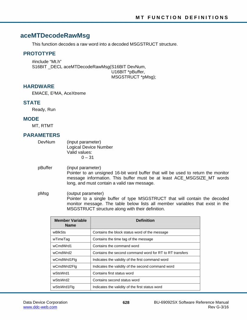
M T F U N C T I O N D E F I N I T I O N S
Data Device Corporation BU-69092SX Software Reference Manual www.ddc-web.com Rev G-3/16
628
aceMTDecodeRawMsg This function decodes a raw word into a decoded MSGSTRUCT structure.
PROTOTYPE #include “Mt.h” S16BIT _DECL aceMTDecodeRawMsg(S16BIT DevNum, U16BIT *pBuffer, MSGSTRUCT *pMsg);
HARDWARE EMACE, E²MA, AceXtreme
STATE Ready, Run
MODE MT, RTMT
PARAMETERS DevNum (input parameter) Logical Device Number Valid values: 0 – 31 pBuffer (input parameter)
Pointer to an unsigned 16-bit word buffer that will be used to return the monitor message information. This buffer must be at least ACE_MSGSIZE_MT words long, and must contain a valid raw message.
pMsg (output parameter)
Pointer to a single buffer of type MSGSTRUCT that will contain the decoded monitor message. The table below lists all member variables that exist in the MSGSTRUCT structure along with their definition.
Member Variable
Name Definition
wBlkSts Contains the block status word of the message
wTimeTag Contains the time tag of the message
wCmdWrd1 Contains the command word
wCmdWrd2 Contains the second command word for RT to RT transfers
wCmdWrd1Flg Indicates the validity of the first command word
wCmdWrd2Flg Indicates the validity of the second command word
wStsWrd1 Contains first status word
wStsWrd2 Contains second status word
wStsWrd1Flg Indicates the validity of the first status word

M T F U N C T I O N D E F I N I T I O N S
Data Device Corporation BU-69092SX Software Reference Manual www.ddc-web.com Rev G-3/16
629
aceMTDecodeRawMsg (continued) Member Variable
Name Definition
wStsWrd2Flg Indicates the validity of the second status word
wWordCount Contains the number of valid data words
aDataWrds[32] An array that will contain the data words
wBCCtrlWrd Contains the BC Control Word for BC mode messages only
wBCGapTime Contains the message gap time only for BC
wBCLoopBack1 Contains the first looped back word for BC mode messages only
wTimeTag2 Not used in MT Mode. MT Time Tag is only 16 bits
wBCLoopBack1Flg Indicates validity of first loop back word for BC mode message only
wTimeTag3 Not used in MT Mode. MT Time Tag is only 16 bits
DESCRIPTION This function takes an ACE_MSGSIZE_MT word buffer and decodes the raw message it contains into a decoded MSGSTRUCT structure.
RETURN VALUE ACE_ERR_SUCCESS The function completed successfully ACE_ERR_INVALID_DEVNUM An invalid device number was input by the user ACE_ERR_INVALID_STATE The device is not in a Run or Ready state ACE_ERR_INVALID_MODE The device is not in MT or RTMT mode ACE_ERR_MSGSTRUCT The pMsg parameter is Null ACE_ERR_INVALID_BUF The pBuffer input parameter is Null
EXAMPLE S16BIT DevNum = 0; S16BIT nResult = 0; U16BIT pBuffer[ACE_MSGSIZE_MT]; MSGSTRUCT pMsg; /* Initialize device for monitor mode, run the monitor. Read a message into pBuffer (see aceMTGetStkMsgsRaw or aceMTGetHBufMsgsRaw) */ nResult = aceMTDecodeRawMsg(DevNum,pBuffer, &pMsg); if(nResult) { printf(“Error in aceMTDecodeRawMsg() function \n”); PrintOutError(nResult); return; }

M T F U N C T I O N D E F I N I T I O N S
Data Device Corporation BU-69092SX Software Reference Manual www.ddc-web.com Rev G-3/16
630
aceMTDecodeRawMsg (continued) SEE ALSO
None

M T F U N C T I O N D E F I N I T I O N S
Data Device Corporation BU-69092SX Software Reference Manual www.ddc-web.com Rev G-3/16
631
aceMTDisableRTFilter This function allows the user to NOT monitor selective data.
PROTOTYPE #include “Mt.h” S16BIT _DECL aceMTDisableRTFilter(S16BIT DevNum, U16BIT wRT, U16BIT wTR, U32BIT dwSAMask);
HARDWARE EMACE, E²MA, AceXtreme
STATE Ready, Run
MODE MT, RTMT, MT-I, RTMT-I
PARAMETERS DevNum (input parameter) Logical Device Number Valid values: 0 – 31 wRT (input parameter)
Specify the RT address of the message to stop from being monitored based on the other parameters.
Valid values: 0 – 31 Selects one RT subaddress value ACE_MT_FILTER_ALL Specifies all RT subaddresses wTR (input parameter)
Specify the Transmit/Receive bit of the message to stop from being filtered. Valid values: ACE_MT_FILTER_TX Only Transmit ACE_MT_FILTER_RX Only Receive ACE_MT_FILTER_ALL Transmit and Receive
M T F U N C T I O N D E F I N I T I O N S
Data Device Corporation BU-69092SX Software Reference Manual www.ddc-web.com Rev G-3/16
632
aceMTDisableRTFilter (continued) dwSAMask (input parameter)
Specify the subaddresses of the message to stop from being filtered. OR’ed combination of the following valid values.
Valid values: ACE_MT_FILTER_SA_ALL All subaddresses to stop from being filtered ACE_MT_FILTER_SAXX Specific subaddress to stop from being filtered, where XX ranges from 0 -
31
DESCRIPTION The AceXtreme C SDK provides a flexible interface that allows selective monitoring of 1553 messages based on the RT address, T/R bit, and subaddress with very little host processor intervention. The Message Monitor mode of the 1553 hardware recreates all command/response messages on the 1553 bus on channels A and B, and stores them into the shared RAM based on a user programmable filter (RT address, T/R bit, and subaddress). This monitor can be used as a monitor alone or in a combined RT/Monitor mode. This function writes to the MT Selective Monitor Lookup table. It sets the appropriate bits associated with a RT address, T/R bit, and subaddress. Any commands with those subaddresses that have their bits cleared WILL NOT be monitored.
RETURN VALUE ACE_ERR_SUCCESS The function completed successfully ACE_ERR_INVALID_DEVNUM An invalid device number was input by the user ACE_ERR_INVALID_STATE The device is not in a Ready or Run state ACE_ERR_INVALID_MODE The device is not in MT or RTMT mode ACE_ERR_MT_FILTER_RT The wRT input parameter contains a value greater than 31
or it is not equal to ACE_MT_FILTER_ALL ACE_ERR_MT_FILTER_TR The wTR input parameter does not contain one of the
following valid values: ACE_MT_FILTER_TX ACE_MT_FILTER_RX ACE_MT_FILTER_ALL
M T F U N C T I O N D E F I N I T I O N S
Data Device Corporation BU-69092SX Software Reference Manual www.ddc-web.com Rev G-3/16
633
aceMTDisableRTFilter (continued) EXAMPLE
S16BIT DevNum = 0; S16BIT nResult = 0; U16BIT wRT = 10, wTR = ACE_MT_FILTER_TX; U32BIT dwSAMask = ACE_MT_FILTER_SA5 + ACE_MT_FILTER_SA30; /* Set Monitor operation to NOT monitor TRANSMIT messages to RT 10 for subaddresses 5 and 30. */ nResult = aceMTDisableRTFilter(DevNum, wRT, wTR, dwSAMask); if(nResult) { printf(“Error in aceMTDisableRTFilter() function \n”); PrintOutError(nResult); return; }
SEE ALSO aceMTEnableRTFilter() aceMTGetRTFilter()

M T F U N C T I O N D E F I N I T I O N S
Data Device Corporation BU-69092SX Software Reference Manual www.ddc-web.com Rev G-3/16
634
aceMTEnableRTFilter This function allows the user to only monitor selective data.
PROTOTYPE #include “Mt.h” S16BIT _DECL aceMTEnableRTFilter(S16BIT DevNum, U16BIT wRT, U16BIT wTR, U32BIT dwSAMask)
HARDWARE EMACE, E²MA, AceXtreme
STATE Ready, Run
MODE MT, RTMT, MT-I, RTMT-I
PARAMETERS DevNum (input parameter) Logical Device Number Valid values: 0 – 31 wRT (input parameter)
Specify the RT address of the message to be monitored based on the other parameters.
Valid values: 0 – 31 Selects one RT subaddress value ACE_MT_FILTER_ALL Specifies all RT subaddresses wTR (input parameter) Specify the Transmit/Receive bit of the message to be filtered. Valid values: ACE_MT_FILTER_TX Only Transmit ACE_MT_FILTER_RX Only Receive ACE_MT_FILTER_ALL Transmit and Receive

M T F U N C T I O N D E F I N I T I O N S
Data Device Corporation BU-69092SX Software Reference Manual www.ddc-web.com Rev G-3/16
635
aceMTEnableRTFilter (continued) dwSAMask (input parameter)
Specify the subaddresses of the message to be filtered. OR’ed combination of the following valid values.
Valid values: ACE_MT_FILTER_SA_ALL All subaddresses to be filtered ACE_MT_FILTER_SAXX Specific subaddress to be filtered, where XX ranges from 0 -31
DESCRIPTION The AceXtreme C SDK provides a flexible interface that allows selective monitoring of 1553 messages based on the RT address, T/R bit, and subaddress with very little host processor intervention. The Message Monitor mode of the 1553 hardware recreates all command/response messages on the 1553 bus on channels A and B, and stores them into the shared RAM based on a user programmable filter (RT address, T/R bit, and subaddress). This monitor can be used as a monitor alone or in a combined RT/Monitor mode. This function writes to the MT Selective Monitor Lookup table. It sets the appropriate bits associated with a RT address, T/R bit, and subaddress. Any commands with those subaddresses that have their bits set WILL be monitored.
RETURN VALUE ACE_ERR_SUCCESS The function completed successfully ACE_ERR_INVALID_DEVNUM An invalid device number was input by the user ACE_ERR_INVALID_STATE The device is not in a Ready or Run state ACE_ERR_INVALID_MODE The device is not in MT or RTMT mode ACE_ERR_MT_FILTER_RT The wRT input parameter contains a value greater than 31
or it is not equal to ACE_MT_FILTER_ALL ACE_ERR_MT_FILTER_TR The wTR input parameter does not contain one of the
following valid values: ACE_MT_FILTER_TX ACE_MT_FILTER_RX ACE_MT_FILTER_ALL
M T F U N C T I O N D E F I N I T I O N S
Data Device Corporation BU-69092SX Software Reference Manual www.ddc-web.com Rev G-3/16
636
aceMTEnableRTFilter (continued) EXAMPLE
S16BIT DevNum = 0; S16BIT nResult = 0; U16BIT wRT = 10, wTR = ACE_MT_FILTER_TX; U32BIT dwSAMask = ACE_MT_FILTER_SA5 + ACE_MT_FILTER_SA30; /* Set Monitor operation to only monitor TRANSMIT messages to RT 10 for subaddresses 5 and 30. All other messages will be ignored. */ nResult = aceMTEnableRTFilter(DevNum, wRT, wTR, dwSAMask); if(nResult) { printf(“Error in aceMTEnableRTFilter() function \n”); PrintOutError(nResult); return; }
SEE ALSO aceMTDisableRTFilter() aceMTGetRTFilter()

M T F U N C T I O N D E F I N I T I O N S
Data Device Corporation BU-69092SX Software Reference Manual www.ddc-web.com Rev G-3/16
637
aceMTGetHBufMetric This function returns performance information about the Host Buffer.
PROTOTYPE #include “bc.h” S16BIT _DECL aceMTGetHBufMetric(S16BIT DevNum, HBUFMETRIC *pMetric, U16BIT bReset);
HARDWARE EMACE, E²MA, AceXtreme
STATE Ready, Run
MODE MT, RTMT
PARAMETERS DevNum (input parameter) Logical Device Number Valid values: 0 – 31 pMetric (output parameter) Pointer to an HBUFMETRIC structure to be filled in with metrics
Member Variable Name Definition dwCount The number of messages in the host buffer
dwLost The total number of messages lost since the host buffer was installed
dwPctFull The current percentage of host buffer used
dwHighPct The highest percentage of the host buffer used since the host buffer was installed or metrics were reset
bReset (input parameter)
This will specify if the highest percentage value should be reset after this function returns
Valid values: FALSE (0) Do not reset the highest percentage value TRUE (1) Reset the highest percentage value

M T F U N C T I O N D E F I N I T I O N S
Data Device Corporation BU-69092SX Software Reference Manual www.ddc-web.com Rev G-3/16
638
aceMTGetHBufMetric (continued) DESCRIPTION
This function returns performance information about the Host Buffer. Built-in test metrics can report the number of messages in the host buffer, the total number of messages lost since the host buffer was installed, the current percentage of the host buffer that is used, and the highest percentage of the host buffer used since it was installed.
RETURN VALUE ACE_ERR_SUCCESS The function completed successfully ACE_ERR_INVALID_DEVNUM An invalid device number was input by the user ACE_ERR_INVALID_STATE The device is not in a Ready or Run state ACE_ERR_INVALID_MODE The device is not in MT or RTMT mode ACE_ERR_PARAMETER The pMetric pointer input by the user is NULL ACE_ERR_RTMT_COMBO_HBUF An MT host buffer is not used but an RTMT host
buffer is being used ACE_ERR_METRICS_NOT_ENA Metrics are not enabled and should be set by
calling the aceSetMetrics() function
EXAMPLE S16BIT DevNum = 0; HBUFMETRIC *pMetric; U16BIT bReset = 1; S16BIT nResult = 0; nResult = aceMTGetHBufMetric(DevNum, pMetric, bReset) if(nResult) { printf(“Error in aceMTGetHBufMetric() function \n”); PrintOutError(nResult); return; }
SEE ALSO aceSetMetrics() aceMTGetStkMetric() aceRTGetHBufMetric() aceRTGetStkMetric()

M T F U N C T I O N D E F I N I T I O N S
Data Device Corporation BU-69092SX Software Reference Manual www.ddc-web.com Rev G-3/16
639
aceMTGetHBufMsgCount This function returns the number of messages in the host buffer.
PROTOTYPE #include “Mt.h” S16BIT _DECL aceMTGetHBufMsgCount(S16BIT DevNum);
HARDWARE EMACE, E²MA, AceXtreme
STATE Ready, Run
MODE MT, RTMT
PARAMETERS DevNum Logical Device Number Valid values: 0 – 31
DESCRIPTION This function returns the number of messages that are currently in the host buffer.
RETURN VALUE S16BIT nResult The number of messages in the host buffer ACE_ERR_INVALID_DEVNUM An invalid device number was input by the user ACE_ERR_INVALID_STATE The device is not in a Ready or Run state ACE_ERR_INVALID_MODE The device is not in MT or RTMT mode
EXAMPLE S16BIT DevNum = 0; S16BIT nResult = 0; nResult = aceMTGetHBufMsgCount(DevNum); if(nResult < 0) { PrintOutError(nResult); return; } printf(“Number of messages in Host Buffer = %d\n”, nResult);
SEE ALSO None

M T F U N C T I O N D E F I N I T I O N S
Data Device Corporation BU-69092SX Software Reference Manual www.ddc-web.com Rev G-3/16
640
aceMTGetHBufMsgDecoded This function reads a single decoded message from the host buffer if it is present.
PROTOTYPE #include “Mt.h” S16BIT _DECL aceMTGetHBufMsgDecoded( S16BIT DevNum, MSGSTRUCT *pMsg, U32BIT *pdwMsgCount, U32BIT *pdwMsgLostStk, U32BIT *pdwMsgLostHBuf, U16BIT wMsgLoc);
HARDWARE EMACE, E²MA, AceXtreme
STATE Ready, Run
MODE MT, RTMT
PARAMETERS DevNum (input parameter) Logical Device Number Valid values: 0 – 31 pMsg (output parameter)
Pointer to a parameter of type MSGSTRUCT that will be used to return the decoded message from the host buffer. The table below lists all member variables that exist in the MSGSTRUCT structure along with their definition.
Member Variable
Name Definition
wBlkSts Contains the block status word of the message
wTimeTag Contains the time tag of the message
wCmdWrd1 Contains the command word
wCmdWrd2 Contains the second command word for RT to RT transfers
wCmdWrd1Flg Indicates the validity of the first command word
wCmdWrd2Flg Indicates the validity of the second command word
wStsWrd1 Contains first status word
wStsWrd2 Contains second status word
wStsWrd1Flg Indicates the validity of the first status word

M T F U N C T I O N D E F I N I T I O N S
Data Device Corporation BU-69092SX Software Reference Manual www.ddc-web.com Rev G-3/16
641
aceMTGetHBufMsgDecoded (continued) Member Variable
Name Definition
wStsWrd2Flg Indicates the validity of the second status word
wWordCount Contains the number of valid data words
aDataWrds[32] An array that will contain the data words
wBCCtrlWrd Contains the BC Control Word for BC mode messages only
wBCGapTime Contains the message gap time only for BC
wBCLoopBack1 Contains the first looped back word for BC mode messages only
wTimeTag2 Not used in MT Mode. MT Time Tag is only 16 bits
wBCLoopBack1Flg Indicates validity of first loop back word for BC mode message only
wTimeTag3 Not used in MT Mode. MT Time Tag is only 16 bits
pdwMsgCount (output parameter)
Pointer to an unsigned 32-bit parameter to be filled with message count. Valid return values: 0 - No message returned in pMsg 1 - One message returned in pMsg pdwMsgLostStk (output parameter)
Pointer to an unsigned 32-bit word that will contain the approximate number of messages lost due to overwrite prior to transferring the messages from the hardware to the host buffer.
pdwMsgLostHBuf (output parameter)
Pointer to an unsigned 32-bit word that will contain the approximate number of messages lost while transferring the messages from the host buffer to the user buffer.
wMsgLoc (input parameter)
Specify what message should be read off the Host Buffer. The choice is to read the next unread message or the last received message. Additionally, this parameter indicates whether to purge or not purge the message read.
Valid values: ACE_MT_MSGLOC_NEXT_PURGE Reads next message and takes it off of the host buffer ACE_MT_MSGLOC_NEXT_NPURGE Reads next message and leaves it on the host buffer ACE_MT_MSGLOC_LATEST_PURGE Reads current message and takes it off of the host buffer ACE_MT_MSGLOC_LATEST_NPURGE Reads current message and leaves it on the host buffer

M T F U N C T I O N D E F I N I T I O N S
Data Device Corporation BU-69092SX Software Reference Manual www.ddc-web.com Rev G-3/16
642
aceMTGetHBufMsgDecoded (continued) DESCRIPTION
This function reads a single decoded message from the host buffer if it is present. The function will use the aceMTDecodeRawMsg() function to decode the raw message into the MSGSTRUCT structure.
RETURN VALUE ACE_ERR_SUCCESS The function completed successfully ACE_ERR_INVALID_DEVNUM An invalid device number was input by the user ACE_ERR_INVALID_STATE The device is not in a Ready or Run state ACE_ERR_INVALID_MODE The device is not in MT or RTMT mode ACE_ERR_PARAMETER The pdwMsgLostStk input parameter is Null and/or the
pdwMsgLostHBuf input parameter is Null ACE_ERR_MT_MSGLOC The wMsgLoc input parameter is not one of the following
valid values: ACE_MT_MSGLOC_NEXT_PURGE
ACE_MT_MSGLOC_NEXT_NPURGE ACE_MT_MSGLOC_LATEST_PURGE ACE_MT_MSGLOC_LATEST_NPURG
EXAMPLE S16BIT DevNum = 0; S16BIT nResult = 0; U32BIT pdwMsgCount, pdwMsgLostStk, pdwMsgLostHBuf; MSGSTRUCT *pMsg; U16BIT wMsgLoc = 2; nResult = aceMTGetHBufMsgDecoded(DevNum, &pMsg, &pdwMsgCount, &pdwMsgLostStk, &pdwMsgLostHBuf, wMsgLoc); if(nResult) { printf(“Error in aceMTGetHBufMsgDecoded() function \n”); PrintOutError(nResult); return; } if(!pdwMsgCount) printf(“No message returned from Host Buffer\n”);
SEE ALSO aceMTStkToHBuf() aceMTGetHBufMsgsRaw()

M T F U N C T I O N D E F I N I T I O N S
Data Device Corporation BU-69092SX Software Reference Manual www.ddc-web.com Rev G-3/16
643
aceMTGetHBufMsgsRaw This function reads as many messages as possible off of the host buffer into a user buffer.
PROTOTYPE #include “Mt.h” S16BIT _DECL aceMTGetHBufMsgsRaw(S16BIT DevNum, U16BIT *pBuffer, U16BIT wBufferSize, U32BIT *pdwMsgCount, U32BIT *pdwMsgLostStk, U32BIT *pdwMsgLostHBuf);
HARDWARE EMACE, E²MA, AceXtreme
STATE Ready, Run
MODE MT, RTMT
PARAMETERS DevNum (input parameter) Logical Device Number Valid values: 0 – 31 pBuffer (output parameter)
Pointer to an unsigned 16-bit word buffer that will receive the raw messages from the host buffer.
wBufferSize (input parameter)
Specify the size of the pBuffer buffer that will receive the raw messages from the host buffer.
Valid values: There is no restriction on the size of this buffer, but for efficiency of
resource use, the size of this buffer should be calculated as Number of messages * ACE_MSGSIZE_MT.
pdwMsgCount (output parameter)
If no errors occurred, this is the return value of the number of messages transferred to the pBuffer buffer.

M T F U N C T I O N D E F I N I T I O N S
Data Device Corporation BU-69092SX Software Reference Manual www.ddc-web.com Rev G-3/16
644
aceMTGetHBufMsgsRaw (continued) pdwMsgLostStk (output parameter) Estimates the number of messages lost due to overwrite prior to transferring the messages from the hardware to the host buffer. pdwMsgLostHBuf (output parameter) Estimates the number of messages lost, due to overwrite when transferring the messages from the host buffer to the user buffer.
DESCRIPTION This function reads as many messages as possible off of the host buffer into a user buffer without any decoding. The limiting factor when copying messages to the local buffer is the local buffer size and the number of messages available on the host buffer.
Note: Each message is a fixed length of ACE_MSGSIZE_MT words. This macro must be used in size calculations as the size of the structure is subject to change.
RETURN VALUE ACE_ERR_SUCCESS The function completed successfully ACE_ERR_INVALID_DEVNUM An invalid device number was input by the user ACE_ERR_INVALID_STATE The device is not in a Ready or Run state ACE_ERR_INVALID_MODE The device is not in MT or RTMT mode ACE_ERR_PARAMETER The pdwMsgLostStk input parameter is Null and/or the
pdwMsgLostHBuf input parameter is Null
EXAMPLE S16BIT DevNum = 0; S16BIT nResult = 0; U16BIT pBuffer[ACE_MSGSIZE_MT * 256]; U16BIT wBufferSize = ACE_MSGSIZE_MT * 256; U32BIT pdwMsgCount, pdwMsgLostStk, pdwMsgLostHBuf; nResult = aceMTGetHBufMsgsRaw(DevNum, pBuffer, wBufferSize, &pdwMsgCount, &pdwMsgLostStk, &pdwMsgLostHBuf); if(nResult) { printf(“Error in aceMTGetHBufMsgsRaw() function \n”); PrintOutError(nResult); return; }
SEE ALSO aceMTStkToHBuf() aceMTGetHBufMsgDecoded()

M T F U N C T I O N D E F I N I T I O N S
Data Device Corporation BU-69092SX Software Reference Manual www.ddc-web.com Rev G-3/16
645
aceMTGetInfo This function will return the current configuration of the Monitor.
PROTOTYPE #include “Mt.h” S16BIT _DECL aceMTGetInfo(S16BIT DevNum, MTINFO *pInfo);
HARDWARE EMACE, E²MA, AceXtreme
STATE Ready, Run
MODE MT, RTMT
PARAMETERS DevNum (input parameter) Logical Device Number Valid values: 0 – 31 pInfo (output parameter)
Pointer to a structure of type MTINFO that will be used to return the monitor mode information.
DESCRIPTION This function takes in the address of an MTINFO structure and fills it in with the current configuration of the monitor. The returned structure will contain the following information: Command stack size Data stack size WStkMode (Double or Single) 1553 A Mode code use Host buffer size
RETURN VALUE ACE_ERR_SUCCESS The function completed successfully ACE_ERR_INVALID_DEVNUM An invalid device number was input by the user ACE_ERR_INVALID_STATE The device is not in a Ready or Run state ACE_ERR_INVALID_MODE The device is not in MT or RTMT mode ACE_ERR_MT_HBUF The host buffer does not exist

M T F U N C T I O N D E F I N I T I O N S
Data Device Corporation BU-69092SX Software Reference Manual www.ddc-web.com Rev G-3/16
646
aceMTGetInfo (continued) EXAMPLE
S16BIT DevNum = 0; S16BIT nResult = 0; MTINFO *pInfo; /* After setup of the monitor, the following statement can be used to identify some of the monitor information. */ nResult = aceMTGetInfo(DevNum, pInfo); if(nResult) { printf(“Error in aceMTGetInfo() function \n”); PrintOutError(nResult); return; } printf(“wStkMode = %s\nCommand stack size = %d\nData stack size = %d\n1553 A Mode code usage %s\nHost buffer size = %d\n”, pInfo->wStkMode== ACE_MT_DOUBLESTK?”Double”:”Single”, pInfo->wCmdStkSize, pInfo->wDataStkSize , pInfo->b1553aMCodes == TRUE?”Yes”:”No”, pInfo->dwHBufSize);
SEE ALSO None

M T F U N C T I O N D E F I N I T I O N S
Data Device Corporation BU-69092SX Software Reference Manual www.ddc-web.com Rev G-3/16
647
aceMTGetRTFilter This function will read the selective Monitor Lookup table.
PROTOTYPE #include “Mt.h” S16BIT _DECL aceMTDisableRTFilter(S16BIT DevNum, U16BIT wRT, U16BIT wTR, U32BIT * pSAMask);
HARDWARE EMACE, E²MA, AceXtreme
STATE Ready, Run
MODE MT, RTMT, MT-I, RTMT-I
PARAMETERS DevNum (input parameter) Logical Device Number Valid values: 0 – 31 wRT (input parameter) Specify the RT address of the message to get the filtering status. Valid values: 0 – 31 Selects one RT subaddress value wTR (input parameter) Specify the Transmit/Receive bit of the message to get the filtering status. Valid values: ACE_MT_FILTER_TX Only Transmit ACE_MT_FILTER_RX Only Receive

M T F U N C T I O N D E F I N I T I O N S
Data Device Corporation BU-69092SX Software Reference Manual www.ddc-web.com Rev G-3/16
648
aceMTGetRTFilter (continued) pSAMask (output parameter)
Pointer to an unsigned 32-bit value that will be used to return a 32-bit packed value that represents the subaddresses that will be monitored for the given Remote Terminal and T/R bit combination. The result can be compared to the following values.
Valid values: ACE_MT_FILTER_SA_ALL All subaddresses ACE_MT_FILTER_SAXX Specific subaddress where XX ranges from 0 -31
DESCRIPTION The AceXtreme C SDK provides a flexible interface that allows selective monitoring of 1553 messages based on RT Address, T/R, and Subaddress with very little host processor intervention. The Message Monitor mode of the 1553 hardware recreates all command/response messages on the 1553 bus on channels A and B, and stores them into the shared RAM based on a user programmable filter (RT address, T/R bit, and subaddress). This monitor can be used as a monitor alone or in a combined RT/Monitor mode. This function reads the Filter status for the selected Remote Terminal based upon the RT address and the Transmit/Receive bit. The status returned will be a bit packed U32BIT value that represents the RT’s subaddresses that will be monitored. The least significant bit represents SA0 while the most significant bit represents SA31. If the corresponding bit of a subaddress is set, then all messages to the RT that match the T/R will be monitored, otherwise they will not be.
RETURN VALUE ACE_ERR_SUCCESS The function completed successfully ACE_ERR_INVALID_DEVNUM An invalid device number was input by the user ACE_ERR_INVALID_STATE The device is not in a Ready or Run state ACE_ERR_INVALID_MODE The device is not in MT or RTMT mode ACE_ERR_MT_FILTER_RT The wRT input parameter contains a value greater than 31 ACE_ERR_MT_FILTER_TR The wTR input parameter contains a value that is not one of
the following valid values: ACE_MT_FILTER_TX ACE_MT_FILTER_RX ACE_ERR_MT_FILTER_SA The pSAMask parameter is Null

M T F U N C T I O N D E F I N I T I O N S
Data Device Corporation BU-69092SX Software Reference Manual www.ddc-web.com Rev G-3/16
649
aceMTGetRTFilter (continued) EXAMPLE
S16BIT DevNum = 0; S16BIT nResult = 0; U16BIT wRT = 10, wTR = ACE_MT_FILTER_TX; U32BIT pwSAMask; /* Read the monitor filter table for Remote Terminal 10 transmit messages. The return value “pwSAMask” may be decoded with the following macros: ACE_MT_FILTER_SA_ALL = All subaddresses ACE_MT_FILTER_SAXX = Specific subaddress */ nResult = aceMTGetRTFilter(DevNum, wRT, wTR, &pwSAMask); if(nResult) { printf(“Error in aceMTGetRTFilter() function \n”); PrintOutError(nResult); return; }
SEE ALSO aceMTDisableRTFilter() aceMTEnableRTFilter()

M T F U N C T I O N D E F I N I T I O N S
Data Device Corporation BU-69092SX Software Reference Manual www.ddc-web.com Rev G-3/16
650
aceMTGetStkMetric This function returns performance information about the MT Command Stack.
PROTOTYPE #include “mt.h” S16BIT _DECL aceMTGetHBufMetric(S16BIT DevNum, STKMETRIC *pMetric, U16BIT wStk, U16BIT bReset);
HARDWARE EMACE, E²MA, AceXtreme
STATE Ready, Run
MODE MT, RTMT
PARAMETERS DevNum (input parameter) Logical Device Number Valid values: 0 – 31 pMetric (output parameter)
Pointer to a STKMETRIC structure to be filled in with metrics. The STKMETRIC structure contains the following members: dwLost, dwPctFull, and dwHighPct. The dwLost member parameter contains the total number of messages lost on the hardware stack. The dwPctFull member parameter contains the percentage of the stack used at one snapshot in time. The dwHighPct member parameter contains the highest percentage of the stack used over an extended period of time.
wStk (input parameter) Specifies the stack to get metrics for the following values. Valid values: ACE_MT_STKA Will get metrics for stack A ACE_MT_STKB Will get metrics for stack B ACE_MT_STK_CMB Will get the average metrics for stack A and B

M T F U N C T I O N D E F I N I T I O N S
Data Device Corporation BU-69092SX Software Reference Manual www.ddc-web.com Rev G-3/16
651
aceMTGetStkMetric (continued) bReset (input parameter)
This will specify if the highest percentage value should be reset after this function returns
Valid values: FALSE (0) Do not reset the highest percentage value TRUE (1) Reset the highest percentage value
DESCRIPTION This function returns performance information about the MT Command Stack (also referred to as the MT Descriptor Stack). Built-in test metrics can report the number of messages in the host buffer, the total number of messages lost since the host buffer was installed, the current percentage of the host buffer that is used, and the highest percentage of the host buffer used since it was installed. In order to use this function, a call to aceMTGetStkMsgDecoded() must be made to read the stack with the NPURGE option.
RETURN VALUE ACE_ERR_SUCCESS The function completed successfully ACE_ERR_INVALID_DEVNUM An invalid device number was input by the user ACE_ERR_INVALID_STATE The device is not in a Ready or Run state ACE_ERR_INVALID_MODE The device is not in MT or RTMT mode ACE_ERR_PARAMETER The pMetric pointer input by the user is NULL and/or the
wStk input parameter does not contain one of the following valid values: ACE_MT_STKA, ACE_MT_STKB, ACE_MT_STK_CMB
ACE_ERR_METRICS_NOT_ENA Metrics are not enabled and should be set by calling the aceSetMetrics() function
EXAMPLE S16BIT DevNum = 0; STKMETRIC *pMetric; U16BIT wStk = ACE_MT_STKA U16BIT bReset = 1; S16BIT nResult = 0; nResult = aceMTGetStkMetric(DevNum, pMetric, wStk, bReset) if(nResult) { printf(“Error in aceMTGetStkMetric() function \n”); PrintOutError(nResult); return; }

M T F U N C T I O N D E F I N I T I O N S
Data Device Corporation BU-69092SX Software Reference Manual www.ddc-web.com Rev G-3/16
652
aceMTGetStkMetric (continued) SEE ALSO
aceSetMetrics() aceMTGetHBufMetric() aceRTGetHBufMetric() aceRTGetStkMetric()

M T F U N C T I O N D E F I N I T I O N S
Data Device Corporation BU-69092SX Software Reference Manual www.ddc-web.com Rev G-3/16
653
aceMTGetStkMsgDecoded This function reads a message on the Monitor stack and decodes it.
PROTOTYPE #include “Mt.h” S16BIT _DECL aceMTGetStkMsgDecoded(S16BIT DevNum, MSGSTRUCT *pMsg, U16BIT wMsgLoc, U16BIT wStkLoc);
HARDWARE EMACE, E²MA, AceXtreme
STATE Ready, Run
MODE MT, RTMT
PARAMETERS DevNum (input parameter) Logical Device Number Valid values: 0 – 31 pMsg (output parameter)
Pointer to a buffer of type MSGSTRUCT that will be used to return the decoded monitor message from the stack. The table below lists all member variables that exist in the MSGSTRUCT structure along with their definition.
Member Variable
Name Definition
wBlkSts Contains the block status word of the message
wTimeTag Contains the time tag of the message
wCmdWrd1 Contains the command word
wCmdWrd2 Contains the second command word for RT to RT transfers
wCmdWrd1Flg Indicates the validity of the first command word
wCmdWrd2Flg Indicates the validity of the second command word
wStsWrd1 Contains first status word
wStsWrd2 Contains second status word
wStsWrd1Flg Indicates the validity of the first status word
wStsWrd2Flg Indicates the validity of the second status word

M T F U N C T I O N D E F I N I T I O N S
Data Device Corporation BU-69092SX Software Reference Manual www.ddc-web.com Rev G-3/16
654
aceMTGetStkMsgDecoded (continued) Member Variable
Name Definition
wWordCount Contains the number of valid data words
aDataWrds[32] An array that will contain the data words
wBCCtrlWrd Contains the BC Control Word for BC mode messages only
wBCGapTime Contains the message gap time only for BC
wBCLoopBack1 Contains the first looped back word for BC mode messages only
wTimeTag2 Not used in MT Mode. MT Time Tag is only 16 bits
wBCLoopBack1Flg Indicates validity of first loop back word for BC mode message only
wTimeTag3 Not used in MT Mode. MT Time Tag is only 16 bits
wMsgLoc (input parameter)
Specify where the message is located on the selected stack. This parameter also indicates whether or not the selected message should be purged from the stack.
Valid values: ACE_MT_MSGLOC_NEXT_PURGE Retrieves the next message and takes it off of the stack ACE_MT_MSGLOC_NEXT_NPURGE Retrieves the next message and leaves it on the stack ACE_MT_MSGLOC_LATEST_PURGE Retrieves the current message and takes it off of the stack ACE_MT_MSGLOC_LATEST_NPURGE Retrieves the current message and leaves it on the stack wStkLoc (input parameter) Defines which monitor stack that should be read. The monitor has two stacks that may be accessed as Stack A or Stack B. These two stacks may also be identified as the Active stack (the hardware is currently writing the active stack) or the Inactive stack (the hardware does not have access to the inactive stack until the stacks are swapped). Valid values: ACE_MT_STKLOC_ACTIVE Reads the active stack

M T F U N C T I O N D E F I N I T I O N S
Data Device Corporation BU-69092SX Software Reference Manual www.ddc-web.com Rev G-3/16
655
aceMTGetStkMsgDecoded (continued) ACE_MT_STKLOC_INACTIVE Reads the inactive stack ACE_MT_STKLOC_STKA Reads stack A ACE_MT_STKLOC_STKB Reads stack B
DESCRIPTION This function reads either the next unread message or the latest message the monitor placed on the stack. The function decodes the message by placing all of the message information into a MSGSTRUCT. This function decodes the raw message into a MSGSTRUCT structure by calling the aceMTDecodeRawMsg() function.
RETURN VALUE S16BIT nResult Number of messages returned: 1 = message read 0 = message not read ACE_ERR_INVALID_DEVNUM An invalid device number was input by the user ACE_ERR_INVALID_STATE The device is not in a Run or Ready state ACE_ERR_INVALID_MODE The device is not in MT or RTMT mode ACE_ERR_MSGSTRUCT The pMsg parameter is Null ACE_ERR_MT_STKLOC The wStkLoc input parameter contains a value that
is not one of the following valid types: ACE_MT_STKLOC_ACTIVE ACE_MT_STKLOC_INACTIVE ACE_MT_STKLOC_STKA ACE_MT_STKLOC_STKB ACE_ERR_MT_MSGLOC The wMsgLoc input parameter contains a value
that is not one of the following valid types: ACE_MT_MSGLOC_NEXT_PURGE
Reads next message and takes it off of the stack ACE_MT_MSGLOC_NEXT_NPURGE
Reads next message and leaves it on the stack ACE_MT_MSGLOC_LATEST_PURGE
Reads current message and takes it off of the stack ACE_MT_MSGLOC_LATEST_NPURGE
Reads current message and leaves it on the stack

M T F U N C T I O N D E F I N I T I O N S
Data Device Corporation BU-69092SX Software Reference Manual www.ddc-web.com Rev G-3/16
656
aceMTGetStkMsgDecoded (continued) EXAMPLE
S16BIT DevNum = 0; S16BIT nResult = 0; MSGSTRUCT pMsg; U16BIT wStkLoc = ACE_MT_STKLOC_INACTIVE; U16BIT wMsgLoc = ACE_MT_MSGLOC_LATEST_PURGE; /* Initialize Monitor, and start running. Read the latest message from the inactive stack and purge the message when it is read. */ nResult = aceMTGetStkMsgDecoded(DevNum, &pMsg, wMsgLoc, wStkLoc); if(nResult < 0) { printf(“Error in aceMTGetStkMsgDecoded() function \n”); PrintOutError(nResult); return; } printf(“message read = %s\n”, nResult?”TRUE”:”FALSE”);
SEE ALSO aceMTGetStkMsgsRaw()

M T F U N C T I O N D E F I N I T I O N S
Data Device Corporation BU-69092SX Software Reference Manual www.ddc-web.com Rev G-3/16
657
aceMTGetStkMsgsRaw This function reads as many messages as possible off of a given stack.
PROTOTYPE #include “Mt.h” S16BIT _DECL aceMTGetStkMsgsRaw(S16BIT DevNum, U16BIT *pBuffer, U16BIT wBufferSize, U16BIT wStkLoc);
HARDWARE EMACE, E²MA, AceXtreme
STATE Ready, Run
MODE MT, RTMT
PARAMETERS DevNum (input parameter) Logical Device Number Valid values: 0 – 31 pBuffer (output parameter)
Pointer to an unsigned 16-bit word buffer that will be used to return the monitor message information.
wBufferSize (input parameter) Size of buffer in words. Valid values: There is no restriction for the size of the buffer, but the most
efficient use of resources is to create a buffer that is ACE_MSGSIZE_MT * the number of messages.
wStkLoc (input parameter)
Defines which monitor stack that should be read. The monitor has two stacks that may be accessed as Stack A or Stack B. These two stacks may also be identified as the Active stack (the hardware is currently writing the active stack) or the Inactive stack (the hardware does not have access to the inactive stack until the stacks are swapped).
Valid values: ACE_MT_STKLOC_ACTIVE Reads the active stack

M T F U N C T I O N D E F I N I T I O N S
Data Device Corporation BU-69092SX Software Reference Manual www.ddc-web.com Rev G-3/16
658
aceMTGetStkMsgsRaw (continued) ACE_MT_STKLOC_INACTIVE Reads the inactive stack ACE_MT_STKLOC_STKA Reads stack A ACE_MT_STKLOC_STKB Reads stack B
DESCRIPTION This function reads as many messages as possible off of a given stack. If no errors occur, the number of messages will be returned. The limiting factor when copying messages to the buffer is the buffer size and the number of messages available on the stack.
Note: Each monitor message is a fixed length of ACE_MSGSIZE_MT words. This macro should be used for size calculation, as the size of the structure is subject to change.
RETURN VALUE S16BIT nResult Number of messages returned ACE_ERR_INVALID_DEVNUM An invalid device number was input by the user ACE_ERR_INVALID_STATE The device is not in a Run or Ready state ACE_ERR_INVALID_MODE The device is not in MT or RTMT mode ACE_ERR_MT_STKLOC The wStkLoc input parameter contains a value that is not
one of the following valid types: ACE_MT_STKLOC_ACTIVE ACE_MT_STKLOC_INACTIVE ACE_MT_STKLOC_STKA ACE_MT_STKLOC_STKB ACE_ERR_INVALID_BUF The wBufferSize input parameter contains a value less than
40 and/or the pBuffer parameter is Null

M T F U N C T I O N D E F I N I T I O N S
Data Device Corporation BU-69092SX Software Reference Manual www.ddc-web.com Rev G-3/16
659
aceMTGetStkMsgsRaw (continued) EXAMPLE
S16BIT DevNum = 0; S16BIT nResult = 0; U16BIT pBuffer[128 * ACE_MSGSIZE_MT]; U16BIT wBufferSize = 128 * ACE_MSGSIZE_MT; U16BIT wStkLoc = ACE_MT_STKLOC_INACTIVE; /* Initialize Monitor, and start running. Read the 128 messages from the Monitor stack into the pBuffer parameter */ nResult = aceMTGetStkMsgsRaw(DevNum, &pBuffer, wBufferSize, wStkLoc); if(nResult < 0) { printf(“Error in aceMTGetStkMsgsRaw() function \n”); PrintOutError(nResult); return; }
SEE ALSO aceMTGetStkMsgDecoded()

M T F U N C T I O N D E F I N I T I O N S
Data Device Corporation BU-69092SX Software Reference Manual www.ddc-web.com Rev G-3/16
660
aceMTInstallHBuf This function installs a host buffer.
PROTOTYPE #include “Mt.h” S16BIT _DECL aceMTInstallHBuf(S16BIT DevNum, U32BIT dwHBufSize);
HARDWARE EMACE, E²MA, AceXtreme
STATE Ready
MODE MT, RTMT
PARAMETERS DevNum (input parameter) Logical Device Number Valid values: 0 – 31 dwHBufSize (input parameter)
Specify the size of the host buffer to be created for use by the monitor operation.
Valid values: (MT command stack size/4)*120 to 5,120,000 words
DESCRIPTION This function allocates a host buffer based on the size parameter. For this function to succeed, the size must be at least three times greater than the number of messages that can be stored in the command stacks multiplied by ACE_MSGSIZE_MT (this is the macro that describes the length in words of the monitor message). For example, if the command stack is 256 words then the HBuf size must be at least: (256/4) * ACE_MSGSIZE_MT
Note: The dwHBufSize parameter is in words. The macro ACE_MSGSIZE_MT should be used for buffer size calculations as the size of the message structure is subject to change.

M T F U N C T I O N D E F I N I T I O N S
Data Device Corporation BU-69092SX Software Reference Manual www.ddc-web.com Rev G-3/16
661
aceMTInstallHBuf (continued) RETURN VALUE
ACE_ERR_SUCCESS The function completed successfully ACE_ERR_INVALID_DEVNUM An invalid device number was input by the user ACE_ERR_INVALID_STATE The device is not in a Ready state ACE_ERR_INVALID_MODE The device is not in MT or RTMT mode ACE_ERR_MT_HBUFSIZE The dwHBufSize input parameter is too small ACE_ERR_MT_HBUF Memory for the host buffer could not be allocated
EXAMPLE S16BIT DevNum = 0; S16BIT nResult = 0; U32BIT dwHBufSize; /* Create a host buffer that is to be used for monitor operation. The monitor has a 512 word command stack. This provides 512/4 =128 messages. The host buffer must be (512/4)* ACE_MSGSIZE_MT words in length */ dwHBufSize = (512/4)* ACE_MSGSIZE_MT; nResult = aceMTInstallHBuf(DevNum, dwHBufSize); if(nResult) { printf(“Error in aceMTInstallHBuf() function \n”); PrintOutError(nResult); return; }
SEE ALSO aceMTUninstallHBuf()

M T F U N C T I O N D E F I N I T I O N S
Data Device Corporation BU-69092SX Software Reference Manual www.ddc-web.com Rev G-3/16
662
aceMTPause This function temporarily stops the Monitor from capturing messages.
PROTOTYPE #include “Mt.h” S16BIT _DECL aceMTPause(S16BIT DevNum);
HARDWARE EMACE, E²MA, AceXtreme
STATE Run
MODE MT
PARAMETERS DevNum (input parameter) Logical Device Number Valid values: 0 – 31
DESCRIPTION This function temporarily stops the Monitor from capturing messages. The Monitor can be resumed using its current state with the aceMTContinue() function. This function does not change the state of operation.
RETURN VALUE ACE_ERR_SUCCESS The function completed successfully ACE_ERR_INVALID_DEVNUM An invalid device number was input by the user ACE_ERR_INVALID_STATE The device is not in a Run state ACE_ERR_INVALID_MODE The device is not in MT mode ACE_ERR_INVALID_ACCESS The device is not in ACE_ACCESS_CARD access
mode or ACE_ACCESS_USR access mode

M T F U N C T I O N D E F I N I T I O N S
Data Device Corporation BU-69092SX Software Reference Manual www.ddc-web.com Rev G-3/16
663
aceMTPause (continued) EXAMPLE
S16BIT DevNum = 0; S16BIT nResult = 0; nResult = aceMTPause(DevNum); if(nResult) { printf(“Error in aceMTPause() function \n”); PrintOutError(nResult); return; }
SEE ALSO aceMTStart() aceMTStop() aceMTContinue()

M T F U N C T I O N D E F I N I T I O N S
Data Device Corporation BU-69092SX Software Reference Manual www.ddc-web.com Rev G-3/16
664
aceMTSetHBufTrigger This function sets the host buffer to capture messages only after a message is read that matches the trigger structure.
PROTOTYPE #include “Mt.h” S16BIT _DECL aceMTSetHBufTrigger(S16BIT DevNum, U16BIT wHBufPercent, MTTRIGGER *pTrg);
HARDWARE EMACE, E²MA, AceXtreme
STATE Ready
MODE MT, RTMT
PARAMETERS DevNum (input parameter) Logical Device Number Valid values: 0 – 31 wHBufPercent (input parameter)
Specify the percentage of the host buffer size that should be used to store messages prior to the trigger point.
Valid values: ACE_MT_TRIG_HBUF_75P Fill buffer to 75% prior to trigger ACE_MT_TRIG_HBUF_50P Fill buffer to 50% prior to trigger ACE_MT_TRIG_HBUF_25P Fill buffer to 25% prior to trigger ACE_MT_TRIG_HBUF_0P Trigger right away

M T F U N C T I O N D E F I N I T I O N S
Data Device Corporation BU-69092SX Software Reference Manual www.ddc-web.com Rev G-3/16
665
aceMTSetHBufTrigger (continued) pTrg (input parameter)
Specify the trigger condition. This is a pointer to an MTTRIGGER structure that can be any combination of the message elements including a specific data word. Each message element also has a mask that can be applied to the actual message. A mask for the following parameters is set to 1, then that bit becomes DON’T CARE, if the bit is 0, then the value of the parameter must match the actual value of the message.
Valid values: Pointer to an MTTRIGGER that contains the following elements: Elements of the MTTRIGGER structure are: wCmdWrd1 Command word 1 wCmdMsk1 Mask for command word 1 wCmdWrd2 Command word 2 wCmdMsk2 Mask for command word 2 wStsWrd1 Status word 1 wStsMsk1 Mask for Status word 1 wStsWrd2 Status word 2 wStsMsk2 Mask for Status word 2 wDataWrd Selected data word wDataMsk Mask for selected data word wDataPos Position of selected data word (1 – 31) wErrWrd Block Status word errors

M T F U N C T I O N D E F I N I T I O N S
Data Device Corporation BU-69092SX Software Reference Manual www.ddc-web.com Rev G-3/16
666
aceMTSetHBufTrigger (continued) wErrFlg Trigger based on all errors or just one error Valid values: TRUE, FALSE wTrigFlags Number of triggers needed to produce a real trigger wNextFlags Used for complex triggering wCount Message word count
DESCRIPTION This function sets the HBuf to capture messages only after a message is read (via StkToHBuf function) that matches the trigger structure. The wHBufPercent parameter gives information on how many messages will be stored in the host buffer prior to trigger. This allows for pre and post triggering.
RETURN VALUE ACE_ERR_SUCCESS The function completed successfully ACE_ERR_INVALID_DEVNUM An invalid device number was input by the user ACE_ERR_INVALID_STATE The device is not in a Ready state ACE_ERR_INVALID_MODE The device is not in MT or RTMT mode ACE_ERR_PARAMETER The wHBufPercent input parameter contains an
incorrect value and/or the pTrg parameter is Null
EXAMPLE S16BIT DevNum = 0; S16BIT nResult = 0; MTTRIGGER pTrg; pTrig.wCmdWrd1 = 0x2822; /* RT=5, Rec, SA=2, WC=2 */ pTrig.wCmdMsk1 = 0x0000; /* don’t mask any bits */ pTrig.wDataWrd = 0x0034; /* look for data 1234 */ pTrig.wDataMsk = 0xFF00; /* mask out the upper 8 bits */ nResult = aceMTSetHBufTrigger(DevNum, ACE_MT_TRIG_HBUF_50P, &pTrg); if(nResult) { printf(“Error in aceMTSetHBufTrigger() function \n”); PrintOutError(nResult); return; }

M T F U N C T I O N D E F I N I T I O N S
Data Device Corporation BU-69092SX Software Reference Manual www.ddc-web.com Rev G-3/16
667
aceMTSetHBufTrigger (continued) SEE ALSO
aceMTClearHBufTrigger()

M T F U N C T I O N D E F I N I T I O N S
Data Device Corporation BU-69092SX Software Reference Manual www.ddc-web.com Rev G-3/16
668
aceMTStart This function starts the Monitor capturing messages.
PROTOTYPE #include “Mt.h” S16BIT _DECL aceMTStart(S16BIT DevNum);
HARDWARE EMACE, E²MA, AceXtreme
STATE Ready
MODE MT
PARAMETERS DevNum (input parameter) Logical Device Number Valid values: 0 – 31
DESCRIPTION This function initializes all command and data stack pointers, monitor structures, and monitor registers necessary to run the device in monitor mode. This function enables enhanced mode. After this function is called, the device is left in a Run state.
RETURN VALUE ACE_ERR_SUCCESS The function completed successfully ACE_ERR_INVALID_DEVNUM An invalid device number was input by the user ACE_ERR_INVALID_STATE The device is not in a Ready state ACE_ERR_INVALID_MODE The device is not in MT mode ACE_ERR_INVALID_ACCESS The device is not in ACE_ACCESS_CARD access
mode or ACE_ACCESS_USR access mode

M T F U N C T I O N D E F I N I T I O N S
Data Device Corporation BU-69092SX Software Reference Manual www.ddc-web.com Rev G-3/16
669
aceMTStart (continued) EXAMPLE
S16BIT DevNum = 0; S16BIT nResult = 0; /* Initialize Monitor mode, setup filter table, create hBuf */ nResult = aceMTStart(DevNum); if(nResult) { printf(“Error in aceMTStart() function \n”); PrintOutError(nResult); return; }
SEE ALSO aceMTStop() aceMTPause() aceMTContinue()
M T F U N C T I O N D E F I N I T I O N S
Data Device Corporation BU-69092SX Software Reference Manual www.ddc-web.com Rev G-3/16
670
aceMTStkToHBuf This function swaps the active and inactive stacks and then copies all messages from the inactive stack to the host buffer.
PROTOTYPE #include “Mt.h” S16BIT _DECL aceMTStkToHBuf(S16BIT DevNum);
HARDWARE EMACE, E²MA, AceXtreme
STATE Ready, Run
MODE Advanced plus one of the following: MT, RTMT
PARAMETERS DevNum (input parameter) Logical Device Number Valid values: 0 – 31
DESCRIPTION This function swaps the active and inactive stacks and then copies all messages from the inactive stack to the host buffer. Once the messages have been moved to the host buffer, they can be processed by the application using one of the following routines: aceMTGetHBufMsgsRaw() aceMTGetHBufMsgDecoded() The AceXtreme C SDK calls this function inside of the internal interrupt service routine that is processed by the SDK on any of the following conditions: ACE_IMR1_MT_DATASTK_ROVER 100% Data Stack rollover point ACE_IMR2_MT_DSTK_50P_ROVER 50% Data Stack rollover point ACE_IMR1_MT_CMDSTK_ROVER 100% Command Stack rollover point ACE_IMR2_MT_CSTK_50P_ROVER 50% Command Stack rollover point ACE_IMR1_TT_ROVER Time Tag rollover

M T F U N C T I O N D E F I N I T I O N S
Data Device Corporation BU-69092SX Software Reference Manual www.ddc-web.com Rev G-3/16
671
aceMTStkToHBuf (continued) The SDK will do this to reliably transfer messages and data from the hardware stacks so that the user never has to call this function. This function is provided in the AceXtreme C SDK as an advanced mode function that can be used to transfer messages and data to your host buffer if your operating system does not support the use of interrupts. In operating systems that support interrupt generation, this function should not be called by the user.
Note: The host buffer is guaranteed to be able to hold the messages from the hardware stack. If the host buffer message processing is not performed regularly, then the new message data may overwrite existing un-read messages in the host buffer.
RETURN VALUE ACE_ERR_SUCCESS The function completed successfully ACE_ERR_INVALID_DEVNUM An invalid device number was input by the user ACE_ERR_INVALID_STATE The device is not in a Ready or Run state ACE_ERR_INVALID_MODE The device is not in MT or RTMT mode ACE_ERR_PARAMETER Invalid Parameter
EXAMPLE S16BIT DevNum = 0; S16BIT nResult = 0; nResult = aceMTStkToHBuf(DevNum); if(nResult) { printf(“Error in aceMTStkToHBuf() function \n”); PrintOutError(nResult); return; }
SEE ALSO aceMTGetHBufMsgsRaw() aceMTGetHBufMsgDecoded()

M T F U N C T I O N D E F I N I T I O N S
Data Device Corporation BU-69092SX Software Reference Manual www.ddc-web.com Rev G-3/16
672
aceMTStkToHBuf32 This function swaps the active and inactive stacks and then copies all messages from the inactive stack to the host buffer by performing 32-bit memory accesses.
PROTOTYPE #include “Mt.h” S16BIT _DECL aceMTStkToHBuf32(S16BIT DevNum);
HARDWARE EMACE, E²MA, AceXtreme
STATE Ready, Run
MODE Advanced plus one of the following: MT, RTMT
PARAMETERS DevNum (input parameter) Logical Device Number Valid values: 0 – 31
DESCRIPTION This function swaps the active and inactive stacks and then copies all messages from the inactive stack to the host buffer. Once the messages have been moved to the host buffer, they can be processed by the application using one of the following routines: aceMTGetHBufMsgsRaw() aceMTGetHBufMsgDecoded() The AceXtreme C SDK calls this function inside of the internal interrupt service routine that is processed by the SDK on any of the following conditions: ACE_IMR1_MT_DATASTK_ROVER 100% Data Stack rollover point ACE_IMR2_MT_DSTK_50P_ROVER 50% Data Stack rollover point ACE_IMR1_MT_CMDSTK_ROVER 100% Command Stack rollover point ACE_IMR2_MT_CSTK_50P_ROVER 50% Command Stack rollover point ACE_IMR1_TT_ROVER Time Tag rollover

M T F U N C T I O N D E F I N I T I O N S
Data Device Corporation BU-69092SX Software Reference Manual www.ddc-web.com Rev G-3/16
673
aceMTStkToHBuf32 (continued) The SDK will do this to reliably transfer messages and data from the hardware stacks so that the user never needs to ever call this function. This function is provided in the AceXtreme C SDK as an advanced mode function that can be used to transfer messages and data to your host buffer if your operating system does not support the use of interrupts. In operating systems that support interrupt generation, this function should not be called by the user. This function is used on all cards except for the BU-65567/68 and the BU-65553 cards because these cards are ISA devices that use the 16-bit memory accesses in the aceMTStkToHBuf() function call.
Note: The host buffer is guaranteed to be able to hold the messages from the hardware stack. If the host buffer message processing is not performed regularly, then the new message data may overwrite existing un-read messages in the host buffer.
RETURN VALUE ACE_ERR_SUCCESS The function completed successfully ACE_ERR_INVALID_DEVNUM An invalid device number was input by the user ACE_ERR_INVALID_STATE The device is not in a Ready or Run state ACE_ERR_INVALID_MODE The device is not in MT or RTMT mode
EXAMPLE S16BIT DevNum = 0; S16BIT nResult = 0; nResult = aceMTStkToHBuf(DevNum); if(nResult) { printf(“Error in aceMTStkToHBuf() function \n”); PrintOutError(nResult); return; }
SEE ALSO aceMTGetHBufMsgsRaw() aceMTGetHBufMsgDecoded()
M T F U N C T I O N D E F I N I T I O N S
Data Device Corporation BU-69092SX Software Reference Manual www.ddc-web.com Rev G-3/16
674
aceMTStop This function stops the Monitor from capturing messages.
PROTOTYPE #include “Mt.h” S16BIT _DECL aceMTStop(S16BIT DevNum);
HARDWARE EMACE, E²MA, AceXtreme
STATE Run
MODE MT
PARAMETERS DevNum (input parameter) Logical Device Number Valid values: 0 – 31
DESCRIPTION This function stops the Monitor from capturing messages and puts the device into the Ready state.
RETURN VALUE ACE_ERR_SUCCESS The function completed successfully ACE_ERR_INVALID_DEVNUM An invalid device number was input by the user ACE_ERR_INVALID_STATE The device is not in a Run state ACE_ERR_INVALID_MODE The device is not in MT mode ACE_ERR_INVALID_ACCESS The device is not in ACE_ACCESS_CARD access
mode or ACE_ACCESS_USR access mode

M T F U N C T I O N D E F I N I T I O N S
Data Device Corporation BU-69092SX Software Reference Manual www.ddc-web.com Rev G-3/16
675
aceMTStop (continued) EXAMPLE
S16BIT DevNum = 0; S16BIT nResult = 0; nResult = aceMTStop(DevNum); if(nResult) { printf(“Error in aceMTStop() function \n”); PrintOutError(nResult); return; }
SEE ALSO aceMTStart() aceMTPause() aceMTContinue()

M T F U N C T I O N D E F I N I T I O N S
Data Device Corporation BU-69092SX Software Reference Manual www.ddc-web.com Rev G-3/16
676
aceMTSwapStks This function swaps the active and inactive stacks.
PROTOTYPE #include “mt.h” S16BIT _DECL aceMTSwapStks(S16BIT DevNum);
HARDWARE EMACE, E²MA, AceXtreme
STATE Run
MODE MT
PARAMETERS DevNum (input parameter) Logical Device Number Valid values: 0 – 31
DESCRIPTION This function swaps the active and inactive stacks, assuming the MT is operating in double stack mode. This is for EMACE and E²MA boards only. The return value indicates which stack is currently active. For AceXtreme, the function always return 0.
RETURN VALUE Active stack: 0 for A,1 for B ACE_ERR_INVALID_DEVNUM An invalid device number was input by the user ACE_ERR_INVALID_STATE The device is not in a Run state ACE_ERR_INVALID_MODE The device is not in MT mode

M T F U N C T I O N D E F I N I T I O N S
Data Device Corporation BU-69092SX Software Reference Manual www.ddc-web.com Rev G-3/16
677
aceMTSwapStks (continued) EXAMPLE
S16BIT DevNum = 0; S16BIT nResult = 0; nResult = aceMTSwapStks(DevNum); if(nResult < 0) { printf(“Error in aceMTSwapStks() function \n”); PrintOutError(nResult); return; }
SEE ALSO None

M T F U N C T I O N D E F I N I T I O N S
Data Device Corporation BU-69092SX Software Reference Manual www.ddc-web.com Rev G-3/16
678
aceMTUninstallHBuf The function will dallocate the host buffer.
PROTOTYPE #include “Mt.h” S16BIT _DECL aceMTUninstallHBuf(S16BIT DevNum);
HARDWARE EMACE, E²MA, AceXtreme
STATE Ready
MODE MT, RTMT
PARAMETERS DevNum (input parameter) Logical Device Number Valid values: 0 – 31
DESCRIPTION This function deallocates the MT host buffer if present. There can be only one host buffer per mode, so there is no requirement to specify a host buffer handle.
RETURN VALUE ACE_ERR_SUCCESS The function completed successfully ACE_ERR_INVALID_DEVNUM An invalid device number was input by the user ACE_ERR_INVALID_STATE The device is not in a Ready state ACE_ERR_INVALID_MODE The device is not in MT or RTMT mode ACE_ERR_MT_HBUF The host buffer does not exist

M T F U N C T I O N D E F I N I T I O N S
Data Device Corporation BU-69092SX Software Reference Manual www.ddc-web.com Rev G-3/16
679
aceMTUninstallHBuf (continued) EXAMPLE
S16BIT DevNum = 0; S16BIT nResult = 0; /* Remove the Monitor mode host buffer if it is installed. If it doesn’t exist, the error ‘ACE_ERR_MT_HBUF’ will be returned. */ nResult = aceMTUninstallHBuf(DevNum); if(nResult) { printf(“Error in aceMTUninstallHBuf() function \n”); PrintOutError(nResult); return; }
SEE ALSO aceMTInstallHBuf()

Data Device Corporation BU-69092SX Software Reference Manual www.ddc-web.com Rev G-3/16
680
4.6 MT-I Functions
Table 8. MT-I Functions Listing
Function Page aceMTICh10TimeFmt 681
aceMTICh10TimePktEnable 683
aceMTIConfigure 685
aceMTIContinue 689
aceMTIDecodeRawMsg 691
aceMTIFreeCh10DataPkt 693
aceMTIFreeCh10TimePkt 695
aceMTIGetCh10DataPkt 697
aceMTIGetCh10TimePkt 699
aceMTIGetCh10TimeRange 701
aceMTIGetMetrics 703
aceMTIInitiateHostIrq 705
aceMTIPause 707
aceMTISetCh10TimeRange 709
aceMTISetExternalClk 711
aceMTIStart 713
aceMTIStop 715
aceMTICh10FileClose 717
aceMTICh10FileGetOffset 718
aceMTICh10FileOpen 720
aceMTICh10FileRead 722
aceMTICh10FileSetOffset 724
aceMTICh10FileWrite 726

M T - I F U N C T I O N D E F I N I T I O N S
Data Device Corporation BU-69092SX Software Reference Manual www.ddc-web.com Rev G-3/16
681
aceMTICh10TimeFmt This function sets the format of IRIG Chapter 10 time packets.
PROTOTYPE #include “mti.h” S16BIT _DECL aceMTICh10TimeFmt (S16BIT DevNum, U16BIT Format);
HARDWARE E²MA, AceXtreme
STATE Ready
MODE MT-I, RTMT-I
PARAMETERS DevNum (input parameter) Logical Device Number Valid values: 0 – 31 Format (input parameter) One of the following formats: ACE_IRIG_FMT_NONE ACE_IRIG_FMT_A ACE_IRIG_FMT_B ACE_IRIG_FMT_C ACE_IRIG_FMT_D
DESCRIPTION This function sets the format of IRIG Chapter 10 time packets.
Note: For AceXtreme, Only Format B supported, regardless of input Format parameter. Therefore, Format B will be used and a value of ACE_ERR_SUCCESS will be returned for all valid Format input parameters.

M T - I F U N C T I O N D E F I N I T I O N S
Data Device Corporation BU-69092SX Software Reference Manual www.ddc-web.com Rev G-3/16
682
aceMTICh10TimeFmt (continued) RETURN VALUE
ACE_ERR_SUCCESS The function completed successfully ACE_ERR_INVALID_ACCESS The function is incompatible with assigned hardware ACE_ERR_INVALID_DEVNUM An invalid device number was input by the user ACE_ERR_INVALID_STATE The device is not in a Ready state ACE_ERR_INVALID_MODE The device is not in MT-I mode ACE_ERR_PARAMETER Input parameters are invalid
EXAMPLE S16BIT DevNum = 0; S16BIT wResult = 0; wResult = aceMTICh10TimeFmt(DevNum, ACE_IRIG_FMT_B); if(wResult) { printf(“Error in aceMTICh10TimeFmt() function \n”); PrintOutError(wResult); return; }
SEE ALSO None

M T - I F U N C T I O N D E F I N I T I O N S
Data Device Corporation BU-69092SX Software Reference Manual www.ddc-web.com Rev G-3/16
683
aceMTICh10TimePktEnable This function enables or disables IRIG-106 Chapter 10 Time Data Packet generation.
PROTOTYPE #include “mtiop.h” S16BIT _DECL aceMTICh10TimePktEnable (S16BIT DevNum, BOOLEAN bEnable);
HARDWARE AceXtreme
STATE Ready, Run
MODE MT-I, RTMT-I
PARAMETERS DevNum (input parameter) Logical Device Number Valid values: 0 – 31 bEnable (input parameter) TRUE to enable Time Data Packets, FALSE to disable.
DESCRIPTION This function will enable or disable the generation of IRIG-106 Chapter 10 Time Data Packets.
RETURN VALUE ACE_ERR_SUCCESS The function completed successfully ACE_ERR_INVALID_CARD The function is incompatible with assigned hardware ACE_ERR_INVALID_DEVNUM An invalid device number was input by the user ACE_ERR_INVALID_STATE The device is not in a Ready or Run state ACE_ERR_INVALID_MODE The device is not in MT-I mode ACE_ERR_NOT_SUPPORTED This function is not supported on this device type

M T - I F U N C T I O N D E F I N I T I O N S
Data Device Corporation BU-69092SX Software Reference Manual www.ddc-web.com Rev G-3/16
684
aceMTICh10TimePktEnable (continued) EXAMPLE
S16BIT DevNum = 0; S16BIT wResult = 0; wResult = aceMTICh10TimePktEnable(DevNum,TRUE); if(wResult) { printf(“Error in aceMTICh10TimePktEnable() function \n”); PrintOutError(wResult); return; }
SEE ALSO aceMTIGetCh10TimePkt() aceMTIFreeCh10TimePkt()

M T - I F U N C T I O N D E F I N I T I O N S
Data Device Corporation BU-69092SX Software Reference Manual www.ddc-web.com Rev G-3/16
685
aceMTIConfigure This function configures the device as a IRIG-106 Chapter 10 (MT-I) monitor.
PROTOTYPE #include “mtiop.h”
S16BIT _DECL aceMTIConfigure ( S16BIT DevNum, U32BIT u32DevBufByteSize, U32BIT u32NumBufBlks, U32BIT u32BufBlkByteSize, BOOLEAN fZeroCopyEnable, U32BIT u32IrqDataLen, U32BIT u32IrqMsgCnt, U16BIT u16IrqTimeInterval, U32BIT u32IntConditions, U16BIT u16Ch10ChnlId, U8BIT u8HdrVer, U8BIT u8RelAbsTime, U8BIT u8Ch10Checksum U32BIT dwOptions );
HARDWARE E²MA, AceXtreme
STATE Ready
MODE MT-I
PARAMETERS DevNum (input parameter) Logical Device Number Valid values: 0 – 31 u32DevBufByteSize (input parameter) The size in bytes of device memory allocated for MT-I data storage. The value can be one of the following: MTI_DEVBUF_SIZE_128K MTI_DEVBUF_SIZE_256K MTI_DEVBUF_SIZE_512K MTI_DEVBUF_SIZE_1M

M T - I F U N C T I O N D E F I N I T I O N S
Data Device Corporation BU-69092SX Software Reference Manual www.ddc-web.com Rev G-3/16
686
aceMTIConfigure (continued) u32NumBufBlks (input parameter) The number of buffers you want the MT-I buffer manager to allocate for MT-I mode. u32BufBlkByteSize (input parameter) The size (in bytes) of each allocated buffer specified by u32NumBufBlks . fZeroCopyEnable (input parameter) Enables or disables zero copy buffering u32IrqDataLen (input parameter) The number of data words used to generate an interrupt when using the MTI_NUM_WORDS interrupt condition. u32IrqMsgCnt (input parameter) The number of 1553 messages used to generate an interrupt when using the MTI_NUM_MSGS interrupt condition. u16IrqTimeInterval (input parameter) The time interval used to generate an interrupt when the MTI_TIME_INT or MTI_TIME_MSG_TRIG_INT interrupt condition is used. u32IntConditions (input parameter) The conditions mask used to setup interrupt generation. The value can be any one or more of the following: MTI_OVERFLOW_INT Interrupt host on overflow of unified cmd/data Stack. MTI_HOST_INT Interrupt on Asynchronous event forced by host. MTI_TIME_MSG_TRIG_INT Interrupt on time reached, triggered by msg. MTI_TIME_INT Interrupt on time period. MTI_NUM_MSGS Interrupt on number of messages reached. MTI_NUM_WORDS Interrupt on number of words reached. u16Ch10ChnlId (input parameter) A 16 bit channel ID field used to tag packet data.
M T - I F U N C T I O N D E F I N I T I O N S
Data Device Corporation BU-69092SX Software Reference Manual www.ddc-web.com Rev G-3/16
687
aceMTIConfigure (continued) u8HdrVer (input parameter) Reserved for future use. u8RelAbsTime (input parameter) Reserved for future use. u8Ch10Checksum (input parameter) Reserved for future use. dwOptions (input parameter) The following options can be set individually or together via “OR’ing” process:
ACE_MT_OPT_1553A_MC 1553a mode codes enabled ACE_MT_OPT_BCST_DIS Broadcast disable ACE_MTI_OPT_ERR_MON_ENA MT-I Error monitor mode enabled ACE_MTI_OPT_RTBUSY_DISABLE Busy/Illegal bit and data valid format disable ACE_MTI_OPT_REPLAY_MON_ENA MT-I replay monitor mode enable ACE_MTI_OPT_DDC_DATA_TYPE Use DDC defined custom data types for DDC MT-I ACE_MTI_OPT_DISABLE_BUS_B Disables Bus monitoring on Bus B. ACE_MTI_OPT_DISABLE_BUS_A Disables Bus monitoring on Bus A.
DESCRIPTION This function is called after aceInitialize to configure MT-I mode for a specified logical device number.

M T - I F U N C T I O N D E F I N I T I O N S
Data Device Corporation BU-69092SX Software Reference Manual www.ddc-web.com Rev G-3/16
688
aceMTIConfigure (continued) RETURN VALUE
ACE_ERR_SUCCESS The function completed successfully ACE_ERR_INVALID_CARD The function is incompatible with assigned hardware ACE_ERR_INVALID_DEVNUM An invalid device number was input by the user ACE_ERR_INVALID_STATE The device is not in a Ready state ACE_ERR_INVALID_MODE The device is not in MT mode ACE_ERR_MEMMGR_FAIL Memory allocation failure ACE_ERR_INVALID_SIZE An invalid device buffer size was specified ACE_ERR_INVALID_PARAMETER Only one time mask value can be specified ACE_ERR_NOT_SUPPORTED This function is not supported on this device type ACE_ERR_PARAMETER Invalid parameter
EXAMPLE S16BIT DevNum = 0; S16BIT wResult = 0; wResult = aceMTIConfigure( DevNum, /*logical device number*/ 0x80000, /* Dev byte size set to 512 KB */ 100, /* number of available buffers to hold ch10 packets*/ 40960, /* size in bytes of each ch10 packet (buffer – bufsize) */ FALSE, /* FALSE - ser supplied buffer is used in Chap10 pkt mgmt */ 40960/2), /*num of words in packet-applies if MTI_NUM_WORDS is on */ 4200, /*n umber of messages in packet-applies if MTI_NUM_MSGS enabled*/ 950, /*time interval per packet-applies if MTI_TIME_INT enabled */ (MTI_TIME_MSG_TRIG_INT | MTI_NUM_WORDS | MTI_NUM_MSGS), /* Int conditions */ 0x12, /*Ch10 Channel ID*/ 0,0,0 /* reserved for future development*/ ); if(wResult) {
printf(“Error in aceMTIConfigure() function \n”); PrintOutError(wResult);
return; }
SEE ALSO None

M T - I F U N C T I O N D E F I N I T I O N S
Data Device Corporation BU-69092SX Software Reference Manual www.ddc-web.com Rev G-3/16
689
aceMTIContinue This function resumes MT-I monitor capturing.
PROTOTYPE #include “mtiop.h” S16BIT _DECL aceMTIContinue (S16BIT DevNum);
HARDWARE E²MA, AceXtreme
STATE Run
MODE MT-I, RTMT-I
PARAMETERS DevNum (input parameter) Logical Device Number Valid values: 0 – 31
DESCRIPTION This function resumes the MT-I Monitor capturing of messages. The monitor will begin capturing messages using the same internal state as when it was paused using the aceMTIPause() function. This function does not change the state of operation.
RETURN VALUE ACE_ERR_SUCCESS The function completed successfully ACE_ERR_INVALID_CARD The function is incompatible with assigned hardware ACE_ERR_INVALID_DEVNUM An invalid device number was input by the user ACE_ERR_INVALID_STATE The device is not in a Run state ACE_ERR_INVALID_MODE The device is not in MT mode ACE_ERR_INVALID_ACCESS The device is not in ACE_ACCESS_CARD access mode or
ACE_ACCESS_USR access mode ACE_ERR_NOT_SUPPORTED This function is not supported on this device type

M T - I F U N C T I O N D E F I N I T I O N S
Data Device Corporation BU-69092SX Software Reference Manual www.ddc-web.com Rev G-3/16
690
aceMTIContinue (continued) EXAMPLE
S16BIT DevNum = 0; S16BIT wResult = 0; wResult = aceMTIContinue(DevNum); if(wResult) { printf(“Error in aceMTIContinue() function \n”); PrintOutError(wResult); return; }
SEE ALSO aceMTIPause()

M T - I F U N C T I O N D E F I N I T I O N S
Data Device Corporation BU-69092SX Software Reference Manual www.ddc-web.com Rev G-3/16
691
aceMTIDecodeRawMsg This function returns a decoded 1553 message into existing DDC MT MSGSTRUCT format from an IRIG 106 Chapter data packet.
PROTOTYPE #include “mti.h” S16BIT _DECL aceMTIDecodeRawMsg(PMTI_CH10_DATA_PKT pCh10Pkt, U16BIT **ppCurMsg, MSGSTRUCT *pDecMsg);
HARDWARE None
STATE All
MODE All
PARAMETERS pCh10Pkt (input parameter) Pointer to IRIG 106 Chapter data packets ppCurMsg (input parameter)
Pointer to buffer pointer location of current message to decode within pCh10Pkt, from IRIG 106 Chapter data packets into Legacy message structure
pDecMsg (output parameter) Pointer to MSGSTRUCT to store decoded message
DESCRIPTION This function returns a decoded 1553 message, into existing DDC MT MSGSTRUCT format, from an IRIG 106 Chapter data packet. This is a utility function, no running hardware is required.

M T - I F U N C T I O N D E F I N I T I O N S
Data Device Corporation BU-69092SX Software Reference Manual www.ddc-web.com Rev G-3/16
692
aceMTIDecodeRawMsg (continued) RETURN VALUE
ACE_ERR_SUCCESS The function completed successfully ACE_ERR_MTI_EOB End of buffer reached returned with last message
retrieved ACE_ERR_MSGSTRUCT Memory for MSGSTURCT type not allocated ACE_ERR_MTI_PACKET_EMPTY No messages exist within IRIG 106 Chapter 10 data
packet ACE_ERR_MTI_PACKET_INVALID Not a valid IRIG 106 Chapter 10 data packet ACE_ERR_PARAMETER Requested message address offset, within IRIG 106
Chapter 10 data packet, out of range
EXAMPLE S16BIT wResult = 0; PMTI_CH10_DATA_PKT pCh10Pkt; /* assign to address of some existing packet */ MSGSTRUCT sMsg; U16BIT *pData; pData = &(pCh10Pkt->u16MsgData[0]); wResult = aceMTIDecodeRawMsg(pCh10Pkt, &pData, &sMsg); if(wResult) { printf(“Error in aceMTIDecodeRawMsg() function \n”); PrintOutError(wResult); return; }
SEE ALSO None

M T - I F U N C T I O N D E F I N I T I O N S
Data Device Corporation BU-69092SX Software Reference Manual www.ddc-web.com Rev G-3/16
693
aceMTIFreeCh10DataPkt This function is called to return a loaned IRIG-106 Chapter 10 Data Packet Buffer to the zero-copy buffer pool.
PROTOTYPE #include “mtiop.h” S16BIT DECL aceMTIFreeCh10DataPkt(S16BIT DevNum, PMTI_CH10_DATA_PKT *ppCh10Pkt)
HARDWARE E²MA, AceXtreme
STATE Ready, Run
MODE MT-I, RTMT-I
PARAMETERS DevNum (input parameter) Logical Device Number Valid values: 0 – 31 ppCh10Pkt PMTI_CH10_DATA_PKT Pointer to buffer pointer to return to the device driver pool.
DESCRIPTION This function returns an IRIG Ch10 Data Packet memory buffer obtained from aceMTIGetCh10DataPkt() back to the buffer pool. This function only applies to Operating Systems with a zero-buffer interface.
RETURN VALUE ACE_ERR_SUCCESS The function completed successfully ACE_ERR_INVALID_CARD The function is incompatible with assigned hardware ACE_ERR_NOT_SUPPORTED Zero copy is not supported on this operating system or
device type. ACE_ERR_INVALID_ADDRESS The specified buffer pool address is invalid.

M T - I F U N C T I O N D E F I N I T I O N S
Data Device Corporation BU-69092SX Software Reference Manual www.ddc-web.com Rev G-3/16
694
aceMTIFreeCh10DataPkt (continued) EXAMPLE
S16BIT DevNum = 0; S16BIT wResult = 0; wResult = aceMTIFreeCh10DataPkt(DevNum,pMyLoanedBuffer); if(wResult) { printf(“Error in aceMTIFreeCh10DataPkt function \n”); PrintOutError(wResult); return; }
SEE ALSO aceMTIGetCh10DataPkt()
M T - I F U N C T I O N D E F I N I T I O N S
Data Device Corporation BU-69092SX Software Reference Manual www.ddc-web.com Rev G-3/16
695
aceMTIFreeCh10TimePkt This function is called to return a loaned IRIG-106 Chapter 10 Time Data Packet Buffer to the zero-copy buffer pool.
PROTOTYPE #include “mtiop.h” S16BIT DECL aceMTIFreeCh10TimePkt(S16BIT DevNum, PMTI_CH10_TIME_PKT *ppCh10Pkt)
HARDWARE E²MA, AceXtreme
STATE Ready, Run
MODE MT-I, RTMT-I
PARAMETERS DevNum (input parameter) Logical Device Number Valid values: 0 – 31 ppCh10Pkt (input parameter) PMTI_CH10_TIME_PKT Pointer to buffer pointer to return to the device driver pool.
DESCRIPTION This function returns an IRIG-106 Ch10 Time Data Packet memory buffer obtained from aceMTIGetCh10TimePkt() back to the buffer pool.
RETURN VALUE ACE_ERR_NOT_SUPPORTED Zero copy is not supported on this operating system or
device type. ACE_ERR_INVALID_CARD The function is incompatible with assigned hardware ACE_ERR_INVALID_ADDRESS The specified buffer pool address is invalid.

M T - I F U N C T I O N D E F I N I T I O N S
Data Device Corporation BU-69092SX Software Reference Manual www.ddc-web.com Rev G-3/16
696
aceMTIFreeCh10TimePkt (continued) EXAMPLE
S16BIT DevNum = 0; S16BIT wResult = 0; wResult = aceMTIFreeCh10TimePkt(DevNum,pMyLoanedBuffer); if(wResult) { printf(“Error in aceMTIFreeCh10TimePkt function \n”); PrintOutError(wResult); return; }
SEE ALSO aceMTIGetCh10TimePkt()

M T - I F U N C T I O N D E F I N I T I O N S
Data Device Corporation BU-69092SX Software Reference Manual www.ddc-web.com Rev G-3/16
697
aceMTIGetCh10DataPkt This function returns a pointer to a single IRIG-106 Chapter 10 data packet (if one is available).
PROTOTYPE #include “mtiop.h” S16BIT DECL aceMTIGetCh10DataPkt(S16BIT DevNum, PMTI_CH10_DATA_PKT *ppCh10Pkt, S16BIT Timeout)
HARDWARE E²MA, AceXtreme
STATE Ready, Run
MODE MT-I, RTMT-I
PARAMETERS DevNum (input parameter) Logical Device Number Valid values: 0 – 31 ppCh10Pkt (input parameter) Pointer to a IRIG Chapter 10 Data Packet Pointer.
Note: Operating systems that support zero copy, a pointer to a Chapter 10 packet buffer will be returned. Operating systems that do not support zero must supply locally allocated storage.
Timeout (input parameter) A Timeout in milliseconds may be specified (blocking condition). If the call times out, NULL will be returned. A timeout of WAIT_FOREVER (-1) will create a wait forever blocking condition. A timeout of NO_WAIT (0) will not wait at all (non-blocking condition). The timeout value has a 10 millisecond minimum.
DESCRIPTION This function returns a single IRIG-106 Chapter 10 format data packet if it is present.

M T - I F U N C T I O N D E F I N I T I O N S
Data Device Corporation BU-69092SX Software Reference Manual www.ddc-web.com Rev G-3/16
698
aceMTIGetCh10DataPkt (continued) RETURN VALUE
ACE_ERR_SUCCESS The function completed successfully ACE_ERR_INVALID_CARD The function is incompatible with assigned hardware ACE_ERR_NOT_SUPPORTED This function is not supported on this device type ACE_ERR_INVALID_DEVNUM An invalid device number was input to this function ACE_ERR_INVALID_MODE The mode of operation selected is invalid ACE_ERR_INVALID_STATE Device is not in Ready or Run State ACE_ERR_INVALID_ADDRESS An invalid memory address was input to this function
EXAMPLE S16BIT DevNum = 0; S16BIT wResult = 0; MTI_CH10_DATA_PKT* pPkt = (MTI_CH10_DATA_PKT*) malloc(0x20000); wResult=aceMTIGetCh10DataPkt(DevNum,&pPkt,WAIT_FOREVER); if(wResult) {
printf(“Error in aceMTIGetCh10DataPkt function \n”); PrintOutError(wResult);
return; }
SEE ALSO aceMTIFreeCh10DataPkt()

M T - I F U N C T I O N D E F I N I T I O N S
Data Device Corporation BU-69092SX Software Reference Manual www.ddc-web.com Rev G-3/16
699
aceMTIGetCh10TimePkt This function returns a pointer to a single IRIG-106 Chapter 10 Time Data Packet (if one is present).
PROTOTYPE #include “mtiop.h” S16BIT DECL aceMTIGetCh10TimePkt(S16BIT DevNum, PMTI_CH10_TIME_PKT *ppCh10Pkt,
S16BIT Timeout)
HARDWARE E²MA, AceXtreme
STATE Ready, Run
MODE MT-I, RTMT-I
PARAMETERS DevNum (input parameter) Logical Device Number Valid values: 0 – 31 ppCh10Pkt (output parameter) Pointer to a IRIG Chapter 10 Time Packet Pointer. Operating systems that
support zero copy a pointer to a chapter 10 packet buffer will be returned. Operating systems that do not support zero must supply locally allocated storage.
Timeout (output parameter) A Timeout in milliseconds may be specified (blocking condition). If the call
times out, NULL will be returned. A timeout of WAIT_FOREVER (-1) will create a wait forever blocking condition. A timeout of NO_WAIT (0) will not wait at all (non-blocking condition). The timeout value has a 10 millisecond minimum.
DESCRIPTION This function returns a pointer to a single IRIG Ch10 time data packet if it is present.

M T - I F U N C T I O N D E F I N I T I O N S
Data Device Corporation BU-69092SX Software Reference Manual www.ddc-web.com Rev G-3/16
700
aceMTIGetCh10TimePkt (continued) RETURN VALUE
ACE_ERR_SUCCESS The function completed successfully ACE_ERR_INVALID_CARD The function is incompatible with assigned hardware ACE_ERR_INVALID_BUF The packet buffer is invalid ACE_ERR_BUFFER_OVERFLOW The packet buffer is not large enough ACE_ERR_OVERFLOW The device memory allocated for MT-I data has overflowed.
This error is recoverable only by a restart. ACE_ERR_DATA_UNAVAILABLE A MT-I packet is not currently available. ACE_ERR_TIMEOUT A MT-I packet was not available in the specified time. ACE_ERR_NOT_SUPPORTED This function is not supported on this device type
EXAMPLE S16BIT DevNum = 0; S16BIT wResult = 0; MTI_CH10_TIME_PKT* pPkt = (MTI_CH10_TIME_PKT*) malloc(0x20000); wResult=aceMTIGetCh10TimePkt(DevNum,&pPkt,WAIT_FOREVER); if(wResult) {
printf(“Error in aceMTIGetCh10TimePkt function \n”); PrintOutError(wResult);
return; }
SEE ALSO aceMTIFreeCh10TimePkt()

M T - I F U N C T I O N D E F I N I T I O N S
Data Device Corporation BU-69092SX Software Reference Manual www.ddc-web.com Rev G-3/16
701
aceMTIGetCh10TimeRange This function gets the IRIG Chapter 10 time range control.
PROTOTYPE #include “mti.h” S16BIT _DECL aceMTIGetCh10TimeRange (S16BIT DevNum, ACE_MTI_IRIG_RANGE *pRange);
HARDWARE AceXtreme
STATE Ready, Run
MODE MT-I, RTMT-I
PARAMETERS DevNum (input parameter) Logical Device Number Valid values: 0 – 31 pRange (output parameter) Pointer to storage for the range (!= NULL)
DESCRIPTION This function gets the IRIG Chapter 10 time range control.
RETURN VALUE ACE_ERR_SUCCESS The function completed successfully ACE_ERR_INVALID_DEVNUM An invalid device number was input by the user ACE_ERR_INVALID_STATE The device is not in a Ready or Run state ACE_ERR_NOT SUPPORTED The function does not support the given hardware

M T - I F U N C T I O N D E F I N I T I O N S
Data Device Corporation BU-69092SX Software Reference Manual www.ddc-web.com Rev G-3/16
702
aceMTIGetCh10TimeRange (continued) EXAMPLE
S16BIT DevNum = 0; S16BIT wResult = 0; ACE_MTI_IRIG_RANGE range; wResult = aceMTIGetCh10TimeRange(DevNum, &range); if(wResult) { printf(“Error in aceMTIGetCh10TimeRange() function \n”); PrintOutError(wResult); return; }
SEE ALSO None

M T - I F U N C T I O N D E F I N I T I O N S
Data Device Corporation BU-69092SX Software Reference Manual www.ddc-web.com Rev G-3/16
703
aceMTIGetMetrics This function retrieves MT-I Performance metrics.
PROTOTYPE #include “mti.h” S16BIT _DECL aceMtiGetMetrics (S16BIT DevNum, ACEX_MTI_METRICS *pMtiMetrics);
HARDWARE AceXtreme
STATE Ready, Run
MODE MT-I, RTMT-I
PARAMETERS DevNum (input parameter) Logical Device Number Valid values: 0 – 31 pMtiMetrics (output parameter)
Pointer to a performance metrics buffer pointer. This is where the retrieved values will be stored in the following structure format.
typedef struct _UMT_MTI_METRICS { U32BIT u32MtiStkPercentFull; U32BIT u32MtiStkPercentHigh; U32BIT u32MtiStkOverflowCount; } UMT_MTI_METRICS;
u32MtiStkPercentFull holds the current full percentage of MT-I stack used. u32MtiStkPercentHigh holds the current high percentage of MT-I stack used. u32MtiStkOverflowCount holds the current MT-I stack Overflow Count
DESCRIPTION This function retrieves MT-I Performance metrics.
RETURN VALUE ACE_ERR_SUCCESS The function completed successfully ACE_ERR_INVALID_DEVNUM An invalid device number was input by the user ACE_ERR_INVALID_STATE The device is not in a Ready or Run state

M T - I F U N C T I O N D E F I N I T I O N S
Data Device Corporation BU-69092SX Software Reference Manual www.ddc-web.com Rev G-3/16
704
aceMTIGetMetrics (continued) EXAMPLE
S16BIT DevNum = 0; S16BIT wResult = 0; ACEX_MTI_METRICS MtiMetrics; wResult = aceMtiGetMetrics(DevNum, &MtiMetrics); if(wResult) { printf(“Error in aceMtiGetMetrics() function \n”); PrintOutError(wResult); return; }
SEE ALSO None

M T - I F U N C T I O N D E F I N I T I O N S
Data Device Corporation BU-69092SX Software Reference Manual www.ddc-web.com Rev G-3/16
705
aceMTIInitiateHostIrq
This function generates an MT-I host-initiated interrupt event.
PROTOTYPE #include “mtiop.h” S16BIT _DECL aceMTIInitiateHostIrq (S16BIT DevNum);
HARDWARE E²MA, AceXtreme
STATE Run
MODE MT-I, RTMT-I
PARAMETERS DevNum (input parameter) Logical Device Number Valid values: 0 – 31
DESCRIPTION This function performs the required sequences to generate a host initiated irq. If configured for host interrupts, the MT-I monitor will transfer data to the host and unblock any waiting functions.
RETURN VALUE ACE_ERR_SUCCESS The function completed successfully ACE_ERR_INVALID_CARD The function is incompatible with assigned hardware ACE_ERR_INVALID_DEVNUM An invalid device number was input by the user ACE_ERR_INVALID_STATE The device is not in a Run state ACE_ERR_INVALID_MODE The device is not in MT mode ACE_ERR_INVALID_ACCESS The device is not in ACE_ACCESS_CARD access mode or
ACE_ACCESS_USR access mode ACE_ERR_NOT_SUPPORTED This function is not supported on this device type
M T - I F U N C T I O N D E F I N I T I O N S
Data Device Corporation BU-69092SX Software Reference Manual www.ddc-web.com Rev G-3/16
706
aceMTIInitiateHostIrq (continued) EXAMPLE
S16BIT DevNum = 0; S16BIT wResult = 0; wResult = aceMTIInitiateHostIrq(DevNum); if(wResult) { printf(“Error in aceMTIInitiateHostIrq() function \n”); PrintOutError(wResult); return; }
SEE ALSO aceMTIConfigure()

M T - I F U N C T I O N D E F I N I T I O N S
Data Device Corporation BU-69092SX Software Reference Manual www.ddc-web.com Rev G-3/16
707
aceMTIPause This function pauses the MT-I monitor.
PROTOTYPE #include “mtiop.h” S16BIT _DECL aceMTIPause (S16BIT DevNum);
HARDWARE E²MA, AceXtreme
STATE Run
MODE MT-I, RTMT-I
PARAMETERS DevNum (input parameter) Logical Device Number Valid values: 0 – 31
DESCRIPTION This function temporarily stops the MT-I Monitor from capturing messages. The monitor can be resumed using its current state with the aceMTIContinue() function. This function does not change the state of operation.
RETURN VALUE ACE_ERR_SUCCESS The function completed successfully ACE_ERR_INVALID_CARD The function is incompatible with assigned hardware ACE_ERR_INVALID_DEVNUM An invalid device number was input by the user ACE_ERR_INVALID_STATE The device is not in a Run state ACE_ERR_INVALID_MODE The device is not in MT mode ACE_ERR_INVALID_ACCESS The device is not in ACE_ACCESS_CARD access mode or
ACE_ACCESS_USR access mode ACE_ERR_NOT_SUPPORTED This function is not supported on this device type

M T - I F U N C T I O N D E F I N I T I O N S
Data Device Corporation BU-69092SX Software Reference Manual www.ddc-web.com Rev G-3/16
708
aceMTIPause (continued) EXAMPLE
S16BIT DevNum = 0; S16BIT wResult = 0; wResult = aceMTIPause(DevNum); if(wResult) { printf(“Error in aceMTIPause() function \n”); PrintOutError(wResult); return; }
SEE ALSO aceMTIContinue()

M T - I F U N C T I O N D E F I N I T I O N S
Data Device Corporation BU-69092SX Software Reference Manual www.ddc-web.com Rev G-3/16
709
aceMTISetCh10TimeRange This function sets the IRIG Chapter 10 time range control.
PROTOTYPE #include “mti.h” S16BIT _DECL aceMTISetCh10TimeRange (S16BIT DevNum, ACE_MTI_IRIG_RANGE Range);
HARDWARE AceXtreme
STATE Ready, Run
MODE MT-I, RTMT-I
PARAMETERS DevNum (input parameter) Logical Device Number Valid values: 0 – 31 Range (input parameter) Must be one of the following: ACE_MTI_IRIG_RANGE_LOW (200mV – 2.5V) ACE_MTI_IRIG_RANGE_HIGH (2.5V – 10V)
DESCRIPTION This function sets the IRIG Chapter 10 time range control.
RETURN VALUE ACE_ERR_SUCCESS The function completed successfully ACE_ERR_INVALID_DEVNUM An invalid device number was input by the user ACE_ERR_INVALID_STATE The device is not in a Ready or Run state ACE_ERR_NOT SUPPORTED The function does not support the given hardware

M T - I F U N C T I O N D E F I N I T I O N S
Data Device Corporation BU-69092SX Software Reference Manual www.ddc-web.com Rev G-3/16
710
aceMTISetCh10TimeRange (continued) EXAMPLE
S16BIT DevNum = 0; S16BIT wResult = 0; wResult = aceMTISetCh10TimeRange(DevNum, ACE_MTI_IRIG_RANGE_LOW); if(wResult) { printf(“Error in aceMTISetCh10TimeRange() function \n”); PrintOutError(wResult); return; }
SEE ALSO None

M T - I F U N C T I O N D E F I N I T I O N S
Data Device Corporation BU-69092SX Software Reference Manual www.ddc-web.com Rev G-3/16
711
aceMTISetExternalClk This function configures the time tag resolution and external timer run/reset signal.
PROTOTYPE #include “mti.h” S16BIT _DECL aceMTISetExternalClk (S16BIT DevNum, U16BIT wTTRes U16BIT wExtCtrl);
HARDWARE AceXtreme
STATE Ready, Run
MODE MT-I, RTMT-I
PARAMETERS DevNum (input parameter) Logical Device Number Valid values: 0 – 31 wTTRes (input parameter) Time Tag resolution: ACE_TT_64US ACE_TT_32US ACE_TT_16US ACE_TT_8US ACE_TT_4US ACE_TT_2US ACE_TT_1US (AceXtreme Only) ACE_TT_500NS (AceXtreme Only) ACE_TT_100NS (AceXtreme Only) ACE_TT_TEST ACE_TT_EXT wExtCtrl (input parameter) Non zero enables external run/reset control for supported cards
DESCRIPTION This function configures the time tag resolution and external timer run/reset signal.

M T - I F U N C T I O N D E F I N I T I O N S
Data Device Corporation BU-69092SX Software Reference Manual www.ddc-web.com Rev G-3/16
712
aceMTISetExternalClk (continued) RETURN VALUE
ACE_ERR_SUCCESS The function completed successfully ACE_ERR_INVALID_DEVNUM An invalid device number was input by the user ACE_ERR_INVALID_STATE The device is not in a Ready or Run state ACE_ERR_ TIMETAG_RES Invalid time tag resolution
EXAMPLE S16BIT DevNum = 0; S16BIT wResult = 0; wResult = aceMTISetExternalClk(DevNum, ACE_TT_1US, 0); if(wResult) { printf(“Error in aceMTISetExternalClk() function \n”); PrintOutError(wResult); return; }
SEE ALSO None

M T - I F U N C T I O N D E F I N I T I O N S
Data Device Corporation BU-69092SX Software Reference Manual www.ddc-web.com Rev G-3/16
713
aceMTIStart This function starts the MT-IMonitor.
PROTOTYPE #include “mtiop.h” S16BIT _DECL aceMTIStart(S16BIT DevNum);
HARDWARE E²MA, AceXtreme
STATE Ready
MODE MT-I
PARAMETERS DevNum (input parameter) Logical Device Number Valid values: 0 – 31
DESCRIPTION This function initializes all command and data stack pointers, monitor structures, and monitor registers necessary to run the device in IRIG-106 Chapter 10 monitor (MT-I) mode. After this function has been called, the device is left in a Run state.
RETURN VALUE ACE_ERR_SUCCESS The function completed successfully ACE_ERR_INVALID_CARD The function is incompatible with assigned hardware ACE_ERR_INVALID_DEVNUM An invalid device number was input by the user ACE_ERR_INVALID_STATE The device is not in a Ready state ACE_ERR_INVALID_MODE The device is not in MT-I mode ACE_ERR_INVALID_ACCESS The device is not in ACE_ACCESS_CARD access mode or
ACE_ACCESS_USR access mode ACE_ERR_NOT_SUPPORTED This function is not supported on this device type

M T - I F U N C T I O N D E F I N I T I O N S
Data Device Corporation BU-69092SX Software Reference Manual www.ddc-web.com Rev G-3/16
714
aceMTIStart (continued) EXAMPLE
S16BIT DevNum = 0; S16BIT wResult = 0; wResult = aceMTIStart(DevNum) if(nResult) { printf(“Error in aceMTIStart() function \n”); PrintOutError(wResult); return; }
SEE ALSO aceMTIStop()

M T - I F U N C T I O N D E F I N I T I O N S
Data Device Corporation BU-69092SX Software Reference Manual www.ddc-web.com Rev G-3/16
715
aceMTIStop This function stops the MT-I monitor from capturing messages.
PROTOTYPE #include “mtiop.h” S16BIT _DECL aceMTIStop(S16BIT DevNum);
HARDWARE E²MA, AceXtreme
STATE Run
MODE MT-I
PARAMETERS DevNum (input parameter) Logical Device Number Valid values: 0 – 31
DESCRIPTION This function stops the IRIG-106 Chapter 10 Monitor from capturing messages and puts the device into the Ready state.
RETURN VALUE ACE_ERR_SUCCESS The function completed successfully ACE_ERR_INVALID_CARD The function is incompatible with assigned hardware ACE_ERR_INVALID_DEVNUM An invalid device number was input by the user ACE_ERR_INVALID_STATE The device is not in a Run state ACE_ERR_INVALID_MODE The device is not in MT mode ACE_ERR_INVALID_ACCESS The device is not in ACE_ACCESS_CARD access mode or
ACE_ACCESS_USR access mode ACE_ERR_NOT_SUPPORTED This function is not supported on this device type

M T - I F U N C T I O N D E F I N I T I O N S
Data Device Corporation BU-69092SX Software Reference Manual www.ddc-web.com Rev G-3/16
716
aceMTIStop (continued) EXAMPLE
S16BIT DevNum = 0; S16BIT wResult = 0; wResult = aceMTIStop(DevNum) if(wResult) { printf(“Error in aceMTIStop() function \n”); PrintOutError(wResult); return; }
SEE ALSO aceMTIStart()

M T - I F U N C T I O N D E F I N I T I O N S
Data Device Corporation BU-69092SX Software Reference Manual www.ddc-web.com Rev G-3/16
717
aceMTICh10FileClose This function is used to close an opened CH10 capture file.
PROTOTYPE #include “mti.h” S16BIT _DECL aceMTICh10FileClose (PMTI_CH10_FILE_HANDLE *pCh10FileHandle);
HARDWARE E²MA, AceXtreme
STATE Ready
MODE MT-I, RTMT-I
PARAMETERS pCh10FileHandle (input parameter) Pointer to CH10 file handle.
DESCRIPTION This function is used to close an opened CH10 capture file.
RETURN VALUE ACE_ERR_SUCCESS The function completed successfully. ACE_ERR_MTI_CH10_FILE_INVALID_HANDLE Invalid file handle.
EXAMPLE S16BIT wResult = 0; PMTI_CH10_FILE_HANDLE pCh10FileHandle; wResult = aceMTICh10FileClose(pCh10FileHandle); if(wResult) { printf(“Error in aceMTICh10FileClose() function \n”); PrintOutError(wResult); return; }
SEE ALSO aceMTICh10FileOpen() aceMTICh10FileRead() aceMTICh10FileGetOffset() aceMTICh10FileWrite() aceMTICh10FileSetOffset()

M T - I F U N C T I O N D E F I N I T I O N S
Data Device Corporation BU-69092SX Software Reference Manual www.ddc-web.com Rev G-3/16
718
aceMTICh10FileGetOffset This function will be used to get the current offset of a packet.
PROTOTYPE #include “mti.h” S16BIT _DECL aceMTICh10FileGetOffSet (PMTI_CH10_FILE_HANDLE pCh10FileHandle, S64BIT *pOffset);
HARDWARE E²MA, AceXtreme
STATE Ready
MODE MT-I, RTMT-I
PARAMETERS pCh10FileHandle (input parameter) Pointer to CH10 file handle. pOffset (output parameter) Pointer to hold the current offset.
DESCRIPTION This function will be used to get the current offset of a packet from the beginning of the file. This function can only be called on files opened for reading. The offset will also point to the beginning of a packet.
RETURN VALUE ACE_ERR_SUCCESS The function completed successfully. ACE_ERR_MTI_CH10_FILE_INVALID_HANDLE Invalid file handle. ACE_ERR_MTI_CH10_FILE_INVALID_STATE Invalid file state. ACE_ERR_PARAMETER Input parameters are invalid

M T - I F U N C T I O N D E F I N I T I O N S
Data Device Corporation BU-69092SX Software Reference Manual www.ddc-web.com Rev G-3/16
719
aceMTICh10FileGetOffset (continued)
EXAMPLE S16BIT wResult = 0; PMTI_CH10_FILE_HANDLE pCh10FileHandle; S64BIT pOffset; wResult = aceMTICh10FileGetOffset(pCh10FileHandle, &pOffset); if(wResult) { printf(“Error in aceMTICh10FileGetOffset() function \n”); PrintOutError(wResult); return; }
SEE ALSO aceMTICh10FileOpen() aceMTICh10FileClose() aceMTICh10FileRead() aceMTICh10FileWrite() aceMTICh10FileSetOffset()

M T - I F U N C T I O N D E F I N I T I O N S
Data Device Corporation BU-69092SX Software Reference Manual www.ddc-web.com Rev G-3/16
720
aceMTICh10FileOpen This function is used to open a CH10 capture file for read/write access.
PROTOTYPE #include “mti.h” S16BIT _DECL aceMTICh10FileOpen (PMTI_CH10_FILE_HANDLE *pCh10FileHandle, const CHAR *pFileName, U8BIT u8FileAccessMode, CHAR *pFileHeader, U32BIT u32FileHeaderLen);
HARDWARE E²MA, AceXtreme
STATE Ready
MODE MT-I, RTMT-I
PARAMETERS pCh10FileHandle (output parameter) Pointer to CH10 file handle. pFileName (input parameter) Pointer to the replay CH10 file path / file name. u8FileAccessMode (input parameter) Indicates if the file is to be read or written to: Valid values:
MTI_CH10_FILE_READ MTI_CH10_FILE_WRITE pFileHeader (input parameter) Pointer to a TMATS header packet. Can be NULL if not required. u32FileHeaderLen (input parameter) The length of the TMATS header in bytes. Can be NULL if pFileHeader is NULL.

M T - I F U N C T I O N D E F I N I T I O N S
Data Device Corporation BU-69092SX Software Reference Manual www.ddc-web.com Rev G-3/16
721
aceMTICh10FileOpen (continued) DESCRIPTION
This function is used to open a CH10 capture file for read/write access. If the file does not exist it will be created. If the file is being opened for writing and does not exist, an empty file for writing will be created. If a file is being opened for writing and does exist, its content will be erased and it will be treated as a new empty file. The TMATS header will be saved as the first packet in the file if a TMATS header packet is provided.
RETURN VALUE ACE_ERR_SUCCESS The function completed successfully. ACE_ERR_MTI_CH10_FILE_INVALID_HANDLE Invalid file handle. ACE_ERR_MTI_CH10_FILE_INVALID_MODE Invalid file access mode. ACE_ERR_MTI_CH10_FILE_INVALID_PKT Invalid Packet. ACE_ERR_PARAMETER Input parameters are invalid
EXAMPLE S16BIT wResult = 0; PMTI_CH10_FILE_HANDLE pCh10FileHandle; CHAR pFileName[256]; pFileName = “ReplayFile.ch10” wResult = aceMTICh10FileOpen(&pCh10FileHandle, pFileName, MTI_CH10_FILE_WRITE, NULL, 0); if(wResult) { printf(“Error in aceMTICh10FileOpen() function \n”); PrintOutError(wResult); return; }
SEE ALSO aceMTICh10FileClose() aceMTICh10FileRead() aceMTICh10FileGetOffset() aceMTICh10FileWrite()

M T - I F U N C T I O N D E F I N I T I O N S
Data Device Corporation BU-69092SX Software Reference Manual www.ddc-web.com Rev G-3/16
722
aceMTICh10FileRead This function is used to read the current or next packet.
PROTOTYPE #include “mti.h” S16BIT _DECL aceMTICh10FileRead (PMTI_CH10_FILE_HANDLE pCh10FileHandle, U8BIT u8PacketReadType, PMTI_CH10_DATA_PKT pMtiCh10Header, VOID *pDataPacket, U32BIT u32DataPacketLen);
HARDWARE E²MA, AceXtreme
STATE Ready
MODE MT-I, RTMT-I
PARAMETERS pCh10FileHandle (input parameter) A valid pointer to read a Chapter 10 packet header. u8PacketReadType (input parameter) Determines which packet to read. pMtiCh10Header (input parameter) Indicates if the file is to be read or written to: Valid values:
MTI_CH10_FILE_READ MTI_CH10_FILE_WRITE pDataPacket (input parameter) Pointer to a valid packet data buffer. Can be NULL if only reading packet header. u32DataPacketLen (input parameter) The length of the packet data buffer (excluding header) in bytes.
DESCRIPTION This function is used to read the current or next packet. If pPacket is NULL, the function will only return the length of the packet, Channel ID, and Data type. If pDataPacket is a valid pointer, the entire packet will be read if u32DataPacketLen is greater than or equal to the size of the packet.

M T - I F U N C T I O N D E F I N I T I O N S
Data Device Corporation BU-69092SX Software Reference Manual www.ddc-web.com Rev G-3/16
723
aceMTICh10FileRead (continued)
RETURN VALUE ACE_ERR_SUCCESS The function completed successfully. ACE_ERR_MTI_CH10_FILE_INVALID_HANDLE Invalid file handle. ACE_ERR_MTI_CH10_FILE_INVALID_STATE Invalid file state. ACE_ERR_PARAMETER Input parameters are invalid
EXAMPLE S16BIT wResult = 0; PMTI_CH10_FILE_HANDLE pCh10FileHandle; PMTI_CH10_DATA_PKT pMtiCh10Header; VOID pDataPacket; U32BIT u32DataPacketLen; wResult = aceMTICh10FileRead(pCh10FileHandle, MTI_CH10_FILE_READ_NEXT_PACKET, pMtiCh10Header, pDataPacket, u32DataPacketLen); if(wResult) { printf(“Error in aceMTICh10FileRead() function \n”); PrintOutError(wResult); return; }
SEE ALSO aceMTICh10FileOpen() aceMTICh10FileClose() aceMTICh10FileGetOffset() aceMTICh10FileWrite() aceMTICh10FileSetOffset()

M T - I F U N C T I O N D E F I N I T I O N S
Data Device Corporation BU-69092SX Software Reference Manual www.ddc-web.com Rev G-3/16
724
aceMTICh10FileSetOffset This function will be used to set the current offset of a packet.
PROTOTYPE #include “mti.h” S16BIT _DECL aceMTICh10FileSetOffset (PMTI_CH10_FILE_HANDLE pCh10FileHandle, S64BIT s64Offset);
HARDWARE E²MA, AceXtreme
STATE Ready
MODE MT-I, RTMT-I
PARAMETERS pCh10FileHandle (input parameter) Pointer to CH10 file handle. S64Offset (input parameter) Offset from the beginning of the file in bytes.
DESCRIPTION This function will be used to set the offset of from the beginning of the file (in bytes). If the offset is in an invalid location, the read function will fail. It is recommended to use the values returned by aceMTICh10FileGetOffset function.
RETURN VALUE ACE_ERR_SUCCESS The function completed successfully. ACE_ERR_MTI_CH10_FILE_INVALID_HANDLE Invalid file handle. ACE_ERR_MTI_CH10_FILE_INVALID_STATE Invalid file state. ACE_ERR_PARAMETER Input parameters are invalid

M T - I F U N C T I O N D E F I N I T I O N S
Data Device Corporation BU-69092SX Software Reference Manual www.ddc-web.com Rev G-3/16
725
aceMTICh10FileSetOffset (continued)
EXAMPLE S16BIT wResult = 0; PMTI_CH10_FILE_HANDLE pCh10FileHandle; S64BIT s64Offset; wResult = aceMTICh10FileGetOffset(pCh10FileHandle, s64Offset); if(wResult) { printf(“Error in aceMTICh10FileGetOffset() function \n”); PrintOutError(wResult); return; }
SEE ALSO aceMTICh10FileOpen() aceMTICh10FileClose() aceMTICh10FileRead() aceMTICh10FileWrite() aceMTICh10FileGetOffset()
M T - I F U N C T I O N D E F I N I T I O N S
Data Device Corporation BU-69092SX Software Reference Manual www.ddc-web.com Rev G-3/16
726
aceMTICh10FileWrite This function is used to append an IRIG Chapter 10 packet to an IRIG Chapter 10 file.
PROTOTYPE #include “mti.h” S16BIT _DECL aceMTICh10FileWrite (PMTI_CH10_FILE_HANDLE pCh10FileHandle, VOID *pPacket, U32BIT u32PktLength);
HARDWARE E²MA, AceXtreme
STATE Ready
MODE MT-I, RTMT-I
PARAMETERS pCh10FileHandle (input parameter) Pointer to CH10 file handle. pPacket (input parameter) Pointer to a valid packet data buffer. u32PktLength (input parameter) The length of the packet buffer in bytes.
DESCRIPTION This function is used to append an IRIG Chapter 10 packet to an IRIG Chapter 10 file opened for writing.
RETURN VALUE ACE_ERR_SUCCESS The function completed successfully. ACE_ERR_MTI_CH10_FILE_INVALID_HANDLE Invalid file handle. ACE_ERR_MTI_CH10_FILE_INVALID_STATE Invalid file state. ACE_ERR_MTI_CH10_FILE_INVALID_PKT Invalid Packet. ACE_ERR_PARAMETER Input parameters are invalid

M T - I F U N C T I O N D E F I N I T I O N S
Data Device Corporation BU-69092SX Software Reference Manual www.ddc-web.com Rev G-3/16
727
aceMTICh10FileWrite (continued)
EXAMPLE S16BIT wResult = 0; PMTI_CH10_FILE_HANDLE pCh10FileHandle; PMTI_CH10_DATA_PKT pMtiCh10Header; VOID pDataPacket; U32BIT u32DataPacketLen; wResult = aceMTICh10FileWrite(pCh10FileHandle, pPacket, u32PktLength); if(wResult) { printf(“Error in aceMTICh10FileWrite() function \n”); PrintOutError(wResult); return; }
SEE ALSO aceMTICh10FileOpen() aceMTICh10FileClose() aceMTICh10FileGetOffset() aceMTICh10FileRead() aceMTICh10FileSetOffset()

Data Device Corporation BU-69092SX Software Reference Manual www.ddc-web.com Rev G-3/16
728
4.7 RTMT-I Functions
Table 9. RTMT-I Functions Listing
Function Page aceRTMTIConfigure 729
aceRTMTIStart 734
aceRTMTIStop 736
R T M T - I F U N C T I O N D E F I N I T I O N S
Data Device Corporation BU-69092SX Software Reference Manual www.ddc-web.com Rev G-3/16
729
aceRTMTIConfigure This function will configure the device for combined RT and MT-I operation.
PROTOTYPE #include “rtmtiop.h”
S16BIT _DECL aceRTMTIConfigure ( S16BIT DevNum, U16BIT wRTCmdStkSize, U32BIT u32MTIDevBufByteSize, U32BIT u32MTINumBufBlks, U32BIT u32MTIBufBlkByteSize, BOOLEAN fMTIZeroCopyEnable, U32BIT u32MTIIrqDataLen, U32BIT u32MTIIrqMsgCnt, U16BIT u16MTIIrqTimeInterval, U32BIT u32MTIIntConditions, U16BIT u16MTICh10ChnlId, U8BIT u8MTIHdrVer, U8BIT u8MTIRelAbsTime, U8BIT u8MTICh10Checksum, U32BIT dwOptions )
HARDWARE AceXtreme
STATE Ready, Run
MODE RTMT-I
PARAMETERS DevNum (input parameter) Logical Device Number Valid values: 0 – 31 wRTCmdStkSize (input parameter) RT Command Stack Size. The value can be any of the following: ACE_RT_CMDSTK_256 -> 256 words ACE_RT_CMDSTK_512 -> 512 words ACE_RT_CMDSTK_1K -> 1K words ACE_RT_CMDSTK_2K -> 2K words
R T M T - I F U N C T I O N D E F I N I T I O N S
Data Device Corporation BU-69092SX Software Reference Manual www.ddc-web.com Rev G-3/16
730
aceRTMTIConfigure (continued) u32MTIDevBufByteSize (input parameter) The size in bytes of device memory allocated for MT-I data storage.
The value can be one of the following: MTI_DEVBUF_SIZE_128K MTI_DEVBUF_SIZE_256K MTI_DEVBUF_SIZE_512K MTI_DEVBUF_SIZE_1M u32MTINumBufBlks (input parameter) The number of buffers you want the MT-I buffer manager to
allocate for MT-I mode Valid Values: 4 - 32 u32MTIBufBlkByteSize (input parameter) The size (in bytes) of each allocated buffer specified by
u32NumBufBlks fMTIZeroCopyEnable (input parameter) Enables or disables zero copy buffering u32MTIIrqDataLen (input parameter) The number of data words used to generate an interrupt when
using the MTI_NUM_WORDS interrupt condition u32MTIIrqMsgCnt (input parameter) The number of 1553 messages used to generate an interrupt when
using the MTI_NUM_MSGS interrupt condition Valid Values: 100 - 1000
u16MTIIrqTimeInterval (input parameter) The time interval used to generate an interrupt when the
MTI_TIME_INT or MTI_TIME_MSG_TRIG_INT interrupt condition is used
u32MTIIntConditions (input parameter) The conditions mask used to setup interrupt generation. The value
can be any one or more of the following: MTI_OVERFLOW_INT Interrupt host on overflow of unified cmd/data Stack MTI_HOST_INT Interrupt on Asynchronous event forced by host MTI_TIME_MSG_TRIG_INT Interrupt on time reached, triggered by msg

R T M T - I F U N C T I O N D E F I N I T I O N S
Data Device Corporation BU-69092SX Software Reference Manual www.ddc-web.com Rev G-3/16
731
aceRTMTIConfigure (continued) MTI_TIME_INT Interrupt on time period MTI_NUM_MSGS Interrupt on number of messages reached MTI_NUM_WORDS Interrupt on number of words reached u16MTICh10ChnlId (input parameter) A 16 bit channel ID field used to tag packet data u8MTIHdrVer (input parameter) Reserved for future use u8MTIRelAbsTime (input parameter) Reserved for future use u8MTICh10Checksum (input parameter) Reserved for future use dwOptions (input parameter) Available options. The value can be any combination of the
following: ACE_RT_OPT_CLR_SREQ -> Clear sreq after tx vector wrd ACE_RT_OPT_LOAD_TT -> Load Time Tag on sync MCODE ACE_RT_OPT_CLEAR_TT -> Clear Time Tag on sync MCODE ACE_RT_OPT_OVR_DATA -> Overwrite inv data –circ buf ACE_RT_OPT_OVR_MBIT -> T/R*=0,MC MSB=0, ACE will resp ACE_RT_OPT_ALT_STS -> Use RT alternate status word ACE_RT_OPT_IL_RX_D -> Illegal receive disable ACE_RT_OPT_BSY_RX_D -> Busy receive disable ACE_RT_OPT_SET_RTFG -> set flag if loopback tests fail ACE_RT_OPT_1553A_MC -> 1553a mode codes enabled ACE_RT_OPT_MC_O_BSY -> Busy bit set and data word sent ACE_RT_OPT_BCST_DIS -> Broadcast disabled ACE_MT_OPT_1553A_MC -> 1553a mode codes enabled
DESCRIPTION This function is called after aceInitialize() to configure the RTMT-I mode for a specified logical device number.

R T M T - I F U N C T I O N D E F I N I T I O N S
Data Device Corporation BU-69092SX Software Reference Manual www.ddc-web.com Rev G-3/16
732
aceRTMTIConfigure (continued) RETURN VALUE
ACE_ERR_SUCCESS The function completed successfully ACE_ERR_INVALID_CARD The function is incompatible with assigned hardware ACE_ERR_INVALID_DEVNUM An invalid device number was input by the user ACE_ERR_INVALID_STATE The device is not in a Ready state ACE_ERR_INVALID_MODE The device is not in MT mode ACE_ERR_MEMMGR_FAIL Memory allocation failure ACE_ERR_INVALID_SIZE An invalid device buffer size was specified ACE_ERR_INVALID_PARAMETER Only one time mask value can be specified ACE_ERR_NOT_SUPPORTED This function is not supported on this device type ACE_ERR_INVALID_MALLOC The proper amount of memory required for an internal SDK
information structure definition and initialization failed to be allocated
EXAMPLE S16BIT DevNum = 0; S16BIT wResult = 0; wResult = aceRTMTIConfigure( DevNum, /*logical device number*/ ACE_RT_CMDSTK_2K, /* 2K RT Command Stack */ 0x80000, /* Dev byte size set to 512 KB */ 32, /* number of available buffers to hold ch10 packets*/ 40960, /* size in bytes of each ch10 packet (buffer – bufsize) */ FALSE, /* FALSE - ser supplied buffer is used in Chap10 pkt mgmt */ (40960 / 2), /*num of words in packet-applies if MTI_NUM_WORDS is on / 1000, /*n umber of messages in packet-applies if MTI_NUM_MSGS enabled*/ 950, /*time interval per packet-applies if MTI_TIME_INT enabled */ (MTI_TIME_MSG_TRIG_INT | MTI_NUM_WORDS | MTI_NUM_MSGS), /* Int conditions */ 0x12, /*Ch10 Channel ID*/ 0,0,0, /* reserved for future development*/ 0 /* No RT Options */ ); if(wResult) { printf(“Error in aceRTMTIConfigure() function \n”); PrintOutError(wResult); return; }

R T M T - I F U N C T I O N D E F I N I T I O N S
Data Device Corporation BU-69092SX Software Reference Manual www.ddc-web.com Rev G-3/16
733
aceRTMTIConfigure (continued) SEE ALSO
None

R T M T - I F U N C T I O N D E F I N I T I O N S
Data Device Corporation BU-69092SX Software Reference Manual www.ddc-web.com Rev G-3/16
734
aceRTMTIStart This function starts the Remote Terminal and MT-I Monitor.
PROTOTYPE #include “rtmtiop.h” S16BIT _DECL aceRTMTIStart(S16BIT DevNum);
HARDWARE AceXtreme
STATE Ready
MODE MT-I
PARAMETERS DevNum (input parameter) Logical Device Number Valid values: 0 – 31
DESCRIPTION This function initializes all command and data stack pointers, monitor structures, and monitor registers necessary to run the device in combined remote terminal / MT-I monitor mode. After this function has been called, the device is left in a Run state.
RETURN VALUE ACE_ERR_SUCCESS The function completed successfully ACE_ERR_INVALID_CARD The function is incompatible with assigned hardware ACE_ERR_INVALID_DEVNUM An invalid device number was input by the user ACE_ERR_INVALID_STATE The device is not in a Ready state ACE_ERR_INVALID_MODE The device is not in MT mode ACE_ERR_INVALID_ACCESS The device is not in ACE_ACCESS_CARD access
mode or ACE_ACCESS_USR access mode ACE_ERR_NOT_SUPPORTED This function is not supported on this device type

R T M T - I F U N C T I O N D E F I N I T I O N S
Data Device Corporation BU-69092SX Software Reference Manual www.ddc-web.com Rev G-3/16
735
aceRTMTIStart (continued) EXAMPLE
S16BIT DevNum = 0; S16BIT wResult = 0; wResult = aceRTMTIStart(DevNum); if(wResult) { printf(“Error in aceRTMTIStart() function \n”); PrintOutError(wResult); return; }
SEE ALSO aceRTMTIStop()

R T M T - I F U N C T I O N D E F I N I T I O N S
Data Device Corporation BU-69092SX Software Reference Manual www.ddc-web.com Rev G-3/16
736
aceRTMTIStop This function stops the combined RT and MT-I Monitor from running.
PROTOTYPE #include “rtmtiop.h” S16BIT _DECL aceRTMTIStop(S16BIT DevNum);
HARDWARE AceXtreme
STATE Run
MODE MT-I
PARAMETERS DevNum (input parameter) Logical Device Number Valid values: 0 – 31
DESCRIPTION This function stops the RT/MT-I Monitor from capturing messages and puts the device into the Ready state.
RETURN VALUE ACE_ERR_SUCCESS The function completed successfully ACE_ERR_INVALID_CARD The function is incompatible with assigned hardware ACE_ERR_INVALID_DEVNUM An invalid device number was input by the user ACE_ERR_INVALID_STATE The device is not in a Run state ACE_ERR_INVALID_MODE The device is not in MT mode ACE_ERR_INVALID_ACCESS The device is not in ACE_ACCESS_CARD access
mode or ACE_ACCESS_USR access mode ACE_ERR_NOT_SUPPORTED This function is not supported on this device type

R T M T - I F U N C T I O N D E F I N I T I O N S
Data Device Corporation BU-69092SX Software Reference Manual www.ddc-web.com Rev G-3/16
737
aceRTMTIStop (continued) EXAMPLE
S16BIT DevNum = 0; S16BIT wResult = 0; wResult = aceRTMTIStop() if(wResult) { printf(“Error in aceRTMTIStop() function \n”); PrintOutError(nResult); return; }
SEE ALSO aceRTMTIStart()

Data Device Corporation BU-69092SX Software Reference Manual www.ddc-web.com Rev G-3/16
738
4.8 Multi RT Functions Table 10. Multi RT Functions Listing
Function Page acexMRTClearRTBusyBitsTbl 740
acexMRTClearRTStatusBits 743
acexMRTConfigure 746
acexMRTConfigRTBITWrd 749
acexMRTDataArrayCreate 752
acexMRTDataArrayDelete 755
acexMRTDataArraySend 757
acexMRTDataBlkUnMapFromRTSA 759
acexMRTDataBlkMapToRTSA 762
acexMRTDataStreamCreate 765
acexMRTDataStreamDelete 767
acexMRTDataStreamReceive 769
acexMRTDataStreamSend 771
acexMRTDbcDisable 773
acexMRTDbcEnable 775
acexMRTDisableRT 777
acexMRTDisableRTModeCodeIrq 779
acexMRTDisableRTMsgLegality 781
acexMRTEnableRT 784
acexMRTEnableRTModeCodeIrq 786
acexMRTEnableRTMsgLegality 790
acexMRTGetRTBusyBitsTblStatus 793
acexMRTGetRTModeCodeIrqStatus 795
acexMRTGetRTMsgLegalityStatus 797
acexMRTGetRTStatusBits 800
acexMRTImrMapToRTSA 802
acexMRTMsgErrorDisable 804
acexMRTMsgErrorEnable 806
acexMRTReadRTModeCodeData 808
acexMRTReadRTBITWrd 810
acexMRTRespTimeDisable 815
acexMRTRespTimeEnable 817
acexMRTSetMsgError 819
acexMRTSetRespTime 821

M U L T I - R T F U N C T I O N D E F I N I T I O N S
Data Device Corporation BU-69092SX Software Reference Manual www.ddc-web.com Rev G-3/16
739
Table 10. Multi RT Functions Listing
Function Page acexMRTSetRespTimeout 823
acexMRTSetRTBusyBitsTbl 825
acexMRTSetRTStatusBits 828
acexMRTStart 830
acexMRTStop 832
acexMRTImrTrigSelect 834
acexMRTWriteRTBITWrd 836
acexMRTWriteRTModeCodeData 841

M U L T I - R T F U N C T I O N D E F I N I T I O N S
Data Device Corporation BU-69092SX Software Reference Manual www.ddc-web.com Rev G-3/16
740
acexMRTClearRTBusyBitsTbl This function will disable certain subaddresses from returning the BUSY bit in their status word set to a 1.
PROTOTYPE #include “Mrt.h” S16BIT _DECL acexMRTClearRTBusyBitsTbl(S16BIT DevNum, S8BIT s8RtAddr, U16BIT wOwnAddrOrBcst, U16BIT wTR, U32BIT dwSAMask);
HARDWARE AceXtreme
STATE Ready, Run
MODE MRT, MRTMT-I
PARAMETERS DevNum (input parameter) Logical Device Number Valid values: 0 – 31 s8RtAddr (input parameter) RT Address (0 – 31) wOwnAddrOrBcst (input parameter) This parameter specifies whether the RT address is own or broadcast Valid values: ACE_RT_OWN_ADDRESS ACE_RT_BCST_ADDRSS ACE_RT_MODIFY_ALL wTR (input parameter) Specify the direction Transmit/Receive Valid values: 1 = Transmit 0 = Receive ACE_RT_MODIFY_ALL

M U L T I - R T F U N C T I O N D E F I N I T I O N S
Data Device Corporation BU-69092SX Software Reference Manual www.ddc-web.com Rev G-3/16
741
acexMRTClearRTBusyBitsTbl (continued) dwSAMask (input parameter)
An unsigned 32-bit packed value that represents the subaddresses that should respond with the BUSY bit cleared to a value of 0 in the status word. A ‘1’ indicates the BUSY BIT should be inactive. The value is an OR’ed combination of the following values.
Valid value: ACE_RT_SAXX Specifies the subaddress where XX = 0 – 31 ACE_RT_SA_ALL Selects all subaddresses
DESCRIPTION This function will disable a selected subaddress from setting the BUSY bit in their status words. The table is set based on the type of message as defined by the following parameters: Own Address/Bcst* T/R* Using the ACE_RT_MODIFY_ALL constant will clear the status word BUSY bit for all messages of a certain type. In addition, you can use the ACE_RT_SA_ALL constant to disable the BUSY bit for all subaddresses.
RETURN VALUE ACE_ERR_SUCCESS The function completed successfully ACE_ERR_INVALID_DEVNUM An invalid device number was input by the user ACE_ERR_INVALID_STATE The device is not in a Ready or Run state ACE_ERR_PARAMETER The wTR and/or the wOwnAddrOrBcst input
parameter(s) contain an incorrect value

M U L T I - R T F U N C T I O N D E F I N I T I O N S
Data Device Corporation BU-69092SX Software Reference Manual www.ddc-web.com Rev G-3/16
742
acexMRTClearRTBusyBitsTbl (continued) EXAMPLE
S16BIT DevNum = 0; S16BIT nResult = 0; S8BIT s8RtAddr = 1; U16BIT wOwnAddrOrBcst = 1, wTR = 1; U32BIT dwSAMask = (ACE_RT_SA0 | ACE_RT_SA22 | ACE_RT_SA25); nResult = acexMRTClearRTBusyBitsTbl(DevNum, s8RtAddr, wOwnAddrOrBcst, wTR, dwSAMask); if(nResult) { printf(“Error in acexMRTClearRTBusyBitsTbl() function \n”); PrintOutError(nResult); return; }
SEE ALSO acexMRTGetRTBusyBitsTblStatus() acexMRTSetRTBusyBitsTbl()

M U L T I - R T F U N C T I O N D E F I N I T I O N S
Data Device Corporation BU-69092SX Software Reference Manual www.ddc-web.com Rev G-3/16
743
acexMRTClearRTStatusBits This function deactivates the status bits for all RT responses.
PROTOTYPE #include “Mrt.h” S16BIT _DECL acexMRTClearRTStatusBits(S16BIT DevNum, S8BIT s8RtAddr, U16BIT wStatusBits);
HARDWARE AceXtreme
STATE Ready, Run
MODE MRT, MRTMT-I
PARAMETERS DevNum (input parameter) Logical Device Number Valid values: 0 – 31 s8RtAddr (input parameter) RT Address (0 – 31) wStatusBits (input parameter)
An unsigned 16-bit value that represents the bits in the RT Status Word that should be cleared to a value of 0. This is an OR’ed combination of the following values.
Valid values: All of the following values will either set or clear bits
in Configuration Register # 1 at memory location 0x01. The following options will be deactivated if alternate Status is set.
These bits are really set to a 1 value internally since the hardware has defined these register bits as active low. This will cause the operation specified by the bit to become inactive in alternate status mode. If no alternate status is set, then the option will write a 1 to the bit location causing it to be active.
ACE_RT_STSBIT_DBCA This deactivates the Dynamic Bus Controller Acceptance bit 11 by
setting it (active low).

M U L T I - R T F U N C T I O N D E F I N I T I O N S
Data Device Corporation BU-69092SX Software Reference Manual www.ddc-web.com Rev G-3/16
744
acexMRTClearRTStatusBits (continued) ACE_RT_STSBIT_BUSY This activates the Busy bit 10 by setting it (active low). ACE_RT_STSBIT_SREQ This activates the Service Request bit 9 by setting it
(active low). ACE_RT_STSBIT_SSFLAG This activates the Subsystem Flag bit 8 by setting it
(active low). ACE_RT_STSBIT_RTFLAG This activates the RT Flag bit 7 by setting it (active low).
The following bits may be deactivated if in alternate Status Word
mode. These bits are cleared internally to a 0 value since the hardware has defined these register bits as active high. The "Alternate" status word mode: With this option, all 11 RT Status Word bits are programmable by the host processor, by means of bits 11 through 1 of Configuration Register #1 at memory location 0x01. This mode may be used to support MIL-STD-1553A, McAir, G.D. F16, or other "non-1553B" applications.
ACE_RT_STSBIT_S10 Clears Status bit 11. ACE_RT_STSBIT_S09 Clears Status bit 10. ACE_RT_STSBIT_S08 Clears Status bit 9. ACE_RT_STSBIT_S07 Clears Status bit 8. ACE_RT_STSBIT_S06 Clears Status bit 7. ACE_RT_STSBIT_S05 Clears Status bit 6. ACE_RT_STSBIT_S04 Clears Status bit 5. ACE_RT_STSBIT_S03 Clears Status bit 4.

M U L T I - R T F U N C T I O N D E F I N I T I O N S
Data Device Corporation BU-69092SX Software Reference Manual www.ddc-web.com Rev G-3/16
745
acexMRTClearRTStatusBits (continued) ACE_RT_STSBIT_S02 Clears Status bit 3. ACE_RT_STSBIT_S01 Clears Status bit 2. ACE_RT_STSBIT_S00 Clears Status bit 1.
DESCRIPTION This function deactivates the status bits for all RT responses. Some of the status bits may only be set when in ‘Alternate Status Word’ mode. These are designated in the parameter descriptions.
RETURN VALUE ACE_ERR_SUCCESS The function completed successfully ACE_ERR_INVALID_DEVNUM An invalid device number was input by the user ACE_ERR_INVALID_STATE The device is not in a Ready or Run state
EXAMPLE S16BIT DevNum = 0; S16BIT nResult = 0; S8BIT s8RtAddr = 1; U16BIT wStatusBits = (ACE_RT_STSBIT_BUSY | ACE_RT_STSBIT_SREQ); /* Command Device Number ‘DevNum’ to respond with the BUSY BIT and the SERVICE REQUEST bit cleared in the RT Status word */ nResult = acexMRTClearRTStatusBits(DevNum,s8RtAddr,wStatusBits); if(nResult) { printf(“Error in acexMRTStatusBitsClear() function \n”); PrintOutError(nResult); return; }
SEE ALSO acexMRTGetRTStatusBits()

M U L T I - R T F U N C T I O N D E F I N I T I O N S
Data Device Corporation BU-69092SX Software Reference Manual www.ddc-web.com Rev G-3/16
746
acexMRTConfigure This function initializes and configures the Multi-RT module.
PROTOTYPE #include “Mrt.h” S16BIT _DECL acexMRTConfigure(S16BIT DevNum, U16BIT wCmdStkSize, U32BIT u32GblDataStkType, U16BIT u16GblDataStkBlkID);
HARDWARE AceXtreme
STATE Ready
MODE MRT, MRTMT-I
PARAMETERS DevNum (input parameter) Logical Device Number Valid values: 0 – 31 wCmdStkSize (input parameter) The size of the desired Global RT Data Stack Valid values: ACE_RT_CMDSTK_256 256 words ACE_RT_CMDSTK_512 512 words ACE_RT_CMDSTK_1K 1024 words ACE_RT_CMDSTK_2K 2048 words u32GblDataStkType (input parameter) This is the size of the desired RT data stack size Valid values: ACE_RT_DBLK_GBL_C_128 128 Words

M U L T I - R T F U N C T I O N D E F I N I T I O N S
Data Device Corporation BU-69092SX Software Reference Manual www.ddc-web.com Rev G-3/16
747
acexMRTConfigure (continued) ACE_RT_DBLK_GBL_C_256 256 Words ACE_RT_DBLK_GBL_C_512 512 Words ACE_RT_DBLK_GBL_C_1K 1024 Words ACE_RT_DBLK_GBL_C_2K 2048 Words ACE_RT_DBLK_GBL_C_4k 4096 Words ACE_RT_DBLK_GBL_C_8K 8192 Words u16GblDataBlkID (input parameter) ID number of new data block
DESCRIPTION This function initializes and configures the Multi-RT module. This routine initializes the device for operation for Multi-RT. The SDK configuration structures and data tables are initialized to default values, and the memory structures are created. All RT subaddresses are illegalized after this function has been called. This function is only support by the AceXtreme hardware.
RETURN VALUE ACE_ERR_SUCCESS The function completed successfully ACE_ERR_INVALID_DEVNUM An invalid device number was entered ACE_ERR_INVALID_STATE The device is not in a Ready state ACE_ERR_INVALID_MODE The device is not in RT mode ACE_ERR_MRT_CONFIG_FAILURE Configuration of MRT failed ACE_ERR_MEMMGR_FAIL Memory allocation could not be completed ACE_ERR_PARAMETER The wCmdStkSize input parameter contains an
invalid value

M U L T I - R T F U N C T I O N D E F I N I T I O N S
Data Device Corporation BU-69092SX Software Reference Manual www.ddc-web.com Rev G-3/16
748
acexMRTConfigure (continued) EXAMPLE
S16BIT DevNum = 0; S16BIT nResult = 0; U32BIT u32GblDStkID = 2; // Initiate RT with a 512 word command stack // Initiate GBL Circular buffer to 128 Words for DBLK 2 nResult = acexMRTConfigure(DevNum, ACE_RT_CMDSTK_512, ACE_RT_DBLK_GBL_C_128, u32GblDStkID); if(nResult) { printf(“Error in acexMRTConfigure() function \n”); PrintOutError(nResult); return; }
SEE ALSO aceRTConfigure()

M U L T I - R T F U N C T I O N D E F I N I T I O N S
Data Device Corporation BU-69092SX Software Reference Manual www.ddc-web.com Rev G-3/16
749
acexMRTConfigRTBITWrd This function configures the Built in Test word.
PROTOTYPE #include “Mrt.h” S16BIT _DECL acexMRTConfigRTBITWrd(S16BIT DevNum, S8BIT s8RtAddr, U16BIT wBITLoc, U16BIT wBITBusyInh);
HARDWARE AceXtreme
STATE Ready, Run
MODE MRT, MRTMT-I
PARAMETERS DevNum (input parameter) Logical Device Number Valid values: 0 – 31 s8RtAddr (input parameter) RT Address (0 – 31) wBITLoc (input parameter) Destination as to the type of BIT. Valid values: The following values will set/clear the External Bit Word Enable bit
15 of Configuration Register # 4 at memory location 0x08. ACE_RT_BIT_INTERNAL This value will clear bit 15 to a 0. The RT will respond to a Transmit
BIT word mode command with the contents of the hardware's internal BIT Word Register as the data word.
ACE_RT_BIT_EXTERNAL This value will set bit 15 to a 1. The 1553 hardware will access the
BIT data word from a location in the shared RAM. In this instance, the BIT Word must be written to RAM by the host processor.

M U L T I - R T F U N C T I O N D E F I N I T I O N S
Data Device Corporation BU-69092SX Software Reference Manual www.ddc-web.com Rev G-3/16
750
acexMRTConfigRTBITWrd (continued) wBITBusyInh (input parameter) Inhibit RT Bit if Busy is active. Valid values: The following values will set/clear the Inhibit Bit Word Transmit, if
Busy bit 14 of Configuration Register # 4 at memory location 0x08. ACE_RT_BIT_NO_INHIBIT This value will clear bit 14 to a 0. In this case, the 1553 hardware
will respond to a Transmit BIT Word mode command with its RT Status Word with the BUSY bit set, followed by its internal or external Built-in-Test (BIT) Word.
ACE_RT_BIT_INHIBIT This value will set bit 14 to a 1. In this case, the 1553 hardware will
respond with its RT Status Word with the BUSY bit set, but no Data Word (BIT Word) will be transmitted.
DESCRIPTION This function will set/clear bits 14 and 15 of Configuration Register # 4 at memory location 0x08 in order to configure the way in which the Built in Test word will be read and written, and whether or not it will be inhibited if the RT is busy. External BIT word is read (written) from the memory location that the transmit Mode BIT word mode code data would be stored (hardware mode code memory offset + 0x13). The internal BIT word is read (written) from the internal hardware BIT register.
RETURN VALUE ACE_ERR_SUCCESS The function completed successfully ACE_ERR_INVALID_DEVNUM An invalid device number was input by the user ACE_ERR_INVALID_STATE The device is not in a Ready or Run state ACE_ERR_INVALID_MODE The device is not in RT or RTMT mode ACE_ERR_OPERATION Hardware doesn’t support Multi-RT mode

M U L T I - R T F U N C T I O N D E F I N I T I O N S
Data Device Corporation BU-69092SX Software Reference Manual www.ddc-web.com Rev G-3/16
751
acexMRTConfigRTBITWrd (continued)
EXAMPLE S16BIT DevNum = 0; S16BIT nResult = 0; S8BIT s8RtAddr = 1; U16BIT wBITLoc = ACE_RT_BIT_INTERNAL; U16BIT wBITBusyInh = ACE_RT_BIT_INHIBIT; // RT to read BIT word internally, and inhibit during Busy Bit active nResult = acexMRTConfigRTBITWrd(DevNum, s8RTAddr, wBITLoc, wBITBusyInh); if(nResult) { printf(“Error in acexMRTConfigRTBITWrd() function \n”); PrintOutError(nResult); return; }
SEE ALSO acexMRTReadRTBITWrd() acexMRTWriteRTBITWrd()

M U L T I - R T F U N C T I O N D E F I N I T I O N S
Data Device Corporation BU-69092SX Software Reference Manual www.ddc-web.com Rev G-3/16
752
acexMRTDataArrayCreate This function creates a data array for a particular RT.
PROTOTYPE #include “Mrt.h” S16BIT _DECL acexMRTDataArrayCreate(S16BIT DevNum, U16BIT u16ID, S8BIT s8RtAddr, U16BIT u16SA, U16BIT u16DblkID, U32BIT u32BufWdSize, BOOLEAN bContinuous);
HARDWARE AceXtreme
STATE Ready
MODE MRT, MRTMT-I
PARAMETERS DevNum (input parameter) Logical Device Number Valid values: 0 – 31 u16ID (input parameter) Data Array Identifier Valid values: 0 – 3 s8RtAddr (input parameter) RT Address Valid values: 0 – 31 u16SA (input parameter) Subaddress Valid values: 1 – 30 u16DblkID (input parameter) ID to be associated with DBLK created for Data Array

M U L T I - R T F U N C T I O N D E F I N I T I O N S
Data Device Corporation BU-69092SX Software Reference Manual www.ddc-web.com Rev G-3/16
753
acexMRTDataArrayCreate (continued) u32BufWdSize (input parameter) The size of buffers that will be sent by the user. bContinuous (input parameter) False = one Shot – Buffer is only sent once True = Sends buffer continuously.
DESCRIPTION This function creates a data array for a specified RT address. The data array is configured to send a buffer of words either once or continuously.
RETURN VALUE ACE_ERR_INVALID_DEVNUM An invalid device number ACE_ERR_INVALID_STATE The device is not in a Ready state ACE_ERR_PARAMETER s8RtAddr not configured correctly ACE_ERR_RT_DATA_ARRAY_ALLOC Data Array alloc failed ACE_ERR_NODE_NOT_FOUND Could not find Node in DLIST ACE_ERR_OPERATION Hardware does not support Multi-RT ACE_ERR_SUCCESS The function completed successfully
EXAMPLE S16BIT DevNum = 0; S16BIT nResult = 0; S8BIT s8RtAddr = 1; U16BIT u16ID = 1; U16BIT u16SA = 2; U16BIT u16DblkID = 3; U32BIT u32BufWdSize = 64 /* Create a data array with data blocks 3 which will be transmitted continuously. */ nResult = acexMRTDataArrayCreate(DevNum, u16ID, s8RtAddr, u16SA, u16DblkID, u32ufWdSize, TRUE); if(nResult) { printf(“Error in acexMRTDataArrayCreate() function\n”); PrintOutError(nResult); return; }

M U L T I - R T F U N C T I O N D E F I N I T I O N S
Data Device Corporation BU-69092SX Software Reference Manual www.ddc-web.com Rev G-3/16
754
acexMRTDataArrayCreate (continued) SEE ALSO
acexMRTDataArrayDelete() acexMRTDataArraySend()

M U L T I - R T F U N C T I O N D E F I N I T I O N S
Data Device Corporation BU-69092SX Software Reference Manual www.ddc-web.com Rev G-3/16
755
acexMRTDataArrayDelete This function deletes a data array for a particular RT.
PROTOTYPE #include “Mrt.h” S16BIT _DECL acexMRTDataArrayDelete(S16BIT DevNum, U16BIT u16ID, S8BIT s8RtAddr);
HARDWARE AceXtreme
STATE Ready
MODE MRT, MRTMT-I
PARAMETERS DevNum (input parameter) Logical Device Number Valid values: 0 – 31 u16ID (input parameter) Data Array Identifier Valid values: 0 – 3 s8RtAddr (input parameter) RT Address Valid values: 0 – 31
DESCRIPTION This function deletes a data array for a specified RT address.
RETURN VALUE ACE_ERR_INVALID_DEVNUM An invalid device number ACE_ERR_INVALID_STATE The device is not in a Ready state ACE_ERR_PARAMETER s8RtAddr not configured correctly ACE_ERR_RT_DATA_ARRAY_ALLOC Data Array alloc failed ACE_ERR_NODE_NOT_FOUND Could not find Node in DLIST ACE_ERR_OPERATION Hardware does not support Multi-RT ACE_ERR_SUCCESS The function completed successfully

M U L T I - R T F U N C T I O N D E F I N I T I O N S
Data Device Corporation BU-69092SX Software Reference Manual www.ddc-web.com Rev G-3/16
756
acexMRTDataArrayDelete (continued) EXAMPLE
S16BIT DevNum = 0; S16BIT nResult = 0; S8BIT s8RtAddr = 1; U16BIT u16ID = 1; /* Delete data array 1. */ nResult = acexMRTDataArrayDelete(DevNum, u16ID, s8RtAddr); if(nResult) { printf(“Error in acexMRTDataArrayDelete() function\n”); PrintOutError(nResult); return; }
SEE ALSO acexMRTDataStreamCreate() acexMRTDataArraySend()

M U L T I - R T F U N C T I O N D E F I N I T I O N S
Data Device Corporation BU-69092SX Software Reference Manual www.ddc-web.com Rev G-3/16
757
acexMRTDataArraySend This function loads the send block with data to transmit.
PROTOTYPE #include “Mrt.h” S16BIT _DECL acexMRTDataArraySend(S16BIT DevNum, U16BIT u16ID, S8BIT s8RtAddr, U8BIT *pBuf);
HARDWARE AceXtreme
STATE Ready
MODE MRT, MRTMT-I
PARAMETERS DevNum (input parameter) Logical Device Number Valid values: 0 – 31 u16ID (input parameter) Data Array Identifier Valid values: 0 – 3 s8RtAddr (input parameter) RT Address Valid values: 0 – 31 pBuf (input parameter) Data Buffer to queue for transmission
DESCRIPTION This function stores data in the send data block in preparation for transmission. If continuous mode was selected, the buffer will be sent once per call to this function.

M U L T I - R T F U N C T I O N D E F I N I T I O N S
Data Device Corporation BU-69092SX Software Reference Manual www.ddc-web.com Rev G-3/16
758
acexMRTDataArraySend (continued) RETURN VALUE
ACE_ERR_RT_DATA_ARRAY_DOES_NOT_EXIST Array does not exist ACE_ERR_OPERATION Hardware does not support Multi-RT ACE_ERR_SUCCESS The function completed successfully
EXAMPLE S16BIT DevNum = 0; S16BIT nResult = 0; S8BIT s8RtAddr = 1; U8BIT pBuf[64]; /* Load data array with data stored in pBuf. */ nResult = acexMRTDataArraySend(DevNum, u16ID, s8RtAddr, pBuf); if(nResult) { printf(“Error in acexMRTDataArraySend() function\n”); PrintOutError(nResult); return; }
SEE ALSO acexMRTDataArrayCreate() acexMRTDataArrayDelete()

M U L T I - R T F U N C T I O N D E F I N I T I O N S
Data Device Corporation BU-69092SX Software Reference Manual www.ddc-web.com Rev G-3/16
759
acexMRTDataBlkUnmapFromRTSA This function unmaps a data block from a subaddress of the specified RT.
PROTOTYPE #include “Mrt.h” S16BIT _DECL acexMRTDataBlkUnmapFromRTSA(S16BIT DevNum, S8BIT s8RtAddr, S16BIT nDataBlkID, U16BIT wSA, U16BIT wMsgType);
HARDWARE AceXtreme
STATE Ready, Run
MODE MRT, MRTMT-I
PARAMETERS DevNum (input parameter) Logical Device Number Valid values: 0 – 31 s8RtAddr (input parameter) RT Address (0 – 31) nDataBlkID (input parameter)
The unique user supplied ID of the previously created data block that will be unmapped from an SA. The user provided this ID during creation of the data block with the aceBCDataBlkCreate() function.
Valid values: >0 wSA (input parameter) The subaddress to be unmapped Valid values: 1 - 32 (SA 0 = SA 32)

M U L T I - R T F U N C T I O N D E F I N I T I O N S
Data Device Corporation BU-69092SX Software Reference Manual www.ddc-web.com Rev G-3/16
760
acexMRTDataBlkUnmapFromSA (continued) wMsgType (input parameter)
Description of the message types that will be unmapped by this command. This parameter is generated by OR’ing the following message types together.
Valid values: ACE_RT_MSGTYPE_RX ACE_RT_MSGTYPE_TX ACE_RT_MSGTYPE_BCST ACE_RT_MSGTYPE_ALL
DESCRIPTION This function unmaps a data block from a subaddress. The parameters are the RT subaddress (1-32), the Data Block ID, and the Type of messages that will use the Data Block (Tx, Rx, and/or Bcst).
RETURN VALUE ACE_ERR_SUCCESS The function completed successfully ACE_ERR_INVALID_DEVNUM An invalid device number was input by the user ACE_ERR_INVALID_STATE The device is not in a Ready or Run state ACE_ERR_PARAMETER The wSA input parameter is 0 or greater than 32, and/or the
wMsgType input parameter is 0 or greater than 7 ACE_ERR_NODE_NOT_FOUND The data block specified by the nDataBlkID input
parameter does not exist
EXAMPLE S16BIT DevNum = 0; S16BIT nResult = 0; S16BIT nDataBlkID = 42; U16BIT wSA = 13, wMsgType = ACE_RT_MSGTYPE_RX; S8BIT s8RTAddr = 1; /* Unmap previously created and mapped data block from specified Subaddress. Unmap from SA13 for Receive messages. */ nResult = acexMRTDataBlkUnmapFromRTSA(DevNum, s8RTAddr, nDataBlkID, wSA, wMsgType); if(nResult) { printf(“Error in acexMRTDataBlkUnmapFromRTSA function \n”); PrintOutError(nResult); return; }

M U L T I - R T F U N C T I O N D E F I N I T I O N S
Data Device Corporation BU-69092SX Software Reference Manual www.ddc-web.com Rev G-3/16
761
acexMRTDataBlkUnmapFromSA (continued) SEE ALSO
acexMRTDataBlkMapToRTSA()

M U L T I - R T F U N C T I O N D E F I N I T I O N S
Data Device Corporation BU-69092SX Software Reference Manual www.ddc-web.com Rev G-3/16
762
acexMRTDataBlkMapToRTSA This function maps a data block to a subaddress.
PROTOTYPE #include “Mrt.h” S16BIT _DECL acexMRTDataBlkMapToRTSA(S16BIT DevNum, S8BIT s8RtAddr, S16BIT nDataBlkID, U16BIT wSA, U16BIT wMsgType, U16BIT wIrqOptions, U16BIT wLegalizeSA)
HARDWARE AceXtreme
STATE Ready, Run
MODE RT, RTMT, RTMT-I
PARAMETERS DevNum (input parameter) Logical Device Number Valid values: 0 – 31 s8RtAddr (input parameter) RT Address (0 – 31) nDataBlkID (input parameter)
The unique user supplied ID of the previously created data block that will be mapped to an SA. The user provided this ID during creation of the data block with the aceRTDataBlkCreate() function.
Valid values: >0 wSA (input parameter) The subaddress to be mapped Valid values: 0 – 31
M U L T I - R T F U N C T I O N D E F I N I T I O N S
Data Device Corporation BU-69092SX Software Reference Manual www.ddc-web.com Rev G-3/16
763
acexMRTDataBlkMapToRTSA (continued) wMsgType (input parameter)
Description of the message types that will be mapped by this command. This parameter is generated by OR’ing the following message types together.
Valid values: ACE_RT_MSGTYPE_RX ACE_RT_MSGTYPE_TX ACE_RT_MSGTYPE_BCST ACE_RT_MSGTYPE_ALL wIrqOptions (input parameter)
Interrupts will be generated based on the value of this parameter. The value for this parameter can be 0 or any of the following macros "OR’ed" together.
Valid values: 0 No IRQ options ACE_RT_DBLK_EOM_IRQ (end of message) This will cause an interrupt at the end of the message to be set in
the RT Subaddress Control Word. An interrupt will be created at the end of every message if the EOM bit is set in the Interrupt Mask Register by calling the aceSetIrqConditions() function.
ACE_RT_DBLK_CIRC_IRQ (circular buffer) This will cause an interrupt when the circular buffer rolls over. An
interrupt will be created if one of the CIRCBUF_ROVER bits is set in the Interrupt Mask Register by calling the aceSetIrqConditions() function.
wLegalizeSA If this value is set to TRUE, then the subaddress being mapped will also be legalized.
Valid values: TRUE FALSE
DESCRIPTION This function maps a Data Block (defined using aceRTDataBlkCreate()) with one of the 32 subaddresses of the RT. The parameters are the RT subaddress (0-31), the Data Block ID, the Type of messages that will use the Data Block (Tx, Rx, and/or Bcst), and the options for messages received that will access this data block. If the subaddress being mapped is not legal, the Legalize parameter may be set to TRUE in order to legalize it.

M U L T I - R T F U N C T I O N D E F I N I T I O N S
Data Device Corporation BU-69092SX Software Reference Manual www.ddc-web.com Rev G-3/16
764
acexMRTDataBlkMapToRTSA (continued) RETURN VALUE
ACE_ERR_SUCCESS The function completed successfully ACE_ERR_INVALID_DEVNUM An invalid device number was input by the user ACE_ERR_INVALID_STATE The device is not in a Ready or Run state ACE_ERR_PARAMETER The nDataBlkID parameter contains a value less
than zero, and/or the wSA input parameter is greater than 31, and/or the wMsgType input parameter is 0 or greater than 7
ACE_ERR_NODE_NOT_FOUND The data block specified by the nDataBlkID input parameter does not exist
S16BIT nResult The data block is already mapped to the subaddress specified by the nResult value
EXAMPLE S16BIT DevNum = 0; S16BIT nResult = 0 S16BIT nDataBlkID = 42; U16BIT wSA = 13, wMsgType = ACE_RT_MSGTYPE_RX; U16BIT wIrqOptions = ACE_RT_DBLK_CIRC_IRQ; U16BIT wLegalizeSA = TRUE; S8BIT s8RtAddr = 1; /* Create data block. Map to SA13 for Receive messages. Options for generating interrupt is for circular buffer rollover. If this Subaddress is not legal, then legalize it all done by the acexMRTDataBlkMapToRTSA() function */ nResult = acexMRTDataBlkMapToRTSA(DevNum, s8RTaddr, nDataBlkID, wSA, wMsgType, wIrqOptions, wLegalizeSA); if(nResult) { printf(“Error in acexMRTDataBlkMapToRTSA() function \n”); PrintOutError(nResult); return; }
SEE ALSO acexMRTDataBlkUnmapFromRTSA()

M U L T I - R T F U N C T I O N D E F I N I T I O N S
Data Device Corporation BU-69092SX Software Reference Manual www.ddc-web.com Rev G-3/16
765
acexMRTDataStreamCreate This function creates a data stream.
PROTOTYPE #include “Mrt.h” S16BIT _DECL acexMRTDataStreamCreate(S16BIT DevNum, S16BIT s16DataStrId, S8BIT s8RtAddr, U32BIT u32SAMask);
HARDWARE AceXtreme
STATE Ready
MODE MRT, MRTMT-I
PARAMETERS DevNum (input parameter) Logical Device Number Valid values: 0 – 31 s16DataStrId (input parameter) Data Stream Identifier Valid Values: 0 – 3 s8RtAddr (input parameter) RT Address (0 – 31) U32SAMask (input parameter)
Each bit set to a ‘1’ idenitifies a SA to be included in the data stream group. For example, to include Subaddress 1 and 2 in the group the mask should be 0x00000006.
DESCRIPTION This function creates a Data Stream. A Data Stream is associated with a single RT. A 32 bit word will represent each subaddress in the stream. A value of 1 enables the subaddress for the data stream.

M U L T I - R T F U N C T I O N D E F I N I T I O N S
Data Device Corporation BU-69092SX Software Reference Manual www.ddc-web.com Rev G-3/16
766
acexMRTDataStreamCreate (continued) RETURN VALUE
ACE_ERR_SUCCESS The function completed successfully ACE_ERR_INVALID_DEVNUM An invalid device number was entered. ACE_ERR_INVALID_STATE The device is not in a Ready state ACE_ERR_OPERATION Hardware does not support Multi-RT mode ACE_ERR_PARAMETER s8RtAddr was not configured correctly. ACE_ERR_RT_STREAM_INVALID_MASK Illegal SA Mask detected ACE_ERR_RT_STREAM_ALLOC Data stream item alloc failed.
EXAMPLE S16BIT DevNum = 0; S16BIT nResult = 0; S16BIT DataStrId = 1; S8BIT s8RtAddr = 1; U32BIT u32SAMask = 0x00000006 /* Create a new data stream for RT address 1 */ nResult = acexMRTDataStreamCreate(DevNum, DataStrId, s8RtAddr, u32SAMask); if(nResult) { printf(“Error in acexMRTDataStreamCreate() function \n”); PrintOutError(nResult); return; }
SEE ALSO acexMRTDataStreamDelete() acexMRTDataStreamReceive() acexMRTDataStreamSend()

M U L T I - R T F U N C T I O N D E F I N I T I O N S
Data Device Corporation BU-69092SX Software Reference Manual www.ddc-web.com Rev G-3/16
767
acexMRTDataStreamDelete This function deletes a data stream.
PROTOTYPE #include “Mrt.h” S16BIT _DECL acexMRTDataStreamCreate(S16BIT DevNum, S16BIT s16DataStrId, S8BIT s8RtAddr);
HARDWARE AceXtreme
STATE Ready
MODE MRT, MRTMT-I
PARAMETERS DevNum (input parameter) Logical Device Number Valid values: 0 – 31 s16DataStrId (input parameter) Data Stream Identifier Valid Values: 0 – 3 s8RtAddr (input parameter) RT Address (0 – 31)
DESCRIPTION This function creates a Data Stream. A Data Stream is associated with a single RT. A 32 bit word will represent each subaddress in the stream.
RETURN VALUE ACE_ERR_SUCCESS The function completed successfully ACE_ERR_INVALID_DEVNUM An invalid device number was entered. ACE_ERR_INVALID_STATE The device is not in a Ready state ACE_ERR_OPERATION Hardware does not support Multi-RT mode ACE_ERR_PARAMETER s8RtAddr was not configured correctly.

M U L T I - R T F U N C T I O N D E F I N I T I O N S
Data Device Corporation BU-69092SX Software Reference Manual www.ddc-web.com Rev G-3/16
768
acexMRTDataStreamDelete (continued) EXAMPLE
S16BIT DevNum = 0; S16BIT nResult = 0; S16BIT DataStrId = 1; S8BIT s8RtAddr = 1; /* Delete data stream 1 */ nResult = acexMRTDataStreamDelete(DevNum, DataStrId, s8RtAddr); if(nResult) { printf(“Error in acexMRTDataStreamDelete() function \n”); PrintOutError(nResult); return; }
SEE ALSO acexMRTDataStreamCreate() acexMRTDataStreamReceive() acexMRTDataStreamSend()

M U L T I - R T F U N C T I O N D E F I N I T I O N S
Data Device Corporation BU-69092SX Software Reference Manual www.ddc-web.com Rev G-3/16
769
acexMRTDataStreamReceive This function sends data over a data stream.
PROTOTYPE #include “Mrt.h” S16BIT _DECL acexMRTDataStreamReceive(S16BIT DevNum, S16BIT s16DataStrId, S8BIT s8RtAddr, VOID * pBuffer, U16BIT u16BufferBytes, S32BIT s32TimeoutMs);
HARDWARE AceXtreme
STATE Ready
MODE MRT, MRTMT-I
PARAMETERS DevNum (input parameter) Logical Device Number Valid values: 0 – 31 s16DataStrId (input parameter) Data Stream Identifier Valid Values: 0 – 3 s8RtAddr (input parameter) RT Address (0 – 31) pBuffer (output parameter) Pointer to a buffer containing data to received. u16BufferBytes (input parameter) Size of the data buffer in bytes s32TimeoutMs (input parameter) Valid Values: 0 = return immediately -1 = Wait forever >0 = Wait for number of specified mS

M U L T I - R T F U N C T I O N D E F I N I T I O N S
Data Device Corporation BU-69092SX Software Reference Manual www.ddc-web.com Rev G-3/16
770
acexMRTDataStreamReceive (continued) DESCRIPTION
This function sends data over the Data Stream indentified by u16DataStrlId. A Data Stream is associated with a single RT. A 32 bit word will represent each subaddress in the stream.
RETURN VALUE ACE_ERR_SUCCESS The function completed successfully ACE_ERR_INVALID_DEVNUM An invalid device number was entered. ACE_ERR_INVALID_STATE The device is not in a Ready state ACE_ERR_PARAMETER s8RtAddr was not configured correctly. ACEX_ERR_RT_STREAM_DOES_NOT_EXIST Requested stream does not exist ACE_ERR_TIMEOUT A timeout occurred ACEX_ERR_RT_STREAM_RX_ERROR Stream does not exist.
EXAMPLE S16BIT DevNum = 0; S16BIT nResult = 0; S16BIT DataStrId = 1; S8BIT s8RtAddr = 1; VOID pBuffer; U16BIT u16BufferBytes 32; S32BIT s32TimeoutMs = 0; /* Receive a stream and store the results in pBuffer */ nResult = acexMRTDataStreamReceive(DevNum, DataStrId, s8RtAddr, &Buffer, u16BufferBytes, s32TimeoutMs); if(nResult) { printf(“Error in acexMRTDataStreamReceive() function \n”); PrintOutError(nResult); return; }
SEE ALSO acexMRTDataStreamCreate() acexMRTDataStreamDelete() acexMRTDataStreamSend()

M U L T I - R T F U N C T I O N D E F I N I T I O N S
Data Device Corporation BU-69092SX Software Reference Manual www.ddc-web.com Rev G-3/16
771
acexMRTDataStreamSend This function sends data over a data stream.
PROTOTYPE #include “Mrt.h” S16BIT _DECL acexMRTDataStreamSend(S16BIT DevNum, S16BIT s16DataStrId, S8BIT s8RtAddr, VOID * pBuffer, U16BIT u16BufferBytes, S32BIT s32TimeoutMs);
HARDWARE AceXtreme
STATE Ready
MODE MRT, MRTMT-I
PARAMETERS DevNum (input parameter) Logical Device Number Valid values: 0 – 31 s16DataStrId (input parameter) Data Stream Identifier Valid Values: 0 – 3 s8RtAddr (input parameter) RT Address (0 – 31) pBuffer (input parameter) Pointer to a buffer containing data to send. u16BufferBytes (input parameter) Size of the data buffer in bytes s32TimeoutMs (input parameter) Valid Values: 0 = return immediately -1 = Wait forever >0 = Wait for number of specified mS
M U L T I - R T F U N C T I O N D E F I N I T I O N S
Data Device Corporation BU-69092SX Software Reference Manual www.ddc-web.com Rev G-3/16
772
acexMRTDataStreamSend (continued) DESCRIPTION
This function sends data over the Data Stream indentified by u16DataStrlId. A Data Stream is associated with a single RT. A 32 bit word will represent each subaddress in the stream.
RETURN VALUE ACE_ERR_SUCCESS The function completed successfully ACE_ERR_INVALID_DEVNUM An invalid device number was entered. ACE_ERR_INVALID_STATE The device is not in a Ready state ACE_ERR_PARAMETER s8RtAddr was not configured correctly. ACEX_ERR_RT_STREAM_DOES_NOT_EXIST Requested stream does not exist ACE_ERR_TIMEOUT A timeout occurred ACEX_ERR_RT_STREAM_TX_ERROR Stream does not exist.
EXAMPLE S16BIT DevNum = 0; S16BIT nResult = 0; S16BIT DataStrId = 1; S8BIT s8RtAddr = 1; VOID pBuffer; U16BIT u16BufferBytes 32; S32BIT s32TimeoutMs = 0; /* Send data stream 1 which contains data in pBuffer */ nResult = acexMRTDataStreamSend(DevNum, DataStrId, s8RtAddr, &Buffer, u16BufferBytes, s32TimeoutMs); if(nResult) { printf(“Error in acexMRTDataStreamSend() function \n”); PrintOutError(nResult); return; }
SEE ALSO acexMRTDataStreamCreate() acexMRTDataStreamDelete() acexMRTDataStreamReceive()
M U L T I - R T F U N C T I O N D E F I N I T I O N S
Data Device Corporation BU-69092SX Software Reference Manual www.ddc-web.com Rev G-3/16
773
acexMRTDbcDisable This function enables RT Dynamic Bus Control acceptance.
PROTOTYPE #include “Mrt.h” S16BIT _DECL acexMRTDbcDisable(S16BIT DevNum, S8BIT s8RtAddr);
HARDWARE Multi-Function AceXtreme
STATE Ready
MODE BC, MRT, MT-I
PARAMETERS DevNum (input parameter) Logical Device Number Valid values: 0 – 31 s8RtAddr (input parameter) The RT to be activated after a DBC message has been accepted. Valid values: 0 – 31
DESCRIPTION This function disables the Dynamic Bus Control acceptance for the specified RT.
RETURN VALUE ACE_ERR_SUCCESS The function completed successfully. ACE_ERR_INVALID_DEVNUM An invalid device number was input to this function. ACE_ERR_INVALID_STATE The device is not a Ready or Run State. ACE_ERR_NOT_SUPPORTED The device does not support triggers. ACE_ERR_PARAMETER An input parameter is invalid.

M U L T I - R T F U N C T I O N D E F I N I T I O N S
Data Device Corporation BU-69092SX Software Reference Manual www.ddc-web.com Rev G-3/16
774
acexMRTDbcDisable (continued) EXAMPLE
S16BIT DevNum = 0; S16BIT nResult = 0;
nResult = acexMRTDbcDisable(DevNum, 1); if(nResult < 0) { printf(“Error in acexMRTDbcDisable() function \n”); PrintOutError(nResult); return; }
SEE ALSO acexMRTDbcEnable()

M U L T I - R T F U N C T I O N D E F I N I T I O N S
Data Device Corporation BU-69092SX Software Reference Manual www.ddc-web.com Rev G-3/16
775
acexMRTDbcEnable This function enables RT Dynamic Bus Control acceptance.
PROTOTYPE #include “Mrt.h” S16BIT _DECL acexMRTDbcEnable(S16BIT DevNum, S8BIT s8RtAddr, U32BIT u32RtHoldoffTime);
HARDWARE Multi-Function AceXtreme
STATE Ready
MODE MRT
PARAMETERS DevNum (input parameter) Logical Device Number Valid values: 0 – 31 s8RtAddr (input parameter) The RT to be activated after a DBC message has been accepted. Valid values: 0 – 31 u32RtHoldoffTime (input parameter) RT DBC Delay time Valid values: 40 µseconds – 130 milliseconds
DESCRIPTION This function enables the Dynamic Bus Control acceptance for the specified RT. The RT will wait the time specified in u32RtHoldoffTime before becoming the Bus Controller.
RETURN VALUE ACE_ERR_SUCCESS The function completed successfully. ACE_ERR_INVALID_DEVNUM An invalid device number was input to this function. ACE_ERR_INVALID_STATE The device is not a Ready or Run State. ACE_ERR_NOT_SUPPORTED The device does not support triggers. ACE_ERR_PARAMETER An input parameter is invalid.

M U L T I - R T F U N C T I O N D E F I N I T I O N S
Data Device Corporation BU-69092SX Software Reference Manual www.ddc-web.com Rev G-3/16
776
acexMRTDbcEnable (continued) EXAMPLE
S16BIT DevNum = 0; S16BIT nResult = 0;
nResult = acexMRTDbcEnable(DevNum, 1, 100); if(nResult < 0) { printf(“Error in acexMRTDbcEnable() function \n”); PrintOutError(nResult); return; }
SEE ALSO acexMRTDbcDisable()

M U L T I - R T F U N C T I O N D E F I N I T I O N S
Data Device Corporation BU-69092SX Software Reference Manual www.ddc-web.com Rev G-3/16
777
acexMRTDisableRT This function disables the specified RT for a device.
PROTOTYPE #include “Mrt.h” S16BIT _DECL acexMRTDisableRT(S16BIT DevNum, S8BIT s8RtAddr);
HARDWARE AceXtreme
STATE Ready
MODE MRT, MRTMT-I
PARAMETERS DevNum (input parameter) Logical Device Number Valid values: 0 – 31 s8RtAddr (input parameter) RT Address (0 – 31)
DESCRIPTION This function will enable the specified RT for a device.
RETURN VALUE ACE_ERR_SUCCESS The function completed successfully ACE_ERR_INVALID_DEVNUM An invalid device number was input by the user ACE_ERR_PARAMETER s8RtAddr was not configured correctly ACE_ERR_FREE_RESOURCE Could not free resource

M U L T I - R T F U N C T I O N D E F I N I T I O N S
Data Device Corporation BU-69092SX Software Reference Manual www.ddc-web.com Rev G-3/16
778
acexMRTDisableRT (continued) EXAMPLE
S16BIT DevNum = 0; S16BIT nResult = 0; S8BIT s8RtAddr = 1; /* initialize the device, create the Data Blocks, Map the Data Blocks, and setup legalization, then call acexMRTStart() */ nResult = acexMRTDisableRT(DevNum, s8RtAddr); if(nResult) { printf(“Error in acexMRTDisableRT() function \n”); PrintOutError(nResult); return; }
SEE ALSO acexMRTStop()

M U L T I - R T F U N C T I O N D E F I N I T I O N S
Data Device Corporation BU-69092SX Software Reference Manual www.ddc-web.com Rev G-3/16
779
acexMRTDisableRTModeCodeIrq This function will disable mode code interrupts.
PROTOTYPE #include “Mrt.h” S16BIT _DECL acexMRTDisableRTModeCodeIrq(S16BIT DevNum, S8BIT s8RtAddr, U16BIT wModeCodeType, U16BIT wModeCodeIrq);
HARDWARE AceXtreme
STATE Ready, Run
MODE RT, RTMT, RTMT-I
PARAMETERS DevNum (input parameter) Logical Device Number Valid values: 0 – 31 s8RtAddr (input parameter) RT Address (0 – 31) wModeCodeType (input parameter)
An unsigned 16-bit parameter describing the mode code type. The type is a combination of Receive/Transmit, with/without data, and Broadcast. Please refer to the acexMRTEnableRTModeCodeIrq() function for valid values.
wModeCodeIrq (input parameter) An unsigned 16-bit parameter that indicates which mode codes to disable.
This value is an OR’ed combination of the following values. Please refer to the acexMRTEnableRTModeCodeIrq() function for valid values.
DESCRIPTION This function will disable the hardware from interrupting the host based on the reception of certain mode codes. The mode codes are specified by their type and their command.

M U L T I - R T F U N C T I O N D E F I N I T I O N S
Data Device Corporation BU-69092SX Software Reference Manual www.ddc-web.com Rev G-3/16
780
acexMRTDisableRTModeCodeIrq (continued) RETURN VALUE
ACE_ERR_SUCCESS The function completed successfully ACE_ERR_INVALID_DEVNUM An invalid device number was input by the user ACE_ERR_INVALID_MODE The device is not in RT or RTMT mode ACE_ERR_PARAMETER The wModeCodeType input parameter contains a
value greater than seven
EXAMPLE S16BIT DevNum = 0; S16BIT nResult = 0; S8BIT s8RtAddr = 1; U16BIT wModeCodeIrq = (ACE_RT_MCIRQ_TX_VECTOR_WRD | ACE_RT_MCIRQ_TX_BIT_WRD); /* Disable interrupt generation on transmit with data mode codes, actual mode codes to generate interrupts are trans vector word and transmit bit word */ nResult = acexMRTDisableRTModeCodeIrq(DevNum, s8RtAddr, ACE_RT_MCTYPE_TX_DATA, wModeCodeIrq); if(nResult) { printf(“Error in acexMRTDisalbeRTModeCodeIrq() function \n”); PrintOutError(nResult); return; }
SEE ALSO acexMRTEnableRTModeCodeIrq() acexMRTGetRTModeCodeIrqStatus()

M U L T I - R T F U N C T I O N D E F I N I T I O N S
Data Device Corporation BU-69092SX Software Reference Manual www.ddc-web.com Rev G-3/16
781
acexMRTDisableRTMsgLegality This function will illegalize a message for a subaddress
PROTOTYPE #include “Mrt.h” S16BIT _DECL acexMRTDisableRTMsgLegality(S16BIT DevNum, S8BIT s8RtAddr, U16BIT wOwnAddrOrBcst, U16BIT wTR, U16BIT wSA, U32BIT dwWC_MCMask);
HARDWARE AceXtreme
STATE Ready, Run
MODE MRT, MRTMT-I
PARAMETERS DevNum (input parameter) Logical Device Number Valid values: 0 – 31 s8RtAddr (input parameter) RT Address (0 – 31) wOwnAddrOrBcst (input parameter)
This parameter specifies whether the RT address is own or broadcast Valid values: ACE_RT_OWN_ADDRESS ACE_RT_BCST_ADDRSS ACE_RT_MODIFY_ALL wTR (input parameter) Specify the direction Transmit/Receive Valid values: 1 for transmit 0 for receive ACE_RT_MODIFY_ALL

M U L T I - R T F U N C T I O N D E F I N I T I O N S
Data Device Corporation BU-69092SX Software Reference Manual www.ddc-web.com Rev G-3/16
782
acexMRTDisableRTMsgLegality (continued) wSA (input parameter) Specify the subaddress to be illegalized Valid value: 0 - 31 ACE_RT_MODIFY_ALL dwWC_MCMask (input parameter)
An unsigned 32-bit packed value that represents the 32 possible word counts for the selected subaddress.
Valid values: 0x00000000 – 0xFFFFFFFF Where the least significant bit = word count 0(32), and the most
significant bit = word count 31. (i.e. if the selected subaddress should be illegalized for word counts 1, 10, 16, 28 and 30 the dwWC_MCMask would equal 0x50010402)
DESCRIPTION This function will illegalize messages received by the RT. The selection is based on the following properties of the message: Broadcast/Own RT Address Transmit/Receive Subaddress Word count/Mode Code The ACE_RT_MODIFY_ALL can illegalize all messages of a certain type for all subaddresses.
RETURN VALUE ACE_ERR_SUCCESS The function completed successfully ACE_ERR_INVALID_DEVNUM An invalid device number was input by the user ACE_ERR_INVALID_STATE The device is not in a Ready or Run state ACE_ERR_PARAMETER The wOwnAddrOrBcst, wTR, and/or wSA
parameter(s) contain an incorrect input value

M U L T I - R T F U N C T I O N D E F I N I T I O N S
Data Device Corporation BU-69092SX Software Reference Manual www.ddc-web.com Rev G-3/16
783
acexMRTDisableRTMsgLegality (continued) EXAMPLE
S16BIT DevNum = 0; S16BIT nResult = 0; S8BIT s8RtAddr = 1; U32BIT dwWC_MCMask = 0x50044202; /* illegalize all subaddresses of RT address 5 for word counts of 30, 28, 18, 14, 9 and 1 */ nResult = acexMRTDisableRTMsgLegality(DevNum, s8RTAddr, 1, 1, ACE_RT_MODIFY_ALL, dwWC_MCMask); if(nResult) { printf(“Error in acexMRTDisableRTMsgLegality function \n”); PrintOutError(nResult); return; }
SEE ALSO acexMRTDisableRTMsgLegality() acexMRTGetRTMsgLegalityStatus()
M U L T I - R T F U N C T I O N D E F I N I T I O N S
Data Device Corporation BU-69092SX Software Reference Manual www.ddc-web.com Rev G-3/16
784
acexMRTEnableRT This function enables the specified RT for a device.
PROTOTYPE #include “Mrt.h” S16BIT _DECL acexMRTEnableRT(S16BIT DevNum, S8BIT s8RtAddr, U32BIT u32Options);
HARDWARE AceXtreme
STATE Ready
MODE MRT, MRTMT-I
PARAMETERS DevNum (input parameter) Logical Device Number Valid values: 0 – 31 s8RtAddr (input parameter) RT Address (0 – 31) u32Options (input parameter) Any of the following options can be OR’d together ACE_RT_OPT_CLR_SREQ ACE_RT_OPT_LOAD_TT ACE_RT_OPT_CLEAR_TT ACE_RT_OPT_OVR_DATA ACE_RT_OPT_OVR_MBIT ACE_RT_OPT_ALT_STS ACE_RT_OPT_IL_RX_D ACE_RT_OPT_BSY_RX_D ACE_RT_OPT_RX_D ACE_RT_OPT_SET_RTFG ACE_RT_OPT_1553A_MC ACE_RT_OPT_MC_O_BSY ACE_RT_OPT_BCST_DIS ACE_RT_OPT_INACTIVE ACE_RT_OPT_TO_ACTIVATE
DESCRIPTION This function will enable the specified RT for a device.

M U L T I - R T F U N C T I O N D E F I N I T I O N S
Data Device Corporation BU-69092SX Software Reference Manual www.ddc-web.com Rev G-3/16
785
acexMRTEnableRT (continued) RETURN VALUE
ACE_ERR_SUCCESS The function completed successfully ACE_ERR_INVALID_DEVNUM An invalid device number was input by the user ACE_ERR_INVALID_STATE The device is not in a Ready state ACE_ERR_OPERATION Hardware does not support Multi-RT mode ACE_ERR_PARAMETER s8RtAddr was not configured correctly. ACE_ERR_INVALID_MODE The mode of operation selected is invalid ACE_ERR_FREE_RESOURCE Could not free resource.
EXAMPLE S16BIT DevNum = 0; S16BIT nResult = 0; S8BIT s8RtAddr = 1; /* Initialize the device, create the Data Blocks, Map the Data Blocks, and setup legalization, then call acexMRTStart() */ nResult = acexMRTEnableRT(DevNum, s8RtAddr, 0); if(nResult) { printf(“Error in acexMRTEnableRT() function \n”); PrintOutError(nResult); return; }
SEE ALSO acexMRTStop()

M U L T I - R T F U N C T I O N D E F I N I T I O N S
Data Device Corporation BU-69092SX Software Reference Manual www.ddc-web.com Rev G-3/16
786
acexMRTEnableRTModeCodeIrq This function will cause an interrupt on a received mode code.
PROTOTYPE #include “Mrt.h” S16BIT _DECL acexMRTEnableRTModeCodeIrq(S16BIT DevNum, S8BIT s8RtAddr, U16BIT wModeCodeType, U16BIT wModeCodeIrq);
HARDWARE AceXtreme
STATE Ready, Run
MODE MRT, MRTMT-I
PARAMETERS DevNum (input parameter) Logical Device Number Valid values: 0 – 31 s8RtAddr (input parameter) RT Address (0 – 31) wModeCodeType (input parameter)
An unsigned 16-bit parameter describing the mode code type. The type is a combination of Receive/Transmit, with/without data, and Broadcast. The type value may be any one of the following values.
Valid values: ACE_RT_MCTYPE_RX_NO_DATA Receive mode codes without data ACE_RT_MCTYPE_RX_DATA Receive mode codes with data ACE_RT_MCTYPE_TX_NO_DATA Transmit mode codes without data ACE_RT_MCTYPE_TX_DATA Transmit mode codes with data

M U L T I - R T F U N C T I O N D E F I N I T I O N S
Data Device Corporation BU-69092SX Software Reference Manual www.ddc-web.com Rev G-3/16
787
acexMRTEnableRTModeCodeIrq (continued) ACE_RT_MCTYPE_BCST_RX_NO_DATA Broadcast receive mode codes without data ACE_RT_MCTYPE_BCST_RX_DATA Broadcast receive mode codes with data ACE_RT_MCTYPE_BCST_TX_NO_DATA Broadcast transmit mode codes without data ACE_RT_MCTYPE_BCST_TX_DATA Broadcast transmit mode codes with data wModeCodeIrq (input parameter) An unsigned 16-bit parameter that indicates which mode codes will
generate the interrupt. This value is an OR’ed combination of the following values. The qualifying types are listed in italics.
Valid values: ACE_RT_MCIRQ_DYN_BUS_CTRL TX_NO_DATA ACE_RT_MCIRQ_SYNCHRONIZE
(BCST_)(TX|RX)(_NO|)_DATA ACE_RT_MCIRQ_TX_STATUS_WRD TX_NO_DATA ACE_RT_MCIRQ_INIT_SELF_TEST
(BCST_)TX_NO_DATA ACE_RT_MCIRQ_TX_SHUTDOWN
(BCST_)TX_NO_DATA ACE_RT_MCIRQ_OVRD_TX_SHUTDOWN
(BCST_)TX_NO_DATA ACE_RT_MCIRQ_INH_TERM_FLAG
(BCST_)TX_NO_DATA ACE_RT_MCIRQ_OVRRD_INH_TERM_FLG
(BCST_)TX_NO_DATA ACE_RT_MCIRQ_RESET_REMOTE_TERM
(BCST_)TX_NO_DATA ACE_RT_MCIRQ_TX_VECTOR_WRD
TX_DATA ACE_RT_MCIRQ_TX_LAST_CMD
TX_DATA

M U L T I - R T F U N C T I O N D E F I N I T I O N S
Data Device Corporation BU-69092SX Software Reference Manual www.ddc-web.com Rev G-3/16
788
acexMRTEnableRTModeCodeIrq (continued) ACE_RT_MCIRQ_TX_BIT_WRD
TX_DATA ACE_RT_MCIRQ_SEL_TX_SHUTDOWN
(BCST_)RX_DATA ACE_RT_MCIRQ_OVRD_SEL_TX_SHUTDWN
(BCST_)RX_DATA ACE_RT_MCIRQ_RESERVED_BIT6 ACE_RT_MCIRQ_RESERVED_BIT7 ACE_RT_MCIRQ_RESERVED_BIT8 ACE_RT_MCIRQ_RESERVED_BIT9 ACE_RT_MCIRQ_RESERVED_BIT10 ACE_RT_MCIRQ_RESERVED_BIT11 ACE_RT_MCIRQ_RESERVED_BIT12 ACE_RT_MCIRQ_RESERVED_BIT13 ACE_RT_MCIRQ_RESERVED_BIT14 ACE_RT_MCIRQ_RESERVED_BIT15
DESCRIPTION This function will set the hardware to interrupt the host processor based on reception of selected mode codes. The mode codes are specified by their type and their command.
RETURN VALUE ACE_ERR_SUCCESS The function completed successfully ACE_ERR_INVALID_DEVNUM An invalid device number was input by the user ACE_ERR_INVALID_STATE The device is not in a Ready or Run state ACE_ERR_PARAMETER The wModeCodeType input parameter contains a value
greater than seven

M U L T I - R T F U N C T I O N D E F I N I T I O N S
Data Device Corporation BU-69092SX Software Reference Manual www.ddc-web.com Rev G-3/16
789
acexMRTEnableRTModeCodeIrq (continued) EXAMPLE
S16BIT DevNum = 0; S16BIT nResult = 0; S8BIT s8RtAddr = 1; U16BIT wModeCodeIrq = (ACE_RT_MCIRQ_TX_VECTOR_WRD|ACE_RT_MCIRQ_TX_BIT_WRD); /* Generate interrupt on transmit with data mode code actual mode code to generate interrupts are transmit vector word and transmit bit word */ nResult = acexMRTEnableRTModeCodeIrq(DevNum, s8RtAddr, ACE_RT_MCTYPE_TX_DATA, wModeCodeIrq); if(nResult) {
printf(“Error in acexMRTEnableRTModeCodeIrq() function \n”); PrintOutError(nResult); return; }
SEE ALSO aceRTModeCodeIrqDisable() aceRTModeCodeIrqStatus()

M U L T I - R T F U N C T I O N D E F I N I T I O N S
Data Device Corporation BU-69092SX Software Reference Manual www.ddc-web.com Rev G-3/16
790
acexMRTEnableRTMsgLegality This function will legalize a message for a subaddress.
PROTOTYPE #include “Mrt.h” S16BIT _DECL acexMRTEnableRTMsgLegality(S16BIT DevNum, S8BIT s8RtAddr, U16BIT wOwnAddrOrBcst, U16BIT wTR, U16BIT wSA, U32BIT dwWC_MCMask);
HARDWARE AceXtreme
STATE Ready, Run
MODE MRT, MRTMT-I
PARAMETERS DevNum (input parameter) Logical Device Number Valid values: 0 – 31 s8RtAddr (input parameter) RT Address (0 – 31) wOwnAddrOrBcst (input parameter)
This parameter specifies whether the RT address is own or broadcast Valid values: ACE_RT_OWN_ADDRESS ACE_RT_BCST_ADDRSS ACE_RT_MODIFY_ALL wTR (input parameter) Specify the direction Transmit/Receive Valid values: 1 for transmit 0 for receive ACE_RT_MODIFY_ALL
M U L T I - R T F U N C T I O N D E F I N I T I O N S
Data Device Corporation BU-69092SX Software Reference Manual www.ddc-web.com Rev G-3/16
791
acexMRTEnableRTMsgLegality (continued) wSA (input parameter)
Specify the subaddress to be legalized. OR’ed combination of the following values.
Valid values: 0-31 ACE_RT_MODIFY_ALL dwWC_MCMask (input parameter)
U32BIT bit packed value that represents the 32 possible word counts for the selected subaddress.
Valid values: 0x00000000 – 0xFFFFFFFF Where the least significant bit = word count 0(32), and the most
significant bit = word count 31. (i.e. if the selected subaddress should be legalized for word counts 1, 10, 16, 28 and 30 the dwWC_MCMask would equal 0x50010402)
DESCRIPTION This function will legalize messages received by the RT. The legalization is based on whether the message is Broadcast or to the RTs own address. Additionally, legality of the message is based on transmit or receive, the specific subaddress, and the word count (mode code) of the message. The ACE_RT_MODIFY_ALL can legalize all messages of a certain type on all subaddresses. The acexMRTDataBlkMapToRTSA() function calls this function to legalize broadcast, transmit, and receive messages.
RETURN VALUE ACE_ERR_SUCCESS The function completed successfully ACE_ERR_INVALID_DEVNUM An invalid device number was input by the user ACE_ERR_INVALID_STATE The device is not in a Ready or Run state ACE_ERR_PARAMETER The wOwnAddrOrBcst, wTR, and/or wSA
parameter(s) contain an incorrect input value

M U L T I - R T F U N C T I O N D E F I N I T I O N S
Data Device Corporation BU-69092SX Software Reference Manual www.ddc-web.com Rev G-3/16
792
acexMRTEnableRTMsgLegality (continued) EXAMPLE
S16BIT DevNum = 0; S16BIT nResult = 0; S8BIT s8RtAddr = 1; U16BIT wOwnAddrOrBcst = 1, wTR = 1; U32BIT dwWC_MCMask = 0x50044202; /* legalize all subaddresses of RT address 5 for word counts of 30, 28, 18, 14, 9 and 1 */ nResult = acexMRTEnableRTMsgLegality(DevNum, s8RtAddr, wOwnAddrOrBcst, wTR, ACE_RT_MODIFY_ALL, dwWC_MCMask); if(nResult) { printf(“Error in acexMRTMsgLegalityEnable() function \n”); PrintOutError(nResult); return; }
SEE ALSO acexMRTDisableRTMsgLegality() acexMRTGetRTMsgLegalityStatus()

M U L T I - R T F U N C T I O N D E F I N I T I O N S
Data Device Corporation BU-69092SX Software Reference Manual www.ddc-web.com Rev G-3/16
793
acexMRTGetRTBusyBitsTblStatus This function reports the status of the BUSY bit.
PROTOTYPE #include “Mrt.h” S16BIT _DECL acexMRTGetRTBusyBitsTblStatus(S16BIT DevNum, S8BIT s8RtAddr, U16BIT wOwnAddrOrBcst, U16BIT wTR, U32BIT *pdwSABusyBits);
HARDWARE AceXtreme
STATE Ready, Run
MODE MRT, MRTMT-I
PARAMETERS DevNum (input parameter) Logical Device Number Valid values: 0 – 31 s8RtAddr (input parameter) RT Address (0 – 31) wOwnAddrOrBcst (input parameter)
This parameter specifies whether the RT address is own or broadcast Valid values: ACE_RT_OWN_ADDRESS ACE_RT_BCST_ADDRSS wTR (input parameter) Specify the direction Transmit/Receive Valid values: 1 = Transmit 0 = Receive pdwSABusyBits (output parameter)
An unsigned 32-bit value that represents the subaddresses that are presently setup to return the BUSY bit set in the status word to a value of 1. A 1 in this 32-bit packed value indicates the BUSY bit is active. The value returned may be masked with the following macros for decoding.

M U L T I - R T F U N C T I O N D E F I N I T I O N S
Data Device Corporation BU-69092SX Software Reference Manual www.ddc-web.com Rev G-3/16
794
acexMRTGetRTBusyBitsTblStatus (continued) Valid value: ACE_RT_SAXX Specifies the subaddress where XX = 0 – 31 ACE_RT_SA_ALL All subaddresses
DESCRIPTION This function reads the Busy Bit table and reports the status of each of the 32 subaddresses for a particular type of command.
RETURN VALUE ACE_ERR_SUCCESS The function completed successfully ACE_ERR_INVALID_DEVNUM An invalid device number was input by the user ACE_ERR_INVALID_STATE The device is not in a Ready or Run state ACE_ERR_PARAMETER The wTR and/or the wOwnAddrOrBcst input
parameter(s) contain an incorrect value and/or the pdwSABusyBits is Null
EXAMPLE S16BIT DevNum = 0; S8BIT s8RTAddr = 0; U16BIT wOwnAddrOrBcst = ACE_RT_OWN_ADDRESS, wTR = 1; U32BIT pdwSABusyBits; /* The value returned in pdwSABusyBits can be decoded by masking with the Subaddress macros (ACE_RT_SAXX) */ nResult = acexMRTGetRTBusyBitsTblStatus(DevNum, s8RTAddr, wOwnAddrOrBcst, wTR, &pdwSABusyBits) if(nResult) { printf(“Error in acexMRTGetBusyBitsTblStatus() function\n”); PrintOutError(nResult); return; }
SEE ALSO acexMRTClearRTBusyBitsTbl() acexMRTSetRTBusyBitsTbl()
M U L T I - R T F U N C T I O N D E F I N I T I O N S
Data Device Corporation BU-69092SX Software Reference Manual www.ddc-web.com Rev G-3/16
795
acexMRTGetRTModeCodeIrqStatus This function will return the status of a mode code generating an interrupt.
PROTOTYPE #include “Mrt.h” S16BIT _DECL acexMRTGetRTModeCodeIrqStatus(S16BIT DevNum, S8BIT s8RtAddr, U16BIT wModeCodeType, U16BIT *pwMCIrqStatus);
HARDWARE AceXtreme
STATE Ready, Run
MODE MRT, MRTMT-I
PARAMETERS DevNum (input parameter) Logical Device Number Valid values: 0 – 31 s8RtAddr (input parameter) RT Address (0 – 31) wModeCodeType (input parameter)
An unsigned 16-bit parameter describing the mode code type. The type is a combination of Receive/Transmit, with/without data, and Broadcast. The type value may be any one of the following. Please refer to the acexMRTEnableRTModeCodeIrq() for valid values.
pwMCIrqStatus (output parameter)
Pointer to an unsigned 16-bit parameter, which will receive the mode codes that will generate an interrupt. This is a bit packed value that represents the OR’ed combination of mode codes as specified in acexMRTEnableRTModeCodeIrq().
DESCRIPTION This function will return information regarding the status of a mode code generating an interrupt by reading one of the Mode Code Interrupt Lookup locations.

M U L T I - R T F U N C T I O N D E F I N I T I O N S
Data Device Corporation BU-69092SX Software Reference Manual www.ddc-web.com Rev G-3/16
796
acexMRTModeCodeIrqStatus (continued) RETURN VALUE
ACE_ERR_SUCCESS The function completed successfully ACE_ERR_INVALID_DEVNUM An invalid device number was input by the user ACE_ERR_INVALID_STATE The device is not in a Ready or Run state ACE_ERR_PARAMETER The wModeCodeType input parameter contains a
value greater than seven and/or the pwMCIrqStatus is Null
EXAMPLE S16BIT DevNum = 0; S16BIT nResult = 0; S8BIT s8RtAddr = 1; U16BIT wModeCodeIrq; /* Get the status of which mode codes will generate interrupts given the mode code type to be. The value returned in wModeCodeIrq can be decoded by applying the defined macros for the different mode codes as defined in acexMRTModeCodeIrqEnable() */ nResult = acexMRTGetRTModeCodeIrqStatus(DevNum, s8RtAddr, ACE_RT_MCTYPE_TX_DATA, &wModeCodeIrq); if(nResult) { printf(“Error in acexMRTGetRTModeCodeIrqStatus() function \n”); PrintOutError(nResult); return; }
SEE ALSO acexMRTEnableRTModeCodeIrq() acexMRTDisableRTModeCodeIrq()

M U L T I - R T F U N C T I O N D E F I N I T I O N S
Data Device Corporation BU-69092SX Software Reference Manual www.ddc-web.com Rev G-3/16
797
acexMRTGetRTMsgLegalityStatus This function will report the status of a particular command’s legality for a subaddress.
PROTOTYPE #include “Mrt.h” S16BIT _DECL acexMRTGetRTMsgLegalityStatus(S16BIT DevNum, S8BIT s8RtAddr, U16BIT wOwnAddrOrBcst, U16BIT wTR, U16BIT wSA, U32BIT *pdwWC_MCMask);
HARDWARE AceXtreme
STATE Ready, Run
MODE MRT, MRTMT-I
PARAMETERS DevNum (input parameter) Logical Device Number Valid values: 0 – 31 s8RtAddr (input parameter) RT Address (0 – 31) wOwnAddrOrBcst (input parameter)
This parameter specifies whether the RT address is own or broadcast Valid values: ACE_RT_OWN_ADDRESS ACE_RT_BCST_ADDRSS wTR (input parameter) Specify the direction Transmit/Receive Valid values: 1 for transmit 0 for receive wSA (input parameter) Specify the subaddress to be illegalized Valid value: 31

M U L T I - R T F U N C T I O N D E F I N I T I O N S
Data Device Corporation BU-69092SX Software Reference Manual www.ddc-web.com Rev G-3/16
798
acexMRTGetRTMsgLegalityStatus (continued) dwWC_MCMask (output parameter) Pointer to an unsigned 32-bit packed value that represents the 32 possible word counts for the selected subaddress. ‘1’ = illegal Valid values: 0x00000000 – 0xFFFFFFFF Where the least significant bit = word count 0(32), and the most
significant bit = word count 31. (e.g. if the selected subaddress should be illegalized for word counts 1, 10, 16, 28 and 30 the dwWC_MCMask would equal 0x50010402)
DESCRIPTION This function reads the Command illegalizing table and reports the status of a particular command’s legality for a particular RT subaddress. The selection is based on the following properties of the message: Broadcast/Own RT Address Transmit/Receive Subaddress Word count/Mode Code
RETURN VALUE ACE_ERR_SUCCESS The function completed successfully ACE_ERR_INVALID_DEVNUM An invalid device number was input by the user ACE_ERR_INVALID_STATE The device is not in a Ready or Run state ACE_ERR_PARAMETER The wOwnAddrOrBcst, wTR, and/or wSA parameter(s)
contain an incorrect input value

M U L T I - R T F U N C T I O N D E F I N I T I O N S
Data Device Corporation BU-69092SX Software Reference Manual www.ddc-web.com Rev G-3/16
799
acexMRTGetRTMsgLegalityStatus (continued) EXAMPLE
S16BIT DevNum = 0; S16BIT nResult = 0; S8BIT s8RtAddr = 1; U16BIT wOwnAddrOrBcst = 1, wTR = 1; U16BIT wSA = 12; U32BIT dwWC_MCMask = 0x50044202; // get the legalize status for subaddresses 12 of RT address 5 nResult = acexMRTGetRTMsgLegalityStatus(DevNum, s8RtAddr, wOwnAddrOrBcst, wTR, wSA, &dwWC_MCMask); if(nResult) { printf(“Error in acexMRTGetRTMsgLegalityStatus() function \n”); PrintOutError(nResult); return; }
SEE ALSO acexMRTDisableRTMsgLegality() acexMRTEnableRTMsgLegality()

M U L T I - R T F U N C T I O N D E F I N I T I O N S
Data Device Corporation BU-69092SX Software Reference Manual www.ddc-web.com Rev G-3/16
800
acexMRTGetRTStatusBits This function will retrieve the status bits for all RT responses.
PROTOTYPE #include “Mrt.h” S16BIT _DECL acexMRTGetRTStatusBits(S16BIT DevNum, S8BIT s8RtAddr, U16BIT *wStatusBits);
HARDWARE AceXtreme
STATE Ready, Run
MODE MRT, MRTMT-I
PARAMETERS DevNum (input parameter) Logical Device Number Valid values: 0 – 31 s8RtAddr (input parameter) RT Address (0 – 31) wStatusBits (output parameter)
Pointer to an unsigned 16-bit value that represents the bits in the RT Status Word. The following mask values can be used to represent the bit values.
Valid values: ACE_RT_STSBIT_DBCA ACE_RT_STSBIT_BUSY ACE_RT_STSBIT_SREQ ACE_RT_STSBIT_SSFLAG ACE_RT_STSBIT_RTFLAG
Following mask values may be used if in alternate Status mode. ACE_RT_STSBIT_S10 ACE_RT_STSBIT_S09 ACE_RT_STSBIT_S08 ACE_RT_STSBIT_S07 ACE_RT_STSBIT_S06 ACE_RT_STSBIT_S05 ACE_RT_STSBIT_S04

M U L T I - R T F U N C T I O N D E F I N I T I O N S
Data Device Corporation BU-69092SX Software Reference Manual www.ddc-web.com Rev G-3/16
801
acexMRTGetRTStatusBits (continued) ACE_RT_STSBIT_S03 ACE_RT_STSBIT_S02 ACE_RT_STSBIT_S01 ACE_RT_STSBIT_S00
DESCRIPTION This function retrieves the status bits for all RT responses. Some of the status bits will only be available when in ‘Alternate Status Word’ mode. These are designated in the parameter descriptions. The returned status may be decoded by masking with the Status Bit macros as defined in acexMRTSetRTStatusBits() function.
RETURN VALUE ACE_ERR_SUCCESS The function completed successfully ACE_ERR_INVALID_DEVNUM An invalid device number was input by the user ACE_ERR_INVALID_STATE The device is not in a Ready or Run state ACE_ERR_PARAMETER The wStatusBits parameter is invalid value.
EXAMPLE S16BIT DevNum = 0; S16BIT nResult = 0; S8BIT s8RtAddr = 1; U16BIT wStatusBits; /* Acquire the RT Status word response status. The returned value may be decoded using the wStatusBits macros defined in acexMRTStatusBitsSet */ nResult = acexMRTGetRTStatusBits(DevNum,s8RtAddr,&wStatusBits); if(nResult) { printf(“Error in acexMRTGetRTStatusBits() function \n”); PrintOutError(nResult); return; }
SEE ALSO acexMRTClearRTStatusBits() acexMRTSetRTStatusBits()

M U L T I - R T F U N C T I O N D E F I N I T I O N S
Data Device Corporation BU-69092SX Software Reference Manual www.ddc-web.com Rev G-3/16
802
acexMRTImrMapToRTSA This function assigns intermessage routines to a RT’s subaddress.
PROTOTYPE #include “mrt.h” S16BIT _DECL acexMRTImrMapToRTSA(S16BIT DevNum, S8BIT s8RTAddr, U16BIT u16SA, U16BIT u16MsgType, U16BIT u16ImrType);
HARDWARE Multi-Function AceXtreme
STATE Reset, Ready,
MODE Not Applicable
PARAMETERS DevNum (input parameter) Logical Device Number Valid values: 0 – 31 s8RTAddr (input parameter) The RT address Valid values: 0 – 31 u16SA (input parameter) The RT’s Subaddres Valid values: 0 – 31 u16MsgType (input parameter) An “ORed” combination of one or more RT message types. Valid values: ACE_RT_MSGTYPE_RX ACE_RT_MSGTYPE_TX u16ImrType (input parameter) An “ORed” combination of one or intermessage routines. Valid values: ACEX_MRT_IMR_SET_BSY_IN_STATUS ACEX_MRT_IMR_RST_BSY_IN_STATUS ACEX_MRT_IMR_SET_SRQ_IN_STATUS

M U L T I - R T F U N C T I O N D E F I N I T I O N S
Data Device Corporation BU-69092SX Software Reference Manual www.ddc-web.com Rev G-3/16
803
acexMRTImrMApToRTSA (continued) ACEX_MRT_IMR_RST_SRQ_IN_STATUS ACEX_MRT_IMR_WAIT_FOR_INPUT_TRIG ACEX_MRT_IMR_NO_RESP_BOTH_BUS ACEX_MRT_IMR_RST_DISCRETE_4 ACEX_MRT_IMR_RST_DISCRETE_3 ACEX_MRT_IMR_RST_DISCRETE_2 ACEX_MRT_IMR_RST_DISCRETE_1 ACEX_MRT_IMR_SET_DISCRETE_4 ACEX_MRT_IMR_SET_DISCRETE_3 ACEX_MRT_IMR_SET_DISCRETE_2 ACEX_MRT_IMR_SET_DISCRETE_1
DESCRIPTION This function maps intermessage routines to an RT’s subaddress. The intermessage routines can be “logically OR’ed” together. The IMRs can be assigned for either receive, transmit or both receive and transmit messages.
RETURN VALUE ACE_ERR_INVALID_DEVNUM An invalid device number was input by the user ACE_ERR_SUCCESS The function completed successfully
EXAMPLE S16BIT DevNum = 0; S16BIT nResult = 0;
//Map IMR to RT1 SA 2 for both rx and tx commands. nResult = acexMRTImrMapToRTSA(DevNum, 1, 2, ACE_RT_MSGTYPE_RX | ACE_RT_MSGTYPE_RX, ACEX_MRT_IMR_NO_RESP_BOTH_BUS); if(nResult < 0) { printf(“Error in acexBCImrTrigSelect() function \n”); return; }
SEE ALSO acexTRGEnable() acexTRGDisable() acexTRGConfigure() acexTRGEventEnable() acexTRGEventDisable() acexTRGEventSelect() acexTRGGetTimeTag() acexTRGReset()

M U L T I - R T F U N C T I O N D E F I N I T I O N S
Data Device Corporation BU-69092SX Software Reference Manual www.ddc-web.com Rev G-3/16
804
acexMRTMsgErrorDisable This function disables error injection in MRT mode for a specified RT.
PROTOTYPE #include “mrt.h” S16BIT _DECL acexMRTMsgErrorDisable (S16BIT DevNum S8BIT s8RtAddr);
HARDWARE Multi-Function AceXtreme
STATE Ready
MODE MRT
PARAMETERS DevNum (input parameter) Logical Device Number Valid values: 0 – 31 s8RtAddr (input parameter) RT Address Valid values: 0 – 31
DESCRIPTION This function disables Error injection in MRT mode for a specified RT address passed into the second parameter s8RtAddr.
RETURN VALUE ACE_ERR_SUCCESS The function has completed successfully. ACE_ERR_INVALID_DEVNUM An invalid device number was input to this function. ACE_ERR_INVALID_MODE The mode of operation selected is invalid. ACE_ERR_INVALID_STATE The device is not in a ready state. ACE_ERR_NOT_SUPPORTED The function does not currently support this device.

M U L T I - R T F U N C T I O N D E F I N I T I O N S
Data Device Corporation BU-69092SX Software Reference Manual www.ddc-web.com Rev G-3/16
805
acexMRTMsgErrorEnable (continued) EXAMPLE
S16BIT DevNum = 0; S16BIT nResult = 0; nResult = acexMRTMsgErrorDisable(DevNum, 1); if(nResult < 0) { printf(“Error in acexMRTMsgErrorDisable () function \n”); PrintOutError(nResult); return; }
SEE ALSO acexMRTMsgErrorEnable() acexMRTSetMsgError()

M U L T I - R T F U N C T I O N D E F I N I T I O N S
Data Device Corporation BU-69092SX Software Reference Manual www.ddc-web.com Rev G-3/16
806
acexMRTMsgErrorEnable This function enables error injection in MRT mode for a specified RT.
PROTOTYPE #include “mrt.h” S16BIT _DECL acexMRTMsgErrorEnable (S16BIT DevNum S8BIT s8RtAddr);
HARDWARE Multi-Function AceXtreme
STATE Ready
MODE MRT
PARAMETERS DevNum (input parameter) Logical Device Number Valid values: 0 – 31 s8RtAddr (input parameter) RT Address Valid values: 0 – 31
DESCRIPTION This function enables Error injection in MRT mode for a specified RT address passed into the second parameter s8RtAddr.
RETURN VALUE ACE_ERR_SUCCESS The function has completed successfully. ACE_ERR_INVALID_DEVNUM An invalid device number was input to this function. ACE_ERR_INVALID_MODE The mode of operation selected is invalid. ACE_ERR_INVALID_STATE The device is not in a ready state. ACE_ERR_NOT_SUPPORTED The function does not currently support this device.

M U L T I - R T F U N C T I O N D E F I N I T I O N S
Data Device Corporation BU-69092SX Software Reference Manual www.ddc-web.com Rev G-3/16
807
acexMRTMsgErrorEnable (continued) EXAMPLE
S16BIT DevNum = 0; S16BIT nResult = 0; nResult = acexMRTMsgErrorEnable(DevNum, 1); if(nResult < 0) { printf(“Error in acexMRTMsgErrorEnable () function \n”); PrintOutError(nResult); return; }
SEE ALSO acexMRTMsgErrorDisable() acexMRTSetMsgError()

M U L T I - R T F U N C T I O N D E F I N I T I O N S
Data Device Corporation BU-69092SX Software Reference Manual www.ddc-web.com Rev G-3/16
808
acexMRTReadRTModeCodeData This function will read data from the Enhanced Mode Code Data Locations table.
PROTOTYPE #include “Mrt.h” S16BIT _DECL acexMRTReadRTModeCodeData(S16BIT DevNum, S8BIT s8RtAddr, U16BIT wModeCode, U16BIT *pMCData);
HARDWARE AceXtreme
STATE Ready, Run
MODE MRT, MRTMT-I
PARAMETERS DevNum (input parameter) Logical Device Number Valid values: 0 – 31 s8RtAddr (input parameter) RT Address (0 – 31) wModeCode (input parameter)
This parameter specifies which mode code contains the data that should be read.
Valid values: ACE_RT_MCDATA_RX_SYNCHRONIZE ACE_RT_MCDATA_RX_SEL_T_SHUTDWN ACE_RT_MCDATA_RX_OVR_SEL_T_SHUTDWN ACE_RT_MCDATA_TX_TRNS_VECTOR ACE_RT_MCDATA_TX_TRNS_LAST_CMD ACE_RT_MCDATA_TX_TRNS_BIT ACE_RT_MCDATA_BCST_SYNCHRONIZE ACE_RT_MCDATA_BCST_SEL_T_SHUTDWN ACE_RT_MCDATA_BCST_OVR_SEL_T_SHUTDWN pMCData (output parameter)
A single unsigned 16-bit piece of data returned from the Mode Code data table

M U L T I - R T F U N C T I O N D E F I N I T I O N S
Data Device Corporation BU-69092SX Software Reference Manual www.ddc-web.com Rev G-3/16
809
acexMRTReadRTModeCodeData (continued) DESCRIPTION
This function will read data from the Mode Code data table. The mode code for which data is to be read is specified by wModeCode. The data returned will be a single U16BIT word that is read from the Mode Code data table.
RETURN VALUE ACE_ERR_SUCCESS The function completed successfully ACE_ERR_INVALID_DEVNUM An invalid device number was input by the user ACE_ERR_INVALID_STATE The device is not in a Ready or Run state ACE_ERR_INVALID_MODE The device is not in RT or RTMT mode ACE_ERR_PARAMETER The wModeCode input parameter contains a value
greater than 0x2F and/or the pMCData parameter is Null
EXAMPLE S16BIT DevNum = 0; S16BIT nResult = 0; S8BIT s8RtAddr = 1; U16BIT pMCData; /*Read the data that is associated with the ACE_RT_MCDATA_TX_TRNS_BIT mode code. */ nResult = acexMRTReadRTModeCodeData(DevNum, s8RtAddr, ACE_RT_MCDATA_TX_TRNS_BIT, &pMCData); if(nResult) { printf(“Error in acexMRTReadRTModeCodeData() function \n”); PrintOutError(nResult); return; }
SEE ALSO acexMRTWriteRTModeCodeData()

M U L T I - R T F U N C T I O N D E F I N I T I O N S
Data Device Corporation BU-69092SX Software Reference Manual www.ddc-web.com Rev G-3/16
810
acexMRTReadRTBITWrd This function will read the current BIT word from the device’s BIT register.
PROTOTYPE #include “Mrt.h” S16BIT _DECL acexMRTReadRTBITWrd(S16BIT DevNum, S8BIT s8RtAddr, U16BIT wBITLoc, U16BIT *pBITWrd);
HARDWARE AceXtreme
STATE Ready, Run
MODE MRT, MRTMT-I
PARAMETERS DevNum (input parameter) Logical Device Number Valid values: 0 – 31 s8RtAddr (input parameter) RT Address (0 – 31) wBITLoc (input parameter) Destination as to the type of BIT. Valid values: The following values will set/clear the External Bit Word Enable bit
15 of Configuration Register # 4 at memory location 0x08. ACE_RT_BIT_INTERNAL This value will clear bit 15 to a 0. The RT will respond to a Transmit
BIT word mode command with the contents of the internal BIT Word Register as the data word.
ACE_RT_BIT_EXTERNAL This value will set bit 15 to a 1. The hardware will access the BIT
data word from a location in the shared RAM. In this instance, the BIT Word must be written to RAM by the host processor.

M U L T I - R T F U N C T I O N D E F I N I T I O N S
Data Device Corporation BU-69092SX Software Reference Manual www.ddc-web.com Rev G-3/16
811
acexMRTReadRTBITWrd (continued) pBITWrd (output parameter)
Pointer to an unsigned 16-bit value that will be filled with the BIT word value. The individual bit descriptions are given below. A 1 will represent the condition shown for the bit.
Valid values: Bit 15 Transmitter Timeout Set if the 1553 hardware failsafe timer detected a fault condition.
The transmitter timeout circuit will automatically shut down the CH. A or CH. B transmitter if it transmits for longer than 668 µs. In RT mode, the 1553 hardware will terminate the processing of the current message as the result of a transmitter timeout, however, it will respond to the next message received.
Bit 14, 13 Loop Test Failure B, Loop Test Failure A A loopback test is performed on the transmitted portion of every
non-broadcast message. A validity check is performed on the received version of every word transmitted by the 1553 hardware. In addition, a bit-by-bit comparison is performed on the last word transmitted by the RT for each message. If either the received version of any transmitted word is determined to be invalid (sync, encoding, bit count, or parity error) and/or the received version of the last transmitted word does not match the transmitted version, or a failsafe timeout occurs on the respective channel, the Loop Test Failure bit for the respective bus channel will be set.
Bit 12 Handshake Failure If this bit is set, it indicates that the subsystem has failed to respond
with the DMA handshake input DTGRT* asserted within the allotted time, in response to the hardware asserting DTREQ*. Alternatively, a handshake failure will occur if the host PROCESSOR fails to clear STRBD* (high) within the allotted time, after the hardware has asserted its READYD* output (low). The allotted time is 4 µs for a 16 MHz clock, or 3.5 µs for a 12 MHz clock. All of DDC’s COTS cards provide a 16 MHz clock.
Bit 11, Bit 10 Transmitter Shutdown B, Transmitter Shutdown A Indicates that the transmitter on the respective bus channel has
been shut down by a Transmitter shutdown mode code command received on the alternate channel. If an Override transmitter shutdown mode code command is received on the alternate channel, this bit will revert back to logic 0.
M U L T I - R T F U N C T I O N D E F I N I T I O N S
Data Device Corporation BU-69092SX Software Reference Manual www.ddc-web.com Rev G-3/16
812
acexMRTReadRTBITWrd (continued) Bit 9 Terminal Flag Inhibited Set to logic 1 if the hardware's Terminal Flag RT Status bit has
been disabled by an Inhibit terminal flag mode code command. Will revert to logic 0 if an Override inhibit terminal flag mode code command is received.
Bit 8 Bit Test Fail Represents the result of the RT’s most recent built-in protocol self-
test. A value of logic 0 for bit 8 indicates that the test passed. The bit will return a value of logic 1 if the device has failed its most recent protocol self-test. If a subsequent performing of the protocol self-test passes, bit 8 will clear to 0. Also, note that the RAM self-test has no effect on bit 8.
Bit 7 High Word Count Set to logic 1 if the most recent message had a high word count
error. Bit 6 Low Word Count Set to logic 1 if the most recent message had a low word count
error. Bit 5 Incorrect Sync Received Set to a logic 1 if the 1553 hardware detected a Command sync in
a received Data Word. Bit 4 Invalid Word Received Indicates that the RT received a Data Word containing one or more
of the following error types: sync field error, Manchester encoding error, parity error, and/or bit count error.
Bit 3 RT-RT Gap/Sync/Address Error This bit is set if the RT is the receiving RT for an RT to RT transfer
and one or more of the following occurs: (1) If the GAP CHECK ENABLED bit (bit 8) of Configuration Register # 5 at memory location 0x09 is set to logic 1 and the transmitting RT responds with a response time of less than 4 µs, per MIL-STD-1553B (mid-parity bit to mid-sync); i.e., less than 2 µs dead time; and/or (2) There is an incorrect sync type or format error (encoding, bit count, and/or parity error) in the transmitting RT Status Word;

M U L T I - R T F U N C T I O N D E F I N I T I O N S
Data Device Corporation BU-69092SX Software Reference Manual www.ddc-web.com Rev G-3/16
813
acexMRTReadRTBITWrd (continued) and/or (3) The RT address field of the transmitting RT Status Word
does not match the RT address in the transmit Command Word. Bit 2 RT-RT No Response Error If this bit is set to a logic 1, this indicates that for the previous
message, the 1553 hardware was the receiving RT for an RT to RT transfer and that the transmitting RT either did not respond or responded later than the configured RT to RT Timeout time. The RT to RT Response Timeout Time is defined as the time from the mid-bit crossing of the parity bit of the transmit Command Word to the mid-sync crossing of the transmitting RT Status Word. The value of the RT to RT Response Timeout is 18.5 µs by default, or programmable from among nominal values of 18.5, 22.5, 50.5, or 130 µs by calling the aceSetRespTimeOut() function.
Bit 1 RT-RT 2nd Command Word Error If the 1553 hardware is the receiving RT for an RT to RT transfer,
this bit set to a logic 1 indicates one or more of the following error conditions in the transmit Command Word: (1) T/R bit = logic "0"; (2) subaddress = 00000 or 11111; (3) same RT address field as the receive Command Word.
Bit 0 Command Word Contents Error Indicates a received command word is not defined in accordance
with MIL-STD-1553B specifications. This includes the following undefined Command Words: (1) BROADCAST DISABLED, bit 7 of Configuration Register # 5 at memory location 0x09 is logic 0 and the Command Word is a non-mode code, broadcast, or transmit command; (2) The OVERRIDE MODE T/R* ERROR bit, bit 6 of Configuration Register # 3 at memory location 0x07 is logic 0 and a message with a T/R* bit of 0, a subaddress/mode field of 00000 or 11111 and a mode code field between 00000 and 01111; (3) BROADCAST DISABLED, bit 7 of Configuration Register # 5 is logic 0 and a mode code command that is not permitted to be broadcast (e.g., Transmit status) is sent to the broadcast address (11111).

M U L T I - R T F U N C T I O N D E F I N I T I O N S
Data Device Corporation BU-69092SX Software Reference Manual www.ddc-web.com Rev G-3/16
814
acexMRTReadRTBITWrd (continued) DESCRIPTION
This function reads the current BIT word from the BIT register. External BIT word is read from the memory location that the transmit Mode BIT word mode code data would be stored (hardware mode code memory offset + 0x13). The internal BIT word is read from the internal RT BIT Word register.
RETURN VALUE ACE_ERR_SUCCESS The function completed successfully ACE_ERR_INVALID_DEVNUM An invalid device number was input by the user ACE_ERR_INVALID_STATE The device is not in a Ready or Run state ACE_ERR_INVALID_MODE The device is not in RT or RTMT mode ACE_ERR_OPERATION Hardware does not support Multi-RT mode ACE_ERR_PARAMETER The wBITLoc input parameter is greater than one
and/or the pBITWrd is Null
EXAMPLE S16BIT DevNum = 0; S16BIT nResult = 0; S8BIT s8RtAddr = 1; U16BIT pBITWrd; /* Read Internal BIT word from the RT BIT Word register. The BIT word is returned in parameter pBITWrd */ nResult = acexMRTReadRTBITWrd(DevNum, s8RtAddr, ACE_RT_BIT_INTERNAL, &pBITWrd); if(nResult) { printf(“Error in acexMRTReadRTBITWrd() function \n”); PrintOutError(nResult); return; }
SEE ALSO acexMRTConfigRTBITWrd() acexMRTWriteRTBITWrd()

M U L T I - R T F U N C T I O N D E F I N I T I O N S
Data Device Corporation BU-69092SX Software Reference Manual www.ddc-web.com Rev G-3/16
815
acexMRTRespTimeDisable This function enables RT programmable response time functionality for the specified RT address.
PROTOTYPE #include “mrt.h” S16BIT _DECL acexMRTRespTimeDisable (S16BIT DevNum S8BIT s8RtAddr);
HARDWARE Multi-Function AceXtreme
STATE Ready
MODE MRT
PARAMETERS DevNum (input parameter) Logical Device Number Valid values: 0 – 31 s8RtAddr (input parameter) RT Address Valid values: 0 – 31
DESCRIPTION This function disables RT programmable response time functionality for the specified RT address.
RETURN VALUE ACE_ERR_SUCCESS The function has completed successfully. ACE_ERR_INVALID_DEVNUM An invalid device number was input to this function. ACE_ERR_INVALID_MODE The mode of operation selected is invalid. ACE_ERR_PARAMETER An invalid input parameter was input by the user ACE_ERR_NOT_SUPPORTED The function does not currently support this device.
M U L T I - R T F U N C T I O N D E F I N I T I O N S
Data Device Corporation BU-69092SX Software Reference Manual www.ddc-web.com Rev G-3/16
816
acexMRTRespTimeEnable (continued) EXAMPLE
S16BIT DevNum = 0; S16BIT nResult = 0; S8BIT s8RTaddr = 1; nResult = acexMRTRespTimeDisable(DevNum, s8RTadd); if(nResult < 0) { printf(“Error in acexMRTRespTimeDisable () function \n”); PrintOutError(nResult); return; }
SEE ALSO acexMRTRespTimeEnable() acexMRTSetRespTime()

M U L T I - R T F U N C T I O N D E F I N I T I O N S
Data Device Corporation BU-69092SX Software Reference Manual www.ddc-web.com Rev G-3/16
817
acexMRTRespTimeEnable This function enables RT programmable response time functionality for the specified RT address.
PROTOTYPE #include “mrt.h” S16BIT _DECL acexMRTRespTimeEnable (S16BIT DevNum S8BIT s8RtAddr);
HARDWARE Multi-Function AceXtreme
STATE Ready
MODE MRT
PARAMETERS DevNum (input parameter) Logical Device Number Valid values: 0 – 31 s8RtAddr (input parameter) RT Address Valid values: 0 – 31
DESCRIPTION This function enables RT programmable response time functionality for the specified RT address.
RETURN VALUE ACE_ERR_SUCCESS The function has completed successfully. ACE_ERR_INVALID_DEVNUM An invalid device number was input to this function. ACE_ERR_INVALID_MODE The mode of operation selected is invalid. ACE_ERR_PARAMETER An invalid input parameter was input by the user ACE_ERR_NOT_SUPPORTED The function does not currently support this device.

M U L T I - R T F U N C T I O N D E F I N I T I O N S
Data Device Corporation BU-69092SX Software Reference Manual www.ddc-web.com Rev G-3/16
818
acexMRTRespTimeEnable (continued) EXAMPLE
S16BIT DevNum = 0; S16BIT nResult = 0; S8BIT s8RTaddr = 1; nResult = acexMRTRespTimeEnable(DevNum, s8RTadd); if(nResult < 0) { printf(“Error in acexMRTRespTimeEnable () function \n”); PrintOutError(nResult); return; }
SEE ALSO acexMRTSetRespTime() acexMRTRespTimeDisable()

M U L T I - R T F U N C T I O N D E F I N I T I O N S
Data Device Corporation BU-69092SX Software Reference Manual www.ddc-web.com Rev G-3/16
819
acexMRTSetMsgError This function configures an injected error for a specified RT address.
PROTOTYPE #include “mrt.h” S16BIT _DECL acexMRTSetMsgError (S16BIT DevNum, S8BIT s8RtAddr, ACEX_ERR_INJ *psError);
HARDWARE Multi-Function AceXtreme
STATE Ready
MODE MRT
PARAMETERS DevNum (input parameter) Logical Device Number Valid values: 0 – 31 s8RtAddr (input parameter) RT Address Valid values: 0 – 31 psError (input parameter) Pointer to error injection structure
DESCRIPTION This function configures error injection on the specified Remote Terminal passed into the s8RtAddr parameter.
RETURN VALUE ACE_ERR_SUCCESS The function has completed successfully. ACE_ERR_INVALID_DEVNUM An invalid device number was input to this function. ACE_ERR_INVALID_MODE The mode of operation selected is invalid. ACE_ERR_INVALID_STATE The device is not in a ready state. ACE_ERR_NOT_SUPPORTED The function does not currently support this device. ACE_ERR_PARAMETER An invalid input parameter was input by the user ACE_ERR_RT_INVALID_EI_ERROR Invalid error injection error type.

M U L T I - R T F U N C T I O N D E F I N I T I O N S
Data Device Corporation BU-69092SX Software Reference Manual www.ddc-web.com Rev G-3/16
820
acexMRTSetMsgError (continued) EXAMPLE
S16BIT DevNum = 0; S16BIT nResult = 0; S8BIT s8RtAddr = 1; ACEX_ERR_INJ psError; psError->u32ErrorType = ACEX_EI_RESP_LATE; psError->S16WordCount = 14; nResult = aceMRTSetMsgError(DevNum, s8RtAddr, &psError); if(nResult < 0) { printf(“Error in aceMRTSetMsgError () function \n”); PrintOutError(nResult); return; }
SEE ALSO acexMRTMsgErrorEnable() acexMRTMsgErrorDisable()

M U L T I - R T F U N C T I O N D E F I N I T I O N S
Data Device Corporation BU-69092SX Software Reference Manual www.ddc-web.com Rev G-3/16
821
acexMRTSetRespTime This function configures the RT’s response time value.
PROTOTYPE #include “mrt.h” S16BIT _DECL acexMRTSetRespTime (S16BIT DevNum S8BIT s8RtAddr U32BIT u32Time);
HARDWARE Multi-Function AceXtreme
STATE Ready
MODE MRT
PARAMETERS DevNum (input parameter) Logical Device Number Valid values: 0 – 31 s8RtAddr (input parameter) RT Address Valid values: 0 – 31 u32Time (input parameter) The time the RT will respond to a command word. Valid Values: 7 – 60 (range of 3.5 to 30 µseconds in steps of 0.5 µs)
DESCRIPTION This function configures the RT’s response time to a command word. The response time can be set from 3.5 to 30 µseconds in steps of 50 nanoseconds.
RETURN VALUE ACE_ERR_SUCCESS The function has completed successfully. ACE_ERR_INVALID_DEVNUM An invalid device number was input to this function. ACE_ERR_INVALID_MODE The mode of operation selected is invalid. ACE_ERR_NOT_SUPPORTED The function does not currently support this device. ACE_ERR_PARAMETER An invalid input parameter was input by the user ACE_ERR_RESPTIME Invalid response time.

M U L T I - R T F U N C T I O N D E F I N I T I O N S
Data Device Corporation BU-69092SX Software Reference Manual www.ddc-web.com Rev G-3/16
822
acexMRTSetRespTime (continued) EXAMPLE
S16BIT DevNum = 0; S16BIT nResult = 0; S8BIT s8RTaddr = 1; U32BIT u32Time = 28; // 14 µseconds. nResult = acexMRTSetRespTime(DevNum, s8RTadd, u32Time); if(nResult < 0) { printf(“Error in acexMRTSetRespTime () function \n”); PrintOutError(nResult); return; }
SEE ALSO acexMRTRespTimeEnable() acexMRTRespTimeDisable()

M U L T I - R T F U N C T I O N D E F I N I T I O N S
Data Device Corporation BU-69092SX Software Reference Manual www.ddc-web.com Rev G-3/16
823
acexMRTSetRespTimeout This function configures the RT’s response time out for RT to RT commands.
PROTOTYPE #include “mrt.h” S16BIT _DECL acexBCSetRespTimeout (S16BIT DevNum, S8BIT s8RtAddr, U32BIT u32Timeout);
HARDWARE Multi-Function AceXtreme
STATE Ready
MODE MRT
PARAMETERS DevNum (input parameter) Logical Device Number Valid values: 0 – 31 s8RtAddr (input parameter) RT Address Valid values: 0 – 31 u32Timeout (input parameter) RT’s response time out value Valid Values: 7 – 60 (range of 3.5 to 30 µseconds in steps of 0.5 µs)
DESCRIPTION This function sets the RT’s response timeout value for RT to RT commands. The RT response timeout value is the time the RT will wait before declaring a RT to RT message as a no response.
RETURN VALUE ACE_ERR_SUCCESS The function has completed successfully. ACE_ERR_INVALID_DEVNUM An invalid device number was input to this function. ACE_ERR_INVALID_MODE The mode of operation selected is invalid. ACE_ERR_PARAMETER An invalid input parameter was input by the user ACE_ERR_RESPTIME Invalid response time.

M U L T I - R T F U N C T I O N D E F I N I T I O N S
Data Device Corporation BU-69092SX Software Reference Manual www.ddc-web.com Rev G-3/16
824
acexMRTSetRespTimeout (continued) EXAMPLE
S16BIT DevNum = 0; S16BIT nResult = 0; S8BIT s8RTaddr = 1; U32BIT u32Timeout = 28 // 14 µseconds nResult = acexMRTSetRespTimeout(DevNum, s8RtAddr, u32Timeout); if(nResult < 0) { printf(“Error in acexMRTSetRespTimeout () function \n”); PrintOutError(nResult); return; }
SEE ALSO None
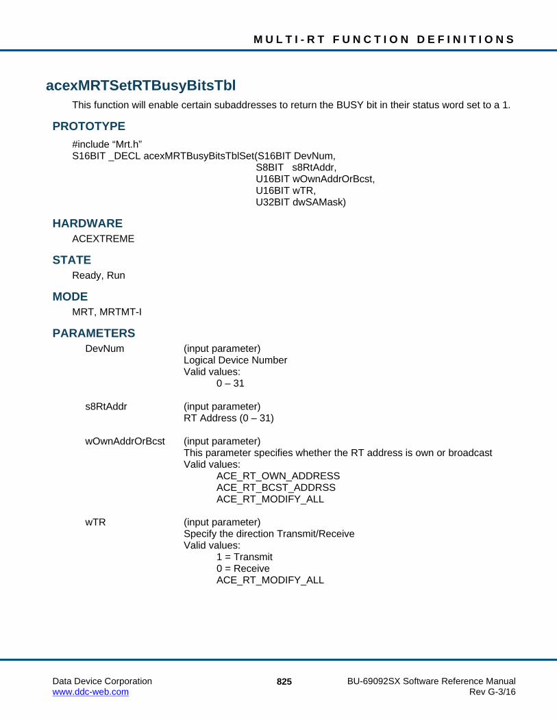
M U L T I - R T F U N C T I O N D E F I N I T I O N S
Data Device Corporation BU-69092SX Software Reference Manual www.ddc-web.com Rev G-3/16
825
acexMRTSetRTBusyBitsTbl This function will enable certain subaddresses to return the BUSY bit in their status word set to a 1.
PROTOTYPE #include “Mrt.h” S16BIT _DECL acexMRTBusyBitsTblSet(S16BIT DevNum, S8BIT s8RtAddr, U16BIT wOwnAddrOrBcst, U16BIT wTR, U32BIT dwSAMask)
HARDWARE ACEXTREME
STATE Ready, Run
MODE MRT, MRTMT-I
PARAMETERS DevNum (input parameter) Logical Device Number Valid values: 0 – 31 s8RtAddr (input parameter) RT Address (0 – 31) wOwnAddrOrBcst (input parameter)
This parameter specifies whether the RT address is own or broadcast Valid values: ACE_RT_OWN_ADDRESS ACE_RT_BCST_ADDRSS ACE_RT_MODIFY_ALL wTR (input parameter) Specify the direction Transmit/Receive Valid values: 1 = Transmit 0 = Receive ACE_RT_MODIFY_ALL

M U L T I - R T F U N C T I O N D E F I N I T I O N S
Data Device Corporation BU-69092SX Software Reference Manual www.ddc-web.com Rev G-3/16
826
acexMRTSetRTBusyBitsTbl (continued) dwSAMask (input parameter)
An unsigned 32-bit packed value that represents the subaddresses that should respond with the BUSY bit set in the status word. A ‘1’ indicates the BUSY bit should be active. The value is an OR’ed combination of the following values.
Valid value: ACE_RT_SAXX Specifies the subaddress where XX = 0 – 31 ACE_RT_SA_ALL Selects all subaddresses
DESCRIPTION This function will enable certain subaddresses to return the BUSY bit in their status words set. The table is set based on the type of message as defined by the following parameters: Own Address/Bcst* T/R*. Using the ACE_RT_MODIFY_ALL constant will set the status word BUSY BIT for all messages of a certain type. In conjunction with this you can use the ACE_RT_SA_ALL constant to make all subaddresses respond with the busy bit set.
RETURN VALUE ACE_ERR_SUCCESS The function completed successfully ACE_ERR_INVALID_DEVNUM An invalid device number was input by the user ACE_ERR_INVALID_STATE The device is not in a Ready or Run state ACE_ERR_PARAMETER The wTR and/or the wOwnAddrOrBcst input
parameter(s) contain an incorrect value
EXAMPLE S16BIT DevNum = 0; S16BIT nResult = 0; S8BIT s8RtAddr = 1; U16BIT wOwnAddrOrBcst = 1, wTR = 1; U32BIT dwSAMask = ACE_RT_SA0 | ACE_RT_SA22 | ACE_RT_SA25; nResult = acexMRTSetRTBusyBitsTbl(DevNum, s8RtAddr, wOwnAddrOrBcst, wTR, wSAMask); if(nResult) { printf(“Error in acexMRTSetBusyBitsTbl() function \n”); PrintOutError(nResult); return; }

M U L T I - R T F U N C T I O N D E F I N I T I O N S
Data Device Corporation BU-69092SX Software Reference Manual www.ddc-web.com Rev G-3/16
827
acexMRTBusyBitsTblSet (continued) SEE ALSO
aceRTBusyBitsTblClear() aceRTBusyBitsTblStatus()

M U L T I - R T F U N C T I O N D E F I N I T I O N S
Data Device Corporation BU-69092SX Software Reference Manual www.ddc-web.com Rev G-3/16
828
acexMRTSetRTStatusBits This function will set the status bits for all RT responses.
PROTOTYPE #include “mrt.h” S16BIT _DECL acexMRTSetRTStatusBits(S16BIT DevNum, S8BIT s8RtAddr, U16BIT wStatusBits);
HARDWARE ACEXTREME
STATE Ready, Run
MODE MRT, MRTMT-I
PARAMETERS DevNum (input parameter) Logical Device Number Valid values: 0 – 31 s8RtAddr (input parameter) RT Address (0 – 31) wStatusBits (output parameter)
Pointer to an unsigned 16-bit value that represents the bits in the RT Status Word. The following mask values can be used to represent the bit values.
Valid values: ACE_RT_STSBIT_DBCA ACE_RT_STSBIT_BUSY ACE_RT_STSBIT_SREQ ACE_RT_STSBIT_SSFLAG ACE_RT_STSBIT_RTFLAG
DESCRIPTION This function sets the status bits for all RT responses. Some of the status bits will only be available when in ‘Alternate Status Word’ mode. These are designated in the parameter descriptions.

M U L T I - R T F U N C T I O N D E F I N I T I O N S
Data Device Corporation BU-69092SX Software Reference Manual www.ddc-web.com Rev G-3/16
829
acexMRTSetRTStatusBits (continued) RETURN VALUE
ACE_ERR_SUCCESS The function completed successfully ACE_ERR_INVALID_DEVNUM An invalid device number was input by the user ACE_ERR_INVALID_STATE The device is not in a Ready or Run state
EXAMPLE S16BIT DevNum = 0; S16BIT nResult = 0; S8BIT s8RtAddr = 1; U16BIT wStatusBits = ACE_RT_STSBIT_BUSY; /* Configure the RT Status word response status to respond with the Busy bit set */ nResult = acexMRTSetRTStatusBits(DevNum,s8RtAddr,&wStatusBits); if(nResult) { printf(“Error in acexMRTSetRTStatusBits() function\n”); PrintOutError(nResult); return; }
SEE ALSO acexMRTClearRTStatusBits() acexMRTGetRTStatusBits()

M U L T I - R T F U N C T I O N D E F I N I T I O N S
Data Device Corporation BU-69092SX Software Reference Manual www.ddc-web.com Rev G-3/16
830
acexMRTStart This function starts a single RT or all enabled RTs.
PROTOTYPE #include “mrt.h” S16BIT _DECL acexMRTStart(S16BIT DevNum, S8BIT s8RtAddr, U32 u32Options);
HARDWARE AceXtreme
STATE Ready
MODE MRT, MRTMT-I
PARAMETERS DevNum (input parameter) Logical Device Number Valid values: 0 – 31 s8RtAddr (input parameter) RT Address (0 – 31) or -1 to start all enabled RTs U32Options (input parameter) ACEX_MRT_OPT_RESET_CMDSTK Use this option to reset the RT Cmd Stack before starting the
RT(s). This features is available primarily to support Single RT compatibility mode.
DESCRIPTION This function sets up all required registers, sets up enhanced mode code handling, and then starts the enabled Remote Terminals. The enabled Remote Terminals will respond to messages on the 1553 bus. The device will transition from a Ready state to a Run state after this function has been called.
RETURN VALUE ACE_ERR_SUCCESS The function completed successfully ACE_ERR_INVALID_DEVNUM An invalid device number was input by the user ACE_ERR_INVALID_STATE The device is not in a Ready state ACE_ERR_OPERATION Hardware does not support Multi-RT mode ACE_ERR_PARAMETER s8RtAddr was not configured correctly.

M U L T I - R T F U N C T I O N D E F I N I T I O N S
Data Device Corporation BU-69092SX Software Reference Manual www.ddc-web.com Rev G-3/16
831
acexMRTStart (continued) EXAMPLE
S16BIT DevNum = 0; S16BIT nResult = 0; /* Initialize the device, create the Data Blocks, Map the Data Blocks, and setup legalization, then call acexMRTStart() */ nResult = acexMRTStart(DevNum, -1, 0); if(nResult) { printf(“Error in acexMRTStart() function \n”); PrintOutError(nResult); return; }
SEE ALSO aceRTStop()

M U L T I - R T F U N C T I O N D E F I N I T I O N S
Data Device Corporation BU-69092SX Software Reference Manual www.ddc-web.com Rev G-3/16
832
acexMRTStop This function stops the RT.
PROTOTYPE #include “Mrt.h” S16BIT _DECL acexMRTStop(S16BIT DevNum, S8BIT s8RtAddr);
HARDWARE ACEXTREME
STATE Run
MODE MRT, MRTMT-I
PARAMETERS DevNum (input parameter) Logical Device Number Valid values: 0 – 31 s8RtAddr (input parameter) RT Address (0 – 31) or -1 to stop all enabled RTs.
DESCRIPTION This function stops the Remote Terminal from responding to messages on the 1553 bus. The device will transition from a Run state to a Ready state after this function has been called.
RETURN VALUE ACE_ERR_SUCCESS The function completed successfully ACE_ERR_INVALID_DEVNUM An invalid device number was input by the user ACE_ERR_INVALID_STATE The device is not in a Ready state ACE_ERR_OPERATION Hardware does not support Multi-RT mode ACE_ERR_PARAMETER s8RtAddr was not configured correctly

M U L T I - R T F U N C T I O N D E F I N I T I O N S
Data Device Corporation BU-69092SX Software Reference Manual www.ddc-web.com Rev G-3/16
833
acexMRTStop (continued) EXAMPLE
S16BIT DevNum = 0; S16BIT nResult = 0; /* Initialize the device, create the Data Blocks, Map the Data Blocks, and setup legalization. Start the RT and perform appropriate data processing then call acexMRTStop() */ nResult = acexMRTStop(DevNum, -1); if(nResult) { printf(“Error in acexMRTStop() function \n”); PrintOutError(nResult); return; }
SEE ALSO acexMRTStart()

M U L T I - R T F U N C T I O N D E F I N I T I O N S
Data Device Corporation BU-69092SX Software Reference Manual www.ddc-web.com Rev G-3/16
834
acexMRTImrTrigSelect This function assigns a discrete I/O pin for input trigger intermessage routine.
PROTOTYPE #include “mrt.h” S16BIT _DECL acexMRTImrTrigSelect(S16BIT DevNum, U16BIT u16Select);
HARDWARE Multi-Function AceXtreme
STATE Reset, Ready
MODE Not Applicable
PARAMETERS DevNum (input parameter) Logical Device Number Valid values: 0 – 31 u16Select (input parameter) The actual number of Discrete I/O available varies with the hardware Valid values: DIO_1, DIO_2…
DESCRIPTION This function assigns a discrete I/O pin for input trigger intermessage routine.
RETURN VALUE ACE_ERR_INVALID_DEVNUM An invalid device number was input by the user ACE_ERR_SUCCESS The function completed successfully
EXAMPLE S16BIT DevNum = 0; S16BIT nResult = 0;
//Assign a discrete I/O pin for IMRS. nResult = acexMRTImrTrigSelect(DevNum, DIO_1); if(nResult < 0) { printf(“Error in acexMRTImrTrigSelect() function \n”); return; }

M U L T I - R T F U N C T I O N D E F I N I T I O N S
Data Device Corporation BU-69092SX Software Reference Manual www.ddc-web.com Rev G-3/16
835
acexMRTImrTrigSelect (continued) SEE ALSO
acexTRGEnable() acexTRGDisable() acexTRGConfigure() acexTRGEventEnable() acexTRGEventDisable() acexTRGEventSelect() acexTRGGetTimeTag() acexTRGGetStatus()

M U L T I - R T F U N C T I O N D E F I N I T I O N S
Data Device Corporation BU-69092SX Software Reference Manual www.ddc-web.com Rev G-3/16
836
acexMRTWriteRTBITWrd This function will write a BIT word to the external BIT word location.
PROTOTYPE #include “Mrt.h” S16BIT _DECL acexMRTWriteRTBITWrd(S16BIT DevNum, S8BIT s8RtAddr, U16BIT *wBITWrd);
HARDWARE AceXtreme
STATE Ready, Run
MODE MRT, MRTMT-I
PARAMETERS DevNum Logical Device Number Valid values: 0 – 31 s8RtAddr (input parameter) RT Address (0 – 31) or -1 to start all enabled RTs. wBITWrd (input parameter)
Pointer to an unsigned 16-bit value that will be written into the external BIT word location. The individual bit descriptions are given below. A 1 will represent the condition shown for the bit.
Valid values: Bit 15 Transmitter Timeout Set if the 1553 hardware failsafe timer detected a fault condition.
The transmitter timeout circuit will automatically shut down the CH. A or CH. B transmitter if it transmits for longer than 668 µs. In RT mode, the 1553 hardware will terminate the processing of the current message as the result of a transmitter timeout, however, it will respond to the next message received.

M U L T I - R T F U N C T I O N D E F I N I T I O N S
Data Device Corporation BU-69092SX Software Reference Manual www.ddc-web.com Rev G-3/16
837
acexMRTWriteRTBITWrd (continued) Bit 14, 13 Loop Test Failure B, Loop Test Failure A A loopback test is performed on the transmitted portion of every
non-broadcast message. A validity check is performed on the received version of every word transmitted by the 1553 hardware. In addition, a bit-by-bit comparison is performed on the last word transmitted by the RT for each message. If either the received version of any transmitted word is determined to be invalid (sync, encoding, bit count, or parity error) and/or the received version of the last transmitted word does not match the transmitted version, or a failsafe timeout occurs on the respective channel, the Loop Test Failure bit for the respective bus channel will be set.
Bit 12 Handshake Failure If this bit is set, it indicates that the subsystem has failed to respond
with the DMA handshake input DTGRT* asserted within the allotted time, in response to the 1553 hardware asserting DTREQ*. Alternatively, a handshake failure will occur if the host PROCESSOR fails to clear STRBD* (high) within the allotted time, after the hardware has asserted its READYD* output (low). The allotted time is 4 µs for a 16 MHz clock, or 3.5 µs for a 12 MHz clock. All of DDC’s 1553 COTS cards provide a 16 MHz clock.
Bit 11, Bit 10 Transmitter Shutdown B, Transmitter Shutdown A Indicates that the transmitter on the respective bus channel has
been shut down by a Transmitter shutdown mode code command received on the alternate channel. If an Override transmitter shutdown mode code command is received on the alternate channel, this bit will revert back to logic 0.
Bit 9 Terminal Flag Inhibited Set to logic 1 if the Terminal Flag RT Status bit has been disabled
by an Inhibit terminal flag mode code command. Will revert to logic 0 if an Override inhibit terminal flag mode code command is received.

M U L T I - R T F U N C T I O N D E F I N I T I O N S
Data Device Corporation BU-69092SX Software Reference Manual www.ddc-web.com Rev G-3/16
838
acexMRTWriteRTBITWrd (continued) Bit 8 Bit Test Fail Represents the result of the RT’s most recent built-in protocol self-
test. A value of logic 0 for bit 8 indicates that the test passed. The bit will return a value of logic 1 if the 1553 hardware has failed its most recent protocol self-test. If a subsequent performing of the protocol self-test passes, bit 8 will clear to 0. Also, note that the RAM self-test has no effect on bit 8.
Bit 7 High Word Count Set to logic 1 if the most recent message had a high word count
error. Bit 6 Low Word Count Set to logic 1 if the most recent message had a low
word count error. Bit 5 Incorrect Sync Received Set to a logic 1 if the 1553 hardware detected a Command sync in
a received Data Word. Bit 4 Invalid Word Received Indicates that the RT received a Data Word containing one or more
of the following error types: sync field error, Manchester encoding error, parity error, and/or bit count error.
Bit 3 RT-RT Gap/Sync/Address Error This bit is set if the RT is the receiving RT for an RT to RT transfer
and one or more of the following occurs: (1) If the GAP CHECK ENABLED bit (bit 8) of Configuration Register # 5 at memory location 0x09 is set to logic 1 and the transmitting RT responds with a response time of less than 4 µs, per MIL-STD-1553B (mid-parity bit to mid-sync); i.e., less than 2 µs dead time; and/or (2) There is an incorrect sync type or format error (encoding, bit count, and/or parity error) in the transmitting RT Status Word; and/or (3) The RT address field of the transmitting RT Status Word does not match the RT address in the transmit Command Word.

M U L T I - R T F U N C T I O N D E F I N I T I O N S
Data Device Corporation BU-69092SX Software Reference Manual www.ddc-web.com Rev G-3/16
839
acexMRTWriteRTBITWrd (continued) Bit 2 RT-RT No Response Error If this bit is set to a logic 1, this indicates that for the previous
message, the 1553 hardware was the receiving RT for an RT to RT transfer and that the transmitting RT either did not respond or responded later than the RT to RT Timeout time. The RT to RT Response Timeout Time is defined as the time from the mid-bit crossing of the
parity bit of the transmit Command Word to the mid-sync crossing of the transmitting RT Status Word. The value of the RT to RT Response Timeout is 18.5 µs by default, or programmable from among nominal values of 18.5, 22.5, 50.5, or 130 µs by calling the aceSetRespTimeOut() function.
Bit 1 RT-RT 2nd Command Word Error If the 1553 hardware is the receiving RT for an RT to RT transfer,
this bit set to a logic 1 indicates one or more of the following error conditions in the transmit Command Word: (1) T/R bit = logic "0"; (2) subaddress = 00000 or 11111; (3) same RT address field as the receive Command Word.
Bit 0 Command Word Contents Error Indicates a received command word is not defined in accordance
with MIL-STD-1553B specifications. This includes the following undefined Command Words: (1) BROADCAST DISABLED, bit 7 of Configuration Register # 5 at memory location 0x09 is logic 0 and the Command Word is a non-mode code, broadcast, or transmit command; (2) The OVERRIDE MODE T/R* ERROR bit, bit 6 of Configuration Register # 3 at memory location 0x07 is logic 0 and a message with a T/R* bit of 0, a subaddress/mode field of 00000 or 11111 and a mode code field between 00000 and 01111; (3) BROADCAST DISABLED, bit 7 of Configuration Register # 5 is logic 0 and a mode code command that is not permitted to be broadcast (e.g., Transmit status) is sent to the broadcast address (11111).
DESCRIPTION This function writes the BIT word if set as external. External BIT word is written to the memory location that the transmit Mode BIT word mode code data would be stored (hardware mode code memory offset + 0x13). If the location is configured as internal, this function will return ACE_ERR_PARAMETER.

M U L T I - R T F U N C T I O N D E F I N I T I O N S
Data Device Corporation BU-69092SX Software Reference Manual www.ddc-web.com Rev G-3/16
840
acexMRTWriteRTBITWrd (continued) RETURN VALUE
ACE_ERR_SUCCESS The function completed successfully ACE_ERR_INVALID_DEVNUM An invalid device number was input by the user ACE_ERR_INVALID_STATE The device is not in a Ready or Run state ACE_ERR_PARAMETER The BIT location has been configured as
ACE_RT_BIT_INTERNAL
EXAMPLE S16BIT DevNum = 0; S16BIT nResult = 0; S8BIT s8RTAddr = 11; U16BIT wBITWrd = 0x5555; // Write External BIT. The BIT word configuration must specify External nResult = acexMRTWriteRTBITWrd(DevNum, s8RtAddr, &wBITWrd); if(nResult) { printf(“Error in acexMRTWriteRTBITWrd() function \n”); PrintOutError(nResult); return; }
SEE ALSO aceRTBITWrdConfig() aceRTBITWrdRead()

M U L T I - R T F U N C T I O N D E F I N I T I O N S
Data Device Corporation BU-69092SX Software Reference Manual www.ddc-web.com Rev G-3/16
841
acexMRTWriteRTModeCodeData This function will write to the Enhanced Mode Code Data Locations table.
PROTOTYPE #include “Mrt.h” S16BIT _DECL acexMRTWriteRTModeCodeData(S16BIT DevNum, S8BIT s8RtAddr, U16BIT wModeCode, U16BIT wMCData);
HARDWARE AceXtreme
STATE Ready, Run
MODE MRT, MRTMT-I
PARAMETERS DevNum (input parameter) Logical Device Number Valid values: 0 – 31 s8RtAddr (input parameter) RT Address (0 – 31) wModeCode (input parameter)
This parameter specifies which mode code contains the data that should be read
Valid values: ACE_RT_MCDATA_RX_SYNCHRONIZE ACE_RT_MCDATA_RX_SEL_T_SHUTDWN ACE_RT_MCDATA_RX_OVR_SEL_T_SHUTDWN ACE_RT_MCDATA_TX_TRNS_VECTOR ACE_RT_MCDATA_TX_TRNS_LAST_CMD ACE_RT_MCDATA_TX_TRNS_BIT ACE_RT_MCDATA_BCST_SYNCHRONIZE ACE_RT_MCDATA_BCST_SEL_T_SHUTDWN ACE_RT_MCDATA_BCST_OVR_SEL_T_SHUTDWN wMCData (output parameter)
A single unsigned 16-bit piece of data returned from the Mode Code data table

M U L T I - R T F U N C T I O N D E F I N I T I O N S
Data Device Corporation BU-69092SX Software Reference Manual www.ddc-web.com Rev G-3/16
842
acexMRTWriteRTModeCodeData (continued) DESCRIPTION
This function will write data to the specified Mode Code data table. The mode code for which data is to be written is specified by wModeCode. The data written will be a single U16BIT word that is written to the Mode Code data table.
RETURN VALUE ACE_ERR_SUCCESS The function completed successfully ACE_ERR_INVALID_DEVNUM An invalid device number was input by the user ACE_ERR_INVALID_STATE The device is not in a Ready or Run state ACE_ERR_INVALID_MODE The device is not in RT or RTMT mode ACE_ERR_PARAMETER The wModeCode parameter
EXAMPLE S16BIT DevNum = 0; S8BIT s8RtAddr = 1; U16BIT wMCData = 0x4DDC; /*Read the data that is associated with the ACE_RT_MCDATA_TX_TRNS_BIT mode code. */ nResult = acexMRTWriteRTModeCodeData(DevNum, s8RtAddr, ACE_RT_MCDATA_TX_TRNS_BIT, wMCData); if(nResult) { printf(“Error in acexMRTWriteRTModeCodeWrite() function \n”); PrintOutError(nResult); return; }
SEE ALSO aceRTModeCodeReadData()

Data Device Corporation BU-69092SX Software Reference Manual www.ddc-web.com Rev G-3/16
843
4.9 Avionics I/O Functions
Table 11. Avionics I/O Functions Listing
Function Page
aceGetAioAll 844
aceGetAioDir 846
aceGetAioIn 848
aceGetAioOut 850
aceSetAioAll 852
aceSetAioDir 854
aceSetAioOut 856

A V I O N I C S I / O F U N C T I O N D E F I N I T I O N S
Data Device Corporation BU-69092SX Software Reference Manual www.ddc-web.com Rev G-3/16
844
aceGetAioAll This function gets the directions and levels of all avionic I/O channels.
PROTOTYPE #include “aioOp.h” S16BIT _DECL aceGetAioAll (S16BIT DevNum, U16BIT *Direction, U16BIT *Levels);
HARDWARE AceXtreme
STATE Ready, Run
MODE Not Applicable
PARAMETERS DevNum (input parameter) Logical Device Number Valid values: 0 - 31 Direction (output parameter) Bitwise representation of the direction of avionic line, 0 is for input and 1 is for output. Bit 0 is the LSB and Bit 15 is the MSB. Levels (output parameter) Bitwise representation of the level of avionic line, 0 is for LOW and 1 is for HIGH. Bit 0 is the LSB and Bit 15 is the MSB.
DESCRIPTION This function returns current state of all the avionic I/Os on your DDC card. This function can only be used with supporting DDC Hardware.
RETURN VALUE ACE_ERR_SUCCESS The function completed successfully ACE_ERR_INVALID_DEVNUM An invalid device number was used ACE_ERR_INVALID_STATE The device is not a Ready or Run State ACE_ERR_INVALID_CARD The device does not support this function ACE_ERR_NOT_SUPPORTED Function is not supported

A V I O N I C S I / O F U N C T I O N D E F I N I T I O N S
Data Device Corporation BU-69092SX Software Reference Manual www.ddc-web.com Rev G-3/16
845
aceGetAioAll (continued) EXAMPLE
S16BIT DevNum = 0; S16BIT nResult = 0; U16BIT Direction = 0; U16BIT Levels = 0; nResult = aceGetAioAll (DevNum, &Direction, &Levels); if (nResult < 0) { printf(“Error in aceGetAioAll() function \n”); PrintOutError (nResult); return; }
SEE ALSO aceGetAioIn() aceGetAioOut() aceSetAioAll() aceSetAioDir() aceSetAioOut() aceGetAioDir()

A V I O N I C S I / O F U N C T I O N D E F I N I T I O N S
Data Device Corporation BU-69092SX Software Reference Manual www.ddc-web.com Rev G-3/16
846
aceGetAioDir This function gets the direction of one of the avionics I/O channels.
PROTOTYPE #include “aioOp.h” S16BIT _DECL aceGetAioDir (S16BIT DevNum, S16BIT Channel);
HARDWARE AceXtreme
STATE Ready, Run
MODE Not Applicable
PARAMETERS DevNum (input parameter) Logical Device Number Valid values: 0 - 31 Channel (input parameter) Indicates which avionics channel to check.
DESCRIPTION This function gets the direction of one of the avionics I/O channels on your DDC Device. This function requires supporting DDC hardware.
RETURN VALUE ACE_ERR_INVALID_DEVNUM An invalid device number was input by the user ACE_ERR_INVALID_STATE The device is not a Ready or Run State ACE_ERR_INVALID_CARD The device is not a BU-65567CX or BU-65568CX card ACE_ERR_AVIONIC Invalid avionic bit specified ACE_ERR_NOT_SUPPORTED Function is not supported NUMBER A 0 represents the avionic is set as an input while a 1
means the avionic is configured as an output

A V I O N I C S I / O F U N C T I O N D E F I N I T I O N S
Data Device Corporation BU-69092SX Software Reference Manual www.ddc-web.com Rev G-3/16
847
aceGetAioDir (continued) EXAMPLE
S16BIT DevNum = 0; S16BIT nResult = 0; Channel = 1; nResult = aceGetAioDir (DevNum, Channel); if (nResult < 0) { printf(“Error in aceGetAioDir() function \n”); PrintOutError (nResult); return; }
SEE ALSO aceGetAioIn() aceGetAioOut() aceSetAioAll() aceSetAioDir() aceSetAioOut() aceGetAioAll()

A V I O N I C S I / O F U N C T I O N D E F I N I T I O N S
Data Device Corporation BU-69092SX Software Reference Manual www.ddc-web.com Rev G-3/16
848
aceGetAioIn This function gets the input level of one of the avionics I/O channels.
PROTOTYPE #include “aioOp.h” S16BIT _DECL aceGetAioIn (S16BIT DevNum, S16BIT Channel);
HARDWARE AceXtreme
STATE Ready, Run
MODE Not Applicable
PARAMETERS DevNum (input parameter) Logical Device Number Valid values: 0 - 31 Channel (input parameter) Indicates which avionics channel to check.
DESCRIPTION This function gets the input level of one of the avionics I/O channels on your DDC card. This function can only be used with supporting DDC Hardware.
RETURN VALUE ACE_ERR_INVALID_DEVNUM An invalid device number was used ACE_ERR_INVALID_STATE The device is not a Ready or Run State ACE_ERR_INVALID_CARD The device does not support this function ACE_ERR_AVIONIC Invalid avionic bit specified ACE_ERR_NOT_SUPPORTED Function is not supported NUMBER A 0 represents the avionic level is LOW while a 1 means the
avionic level is HIGH

A V I O N I C S I / O F U N C T I O N D E F I N I T I O N S
Data Device Corporation BU-69092SX Software Reference Manual www.ddc-web.com Rev G-3/16
849
aceGetAioIn(continued) EXAMPLE
S16BIT DevNum = 0; S16BIT nResult = 0; S16BIT Discrete = DIO_1; nResult = aceGetAioIn(DevNum, Discrete); if (nResult < 0) { printf(“Error in aceGetAioIn() function \n”); PrintOutError (nResult); return; }
SEE ALSO aceGetAioAll() aceGetAioOut() aceSetAioAll() aceSetAioDir() aceSetAioOut() aceGetAioDir()

A V I O N I C S I / O F U N C T I O N D E F I N I T I O N S
Data Device Corporation BU-69092SX Software Reference Manual www.ddc-web.com Rev G-3/16
850
aceGetAioOut This function gets the output level of one of the avionics I/O channels.
PROTOTYPE #include “aioOp.h” S16BIT _DECL aceGetAioOut (S16BIT DevNum, S16BIT Channel);
HARDWARE AceXtreme
STATE Ready, Run
MODE Not Applicable
PARAMETERS DevNum (input parameter) Logical Device Number Valid values: 0 - 31 Channel (input parameter) Indicates which avionics channel to check.
DESCRIPTION This function gets the output level of one of the avionics I/O channels on your DDC device based on the value of the avionic input parameter. This function requires supporting DDC hardware.
RETURN VALUE ACE_ERR_INVALID_DEVNUM An invalid device number ACE_ERR_INVALID_STATE The device is not a Ready or Run State ACE_ERR_INVALID_CARD The device does not support this function ACE_ERR_NOT_SUPPORTED Function is not supported ACE_ERR_DISCRETE Invalid avionic bit specified NUMBER A 0 represents the avionic level is LOW while a 1 means the
avionic level is HIGH

A V I O N I C S I / O F U N C T I O N D E F I N I T I O N S
Data Device Corporation BU-69092SX Software Reference Manual www.ddc-web.com Rev G-3/16
851
aceGetAioOut (continued) EXAMPLE
S16BIT DevNum = 0; S16BIT nResult = 0; S16BIT Channel = 1; nResult = aceGetAioOut (DevNum, Channel); if (nResult < 0) { printf(“Error in aceGetAioDir() function \n”); PrintOutError (nResult); return; }
SEE ALSO aceGetAioIn() aceGetAioAll() aceSetAioAll() aceSetAioDir() aceSetAioOut() aceGetAioDir()

A V I O N I C S I / O F U N C T I O N D E F I N I T I O N S
Data Device Corporation BU-69092SX Software Reference Manual www.ddc-web.com Rev G-3/16
852
aceSetAioAll This function sets the directions and levels of all avionics I/O channels simultaneously.
PROTOTYPE #include “aioOp.h” S16BIT _DECL aceSetAioAll (S16BIT DevNum, U16BIT Directions, U16BIT Levels);
HARDWARE EMACE, E²MA, AceXtreme
STATE Ready, Run
MODE Not Applicable
PARAMETERS DevNum (input parameter) Logical Device Number Valid values: 0 - 31 Direction (output parameter) Bitwise representation of the direction of Avionics line, 0 is for input and 1 is for output. Bit 8 is the LSB and Bit 15 is the MSB. Levels (output parameter) Bitwise representation of the level of avionic line, 0 is for low and 1 is for high. Bit 0 is the LSB and Bit 7 is the MSB.
DESCRIPTION This function sets the directions and levels of all avionics I/O channels simultaneously on your DDC card based on the value of the Level input parameter. This function can only be used with supporting DDC Hardware.
RETURN VALUE ACE_ERR_SUCCESS The function completed successfully ACE_ERR_INVALID_DEVNUM An invalid device number was input by the user ACE_ERR_INVALID_STATE The device does not support this function ACE_ERR_INVALID_CARD The device is not a BU-65567CX or BU-65568CX ACE_ERR_NOT_SUPPORTED Function is not supported

A V I O N I C S I / O F U N C T I O N D E F I N I T I O N S
Data Device Corporation BU-69092SX Software Reference Manual www.ddc-web.com Rev G-3/16
853
aceSetAioAll (continued) EXAMPLE
S16BIT DevNum = 0; S16BIT nResult = 0; U16BIT Directions = 0x02; U16BIT Levels = 0x02; nResult = aceSetAioAll (DevNum, Directions, Levels); If (nResult < 0) { printf(“Error in aceSetAioAll() function \n”); PrintOutError (nResult); return; }
SEE ALSO aceGetAioIn() aceGetAioOut() aceGetAioAll() aceSetAioDir() aceSetAioOut() aceGetAioDir()

A V I O N I C S I / O F U N C T I O N D E F I N I T I O N S
Data Device Corporation BU-69092SX Software Reference Manual www.ddc-web.com Rev G-3/16
854
aceSetAioDir This function sets the direction of one of the avionics I/O channels.
PROTOTYPE #include “aioOp.h” S16BIT DECL aceSetAioDir(S16BIT DevNum, S16BIT Channel, AVIONIC_DIR Direction);
HARDWARE EMACE, E²MA, AceXtreme
STATE Ready, Run
MODE Not Applicable
PARAMETERS DevNum (input parameter) Logical Device Number Valid values: 0 - 31 Channel (input parameter) Indicates which avionic channel to check Direction (input parameter) Valid values: AVIONIC_INPUT = 0 AVIONIC_OUTPUT = 1
DESCRIPTION This function sets the direction of one of the avionics I/O channels on your DDC Device. This function requires supporting DDC hardware.
RETURN VALUE ACE_ERR_SUCCESS The function completed successfully ACE_ERR_INVALID_DEVNUM An invalid device number was input by the user ACE_ERR_INVALID_STATE The device does not support this function ACE_ERR_INVALID_CARD The device is not a BU-65567CX or BU-65568CX

A V I O N I C S I / O F U N C T I O N D E F I N I T I O N S
Data Device Corporation BU-69092SX Software Reference Manual www.ddc-web.com Rev G-3/16
855
aceSetAioDir (continued) EXAMPLE
S16BIT DevNum = 0; S16BIT nResult = 0; S16BIT Channel; Channel = 1; nResult = aceSetAioDir (DevNum, Channel, AVIONIC_INPUT); If (nResult < 0) { printf(“Error in aceSetAioDir() function \n”); PrintOutError (nResult); return; }
SEE ALSO aceGetAioIn() aceGetAioOut() aceSetAioAll() aceGetAioAll() aceSetAioOut() aceGetAioDir()

A V I O N I C S I / O F U N C T I O N D E F I N I T I O N S
Data Device Corporation BU-69092SX Software Reference Manual www.ddc-web.com Rev G-3/16
856
aceSetAioOut This function sets the output level of one of the avionics I/O channels.
PROTOTYPE #include “aioOp.h” S16BIT DECL aceSetAioOut(S16BIT DevNum, S16BIT Channel, AVIONIC_LEVEL Level);
HARDWARE EMACE, E²MA, AceXtreme
STATE Ready, Run
MODE Not Applicable
PARAMETERS DevNum (input parameter) Logical Device Number Valid values: 0 - 31 Channel (input parameter) Indicates which avionic channel to check Valid values: AIO_OUT1 to AIO_OUT8 Level (input parameter) Valid values: AVIONIC_LOW = 0 AVIONIC_HIGH = 1
DESCRIPTION This function sets the output level of one of the avionics I/O channels on your DDC device based on the value of the Channel input parameter. This function requires supporting DDC hardware.
RETURN VALUE ACE_ERR_SUCCESS The function completed successfully ACE_ERR_INVALID_DEVNUM An invalid device number was input by the user ACE_ERR_INVALID_STATE The device does not support this function ACE_ERR_INVALID_CARD The device is not a BU-65567CX or BU-65568CX

A V I O N I C S I / O F U N C T I O N D E F I N I T I O N S
Data Device Corporation BU-69092SX Software Reference Manual www.ddc-web.com Rev G-3/16
857
aceSetAioOut (continued) example S16BIT DevNum = 0; S16BIT nResult = 0; S16BIT Channel; Channel = AIO_OUT1; //set port 1 nResult = aceSetAioOut (DevNum, Channel, AVIONIC_LOW); if (nResult < 0) { printf(“Error in aceSetAioOut() function \n”); PrintOutError (nResult); return; }
SEE ALSO aceGetAioIn() aceGetAioOut() aceSetAioAll() aceSetAioDir() aceGetAioAll() aceGetAioDir()

Data Device Corporation BU-69092SX Software Reference Manual www.ddc-web.com Rev G-3/16
858
4.10 Discrete I/O Functions
Table 12. Discrete I/O Functions Listing
Function Page aceGetDiscAll 859
aceGetDiscDir 861
aceGetDiscIn 863
aceGetDiscOut 865
aceSetDiscAll 867
aceSetDiscDir 869
aceSetDiscOut 871

D I S C R E T E I / O F U N C T I O N D E F I N I T I O N S
Data Device Corporation BU-69092SX Software Reference Manual www.ddc-web.com Rev G-3/16
859
aceGetDiscAll This function retrieves the current state of all of the discrete I/Os on your DDC Device.
PROTOTYPE #include “Dio.h” S16BIT _DECL aceGetDiscAll (S16BIT DevNum, U16BIT *Direction, U16BIT *Levels);
HARDWARE AceXtreme
STATE Ready, Run
MODE Not Applicable
PARAMETERS DevNum (input parameter) Logical Device Number Valid values: 0 – 31 Direction (output parameter) Bitwise representation of the direction of discrete, 0 is for INPUT and 1 is for OUTPUT. Bit 0 is the LSB and Bit 15 is the MSB Levels (output parameter) Bitwise representation of the level of discrete, 0 is for LOW and 1 is for HIGH. Bit 0 is the LSB and Bit 15 is the MSB.
DESCRIPTION This function returns the current state of all the discrete I/Os on your DDC card. This function can only be used with supporting DDC Hardware.
RETURN VALUE ACE_ERR_SUCCESS The function completed successfully ACE_ERR_INVALID_DEVNUM An invalid device number was used ACE_ERR_INVALID_STATE The device is not a Ready or Run State ACE_ERR_INVALID_CARD The device does not support this function ACE_ERR_PARAMETER Invalid parameter ACE_ERR_NOT_SUPPORTED Function is not supported

D I S C R E T E I / O F U N C T I O N D E F I N I T I O N S
Data Device Corporation BU-69092SX Software Reference Manual www.ddc-web.com Rev G-3/16
860
aceGetDiscAll (continued) EXAMPLE
S16BIT DevNum = 0; S16BIT nResult = 0; U16BIT Direction = 0; U16BIT Levels = 0; nResult = aceGetDiscAll(DevNum, &Direction, &Levels); If (nResult < 0) { printf(“Error in aceGetDiscAll() function \n”); PrintOutError (nResult); return; }
SEE ALSO aceGetDiscDir() aceGetDiscIn() aceGetDiscOut() aceSetDiscAll() aceSetDiscDir() aceSetDiscOut()

D I S C R E T E I / O F U N C T I O N D E F I N I T I O N S
Data Device Corporation BU-69092SX Software Reference Manual www.ddc-web.com Rev G-3/16
861
aceGetDiscDir This function returns the direction of the discrete I/O line on your DDC device.
PROTOTYPE #include “Dio.h” S16BIT _DECL aceGetDiscDir (S16BIT DevNum, S16BIT Discrete);
HARDWARE AceXtreme
STATE Ready, Run
MODE Not Applicable
PARAMETERS DevNum (input parameter) Logical Device Number Valid values: 0 – 31 Discrete (input parameter) The actual number of Discrete I/O available varies with the hardware Valid values: DIO_1, DIO_2…
DESCRIPTION This routine returns the direction of a discrete line on your DDC Device. This function requires supporting DDC hardware.
RETURN VALUE ACE_ERR_INVALID_DEVNUM An invalid device number was input by the user ACE_ERR_INVALID_STATE The device is not in a Ready or Run state ACE_ERR_INVALID_CARD The device is not a BU-65567CX or BU-65568CX
card ACE_ERR_DISCRETE Invalid discrete bit specified NUMBER: 0 or 1 A 0 represents the discrete is set as an INPUT
while a 1 means the discrete is configured as an OUTPUT

D I S C R E T E I / O F U N C T I O N D E F I N I T I O N S
Data Device Corporation BU-69092SX Software Reference Manual www.ddc-web.com Rev G-3/16
862
aceGetDiscDir (continued) EXAMPLE
S16BIT DevNum = 0; S16BIT nResult = 0; S16BIT Discrete; Discrete = DIO_1; //Read Discrete 1 nResult = aceGetDiscDir (DevNum, Discrete); If (nResult < 0) { printf(“Error in aceGetDiscDir() function \n”); PrintOutError (nResult); return; }
SEE ALSO aceGetDiscAll() aceGetDiscIn() aceGetDiscOut() aceSetDiscAll() aceSetDiscDir() aceSetDiscOut()

D I S C R E T E I / O F U N C T I O N D E F I N I T I O N S
Data Device Corporation BU-69092SX Software Reference Manual www.ddc-web.com Rev G-3/16
863
aceGetDiscIn This function retrieves the current state of one of the discrete inputs on your DDC Device.
PROTOTYPE #include “Dio.h” S16BIT _DECL aceGetDiscIn (S16BIT DevNum, S16BIT Discrete);
HARDWARE AceXtreme
STATE Ready, Run
MODE Not Applicable
PARAMETERS DevNum (input parameter) Logical Device Number Valid values: 0 – 31 Discrete (input parameter) The actual number of Discrete I/O available varies with the hardware Valid values: DIO_1, DIO_2…
DESCRIPTION This function returns the INPUT level of one of the discrete I/Os on your DDC card. This function can only be used with supporting DDC Hardware and if the discrete I/O is set as INPUT.
RETURN VALUE ACE_ERR_INVALID_DEVNUM An invalid device number was used ACE_ERR_INVALID_STATE The device is not in a Ready or Run state ACE_ERR_INVALID_CARD The device does not support this function ACE_ERR_DISCRETE Invalid discrete bit specified NUMBER: 0 or 1 A 0 represents the discrete is LOW while a 1 means the
discrete is HIGH

D I S C R E T E I / O F U N C T I O N D E F I N I T I O N S
Data Device Corporation BU-69092SX Software Reference Manual www.ddc-web.com Rev G-3/16
864
aceGetDiscIn (continued) EXAMPLE
S16BIT DevNum = 0; S16BIT nResult = 0; S16BIT Discrete; Discrete = DIO_1; nResult = aceGetDiscIn(DevNum, Discrete); If (nResult < 0) { printf(“Error in aceGetDiscIn() function \n”); PrintOutError (nResult); return; }
SEE ALSO aceGetDiscAll() aceGetDiscDir() aceGetDiscOut() aceSetDiscAll() aceSetDiscDir() aceSetDiscOut()

D I S C R E T E I / O F U N C T I O N D E F I N I T I O N S
Data Device Corporation BU-69092SX Software Reference Manual www.ddc-web.com Rev G-3/16
865
aceGetDiscOut This function will retrieve the current state of a discrete output on your DDC device.
PROTOTYPE #include “Dio.h” S16BIT _DECL aceGetDiscOut (S16BIT DevNum, S16BIT Discrete);
HARDWARE AceXtreme
STATE Ready, Run
MODE Not Applicable
PARAMETERS DevNum (input parameter) Logical Device Number Valid values: 0 – 31 Discrete (input parameter) The actual number of Discrete I/O available varies with the hardware Valid values: DIO_1, DIO_2…
DESCRIPTION This function retrieves the OUTPUT state of one of the discrete I/Os on your DDC device. This function can only be used with supporting DDC Hardware and if the discrete I/O is set as OUTPUT.
RETURN VALUE ACE_ERR_INVALID_DEVNUM An invalid device number ACE_ERR_INVALID_STATE The device is not in a Ready or Run state ACE_ERR_INVALID_CARD The device is not a BU-65567CX or BU-65568CX card ACE_ERR_DISCRETE Invalid discrete bit specified NUMBER: 0 or 1 A 0 represents the discrete output level is LOW while a 1
represents an output level of HIGH

D I S C R E T E I / O F U N C T I O N D E F I N I T I O N S
Data Device Corporation BU-69092SX Software Reference Manual www.ddc-web.com Rev G-3/16
866
aceGetDiscOut (continued) EXAMPLE
S16BIT DevNum = 0; S16BIT nResult = 0; S16BIT Discrete; Discrete = DIO_1; NResult = aceGetDiscOut(DevNum, Discrete); If (nResult < 0) { printf(“Error in aceGetDiscOut() function \n”); PrintOutError (nResult); return; }
SEE ALSO aceGetDiscAll() aceGetDiscDir() aceGetDiscIn() aceSetDiscAll() aceSetDiscDir() aceSetDiscOut()

D I S C R E T E I / O F U N C T I O N D E F I N I T I O N S
Data Device Corporation BU-69092SX Software Reference Manual www.ddc-web.com Rev G-3/16
867
aceSetDiscAll This function will configure the current state of all the discrete I/Os on your DDC Device.
PROTOTYPE #include “Dio.h” S16BIT _DECL aceSetDiscAll (S16BIT DevNum, U16BIT Direction, U16BIT Levels);
HARDWARE EMACE, E²MA, AceXtreme
STATE Ready, Run
MODE Not Applicable
PARAMETERS DevNum (input parameter) Logical Device Number Valid values: 0 – 31 Direction (output parameter) Bitwise representation of the direction of discrete, 0 is for INPUT and 1 is for OUTPUT. Bit 0 is the LSB and Bit 15 is the MSB Levels (output parameter) Bitwise representation of the level of discrete, 0 is for LOW and 1 is for HIGH. Bit 0 is the LSB and Bit 15 is the MSB.
DESCRIPTION This routine sets the directions and output levels (for those set as OUTPUT) of all the discrete I/O lines on your DDC card. This function can only be used with supporting DDC Hardware.

D I S C R E T E I / O F U N C T I O N D E F I N I T I O N S
Data Device Corporation BU-69092SX Software Reference Manual www.ddc-web.com Rev G-3/16
868
aceSetDiscAll(continued) RETURN VALUE
ACE_ERR_SUCCESS The function completed successfully ACE_ERR_INVALID_DEVNUM An invalid device number was input by the user ACE_ERR_INVALID_STATE The device does not support this function ACE_ERR_INVALID_CARD The device is not a BU-65567CX or BU-65568CX card ACE_ERR_DISCRETE Invalid discrete bit specified ACE_ERR_NOT_SUPPORTED Function is not supported
EXAMPLE S16BIT DevNum = 0; S16BIT nResult = 0; U16BIT Direction = 0x21; U16BIT Level = 0x11; nResult = aceSetDiscAll(DevNum, Direction, Level); if (nResult < 0) { printf(“Error in aceSetDiscAll() function \n”); PrintOutError (nResult); return; }
SEE ALSO aceGetDiscAll() aceGetDiscDir() aceGetDiscIn() aceGetDiscOut() aceSetDiscDir() aceSetDiscOut()

D I S C R E T E I / O F U N C T I O N D E F I N I T I O N S
Data Device Corporation BU-69092SX Software Reference Manual www.ddc-web.com Rev G-3/16
869
aceSetDiscDir This function sets the direction of the discrete line on your DDC device.
PROTOTYPE #include “Dio.h” S16BIT _DECL aceSetDiscDir (S16BIT DevNum, S16BIT Discrete, DISC_DIR Direction);
HARDWARE EMACE, E²MA, AceXtreme
STATE Ready, Run
MODE Not Applicable
PARAMETERS DevNum (input parameter) Logical Device Number Valid values: 0 – 31 Discrete (input parameter) The port you are accessing Valid values: DIO_1, DIO_2… Direction (input parameter) Valid values: DISC_INPUT = 0 DISC_OUTPUT = 1
DESCRIPTION This routine sets the direction of a discrete line on your DDC Device. This function requires supporting DDC hardware.

D I S C R E T E I / O F U N C T I O N D E F I N I T I O N S
Data Device Corporation BU-69092SX Software Reference Manual www.ddc-web.com Rev G-3/16
870
aceSetDiscDir(continued) RETURN VALUE
ACE_ERR_SUCCESS The function completed successfully ACE_ERR_INVALID_DEVNUM An invalid device number was input by the user ACE_ERR_INVALID_STATE The device is not a Ready or Run State ACE_ERR_INVALID_CARD The device is not a BU-65567CX or BU-65568CX card ACE_ERR_DISCRETE Invalid discrete bit specified
EXAMPLE S16BIT DevNum = 0; S16BIT nResult = 0; S16BIT Discrete; Discrete = DIO_1; nResult = aceSetDiscDir(DevNum, Discrete DISC_INPUT); If (nResult < 0) { printf(“Error in aceSetDiscDir() function \n”); PrintOutError (nResult); return; }
SEE ALSO aceGetDiscAll() aceGetDiscDir() aceGetDiscIn() aceGetDiscOut() aceSetDiscAll() aceSetDiscOut()

D I S C R E T E I / O F U N C T I O N D E F I N I T I O N S
Data Device Corporation BU-69092SX Software Reference Manual www.ddc-web.com Rev G-3/16
871
aceSetDiscOut This function will set the OUTPUT state of a discrete I/O on your DDC Device.
PROTOTYPE #include “Dio.h” S16BIT _DECL aceSetDiscOut (S16BIT DevNum, S16BIT Discrete, DISC_LEVEL Level);
HARDWARE EMACE, E²MA, AceXtreme
STATE Ready, Run
MODE Not Applicable
PARAMETERS DevNum (input parameter) Logical Device Number Valid values: 0 – 31 Discrete (input parameter) The port you are accessing Valid values: DIO_1, DIO_2… Level (input parameter) Valid values: DISC_LOW = 0 DISC_HIGH = 1
DESCRIPTION This function sets the OUTPUT state of one of the discrete I/Os on your DDC card. This function requires supporting DDC hardware and that the discrete I/O be set as OUTPUT.

D I S C R E T E I / O F U N C T I O N D E F I N I T I O N S
Data Device Corporation BU-69092SX Software Reference Manual www.ddc-web.com Rev G-3/16
872
aceSetDiscOut (continued) RETURN VALUE
ACE_ERR_SUCCESS The function completed successfully ACE_ERR_INVALID_DEVNUM An invalid device number was input by the user ACE_ERR_INVALID_STATE The device does not support this function ACE_ERR_INVALID_CARD The device is not a BU-65567CX or BU-65568CX card ACE_ERR_DISCRETE Invalid discrete bit specified
EXAMPLE S16BIT DevNum = 0; S16BIT nResult = 0; S16BIT Discrete; Discrete = DIO_1; //set port 1 nResult = aceSetDiscOut (DevNum, Discrete DISC_LOW); If (nResult < 0) { printf(“Error in aceSetDiscOut () function \n”); PrintOutError (nResult); return; }
SEE ALSO aceGetDiscAll() aceGetDiscDir() aceGetDiscIn() aceGetDiscOut() aceSetDiscAll() aceSetDiscDir()
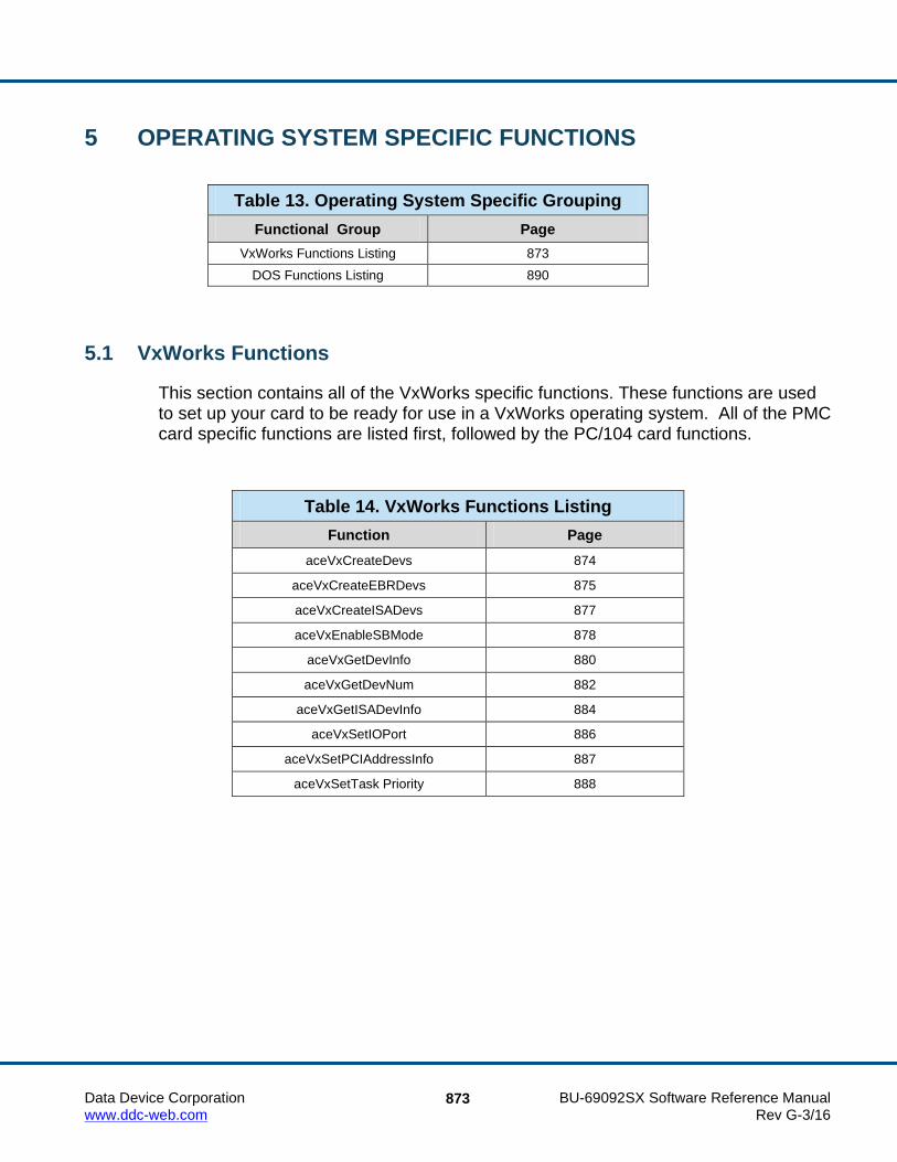
Data Device Corporation BU-69092SX Software Reference Manual www.ddc-web.com Rev G-3/16
873
5 OPERATING SYSTEM SPECIFIC FUNCTIONS
Table 13. Operating System Specific Grouping Functional Group Page
VxWorks Functions Listing 873 DOS Functions Listing 890
5.1 VxWorks Functions
This section contains all of the VxWorks specific functions. These functions are used to set up your card to be ready for use in a VxWorks operating system. All of the PMC card specific functions are listed first, followed by the PC/104 card functions.
Table 14. VxWorks Functions Listing
Function Page aceVxCreateDevs 874
aceVxCreateEBRDevs 875
aceVxCreateISADevs 877
aceVxEnableSBMode 878
aceVxGetDevInfo 880
aceVxGetDevNum 882
aceVxGetISADevInfo 884
aceVxSetIOPort 886
aceVxSetPCIAddressInfo 887
aceVxSetTask Priority 888

V X W O R K S F U N C T I O N D E F I N I T I O N S
Data Device Corporation BU-69092SX Software Reference Manual www.ddc-web.com Rev G-3/16
874
aceVxCreateDevs This function is used to setup PMC Cards located on a VME carrier card.
PROTOTYPE S16BIT _DECL aceVxCreateDevs(U32BIT dwCarrierBase, U16BIT wIrqLevel);
HARDWARE EMACE, E²MA, AceXtreme
STATE Initialization
MODE N/A
PARAMETERS dwCarrierBase (input parameter)
An unsigned 32-bit word value that specifies the base address of the VME carrier card that the 1553 hardware is plugged onto. This address would normally be set on the card by adjusting jumpers or switches on the VME carrier card.
wIrqLevel (input parameter)
An unsigned 16-bit word value that specifies the interrupt vector that should be used by the device driver for all DDC 1553 devices that are installed on the VME card. Adjusting jumpers on the card to the desired interrupt vector value would normally set this address.
DESCRIPTION This function is used to create accessible VxWorks device names (one per channel on a card) for all PMC Cards (BU-65565) located on a VME carrier card. The carrier is specified by its base address input by the user in the dwCarrierBase input parameter. This parameter should be zero if enumerating the local PCI bus. This function may be called once for each VME carrier card in the system and once for the local PCI bus.
RETURN VALUE S16BIT nResult The number of devices that have been created ACE_ERR_TOO_MANY_DEVS There are more than 32 devices defined ACE_ERR_INVALID_OS This is an invalid operating system and/or the device is not
a PMC card
EXAMPLE None
SEE ALSO None

V X W O R K S F U N C T I O N D E F I N I T I O N S
Data Device Corporation BU-69092SX Software Reference Manual www.ddc-web.com Rev G-3/16
875
aceVxCreateEBRDevs This function is used to setup the Enhanced Bit Rate 1553 PC/104 Cards located on the ISA bus.
PROTOTYPE S16BIT _DECL aceVxCreateEBRDevs (U32BIT dwMemBaseAddr, U16BIT wIrqLevel, U32BIT dwRegBaseAddr);
HARDWARE EMACE, E²MA, AceXtreme
STATE Initialization
MODE N/A
PARAMETERS dwMemBaseAddr (input parameter)
An unsigned 32-bit word value that specifies the base address of the VME carrier card that the device is plugged onto. This address would normally be set on the card by adjusting jumpers or switches on the VME carrier card.
wIrqLevel (input parameter)
An unsigned 16-bit word value that specifies the interrupt vector that should be used by the device driver for all DDC 1553 cards that are installed on the VME card. Adjusting jumpers on the card to the desired interrupt vector value would normally set this address.
dwRegBaseAddr (input parameter)
An unsigned 32-bit word value that specifies the base register address.
DESCRIPTION This function is used to setup the Enhanced Bit Rate 1553 PC/104 Cards located on the ISA bus. This function is only applicable to the Enhanced Bit Rate PC/104 card.
RETURN VALUE S16BIT nResult The number of devices that have been created ACE_ERR_MAPMEM_ACC The card did not map to memory properly ACE_ERR_INVALID_OS This is an invalid operating system and/or the
device is not a PC/104 card
V X W O R K S F U N C T I O N D E F I N I T I O N S
Data Device Corporation BU-69092SX Software Reference Manual www.ddc-web.com Rev G-3/16
876
aceVxCreateEBRDevs (continued) EXAMPLE
None
SEE ALSO None

V X W O R K S F U N C T I O N D E F I N I T I O N S
Data Device Corporation BU-69092SX Software Reference Manual www.ddc-web.com Rev G-3/16
877
aceVxCreateISADevs This function is used to setup the PC/104 cards located on the ISA bus.
PROTOTYPE S16BIT _DECL aceVxCreateISADevs(U32BIT dwMemBaseAddr, U16BIT wIrqLevel, U32BIT dwRegBaseAddr);
HARDWARE EMACE, E²MA, AceXtreme
STATE Initialization
MODE N/A
PARAMETERS dwMemBaseAddr (input parameter)
An unsigned 32-bit word value that specifies the base memory address. wIrqLevel (input parameter)
An unsigned 16-bit word value that specifies the interrupt vector that should be used by the device driver for all DDC 1553 cards that are installed on the ISA bus.
dwRegBaseAddr (input parameter)
An unsigned 32-bit word value that specifies the register base memory address.
DESCRIPTION This function is used to setup the PC/104 Cards located on the ISA Bus. The function configures the I/O registers and sets up the base memory address input by the user and the base register address input by the user.
RETURN VALUE S16BIT nResult The number of devices that have been created ACE_ERR_INVALID_OS This is an invalid operating system and/or the device is not a
PC/104 card
EXAMPLE None
SEE ALSO None

V X W O R K S F U N C T I O N D E F I N I T I O N S
Data Device Corporation BU-69092SX Software Reference Manual www.ddc-web.com Rev G-3/16
878
aceVxEnableSBMode This function allows the user to enable / disable the South Bridge mode feature of BU-65568 and BU-6558x PC/104 cards .
PROTOTYPE S16BIT _DECL aceVxEnableSBMode (U16BIT wCardType, U16BIT bEnable);
HARDWARE EMACE, E²MA, AceXtreme
STATE Initialization
MODE N/A
PARAMETERS wCardType (input parameter) Card Type Selection Valid values: 0 for BU-65568, 1 for BU-6558x bEnable (input parameter) Switch to enable / disable South Bridge Mode Valid values: FALSE This will disable interrupts TRUE This will enable interrupts
DESCRIPTION This will enable / disable the South Bridge feature of the BU-65568 and BU-6558x PC/104 devices. This feature, when enabled, turns on an enhanced address decoder built into later generation DDC PC/104 cards. The enhancements include:
• Support for address decoding of 128K memory space allowing for 16-bit and 8-bit memory devices to be located within the same 128K paragraph of system memory.
• Enhancement to decoding of Latched Address (LA) bus that provides for increased
reliability of address decoding.
This feature takes advantage of systems that have both the SA and LA address bus signals at the same time (i.e. systems that have the ISA address bus are based on a South Bridge PCI interface).

V X W O R K S F U N C T I O N D E F I N I T I O N S
Data Device Corporation BU-69092SX Software Reference Manual www.ddc-web.com Rev G-3/16
879
aceVxEnableSBMode (continued) RETURN VALUE
ACE_ERR_SUCCESS The function completed successfully
EXAMPLE //Enable South Bridge Mode for a BU-65568 assigned as device #0 aceVxEnableSBMode (0, TRUE);
SEE ALSO None

V X W O R K S F U N C T I O N D E F I N I T I O N S
Data Device Corporation BU-69092SX Software Reference Manual www.ddc-web.com Rev G-3/16
880
aceVxGetDevInfo This function is used to retrieve physical information associated with a mapped logical device number.
PROTOTYPE S16BIT _DECL aceVxGetDevInfo(S16BIT DevNum, U32BIT *pCarrierBase, S32BIT *pBusNo, S32BIT *pDevNo, S32BIT *pFuncNo, U16BIT *pChannel);
HARDWARE EMACE, E²MA, AceXtreme
STATE Initialization
MODE N/A
PARAMETERS DevNum (input parameter)
A signed 16-bit word value that specifies which device the requested information pertains to. This device number may have been received from a previous call to aceVxGetDevNum() and is based on the location in the computer.
pCarrierBase (output parameter)
A pointer to an unsigned 32-bit word that will contain the base address of the VME carrier card that the specified device is plugged into. This address would normally be set on the card by adjusting jumpers or switches on the VME card.
pBusNo (output parameter)
A pointer to a signed 32-bit word that will contain the number of the PCI bus where the specified device resides.
pDevNo (output parameter) A pointer to a signed 32-bit word that will contain the PCI Device (or slot)
number where the card resides.

V X W O R K S F U N C T I O N D E F I N I T I O N S
Data Device Corporation BU-69092SX Software Reference Manual www.ddc-web.com Rev G-3/16
881
aceVxGetDevInfo (continued) pFuncNo (output parameter) A pointer to a signed 32-bit word that will return the PCI function number. Valid values: 0 BU-65565 PMC card Other values are reserved for future use. pChannel (input parameter)
A pointer to a signed 32-bit word that will contain the channel number of the device on the card.
DESCRIPTION This function is used to retrieve physical information associated with a mapped logical device number. The channel is fully specified by its address (0 if on local PCI bus), PCI Bus number, PCI Device number, PCI function number, the channel on the card and the channel number on the card.
RETURN VALUE S16BIT nResult 0 if device is found -1 if device is not found ACE_ERR_INVALID_OS This is not VxWorks and/or this is not a PMC card
EXAMPLE None
SEE ALSO None

V X W O R K S F U N C T I O N D E F I N I T I O N S
Data Device Corporation BU-69092SX Software Reference Manual www.ddc-web.com Rev G-3/16
882
aceVxGetDevNum This function is used to retrieve a logical device number associated with a particular channel on the PMC card.
PROTOTYPE S16BIT _DECL aceVxGetDevNum(S16BIT *pDevNum, U32BIT dwCarrierBaseAddr, S32BIT nBusNo, S32BIT nDevNo, S32BIT nFuncNo, U16BIT wChannel)
HARDWARE EMACE, E²MA, AceXtreme
STATE Initialization
MODE N/A
PARAMETERS pDevNum (output parameter) A signed 16-bit word pointer to a signed short variable that will be
filled with the device number by function. This device number will be used when accessing all functions for the SDK.
dwCarrierBaseAddr (input parameter) An unsigned 32-bit word value that specifies the base memory
address of the VME carrier card on which the DDC 1553 card is plugged into. This address would normally be set on the card by adjusting jumpers or switches on the VME card. This parameter should be set to 0 if the DDC card is located on the processor card in order to specify the local PCI bus.
nBusNo (input parameter) Specify the number of the PCI bus where DDC card resides. nDevNo (input parameter) Specify the PCI Device (or slot) number where card resides.

V X W O R K S F U N C T I O N D E F I N I T I O N S
Data Device Corporation BU-69092SX Software Reference Manual www.ddc-web.com Rev G-3/16
883
aceVxGetDevNum (continued) nFuncNo (input parameter) Specify the PCI function number. Valid values: 0 Use this value for the BU-65565 PMC card Other values reserved for future use wChannel (input parameter) Specify the channel number on the card. If the card contains more
than one 1553 channel, this parameter will specify which one is being accessed.
Valid values: 0 First installed channel 1 Second installed channel >1 and < maximum channels on card Other installed channels
DESCRIPTION This function is used to retrieve a logical device number associated with a particular channel. The channel is fully specified by its address (0 if on local PCI bus), PCI Bus number, PCI Device number, PCI function number, the channel on the card and the channel number on the card. This function can not be used with the PC/104 card.
RETURN VALUE S16BIT nResult 0 if device is found -1 if device is not found ACE_ERR_INVALID_OS This is not VxWorks and/or this is not a PMC card
EXAMPLE None
SEE ALSO None

V X W O R K S F U N C T I O N D E F I N I T I O N S
Data Device Corporation BU-69092SX Software Reference Manual www.ddc-web.com Rev G-3/16
884
aceVxGetISADevInfo This function is used to retrieve physical information associated with a mapped logical device number for a PC/104 card.
PROTOTYPE S16BIT _DECL aceVxGetISADevInfo (U16BIT DevNum, U16BIT *pChannel, U32BIT *pBaseMem, U32BIT *pBaseReg);
HARDWARE EMACE, E²MA, AceXtreme
STATE Initialization
MODE N/A
PARAMETERS DevNum (input parameter)
An unsigned 16-bit word value that specifies which device the requested information pertains to.
pChannel (output parameter)
A pointer to an unsigned 16-bit word that will contain the channel number of the device on the card.
pBaseMem (output parameter)
A pointer to an unsigned 32-bit word that will contain the base memory address of the card.
pBaseReg (output parameter)
A pointer to an unsigned 32-bit word that will contain the base register address of the card.
DESCRIPTION This function is used to retrieve physical information associated with a mapped logical device number.
RETURN VALUE S16BIT nResult -1: Error ACE_ERR_SUCCESS The function completed successfully ACE_ERR_INVALID_OS This is an invalid operating system and/or the device is not a
PC/104 card

V X W O R K S F U N C T I O N D E F I N I T I O N S
Data Device Corporation BU-69092SX Software Reference Manual www.ddc-web.com Rev G-3/16
885
aceVxGetISADevInfo (continued) EXAMPLE
None
SEE ALSO None

V X W O R K S F U N C T I O N D E F I N I T I O N S
Data Device Corporation BU-69092SX Software Reference Manual www.ddc-web.com Rev G-3/16
886
aceVxSetIOPort This function allows the user to set the base I/O address of the PC/104 card.
PROTOTYPE VOID _DECL aceVxSetIOPort (U16BIT wPort);
HARDWARE EMACE, E²MA, AceXtreme
STATE Initialization
MODE N/A
PARAMETERS wPort (input parameter) The user specified port number.
DESCRIPTION This function allows the user to set the base I/O address of the card. The default I/O base address is 0x360.
Note: This function is effective only if the aceVxCreateISADevs() function has not been called since the target hardware has been powered up.
RETURN VALUE None
EXAMPLE None
SEE ALSO None

V X W O R K S F U N C T I O N D E F I N I T I O N S
Data Device Corporation BU-69092SX Software Reference Manual www.ddc-web.com Rev G-3/16
887
aceVxSetPCIAddressInfo This function allows the user to specify where a PMC card residing on the local bus will be placed in memory.
PROTOTYPE S16BIT _DECL aceVxSetPCIAddressInfo(U32BIT dwPCIBaseAddress, U32BIT dwPCIWindowSize);
HARDWARE EMACE, E²MA, AceXtreme
STATE Initialization
MODE N/A
PARAMETERS dwPCIBaseAddress (input parameter) An unsigned 32-bit word value that specifies the start location into
which cards memory can be configured. dwPCIWindowSize (input parameter) An unsigned 32-bit word value that specifies the total size of the
memory window where cards will reside.
DESCRIPTION This function allows the user to specify where a PMC card residing on the local bus will be placed in memory. The user can specify the base address and size of memory window that the PMC card(s) are allowed to map to. Example: The default base address is 0xFD000000, with a size of 0x01000000 (16MB).
Note: Since all PMC cards that reside on the local PCI bus will be configured with one call to aceVxCreateDevs(), this function need only be called once before the call to aceVxCreateDevs(),
RETURN VALUE ACE_ERR_SUCCESS The function completed successfully ACE_ERR_INVALID_OS This is not VxWorks and/or this is not a PMC card
EXAMPLE None
SEE ALSO None

V X W O R K S F U N C T I O N D E F I N I T I O N S
Data Device Corporation BU-69092SX Software Reference Manual www.ddc-web.com Rev G-3/16
888
aceVxSetTaskPriority This function allows the user to change the priority of the DPC ISR task thread.
PROTOTYPE S16BIT _DECL aceVxSetTaskPriority (S16BIT DevNum, int nPriority);
HARDWARE EMACE, E²MA, AceXtreme
STATE N/A
MODE N/A
PARAMETERS DevNum (input parameter) A signed 16-bit word value that specifies the device. nPriority (input parameter) An integer value that specifies the interrupt priority in the system. Valid Values: 0 to 255
DESCRIPTION When a hardware interrupt fires, the device driver Hardware Interrupt Procedure is called (e.g. vxHwIntProc). The Hardware Interrupt Procedure is responsible for clearing any hardware interrupts generated by the applicable DDC hardware product. Once the hardware interrupt is cleared, a DPC (Deferred Process Call) is made to the previously spawned Interrupt Service Routine (ISR). The ISR is responsible for servicing any SDK internal processes as well as any assigned external ISR assigned by the user. The aceVxSetTaskPriority() function allows the user to set the priority of the DPC task.
RETURN VALUE ACE_ERR_SUCCESS The function completed successfully ACE_ERR_INVALID_DEVNUM The device number input by the user is invalid ACE_ERR_PARAMETER The priority input is invalid or the ISR does not exist ACE_ERR_TASK_FAIL The priority failed to be set properly

V X W O R K S F U N C T I O N D E F I N I T I O N S
Data Device Corporation BU-69092SX Software Reference Manual www.ddc-web.com Rev G-3/16
889
aceVxSetTaskPriority (continued) EXAMPLE
//set device 0’s DPC task thread priority to 100 nResult = aceVxSetTaskPriority(DevNum, 100);
SEE ALSO None

Data Device Corporation BU-69092SX Software Reference Manual www.ddc-web.com Rev G-3/16
890
5.2 DOS Functions
This section contains all of the DOS specific functions. These functions are used to set up your card to be ready for use in a DOS operating system.
Table 15. DOS Functions Listing
Function Page aceDOSCreateDevice 891
aceDOSEnableSBMode 892

D O S F U N C T I O N D E F I N I T I O N S
Data Device Corporation BU-69092SX Software Reference Manual www.ddc-web.com Rev G-3/16
891
aceDOSCreateDevice This function configures the device for use in a DOS operating system.
PROTOTYPE S16BIT _DECL aceDOSCreateDevice (char *pFileName);
HARDWARE EMACE, E²MA, AceXtreme
STATE Initialization
MODE N/A
PARAMETERS pFileName (input parameter) A pointer to a configuration file that contains the card information.
DESCRIPTION This function configures the device for use in a DOS operating system. The function maps the card’s memory into the system, and gives driver access to the card to start initializing its structure.
RETURN VALUE S16BIT nResult 0 An error occurred >0 The number of devices that have been created ACE_ERR_INVALID_OS This is not a DOS operating system
EXAMPLE None
SEE ALSO None

D O S F U N C T I O N D E F I N I T I O N S
Data Device Corporation BU-69092SX Software Reference Manual www.ddc-web.com Rev G-3/16
892
aceDOSEnableSBMode This function allows the user to enable / disable the South Bridge mode feature of BU-65568 and BU-6558x PC/104 cards.
PROTOTYPE S16BIT _DECL aceDOSEnableSBMode (U16BIT wCardType, U16BIT bEnable);
HARDWARE EMACE, E²MA, AceXtreme
STATE Initialization
MODE N/A
PARAMETERS wCardType (input parameter) Card Type Selection Valid values: 0 for BU-65568, 1 for BU-6558x bEnable (input parameter) Switch to enable / disable South Bridge Mode Valid values: FALSE This will disable interrupts TRUE This will enable interrupts
DESCRIPTION This will enable / disable the South Bridge feature of the BU-65568 and BU-6558x PC/104 devices. This feature, when enabled, turns on an enhanced address decoder built into later generation DDC PC/104 cards. The enhancements include:
Support for address decoding of 128K memory space allowing for 16-bit and 8-bit memory devices to be located within the same 128K paragraph of system memory.
Enhancement to decoding of Latched Address (LA) bus that provides for increased reliability of address decoding.
This feature takes advantage of systems that have both the SA and LA address bus signals at the same time (i.e. systems that have the ISA address bus are based on a South Bridge PCI interface).

D O S F U N C T I O N D E F I N I T I O N S
Data Device Corporation BU-69092SX Software Reference Manual www.ddc-web.com Rev G-3/16
893
aceDOSEnableSBMode (continued) RETURN VALUE
ACE_ERR_SUCCESS The function completed successfully
EXAMPLE //Enable South Bridge Mode for a BU-65568 assigned as device #0 aceDOSEnableSBMode (0, TRUE);
SEE ALSO None

Data Device Corporation BU-69092SX Software Reference Manual www.ddc-web.com Rev G-3/16
894
6 STRUCTURES Table 16. Structures Listing
Function Page ACE_IRIG_TX, PACE_IRIG_TX 896
ACEX_DEVICE_INFO 897
ACEX_DISC_CONFIG 899
ACEX_ERR_INJ 900
ACEX_MTI_METRICS 902
ACEX_TRG_CONFIG 903
ACEX_TRG_CONFIG_GPT 904
ACEX_TRG_CONFIG_TMT 906
ALISTNODE 908
BCOPERATION 909
BGGPQSTRUCT 910
CBUFINFO 911
CBUFTYPE 912
CHANCOUNT 913
DATABLOCKITEM 914
DBLKINFO 915
DBLKTYPE 916
DEVICEINFO 917
DLISTNODE 920
FRAMEITEM 921
FLISTNODE 922
GPQ 923
GPQENTRY 924
GPQMETRIC 925
HBUFMETRIC 926
HOSTBUFFER 927
HWVERSIONINFO, PHWVERSIONINFO 928
ISQENTRY 929
MEMOBJECTITEM 930
MEMORYBLOCK 931
MEMWORDITEM 932
MESSAGEITEM 933

S T R U C T U R E S
Data Device Corporation BU-69092SX Software Reference Manual www.ddc-web.com Rev G-3/16
895
Table 16. Structures Listing
Function Page MSGSTRUCT 934
MTI_CH10_DATA_PKT, PMTI_CH10_DATA_PKT 935
MTI_CH10_FILE_HANDLE 936
MTI_CH10_TIME_PKT PMTI_CH10_TIME_PKT 937
MTI_CONFIG, PMTI_CONFIG 938
MTINFO 939
MTOPERATION 940
MTSTACK 941
MTTRIGGER 942
OPCODEITEM 943
OPCODESTRUCT 944
REGSTATE 945
RTOPERATION 946
RTSTACK 947
SKMETRIC 948
STREAMITEM 949
SWVERSIONINFO, PSWVERSIONINFO 950

S T R U C T U R E S
Data Device Corporation BU-69092SX Software Reference Manual www.ddc-web.com Rev G-3/16
896
ACE_IRIG_TX, PACE_IRIG_TX DESCRIPTION
This structure contains information about the configuration of the IRIG B Transmitter registers.
INCLUDE #include “config.h”
DEFINITION typedef struct _ACE_IRIG_TX { U16BIT u16IRIGBTxSupported; U16BIT u16Enable; U16BIT u16Seconds; U16BIT u16Minutes; U16BIT u16Hours; U16BIT u16Days; U16BIT u16Year; U32BIT u32Control; } ACE_IRIG_TX, *PACE_IRIG_TX;

S T R U C T U R E S
Data Device Corporation BU-69092SX Software Reference Manual www.ddc-web.com Rev G-3/16
897
ACEX_DEVICE_INFO DESCRIPTION
This structure describes a device's state inside of the RTL. Note that there are several operating system-specific fields in this structure.
INCLUDE #include “axstruct.h”
DEFINITION typedef struct ACEX_DEVICE_INFO { WIN32INFO *pWin32; /*ptr to hold Win32 information */ wchar_t DevPath[128]; S8 szDeviceID[ACEX_DEVICE_ID_STRING_SIZE]; HANDLE hDevice; HANDLE hDeviceIrq; U32 u32CardType; U16 u16ApiType; U16 u16State; U16 u16MetricEna; U16 u16Access; U16 u16Channel; U16 u16Mode; U32 u32SubRTMask; U32 u32Slot; U32 u32Socket; U32 u32MemLength; U32 u32MemBA; U16 u16ModeOptions; U16 u32TTResolution; BOOLEAN bDeviceInitilized; U16 u16ISQEnabled; U16 u16SWMPrimeCheck; U32 u32MiscInfo; /*used for compatibility SRT Mode*/ U32 u32RtOptions; U32 u32RtCmdStkSize; U16 bLegacy; U16 (_DECL *funcInternalIsr)(S16BIT DevNum, U32BIT dwIrqStatus); void (_DECL *funcExternalIsr)(S16BIT DevNum, U32BIT dwIrqStatus); ACEX_1553_COMPONENT s1553; ACEX_API_FUNCTIONS sApi;

S T R U C T U R E S
Data Device Corporation BU-69092SX Software Reference Manual www.ddc-web.com Rev G-3/16
898
ACEX_DEVICE_INFO (continued)
RTOPERATION *pRT; MTOPERATION *pMT; U16 b1553a; CRITICAL_SECTION critPage; } ACEX_DEVICE_INFO;

S T R U C T U R E S
Data Device Corporation BU-69092SX Software Reference Manual www.ddc-web.com Rev G-3/16
899
ACEX_DISC_CONFIG DESCRIPTION
This structure contains the discrete configuration information for the triggers and intermessage routines.
INCLUDE #include “diox.h”
DEFINITION typedef struct _ACEX_DISC_CONFIG { U16BIT u16Polarity; U16BIT u16Control; U16BIT u16SelTrgImr; BOOLEAN bSSFDisable; }ACEX_DISC_CONFIG;
Table 17. ACEX_DISC_CONFIG Struct Member Description u16Polarity ACEX_DISC_ACTIVE_HI – The Discrete I/O transitions from logic 0 to logic 1 when active.
ACEX_DISC_ACTIVE_LO – The Discrete I/O transitions from logic 1 to logic 0 when active.
u16Control ACEX_DISC_SW_CTRL – The Discrete I/O is not driven by hardware. Software can drive them with the Discrete I/O API functions. ACEX_DISC_TRGIMR_CTRL – The Discrete I/O is driven by the output state of the Trigger or Intermessage Routine, depending on the value of “u16SelTrgImr”.
u16SelTrgImr ACEX_DISC_SEL_TRG – The Discrete I/O is linked to a Trigger. ACEX_DISC_SEL_IMR – The Discrete I/O is linked to an Intermessage Routine.
bSSFDisable Discrete I/O pins can also drive the Subsystem Flag (SSF) in a 1553 channel. 0 – Allow the Discrete I/O to drive the Subsystem Flag. 1 – Do not allow the Discrete I/O to drive the Subsystem Flag.

S T R U C T U R E S
Data Device Corporation BU-69092SX Software Reference Manual www.ddc-web.com Rev G-3/16
900
ACEX_ERR_INJ DESCRIPTION
This structure contains all information associated error injection.
INCLUDE #include “errorinj.h”
DEFINITION typedef struct _ACEX_ERR_INJ { U32BIT u32ErrorType; /* Injected Error type */ S16BIT s16WordSel; /* Specifies word with errors */ S16BIT s16WordCount; /* Word count error: -32 to -1, 0, 1, 2 to 32 words*/ S16BIT s16BitCount; /* Bit count error: -3, -2, -1, 0, 1, 2, 3 bits */ S16BIT s16GapTime; /* Gap error: 0 – 32 µseconds */ S16BIT s16GlitchLoc; /* Glitch error location: 0–400 in 50 ns steps (0–20µs) */ S16BIT s16GlitchDur; /* Glitch error duration 0–60 in 50 ns steps (0–3µs) */ S16BIT s16InverseLoc; /* Inverse error location: 0–400 in 50 ns steps (0–20µs) */ S16BIT s16InverseDur; /* Inverse error duration */ 0–60 in 50 ns steps (0–3µs) */ S16BIT s16RespLateTime; /* RT response late time 7–60 in 50 ns steps (3.5–30µs) */ S16BIT s16RespWrongAddr; /* Respond with wrong RT address */ U16BIT u16StatusBitMask; /* RT status bit mask */ U16BIT u16StatusBits; /* RT status bit modification */ } ACEX_ERR_INJ;

S T R U C T U R E S
Data Device Corporation BU-69092SX Software Reference Manual www.ddc-web.com Rev G-3/16
901
ACEX_ERR_INJ (continued)
u32ErrorTypes valid values General Error Types
ACEX_EI_NONE No Error
ACEX_EI_WORD_COUNT Word Count error (add/remove words)
ACEX_EI_BIT_COUNT Bit Count error (add/remove bits)
ACEX_EI_GLITCH Encoder output is idle on bus
ACEX_EI_INVERSE Encoder output is inverted
ACEX_EI_GAP Delay between words on bus
RT Specific Error Types ACEX_EI_NO_RESP_A RT will not respond to commands on Bus A
ACEX_EI_NO_RESP_B RT will not respond to commands on Bus B
ACEX_EI_RESP_LATE RT responds to commands late
ACEX_EI_RESP_WRONG_BUS RT responds to the command on opposite bus
ACEX_EI_RESP_WRONG_ADDR RT responds with different RT address in status word.

S T R U C T U R E S
Data Device Corporation BU-69092SX Software Reference Manual www.ddc-web.com Rev G-3/16
902
ACEX_MTI_METRICS DESCRIPTION
This structure describes MT-I metrics.
INCLUDE #include “configx.h”
DEFINITION typedef struct _ACEX_MTI_METRICS { U32 u32MtiStkPercentFull; U32 u32MtiStkPercentHigh; U32 u32MtiStkOverflowCount; U32 u32MtiDroppedMsgs; } ACEX_MTI_METRICS;

S T R U C T U R E S
Data Device Corporation BU-69092SX Software Reference Manual www.ddc-web.com Rev G-3/16
903
ACEX_TRG_CONFIG DESCRIPTION
This structure contains the trigger configuration information including a union of the TMT and GPT data structures.
INCLUDE #include “trgx.h”
DEFINITION typedef struct _ACEX_TRG_CONFIG { union ACEX_TRG_CONFIG_UNION { ACEX_TRG_CONFIG_TMT sTmt; /* Time Message trigger configuration */ ACEX_TRG_CONFIG_GPT sGpt; /* General Purpose trigger configuration */ }u; } ACEX_TRG_CONFIG;

S T R U C T U R E S
Data Device Corporation BU-69092SX Software Reference Manual www.ddc-web.com Rev G-3/16
904
ACEX_TRG_CONFIG_GPT DESCRIPTION
This structure contains the trigger configuration information for the General Purpose triggers.
INCLUDE #include “trgx.h”
DEFINITION typedef struct _ACEX_TRG_CONFIG_GPT {
U8BIT u8InGptTrg; BOOLEAN bSet; BOOLEAN bClrNotMatched; BOOLEAN bClrAuto; BOOLEAN bClrNewMsg; BOOLEAN bBcCmdEn; BOOLEAN bBcDataEn; BOOLEAN bRtStatusEn; BOOLEAN bRtDataEn; BOOLEAN bBswEn; BOOLEAN bBusAEn; BOOLEAN bBusBEn; U8BIT u8DataCnt; U8BIT u8TrgCnt; U16BIT u16Mask; U16BIT u16Data;
} ACEX_TRG_CONFIG_GPT;
Table 18. ACEX_TRG_CONFIG_GPT Struct Member Description u8InGptTrg Controls which input will arm the trigger.
ACEX_TRG_IN_DISABLE – Trigger will not arm. ACEX_TRG_IN_START – Trigger will be armed immediately by software when the trigger is enabled. ACEX_TRG_IN_DISC –The GPTn will be armed by its respective Discrete I/O pin (DIO_n) transitioning from logic 0 to logic 1, where n = 1, 2, …. ACEX_TRG_IN_TMT1, ACEX_TRG_IN_TMT2 – Trigger will be armed by the specified Time Message Trigger’s output. ACEX_TRG_IN_GPT1, ACEX_TRG_IN_GPT2, …, ACEX_TRG_IN_GPT16 – Trigger will be armed by the specified General Purpose Trigger’s output.

S T R U C T U R E S
Data Device Corporation BU-69092SX Software Reference Manual www.ddc-web.com Rev G-3/16
905
Table 18. ACEX_TRG_CONFIG_GPT Struct Member Description bSet Software can manually fire the trigger, used for testing.
0 – Do not fire. Trigger will operate as programmed. 1 – Fire the trigger immediately.
bClrNotMatched 1 – Clear the trigger output when the trigger pattern matching fails on the message.
bClrAuto Determines the clearing of the trigger output after firing. 0 – Do not auto-clear. Software must clear it manually. 1 – Auto-clear after 1 DDC hardware clock cycle.
bClrNewMsg 1 – Automatically clear the trigger output on the next new message received by the MT.
bBcCmdEn 1 – Trigger will fire when the MT’s BC Command Word matches the Data Word matching criterion given by “u16Mask” and “u16Data”.
bBcDataEn 1 – Trigger will fire when the MT’s BC Data Word matches the Data Word matching criterion given by “u16Mask” and “u16Data”.
bRtStatusEn 1 – Trigger will fire when the MT’s RT Status Word matches the Data Word matching criterion given by “u16Mask” and “u16Data”.
bRtDataEn 1 – Trigger will fire when the MT’s RT Data Word matches the Data Word matching criterion given by “u16Mask” and “u16Data”.
bBswEn 1 – Trigger will fire when the MT’s Block Status Word matches the Data Word matching criterion given by “u16Mask” and “u16Data”.
bBusAEn 1 – Trigger will fire when the trigger pattern match occurs on Bus A.
bBusBEn 1 – Trigger will fire when the trigger pattern match occurs on Bus B.
u8DataCnt This specifies which data word in a message to perform the trigger pattern matching. Valid data word positions are 1 to 32. A value of 0 will match all data words in a message.
u8TrgCnt The number of times the trigger pattern match must be met before firing.
u16Mask Specifies the mask value for the Data Word matching criterion. Only bits set to ‘1’ will cause target word to be matched with the “u16Data”.
u16Data Specifies the data pattern for the Data Word matching criterion.

S T R U C T U R E S
Data Device Corporation BU-69092SX Software Reference Manual www.ddc-web.com Rev G-3/16
906
ACEX_TRG_CONFIG_TMT DESCRIPTION
This structure contains the trigger configuration information for the time-message triggers.
INCLUDE #include “trgx.h”
DEFINITION typedef struct _ACEX_TRG_CONFIG_TMT { U8BIT u8InTmtTrg; BOOLEAN bSet;
BOOLEAN bTimeTrg; BOOLEAN bInUs; BOOLEAN bClrAuto; U16BIT u16TMTCount;
} ACEX_TRG_CONFIG_TMT;
Table 19. ACEX_TRG_CONFIG_TMT Struct Member Description u8InTmtTrg Controls which input will arm the trigger.
ACEX_TRG_IN_DISABLE – Trigger will not arm. ACEX_TRG_IN_START – Trigger will be armed immediately by software when the trigger is enabled. ACEX_TRG_IN_TMT1, ACEX_TRG_IN_TMT2 – Trigger will be armed by the specified Time Message Trigger’s output. ACEX_TRG_IN_GPT1, ACEX_TRG_IN_GPT2, …, ACEX_TRG_IN_GPT16 – Trigger will be armed by the specified General Purpose Trigger’s output.
bSet Software can manually fire the trigger, used for testing. 0 – Do not fire. Trigger will operate as programmed. 1 – Fire the trigger immediately.
bTimeTrg 0 – Message counting mode. The MT must be running. 1 – Time triggered mode.
bInUs Determines the resolution and unit of “u16TMTCount” in time triggered mode. 0 – 1 millisecond (ms) per bit. 1 – 1 microsecond (µs) per bit.
bClrAuto Determines the clearing of the trigger output after firing. 0 – Do not auto-clear. Software must clear it manually. 1 – Auto-clear after 1 DDC hardware clock cycle.

S T R U C T U R E S
Data Device Corporation BU-69092SX Software Reference Manual www.ddc-web.com Rev G-3/16
907
Table 19. ACEX_TRG_CONFIG_TMT Struct Member Description u16TMTCount In time triggered mode, this is the wait time (with the resolution specified in “bInUs”) before
the trigger fires. In message count mode, this is number of messages the MT will count before the trigger fires..

S T R U C T U R E S
Data Device Corporation BU-69092SX Software Reference Manual www.ddc-web.com Rev G-3/16
908
ALISTNODE DESCRIPTION
This structure contains information associated with a node for a double linked list for aysnchronous messages.
INCLUDE #include “structs.h”
DEFINITION typedef struct ALISTNODE { S16BIT nMsgID; /* Message ID */ S32BIT ndwMsgAddr; /* HW Address of Message */ S16BIT nOpID; /* OpCode Associated with Message */ U16BIT bSent; /* Did message succesfully get sent */ struct ALISTNODE *pPrev; /* Previous element in the list or NULL */ struct ALISTNODE *pNext; /* Next element in the list or NULL */ } ALISTNODE;

S T R U C T U R E S
Data Device Corporation BU-69092SX Software Reference Manual www.ddc-web.com Rev G-3/16
909
BCOPERATION DESCRIPTION
This structure describes the Bus Controller (BC) mode of operation.
INCLUDE #include “structs.h”
DEFINITION typedef struct BCOPERATION { S32BIT lMjrFrmCount; /* Number of major frames to run, -1 forever*/ U32BIT dwOptions; /* BC Operation options */ U16BIT wMjrFrmTime; /* The 'MAJOR' frame time (global) */ U16BIT wMjrFlags; /* The 'MAJOR' frame flags (global) */ U16BIT wWDTimeOut; /* Watchdog timer timeout */ U16BIT bRunForever; /* Is the BC to run forever? */ U32BIT dwAsyncFrmAddr; /* Async Frame Address */ U16BIT wAsyncCount; /* Counter of Asynch Messages */ GPQ sGPQ; /* General Purpose Queue */ BCGPQSTRUCT sGPQUser; /* buffered user GPQ */ BCGPQSTRUCT sGPQLib; /* buffered RTL GPQ */ HOSTBUFFER sHBuf; /* BC Operation Host Buffer */ DLISTNODE *pFrames; /* DLIST of frames */ DLISTNODE *pOpCodes; /* DLIST of opcodes */ DLISTNODE *pMsgBlks; /* DLIST of msg blocks */ DLISTNODE *pDataBlks; /* DLIST of data blocks */ DLISTNODE *pAsyncOp; /* DLIST of async opcodes */ ALISTNODE *pAsyncList; /* ALIST of async messages */ ALISTNODE *pAListTemp; /* Temp ALIST of async msgs */ FLISTNODE *pFrameList; /* FLIST of frames */ } BCOPERATION;

S T R U C T U R E S
Data Device Corporation BU-69092SX Software Reference Manual www.ddc-web.com Rev G-3/16
910
BCGPQSTRUCT DESCRIPTION
This structure describes a buffered General Purpose Queue (BGPQ) used by the Bus Controller (BC).
INCLUDE #include “structs.h”
DEFINITION typedef struct BCGPQSTRUCT { U16BIT wGPQHead; /* index to the next unread entry */ U16BIT wGPQTail; /* index to the next free location */ U16BIT aGPQ[BC_BUF_GPQ_SIZE]; /* the buffered queue */ } BCGPQSTRUCT;

S T R U C T U R E S
Data Device Corporation BU-69092SX Software Reference Manual www.ddc-web.com Rev G-3/16
911
CBUFINFO DESCRIPTION
This structure holds information about RT Circular Buffers.
INCLUDE #include “structs.h”
DEFINITION typedef struct CBUFINFO { U16BIT bEnabled; /* Is the circular buffer enabled */ U16BIT nCircBufID; /* ID of Circular Buffer */ U32BIT dwSize; /* Size of the circular buffer */ U32BIT dwStartAddr; /* Start address of the circular buffer */ } CBUFINFO;

S T R U C T U R E S
Data Device Corporation BU-69092SX Software Reference Manual www.ddc-web.com Rev G-3/16
912
CBUFTYPE DESCRIPTION
This structure holds information about the type of RT Circular Buffers.
INCLUDE #include “structs.h”
DEFINITION typedef struct CBUFTYPE { CBUFINFO Transmit; /* Transmit circular buffer info */ CBUFINFO Receive; /* Receive circular buffer info */ } CBUFTYPE;

S T R U C T U R E S
Data Device Corporation BU-69092SX Software Reference Manual www.ddc-web.com Rev G-3/16
913
CHANCOUNT DESCRIPTION
This structure contains the number of discrete and avionic I/O lines a card has.
INCLUDE #include “dio.h”
DEFINITION typedef struct _CHANCOUNT { U8BIT bTx; /* Number of Transmitters */ U8BIT bRx; /* Number of Receivers */ U8BIT bGroup; /* Number of Groups */ U8BIT bDiscrete; /* Number of Discrete Channels */ U8BIT bAvionic; /* Number of Avionic Channels */ U8BIT bRs232; /* Number of RS232 Channels */ U8BIT bRs485; /* Number of RS485 Channels */ U8BIT bBoardModel; /* Device specific model */ U8BIT b1553; /* Number of MIL-STD-1553 channels */ } CHANCOUNT_t, *CHANCOUNT_p;

S T R U C T U R E S
Data Device Corporation BU-69092SX Software Reference Manual www.ddc-web.com Rev G-3/16
914
DATABLOCKITEM DESCRIPTION
This structure contains information associated with a Data Block in memory.
INCLUDE #include “structs.h”
DEFINITION typedef struct DATABLOCKITEM { struct DLISTNODE*pMemNode; /* pointer to memory node */ U32BIT dwLastRW; /* the last read or written location */ U32BIT dwXQFAddr; /* Address of XQF opcode if double buffered */ U32BIT dwSATx; /* Each bit represents Tx DBlk mapping */ U32BIT dwSARx; /* Each bit represents Rx DBlk mapping */ U32BIT dwSABcst; /* Each bit represents Bcst DBlk mapping*/ U32BIT dwWordCount; /* Number Of 1553 Words In Data Block */ S8BIT s8RtAddr; /* RtAddress sf+ */ U32BIT u32UseCount; /* Use counter */ U16BIT u16Index; /* Data Block Index Number */ } DATABLOCKITEM;

S T R U C T U R E S
Data Device Corporation BU-69092SX Software Reference Manual www.ddc-web.com Rev G-3/16
915
DBLKINFO DESCRIPTION
This structure holds information about RT Data Block.
INCLUDE #include “structs.h”
DEFINITION typedef struct DLBKINFO { U16BIT bEnabled; /* Is the Data Block enabled */ U16BIT nDataBlkID; /* ID of Data Block */ U32BIT dwSize; /* Size of the data block */ U32BIT dwStartAddr; /* Start address of the data block */ } DBLKINFO;

S T R U C T U R E S
Data Device Corporation BU-69092SX Software Reference Manual www.ddc-web.com Rev G-3/16
916
DBLKTYPE DESCRIPTION
This structure holds information about the type of RT Data Blocks.
INCLUDE #include “structs.h”
DEFINITION typedef struct DBLKTYPE { DBLKINFO Transmit; /* Transmit data block info */ DBLKINFO Receive; /* Receive data block info */ } DBLKTYPE;
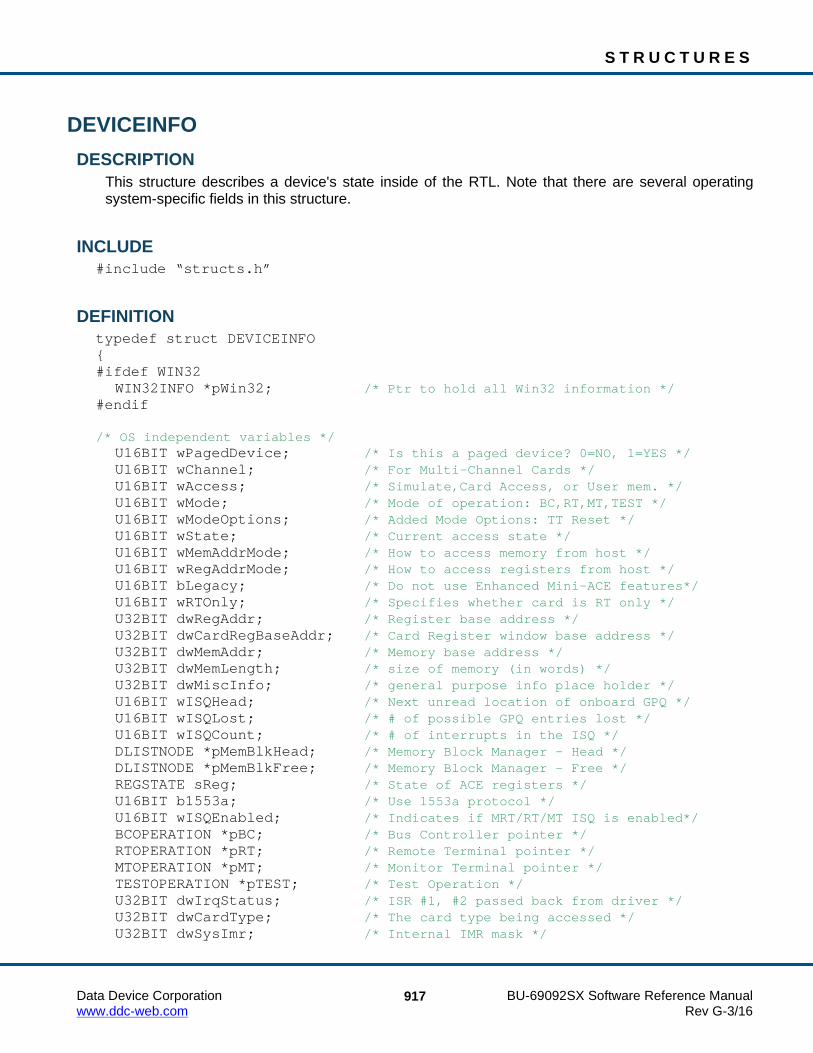
S T R U C T U R E S
Data Device Corporation BU-69092SX Software Reference Manual www.ddc-web.com Rev G-3/16
917
DEVICEINFO DESCRIPTION
This structure describes a device's state inside of the RTL. Note that there are several operating system-specific fields in this structure.
INCLUDE #include “structs.h”
DEFINITION typedef struct DEVICEINFO { #ifdef WIN32 WIN32INFO *pWin32; /* Ptr to hold all Win32 information */ #endif /* OS independent variables */ U16BIT wPagedDevice; /* Is this a paged device? 0=NO, 1=YES */ U16BIT wChannel; /* For Multi-Channel Cards */ U16BIT wAccess; /* Simulate,Card Access, or User mem. */ U16BIT wMode; /* Mode of operation: BC,RT,MT,TEST */ U16BIT wModeOptions; /* Added Mode Options: TT Reset */ U16BIT wState; /* Current access state */ U16BIT wMemAddrMode; /* How to access memory from host */ U16BIT wRegAddrMode; /* How to access registers from host */ U16BIT bLegacy; /* Do not use Enhanced Mini-ACE features*/ U16BIT wRTOnly; /* Specifies whether card is RT only */ U32BIT dwRegAddr; /* Register base address */ U32BIT dwCardRegBaseAddr; /* Card Register window base address */ U32BIT dwMemAddr; /* Memory base address */ U32BIT dwMemLength; /* size of memory (in words) */ U32BIT dwMiscInfo; /* general purpose info place holder */ U16BIT wISQHead; /* Next unread location of onboard GPQ */ U16BIT wISQLost; /* # of possible GPQ entries lost */ U16BIT wISQCount; /* # of interrupts in the ISQ */ DLISTNODE *pMemBlkHead; /* Memory Block Manager - Head */ DLISTNODE *pMemBlkFree; /* Memory Block Manager - Free */ REGSTATE sReg; /* State of ACE registers */ U16BIT b1553a; /* Use 1553a protocol */ U16BIT wISQEnabled; /* Indicates if MRT/RT/MT ISQ is enabled*/ BCOPERATION *pBC; /* Bus Controller pointer */ RTOPERATION *pRT; /* Remote Terminal pointer */ MTOPERATION *pMT; /* Monitor Terminal pointer */ TESTOPERATION *pTEST; /* Test Operation */ U32BIT dwIrqStatus; /* ISR #1, #2 passed back from driver */ U32BIT dwCardType; /* The card type being accessed */ U32BIT dwSysImr; /* Internal IMR mask */

S T R U C T U R E S
Data Device Corporation BU-69092SX Software Reference Manual www.ddc-web.com Rev G-3/16
918
DEVICEINFO (continued) U32BIT dwUsrImr; /* External IMR mask */ U16BIT bMetricEna; /* Are Performance metrics enabled */ U16BIT bSWMPrimeCheck; /* Is SW Check necessary of M' issues */ U16BIT wCanBusStatus; /* Can Bus Interrupt Status for EBR */ U16BIT wEbrMode; /* Ebr Channel */ U16BIT wNumOfChnls; /* Number of channels on the device */ U16BIT wHubNum; /* Hub Port for the EBR device */ /* Interrupt Handlers */ U16BIT(_DECL *funcInternalIsr)(S16BIT DevNum, U32BIT dwIrqStatus); void(_DECL *funcExternalIsr)(S16BIT DevNum, U32BIT dwIrqStatus); void(_DECL *funcCANIsr)(S16BIT DevNum, U16BIT wIrqStatus); void(_DECL *funcAsyncIsr)(S16BIT DevNum, U16BIT wMnrFrmId); /* Linux */ #ifdef LINUX int hDevice; /* Handle to unix device */ U32BIT dwInterruptQueHead; /* Head of interrupt pending queue */ U32BIT dwInterruptQueTail; /* Tail of interrupt pending queue */ U32BIT *adwIrqStatus; /* Array of interrupt status(s) for IQS */ pthread_t thDispatch; /* Interrupt thread (Dispatch) */ pthread_t thWorker; /* Interrupt thread (Worker) */ U16BIT wThParam; /* Parameter for new threads */ pthread_cond_t thcQue; /* Interrupt que condition object */ pthread_mutex_t thmQue; /* Interrupt que mutex */ U8BIT bCard; /* Card number for semaphores */ #endif /* VxWorks & DOS */ #if ((defined(VX_WORKS) && defined(PC_104)) || defined(DOS)) U16BIT wPaged; /* Is the memory paged or not */ U16BIT wCurPage; /* Current Page we are on */ U16BIT wCurChnl; /* Current Channel we are on */ U16BIT wIrqLevel; /* IRQ level */ U16BIT wIOPort; /* IO address for the PC/104 card */ #ifdef DOS #if defined (__TURBOC__) void interrupt far (*OldIsr)(void); #elif defined (_MSC_VER) void (_interrupt far *OldIsr)(void); #endif #endif /* DOS */ #endif

S T R U C T U R E S
Data Device Corporation BU-69092SX Software Reference Manual www.ddc-web.com Rev G-3/16
919
DEVICEINFO (continued) #ifdef VX_WORKS U32BIT IsrTID; SEM_ID syncSem; SEM_ID syncSemDma; /* PLX DMA */ U32BIT dwConfigAddr; U32BIT dwInterruptQueHead; /* Head of interrupt pending queue */ U32BIT dwInterruptQueTail; /* Tail of interrupt pending queue */ U32BIT adwIrqStatus[1000]; /* Array of interrupt status(s) for IQS */ /* MTI */ U16BIT wPhysDevNum; /* index to physical device structure */ void *pMTI; /* Pointer to MT Improved mode */ U16BIT wPhysDevChanNum; /* index to phys device channel Structure */ /* end MTI */ #endif } DEVICEINFO;

S T R U C T U R E S
Data Device Corporation BU-69092SX Software Reference Manual www.ddc-web.com Rev G-3/16
920
DLISTNODE DESCRIPTION
This structure contains information associated with a node for common double linked list functions. All Dlist functions assume that any structure passed to it will have this structure as its first element.
INCLUDE #include “structs.h”
DEFINITION typedef struct DLISTNODE { S16BIT nType; /* Type of Item (MemBlock,DataTable, etc.)*/ S16BIT nID; /* Generic ID for sorting and searching */ struct DLISTNODE *pPrev; /* Next element in the list or NULL */ struct DLISTNODE *pNext; /* Previous element in the list or NULL */ union ITEM_UNION /* Item in the list */ { MEMORYBLOCK MemBlock; DATABLOCKITEM DataBlock; MESSAGEITEM Message; FRAMEITEM Frame; OPCODEITEM OpCode; } U;
} DLISTNODE;

S T R U C T U R E S
Data Device Corporation BU-69092SX Software Reference Manual www.ddc-web.com Rev G-3/16
921
FRAMEITEM DESCRIPTION
This contains information associated with a Frame Item in memory.
INCLUDE #include “structs.h”
DEFINITION typedef struct FRAMEITEM { struct DLISTNODE *pMemNode; /* pointer to memory node */ U16BIT wFrameType; /* Type of frame, minor ...major */ U16BIT wFrmTime; /* Frame Time 100us resolution */ U16BIT wOpCodeCount; /* Number of OpCodes in array */ S16BIT *paOpCodes; /* Pointer to array of OpCode IDs */ U16BIT wFlags; /* Flag Options for the frame */ U16BIT wTotalTime; /* Cummulative time of msgs in Frame */ U32BIT dwAbsFrmAddr; /* Absolute address of empty CAL */ } FRAMEITEM;

S T R U C T U R E S
Data Device Corporation BU-69092SX Software Reference Manual www.ddc-web.com Rev G-3/16
922
FLISTNODE DESCRIPTION
This structure contains information associated with a node for a linked list for frame information.
INCLUDE #include “structs.h”
DEFINITION typedef struct FLISTNODE { S16BIT nFrameID; /* Frame Identifier */ S32BIT dwAceAddr; /* Ace Address of the Frame */ U16BIT wFrameTime; /* Time the Frame has to execute in 100us
resolution */ U16BIT wTotalTime; /* Total Time consumed in Frame */ struct FLISTNODE *pNext; /* Next element in the list or NULL */ } FLISTNODE;

S T R U C T U R E S
Data Device Corporation BU-69092SX Software Reference Manual www.ddc-web.com Rev G-3/16
923
GPQ DESCRIPTION
This structure defines a General Purpose Queue (GPQ).
INCLUDE #include “bc.h”
DEFINITION typedef struct GPQ { U16BIT wHead; /* Next unread location of onboard GPQ */ U32BIT dwLost; /* # of possible GPQ entries lost */ U16BIT wPctFull; /* Current Percentage of GPQ used */ U16BIT wHighPct; /* Highest Percentage of GPQ used */ } GPQ;

S T R U C T U R E S
Data Device Corporation BU-69092SX Software Reference Manual www.ddc-web.com Rev G-3/16
924
GPQENTRY DESCRIPTION
This structure defines one entry on a General Purpose Queue (GPQ).
INCLUDE #include “bc.h”
DEFINITION typedef struct GPQENTRY { U16BIT wGPQHeader; /* gives information on what the data is */ U16BIT wGPQData; /* the information for the entry */ } GPQENTRY;

S T R U C T U R E S
Data Device Corporation BU-69092SX Software Reference Manual www.ddc-web.com Rev G-3/16
925
GPQMETRIC DESCRIPTION
This structure defines valid performance information for a General Purpose Queue (GPQ).
INCLUDE #include “bc.h”
DEFINITION typedef struct GPQMETRIC { U32BIT dwLost; /* Total number of msgs lost since install */ U16BIT wPctFull; /* Current Percentage of HBuf used */ U16BIT wHighPct; /* Highest Percentage of HBuf used */ } GPQMETRIC;

S T R U C T U R E S
Data Device Corporation BU-69092SX Software Reference Manual www.ddc-web.com Rev G-3/16
926
HBUFMETRIC DESCRIPTION
This structure defines valid performance information for a Host Buffer (HBuf).
INCLUDE #include “config.h”
DEFINITION typedef struct HBUFMETRIC { U32BIT dwCount; /* Number of Msgs in the host buffer */ U32BIT dwLost; /* Total number of msgs lost since install */ U32BIT dwPctFull; /* Current Percentage of HBuf used */ U32BIT dwHighPct; /* Highest Percentage of HBuf used */ } HBUFMETRIC;

S T R U C T U R E S
Data Device Corporation BU-69092SX Software Reference Manual www.ddc-web.com Rev G-3/16
927
HOSTBUFFER DESCRIPTION
This structure defines a Host Buffer (HBuf).
INCLUDE #include “structs.h”
DEFINITION typedef struct HOSTBUFFER { U16BIT *pBase; /* Pointer to a host buffer for msgs */ U32BIT dwHead; /* offset to a next message */ U32BIT dwTail; /* offset to next free location */ U32BIT dwSize; /* number of words in host buffer */ U32BIT dwCount; /* number of msgs in host buffer */ U32BIT dwLost; /* HBuf full, possible msg loss */ U32BIT dwPctFull; /* Current Percentage of HBuf used */ U32BIT dwHighPct; /* Highest Percentage of HBuf used */ } HOSTBUFFER;

S T R U C T U R E S
Data Device Corporation BU-69092SX Software Reference Manual www.ddc-web.com Rev G-3/16
928
HWVERSIONINFO, PHWVERSIONINFO DESCRIPTION
This structure contains version information and details about the hardware and its driver.
INCLUDE #include “config.h”
DEFINITION typedef struct _HWVERSIONINFO { U32BIT dwFwVersion; /* Firmware version on the Device */ U32BIT dwHdlVersion; /* Contains programmable device binary
version */ U32BIT dwDriverVersion; /* Driver version currently being used */ U32BIT dwSerialNumber; /* Serial number of the device being used */ FAMILY dwFamilyNumber; /* Family type, EMACE = 0, E²MACE = 1 */ U32BIT dwModelNumber; /* Number model number of device in decimal */ U8BIT szModelName[32]; /* Model number as a string */ U8BIT szDriverVersion[16]; /* Character equivalent of dwDriverVersion */ U32BIT dwReserved1; U32BIT dwReserved2; U32BIT dwReserved3; U32BIT dwReserved4; U8BIT szReserved[32]; } HWVERSIONINFO, *PHWVERSIONINFO;

S T R U C T U R E S
Data Device Corporation BU-69092SX Software Reference Manual www.ddc-web.com Rev G-3/16
929
ISQENTRY DESCRIPTION
This structure defines entries on the RT/MT Interrupt Service Queue (ISQ).
INCLUDE #include “config.h”
DEFINITION typedef struct ISQENTRY { U16BIT wISQHeader; /* gives information on what data is */ U16BIT wISQData; /* the information for the entry */ } ISQENTRY;

S T R U C T U R E S
Data Device Corporation BU-69092SX Software Reference Manual www.ddc-web.com Rev G-3/16
930
MEMOBJECTITEM DESCRIPTION
This structure contains information associated with a Memory Object Item in memory.
INCLUDE #include “structs.h”
DEFINITION typedef struct MEMOBJECTITEM { S16BIT MemItemType; /* Type of Memory Item */ S16BIT MemItemID; /* Memory Item ID */ S16BIT Offset; /* Offset into the specified memory
in dwords */ struct DLISTNODE *pMemNode; /* pointer to memory node */ } MEMOBJECTITEM;

S T R U C T U R E S
Data Device Corporation BU-69092SX Software Reference Manual www.ddc-web.com Rev G-3/16
931
MEMORYBLOCK DESCRIPTION
This structure contains all information associated with a block of memory used by the hardware.
INCLUDE #include “structs.h”
DEFINITION typedef struct MEMORYBLOCK { U32BIT dwAceAddr; /* Flexcore address location of memblk */ U32BIT dwSize; /* Size of memory block (in words) */ S16BIT nMemType; /* Free, Perm, Used */ U16BIT wBndry; /* Mem block boundary condition */ U8BIT u8Module; /* 0=NONE, 1=BC, 2=RT, 3=MT */ } MEMORYBLOCK;

S T R U C T U R E S
Data Device Corporation BU-69092SX Software Reference Manual www.ddc-web.com Rev G-3/16
932
MEMWORDITEM DESCRIPTION
This structure contains information associated with a Memory DWord Item in memory.
INCLUDE #include “structs.h”
DEFINITION typedef struct MEMWORDITEM { S16BIT MemID; /* Memory Word ID */ struct DLISTNODE *pMemNode; /* pointer to memory node */ } MEMWORDITEM;

S T R U C T U R E S
Data Device Corporation BU-69092SX Software Reference Manual www.ddc-web.com Rev G-3/16
933
MESSAGEITEM DESCRIPTION
This structure contains information associated with a Message Item in memory.
INCLUDE #include “structs.h”
DEFINITION typedef struct MESSAGEITEM { struct DLISTNODE *pMemNode; /* pointer to memory node */ S16BIT wFlags; /* flags description (RT-RT, double buf) */ S16BIT nDataBlkID; /* Data Block ID used by message */ S16BIT nDataBlkID2; /* Data Block ID 2 used by message */ U16BIT wMsgTime; /* number of us needed for avg message */ U32BIT dwOptions; /* Msg Options */ U32BIT u32UseCount; /* Use counter */ U16BIT u16Index; /* Msg Block Index Number */ U16BIT wBCCtrlWrd1; /* the 1st control word */ U16BIT wBCCtrlWrd2; /* the 2nd control word */ U16BIT wWordCount; /* msg word count */ } MESSAGEITEM;

S T R U C T U R E S
Data Device Corporation BU-69092SX Software Reference Manual www.ddc-web.com Rev G-3/16
934
MSGSTRUCT DESCRIPTION
This is the global (used for all modes) Message Structure for decoded 1553 messages.
INCLUDE #include “msgop.h”
DEFINITION typedef struct MSGSTRUCT { U16BIT wType; /* Contains the msg type (see above)*/ U16BIT wBlkSts; /* Contains the block status word */ U16BIT wTimeTag; /* Time tag of message */ U16BIT wCmdWrd1; /* First command word */ U16BIT wCmdWrd2; /* Second command word (RT to RT) */ U16BIT wCmdWrd1Flg; /* Is command word 1 valid? */ U16BIT wCmdWrd2Flg; /* Is command word 2 valid? */ U16BIT wStsWrd1; /* First status word */ U16BIT wStsWrd2; /* Second status word */ U16BIT wStsWrd1Flg; /* Is status word 1 valid? */ U16BIT wStsWrd2Flg; /* Is status word 2 valid? */ U16BIT wWordCount; /* Number of valid data words */ U16BIT aDataWrds[32]; /* An array of data words */ /* The following are only applicable in BC mode */ U16BIT wBCCtrlWrd; /* Contains the BC control word */ U16BIT wBCGapTime; /* Message gap time word */ U16BIT wBCLoopBack1; /* First looped back word */ U16BIT wTimeTag2; /* wBCLoopBack2 is redefined as TimeTag2 */ U16BIT wBCLoopBack1Flg; /* Is loop back 1 valid? */ U16BIT wTimeTag3; /* wBCLoopBack2Flg is redefined as TimeTag3 */ } MSGSTRUCT;

S T R U C T U R E S
Data Device Corporation BU-69092SX Software Reference Manual www.ddc-web.com Rev G-3/16
935
MTI_CH10_DATA_PKT, PMTI_CH10_DATA_PKT DESCRIPTION
This structure defines an MT-I Data Packet.
INCLUDE #include “mtiop.h”
DEFINITION typedef struct _MTI_CH10_DATA_PKT { /* Header, 24 bytes - MTI_CH10_PKT_HEADER_SIZE */ U16BIT u16PktSyncPattern; U16BIT u16ChannelId; U32BIT u32PktLength; U32BIT u32DataLength; U16BIT u16SeqNumHdrVer; U16BIT u16DatTypePktFlags; U16BIT u16RelativeTimeCntr[3]; U16BIT u16HeaderChksum; U32BIT u32ChnlSpecificData; /* Packet Body - filled in by hardware */ U16BIT u16MsgData[0]; } MTI_CH10_DATA_PKT, *PMTI_CH10_DATA_PKT;

S T R U C T U R E S
Data Device Corporation BU-69092SX Software Reference Manual www.ddc-web.com Rev G-3/16
936
MTI_CH10_FILE_HANDLE DESCRIPTION
This structure contains the information about a Chapter 10 File.
INCLUDE #include “mt.h”
DEFINITION typedef struct _MTI_CH10_FILE_HANDLE { FILE* pCh10File; /* File Handle */ S64BIT s64Ch10FileSize; /* File Size */ U32BIT u32PktLength; /* Current Packet length */ U8BIT u8FileAccessMode; /* Indicated if file is to read or written */ } MTI_CH10_FILE_HANDLE, *PMTI_CH10_FILE_HANDLE;

S T R U C T U R E S
Data Device Corporation BU-69092SX Software Reference Manual www.ddc-web.com Rev G-3/16
937
MTI_CH10_TIME_PKT, PMTI_CH10_TIME_PKT DESCRIPTION
This structure defines an MT-I Time Packet.
INCLUDE #include “mtiop.h”
DEFINITION typedef struct _MTI_CH10_TIME_PKT { /* Header, 24 bytes - MTI_CH10_PKT_HEADER_SIZE */ U16BIT u16PktSyncPattern; U16BIT u16ChannelId; U32BIT u32PktLength; U32BIT u32DataLength; U16BIT u16SeqNumHdrVer; U16BIT u16DatTypePktFlags; U16BIT u16RelativeTimeCntr[3]; U16BIT u16HeaderChksum; U32BIT u32ChnlSpecificData; /* Packet Body - filled in by hardware */ U64BIT ullGlobalTime; } MTI_CH10_TIME_PKT, *PMTI_CH10_TIME_PKT;

S T R U C T U R E S
Data Device Corporation BU-69092SX Software Reference Manual www.ddc-web.com Rev G-3/16
938
MTI_CONFIG, PMTI_CONFIG DESCRIPTION
This structure describes MT-I Mode Configuration.
INCLUDE #include “mtiop.h”
DEFINITION typedef struct MTI_CONFIG { U32BIT u32DevBufByteSize; U32BIT u32DevBufWordAddr; U32BIT u32NumBufBlks; U32BIT u32BufBlkByteSize; BOOLEAN fZeroCopyEnable; U32BIT u32IrqDataLen; U32BIT u32IrqMsgCnt; U16BIT u16IrqTimeInterval; U32BIT u32IntConditions; U16BIT u16Ch10ChnlId; U8BIT u8HdrVer; /* Reserved for future use */ U8BIT u8RelAbsTime; /* Reserved for future use */ U8BIT u8Ch10Checksum; /* Reserved for future use */ } MTI_CONFIG, *PMTI_CONFIG;
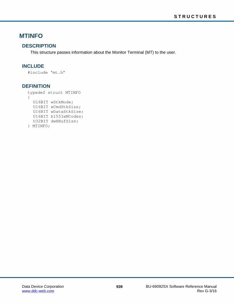
S T R U C T U R E S
Data Device Corporation BU-69092SX Software Reference Manual www.ddc-web.com Rev G-3/16
939
MTINFO DESCRIPTION
This structure passes information about the Monitor Terminal (MT) to the user.
INCLUDE #include “mt.h”
DEFINITION typedef struct MTINFO { U16BIT wStkMode; U16BIT wCmdStkSize; U16BIT wDataStkSize; U16BIT b1553aMCodes; U32BIT dwHBufSize; } MTINFO;

S T R U C T U R E S
Data Device Corporation BU-69092SX Software Reference Manual www.ddc-web.com Rev G-3/16
940
MTOPERATION DESCRIPTION
This structure describes the Monitor Terminal (MT) mode of operation.
INCLUDE #include “structs.h”
DEFINITION typedef struct MTOPERATION { U32BIT dwOptions; /* holds all register options set on config*/ U16BIT wStkMode; /* DOUBLE or SINGLE */ MTTRIGGER sTrig; /* Trigger Capture structure */ U16BIT wTrgStartState; /* TRUE if we should use trigger struct*/ U16BIT wTrgCurState; /* TRUE if we are currently not triggered */ U32BIT dwTrgWrdsHeld; /* Num of words to hold prior to trig*/ HOSTBUFFER sMTHBuf; /* MT Host Buffer */ HOSTBUFFER sRTMTHBuf; /* RTMT Host Buffer */ HOSTBUFFER sTmpRTHBuf; /* RT Temporary Host Buffer */ HOSTBUFFER sTmpMTHBuf; /* MT Temporary Host Buffer */ MTSTACK sStkA; /* AREA A stacks */ MTSTACK sStkB; /* AREA B stacks */ } MTOPERATION;

S T R U C T U R E S
Data Device Corporation BU-69092SX Software Reference Manual www.ddc-web.com Rev G-3/16
941
MTSTACK DESCRIPTION
This structure describes the Monitor Terminal (MT) stack.
INCLUDE #include “structs.h”
DEFINITION typedef struct MTSTACK { U32BIT dwCurrentMsg; /* Next message to be read off of stack */ U32BIT dwPrevTT; /* Previous processed Msg's HW TimeTag value */ U32BIT dwEndMsg; /* Last msg to be processed */ U32BIT dwLost; /* stack lost messages */ U16BIT wCmdSize; /* Size of the command stack(s) */ U32BIT dwCmdBase; /* First location of command stack 16->32*/ U32BIT dwCmdInit; /* Initial start loc for cmd stack 16->32*/ U32BIT dwCmdEnd; /* End location of command stack */ U16BIT wDataSize; /* Size of the data stack(s) */ U32BIT dwDataBase; /* First location of data stack */ U32BIT dwDataInit; /* Initial start loc for data stack */ U32BIT dwDataEnd; /* End location of data stack */ U32BIT dwHighPct; /* Highest Perecent ever full */ U32BIT dwPctFull; /* Current Percent full */ } MTSTACK;
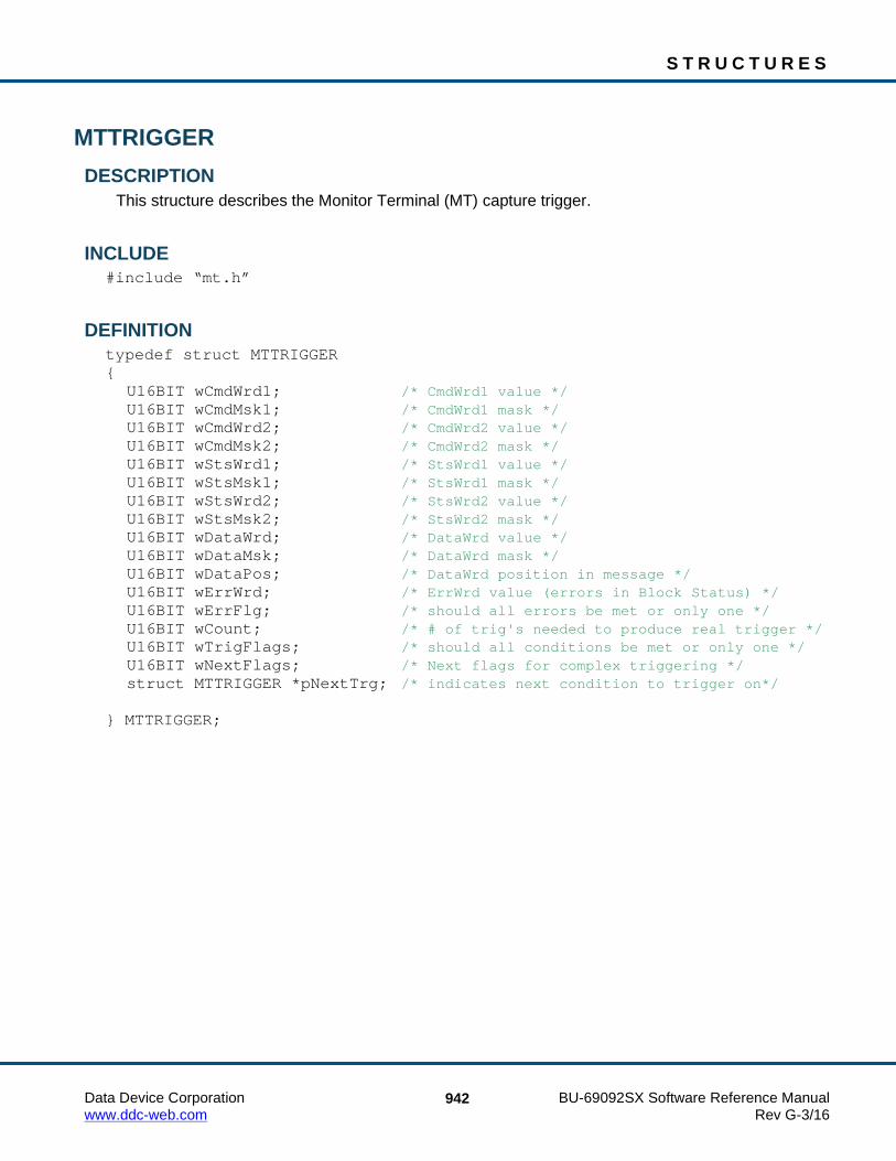
S T R U C T U R E S
Data Device Corporation BU-69092SX Software Reference Manual www.ddc-web.com Rev G-3/16
942
MTTRIGGER DESCRIPTION
This structure describes the Monitor Terminal (MT) capture trigger.
INCLUDE #include “mt.h”
DEFINITION typedef struct MTTRIGGER { U16BIT wCmdWrd1; /* CmdWrd1 value */ U16BIT wCmdMsk1; /* CmdWrd1 mask */ U16BIT wCmdWrd2; /* CmdWrd2 value */ U16BIT wCmdMsk2; /* CmdWrd2 mask */ U16BIT wStsWrd1; /* StsWrd1 value */ U16BIT wStsMsk1; /* StsWrd1 mask */ U16BIT wStsWrd2; /* StsWrd2 value */ U16BIT wStsMsk2; /* StsWrd2 mask */ U16BIT wDataWrd; /* DataWrd value */ U16BIT wDataMsk; /* DataWrd mask */ U16BIT wDataPos; /* DataWrd position in message */ U16BIT wErrWrd; /* ErrWrd value (errors in Block Status) */ U16BIT wErrFlg; /* should all errors be met or only one */ U16BIT wCount; /* # of trig's needed to produce real trigger */ U16BIT wTrigFlags; /* should all conditions be met or only one */ U16BIT wNextFlags; /* Next flags for complex triggering */ struct MTTRIGGER *pNextTrg; /* indicates next condition to trigger on*/ } MTTRIGGER;

S T R U C T U R E S
Data Device Corporation BU-69092SX Software Reference Manual www.ddc-web.com Rev G-3/16
943
OPCODEITEM DESCRIPTION
This structure contains information associated with an OpCode, software or hardware.
INCLUDE #include “structs.h”
DEFINITION typedef struct OPCODEITEM { U16BIT wOpCodeType; /* OpCode Type (XEQ, etc.) */ U16BIT wCondition; /* OpCode Condition */ U32BIT dwParameter1; /* OpCode Parameter1 */ U32BIT dwParameter2; /* OpCode Parameter2 */ U16BIT nOpCodeCount; /* Number of OpCodes in array */ S16BIT *paOpCodes; /* Pointer to array of OpCode IDs */ U32BIT dwReserved; /* Reserved */ U32BIT dwAceAddr; /* OpCode Location in ACE Mem */ U16BIT wAsyncAddr; /* Address of NOP following this opcode */ struct DLISTNODE *pMemNode; /* Pointer to memory node */ } OPCODEITEM;

S T R U C T U R E S
Data Device Corporation BU-69092SX Software Reference Manual www.ddc-web.com Rev G-3/16
944
OPCODESTRUCT DESCRIPTION
This structure defines opcode information for the Bus Controller (BC).
INCLUDE #include “bc.h”
DEFINITION typedef struct OPCODESTRUCT { S16BIT nOpCodeID; /* the unique ID of the OpCode */ U16BIT wOpCodeType; /* the type of opcode (constant)*/ U16BIT wParameter; /* Parameter of opcode */ U16BIT wCondition; /* Condition of opcode */ } OPCODESTRUCT;

S T R U C T U R E S
Data Device Corporation BU-69092SX Software Reference Manual www.ddc-web.com Rev G-3/16
945
REGSTATE DESCRIPTION
This structure contains the all registers that can be written to on an Enhanced Mini-ACE. Not supported for AceXtreme.
INCLUDE #include “structs.h”
DEFINITION typedef struct REGSTATE { U16BIT wIMR1; U16BIT wCFG1; U16BIT wCFG2; U16BIT wBCRTCtrl; U16BIT wTT; U16BIT wCFG3; U16BIT wCFG4; U16BIT wCFG5; U16BIT wRTMTDataStkAddr; U16BIT wBCFrmTimeRemain; U16BIT wBCRTMTMisc; U16BIT wCFG6; U16BIT wCFG7; U16BIT wBCGPF; U16BIT wIMR2; U16BIT wBCRTMTQP; U16BIT wRTBitWrd; } REGSTATE;
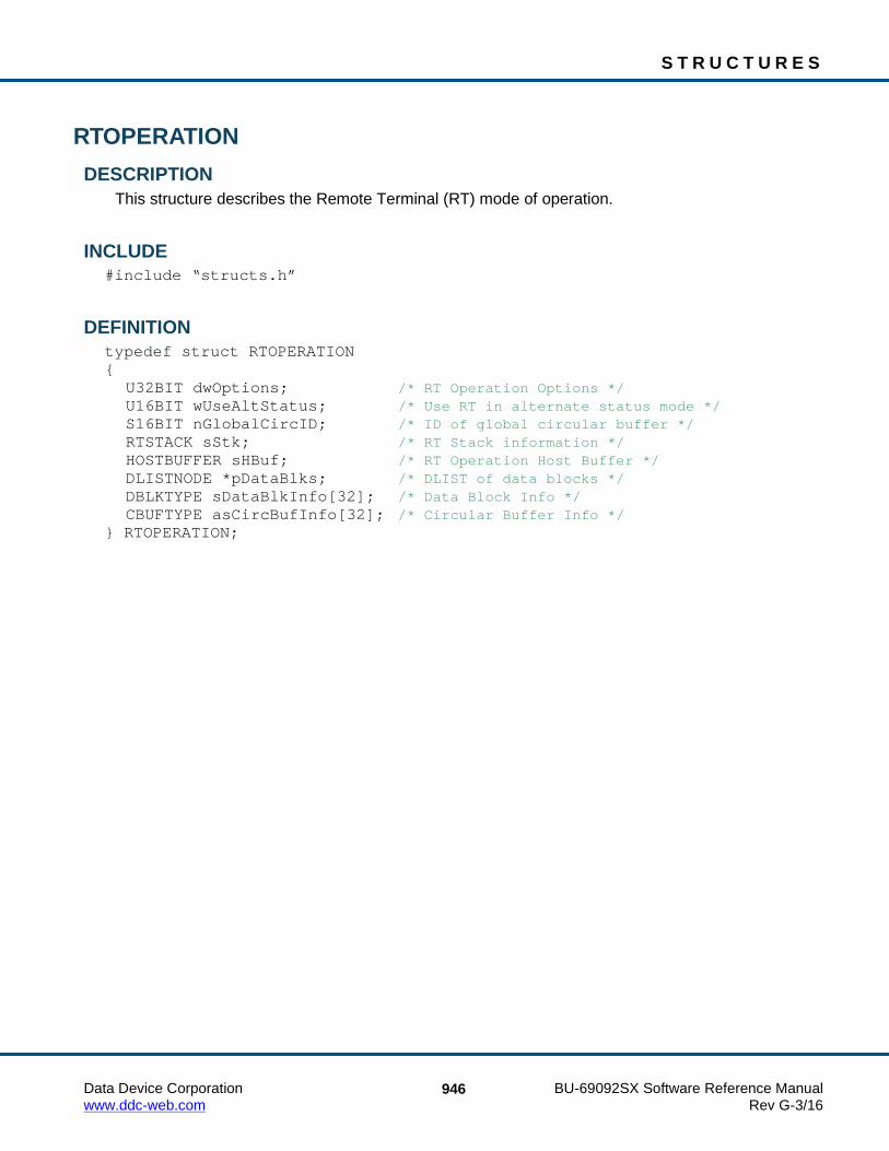
S T R U C T U R E S
Data Device Corporation BU-69092SX Software Reference Manual www.ddc-web.com Rev G-3/16
946
RTOPERATION DESCRIPTION
This structure describes the Remote Terminal (RT) mode of operation.
INCLUDE #include “structs.h”
DEFINITION typedef struct RTOPERATION { U32BIT dwOptions; /* RT Operation Options */ U16BIT wUseAltStatus; /* Use RT in alternate status mode */ S16BIT nGlobalCircID; /* ID of global circular buffer */ RTSTACK sStk; /* RT Stack information */ HOSTBUFFER sHBuf; /* RT Operation Host Buffer */ DLISTNODE *pDataBlks; /* DLIST of data blocks */ DBLKTYPE sDataBlkInfo[32]; /* Data Block Info */ CBUFTYPE asCircBufInfo[32]; /* Circular Buffer Info */ } RTOPERATION;

S T R U C T U R E S
Data Device Corporation BU-69092SX Software Reference Manual www.ddc-web.com Rev G-3/16
947
RTSTACK DESCRIPTION
This structure provides information of where, in memory, the card stack resides, as well as the size of the CMD Stack, and current message location. Statistics on the card stack are also part of this structure.
INCLUDE #include “structs.h”
DEFINITION typedef struct RTSTACK { U32BIT dwCmdBase; /* Start address of CMD stack 16 ->32 */ U32BIT dwCmdEnd; /* End address of command stack */ U16BIT wCmdSize; /* Size of the command stack */ U32BIT dwCurrentMsg; /* Current msg to process on cmd stk */ U32BIT dwPrevTT; /* Previous processed Msg's HW TimeTag value */ U32BIT dwEndMsg; /* Last msg to be processed */ U32BIT dwLost; /* Number of Stack Msgs lost */ U32BIT dwHighPct; /* Highest Perecent ever full */ U32BIT dwPctFull; /* Current Percent full */ } RTSTACK;

S T R U C T U R E S
Data Device Corporation BU-69092SX Software Reference Manual www.ddc-web.com Rev G-3/16
948
STKMETRIC DESCRIPTION
This structure defines valid performance information for an RT CmdStk.
INCLUDE #include “config.h”
DEFINITION typedef struct STKMETRIC { U32BIT dwLost; /* Total number of msgs lost since RT start */ U32BIT dwPctFull; /* Current Percentage of Cmd Stk used */ U32BIT dwHighPct; /* Highest Percentage of Cmd Stk used */ } STKMETRIC;

S T R U C T U R E S
Data Device Corporation BU-69092SX Software Reference Manual www.ddc-web.com Rev G-3/16
949
STREAMITEM DESCRIPTION
This structure contains all information associated with a data stream (BC).
INCLUDE #include “structs.h”
DEFINITION typedef struct STREAMITEM { U16 u16StreamType; /* Type of stream - 0=BCRT, 1=RTRT */ U16 u16SubAddrCount; /* RT Address 1 Subaddresses */ U16 u16RTAddr1; /* RT Address 1 */ U16 u16RTAddr2; /* RT Address 2 */ U16 u16MsgTime; /* Execution Time Of Message In uS */ U32 u32SubAddrMask1; /* RT Address 1 Subaddress Mask */ U32 u32SubAddrMask2; /* RT Address 2 Subaddress Mask */ U32 u32MsgBaseAddr; /* Base Address of Msg Memory Block */ U32 u32DataBaseAddr; /* Base Address of Data Memory Block */ U32 u32CtrlBlockArray[480]; /* 30 RT-RT Message Control Block Array (30 Blocks * 16 Dwords = 480 Dwords) */ struct DLISTNODE *pMemNode; /* pointer to memory node */ } STREAMITEM;

S T R U C T U R E S
Data Device Corporation BU-69092SX Software Reference Manual www.ddc-web.com Rev G-3/16
950
SWVERSIONINFO, PSWVERSIONINFO DESCRIPTION
This structure contains version information about the library.
INCLUDE #include “config.h”
DEFINITION typedef struct _SWVERSIONINFO { U32BIT dwRtlVersion; /* SDK version for specific OS */ U32BIT dwCoreVersion; /* Core version of code */ U8BIT szRtlVersion[32]; /* SDK version reported in a string format */ U32BIT dwReserved1; U32BIT dwReserved2; U32BIT dwReserved3; U32BIT dwReserved4; } SWVERSIONINFO, *PSWVERSIONINFO;

Data Device Corporation BU-69092SX Software Reference Manual www.ddc-web.com Rev G-3/16
951
7 APPENDIX A 7.1 Error and Warning Messages
The following section contains a list of the error/warning macros that are returned by the functions of the AceXtreme C SDK and the text that is associated with the error or warning. The error/warning macro can be converted with the aceErrorStr() function to the actual text.
ACE_ERR_SUCCESS Error Number: 0 Text: No error occurred Description: The function completed successfully.
ACE_ERR_TIMEOUT Error Number: 50 Text: A Timeout occurred Description: The function has expired a configured timeout. Solution: React to the function before the timeout expiration.
ACE_ERR_DATA_UNAVAILABLE Error Number: 51 Text: The requested data is unavailable Description: The data requested by the function is currently unavailable. Solution: Wait for data to become available and call function again.
ACE_ERR_BUFFER_OVERFLOW Error Number: 52 Text: Buffer Overflow Description: The function has detected a buffer overflow Solution: Call the function more often or reconfigure to avoid overflows.
ACE_ERR_BUFFER_UNAVAILABLE Error Number: 53 Text: Buffer Unavailable Description: The function has returned with no buffer Solution: Wait for data buffer to become available and call function again.

A P P E N D I X A
Data Device Corporation BU-69092SX Software Reference Manual www.ddc-web.com Rev G-3/16
952
ACE_ERR_INVALID_DEVNUM Error Number: -50 Text: Invalid device number Description: The device number parameter of the function call is not registered with
the system as being a valid device. Device numbers range from 0 – 31.
Solution: Select a device number that corresponds to an actual EMA / E²MA channel in the system.
ACE_ERR_INVALID_ACCESS Error Number: -51 Text: Invalid access type Description: The device was initialized with an access type (Simulate, Card Access, or
User memory) that is not consistent with the operation requested.
Solution: Close the device with the aceFree() function and re-initialize the device to the proper access usage using the aceInitialize() function.
ACE_ERR_INVALID_MODE Error Number: -52 Text: Invalid mode of operation Description: The device was initialized to a mode of operation (BC, RT, MT or RTMT)
that is not consistent with the operation requested. Solution: Select a correct operation or modify the mode of the device by closing it with
the aceFree() function and reinitialize with the aceInitialize() function.
ACE_ERR_INVALID_STATE Error Number: -53 Text: Invalid device state Description: The device is in an operation state (Ready or Run) that is not constant with
the operation requested. Solution: Modify the state of the device or select another operation that will work with
the current state.

A P P E N D I X A
Data Device Corporation BU-69092SX Software Reference Manual www.ddc-web.com Rev G-3/16
953
ACE_ERR_INVALID_MEMSIZE Error Number: -54 Text: Bad memory word size Description: The specified memory size is not valid. Solution: Verify that the memory size you are trying to pass in is valid and call the
function again.
ACE_ERR_INVALID_ADDRESS Error Number: -55 Text: Invalid device address Description: The application is attempting to access an address that is not associated
with either memory or registers for the selected device. Solution: Verify that the address being accessed is truly valid for the device.
ACE_ERR_INVALID_OS Error Number: -56
Text: Invalid Operating System
Description: The application is attempting to use functionality that is specific to a different operating system. Some of the functions in the SDK can only be performed in specific operating systems.
Solution: Verify that the function and the operating system are compatible.
ACE_ERR_INVALID_MALLOC Error Number: -57 Text: Memory allocation failed Description: The SDK attempted to create a data structure that requires dynamic
allocation of memory and the operation failed. This will usually be found in systems that have limited memory resources.
Solution: Suggest a smaller data structure if possible or add more memory to the system.
A P P E N D I X A
Data Device Corporation BU-69092SX Software Reference Manual www.ddc-web.com Rev G-3/16
954
ACE_ERR_INVALID_BUF Error Number: -58 Text: Invalid buffer Description: This error is returned when a SDK function requires a user supplied buffer.
If a buffer pointer is supplied in the parameter list of the function, but the buffer was never created, the ‘Invalid buffer’ error will be returned.
Solution: Declare and correctly create a buffer of the appropriate type and size for the operation being performed.
ACE_ERR_INVALID_ADMODE Error Number: -59 Text: Bad addressing mode Description: The way in which hardware registers and memory are being addressed is
incorrect. If you are running a DDC card product this value should never be changed in the SDK.
Solution: The address mode can be changed with the aceSetAddressMode() function, as long as you are in Advanced mode.
ACE_ERR_SIMWRITEREG Error Number: -60 Text: Invalid simulated write register Description: The SDK was not able to write to one of the simulated hardware registers. Solution: Reinstall SDK or complete installation.
ACE_ERR_TIMETAG_RES Error Number: -61 Text: Invalid time tag resolution Description: An invalid time tag resolution has been selected. Solution: Select a valid time tag resolution.
ACE_ERR_RESPTIME Error Number: -62 Text: Invalid response timeout value Description: A timeout response has occurred on the hardware. Solution: Try the function again or select a longer response time with the
aceSetRespTimeOut() function.

A P P E N D I X A
Data Device Corporation BU-69092SX Software Reference Manual www.ddc-web.com Rev G-3/16
955
ACE_ERR_CLOCKIN Error Number: -63 Text: Invalid clock input value Description: An invalid clock frequency has been selected or is being used. Solution: Try the function again or select a different clock frequency with the
aceSetClockFreq() function.
ACE_ERR_MSGSTRUCT Error Number: -64 Text: Invalid message structure Description: An invalid message structure has been specified. Solution: Try the function again and check to make sure the value of the message
structure is not NULL.
ACE_ERR_PARAMETER Error Number: -65 Text: Invalid parameter Description: An invalid parameter has been input by the user. Solution: Try the function again and make sure that the parameters are all within the
defined boundaries.
ACE_ERR_INVALID_MODE_OP Error Number: -66 Text: Invalid mode/options combination Description: An invalid mode has been selected by the user. Solution: Try the function again and make sure that you select one of the defined
modes of operation.
ACE_ERR_METRICS_NOT_ENA Error Number: -67 Text: Performance Metrics not enabled Description: The user has attempted to get metrics but metrics have not been enabled.
Solution: Call aceSetMetrics() to enable metrics and then try again.

A P P E N D I X A
Data Device Corporation BU-69092SX Software Reference Manual www.ddc-web.com Rev G-3/16
956
ACE_ERR_NOT_SUPPORTED Error Number: -68 Text: Function not supported in current Operating System Description: The function cannot be executed in current operating system, using
current hardware Solution: Use an alternate function, Operating System, or hardware
ACE_ERR_ISQ_DISABLED Error Number: -69 Text: ISQ Disabled, needs to be enabled for this function Description: The function requires the ISQ to be enabled. Solution: Enable the ISQ before calling this function.
ACE_ERR_TASK_FAIL Error Number: -70 Text: Task Priority Change Failed Description: An attempt to change the Interrupt task priority has failed Solution: Try changing the interrupt priority through the Operating System.
ACE_ERR_CANADDR Error Number: -71 Text: Invalid CAN Address Specified Description: An Invalid CANBus address has been supplied. Solution: Supply a valid CANBus address.
ACE_ERR_DIO Error Number: -72 Text: Invalid function setting. Change from HUB to DIO. Description: An attempt to use DIO in Hub mode has been made. Solution: Switch device to HUB mode.
A P P E N D I X A
Data Device Corporation BU-69092SX Software Reference Manual www.ddc-web.com Rev G-3/16
957
ACE_ERR_OVERFLOW Error Number: -73 Text: An overflow condition occurred Description: The function has detected an overflow condition Solution: Call the function more often or reconfigure to avoid overflow condition.
ACE_ERR_INITIALIZED Error Number: -74 Text: Device already initialized Description: The specified channel is already initialized. Solution: Avoid initializing channels more than once.
ACE_ERR_INVALID_SIZE Error Number: -75 Text: The specified size is outside of the allowable sizes Description: A size variable supplied to the function is outside the allowable range. Solution: Supply a size within the allowing range.
ACE_ERR_OPERATION Error Number: -76 Text: Operation Error Description: The request operation failed to execute. Solution: Make sure device support mode.
ACE_ERR_FREE_RESOURCE Error Number: -77 Text: Could not free resource Description: The attempt to free the allocated resources has failed. Solution: Check device status.
ACE_ERR_ALLOC_RESOURCE Error Number: -78 Text: Could not allocate resources Description: The attempt to free the allocated resources has failed. Solution: Check device status.

A P P E N D I X A
Data Device Corporation BU-69092SX Software Reference Manual www.ddc-web.com Rev G-3/16
958
ACE_ERR_REG_ACCESS Error Number: -80 Text: Unable to open Operating System registry key Description: The SDK and device driver were not able to access a required key in the
Operating System registry. This may be due to an incorrect or incomplete installation of the AceXtreme C SDK.
Solution: Reinstall AceXtreme C SDK or complete installation.
ACE_ERR_INVALID_CARD Error Number: -81 Text: Not a valid device Description: The device selected is not a valid device. Solution: Correct the device number allocation or select a different DevNum.
ACE_ERR_DRIVER_OPEN Error Number: -82 Text: Unable to open device driver Description: This error is usually due to inappropriate resource allocation for the device. Solution: Reinstall or correct device memory and interrupt allocation for system.
ACE_ERR_MAPMEN_ACC Error Number: -83 Text: Unable to access mapped memory Description: This error is usually due to inappropriate mapped resource in DOS or
VxWorks operating systems. Solution: Reinstall or correct mapped memory allocation for system.
ACE_ERR_NODE_NOT_FOUND Error Number: -100 Text: Element not found Description: The application requested that a data block be used that cannot be
located. Solution: Verify that the requested data block was previously created.

A P P E N D I X A
Data Device Corporation BU-69092SX Software Reference Manual www.ddc-web.com Rev G-3/16
959
ACE_ERR_NODE_MEMBLOCK Error Number: -101 Text: Element not a memory block Description: The application requested that a data block be used that is not in a valid
memory block. Solution: Verify that the requested data block was previously created. If it was,
destroy it and create it again.
ACE_ERR_NODE_EXISTS Error Number: -102 Text: Element is already defined Description: The function requested that a data block be created that has already been
previously defined. Solution: Verify that the requested data block was previously created. If it was, destroy
it and create it again or change the ID number on the new data block.
ACE_ERR_MEMMGR_FAIL Error Number: -150 Text: Not enough memory on device Description: An error has occurred in the creation or use of a block of memory. This
might be due to incorrect parameters of the function list (e.g. size or boundary conditions).
Solution: Verify that the parameters for the function are correct.
ACE_ERR_TEST_BADSTRUCT Error Number: -200 Text: Invalid test result structure Description: An invalid test result structure has been specified as an input to a function.
Solution: Verify that the parameters for the function are correct. Reinstall AceXtreme C SDK if the problem persists.

A P P E N D I X A
Data Device Corporation BU-69092SX Software Reference Manual www.ddc-web.com Rev G-3/16
960
ACE_ERR_TEST_FILE Error Number: -201 Text: Invalid file Description: An invalid or Null test file has been specified.
Solution: Verify that the parameters for the function are correct. Reinstall AceXtreme C SDK if the problem persists.
ACE_ERR_MT_BUFTYPE Error Number: -300 Text: Not a valid MT buffering mode Description: This error is returned if the application requests the use of a Monitor buffer
type that is inconsistent with the mode of operation or if the type does not exist.
Solution: Verify the monitor buffer type being requested is valid for the mode of operation.
ACE_ERR_MT_CMDSTK Error Number: -301 Text: Not a valid MT command stack size Description: The requested monitor command stack has an incorrect size. Solution: Verify the requested stack size is correct.
ACE_ERR_MT_DATASTK Error Number: -302 Text: Not a valid MT data stack size Description: The requested monitor data stack is being created with an incorrect size. Solution: Verify that the requested stack size is correct.
ACE_ERR_MT_FILTER_RT Error Number: -303 Text: Not a valid RT address Description: The specified RT address is outside of the valid range. Solution: Verify that the RT address is correct.

A P P E N D I X A
Data Device Corporation BU-69092SX Software Reference Manual www.ddc-web.com Rev G-3/16
961
ACE_ERR_MT_FILTER_TR Error Number: -304 Text: Not a valid T/R bit Description: The specified T/R bit is invalid. Solution: Verify that the T/R bit is correct.
ACE_ERR_MT_FILTER_SA Error Number: -305 Text: Not a valid subaddress buffer Description: The subaddress output parameter pointer is NULL. Solution: Recreate the pointer and make sure it is valid.
ACE_ERR_MT_STKLOC Error Number: -306 Text: Invalid MT stack location Description: The stack location is not valid. Solution: Please make sure the location is one of the following values:
ACE_MT_STKLOC_ACTIVE ACE_MT_STKLOC_INACTIVE ACE_MT_STKLOC_STKA ACE_MT_STKLOC_STKB
ACE_ERR_MT_MSGLOC Error Number: -307 Text: Invalid MT message location Description: The message location is not valid. Solution: Please make sure the location is one of the following values:
ACE_RT_MSGLOC_NEXT_PURGE ACE_RT_MSGLOC_NEXT_NPURGE ACE_RT_MSGLOC_LATEST_PURGE ACE_RT_MSGLOC_LATEST_NPURGE

A P P E N D I X A
Data Device Corporation BU-69092SX Software Reference Manual www.ddc-web.com Rev G-3/16
962
ACE_ERR_MT_HBUFSIZE Error Number: -308 Text: Not a valid host buffer size Description: The host buffer must be created with the correct size. (see the
aceMTInstallHBuf() function definition). Solution: Create a host buffer with the correct size.
ACE_ERR_MT_HBUF Error Number: -309 Text: Host buffer is not allocated Description: The host buffer is not created. Solution: Create a host buffer.
ACE_ERR_RTMT_COMBO_HBUF Error Number: -310 Text: Host buffer is RTMT combination Description: RTMT Host Buffer is enabled requiring the RTMT Host Buffer functions be
used. Solution: Use the RTMT Host Buffer functions instead.
ACE_ERR_RTMT_HBUFSIZE Error Number: -311 Text: Not a valid host buffer size Description: The supplied RTMT host buffer size is out of bounds. Solution: Supply a valid host buffer size.
ACE_ERR_RTMT_HBUF Error Number: -312 Text: Host buffer is not allocated Description: The RTMT Host Buffer has not been allocated Solution: Install the RTMT Host Buffer.
A P P E N D I X A
Data Device Corporation BU-69092SX Software Reference Manual www.ddc-web.com Rev G-3/16
963
ACE_ERR_RTMT_MSGLOC Error Number: -313 Text: Invalid RTMT message location Description: An invalid RTMT message location has been specified Solution: Specify a valid RTMT message location
ACE_WRN_RT_CFG_INVALID Error Number: 400 Text: RTs current config could cause M Prime first data word problem Description: Options may expose a known errata issue Solution: Use different options.
ACE_ERR_RT_DBLK_EXISTS Error Number: -400 Text: RT data block already defined Description: The defined data block ID already exists. Solution: Create the data block with a different ID.
ACE_ERR_RT_DBLK_ALLOC Error Number: -401 Text: RT data block allocation failed Description: System failed to allocate the data block Solution: Supply more host memory or use less data blocks.
ACE_ERR_RT_DBLK_MAPPED Error Number: -402 Text: RT data block is currently linked to a subaddress Description: The defined data block ID is already mapped to a subaddress. Solution: Unmap the data block and try again or choose another data block.
ACE_ERR_RT_DBLK_NOT_CB Error Number: -403 Text: RT data block is not a circular buffer Description: The specified data block is not a circular buffer. Solution: Choose another data block.

A P P E N D I X A
Data Device Corporation BU-69092SX Software Reference Manual www.ddc-web.com Rev G-3/16
964
ACE_ERR_RT_HBUF Error Number: -410 Text: RT host buffer is not allocated Description: The host buffer has not been allocated. Solution: Install the host buffer and try the operation again.
ACE_WRN_BC_OPCODE_INVALID Error Number: 500 Text: Selected OpCode condition could cause M Prime BC XEQ problem Description: Selected configuration may expose a known errata issue. Solution: Use different options.
ACE_ERR_BC_DBLK_EXISTS Error Number: -500 Text: BC data block already defined Description: The defined data block ID already exists. Solution: Create the data block with a different ID.
ACE_ERR_BC_DBLK_ALLOC Error Number: -501 Text: BC data block allocation failed Description: System failed to allocate BC data block. Solution: Supply more host memory or allocate less data blocks.
ACE_ERR_BC_DBLK_SIZE Error Number: -502 Text: Invalid BC data block size Description: The defined data block size is not valid. Solution: Create the data block with a proper size.
ACE_ERR_ UNRES_DATABLK Error Number: -503 Text: BC data block not defined Description: The specified data block has not been previously defined. Solution: Define the data block.

A P P E N D I X A
Data Device Corporation BU-69092SX Software Reference Manual www.ddc-web.com Rev G-3/16
965
ACE_ERR_ UNRES_MSGBLK Error Number: -504 Text: BC message block not defined Description: The specified message block has not been previously defined. Solution: Define the message block.
ACE_ERR_ UNRES_FRAME Error Number: -505 Text: BC frame block not defined Description: The specified frame block has not been previously defined. Solution: Define the frame block.
ACE_ERR_ UNRES_OPCODE Error Number: -506 Text: BC opcode block not defined Description: The specified opcode has not been previously defined. Solution: Define the opcode.
ACE_ERR_ UNRES_JUMP Error Number: -507 Text: Jump (JMP) address is out of frame range Description: The jump operation you are trying to perform is not valid. Solution: Verify that the jump parameter is correct and try again.
ACE_ERR_ FRAME_NOT_MAJOR Error Number: -508 Text: Selected frame is not a major frame Description: This is not a valid minor frame. Solution: Verify that the frame is correct or define major frame and try this operation
again.

A P P E N D I X A
Data Device Corporation BU-69092SX Software Reference Manual www.ddc-web.com Rev G-3/16
966
ACE_ERR_NOT_ASYNC_MODE Error Number: -509 Text: Asynchronous option not enabled Description: Asynchronous message mode has not been enabled. Solution: Enable Asynchronous messaging mode.
ACE_ERR_UNRES_ASYNC_OP Error Number: -510 Text: BC Aysnc OpCode block not defined Description: Attempt to send an undefined Asynchronous message. Solution: Define Asynchronous message before calling function.
ACE_ERR_UNRES_ASYNC_ID Error Number: -511 Text: BC Aysnc Msg ID not defined Description: Message ID for Asynchronous message is not defined. Solution: Defined Asynchronous message before calling function.
ACE_ERR_ASYNC_NOT_EMPTY Error Number: -512 Text: Can't reset pointer, Async list not empty Description: Cannot reset LP Asynchronous message queue before entries still exist. Solution: Empty LP queue before resetting.
ACE_ERR_ASYNC_MSG Error Number: -513 Text: Error sending asynchronous messages Description: An error occurred when attempting to send asynchronous messages. Solution: Check cabling.

A P P E N D I X A
Data Device Corporation BU-69092SX Software Reference Manual www.ddc-web.com Rev G-3/16
967
ACE_ERR_BC_DATA_ARRAY_IN_USE Error Number: -515 Text: BC Data Array is in use Description: The data array is already being used and cannot be reused. Solution: Finish the use of the data array before reusing.
ACE_ERR_BC_DATA_ARRAY_MSG_BUSY Error Number: -516 Text: BC Data Array async queue busy Description: The data array is already being used and cannot be reused. Solution: Finish the use of the data array before reusing.
ACE_ERR_BC_DATA_ARRAY_COMPLETE Error Number: -517 Text: BC Data Array transmission has completed Description: Data array transmission has completed and the transfer type is single. Solution: Change transfer type to ACEX_BC_ARRAY_TYPE_CONT if continuous
transmission is required.
ACE_ERR_BC_UNRES_MEMOBJECT Error Number: -518 Text: Memory Object not found Description: The memory object does not exist. Solution: Check memory object
ACE_ERR_BC_INVALID_EI_ERROR Error Number: -520 Text: Invalid BC error injection type Description: The error injection type passed into the ACEX_ERR_INJ structure is not
supported. Solution: Check the error injection type.

A P P E N D I X A
Data Device Corporation BU-69092SX Software Reference Manual www.ddc-web.com Rev G-3/16
968
ACE_ERR_ HBUFSIZE Error Number: -600 Text: Host buffer size is incompatible Description: The size of the host buffer is not valid. Solution: Please specify a valid size for the host buffer and try this operation again.
ACE_ERR_ HBUF Error Number: -601 Text: Host buffer is not allocated Description: The host buffer has not been installed. Solution: Please install the host buffer and try this operation again.
ACE_ERR_DISCRETE Error Number: -650 Text: Invalid discrete bit specified Description: An attempt to access an invalid Discrete bit. Solution: Verify the discrete bit.
ACE_ERR_DLEVEL Error Number: -651 Text: Invalid discrete level specified Description: Discrete level was not High or Low. Solution: Verify parameter passed in for discrete level.
ACE_ERR_TOO_MANY_DEVS Error Number: -700 Text: Too many devices allocated Description: This error occurs in VxWorks if too many devices are allocated for use. Solution: Please reset the system and allocate less.
MTI_ERR_EMPTY_QUEUE Error Number: -701 Text: MT-I Queue is empty Description: MT-I Queue is empty. Solution: Verify MT-I configuration.

A P P E N D I X A
Data Device Corporation BU-69092SX Software Reference Manual www.ddc-web.com Rev G-3/16
969
ACE_ERR_MEMMGR_MN_BLK_SIZE Error Number: -702 Text: MT-I memblock size too small Description: The MT-I memory block is not large enough for data. Solution: Increase the MT-I memory block.
MTI_ERR_STATE Error Number: -703 Text: MT-I state error Description: MT-I configuration is invalid. Solution: Verify MT-I configuration.
ACE_ERR_DMA_CHNL_REG Error Number: -704 Text: DMA Channel Reg error Description: A problem occurred due to DMA access. Solution: Verify card configuration.
ACE_ERR_DMA_QCALLOC Error Number: -705 Text: DMA Queue alloc error Description: A problem occurred due to DMA configuration. Solution: Verify DMA configuration.
ACE_ERR_DMA_REMOVE_CHANNEL Error Number: -706 Text: DMA error in request to remove chnl Description: A problem occurred with DMA when removing a channel. Solution: Verify configuration.
ACE_ERR_DMA_BUFFER_LENGTH Error Number: -707 Text: DMA error – buffer length Description: DMA buffer is not large enough. Solution: Increase the DMA buffer size.

A P P E N D I X A
Data Device Corporation BU-69092SX Software Reference Manual www.ddc-web.com Rev G-3/16
970
ACE_ERR_DMA_Q Error Number: -708 Text: DMA queue error Description: A problem occurred due to the DMA queue. Solution: Verify card configuration.
ACE_ERR_DMA_ZERO_BUFFER Error Number: -709 Text: DMA of zero length buffer Description: DMA buffer has a length of zero words. Solution: Verify DMA configuration.
ACE_ERR_MTI_PACKET_INVALID Error Number: -710 Text: Invalid BC error injection type Description: The error injection type passed into the ACEX_ERR_INJ structure is not
supported. Solution: Check the error injection type.
ACE_ERR_MTI_PACKET_EMPTY Error Number: -711 Text: The IRIG 106 Chapter 10 Data Packet does not contain any messages Description: The data packet does not contain a 1553 message. Solution: Check the data packet.
ACE_ERR_AVIONIC Error Number: -750 Text: Invalid Avionic Discrete bit specified Description: An attempt to access an invalid avionic bit. Solution: Verify the avionic bit.

A P P E N D I X A
Data Device Corporation BU-69092SX Software Reference Manual www.ddc-web.com Rev G-3/16
971
ACE_ERR_EMPTY_QUEUE Error Number: -751 Text: MIT Queue is empty Description: MT-I queue does not contain any data. Solution: Verify MT-I configuration.
ACE_RESOURCE_REQ_ERR Error Number: -800 Text: Unable to connect to IODevice Description: Library was unable to connect to IODevice driver. Solution: Make sure device driver is loaded in the kernel.
ACE_IOWRITE_ERR Error Number: -801 Text: Unable to write to IODevice Description: A write attempt to the IODevice has failed. Solution: Make sure device driver is loaded in the kernel.
ACE_IOREAD_ERR Error Number: -802 Text: Unable to read from IODevice Description: A read attempt from the IODevice has failed. Solution: Make sure device driver is loaded in the kernel.
ACE_MEM_MAP_ERR Error Number: -803 Text: Unable to map/unmap virtual memory Description: The SDK was unable to map or unmap virtual memory. Solution: Check that your kernel supports PCI virtual memory.
ACE_TASK_SPAWN_ERR Error Number: -804 Text: Unable to spawn task Description: The SDK was unable to spawn a support task. Solution: Make sure your kernel allows task creation.

A P P E N D I X A
Data Device Corporation BU-69092SX Software Reference Manual www.ddc-web.com Rev G-3/16
972
ACE_ERR_MTI_CH10_FILE_INVALID_MODE Error Number: -850 Text: Invalid file access mode. Description: Attempting to access a file in the wrong mode of operation. Solution: Check mode of operation.
ACE_ERR_MTI_CH10_FILE_INVALID_STATE Error Number: -851 Text: Invalid file state. Description: Attempting to access a file while it is already being used. Solution: Check file access.
ACE_ERR_MTI_CH10_FILE_INVALID_HANDLE Error Number: -852 Text: Invalid file handle Description: The handle to the file is incorrect. Solution: Check the handle parameter.
ACE_ERR_MTI_CH10_FILE_DATA_PKT_TOO_SMALL Error Number: -853 Text: Specified data packet size is too small. Description: The packet size is not large enough for the buffer. Solution: Check packet size.
ACE_ERR_MTI_CH10_FILE_INVALID_PKT Error Number: -854 Text: Invalid packet Description: The packet specified is incorrect. Solution: Check the packet.
ACE_ERR_MTI_CH10_FILE_NO_MORE_PKTS Error Number: -855 Text: No more packets Description: The file doesn’t contain any more data packets. Solution: Check the file.

A P P E N D I X A
Data Device Corporation BU-69092SX Software Reference Manual www.ddc-web.com Rev G-3/16
973
All unknown errors Unknown error number An error value was returned that has no defined meaning. Contact DDC if this error occurs. Please have as much information regarding the error and the circumstances that led to the error.
Data Device Corporation BU-69092SX Software Reference Manual www.ddc-web.com Rev G-3/16
974
8 APPENDIX B The three errors described in this appendix affect only RT and RT/Monitor modes of operation. The BC and Monitor (only) modes are not affected. Occurrences of these problems are very rare.
One error affects the first data word transmitted by the RT, while the other two errors affect the RT’s internal operations following receipt of specific mode code messages. These errors will only occur if all of the following configurations and conditions are in effect:
The 1553 terminal is operating in RT mode.
AND
One or more of certain specific non-message interrupts are enabled by the respective Interrupt Mask Register bit. The SDK functions that can set these interrupt conditions are aceSetIrqConditions(), aceRTInstallHBuf(), and aceRTMTInstallHBuf(). Please note that the use of a host buffer enables the time tag interrupt to periodically transfer messages and data from the card’s memory to your host buffer. These functions will return the ACE_WRN_RT_CFG_INVALID warning back to the user and will continue. The 1553 hardware’s non-message interrupts that are applicable are TIME TAG ROLLOVER, RT ADDRESS PARITY ERROR, and RAM PARITY ERROR.
AND
The interrupt status queue is enabled (i.e., bit 6 of Configuration Register #6 is logic “1” by calling aceISQEnable(TRUE)). In RT mode or RTMT mode the interrupt status queue is disabled by default.
AND, either
{The RT receives a non-mode code transmit command, or mode code transmit command involving a memory read operation for the transmitted data word. Receive commands to the RT are not affected.
AND
The internal write transfer to the interrupt status queue resulting from a non-message interrupt begins on a particular single clock cycle relative to the first data word read cycle; i.e., the read transfer from shared RAM and ensuing write to the internal Manchester encoder register.}
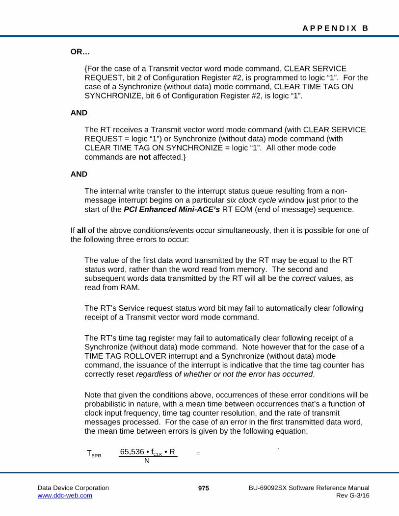
A P P E N D I X B
Data Device Corporation BU-69092SX Software Reference Manual www.ddc-web.com Rev G-3/16
975
OR…
{For the case of a Transmit vector word mode command, CLEAR SERVICE REQUEST, bit 2 of Configuration Register #2, is programmed to logic “1”. For the case of a Synchronize (without data) mode command, CLEAR TIME TAG ON SYNCHRONIZE, bit 6 of Configuration Register #2, is logic “1”.
AND
The RT receives a Transmit vector word mode command (with CLEAR SERVICE REQUEST = logic “1”) or Synchronize (without data) mode command (with CLEAR TIME TAG ON SYNCHRONIZE = logic “1”. All other mode code commands are not affected.}
AND
The internal write transfer to the interrupt status queue resulting from a non-message interrupt begins on a particular six clock cycle window just prior to the start of the PCI Enhanced Mini-ACE’s RT EOM (end of message) sequence.
If all of the above conditions/events occur simultaneously, then it is possible for one of the following three errors to occur:
The value of the first data word transmitted by the RT may be equal to the RT status word, rather than the word read from memory. The second and subsequent words data transmitted by the RT will all be the correct values, as read from RAM.
The RT’s Service request status word bit may fail to automatically clear following receipt of a Transmit vector word mode command.
The RT’s time tag register may fail to automatically clear following receipt of a Synchronize (without data) mode command. Note however that for the case of a TIME TAG ROLLOVER interrupt and a Synchronize (without data) mode command, the issuance of the interrupt is indicative that the time tag counter has correctly reset regardless of whether or not the error has occurred.
Note that given the conditions above, occurrences of these error conditions will be probabilistic in nature, with a mean time between occurrences that’s a function of clock input frequency, time tag counter resolution, and the rate of transmit messages processed. For the case of an error in the first transmitted data word, the mean time between errors is given by the following equation:
TERR =
65,536 • fCLK • R N

A P P E N D I X B
Data Device Corporation BU-69092SX Software Reference Manual www.ddc-web.com Rev G-3/16
976
For the case of the Service request status word bit or the Time Tag counter failing to clear, the mean time between errors is given by the following equation:
TERR =
where (for either equation):
TERR = average time between errors, in seconds fCLK = input clock frequency, in Megahertz (16 Megahertz for DDC cards) R = time tag resolution, in µS/LSB (default of 2 µS/LSB) N = number of transmit messages per second processed by the RT
For example, for an input clock frequency of 16 MHz, and a programmed time tag resolution of 64 µS/LSB, an error in the first transmitted word will occur (on average) once in every 226 = 67,108,864 transmit messages. For an RT responding to 100 transmit messages per second, this equates to (on average) one error every 671,089 seconds, or one error every 186 hours (7.8 days). Similarly, for an RT responding to 10 Transmit vector word or 10 Synchronize (without data) mode code messages per second, this equates to (on average) one error every 1,342,177 seconds, or one error every 373 hours (15.5 days). Note that in either case, the error is highly likely to be corrected following the RT’s next reception of a Transmit vector word or Synchronize (without data) mode command.
13107.2 • fCLK • R N

Data Device Corporation BU-69092SX Software Reference Manual www.ddc-web.com Rev G-3/16
977
9 INDEX API
aceBCAsyncMsgCreateBcst ...................... 166 aceBCAsyncMsgCreateBcstBCtoRT ........ 175 aceBCAsyncMsgCreateBcstMode ............ 169 aceBCAsyncMsgCreateBcstRTtoRT ........ 172 aceBCAsyncMsgCreateMode .................... 178 aceBCAsyncMsgCreateRTtoBC ............... 181 aceBCAsyncMsgCreateRTtoRT ................ 184 aceBCConfigure ........................................ 189 aceBCCreateImageFiles ............................ 192 aceBCDataBlkCreate ................................. 194 aceBCDataBlkDelete ................................. 197 aceBCDataBlkRead ................................... 199 aceBCDataBlkRead32 ............................... 201 aceBCDataBlkWrite .................................. 203 aceBCDecodeRawMsg .............................. 205 aceBCDisableMessage .............................. 209 aceBCEmptyAsyncList .............................. 187 aceBCExtTriggerDisable ........................... 211 aceBCExtTriggerEnable ............................ 212 aceBCFrameCreate .................................... 214 aceBCFrameDelete .................................... 218 aceBCFrmToHBuf ..................................... 220 aceBCFrmToHBuf32 ................................. 222 aceBCGetAsyncCount ............................... 224 aceBCGetConditionCode .......................... 226 aceBCGetGPQMetric ................................ 230 aceBCGetHBufMetric ............................... 232 aceBCGetHBufMsgCount ......................... 234 aceBCGetHBufMsgDecoded ..... 235, 426, 430 aceBCGetHBufMsgsRaw .......................... 238 aceBCGetMsgFromIDDecoded ......... 240, 433 aceBCGetMsgFromIDRaw ................ 243, 436 aceBCGetMsgHdrFromIDRaw ......... 245, 438 aceBCGetStatus ......................................... 247 aceBCGPQGetCount ................................. 249 aceBCGPQRead ........................................ 251 aceBCInstallHBuf ...................................... 253 aceBCMsgCreate ....................................... 255 aceBCMsgCreateBcst ................................ 265 aceBCMsgCreateBcstMode ....................... 274 aceBCMsgCreateBcstRTtoRT ................... 283 aceBCMsgCreateBCtoRT .......................... 292 aceBCMsgCreateMode .............................. 301
aceBCMsgCreateRTtoBC .......................... 310 aceBCMsgCreateRTtoRT .......................... 319 aceBCMsgDelete ....................................... 328 aceBCMsgGapTimerEnable ...................... 330 aceBCMsgModify ...................................... 332 aceBCMsgModifyBcst ............................... 336 aceBCMsgModifyBcstMode ..................... 339 aceBCMsgModifyBcstRTtoRT ................. 342 aceBCMsgModifyBCtoRT ........................ 345 aceBCMsgModifyMode ............................ 348 aceBCMsgModifyRTtoBC ........................ 351 aceBCMsgModifyRTtoRT ........................ 354 aceBCOpCodeCreate ................................. 357 aceBCOpCodeDelete ................................. 369 aceBCResetAsyncPtr ................................. 371 aceBCSendAsyncMsgHP .......................... 373 aceBCSendAsyncMsgLP ........................... 375 aceBCSetGPFState .................................... 377 aceBCSetMsgRetry .................................... 379 aceBCSetWatchDogTimer ......................... 382 aceBCStart ................................................. 384 aceBCStop ................................................. 386 aceBCUninstallHBuf ................................. 388 aceCmdWordCreate ..................................... 14 aceCmdWordParse ....................................... 16 aceDOSCreateDevice ................................ 891 aceDOSEnableSBMode ............................. 892 aceErrorStr ................................................... 18 aceFree ......................................................... 20 aceGetAioAll ............................................. 844 aceGetAioDir ............................................. 846 aceGetAioIn ............................................... 848 aceGetAioOut ............................................ 850 aceGetBSWErrString ................................... 22 aceGetChannelCount ................................... 25 aceGetCoreVersion ...................................... 27 aceGetDiscAll ............................................ 859 aceGetDiscDir ............................................ 861 aceGetDiscIn .............................................. 863 aceGetDiscOut ........................................... 865 aceGetHWVersionInfo ................................ 28 aceGetIRIGTx .............................................. 30 aceGetLibVersion ........................................ 32 aceGetMemRegInfo ..................................... 34

I N D E X
Data Device Corporation BU-69092SX Software Reference Manual www.ddc-web.com Rev G-3/16
978
aceGetMsgTypeString ................................. 36 aceGetSWVersionInfo ................................. 38 aceGetTimeTagValue .................................. 39 aceGetTimeTagValueEx .............................. 41 aceInitialize .................................................. 43 aceInt80Enable ............................................ 47 aceIOFree ..................................................... 49 aceIOInitialize .............................................. 51 aceISQClear ................................................. 53 aceISQEnable .............................................. 55 aceISQRead ................................................. 57 aceMemRead ............................................... 59 aceMemRead32 ........................................... 61 aceMemWrite .............................................. 63 aceMemWrite32 .......................................... 65 aceMTClearHBufTrigger .......................... 619 aceMTConfigure ........................................ 620 aceMTContinue ......................................... 624 aceMTCreateImageFiles ............................ 626 aceMTDecodeRawMsg ............................. 628 aceMTDisableRTFilter .............................. 631 aceMTEnableRTFilter ............................... 634 aceMTGetHBufMetric ............................... 637 aceMTGetHBufMsgCount ........................ 639 aceMTGetHBufMsgDecoded .................... 640 aceMTGetHBufMsgsRaw ......................... 643 aceMTGetInfo ............................................ 645 aceMTGetRTFilter .................................... 647 aceMTGetStkMetric .................................. 650 aceMTGetStkMsgDecoded ........................ 653 aceMTGetStkMsgsRaw ............................. 657 aceMTICh10FileClose ............................... 717 aceMTICh10FileGetOffset ........................ 718 aceMTICh10FileOpen ............................... 720 aceMTICh10FileRead ................................ 722 aceMTICh10FileSetOffset ......................... 724 aceMTICh10FileWrite ............................... 726 aceMTICh10TimeFmt ............................... 681 aceMTICh10TimePktEnable ..................... 683 aceMTIConfigure ...................................... 685 aceMTIContinue ........................................ 689 aceMTIDecodeRawMsg ............................ 691 aceMTIFreeCh10DataPkt .......................... 693 aceMTIFreeCh10TimePkt ......................... 695 aceMTIGetCh10DataPkt ........................... 697 aceMTIGetCh10TimePkt .......................... 699
aceMTIGetCh10TimeRange ...................... 701 aceMTIGetMetrics ..................................... 703 aceMTIInitiateHostIrq ............................... 705 aceMTInstallHBuf ..................................... 660 aceMTIPause ............................................. 707 aceMTISetCh10TimeRange ...................... 709 aceMTISetExternalClk .............................. 711 aceMTIStart ............................................... 713 aceMTIStop ............................................... 715 aceMTPause ............................................... 662 aceMTSetHBufTrigger .............................. 664 aceMTStart ................................................. 668 aceMTStkToHBuf ..................................... 670 aceMTStkToHBuf32 ................................. 672 aceMTStop ................................................. 674 aceMTSwapStks ........................................ 676 aceMTUninstallHBuf ................................. 678 aceRegRead ................................................. 67 aceRegRead32 ............................................. 69 aceRegWrite ................................................. 71 aceRegWrite32 ............................................. 73 aceResetTimeTag ......................................... 75 aceRTBITWrdConfig ................................ 472 aceRTBITWrdRead ................................... 475 aceRTBITWrdWrite .................................. 480 aceRTBusyBitsTblClear ............................ 485 aceRTBusyBitsTblSet ................................ 487 aceRTBusyBitsTblStatus ........................... 489 aceRTConfigure ......................................... 491 aceRTCreateImageFiles ............................. 496 aceRTDataBlkCircBufInfo ........................ 498 aceRTDataBlkCreate ................................. 500 aceRTDataBlkDelete ................................. 503 aceRTDataBlkMapToSA ........................... 505 aceRTDataBlkRead ................................... 508 aceRTDataBlkUnmapFromSA .................. 510 aceRTDataBlkWrite ................................... 512 aceRTDecodeRawMsg .............................. 514 aceRTGetAddress ...................................... 517 aceRTGetAddrSource ................................ 519 aceRTGetHBufMetric ................................ 521 aceRTGetHBufMsgCount ......................... 523 aceRTGetHBufMsgDecoded ..................... 525 aceRTGetHBufMsgsRaw .......................... 529 aceRTGetStkMetric ................................... 532 aceRTGetStkMsgDecoded ......................... 534

I N D E X
Data Device Corporation BU-69092SX Software Reference Manual www.ddc-web.com Rev G-3/16
979
aceRTGetStkMsgsRaw .............................. 537 aceRTInstallHBuf ...................................... 539 aceRTModeCodeIrqDisable ...................... 541 aceRTModeCodeIrqEnable ....................... 543 aceRTModeCodeIrqStatus ......................... 547 aceRTModeCodeReadData ....................... 549 aceRTModeCodeWriteData ...................... 551 aceRTMsgLegalityDisable ........................ 553 aceRTMsgLegalityEnable ......................... 556 aceRTMsgLegalityStatus ........................... 558 aceRTMTConfigure ................................... 586 aceRTMTGetHBufMetric .......................... 593 aceRTMTGetHBufMsgCount ................... 595 aceRTMTGetHBufMsgDecoded ............... 597 aceRTMTGetHBufMsgsRaw .................... 601 aceRTMTIConfigure ................................. 729 aceRTMTInstallHBuf ................................ 604 aceRTMTIStart .......................................... 734 aceRTMTIStop .......................................... 736 aceRTMTStart ........................................... 606 aceRTMTStkToHBuf ................................ 608 aceRTMTStkToHBuf32 ............................ 611 aceRTMTStop ............................................ 614 aceRTMTUninstallHBuf ........................... 616 aceRTRelatchAddr .................................... 561 aceRTSetAddress ....................................... 563 aceRTSetAddrSource ................................ 565 aceRTStart ................................................. 567 aceRTStatusBitsClear ................................ 569 aceRTStatusBitsSet .................................... 572 aceRTStatusBitsStatus ............................... 575 aceRTStkToHBuf ...................................... 577 aceRTStkToHBuf32 .................................. 579 aceRTStop .................................................. 581 aceRTUninstallHBuf ................................. 583 aceSetAddressMode .................................... 76 aceSetAioAll .............................................. 852 aceSetAioDir .............................................. 854 aceSetAioOut ............................................. 856 aceSetAsyncIsr ............................................ 78 aceSetCANIsr .............................................. 80 aceSetClockFreq .......................................... 82 aceSetDecoderConfig .................................. 84 aceSetDiscAll ............................................ 867 aceSetDiscDir ............................................ 869 aceSetDiscOut ............................................ 871
aceSetHubAddress ....................................... 87 aceSetIRIGTx .............................................. 89 aceSetIrqConditions ..................................... 91 aceSetIrqConfig ........................................... 99 aceSetMetrics ............................................. 101 aceSetRamParityChecking ......................... 103 aceSetRespTimeOut ................................... 105 aceSetTimeTagRes .................................... 107 aceSetTimeTagValue ................................. 109 aceSetTimeTagValueEx ............................ 111 aceTestCanEbrLoop ................................... 113 aceTestIrqs ................................................. 115 aceTestLoopBack ....................................... 117 aceTestMemory ......................................... 119 aceTestProtocol .......................................... 121 aceTestRegisters ........................................ 123 aceTestVectors ........................................... 125 aceTestVectorsStatic .................................. 127 aceVxCreateDevs ....................................... 874 aceVxCreateEBRDevs ............................... 875 aceVxCreateISADevs ................................ 877 aceVxEnableSBMode ................................ 878 aceVxGetDevInfo ...................................... 880 aceVxGetDevNum ..................................... 882 aceVxGetISADevInfo ................................ 884 aceVxSetIOPort ......................................... 886 aceVxSetPCIAddressInfo .......................... 887 aceVxSetTaskPriority ................................ 888 acexBCAsyncMsgSendHP ........................ 390 acexBCAsyncMsgSendLP ......................... 392 acexBCAsyncQueueInfoHP ...................... 394 acexBCAsyncQueueInfoLP ....................... 396 acexBCConfigureReplay ........................... 398 acexBCContinue ........................................ 401 acexBCDataArrayCreateBCtoRT .............. 402 acexBCDataArrayDelete ........................... 405 acexBCDataArraySend .............................. 407 acexBCDataStreamCreateBCRT ............... 409 acexBCDataStreamCreateRTRT ............... 411 acexBCDataStreamDelete.......................... 414 acexBCDataStreamReceive ....................... 416 acexBCDataStreamSend ............................ 418 acexBCDbcDisable .................................... 420 acexBCDbcEnable ..................................... 421 acexBCFrameCreate .................................. 422 acexBCGetStatusReplay ............................ 440

I N D E X
Data Device Corporation BU-69092SX Software Reference Manual www.ddc-web.com Rev G-3/16
980
acexBCImrTrigSelect ................................ 442 acexBCMemObjCreate .............................. 444 acexBCMemObjDelete .............................. 446 acexBCMemWrdCreate ............................. 448 acexBCMemWrdDelete ............................. 450 acexBCMemWrdRead ............................... 452 acexBCMemWrdWrite .............................. 454 acexBCMsgErrorDisable ........................... 456 acexBCMsgErrorEnable ............................ 457 acexBCOpCodeRead ................................. 458 acexBCOpCodeWrite ................................ 460 acexBCPause ............................................. 463 acexBCSetMsgError .................................. 464 acexBCSetRespTimeout ............................ 466 acexBCStartReplay .................................... 468 acexClrDiscConfigure ............................... 129 acexEITxShutdownDisable ....................... 130 acexEITxShutdownEnable ........................ 131 acexGetAmplitude ..................................... 132 acexGetCoupling ....................................... 134 acexMRTClearRTBusyBitsTbl ................. 740 acexMRTClearRTStatusBits ..................... 743 acexMRTConfigRTBITWrd...................... 749 acexMRTConfigure ................................... 746 acexMRTDataArrayCreate ........................ 752 acexMRTDataArrayDelete ........................ 755 acexMRTDataArraySend .......................... 757 acexMRTDataBlkMapToRTSA ................ 762 acexMRTDataBlkUnmapFromRTSA ....... 759 acexMRTDataStreamCreate ...................... 765 acexMRTDataStreamDelete ...................... 767 acexMRTDataStreamReceive .................... 769 acexMRTDataStreamSend ........................ 771 acexMRTDbcDisable ................................ 773 acexMRTDbcEnable .................................. 775 acexMRTDisableRT .................................. 777 acexMRTDisableRTModeCodeIrq ............ 779 acexMRTDisableRTMsgLegality .............. 781
acexMRTEnableRT ................................... 784 acexMRTEnableRTModeCodeIrq ............. 786 acexMRTEnableRTMsgLegality ............... 790 acexMRTGetModeCodeIrqStatus ............. 795 acexMRTGetRTBusyBitsTblStatus ........... 793 acexMRTGetRTMsgLegalityStatus .......... 797 acexMRTGetRTStatusBits ........................ 800 acexMRTImrMapToRTSA ........................ 802 acexMRTImrTrigSelect ............................. 834 acexMRTMsgErrorDisable ........................ 804 acexMRTMsgErrorEnable ......................... 806 acexMRTReadRTBITWrd ......................... 810 acexMRTReadRTModeCodeData ............. 808 acexMRTRespTimeDisable ....................... 815 acexMRTRespTimeEnable ........................ 817 acexMRTSetMsgError ............................... 819 acexMRTSetRespTime .............................. 821 acexMRTSetRespTimeout ......................... 823 acexMRTSetRTBusyBitsTbl ..................... 825 acexMRTSetRTStatusBits ......................... 828 acexMRTStart ............................................ 830 acexMRTStop ............................................ 832 acexMRTWriteRTBITWrd ........................ 836 acexMRTWriteRTModeCodeData ............ 841 acexSetAmplitude ...................................... 136 acexSetCoupling ........................................ 138 acexSetDiscConfigure ............................... 140 acexTRGConfigure .................................... 142 acexTRGDisable ........................................ 144 acexTRGEnable ......................................... 146 acexTRGEventDisable ............................... 148 acexTRGEventEnable ................................ 150 acexTRGEventSelect ................................. 152 acexTRGGetStatus ..................................... 155 acexTRGGetTimeTag ................................ 158 acexTRGReset ........................................... 160
headquarters ....................................................... 7 technical support ................................................ 7

Data Device Corporation BU-69092SX Software Reference Manual www.ddc-web.com Rev G-3/16
981
BU-69092SX Software Reference Manual Record of Change Revision Date Pages Description
A 7/2010 All Initial Release

Data Device CorporationLeadership Built on Over 50 Years of Innovation
Data Device Corporation (DDC) is the world leader in the design and manufacture of high-reliability data bus products, motion control, and solid-state power controllers for aerospace, defense, and industrial automation applications. For more than 50 years, DDC has continuously advanced the state of high-reliability data communications and control technology for MIL-STD-1553, ARINC 429, AFDX®, Synchro/Resolver interface, and Solid-State Power Controllers with innovations that have minimized component size and weight while increasing performance. DDC offers a broad product line consisting of advanced data bus technology for Fibre Channel networks; MIL-STD-1553 and ARINC 429 Data Networking cards, components, and software; Synchro/Resolver interface components; and Solid-State Power Controllers and Motor Drives.
DDC is a leader in the development, design, and manufacture of highly reliable and innovative military data bus solutions. DDC's Data Networking Solutions include MIL-STD-1553, ARINC 429, AFDX®, Ethernet and Fibre Channel. Each Interface is supported by a complete line of quality MIL-STD-1553 and ARINC 429 commercial, military, and COTS grade cards and components, as well as software that maintain compatibility between product generations. The Data Bus product line has been field proven for the military, commercial and aerospace markets.
DDC is also a global leader in Synchro/Resolver Solutions. We offer a broad line of Synchro/Resolver instrument-grade cards, including angle position indicators and simulators. Our Synchro/Resolver-to-Digital and Digital-to-Synchro/Resolver microelectronic components are the smallest, most accurate converters, and also serve as the building block for our card-level products. All of our Synchro/Resolver line is supported by software, designed to meet today's COTS/MOTS needs. The Synchro/Resolver line has been field proven for military and industrial applications, including radar, IR, and navigation systems, fire control, flight instrumentation/simulators, motor/motion feedback controls and drivers, and robotic systems.
As the world’s largest supplier of Solid-State Power Controllers (SSPCs) and Remote Power Controllers (RPCs), DDC was the first to offer commercial and fully-qualified MIL-PRF-38534 and Class K Space-level screening for these products. DDC’s complete line of SSPC and RPC boards and components support real-time digital status reporting and computer control, and are equipped with instant trip, and true I²T wire protection. The SSPC and RPC product line has been field proven for military markets, and are used in the Bradley fighting vehicles and M1A2 tank.
DDC is the premier manufacturer of hybrid motor drives and controllers for brush, 3-phase brushless, and induction motors operating from 28 Vdc to 270 Vdc requiring up to 18 kilowatts of power. Applications range from aircraft actuators for primary and secondary flight controls, jet or rocket engine thrust vector control, missile flight controls, to pumps, fans, solar arrays and momentum wheel control for space and satellite systems.
Product Families
Military | Commercial Aerospace | Space | Industrial
Data Bus | Synchro/Resolver Digital Conversion| Power Controllers | Motor Controllers
Certifications
Data Device Corporation is ISO 9001: 2008 and AS 9100, Rev. C certified.
DDC has also been granted certification by the Defense Supply Center Columbus (DSCC) for manufacturing Class D, G, H, and K hybrid products in accordance with MIL-PRF-38534, as well as ESA and NASA approved.
Industry documents used to support DDC's certifications and Quality system are: AS9001 OEM Certification, MIL-STD-883, ANSI/NCSL Z540-1, IPC-A-610, MIL-STD-202, JESD-22, and J-STD-020.

The information in this Manual is believed to be accurate; however, no responsibility is assumed by Data Device Corporation for its use, and no license or rights are granted by implication or otherwise in connection therewith. Specifications are subject to change without notice.
Outside the U.S. - Call 1-631-567-5700
United Kingdom: DDC U.K., LTD James House, 27-35 London Road, Newbury, Berkshire RG14 1JL, England Tel: +44 1635 811140 Fax: +44 1635 32264
France: DDC Electronique 84-88 Bd de la Mission Marchland 92411 Courbevoie Cedex, France Tel: +33-1-41-16-3424 Fax: +33-1-41-16-3425
Germany: DDC Elektronik GmbH Triebstrasse 3, D-80993 München, Germany Tel: +49 (0) 89-15 00 12-11 Fax: +49 (0) 89-15 00 12-22
Japan: DDC Electronics K.K. Dai-ichi Magami Bldg, 8F, 1-5, Koraku 1-chome, Bunkyo-ku, Tokyo 112-0004, Japan Tel: 81-3-3814-7688 Fax: 81-3-3814-7689 Web site: www.ddcjapan.co.jp
Asia: Data Device Corporation - RO Registered in Singapore Blk-327 Hougang Ave 5 #05-164 Singapore 530327 Tel: +65 6489 4801
Inside the U.S. - Call Toll-Free 1-800-DDC-5757
Headquarters and Main Plant 105 Wilbur Place, Bohemia, NY 11716-2426 Tel: (631) 567-5600 Fax: (631) 567-7358 Toll-Free, Customer Service: 1-800-DDC-5757
Web site: www.ddc-web.com
DATA DEVICE CORPORATIONREGISTERED TO:
ISO 9001:2008, AS9100C:2009-01EN9100:2009, JIS Q9100:2009
FILE NO. 10001296 ASH09
RE
GIS T E R E D F
IRM
®U
The first choice for more than 50 years—DDC DDC is the world leader in the design and manufacture of high reliability data interface products, motion control, and solid-state power controllers for aerospace, defense, and industrial automation.
Data Device Corporation