ACEC Civil 3D Users Group - Home | ACEC WI · ACEC Civil 3D Users Group Intersection modeling –...
21
ACEC Civil 3D Users Group Intersection modeling – FDM design Eric Arneson
-
Upload
nguyenmien -
Category
Documents
-
view
224 -
download
3
Transcript of ACEC Civil 3D Users Group - Home | ACEC WI · ACEC Civil 3D Users Group Intersection modeling –...

ACEC Civil 3D Users Group
Intersection modeling – FDM design
Eric Arneson

About the Speaker
• 7 yrs WisDOT design/construction• 7 yrs WisDOT GIS• 8 yrs WisDOT Methods Development
• Currently: 3D Technologies-Operations and Training Program Engineer

Learning Objectives
•Be able to use the WisDOT intersection dynamic blocks.
•Be able to use WisDOT subassemblies for rural intersections.
•Understand profile slope control.•Understand intersection objects.•Learn all steps in the workflow for a common rural intersection.

Driving concepts behind workflows
•FDM design standards•Responsive to design changes
• Create and maintain live connections between objects and files
•Single source of information• Modeling and plan sheets run off same objects
(no copies!)•Full use of software functionality and WisDOT customizations

Driving concepts behind training
•Basic training of concepts and functions (quick and light)• Move through quickly
•WisDOT workflows (full and deep)• Make realistic and detailed• Incorporate common project situations

FDM content for rural intersections
• Design• 11-10 Design Controls• 11-25 Intersections At Grade• SDD 9A1 At-Grade Side Road Intersections
• Civil 3D• 15-5-3 CADDS Directory and File Name Convention• 15-5-7 Design Models
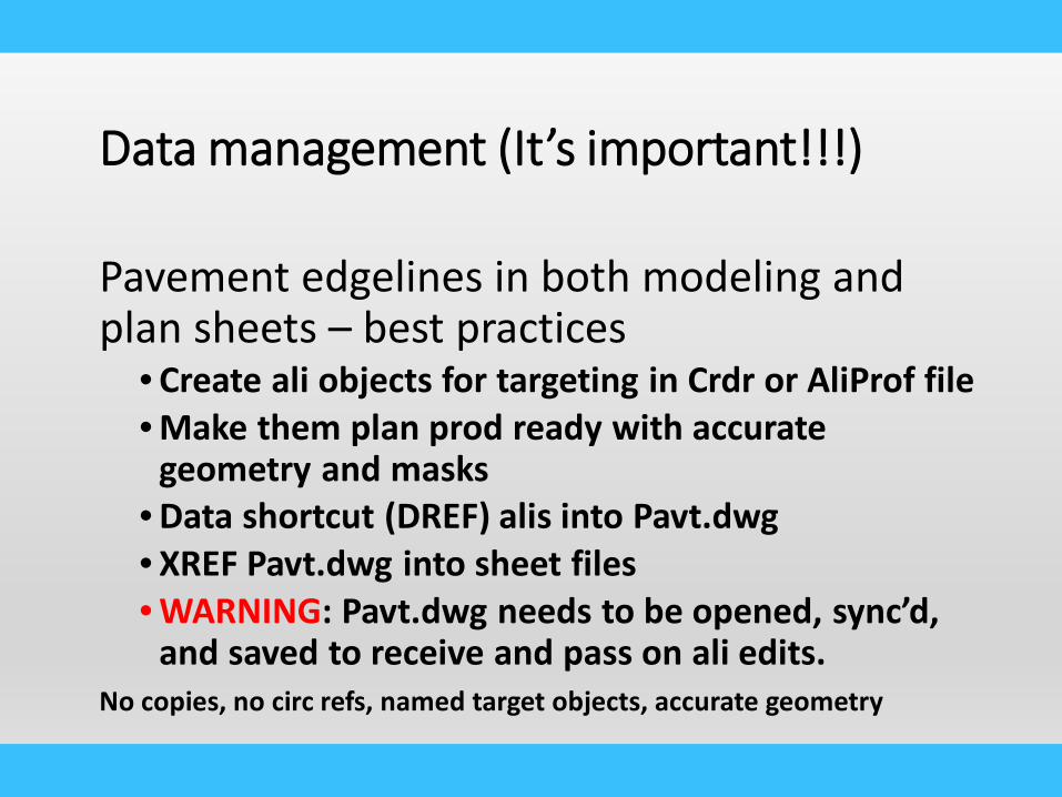
Data management (It’s important!!!)
Pavement edgelines in both modeling and plan sheets – best practices
• Create ali objects for targeting in Crdr or AliProf file• Make them plan prod ready with accurate
geometry and masks• Data shortcut (DREF) alis into Pavt.dwg• XREF Pavt.dwg into sheet files• WARNING: Pavt.dwg needs to be opened, sync’d,
and saved to receive and pass on ali edits.No copies, no circ refs, named target objects, accurate geometry
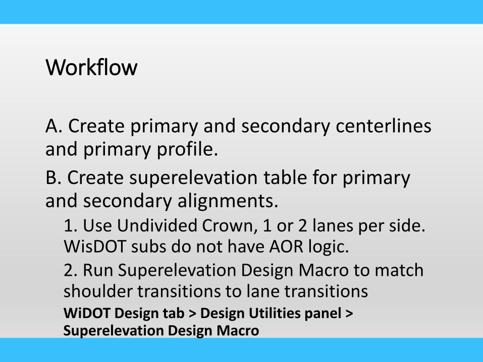
Workflow
A. Create primary and secondary centerlines and primary profile.B. Create superelevation table for primary and secondary alignments.
1. Use Undivided Crown, 1 or 2 lanes per side. WisDOT subs do not have AOR logic.2. Run Superelevation Design Macro to match shoulder transitions to lane transitionsWiDOT Design tab > Design Utilities panel > Superelevation Design Macro

Workflow
C. Create primary road edgeline geometry (ETW, EPS, EGS)D. In the corridor file, create references to data shortcuts 090.110.001 - Horizontal Geometry Development in the corridor drawing

Workflow
E. Create intersection horizontal geometry 090.110.002 - Horizontal Geometry Development - Corridor drawing
1. Use WisDOT intersection dynamic blocks. WiDOT Design tab > Parametric Design panel > Intersection blocks2. Key Concept: Create all intersection geometry (curb returns, turn lanes and tapers) as alis in the corridor dwg where the intersection is being designed. Typical roadway offsets like ETW, EPS and EGS have been developed as offset alignments in the AliProf dwg.

Workflow
3. Notes:- Curb return alignments run in the direction of the right turn- All other intersection alignments run in the same direction as the centerline of the road they reference- All intersection alignments are centerline type- Alignments and profiles created in the corridor files are only used in that corridor and not project wide- Alignments can be copied and renamed. Best practice to set all attributes (name, geometry, layer, style, masking) prior to copying.

Workflow
F. Secondary road centerline profile 090.110.003 -Vertical Geometry Development - Corridor drawing
1. Key Concept: Create secondary roadway centerline profile and lock down profile to the primary roadway and limits of construction using intersection objects2. Notes: Data reference a Lane Edge Setup Surface. This surface can be used to create surface profiles to use as targets by assemblies in the design corridor, and assign profile relationships with the intersection object

Workflow
G. Create ETW setup corridor 070.120 - Create Setup ETW surface
1. Key Concept: You cannot target something that is in the same corridor. This surface can now be used as a data reference in any drawing where you need to create an offset alignment profile that represents the cross slope and superelevation design.2. Notes: For downstream use in multiple corridor files

Workflow
H. Create curb return profile setup corridor 090.110.006 Curb Return Setup
1. Key Concept: create a setup corridor and setup surfaces for MIN, MAX, and NORMAL cross slopes for use in developing our design profiles on the curb returns

Workflow
I. Curb return profiles using intersection objects 090.110.007 - Intersection Objects to Synchronize Vertical Geometry - Curb Returns
1. Key Concept: set intersection objects on each curb return alignment. Each intersection object will use the ETW design profiles to define the end PVI elevations of the curb return design profiles. Setting 2 intersection objects will give tangents on each end of the curb return

Workflow
J. Add intersection assemblies to corridor dwg1. WisDOT Design tab > Assemblies & Subassemblies panel > WisDOT and Civil Imperial button > INTERSECTION-ASSEMBLIES tool palette
See corridor region layout map

Workflow
K. Create corridor1. See corridor region layout map2. Notes
Frequency defined in FDM 15-5-7Profile slope control is often best practice for final earthwork slope. Can be used for taper lane slopes as well.
3. Curb return regions(a) match parameters(b) for opposite side(c) update targets(d) add frequency(e) add section

Profile slope control
1. 080.180 Controlling corridor daylight slopes with profiles
2. Create profile with elevation = slope (i.e. 0.25 = 4:1)3. WisDOT Design tab > Assemblies & Subassemblies
panel > WisDOT & Civil Imperial tool > GENERAL tool palette
4. Insert ProfileParameterRef or MultiProfParameterRefinto assembly prior to the sub that it will be used in.
5. Parameter reference the value from the ProfRef sub into the slope variable.

Workflow
Notes:1. If different pavement structure than primary road,
need to edit 2. Once complete, split region at middle to get
triangles to fan out from curb flange3. Curb return assembly is right hand curve
(clockwise) aligned for placement

Workflow
L. Create corridor surfacesM. Create refinement surfacesN. Paste corridor surfaces into refinement surfacesO. Create any needed feature line/grading surfaces
1. Usually only needed for Top surface2. Ditches behind curb & gutter3. Curb ramps

ACEC Civil 3D Users Group
Thank You
Questions?Please remember to fill out your class surveys.


![[acec] - Microsoft Azure](https://static.fdocuments.in/doc/165x107/615754b01a137f629d6d36e4/acec-microsoft-azure.jpg)