AccuFlex™ VRF Application Training - HVAC · PDF fileNote each column’s heading...
55
AccuFlex™ VRF Application Training May 2015
Transcript of AccuFlex™ VRF Application Training - HVAC · PDF fileNote each column’s heading...

AccuFlex™ VRF Application Training
May 2015

1
Pre‐Design Checklist
Accurate Room/Zone Load Calculation
Building Blueprint or Drawing with Scale
Jobsite Voltage
Block Load Method
Room/Zone Load Method
Peak Zone Load Method
Load Calculations

2
Front Offices
8 Tons
West Office
4 Tons
East Office
4 Tons
• Block load = Room/Zone Load
Room/Zone LoadBlock Load
4 Tons 4 Tons
4 Tons 4 Tons
Mini‐Split Application
3
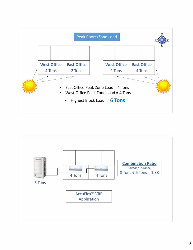
West Office
4 Tons
East Office
2 Tons
West Office
2 Tons
East Office
4 Tons
• East Office Peak Zone Load = 4 Tons• West Office Peak Zone Load = 4 Tons
6 Tons
Peak Room/Zone Load
• Highest Block Load =
4 Tons 4 Tons
6 Tons
AccuFlex™ VRF Application
Combination Ratio(Indoor / Outdoor)
8 Tons ÷ 6 Tons = 1.33

4
Highest Block Load occurring at hour 17…
236,067 Btu/h
Peak Zone Load regardless of thetime of day…
240,117 Btu/h
2249871080
2249871080
Size the outdoor unit to the highest block load
Size the indoor units to each peak zone load
• Total Peak Zone Load ÷ Highest Block Load = Combination Ratio
• 240,117 ÷ 236,067 = 1.02 Cooling Combination Ratio
5
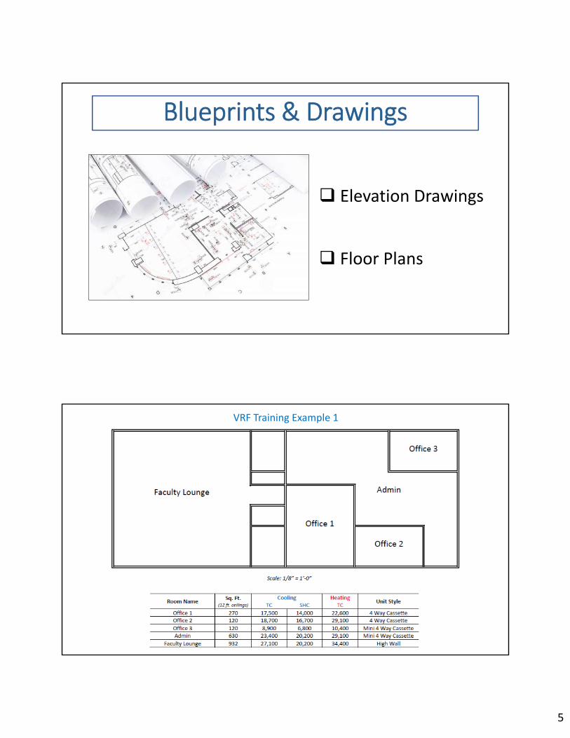
Elevation Drawings
Floor Plans
Blueprints & Drawings
VRF Training Example 1

6
Always download all available “Updates”
Click “Sales” to begin
Click “New” to start the design

7
Enter the project name
Select the design state then the city
Enter the customer’s information
Enter your information as the designer
Click “OK”
Double‐click in a cell to change it
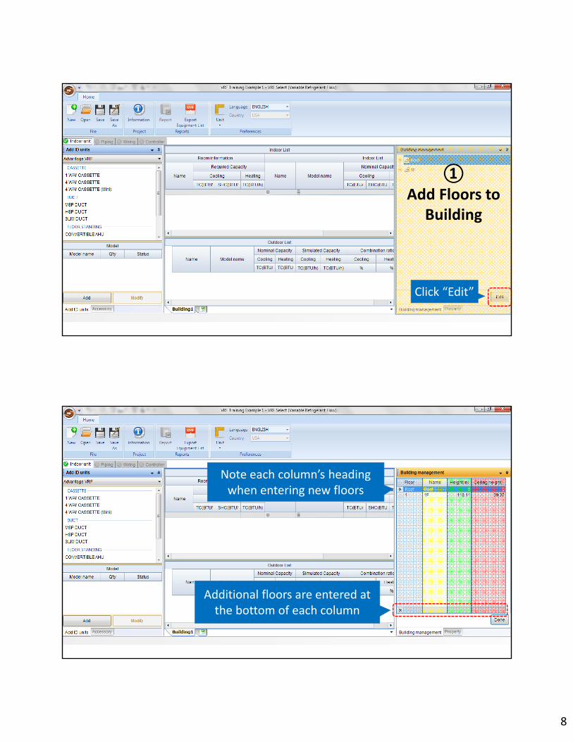
①Add Floors to
Building
②Add Rooms
&Loads
③Add Indoor
Units
④Add Indoor Accessories
⑤ Add Outdoor Units
⑥Locate Units In Building
8
①Add Floors to
Building
Click “Edit”
Note each column’s heading when entering new floors
Additional floors are entered at the bottom of each column
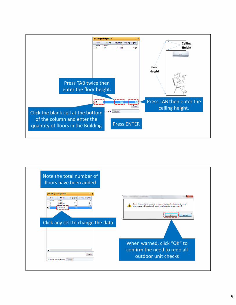
9
Click the blank cell at the bottom of the column and enter the
quantity of floors in the Building
Floor Height
CeilingHeight
Press TAB twice then enter the floor height.
Press TAB then enter the ceiling height.
Press ENTER
Click any cell to change the data
Note the total number of floors have been added
When warned, click “OK” to confirm the need to redo all
outdoor unit checks

10
To add a basement, enter ‐1 in the floor cell, press TAB to enter the heights, then press ENTER
After all floors are added or edited, click “Done”
To delete a floor, click to the the left of the floor on the arrow then press DELETE
②Add Rooms
&Loads

11
Double‐click the blank cell under “Name” then enter the first room (zone) name
Press TAB then enter the total cooling load
Press TAB then enter the sensible cooling load
Press TAB then enter the total heating load
Double‐click the next blank cell in the room column to enter the
next room
Enter all of the remaining rooms and loads in the building

12
To delete a room, select the name then
press DELETE Click “Yes” to confirm deleting the room
Double‐Click column line to see entire column content
③Add Indoor
Units

13
VRF Training Example 1VRF Training Example 1
To start the process of selecting the indoor units, select the first room name
14
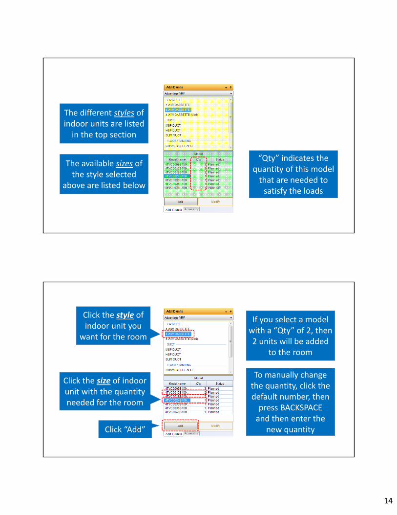
The available sizes of the style selected
above are listed below
The different styles of indoor units are listed in the top section
“Qty” indicates the quantity of this model that are needed to satisfy the loads
Click the style of indoor unit you
want for the room
Click the size of indoor unit with the quantity needed for the room
Click “Add”
If you select a model with a “Qty” of 2, then 2 units will be added
to the room
To manually change the quantity, click the default number, then press BACKSPACEand then enter the
new quantity

15
The indoor unit is now shown with the room
A yellow checkmark indicates an accessory has automatically been added,
in this case a cassette 4 way panel
Click the next room
Click the styleof indoor unit
Click “Add”
Click the size &quantity of unit

16
Click the styleof indoor unit
Click “Add”
Click the size &quantity of unit Click the
next room
Click the next room
Click the styleof indoor unit
Click “Add”
Click the size of unit with a quantity of 2

17
Note that 2 units were added to the room
Click the next room
Click the styleof indoor unit

18
Pause the mouse over the unit to see the
entire model number
For high wall indoor units, there appears to
be 2 of each size
Models ending in “B” need an external EEV. Models ending in “C” come with a factory
installed EEV
“High Wall” style has been selected
Click “Add”
Click the size of unit, with factory installed EEV and with a quantity of 2
19
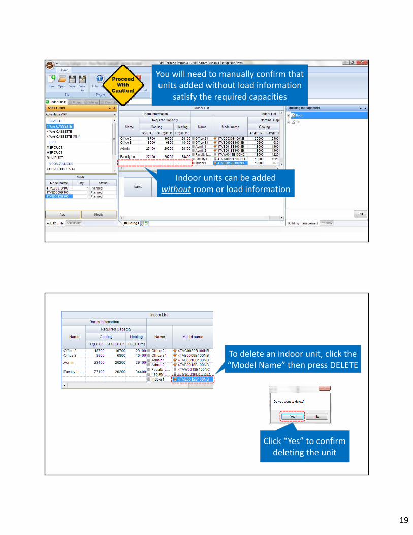
Indoor units can be added without room or load information
You will need to manually confirm that units added without load information
satisfy the required capacities
To delete an indoor unit, click the “Model Name” then press DELETE
Click “Yes” to confirm deleting the unit

20
Then click the indoor unit
To see the specifications of an indoor unit, click “Property” tab
To see all the indoor unitinformation click “Auto Hide”
Click the “Building Management” tab to return to the building

21
Click any tab to see the information again
You can also “Auto Hide” the “Add ID Units” section
Click “Auto Hide” to unhide the section

22
④Add Indoor Accessories
VRF Training Example 1VRF Training Example 1
23
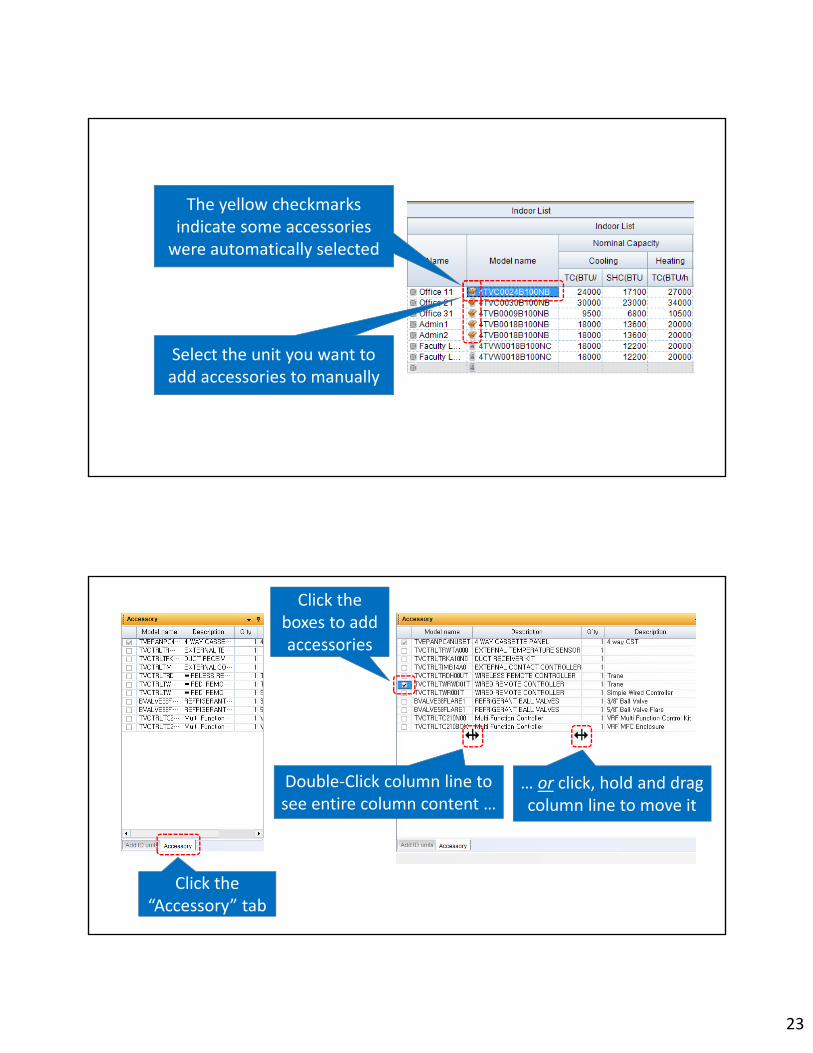
Select the unit you want to add accessories to manually
The yellow checkmarks indicate some accessories were automatically selected
Click the “Accessory” tab
Click the boxes to add accessories
… or click, hold and drag column line to move it
Double‐Click column line to see entire column content …
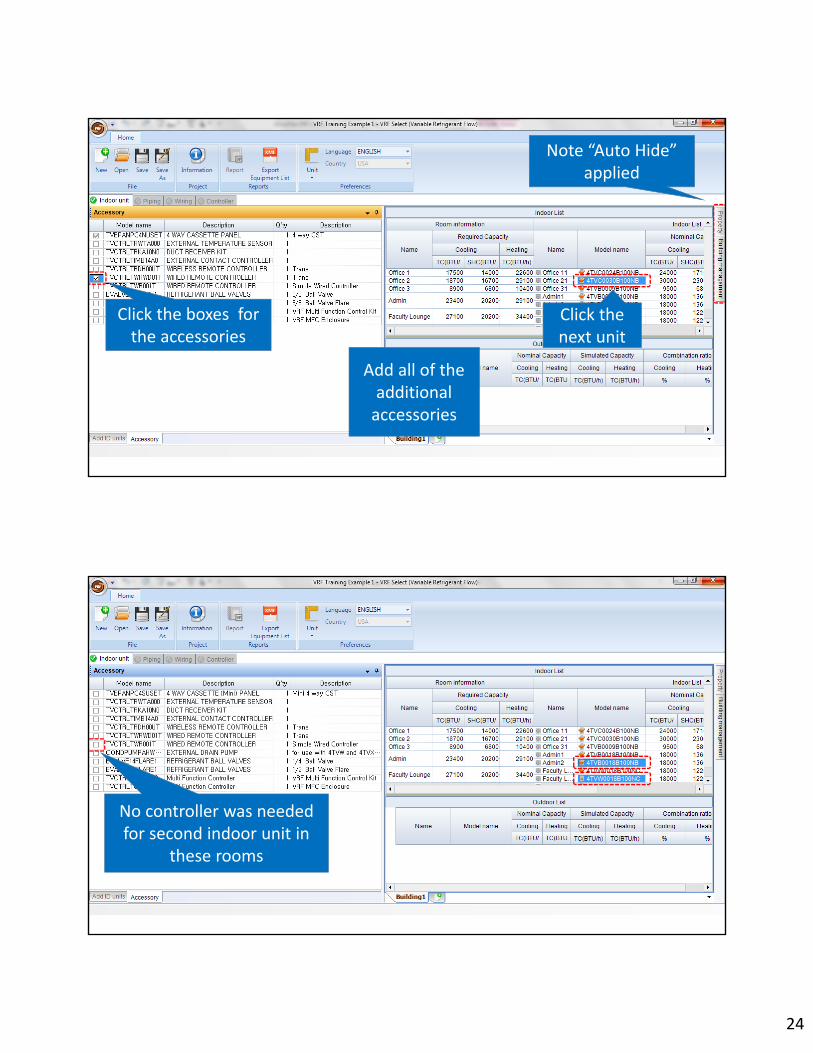
24
Click the next unit
Click the boxes for the accessories
Add all of the additional accessories
Note “Auto Hide” applied
No controller was needed for second indoor unit in
these rooms

25
⑤ Select Outdoor Units
Note “Auto Hide” was turned off
Note “Auto Hide” applied

26
Click the first unit to be connected to the outdoor unit
Press and hold CTRL then click the other indoor units
connected to the outdoor unit
Pressing SHIFT in place of CTRL will select all units up to the second selection
Once all the indoor units are selected, click the group and hold
Drag the group down to the “Outdoor List” and release
the mouse button
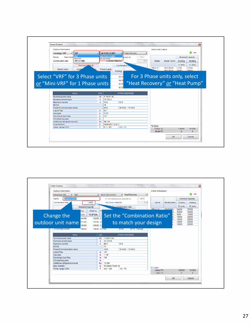
27
Select “VRF” for 3 Phase units or “Mini‐VRF” for 1 Phase units
For 3 Phase units only, select “Heat Recovery” or “Heat Pump”
Change the outdoor unit name
Set the “Combination Ratio” to match your design

28
Size the outdoor unit to the highest block load
Size the indoor units to each peak zone load
Non‐Hourly Zone Load CalculationZone Load = Block Load
Combination Ratio = 1.00
To remove an indoor unit from this system, click the
model then the – minus sign
Click “OK”
Click the outdoor model for the project

29
The outdoor unit is now shown
A green checkmark indicates the indoor unit is attached to the outdoor unit
Click “Yes” to confirm deleting the unit
To delete an outdoor unit, click the “Model Name” then press DELETE
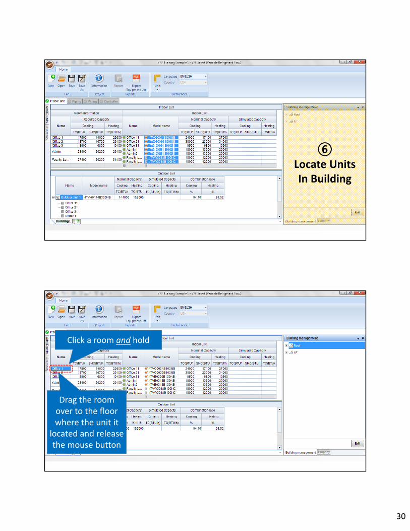
30
⑥Locate Units In Building
Drag the room over to the floor where the unit it
located and release the mouse button
Click a room and hold
31
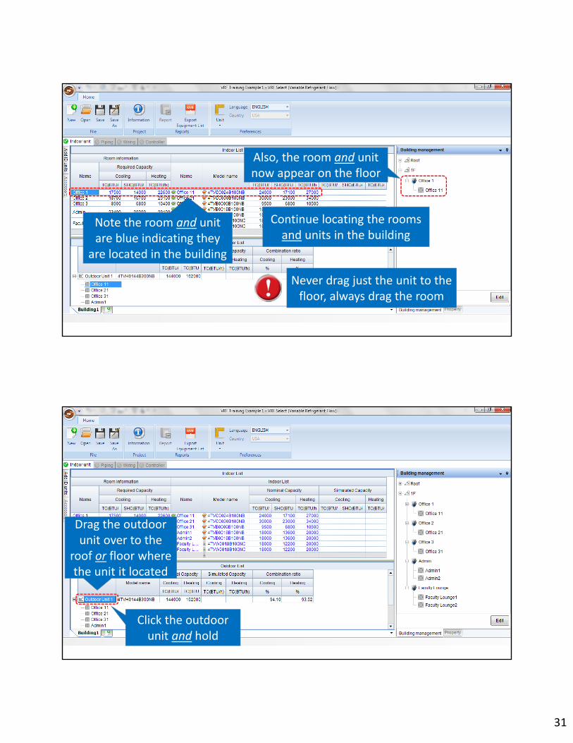
Continue locating the rooms and units in the building
Also, the room and unit now appear on the floor
Note the room and unit are blue indicating they
are located in the building
Never drag just the unit to the floor, always drag the room
Click the outdoor unit and hold
Drag the outdoor unit over to the
roof or floor where the unit it located

32
Select the “Piping” tab to begin laying out the refrigerant piping
A green checkmark means the piping for the system can now be designed
Note the outdoor unit now appears
Note that “Auto” is checked
“Auto” will create a piping system automatically for
heat pump systems

33
VRF Training Example 1
Empty boxes indicate a component can be located here
Select and drag a “Branch Joint” or “Header” to the empty box
Check “Manual” to lay out the piping according to the project

34
Magnifying glass features are also available
Use the mouse’s thumbwheel to increase ordecrease the drawing Size
Press & hold the mouse’s thumbwheel to move the drawing around the page
Right‐click in the empty box to see the available indoor units
Select the indoor unit for this location
35
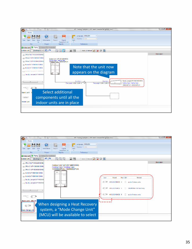
Note that the unit now appears on the diagram
Select additional components until all the indoor units are in place
When designing a Heat Recovery system, a “Mode Change Unit” (MCU) will be available to select
When designing a Heat Recovery system, a “Mode Change Unit” (MCU) will be
available to select

36
To see the specifications of any unit, click the unit
Click and hold the left border then drag it to enlarge the section

37
Right‐click on a component to remove it from the drawing
Click a section of pipe which then turns red
Click the “Actual Piping Length” box and enter the length
Click the “No. of Elbows” box and enter the quantity
Actual Length/Equivalent Length/Elbows(“Equivalent Length” & “Pipe Size” calculated during “System Check”

38
Click each section of pipe and enter the length and elbows
After all lengths and elbows are entered, click “System Check” to check the piping
Review all of the system piping checks.
Note the additional refrigerant charge
Double‐click or drag the column line to expand it
39
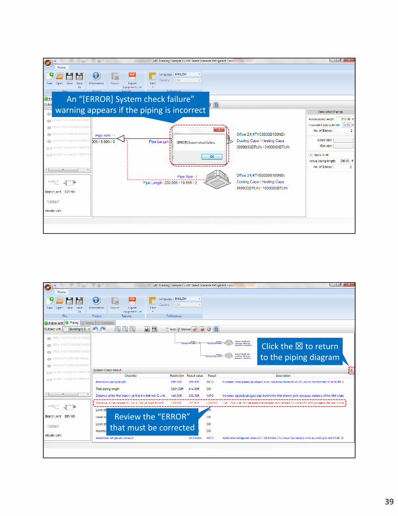
An “[ERROR] System check failure” warning appears if the piping is incorrect
Review the “ERROR” that must be corrected
Click the to return to the piping diagram

40
After all corrections are made, click “System Check”
to recheck the piping
After confirming a successful system check, click “Capacity Correction”

41
Note the outdoor unit “Simulated
Capacity”
Click“Capacity Correction”
Note the indoor unit “Simulated
Capacity”
Select “OK”
Click the “Indoor Unit” tab to review the simulated capacities

42
Note “Auto Hide” applied
Note “Auto Hide” applied
You may need to modify the indoor unit size if the simulated capacity does not satisfy the room Load
Click the “Model Name” of the unit you want to modify
Click the style of the unit
Click “Modify”
Click the size of the unit

43
Since the system capacity has changed, reselect the outdoor unit that meets the new load
Click “OK”
If you forget to reselect “Heat Pump” you will have to redo the piping layout
Note new indoor unit size
Click “Piping” to rerun “System Check”

44
Click “System Check” to recheck the piping
After confirming a successful system check, click “Capacity Correction”
To print the piping diagram, click “Print”

45
Note the updated outdoor unit “Simulated Capacity”
Click“Capacity Correction”
Note the updated indoor unit “Simulated Capacity”
Select “OK”
Confirm the updated simulated capacities satisfy the room loads

46
Note the amp draw and circuit protection is listed for each circuit
The amp draw of the field installed electric heat option in 4TVM air
handlers are not included
Click the “Wiring” tab to view a simple system wiring diagram
Click the “Breaker Name” or “Breaker Size” box to edit the information
Click a fuse or breaker
47
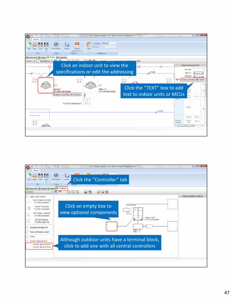
Click an indoor unit to view the specifications or edit the addressing
Click the “TEXT” box to add text to indoor units or MCUs
Click an empty box to view optional components
Although outdoor units have a terminal block, click to add one with all central controllers
Click the “Controller” tab

48
Click the yellow dot to connect a controller to the R1/R2 control layer
Click a central controller to add it to the system
Note the yellow dot turns red indicating a pending connection
Right‐click on a component to
remove or move it

49
Click “System Check” to check the control system
Click “OK”
Any controller errors will appear at the bottom
Select any tab to review or update the design
50
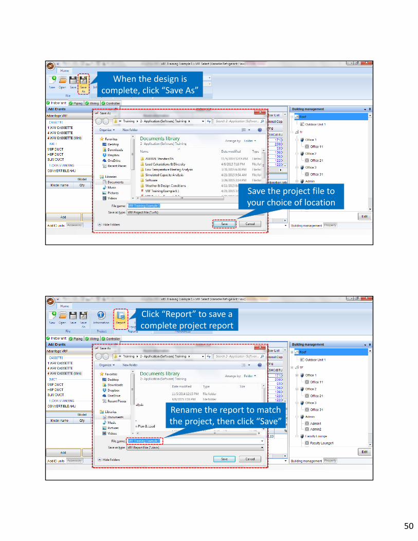
When the design is complete, click “Save As”
Save the project file to your choice of location
Click “Report” to save a complete project report
Rename the report to match the project, then click “Save”
51
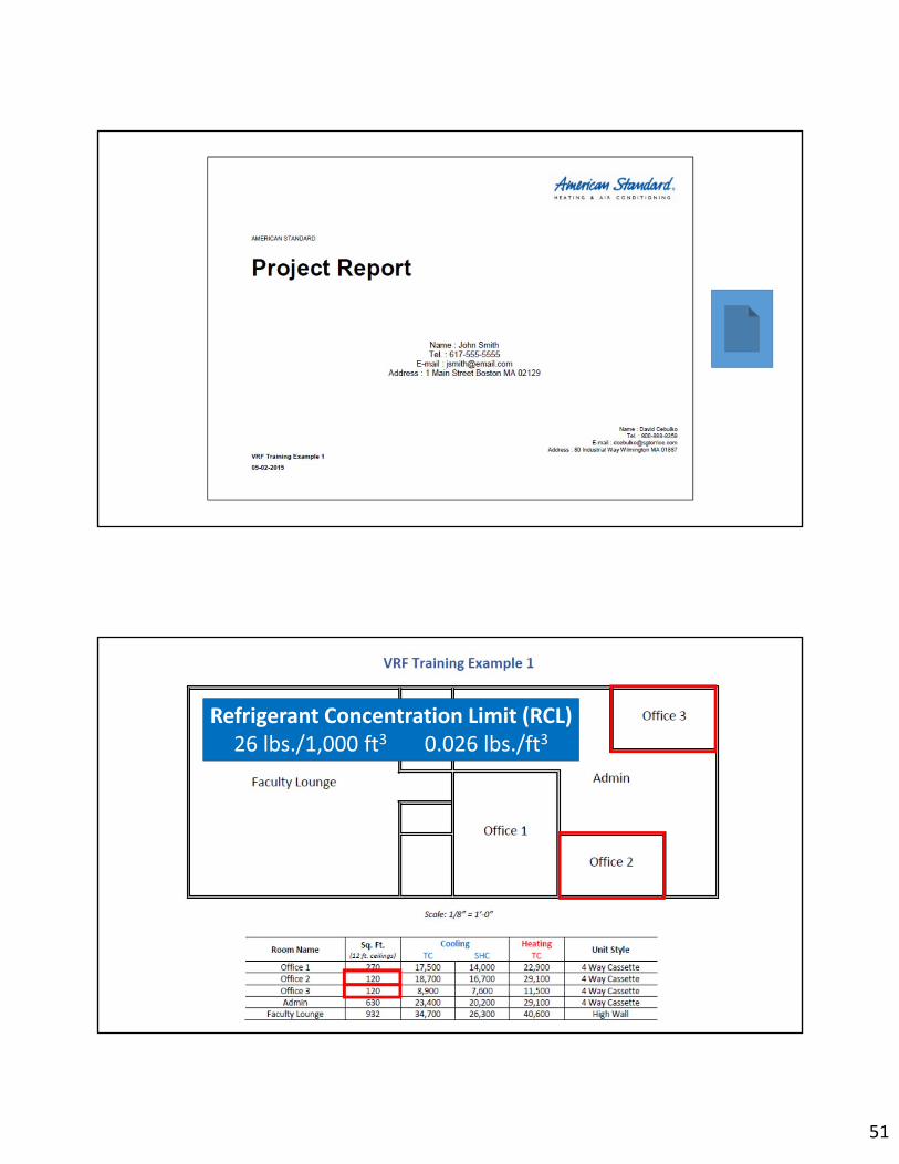
Refrigerant Concentration Limit (RCL) 26 lbs./1,000 ft3 0.026 lbs./ft3

52
• Total System Charge = 39.308 lbs.
• 39.308 ÷ 0.026 = 1512 ft3 minimum volume
• 1512 ft3 x 12 ft. = 126 ft2 minimum square feet
• Smallest Room = 120 ft2
• Solutions?• Possibly louvers, transfer grilles, undercut doors –need engineer/inspector approval
• 2 Smaller Systems in Place of 1
Refrigerant Concentration Limit (RCL) 26 lbs./1,000 ft3 0.026 lbs./ft3
Thank You for AttendingAmerican Standard AccuFlex™
Application Training

AccuFlex™ VRF
Massachusetts Default Design Conditions
\

New Hampshire Default Design Conditions
Rhode Island Default Design Conditions