AccessTouchTM - farnell.com · X1 Piezo buzzer, e.g. CMT-1603 How It Works The touch pads measure...
4
p1 of 4 7-Sep-08 Access-Touch HW140-1 www.firmwarefactory.com AccessTouch TM Touch sensitive keyed access controller Summary AccessTouch is an integrated combination key access controller featuring tough-sensitive keys for vandal-proof operation. An accompanying design blueprint is available for a complete low cost, access control product. AccessTouch uses capacitive touch sensing technology. The PCB keyboard shown can be overlaid by a non-metallic covering. It automatically calculates signal averages to compensate for track capacitance, water splashes, etc. A buzzer output provides audio feedback as buttons are pressed. AccessTouch is firmware for the PIC16F631 microcontroller and is available as a pre- programmed chip from electronics distributors or as a firmware download from www.hexwax.com. User Operation When the correct code is entered, the door release output is activated for a fixed time delay. The sequence of keys pressed prior to entering the code is unimportant. To change the access code, an electrical switch is closed and the new code is entered twice. LEDs indicate ‘Open’, ‘Closed’ and ‘Set Code’ states. All LEDs turn off when the device enters a sleep state. Features Tiny volume BOM cost Vandal-proof design, no parts need to be physically exposed Codes may be up to 8 digits Audio feedback on touch press Safe Controller mode available 20-pin SSOP package Electrical Specifications Table 1. Electrical Specifications Supply voltage Vdd 2.0 – 5.5 VDC Current, sleep scan mode, 3V Vdd ~50μA Operating Temperature –40°C to 85°C Firmware Factory Ltd 2 Marshall St, 3 rd Floor London W1F 9BB, UK [email protected] [email protected] Typical Application Circuit . Rst# PGD Vdd Vss TEAclipper connector 1 5 Lock Figure 1 Access Touch 2 3 4 Vdd Vss Touch0 C1 C2 Vss TouchA Vdd R10 To lock driver Touch0 TouchB Touch1 Touch2 Touch3 R1 R4-R7 TouchD .... . . . . . . .. Lock# R9 R8 . . TouchC Vdd Set . . . J1 R2 R3 C3 Vss Click1 Click2 BZ1 Touch0 Touch2 1 2 3 4 5 6 7 8 9 0 . . . . Touch1 Touch1 . Vss Touch3 .. Vss Typical touch pad layout SetLED OpenLED ClosedLED R11 LED1-3 R12
Transcript of AccessTouchTM - farnell.com · X1 Piezo buzzer, e.g. CMT-1603 How It Works The touch pads measure...

p1 of 4 7-Sep-08 Access-Touch HW140-1 www.firmwarefactory.com
AccessTouchTM
Touch sensitive keyed access controller
Summary
AccessTouch is an integrated combination key access controller featuring tough-sensitive keys for vandal-proof operation. An accompanying design blueprint is available for a complete low cost, access control product.
AccessTouch uses capacitive touch sensing technology. The PCB keyboard shown can be overlaid by a non-metallic covering. It automatically calculates signal averages to compensate for track capacitance, water splashes, etc. A buzzer output provides audio feedback as buttons are pressed.
AccessTouch is firmware for the PIC16F631microcontroller and is available as a pre-programmed chip from electronics distributors or as a firmware download from www.hexwax.com.
User Operation
When the correct code is entered, the door release output is activated for a fixed time delay. The sequence of keys pressed prior to entering the code is unimportant.
To change the access code, an electrical switch is closed and the new code is entered twice. LEDs indicate ‘Open’, ‘Closed’ and ‘Set Code’ states. All LEDs turn off when the device enters a sleep state.
Features
Tiny volume BOM cost
Vandal-proof design, no parts need to be physically exposed
Codes may be up to 8 digits
Audio feedback on touch press
Safe Controller mode available
20-pin SSOP package
Electrical Specifications
Table 1. Electrical SpecificationsSupply voltage Vdd 2.0 – 5.5 VDCCurrent, sleep scan mode, 3V Vdd ~50μAOperating Temperature –40°C to 85°C
Firmware Factory Ltd2 Marshall St, 3rd FloorLondon W1F 9BB, [email protected]@firmwarefactory.com
Typical Application Circuit
.R
st#
PG
D
Vdd
Vss
TEAclipperconnector
1 5
Lock
Figure 1
AccessTouch
2 3 4
Vdd Vss
Tou
ch0
C1C2
Vss
TouchA
Vdd
R10
To lockdriver
Touch0
Tou
chB
Touch1
Touch2
Touch3
R1
R4-
R7
TouchD .. . .
. . . .
.
.. .
Lock#
R9
R8.. T
ouch
C
Vdd
Set
.. . J1R2 R3
C3Vss
Clic
k1C
lick2
BZ1
Touch0
Touch2
1 2 3
4 5 6
7 8 9
0
..
. .
Touch1
Touch1.
Vss
Touch3. .
Vss
Typical touchpad layout
SetLED
OpenLED
ClosedLED
R11
LED1-3
R12
p2 of 4 7-Sep-08 Access-Touch HW140-1 www.firmwarefactory.com
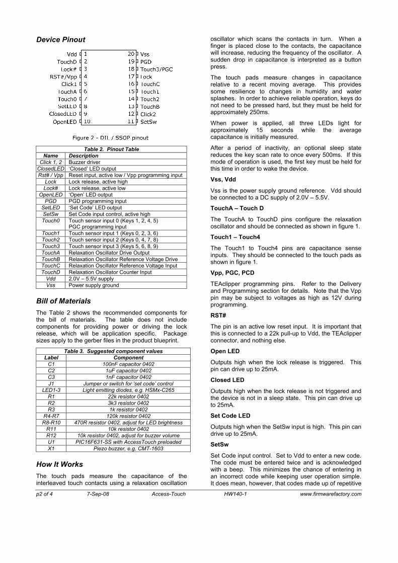
Device Pinout
Table 2. Pinout TableName Description
Click 1, 2 Buzzer driverClosedLED ‘Closed’ LED outputRst# / Vpp Reset input, active low / Vpp programming input
Lock Lock release, active highLock# Lock release, active low
OpenLED ‘Open’ LED outputPGD PGD programming input
SetLED ‘Set Code’ LED outputSetSw Set Code input control, active highTouch0 Touch sensor input 0 (Keys 1, 2, 4, 5)
PGC programming inputTouch1 Touch sensor input 1 (Keys 0, 2, 3, 6)Touch2 Touch sensor input 2 (Keys 0, 4, 7, 8)Touch3 Touch sensor input 3 (Keys 5, 6, 8, 9)TouchA Relaxation Oscillator Drive OutputTouchB Relaxation Oscillator Reference Voltage DriveTouchC Relaxation Oscillator Reference Voltage InputTouchD Relaxation Oscillator Counter Input
Vdd 2.0V – 5.5V supplyVss Power supply ground
Bill of Materials
The Table 2 shows the recommended components for the bill of materials. The table does not include components for providing power or driving the lock release, which will be application specific. Package sizes apply to the gerber files in the product blueprint.
Table 3. Suggested component valuesLabel Component
C1 100nF capacitor 0402C2 1uF capacitor 0402C3 1nF capacitor 0402J1 Jumper or switch for ‘set code’ control
LED1-3 Light emitting diodes, e.g. HSMx-C265R1 22k resistor 0402R2 3k3 resistor 0402R3 1k resistor 0402
R4-R7 120k resistor 0402R8-R10 470R resistor 0402, adjust for LED brightness
R11 10k resistor 0402R12 10k resistor 0402, adjust for buzzer volumeU1 PIC16F631-SS with AccessTouch preloadedX1 Piezo buzzer, e.g. CMT-1603
How It Works
The touch pads measure the capacitance of the interleaved touch contacts using a relaxation oscillation
oscillator which scans the contacts in turn. When a finger is placed close to the contacts, the capacitance will increase, reducing the frequency of the oscillator. A sudden drop in capacitance is interpreted as a button press.
The touch pads measure changes in capacitance relative to a recent moving average. This provides some resilience to changes in humidity and water splashes. In order to achieve reliable operation, keys do not need to be pressed hard, but they must be held for approximately 250ms.
When power is applied, all three LEDs light for approximately 15 seconds while the average capacitance is initially measured.
After a period of inactivity, an optional sleep state reduces the key scan rate to once every 500ms. If this mode of operation is used, the first key must be held for this time in order to wake the device.
Vss, Vdd
Vss is the power supply ground reference. Vdd should be connected to a DC supply of 2.0V – 5.5V.
TouchA – Touch D
The TouchA to TouchD pins configure the relaxation oscillator and should be connected as shown in figure 1.
Touch1 – Touch4
The Touch1 to Touch4 pins are capacitance sense inputs. They should be connected to the touch pads as shown in figure 1.
Vpp, PGC, PCD
TEAclipper programming pins. Refer to the Delivery and Programming section for details. Note that the Vpppin may be subject to voltages as high as 12V during programming.
RST#
The pin is an active low reset input. It is important that this is connected to a 22k pull-up to Vdd, the TEAclipper connector, and nothing else.
Open LED
Outputs high when the lock release is triggered. This pin can drive up to 25mA.
Closed LED
Outputs high when the lock release is not triggered and the device is not in a sleep state. This pin can drive up to 25mA.
Set Code LED
Outputs high when the SetSw input is high. This pin can drive up to 25mA.
SetSw
Set Code input control. Set to Vdd to enter a new code. The code must be entered twice and is acknowledged with a beep. This minimizes the chance of entering in an incorrect code while keeping user operation simple. It does mean, however, that codes made up of repetitive
p3 of 4 7-Sep-08 Access-Touch HW140-1 www.firmwarefactory.com
sequences longer than the minimum code length cannot be specified, e.g. 12341234.
Typically the set switch will only be accessible from inside the secured-access area, or will be implemented as a key switch.
The code set by default is 123.
Lock, Lock#
The lock outputs control the access lock. These pins can drive up to 25mA, sufficient for a small relay.
Click1, Click2
Connect to a buzzer to provide audio feedback:
High note: Button press registeredMedium note: Code setLow note: Lock open
These pins can drive up to 25mA, so a current limiting series resistor may be required. This is the function of R12 in figure 1, which also serves as a volume control.
Touch Pad Design
The touch pads need to be designed for maximum capacitance when a finger is present, and minimum capacitance when not present. The design shown in figure 1 has been shown to be effective, with a track width of 1.1mm and gap of 0.33mm. The overall pad size should be at least 13mm square, with a minimum gap between pads of 5mm.
No physical contact is required and the touch pads may be overlaid with, for example, a label or thin acrylic panel. Alternatively, the pad may be placed in an inner PCB layer immediately below the exposed PCB surface.
Button presses are detected as a rise in capacitance in one or two sense lines. Too high a trigger sensitivity can be just as troublesome as low a trigger sensitivity. Therefore the sensitivity setting may require adjustment to suit a particular physical setup. (See nonvolatile settings section below.)
To avoid ambiguity, it is important that fingers do not induce capacitance where not wanted. Avoid unnecessary routing tracks on the exposed surface of the PCB. Apart from the touch pads, the circuit should avoid being placed where fingers might get close. Avoid metal enclosures.
Non-Volatile Settings
Various settings can be specified in the code memory at programming time (see the Programming AccessTouchsection). Alternatively, they may be set in EEPROM memory at a later date using a PIC programmer. The EEPROM locations are shown in table 4.
Table 4. Nonvolatile Settings In EEPROMAddress Name Default Description
0x00 UseEE 0x00 Zero to use code memory settings, or non-zero for EEPROM settings
0x01 Sens 0x38 Touch trigger sensitivity0x02 OpTime 0x08 Lock open time, 1/3s units0x03 OpBeep 0x01 Zero for no beep on unlock
Table 4. Nonvolatile Settings In EEPROMAddress Name Default Description
0x04 WaitSlp 0x00 Wait time before entering sleep mode, or zero for no sleep, 1/15s units
0x05 MinLen 0x03 Minimum number of digits permitted in a new code.
Note that the access code is also stored in EEROM and is visible to anybody with a PIC programmer.
Firmware Delivery on HexWax
If not bought as a pre-programmed chip, AccessTouch firmware is available as an encrypted firmware download from www.hexwax.com. To download it you will need a TEAclipper/PIC HV and a TEAclipper/USB adapter.
To load the firmware onto the TEAclipper, start the HexWax Explorer firmware and log in. Then download the AccessTouch firmware pack from the hexwax.com products section. When download completes, an AccessTouch folder will appear in the Local Files section of HexWax Explorer. In this folder is the AccessTouch.wax file that contains the firmware.
You will need AccessTouch license credits in order to decrypt the AccessTouch.wax file. Contact hexwax.com for details of payment options and how to obtain free samples.
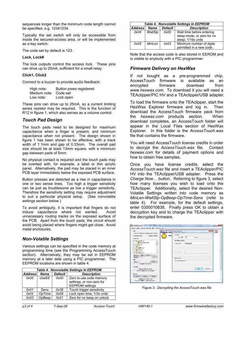
Once you have license credits, select theAccessTouch.wax file and insert a TEAclipper/PIC HV into the TEAclipper/USB adapter. Press the Charge Now… button. Referring to figure 3, select how many licenses you wish to load onto the TEAclipper. Additionally, select the desired Non-Volatile Settings written into code memory as MinLen-WaitSlp-OpBeep-OpTime-Sens (refer to table 4). For example, for the default settings, enter 0300010838. Finally press OK to obtain a decryption key and to charge the TEAclipper with the decrypted firmware.
Figure 3: Decrypting the AccessTouch.wax file

p4 of 4 7-Sep-08 Access-Touch HW140-1 www.firmwarefactory.com
Programming AccessTouch
AccessTouch is programmed into the microcontroller by inserting the TEAclipper into its connector. The circuit must be powered and the TEAclipper must be held in place until the LEDs stop flashing and the green LED glows steadily. The voltage Vdd during programming must be 4.5V – 5.5V.
Since the programming time is very fast, no programming socket is required for the TEAclipper. It may be leaned against five plate-through holes as depicted in figure 4.
1mm hole dia
2.54mm spacingPin 1 indicatedby square pad
PG
D
Touch0
RS
T#
Vss
Vdd
Figure 4. Recommended plate-through connector design
Evaluation Board
An evaluation board is available for AccessTouchconsisting of a pre-assembled board containing all circuitry except the Set switch, lock driver and power source.
Product Blueprint
The evaluation board Gerber files and other construction information are available as a product blueprint in return for a signed Nondisclosure Agreement.
Alternate Options
AccessTouch can be reconfigured for alternate applications. For example:
Combination Safe Controller
Touch sensitive 12-key matrix keyboard replacement
Contact us for more information on these applications.
Author Contact
Firmware Factory Ltd2 Marshall St, 3rd FloorLondon W1F 9BB, [email protected]@firmwarefactory.com