Accessory Fitting Instructions · Accessory Fitting Instructions ... mechanism on the bottom...
14
Accessory Fitting Instructions 1 of 14 Publication part number 9900792 issue 4 © Triumph Designs Ltd. 2017 English Thank you for choosing this Triumph genuine accessory kit. This accessory kit is the product of Triumph's use of proven engineering, exhaustive testing, and continuous striving for superior reliability, safety and performance. Completely read all of these instructions before commencing the installation of the accessory kit in order to become thoroughly familiar with the kit’s features and the installation process. These instructions should be considered a permanent part of your accessory kit, and should remain with it even if your accessory equipped motorcycle is subsequently sold. Top Box Kit - Aluminium Kit Number Models Affected A9500530 Tiger XR, Tiger XRA, Tiger XRX, Tiger XC, Tiger XCA, Tiger XCX, Explorer XR, Explorer XRx, Explorer XRT , Explorer XC, Explorer XCx, Explorer XCA, Tiger 800 XR, Tiger 800 XRX, Tiger 800 XRX LRH, Tiger 800 XCX, Tiger 800 XRT, Tiger 800 XCA, Tiger 1200 XR A9500606 Tiger XR, Tiger XRA, Tiger XRX, Tiger XC, Tiger XCA, Tiger XCX, Explorer XR, Explorer XRx, Explorer XRT , Explorer XC, Explorer XCx, Explorer XCA, Tiger 800 XR, Tiger 800 XRX, Tiger 800 XRX LRH, Tiger 800 XCX, Tiger 800 XRT, Tiger 800 XCA, Tiger 1200 XR A9500810 Tiger 1200 XRX, Tiger 1200 XRX LRH, Tiger 1200 XCX, Tiger 1200 XRT, Tiger 1200 XCA A9500815 Tiger 1200 XRX, Tiger 1200 XRX LRH, Tiger 1200 XCX, Tiger 1200 XRT, Tiger 1200 XCA Sliding Carriage Kit Kit Number Models Affected A2353434 Tiger XR, Tiger XRA, Tiger XRX, Tiger XC, Tiger XCA and Tiger XCX, Tiger 800 XR, Tiger 800 XRX, Tiger 800 XRX LRH, Tiger 800 XCX, Tiger 800 XRT, Tiger 800 XCA A2353440 Explorer XR, Explorer XRx, Explorer XRT , Explorer XC, Explorer XCx, Explorer XCA, Tiger 1200 XR, Tiger 1200 XRX, Tiger 800 XRX LRH, Tiger 1200 XCX, Tiger 1200 XRT, Tiger 1200 XCA
Transcript of Accessory Fitting Instructions · Accessory Fitting Instructions ... mechanism on the bottom...

Accessory Fitting Instructions
1 of 14Publication part number 9900792 issue 4© Triumph Designs Ltd. 2017
English
Thank you for choosing this Triumph genuine accessory kit. This accessory kit is the product of Triumph'suse of proven engineering, exhaustive testing, and continuous striving for superior reliability, safety andperformance.
Completely read all of these instructions before commencing the installation of the accessory kit in order tobecome thoroughly familiar with the kit’s features and the installation process.
These instructions should be considered a permanent part of your accessory kit, and should remain with iteven if your accessory equipped motorcycle is subsequently sold.
Top Box Kit - AluminiumKit Number Models Affected
A9500530 Tiger XR, Tiger XRA, Tiger XRX, Tiger XC, Tiger XCA, Tiger XCX,
Explorer XR, Explorer XRx, Explorer XRT, Explorer XC, Explorer XCx, Explorer XCA,
Tiger 800 XR, Tiger 800 XRX, Tiger 800 XRX LRH, Tiger 800 XCX, Tiger 800 XRT, Tiger 800 XCA,Tiger 1200 XR
A9500606 Tiger XR, Tiger XRA, Tiger XRX, Tiger XC, Tiger XCA, Tiger XCX,
Explorer XR, Explorer XRx, Explorer XRT, Explorer XC, Explorer XCx, Explorer XCA,
Tiger 800 XR, Tiger 800 XRX, Tiger 800 XRX LRH, Tiger 800 XCX, Tiger 800 XRT, Tiger 800 XCA,Tiger 1200 XR
A9500810 Tiger 1200 XRX, Tiger 1200 XRX LRH, Tiger 1200 XCX, Tiger 1200 XRT, Tiger 1200 XCA
A9500815 Tiger 1200 XRX, Tiger 1200 XRX LRH, Tiger 1200 XCX, Tiger 1200 XRT, Tiger 1200 XCA
Sliding Carriage KitKit Number Models Affected
A2353434 Tiger XR, Tiger XRA, Tiger XRX, Tiger XC, Tiger XCA and Tiger XCX,Tiger 800 XR, Tiger 800 XRX, Tiger 800 XRX LRH, Tiger 800 XCX, Tiger 800 XRT, Tiger 800 XCA
A2353440 Explorer XR, Explorer XRx, Explorer XRT, Explorer XC, Explorer XCx, Explorer XCA,
Tiger 1200 XR, Tiger 1200 XRX, Tiger 800 XRX LRH, Tiger 1200 XCX, Tiger 1200 XRT, Tiger 1200 XCA

2 of 14
Parts Supplied: A9500530, A9500606, A9500810, A9500815
1
1. Top box 1 off

3 of 14
Parts Supplied: A2353434
1. Sliding carriage assembly 1 off 4. Bolt, M8 x 20 mm 2 off
2. Mounting bracket 1 off 5. Lock nut, M8 2 off
3. Washer, 6.4 x 18 mm 8 off 6. Omega clip 1 off
2
1
3
4
56

4 of 14
Parts Supplied: A2353440
2
1
3
1. Sliding carriage assembly 1 off 3. Lock nut, M8 4 off
2. Bolt, M8 x 25 mm 4 off
5 of 14
Note:
• Triumph offers a broad range of approvedgenuine accessories for your motorcycle. We cannot therefore cover all possibleequipment variations in these instructions. Forremoval and installation of Triumph GenuineAccessories always refer to the instructionssupplied with the respective accessory kit. To obtain additional copies of any Triumphaccessory instructions, visit www.triumphinstructions.com or contact yourauthorised Triumph dealer.
Note:
• Lock nuts can be reused, providing resistancecan be felt when the locking portion passesover the thread of the bolt or stud.
• Always use the correct replacement lock nut asrecommended in the Triumph parts catalogue.
1. Place the motorcycle on a paddock stand.
2. Remove the rider’s seat as described in theService Manual.
3. Disconnect the battery, negative (black) leadfirst.
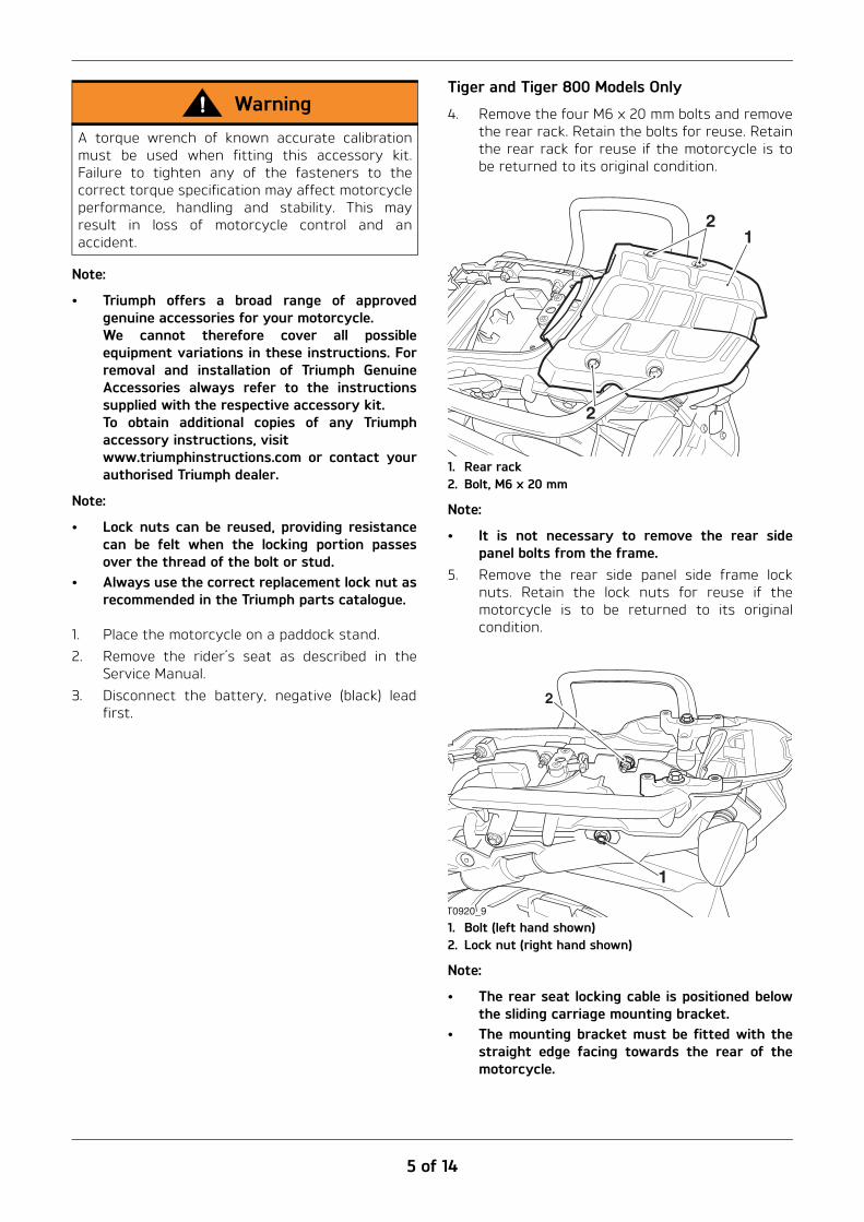
Tiger and Tiger 800 Models Only
4. Remove the four M6 x 20 mm bolts and removethe rear rack. Retain the bolts for reuse. Retainthe rear rack for reuse if the motorcycle is tobe returned to its original condition.
1. Rear rack2. Bolt, M6 x 20 mm
Note:
• It is not necessary to remove the rear sidepanel bolts from the frame.
5. Remove the rear side panel side frame locknuts. Retain the lock nuts for reuse if themotorcycle is to be returned to its originalcondition.
1. Bolt (left hand shown)2. Lock nut (right hand shown)
Note:
• The rear seat locking cable is positioned belowthe sliding carriage mounting bracket.
• The mounting bracket must be fitted with thestraight edge facing towards the rear of themotorcycle.
WarningA torque wrench of known accurate calibrationmust be used when fitting this accessory kit.Failure to tighten any of the fasteners to thecorrect torque specification may affect motorcycleperformance, handling and stability. This mayresult in loss of motorcycle control and anaccident. 1
2
2
1
T0920_9
2

6 of 14
6. Position the mounting bracket from the kit tothe sub frame ensuring the straight edge isfacing to the rear of the motorcycle and takingcare to route the seat lock cable in theorientation shown below.
1. Mounting bracket2. Threaded bracket3. Seat lock cable
7. Secure the mounting bracket using the rearside frame panel bolts. Do not fully tighten thebolts at this stage.
8. Secure the rear seat locking cable using theomega clip from the kit to the hole in thebracket.
1. Mounting bracket2. Omega clip3. Seat lock cable
Note:
• A small amount of grease is required to holdthe washers in their correct position duringinstallation.
9. Collect four washers from the kit. Lightlygrease the lower surface of each washer andposition on the threaded bosses of the grabhandles as shown below.
1. Threaded boss2. Washer
10. Align the sliding carriage to the grab handle asshown below. Use four commercially available4 mm x 100 mm rods to keep the washers inposition while the sliding carriage is beingassembled.
1. Sliding carriage2. Washer3. Rod
2
13
Rear
1
2
3
2
1
21
2
1
3
2
3

7 of 14
11. Position the four remaining washers from thekit and the M6 x 20 mm bolts removedpreviously through the sliding carriage andsecure to the grab handle bosses as shownbelow. Do not fully tighten at this stage.
1. Bolt, M6 x 20 mm2. Washer3. Sliding carriage (left hand side shown)
Note:
• Ensure the washers are not dislodged duringfitment of the sliding carriage to the grabhandle boss.
12. Collect the M8 lock nuts and M8 x 20 mm boltsfrom the kit and secure the sliding carriage tothe mounting bracket, as shown below. Do notfully tighten at this stage.
1. Bolt, M8 x 20 mm2. Sliding carriage
13. Tighten the M6 x 20 mm bolts to 3 Nm, asshown below.
14. Tighten the M8 x 20 mm nuts and bolts to20 Nm, as shown below.
1. Bolt, M6 x 20 mm2. Bolt, M8 x 20 mm
CautionWhen fitting the left hand M8 x 20 mm bolt andnut ensure that the nuts and bolts do notinterfere with the routing of the rear seat releasecable. A trapped or damaged release cable willrender the rear seat lock inoperative.
2
1
3
2
1
2 1

8 of 14
15. Tighten the rear side panel bolts to 20 Nm, asshown below.
1. Bracket2. Rear side panel bolt, M8 x 50 mm
Explorer and Tiger 1200 Models Only
16. Remove the four bolts securing the rear rackcover, discarding the lock nuts. Retain the boltsfor reuse if the motorcycle is to be returned toits original condition.
1. Fixings2. Rear rack cover
17. Align the sliding carriage to the rear rack, fitthe four bolts and lock nuts from the kit andtighten to 20 Nm.
1. Sliding carriage2. Bolts
All Models
18. Reconnect the battery, positive (red lead) first,as described in the Service Manual.
19. Refit the rider’s seat, refer to the ServiceManual.
20. Remove the motorcycle from the paddockstand and place on the side stand.
2
1
1
2
WarningThe sliding carriage must be allowed to move fromside to side on the slide plate. If the slidingcarriage is not free to move from side to sidewhen the top box is fitted, the stability andhandling characteristics of the motorcycle may beaffected, leading to loss of control and anaccident.
WarningIf a load is carried on the sliding carriage withoututilising the top box, it must be securely attachedto the sliding carriage only and not any other partof the rear rack. The sliding carriage must beallowed to move from side to side on the slideplate. If the sliding carriage is not free to movefrom side to side on the slide plate, the stabilityand handling characteristics of the motorcyclemay be affected, leading to the loss of control andan accident.
2
1

9 of 14
Lock Barrel Fitment - A9500530, A9500606
1. Take a lock barrel (supplied with themotorcycle). Align the tumblers to the slot andpush the barrel into position until it clicks intoplace.
1. Slot2. Tumblers
Note:
• The lock barrel will only fit one way.2. Check the operation of the lock barrel.
Lock Barrel Fitment - A9500810, A9500815
1. Fit the ignition key into the lock barrel locksupplied with the motorcycle when new.
2. Turn the ignition key clockwise to remove thelock barrel from its protective case.
1. Ignition key2. Lock barrel3. Protective case
Note:
• The lock barrel will only fit one way.3. Align the tumblers to the slot and push the
barrel into position until it clicks into place.
1. Slot2. Tumblers
Note:
• Once fitted the lock barrel cannot be removed.4. Check the operation of the barrel.
CautionDo not remove the ignition key from the lockbarrel when the lock barrel has been removedfrom its protective case. If the key is removed when the lock barrel hasbeen removed from the protective case the lockbarrel will be in an unstable condition and theinternal components will become unassembledand may be lost which will prevent fitment of thelock barrel.The ignition key must only be removed when thelock barrel has been fitted into the top box.
21
1
3
1
2
21
1
10 of 14
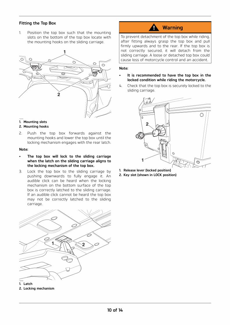
Fitting the Top Box
1. Position the top box such that the mountingslots on the bottom of the top box locate withthe mounting hooks on the sliding carriage.
1. Mounting slots2. Mounting hooks
2. Push the top box forwards against themounting hooks and lower the top box until thelocking mechanism engages with the rear latch.
Note:
• The top box will lock to the sliding carriagewhen the latch on the sliding carriage aligns tothe locking mechanism of the top box.
3. Lock the top box to the sliding carriage bypushing downwards to fully engage it. Anaudible click can be heard when the lockingmechanism on the bottom surface of the topbox is correctly latched to the sliding carriage.If an audible click cannot be heard the top boxmay not be correctly latched to the slidingcarriage.
1. Latch2. Locking mechanism
Note:
• It is recommended to have the top box in thelocked condition while riding the motorcycle.
4. Check that the top box is securely locked to thesliding carriage.
1. Release lever (locked position)2. Key slot (shown in LOCK position)
2
1
21
WarningTo prevent detachment of the top box while riding,after fitting always grasp the top box and pullfirmly upwards and to the rear. If the top box isnot correctly secured, it will detach from thesliding carriage. A loose or detached top box couldcause loss of motorcycle control and an accident.
2
1

11 of 14
Removing the Top Box
5. Insert the key into the lock. Turn the key to theUNLOCK position and lift the release lever.
6. Lift the rear of the top box to release thelocking mechanism from the rear latch. Slidethe top box rearward to disengage the frontmounting hooks and lift the top box away fromthe sliding carriage.
1. Key slot (shown in UNLOCK position)2. Release lever (open position)
Top Box Operation
1. To unlock and open the top box lid, insert thekey and turn it to the UNLOCK position, thenrelease the top box lid latch. The lid can thenbe opened.
1. Key slot (shown in UNLOCK position)2. Locking bar3. Lid latch handle (open position)
2. To lock the lid of the top box, fully close the lid,lock the lid latch handle in position and turnthe key to the LOCK position. Remove the key.
Sliding Carriage Maintenance
Note:
• If for any reason a rubber pad is damaged orbecomes loose, all of the rubber pads must bereplaced at the same time.
1. Install the rubber pads with the contactsurface facing toward the top box as shownbelow.
1. Rubber pads2. Mounting hole
2
1
2
1
3
WarningA top box incorrectly secured with the rubberpads damaged or missing may detach resulting ina dangerous riding condition. Before riding, alwaysensure that the top box is mounted correctly.Ensure the rubber pads are secure and notdamaged in any way.
2
1

12 of 14
Replacement Tyres
Note:
• A list of approved tyres specific to thesemodels is available from your authorisedTriumph dealer, or on the internet atwww.triumph.co.uk.
T
T
WarningUse the recommended tyres ONLY in thecombinations given. Do not mix tyres fromdifferent manufacturers or mix differentspecification tyres from the same manufacturersas this may result in loss of motorcycle controland an accident.
WarningAn incorrectly mounted top box may detach whilstriding, resulting in a dangerous riding condition.
Before riding, always ensure that the top box ismounted correctly. Ensure that the lock barrel isturned to the LOCK position and the key removed.
1. Top box2. Lock position
A top box that detaches whilst riding may causeloss of motorcycle control and an accident and/orinjury to other road users.
T2102
2
1
WarningThe maximum safe load for the top box is 5 kg(11 lbs). Never exceed this loading limit as this maycause the motorcycle to become unstable leadingto loss of motorcycle control and an accident.
WarningAfter fitting or removing the top box, operate themotorcycle in a safe area free from traffic to gainfamiliarity with the new handling characteristics.Operation when not familiar with the newcharacteristics of the motorcycle may result inloss of motorcycle control and an accident.
WarningIncorrect loading may result in an unsafe ridingcondition leading to loss of motorcycle control andan accident.
Always ensure any loads carried are evenlydistributed on both sides of the motorcycle.Ensure that the load is correctly secured suchthat it will not move around while the motorcycleis in motion.
Evenly distribute the load within each pannier.Pack heavy items at the bottom and on theinboard side of the pannier.
Always check the load security regularly (thoughnot while the motorcycle is in motion) and ensurethat the load does not extend beyond the rear ofthe motorcycle. Never exceed the maximumvehicle loading weight. Refer to the Owner’sHandbook for the maximum loading weightspecification.
This maximum loading weight is made up from thecombined weight of the rider, passenger, anyaccessories fitted and any load carried.
For models that have adjustable suspensionsettings, ensure that front and rear springpreload and damping settings are suitable for theloading condition of the motorcycle. Refer to theOwner’s Handbook.
Note the maximum permissible payload for thepanniers is stated on a label inside the pannier.

13 of 14
Cleaning the Luggage System
All parts of the luggage system fitted to yourmotorcycle must be cleaned regularly to avoiddeterioration of their appearance.
WashingPrepare a mixture of cold water and mildautomotive cleaner. Do not use a highly alkalinesoap as commonly found at commercial car washesbecause it leaves a residue.
Wash the luggage system with a soft cloth. Do notuse an abrasive scouring pad or steel wool. They willdamage the finish.
Rinse the luggage system thoroughly.
Ensure no soap or water enters the insidecompartment.
Dry the luggage system as far as possible with asoft cloth.
ProtectingWhen the luggage system is dry, protect with acolourless lubricating spray.
It is recommended that regular protection beapplied to the system as this will both protect andenhance the system's appearance.
Note:
• It is recommended to use the Triumph innerbags to protect both the luggage contents andthe inner surfaces of the luggage.
CautionThe use of abrasive cleaners and polishes willdamage the system and must not be used.
WarningIf, after fitment of this accessory kit, you have anydoubt about the performance of any aspect of themotorcycle, contact an authorised Triumph dealerand do not ride the motorcycle until theauthorised dealer has declared it fit for use. Ridinga motorcycle when there is any doubt as to anyaspect of the performance of the motorcycle mayresult in loss of control of the motorcycle leadingto an accident.
WarningThis motorcycle must not be operated above thelegal road speed limit except in authorisedclosed-course conditions.
WarningOnly operate this Triumph motorcycle at highspeed in closed-course, on-road competition or onclosed-course racetracks. High-speed operationshould only be attempted by riders who have beeninstructed in the techniques necessary forhigh-speed riding and are familiar with themotorcycle's characteristics in all conditions.
High-speed operation in any other circumstancesis dangerous and will lead to loss of motorcyclecontrol and an accident.

14 of 14
WarningNever ride an accessory-equipped motorcycle, or amotorcycle carrying a payload of any kind, atspeeds above 80 mph (130 km/h). In either/both ofthese conditions, speeds in excess of 80 mph(130 km/h) should not be attempted even wherethe legal speed limit permits this.
The presence of accessories and/or payload willcause changes in the stability and handling of themotorcycle.
Failure to allow for changes in motorcycle stabilitymay lead to loss of motorcycle control or anaccident.
When riding at high speed, always be aware thatvarious motorcycle configuration and environ-mental factors can adversely affect the stability ofyour motorcycle. For example:
• Incorrectly balanced loads on both sides ofthe motorcycle.
• Incorrectly adjusted front and rearsuspension settings.
• Incorrectly adjusted tyre pressures.
• Excessively or unevenly worn tyres.
• Side winds and turbulence from other vehicles.
• Loose clothing.
Remember that the 80 mph (130 km/h) absolutelimit will reduce by the fitting of non-approvedaccessories, incorrect loading, worn tyres, overallmotorcycle condition and poor road or weatherconditions.
WarningNever ride an accessory equipped motorcycle atspeeds above 80 mph (130 km/h).
The presence of accessories will cause changes inthe stability and handling of the motorcycle.Failure to allow for changes in motorcycle stabilitymay lead to loss of control or an accident.
Remember that the 80 mph (130 km/h) limit will bereduced by the fitting of non-approvedaccessories, incorrect loading, worn tyres, overallmotorcycle condition and poor road or weatherconditions.