Access Systems Manual (rev 7) (5-23-17)
15
Hydraulic Access Systems Operation and Maintenance Manual Metal Samples Company A Division of Alabama Specialty Products, Inc. 152 Metal Samples Rd., Munford, AL 36268 Phone: (256) 358-4202 Fax: (256) 358-4515 E-mail: [email protected] Internet: www.metalsamples.com Houston Office: 6327 Teal Mist Lane, Fulshear, TX 77441 Phone: (832) 451-6825
Transcript of Access Systems Manual (rev 7) (5-23-17)
HydraulicAccess Systems
Operation and Maintenance Manual
Metal Samples Company A Division of Alabama Specialty Products, Inc.
152 Metal Samples Rd., Munford, AL 36268 Phone: (256) 358-4202 Fax: (256) 358-4515 E-mail: [email protected] Internet: www.metalsamples.com
Houston Office: 6327 Teal Mist Lane, Fulshear, TX 77441 Phone: (832) 451-6825

Table of Contents
System Overview ...................................................................................................................1
Safety Precautions .................................................................................................................2
Access Fitting Body Types ......................................................................................................3
Tee Type & Non‐Tee Types ....................................................................................................5
Attaching the Access Fitting Body..........................................................................................6
Plug Assemblies......................................................................................................................7
Solid Plugs ..............................................................................................................................8
Hollow Plugs ...........................................................................................................................9
Installing & Orienting the Plug ...............................................................................................10
Protective Covers ...................................................................................................................11
Cover Installation & Removal ................................................................................................12
Maintenance Procedure for High Pressure Access Systems .................................................13

1
Hydraulic Access Systems
System Overview
Hydraulic Access Systems are specialized piping arrangements which permit internal access to production plant vessels and pipework operating under full process conditions. The corrosion monitoring industry standard for such access systems is based on a 2‐inch nominal bore design.
When operated with the Metal Samples Hydraulic Retrieval Tool and 6000 PSI Hydraulic Service Valve, the hydraulic access systems allow the installation and retrieval of corrosion monitoring coupon holders, probes, chemical injection equipment, and other devices to be carried out on pressurized lines safely and without plant shutdown, at working pressures up to 6,000 psi.
Hydraulic access systems are used most frequently (although not exclusively) in oil and gas production operations. This is typical of high pressure operations in which users are not prepared to shut down and depressurize process systems in order to remove or install corrosion monitoring devices.
The Access Fitting Assembly consists of three main components:
1. Protective Cover – designed to maintain positive force on the Plug, as well as to protect the external threads of the Access Fitting Body. Pressure Retaining Covers also act as a secondary process containment, and include a Bleed Valve and a Pressure Gauge.
2. Plug – the carrier for the installed device. Depending on the type of device being used, a solid plug or a hollow plug is selected. The plug assembly is inserted into the access fitting body and seals the bore of the fitting to contain line pressure.
3. Access Fitting Body – the specialized pipe fitting which is permanently attached to the process plant vessel or pipework.
Safety Precautions 1. Good engineering and operational practices should be adhered to at all times. This manual is a basis
for safe operation. However, it is the responsibility of the user to ensure that they are properly trained and familiar with the product and other work environment precautions that should be taken prior to use.
2. If this is the first time you have used the equipment or you are an infrequent user, you should review the manual and, if possible, perform a trial operation on a mock fitting / trainer.
3. In addition to the requirements of this manual, all plant safety requirements and environmental regulations must be followed.
4. All replacement parts and components should be ordered from Metal Samples to ensure proper fit and performance. Improper fit, performance, or operation can lead to serious injury or in some cases death. Substitutions from any other companies will void any type of warranty.
5. When in doubt, question it. If there are questions or concerns regarding operation or any other instructions, please feel free to contact Metal Samples.
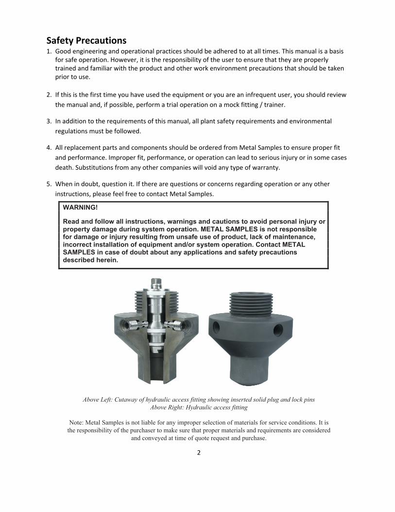
Above Left: Cutaway of hydraulic access fitting showing inserted solid plug and lock pins Above Right: Hydraulic access fitting
Note: Metal Samples is not liable for any improper selection of materials for service conditions. It is the responsibility of the purchaser to make sure that proper materials and requirements are considered
and conveyed at time of quote request and purchase.
2
3
Access Fitting Body
Access Fitting Body Types
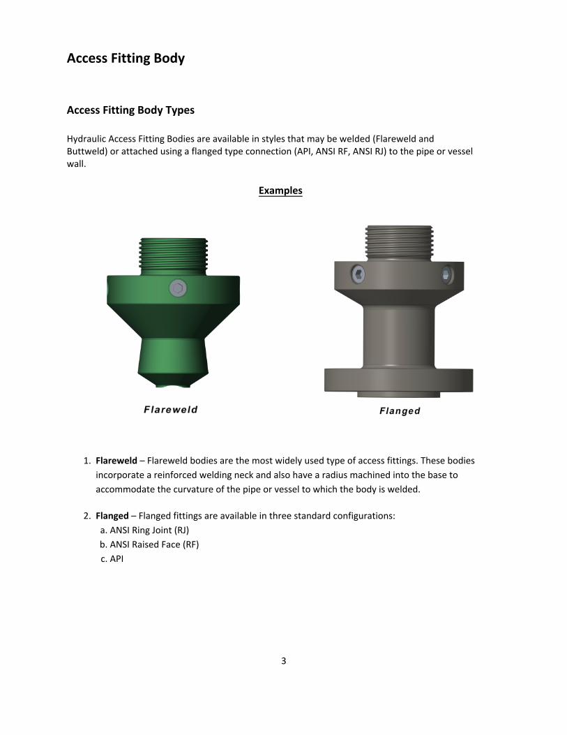
Hydraulic Access Fitting Bodies are available in styles that may be welded (Flareweld and Buttweld) or attached using a flanged type connection (API, ANSI RF, ANSI RJ) to the pipe or vessel wall.
1. Flareweld – Flareweld bodies are the most widely used type of access fittings. These bodies incorporate a reinforced welding neck and also have a radius machined into the base to accommodate the curvature of the pipe or vessel to which the body is welded.
2. Flanged – Flanged fittings are available in three standard configurations:a. ANSI Ring Joint (RJ)b. ANSI Raised Face (RF)c. API
Examples

4
Hydraulic access fittings are manufactured from materials which conform to NACE MR‐0175 specifications for sour service. Choice of material for the access fitting body is based on minimum operating temperature as well as process stream corrosivity. "Standard" temperature materials are suitable for use above a minimum operating temperature of ‐20°F (‐29°C). "Low Temperature" materials should be selected for minimum operating temperatures below this value.
The Metal Samples standard material specification for Flareweld and Buttweld bodies is AISI 1018 for standard temperature and ASTM A350LF2 for low temperature. For flanged fittings, ASTM A105 is used for standard temperature and ASTM A350LF2 for low temperature. However, all access fitting components can be made to order in many other customer‐specified material. Carbon or stainless steel, duplex materials, or other more exotic alloys may be ordered (however, some alloys may have an effect on the pressure/temperature rating).
All hydraulic access fitting bodies have an external 3‐inch ACME thread, which is used to attach the service valve during retrieval/installation operations. Access fitting bodies should always be used with a cover, which acts as a main method of retaining a plug in place. This is also designed to protect both external threads and the service valve sealing surfaces.

5
Tee Type & Non‐Tee Types
Access Fitting Bodies are available as either non‐tee types or tee types.
Non‐tee access fitting bodies are used in applications such as coupon holders and monitoring probes.
Tee type access fitting bodies are used in applications where inlet or outlet access to the process stream is required.
Tee type access fitting bodies are used with Chemical Injection Systems, Sampling, and Sand Monitoring Systems.
The materials of construction of tee type access fitting bodies are the same as the non‐tee type access fitting bodies.
6
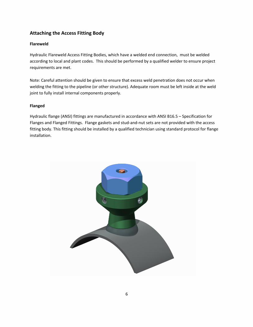
Attaching the Access Fitting Body
Flareweld
Hydraulic Flareweld Access Fitting Bodies, which have a welded end connection, must be welded according to local and plant codes. This should be performed by a qualified welder to ensure project requirements are met.
Note: Careful attention should be given to ensure that excess weld penetration does not occur when welding the fitting to the pipeline (or other structure). Adequate room must be left inside at the weld joint to fully install internal components properly.
Flanged
Hydraulic flange (ANSI) fittings are manufactured in accordance with ANSI B16.5 – Specification for Flanges and Flanged Fittings. Flange gaskets and stud‐and‐nut sets are not provided with the access fitting body. This fitting should be installed by a qualified technician using standard protocol for flange installation.

7
Plug Assemblies
The Plug Assembly is the retrievable carrier which holds corrosion monitoring, chemical injection, or various other devices that may be installed through the access fitting. There are two distinct types of plug assemblies ‐ the Solid Plug and the Hollow Plug.
The plug assembly is inserted into the bore of the access fitting body and is designed to seal against the fitting to act as a barrier against line pressure.
When the plug assembly is used with a tee type access fitting, a valve or flange blank/blind flange must be used with the tee to seal off line pressure.
The standard material of construction for the plug assembly is 316 Stainless Steel (as shown on the following two pages). However, several other material options are available upon request. Please note that some alloys may have an effect on the pressure/temperature rating.
All plug assemblies are individually pressure tested at the factory and are rated for operation at 6000 psi. The operating temperature range for standard plug assemblies is ‐50°F (‐45°C) to 350°F (176°C), but this range can be extended by use of alternative sealing materials.

8
Solid Plugs
Solid plugs carry coupon holders, injection/sampling systems, sand probes, and bio-probes.
The solid plug nut is unscrewed from the base of the plug and replaced by the device being installed. A left‐hand thread and a set screw is used to ensure that installed devices do not become loose during the retrieval procedure.
Notes:
Pipe Plug – Protects internal threads. This must be removed during retrieval operations.
Solid Plug Nut – Only used when no other device is attached.

9
Hollow Plugs
Hollow plugs are used with electrical resistance probes, linear polarization resistance probes, and hydrogen probes.
To connect these devices, the hollow plug seal nut is removed and the monitoring device is screwed into the female thread in the base of the hollow plug. A left‐hand thread is used. Access is allowed through the top of the hollow plug. This allows for electrical connections to be made directly to the probes for taking readings.
Notes:Pipe Plug – Protects internal threads and seals the upper portion of the bore when an adapter is not in use. Must be removed during retrieval operations.
Bore Seal Nut – Only used when no other device is attached.

10
Installing & Orienting the Plug
If the corrosion monitoring device requires alignment with the product flow (coupon holder, LP probe, injection quill, etc.), you will need to assemble the plug with the device to be attached and “reference” or “index” the plug assembly by lightly filing a mark across the top of the plug. The mark should be filed so that the device can be aligned with the product flow.
Prior to inserting the plug assembly, ensure that the hydraulic lock pins are in the fitting and the heads of the pins are retracted flush with the outside diameter of the fitting. Do not fully remove pins during installation.
If inserting the plug under pressure, use the Hydraulic Retriever Tool and 6000 PSI Hydraulic Service Valve.
If inserting the plug manually, insert the plug assembly into the access fitting body taking care to line up the indexing/reference notch as closely as possible with the orientation desired. When inserting the plug, the top of the plug should rest a little above the the top of the fitting (as shown in the picture on page 2).
If minor adjustments are still necessary, turn the plug assembly until the mark aligns to the flow direction.
Installing Hydraulic Lock Pins
¢ƘŜ LJƛƴǎ Ƴdzǎǘ ōŜ ǘƛƎƘǘŜƴŜŘ ŜǾŜƴƭȅ ŀNJƻdzƴŘ ǘƘŜ ŀŎŎŜǎǎ ŦƛǘǘƛƴƎ ƛƴ ƻNJŘŜNJ ǘƻ ŀǾƻƛŘ pushing the plug ŀƎŀƛƴǎǘ ƻƴŜ ǎƛŘŜ ƻŦ ǘƘŜ ŦƛǘǘƛƴƎΦ ¢ƘŜNJŜŦƻNJŜΣ ǎŎNJŜǿ ƛƴ ŀƭƭ LJƛƴǎ dzƴǘƛƭ ǘƘŜy ǘƻdzŎƘ ǘƘŜ LJƭdzƎΦ ¢ƘŜƴ ǘƛƎƘǘŜƴ ƻƴŜ ōȅ ƻƴŜ όŀǎ ǎƘƻǿƴ ƛƴ ǘƘŜ ŎȅŎƭŜ ŘƛŀƎNJŀƳ ōŜƭƻǿύ ŀLJLJNJƻȄƛƳŀǘŜƭȅ мκп ƻŦ ŀ ǘdzNJƴΣ ŀƴŘ NJŜLJŜŀǘ dzƴǘƛƭ ŀƭƭ ƭƻŎƪƛƴƎ LJƛƴǎ ŀNJŜ ǎdzŦŦƛŎƛŜƴǘƭȅ ǘƛƎƘǘŜƴŜŘΦ 9ȄLJŜŎǘ ŀ ǘƻǘŀƭ ƻŦ оπп ǘdzNJƴǎ ŦƻNJ ŀdequate tightening.
If the lock pins suddenly stop after only 1-3 turns, or they can easily be screwed all the way in (4-5 turns) without any resistance, this indicates that the plug is not quite in position. Loosen all pins, retrieve the plug and monitoring equipment attached, and look for damages that might prevent proper installation. If line is pressurized, additional precautions must be taken including (but not limited to) the use of the Metal Samples Hydraulic Retriever and 6000 PSI Hydraulic Service Valve.
O-ringsLocking Pin
Cycle for Tightening of Locking Pins (General Diagram)
1
2
4
3
11
Protective Covers
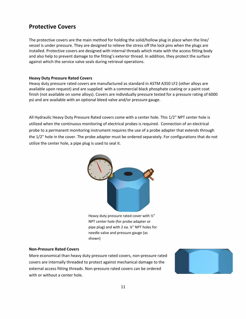
The protective covers are the main method for holding the solid/hollow plug in place when the line/vessel is under pressure. They are designed to relieve the stress off the lock pins when the plugs are installed. Protective covers are designed with internal threads which mate with the access fitting body and also help to prevent damage to the fitting’s exterior thread. In addition, they protect the surface against which the service valve seals during retrieval operations.
Heavy Duty Pressure Rated Covers Heavy duty pressure rated covers are manufactured as standard in ASTM A350 LF2 (other alloys are available upon request) and are supplied with a commercial black phosphate coating or a paint coat finish (not available on some alloys). Covers are individually pressure tested for a pressure rating of 6000 psi and are available with an optional bleed valve and/or pressure gauge.
All Hydraulic Heavy Duty Pressure Rated covers come with a center hole. This 1/2" NPT center hole is utilized when the continuous monitoring of electrical probes is required. Connection of an electrical probe to a permanent monitoring instrument requires the use of a probe adapter that extends through the 1/2" hole in the cover. The probe adapter must be ordered separately. For configurations that do not utilize the center hole, a pipe plug is used to seal it.
Non‐Pressure Rated Covers
More economical than heavy duty pressure rated covers, non‐pressure rated covers are internally threaded to protect against mechanical damage to the external access fitting threads. Non‐pressure rated covers can be ordered with or without a center hole.
Heavy duty pressure rated cover with ½” NPT center hole (for probe adapter or pipe plug) and with 2 ea. ¼” NPT holes for needle valve and pressure gauge (as shown)

12
Cover Installation & Removal
All pressure retaining covers are supplied with an internal o‐ring. Ensure that the o‐ring is installed into the internal groove. Ensure the external threads on the access fitting body are clean and dry. Lubricate the threads with an appropriate grease, and thread the cover onto the fitting. Screw the Cover onto the Access Fitting by hand until it stops. Using a suitable wrench, tighten the cover, but do not over tighten. When properly tightened and under normal operating conditions, the cover should take the load off the lock pins. At this point, the lock pins should or may feel as if they are not fully tightened. Re-tighten the lock pins, but only enough to take up any slack. To remove the cover, first ensure that the lock pins are fully tightened in place. If a pressure retaining cover is used, ensure all pressure is bled from the cover before removal. For pressure rated covers with a pressure gauge attachment, the gauge may be utilized to check for any internal pressures on the cover. The bleed valve can be used to bleed this pressure. If pressure rebuilds, the plug and lock pins should be checked to ensure that they are properly tightened. If it is still not possible to bleed the pressure, the cover should not be removed until the line is depressurized. If the pressure has been successfully bled from the cover, then proceed with unscrewing the cover from the fitting.

13
Maintenance Procedure for High Pressure Access Systems
мΦ High Pressure Plugs – Leak Maintenance
If the high pressure solid/hollow plugs are leaking: remove the plug, replace the primary and secondary seals to prevent further leaks. If this does not solve the issue, please contact Metal Samples for support.
нΦ External Corrosion of Access Fittings (Mainly Applies to Carbon Steels)
If the coating of an installed access fitting is damaged or not sufficiently covering the fitting, re‐apply coating to ensure that external corrosion does not occur. If coating is removed and external corrosion has occurred, grit blast the fitting and re‐apply coating.
оΦ Access Fitting Cover – Thread Maintenance
If it is difficult to install or remove the cover from the access fitting, re‐apply lubricant/grease to ensure smooth threading of the cover back onto the access fitting. If this does not solve the problem, please contact Metal Samples for support.
пΦ If there are questions or concerns regarding operation or any other instructions, please feel free to contact us. A Metal Samples technician or sales rep can be reached in one or more of the following ways:
ŀΦ Phone: (256) 358-4202
ōΦ E-mail: [email protected]