AC3 Installation Manual - Ascon Tecnologic · AC3 - Installation Manual vi General warnings DANGER!...
40
AC 3 System Installation Manual Installation Manual M.I. AC3-1a/15.01 Code: ISTR-MI AC3ENG01a
-
Upload
truongtuong -
Category
Documents
-
view
227 -
download
0
Transcript of AC3 Installation Manual - Ascon Tecnologic · AC3 - Installation Manual vi General warnings DANGER!...

AC3 SystemInstallation ManualInstallation ManualM.I. AC3-1a/15.01
Code: ISTR-MI AC3ENG01a

Copyright ©, 2014 Ascon Tecnologic S.r.l.
All rights reserved
No part of this document may be stored in a retrieval system, or transmitted in any form, electronic or mechanical, without prior written permission of Ascon Tecnologic S.r.l..
Ascon Tecnologic has used the best care and effort in preparing this manual and believes that the information contained in this publication is accurate.As Ascon Tecnologic continues to improve and develop products, the information contained in this manual may also be subject to change. Ascon Tecnologic reserves the right to change such information without notice.Ascon Tecnologic makes no warranty of any kind, expressed or implied, with regard to the documentation contained in this manual.Ascon Tecnologic shall not be liable in any event - technical and publishing error or omissions - for any incidental and consequential damages, in connection with, or arising out of the use of this manual.
sigmadue®, gammadue® and deltadue®, are trademarks of Ascon Tecnologic Srl.
All other trade names or product names are trademarks or registered trademarks.
Ascon Tecnologic srlHeadquarters: viale Indipendenza 56,
27029 Vigevano (PV)Phone: +39 0381 69871Fax: +39 0381 698730Internet Site: www.ascontecnologic.com
E-mail address: [email protected]
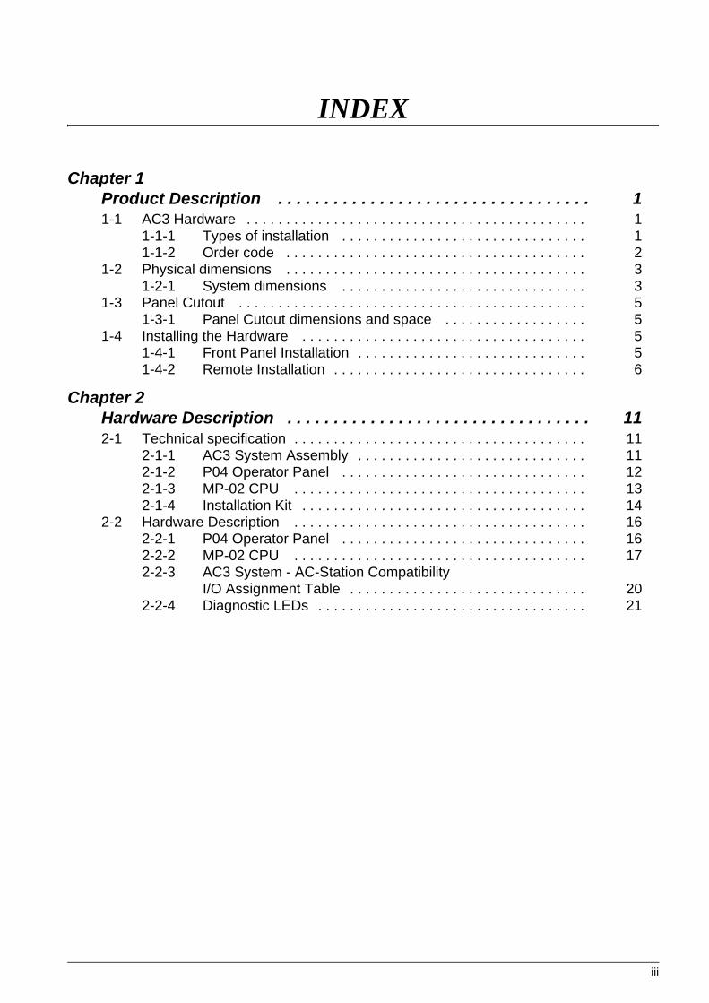
INDEX
iii
Chapter 1 Product Description . . . . . . . . . . . . . . . . . . . . . . . . . . . . . . . . . . 11-1 AC3 Hardware . . . . . . . . . . . . . . . . . . . . . . . . . . . . . . . . . . . . . . . . . . . 1
1-1-1 Types of installation . . . . . . . . . . . . . . . . . . . . . . . . . . . . . . . 11-1-2 Order code . . . . . . . . . . . . . . . . . . . . . . . . . . . . . . . . . . . . . . 2
1-2 Physical dimensions . . . . . . . . . . . . . . . . . . . . . . . . . . . . . . . . . . . . . . 31-2-1 System dimensions . . . . . . . . . . . . . . . . . . . . . . . . . . . . . . . 3
1-3 Panel Cutout . . . . . . . . . . . . . . . . . . . . . . . . . . . . . . . . . . . . . . . . . . . . 51-3-1 Panel Cutout dimensions and space . . . . . . . . . . . . . . . . . . 5
1-4 Installing the Hardware . . . . . . . . . . . . . . . . . . . . . . . . . . . . . . . . . . . . 51-4-1 Front Panel Installation . . . . . . . . . . . . . . . . . . . . . . . . . . . . . 51-4-2 Remote Installation . . . . . . . . . . . . . . . . . . . . . . . . . . . . . . . . 6
Chapter 2 Hardware Description . . . . . . . . . . . . . . . . . . . . . . . . . . . . . . . . . 112-1 Technical specification . . . . . . . . . . . . . . . . . . . . . . . . . . . . . . . . . . . . . 11
2-1-1 AC3 System Assembly . . . . . . . . . . . . . . . . . . . . . . . . . . . . . 112-1-2 P04 Operator Panel . . . . . . . . . . . . . . . . . . . . . . . . . . . . . . . 122-1-3 MP-02 CPU . . . . . . . . . . . . . . . . . . . . . . . . . . . . . . . . . . . . . 132-1-4 Installation Kit . . . . . . . . . . . . . . . . . . . . . . . . . . . . . . . . . . . . 14
2-2 Hardware Description . . . . . . . . . . . . . . . . . . . . . . . . . . . . . . . . . . . . . 162-2-1 P04 Operator Panel . . . . . . . . . . . . . . . . . . . . . . . . . . . . . . . 162-2-2 MP-02 CPU . . . . . . . . . . . . . . . . . . . . . . . . . . . . . . . . . . . . . 172-2-3 AC3 System - AC-Station Compatibility
I/O Assignment Table . . . . . . . . . . . . . . . . . . . . . . . . . . . . . . 202-2-4 Diagnostic LEDs . . . . . . . . . . . . . . . . . . . . . . . . . . . . . . . . . . 21
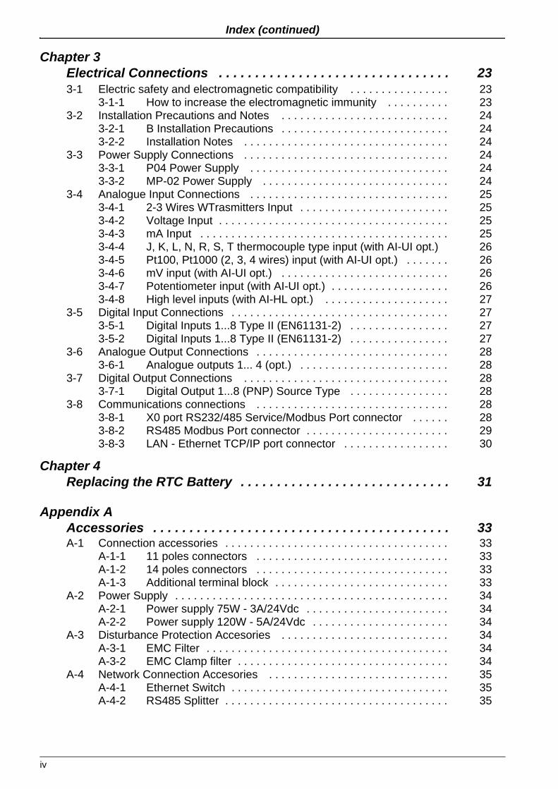
Index (continued)
iv
Chapter 3 Electrical Connections . . . . . . . . . . . . . . . . . . . . . . . . . . . . . . . . 233-1 Electric safety and electromagnetic compatibility . . . . . . . . . . . . . . . . 23
3-1-1 How to increase the electromagnetic immunity . . . . . . . . . . 233-2 Installation Precautions and Notes . . . . . . . . . . . . . . . . . . . . . . . . . . . 24
3-2-1 B Installation Precautions . . . . . . . . . . . . . . . . . . . . . . . . . . . 243-2-2 Installation Notes . . . . . . . . . . . . . . . . . . . . . . . . . . . . . . . . . 24
3-3 Power Supply Connections . . . . . . . . . . . . . . . . . . . . . . . . . . . . . . . . . 243-3-1 P04 Power Supply . . . . . . . . . . . . . . . . . . . . . . . . . . . . . . . . 243-3-2 MP-02 Power Supply . . . . . . . . . . . . . . . . . . . . . . . . . . . . . . 24
3-4 Analogue Input Connections . . . . . . . . . . . . . . . . . . . . . . . . . . . . . . . . 253-4-1 2-3 Wires WTrasmitters Input . . . . . . . . . . . . . . . . . . . . . . . . 253-4-2 Voltage Input . . . . . . . . . . . . . . . . . . . . . . . . . . . . . . . . . . . . . 253-4-3 mA Input . . . . . . . . . . . . . . . . . . . . . . . . . . . . . . . . . . . . . . . . 253-4-4 J, K, L, N, R, S, T thermocouple type input (with AI-UI opt.) 263-4-5 Pt100, Pt1000 (2, 3, 4 wires) input (with AI-UI opt.) . . . . . . . 263-4-6 mV input (with AI-UI opt.) . . . . . . . . . . . . . . . . . . . . . . . . . . . 263-4-7 Potentiometer input (with AI-UI opt.) . . . . . . . . . . . . . . . . . . . 263-4-8 High level inputs (with AI-HL opt.) . . . . . . . . . . . . . . . . . . . . 27
3-5 Digital Input Connections . . . . . . . . . . . . . . . . . . . . . . . . . . . . . . . . . . . 273-5-1 Digital Inputs 1...8 Type II (EN61131-2) . . . . . . . . . . . . . . . . 273-5-2 Digital Inputs 1...8 Type II (EN61131-2) . . . . . . . . . . . . . . . . 27
3-6 Analogue Output Connections . . . . . . . . . . . . . . . . . . . . . . . . . . . . . . . 283-6-1 Analogue outputs 1... 4 (opt.) . . . . . . . . . . . . . . . . . . . . . . . . 28
3-7 Digital Output Connections . . . . . . . . . . . . . . . . . . . . . . . . . . . . . . . . . 283-7-1 Digital Output 1...8 (PNP) Source Type . . . . . . . . . . . . . . . . 28
3-8 Communications connections . . . . . . . . . . . . . . . . . . . . . . . . . . . . . . . 283-8-1 X0 port RS232/485 Service/Modbus Port connector . . . . . . 283-8-2 RS485 Modbus Port connector . . . . . . . . . . . . . . . . . . . . . . . 293-8-3 LAN - Ethernet TCP/IP port connector . . . . . . . . . . . . . . . . . 30
Chapter 4 Replacing the RTC Battery . . . . . . . . . . . . . . . . . . . . . . . . . . . . . 31
Appendix A Accessories . . . . . . . . . . . . . . . . . . . . . . . . . . . . . . . . . . . . . . . . . 33A-1 Connection accessories . . . . . . . . . . . . . . . . . . . . . . . . . . . . . . . . . . . . 33
A-1-1 11 poles connectors . . . . . . . . . . . . . . . . . . . . . . . . . . . . . . . 33A-1-2 14 poles connectors . . . . . . . . . . . . . . . . . . . . . . . . . . . . . . . 33A-1-3 Additional terminal block . . . . . . . . . . . . . . . . . . . . . . . . . . . . 33
A-2 Power Supply . . . . . . . . . . . . . . . . . . . . . . . . . . . . . . . . . . . . . . . . . . . . 34A-2-1 Power supply 75W - 3A/24Vdc . . . . . . . . . . . . . . . . . . . . . . . 34A-2-2 Power supply 120W - 5A/24Vdc . . . . . . . . . . . . . . . . . . . . . . 34
A-3 Disturbance Protection Accesories . . . . . . . . . . . . . . . . . . . . . . . . . . . 34A-3-1 EMC Filter . . . . . . . . . . . . . . . . . . . . . . . . . . . . . . . . . . . . . . . 34A-3-2 EMC Clamp filter . . . . . . . . . . . . . . . . . . . . . . . . . . . . . . . . . . 34
A-4 Network Connection Accesories . . . . . . . . . . . . . . . . . . . . . . . . . . . . . 35A-4-1 Ethernet Switch . . . . . . . . . . . . . . . . . . . . . . . . . . . . . . . . . . . 35A-4-2 RS485 Splitter . . . . . . . . . . . . . . . . . . . . . . . . . . . . . . . . . . . . 35

v
Preface
The products described in this manual should be installed, operated and maintained only by qualified personnel who is familiar with automation safety topics and applicable national standards.
Using this manual
Specifications within the text of this manual are given in the International System of Units (SI), with non SI equivalents in parentheses.
Fully Capitalized words within the text indicate markings found on the equipment.
Words in bold style within the text indicate markings found in the Configuration Tools.
Warnings, Cautions and Notes are used to emphasize critical instructions:
� DANGER! Indicates an imminently hazardous situation which, if not avoided, will result in death or seri-ous injury.
� WARNING Indicates a potentially hazardous situation which, if not avoided, could result in death or seri-ous injury.
� Caution Indicates a potentially hazardous situation which, if not avoided, may result in minor or mod-erate injury, or property damage.
Note: Highlights important information about an operating procedure or the equipment.

AC3 - Installation Manual
vi
General warnings
� DANGER! Whenever a failure or a malfunction of the device may cause dangerous situations for per-sons, things or animals, please remember that the plant must be equipped with additional devices which will guarantee safety.
� WARNING We warrant that the products will be free from defects in material and workmanship for 18 months from the date of delivery. Products and components that are subject to wear due to conditions of use, service life and misuse are not covered by this warranty.
Current Documentation on the Internet
Make sure you are always working with the latest version of this document.
Ascon Tecnologic S.r.l. reserves the right to make changes to its products in the name of technological advancement.
New manual revisions, when published, and can be found online at:
http://www.ascontecnologic.com

1
Chapter 1 Product Description
1-1 AC3 Hardware
The AC3 system has been specifically projected to substitute the AC Station controller, but can also be used as a normal Multiloop control system.
The main components of an AC3 system are:
• P04 Operator Panel;
• MP-02 CPU;
• An Ethernet cable to connect the CPU to the Operator Panel;
• Mounting kit (a plastic adapter to install the P04 into the cutout made for the AC-Station, a metal plate to mount the CPU MP-02 and two metal clamps to fit the structure to the front panel of the cabinet).
Additional (optional) components of the AC3 system:
• Up to two expansion modules also in a mixed configuration of:- MP-D1/08-08 module coming with 8 Digital Inputs and 8 Digital Outputs;- MP-D1/16-16 module coming with 16 Digital Inputs and 16 Digital Outputs;- MP-D2/08-08 module coming with 8 Digital Inputs and 8 Relay Outputs;- MP-D4/08-08 module coming with 8 High Level (120 VAC) Digital Inputs
and 8 Relay Outputs.
• Optional accessories:- 24 Vdc 5 A Power supply (APS2ALDR12024);- 6 ports 10/100/1000 Ethernet Switch (APS2ATOPEH2306);- RS485 splitter with RJ45 connectors (APS2LOCALBUSDUPLEX).
1-1-1 Types of installationThere are 2 different ways to install an AC3 system:
• Front panel (or Standard) mounting;
• Remote installation (the P04 and the CPU will be installed far from each other).
In both cases the communications between the P04 Operator Panel and the MP-02 CPU are estabilished by the Ethernet connection.
When the AC3 replaces an AC-Station (or is Standard mounted), the dedicated adapter and the installation plate must be present in the order, otherwise the plate would not be necessary.
Sometimes the Standard mounting solution cannot be used due to the overhall dimensions of the system.
AC3 - Installation Manual
2
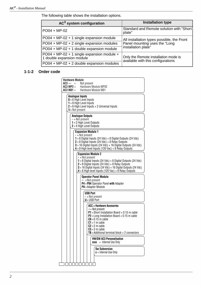
The following table shows the installation options.
1-1-2 Order code
AC3 system configuration Installation type
PO04 + MP-02 Standard and Remote solution with “Short plate”
PO04 + MP-02 + 1 single expansion module All installation types possible, the Front Panel mounting uses the “Long installation plate”
PO04 + MP-02 + 2 single expansion modules
PO04 + MP-02 + 1 double expansion module
PO04 + MP-02 + 1 single expansion module + 1 double expansion module Only the Remote installation mode is
available with this configurationsPO04 + MP-02 + 2 double expansion modules
Hardware ModuleAC3 --- = Not presentAC3 MP2 = Hardware Module MP02AC3 M81 = Hardware Module M81
Analogue Inputs0 = 6 High Level Inputs1 = 8 High Level Inputs2 = 6 High Level Inputs + 2 Universal InputsN = Not present
Analogue Outputs- = Not present1 = 2 High Level Outputs2 = 4 High Level Outputs
Expansion Module 1- = Not present1 = 8 Digital Inputs (24 Vdc) + 8 Digital Outputs (24 Vdc)2 = 8 Digital Inputs (24 Vdc) + 8 Relay Outputs3 = 16 Digital Inputs (24 Vdc) + 16 Digital Outputs (24 Vdc)4 = 8 High level Inputs (120 Vac) + 8 Relay Outputs
Operator Panel Module-- = Not presentP4 = P04 Operator Panel with AdapterPA = Adapter Module
USB Port- = Not presentU = USB Port
ACC = Hardware Accesories-- = Not presentP1 = Short Installation Board + 0.15 m cableP2 = Long Installation Board + 0.15 m cableC0 = 0.15 m cableC1 = 1 m cableC2 = 2 m cableC3 = 3 m cableTB = Additional terminal block + 2 connectors
HW/SW AC3 Personalisationxxxx = Internal Use Only
Sw Subversionx = Internal Use Only
Expansion Module 2- = Not present1 = 8 Digital Inputs (24 Vdc) + 8 Digital Outputs (24 Vdc)2 = 8 Digital Inputs (24 Vdc) + 8 Relay Outputs3 = 16 Digital Inputs (24 Vdc) + 16 Digital Outputs (24 Vdc)4 = 8 High level Inputs (120 Vac) + 8 Relay Outputs

Chapter 1 - Product Description
3
1-2 Physical dimensions
1-2-1 System dimensions
Standard mounting
When installing the System for the Standard mounting mode, it can use two different mount-ing plates depending on the number of expansion modules that are to be installed.
Dimensions with the display adapter and the short mounting plate
Dimensions with the display adapter and the long mounting plate
ACAC 3
xxxxxxxxxxxxxxxxx
LOC
-123.4
DI1
DI2
DI3
DI4
1234.561234.56
1234.56
1234.56
SPLockg/h
1234.56
1234.56
Auto
Loc
X0X1
81
156
215
13
sigmaPAC
LAN X1 X0
X0X1
RUNERR
PWRBAT
RESET
8DI MP-02
242 3131
686 7575
4
8
8DO
2 5 6 73 4 81
Ch.
6AI
1 3
4AO
2 4
INPUT:24VDC
OUTPUT:24VDC-0,5A
INPUT:mA,V
2AI
OUTPUT:mA, V
(TC,RTD,mV,POT)
(OPZ.)
RS
mA, V
POWER
Ch.
Ch.
F
E
7 8 10
5 6 7 8 5 6 7
1 2 3 4 1 2 3
1 2 4 5 6 7 83 109 111 2 3
+
-
+
-
+
- 8
4
2 5 6 73 44
+
-
5
+
-
6
P
1
+
8
-
9 11 12 1413
+
-
+
-
+
-
1 32
+
-
4
bcom
A BV mA
A BV mA
P bcom
RS
X0X1
380
13
X0X1
MP-D1sigmaPACsigmaPAC
LAN X1 X0
X0X1
RUNERR
PWRBAT
RESET
8DI MP-02
242 3131
686 7575
4
8
8DO
2 5 6 73 4 81
Ch.
6AI
1 3
4AO
2 4
INPUT:24VDC
OUTPUT:24VDC-0,5A
INPUT:mA,V
2AI
OUTPUT:mA, V
(TC,RTD,mV,POT)
(OPZ.)
RS
mA, V
POWER
Ch.
Ch.
F
E
7 8 10
5 6 7 8 5 6 7
1 2 3 4 1 2 3
1 2 4 5 6 7 83 109 111 2 3
+
-
+
-
+
- 8
4
2 5 6 73 44
+
-
5
+
-
6
P
1
+
8
-
9 11 12 1413
+
-
+
-
+
-
1 32
+
-
4
bcom
A BV mA
A BV mA
P bcom
RS
AC3 - Installation Manual
4
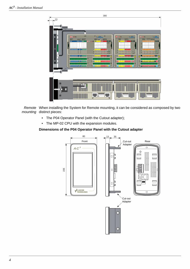
Remote mounting
When installing the System for Remote mounting, it can be considered as composed by two distinct pieces:
• The P04 Operator Panel (with the Cutout adapter);
• The MP-02 CPU with the expansion modules.
Dimensions of the P04 Operator Panel with the Cutout adapter
X0X1
380
13
MP-D1sigmaPAC
LAN X1 X0
X0X1
RUNERR
PWRBAT
RESET
8DI MP-02
242 3131
686 7575
4
8
8DO
2 5 6 73 4 81
Ch.
6AI
1 3
4AO
2 4
INPUT:24VDC
OUTPUT:24VDC-0,5A
INPUT:mA,V
2AI
OUTPUT:mA, V
(TC,RTD,mV,POT)
(OPZ.)
RS
mA, V
POWER
Ch.
Ch.
F
E
7 8 10
5 6 7 8 5 6 7
1 2 3 4 1 2 3
1 2 4 5 6 7 83 109 111 2 3
+
-
+
-
+
- 8
4
2 5 6 73 44
+
-
5
+
-
6
P
1
+
8
-
9 11 12 1413
+
-
+
-
+
-
1 32
+
-
4
bcom
A BV mA
A BV mA
P bcom
RS
Front Rear
AC 3
80
156
13 35
Cut-out Adapter
Cut-out Adapter
Chapter 1 - Product Description
5
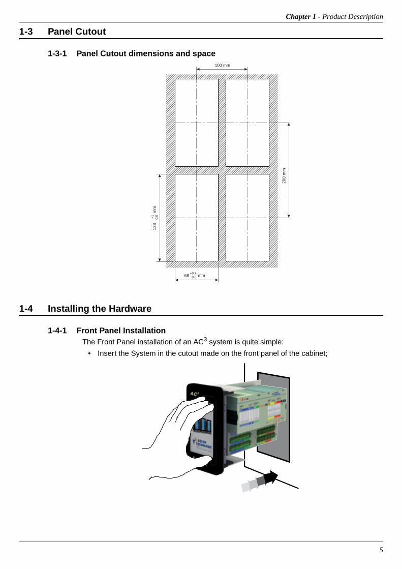
1-3 Panel Cutout
1-3-1 Panel Cutout dimensions and space
1-4 Installing the Hardware
1-4-1 Front Panel InstallationThe Front Panel installation of an AC3 system is quite simple:
• Insert the System in the cutout made on the front panel of the cabinet;
138
mm
+1
0.0
68 mm+0.7
0.0
200
mm
100 mm
AC3 - Installation Manual
6
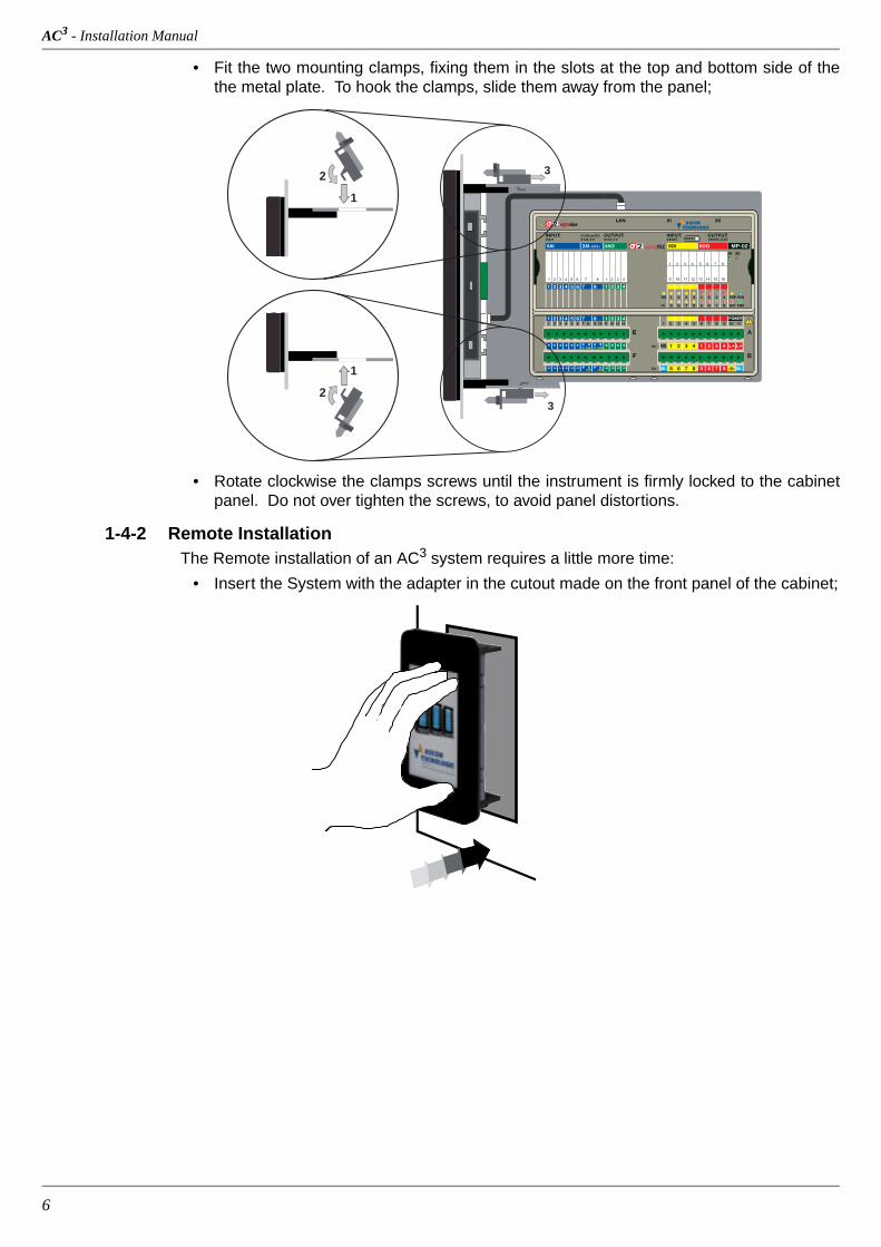
• Fit the two mounting clamps, fixing them in the slots at the top and bottom side of the the metal plate. To hook the clamps, slide them away from the panel;
• Rotate clockwise the clamps screws until the instrument is firmly locked to the cabinet panel. Do not over tighten the screws, to avoid panel distortions.
1-4-2 Remote InstallationThe Remote installation of an AC3 system requires a little more time:
• Insert the System with the adapter in the cutout made on the front panel of the cabinet;
sigmaPAC
LAN X1 X0
X0X1
RUNERR
PWRBAT
RESET
8DI MP-02
242 3131
686 7575
4
8
8DO
2 5 6 73 4 81
Ch.
6AI
1 3
4AO
2 4
INPUT:24VDC
OUTPUT:24VDC-0,5A
INPUT:mA,V
2AI
OUTPUT:mA, V
(TC,RTD,mV,POT)
(OPZ.)
RS
mA, V
POWER
Ch.
Ch.
F
E
7 8 10
5 6 7 8 5 6 7
1 2 3 4 1 2 3
1 2 4 5 6 7 83 109 111 2 3
+
-
+
-
+
- 8
4
2 5 6 73 44
+
-
5
+
-
6
P
1
+
8
-
9 11 12 1413
+
-
+
-
+
-
1 32
+
-
4
bcom
A BV mA
A BV mA
P bcom
RS
3
3
1
2
1
2

Chapter 1 - Product Description
7
• Insert the four mounting clamps, in the rear side of the P04 Operator Panel as illus-trated;
• Now mount a retaining screw in the hole present in each clamp;
• Rotate clockwise the four clamps screws until the instrument is firmly locked to the cab-inet panel. Do not over tighten the screws, to avoid panel distortions;
• The MP-02 CPU and the expansion modules must be mounted on the dedicated DIN rail located in the same cabinet or, in a remote installation) in a different one. The Operator Panel and the CPU communicate through the Ethernet cable.
Rear side
Insertionpoint
Final position
Insertionpoint
Insertionpoints
Final position

AC3 - Installation Manual
8
Installing the modules on a
DIN rail
Mounting Position
Select a mounting position in accordance with the distances indicated in the illustration that follows:
• Mount the modules vertically;
• In order to help the air ventilation flow, respect the distances between modules and walls.
Mounting/Removing the modules on/from the DIN rail
Mounting Instructions
1.Close the spring slide, then clip the upper part of the module on the rail;
2.Rotate the module downwards till to the click;
Removing Instructions
Switch OFF the Power Supply;3.Lower the spring slide by inserting a flat-blade screw-
driver as indicated;
4.Turn and lift the module upwards.
Connecting the expansion
modules
The I/O modules are already set.
The I/O expansion modules (max. 2) must be mounted on the right of the last mounted module.
The modules (CPU included) must be powered OFF when connected to each other.
All the modules must be removed from the DIN rail before to connect or disconnect the bus.
1. Switch OFF the Power Supply;
2. Insert the connector of the bus in the rightmost module. A position key identifies the insertion versus of the connector;
3. Mount the modules on the DINrail.
To remove the I/O expansion modules invert the mounting sequence described.
min. 60
64
min. 100
min. 80
Mounting position (mm)
1
2
CLICK
3
4

9
Chapter 2 Hardware Description
2-1 Technical specification
2-1-1 AC3 System Assembly
The AC3 System is composed by a P04 Touch Screen Panel device and an MP-02 Control Unit. The system, optionally, can be installed as splitted version where the P04 Panel can be installed remotely from the MP-02 Unit.
The data exchange between the two devices is performed through an Ethernet Communcations.

AC3 - Installation Manual
10
2-1-2 P04 Operator Panel
Display characteristics
Storage characteristics
Communication characteristics
Electrical characteristics
Mechanical characteristics
Environmentalcharacteristics
Item DescriptionLCD type TFT display
Screen dimension 4.3”
Screen format 16/9
Touch-screen Resistive
Resolution 480 x 272
Number of colours 262 k
Back light LED
Item DescriptionRAM 128 MB
Flash 128 MB (Operating System + Program + 16 MB user space)
Memory card MicroSD (max. capacity 8GB)
USB 2.0 full speed (max. distance <3 m)
Item DescriptionEthernet 10/100Mb/s (max. distance <30 m)
RS485 Not available
Item DescriptionPower Supply 24VAC/DC, ±10%
Current consumption 300mA @ 24VDC
Internal fuse Not available
Item DescriptionDimensions (H x L x W) 83 x 159 x 28 mm
Cutout68 x 138 (P04 with front panel mounting adapter)
68 x 127 (panel only)
Weight 200 g
Item DescriptionOperating Temperature 0... 55°C
Storage Temperature -20... +60°C
Relative Humidity 85% RH
Protection degree Front panel: IP65, Rear side: IP20
CE standards EN61151-3, 61000-3-3:1995+A1:2001+A2:2005
Chapter 2 - Hardware Description
11
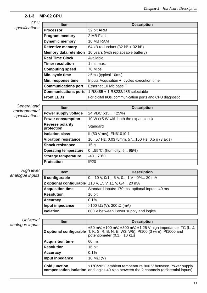
2-1-3 MP-02 CPU
CPU specifications
General and environmental specifications
High level analogue inputs
Universal analogue inputs
Item DescriptionProcessor 32 bit ARM
Program memory 2 MB Flash
Dynamic memory 16 MB RAM
Retentive memory 64 kB redundant (32 kB + 32 kB)
Memory data retention 10 years (with replaceable battery)
Real Time Clock Available
Timer resolution 1 ms max.
Computing speed 70 Mips
Min. cycle time ≥5ms (typical 10ms)
Min. response time Inputs Acquisition + cycles execution time
Communications port Ethernet 10 Mb base T
Communications ports 1 RS485 + 1 RS232/485 selectable
Front LEDs For digital I/Os, communication ports and CPU diagnostic
Item DescriptionPower supply voltage 24 VDC (-15... +25%)
Power consumption 10 W (+5 W with both the expansions)
Reverse polarity protection Standard
Isolation class II (50 Vrms), EN61010-1
Vibration resistance 10...57 Hz, 0.0375mm, 57...150 Hz, 0.5 g (3 axis)
Shock resistance 15 g
Operating temperature 0…55°C; (humidity: 5... 95%)
Storage temperature -40…70°C
Protection IP20
Item Description6 configurable 0... 10 V, 0/1... 5 V, 0... 1 V - 0/4... 20 mA
2 optional configurable ±10 V, ±5 V, ±1 V, 0/4... 20 mA
Acquisition time Standard inputs: 170 ms, optional inputs: 40 ms
Resolution 16 bit
Accuracy 0.1%
Input impedance >100 kΩ (V); 300 Ω (mA)
Isolation 800 V between Power supply and logics
Item Description
2 optional configurable±50 mV, ±100 mV, ±300 mV, ±1.25 V high impedance, TC (L, J, T, K, S, R, B, N, E, W3, W5), Pt100 (3 wire), Pt1000 and potentiometer (0.1... 10 kΩ)
Acquisition time 60 ms
Resolution 16 bit
Accuracy 0.1%
Input inpedance 10 MΩ (V)
Cold junction compensation Isolation
≤1°C/20°C ambient temperature 800 V between Power supply and logics 40 Vpp between the 2 channels (differential inputs)

AC3 - Installation Manual
12
Analogue Outputs
Digital Inputs
Digital Outputs
2-1-4 Installation Kit
The installation kit is a mandatory item when the AC3 System is to be installed in place of an AC Station or Front Panels mounted.
It consists of some hardware parts to allow the front panel installation:
• Front panel Adapter;
• 2 Allen screws to install the P04 touch screen display in the front panel adapter;
• Mounting plate with a DIN rail that allows the installation of the MP-02;
• 4 conical head Allen screws to assemble the mounting plate to the front panel adapter.
• 2 clamps to fix the structure to the font panel.
Item Description0/2/4 optional configurable ±10 V (±25 mA max.), 0/4... 20 mA
Update time 35 ms
Resolution 13 bit
Accuracy 0.1%
Isolation 800 V between Power supply and logics
Item Description8... 40 with expansions 24 VDC (On: 5... 30 V, Off: 0... 3 V)
Max. input frequency 80 Hz
Type Sink
Protection Reverse polarity and overvoltage
Isolation 800 V between Power supply and logics
Compliance IEC/EN 61131-2 (type 2)
Item Description8... 40 with expansions 24VDC, 0.5 A
Type Source (PNP)
Protection Overvoltage and short circuit
Isolation 800V between Power supply and logics
P04
Front paneladapter
Mounting plate
MP-02
Clamp
Clamp
DIN Rail
Chapter 2 - Hardware Description
13
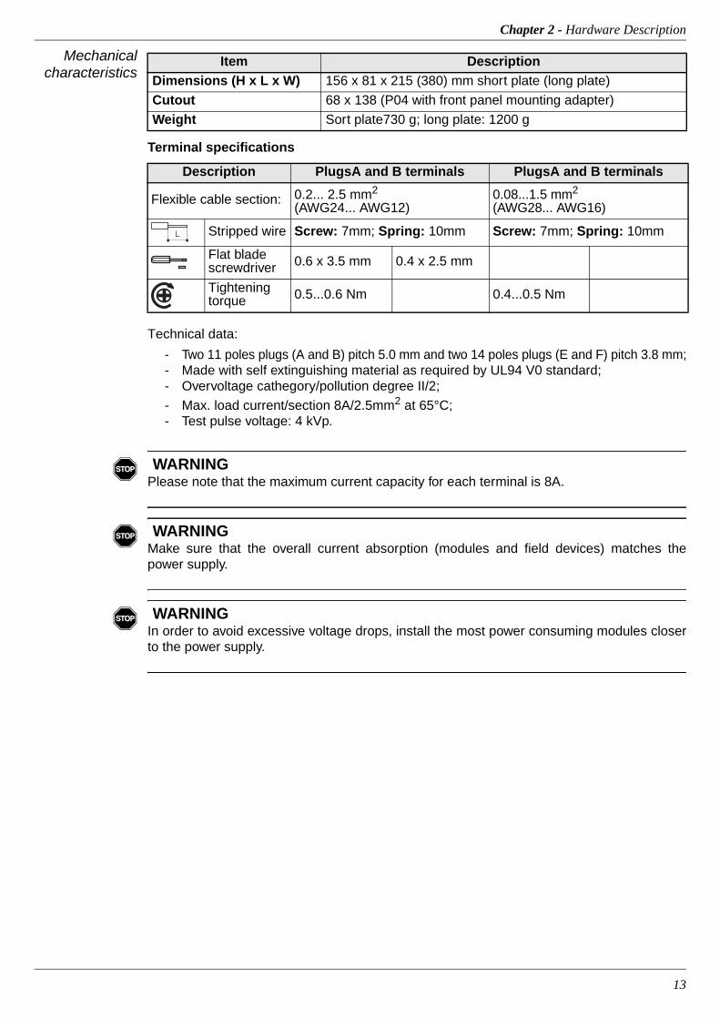
Mechanical characteristics
Terminal specifications
Technical data:
- Two 11 poles plugs (A and B) pitch 5.0 mm and two 14 poles plugs (E and F) pitch 3.8 mm;- Made with self extinguishing material as required by UL94 V0 standard;- Overvoltage cathegory/pollution degree II/2;
- Max. load current/section 8A/2.5mm2 at 65°C;- Test pulse voltage: 4 kVp.
� WARNING Please note that the maximum current capacity for each terminal is 8A.
� WARNING Make sure that the overall current absorption (modules and field devices) matches the power supply.
� WARNING In order to avoid excessive voltage drops, install the most power consuming modules closer to the power supply.
Item DescriptionDimensions (H x L x W) 156 x 81 x 215 (380) mm short plate (long plate)
Cutout 68 x 138 (P04 with front panel mounting adapter)
Weight Sort plate730 g; long plate: 1200 g
Description PlugsA and B terminals PlugsA and B terminals
Flexible cable section: 0.2... 2.5 mm2
(AWG24... AWG12)0.08...1.5 mm2
(AWG28... AWG16)
Stripped wire Screw: 7mm; Spring: 10mm Screw: 7mm; Spring: 10mm
Flat blade screwdriver 0.6 x 3.5 mm 0.4 x 2.5 mm
Tightening torque 0.5...0.6 Nm 0.4...0.5 Nm
L
AC3 - Installation Manual
14
2-2 Hardware Description
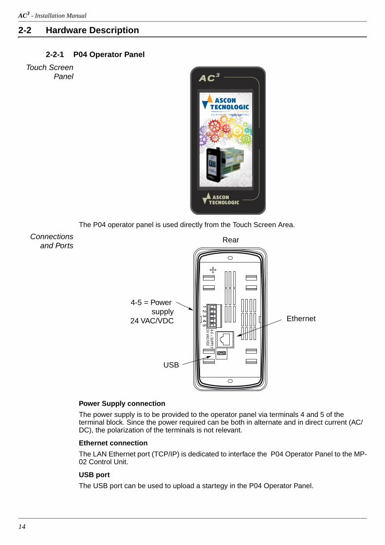
2-2-1 P04 Operator Panel
Touch Screen Panel
The P04 operator panel is used directly from the Touch Screen Area.
Connections and Ports
Power Supply connection
The power supply is to be provided to the operator panel via terminals 4 and 5 of the terminal block. Since the power required can be both in alternate and in direct current (AC/DC), the polarization of the terminals is not relevant.
Ethernet connection
The LAN Ethernet port (TCP/IP) is dedicated to interface the P04 Operator Panel to the MP-02 Control Unit.
USB port
The USB port can be used to upload a startegy in the P04 Operator Panel.
ACAC 3
Rear
USB
Ethernet
4-5 = Power supply
24 VAC/VDC

Chapter 2 - Hardware Description
15
2-2-2 MP-02 CPU
Integrated I/Os The AC3 system base MP-02 unit has up to 28 I/O ports:
6 AI 6 analogue inputs configurable for mA, V;
2 AI 2 optional universal or high level isolated analogue inputs configurable for: - Thermocouples (L, J, T, K, S, R, B, N, E, W3, W5); - RTD (PT100, PT1000); - ±mA, ±V linear inputs; - Potentiometers.
4 AO 4 optional high level analogue outputs;
RS RUN/STOP program functionality;
8 DI General Purpose Digital Inputs;
8 DO Isolated General Purpose Digital Outputs.
� WARNING The RESET button does not restart the CPU or the 1131 application, but resets all the stored set-up parameters and restores the defaut parameters (as well as those set by the user).
RS232/485Communication/ConfigurationPort Connector (X0)
RS485 Modbus Connector (X1)
Ethernet 10 Base Tport (LAN) + 2 LANstatus LEDs
Run/Stopterminal (A1) and RS status LED
Digital input terminals(A2...A4, B2...B4)
Digital output terminals(A6...A9, B6...B9)
Power Supply Terminals = +24 Vac/dc (A10, A11) = Ground (B10) = 0V (B1, B11)
Diagnostics LEDs• = ERR• = RUN• = BAT• = PWR
Analogueinputterminals(E1...E6,F1...F6)
Analogueinputterminals(E7...E10,F6...F10)
Analogueoutputterminals(E11...E14F11...F14)
8 digital output LEDs (red)
8 digital inputLEDs (yellow)
Expansion busconnector
Serial portsX0, X1 activity LEDs (green)
RESET button
Serial ports configurationmicroswitches
AC3 - Installation Manual
16
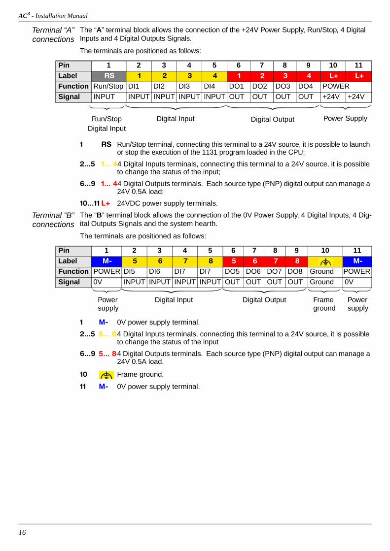
Terminal “A” connections
The “A” terminal block allows the connection of the +24V Power Supply, Run/Stop, 4 Digital Inputs and 4 Digital Outputs Signals.
The terminals are positioned as follows:
1 RS Run/Stop terminal, connecting this terminal to a 24V source, it is possible to launch or stop the execution of the 1131 program loaded in the CPU;
2...5 1... 44 Digital Inputs terminals, connecting this terminal to a 24V source, it is possible to change the status of the input;
6...9 1... 44 Digital Outputs terminals. Each source type (PNP) digital output can manage a 24V 0.5A load;
10...11 L+ 24VDC power supply terminals.
Terminal “B” connections
The “B” terminal block allows the connection of the 0V Power Supply, 4 Digital Inputs, 4 Dig-ital Outputs Signals and the system hearth.
The terminals are positioned as follows:
1 M- 0V power supply terminal.
2...5 5... 84 Digital Inputs terminals, connecting this terminal to a 24V source, it is possible to change the status of the input
6...9 5... 84 Digital Outputs terminals. Each source type (PNP) digital output can manage a 24V 0.5A load.
10 Frame ground.
11 M- 0V power supply terminal.
Pin 1 2 3 4 5 6 7 8 9 10 11Label RS 1 2 3 4 1 2 3 4 L+ L+Function Run/Stop DI1 DI2 DI3 DI4 DO1 DO2 DO3 DO4 POWER
Signal INPUT INPUT INPUT INPUT INPUT OUT OUT OUT OUT +24V +24V
Power SupplyDigital OutputDigital InputRun/StopDigital Input
Pin 1 2 3 4 5 6 7 8 9 10 11Label M- 5 6 7 8 5 6 7 8 M-Function POWER DI5 DI6 DI7 DI7 DO5 DO6 DO7 DO8 Ground POWER
Signal 0V INPUT INPUT INPUT INPUT OUT OUT OUT OUT Ground 0V
PowerDigital OutputDigital InputPower Framesupply ground supply
Chapter 2 - Hardware Description
17
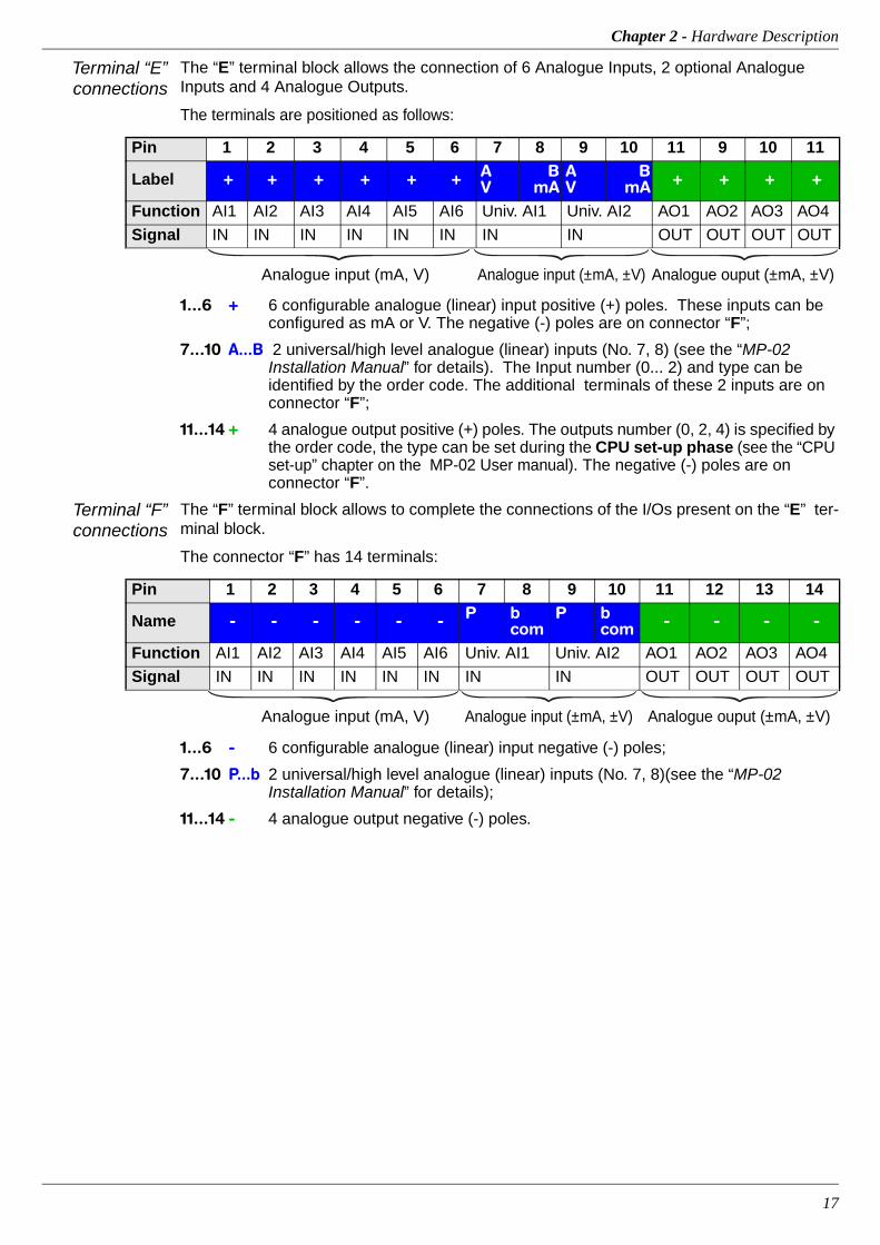
Terminal “E” connections
The “E” terminal block allows the connection of 6 Analogue Inputs, 2 optional Analogue Inputs and 4 Analogue Outputs.
The terminals are positioned as follows:
1...6 + 6 configurable analogue (linear) input positive (+) poles. These inputs can be configured as mA or V. The negative (-) poles are on connector “F”;
7...10 A...B 2 universal/high level analogue (linear) inputs (No. 7, 8) (see the “MP-02 Installation Manual” for details). The Input number (0... 2) and type can be identified by the order code. The additional terminals of these 2 inputs are on connector “F”;
11...14 + 4 analogue output positive (+) poles. The outputs number (0, 2, 4) is specified by the order code, the type can be set during the CPU set-up phase (see the “CPU set-up” chapter on the MP-02 User manual). The negative (-) poles are on connector “F”.
Terminal “F” connections
The “F” terminal block allows to complete the connections of the I/Os present on the “E” ter-minal block.
The connector “F” has 14 terminals:
1...6 - 6 configurable analogue (linear) input negative (-) poles;
7...10 P...b 2 universal/high level analogue (linear) inputs (No. 7, 8)(see the “MP-02 Installation Manual” for details);
11...14 - 4 analogue output negative (-) poles.
Pin 1 2 3 4 5 6 7 8 9 10 11 9 10 11
Label + + + + + + A V
B mA
A V
B mA + + + +
Function AI1 AI2 AI3 AI4 AI5 AI6 Univ. AI1 Univ. AI2 AO1 AO2 AO3 AO4
Signal IN IN IN IN IN IN IN IN OUT OUT OUT OUT
Analogue input (mA, V) Analogue input (±mA, ±V) Analogue ouput (±mA, ±V)
Pin 1 2 3 4 5 6 7 8 9 10 11 12 13 14
Name - - - - - - P b com
P b com - - - -
Function AI1 AI2 AI3 AI4 AI5 AI6 Univ. AI1 Univ. AI2 AO1 AO2 AO3 AO4
Signal IN IN IN IN IN IN IN IN OUT OUT OUT OUT
Analogue input (mA, V) Analogue input (±mA, ±V) Analogue ouput (±mA, ±V)
AC3 - Installation Manual
18
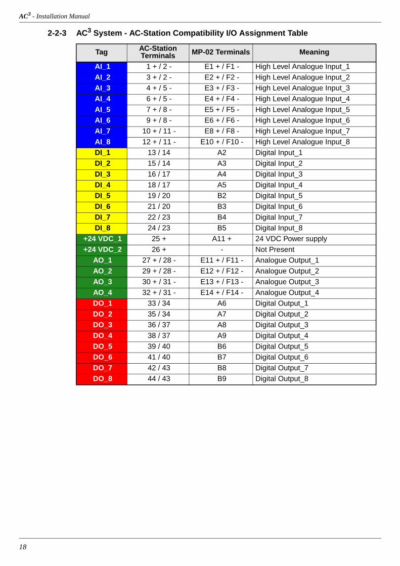
2-2-3 AC3 System - AC-Station Compatibility I/O Assignment Table
Tag AC-Station Terminals MP-02 Terminals Meaning
AI_1 1 + / 2 - E1 + / F1 - High Level Analogue Input_1
AI_2 3 + / 2 - E2 + / F2 - High Level Analogue Input_2
AI_3 4 + / 5 - E3 + / F3 - High Level Analogue Input_3
AI_4 6 + / 5 - E4 + / F4 - High Level Analogue Input_4
AI_5 7 + / 8 - E5 + / F5 - High Level Analogue Input_5
AI_6 9 + / 8 - E6 + / F6 - High Level Analogue Input_6
AI_7 10 + / 11 - E8 + / F8 - High Level Analogue Input_7
AI_8 12 + / 11 - E10 + / F10 - High Level Analogue Input_8
DI_1 13 / 14 A2 Digital Input_1
DI_2 15 / 14 A3 Digital Input_2
DI_3 16 / 17 A4 Digital Input_3
DI_4 18 / 17 A5 Digital Input_4
DI_5 19 / 20 B2 Digital Input_5
DI_6 21 / 20 B3 Digital Input_6
DI_7 22 / 23 B4 Digital Input_7
DI_8 24 / 23 B5 Digital Input_8
+24 VDC_1 25 + A11 + 24 VDC Power supply
+24 VDC_2 26 + - Not Present
AO_1 27 + / 28 - E11 + / F11 - Analogue Output_1
AO_2 29 + / 28 - E12 + / F12 - Analogue Output_2
AO_3 30 + / 31 - E13 + / F13 - Analogue Output_3
AO_4 32 + / 31 - E14 + / F14 - Analogue Output_4
DO_1 33 / 34 A6 Digital Output_1
DO_2 35 / 34 A7 Digital Output_2
DO_3 36 / 37 A8 Digital Output_3
DO_4 38 / 37 A9 Digital Output_4
DO_5 39 / 40 B6 Digital Output_5
DO_6 41 / 40 B7 Digital Output_6
DO_7 42 / 43 B8 Digital Output_7
DO_8 44 / 43 B9 Digital Output_8

Chapter 2 - Hardware Description
19
2-2-4 Diagnostic LEDsReferring to the image inserted at the previous page a description of the LEDs functions is given in the table below.
Note: The ERR LED flashing sequence has a specific meaning which needs to be acknowledged by the user as described on the dedicated MP-02 User manual.
LED Colour Action (note 1) DescriptionRS Yellow ON RS input active (RUN program)
ERR Red
Flickering (10Hz) Checksum error in RETAIN data
Single flash CRC error in the configuration file, reset to default
Double flash Problem during file system mount
Triple flash Checksum VAR % RETAIN error (NOTE 2)
RUN GreenON 1131 program running
OFF 1131 program stopped or not present
PWR Green ON Power Supply present
BAT Yellow ON Backup battery low
Sequence MeaningBlinking The LED blinks at a frequence of 2.5 Hz (slow)
Flickering The LED blinks at a frequence of 10 Hz (fast)
Single flash The LED lits once for at least 200 ms
Double flash The LED lits twice with pulses of 200 ms each
Triple flash The LED lits three with pulses of 200 ms each

AC3 - Installation Manual
20
21
Chapter 3 Electrical Connections
3-1 Electric safety and electromagnetic compatibility
Class II instrument, rear panel mounting.
This instrument has been designed in compliance with:
• Regulations on electrical equipment:
- according to regulations on the essential protection requirements in electrical equip-ment EN 61010-1
• Regulations on Electromagnetic Compatibility according to:
- Regulations on RF emissions: EN61000-6-4 industrial environments;
- Regulation on RF immunity: EN61000-6-2 industrial equipment and system.
It is important to understand that it’s responsibility of the installer to ensure the compliance of the regulations on safety requirements and EMC.
This controller has no user serviceable parts and requires special equipments and special-ised engineers to be repaired. For this purpose, the manufacturer provides technical assist-ance and the repair service for its Customers. Please, contact your nearest Agent for further information.
All the information and warnings about safety and electromagnetic compatibility are marked with the sign, at the side of the note.
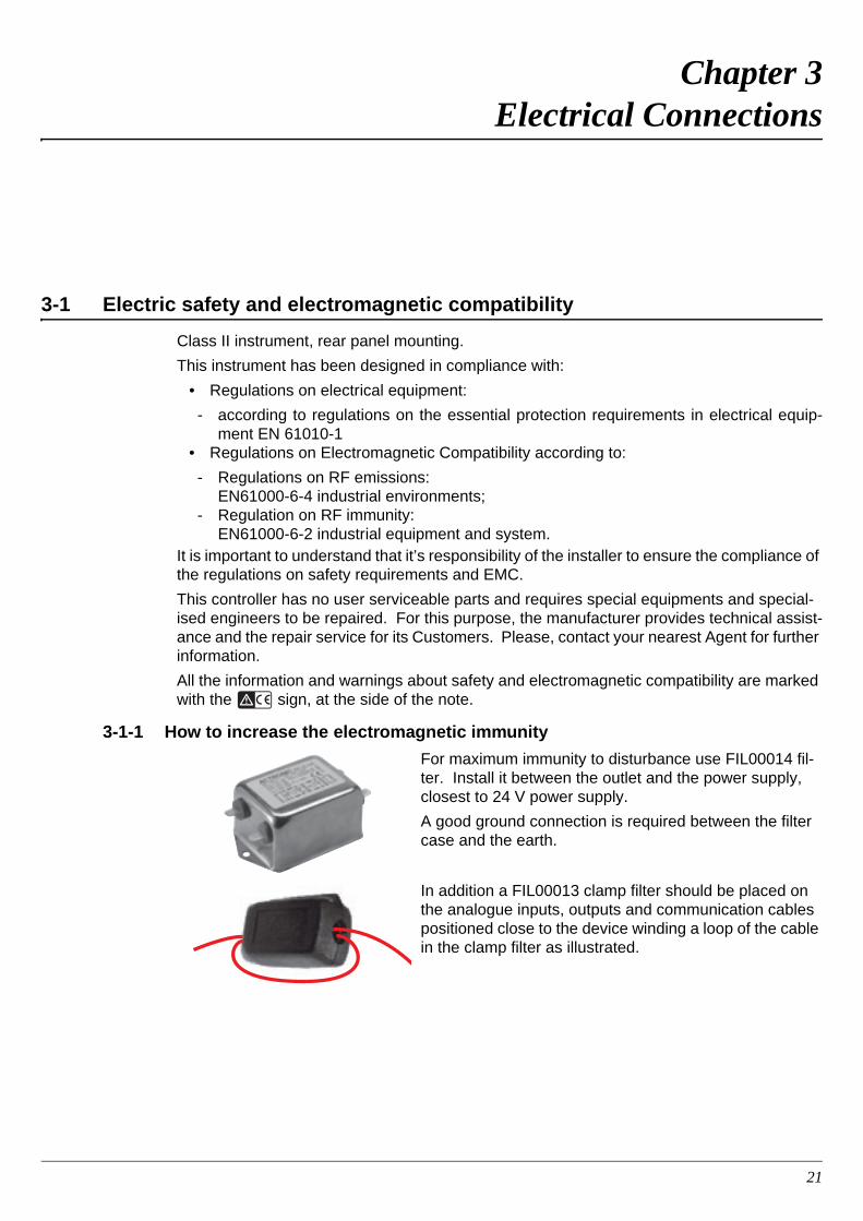
3-1-1 How to increase the electromagnetic immunity
For maximum immunity to disturbance use FIL00014 fil-ter. Install it between the outlet and the power supply, closest to 24 V power supply.
A good ground connection is required between the filter case and the earth.
In addition a FIL00013 clamp filter should be placed on the analogue inputs, outputs and communication cables positioned close to the device winding a loop of the cable in the clamp filter as illustrated.
AC3 - Installation Manual
22
3-2 Installation Precautions and Notes
3-2-1 CE Installation Precautions All wirings must comply with the local regulations;
• The supply wiring should be routed away from the power cables;
• Avoid to use electromagnetic contactors, power relays and high power motors nearby;
• Avoid power units nearby, especially if controlled in phase angle;
• Keep the low level sensor input wires away from the power lines and the output cables. If this is not achievable, use shielded cables on the sensor input, with the shield con-nected to earth.
3-2-2 Installation Notes• Make sure that the power supply voltage is the same indicated on the instrument label.
• Switch ON the power supply only after all the electrical connections have been com-pleted.
3-3 Power Supply Connections
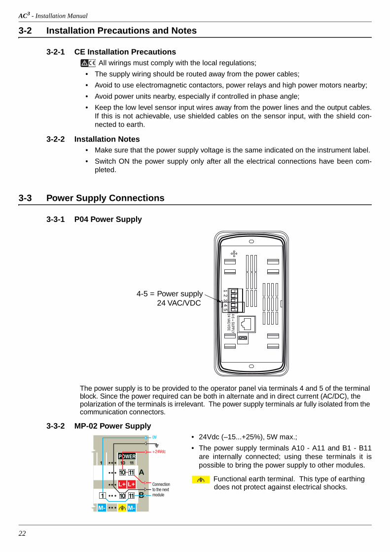
3-3-1 P04 Power Supply
The power supply is to be provided to the operator panel via terminals 4 and 5 of the terminal block. Since the power required can be both in alternate and in direct current (AC/DC), the polarization of the terminals is irrelevant. The power supply terminals ar fully isolated from the communication connectors.
3-3-2 MP-02 Power Supply• 24Vdc (–15...+25%), 5W max.;
• The power supply terminals A10 - A11 and B1 - B11 are internally connected; using these terminals it is possible to bring the power supply to other modules.
Functional earth terminal. This type of earthing does not protect against electrical shocks.
12
34
5
4-5 = SUPPLY24 VAC/VDC
4-5 = Power supply 24 VAC/VDC
POWER10 111
0V
+24Vdc
1110
1 10 11
Connectionto the nextmodule
Chapter 3 - Electrical Connections
23
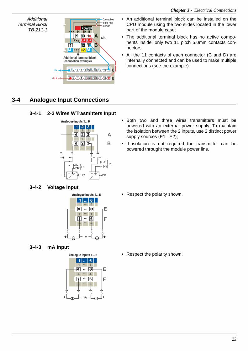
Additional Terminal Block
TB-211-1
• An additional terminal block can be installed on the CPU module using the two slides located in the lower part of the module case;
• The additional terminal block has no active compo-nents inside, only two 11 pitch 5.0mm contacts con-nectors;
• All the 11 contacts of each connector (C and D) are internally connected and can be used to make multiple connections (see the example).
3-4 Analogue Input Connections
3-4-1 2-3 Wires WTrasmitters Input• Both two and three wires transmitters must be
powered with an external power supply. To maintain the isolation between the 2 inputs, use 2 distinct power supply sources (E1 - E2);
• If isolation is not required the transmitter can be powered throught the module power line.
3-4-2 Voltage Input• Respect the polarity shown.
3-4-3 mA Input• Respect the polarity shown.
CPU
Additional terminal block(connection example)
C
D+24 V
0 V
POWER109 11
119 10
1 10 11
Connectionto the nextmodule
0V
24V
PV1
0V24V
PV2
E2E1
Analogue inputs 1... 6
1 2 3
Analogue inputs 1... 6
V
E
F
61 ... 6
...
...
...
...
...
mA
E
F
6
Analogue inputs 1... 6
1 ... 6...............
AC3 - Installation Manual
24
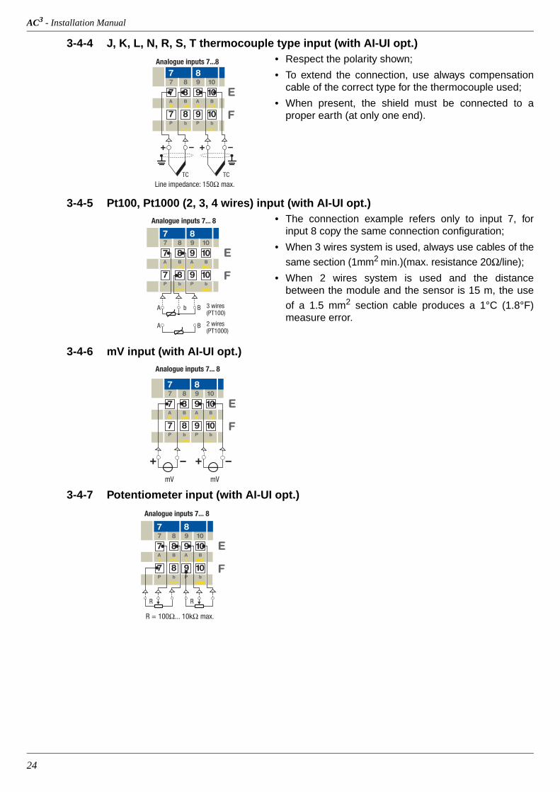
3-4-4 J, K, L, N, R, S, T thermocouple type input (with AI-UI opt.)• Respect the polarity shown;
• To extend the connection, use always compensation cable of the correct type for the thermocouple used;
• When present, the shield must be connected to a proper earth (at only one end).
3-4-5 Pt100, Pt1000 (2, 3, 4 wires) input (with AI-UI opt.)• The connection example refers only to input 7, for
input 8 copy the same connection configuration;
• When 3 wires system is used, always use cables of the
same section (1mm2 min.)(max. resistance 20Ω/line);
• When 2 wires system is used and the distance between the module and the sensor is 15 m, the use
of a 1.5 mm2 section cable produces a 1°C (1.8°F) measure error.
3-4-6 mV input (with AI-UI opt.)
3-4-7 Potentiometer input (with AI-UI opt.)
Line impedance: 150Ω max.
E
F
87
BAmAV
bPcom
TC
109
BAmAV
bPcom
TC
Analogue inputs 7...8
7
7 8
7 8
8
9 10
9 10
E
F
87
BAmAV
bcom
109
BAmAV
bPcom
A B 2 wires(PT1000)
3 wires(PT100)
A Bb
Analogue inputs 7... 8
7
7 8
7 8
8
9 10
9 10P
E
F
87
BAmAV
bPcom
109
BAmAV
bPcom
mV
Analogue inputs 7... 8
mV
7
7 8
7 8
8
9 10
9 10
R
R = 100Ω... 10kΩ max.
E
F
87
BAmAV
bPcom
109
BAmAV
bPcom
R
Analogue inputs 7... 8
7
7 8
7 8
8
9 10
9 10

Chapter 3 - Electrical Connections
25
3-4-8 High level inputs (with AI-HL opt.)
3-5 Digital Input Connections
3-5-1 Digital Inputs 1...8 Type II (EN61131-2)
Contact Input
• Respect the polarity;
• When present the shield must be connected to a proper earth (at only one end).
3-5-2 Digital Inputs 1...8 Type II (EN61131-2)
Source (PNP) device
• Respect the polarity.
• When present the shield must be connected to a proper earth (at only one end);
• If the input device needs to be powered by the module, verify that the current consumption does not exceed the power supply limits.
3-6 Analogue Output Connections
3-6-1 Analogue outputs 1... 4 (opt.)• The user can choose the number of analogue output
installed in the central unit (0, 2 or 4 outputs);
• Respect the polarity.
E
F
87
BAmAV
bPcom
109
BAmAV
bPcom
V
High level analogue inputs 7... 8-10... +10V/0...10 V
E
F
87
BAmAV
bPcom
109
BAmAV
bPcom
High level analogue inputs 7... 8-20... 20/0... 20/4... 20 mA
V 4...20 mA4...20 mA
7
7 8
7 8
8
9 10
9 10
7
7 8
7 8
8
9 10
9 10
A
B
1 2 3
1 2
5 6
RS
M-
+24Vdc
Connec t t o 24 Vdc
NO contact
Additional terminal block
A
B
1 2 3
1 2
5 6
RS
M-
+24Vdc
PNP device
Connec t t o 24 Vdc
Additional terminal block
Respect the polarity shown
E
F
1211
++
-
1413
++
--
Analogue load
1
11 12
3
13 14
-
2 4
11 12 13 14
Load

AC3 - Installation Manual
26
3-7 Digital Output Connections
3-7-1 Digital Output 1...8 (PNP) Source Type• 24 Vdc, 0.5A digital outputs;
• Respect the polarity;
• When present the shield must be connected to a proper earth (at only one end).
3-8 Communications connections
On the CPU module are present all the communications ports. Connect the cable of the var-ious interfaces as follows.
3-8-1 X0 port RS232/485 Service/Modbus Port connector
The RS232 Service Port can be used to configure the CPU and its devices using a dumb VT100 ter-minal. The RJ45 RS232/485 Service Port connec-tor is located in the upper side (on the right) of the CPU (see “2-2-2 MP-02 CPU” on page 15). Look-ing the hole of the plug the 8 contacts are arranged as illustrated in the draw.
Service Port connection
1. The RS232 cable must be shorter than 15 m.2. The hardware default configuration of the Service Port is:
- Baud Rate: 9600 bps;- Data: 8 bit;- Stop bit: 1;- Parity: none;- Flow Control: none.
Note: Consult the “MP-02 User Manual” for details about the service port configuration.
Service Port signals
The signals present at the RJ45 connector of the Service Port are:
Load
POWER
11
Additionalterminalblock
10
0V
...
...
...
...
...
...
6
16
65
...
10
10
11
11
A
B
D
Upper side
Front side of the CPU
Female RJ45RS232/485service portconnector
X0
Pin Signal1 D+ (RS485)
2 D- (RS485)
3 GND (RS485)
4 GND (RS232)
5 RX (RS232)
6 TX (RS232)
7 NC
8 NC

Chapter 3 - Electrical Connections
27
3-8-2 X1 Port RS485 Modbus Port connector
The RS485 Modbus Port can be used to connect a Modbus fieldbus. The RJ45 RS485 Modbus Port connector is located in the upper side (on the left) of the CPU (see “2-2-2 MP-02 CPU” on page 15). Looking the hole of the plug the 8 contacts are ar-ranged as illustrated in the draw.
RS485 Modbus Port Connection
1. The RS232 cable must be shorter than 15 m.2. The default configuration of the Service Port is:
- Baud Rate: 9600 bps;- Data: 8 bit;- Stop bit: 1;- Parity: none;- Flow Control: none.
Note: The selection of DIP switches 4 and 5 must match the sellection operated by the configuration section (consult the “MP-01 User Manual”).
RS485 Modbus Port signals
The signals present at the RJ45 connector of the Modbus Port are:
X0/X1 Ports DIP Switches
The Communications Ports electrical settings can be selected through the microswitches located between the Serial Port connectors.
The following table describes the selectable options.
X0X1
Female RJ45RS485 Modbusport connector
Upper side
Front side of the CPU
Pin Signal1 D+ (RS485)
2 D- (RS485)
3 GND (RS485)
4 NC
5 NC
6 NC
7 NC
8 NC
Aspect Switch Port Description ON OFF Default1 X1 Termination Resistance (110Ω) Enabled Disabled OFF
2 X1 Pull-Down Line polarization Enabled Disabled OFF
3 X1 Pull-Up Line polarization Enabled Disabled OFF
4 X0 RS232 Selection Enabled Disabled ON
5 X0 RS485 Selection RS485 RS232 OFF
6 X0 Termination Resistance (110Ω) Enabled Disabled OFF
7 X0 Pull-Down Line polarization Enabled Disabled OFF
8 X0 Pull-Up Line polarization Enabled Disabled OFF

AC3 - Installation Manual
28
3-8-3 LAN - Ethernet TCP/IP port connector
The Ethernet TCP/IP port RJ45 connector is located in the upper side of the CPU (see “2-2-2 MP-02 CPU” on page 15). Looking the hole of the plug the 8 contacts are arranged as illustrated in the draw.
Ethernet signals
The signals present on the RJ45 ethernet connector are those standard for all Ethernet TCP/IP connection.
To connect correctly the CPU to the programming computer, use an ethernet “cross cable” in case of direct connection (no HUB or network router between the PC and the CPU); otherwise, if the Computer is not directly connected to the CPU, use a “patch cable” to connect the CPU.
Front sideof the CPU
Female RJ45Ethernetconnector
Upper side
Pin Signal1 TX+
2 TX-
3 RX+
4 NC
5 NC
6 RX-
7 NC
8 NC

29
Chapter 4 Replacing the RTC Battery
• With the blade of a screwdriver, free the 8 slots (at the top and bottom of the CPU) in order to remove the rear cover from the rest of the the housing;
� WARNING The procedure to replace the RTC battery must be done with the 24Vdc power supply CONNECTED (the MP-01 Powered ON).
1
2

AC3 - Installation Manual
30
• Once the box of the CPU is open, locate the battery position and slide it out from the terminals (see image);
• Replace the battery with the positive pole facing the rear panel of the CPU and the neg-ative one in contact wuith the printed circuit (see image). Pay attention not to touch the battery with the fingers;
• After the battery has been changed, the user can close the CPU rear cover:
1. The rear cover must be positioned in order to put the two slides which lock the box to the DIN rail in the lower part (look at the CPU front to identify the upper and lower CPU side).
2. After the two parts of the CPU have been aligned, press the two parts of the box in order to re-insert the 8 slots opened at the beginning of this setting procedure.
+ (positive)

31
Appendix A Accessories
A-1 Connection accessories
A-1-1 11 poles connectors
With screw terminals: AP-S2/SPINA-V11
With spring terminals: AP-S2/SPINA-M11
A-1-2 14 poles connectors
With screw terminals: AP-S2/SPINA-V14
With spring terminals: AP-S2/SPINA-M14
A-1-3 Additional terminal block
AP-S2/TB-211-1

AC3 - Installation Manual
32
A-2 Power Supply
A-2-1 Power supply 75W - 3A/24Vdc
APS2ALDR75-24
A-2-2 Power supply 120W - 5A/24Vdc
APS2ALDR12024
A-3 Disturbance Protection Accesories
A-3-1 EMC Filter
FIL00014
A-3-2 EMC Clamp filter
FIL00013
Chapter A - Accessories
33
A-4 Network Connection Accesories
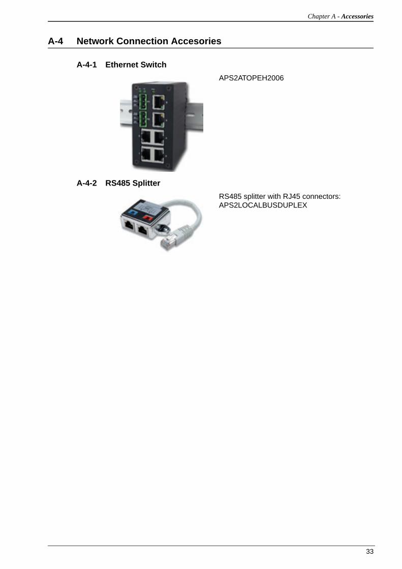
A-4-1 Ethernet Switch
APS2ATOPEH2006
A-4-2 RS485 Splitter
RS485 splitter with RJ45 connectors: APS2LOCALBUSDUPLEX

AC3 - Installation Manual
34
Ascon Tecnologic Srl
Via Indipendenza, 56
27029 Vigevano (PV) Italia
Tel. +39/0381/69871
Fax +39/0381/698730
All rights reserved. No parts of this publication may be reproduced, in any form, without Ascon Tecnologic S.r.l. written permission.
Every care has been taken preparing this manual; the document has been carefully reviewed for technical accuracy. In the event that technical or typographical errors exist Ascon Tecnologic S.r.l. reserves the right to make changes without any notice.
In no event shall Ascon Tecnologic S.r.l. be liable for any damages arising out of or related to this document or the information contained in it.
If errors are suspected, please contact Ascon Tecnologic S.r.l. at the above ad-dress.