ac-motors LARGE DRIVES - w3app.siemens.com · † Motor torque range 5 – 40 kNm † Motor rated...
52
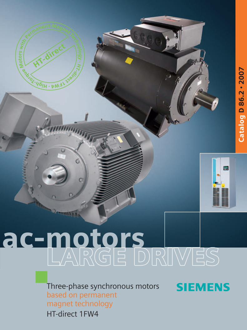
ac-motors HT-direct H i g h - T o r q u e M o t o r s w i t h P e r m a n e n t - M a g n e t T e c h n o l o g y · H T - d i r e c t 1 F W 4 · Three-phase synchronous motors based on permanent magnet technology HT-direct 1FW4 Catalog D 86.2 • 2007 LARGE DRIVES LARGE DRIVES LARGE DRIVES
Transcript of ac-motors LARGE DRIVES - w3app.siemens.com · † Motor torque range 5 – 40 kNm † Motor rated...
ac-motors
HT-dire
ct
High-Torque
Mo
tors
wit
hPe
rmanent-Magnet Techn
olog
y·H
T-direct1FW4·
Three-phase synchronous motorsbased on permanentmagnet technologyHT-direct 1FW4
Ca
talo
g D
86
.2 •
20
07
LARGE DRIVESLARGE DRIVESLARGE DRIVES
Related catalogs
Low-Voltage Motors D 81.1IEC Squirrel-Cage Motors
Order No.: German: E86060-K5581-A111-A1 English: E86060-K5581-A111-A1-7600
Asynchronous Motors D 86.1Standardline N-compact 1LA8 H-compact 1LA4Order No.: German: E86060-K5586-A111-A1English: E86060-K5586-A111-A1-7600
SINAMICS G130 D 11Drive Converter Chassis Units SINAMICS G150 Drive Converter Cabinet Units75 kW to 800 kWOrder No: German: E86060-K5511-A101-A3 English: E86060-K5511-A101-A3-7600
SINAMICS S120 D 21.1Drive System 0.12 kW to 1200 kW Order No.:German: E86060-K5521-A111-A2 English: E86060-K5521-A111-A2-7600
SINAMICS S150 D 21.3Drive converter cabinet units 75 kW to 1200 kW Order No.: German: E86060-K5521-A131-A1 English: E86060-K5521-A131-A1-7600
Catalog CA 01 CA 01The Offline Mall ofAutomation and DrivesOrder No.: CD E86060-D4001-A110-C5-7600DVD: E86060-D4001-A510-C5-7600
A&D Mall
Internet:http://www.siemens.com/automation/mall

s
© Siemens AG 2007
Three-phase synchronous motorsbased on permanent magnet technologyHT-direct 1FW4
Catalog D 86.2 · 2007
Introduction
1
Selection and ordering
HT-direct motors 1FW4 with water cooling (water-jacket cooling)
2
HT-direct motors 1FW4 with air cooling (forced ventilation)
3
Configuring
4
Appendix
5
The products and sys-tems described in this catalog are manufac-tured under application of a quality manage-ment system certified by DQS in accordance with EN ISO 9001 (Certifi-cate Registration No. 002241 QM UM).The certificate is recog-nized in all IQ Net coun-tries.

0/2 Siemens D 86.2 · 2007
Siemens Automation and Drives.Welcome
More than 60,000 people aiming for the same goal: increasing your competitiveness. That's Siemens Automation and Drives.
We offer you a comprehensive portfolio for sustained success in your sector, whether you're talking automa-tion engineering, drives or electrical installation sys-tems. Totally Integrated Automation (TIA) and Totally Integrated Power (TIP) form the core of our offering. TIA and TIP are the basis of our integrated range of products and systems for the manufacturing and process industries as well as building automation. This portfolio is rounded off by innovative services over the entire life cycle of your plants.
Learn for yourself the potential our products and systems offer. And discover how you can permanently increase your productivity with us.
Your regional Siemens contact can provide more infor-mation. He or she will be glad to help.

0/3Siemens D 86.2 · 2007

Notes
0/4 Siemens D 86.2 · 2007
Siemens D 86.2 · 2007
1/2 Overview1/3 Benefits1/3 Application
1/3 Order No. code
1/4 Protection strategy
1/5 General technical data1/5 Converter-fed operation1/7 Motor protection1/7 Bearing monitoring1/8 Electrical design1/8 Motor connection and connection
boxes1/9 Mechanical design
Introduction
Introduction
1/2 Siemens D 86.2 · 2007
1■ Overview
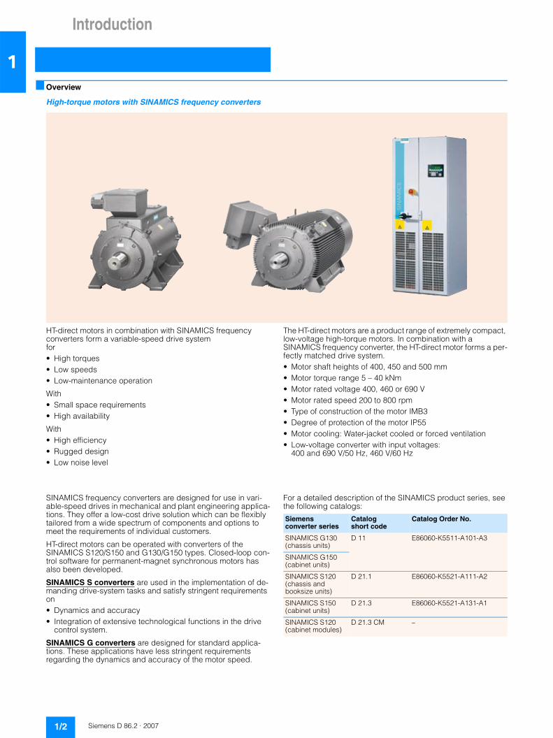
High-torque motors with SINAMICS frequency converters
HT-direct motors in combination with SINAMICS frequency converters form a variable-speed drive system for• High torques• Low speeds• Low-maintenance operation
With• Small space requirements• High availability
With• High efficiency• Rugged design• Low noise level
The HT-direct motors are a product range of extremely compact, low-voltage high-torque motors. In combination with a SINAMICS frequency converter, the HT-direct motor forms a per-fectly matched drive system.• Motor shaft heights of 400, 450 and 500 mm• Motor torque range 5 – 40 kNm• Motor rated voltage 400, 460 or 690 V• Motor rated speed 200 to 800 rpm• Type of construction of the motor IMB3• Degree of protection of the motor IP55• Motor cooling: Water-jacket cooled or forced ventilation• Low-voltage converter with input voltages:
400 and 690 V/50 Hz, 460 V/60 Hz
SINAMICS frequency converters are designed for use in vari-able-speed drives in mechanical and plant engineering applica-tions. They offer a low-cost drive solution which can be flexibly tailored from a wide spectrum of components and options to meet the requirements of individual customers.
HT-direct motors can be operated with converters of the SINAMICS S120/S150 and G130/G150 types. Closed-loop con-trol software for permanent-magnet synchronous motors has also been developed.
SINAMICS S converters are used in the implementation of de-manding drive-system tasks and satisfy stringent requirements on• Dynamics and accuracy• Integration of extensive technological functions in the drive
control system.
SINAMICS G converters are designed for standard applica-tions. These applications have less stringent requirements regarding the dynamics and accuracy of the motor speed.
For a detailed description of the SINAMICS product series, see the following catalogs:
Siemensconverter series
Catalogshort code
Catalog Order No.
SINAMICS G130 (chassis units)
D 11 E86060-K5511-A101-A3
SINAMICS G150 (cabinet units)
SINAMICS S120 (chassis and booksize units)
D 21.1 E86060-K5521-A111-A2
SINAMICS S150 (cabinet units)
D 21.3 E86060-K5521-A131-A1
SINAMICS S120 (cabinet modules)
D 21.3 CM –
Introduction
1/3Siemens D 86.2 · 2007
1■ Benefits
The benefits of the HT-direct motors:• With slow-running drives, the efficiency of the HT-direct motors
is approximately 2 to 3% higher than for similar drive con-cepts. For a 1000 kW motor, this results in a saving of 33 kW, which is an annual saving of approximately 15000 € for an operating time of 8 hours per day.
• The multi-pole drive design ensures that the space require-ment and mass of the motors are lower than for similar induction machines. The slow-running motors of the HT-direct series obviate the need for a gearbox in many cases (reduction in engineering, assembly and maintenance outlay, lower investment and lower operating costs).
• Efficient, optimally matched drive system, SINAMICS con-verter and HT-direct motor for operation without encoders.
• Thanks to their long service life (nominal bearing lifetime > 60000 hours), HT-direct motors are maintenance-low and have a high availability especially for applications in which a gearbox can be omitted.
• Environmentally friendly system (where applicable, no disposal of gearbox oil is necessary; energy-saving drive system).
■ Application
Permanent-magnet synchronous motors are used in combina-tion with converters as slow-running direct drives, e.g. for paper machines, in the steel and plastics industries and in shipbuilding.
Ordering example
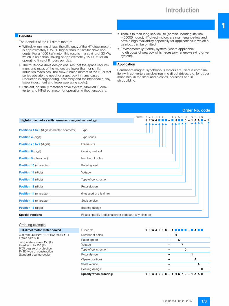
Order No. code
Position 1 2 3 4 5 6 7 8 9 10 11 12 13 14 15 16
High-torque motors with permanent-magnet technology 1 F W 4 7 7 7 – 7 H 7 7 0 – 1 A A 7 – Z
Positions 1 to 3 (digit, character, character) Type
Position 4 (digit) Type series
Positions 5 to 7 (digits) Frame size
Position 8 (digit) Cooling method
Position 9 (character) Number of poles
Position 10 (character) Rated speed
Position 11 (digit) Voltage
Position 12 (digit) Type of construction
Position 13 (digit) Rotor design
Position 14 (character) (Not used at this time)
Position 15 (character) Shaft version
Position 16 (digit) Bearing design
Special versions Please specify additional order code and any plain text
HT-direct motor, water-cooled Order No. 1 F W 4 5 0 8 – 1 7 7 7 7 – 7 A 7 7
400 rpm; 40 kNm; 1676 kW; 690 V* → Frame size 508Temperature class 155 (F) Used acc. to 155 (F) IP55 degree of protection IM B3 type of construction Standard bearing design
Number of poles – H
Rated speed – C
Voltage – 7
Type of construction – 0
Rotor design – 1
(Spare position) – A
Shaft version – A
Bearing design – 0
Specify when ordering: 1 F W 4 5 0 8 – 1 H C 7 0 – 1 A A 0

Introduction
Protection strategy
1/4 Siemens D 86.2 · 2007
1Reverse power
Due to the permanent magnets in the rotor, magnetic flux is con-tinuously present in the motor and for each revolution of the rotor, a voltage is generated at the motor terminals, even when the feeding converter is switched off and disconnected from the supply system.
Power from feeding converter
Also, when the rotor is at a standstill, voltage can still be present at the motor terminals if the feeding converter has not yet been switched off or the DC link circuit of the converter is not yet dis-charged.
Notes on safety, application and design
If work is to be performed on the drive system (converter and/or motor), the following safety measures must be implemented:• The converter must be isolated from the supply system by a
switch (isolating switch or circuit-breaker).• Prevent any rotary motion of the motor.• A separate protective device must be used for plants, in which
the rotor can be accelerated by an active load, for example a circuit breaker must be used.
• The field weakening range is limited to 120%. In case of an ac-tive load (rotor can be accelerated by the plant) the DC link must be protected against overspeed/overvoltage.
Safety precautions when working on Maintenance or repair on the motor and/or the converter after commissioning of the drive system may only be car-ried out under the following preconditions.
Motor terminal box Important!
Only permissible when the rotor is at a standstill!
Before opening the motor terminal box it must be ensured that
• the rotor is at a standstill, • the converter is disconnected from the supply and • the DC link of the converter is discharged.
Converter On rotor standstill. Before opening the converter it must be ensured that
• the converter is disconnected from the supply, • the DC link of the converter is discharged and • the rotor is at a standstill.
With a rotating rotor that is cou-pled depending on the plant.
Before opening the converter it must be ensured that
• the converter is disconnected from the supply, • the DC link of the converter is discharged and • that the (coupled) motor is electrically isolated from the con-
verter by means of a suitable switch (for SINAMICS S120 Cabinet Modules a corresponding circuit-breaker on the out-put side can be ordered with the converter opion L34).

Introduction
General technical data
1/5Siemens D 86.2 · 2007
1■ Converter-fed operation
Converters
SINAMICS S converters
The SINAMICS S120 and S150 converters allow regenerative feedback into the supply system. The motor can be operated, if required, with a rotor position encoder.
SINAMICS G converters
The SINAMICS G130 and G150 converters do not allow regen-erative feedback into the supply system. These converters also do not support the use of a rotor position encoder. The motor can only be operated without encoder.
Encoderless speed control
Encoderless speed and torque control has been developed for the HT-direct motors.
The motors can be started up from a standstill without encoders. After a few revolutions, the converter can calculate the speed and position of the rotor from the voltage induced by the mag-nets in the motor winding. Motor operation down to standstill is possible. For highly dynamic torque control, an encoder is required at low speeds. For connection to a rotating machine (capture) in encoderless operation, a voltage measuring module is required. This module is offered as an option (K 51) for the converter and can be used instead of an encoder module.
Synchronized operation of multiple drives
The accuracy for speed or frequency for synchronized operation of several drives is 0.01% related to the maximum speed or fre-quency over a period of one second. A SINAMICS converter is required for each motor.
Approach
Start-up from standstill with full rated torque is possible for encoderless motors as well as for motors with speed encoders.
Creep operation
Water-jacket-cooled and forced-ventilated motors can be oper-ated for 3 hours with 1/100 of the rated speed. At this operating point, the converter is only permitted to be operated at 50% of the rated current. A speed encoder is required for torque-con-trolled operation in this range.
In creep mode, if the torque is more than the applicable torque at 50% of rated current, a converter with a higher rating must be selected.
Operation in the field weakening range
The field weakening range for the HT-direct motors is limited to 20% of the rated speed. The magnets in the rotor do not allow conventional field weakening, so field weakening can only be achieved by the injection of a phase-displaced current by the converter. In the case of high field-weakening speeds, this would require an increase in converter frame size. The limited field-weakening range also ensures that the DC-link voltage of the converter does not exceed the maximum permissible value in case of pulse blocking due to the induced voltage of the mo-tor.
Overload capability
The overload capability of the motor converter system is deter-mined by the design of the converter and motor (see SINAMICS catalogs). The motor and converter can be temporarily over-loaded by up to 50%. The basic load current of the converter that is available is reduced by overload requirements which may re-quire selection of a larger converter. For higher overloads and more complex duty cycles, please submit an enquiry.
Cable lengths between the motor and converter
The maximum cable length for shielded motor connection cables is 300 m without any additional measures (see the sec-tion “Bearings and bearing currents”).
Duty type
The standard duty type is S1. For other duty types, please spec-ify the duty cycle.
Use according to temperature class 130 (previously temperature class B) available on request.
All converters must be operated at a pulse frequency of ≥ 2.5 kHz due to the eddy-current losses that arise in the magnets.

Introduction
General technical data
1/6 Siemens D 86.2 · 2007
1Bearings and bearing currents
When operating multiphase AC machines by a converter, an electrical bearing stress results from a capacitive induced volt-age via the bearing lubricating film, depending on the principle being used. The physical cause of this is the common-mode voltage at the converter output: The sum of the three phase-to-neutral voltages is not zero at all times, unlike with direct on-line operation. The high-frequency, pulse-shaped common-mode voltage brings about a residual current, which closes back to the converter's DC link via the machine's internal capacitances, the machine housing and the earthing circuit. The machine's inter-nal capacitances include the main insulation winding capaci-tance, the geometric capacitance between the rotor and stator, the lubricating film capacitance and the capacitance of any bearing insulation that may be present. The current level via the internal capacitances is proportional to the common-mode volt-age regulation (i(t) = C · du/dt).
In order to apply currents to the motor which are sinusoidal as far as possible (smooth running, oscillation torques, stray losses), a high pulse frequency is required for the converter's output volt-age. The related (very steep) switching edges of the converter output voltage (and also, therefore, of the common-mode volt-age) cause correspondingly high capacitive currents and volt-ages on the machine's internal capacitances.
In the worst-case scenario, the capacitive voltage induced via the bearing can lead to random punctures of the bearing lubri-cating film, thus damaging the bearing/causing premature wear. The current pulses caused by the puncture in the lubricating film are referred to as EDM (Electrostatic Discharge Machining) cur-rents, although this is not primarily a question of an electrostatic effect, but more of (partial) punctures of insulating material, i.e., of partial discharges.
This physical effect, which occurs in isolated cases, has mostly been observed in connection with larger motors.
EMC-compliant installation of the drive system is a basic prereq-uisite for preventing premature bearing damage via bearing cur-rents.
The most important measures for reducing bearing currents:• Use of cables with a symmetrical cable cross-section
(see Figure below)
• Use of motor reactors (converter option L08)• Preference given to a supply with insulated neutral point
(IT system)• Use of grounding cables with low impedance in a large fre-
quency range (DC up to approximately 70 MHz): for example, plaited copper ribbon cables, HF litz wires
• Separate HF equipotential-bonding cable between motor housing and driven machine
• Separate HF equipotential-bonding cable between motor housing and converter PE busbar
• 360° HF contacting of the cable shield on the motor housing and the converter PE busbar. This can be achieved using EMC screwed glands on the motor end and EMC shield clips on the converter end, for example.
• Common-mode filters at the converter output• The HT-direct motors are equipped with an electrically insu-
lated bearing housing at NDE.
Thermal limit characteristic and field-weakening range
Due to the speed-independent cooling of the HT-direct motors, no torque reduction or only a relatively minor torque reduction (depending on their speed range) is required for operation at constant load torque and with wide speed ranges.
Guide values for the maximum load torques at various speeds can be obtained from the diagrams below:
L1
L2 L3
L1
L2 L3
L1
L2 L3
PE PE
PE PE
Concentric
copper or aluminium shieldSteel armor G_
D0
11
_E
N_
00
00
5
n n / N
M / M
N
0.00.0 0.2 0.4 0.6 0.8 1.0 1.2
G_D086_EN_00007a
Field weakening
0.2
1.2
1.0
0.4
0.6
0.8
Speed
To
rqu
e

Introduction
General technical data
1/7Siemens D 86.2 · 2007
1■ Motor protection
In addition to the current-dependent overload protection device located in the connecting leads, we recommend that you also monitor the temperature rise in the motor - and consequently the winding temperature - with the aid of the KTY 84-130 tempera-ture sensors built into the stator winding as standard.
Winding temperature detection with KTY 84-130 temperature sensors (standard)
The KTY 84-130 sensor is a semiconductor sensor that changes its resistance depending on temperature in accordance with a defined, approximately linear characteristic. Two temperature sensors are built into the winding overhang as standard, whereby one sensor is used as a spare. The temperature is eval-uated in the Siemens converter using the resistance of the tem-perature sensor. The required temperature for alarm and tripping can be set on the converter.
Two auxiliary terminals are provided for connection in the termi-nal box.
Optional winding temperature detection with PTC ther-mistors (thermistor motor protection)
Protection against thermal overloading of the motor is also pro-vided by PTC thermistors installed in the winding overhang. When a limit temperature is reached (rated tripping tempera-ture), the PTC thermistor undergoes a step change in resistance. This is evaluated by a tripping unit and can be used to open aux-iliary circuits.
Two auxiliary terminals are provided in the terminal box for con-necting three built-in temperature sensors for shutdown.
Optional winding temperature detection with PT100 resis-tance thermometers
PT100 resistance thermometers can also be installed in the winding overhang. An additional auxiliary terminal box is re-quired for connection.
Changes in temperature are transferred to a display device in the form of changes in resistance. The indicator is not included in the scope of supply.
■ Bearing monitoring
Standard bearing vibration monitoring using SPM shock-pulse measurement
Measuring nipples for SPM shock-pulse measurement are screwed into the bearing housing at the drive end and non-drive end as standard.
Optional bearing temperature detection with PT100 resis-tance thermometers
As an option, bearing thermometers can be screwed into the bearing housings at the drive end and non-drive end. The wires are routed through an additional terminal box.
Changes in temperature are transferred to a display device in the form of changes in resistance. The indicator is not included in the scope of supply.
R
k
= 2 mA D
U
3
2.5
2
1.5
1
0.5
0 50 100 150 200 250 300 °C 0
G_D086_EN_00006

Introduction
General technical data
1/8 Siemens D 86.2 · 2007
1■ Electrical design
Speeds
The rated motor speeds (rpm)• 200• 300• 400• 500• 600• 800 describe the transition speeds of the motor design. Above the transition speed, a field weakening range of up to 20% is possible (e.g. a motor with a rated speed 500 rpm can be operated up to 600 rpm).
Voltages and frequencies
EN 60034-1 differentiates between Category A (combination of voltage deviation ±5% and frequency deviation ±2%) and Category B (combination of voltage deviation ±10% and fre-quency deviation +3/–5%) for voltage and frequency fluctua-tions.
The motors can supply their rated torque in both Category A and Category B. In Category A, the temperature rise is approx. 10 K higher than during normal operation. According to the standard, longer operation is not recommended for Category B.
The tolerance for HT-direct motors is in accordance with DIN EN 60034-1 in all cases. A rated voltage range is, therefore, not specified on the rating plate.
Windings and insulation
For the versions with windings of round wire, the well-proven DURIGNIT 2000 insulation system in temperature class 155 is used. Frame sizes ≥ 450 have shaped-coil windings whose in-sulation system is based on the same materials and whose wind-ing design is adapted accordingly.
The components of the insulation system are• Varnish or mica-insulated round or flat wires for the winding
insulation • Multi-layer flat insulation material for the slot and phase insu-
lation• Solvent-free impregnated resin
The high-quality materials offer resistance to continuous high temperatures approaching temperature class 180. An impregnation technique optimized for the winding design is used that ensures a minimum resin fill level in the slot.
This ensures:• The required mechanical stiffness of the winding in the vicinity
of the slot and windings• The quality of heat dissipation to the laminated core and the
internal air circulation• Protection of the winding from environmental effects such as
humidity or corrosive chemicals.
Utilization
With the insulation system used under normal converter-fed operation, the motors are utilized according to temperature class 155 (previously: temperature class F).
■ Motor connection and connection boxes
Connecting cables
For motor currents that exceed the maximum current carrying capability of 1230 A of a terminal box, two galvanically isolated winding systems are equipped with two 1XB1 631 terminal boxes (for assignment, see the section “Selection and ordering data”).
The connecting cables must be dimensioned acc. to DIN VDE 0298.
Characteristics of the 1XB1 631 terminal box
Terminal box 1XB1 631
The possible mounting positions for the terminal boxes on the water-cooled or air-cooled motors are described in Sections 2 and 3.
Characteristics of the optional auxiliary terminal box
Line voltages 690 V, 50 Hz 400 V, 50 Hz 460 V, 60 Hz
Voltage code (11th position of the Order No.)
7 8 4
Number of terminals Quantity 12
Contact screw thread Size M16
Max. rec. conductor cross-section mm2 240
Outer cable diameter (sealing range)
mm 56 ... 68.5
Cable entry holes Size 4 x M80 x 2
Cable glands (option K57) Size 4 x M80 x 2 Z58 – Z67
Number of terminals Quantity 24
Outer cable diameter mm 11 ... 16
Cable entry holes Size 2 x M20 x 1.5
Cable glands (option K57) Size 2 x M20 x 1.5

Introduction
General technical data
1/9Siemens D 86.2 · 2007
1■ Mechanical design
Rotor construction
The rotor is fitted with permanent magnets. The magnets are integrated in the rotor and potted in resin.
For rotors installed in motors, a magnetic field cannot be detected externally.
Bearings and lubrication
The HT-direct motors are equipped as standard with one deep-groove ball bearing at DE and NDE installed in the bearing hous-ing.
The DE bearing is responsible for axial guiding of the rotor (so-called fixed bearing).
The NDE bearing is installed as a floating bearing with axial clearance in the electrically insulated bearing housing. Axial pressure springs that act on the outer ring of the deep-groove ball bearing ensure backlash-free and smooth running of the motor.
The roller bearings are greased and are equipped with a re-greasing device. The grease type, quantity and relubrication intervals are stated on the lubrication plate of the motor.
The calculated bearing lifetime is 60000 operating hours in S1 duty provided that the instructions for lubrication on the lubrica-tion plate of the motor are complied with. In practice, however, the bearing lifetime is frequently longer than this.
The compartment for storing the old grease must be sufficiently large to allow an operating time of > 60000 hours.
The requirements of the marine classification societies (Germa-nischer Lloyd, DNV, BV, LRS,ABS, CCS) are fulfilled, i.e. angular displacement is permitted in every direction up to 15° static and 22° dynamic. The requirement must be ordered with the appro-priate E.. order code.
Measuring nipples are screwed into the bearing housing as standard for bearing monitoring based on the shock-pulse method.
Bearing at DE (fixed bearing)
Bearing at NDE (floating bearing): Electrically insulated bearing cartridge, backlash-free adjusted deep-groove ball bearing
Standard bearing arrangement
Changing the bearing
It is possible to change the bearings on site. Please contact your local Siemens sales representative regarding this.
Max. motor speed
The motors can be operated up to 20% above the rated speed.
Danger: The magnetic field from a disassembled rotor can cause injury or damage to health if inappropriate tools are used.Installation and disassembly of the rotor is therefore only per-mitted to be performed at the manufacturer site.
G_
D0
86
_X
X_
00
00
8
Frame size Drive end DE bearing
Non-drive end NDE bearing
40. 6232 C3 6228 C3
45. 6236 C3 6232 C3
50. 6240 C3 6236 C3
Insulating washer
Insulating tube
Insulating ring
Plain washerof insulating material
G_
D0
86
_E
N_
00
00
9

Introduction
General technical data
1/10 Siemens D 86.2 · 2007
1Balance and vibration severity
The rotors are dynamically balanced with half key. This corre-sponds to vibration severity grade A.
DIN EN 60034-14 is concerned with the mechanical vibrations of rotating electrical machines and specifies limits. “Half key bal-ancing” is specified here based on DIN ISO 8821.
The balancing type is stamped on the face of the drive-end (DE) shaft extension.
F = Balancing with full featherkeyH = Balancing with half featherkeyN = Balancing without featherkey
Full key balancing is possible, on request, by specifying code L68 (additional charge).
Low-vibration versions can be supplied to fulfill stricter require-ments on smooth running (additional charge).
For vibration severity level B (special vibration requirements), order code K02 must be specified in the order.
Note: The tolerance of the measuring instrument can be ± 10%.
Noise
Noise is measured in a room with low reflection characteristics according to DIN EN ISO 1680, however at rated power. The noise level is specified as A-weighted measuring surface sound pressure level LpfA in dB (A). This value is the spatial average value of the sound pressure levels measured at the measuring surface. The measuring surface is a cube 1 m away from the sur-face of the motor.
The sound pressure level in converter-fed operation depend on the speed and torque of the drive application. In most cases, the values for water-cooled motors are below 82 dB(A) and for air-cooled motors they are below 85 dB(A).
Permissible cantilever forces depending on the axial forces that occur
Frame size 400, 1FW4 40. IM B3
Frame size 450, 1FW4 45. IM B3
Frame size 503/505, 1FW4 503/505 IM B3
Frame size 507/508, 1FW4 507/508 IM B3
Vibration severity grade
Limit values (rms values) for the maximum vibration level for the vibration speed in mm/s in a rigid configuration according to IEC/EN 60034-14
A 2.3
B 1.5
14000
18000
12000
10000
8000
6000
4000
2000
0
-15000 -10000 -5000 0 5000 10000 15000
N
n = 800
n = 600
n = 400
n = 200
N N
G_D086_EN_00010a
Max. tensile force on shaft end
Pe
rmis
sib
le c
an
tile
ve
r fo
rce
Max. compression force on shaft end
Cantilever force over axial force on shaft end
for nominal bearing lifetime L = 40000 hh10
0
2000
6000
4000
8000
10000
14000
12000
18000
-20000 -15000 15000 -10000 10000 -5000 5000 0
n = 200
n = 600
n = 400
n = 800
N
N N
G_D086_EN_00011a
Max. tensile force on shaft end
Cantilever force over axial force on shaft end
for nominal bearing lifetime L = 40000 hh10
Pe
rmis
sib
le c
an
tile
ve
r fo
rce
Max. compression force on shaft end
14000
16000
20000
12000
10000
8000
6000
4000
2000
0
-18000 -13000 -8000 -3000 2000 7000 12000 17000
N
n = 800
n = 600
n = 400
n = 200
N N
G_D086_EN_00012a
Max. tensile force on shaft end
Cantilever force over axial force on shaft end
for nominal bearing lifetime L = 40000 hh10
Pe
rmis
sib
le c
an
tile
ve
r fo
rce
Max. compression force on shaft end
14000
16000
12000
10000
8000
6000
4000
2000
0
-18000 -13000 -8000 -3000 2000 7000 12000 17000
N
n = 500
n = 400
n = 300
n = 200
N N
G_D086_EN_00013a
Max. tensile force on shaft end
Cantilever force over axial force on shaft end
for nominal bearing lifetime L = 40000 hh10
Pe
rmis
sib
le c
an
tile
ve
r fo
rce
Max. compression force on shaft end

Introduction
General technical data
1/11Siemens D 86.2 · 2007
1Paint finish
All motors can be repainted with commercially available paints.
All motors are painted with RAL 7030 if the color is not specified.
Special coatings with thicker layers are available on request.
Degrees of protection
HT-direct motors are designed to IP 55 degree of protection. They can be installed in dusty or humid environments. The motors can be suitable for operation in tropical climates as an option. Guide value 60% relative humidity at 40 °C ambient tem-perature. Other requirements on request.
The motors can be supplied in IP56 degree of protection on request (order code K52).
Explanation of the degrees of protection• IP55: Protection against harmful dust deposits, protection
against water jets.• IP56: Protection against harmful dust deposits, protection
against heavy water jets (non-heavy sea).
Condensation water drain hole:
If condensation water builds up in the motor it can drain through holes positioned at the lowest point in the motor housing. When the motors are delivered, these holes are sealed.
Rating plate (example for water-cooled motor)
Design Suitability of paint finish for climate group in accordance with DIN IEC 60 721, Part 2– 1
Normal paint finish (layer thickness 60 to 90 μm)
Extended: Covers moderate outdoor climates, in particular, the “cold moderate climate”, the “moderate climate”, the “moderately dry climate” and the “warm dry climate”.For indoors and outdoors under a roof not directly subjected to weather conditions The concentration of pollutants can be up to the applicable TRGS value (previously MAK value).
Short-term: Up to 120 °C
Continu-ous:
Up to 100 °C
Special paint finish (layer thickness 90 to 120 μm)
Global: Covers all statistical outdoor climates.For outdoor installations subjected to direct solar irra-diation and/or weathering over a wide temperature and moisture range. Any aggressive pollutants must not exceed a concentration of three times the TRGS value.
Short-term: Up to 140 °C
Continu-ous:
Up to 120 °C
3~MOT.
V
690 / 2x890 1675 0,83 400 55 53,3
Permanent Magnet EN/IEC 60034-1
Max. Wasserdruck / max. water pressure
80 I/min bei / at 25 °C max Kühlwasser / cooling water
S1 n 480 1/minmax
5 bar
Rotor Gew/Wt 7,4 t
A kW Hz
1FW4 508-1HC70-1AA0 NoN - U81176625010001 / 2006 IM B3 Th.Cl.F
cos 1/min Nm
40000
IP
Betrieb mit SINAMICS-Umrichter / Operation with SINAMICS Drive
G_
D0
86
_E
N_
00
01
4a
MADE IN GERMANY D-90441 Nuremberg
6
1
2
3
7
9
14
16
17
18
10
5
4
11
12
13
15
19
8
1 Motor type 2 Order No. 3 ID No. (factory No.) 4 Type of construction 5 Temperature class 6 Rated voltage [V] 7 Rated frequency [Hz] 8 Rated current [A] 9 Rated power [kW] 10 Degree of protection
11 Rated torque [Nm] 12 Rated speed [rpm] 13 Power factor 14 Rotor 15 Motor weight [t] 16 Max. water pressure [bar] 17 Required cooling water flowrate [l/min]
at max. cooling water temperature [°C] 18 Duty type 19 Max. operating speed [rpm]

Introduction
General technical data
1/12 Siemens D 86.2 · 2007
1Anti-condensation heating (optional)
Motors whose windings are at risk of condensation due to the cli-matic conditions, e.g. inactive motors in humid atmospheres or motors that are subjected to widely fluctuating temperatures can be equipped with anti-condensation heaters as an option.
Anti-condensation heating must not be switched on during oper-ation. For this purpose, an appropriate interlocking circuit with the main switch of the machine must be installed when erecting the electrical system.
For additional protection against the build-up of condensation, it is recommended that the cooling circuit of a water-cooled ma-chine is shut down during long periods of inactivity.
The anti-condensation heating available as an option must prin-cipally be switched on 1 hour after shutdown of the machine to prevent damage to the winding insulation.
For the connection of auxiliary leads, separate auxiliary terminal boxes can be mounted as an option (option M52).
Additional order codes for anti-condensation heating
Marine version (optional)
Motors for operation in a marine climate (saline sea air contain-ing up to 1 mg salt/m3 of air and 96% air humidity) can be sup-plied in a “Marine version” as an option. To prevent corrosion at the bearing seal, the shaft section under the bearing seal is coated.
For installation on deck, forced-ventilated motors must be pro-tected against flooding. The motors must also be protected against ice formation at temperatures below 0 °C (precautions must be taken against the external fan freezing solid or against freezing of the cooling water).
Standards and regulations
The motors comply with the appropriate standards and regula-tions, especially those listed in the table below.
Supply voltage Order code
230 V (~) K45
400 V (~) L08
500 V (~) L09
115 V (~) K46
460 V (~) Y83 With additional plain text: “For 460 V supply voltage”
Title IEC DIN/EN/ISO
General specifications for rotating electrical machines
IEC 60034-1IEC 60085
DIN EN 60034-1
Starting characteristics for rotating electrical machines
IEC 60034-12 DIN EN 60034-12
Terminal designations and direction of rotation for rotating electrical machines
IEC 60034-8 DIN EN 60034-8
Designation for type of construction, installation and terminal box position
IEC 60034-7 DIN EN 60034-7
Entry to terminal box – DIN 42925
Built-in thermal protection IEC 60034-11 DIN EN 60034-11
Noise limit values for rotating electrical machines
IEC 60034-9 DIN EN 60034-9
IEC standard voltages IEC 60038 DIN IEC 60038
Cooling methods for rotating electrical machines
IEC 60034-6 DIN EN 60034-6
Vibration severity of rotating electrical machines
IEC 60034-14 DIN EN 60034-14
Vibration limits – DIN ISO 10816
Degrees of protection for rotating electrical machines
IEC 60034-5 DIN EN 60034-5
Technique for measuring the emitted sound from rotating electrical machines
– DIN EN ISO 1680

Siemens D 86.2 · 2007
2/2 Overview2/2 Benefits2/3 Selection and ordering data2/5 Special versions2/8 Dimension drawings2/9 Additional information
Selection and orderingHT-direct motors 1FW4water-cooled
Selection and orderingHT-direct motors 1FW4 water-cooled
2/2 Siemens D 86.2 · 2007
2
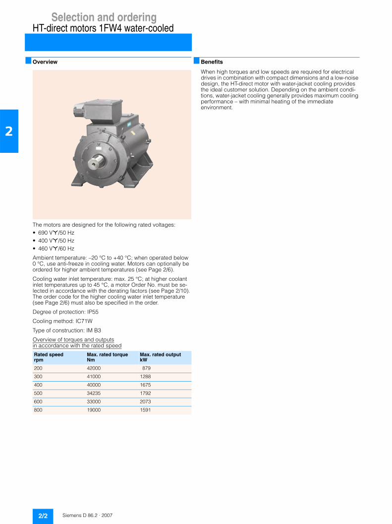
■ Overview
The motors are designed for the following rated voltages:• 690 V*/50 Hz• 400 V*/50 Hz• 460 V*/60 Hz
Ambient temperature: –20 °C to +40 °C; when operated below 0 °C, use anti-freeze in cooling water. Motors can optionally be ordered for higher ambient temperatures (see Page 2/6).
Cooling water inlet temperature: max. 25 °C; at higher coolant inlet temperatures up to 45 °C, a motor Order No. must be se-lected in accordance with the derating factors (see Page 2/10). The order code for the higher cooling water inlet temperature (see Page 2/6) must also be specified in the order.
Degree of protection: IP55
Cooling method: IC71W
Type of construction: IM B3
Overview of torques and outputsin accordance with the rated speed
■ Benefits
When high torques and low speeds are required for electrical drives in combination with compact dimensions and a low-noise design, the HT-direct motor with water-jacket cooling provides the ideal customer solution. Depending on the ambient condi-tions, water-jacket cooling generally provides maximum cooling performance – with minimal heating of the immediate environment.
Rated speed rpm
Max. rated torque Nm
Max. rated output kW
200 42000 879
300 41000 1288
400 40000 1675
500 34235 1792
600 33000 2073
800 19000 1591

Selection and orderingHT-direct motors 1FW4 water-cooled
2/3Siemens D 86.2 · 2007
2
■ Selection and ordering data
Rated torque
Rated out-put 1)
Frame size
Effi-cien-cy at 690 V
Pow-er fac-tor at 690 V
Rated current at Norm. max. torque at 690 V 2)
Mo-ment of in-ertia
Version with two galvanically isolated winding systems 3)
Order No. Weight, approx.
4/4- load
4/4- load
690 V* 400 V* 460 V* Tmax/Trated
J 690 V* 400 V* 460 V*
Nm kW % cos ϕ A A A kgm2 kg
200 rpm, IP55 degree of protection, IMB3 type of construction
9375 196 401 94.4 0.89 205 335 305 1.5 19.4 – – – 1FW4401-1HA70-1AA0 3040
11250 235 403 94.4 0.88 245 410 370 1.5 22.4 – – – 1FW4403-1HA70-1AA0 3310
13125 274 405 94.7 0.89 280 485 425 1.5 26.1 – – – 1FW4405-1HA70-1AA0 3650
15000 314 407 95.0 0.90 315 530 465 1.5 30.9 – – – 1FW4407-1HA70-1AA0 4100
16215 339 451 93.1 0.79 400 740 650 1.5 37.9 – – – 1FW4451-1HA70-1AA0 4010
18975 397 453 93.9 0.80 460 840 720 1.5 44.9 – – – 1FW4453-1HA70-1AA0 4350
21850 457 455 94.3 0.81 550 900 830 1.5 51.5 – – – 1FW4455-1HA70-1AA0 4680
27600 578 503 95.0 0.80 660 1190 990 1.5 89.3 – – – 1FW4503-1HA70-1AA0 5610
32775 686 505 94.8 0.79 870 1350 1210 1.5 102.6 – ✓ – 1FW4505-1HA70-1AA0 6110
37950 794 507 95.2 0.80 930 1720 1340 1.5 118.4 – ✓ ✓ 1FW4507-1HA70-1AA0 6680
42000 879 508 95.6 0.82 930 1600 1400 1.5 139.3 – ✓ ✓ 1FW4508-1HA70-1AA0 7440
300 rpm, IP55 degree of protection, IMB3 type of construction
9060 284 401 95.7 0.90 275 475 420 1.5 19.4 – – – 1FW4401-1HB70-1AA0 3040
10875 341 403 95.8 0.89 340 550 510 1.5 22.4 – – – 1FW4403-1HB70-1AA0 3310
12690 398 405 96.1 0.89 390 640 580 1.5 26.1 – – – 1FW4405-1HB70-1AA0 3650
14500 455 407 96.3 0.90 450 750 670 1.5 30.9 – – – 1FW4407-1HB70-1AA0 4100
15860 498 451 95.3 0.79 560 1010 840 1.5 37.9 – – – 1FW4451-1HB70-1AA0 4010
18560 583 453 95.6 0.81 700 1100 990 1.5 44.9 – – – 1FW4453-1HB70-1AA0 4350
21375 671 455 95.8 0.81 890 1390 1220 1.5 51.5 – ✓ – 1FW4455-1HB70-1AA0 4680
26700 838 503 96.2 0.81 960 1640 1440 1.5 89.3 – ✓ ✓ 1FW4503-1HB70-1AA0 5610
31705 996 505 96.3 0.80 1170 1960 1680 1.5 102.6 – ✓ ✓ 1FW4505-1HB70-1AA0 6110
36710 1153 507 96.5 0.80 1290 2330 1940 1.5 118.4 ✓ ✓ ✓ 1FW4507-1HB70-1AA0 6680
41000 1288 508 96.7 0.82 1360 2220 2190 1.5 139.3 ✓ ✓ ✓ 1FW4508-1HB70-1AA0 7440
400 rpm, IP55 degree of protection, IMB3 type of construction
8750 366 401 96.4 0.90 360 580 530 1.5 19.4 – – – 1FW4401-1HC70-1AA0 3040
10500 439 403 96.5 0.90 435 700 630 1.5 22.4 – – – 1FW4403-1HC70-1AA0 3310
12250 513 405 96.7 0.91 485 850 750 1.5 26.1 – – – 1FW4405-1HC70-1AA0 3650
14000 586 407 96.9 0.93 540 930 810 1.5 30.9 – – – 1FW4407-1HC70-1AA0 4100
15510 649 451 96.0 0.80 710 1240 1100 1.5 37.9 – ✓ – 1FW4451-1HC70-1AA0 4010
18150 760 453 96.4 0.82 800 1380 1210 1.5 44.9 – ✓ – 1FW4453-1HC70-1AA0 4350
20900 875 455 96.5 0.81 950 1590 1370 1.5 51.5 – ✓ ✓ 1FW4455-1HC70-1AA0 4680
25800 1080 503 96.8 0.83 1110 1880 1620 1.5 89.3 – ✓ ✓ 1FW4503-1HC70-1AA0 5610
30635 1283 505 96.8 0.81 1420 2290 2270 1.5 102.6 ✓ ✓ ✓ 1FW4505-1HC70-1AA0 6110
35475 1485 507 97.0 0.81 1610 4) 2270 1.5 118.4 ✓ 4) ✓ 1FW4507-1HC70-1AA0 6680
40000 1675 508 97.2 0.83 1780 4) 4) 1.5 139.3 ✓ 4) 4) 1FW4508-1HC70-1AA0 7440
Rated voltage• 460 V* 4• 690 V* 7• 400 V* 8
Special voltage 9
Other rated speed with additional plain text –Z
1) Temperature class 155 (temperature class F), used according to tempera-ture class 155 (temperature class F)
2) Maximum torque Tmax = Overload torque for 120 s (higher overload torques on request)
3) In the version with two galvanically isolated winding systems, two main terminal boxes 1XB1 631 are required.– Not applicable✓ Applicable
4) Cannot be implemented

Selection and orderingHT-direct motors 1FW4 water-cooled
2/4 Siemens D 86.2 · 2007
2
Notes for current-calculation:
The stator current from permanent-excited motors can not be calculated as usual with the rated output, converter output volt-age, power factor and efficiency. The reason is that the induced voltage at the rated point does not comply with the converter output voltage automatically. The real terminal voltage is depending on the speed, the torque and the integer number of turns.
The stator current of the 1FW4-motor series is proportional to the speed. With it the required stator current for a torque differing from the rated torque can be calculated. The stator current should be calculated exactly with the project tool „SINAMICS MICROMASTER SIZER“.
Rated torque
Rated out-put 1)
Frame size
Effi-cien-cy at 690 V
Pow-er fac-tor at 690 V
Rated current at Norm. max. torque at 690 V 2)
Mo-ment of in-ertia
Version with two galvanically isolated winding systems 3)
Order No. Weight, approx.
4/4- load
4/4- load
690 V* 400 V* 460 V* Tmax/Trated
J 690 V* 400 V* 460 V*
Nm kW % cos ϕ A A A kgm2 kg
500 rpm, IP55 degree of protection, IMB3 type of construction
8440 441 401 96.8 0.91 415 680 610 1.5 19.4 – – – 1FW4401-1HD70-1AA0 3040
10125 530 403 96.9 0.90 510 840 740 1.5 22.4 – – – 1FW4403-1HD70-1AA0 3310
11810 618 405 97.0 0.90 590 960 830 1.5 26.1 – – – 1FW4405-1HD70-1AA0 3650
13500 706 407 97.2 0.95 630 1080 930 1.5 30.9 – – – 1FW4407-1HD70-1AA0 4100
15160 793 451 96.6 0.80 880 1400 1390 1.5 37.9 – ✓ ✓ 1FW4451-1HD70-1AA0 4010
17740 928 453 96.8 0.81 1050 1600 1580 1.5 44.9 – ✓ ✓ 1FW4453-1HD70-1AA0 4350
20425 1069 455 96.9 0.82 1170 1880 1580 1.5 51.5 – ✓ ✓ 1FW4455-1HD70-1AA0 4680
24900 1303 503 97.0 0.83 1340 2200 2150 1.5 89.3 ✓ ✓ ✓ 1FW4503-1HD70-1AA0 5610
29565 1548 505 97.2 0.84 1570 4) 4) 1.5 102.6 ✓ 4) 4) 1FW4505-1HD70-1AA0 6110
34235 1792 507 97.3 0.84 1820 4) 4) 1.5 118.4 ✓ 4) 4) 1FW4507-1HD70-1AA0 6680
600 rpm, IP55 degree of protection, IMB3 type of construction
8125 510 401 97.0 0.90 490 800 710 1.5 19.4 – – – 1FW4401-1HE 70-1AA0 3040
9750 612 403 97.1 0.90 580 940 820 1.5 22.4 – – – 1FW4403-1HE 70-1AA0 3310
11375 714 405 97.2 0.90 700 1090 940 1.5 26.1 – – – 1FW4405-1HE 70-1AA0 3650
13000 816 407 97.3 0.93 750 1250 1070 1.5 30.9 – ✓ – 1FW4407-1HE 70-1AA0 4100
14805 930 451 96.9 0.81 1050 1610 1580 1.5 37.9 – ✓ ✓ 1FW4451-1HE 70-1AA0 4010
17325 1088 453 97.0 0.82 1160 1870 1850 1.5 44.9 – ✓ ✓ 1FW4453-1HE 70-1AA0 4350
19950 1253 455 97.0 0.83 1300 2280 1850 1.5 51.5 ✓ ✓ ✓ 1FW4455-1HE 70-1AA0 4680
24000 1507 503 97.4 0.87 1490 4) 2160 1.5 89.3 ✓ 4) ✓ 1FW4503-1HE 70-1AA0 5610
28500 1790 505 97.4 0.86 1780 4) 4) 1.5 102.6 ✓ 4) 4) 1FW4505-1HE 70-1AA0 6110
33000 2073 507 97.5 0.84 2100 4) 4) 1.5 118.4 ✓ 4) 4) 1FW4507-1HE 70-1AA0 6680
800 rpm, IP55 degree of protection, IMB3 type of construction
7500 628 401 97.2 0.91 590 990 850 1.5 19.4 – – – 1FW4401-1HF 70-1AA0 3040
9000 753 403 97.2 0.91 740 1190 1010 1.5 22.4 – – – 1FW4403-1HF 70-1AA0 3310
10500 879 405 97.3 0.92 830 1460 1180 1.5 26.1 – ✓ – 1FW4405-1HF 70-1AA0 3650
12000 1005 407 97.3 0.92 930 1500 1400 1.5 30.9 – ✓ ✓ 1FW4407-1HF 70-1AA0 4100
14100 1181 451 96.9 0.82 1290 2260 1810 1.5 37.9 ✓ ✓ ✓ 1FW4451-1HF 70-1AA0 4010
16500 1382 453 97.3 0.83 1470 2290 2210 1.5 44.9 ✓ ✓ ✓ 1FW4453-1HF 70-1AA0 4350
19000 1591 455 97.4 0.90 1510 4) 2270 1.5 51.5 ✓ 4) ✓ 1FW4455-1HF 70-1AA0 4680
Rated voltage• 460 V* 4• 690 V* 7• 400 V* 8
Special voltage 9
Other rated speed with additional plain text –Z
1) Temperature class 155 (temperature class F), used according to tempera-ture class 155 (temperature class F)
2) Maximum torque Tmax = Overload torque for 120 s (higher overload torques on request)
3) In the version with two galvanically isolated winding systems, two main terminal boxes 1XB1 631 are required.– Not applicable✓ Applicable
4) Cannot be implemented
Selection and orderingHT-direct motors 1FW4 water-cooled
2/5Siemens D 86.2 · 2007
2
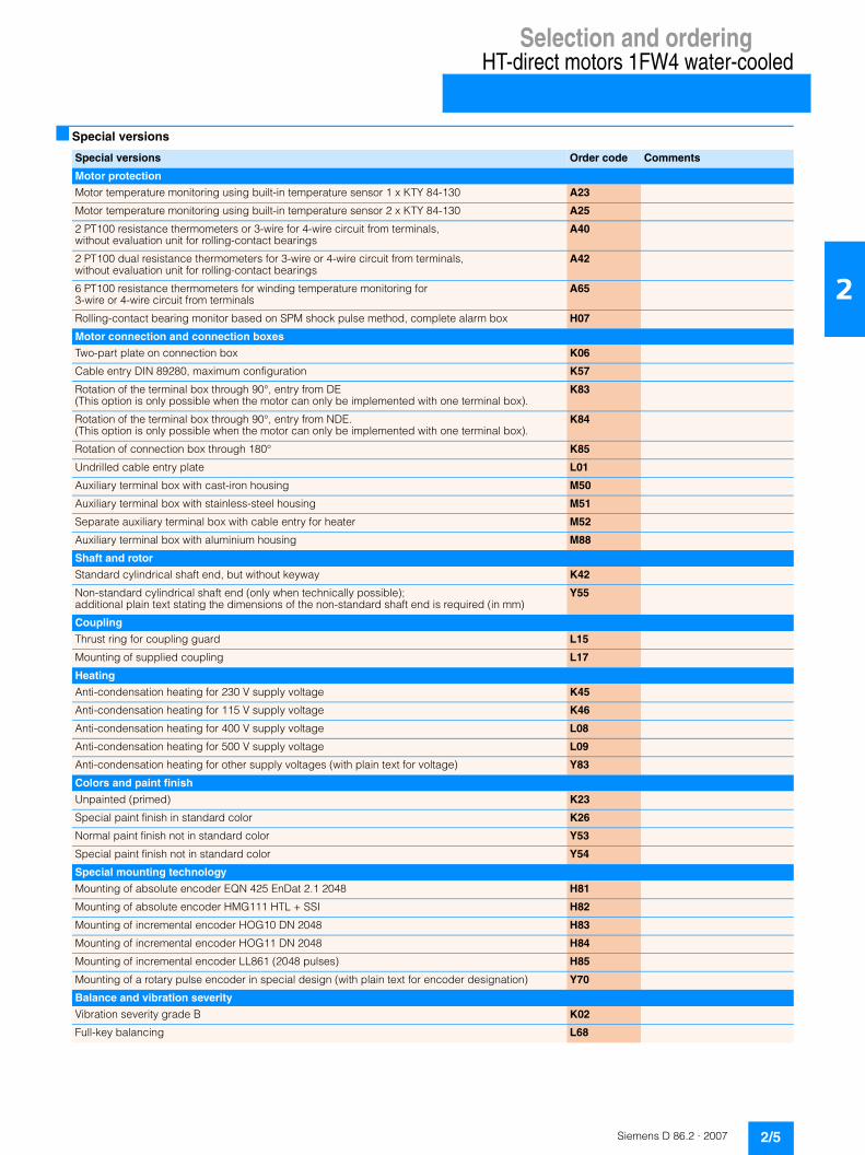
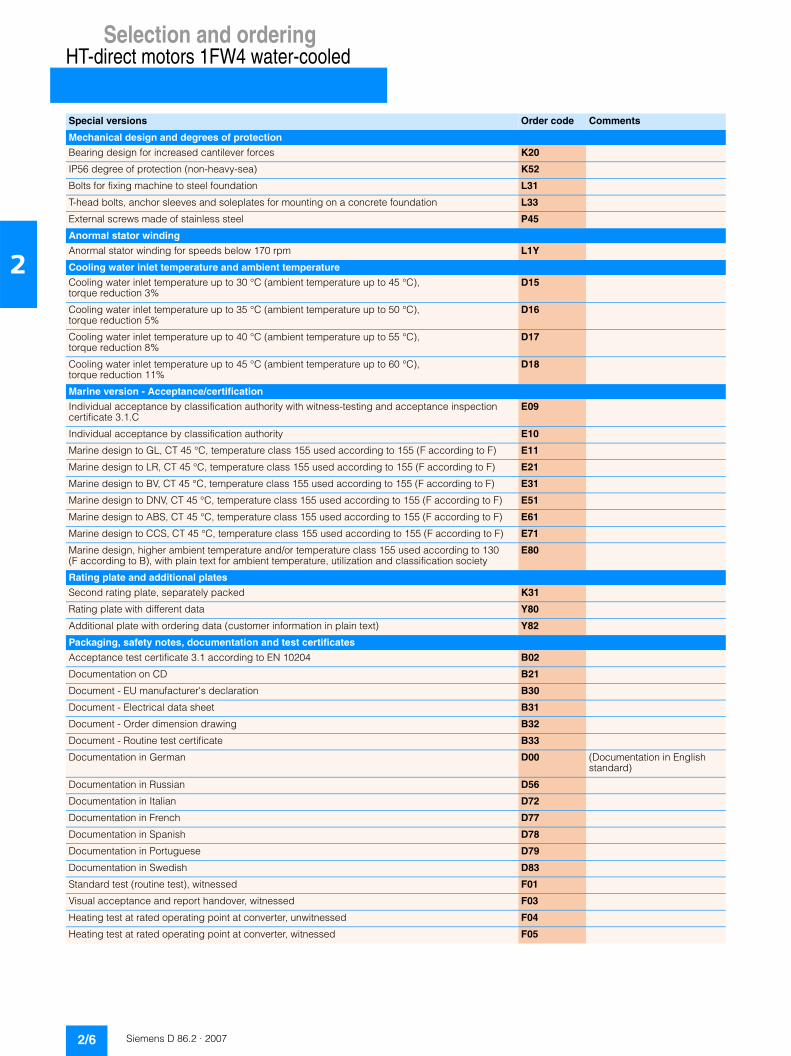
■ Special versions
Special versions Order code Comments
Motor protection
Motor temperature monitoring using built-in temperature sensor 1 x KTY 84-130 A23
Motor temperature monitoring using built-in temperature sensor 2 x KTY 84-130 A25
2 PT100 resistance thermometers or 3-wire for 4-wire circuit from terminals, without evaluation unit for rolling-contact bearings
A40
2 PT100 dual resistance thermometers for 3-wire or 4-wire circuit from terminals, without evaluation unit for rolling-contact bearings
A42
6 PT100 resistance thermometers for winding temperature monitoring for 3-wire or 4-wire circuit from terminals
A65
Rolling-contact bearing monitor based on SPM shock pulse method, complete alarm box H07
Motor connection and connection boxes
Two-part plate on connection box K06
Cable entry DIN 89280, maximum configuration K57
Rotation of the terminal box through 90°, entry from DE (This option is only possible when the motor can only be implemented with one terminal box).
K83
Rotation of the terminal box through 90°, entry from NDE. (This option is only possible when the motor can only be implemented with one terminal box).
K84
Rotation of connection box through 180° K85
Undrilled cable entry plate L01
Auxiliary terminal box with cast-iron housing M50
Auxiliary terminal box with stainless-steel housing M51
Separate auxiliary terminal box with cable entry for heater M52
Auxiliary terminal box with aluminium housing M88
Shaft and rotor
Standard cylindrical shaft end, but without keyway K42
Non-standard cylindrical shaft end (only when technically possible); additional plain text stating the dimensions of the non-standard shaft end is required (in mm)
Y55
Coupling
Thrust ring for coupling guard L15
Mounting of supplied coupling L17
Heating
Anti-condensation heating for 230 V supply voltage K45
Anti-condensation heating for 115 V supply voltage K46
Anti-condensation heating for 400 V supply voltage L08
Anti-condensation heating for 500 V supply voltage L09
Anti-condensation heating for other supply voltages (with plain text for voltage) Y83
Colors and paint finish
Unpainted (primed) K23
Special paint finish in standard color K26
Normal paint finish not in standard color Y53
Special paint finish not in standard color Y54
Special mounting technology
Mounting of absolute encoder EQN 425 EnDat 2.1 2048 H81
Mounting of absolute encoder HMG111 HTL + SSI H82
Mounting of incremental encoder HOG10 DN 2048 H83
Mounting of incremental encoder HOG11 DN 2048 H84
Mounting of incremental encoder LL861 (2048 pulses) H85
Mounting of a rotary pulse encoder in special design (with plain text for encoder designation) Y70
Balance and vibration severity
Vibration severity grade B K02
Full-key balancing L68
Selection and orderingHT-direct motors 1FW4 water-cooled
2/6 Siemens D 86.2 · 2007
2
Mechanical design and degrees of protection
Bearing design for increased cantilever forces K20
IP56 degree of protection (non-heavy-sea) K52
Bolts for fixing machine to steel foundation L31
T-head bolts, anchor sleeves and soleplates for mounting on a concrete foundation L33
External screws made of stainless steel P45
Anormal stator winding
Anormal stator winding for speeds below 170 rpm L1Y
Cooling water inlet temperature and ambient temperature
Cooling water inlet temperature up to 30 °C (ambient temperature up to 45 °C), torque reduction 3%
D15
Cooling water inlet temperature up to 35 °C (ambient temperature up to 50 °C), torque reduction 5%
D16
Cooling water inlet temperature up to 40 °C (ambient temperature up to 55 °C), torque reduction 8%
D17
Cooling water inlet temperature up to 45 °C (ambient temperature up to 60 °C), torque reduction 11%
D18
Marine version - Acceptance/certification
Individual acceptance by classification authority with witness-testing and acceptance inspection certificate 3.1.C
E09
Individual acceptance by classification authority E10
Marine design to GL, CT 45 °C, temperature class 155 used according to 155 (F according to F) E11
Marine design to LR, CT 45 °C, temperature class 155 used according to 155 (F according to F) E21
Marine design to BV, CT 45 °C, temperature class 155 used according to 155 (F according to F) E31
Marine design to DNV, CT 45 °C, temperature class 155 used according to 155 (F according to F) E51
Marine design to ABS, CT 45 °C, temperature class 155 used according to 155 (F according to F) E61
Marine design to CCS, CT 45 °C, temperature class 155 used according to 155 (F according to F) E71
Marine design, higher ambient temperature and/or temperature class 155 used according to 130 (F according to B), with plain text for ambient temperature, utilization and classification society
E80
Rating plate and additional plates
Second rating plate, separately packed K31
Rating plate with different data Y80
Additional plate with ordering data (customer information in plain text) Y82
Packaging, safety notes, documentation and test certificates
Acceptance test certificate 3.1 according to EN 10204 B02
Documentation on CD B21
Document - EU manufacturer's declaration B30
Document - Electrical data sheet B31
Document - Order dimension drawing B32
Document - Routine test certificate B33
Documentation in German D00 (Documentation in English standard)
Documentation in Russian D56
Documentation in Italian D72
Documentation in French D77
Documentation in Spanish D78
Documentation in Portuguese D79
Documentation in Swedish D83
Standard test (routine test), witnessed F01
Visual acceptance and report handover, witnessed F03
Heating test at rated operating point at converter, unwitnessed F04
Heating test at rated operating point at converter, witnessed F05
Special versions Order code Comments
Selection and orderingHT-direct motors 1FW4 water-cooled
2/7Siemens D 86.2 · 2007
2
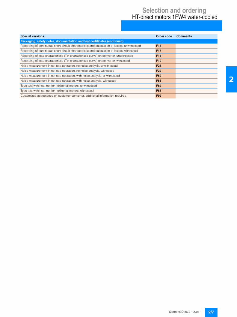
Packaging, safety notes, documentation and test certificates (continued)
Recording of continuous short-circuit characteristic and calculation of losses, unwitnessed F16
Recording of continuous short-circuit characteristic and calculation of losses, witnessed F17
Recording of load characteristic (T-n-characteristic curve) on converter, unwitnessed F18
Recording of load characteristic (T-n-characteristic curve) on converter, witnessed F19
Noise measurement in no-load operation, no noise analysis, unwitnessed F28
Noise measurement in no-load operation, no noise analysis, witnessed F29
Noise measurement in no-load operation, with noise analysis, unwitnessed F62
Noise measurement in no-load operation, with noise analysis, witnessed F63
Type test with heat run for horizontal motors, unwitnessed F82
Type test with heat run for horizontal motors, witnessed F83
Customized acceptance on customer converter, additional information required F99
Special versions Order code Comments

Selection and orderingHT-direct motors 1FW4 water-cooled
2/8 Siemens D 86.2 · 2007
2
■ Dimension drawings
Type Dimensions
A AA AB AD 1) B BA BB BC BE C H HA HD K L
1FW4401 750 150 900 400 1120 260 1365 155 880 254 400 30 1180 35 1880
1FW4403
1FW4405
1FW4407
1FW4451 850 180 1030 400 1250 265 1515 165 975 280 450 30 1280 42 2090
1FW4453
1FW4455
1FW4503 950 180 1130 400 1400 300 1624 250 935 280 500 40 1385 42 2265
1FW4505
1FW4507 950 180 1130 400 1500 300 1782 135 628 315 500 40 1385 42 2415
1FW4508
Type Dimensions for shaft extension according to DIN 748 “short” Dimensions of cooling water connection 2)
D E F GA W WA WB
1FW4401 150 200 36 158 G3/4" 50 780
1FW4403
1FW4405
1FW4407
1FW4451 170 240 40 179 G1" 63 1175
1FW4453
1FW4455
1FW4503 190 280 45 200 G11/2" 85 1260
1FW4505
1FW4507 190 280 45 200 G11/2" 40 1440
1FW4508
BB
D
BC
BC
G_
D0
86
_X
X_
00
01
5a
BA K K AA
A
E
H
HD
HA
WB
W W
BE
L
F
GA
WA
AB
AD
1) For 1XB1 631 terminal box.2) The cooling water connection is available on both sides (RHS and LHS of
motor).
Selection and orderingHT-direct motors 1FW4 water-cooled
2/9Siemens D 86.2 · 2007
2
■ Further information
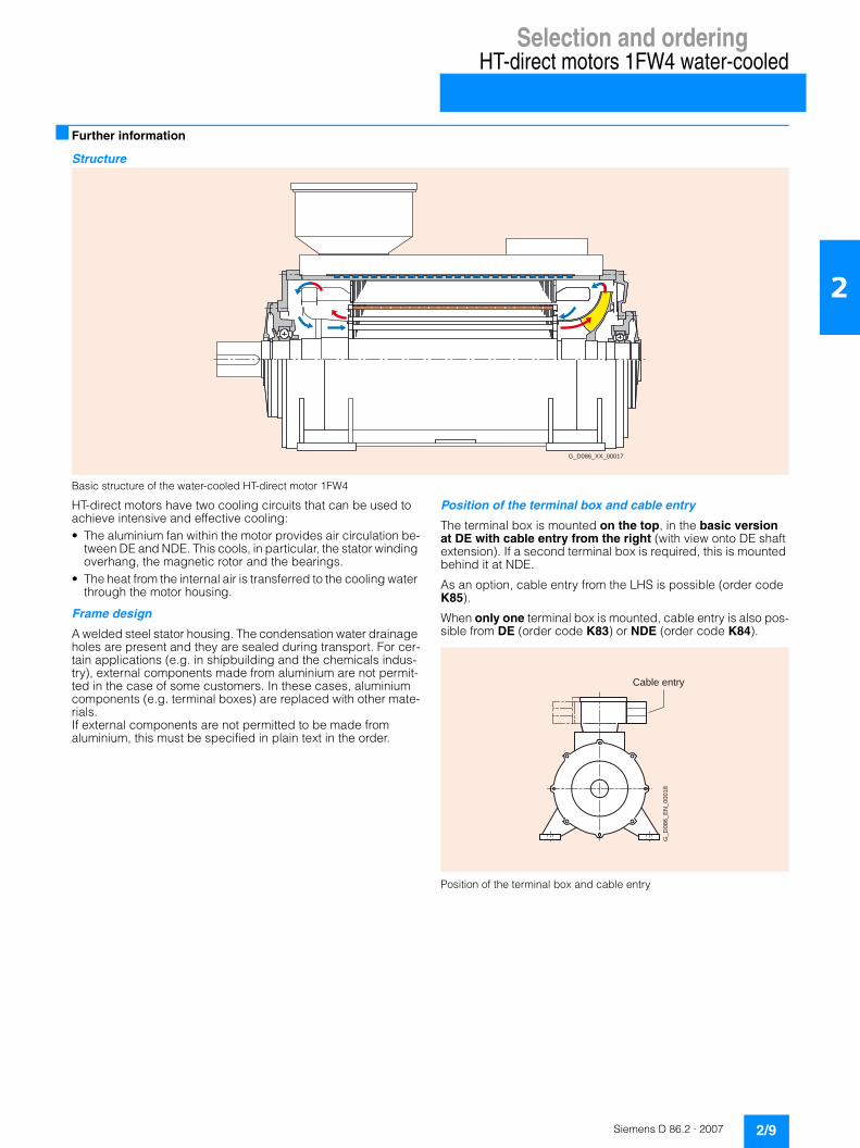
Structure
Basic structure of the water-cooled HT-direct motor 1FW4
HT-direct motors have two cooling circuits that can be used to achieve intensive and effective cooling: • The aluminium fan within the motor provides air circulation be-
tween DE and NDE. This cools, in particular, the stator winding overhang, the magnetic rotor and the bearings.
• The heat from the internal air is transferred to the cooling water through the motor housing.
Frame design
A welded steel stator housing. The condensation water drainage holes are present and they are sealed during transport. For cer-tain applications (e.g. in shipbuilding and the chemicals indus-try), external components made from aluminium are not permit-ted in the case of some customers. In these cases, aluminium components (e.g. terminal boxes) are replaced with other mate-rials. If external components are not permitted to be made from aluminium, this must be specified in plain text in the order.
Position of the terminal box and cable entry
The terminal box is mounted on the top, in the basic version at DE with cable entry from the right (with view onto DE shaft extension). If a second terminal box is required, this is mounted behind it at NDE.
As an option, cable entry from the LHS is possible (order code K85).
When only one terminal box is mounted, cable entry is also pos-sible from DE (order code K83) or NDE (order code K84).
Position of the terminal box and cable entry
G_D086_XX_00017
Cable entry
G_
D0
86
_E
N_
00
01
8
Selection and orderingHT-direct motors 1FW4 water-cooled
2/10 Siemens D 86.2 · 2007
2
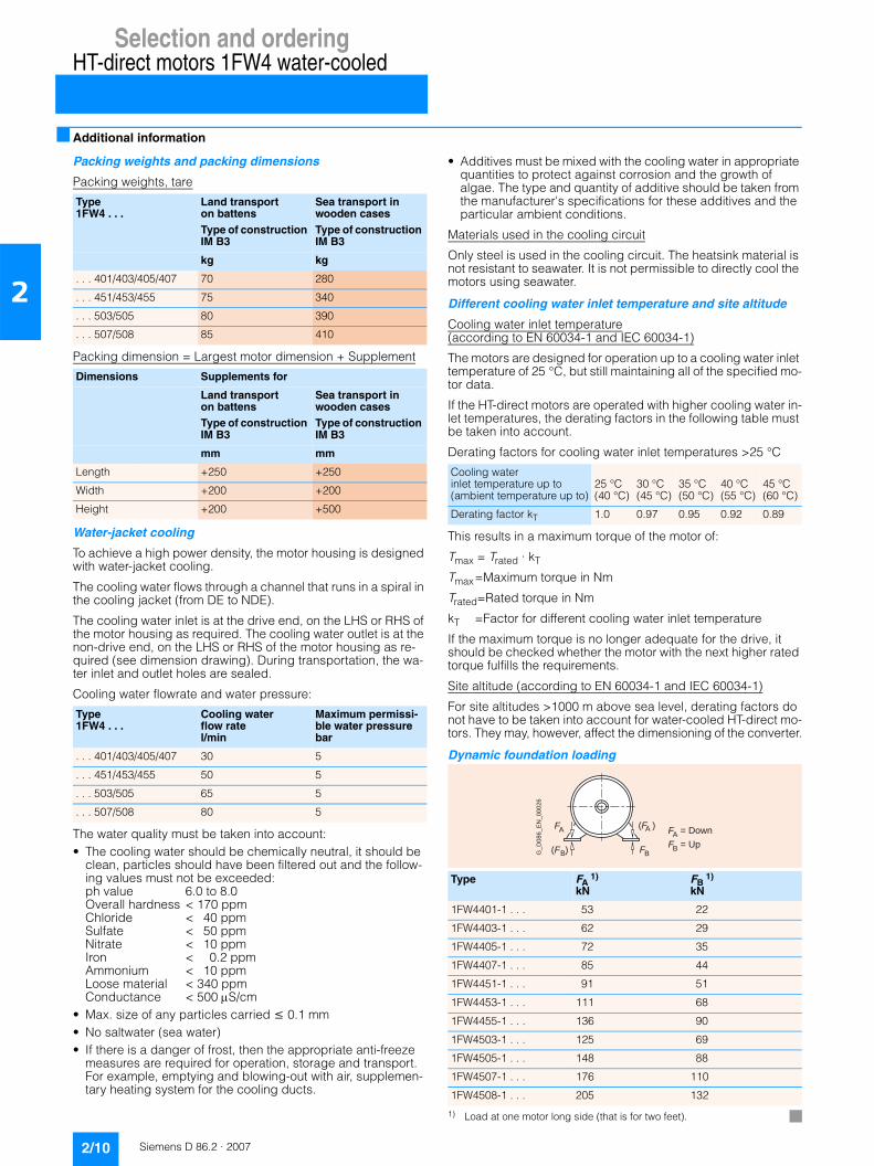
■ Additional information
Packing weights and packing dimensions
Packing weights, tare
Packing dimension = Largest motor dimension + Supplement
Water-jacket cooling
To achieve a high power density, the motor housing is designed with water-jacket cooling.
The cooling water flows through a channel that runs in a spiral in the cooling jacket (from DE to NDE).
The cooling water inlet is at the drive end, on the LHS or RHS of the motor housing as required. The cooling water outlet is at the non-drive end, on the LHS or RHS of the motor housing as re-quired (see dimension drawing). During transportation, the wa-ter inlet and outlet holes are sealed.
Cooling water flowrate and water pressure:
The water quality must be taken into account:• The cooling water should be chemically neutral, it should be
clean, particles should have been filtered out and the follow-ing values must not be exceeded:ph value 6.0 to 8.0 Overall hardness < 170 ppm Chloride < 40 ppm Sulfate < 50 ppm Nitrate < 10 ppm Iron < 0.2 ppm Ammonium < 10 ppm Loose material < 340 ppm Conductance < 500 μS/cm
• Max. size of any particles carried ≤ 0.1 mm• No saltwater (sea water)• If there is a danger of frost, then the appropriate anti-freeze
measures are required for operation, storage and transport. For example, emptying and blowing-out with air, supplemen-tary heating system for the cooling ducts.
• Additives must be mixed with the cooling water in appropriate quantities to protect against corrosion and the growth of algae. The type and quantity of additive should be taken from the manufacturer's specifications for these additives and the particular ambient conditions.
Materials used in the cooling circuit
Only steel is used in the cooling circuit. The heatsink material is not resistant to seawater. It is not permissible to directly cool the motors using seawater.
Different cooling water inlet temperature and site altitude
Cooling water inlet temperature(according to EN 60034-1 and IEC 60034-1)
The motors are designed for operation up to a cooling water inlet temperature of 25 °C, but still maintaining all of the specified mo-tor data.
If the HT-direct motors are operated with higher cooling water in-let temperatures, the derating factors in the following table must be taken into account.
Derating factors for cooling water inlet temperatures >25 °C
This results in a maximum torque of the motor of:
Tmax = Trated · kT
Tmax=Maximum torque in Nm
Trated=Rated torque in Nm
kT =Factor for different cooling water inlet temperature
If the maximum torque is no longer adequate for the drive, it should be checked whether the motor with the next higher rated torque fulfills the requirements.
Site altitude (according to EN 60034-1 and IEC 60034-1)
For site altitudes >1000 m above sea level, derating factors do not have to be taken into account for water-cooled HT-direct mo-tors. They may, however, affect the dimensioning of the converter.
Dynamic foundation loading
1) Load at one motor long side (that is for two feet).
Type 1FW4 . . .
Land transport on battensType of construction IM B3
Sea transport in wooden casesType of construction IM B3
kg kg
. . . 401/403/405/407 70 280
. . . 451/453/455 75 340
. . . 503/505 80 390
. . . 507/508 85 410
Dimensions Supplements for
Land transport on battensType of construction IM B3
Sea transport in wooden casesType of construction IM B3
mm mm
Length +250 +250
Width +200 +200
Height +200 +500
Type 1FW4 . . .
Cooling water flow ratel/min
Maximum permissi-ble water pressure bar
. . . 401/403/405/407 30 5
. . . 451/453/455 50 5
. . . 503/505 65 5
. . . 507/508 80 5
Cooling water inlet temperature up to (ambient temperature up to)
25 °C (40 °C)
30 °C (45 °C)
35 °C (50 °C)
40 °C (55 °C)
45 °C (60 °C)
Derating factor kT 1.0 0.97 0.95 0.92 0.89
Type FA 1)
kNFB
1)
kN
1FW4401-1 . . . 53 22
1FW4403-1 . . . 62 29
1FW4405-1 . . . 72 35
1FW4407-1 . . . 85 44
1FW4451-1 . . . 91 51
1FW4453-1 . . . 111 68
1FW4455-1 . . . 136 90
1FW4503-1 . . . 125 69
1FW4505-1 . . . 148 88
1FW4507-1 . . . 176 110
1FW4508-1 . . . 205 132
(F )A
FB(F )B
FA
G_
D0
86
_E
N_
00
02
6
F = DownA
F = UpB

Siemens D 86.2 · 2007
3/2 Overview3/2 Benefits3/3 Selection and ordering data3/5 Special versions3/8 Dimension drawings3/9 Additional information
Selection and orderingHT-direct motors 1FW4air-cooled

Selection and orderingHT-direct motors 1FW4 air-cooled
3/2 Siemens D 86.2 · 2007
3
■ Overview
The motors are designed for the following rated voltages:• 690 V*/50 Hz• 400 V*/50 Hz• 460 V*/60 Hz
Ambient temperature: -20 °C to +40 °CSite altitude: Up to 1000 m above sea levelAt higher ambient temperatures and site altitudes above 1000 m, a motor Order No. must be selected in accordance with the derating factors (see Page 3/12). The order codes for the cooling-water inlet temperature (see Page 3/6) and site altitude over 1000 m (see Page 3/6) must also be specified in the order.
Degree of protection: IP55
Cooling method: IC416
Type of construction: IM B3
Overview of torques and outputsin accordance with the rated speed
■ Benefits
The well-proven cooling principle of the H-compact motors forms the basis for the air-cooled HT-direct motors. The constant cooling air flow independent of the motor speed from the external fan assembly mounted axially at the non-drive end ensures intensive, even motor cooling which is the basis of a long lifetime.
Rated speed rpm
Max. rated torque Nm
Max. rated output kW
200 23000 481
300 22250 699
400 21500 900
500 20750 1086
600 20000 1256
800 14100 1181

Selection and orderingHT-direct motors 1FW4 air-cooled
3/3Siemens D 86.2 · 2007
3
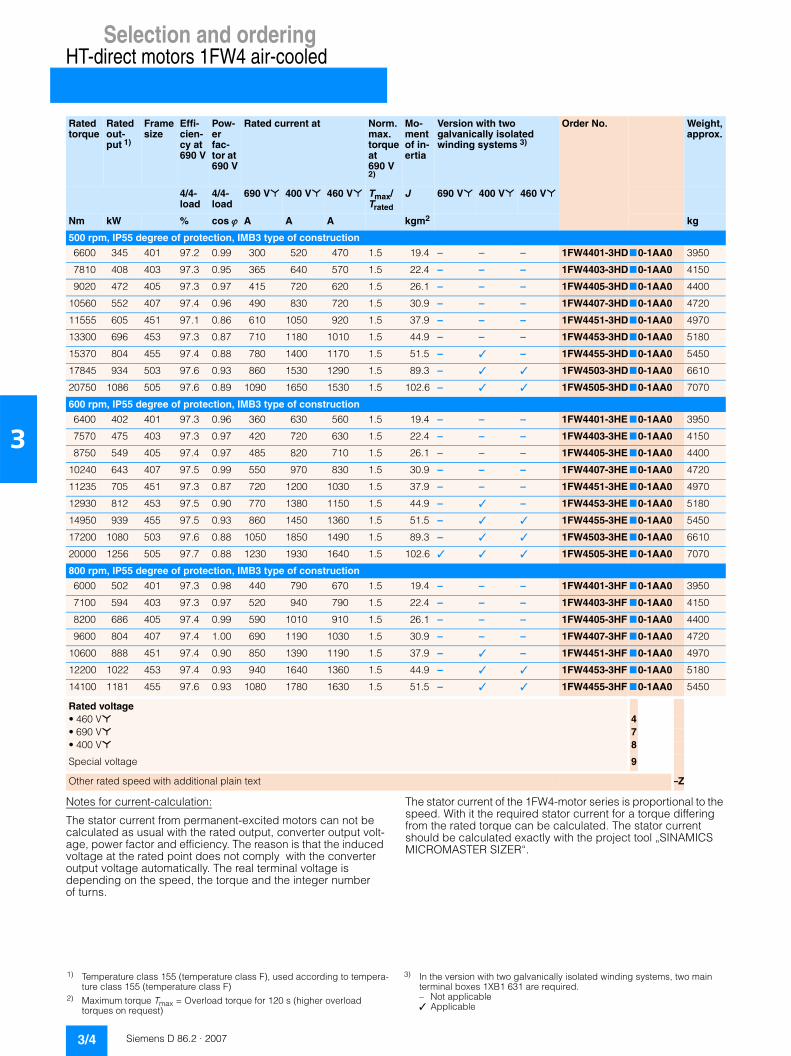
■ Selection and ordering data
Rated torque
Rated out-put 1)
Frame size
Effi-cien-cy at 690 V
Pow-er fac-tor at 690 V
Rated current at Norm. max. torque at 690 V 2)
Mo-ment of in-ertia
Version with two galvanically isolated winding systems 3)
Order No. Weight, approx.
4/4- load
4/4- load
690 V* 400 V* 460 V* Tmax/Trated
J 690 V* 400 V* 460 V*
Nm kW % cos ϕ A A A kgm2 kg
200 rpm, IP55 degree of protection, IMB3 type of construction
7200 150 401 95.4 0.94 140 255 215 1.5 19.4 – – – 1FW4401-3HA70-1AA0 3950
8520 178 403 95.6 0.92 174 280 250 1.5 22.4 – – – 1FW4403-3HA70-1AA0 4150
9840 206 405 95.8 0.93 192 335 300 1.5 26.1 – – – 1FW4405-3HA70-1AA0 4400
11520 241 407 96.0 0.94 220 380 355 1.5 30.9 – – – 1FW4407-3HA70-1AA0 4720
12510 262 451 94.7 0.85 285 495 440 1.5 37.9 – – – 1FW4451-3HA70-1AA0 4970
14395 301 453 95.1 0.86 315 540 475 1.5 44.9 – – – 1FW4453-3HA70-1AA0 5180
16640 348 455 95.4 0.86 375 630 540 1.5 51.5 – – – 1FW4455-3HA70-1AA0 5450
19780 414 503 96.1 0.87 420 700 600 1.5 89.3 – – – 1FW4503-3HA70-1AA0 6610
23000 481 505 96.3 0.89 470 840 700 1.5 102.6 – – – 1FW4505-3HA70-1AA0 7070
300 rpm, IP55 degree of protection, IMB3 type of construction
7000 219 401 96.5 0.96 198 345 320 1.5 19.4 – – – 1FW4401-3HB70-1AA0 3950
8280 260 403 96.5 0.97 230 415 360 1.5 22.4 – – – 1FW4403-3HB70-1AA0 4150
9565 300 405 96.7 0.97 265 475 435 1.5 26.1 – – – 1FW4405-3HB70-1AA0 4400
11200 351 407 96.8 0.94 320 570 475 1.5 30.9 – – – 1FW4407-3HB70-1AA0 4720
12190 382 451 96.1 0.86 385 700 560 1.5 37.9 – – – 1FW4451-3HB70-1AA0 4970
14030 440 453 96.4 0.86 465 830 680 1.5 44.9 – – – 1FW4453-3HB70-1AA0 5180
16215 509 455 96.5 0.87 520 920 820 1.5 51.5 – – – 1FW4455-3HB70-1AA0 5450
19135 601 503 97.0 0.88 580 1020 910 1.5 89.3 – – – 1FW4503-3HB70-1AA0 6610
22250 699 505 97.1 0.88 680 1170 1020 1.5 102.6 – – – 1FW4505-3HB70-1AA0 7070
400 rpm, IP55 degree of protection, IMB3 type of construction
6800 284 401 96.9 0.98 250 445 410 1.5 19.4 – – – 1FW4401-3HC70-1AA0 3950
8050 337 403 97.1 0.97 295 530 480 1.5 22.4 – – – 1FW4403-3HC70-1AA0 4150
9290 389 405 97.1 0.94 365 640 510 1.5 26.1 – – – 1FW4405-3HC70-1AA0 4400
10880 455 407 97.2 0.94 420 720 630 1.5 30.9 – – – 1FW4407-3HC70-1AA0 4720
11870 497 451 96.7 0.86 540 840 750 1.5 37.9 – – – 1FW4451-3HC70-1AA0 4970
13665 572 453 96.9 0.87 600 1040 910 1.5 44.9 – – – 1FW4453-3HC70-1AA0 5180
15790 661 455 97.1 0.87 650 1200 1030 1.5 51.5 – – – 1FW4455-3HC70-1AA0 5450
18490 774 503 97.4 0.91 720 1320 1130 1.5 89.3 – ✓ – 1FW4503-3HC70-1AA0 6610
21500 900 505 97.5 0.88 880 1580 1320 1.5 102.6 – ✓ ✓ 1FW4505-3HC70-1AA0 7070
Rated voltage• 460 V* 4• 690 V* 7• 400 V* 8
Special voltage 9
Other rated speed with additional plain text –Z
1) Temperature class 155 (temperature class F), used according to tempera-ture class 155 (temperature class F)
2) Maximum torque Tmax = Overload torque for 120 s (higher overload torques on request)
3) In the version with two galvanically isolated winding systems, two main terminal boxes 1XB1 631 are required.– Not applicable✓ Applicable
Selection and orderingHT-direct motors 1FW4 air-cooled
3/4 Siemens D 86.2 · 2007
3
Notes for current-calculation:
The stator current from permanent-excited motors can not be calculated as usual with the rated output, converter output volt-age, power factor and efficiency. The reason is that the induced voltage at the rated point does not comply with the converter output voltage automatically. The real terminal voltage is depending on the speed, the torque and the integer number of turns.
The stator current of the 1FW4-motor series is proportional to the speed. With it the required stator current for a torque differing from the rated torque can be calculated. The stator current should be calculated exactly with the project tool „SINAMICS MICROMASTER SIZER“.
Rated torque
Rated out-put 1)
Frame size
Effi-cien-cy at 690 V
Pow-er fac-tor at 690 V
Rated current at Norm. max. torque at 690 V 2)
Mo-ment of in-ertia
Version with two galvanically isolated winding systems 3)
Order No. Weight, approx.
4/4- load
4/4- load
690 V* 400 V* 460 V* Tmax/Trated
J 690 V* 400 V* 460 V*
Nm kW % cos ϕ A A A kgm2 kg
500 rpm, IP55 degree of protection, IMB3 type of construction
6600 345 401 97.2 0.99 300 520 470 1.5 19.4 – – – 1FW4401-3HD70-1AA0 3950
7810 408 403 97.3 0.95 365 640 570 1.5 22.4 – – – 1FW4403-3HD70-1AA0 4150
9020 472 405 97.3 0.97 415 720 620 1.5 26.1 – – – 1FW4405-3HD70-1AA0 4400
10560 552 407 97.4 0.96 490 830 720 1.5 30.9 – – – 1FW4407-3HD70-1AA0 4720
11555 605 451 97.1 0.86 610 1050 920 1.5 37.9 – – – 1FW4451-3HD70-1AA0 4970
13300 696 453 97.3 0.87 710 1180 1010 1.5 44.9 – – – 1FW4453-3HD70-1AA0 5180
15370 804 455 97.4 0.88 780 1400 1170 1.5 51.5 – ✓ – 1FW4455-3HD70-1AA0 5450
17845 934 503 97.6 0.93 860 1530 1290 1.5 89.3 – ✓ ✓ 1FW4503-3HD70-1AA0 6610
20750 1086 505 97.6 0.89 1090 1650 1530 1.5 102.6 – ✓ ✓ 1FW4505-3HD70-1AA0 7070
600 rpm, IP55 degree of protection, IMB3 type of construction
6400 402 401 97.3 0.96 360 630 560 1.5 19.4 – – – 1FW4401-3HE 70-1AA0 3950
7570 475 403 97.3 0.97 420 720 630 1.5 22.4 – – – 1FW4403-3HE 70-1AA0 4150
8750 549 405 97.4 0.97 485 820 710 1.5 26.1 – – – 1FW4405-3HE 70-1AA0 4400
10240 643 407 97.5 0.99 550 970 830 1.5 30.9 – – – 1FW4407-3HE 70-1AA0 4720
11235 705 451 97.3 0.87 720 1200 1030 1.5 37.9 – – – 1FW4451-3HE 70-1AA0 4970
12930 812 453 97.5 0.90 770 1380 1150 1.5 44.9 – ✓ – 1FW4453-3HE 70-1AA0 5180
14950 939 455 97.5 0.93 860 1450 1360 1.5 51.5 – ✓ ✓ 1FW4455-3HE 70-1AA0 5450
17200 1080 503 97.6 0.88 1050 1850 1490 1.5 89.3 – ✓ ✓ 1FW4503-3HE 70-1AA0 6610
20000 1256 505 97.7 0.88 1230 1930 1640 1.5 102.6 ✓ ✓ ✓ 1FW4505-3HE 70-1AA0 7070
800 rpm, IP55 degree of protection, IMB3 type of construction
6000 502 401 97.3 0.98 440 790 670 1.5 19.4 – – – 1FW4401-3HF 70-1AA0 3950
7100 594 403 97.3 0.97 520 940 790 1.5 22.4 – – – 1FW4403-3HF 70-1AA0 4150
8200 686 405 97.4 0.99 590 1010 910 1.5 26.1 – – – 1FW4405-3HF 70-1AA0 4400
9600 804 407 97.4 1.00 690 1190 1030 1.5 30.9 – – – 1FW4407-3HF 70-1AA0 4720
10600 888 451 97.4 0.90 850 1390 1190 1.5 37.9 – ✓ – 1FW4451-3HF 70-1AA0 4970
12200 1022 453 97.4 0.93 940 1640 1360 1.5 44.9 – ✓ ✓ 1FW4453-3HF 70-1AA0 5180
14100 1181 455 97.6 0.93 1080 1780 1630 1.5 51.5 – ✓ ✓ 1FW4455-3HF 70-1AA0 5450
Rated voltage• 460 V* 4• 690 V* 7• 400 V* 8
Special voltage 9
Other rated speed with additional plain text –Z
1) Temperature class 155 (temperature class F), used according to tempera-ture class 155 (temperature class F)
2) Maximum torque Tmax = Overload torque for 120 s (higher overload torques on request)
3) In the version with two galvanically isolated winding systems, two main terminal boxes 1XB1 631 are required.– Not applicable✓ Applicable
Selection and orderingHT-direct motors 1FW4 air-cooled
3/5Siemens D 86.2 · 2007
3
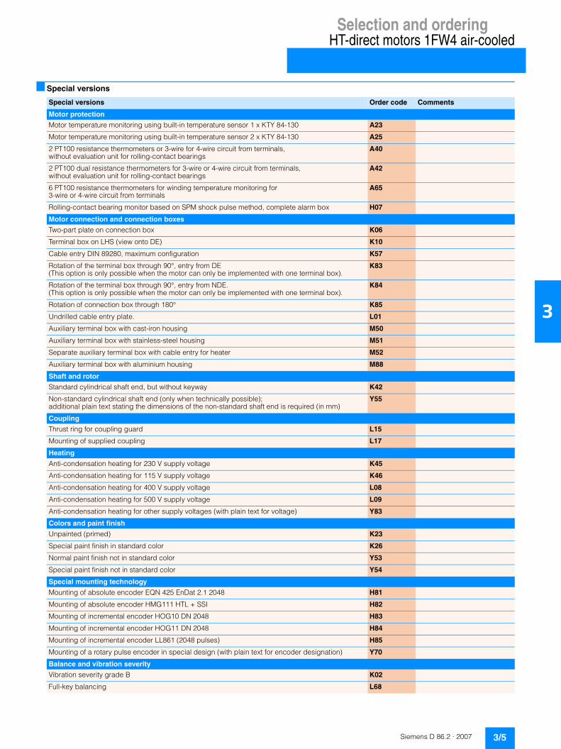
■ Special versions
Special versions Order code Comments
Motor protection
Motor temperature monitoring using built-in temperature sensor 1 x KTY 84-130 A23
Motor temperature monitoring using built-in temperature sensor 2 x KTY 84-130 A25
2 PT100 resistance thermometers or 3-wire for 4-wire circuit from terminals, without evaluation unit for rolling-contact bearings
A40
2 PT100 dual resistance thermometers for 3-wire or 4-wire circuit from terminals, without evaluation unit for rolling-contact bearings
A42
6 PT100 resistance thermometers for winding temperature monitoring for 3-wire or 4-wire circuit from terminals
A65
Rolling-contact bearing monitor based on SPM shock pulse method, complete alarm box H07
Motor connection and connection boxes
Two-part plate on connection box K06
Terminal box on LHS (view onto DE) K10
Cable entry DIN 89280, maximum configuration K57
Rotation of the terminal box through 90°, entry from DE (This option is only possible when the motor can only be implemented with one terminal box).
K83
Rotation of the terminal box through 90°, entry from NDE. (This option is only possible when the motor can only be implemented with one terminal box).
K84
Rotation of connection box through 180° K85
Undrilled cable entry plate. L01
Auxiliary terminal box with cast-iron housing M50
Auxiliary terminal box with stainless-steel housing M51
Separate auxiliary terminal box with cable entry for heater M52
Auxiliary terminal box with aluminium housing M88
Shaft and rotor
Standard cylindrical shaft end, but without keyway K42
Non-standard cylindrical shaft end (only when technically possible); additional plain text stating the dimensions of the non-standard shaft end is required (in mm)
Y55
Coupling
Thrust ring for coupling guard L15
Mounting of supplied coupling L17
Heating
Anti-condensation heating for 230 V supply voltage K45
Anti-condensation heating for 115 V supply voltage K46
Anti-condensation heating for 400 V supply voltage L08
Anti-condensation heating for 500 V supply voltage L09
Anti-condensation heating for other supply voltages (with plain text for voltage) Y83
Colors and paint finish
Unpainted (primed) K23
Special paint finish in standard color K26
Normal paint finish not in standard color Y53
Special paint finish not in standard color Y54
Special mounting technology
Mounting of absolute encoder EQN 425 EnDat 2.1 2048 H81
Mounting of absolute encoder HMG111 HTL + SSI H82
Mounting of incremental encoder HOG10 DN 2048 H83
Mounting of incremental encoder HOG11 DN 2048 H84
Mounting of incremental encoder LL861 (2048 pulses) H85
Mounting of a rotary pulse encoder in special design (with plain text for encoder designation) Y70
Balance and vibration severity
Vibration severity grade B K02
Full-key balancing L68

Selection and orderingHT-direct motors 1FW4 air-cooled
3/6 Siemens D 86.2 · 2007
3
Mechanical design and degrees of protection
Bearing design for increased cantilever forces K20
IP56 degree of protection (non-heavy-sea) K52
Bolts for fixing machine to steel foundation L31
T-head bolts, anchor sleeves and soleplates for mounting on a concrete foundation L33
External screws made of stainless steel P45
Anormal stator winding
Anormal stator winding for speeds below 170 rpm L1Y
Ambient temperature and site altitude
Coolant temperature –50 to +40 °C D02
Coolant temperature –40 to +40 °C D03
Coolant temperature –30 to +40 °C D04
Site altitude up to 1500 m D06
Site altitude up to 2000 m D07
Site altitude up to 2500 m D08
Site altitude up to 3000 m D09
Coolant temperature up to 45 °C, torque reduction of 4% D11
Coolant temperature up to 50 °C, torque reduction of 8% D12
Coolant temperature up to 55 °C, torque reduction of 13% D13
Coolant temperature up to 60 °C, torque reduction of 18% D14
Marine version - Acceptance/certification
Individual acceptance by classification authority with witness-testing and acceptance inspection certificate 3.1.C
E09
Individual acceptance by classification authority E10
Marine design to GL, CT 45 °C, temperature class 155 used according to 155 (F according to F) E11
Marine design to LR, CT 45 °C, temperature class 155 used according to 155 (F according to F) E21
Marine design to BV, CT 45 °C, temperature class 155 used according to 155 (F according to F) E31
Marine design to DNV, CT 45 °C, temperature class 155 used according to 155 (F according to F) E51
Marine design to ABS, CT 45 °C, temperature class 155 used according to 155 (F according to F) E61
Marine design to CCS, CT 45 °C, temperature class 155 used according to 155 (F according to F) E71
Marine design, higher ambient temperature and/or temperature class 155 used according to 130 (F according to B), with plain text for ambient temperature, utilization and classification society
E80
Rating plate and additional plates
Second rating plate, separately packed K31
Rating plate with different data Y80
Additional plate with ordering data (customer information in plain text) Y82
Packaging, safety notes, documentation and test certificates
Acceptance test certificate 3.1 according to EN 10204 B02
Documentation on CD B21
Document - EU manufacturer's declaration B30
Document - Electrical data sheet B31
Document - Order dimension drawing B32
Document - Routine test certificate B33
Documentation in German D00 (Documentation in English standard)
Documentation in Russian D56
Documentation in Italian D72
Documentation in French D77
Documentation in Spanish D78
Documentation in Portuguese D79
Documentation in Swedish D83
Special versions Order code Comments

Selection and orderingHT-direct motors 1FW4 air-cooled
3/7Siemens D 86.2 · 2007
3
Packaging, safety notes, documentation and test certificates (continued)
Standard test (routine test), witnessed F01
Visual acceptance and report handover, witnessed F03
Temperature-rise test, unwitnessed F04
Temperature-rise test, witnessed F05
Recording of continuous short-circuit characteristic and calculation of losses, unwitnessed F16
Recording of continuous short-circuit characteristic and calculation of losses, witnessed F17
Recording of load characteristic (T-n-characteristic curve) on converter, unwitnessed F18
Recording of load characteristic (T-n-characteristic curve) on converter, witnessed F19
Noise measurement in no-load operation, no noise analysis, unwitnessed F28
Noise measurement in no-load operation, no noise analysis, witnessed F29
Noise measurement in no-load operation, with noise analysis, unwitnessed F62
Noise measurement in no-load operation, with noise analysis, witnessed F63
Type test with heat run for horizontal motors, unwitnessed F82
Type test with heat run for horizontal motors, witnessed F83
Customized acceptance on customer converter, additional information required F99
Special versions Order code Comments

Selection and orderingHT-direct motors 1FW4 air-cooled
3/8 Siemens D 86.2 · 2007
3
■ Dimension drawings
Type Dimensions
A AA AB AC AD 1) AG 1) B BA BB BC BE C H HA HB 1) HD K L
1FW4401 750 150 900 855 865 775 1120 220 1320 201 745 254 400 35 440 1020 35 2470
1FW4403
1FW4405
1FW4407
1FW4451 850 180 1030 955 910 820 1250 260 1490 220 865 280 450 42 530 1110 42 2880
1FW4453
1FW4455
1FW4503 950 180 1130 1075 960 870 1320 260 1560 220 880 315 500 42 630 1210 42 3120
1FW4505
Type Dimensions for shaft extension according to DIN 748 “short”
D E F GA
1FW4401 150 200 36 158
1FW4403
1FW4405
1FW4407
1FW4451 170 240 40 179
1FW4453
1FW4455
1FW4503 190 280 45 200
1FW4505
AD
BB
D
BC
L
G_
D0
86
_X
X_
00
01
6
AC
E
BC
K
BA
HAH
A
AB
K AA
AG
HB
HD
BE
F
GA
1) For 1XB1 631 terminal box.
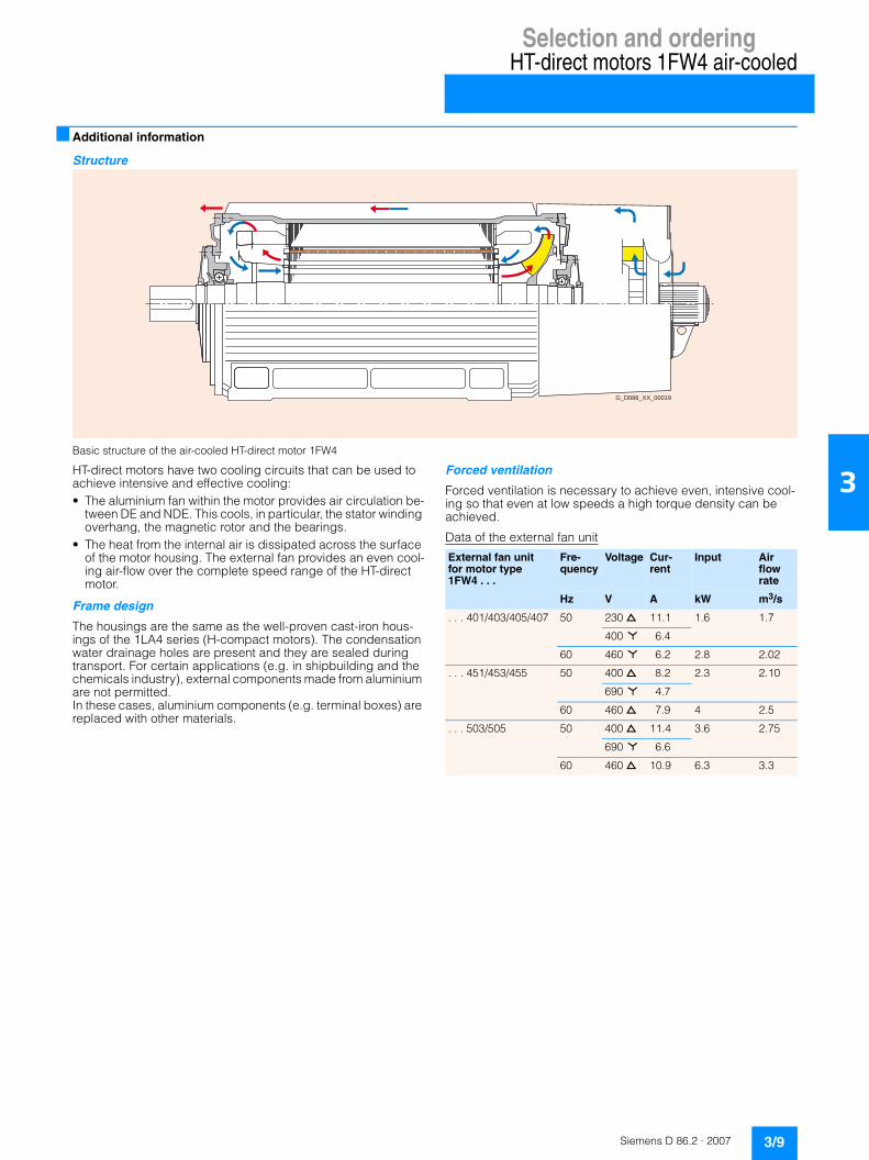
Selection and orderingHT-direct motors 1FW4 air-cooled
3/9Siemens D 86.2 · 2007
3
■ Additional information
Structure
Basic structure of the air-cooled HT-direct motor 1FW4
HT-direct motors have two cooling circuits that can be used to achieve intensive and effective cooling: • The aluminium fan within the motor provides air circulation be-
tween DE and NDE. This cools, in particular, the stator winding overhang, the magnetic rotor and the bearings.
• The heat from the internal air is dissipated across the surface of the motor housing. The external fan provides an even cool-ing air-flow over the complete speed range of the HT-direct motor.
Frame design
The housings are the same as the well-proven cast-iron hous-ings of the 1LA4 series (H-compact motors). The condensation water drainage holes are present and they are sealed during transport. For certain applications (e.g. in shipbuilding and the chemicals industry), external components made from aluminium are not permitted. In these cases, aluminium components (e.g. terminal boxes) are replaced with other materials.
Forced ventilation
Forced ventilation is necessary to achieve even, intensive cool-ing so that even at low speeds a high torque density can be achieved.
Data of the external fan unit
G_D086_XX_00019
External fan unit for motor type 1FW4 . . .
Fre-quency
Voltage Cur-rent
Input Air flow rate
Hz V A kW m3/s
. . . 401/403/405/407 50 230 d 11.1 1.6 1.7
400 * 6.4
60 460 * 6.2 2.8 2.02
. . . 451/453/455 50 400 d 8.2 2.3 2.10
690 * 4.7
60 460 d 7.9 4 2.5
. . . 503/505 50 400 d 11.4 3.6 2.75
690 * 6.6
60 460 d 10.9 6.3 3.3
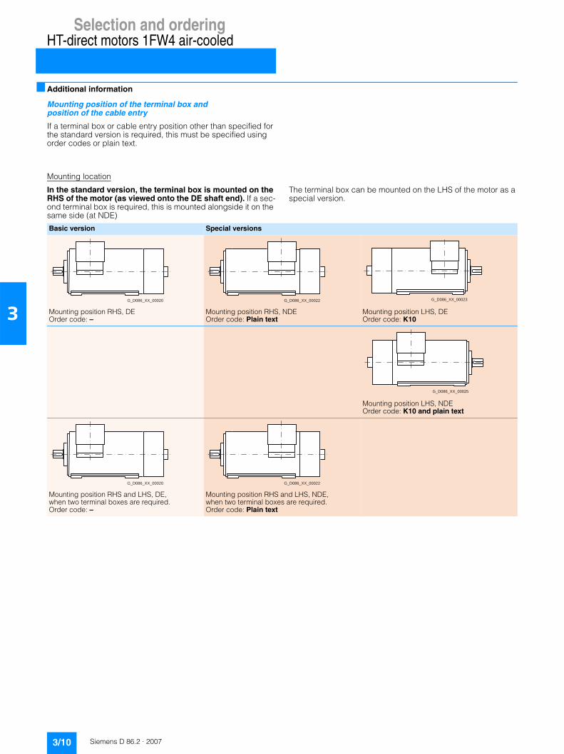
Selection and orderingHT-direct motors 1FW4 air-cooled
3/10 Siemens D 86.2 · 2007
3
■ Additional information
Mounting position of the terminal box and position of the cable entry
If a terminal box or cable entry position other than specified for the standard version is required, this must be specified using order codes or plain text.
Mounting location
In the standard version, the terminal box is mounted on the RHS of the motor (as viewed onto the DE shaft end). If a sec-ond terminal box is required, this is mounted alongside it on the same side (at NDE)
The terminal box can be mounted on the LHS of the motor as a special version.
Basic version Special versions
Mounting position RHS, DE Order code: –
Mounting position RHS, NDE Order code: Plain text
Mounting position LHS, DE Order code: K10
Mounting position LHS, NDE Order code: K10 and plain text
Mounting position RHS and LHS, DE, when two terminal boxes are required. Order code: –
Mounting position RHS and LHS, NDE, when two terminal boxes are required. Order code: Plain text
G_D086_XX_00020 G_D086_XX_00022 G_D086_XX_00023
G_D086_XX_00025
G_D086_XX_00020 G_D086_XX_00022

Selection and orderingHT-direct motors 1FW4 air-cooled
3/11Siemens D 86.2 · 2007
3
Cable entry
In the basic version, cable entry is from below. Further cable entry directions are possible as special versions. In this case, the terminal box and if necessary also the console will have to be rotated.
Basic version Special versions
Not possible with two opposed terminal boxes
Cable entry:Console:Order code:
bottom0 degrees–
G_D
081_
EN
_000
49
Cable entry:Console:Order code:
top180 degreesK85
G_D
081_
EN
_000
50
Cable entry:Console:Order code:
top0 degreesplain text
G_D
081_
EN
_000
51
With cable entry from above, protection against rain and oth-er adverse weather conditions must be provided.
Cable entry: Console: Order code:
DE / NDE 0 degrees K83/K84
G_
D0
81
_E
N_
00
05
2a
Cable entry:Console:Order code:
DE / NDE180 degreesplain text
G_D
081_
EN
_000
53
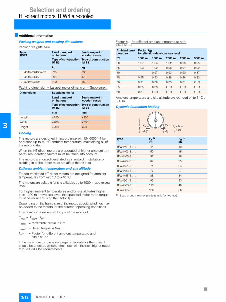
Selection and orderingHT-direct motors 1FW4 air-cooled
3/12 Siemens D 86.2 · 2007
3
■ Additional information
Packing weights and packing dimensions
Packing weights, tare
Packing dimension = Largest motor dimension + Supplement
Cooling
The motors are designed in accordance with EN 60034-1 for operation up to 40 °C ambient temperature, maintaining all of the motor data.
When the HT-direct motors are operated at higher ambient tem-peratures, derating factors must be taken into account.
The motors are forced-ventilated as standard. Installation or building in of the motor must not affect the air inlet.
Different ambient temperature and site altitude
Forced-ventilated HT-direct motors are designed for ambient temperatures from –20 °C to +40 °C.
The motors are suitable for site altitudes up to 1000 m above sea level.
For higher ambient temperatures and/or site altitudes higher than 1000 m above sea level, the specified motor rated torque must be reduced using the factor kHT.
Depending on the frame size of the motor, special windings may be added to the motors for the different operating conditions.
This results in a maximum torque of the motor of:
Tmax = Trated · kHT
Tmax = Maximum torque in Nm
Trated = Rated torque in Nm
kHT = Factor for different ambient temperature and site altitude
If the maximum torque is no longer adequate for the drive, it should be checked whether the motor with the next higher rated torque fulfills the requirements.
Factor kHT for different ambient temperature and site altitude
Ambient temperature and site altitude are rounded off to 5 °C or 500 m.
Dynamic foundation loading
1) Load at one motor long side (that is for two feet).
Type 1FW4 . . .
Land transport on battensType of construction IM B3
Sea transport in wooden casesType of construction IM B3
kg kg
. . . 401/403/405/407 90 395
. . . 451/453/455 95 470
. . . 501/503/505 100 550
Dimensions Supplements for
Land transport on battensType of construction IM B3
Sea transport in wooden casesType of construction IM B3
mm mm
Length +250 +250
Width +200 +200
Height +200 +500
Ambient tem-perature
Factor kHT for site altitude above sea level
°C 1000 m 1500 m 2000 m 2500 m 3000 m
30 1.07 1.04 1.02 0.98 0.95
35 1.03 1.02 0.98 0.94 0.92
40 1 0.97 0.93 0.90 0.87
45 0.95 0.93 0.88 0.86 0.83
50 0.91 0.88 0.83 0.81 O. R.
55 0.85 0.83 O. R. O. R. O. R.
60 0.8 O. R. O. R. O. R. O. R.
Type FA 1)
kNFB
1)
kN
1FW4401-3 . . . 44 10
1FW4403-3 . . . 50 15
1FW4405-3 . . . 57 18
1FW4407-3 . . . 67 25
1FW4451-3 . . . 71 24
1FW4453-3 . . . 77 27
1FW4455-3 . . . 88 34
1FW4501-3 . . . 93 33
1FW4503-3 . . . 113 48
1FW4505-3 . . . 136 66
(F )A
FB(F )B
FA
G_
D0
86
_E
N_
00
02
6
F = DownA
F = UpB

Siemens D 86.2 · 2007
4/2 Configuration
Configuring

Configuring
4/2 Siemens D 86.2 · 2007
4
■ Configuration
HT-direct motors can only be operated in combination with SINAMICS converters. The drive system can be completely con-figured using the “SINAMICS MICROMASTER SIZER” configura-tion tool.
These motors cannot be used as line-fed machines (no self-starting capability).
Guideline for drive selection
These “guideline for drive selection” guide you step-by-step to the required HT-direct motor and SINAMICS converter:
Step 1 Technical requirements for the motor (example) Further notes and alternatives
Determine the required product profileRequired is, for example:
Torque in continuous operation (Tcont.)
16000 Nm T = Pmech [kW] x 9550 / n [rpm] = 1282 x 9550 / 765T = 16000 Nm
Short-term overload torque (Toverload)
18000 Nm Toverload/Tcont. < 1.5: Rated torque = Tcont.
Toverload/Tcont. > 1.5: Rated torque = Toverload/1.5Higher overloads on request.
Duty type S1 When, instead of S1 duty, duty cycles must be taken into account:Average torque is calculated from the root of the square of the required torques multiplied by the time divided by the total time: e.g. 140%, 10 seconds, then 80%, 30 seconds, results in an average 98.5% of the rated torque:
Utilization Temperature class 155 (previously temperature class F)
In case of use according to temperature class 130 (previously temperature class B), the motor must be designed for a torque 20% higher:e.g. Tcont. = 1.2 x 16000 = 19200 Nm
Rated voltage 690 V Alternatively 400 V or 460 V
Max. speed in continuous operation
765 rpm Rated speed acc. to catalog 800 rpm, max. perm. speed 20% higher (800 x 1.2 = 960 rpm)For speeds below 170 rpm the option L1Y must be selected (anormal stator winding).
Cooling medium Water with max. inlet temperature 25 °C
Higher cooling-water inlet temperatures must be accounted for with derating factors when the rated torque is determined:e.g. for 35 °C: 16000/0.95 = 16840 Nm For derating factors, see Page 2/10.
Type of construction IM B3
Step 2 Environmental requirements for the motor Further notes and alternatives
Determine the installation conditions
Ambient temperature –20 to +40 °C At ambient temperatures up to +40 °C, derating factors are not required for water-cooled motors. At higher ambient temperatures in combination with cooling-water inlet temperatures above 25 °C, the derating factors on Page 2/10 are applicable. For air-cooled motors, derating factors must be used in accordance to Page 3/12.
Site altitude < 1000 m For water-cooled motors, the site altitude does not have to be taken into account for the derating factor. For site altitudes > 1000 m above sea level, the conditions of the converter must however be taken into account.For air-cooled motors, derating factors must be used in accordance to Page 3/12.
Step 3 Selecting the motor Further notes and alternatives
Determining the motor Order No.
1FW4453-1HF70-1AA0 See “Selection and ordering data” (Section 2). Due to the current-carrying capability of the motor terminal box (max. 1230 A), the motor is designed with two terminal boxes and two galvanically iso-lated winding systems.
1 40, 2 10 0 802, 30×+×( ) 40⁄ 0 985,=
➠➠
➠
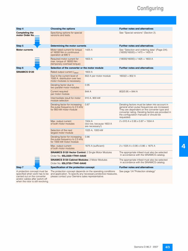
Configuring
4/3Siemens D 86.2 · 2007
4
Step 4 Choosing the options Further notes and alternatives
Completing themotor Order No.
Specifying options for special versions and tests.
See “Special versions” (Section 2).
Step 5 Determining the motor currents Further notes and alternatives
Motor currents Motor rated current for torque of 16000 Nm in continuous operation at 690 V
1425 A See “Selection and ordering data” (Page 2/4).(16000/16500) x 1470 = 1425 A
Required motor current for max. torque of 18000 Nm (temporary overload torque)
1603 A (18000/16000) x 1425 = 1603 A
Step 6 Selection of the converter or the motor module Further notes and alternatives
SINAMICS S120 Rated output current Irated 1603 A
Due to the current level of 1593 A, distribution over two motor modules is necessary.
802 A per motor module 1603/2 = 802 A
Derating factor due to two parallel motor modules
0.95
Current required per motor module
844 A 802/0.95 = 844 A
Intermediate result for motor module selection
910 A, 900 kW
Derating factor for increasing the pulse frequency to 2.5 kHzfor 900 kW motor module
0.87 Derating factors must be taken into account in general when pulse frequencies are increased. They are dependent on the converter type and converter rating. Derating factors are provided in the configuration manuals or should be requested.
Max. output current of both motor modules
1504 A(too low, because 1603 A are necessary!)
2 x 910 A x 0.95 x 0.87 = 1504 A
Selection of the next largest motor module
1025 A, 1000 kW
Derating factor for increasing the pulse frequency to 2.5 kHzfor 1000 kW motor module
0.86
Max. output current of both motor modules
1675 A (sufficient) 2 x 1025 A x 0.95 x 0.86 = 1675 A
SINAMICS S120 Vector Control: 2 Single Motor ModulesOrder No. 6SL3320-1TH41-0AA0
The appropriate infeed must also be selected in accordance with the SINAMICS catalog.
SINAMICS S120 Cabinet Modules: 2 Motor ModulesOrder No. 6SL3720-1TH41-0AA0
The appropriate infeed must also be selected in accordance with the SINAMICS catalog.
Step 7 Specification of the protection concept Further notes and alternatives
A protection concept must be specified when work has to be carried out on the converter and/or cables after switch-off when the rotor is still revolving.
The protection concept depends on the operating conditions and application. To specify any necessary protective measures, please contact your Siemens sales representative.
See page 1/4 "Protection strategy"
➠➠
➠

Configuring
Notes
4/4 Siemens D 86.2 · 2007
4

Siemens D 86.2 · 2007
55/2 Siemens contact partners worldwide5/3 A&D online services5/4 Customer support5/6 Conditions of sale and delivery5/6 Export regulations
Appendix
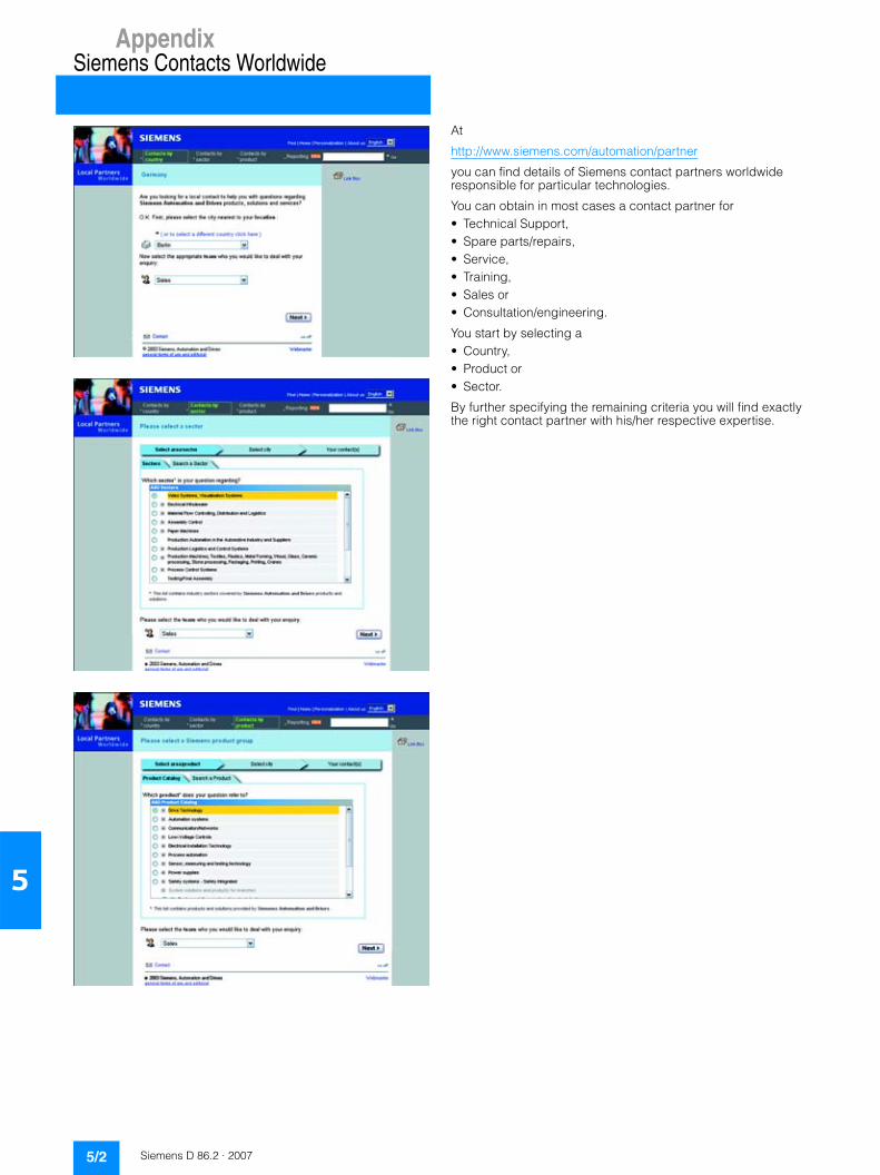
AppendixSiemens Contacts Worldwide
5/2 Siemens D 86.2 · 2007
5
At
http://www.siemens.com/automation/partner
you can find details of Siemens contact partners worldwide responsible for particular technologies.
You can obtain in most cases a contact partner for• Technical Support,• Spare parts/repairs,• Service,• Training,• Sales or• Consultation/engineering.
You start by selecting a• Country,• Product or• Sector.
By further specifying the remaining criteria you will find exactly the right contact partner with his/her respective expertise.

AppendixA&D Online ServicesInformation and Ordering
in the Internet and on CD-ROM
5/3Siemens D 86.2 · 2007
5
■ A&D in the WWWA detailed knowledge of the range of products and services available is essential when planning and configuring automation systems. It goes without saying that this information must always be fully up-to-date.
The Siemens Automation and Drives Group (A&D) has therefore built up a comprehensive range of information in the World Wide Web, which offers quick and easy access to all data required.
Under the address
http://www.siemens.com/automation
you will find everything you need to know about products, sys-tems and services.
■ Product Selection Using the Offline Mall of Automation and DrivesDetailed information together with convenient interactive functions: The Offline Mall CA 01 covers more than 80,000 products and thus provides a full summary of the Siemens Automation and Drives product base.
Here you will find everything that you need to solve tasks in the fields of automation, switchgear, installation and drives. All information is linked into a user interface which is easy to work with and intuitive.
After selecting the product of your choice you can order at the press of a button, by fax or by online link.
Information on the Offline Mall CA 01 can be found in the Internet under
http://www.siemens.com/automation/ca01
or on CD-ROM or DVD.
■ Easy Shopping with the A&D Mall The A&D Mall is the virtual department store of Siemens AG in the Internet. Here you have access to a huge range of products presented in electronic catalogs in an informative and attractive way.
Data transfer via EDIFACT allows the whole procedure from selection through ordering to tracking of the order to be carried out online via the Internet.
Numerous functions are available to support you.
For example, powerful search functions make it easy to find the required products, which can be immediately checked for avail-ability. Customer-specific discounts and preparation of quotes can be carried out online as well as order tracking and tracing.
Please visit the A&D Mall on the Internet under:
http://www.siemens.com/automation/mall

AppendixCustomer Support
Our Services for Every Phase of Your Project
5/4 Siemens D 86.2 · 2007
5
.I
In the face of harsh competition you need optimum conditions to keep ahead all the time: A strong starting position. A sophisticated strategy and team for the necessary support - in every phase. Service & Support from Siemens provides this support with a complete range of different services for automation and drives.
In every phase: from planning and startup to maintenance and upgrading.
Our specialists know when and where to act to keep the produc-tivity and cost-effectiveness of your system running in top form.
■ Online SupportThe comprehensive information system available round the clock via Internet ranging from Product Support and Service & Support services to Support Tools in the Shop.
http://www.siemens.com/automation/service&support
■ Technical SupportCompetent consulting in techni-cal questions covering a wide range of customer-oriented ser-vices for all our products and systems.
Tel.: +49 (0)180 50 50 222Fax: +49 (0)180 50 50 223http://www.siemens.com/automation/support-request
■ Technical ConsultingSupport in the planning and designing of your project from detailed actual-state analysis, target definition and consulting on product and system ques-tions right to the creation of the automation solution. 1)
■ Configuration and Software EngineeringSupport in configuring and de-veloping with customer-oriented services from actual configura-tion to implementation of the automation project. 1)
■ Service On SiteWith Service On Site we offer services for startup and mainte-nance, essential for ensuring system availability.
In Germany 0180 50 50 444 1)
■ Repairs and Spare PartsIn the operating phase of a ma-chine or automation system we provide a comprehensive repair and spare parts service ensur-ing the highest degree of oper-ating safety and reliability.
In Germany 0180 50 50 446 1)
■ Optimization and UpgradingTo enhance productivity and save costs in your project we offer high-quality services in optimization and upgrading. 1)
1) For country-specific telephone numbers go to our Internet site at: http://www.siemens.com/automation/service&support

AppendixCustomer Support
5/5Siemens D 86.2 · 2007
5
■ Knowledge Base on CD-ROM
For locations without online connections to the Internet there are excerpts of the free part of the information sources avail-able on CD-ROM (Service & Support Knowledge Base). This CD-ROM contains all the latest product information at the time of production (FAQs, Down-loads, Tips and Tricks, Updates) as well as general information on Service and Technical Sup-port.
The CD-ROM also includes a full-text search and our Knowledge Manager for targeted searches for solutions. The CD-ROM will be updated every 4 months.
Just the same as our online offer in the Internet, the Service & Support Knowledge Base on CD comes complete in 5 lan-guages (German, English, French, Italian, Spanish).
You can order the Service & Support Knowledge Base CD from your Siemens contact.
Order no. 6ZB5310-0EP30-0BA2
Orders via the Internet (with Automation Value Card or credit card) at:
http://www.siemens.com/automation/service&support
in the Shop domain.
■ Automation Value Card
Small card - great support
The Automation Value Card is an integral component of the com-prehensive service concept with which Siemens Automation and Drives will accompany you in each phase of your automation project.
It doesn't matter whether you want just specific services from our Technical Support or want to purchase high-quality Support Tools in our Online Shop, you can always pay with your Automa-tion Value Card. No invoicing, transparent and safe. With your personal card number and associated PIN you can view the state of your account and all transactions at any time.
Services on card. This is how it's done.
Card number and PIN are on the back of the Automation Value Card. When delivered, the PIN is covered by a scratch field, guaranteeing that the full credit is on the card.
By entering the card number and PIN you have full access to the Service & Support services being offered. The charge for the services procured is debited from the credits on your Automa-tion Value Card.
All the services offered are marked in currency-neutral credits, so you can use the Automation Value Card worldwide.
Detailed information on the services offered is available on our Internet site at:
http://www.siemens.com/automation/service&support
Service & Support à la Card: Examples
■ Additional information
• H-compact on the Internet: www.siemens.com/h-compact
• N-compact Catalog D81.1 Order No. E86060-K5581-A111-A1 on the Internet: www.siemens.com/n-compactOnline Catalog CA01 www.siemens.com/automation/ca01
• SINAMICS G150Catalog D11 Order No. E86060-K5511-A101-A2 on the Internet: www.siemens.com/sinamics-g150
Automation Value Card order numbers
Credits Order no.
200 6ES7 997-0BA00-0XA0
500 6ES7 997-0BB00-0XA0
1000 6ES7 997-0BC00-0XA0
10000 6ES7 997-0BG00-0XA0
Technical Support
“Priority” Priority processing for urgent cases
“24 h” Availability round the clock
“Extended” Technical consulting for complex questions
Support Tools in the Support Shop
“System Utili-ties”
Tools that can be used directly for configuration, anal-ysis and testing
“Applications” Complete topic solutions including ready-tested soft-ware
“Functions & Samples”
Adaptable blocks for accelerating your developments

Appendix
Conditions of sale and delivery
5/6 Siemens D 86.2 · 2007
5
■ Terms and Conditions of Sale and Delivery
By using this catalog you can acquire hardware and software products described therein from Siemens AG subject to the following terms. Please note! The scope, the quality and the con-ditions for supplies and services, including software products, by any Siemens entity having a registered office outside of Ger-many, shall be subject exclusively to the General Terms and Conditions of the respective Siemens entity. The following terms apply exclusively for orders placed with Siemens AG.
For customers with a seat or registered office in GermanyThe “General Terms of Payment” as well as the “General Condi-tions for the Supply of Products and Services of the Electrical and Electronics Industry” shall apply.For software products, the “General License Conditions for Soft-ware Products for Automation and Drives for Customers with a Seat or registered Office in Germany” shall apply.
For customers with a seat or registered office outside of GermanyThe “General Terms of Payment” as well as the “General Condi-tions for Supplies of Siemens, Automation and Drives for Cus-tomers with a Seat or registered Office outside of Germany” shall apply.For software products, the “General License Conditions for Soft-ware Products for Automation and Drives for Customers with a Seat or registered Office outside of Germany” shall apply.
GeneralThe dimensions are in mm. In Germany, according to the Ger-man law on units in measuring technology, data in inches only apply to devices for export. Illustrations are not binding.Insofar as there are no remarks on the corresponding pages, - especially with regard to data, dimensions and weights given - these are subject to change without prior notice.The prices are in € (Euro) ex works, exclusive packaging.The sales tax (value added tax) is not included in the prices. It shall be debited separately at the respective rate according to the applicable legal regulations.Prices are subject to change without prior notice. We will debit the prices valid at the time of delivery.Surcharges will be added to the prices of products that contain silver, copper, aluminum, lead and/or gold if the respective basic official prices for these metals are exceeded. These surcharges will be determined based on the official price and the metal fac-tor of the respective product.The surcharge will be calculated on the basis of the official price on the day prior to receipt of the order or prior to the release order.The metal factor determines the official price as of which the metal surcharges are charged and the calculation method used. The metal factor, provided it is relevant, is included with the price information of the respective products.
An exact explanation of the metal factor and the text of the Comprehensive Terms and Conditions of Sale and Delivery are available free of charge from your local Siemens business office under the following Order Nos.:• 6ZB5310-0KR30-0BA1
(for customers based in Germany)• 6ZB5310-0KS53-0BA1
(for customers based outside Germany)or download them from the Internethttp://www.siemens.com/automation/mall (Germany: A&D Mall Online-Help System)
■ Export regulations
The products listed in this catalog/price list may be subject to European/German and/or US export regulations.Therefore, any export requiring a license is subject to approval by the competent authorities.According to current provisions, the following export regulations must be observed with respect to the products featured in this catalog/price list:
Even without a label or with an “AL: N” or “ECCN: N”, authoriza-tion may be required due to the final destination and purpose for which the goods are to be used. The deciding factors are the AL or ECCN export authorization indicated on order confirmations, delivery notes and invoices.Errors excepted and subject to change without prior notice.
A&D/VuL_ohne MZ/En 05.09.06
AL Number of the German Export ListProducts marked other than “N” require an export license. In the case of software products, the export des-ignations of the relevant data medium must also be generally adhered to.Goods labeled with an “AL” not equal to “N” are subject to a European or German export authori-zation when being exported out of the EU.
ECCN Export Control Classification NumberProducts marked other than “N” are subject to a reexport license to specific countries.In the case of software products, the exportdesignations of the relevant data medium must also be generally adhered to.Goods labeled with an “ECCN” not equal to “N” are subject to a US re-export authorization.
Catalogs of theAutomation and Drives Group (A&D)
Further information can be obtained from our branch offices listedin the appendix or at www.siemens.com/automation/partner
A&D/3U/En 13.12.06
Automation and Drives CatalogInteractive catalog on CD-ROM and on DVD
• The Offline Mall of Automation and Drives CA 01
Automation Systems for Machine ToolsSINUMERIK & SIMODRIVE NC 60
SINUMERIK & SINAMICS NC 61
Drive SystemsVariable-Speed Drives
SINAMICS G130 Drive Converter Chassis Units, SINAMICS G150 Drive Converter Cabinet Units
D 11
SINAMICS G110 Inverter Chassis Units D 11.1
SINAMICS GM150/SINAMICS SM150 Medium-Voltage Converters
D 12
SINAMICS S120 Drive Converter Systems D 21.1
SINAMICS S150 Drive Converter Cabinet Units D 21.3
Asynchronous Motors Standardline D 86.1
Synchronous Motors with Permanent-Magnet Technology, HT-direct
D 86.2
DC Motors DA 12
SIMOREG DC MASTER 6RA70 Digital Chassis Converters
DA 21.1
SIMOREG K 6RA22 Analog Chassis Converters DA 21.2
SIMOREG DC MASTER 6RM70 Digital Converter Cabinet Units
DA 22
SIMOVERT PM Modular Converter Systems DA 45
SIEMOSYN Motors DA 48
MICROMASTER 410/420/430/440 Inverters DA 51.2
MICROMASTER 411/COMBIMASTER 411 DA 51.3
SIMOVERT MASTERDRIVES Vector Control DA 65.10
SIMOVERT MASTERDRIVES Motion Control DA 65.11
Synchronous and asynchronous servomotors for SIMOVERT MASTERDRIVES
DA 65.3
SIMODRIVE 611 universal and POSMO DA 65.4
Low-Voltage Three-Phase-Motors
IEC Squirrel-Cage Motors D 81.1
Automation Systems for Machine Tools SIMODRIVE NC 60
• Main Spindle/Feed Motors
• Converter Systems SIMODRIVE 611/POSMO
Automation Systems for Machine Tools SINAMICS NC 61
• Main Spindle/Feed Motors
• Drive System SINAMICS S120
Drive and Control Components for Hoisting Equipment HE 1
Electrical Installation TechnologyPDF: ALPHA Small Distribution Boards and
Distribution Boards, Terminal BlocksET A1
PDF: ALPHA 8HP Molded-Plastic Distribution System ET A3
PDF: BETA Low-Voltage Circuit Protection ET B1
PDF: DELTA Switches and Socket Outlets ET D1
GAMMA Building Controls ET G1
Human Machine Interface Systems SIMATIC HMI ST 80
PDF: These catalogs are only available as pdf files.
Industrial Communication for Automation and Drives
CatalogIK PI
Low-VoltageControls and Distribution – SIRIUS, SENTRON, SIVACON
LV 1
Controls and Distribution – Technical InformationSIRIUS, SENTRON, SIVACON
LV 1 T
SIDAC Reactors and Filters LV 60
SIVENT Fans LV 65
SIVACON 8PS Busbar Trunking Systems LV 70
Motion Control System SIMOTION PM 10
Process Instrumentation and AnalyticsField Instruments for Process AutomationMeasuring Instruments for Pressure, Differential Pressure, Flow, Level and Temperature, Positioners and Liquid Meters
FI 01
PDF: Indicators for panel mounting MP 12
SIREC Recorders and Accessories MP 20
SIPART, Controllers and Software MP 31
SIWAREX Weighing Systems WT 01
Continuous Weighing and Process Protection WT 02
Process Analytical Instruments PA 01
PDF: Process Analytics, Components for the System Integration
PA 11
SIMATIC Industrial Automation SystemsSIMATIC PCS Process Control System ST 45
Products for Totally Integrated Automation and Micro Automation
ST 70
SIMATIC PCS 7 Process Control System ST PCS 7
Add-ons for the SIMATIC PCS 7 Process Control System
ST PCS 7.1
Migration solutions with the SIMATIC PCS 7 Process Control System
ST PCS 7.2
pc-based Automation ST PC
SIMATIC Control Systems ST DA
SIMATIC Sensors FS 10
SIPOS Electric ActuatorsElectric Rotary, Linear and Part-turn Actuators MP 35
Electric Rotary Actuators for Nuclear Plants MP 35.1/.2
Systems EngineeringPower supplies SITOP power KT 10.1
System cabling SIMATIC TOP connect KT 10.2
System SolutionsApplications and Products for Industry are part of the interactive catalog CA 01
TELEPERM M Process Control SystemPDF: AS 488/TM automation systems PLT 112
���������������� �
� �� �����������������������������
����������
������������ ������ ��� ����������������������� �!" ##" $��%
&&&'������'���(���������
��������� ������������� ������ ������ ����������� ��������� ��� ��������������������������������� ����������� ���������������������������������������������������� ����� ������������ �� ������� ����������� ��� ������� �������� ��������� ��� ����������������� ���������������������� ��� �������� �� ������������ ����� ������������������ ������������� � ���������� �� �� ����
�������� �������� ����������� ������������� ������������������������������������������������� ������ ������ ���������������������� �� ������ ���� ��������
)�*+��������
��&���
���,
�� �����-���,�
./�
��-0#���
��'�"�/
"(�
��.�
�-� �����#� ��
1-2)����
��#���
�