Motor Protection Circuit Breaker J7MN€¦ · Motor Protection Circuit Breaker J7MN 1 Motor...
14
Motor Protection Circuit Breaker J7MN 1 Motor Protection Circuit Breaker J7MN MPCB system • Rotary and switch types • Rated operational current 32 A, 63 A and 100 A • Switching capacity up to 100 kA/400 V • Fixed short-circuit release = 13 x I u • Overload release adjustable 0.65 - 1 x I u • Motor protection CLASS 10 • Fulfill all needed standards Options • ON/OFF indication • Trip alarm/indication • Undervoltage release • Shunt release • Three phase busbar system • Moulded plastic enclosures • Door coupling rotary mechanisms • Insulated Link modules ) Ordering Information ■ Model Number Legend 1. Motor Protection Circuit Breaker 2. Options for MPCB 3. Busbars, line side terminals and shrouds J7MN-##-### 1 2 3 1) Motor Protection Circuit Breaker 2) Type/range 3) Setting range J77MN-##-### 1 2 3 1) Options MPCB 2) Auxiliary contacts T: Trip indicator U: Undervoltage release S: Shuntrelease DC: Door-coupling HU: DIN-rail adaptors V: Link modules PF: Enclosure 3) Other specifications J75-###-### 1 2 3 1) Options MPCB 2) CPM: Busbars BTC: Line side TA: Shrouds 3) Other specifications AUDIN - 8, avenue de la malle - 51370 Saint Brice Courcelles - Tel : 03.26.04.20.21 - Fax : 03.26.04.28.20 - Web : http: www.audin.fr - Email : [email protected]
Transcript of Motor Protection Circuit Breaker J7MN€¦ · Motor Protection Circuit Breaker J7MN 1 Motor...
Motor Protection Circuit Breaker J7MN 1
Motor Protection Circuit Breaker
J7MNMPCB system
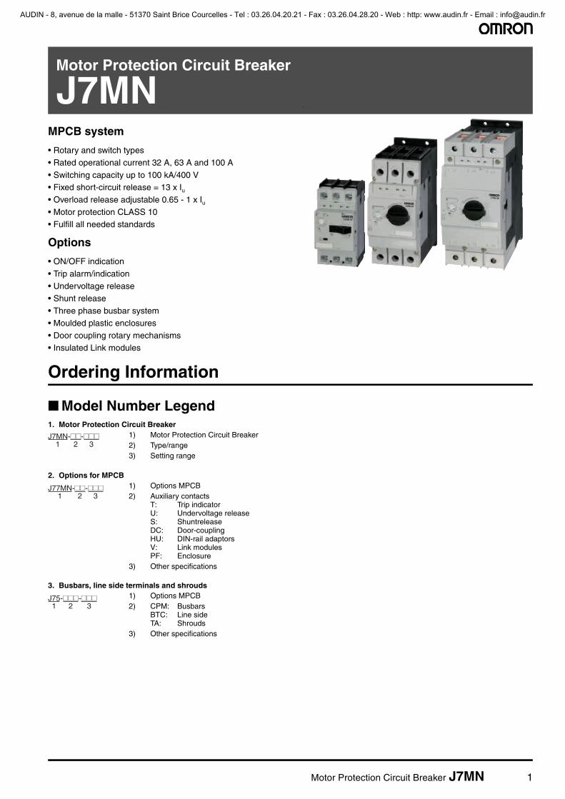
• Rotary and switch types
• Rated operational current 32 A, 63 A and 100 A
• Switching capacity up to 100 kA/400 V• Fixed short-circuit release = 13 x Iu• Overload release adjustable 0.65 - 1 x Iu• Motor protection CLASS 10• Fulfill all needed standards
Options
• ON/OFF indication
• Trip alarm/indication
• Undervoltage release• Shunt release
• Three phase busbar system
• Moulded plastic enclosures• Door coupling rotary mechanisms
• Insulated Link modules
)
Ordering Information
■ Model Number Legend1. Motor Protection Circuit Breaker
2. Options for MPCB
3. Busbars, line side terminals and shrouds
J7MN-##-###1 2 3
1) Motor Protection Circuit Breaker2) Type/range3) Setting range
J77MN-##-###1 2 3
1) Options MPCB2) Auxiliary contacts
T: Trip indicatorU: Undervoltage releaseS: ShuntreleaseDC: Door-couplingHU: DIN-rail adaptorsV: Link modulesPF: Enclosure
3) Other specifications
J75-###-###1 2 3
1) Options MPCB2) CPM: Busbars
BTC: Line sideTA: Shrouds
3) Other specifications
AUDIN - 8, avenue de la malle - 51370 Saint Brice Courcelles - Tel : 03.26.04.20.21 - Fax : 03.26.04.28.20 - Web : http: www.audin.fr - Email : [email protected]

2 Motor Protection Circuit Breaker J7MN
■ System overview
Motor Protection Circuit Breaker
Rated Current In Suitable for motors 3~400 V
Setting range Thermal Overload Release
Instantaneous Short Circuit Release
Short Circuit Breaking Capacity at 3~400 V
Type
A kW A A kA (Icu)
0.16 - 0.10 - 0.16 2.1 100 J7MN-3P-E16
0.25 0.06 0.16 - 0.25 3.3 100 J7MN-3P-E25
0.4 0.09 0.25 - 0.4 5.2 100 J7MN-3P-E4
0.63 0.18 0.4 - 0.63 8.2 100 J7MN-3P-E63
1 0.25 0.63 - 1 13 100 J7MN-3P-1
1.6 0.55 1 - 1.6 20.8 100 J7MN-3P-1E6
2.5 0.75 1.6 - 2.5 32.5 100 J7MN-3P-2E5
4 1.5 2.5 - 4 52 100 J7MN-3P-4
6 2.2 4 - 6 78 100 J7MN-3P-6
8 3 5 - 8 104 100 J7MN-3P-8
10 4 6 - 10 130 50 J7MN-3P-10
13 5.5 9 - 13 169 50 J7MN-3P-13
17 7.5 11 - 17 221 20 J7MN-3P-17
22 7.5 14 - 22 286 15 J7MN-3P-22
26 11 18 - 26 338 15 J7MN-3P-26
32 15 22 - 32 416 15 J7MN-3P-32
0.16 - 0.10 - 0.16 2.1 100 J7MN-3R-E16
0.25 0.06 0.16 - 0.25 3.3 100 J7MN-3R-E25
0.4 0.09 0.25 - 0.4 5.2 100 J7MN-3R-E4
0.63 0.18 0.4 - 0.63 8.2 100 J7MN-3R-E63
1 0.25 0.63 - 1 13 100 J7MN-3R-1
1.6 0.55 1 - 1.6 20.8 100 J7MN-3R-1E6
2.5 0.75 1.6 - 2.5 32.5 100 J7MN-3R-2E5
4 1.5 2.5 - 4 52 100 J7MN-3R-4
6 2.2 4 - 6 78 100 J7MN-3R-6
8 3 5 - 8 104 100 J7MN-3R-8
10 4 6 - 10 130 100 J7MN-3R-10
13 5.5 9 - 13 169 100 J7MN-3R-13
17 7.5 11 - 17 221 50 J7MN-3R-17
22 7.5 14 - 22 286 50 J7MN-3R-22
26 11 18 - 26 338 50 J7MN-3R-26
32 15 22 - 32 416 50 J7MN-3R-32
26 12.5 18 - 26 338 50 J7MN-6R-26
32 15 22 - 32 416 50 J7MN-6R-32
40 18.5 28 - 40 520 50 J7MN-6R-40
50 22 34 - 50 650 50 J7MN-6R-50
63 30 45 - 63 819 50 J7MN-6R-63
63 30 45 - 63 819 50 J7MN-9R-63
75 37 55 - 75 975 50 J7MN-9R-75
90 45 70 - 90 1170 50 J7MN-9R-90
100 - 80 - 100 1300 50 J7MN-9R-100
J7MN-3P
J7MN-3R
J7MN-6R
J7MN-9R
AUDIN - 8, avenue de la malle - 51370 Saint Brice Courcelles - Tel : 03.26.04.20.21 - Fax : 03.26.04.28.20 - Web : http: www.audin.fr - Email : [email protected]

Motor Protection Circuit Breaker J7MN 3
Accessories
Description Mounting place
Max. per MPCB
Contacts Rated Operating Current
Type
AC15 AC1
24 V 240 V 240 V
NO NC A A A
Transverse Auxiliary Contact block Front 1 1 1 3 2 5 J77MN-11F
2 - 3 2 5 J77MN-20F
- 2 3 2 5 J77MN-02F
Side Auxiliary Contact block Left hand side
1 1 1 6 4 10 J77MN-11S
2 - 6 4 10 J77MN-20S
- 2 6 4 10 J77MN-02S
Any Trip Alarm Signalling switch suitable for J7MN-3
Left hand side
1 1 1 6 4 10 J77MN-TA-11S
Signalling switch suitable for J7MN-6 & J7MN-9
Left hand side
1 1 1 6 4 10 J77MN-TB-11S
Short circuit Trip Alarm Signalling switch Left hand side
1 1 1 6 4 10 J77MN-T-11S
Description Mounting place
Max. per MPCB
Rated voltages Type
Undervoltage Release Trips the circuit-breaker when the voltage is interrupted. Pre-vents the motor from being re-started accidentally when the voltage is restored, suitable for EMERGENCY STOP acc. to VDE 0113
Right hand side
1 24 V 50 Hz, 28 V 60 Hz J77MN-U-24
110 - 127 V 50 Hz, 120 V 60 Hz J77MN-U-110
220 - 230 V 50 Hz, 240 - 260 V 60 Hz J77MN-U-230
240 V 50 Hz, 277 V 60 Hz J77MN-U-240
380 - 400 V 50 Hz, 440 - 460 V 60 Hz J77MN-U-400
415 - 440 V 50 Hz, 460 - 480 V 60 Hz J77MN-U-415
Shunt Release Trips the circuit-breaker when the release coil energized.
Right hand side
1 24 V 50 Hz, 28 V 60 Hz J77MN-S-24
110 - 127 V 50 Hz, 120 V 60 Hz J77MN-S-110
220 - 230 V 50 Hz, 240 - 260 V 60 Hz J77MN-S-230
240 V 50 Hz, 277 V 60 Hz J77MN-S-240
380 - 400 V 50 Hz, 440 - 460 V 60 Hz J77MN-S-400
415 - 440 V 50 Hz, 460 - 480 V 60 Hz J77MN-S-415
Description Type
Enclosure Plastic enclose with rotary operating mechanism, lockable space for aux. contact + release, IP65 J77MN-PF-3R
Enclose with rotary operating mechanism yellow - red, lock space for aux. contact + release, IP65 J77MN-PFC-3R
AUDIN - 8, avenue de la malle - 51370 Saint Brice Courcelles - Tel : 03.26.04.20.21 - Fax : 03.26.04.28.20 - Web : http: www.audin.fr - Email : [email protected]

4 Motor Protection Circuit Breaker J7MN
Description Applicable MPCBs
Shaft length Type
Door-coupling rotary mechanism IP65; black/grey
The door locking device prevents accidental opening of the cubicle door in the ON position of the circuit-breaker. The OFF position can be locked with up to 3 padlocks
J7MN-3R 115 mm J77MN-DC-3R-115-B
315 mm J77MN-DC-3R-315-B
J7MN-6R 115 mm J77MN-DC-6R-115-B
315 mm J77MN-DC-6R-315-B
J7MN-9R 115 mm J77MN-DC-9R-115-B
315 mm J77MN-DC-9R-315-B
Door-coupling rotary mechanism IP65; red/yellow
J7MN-3R 115 mm J77MN-DC-3R-115-RY
315 mm J77MN-DC-3R-315-RY
J7MN-6R 115 mm J77MN-DC-6R-115-RY
315 mm J77MN-DC-6R-315-RY
J7MN-9R 115 mm J77MN-DC-9R-115-RY
315 mm J77MN-DC-9R-315-RY
Description Type
Link modules Mechanical and electrical connection between Motor Protection Circuit Breaker and Contactor. Up-to max. 32 A.
Mini Motor Contactor J7KNA J77MN-VKA-3
Motor Contactor J7KN J77MN-VKN-3
Motor Contactor J7KNG J77MN-VKG-3
Electrical connection between Motor Protection Circuit Breaker and Contactor.
Up-to 32 A J77MN-VD-3
Up-to 63 A J77MN-VD-6
J77MN-VDG-6
Up-to 100 A J77MN-VD-9
DIN-rail adaptors For mechanical fixing of circuit-breaker and contactor. With two moveable DIN-rail clips for easy mounting & replacing. Can be connected to one 35W x 15H mm DIN-rail or two 35W x 7.5H mm DIN-rails.
For J7MN-3 and J7KN(G)-10 up-to J7KN(G)-40
J77MN-HU-3
For mechanical fixing of circuit-breaker and contactor. Can be connected to one 35W x 15H mm DIN-rail or two 35W x 7.5H mm DIN-rails.
For J7MN-6 and J7KN(G)-24 up-to J7KNG-40 and/or J7KN-62
J77MN-HU-6
For J7MN-9 and J7KN-50 up-to J7KN-74
J77MN-HU-9
Scale cover sealable for covering the current setting scale (1 bag with 10 units) J77MN-K
Push-in lugs for screwing the circuit-breaker onto mounting plates. 2 units required (1 bag with 20 units)
J77MN-L
Insulation barriers Up to 600 V acc.UL 489 for increased distances and clearances acc. to UL Type "E“ 4 pcs per device (2 pcs on each side) (pack 2 units)
J77MN-TB100
AUDIN - 8, avenue de la malle - 51370 Saint Brice Courcelles - Tel : 03.26.04.20.21 - Fax : 03.26.04.28.20 - Web : http: www.audin.fr - Email : [email protected]

Motor Protection Circuit Breaker J7MN 5
Insulated 3-Phase Busbar System IP20
Description Connection type
Version For Units (MPCB)
Pack pcs
Type
3-phase busbars; modular spacing = 45 mm
Spade for 2 units J7MN-3P; J7MN-3R
1 J77MN-CPM-3-45-2S
for 3 units 1 J77MN-CPM-3-45-3S
for 4 units 1 J77MN-CPM-3-45-4S
for 5 units 1 J77MN-CPM-3-45-5S
Line side terminal 3-pole, connection from above; conductor cross-section solid or stranded 6-25 mm² with end sleeve 4-16 mm²
Spade acc. IEC/EN 60947-1, 60947-2, 60947-4-1 and VDE 0660
J7MN-3P; J7MN-3R
1 J77MN-BTC-63-SE
Line side terminal 3-pole, connection from above; conductor cross-section solid or stranded 6-25 mm² with end sleeve 4-16 mm²
Spade up to 600V acc. UL 489 J7MN-3P; J7MN-3R
1 J77MN-BTC-63-SEV
Shrouds for unused terminals on busbar system
Spade J7MN-3P; J7MN-3R
1 J77MN-TA-63S
3-phase busbars; modular spacing = 45 mm
Pin for 2 units J7MN-3P; J7MN-3R
1 J77MN-CPM-3-45-2
for 3 units 1 J77MN-CPM-3-45-3
for 4 units 1 J77MN-CPM-3-45-4
for 5 units 1 J77MN-CPM-3-45-5
3-phase busbars; modular spacing = 54 mm
Pin for 2 units J7MN-3P; J7MN-3R
1 J77MN-CPM-3-54-2
for 3 units 1 J77MN-CPM-3-54-3
for 4 units 1 J77MN-CPM-3-54-4
for 5 units 1 J77MN-CPM-3-54-5
Line side terminal 3-pole, connection from above; conductor cross-section solid or stranded 6-25 mm² with end sleeve 4-16 mm²
Pin acc. IEC/EN 60947-1, 60947-2, 60947-4-1 and VDE 0660
J7MN-3P; J7MN-3R
1 J77MN-BTC-63-E
Line side terminal 3-pole, connection from above; conductor cross-section solid or stranded 6-25 mm² with end sleeve 4-16 mm²
Pin up to 600V acc. UL 489 J7MN-3P; J7MN-3R
1 J77MN-BTC-63-EV
Shrouds for unused terminals on busbar system
Pin J7MN-3P; J7MN-3R
1 J77MN-TA-63
3-phase busbars; modular spacing = 55 mm
Pin for 2 units J7MN-6P; J7MN-6R
1 J77MN-CPM-6-55-2
AUDIN - 8, avenue de la malle - 51370 Saint Brice Courcelles - Tel : 03.26.04.20.21 - Fax : 03.26.04.28.20 - Web : http: www.audin.fr - Email : [email protected]

6 Motor Protection Circuit Breaker J7MN
■ Components for Fuseless Load Feeders, DIN-rail MountingType of coordination „1“ 3 × 415 V 10 kA (other conditions on request)
Motor Contactor Link-module DIN-rail adaptor Circuit-breaker
3~400 V up to …KW Range Model Model Range
4 J7KNA-09 J77MN-VKA Not needed J7MN-3P / J7MN-3R
J7KN-10D J77MN-VKN-3
J7KNG-10-xx D J77MN-VKG-3
5.5 J7KNA-12 J77MN-VKA Not needed J7MN-3P / J7MN-3R
J7KN-14D J77MN-VKN-3
J7KNG-14-xx D J77MN-VKG-3
7.5 J7KN-18D J77MN-VKN-3 Not Needed J7MN-3P / J7MN-3R
J7KNG-18-xx D J77MN-VKG-3
11 J7KN-22D J77MN-VKN-3 Not Needed J7MN-3P / J7MN-3R
J7KNG-22-xx D J77MN-VKG-3
J7KN(G)-24 J77MN-VD-3 J77MN-HU-3
J7KN-24 J77MN-VD-6 J77MN-HU-6 J7MN-6R
J7KNG-24 J77MN-VDG-6
15 J7KN(G)-32 J77MN-VD-3 J77MN-HU-3 J7MN-3P / J7MN-3R
J7KN-32 J77MN-VD-6 J77MN-HU-6 J7MN-6R
J7KNG-32 J77MN-VDG-6
18.5 J7KN-40 J77MN-VD-6 J77MN-HU-6 J7MN-6R
J7KNG-40 J77MN-VDG-6
22 J7KN-50 J77MN-VD-6 J77MN-HU-6 J7MN-6R
30 J7KN-62 J77MN-VD-6 J77MN-HU-6 J7MN-6R
J7KN-62 J77MN-VD-9 J77MN-HU-9 J7MN-9R
37 J7KN-74 J77MN-VD-9 J77MN-HU-9 J7MN-9R
45 J7KN-90 Not available Not available J7MN-9R
55 J7KN-115 Not available Not available J7MN-9R
AUDIN - 8, avenue de la malle - 51370 Saint Brice Courcelles - Tel : 03.26.04.20.21 - Fax : 03.26.04.28.20 - Web : http: www.audin.fr - Email : [email protected]

Motor Protection Circuit Breaker J7MN 7
Specifications
■ Engineering data and Characteristics
Technical Data according to IEC/EN 60947-1, 60947-2, 60947-4-1 and VDE 0660This table shows the rated ultimate short-circuit breaking capacity Icu and the rated service short-circuit breaking capacity Ics of the J7MN circuit-breakers with different operational voltages as a function of the rated current In of the circuit-breakers. The circuit-breakers can be fed at the top or bottom supply terminals without any reduction of the rated data.
If the short-circuit current exceeds the rated short-circuit breaking capacity of the circuit-breaker specified in the tables at the installa-tion point, a back-up fuse is to be used. The maximum rated current for the back-up fuse is specified in the tables. These fuses are only suitable for the short-circuit-currents as indicated on the fuses.
Circuit- breaker
Ratedcurrent In
up to AC 240V*1
*1 10% overvoltage
up to AC 400V*1
up to AC 415V*2
*2 5% overvoltage
up to AC 440V*1
up to AC 460V*2
up to AC 500V*1
up to AC 525V*2
up to AC 690V*1
Icu Ics max.fuse*3
(gL/gG)
*3 Back up fuse required if short-circuit current at installation point > Icu
Icu Ics max.fuse*3
(gL/gG)
Icu Ics max.fuse*3
(gL/gG)
Icu Ics max.fuse*3
(gL/gG)
Icu Ics max.fuse*3
(gL/gG)
Type A kA kA A kA kA A kA kA A kA kA A kA kA A
J7MN-3P 0.16 to 0.63 100 100 -- 100 100 -- 100 100 -- 100 100 -- 100 100 --
1 100 100 -- 100 100 -- 100 100 -- 100 100 -- 100 100 --
1.6 100 100 -- 100 100 -- 100 100 -- 100 100 -- 3 3 20
2.5 100 100 -- 100 100 -- 100 100 -- 50 100 -- 3 3 35
4 100 100 -- 100 100 -- 100 38 50 15 38 50 3 3 40
6 100 100 -- 100 100 -- 50 11 50 10 11 40 3 3 50
8 100 100 -- 100 100 -- 15 11 63 10 8 40 3 3 63
10 100 100 -- 50 38 80 15 11 63 6 8 63 3 3 63
13 100 100 -- 50 38 80 10 8 80 6 5 63 3 3 63
17 50 38 -- 20 15 100 10 8 80 6 5 80 3 3 63
22 40 30 125 15 11 100 8 6 100 6 5 80 3 3 63
26 40 30 125 15 11 100 8 6 100 6 5 80 3 3 63
32 30 22 125 15 11 100 6 4 100 5 4 80 3 3 63
J7MN-3R 0.16 to 1.0 100 100 -- 100 100 -- 100 100 -- 100 100 -- 100 100 --
1.6 100 100 -- 100 100 -- 100 100 -- 100 100 -- 100 100 --
2.5 100 100 -- 100 100 -- 100 100 -- 100 100 -- 8 8 35
4 100 100 -- 100 100 -- 100 100 -- 100 100 -- 8 8 40
6 100 100 -- 100 100 -- 100 100 -- 100 100 -- 6 6 50
8 100 100 -- 100 100 -- 50 38 80 50 38 63 6 6 63
10 100 100 -- 100 100 -- 50 38 80 50 38 80 6 6 63
13 100 100 -- 100 100 -- 50 38 80 42 32 80 6 6 63
17 100 100 -- 50 38 100 20 15 80 10 8 80 4 4 63
22 100 100 -- 50 38 125 20 15 100 10 8 80 4 4 63
26 100 100 -- 50 38 125 20 15 100 10 8 80 4 4 63
32 100 100 -- 50 38 125 20 15 100 10 8 80 4 4 63
J7MN-6R 26 100 100 -- 50 50 125 35 27 125 12 9 100 5 5 80
32 100 100 -- 50 50 125 35 27 125 10 8 100 5 5 80
40 100 100 -- 50 50 160 35 27 125 10 8 100 5 5 80
50 100 100 -- 50 50 160 35 27 125 10 8 100 5 5 80
63 100 100 -- 50 50 160 35 27 160 10 8 100 5 5 80
J7MN-9R 63 100 100 -- 50 38 160 40 30 160 12 9 100 6 5 80
75 100 100 -- 50 38 160 40 30 160 8 6 125 5 4 100
90 100 100 -- 50 38 160 40 30 160 8 6 125 5 4 125
100 100 100 -- 50 38 160 40 30 160 8 6 125 5 4 125
-- No back-up fuse required
AUDIN - 8, avenue de la malle - 51370 Saint Brice Courcelles - Tel : 03.26.04.20.21 - Fax : 03.26.04.28.20 - Web : http: www.audin.fr - Email : [email protected]

8 Motor Protection Circuit Breaker J7MN
Technical Data according to IEC/EN 60947-1, 60947-2, 60947-4-1 and VDE 0660Main Circuit
Conductor cross-sections for main circuit
Type J7MN-3P J7MN-3R J7MN-6R J7MN-9R
Number of poles 3
Max. rated current Inmax (=max. rated operational current Ie) 32 A 32 A 63 A 100 A
Permissible ambient temperature Storage/transport -50 to +80°C
Operation -20 to +60°C
Storage/transport -58 to +176°F
Operation -4 to +140°F
Rated insulation voltage Ui 690 V*1
*1 Suitable at 690 V for: earthed-neutral systems, overvoltage category I to IV, pollution degree 3 (standard-industry): Uimp = 6 kV.
1000 V*2
*2 Suitable at 1000 V for: earthed-neutral systems, overvoltage category I to IV, pollution degree 3 (standard-industry): Uimp = 8 kV.Data for other conditions on request.
Rated impulse withstand voltage Uimp 6 kV 8 kV
Rated operational voltage Ue 690 V
Rated frequency 50/60 Hz
Utilization category IEC 60 947-2 (circuit-breaker) A
IEC 60 947-4-1 (motor starter) AC3
Class acc. to IEC 60 947-4-1 10
Power loss Pv per circuit-breaker In -> up to 4 A 9.8 W -
dependent on rated current In In -> 6 up to 26 A 8 W -
(upper setting range) In -> 32 A 3.9 W -
R per conducting path = P/I² × 3 In -> 26 up to 63 A - - 12.6 W -
In -> up to 63 A W - - - 11.9 W
In -> 75 up to 100 A - - - 15 W
Shock resistance acc. to IEC 68 Part 2-27 25 g
Degree of protection acc. to IEC 60 529 IP 20
Shock hazard protection acc. to DIN VDE 0106 Part 100 safe against finger touch
Weight 0.32 kg 0.36 kg 1 kg 2.2 kg
Temperature compensation acc. to IEC 60 947-4-1 -20 to +60°C
Mechanical endurance operating cycles 100,000 50,000
Electrical endurance operating cycles 100,000 25,000
Max. operating frequency per hour (motor starts) 1/h 25
Type J7MN-3 J7MN-6 J7MN-9
Screw type, terminal type Pz2 Pz2 4 mm hexagon socket screw
Tightening torque 0.8 to 2.5 Nm 3 to 4.5 Nm 4 to 6 Nm
7 to 22 lb-in 26 to 39 lb-in 35 to 53 lb-in
Conductor cross-sections solid 1 x (1 to 10) mm² 1 x (0.75 to 35) mm² 1 x (2.5 to 70) mm²
2 x (1 to 6) mm² 2 x (0.75 to 25) mm² 2 x (2.5 to 50) mm²
1 x (18 to 8) AWG 1 x (18 to 2) AWG 1 x (12 to 2/0) AWG
2 x (18 to 10) AWG 2 x (18 to 4) AWG 2 x (12 to 1/0) AWG
stranded 1 x (1 to 6) mm² 1 x (0.75 to 35) mm² 1 x (2.5 to 70) mm²
2 x (1 to 6) mm² 2 x (0.75 to 25) mm² 2 x (2.5 to 50) mm²
1 x (18 to 10) AWG 1 x (18 to 2) AWG 1 x (12 to 2/0) AWG
2 x (18 to 10) AWG 2 x (18 to 4) AWG 2 x (12 to 1/0) AWG
flexible 1 x (1 to 6) mm² 1 x (0.75 to 25) mm² 1 x (2.5 to 50) mm²
2 x (0.75 to 4) mm² 2 x (0.75 to 16) mm² 2 x (2.5 to 35) mm²
1 x (18 to 10) AWG 1 x (18 to 4) AWG 1 x (12 to 1/0) AWG
2 x (18 to 10) AWG 2 x (18 to 6) AWG 2 x (10 to 2) AWG
AUDIN - 8, avenue de la malle - 51370 Saint Brice Courcelles - Tel : 03.26.04.20.21 - Fax : 03.26.04.28.20 - Web : http: www.audin.fr - Email : [email protected]

Motor Protection Circuit Breaker J7MN 9
Auxiliary switches
Time/Current characteristicJ7MN-3P & J7MN-3R J7MN-6R & J7MN-9R
Aux. Type Switching capacity Control voltage
J77MN-11F/20F/02F & J7MN-T(A/B)Front transverse auxiliary switch with 1 NO + 1 NC, 2 NO, 2 NC
Rated operational voltage Ue 24 VAC 240 VAC
Rated operational current Ie/AC-15 3 A 2 A
Ie/AC-12 Ith 5 A 5 A
Rated operational voltage Ue L/R 200 ms 24 VDC 220 VDC
Rated operational current Ie/DC-13 1 A 0.1 A
J77MN-11S/20S/02SLateral auxiliary switch with 1 NO + 1 NC, 2 NO, 2 NC & two signalling switches with 1 NO + 1 NC
Rated operational voltage Ue 24 VAC 240 VAC
Rated operational current Ie/AC-15 6 A 4 A
Ie/AC-12 Ith 10 A
Rated operational voltage Ue L/R 200 ms 24 VDC 220 VDC
Rated operational current Ie/DC-13 2 A 0.25 A
J77MN-UUndervoltage release
Power consumption during pick-up 8.5 VA / 6 W
uninterrupted duty 3 VA / 1.2 W
Response voltage trip 0.7 to 0.35 × Us (V)
pick-up 0.85 to 1.1 × Us (V)
J77MN-SShunt release
Power consumption during pick-up 8.5 VA / 6 W
uninterrupted duty 3 VA / 1.2 W
Response voltage trip 0.7 to 1.1 × Us (V)
Short-circuit protection for auxiliary and control circuits Fuse gL/gG 10 A
Miniature circuit breaker C-characteristic 6 A
Conductor cross-sections for auxiliary and control circuits Screw-type Pz2
solid 1 x (0.5 to 2.5) / 2x (0.5 to 2.5) mm²
flexible 1 x (0.5 to 4) / 2 x (0.75 to 2.5) mm²
solid AWG 1 x (20 to 14) / 2 x (20 to 14) AWG
flexible AWG 1 x (20 to 10) / 2 x (18 to 14) AWG
Ope
ratio
n tim
e
Ope
ratio
n tim
e
Multiple of set current × Ie Multiple of set current × Ie
Hou
rM
inut
eS
econ
d
Time
Hou
rM
inut
eS
econ
d
Time
Ir=10.4, ..., 15.6 X In
Reflex tripping:t5 ms
Ir=10.4, ..., 15.6 X In
Reflex tripping:t5 ms
I The curve shows the mean operating current at an ambient temperature of 20°C starting from cold.II The tripping characteristic of electromagnetic overcurrent releases (short-circuit releases)The tripping characteristic of the inverse-time delayed overload releases apply for DC and AC with a frequency of 0 to 400 Hz.At operating temperature, the tripping times of the thermal releases are reduced to approximately 25 %.The characteristic shown here is a schematic representation of circuit-breakers for all ranges.Current limiting characteristics and I²t characteristics are available on request.
AUDIN - 8, avenue de la malle - 51370 Saint Brice Courcelles - Tel : 03.26.04.20.21 - Fax : 03.26.04.28.20 - Web : http: www.audin.fr - Email : [email protected]
10 Motor Protection Circuit Breaker J7MN
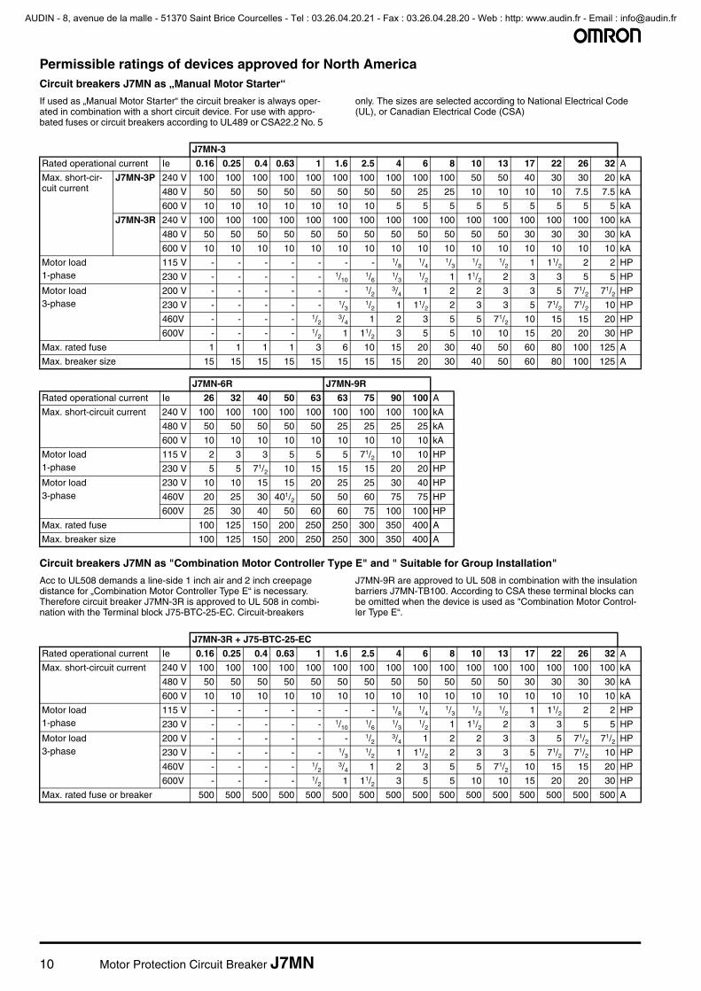
Permissible ratings of devices approved for North AmericaCircuit breakers J7MN as „Manual Motor Starter“
If used as „Manual Motor Starter“ the circuit breaker is always oper-ated in combination with a short circuit device. For use with appro-bated fuses or circuit breakers according to UL489 or CSA22.2 No. 5
only. The sizes are selected according to National Electrical Code (UL), or Canadian Electrical Code (CSA)
Circuit breakers J7MN as "Combination Motor Controller Type E" and " Suitable for Group Installation"
Acc to UL508 demands a line-side 1 inch air and 2 inch creepage distance for „Combination Motor Controller Type E“ is necessary. Therefore circuit breaker J7MN-3R is approved to UL 508 in combi-nation with the Terminal block J75-BTC-25-EC. Circuit-breakers
J7MN-9R are approved to UL 508 in combination with the insulation barriers J7MN-TB100. According to CSA these terminal blocks can be omitted when the device is used as "Combination Motor Control-ler Type E“.
J7MN-3
Rated operational current Ie 0.16 0.25 0.4 0.63 1 1.6 2.5 4 6 8 10 13 17 22 26 32 A
Max. short-cir-cuit current
J7MN-3P 240 V 100 100 100 100 100 100 100 100 100 100 50 50 40 30 30 20 kA
480 V 50 50 50 50 50 50 50 50 25 25 10 10 10 10 7.5 7.5 kA
600 V 10 10 10 10 10 10 10 5 5 5 5 5 5 5 5 5 kA
J7MN-3R 240 V 100 100 100 100 100 100 100 100 100 100 100 100 100 100 100 100 kA
480 V 50 50 50 50 50 50 50 50 50 50 50 50 30 30 30 30 kA
600 V 10 10 10 10 10 10 10 10 10 10 10 10 10 10 10 10 kA
Motor load1-phase
115 V - - - - - - - 1/81/4
1/31/2
1/2 1 11/2 2 2 HP
230 V - - - - - 1/101/6
1/3 1/2 1 11/2 2 3 3 5 5 HP
Motor load3-phase
200 V - - - - - - 1/23/4 1 2 2 3 3 5 71/2 71/2 HP
230 V - - - - - 1/31/2 1 11/2 2 3 3 5 71/2 71/2 10 HP
460V - - - - 1/23/4 1 2 3 5 5 71/2 10 15 15 20 HP
600V - - - - 1/2 1 11/2 3 5 5 10 10 15 20 20 30 HP
Max. rated fuse 1 1 1 1 3 6 10 15 20 30 40 50 60 80 100 125 A
Max. breaker size 15 15 15 15 15 15 15 15 20 30 40 50 60 80 100 125 A
J7MN-6R J7MN-9R
Rated operational current Ie 26 32 40 50 63 63 75 90 100 A
Max. short-circuit current 240 V 100 100 100 100 100 100 100 100 100 kA
480 V 50 50 50 50 50 25 25 25 25 kA
600 V 10 10 10 10 10 10 10 10 10 kA
Motor load1-phase
115 V 2 3 3 5 5 5 71/2 10 10 HP
230 V 5 5 71/2 10 15 15 15 20 20 HP
Motor load3-phase
230 V 10 10 15 15 20 25 25 30 40 HP
460V 20 25 30 401/2 50 50 60 75 75 HP
600V 25 30 40 50 60 60 75 100 100 HP
Max. rated fuse 100 125 150 200 250 250 300 350 400 A
Max. breaker size 100 125 150 200 250 250 300 350 400 A
J7MN-3R + J75-BTC-25-EC
Rated operational current Ie 0.16 0.25 0.4 0.63 1 1.6 2.5 4 6 8 10 13 17 22 26 32 A
Max. short-circuit current 240 V 100 100 100 100 100 100 100 100 100 100 100 100 100 100 100 100 kA
480 V 50 50 50 50 50 50 50 50 50 50 50 50 30 30 30 30 kA
600 V 10 10 10 10 10 10 10 10 10 10 10 10 10 10 10 10 kA
Motor load1-phase
115 V - - - - - - - 1/81/4
1/31/2
1/2 1 11/2 2 2 HP
230 V - - - - - 1/101/6
1/3 1/2 1 11/2 2 3 3 5 5 HP
Motor load3-phase
200 V - - - - - - 1/23/4 1 2 2 3 3 5 71/2 71/2 HP
230 V - - - - - 1/31/2 1 11/2 2 3 3 5 71/2 71/2 10 HP
460V - - - - 1/23/4 1 2 3 5 5 71/2 10 15 15 20 HP
600V - - - - 1/2 1 11/2 3 5 5 10 10 15 20 20 30 HP
Max. rated fuse or breaker 500 500 500 500 500 500 500 500 500 500 500 500 500 500 500 500 A
AUDIN - 8, avenue de la malle - 51370 Saint Brice Courcelles - Tel : 03.26.04.20.21 - Fax : 03.26.04.28.20 - Web : http: www.audin.fr - Email : [email protected]

Motor Protection Circuit Breaker J7MN 11
DescriptionsReleases
Circuit-breakers J7MN are equipped with bimetallic-based, inverse-time delayed overload releases and with instantaneous overcurrent releases (electromagnetic short-circuit releases). The overload releases can be set in accordance with the load current. The over-current releases are permanently set to a value 13 times the rated current and thus enable trouble-free start-up of motors. The scale cover can be sealed to prevent unauthorized adjustments to the set current.
Operating mechanisms
Circuit-breakers J7MN-3P are actuated via a rocker operating mech-anism and circuit-breakers J7MN-3R, J7MN-6R and J7MN-9R via a rotary operating mechanism. An electrical signal can be output, at all Circuit-breakers, via a signalling switch to indicate that the Circuit-breaker has tripped. All operating mechanisms can be locked in the 0 position with a padlock (shackle diameter 3.5 to 4.5 mm). The J7MN Circuit-breakers fulfil the isolation characteristics specified in IEC 60947-2.
Operating conditions
Circuit-breakers J7MN are suitable for use in any climate. They are designed for operation in enclosed rooms under normal conditions (e. g. no dust, corrosive vapours or harmful gases). Suitable enclo-sures must be provided for installation in dusty or damp rooms. Cir-cuit-breakers J7MN can also be fed from below. In order to prevent
premature tripping due to phase failure sensitivity, the three conduct-ing paths must always be uniformly loaded. The conducting paths must be connected in series in the case of single-phase loads.
Short-circuit protection
The short-circuit releases of J7MN circuit-breakers disconnect the faulty load feeder from the system in the event of a short circuit and thus prevent any further damage from being caused. Circuit-breakers with a short-circuit breaking capacity of 50 kA or 100 kA at a voltage of 400 V AC are practically short-circuit-proof at this voltage, as higher short-circuit currents are not usually encountered at the instal-lation point. Back-up fuses are only necessary if the short-circuit cur-rent at the installation point exceeds the rated ultimate short-circuit breaking capacity of the circuit-breakers.
Motor protection
The tripping characteristics of J7MN circuit-breakers are designed mainly to protect three-phase induction motors. The circuit-breakers are therefore also referred to as Manual Motor Starters. The current of the motor to be protected is set with the aid of the scale.
Line protection
J7MN Circuit-breakers for motor protection are also suitable for line protection. The J7MN Circuit-breakers fulfil the isolation conditions of IEC 60 947-3 as well as the additional test conditions for circuit-breakers with isolation characteristics specified in IEC 60947-2. Tak-ing IEC 60 204-1 into consideration, they can thus be implemented as main and EMERGENCY STOP switches. Door-coupling rotary operating mechanism do not fulfil the isolation characteristics.
Wiring diagrams
J7MN-6R J7MN-9R + J77MN-TB100
Rated operational current Ie 26 32 40 50 63 63 75 90 100 A
Max. short-circuit current 240 V 100 100 100 100 100 100 100 100 100 kA
480 V 50 50 50 50 50 40 40 40 40 kA
600 V 10 10 10 10 10 10 10 10 10 kA
Motor load1-phase
115 V 2 3 3 5 5 5 71/2 10 10 HP
230 V 5 5 71/2 10 15 15 15 20 20 HP
Motor load3-phase
230 V 10 10 15 15 20 25 25 30 40 HP
460V 20 25 30 40 50 50 60 75 75 HP
600V 25 30 40 50 60 60 75 100 100 HP
Max. rated fuse or breaker 600 600 600 600 600 1,000 1,000 1,000 1,000 A
Combination Motor Controller Type E
Ratings of auxiliary switches and alarm switches
Lateral auxiliary switch with J77MN-xxS and signalling switch J77MN-T
Transversal auxiliary switch with J77MN-xxF
Breaking capacity A600 A300 AC
Q300 R300 DC
Circuit breakers Traverse Aux. Contact blocks Aux. Contact Block (side mounted)
J7MN J77MN-11F J77MN-20F J77MN-02F J77MN-11S J77MN-20S J77MN-02S
Alarm Switch Undervoltage Release Shunt Release
J77MN-T-11S J77MN-TA-11S/ J77MN-TB-11S
J77MN-U-... J77MN-S-...
AUDIN - 8, avenue de la malle - 51370 Saint Brice Courcelles - Tel : 03.26.04.20.21 - Fax : 03.26.04.28.20 - Web : http: www.audin.fr - Email : [email protected]

12 Motor Protection Circuit Breaker J7MN
DimensionsCircuit-breaker J7MN-3P
Circuit-breaker J7MN-3R
Circuit-breaker J7MN-6R
Circuit-breaker J7MN-9R
Height of arcing spaces (clearance from earthed parts )
at Ue (V) 240 415 460 525 690
mm 20 20 20 20 20
inch 0.8 0.8 0.8 0.8 0.8
Height of arcing spaces (clearance from earthed parts )
at Ue (V) 240 415 460 525 690
mm 30 30 30 30 50
inch 1.18 1.2 1.18 1.18 2
Height of arcing spaces (clearance from earthed parts )
at Ue (V) 240 415 460 525 690
mm 50 50 50 50 50
inch 2 2 2 2 2
Height of arcing spaces (clearance from earthed parts )
at Ue (V) 240 415 460 525 690
mm 50 70 70 110 150
inch 2 2¾ 2¾ 4,33 6
All 1) Side aux. contact2) Magnetic trip alarm3) Shunt or undervoltage release of arcing4) Transverse aux. contact5) 35 mm DIN-rail acc. to EN 50022
3P/3R 6) Push-in Lugs for screw mounting3R/6R/9R 7) Handle lock in OFF-position ( 5 mm)9R 8) 4 mm hexagon socket screw
9) 70 mm DIN-rail acc. to EN 50023
AUDIN - 8, avenue de la malle - 51370 Saint Brice Courcelles - Tel : 03.26.04.20.21 - Fax : 03.26.04.28.20 - Web : http: www.audin.fr - Email : [email protected]

Motor Protection Circuit Breaker J7MN 13
Enclosure J77MN-PF
Door-coupling rotary operating mechanism J77MN-DC
Type A
J77MN-DC-3R-115-B 149-210
J77MN-DC-3R-115-RY 149-210
J77MN-DC-3R-315-B 149-410
J77MN-DC-3R-315-RY 149-410
Type A
J77MN-DC-6R-115-B 194-255
J77MN-DC-6R-115-RY 194-255
J77MN-DC-6R-315-B 194-455
J77MN-DC-6R-315-RY 194-455
Type A
J77MN-DC-9R-115-B 220-282
J77MN-DC-9R-115-RY 220-282
J77MN-DC-9R-315-B 220-482
J77MN-DC-9R-315-RY 220-482
AUDIN - 8, avenue de la malle - 51370 Saint Brice Courcelles - Tel : 03.26.04.20.21 - Fax : 03.26.04.28.20 - Web : http: www.audin.fr - Email : [email protected]

14 Motor Protection Circuit Breaker J7MN
In the interest of product improvement, specifications are subject to change without notice.
ALL DIMENSIONS SHOWN ARE IN MILLIMETERS.
To convert millimeters into inches, multiply by 0.03937. To convert grams into ounces, multiply by 0.03527.
Cat. No. J08E-EN-03B
AUDIN - 8, avenue de la malle - 51370 Saint Brice Courcelles - Tel : 03.26.04.20.21 - Fax : 03.26.04.28.20 - Web : http: www.audin.fr - Email : [email protected]