Ac & Dc Fundamentals-d3
20
Trade of Electrician Standards Based Apprenticeship Introduction to AC Phase 2 Module No. 2.1 Unit No. 2.1.9 COURSE NOTES
-
Upload
obaidur-rehman -
Category
Documents
-
view
226 -
download
1
Transcript of Ac & Dc Fundamentals-d3
7/28/2019 Ac & Dc Fundamentals-d3
http://slidepdf.com/reader/full/ac-dc-fundamentals-d3 1/20
Trade of ElectricianStandards Based Apprenticeship
Introduction to AC
Phase 2
Module No. 2.1
Unit No. 2.1.9
COURSE NOTES
7/28/2019 Ac & Dc Fundamentals-d3
http://slidepdf.com/reader/full/ac-dc-fundamentals-d3 2/20
Created by Gerry Ryan - Galway TC
Revision 1. April 2000 byGerry Ryan - Galway TCJohn Watters - Sligo TC
Revision 2. Nov. 2002 byGerry Ryan - Galway TC
Chris Ludlow - DundalkTC
Revision 3. Aug 2006 by
Chris Ludlow - DundalkTC
Revision 4. Feb 2008 byChris Ludlow - DundalkTC
Published by
FÁS - Training and Employment AuthorityP.O. Box 456
27-33 Upper Baggot StreetDublin 4Ireland
© FÁS - 2008
All rights reserved. No part of this publication may be reproduced, stored in a retrieval system or transmitted in any form or by any means, electronic, mechanical, photocopying, recording or
otherwise, without the prior permission of the copyright owner.
7/28/2019 Ac & Dc Fundamentals-d3
http://slidepdf.com/reader/full/ac-dc-fundamentals-d3 3/20
FÁS Electrical Course Notes - Unit 2.1.9
Table of Contents
INTRODUCTION ......................................................................................................................................... 4
ALTERNATING CURRENT GENERATOR ............................................................................................ 5
GENERATION OF AN ALTERNATING EMF ........................................................................................ 6
FREQUENCY ................................................................................................................................................ 8
AC WAVEFORM VALUES....................................................................................................................... 10
PURELY RESISTIVE AC CIRCUITS ..................................................................................................... 13
ELECTRICITY DISTRIBUTION NETWORK....................................................................................... 19
DIRECT CURRENT ( DC ) GENERATOR ............................................................................................. 20
3 Revision 4. Feb 2008
7/28/2019 Ac & Dc Fundamentals-d3
http://slidepdf.com/reader/full/ac-dc-fundamentals-d3 4/20
FÁS Electrical Course Notes - Unit 2.1.9
Introduction
Welcome to this section of your course, which is designed to introduce you the learner, toAlternating Current theory.
Objectives
By the end of this unit you will be able to:
• Understand the basic principle of a simple AC generator • Understand how an alternating EMF is generated• Explain the term “frequency”• Understand the terms Peak, RMS and Average values of a sine wave• State the effect of a resistor in an AC circuit•
State the effect of a capacitor in an AC circuit• State the effect of an inductor in an AC circuit• List fuels used to generate electricity in Ireland• State ESB distribution network voltages• Understand the basic principle of a simple DC generator
Reasons
Almost all electricity is generated as AC, so it is very important to understand the effects of these components.
4 Revision 4. Feb 2008
7/28/2019 Ac & Dc Fundamentals-d3
http://slidepdf.com/reader/full/ac-dc-fundamentals-d3 5/20
FÁS Electrical Course Notes - Unit 2.1.9
Alternating Current Generator
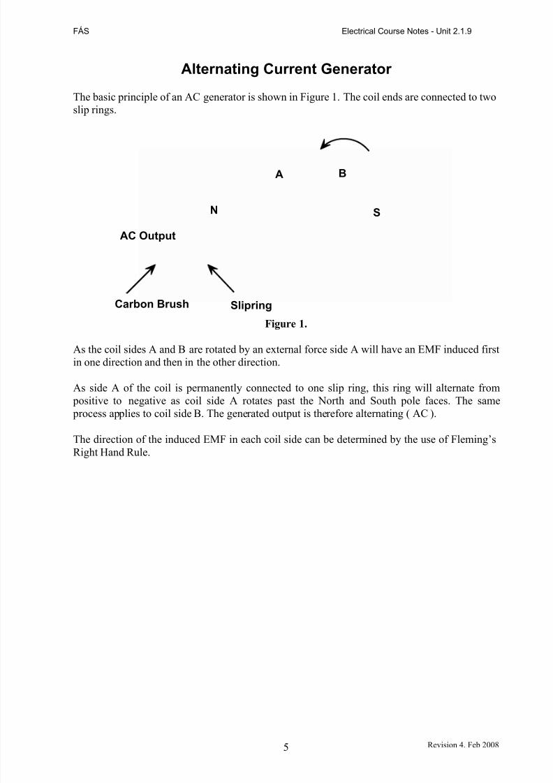
The basic principle of an AC generator is shown in Figure 1. The coil ends are connected to twoslip rings.
A B
N S
AC Output
Carbon Brush Slipring
Figure 1.
As the coil sides A and B are rotated by an external force side A will have an EMF induced firstin one direction and then in the other direction.
As side A of the coil is permanently connected to one slip ring, this ring will alternate from positive to negative as coil side A rotates past the North and South pole faces. The same
process applies to coil side B. The generated output is therefore alternating ( AC ).
The direction of the induced EMF in each coil side can be determined by the use of Fleming’sRight Hand Rule.
5 Revision 4. Feb 2008
7/28/2019 Ac & Dc Fundamentals-d3
http://slidepdf.com/reader/full/ac-dc-fundamentals-d3 6/20
FÁS Electrical Course Notes - Unit 2.1.9
Generation of an Alternating EMF
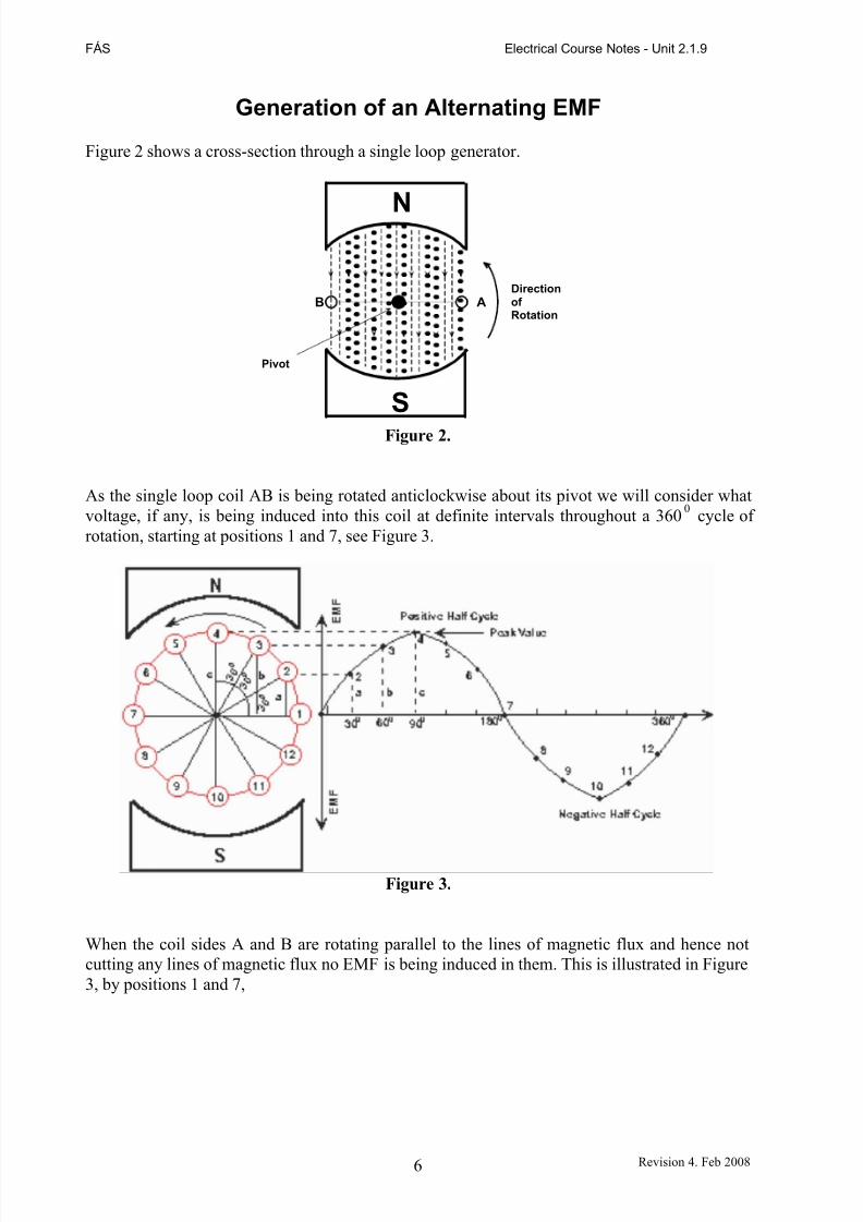
Figure 2 shows a cross-section through a single loop generator.
N
Direction
B A of Rotation
Pivot
SFigure 2.
As the single loop coil AB is being rotated anticlockwise about its pivot we will consider whatvoltage, if any, is being induced into this coil at definite intervals throughout a 3600 cycle of rotation, starting at positions 1 and 7, see Figure 3.
Figure 3.
When the coil sides A and B are rotating parallel to the lines of magnetic flux and hence notcutting any lines of magnetic flux no EMF is being induced in them. This is illustrated in Figure3, by positions 1 and 7,
6 Revision 4. Feb 2008
7/28/2019 Ac & Dc Fundamentals-d3
http://slidepdf.com/reader/full/ac-dc-fundamentals-d3 7/20
FÁS Electrical Course Notes - Unit 2.1.9
As the coil AB is rotated further anticlockwise, it can be seen that the coil is cutting magneticflux lines and hence an EMF is induced into it. This is illustrated in Figure 3, by positions 2 and8. The magnitude of this EMF is as shown at position 2 of the sine wave.
As the coil AB is rotated further anticlockwise through positions 3 and 9, and then to positions4 and 10 where the maximum flux is being cut resulting in the maximum voltage being inducedinto the coil as illustrated at position 4, see Figure 3.
As the induced EMF in the coil AB depends on the amount of flux being cut, which itself depends on the position of the coil, then the magnitude of the induced EMF can be represented
by the coil position.
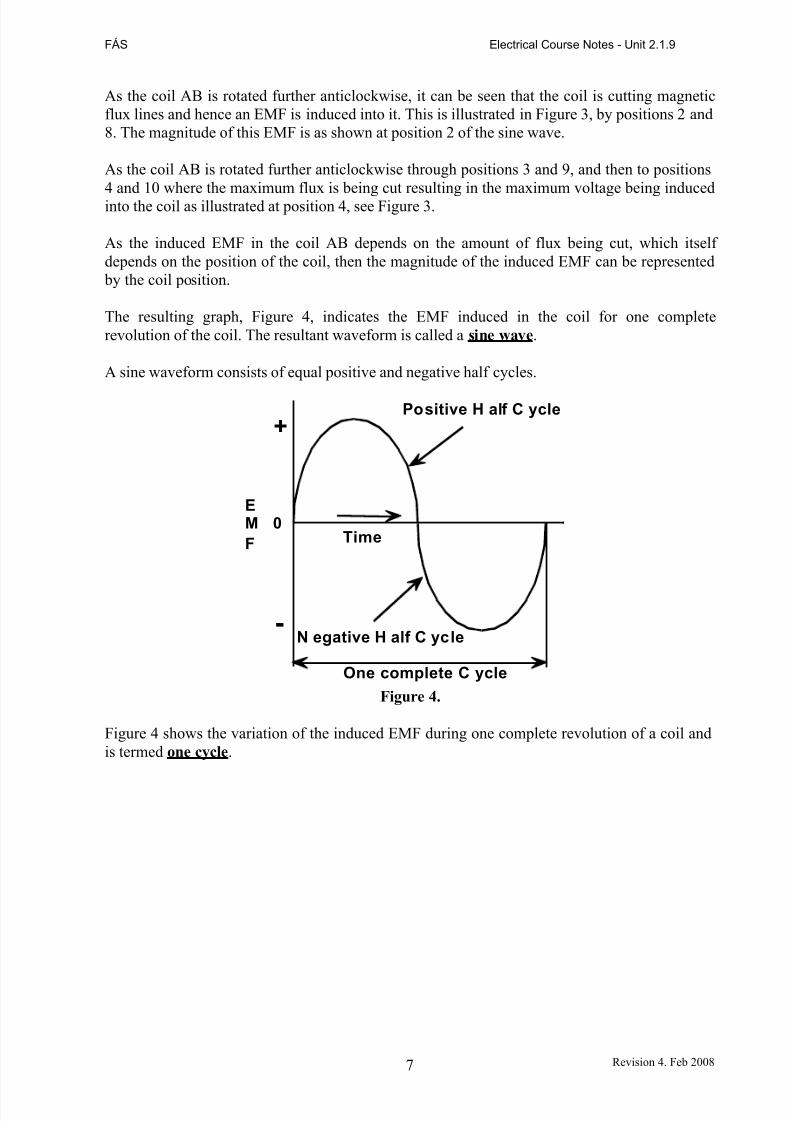
The resulting graph, Figure 4, indicates the EMF induced in the coil for one completerevolution of the coil. The resultant waveform is called a sine w ave.
A sine waveform consists of equal positive and negative half cycles.
Positive H alf C ycle
+
EM 0
F Time
-N egative H alf C ycle
One complete C ycle
Figure 4.
Figure 4 shows the variation of the induced EMF during one complete revolution of a coil andis termed one cycle.
7 Revision 4. Feb 2008
7/28/2019 Ac & Dc Fundamentals-d3
http://slidepdf.com/reader/full/ac-dc-fundamentals-d3 8/20
FÁS Electrical Course Notes - Unit 2.1.9
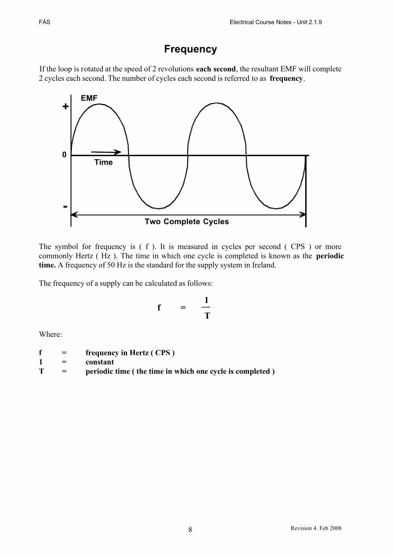
Frequency
If the loop is rotated at the speed of 2 revolutions each second, the resultant EMF will complete2 cycles each second. The number of cycles each second is referred to as frequency.
EMF+
0Time
-
Two Complete Cycles
The symbol for frequency is ( f ). It is measured in cycles per second ( CPS ) or morecommonly Hertz ( Hz ). The time in which one cycle is completed is known as the periodic
time. A frequency of 50 Hz is the standard for the supply system in Ireland.
The frequency of a supply can be calculated as follows:
1f =
T
Where:
f = frequency in Hertz ( CPS )
1 = constant
T = periodic time ( the time in which one cycle is completed )
8 Revision 4. Feb 2008
7/28/2019 Ac & Dc Fundamentals-d3
http://slidepdf.com/reader/full/ac-dc-fundamentals-d3 9/20
FÁS Electrical Course Notes - Unit 2.1.9
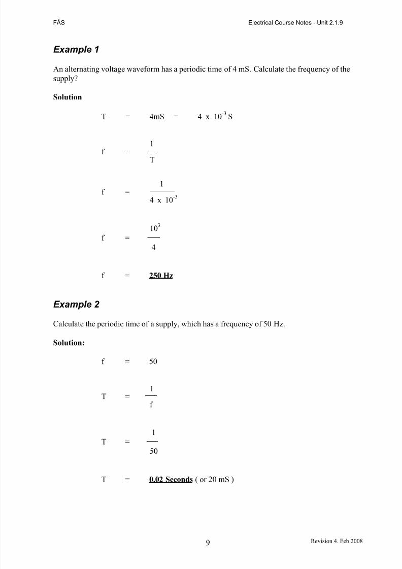
Example 1
An alternating voltage waveform has a periodic time of 4 mS. Calculate the frequency of thesupply?
Solution
T = 4mS = 4 x 10⁻³ S
1f =
T
1f =
4 x 10⁻³
103
f =4
f = 250 Hz
Example 2
Calculate the periodic time of a supply, which has a frequency of 50 Hz.
Solution:
f = 50
1
T = f
1T =
50
T = 0.02 Seconds ( or 20 mS )
9 Revision 4. Feb 2008
7/28/2019 Ac & Dc Fundamentals-d3
http://slidepdf.com/reader/full/ac-dc-fundamentals-d3 10/20
FÁS Electrical Course Notes - Unit 2.1.9
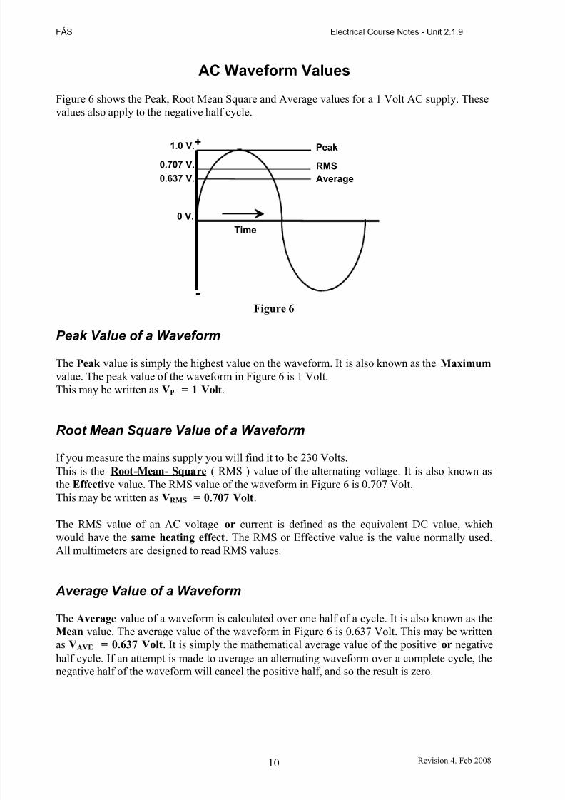
AC Waveform Values
Figure 6 shows the Peak, Root Mean Square and Average values for a 1 Volt AC supply. Thesevalues also apply to the negative half cycle.
1.0 V.+
0.707 V.
0.637 V.
Peak
RMS
Average
0 V.
Time
-Figure 6
Peak Value of a Waveform
The Peak value is simply the highest value on the waveform. It is also known as the Maximum
value. The peak value of the waveform in Figure 6 is 1 Volt.This may be written as VP = 1 Volt.
Root Mean Square Value of a Waveform
If you measure the mains supply you will find it to be 230 Volts.This is the Root-Mean- Square ( RMS ) value of the alternating voltage. It is also known asthe Effective value. The RMS value of the waveform in Figure 6 is 0.707 Volt.This may be written as VRMS = 0.707 Volt.
The RMS value of an AC voltage or current is defined as the equivalent DC value, whichwould have the same heating effect. The RMS or Effective value is the value normally used.All multimeters are designed to read RMS values.
Average Value of a Waveform
The Average value of a waveform is calculated over one half of a cycle. It is also known as theMean value. The average value of the waveform in Figure 6 is 0.637 Volt. This may be writtenas VAVE = 0.637 Volt. It is simply the mathematical average value of the positive or negativehalf cycle. If an attempt is made to average an alternating waveform over a complete cycle, thenegative half of the waveform will cancel the positive half, and so the result is zero.
10 Revision 4. Feb 2008
7/28/2019 Ac & Dc Fundamentals-d3
http://slidepdf.com/reader/full/ac-dc-fundamentals-d3 11/20
FÁS Electrical Course Notes - Unit 2.1.9
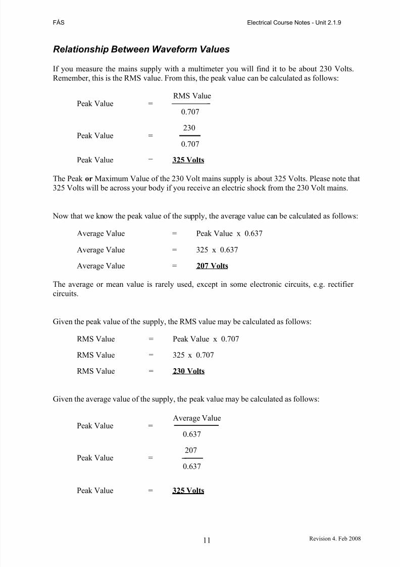
Relationship Between Waveform Values
If you measure the mains supply with a multimeter you will find it to be about 230 Volts.Remember, this is the RMS value. From this, the peak value can be calculated as follows:
Peak Value =
Peak Value =
RMS Value0.707
230
0.707
Peak Value = 325 Volts
The Peak or Maximum Value of the 230 Volt mains supply is about 325 Volts. Please note that325 Volts will be across your body if you receive an electric shock from the 230 Volt mains.
Now that we know the peak value of the supply, the average value can be calculated as follows:
Average Value = Peak Value x 0.637
Average Value = 325 x 0.637
Average Value = 207 Volts
The average or mean value is rarely used, except in some electronic circuits, e.g. rectifier circuits.
Given the peak value of the supply, the RMS value may be calculated as follows:
RMS Value = Peak Value x 0.707
RMS Value = 325 x 0.707
RMS Value = 230 Volts
Given the average value of the supply, the peak value may be calculated as follows:
Peak Value =
Peak Value =
Average Value
0.637
207
0.637
Peak Value = 325 Volts
11 Revision 4. Feb 2008
7/28/2019 Ac & Dc Fundamentals-d3
http://slidepdf.com/reader/full/ac-dc-fundamentals-d3 12/20
FÁS Electrical Course Notes - Unit 2.1.9
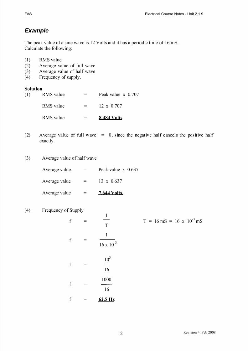
Example
The peak value of a sine wave is 12 Volts and it has a periodic time of 16 mS.Calculate the following:
(1) RMS value(2) Average value of full wave(3) Average value of half wave(4) Frequency of supply.
Solution
(1) RMS value = Peak value x 0.707
RMS value = 12 x 0.707
RMS value = 8.484 Volts
(2) Average value of full wave = 0, since the negative half cancels the positive half exactly.
(3) Average value of half wave
Average value = Peak value x 0.637
Average value = 12 x 0.637
Average value = 7.644 Volts.
(4) Frequency of Supply1
f = T = 16 mS = 16 x 10-3 mST
1f =
16 x 10-3
103
f =16
1000f =
16
f = 62.5 Hz
12 Revision 4. Feb 2008
7/28/2019 Ac & Dc Fundamentals-d3
http://slidepdf.com/reader/full/ac-dc-fundamentals-d3 13/20
FÁS Electrical Course Notes - Unit 2.1.9
Purely Resistive AC Circuits
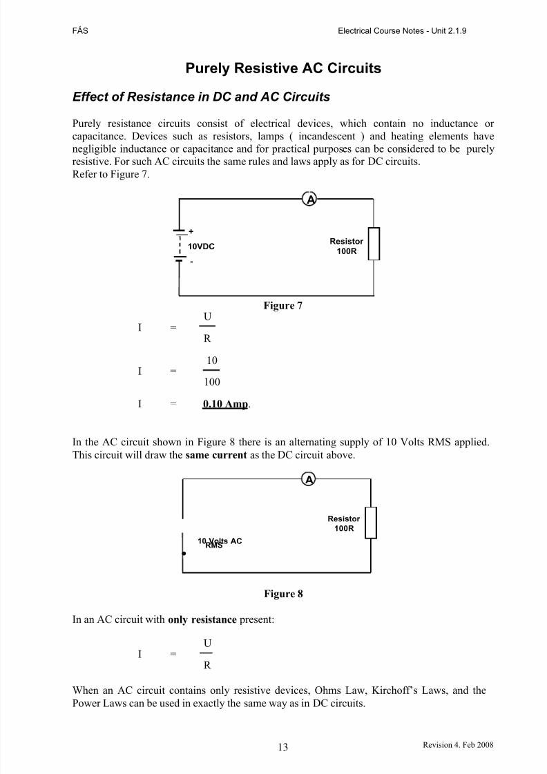
Effect of Resistance in DC and AC Circuits
Purely resistance circuits consist of electrical devices, which contain no inductance or
capacitance. Devices such as resistors, lamps ( incandescent ) and heating elements havenegligible inductance or capacitance and for practical purposes can be considered to be purelyresistive. For such AC circuits the same rules and laws apply as for DC circuits.Refer to Figure 7.
A
+
10VDC
-
Resistor
100R
UI =
R
10I =
100
Figure 7
I = 0.10 Amp.
In the AC circuit shown in Figure 8 there is an alternating supply of 10 Volts RMS applied.This circuit will draw the same current as the DC circuit above.
.10 Volts ACRMS
A
Resistor
100R
Figure 8
In an AC circuit with only resistance present:
UI =
R
When an AC circuit contains only resistive devices, Ohms Law, Kirchoff’s Laws, and thePower Laws can be used in exactly the same way as in DC circuits.
13 Revision 4. Feb 2008
7/28/2019 Ac & Dc Fundamentals-d3
http://slidepdf.com/reader/full/ac-dc-fundamentals-d3 14/20
FÁS Electrical Course Notes - Unit 2.1.9
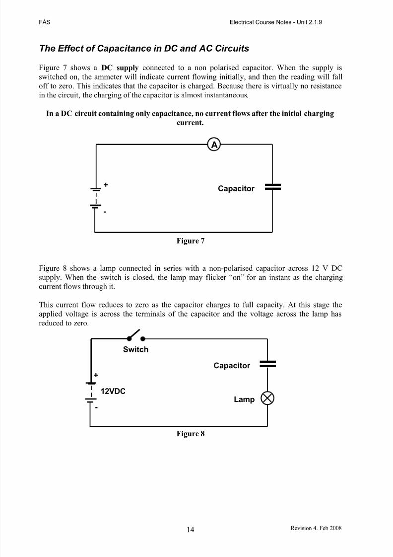
The Effect of Capacitance in DC and AC Circuits
Figure 7 shows a DC supply connected to a non polarised capacitor. When the supply isswitched on, the ammeter will indicate current flowing initially, and then the reading will falloff to zero. This indicates that the capacitor is charged. Because there is virtually no resistance
in the circuit, the charging of the capacitor is almost instantaneous.
In a DC circuit containing only capacitance, no current flows after the initial charging
current.
A
+ Capacitor
-
Figure 7
Figure 8 shows a lamp connected in series with a non-polarised capacitor across 12 V DCsupply. When the switch is closed, the lamp may flicker “on” for an instant as the chargingcurrent flows through it.
This current flow reduces to zero as the capacitor charges to full capacity. At this stage theapplied voltage is across the terminals of the capacitor and the voltage across the lamp hasreduced to zero.
Switch
+
12VDC
-
Capacitor
Lamp
Figure 8
14 Revision 4. Feb 2008
7/28/2019 Ac & Dc Fundamentals-d3
http://slidepdf.com/reader/full/ac-dc-fundamentals-d3 15/20
FÁS Electrical Course Notes - Unit 2.1.9
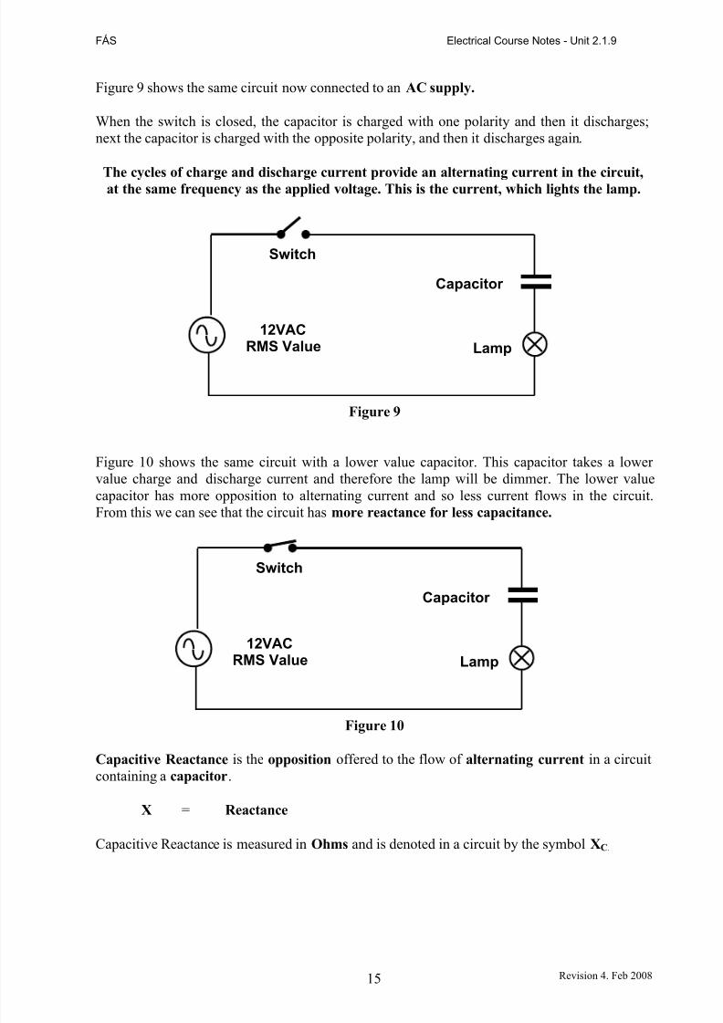
Figure 9 shows the same circuit now connected to an AC supply.
When the switch is closed, the capacitor is charged with one polarity and then it discharges;next the capacitor is charged with the opposite polarity, and then it discharges again.
The cycles of charge and discharge current provide an alternating current in the circuit,at the same frequency as the applied voltage. This is the current, which lights the lamp.
Switch
Capacitor
12VACRMS Value Lamp
Figure 9
Figure 10 shows the same circuit with a lower value capacitor. This capacitor takes a lower value charge and discharge current and therefore the lamp will be dimmer. The lower valuecapacitor has more opposition to alternating current and so less current flows in the circuit.From this we can see that the circuit has more reactance for less capacitance.
Switch
Capacitor
12VACRMS Value Lamp
Figure 10
Capacitive Reactance is the opposition offered to the flow of alternating current in a circuitcontaining a capacitor.
X = Reactance
Capacitive Reactance is measured in Ohms and is denoted in a circuit by the symbol XC.
15 Revision 4. Feb 2008
7/28/2019 Ac & Dc Fundamentals-d3
http://slidepdf.com/reader/full/ac-dc-fundamentals-d3 16/20
FÁS Electrical Course Notes - Unit 2.1.9
Summary:
• When DC is applied to a circuit containing a capacitor in series with a lamp, thecapacitor acts, as a blocking device and the lamp does not light.
•
When AC is applied to a circuit containing a capacitor in series with a lamp, thecapacitor allows current to flow through the process of charging and discharging thecapacitor and as a result the lamp illuminates.
• In an AC circuit containing a capacitor, the lower the capacitance value the lower thecurrent flow. This means that, the lower the capacitor value, the greater the oppositionto current flow. This opposition is known as Capacitive Reactance ( XC ).
• A discharged capacitor behaves like a closed switch.
• A charged capacitor behaves like an open switch.
16 Revision 4. Feb 2008
7/28/2019 Ac & Dc Fundamentals-d3
http://slidepdf.com/reader/full/ac-dc-fundamentals-d3 17/20
FÁS Electrical Course Notes - Unit 2.1.9
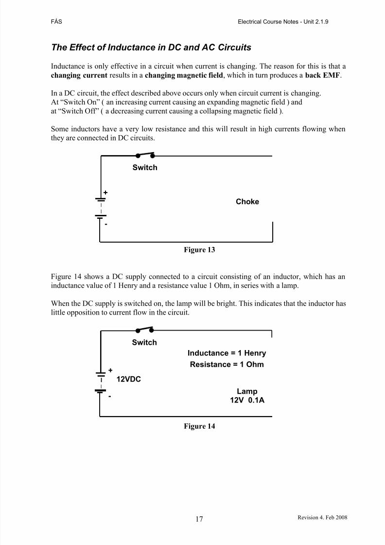
The Effect of Inductance in DC and AC Circuits
Inductance is only effective in a circuit when current is changing. The reason for this is that achanging current results in a changing magnetic field, which in turn produces a back EMF.
In a DC circuit, the effect described above occurs only when circuit current is changing.At “Switch On” ( an increasing current causing an expanding magnetic field ) andat “Switch Off” ( a decreasing current causing a collapsing magnetic field ).
Some inductors have a very low resistance and this will result in high currents flowing whenthey are connected in DC circuits.
Switch
+Choke
-
Figure 13
Figure 14 shows a DC supply connected to a circuit consisting of an inductor, which has an
inductance value of 1 Henry and a resistance value 1 Ohm, in series with a lamp.
When the DC supply is switched on, the lamp will be bright. This indicates that the inductor haslittle opposition to current flow in the circuit.
Switch
+
12VDC
-
Inductance = 1 Henry
Resistance = 1 Ohm
Lamp12V 0.1A
Figure 14
17 Revision 4. Feb 2008
7/28/2019 Ac & Dc Fundamentals-d3
http://slidepdf.com/reader/full/ac-dc-fundamentals-d3 18/20
FÁS Electrical Course Notes - Unit 2.1.9
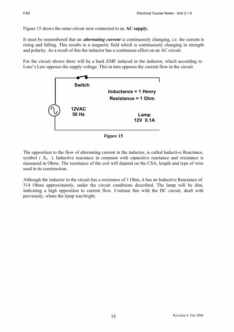
Figure 15 shows the same circuit now connected to an AC supply.
It must be remembered that an alternating current is continuously changing, i.e. the current isrising and falling. This results in a magnetic field which is continuously changing in strengthand polarity. As a result of this the inductor has a continuous effect on an AC circuit.
For the circuit shown there will be a back EMF induced in the inductor, which according toLenz’s Law opposes the supply voltage. This in turn opposes the current flow in the circuit.
Switch
12VAC
50 Hz
Inductance = 1 Henry
Resistance = 1 Ohm
Lamp12V 0.1A
Figure 15
The opposition to the flow of alternating current in the inductor, is called Inductive Reactance,symbol ( XL ). Inductive reactance in common with capacitive reactance and resistance ismeasured in Ohms. The resistance of the coil will depend on the CSA, length and type of wireused in its construction.
Although the inductor in the circuit has a resistance of 1 Ohm, it has an Inductive Reactance of 314 Ohms approximately, under the circuit conditions described. The lamp will be dim,indicating a high opposition to current flow. Contrast this with the DC circuit, dealt with
previously, where the lamp was bright.
18 Revision 4. Feb 2008
7/28/2019 Ac & Dc Fundamentals-d3
http://slidepdf.com/reader/full/ac-dc-fundamentals-d3 19/20
FÁS Electrical Course Notes - Unit 2.1.9
Electricity Distribution Network
The Electricity Supply Board ( ESB ) operates 19 major power stations and is responsible for the generation, transmission and distribution of electricity in Ireland. The ESB is also thelargest provider of renewable power, with hydro-electric power stations on the Erne, the
Shannon, the Lee and the Liffey. A wholly-owned subsidiary of ESB, Hibernian Wind, isdeveloping and operating wind farms.
Generation of Electricity
Many types of fuel are used to create steam and rotate turbines, which are coupled to 3-PhaseAC generators. These generators produce electricity at 10,000 Volts ( 10kV ) 50 Hz.
A sample of the range of energy sources used by ESB generating stations is as follows:
• Coal ( Moneypoint )• Gas ( Aghada )• Hydro ( Ard na Chrusha )• Oil ( Tarbert )• Oil / Gas ( Poolbeg )• Peat ( Shannonbridge )• Pumped Storage ( Turlough Hill )
Distribution of Electricity
The National Grid is an electricity transmission network of lines and cables throughout thecountry. It operates at very high voltages ( up to 400,000 Volts ).
At power stations, electricity is transformed to the higher voltage levels of 110,000, 220,000, or 400,000 Volts. It is then fed into a transmission network of approximately 6,000km of overheadlines and underground cables. These cables carry the electricity throughout the country. Thisnetwork incorporates over one hundred high voltage transformer stations. At these stations thevoltage is reduced to distribution voltages of 38,000, 20,000 and 10,000 Volts. Some larger industrial premises are supplied directly at these voltages.
Electricity is distributed at these 'medium' level voltages over an extensive distribution network of 80,000km of overhead lines and underground cables to smaller local substations close tocustomers' premises. At the local substations, it is finally transformed down to the normalmains voltage level for use by customers.
By using very high voltages, the amount of energy that is wasted as heat, due to resistance inthe transmission cables is greatly reduced. For every doubling of the transmission voltage, theamount of power wasted, is reduced by 75%.
19 Revision 4. Feb 2008
7/28/2019 Ac & Dc Fundamentals-d3
http://slidepdf.com/reader/full/ac-dc-fundamentals-d3 20/20
FÁS Electrical Course Notes - Unit 2.1.9
Direct Current ( DC ) Generator
The basic difference between the AC generator and the DC generator is the way the generatedEMF and current are extracted from the rotating coil, which cuts the magnetic field. In the caseof the AC generator the induced EMF is extracted via fixed carbon brushes in contact with the
rotating slip rings. In the case of the DC generator, the induced EMF is extracted via fixedcarbon brushes in contact with the rotating commutator, as shown in Figure 18. A simple DCgenerator as shown, has a single loop coil with its ends connected to two copper segmentsforming its commutator which is mounted on a shaft.
Figure 18
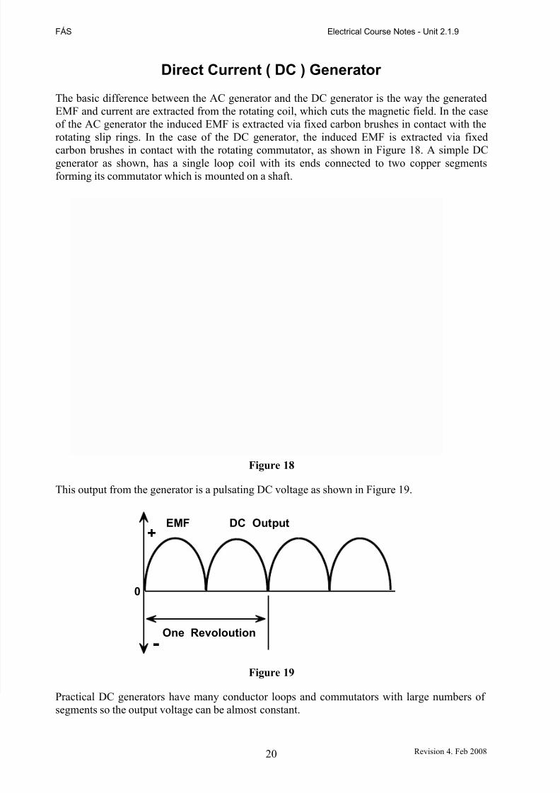
This output from the generator is a pulsating DC voltage as shown in Figure 19.
EMF DC Output+
0
One Revoloution
-
Figure 19
Practical DC generators have many conductor loops and commutators with large numbers of segments so the output voltage can be almost constant.