AC-3 Encoders
39
Comparative Study of Analysis Filter Bank Designs for AC-3 Encoding Undergraduate Student Project Mark Joseph L. Tan 2002-22034 B.S. Computer Engineering Adviser Franz A. de Leon, MS EE University of the Philippines, Diliman
-
Upload
mark-joseph-l-tan -
Category
Engineering
-
view
216 -
download
1
Transcript of AC-3 Encoders

Comparative Study of Analysis Filter Bank Designs for AC-3 Encoding
Undergraduate Student Project
Mark Joseph L. Tan
2002-22034
B.S. Computer Engineering
Adviser
Franz A. de Leon, MS EE
University of the Philippines, Diliman

Approval Sheet In partial fulfillment of the requirements for the degree of Bachelor of Science in
Computer Engineering, this project entitled “Comparative Study of Analysis Filter Bank
Designs for AC-3 Encoding” prepared and submitted by Mark Joseph L. Tan, is hereby
recommended for approval.
__________________
Franz de Leon
Adviser
Accepted in partial fulfillment of the requirements for the degree of Bachelor of
Science in Computer Engineering
Approved by:
__________________
Panel
__________________
Panel
__________________
Reader
__________________
EEE190 Handler

Abstract
Several high-fidelity digital audio formats have been developed with the challenge of
developing audio coding techniques intended for low cost, limited bandwidth and storage
capacity.
AC-3 is one of these international standards. It has been widely used as the audio
coding standard for laserdiscs, cinemas and DVD films. AC-3 has been accepted by the
Advanced Television Systems Committee (ATSC) as the audio coding standard for US
Grand Alliance High Definition Television (HDTV) system.
This project is a comparative study of analysis filter bank designs for AC-3 encoding.
The standard algorithm will first be implemented in stereo mode using software.
Different optimization techniques on the analysis filter bank designs will then be
performed. Finally, listening and speed performance tests will be done to compare the
optimized codes with the standard implementation.
The project will aid in future designs concerning the AC-3 audio coding standard,
with the goal of improving performance and efficiency for high-quality digital audio
compression.

Table of Contents
1. Introduction
1.1. Background of the Project
1.2. Project Objectives
1.3. Overview
2. Literature Review
2.1. Standard Digital Audio Format
2.1.1. Standard Formatss
2.1.2. MPEG-Based Proprietary Formats
2.1.3. Non-MPEG Proprietary Formats
2.2. AC-3 Audio Coding Standard
2.2.1. History and Development
2.2.2. AC-3 Compression Features
2.2.3. AC-3 Comparative Advantages
2.2.4. AC-3 Bit Stream
2.3. AC-3 Encoding Algorithm
2.3.1. Analysis Filter Bank
2.3.2. Spectral Envelope Encoding
2.3.3. Encode Bit Allocation
2.3.4. Mantissa Quantization
2.3.5. Frame Formatting and Bit Stream Packing
2.4. AC-3 Decoding Algorithm
2.4.1. Frame De-Formatting and Bit Stream Unpacking
2.4.2. Spectral Envelope Decoding
2.4.3. Decode Bit Allocation
2.4.4. Mantissa De-Quantization
2.4.5. Synthesis Filter Bank using IMDCT
2.5 Related Works
2.5.1 The ATSC Standard
2.5.2 FFmpeg Multimedia System
3 Methodology
3.1 Design
3.1.1 Direct Method
3.1.2 Indirect Method using DCT-IV
3.1.3 Indirect Method using FFT
3.1.4 Recursive Method
3.2 Implementation
3.3 Testing
3.3.1 Preliminary Test
3.3.2 Objective Tests
3.3.3 Formal Listening Test
3.3.4 Playback
3.3.5 Listening Conditions
4 Results and Analysis
4.1 Objective Measurements

Chapter 1
Introduction
Digital Audio Compression (AC-3) is the 3
rd generation audio coding algorithm
developed by the Digital coder group at Dolby Laboratories which eventually became the
audio coding standard for the US Grand Alliance HDTV system. The primary motivation
in developing the AC-3 audio coding standard was the need for a superior multi-channel
audio coder. AC-3 became one of the most successful proprietary digital audio formats
available in the market. It is usually integrated with video applications and is rarely used
as stand alone. Thus, even though it has been around since 1990’s, it is not as prominent
as the other consumer audio formats such as MPEG Layer III (mp3).
AC-3 has a wide variety of applications. It can found in laserdiscs, digital cable
and even satellite transmissions. But it is famous for being the audio format used in
cinemas and DVD’s. Like other popular codecs, it has a perceptual coding algorithm that
uses minimal digital information and lower data rates which allows minimum
degradation of quality. Thus, the sound almost exactly the same as the original sound
when decoded for playback providing true surround.
Currently, there are several audio decoders that are capable of AC-3 playback.
However, it is very rare to find audio encoders and decoders that are solely dedicated to
handling the AC-3 format.
1.1 Background of the Project
Figure 1-1 Project Overview
The project is a comparative study of the analysis filter bank designs for the AC-3
encoding which will be subdivided into two major parts. The first part would be the
software development of the AC-3 audio coding standard’s encoding algorithm while the
second part would be the implementation of analysis filter bank designs that will modify
the traditional algorithm. The project overview is shown in Figure 1-1.
Traditional
Encoding Algorithm
Modified Encoding
Algorithms
Final
Code Comparative
Analysis Objective
Analysis
For the development of AC-3 encoding algorithm, each of the different coding
blocks of this audio format will be identified, implemented and tested. Modification will
then be carried out in order decrease the amount of computations, thus, minimizing the
complexity. This will be verified by testing procedures which will include listening tests
to assess the quality of the audio file and tests to verify computational complexity.
The implementation of the encoding algorithm as well as the optimization
techniques will be based on various researches that deal with the AC-3 audio coding
standard.
1.2 Project Objectives
One of the major factors considered in creating perceptual audio coders is the
need for real-time processing. The speed of the encoding algorithm is directly related to
the computational complexity and the number of cycles it takes to process an audio
block. Since a large part of the calculation occurs in the filter bank, the interest of the
project lies on having a comparative analysis of different filter bank designs for the AC-3
encoding algorithm.
This will be done by implementing each block of the coding process to create an
encoder that operates in stereo mode and applying different methods for optimizing the
performance. The project aims to optimize a traditional AC-3 encoding algorithm to
reduce its computational complexity.
Lastly, it is of great importance to characterize AC-3 compression features since
this will be the first AC-3 related project to be conducted by DSP Laboratory. The project
aims to look into particular AC-3 features that make it one of the most powerful
perceptual audio standards.
1.3 Overview
The components of the AC-3 encoding algorithm can be grouped into five major
blocks. These are the: (1) analysis filter banks which perform the time-frequency
transformation of the input signal, (2) spectral envelope encoding where the power
spectral density is analyzed, (3)-(4) bit allocation and mantissa quantization that use
psychoacoustic models to manipulate the mantissa component of the input signal and (5)
formatting & bit stream packing that prepares the audio data for encoding. [1]
Several of the AC-3 related studies that have been carried out focused on
implementing the encoding algorithm and improving its performance such as those in [8]
[11] [12]. The emphasis of the optimization methods have been put mainly on the
analysis filter bank which aims to minimize complexity by decreasing the number of
computations needed by the encoding algorithm. This is because it is one of the most
calculation intensive processes in the algorithm. Thus, this project will compare the
optimization methods on the analysis filter bank design.
The project will be an implementation of the AC-3 audio coding standard’s
encoding algorithm using software. The entire standard algorithm along with the analysis
filter bank designs will be implemented using the C/C++ programming language.
Testing will be done using two methods, first would be objective tests that will
measure accuracy and speed to check the number of computations made. Second would
be subjective audio listening tests to examine quality and check if there are noticeable
differences on the generated AC-3 audio format.

Chapter 2
Literature Review
2.1 Standard Digital Audio Formats
The introduction of the audio compact disc (CD) technology in 1982 set off the
transformation of audio media from analog to digital format. The single purpose of CD
back then was to hold music in digital form. However, huge amount of data is required to
represent the digital audio file which made it necessary to develop audio coding
techniques for efficient transmission and storage. [1]
The goal of these coding techniques is to efficiently use the least amount of bits to
represent a digital audio file without making any obvious changes in the original data
through transparent coding. Audio coding technology has experienced tremendous
development that it has become possible to successfully remove as much as 90% of audio
data during compression without noticeable changes in the original from.
There are several international and commercially available audio coding standards
which can loosely be classified as Standard Formats, MPEG-Based Proprietary Formats,
and Non-MPEG Proprietary Formats. Table 2-1 shows some examples of each. [2]
Standard Formats MPEG-Based
Proprietary Formats
Non-MPEG
Proprietary Formats
Pulse Code Modulation (PCM) AT&T’s a2b AC-3
Differential PCM MP4 EPAC
Adaptive Differential PCM Liquid Audio Windows Media Audio (WMA)
u-law Compression Apple QuickTime Real Audio
ISO/MPEG Family Transparent Audio Compression (TAC)
TwinVQ (VQF)
Table 2-1 – Audio Coding Standards
2.1.1. Standard Formats
PCM is a type of format that can be read by several audio applications. DPCM,
APCM and u-law compressions are simple variations of lossy compression formats that
store only the difference between consecutive samples instead of the entire information.
[2]
The Moving Pictures Experts Groups (MPEG) under the International
Organization for Standardization (ISO) has developed several standards under the
ISO/MPEG Family. These include the MPEG-1 Layers I, II, and III - which can operate
in mono or stereo modes; MPEG-2 Layers I, II, III, and AAC - which can operate in
multi-channel; and MPEG-4 – which can operate in multi-channels low-bit rates.

2.1.2. MPEG-Based Proprietary Formats
The ISO/MPEG Family consists of notable open standards which have become
widely used. Because of this, several proprietary formats have been developed which are
MPEG-based. These enhancements in the ISO/MPEG standards paved way for the
development of sophisticated audio formats that support several features. [2]
2.1.3. Non-MPEG Proprietary Formats
There are also several Non-MPEG Proprietary Formats available in the market.
These formats offer a wide array of applications and claim to produce quality audio
sound that is indistinguishable from the original CD. Among all of these, AC-3 has
emerged to be the de facto standard found on the latest generation of laserdiscs, cinemas,
and DVD films because of its audio coding technique that makes it capable of delivering
high-fidelity audio content. [2]
2.2 AC-3 Audio Coding Standard 2.2.1. History and Development
In 1987, the Federal Communications Commission (FCC) formed the Advisory
Committee on Advanced Television Service (ACATS) in the United States.[6] ACATS
formally started the High Definition Television (HDTV) standardization process with the
aim of creating a an excellent multi-channel audio format for HDTV sound.
Dolby AC-1, a low-cost delta-modulation based coding technology was
developed. By 1989, advances in the audio coding technology allowed the development
of AC-2, a higher quality audio coding standard with reduced bit-rate. [6]
A real-time implementation of AC-3 was first conducted in multiple DSP cards.
By 1991, Star Trek VI became the first AC-3 encoded film. This multi-channel audio
compression standard was accepted by ATSC in 1994.
2.2.2. AC-3 Compression Features
One of the key features of the AC-3 audio standard is the use some very
sophisticated psychoacoustic models which allow channels to be combined and
separated. By using a global bit allocation technique, it allows for any channel to borrow
bits which are not being used.
It has been designed to take maximum advantage of human auditory masking in
that it divides the audio spectrum of each channel into narrow frequency bands of
different sizes optimized with respect to the frequency selectivity of human hearing. This
makes it possible to sharply filter coding noise so that it is forced to stay very close in
frequency to the frequency components of the audio signal being coded. By reducing or

eliminating coding noise wherever there are no audio signals to mask it, the sound quality
of the original signal can be subjectively preserved. [3]
AC-3 provides only full range channels so the sounds are much better in terms of
quality and allows monophonic up to 5.1 audio channels to provide the necessary
channels needed for a digital film audio system. The configuration for a 5.1 channel setup
is composed of five full bandwidth channels: Left, Right, Left Surround, Right Surround,
Center, and the Subwoofer is shown in Figure 2-1. Details of the AC-3 audio coding
standard are also shown in the table below. [4]
Figure 2-1 – AC-3 5.1 channel configuration
General Characteristics of AC-3 Audio Standard
Sample frequency 32 kHz, 44.1kHz, 48 kHz
Bit Depth 16 – 24 bits
Bit Rate (B) 32 – 640 kbps
Frame Size 1536 samples
Compression 10:1
DVD Characteristics of AC-3 Audio Standard
Maximum Sampling Frequency 192 kHz
Maximum Samples per second 192,000
Maximum Bit Depth 24-bits
Table 2-2 – AC-3 Characteristics
2.2.3. AC-3 Comparative Advantages
Evaluating audio compression is complicated because there is no objective quality
parameter. Instead, comparison of AC-3 with two other popular digital audio formats, CD
Quality (PCM) and MPEG Layer III (MP3) is shown in the Table 2-3.
RIGHT
SURROUND
LEFT
SURROUND
RIGHT LEFT
CENTER
(SUBWOOFER)

CD Quality MPEG Layer III* AC-3*
Precision Sampling Accuracy
(Bits/sample/channel)
16-bit 16-bit 24-bit
Gradiation Levels 65,536 65,536 16,777,216
Rate Sampling Rate ( Freq ) 44.1kHz 44.1 kHz 96 kHz
Samples per second 44,100 44,100 96,000
Bit Rate in bits/sec 1,411,200 128,000 192,000
Bit Rate in Kbytes/sec 176 16 24
Size MB/min 10 1 1.5
Compression 1:1 1:12 1:10 * Most commonly used configuration
Table 2-3 - Compares Attributes of AC-3 versus CD audio and MPEG Layer III
Precision values clearly show that AC-3 has a more accurate signal representation
in Figure 2-2. The 24-bit depth allows it to have 256 times more gradiation levels than
the CD quality. Despite of this, AC-3 can still compress audio data by a factor of 10 due
to its very high compression technique. Although this is not evident in stereo mode (since
AC-3 is designed to be most advantageous in multi-channel configurations), its
compression factor is still comparable to MPEG Layer III.
Figure 2-2 – Graphical Comparison of CD Audio with AC-3
2.2.4. AC-3 Bit Stream
An AC-3 Bit Stream is composed of a series of frames representing a constant
time interval of 1536 PCM samples across all coded channels. Each frame is an
independent entity and no data are shared with previous frames aside from the inherent
transform overlap. The frame has a fixed size and depends only on the sample rate and
coded data rate. It consists of 6 audio blocks with 256 samples each. The structures of the
AC-3 Frame and Audio Block are shown in Tables 2-4 and Figure 2-5.
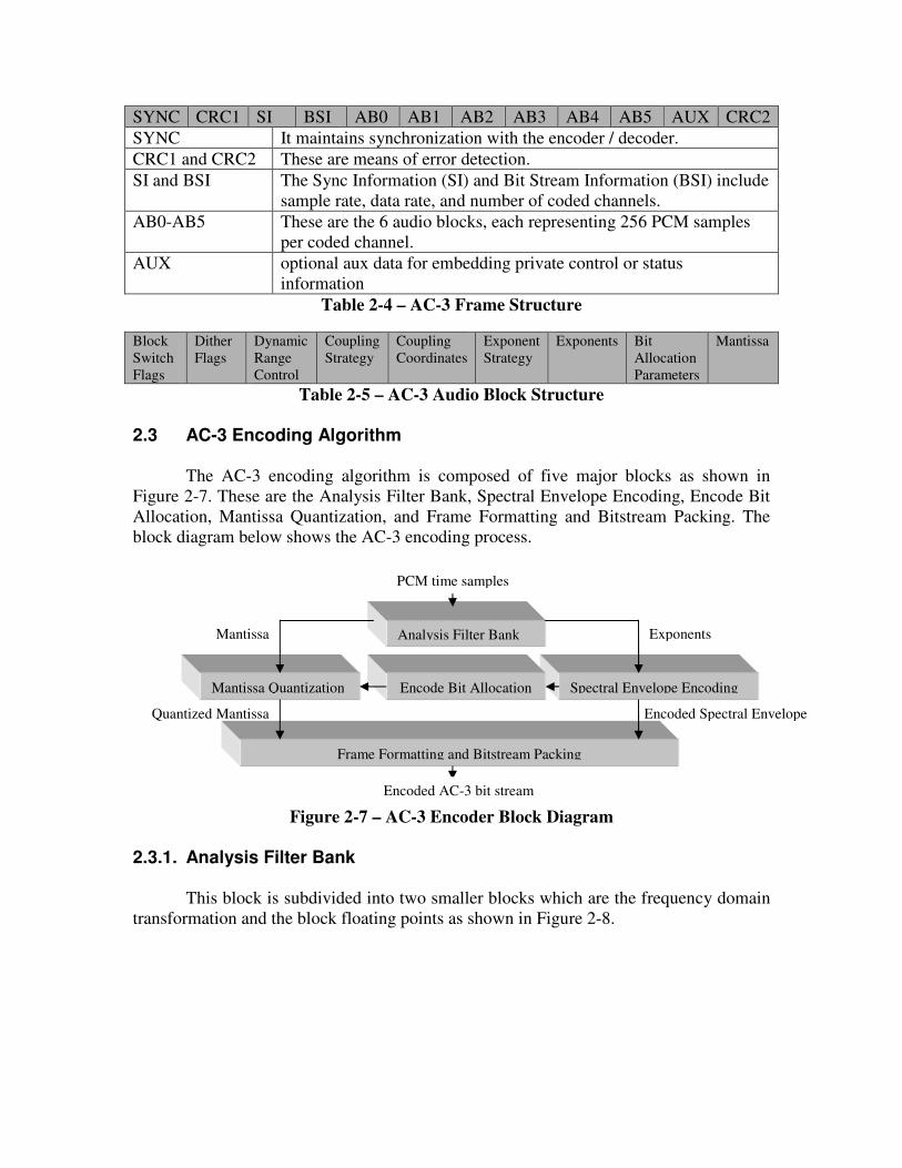
SYNC CRC1 SI BSI AB0 AB1 AB2 AB3 AB4 AB5 AUX CRC2
SYNC It maintains synchronization with the encoder / decoder.
CRC1 and CRC2 These are means of error detection.
SI and BSI The Sync Information (SI) and Bit Stream Information (BSI) include
sample rate, data rate, and number of coded channels.
AB0-AB5 These are the 6 audio blocks, each representing 256 PCM samples
per coded channel.
AUX optional aux data for embedding private control or status
information
Table 2-4 – AC-3 Frame Structure Block
Switch
Flags
Dither
Flags
Dynamic
Range
Control
Coupling
Strategy
Coupling
Coordinates
Exponent
Strategy
Exponents Bit
Allocation
Parameters
Mantissa
Table 2-5 – AC-3 Audio Block Structure
2.3 AC-3 Encoding Algorithm
The AC-3 encoding algorithm is composed of five major blocks as shown in
Figure 2-7. These are the Analysis Filter Bank, Spectral Envelope Encoding, Encode Bit
Allocation, Mantissa Quantization, and Frame Formatting and Bitstream Packing. The
block diagram below shows the AC-3 encoding process.
Figure 2-7 – AC-3 Encoder Block Diagram
2.3.1. Analysis Filter Bank
This block is subdivided into two smaller blocks which are the frequency domain
transformation and the block floating points as shown in Figure 2-8.
Analysis Filter Bank
Mantissa Quantization Spectral Envelope Encoding
Exponents
Encode Bit Allocation
PCM time samples
Frame Formatting and Bitstream Packing
Quantized Mantissa
Mantissa
Encoded Spectral Envelope
Encoded AC-3 bit stream

Figure 2-8 – Analysis Filter Bank Block Diagram
Frequency Domain Transformation using MDCT
The PCM time samples are best examined in the frequency domain due to the
frequency masking properties of human hearing. To transform the signal from a sequence
of PCM time samples to a sequence of frequency coefficient blocks, a 512-point
Modified Discrete Cosine Transform (MDCT) with 50% overlap is first performed.
The result is then multiplied by a time window to transform the input signal to
frequency domain. This MDCT is based on the idea of Time Domain Alias Cancellation
(TDAC) introduced by Princen and Bradley. [11] Normally, the analysis filter bank uses
the 512-point MDCT (long transform). But in the event of transient signals, this method
can be improved by using two 256-point transforms (short transforms) instead.
The 512 x 256 matrix that transforms the 512 windowing samples results in 256
frequency coefficients. The equation of this matrix is shown below:
cos( (2 1)(2 1_ (2 1))1024 4
512 256
nkL n k k
where L x matrix
nk each entry of L
π π+
+
−
< > = + + + +
=
=
The 256 x 128 matrices that transforms the 512 windowing samples results in two
sets of 128 frequency coefficients. The equations of these matrices are shown below:
1
1
1
cos( (2 1)(2 1))512
256 128
nkS n k
where S x matrix
nk each entry of S
π+
+
+
< > = + +
=
=
2
2
2
cos( (2 1)(2 1) (2 1))512 2
256 128
nkS n k k
where S x matrix
nk each entry of S
π π+
+
+
< > = + + + +
=
=
PCM time samples
Analysis Filter Bank
Frequency Domain
Transformation
Block Floating-Point Mantissa Exponent

Block Floating-Point
The input to this block is the set of all transform coefficients that have been
computed in the frequency domain transformation block. The floating point block simply
breaks down each of the frequency transform coefficients into binary exponent and
mantissa parts which will be analyzed separately in the succeeding blocks. [1]
2.3.2. Spectral Envelope Encoding
The Spectral Envelope Encoding involves two main processes, the power spectral
mapping and frequency banding. The exponents are first encoded according to time and
frequency resolution where they are mapped to the power spectrum so that the
computation of this spectrum can be simplified.
The frequency banding then maps the MDCT frequency domain to Fourier
Frequency domain where the psychoacoustic model is used to determine the perceptual
resolution.
Figure 2-9 – Spectral Envelope Encoding Block Diagram
2.3.3. Encode Bit Allocation
The goal of bit-rate reduction is to remove bits from a representation of an audio
signal in a manner that is inaudible to humans. The bit allocation block of the AC-3
coding standard uses the spectral envelope to determine the bit allocation required to
encode the individual mantissa. This block performs a convolution of the power spectral
density with the spreading function matching the ear’s masking curve. The bit allocation
block can be subdivided into smaller blocks as shown in Figure 2-10 below. [1]
Figure 2-10 – Encode Bit Allocation Block Diagram
Bit
Assignment
Transform
Coefficient
Exponents
Spectral Envelope Encoding
Power Spectrum
Mapping
Frequency Banding
Power
Spectral
Density
Encoded Spectral Envelope
Encode Bit Allocation
Spreading
Function
Hearing
Threshold
Masking
Comparison
Power
Spectral
Density

There are two broad classes of bit-allocation strategy. These are the forward
adaptive bit allocation and the backward adaptive bit allocation. AC-3 uses hybrid
forward/backward bit allocation, a fusion of these two methods. [1]
Forward Adaptive Bit Allocation
This is a method where the encoder may precisely calculate an optimum bit
allocation and explicitly code this allocation into the bit stream. It is the most accurate
allocation technique since the encoder has full knowledge of the input signal. Also, since
the psychoacoustic model is in the encoder itself, this can be changed without affecting
the installed encoders. The block diagram is shown in Figure 2-11.
However, there is a need to utilize a portion of the available bit-rate to deliver the
explicit bit allocation to the decoder. Transient conditions require fine time resolution
while steady state conditions require fine frequency resolution. These improved
resolutions require higher allocation in the data rate. Thus, forward adaptive puts
practical limitation on performance at very low bit rates.
Figure 2-11 – Forward Adaptive Bit Allocation Encoder Block Diagram
Backward Adaptive Bit Allocation
This is a method where the encoder calculates bit allocation from the coded audio
data without explicit information from the encoder. It does not require utilization of a
portion of the available bit-rate, thus all of the bits can be allocated to audio coding. It is
more efficient in transmission and allows the bit allocation to have superior time and
frequency resolution. The block diagram is shown in Figure 2-12.
However, the bit allocation must be calculated in the decoder from the
information contained in the bit stream, thus of limited accuracy and may contain small
errors. Also, psychoacoustic model may not be updated since the bit allocation algorithm
in the encoder is fixed.
Bit Allocator
Filter Bank Quantize
Multiplex Input signal
Bit allocation
Coded bit stream

Figure 2-12 - Backward Adaptive Bit Allocation Encoder Block Diagram
Hybrid Forward/Backward Bit allocation
The Hybrid Forward/Backward Bit allocation is the method implemented by the
AC-3 encoding algorithm. It uses the core backward adaptive bit allocation process found
in both the encoder and the decoder. This core routine is accurate and based on the
psychoacoustic model which has assumptions on the masking properties of signals. The
block diagram is shown in Figure 2-13. The input to the core routine is a spectral
envelope which is part of the encoded audio. In AC-3, the spectral envelope has
time/frequency resolution equal to the analysis filter bank.
Figure 2-13 – Hybrid Forward/Backward Bit Allocation Encoder Block Diagram
2.3.4. Mantissa Quantization
The results of the parametric bit allocation model are used along with the raw
mantissa to perform the mantissa quantization. The mantissas are quantized with a
variable number of bits based on the results of the bit allocation block.
The resulting values in this quantization block are not just composed of a
specified number of significant bits. The mantissa values are scaled and offset to provide
zero-centered, equal-width and symmetrical quantization levels. [5]
Encode Spectral Envelope
Filter Bank Quantize
Core Bit Allocator
Input
signal
Bit allocator Multiplex
Bit Allocation
Side Information
Encode
Spectral
Envelope
Filter Bank Quantize
Multiplex
Input
signal
Bit allocator
Encoded Spectral
Envelope Coded
Bit-stream
Quantized
Samples
Coded
Bit-stream

2.3.5. Frame Formatting and Bit Stream Packing
The frame formatting and bit stream packing is the final stage in the AC-3
encoding algorithm. All information in each of the six blocks is placed in a series of array
and scalar values.
This information includes the bit allocation information, exponents, mantissas,
coupling coefficients and dither flags. [5] This data packing stage places all information
in a single block along with all the necessary data such as the synchronization, header,
and wrapper information. The data is coded logically for the decoder to easy unpack the
bit stream data.
2.4 AC-3 Decoding Algorithm
The AC-3 decoding algorithm is composed of five major blocks as shown in
Figure 2-14. The major blocks are basically the same as those in the encoding process
implemented inversely. These are the Frame De-Formatting and Bit Stream Unpacking,
Spectral Envelope Decoding, Decode Bit Allocation, Mantissa De-quantization, and the
Synthesis Filter Bank. The block diagram of the decoding algorithm is shown below:
Figure 2-14 - AC-3 Decoder Block Diagram
2.4.1. Frame De-Formatting and Bit Stream Unpacking
The AC-3 Frame De-Formatting block shown consists of frame synchronization,
error detection and frame de-formatting stages. The frame synchronization ensures that
the decoder maintains the sync with the incoming input data stream. [7] The encoded
digital audio input enters an input buffer before proceeding to the error detection stage.
Each of the decoder input data block is checked in the error detection stage for
consistency. In the case that an error is found and it cannot be resolved, the last known
correct block can be used as a substitute for the erroneous block. The substitution can be
Frame De-Formatting and Bit Stream
Unpacking
Mantissa De-Quantization Spectral Envelope Decoding
Encoded Spectral Envelope
Decode Bit Allocation
Encoded AC-3 bit stream
Synthesis Filter Bank
Mantissa
Quantized Mantissa
Exponents
PCM Time Samples
done several times until a consistent block is found, unless there are extended error
conditions which forces the decoder to mute or revert to analog. [5]
After the synchronization and error checking, the data can now be unpacked. This
process is simply a reverse of the frame formatting stage. All audio data information are
taken out to recover the bit information.
2.4.2. Spectral Envelope Decoding
The purpose of the spectral envelope decoding block is to recover the exponents
from the original encoded data input after it has undergone the frame de-formatting stage.
This will allow the data to be analyzed together with the de-quantized mantissa in the
synthesis filter bank to get the original PCM samples.
2.4.3. Decode Bit Allocation
The result of the decode bit allocation block together with the quantized mantissa
are analyzed to get the raw mantissa information. This block uses transmitted
intermediate result for less decoding time. It also allows modification of the derived bit
allocation for computation of each channel one at a time.
2.4.4. Mantissa De-Quantization
After the decoded bit allocation process, the mantissa is recovered from the
quantized state. This is done by using the specified information on the size of each
mantissa which can be taken from the decoded bit allocation output.
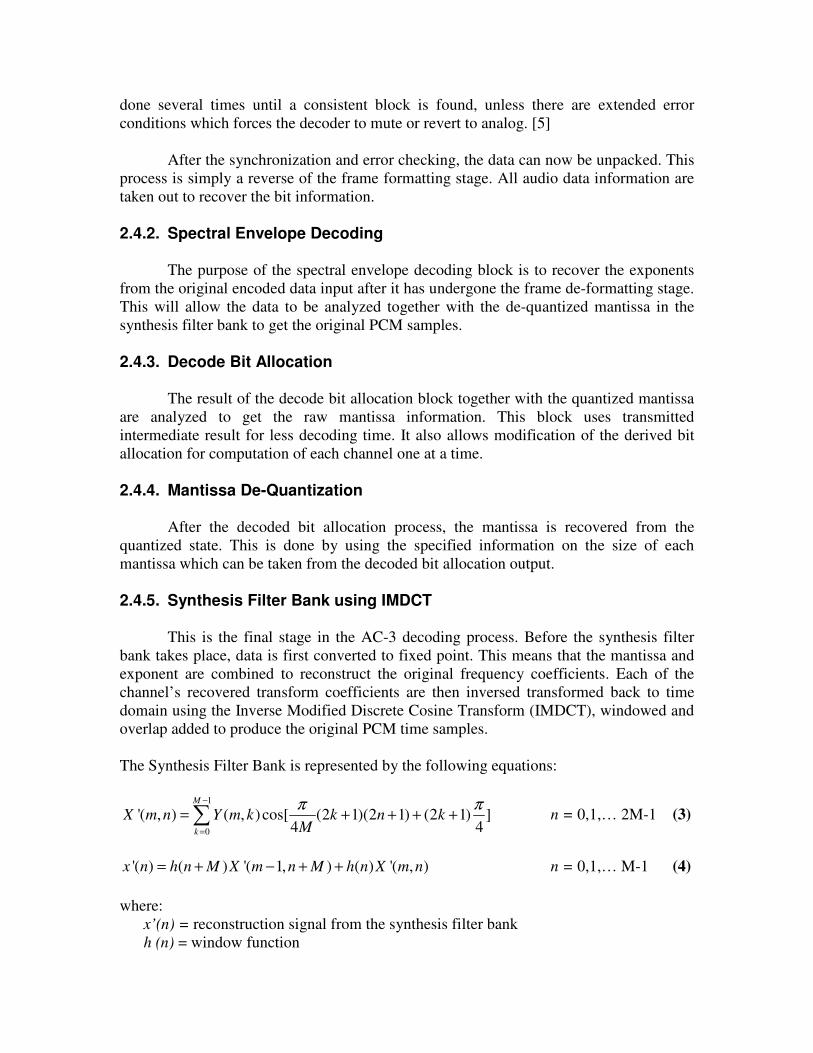
2.4.5. Synthesis Filter Bank using IMDCT
This is the final stage in the AC-3 decoding process. Before the synthesis filter
bank takes place, data is first converted to fixed point. This means that the mantissa and
exponent are combined to reconstruct the original frequency coefficients. Each of the
channel’s recovered transform coefficients are then inversed transformed back to time
domain using the Inverse Modified Discrete Cosine Transform (IMDCT), windowed and
overlap added to produce the original PCM time samples.
The Synthesis Filter Bank is represented by the following equations:
1
0
'( , ) ( , ) cos[ (2 1)(2 1) (2 1) ]4 4
M
k
X m n Y m k k n kM
π π−
=
= + + + +∑ n = 0,1,… 2M-1 (3)
'( ) ( ) '( 1, ) ( ) '( , )x n h n M X m n M h n X m n= + − + + n = 0,1,… M-1 (4)
where:
x’(n) = reconstruction signal from the synthesis filter bank
h (n) = window function
2.5 Related Works This project intends to implement the AC-3 audio coding standard by reviewing related
studies on filters and fast algorithms for efficient implementation. Comparison of filter
bank designs will be the main focus of this project.
2.6.3. The ATSC Standard: Digital Audio Compression (AC-3), Revision A
For technical guidelines on AC-3 encoding and specifications, the ATSC
Standard: Digital Audio Compression Revision A will be used. The AC-3 bit stream is
specified mainly by the syntax and decoder processing, thus the encoder is not precisely
defined. The only normative requirement on the encoding algorithm is that it is able to
produce a bit stream that follows the AC-3 syntax. ATSC documentation will be checked
for consistency of the encoder implementation.
2.6.4. FFmpeg Multimedia System
For the source code reference, the AC-3 encoder included in the codec library of the
FFmpeg project will be used. FFmpeg Multimedia System is a complete solution to
record, convert and stream audio and video. It is a trademark of Fabrice Bellard,
originator of the FFmpeg project and is an experimental and developer-driven project.
However, there are no formal releases yet.
The project is made of several components:
• ffmpeg – command line that converts video format to another
• ffserver – http multimedia streaming server for live broadcasts
• ffplay – simple media player
• libavformat – library containing parsers and generators for all common
audio/video formats
• libavcodec – the leading audio/video codec library that contains all
encoders/decoders. Most of codecs were developed from scratch to ensure quality
performances and high code reusability.
It is developed under Linux but it can be compiled under most operating system including
Windows.

Chapter 3
Methodology
The overview of the project is shown in Figure 3-1. For the first part, a reference
code was used which was modified to create a standard encoding algorithm. Different
designs were then implemented to come up with modified encoding algorithms. Finally,
quality performance of these encoder designs were then compared and analyzed using
different objective and perceptual tests to arrive at an optimum code which will be
selected among all of the implementations.
3.1 Design The AC-3 encoder consists of the following information:
• AC3_encode_init – sets the correct parameters for the AC-3 encoder
• AC3_encode_close – outputs the correct AC-3 bit stream
• AC3_encode_frame – contains the actual AC-3 encoding processing
The main encoding process takes place in the AC3_encode_frame. It contains several sub
functions that perform the different encoder processing requirements which can be
summarized in Figure 3-2. These include:
• mdct512 – calculates the MDCT of the 512 input time samples
• compute_exp_strategy– along with its sub blocks, this computes the exponent
strategy that will be used by the encoder
• compute_bit_allocation – along with its sub blocks, calculate the number of
bits needed by the encoder using mantissa information
• output_frame_header, output_frame_end, output_audio_block – frame
packing and bit stream formatting

Figure 3-1 AC-3 Encode Frame
Since the project deals with comparing different filter bank designs, it is
necessary that the other parts of the encoder will not be modified so as not to affect its
performance. Therefore, the different designs directly refer to the filter bank
implementations. As mentioned previously, the AC-3 filter bank uses an oddly-stacked
TDAC. The general equation that characterizes TDAC is shown below:
( ) ( )( )
( )( )
0
0
cos ( ) 1 cos2 2
sin ( ) 1 sin2 2
( )
( )
cos( ) sin( )2 2
k k
n
k
n
k
m mKX m x n h P n w n n
m mKx n h P n w n n
where K blocksize
x n time domain sequence
X m frequency data of band k in time block m
m mand swit
π
π
π π
∞
=−∞
∞
=−∞
= − + − +
+ − + − +
=
=
=
=
∑
∑
( )( ) ( )( )0 0
0
cos sin
( ) & ( )
k k
ches deciding which path according to block number
w n n and w n n analysis and synthesis filters
n phase delay
h n f n windows with size P
+ + =
=
=
By setting wk = (2 ( 1/ 2) )k Kπ + , replacing –r=mK/2-n and performing deductions, we
can rewrite the equation as a general form of MDCT.
exponent_min
output_frame_header
encode_exp
compute_exp_strategy
compute_bit_allocation
mdct512
output_frame_end
output_audio_block
calc_exp_diff
bit_alloc_masking
bit_alloc
compute_mantissa_size
AC3_encode_frame

The analysis filter bank is the processing of 512-time sample from time to
frequency domain where the current 256 input time samples are concatenated with the
256 time-sample of the previous set. The filter bank is completed in two major processes:
windowing and MDCT implementation.
The PCM samples are windowed through a normalization procedure by using a
Kaiser-Bessel window with 50% overlap between adjacent blocks. The Kaiser-Bessel
window can be described as:
0
0
[ , ]
[ ] , 02
[ , ]
n
p
KBD Left n
p
w pN
W n n
w p
α
α
=
−
=
= ≤ <∑
∑
[ ]
2/ 4
1.0/ 4
N where [ , ] , 0 n
2
o
o
n NI
Nw p
I
πα
απα
− −
= ≤ ≤
2
0
and( / 2)
[ ]!
k
o
k
xI x
k
∞
=
=
∑
For AC-3, α =4. The window characteristic described above is shown graphically
in Figure 3-2. The figure represents the transform window sequence whose values are
specified by the ATSC standard shown in Table 3-1.
Figure 3-2 AC-3 Window Sequence
Due to the window specification, the design modification now depends on the
type of MDCT implementation. This can be classified as (1) Direct (2) Indirect (3)
Recursive. Direct method, or traditional method, is the straightforward execution of the
MDCT block. The indirect method refers to the use of fast algorithms such as Fast
Fourier Transforms (FFT). The third method simply refers to algorithms that are
recursive in nature.

Table 3-1 AC-3 Transform Window Sequence (w[10A+B])
3.1.1 Direct Method
Given the time domain signal samples in a signal block ( ) x n where n=0 to N-1
windowed by an N sample real Kaiser-Bessel derived window w(n) to obtain x(n) , the
complete MDCT of x(n) is:
1
0
2 2( ) ( ) cos[ (2 1)(2 1) (2 1)(1 )] k=0,1,2,...(N/2)-1
4 4
1 for the first short transform
0 for the long transform
1 for the second short transform
N
D
n
X k x n n k kN N
π πα
α
−
=
= − + + + + +
−
= +
∑
Removing the scale factor and setting α =0 simplifies the MDCT to:
1
0
(2 1 / 2)(2 1)( ) ( )cos k=0,1,2,...(N/2)-1
2
N
n
n N kX k x n
N
π−
=
+ + +=∑
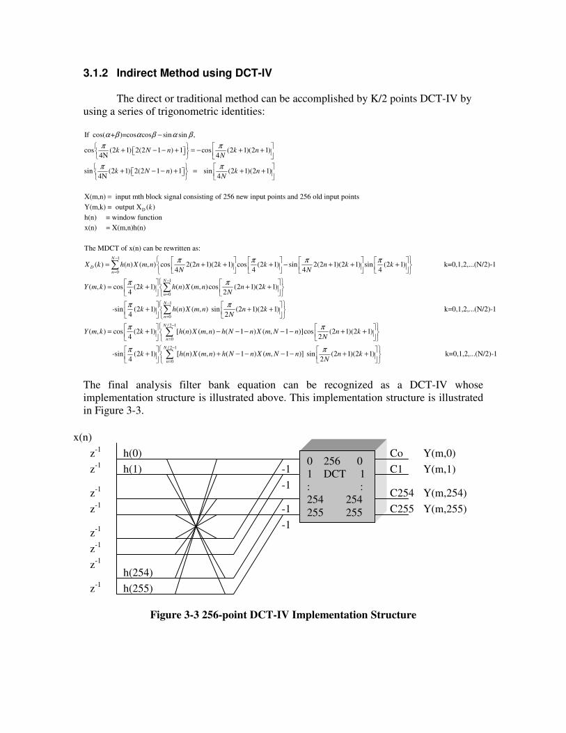
3.1.2 Indirect Method using DCT-IV
The direct or traditional method can be accomplished by K/2 points DCT-IV by
using a series of trigonometric identities:
If cos( + )=cos cos sin sin ,
cos (2 1) 2(2 1 ) 1 cos (2 1)(2 1)4N 4
sin (2 1) 2(2 1 ) 1 sin (2 1)(2 1)4N 4
X(m,n) input mth block signal consisting of 256
k N n k nN
k N n k nN
α β α β α β
π π
π π
−
+ − − + = − + +
+ − − + = + +
=
D
new input points and 256 old input points
Y(m,k) = output X ( )
h(n) = window function
x(n) = X(m,n)h(n)
The MDCT of x(n) can be rewritten as:
( ) ( ) ( , ) cos 2(2 1)(2 1) cos (2 1)4 4
D
k
X k h n X m n n k kN
π π
= + + +1
0
1
0
sin 2(2 1)(2 1) sin (2 1) k=0,1,2,...(N/2)-14 4
( , ) cos (2 1) ( ) ( , )cos (2 1)(2 1)4 2
-sin (2 1)4
N
n
N
n
n k kN
Y m k k h n X m n n kN
k
π π
π π
π
−
=
−
=
− + + +
= + + +
+
∑
∑1
0
/ 2 1
0
( ) ( , ) sin (2 1)(2 1) k=0,1,2,...(N/2)-12
( , ) cos (2 1) [ ( ) ( , ) (4
N
n
N
n
h n X m n n kN
Y m k k h n X m n h N
π
π
−
=
−
=
+ +
= + −
∑
∑/ 2 1
0
1 ) ( , 1 )]cos (2 1)(2 1)2
-sin (2 1) [ ( ) ( , ) ( 1 ) ( , 1 )] sin (2 1)(2 1) k=0,1,2,...(N/2)4 2
N
n
n X m N n n kN
k h n X m n h N n X m N n n kN
π
π π−
=
− − − − + +
+ + − − − − + +∑ -1
The final analysis filter bank equation can be recognized as a DCT-IV whose
implementation structure is illustrated above. This implementation structure is illustrated
in Figure 3-3.
Figure 3-3 256-point DCT-IV Implementation Structure
0 256 0
1 DCT 1
: :
254 254
255 255
z-1
z-1
z-1
z-1
z-1
h(0)
z-1
z-1
z-1
h(1)
h(254)
h(255)
-1
-1
-1
-1
Co Y(m,0)
C1 Y(m,1)
C254 Y(m,254)
C255 Y(m,255)
x(n)
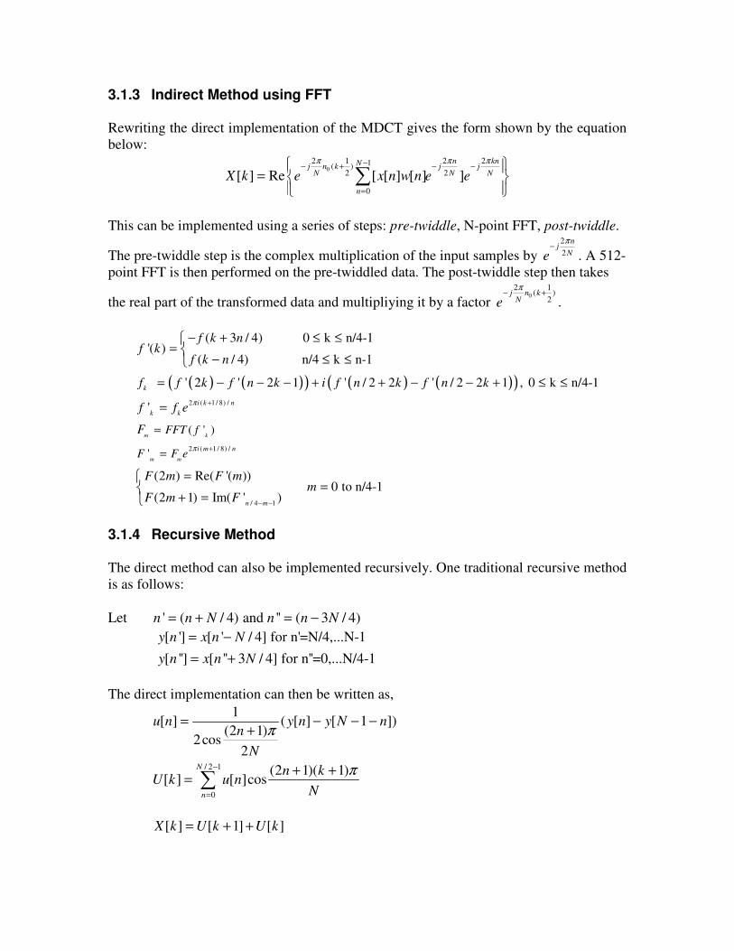
3.1.3 Indirect Method using FFT Rewriting the direct implementation of the MDCT gives the form shown by the equation
below:
0
2 1 2 21( )2 2
0
[ ] Re [ [ ] [ ] ]
n knNj n k j jN N N
n
X k e x n w n e e
π π π−− + − −
=
=
∑
This can be implemented using a series of steps: pre-twiddle, N-point FFT, post-twiddle.
The pre-twiddle step is the complex multiplication of the input samples by
2
2
nj
Ne
π−
. A 512-
point FFT is then performed on the pre-twiddled data. The post-twiddle step then takes
the real part of the transformed data and multipliying it by a factor 0
2 1( )
2j n k
Ne
π− +
.
( ) ( )( ) ( ) ( )( )2 ( 1 / 8) /
2 ( 1 / 8) /
( ' )
'
( 3 / 4) 0 k n/4-1'( )
( / 4) n/4 k n-1
' 2 ' 2 1 ' / 2 2 ' / 2 2 1 , 0 k n/4-1
'
(2 ) Re( '( ))
(2 1) Im( '
m k
m m
k
i k n
k k
i m n
n
FFT f
F F e
f k nf k
f k n
f f k f n k i f n k f n k
f f e
F
F m F m
F m F
π
π
+
+
=
=
− + ≤ ≤=
− ≤ ≤
= − − − + + − − + ≤ ≤
=
=
+ =
/ 4 1
0 to n/4-1)
m
m− −
=
3.1.4 Recursive Method The direct method can also be implemented recursively. One traditional recursive method
is as follows:
Let ' ( / 4) and '' ( 3 / 4)n n N n n N= + = −
[ '] [ ' / 4] for n'=N/4,...N-1
[ ''] [ '' 3 / 4] for n''=0,...N/4-1
y n x n N
y n x n N
= −
= +
The direct implementation can then be written as,
/ 2 1
0
1[ ] ( [ ] [ 1 ])
(2 1)2cos
2
(2 1)( 1)[ ] [ ]cos
N
n
u n y n y N nn
N
n kU k u n
N
π
π−
=
= − − −+
+ += ∑
[ ] [ 1] [ ]X k U k U k= + +

This previous equations also represents the DCT-IV. By applying trigonometric
identities, we get
/ 4 / 4 1 / 4 2
/ 4 / 4 1 / 4 2
[ ] [ ] ( 1) [ / 2 1 ]
[ ] cos ( [ ] [ 1]) 2cos [ ] [ ]2
[ ] sin ( [ ] [ 1]) 2cos [ ] [ ]2
k
k
N k k k N N
k
N k k k N N
p n u n u N n
D k p j p j D k D k
S k p j p j S k S k
θθ
θθ
− −
− −
= + − − −
= − − + −
= − − + −
Finally, the output X[n] can be derived by using these equations:
/ 2
/ 4 1 / 4 1
( 1) / 2
/ 4 1 / 4 1
[ ] ( 1) ( [ ] [ 1])for k is even
[ ] ( 1) ( [ 1] [ ])for k is odd
k
n n
k
n n
X k D k S k
X k D k S k
− −
−
− −
= − + +
= − + +
Clenshaw’s Recurrence Formula
The proposed algorithms based on a traditional recursive implementation can be
formally obtained using Clenshaw’s recurrence formula which is an elegant and efficient
way of evaluating the sum of the coefficients.. The formula states that the sum of a given
function f(x) can be obtained using this equation:
1 1 2 2 1 3( ) ( ) ( 1, ) ( ) ( )N n N N N N
f x c F x N x F x y F x yβ− − − − − −= − − −
Applying it for the MDCT implementation, let 1
2k k
M
πθ
= +
and define
2 1
1 2
0
( ) 2cosn k N N
a a
a x n a aθ− −
− −
= =
= + −
( ) ( ) ( )1 2 2 1 3( ) ( 1) N k N k N N k NX k x N F F a F aθ θ θ− − − − −= − + −
Appplying mathematical transformation to the direct method finally gives the output X(k)
as:
1 2( ) cos ( 1) cos ( 1)2 2
k k
N NX k M a M a
θ θ− −
= − − + +
The implementation structures of the traditional recursive transform and the recursive
solution using Clenshaw’s recurrence formula are shown in Figures 3-4(a) and 3-4(b)
respectively.

(a)
(b)
Figure 3-4 (a) Implementation structure for (a) traditional recursive method (b)
recursive based on Clenshaw’s recurrence formula
3.2 Implementation
FFmpeg Multimedia System was the main reference used for implementing the
designs using the C programming language. The code modification was done in an IDE
environment using Microsoft Visual Studio 2005.
However, the reference can only be compiled in Windows using selected software
that can complete the actual compiling and producing of the win32 binaries. Thus, the
compilation was done in a command line Linux environment using the MingGW and
Minimal SYStem (MSys) system with an integrated gcc compiler. MSys is a branch of
Cygwin used in Windows OS for creating configuration and packages. It also offers user
environment for MinGW development and allows users of MinGW version of GCC to
port and build packages in a GNU familiar way without the UNIX complexities brought
about by Cygwin.
The implementation procedure involves a direct application of the different
methods for the MDCT processing block.

3.3 Testing
There were initial tests done to evaluate the performance of the designs. A
preliminary listening test was already implemented to determine the test samples to be
used for the objective test. A formal listening test will be done during the last phase of the
project.
Figure 3-5 Flowchart of the Testing Procedure
3.3.1 Preliminary Test
The main objective of the preliminary test was to determine the type of audio
samples that are best suited for the objective tests. Different types of audio vary in
frequency contents. Thus to produce rational results for the objective analysis, worst case
scenario must be considered. This scenario implies that the encoded audio sample should
be far from the original PCM audio. If the difference between the quality of the encoded
audio sample and the original audio is almost unnoticeable, we can immediately expect
that the results will be almost identical.
The International Telecommunication Union [ITU-R BS.1284] provides the
appropriate guidelines and scale to be used for quality assessment. In determining the
relative difference of two samples with quality far from each other, the seven-grade
comparison scale shown in the figure below is recommended.
Grade Comparison
3 Much Better
2 Better
1 Slightly Better
0 The Same
-1 Slightly Worse
-2 Worse
-3 Much Worse
The system used was the Multiple Stimulus with Hidden Reference and Anchors
(MUSHRA) method. It is a double blind multiple stimulus test method with hidden
Preliminary
Test
Objective Tests Formal
Listening Test
Traditional
and Modified Designs
Listening and
Objective Test Results
reference. This setup involves a reference audio that can be compared against multiple
test samples, wherein one of the test samples is the actual same copy of the reference
sample unknown to the listener. Ideally, the user must be able to give a grade of zero
since one of the test samples is its duplicate.
For this project, the reference audio used was the original PCM audio. One of the
test samples was a copy of the original and the rest of the test samples were the different
designs used for implementing the AC-3 encoding algorithm.
The preliminary listening test was then performed using three different PCM
audio (plain speech, a pop music, and an instrumental song) using randomly selected AC-
3 encoder designs (direct method, MDCT using DCT-IV and MDCT using FFT).
In addition to this, preliminary objective test was done to assess the frequency
response of the selected audio.
3.3.2 Objective Tests
After getting the results of the preliminary listening test, the audio sample was
selected and the objective tests were performed using MATLAB 7.0. However, since
MATLAB is unable to directly read AC-3 formats, the encoded audio sounds were first
recorded to raw PCM format that MATLAB recognizes.
The software used was Audacity, an open source program capable of recording
sounds without the need for microphone and speaker set-up. This ensures that there is no
degradation in audio quality and the characteristics of the encoded audio format can truly
be analyzed.
Moreover, stereo separation into left and right channels was done in order to study
the correlation and frequency response of the encoded AC-3 audio. The autocorrelation
of the original PCM audio was plotted against the correlation between the original audio
and each design. This will illustrate whether or not the encoded AC-3 audio and the
original PCM are highly correlated.
The frequency response of each design was then determined to verify if there are
noticeable differences compared to that of the original PCM audio. The flowchart below
summarizes the procedure done for the objective tests.

Figure 3-6 Flowchart of the Objective Test Procedure
3.3.3 Formal Listening Test
Formal listening test is considered the ultimate measurement of audio quality. The
test was done in a similar manner to that in the preliminary listening tests.
However, the scale used for the formal listening test is the five-grade impairment
scale. This is defined by the [ITU-R BS.562-3] as the scale used for systems with small
impairments. This is related to the five-grade quality scale as shown below. The test
method used is still a double blind multiple stimulus test method with hidden reference.
Grade ITU-R Grade
5 Imperceptible
4 Perceptible, but annoying
3 Slightly annoying
2 Annoying
1 Very annoying
3.3.4 Playback
The open source encoder AC3Filter developed by Alexander Vigovsky on August
2006 [9] will serve as the AC-3 main decoder. AC3Filter is a high quality free
DirectShow AC-3 filter that allows decoding of videos with AC3-encoded surround
audio.
The source is composed of the filter and an audio processing library. The filter
implements all interfaces and logic required by DirectShow while the audio processing
Objective Analysis
- frequency response and correlation
Objective Test Results
Channel Separation
- to left and right channels in MATLAB
AC-3 recording
- to PDCM audio using Audacity
Traditional and Modified Designs
library implements all audio decoding and processing algorithms. It supports
configuration settings that allow control of audio sound intensity and can decode AC-
3/DTS/MPEG1/2 Audio Layer I/II formats. Some of the features include decomposition
to six channels, full information about the audio track format, per channel amplification
for all input/output channels and per channel delays.
3.3.5 Listening Conditions
The listening tests were performed with the listeners having direct control on the
listening conditions. The direct control includes being allowed to repeat the audio
samples and change the audio volume level for. They were asked to use headphones
throughout the duration of testing.
Chapter 4
Results and Analysis 4.1 Objective Measurements
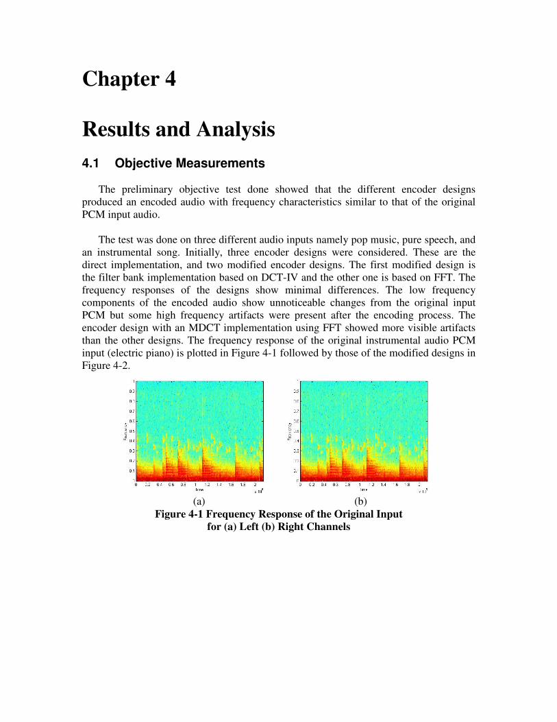
The preliminary objective test done showed that the different encoder designs
produced an encoded audio with frequency characteristics similar to that of the original
PCM input audio.
The test was done on three different audio inputs namely pop music, pure speech, and
an instrumental song. Initially, three encoder designs were considered. These are the
direct implementation, and two modified encoder designs. The first modified design is
the filter bank implementation based on DCT-IV and the other one is based on FFT. The
frequency responses of the designs show minimal differences. The low frequency
components of the encoded audio show unnoticeable changes from the original input
PCM but some high frequency artifacts were present after the encoding process. The
encoder design with an MDCT implementation using FFT showed more visible artifacts
than the other designs. The frequency response of the original instrumental audio PCM
input (electric piano) is plotted in Figure 4-1 followed by those of the modified designs in
Figure 4-2.
(a) (b)
Figure 4-1 Frequency Response of the Original Input
for (a) Left (b) Right Channels

(c) (d)
(e) (f)
(g) (h)
Figure 4-2 Frequency Response of the Different Designs using:
(c) - (d) Direct Method , (e) –(f) Indirect Method DCT-IV ,
(g) - (h) Indirect Method FFT for both left and right channels
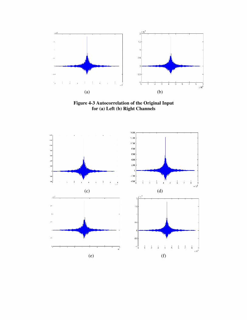
The crosscorrelation of the original input PCM and the encoded audio for each design
was also determined and is illustrated in Figure 4-3.
(a) (b)
Figure 4-3 Autocorrelation of the Original Input
for (a) Left (b) Right Channels
(c) (d)
(e) (f)

(g) (h)
Figure 4-4 Correlation of the Different Designs and Original Input PCM
using: (c) - (d) Direct Method , (e) –(f) Indirect Method DCT-IV ,
(g) - (h) Indirect Method FFT for both left and right channels
The results above show that there is a high correlation between the encoded audio and
the original input PCM. Though frequency response and correlation present a general
insight on the frequency components present in an audio sample and its correlation with
the original input, it shows little or no information on the quality of the encoded audio
aside from the noticeable appearance of frequency artifacts.
4.2 Audio Test Samples
The preliminary listening test done reveal that the listener was not be able to
recognize the impairments among the different designs immediately for ordinary pop
music, but it became more obvious when the input audio sample used contains high
frequency components, and thus, high pitch. This is in line with the result of the
frequency response mentioned earlier when frequency artifacts appear after encoding.
It is also more noticeable when the audio sample is made up of a single instrument or
speech. The ensemble of musical instruments masks the impairments brought about by
the encoder design. Table 4-1 shows the average grade given by 10 listeners.
Test Sample Encoder Design Arithmetic Mean
Pop Music Original -0.3333
Direct 0
Indirect using DCT 0.6667
Indirect using FFT 1.125
Speech Original 0.3333
Direct -1
Indirect using DCT -1.1111
Indirect using FFT -1.5556
Table 4-1 Result for the preliminary listening tests

Having realized this, the selections of critical material used are listed in Table 4-2.
The test samples are composed primarily of different musical instruments expect for
speech and pop music.
Input Test Samples
1. CLARINET
2. DRUMSET
3. GUITAR_CONCERT
4. GUITAR_ELECTRIC
5. PIANO_CONCERT
6. PIANO_ELECTRIC
7. POP MUSIC
8. SAXOPHONE
9. SPEECH
Table 4-2 List of critical materials to be used
Chapter 5
Project Schedule
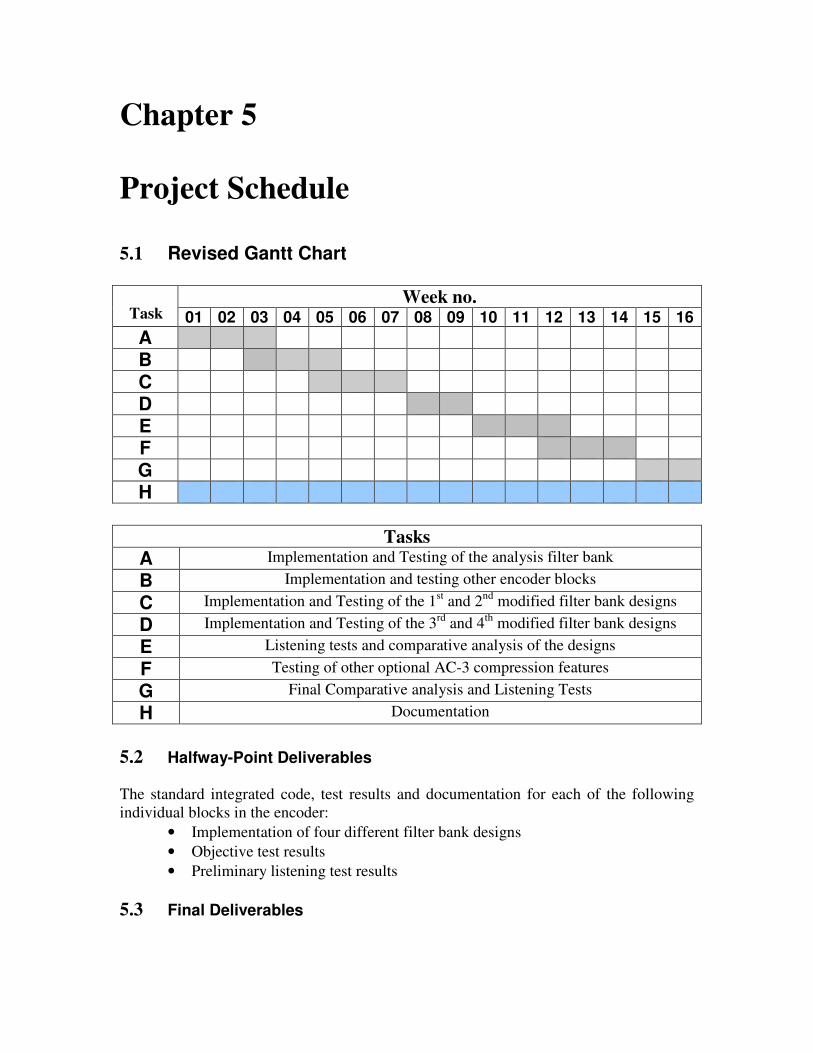
5.1 Revised Gantt Chart
Week no. 01 02 03 04 05 06 07 08 09 10 11 12 13 14 15 16
A B C D E F G H
Tasks
A Implementation and Testing of the analysis filter bank
B Implementation and testing other encoder blocks
C Implementation and Testing of the 1st and 2
nd modified filter bank designs
D Implementation and Testing of the 3rd
and 4th
modified filter bank designs
E Listening tests and comparative analysis of the designs
F Testing of other optional AC-3 compression features
G Final Comparative analysis and Listening Tests
H Documentation
5.2 Halfway-Point Deliverables The standard integrated code, test results and documentation for each of the following
individual blocks in the encoder:
• Implementation of four different filter bank designs
• Objective test results
• Preliminary listening test results
5.3 Final Deliverables
Task

The final deliverables include four filter bank designs and analysis of AC-3 audio
compression feature. The comparative analysis of four different filter bank
implementations before the conclusion of the optimum final code will also be presented,
stating grounds for selecting the design. All functional and listening test results will also
be presented along with the full documentation of the project implementation.

Bibliography [1] C. Liu and W. Chang. “Audio Coding Standards”. National Chiao Tung
University, Taiwan.
[2] Digital Audio Formats. http://www.teamcombooks.com/mp3handbook/12.htm
Feb 10, 2007
[3] Dolby AC-3 Audio Coding. http://www.fedele.com/website/hdtv/dolbyac3.htm
Feb 10, 2007
[4] Dolby AC-3. http://www.mp3-tech.org.htm. Feb 10, 2007
[5] M. Davis. “The AC-3 Multichannel Coder”. Dolby Laboratories Inc., San
Francisco, 1993.
[6] C. Todd, G. Davidson, M. Davis, L. Fielder, B. Link, and S. Vernon. “AC-3:
Flexible Perceptual Coding for Audio Transmission and Storage”. Dolby
Laboratories Inc., San Francisco, 1994.
[7] A. Alvarez, S. George, H. Yang, and K. Das. “SGS-Thomson DSP D950-Core
Audio Compression”. DSP R&D Centre SGS-Thomson Microelectronics”.
[8] Y. Chen, C. Tsai, and J. Wu. “Fast Time-Frequency Transform Algorithms and
their Applications to Real-Time Software Implementation of AC-3 Audio Codec”.
National Taiwan University.
[9] AC3Filter Project. http://ac3filter.net/ Feb 10, 2007
[10] AC3Decode. http://www.users.on.net/%7Ersobon/ac3dec.html Feb 10, 2007
[11] Z. Zhao. “Efficient Implementation Structures of AC-3’s Filter Banks.” Hangzhou
Institute of Electronic Engineering, Hangzhou China.
[12] S. Lee and C. Liu. “Transformation from 512-point transform coefficients to 256-
point transform coefficients for Dolby AC-3 decoder”