ABSTRACT I. INTRODUCTION - UGC Approved Journal · Developing a Programme for ... Presently Airbus...
12
International OPEN ACCESS Journal Of Modern Engineering Research (IJMER) | IJMER | ISSN: 2249–6645 | www.ijmer.com | Vol. 5 | Iss.1| Jan. 2015 | 48| Developing a Programme for Engine Design Calculations of a Commercial Airliner K. Suresh 1 , K. Sai Sharath 2 , Karrothu Vigneshwara 3 , V.Rajiv 4 1 Asst. Professor, 2,3,4 Student, Aeronautical dept., Guru Nanak Eng. College(GNITC), Hyderabad, India I. INTRODUCTION As we all know that an engine is the heart of any vehicle, without the engine there wouldn’t be a vehicle. This heart in an aircraft is really big and there may be not one but four hearts. Designing these engines is really tricky and involves some serious work. Well it would basically require any engine designer to fill up this design sheet(fig 1.1).It is really a tedious work and requires a lot of time. This project basically allows any aeronautical engineering student to get acquainted with the theory behind designing of an aircraft engine and so as to save time with calculation a program for calculating has been developed. ABSTRACT: This project leads to a path of understanding the necessary fundamental calculations that need to be done during an engine design of a commercial airliner. These calculations are hand based calculations that are done based on the parameters of the airframe data provided by the airline manufacturers. These calculations are a little tedious and require a paper and a pen to carry out the procedures. This project will enable the following outcomes for the students: providing a fundamental understanding of the aircraft engine design, more from the grounds up approach and an automated way (program) of doing the above, enabling faster iterations and making it easy to achieve the required parameters for designing an engine. Keywords: Bypass ratio,Efficiency, Flow properties, HTML, PHP, Turbofan engine.
Transcript of ABSTRACT I. INTRODUCTION - UGC Approved Journal · Developing a Programme for ... Presently Airbus...

International
OPEN ACCESS Journal Of Modern Engineering Research (IJMER)
| IJMER | ISSN: 2249–6645 | www.ijmer.com | Vol. 5 | Iss.1| Jan. 2015 | 48|
Developing a Programme for Engine Design Calculations of a
Commercial Airliner
K. Suresh1, K. Sai Sharath
2, Karrothu Vigneshwara
3, V.Rajiv
4
1Asst. Professor, 2,3,4Student, Aeronautical dept., Guru Nanak Eng. College(GNITC), Hyderabad, India
I. INTRODUCTION As we all know that an engine is the heart of any vehicle, without the engine there wouldn’t be a
vehicle. This heart in an aircraft is really big and there may be not one but four hearts. Designing these engines
is really tricky and involves some serious work. Well it would basically require any engine designer to fill up
this design sheet(fig 1.1).It is really a tedious work and requires a lot of time. This project basically allows any
aeronautical engineering student to get acquainted with the theory behind designing of an aircraft engine and so
as to save time with calculation a program for calculating has been developed.
ABSTRACT: This project leads to a path of understanding the necessary fundamental calculations that
need to be done during an engine design of a commercial airliner. These calculations are hand based
calculations that are done based on the parameters of the airframe data provided by the airline
manufacturers. These calculations are a little tedious and require a paper and a pen to carry out the
procedures. This project will enable the following outcomes for the students: providing a fundamental
understanding of the aircraft engine design, more from the grounds up approach and an automated way
(program) of doing the above, enabling faster iterations and making it easy to achieve the required
parameters for designing an engine.
Keywords: Bypass ratio,Efficiency, Flow properties, HTML, PHP, Turbofan engine.

Developing a Programme for Engine Design Calculations of A Commercial Airliner
| IJMER | ISSN: 2249–6645 | www.ijmer.com | Vol. 5 | Iss.1| Jan. 2015 | 49|
II. LITERATURE SURVEY The Boeing 747-400 was the largest civil aircraft that was introduced in service in the year 1989 but it
is a derivative of the 747-100 which entered service in 1969. Presently Airbus A380 is the largest civil aircraft
in this world. The 747-400 incorporated some aerodynamic improvements, including some improvements to the
existing engines, but a much more radical redesign is needed to take the full advantage of the developments in
aerodynamics and materials since 1969. Boeing and Airbus industries have separately and jointly discussed
proposals for a much larger plane, with anywhere from about 600 to about 800 seats.
Boeing at that time had announced plans for a major derivative of the 747 to incorporate new wings
and to be propelled by new engines. Two versions were proposed, the 747-500 and 747-600, with a common
wing. The 747-600, which it is proposed should be produced first, was intended to carry 548 passengers over a
range of up to 7890nm, whilst the 747-500 was to carry 462 passengers over a range of up to 8830nm. Airbus
then proposed the A3XX with an expected capacity of 555 passengers for a range of up to 7450nm. It takes several years to design, develop and certificate a new plane, though the length of time is
becoming shorter. It seems to take even longer to develop the engines, but until the specifications of the plane
are settled it is not clear what engine is needed. There are currently three major engine manufactures and they
are, Rolls Royce in Britain, Pratt & Whitney and General Electrics in the USA and it is their aim to have an
engine already for whatever new large aircraft is decided to build.
A specifications for the ‘paper’ airplanes alter, the ‘paper’ engine design to power them will also
change; literally hundreds of potential engines will be tried to meet a large number of proposals for the new
airplane before any company finally commits itself.
It is essential to realize that both the new plane, and the engines which power it, will depend heavily on
the experience gained in earlier products. In Table 2.1 below, the proposed specifications for the New Large
Aeroplane are therefore set beside those achieved for the 747-700. Table 2.1 Comparison of some salient aircraft parameters
New Large Aeroplane NLA Boeing 747-400
No. of passengers 620 400
Range(nautical miles) 8000 7300
Payload at this range (a) 58.5tonne 38.5tonne
Max take-off weight (d = a + b + c) 635.6tonne 395.0tonne
Empty weight (b) 298.7tonne 185.7tonne
Fuel capacity (c) 275.4tonne 174.4tonne
Cruise Mach No. 0.85 0.85
Initial cruise Altitude 31000ft 31000ft
Cruise Lift/Drag 20 17.5
Wing Area 790m2 511m2
The atmosphere through which the plane flies depends on the altitude, with the pressure, temperature
and density failing as altitude increases. At high altitude the variations with season, location and time of day is
much less than at ground level and it is normal to use a standard atmosphere in considering aircraft and engine
performance. According to International Civil Aviation Organization the values at altitudes are expressed as a
ratio to the values at sea level. Standard sea-level atmospheric conditions are defined for a standard day: Tsl =
288.15K, Psl = 101.3 kPa, ρsl = 1.225 kg/m3. In Standard atmosphere temperature is assumed to decrease
linearly with altitude at 6.5K per 1000m below the tropopause, but to remain constant above this altitude at
216.65K. Cruise often begins at 31000ft, and the corridors are separated by 2000ft. below table (2.2) gives
information about different conditions of standard atmosphere.
Table 2.2 Useful values of ICAO standard atmosphere
ALTITUDE TEMPERATURE PRESSURE DENSITY
Feet Km K 105 Pa Kg/m3
0 0 288.15 1.013 1.225
31000 9.45 226.73 0.287 0.442
33000 10.05 222.28 0.260 0.336
35000 10.67 218.80 0.238 0.380
37000 11.28 216.65 0.214 0.285
39000 11.88 216.65 0.197 0.316
41000 12.50 216.65 0.179 0.287
51000 15.54 216.64 0.110 0.179

Developing a Programme for Engine Design Calculations of A Commercial Airliner
| IJMER | ISSN: 2249–6645 | www.ijmer.com | Vol. 5 | Iss.1| Jan. 2015 | 50|
The below fig (2.1) gives the ICAO standard atmosphere:
Fig 2.1: ICAO Standard Atmosphere
In order to calculate the speed of vehicle that is required for further calculation part is given by the formula;
Mach no =SPEED OF VECHILE
SPEED OF SOUND (1)
The speed of sound formula can be given by;
a=√ɣ RT (2)
Where: a = Speed of sound ɣ = 1.4
R = 287 J/kg K
T = Temperature at given altitude (i.e. Ta)
Hence in order to find out the speed of the vehicle;
V = M x a (3)
Where: V = speed of sound
M = Mach no
a = speed of sound
III. THEORY BEHINDTHE CALCULATION OF ESSENTIAL PARAMETERS There are three main critical legs of a flight that affect the engine performance, they are: Take-off,
Climb and Cruise. In any engine the first parameter to be fixed would be thrust. There has to be a compromise
between a machine that can travel fast at cruise and relatively slow during take-off and landing. The lift co-
efficient is given as;
CL = L / 1
2ρAV2 (4)
Where L is the lift force that acts perpendicular to the direction of travel.The figure below shows how the lift of
the aircraft varies with angle of attack at low speeds such as take-off and it can be seen that the lift rises almost
proportionally to the incidence until around the peak, beyond which it falls rapidly. The rapid fall in the lift is
referred to as stall and in simple terms occurs when the boundary layer separates from the upper surface of the wing.
Fig 3.1:A Typical curve of Lift vs Incidence

Developing a Programme for Engine Design Calculations of A Commercial Airliner
| IJMER | ISSN: 2249–6645 | www.ijmer.com | Vol. 5 | Iss.1| Jan. 2015 | 51|
It is an objective of a civil aircraft to lift as much as it can with the least possible drag. Reducing the
drag for the same lift allows the aircraft to use less fuel and to travel further. For steady level flight at small
incidence, as for cruise, two statements can be made on the basis of simple mechanics: Lift = Weight and Drag = Thrust of the engines
To estimate the range we use Breguet’s Range equation; dw
dt= −g(sfc × net thrust) = −g(sfc × drag) = −g
sfc ×w
l d (5)
Where L/D ratio of lift to drag and we use W=L. Rearranging
dw
w= −
g sfc dt
L/D (6)
This equation can then be rewritten in terms of distance travelled s as dw
w= −
g sfc ds
V L/D (7)
Keeping VL/D and sfc constant the above equation can be then integrated to give Breguet’s range
formula
s = −VL
D
g sfc × ln(
wend
wstart) (8)
A flow of fuel mf passes down the pylon, but its velocity is low and it conveys negligible momentum. A
mass flow of air mair enters the engine; mair is typically two orders of magnitude greater than mf. It is assumed for simplicity here that the jet is uniform as it crosses the control surface with velocity Vj. The thrust is
calculated by considering the flux of momentum across the control surface around the engine – since the
pressure is assumed uniform over the control surface the pressure creates no net force. Considering the flow
which crosses the control surface and passes through the engine, we can write down two fluxes are;
Flux of momentum entering the engine = mair x V. (9)
Flux of momentum leaving the engine = (mair+mf ) x Vj. (10)
The extra mass flow in the jet is included here for completeness, but this represents a small effect for high
bypass ratio engine.
The net thrust FN which is available in flight is given by the difference between the two momentum fluxes, that
is;
FN = (mair+mf ) x Vj - mair x V (11)
If the engine were being tested on a stationary test bed or before the aircraft started to move the thrust produced is known as the gross thrust, which, since V=0, is given by;
FG = (mair+mf ) x Vj. (12)
The difference between gross and net thrust is mairV, often referred to as the ram drag or the inlet-momentum
drag, so;
FN = FG - mair xVj. (13)
Here we have ignored the drag on the outside of the engine nacelle drag, which leads to a ring of reduced
relative velocity around the jet and consequent reduction in useful thrust. Unfortunately, nacelle drag is
becoming a more significant factor as the engine becomes larger for the same thrust, i.e. as the bypass ratios go
up. The Kinetic Energy of the engine can be given as;
∆𝐾𝐸 = 1
2[ 𝑚𝑎𝑖𝑟 + 𝑚𝑓 𝑉𝑗2 − 𝑚𝑎𝑖𝑟𝑉2] (14)
The power actually associated with propelling the aircraft is given by;
𝑃𝑜𝑤𝑒𝑟 𝑡𝑜 𝑡𝑒 𝑎𝑖𝑟𝑐𝑟𝑎𝑓𝑡 = 𝑓𝑙𝑖𝑔𝑡 𝑠𝑝𝑒𝑒𝑑 × 𝑛𝑒𝑡 𝑡𝑟𝑢𝑠𝑡 = 𝑉 × 𝐹𝑛
= V[(mair+mf ) x Vj - mair x V]. (15)
The propulsiveefficiency compares the power supplied to the aircraft with the rate of increase in kinetic energy
of the air through the engine. Propulsive efficiency Ƞ p is straightforward to define by;
Ƞ𝑝 = 𝑃𝑜𝑤𝑒𝑟 𝑡𝑜 𝑎𝑖𝑟𝑐𝑟𝑎 𝑓𝑡
𝑃𝑜𝑤𝑒𝑟 𝑡𝑜 𝑗𝑒𝑡 (16)
Ƞ𝑝 = V[(𝑚𝑎𝑖𝑟 +𝑚𝑓 ) x Vj − 𝑚𝑎𝑖𝑟 x V]
1
2[ 𝑚𝑎𝑖𝑟 +𝑚𝑓 𝑉𝑗 2−𝑚𝑎𝑖𝑟 𝑉2]
(17)
Since, as already noted, the mass flow rate of fuel is very much less than that of air it is possible to write Ƞ p
with sufficient accuracy for our present purposes as;

Developing a Programme for Engine Design Calculations of A Commercial Airliner
| IJMER | ISSN: 2249–6645 | www.ijmer.com | Vol. 5 | Iss.1| Jan. 2015 | 52|
Ƞp = 2𝑉
𝑉+𝑉𝑗 (18)
The above equation is known as the Froude equation for propulsive efficiency.
The overall efficiency is given by;
Ƞo = 𝑈𝑠𝑒𝑓𝑢𝑙 𝑤𝑜𝑟𝑘
𝑇𝑒𝑟𝑚𝑎𝑙 𝑒𝑛𝑒𝑟𝑔𝑦 𝑓𝑟𝑜𝑚 𝑓𝑢𝑒𝑙= Ƞp × Ƞth (19)
From the first law of thermodynamics when applied to this steady flow process can be written as;
𝑄𝑛𝑒𝑡 − 𝑊𝑛𝑒𝑡 = 𝑚𝑎𝑖𝑟 × ∆ (20)
Where ∆ is the enthalpy difference between the inlet air and the exhaust based on stagnation condition;
𝑄𝑛𝑒𝑡 − 𝑊𝑛𝑒𝑡 = 𝑚𝑎𝑖𝑟 × 𝐶𝑝 × (𝑇5 − 𝑇2) (21) This can be written in terms of lower calorific value of the fuel;
𝑚𝑓 × 𝑙𝑐𝑣 = 𝑚𝑎𝑖𝑟 × 𝐶𝑝 × (𝑇4 − 𝑇3) (22)
These isentropic processes are those which ideal compressors and turbines would perform. As can be seen, the
actual compression process involves a greater temperature rise than
That of the isentropic compressor for the same pressure rise;
T3 – T2> T3is – T2 (23)
And in the same way
T4 – T5< T4 – T5is (24)
For compressors and turbines it is normal to define efficiencies which relates actual work per unit mass flow to that of an ideal (i.e. loss free) machine with equivalent pressure change;
Ƞ𝑐𝑜𝑚𝑝 = 𝐼𝑑𝑒𝑎𝑙 𝑤𝑜𝑟𝑘
𝐴𝑐𝑡𝑢𝑎𝑙 𝑤𝑜𝑟𝑘 And Ƞ𝑡𝑢𝑟𝑏 =
𝐴𝑐𝑡𝑢𝑎𝑙 𝑤𝑜𝑟𝑘
𝐼𝑑𝑒𝑎𝑙 𝑤𝑜𝑟𝑘 (25)
Treating fluid as a perfect gas, for which h=cpT.
Ƞ𝑐𝑜𝑚𝑝 = T3is – T2
T3 – T2 𝑎𝑛𝑑 Ƞ𝑡𝑢𝑟𝑏 =
T4 – T5
T4 – T5is (26)
Nowadays the isentropic efficiencies in a high quality aircraft engine for use on a civil aircraft are likely to be
around 90% for compressor and turbine and this round number will normally be used in this project. 𝑝
𝑇𝛾
𝛾−1
= 𝑐𝑜𝑛𝑠𝑡𝑎𝑛𝑡 (27)
This means in the present cases, 𝑇3𝑖𝑠
𝑇2= (
𝑝3
𝑝𝑎)(𝛾−1)/𝛾 𝑎𝑛𝑑
𝑇4
𝑇5𝑖𝑠= (
𝑝4
𝑝𝑎)(𝛾−1)/𝛾 . (28)
The power which must be supplied to the compressor is given by;
𝑊𝑐 = 𝑚𝑎𝑖𝑟 × 𝐶𝑝 × (𝑇3 − 𝑇2) (29)
𝑊𝑡 = 𝑚𝑎𝑖𝑟 × 𝐶𝑝 × 𝑇4 − 𝑇5𝑖𝑠 (30)
The Thermal Efficiency of the cycle can be given as;
Ƞ𝑐𝑦𝑐𝑙𝑒 =𝑊𝑛𝑒𝑡
𝑚𝑎𝑖𝑟 ×𝐶𝑝× 𝑇4−𝑇3 (31)
But the thermal efficiency can be given by;
Ƞ𝑡 = 𝑊𝑛𝑒𝑡/𝑚𝑓 × 𝐿𝐶𝑉 (32)
Fig 3.3: The Comparison between Efficiency of cycle and that of Pressure Ratio.
Developing a Programme for Engine Design Calculations of A Commercial Airliner
| IJMER | ISSN: 2249–6645 | www.ijmer.com | Vol. 5 | Iss.1| Jan. 2015 | 53|
The blade cooling can be given by;
𝜀 = (𝑇𝑔 − 𝑇𝑚)/(𝑇𝑔 − 𝑇𝑐) (33)
Turbine inlet temperature is important because increasing its value makes the pressure ratio across the
core turbine smaller inrelation to the pressure rise of the core compressor and thereby increases the power
available from the LP turbine. Increasing this temperature also increases the thermal efficiency, provided that
the pressure ratio increases by an appropriate amount.
Table 3.1:Representing the Compressor and Turbine inlet temperatures
T2 T4 T4/T2
Take-Off (Standard day,
sea level)
288.15 K 1700 K 5.90
Top of Climb(31000ft,
M=0.85)
259.5 K 1575 K 6.07
Start Of Cruise(31000ft,
M=0.85)
259.5 K 1450 K 5.59
The steady flow energy equations for the flow of gas with no heat transfer and no external work transfer can be
written as;
1 +𝑉12
2= 2 + 𝑉22/2 (34)
Where h is the enthalpy, which can be rewritten in a way more convenient for us;
𝐶𝑝 × 𝑇 +𝑉2
2= 𝐶𝑝 × 𝑇𝑜 (35)
Where To is the stagnation temperature, being that temperature which the gas would attain if brought to rest
without work and heat transfer, not necessarily in an ideal or loss-free manner. The specific heat can be
rewritten as 𝐶𝑝 = 𝛾𝑅/(𝛾 − 1) and on rearranging and inserting this into the above equation the stagnation
temperature may be written as; 𝑇𝑜
𝑇= 1 + (𝛾 − 1)/2 × (
𝑉2
𝛾𝑅𝑇) (36)
Again this equation between stagnation temperature T0 and static temperature T does not imply ideal or loss-free
acceleration or deceleration.
At this point we suppose that the acceleration or deceleration of the gas between the static state p and T and that
at stagnation p0 and T0 is reversible and adiabatic, for which we know that; 𝑃
𝜌𝛾 = 𝑐𝑜𝑛𝑠𝑡𝑎𝑛𝑡 𝑎𝑛𝑑𝑝
𝑇𝛾
𝛾−1
= 𝑐𝑜𝑛𝑠𝑡𝑎𝑛𝑡 (37)
It then immediately follows that; 𝑝0
𝑝= (
𝑇0
𝑇)𝛾/(𝛾−1) (38)
The bypass ratio is defined as the mass flow of the air passing outside the core divided by the mass flow through
the core;
𝑏𝑝𝑟 = 𝑚𝑏/𝑚𝑐 (39)
The choice of bypass ratio has a major effect on the efficiency, because for a given core the bypass ratio
determines the jet velocity. The bypass ratio also greatly affects the appearance, size and weight of the engine:
the pure turbojet has a small diameter relative to its length, whereas high bypass ratio engines have their overall
diameter comparable to their length.Previous engines (the RB211, CF6 and JT9D generation) had bypass ratios
of around 5 and we may assume that a bypass ratio at least as great as this will be employed in a new engine for
the New Large Aircraft.
To achieve this it would probably be necessary to install a gear box between the LP turbine and the fan, to allow
the turbine to run faster; this requires considerable development and will very probably be heavy. For a civil
transport engine a major requirement is low fuel consumption, equivalent to high overall efficiency. The overall efficiency is the product of propulsive and thermal efficiency;
Ƞ0 = Ƞ𝑝 × Ƞ𝑡 (40)
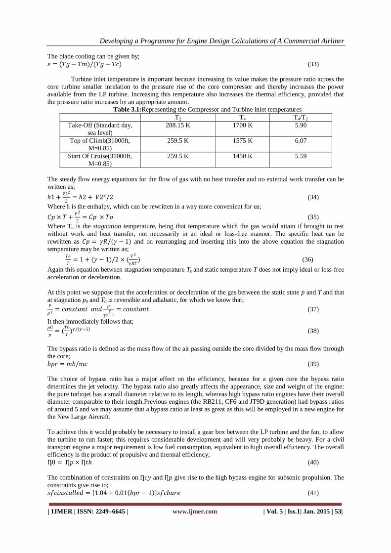
The combination of constraints on Ƞ𝑐𝑦 and Ƞ𝑝 give rise to the high bypass engine for subsonic propulsion. The
constraints give rise to;
𝑠𝑓𝑐𝑖𝑛𝑠𝑡𝑎𝑙𝑙𝑒𝑑 = 1.04 + 0.01 𝑏𝑝𝑟 − 1 𝑠𝑓𝑐𝑏𝑎𝑟𝑒 (41)
Developing a Programme for Engine Design Calculations of A Commercial Airliner
| IJMER | ISSN: 2249–6645 | www.ijmer.com | Vol. 5 | Iss.1| Jan. 2015 | 54|
Fig 3.4: Prediction variation of sfc with bypass ratio for bare and installed engine
IV. PROBLEMS WITH SOLUTION To find the engine thrust needed for steady flight at start of cruise, when the weight of the aircraft and
wing area for the NLA at altitude 31000ft and Mach number of 0.85. Given;
Initial Cruise altitude: 31000ft Cruise Mach number: 0.85 Ambient Temperature= 226.7K Ambient pressure= 28.7x10
3 Pa Speed of sound at cruise altitude a= 301.827 m/s
Cruise speed of the aircraft V= 256.5 m/s Aircraft mass at start of cruise = 635.6x10³ Kg
Aircraft L/D ratio= 20
And thus;
L/D = 20
Lift/Drag = 20
Replacing Lift with Weight and Drag with Thrust,
Weight/Thrust = 20
W/T =20
635.6 × 1000 × 9.81 𝑇 = 20 𝑇 = 635.6 × 1000 × 9.81 20
𝑇 = 311.655 kN Thrust per engine (Assuming the large aircraft to have 4 engines) = 77.914 kN/engine
Calculating the thermal efficiency and the net work per kg of air flowing in the engine. Assume
isentropic efficiencies of compressor and turbine is 90%. For the following conditions;
T2 = 259.5K, T4 = 1450K, PR = 40.
Given:T2 = 259.5K T4 = 1450K PR = 40
𝑇3𝑖𝑠 = 𝑃𝑅𝛾−1
𝛾 × 𝑇2 (41)
T3is = 716.63K on substitution of values in the above equation
.: The work done by the compressor is,
𝑊𝑐 = 𝐶𝑝 × (𝑇3𝑖𝑠 − 𝑇2)/Ƞ𝑐𝑜𝑚𝑝
Wc = 510.47 Kj/kg
𝑇5𝑖𝑠 = 𝑇4/(𝑃𝑅𝛾−1
𝛾 ) (42)
T5is = 525.05K on substituting the values in the above equation
.:
The work done by the turbine is;
𝑊𝑡 = 𝐶𝑝 × (𝑇4 − 𝑇5𝑖𝑠) × Ƞ𝑡𝑢𝑟𝑏 (43)
Wt = 836.61 Kj/kg .:
𝑊𝑛𝑒𝑡 = 𝑊𝑡 − 𝑊𝑐 = 326.14 𝑘𝐽/𝑘𝑔
Ƞ𝑡 =𝑊𝑛𝑒𝑡
𝐶𝑝× 𝑇4 − 𝑇3 = 0.4754
Finding Temperature entering the core compressor and hence the temperature at exit from the core
compressor and the temperature leave the H.P turbine and the pressure at the outlet from the turbine. The
temperature and pressure at cruise is 259.5K and 46.0 KPa. Assume a pressure ratio of 1.6 for flow through the
fan which enters the core and a pressure ratio of 25 in the core compressor itself. The temperature of the entry of
H.P turbine is 1450K. Assume efficiency of compressor and turbine 90%.

Developing a Programme for Engine Design Calculations of A Commercial Airliner
| IJMER | ISSN: 2249–6645 | www.ijmer.com | Vol. 5 | Iss.1| Jan. 2015 | 55|
𝑇𝑓𝑎𝑛
𝑇𝑎𝑖𝑟= 𝑃𝑟(𝛾−1)/𝛾 = 1.143
𝑇𝑓𝑎𝑛 = 296.79𝐾 𝑇𝑓𝑎𝑛𝑖𝑠 − 𝑇 𝑎𝑖𝑟 × 100 = 𝑇𝑓𝑎𝑛 − 𝑇𝑎𝑖𝑟 × 90
𝑇𝑓𝑎𝑛 = 300.9𝐾
∆𝑇 = 41.4𝐾
Now to find the Core temperatures: 𝑇𝑒𝑥𝑡𝑐𝑜𝑟𝑒𝑖𝑠
𝑇𝑒𝑛𝑡𝑐𝑜𝑟𝑒= 𝑃𝑟2(𝛾−1)/𝛾
𝑇𝑒𝑥𝑐𝑜𝑟𝑒𝑖𝑠 = 754.80𝐾 𝑇𝑒𝑥𝑐𝑜𝑟𝑒𝑖𝑠 − 𝑇𝑒𝑛𝑐𝑜𝑟𝑒 × 100 = (𝑇𝑒𝑥𝑐𝑜𝑟𝑒 − 𝑇𝑒𝑛𝑐𝑜𝑟𝑒) × 90
𝑇𝑒𝑥𝑐𝑜𝑟𝑒 = 805.2𝐾
∆𝑇𝑐𝑜𝑟𝑒𝑐𝑜𝑚𝑝𝑒𝑟𝑠𝑠𝑜𝑟 = ∆𝑇𝑡𝑢𝑟𝑏𝑖𝑛𝑒
𝑇𝑒𝑥𝑡𝑢𝑟𝑏 = 945.6𝐾 𝑇𝑒𝑛𝑡𝑢𝑟𝑏− 𝑇𝑒𝑥𝑡𝑢𝑟𝑏 × 100 = (𝑇𝑒𝑛𝑡𝑢𝑟𝑏− 𝑇𝑒𝑥𝑡𝑢𝑟𝑏𝑖𝑠) × 90
𝑇𝑒𝑥𝑡𝑢𝑟𝑏𝑖𝑠 = 889.66𝐾
𝑃𝑓𝑎𝑛 = 1.6 × 46 = 73.6 𝑃𝑐𝑜𝑚𝑝 = 73.6 × 25 = 1840
𝑇5𝑖𝑠
𝑇4
𝛾/(𝛾−1)
=𝑃
1840 = 332.82 𝑘𝑃𝑎
If the airplane cruises at Mach number of 0.85 at an altitude of 31000ft find the stagnation temperature and pressure of the flow perceived by the plane.
We know that; 𝑇0
𝑇= 1 +
𝛾−1
2× 𝑀2 = 1.1445 (44)
𝑇0 = 1.1445 × 226.73 = 259.5𝐾
𝑝0
𝑝𝑎=
𝑇0
𝑇
𝛾
𝛾−1
= 1.603
𝑝0 = 1.603 × 28.7 = 46.0 𝑘𝑃𝑎 Using the results above to provide the inlet conditions into the LP turbine at a flight Mach number of
0.85 at 31000 ft. Assume equal velocity for the core and bypass jets. Assume thatthe inlet decelerates the flow
isentropically and the nozzles expand the flow isentropically to ambient pressure. Take the isentropic
efficiencies for the fan and for the LP turbine to be each 0.90. The following is calculated: The jet velocity, propulsive efficiency, gross thrust FG and net thrust FN and the Overall Efficiency.
For bpr = 10
We know that 𝑏𝑝𝑟 + 1 × ∆𝑇𝑓𝑎𝑛 = ∆𝑇𝑙𝑝𝑡𝑢𝑟𝑏
7 × ∆𝑇𝑓𝑎𝑛 = ∆𝑇𝑙𝑝𝑡𝑢𝑟𝑏 = 376.2𝐾
.:
𝑇05 = 945.7 − 376.2 = 569.5𝐾
𝑇05𝑖𝑠 = 945.7 −∆𝑇𝑙𝑝𝑡𝑢𝑟𝑏
0.90= 527.7𝐾
Temp ratio = 7.705
𝑃05 = 43.2 𝑘𝑃𝐴
𝑃𝑎 = 28.7 𝑘𝑃𝐴 Pressure ratio = 0.889
𝑉𝑗2 = 2 × 1004.5 × 569.5 × (1 − 0.889)
𝑉𝑗 = 355.3 𝑚/𝑠
𝐹𝐺 =𝑉𝑗
𝑚𝑎𝑖𝑟 + 𝑚𝑓 = 3.91 𝑘𝑁 𝑘𝑔−1𝑠
Ƞ𝑝 =2𝑉
𝑉 + 𝑉𝑗= 0.839
Ƞ0 = 0.428 𝐹𝑁 = 1.087 𝑘𝑁 𝑘𝑔−1𝑠 𝑠𝑓𝑐 = 0.492𝑘𝑔
/𝑘𝑔

Developing a Programme for Engine Design Calculations of A Commercial Airliner
| IJMER | ISSN: 2249–6645 | www.ijmer.com | Vol. 5 | Iss.1| Jan. 2015 | 56|
From the above results the following graphs are obtained:
Fig 4.1: Prediction variations in Thrust and SFC with bypass ratio for constant core
V. RESULTS AND CONCLUSION From the above we can say that the parameters are interdependent on each other and one must be careful
in calculating the parameters involved in designing an engine for a new large aircraft. As one can see that there
is a lot of work involved when one sits to design an engine, in order to simply the above process we developed a
program using HTML and PHP 5 programing language. The result program looks like this:
Fig 5.1: The main page of the program with all the input variables
Developing a Programme for Engine Design Calculations of A Commercial Airliner
| IJMER | ISSN: 2249–6645 | www.ijmer.com | Vol. 5 | Iss.1| Jan. 2015 | 57|
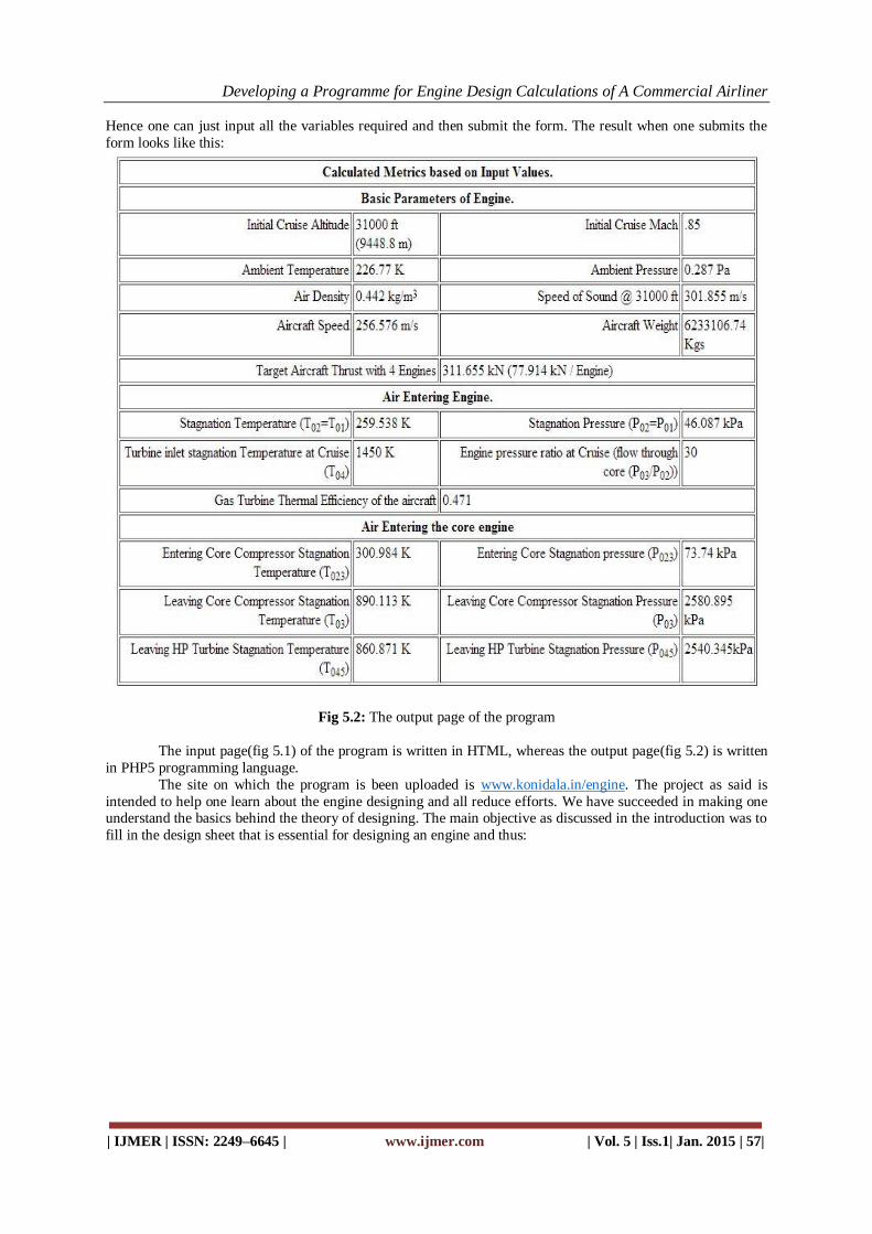
Hence one can just input all the variables required and then submit the form. The result when one submits the
form looks like this:
Fig 5.2: The output page of the program
The input page(fig 5.1) of the program is written in HTML, whereas the output page(fig 5.2) is written
in PHP5 programming language.
The site on which the program is been uploaded is www.konidala.in/engine. The project as said is
intended to help one learn about the engine designing and all reduce efforts. We have succeeded in making one understand the basics behind the theory of designing. The main objective as discussed in the introduction was to
fill in the design sheet that is essential for designing an engine and thus:

Developing a Programme for Engine Design Calculations of A Commercial Airliner
| IJMER | ISSN: 2249–6645 | www.ijmer.com | Vol. 5 | Iss.1| Jan. 2015 | 58|
Fig 5.3: Design sheet
Fig 5.4: The completed design sheet.

Developing a Programme for Engine Design Calculations of A Commercial Airliner
| IJMER | ISSN: 2249–6645 | www.ijmer.com | Vol. 5 | Iss.1| Jan. 2015 | 59|
REFERENCES [1]. THE JET PROPULSION’ by NICHOLAS CRAIG
[2]. ANDERSON J D. ‘Introduction to Flight’. McGraw-Hill Book Co. Inc. 3rd Edition, 1989. [3]. BAHR D W & DODDS W J. ‘Design of Modern Turbine Combustors’ Academic Press Inc., San Deigo C.A., 1990. [4]. COHEN H, ROGERS G F C & SARAVANAMUTTOO H I H. ‘Gas Turbine Theory’ 5th Edition, 2001. [5]. CUMPSTY N A. ‘Compressor Aerodynamics’ Longman, 1989. [6]. DIXON S L. ‘Fluid Mechanics, Thermodynamics of Turbomachinery’. Butterworth-Heinemann, 3rd Edition, 1995. [7]. GREEN J E. ‘Greener by Design - the technology challenge’, The Aeronautical Journal, Vol. 106, pp57-113, 2002. [8]. GUNSTON B. ‘The Development of Jet and Turbine Aero Engines’, Patrick Stephens Ltd., Spark ford, England, 2nd
Edition, 1997. [9]. HÜNECKE K. ‘Jet Engines: Fundamentals of Theory, Design and Operation’, England, 1997.
[10]. HILL P G & PETERSON C R. ‘Mechanics and Thermodynamics of Propulsion’. Addison-Wesley, Second Edition, 1992.
[11] INTERGOVERNMENTAL PANEL ON CLIMATE CHANGE’. Aviation and the Global Atmoshpere,Special Report of IPCC Working Groups I& III. 1999 (Cambridge University Press).
[12]. ISO Standard Atmosphere ISO 2533 International Standards Organization, Geneva 1975. [13]. ‘THE JET ENGINE’. Rolls Royce, 4th Edition, 1986.
[14]. KERREBROCK J L. ‘Aircraft Engines’.