Airbus A380 - General · Airbus A380 - General Wheels/Brakes Max. ... FLS allows to fly published...
33
Airbus A380 - General Wheels/Brakes Max. T for Takeoff 300°C Max GS 204 kt NWS Angle Rudder 6…2/0° (x-over 100…150 kt) NWS Angle Handwheels 70…0° (x-over 40…100 kt) V LE /V LO 250 kt/M 0.55 V LE /V LO gravity extension 220 kt/M0.48 Max. allowed Wing Fuel Imbalance Feed Tanks 1/4 or 2/3 3000 kg Inner Tanks 3000 kg Mid Tanks 2500 kg Outer Tanks 1200 kg APU Max Start Alt. (M < 0.56) 20000’ Max Alt. for Bleed/Elec 22500’ Max Start EGT (Ground) 700°C Max Start EGT (Flight) 800°C Dimensions Wingspan 79.75 m/261’8” Stabilizer Span 30.372 m/99’8” Wheel Span 14.336 m/47’4” ENG 2-3 29.598 m/97’1” ENG 1-4 51.4 m/168’8” Length 72.727 m/238’7” Tail Height 24.093 m/79’1” Eye Height 7.2 m/23.6’ NLG-Eye Dist 2.1 m/6.89’ NLG-Nose Dist 4.97 m/16.31’ Windshield Cutoff 19.23° Cutoff Distance 20.61 m/67.63’ Weights & Limitations Max Taxi Wt 571 t MTOW 569 t MLW 391 t MZFW 366 t Minimum Wt 270 t Max Range 8300 nm V MO /M MO 340 kt/M 0.89 (trans FL300) Max Alt. 43100’ Engines (RR Trent 900) - Environmental Envelope Takeoff & Landing (PA) between -42…35°C min -2000’ max 10000’ down to -54°C max. 6000’ up to 55°C max. 0’ Engines (RR Trent 900) - Thrust Settings/EGT Limits Operating Condition Time Limit EGT Limit T/O & G/A AEO 5’ 900°C OEI 10’ MCT no limit 850°C Starting on ground 700°C in flight 850°C Engines (RR Trent 900) - Oil Limits Max. Continuous Temp. 196°C Minimum Starting Temp. -40°C Min. Temp. prior Takeoff 40°C Quantity before Start 6 qt or more + est. consumption (0.66 qt/h), total min. 10 qt (OAT 0°C or more) or 13 qt (OAT < 0°C) Minimum Pressure 25 PSI + 25…50 PSI at 70… 95% N3 Flap Placard Speeds 1 263 kt 1+F 222 kt 2 220 kt 3 196 kt FULL 182 kt V MCL 120 kt (AEO) V MCL 144 kt (TEI) Cockpit Window Max opening speed 250 kt Max closing speed 160 kt Windshield wipers 250 kt Pressurization Max diff press (pos) 9.2 PSI Max diff press (neg) -0.725 PSI Use of Autopilot Flight Phase Minimum Height Takeoff 100’ AGL, at least 5 s after liftoff NPA 200’ AGL Circling 200’ AGL ILS, CAT 1 on FMA 160’ AGL after manual G/A 100’ AGL all other phases 500’ AGL
Transcript of Airbus A380 - General · Airbus A380 - General Wheels/Brakes Max. ... FLS allows to fly published...

Airbus A380 - General
Wheels/Brakes
Max. T for Takeoff 300°C
Max GS 204 kt
NWS Angle Rudder 6…2/0° (x-over 100…150 kt)
NWS Angle Handwheels 70…0° (x-over 40…100 kt)
VLE/VLO 250 kt/M 0.55
VLE/VLO gravity extension 220 kt/M0.48
Max. allowed Wing Fuel Imbalance
Feed Tanks 1/4 or 2/3 3000 kg
Inner Tanks 3000 kg
Mid Tanks 2500 kg
Outer Tanks 1200 kg
APU
Max Start Alt. (M < 0.56) 20000’
Max Alt. for Bleed/Elec 22500’
Max Start EGT (Ground) 700°C
Max Start EGT (Flight) 800°C
Dimensions
Wingspan 79.75 m/261’8”
Stabilizer Span 30.372 m/99’8”
Wheel Span 14.336 m/47’4”
ENG 2-3 29.598 m/97’1”
ENG 1-4 51.4 m/168’8”
Length 72.727 m/238’7”
Tail Height 24.093 m/79’1”
Eye Height 7.2 m/23.6’
NLG-Eye Dist 2.1 m/6.89’
NLG-Nose Dist 4.97 m/16.31’
Windshield Cutoff 19.23°
Cutoff Distance 20.61 m/67.63’
Weights & Limitations
Max Taxi Wt 571 t
MTOW 569 t
MLW 391 t
MZFW 366 t
Minimum Wt 270 t
Max Range 8300 nm
VMO/MMO 340 kt/M 0.89 (trans FL300)
Max Alt. 43100’
Engines (RR Trent 900) - Environmental Envelope
Takeoff & Landing (PA) between -42…35°C
min -2000’
max 10000’
down to -54°C max. 6000’
up to 55°C max. 0’
Engines (RR Trent 900) - Thrust Settings/EGT Limits
Operating Condition Time Limit EGT Limit
T/O & G/AAEO 5’ 900°C
OEI 10’
MCT no limit 850°C
Startingon ground 700°C
in flight 850°C
Engines (RR Trent 900) - Oil Limits
Max. Continuous Temp. 196°C
Minimum Starting Temp. -40°C
Min. Temp. prior Takeoff 40°C
Quantity before Start
6 qt or more + est. consumption (0.66 qt/h), total min. 10 qt (OAT 0°C or more) or 13 qt (OAT < 0°C)
Minimum Pressure 25 PSI + 25…50 PSI at 70…95% N3
Flap Placard Speeds
1 263 kt
1+F 222 kt
2 220 kt
3 196 kt
FULL 182 kt
VMCL 120 kt (AEO)
VMCL 144 kt (TEI)
Cockpit Window
Max opening speed 250 kt
Max closing speed 160 kt
Windshield wipers 250 kt
Pressurization
Max diff press (pos) 9.2 PSI
Max diff press (neg) -0.725 PSI
Use of Autopilot
Flight Phase Minimum Height
Takeoff 100’ AGL, at least 5 s after liftoff
NPA 200’ AGL
Circling 200’ AGL
ILS, CAT 1 on FMA 160’ AGL
after manual G/A 100’ AGL
all other phases 500’ AGL

Airbus A380 - ECAM
WARNINGS & CAUTIONS
Priority Aural Alert/Attention Getter Description Crew Action
Level 3 WARNING CRC/specific sound/voice, MASTER WARN emergency situation immediate
Level 2 CAUTION SC, MASTER CAUT abnormal situation not immediate, awareness
Level 1 CAUTION none e.g. redundancy loss none, awareness
WARNINGS & CAUTIONS
Cautions Warnings
INDEPENDENT HYD G SYS OVHT
INDEPENDENT ELEC EMER CONF
PRIMARY HYD G SYS PRESS LOW (boxed)
SECONDARY * FCTL
Procedures & Checklists
ECAM detection Preceding Character Item Status Color (Procedure) Color (Checklist)
YES dashnot completed blue blue
completed white green
NO squarenot validated blue blue
validated white green
ECAM Colors
RED Warning immediate crew action
AMBERCaution
not completed deferred procedures not immediate crew action
GREEN normal indications completed C/L items
MAGENTA specific memos
WHITE
completed deferred procedures conditional lines
titles & sub-menus procedure action line complete
BLUEactions to be done
limitations to be followed checklist items to be checked
GRAY completed checklists actions not yet validated

Airbus A380 - AFS AFS Architecture: 3 primary flight control and guidance computers (PRIM) and 2 flight management systems (FMS1/FMS2), of which each is operated by one of three flight management computers (FMC-A, FMC-B or FMC-C).
PRIMs control flight guidance (FG: AP, FD, A/THR), flight envelope (FE) and flight controls. The one with the best operational capability is master, the other slaves. With same capacity, order is 1…3. Slaves are on standby. Transfer of master/slave according to operational capability is automatic.
FMC-A provides data to FMS1 (captain’s side), FMC-B to FMS2 (FO’s side), FMC-C is on standby. AP1 means FMC-A is master, FMC-B master on AP2. FMC-C regularly updated by master FMC. In case of FMC failure, standby FMC synchronizes with active FMC that is still healthy and replaces faulty FMC. FMS1/2 are still operative. If two FMCs fail, use FMS switching. If all FMCs fail, tune NAV aids via RMP & create basic F-PLN via ISIS.
Interface with AFS via AFC CP or software backup on MFDs, MFDs, KCCUs, FMA, NDs, EFIS CPs, AP disconnect pb, thrust levers, A/THR disconnect pushbuttons. MFD is interface for FCU backup, SURV and ATC.
*in selected lateral guidance (e.g. HDG), OP CLB is engaged.
FMA Modes
TAXICLB NAV 1FD2
entering LOC beamCLB RWY NAV 1FD2
thrust levers set to TOGA or MCT/FLEX
MAN FLX +55
SRS CLB
RWY NAV 1FD2
A/THR
if F-PLN inserted 30’ RA
MAN FLX +55
SRS CLB
NAV1FD2 A/THR
if NAV not armed/engaged 50’ RA
MAN FLX +55
SRS OP CLB
RWY TRK1FD2 A/THR
thrust reduction altitude (LVR CLB flashing)
MAN FLX +55 LVR CLB
SRS CLB
NAV1FD2 A/THR
thrust levers moved to CL detent
AP2 engaged
THR CLB SRS CLB
NAV AP2 1FD2 A/THR
acceleration altitude if NAV engaged and AFS CP
altitude above current alt*
THR CLB CLB ALT
NAV AP2 1FD2 A/THR
if altitude constraint must be maintained before AFS CP
selected altitude
THR CLB CLB ALT
NAV AP2 1FD2 A/THR
capturing constraint altitude SPEED ALT CST* CLB
NAV AP2 1FD2 A/THR
maintaining constraint altitude SPEED ALT CST CLB
NAV AP2 1FD2 A/THR

FMA Modes (cont’d)
climbing towards cruise altitude
THR CLB CLB ALT CRZ
NAV AP2 1FD2 A/THR
reaching cruise altitude MACH ALT CRZ* NAV AP2 1FD2 A/THR
maintaining cruise altitude MACH ALT CRZ NAV AP2 1FD2 A/THR
selecting lower altitude and pulling ALT knob of AFS CP
(constraints are ignored)
THR IDLE OP DES ALT
NAV AP2 1FD2 A/THR
selecting lower altitude and pulling ALT knob of AFS CP (constraints are respected)
THR IDLE DES ALT
NAV AP2 1FD2 A/THR
selecting lower altitude and selecting V/S on AFS CP (constraints are ignored)
MACH V/S -3000 ALT
NAV AP2 1FD2 A/THR
APPR pb pressed and ILS/RA not faulty, A/C above 400’, ILS FRQ/CRS identical on RCVRs
SPEED ALT G/S
HDG LOC
CAT3 DUAL
BARO 570
AP1+2 1FD2 A/THR
capturing LOC SPEED ALT G/S
LOC* CAT3 DUAL
BARO 570
AP1+2 1FD2 A/THR
LOC captured SPEED ALT G/S
LOC CAT3 DUAL
BARO 570
AP1+2 1FD2 A/THR
capturing G/S LOC* or LOC must be
engaged
SPEED G/S* LOC CAT3 DUAL
BARO 570
AP1+2 1FD2 A/THR
400’ RA FCU selections are no longer
taken into account!
SPEED LAND CAT3 DUAL
BARO 570
AP1+2 1FD2 A/THR
60’ RA SPEED FLARE CAT3 DUAL
BARO 570
AP1+2 1FD2 A/THR
thrust levers set to TOGA flaps lever not at 0
FMS predictions lost
MAN TOGA
SRS OP CLB
GA TRK AP1+2 1FD2 A/THR
engaging NAV or HDG SRS remains
MAN TOGA
SRS OP CLB
NAV AP1+2 1FD2 A/THR
G/A acceleration altitude FMS predictions recovered
CLB engages
MAN TOGA
LVR CLB
CLB ALT CRZ
NAV AP1+2 1FD2 A/THR
levers in CL detent THR CLB CLB ALT CRZ
NAV AP1+2 1FD2 A/THR

FLS allows to fly published NPA and LOC type approach (LOC, LOC B/C, …) in a way similar to precision approaches. FLS available when published NPA coded in FMS database, at least one FMS and one MMR available, approach capability F-APP or F-APP+RAW. Offset between final approach course and runway course must not exceed 50°.
AP, FD and A/THR are integrated within the FG. Modes appear on the flight mode annunciator (FMA) of PFDs. FG uses AP/FD lateral modes for lateral trajectory, AP/FD vertical modes for vertical trajectory and/or speed/Mach and A/THR modes to control thrust or speed/Mach. Some lateral and vertical modes are linked to common modes, e.g. LAND.
The two FDs can be displayed on both PFDs. There is only one button to switch them off and on. FD1 is linked to ADIRS1 and FMS1, FD2 to ADIRS2 and FMS2. To engage both FDs, the following must be available: 1 PRIM, 2 ADRs, 2 Its, AFS CP or AFS CP backup page, normal law (alternate law in some cases). FDs automatically engage at power up. FD roll bar is replaced by yaw bar below 30’ during landing/takeoff when localizer available. FDs automatically engage with GA.
AP off and FDs switched off: lateral/vertical modes disengage. A/THR engaged in THR mode reverts to SPEED/MACH. AP on and FDs switched off: lateral/vertical modes remain engaged.
FD bars disappear when pitch <-13° or >25° or bank >45°, reappear when pitch/bank again within limits. FD bars disappear in ROLL OUT mode if difference between a/c track and runway track >20°.
FDs disengage when A/THR not engaged and a/c speed below VLS or above VMAX, if a condition required for FD engagement is no longer met or if both FD fail. Dual ADR failure leads to loss of both APs and both FDs.
Pitch and/or roll bar flash for 10 s on both PFD in case of mode reversion or permanently on respective PFD if failure occurs in one of the equipment used for approach.
Short term managed speed (magenta dot): - selected mode: short term managed speed represents speed that will be commanded upon switch to managed - managed mode: magenta triangle shows long term target not taking into account a/c configuration, see table
Auto TCAS: RA is flown by autopilot. AP is not engaged in manual flight, but FD and A/THR automatically activate.
FLS Capability
Minimum System Availability
Displayed FLS Capability
F-APP F-APP+RAW RAW ONLY
FMC 1 1 1
Navigation accuracy GPS PRIMARY within one FMS
High accuracy within one FMS
no requirement
FLS function (within MMR) 1 1 1
GPS receiver 1 0 0
ADIRS 2 1 1
All NPA can be flown, NAV aids overlay required by some authorities!
NAV aids are required to cross check with raw data, no RNAV or GPS APP!
Approach based on display of raw data, FLS function can not be used!
Short term managed speed
Managed speed target Short term managed speed
Above VMAX VMAX - 5 kt
Below maneuvering speed: Green Dot, S, F Green Dot, S, F
Below VLS VLS

Airbus A380 - Network System In addition to ARINC 429, A380 uses avionics full duplex switched ethernet (AFDX). It improves information exchange between equipment. When new equipment is added, no new cable is necessary, only an update of the AFDX switch configuration table. Avionics data communication network (ADCN) connected to "Open World" commercial services, ethernet/internet for PAX, maintenance system, ground link) via secure communication interface (SCI, firewall).
ADCN is composed of two independent, identical and redundant AFDX networks (each a set of 8 interconnected switches). A switch can simultaneously receive and transmit data to the appropriate output ports. Conventional and new avionics are linked to the AFDX switches of both networks, directly or via input/output modules (IOM). New avionics on A380 are CPIOM (core processing input/output modules) directly connected to AFDX networks and IOM, gateways between conventional avionics and AFDX networks. CPIOMs combine several functions in one module. 22 CPIOMs are split into 7 types: Bleed Air, Air Conditioning, Cockpit, Communication, Electrical, Fuel, Landing Gear. No ECAM alert related to specific CPIOM failure, only for aircraft systems monitored and controlled by failed CPIOM.
IOMs manage transfer to/from AFDX networks of different types of inputs/outputs and are grouped in pairs for redundancy.
No crew control for ADCN: system fully automatic once powered. No AFDX switch reset capability from cockpit. Better redundancy thanks to two AFDX networks, IOMs in pairs and each system connected to both AFDX networks.
IOM & switch failures
Single IOM failure in one pair no operational effect
single IOM failure in two pairs no operational effect, AVIONICS NETWORK DOUBLE IOM FAULT
multiple IOM failure (only one per pair) no operational effect, AVIONICS NETWORK MULTIPLE IOM FAULT (REDUNDANCY DEGRADED) for info
failure of both IOMs of at least one pair communication between connected a/c systems and both avionics networks lost, AVIONICS NETWORK MULTIPLE IOM FAULT (REDUNDANCY DEGRADED) with actions
failure of single switch no operational effect, regardless of network (A or B)
failure of two switches in one network no operational effect, AVIONICS NETWORK DOUBLE SWITCH FAULT
failure of three or more AFDX switches affecting only one redundant network
no operational effect, AVIONICS NETWORK MULTIPLE SWITCH FAULT (REDUNDANCY DEGRADED) for info
failure of two or more AFDX switches affecting both networks
communications affected, AVIONICS NETWORK MULTIPLE SWITCH FAULT (REDUNDANCY DEGRADED) with actions

Airbus A380 - Electrical System Electrical system consists of normal network (115 VAC and 28 VDC) and emergency network. AC generated by:
1. four engine driven generators (GEN 1, GEN 2, GEN 3, and GEN 4), 2. two APU generators (APU GEN A, APU GEN B) and 3. up to four external power units (EXT 1, EXT 2, EXT 3 and EXT 4).
When running, each engine drives a generator, which provides AC power at variable frequency to its assigned bus. If a generator fails, buses can be supplied by other generators. At least two engine generators are necessary to supply all buses. In normal ops, AC 1 supplies AC ESS bus, which can also be supplied by AC 4 in case of failure or manual switching of AC ESS FEED pb. AC ESS supplies AC EMER bus.
APU is second AC source. When running, APU drives two generators at the same time, providing power at constant frequency of 400 Hz. Any APU generator can replace any engine generator. The two APU generators can supply the entire a/c network on ground. Only one APU generator can operate in flight.
External power units are third AC source. Up to four EPUs can be connected, providing AC power at constant frequency of 400 Hz. At least two EPUs are required to supply the entire a/c network (preferably EXT 2 and EXT 3).
Each generator and external power unit is controlled and monitored by its assigned generator and ground power control unit (GGPCU). The same GGPCU is used for one engine generator and one external power (GGPCU 1…4 for GEN 1…4 and EXT 1…4 respectively, GGPCU 5 & 6 for APU GEN A & B).
Supply of AC bus power in order of priority: 1. assigned engine generator 2. assigned external power unit (on ground 3. APU generator on same side 4. APU generator on other side 5. other generator on same side 6. other external power unit on same side 7. symmetrical engine generator on opposite side 8. symmetrical external power unit on opposite side
DC is delivered by transformer rectifiers (TRs) and by the batteries. A/C has four batteries (BAT 1, ESS BAT, BAT 2 and APU BAT), which cannot be disconnected from their dedicated hot bus. Four TRs transform AC power to DC power and control connection and disconnection of assigned batteries to prevent power interruption during source transfer. The DC network is thus a no break power transfer (NBPT) network (only applies to DC, so most avionics and all DUs).
TR 1 transforms AC 2 power to DC 1 bus and controls connection and disconnection of associated BAT 1 to DC 1 bus. ESS TR transforms AC ESS bus to DC ESS, controls connection/disconnection of associated ESS BAT to DC ESS bus. TR 2 transforms AC 3 power to DC 2 bus and controls connection/disconnection of associated BAT 2 to DC 2 bus. APU TR controls connection/disconnection of associated APU BAT to DC APU bus. DC APU used to start APU, can only be supplied by AC 4 bus via APU TR or by APU BAT.
Emergency network segregated from normal network, power delivered by ram air turbine (RAT) and batteries (ESS BAT and BAT 1) via static inverter. RAT automatically extends if AC 1, AC 2, AC 3 and AC 4 buses are lost. Emergency generator driven by RAT supplies AC ESS bus, AC EMER bus and ESS TR with AC power at variable frequency.
During RAT extension or after landing, static inverter transforms DC from BAT 1 and ESS BAT to supply AC EMER.
A/C systems supplied via the busbars. Users are: AC technical & commercial loads, DC technical & commercial loads, AC & DC emergency loads and APU starting load. Busbars are grouped in four supply centers: primary supply center to power high loads (> 15 A) of normal network, secondary supply center to power low loads of normal network, L & R cabin supply centers to power commercial low load users and emergency supply center to power emergency loads. Electrical network management units (ENMU 1 and 2) control electrical network by connecting/disconnecting AC and DC power sources, reconfiguring the electrical network and sending applicable information to the ECAM. An

Electrical load management unit (ELMU) automatically performs load shedding on AC commercial loads. If ELMU unavailable, ENMU will perform load shedding only on high AC commercial loads > 15 A.
BUS TIE pb in OFF opens some BUS TIE contactors to segregate AC 1 & AC 2 from AC 3 & AC 4 and DC 1 from DC 2.
PAX SYS pb cuts off electrical supply to in flight entertainment (IFE). GALLEY pb can shed all galleys, COMMERCIAL pb can shed all commercial loads.

Airbus A380 - APU APU operation, start and shutdown are monitored and controlled by electronic control box (ECB).
APU external controls: - on maintenance nose gear panel APU FIRE light and APU SHUT OFF pb, - on refuel/defuel panel APU EMERGENCY SHUTDOWN pb.
APU FAULT EMER SHUTDOWN message is triggered by APU FIRE pb, APU EMER SHUT DOWN pb or APU SHUT OFF pb. APU shuts down immediately, without cooling period.
APU FAULT AUTO SHUTDOWN message is triggered in case of APU failure or if on ground, a fire is detected and no crew action is done. The APU shuts down immediately, without cooling period.
APU FAULT message is triggered if detected APU failure does not lead to EMER or AUTO shutdown.

Airbus A380 - Bleed System Bleed air sources are engines, APU and HP ground air units. Engines are the primary source, bleed air normally comes from intermediate pressure (IP) compressor stage. High pressure (HP) stage supplies bleed air when pressure from IP stage is insufficient (low thrust settings). HP valve regulates bleed pressure from the HP compressor stage. Engine bleed valve regulates bleed pressure delivered to the system and can close and isolate the related bleed system. A precooler regulates the temperature of the engine bleed air.
APU provides a second source of bleed air, normally for engine start and ground air conditioning, but also in flight: APU bleed valve opens and APU supplies bleed air with a/c under 22500’ and M < 0.56, engine bleed valves close. APU isolation valve isolates or connects APU to bleed air system.
Up to 3 HP ground air units can be connected simultaneously. ”GND” indication on SD displayed when a/c is in ground condition and GS < 50 kt.
Bleed systems can be interconnected through X-BLEED ducts that have valves that can isolate or interconnect the various bleed air systems. When the valves are closed, the ducts are not displayed on SD. When HP ground units are supplying bleed air to the system, ducts are also not displayed!
Bleed is used for air conditioning & cabin pressurization, engine start, wing & engine anti-ice (displayed on SD), also pack bay ventilation and hydraulics reservoir pressurization (not represented on BLEED SD!).
X-BLEED selector in AUTO allows automatic and independent opening/closing of X-BLEED valves. Selector in CLOSE or OPEN: all valves are closed or open simultaneously. When closed, APU supplies pack 1 only!
Dual detection loops provide leak detection for bleed ducts of engines, outer & inner wings, APU, pack bays & air conditioning hot-air system. Leak detection monitored by two independent bleed leak detection systems (1 and 2). If leak detected, affected duct is automatically isolated by closing applicable X-BLEED valve and opening other X-BLEED valve(s) to distribute flow of remaining bleed sources.

Airbus A380 - Engines Four Rolls Royce Trent 900 engines: LP compressor (N1) or FAN driven by LP turbine, IP compressor (N2) driven by IP turbine, HP compressor (N3) driven by HP turbine and combustion chamber with two igniters (A and B). Accessory gearbox located at bottom of FAN case transmits mechanical power via HP rotor to: engine-driven generator, two hydraulic engine-driven pumps, pneumatic starter, FADEC dedicated alternator, oil pumps and engine fuel pumps.
One FADEC with two identical & independent channels per engine performs complete engine management: engine protection in entire a/c envelope and weather conditions, engine power management (thrust control & idle settings), ignition & starting, engine parameter monitoring and display. FADEC is powered by dedicated alternator when N3 > 8% and by electrical supply of a/c when N3 < 8%, for 15 min. at a/c first power-up and after engine shutdown, for 10 min. if FADEC GND POWER pb is pressed and if dedicated FADEC alternator fails. Thrust command computed from thrust levers position in manual thrust or A/THR target in automatic thrust. Minimum thrust adjusted to maintain correct engine operation at low speed: normal idle, approach idle during approach with flaps or gear extended and reverse idle while on ground with reverse thrust selected.
Three modes are used to compute commanded thrust. NORMAL (THR is primary engine parameter, displayed on EWD), ALTERNATE/ALTN (engine control parameter is N1, primary parameter displayed remains THR) or DEGRADED (N1 is primary engine parameter, displayed on EWD). NORMAL used if all air data sources and engine parameters available. ALTN is N1 rated mode, maximum thrust available is reduced by 4%. DEGRADED is N1 unrated mode, N1 rating limits are lost. If more than two engines are in degraded mode, A/THR is unavailable.
Fuel system supplies fuel to combustion chamber. LP and HP fuel shutoff valves close when ENG MASTER is switched off. LP fuel shutoff valve closes when ENG FIRE pb is pressed to off, ECAM message is triggered if fuel filter clogged.
Oil system lubricates engine components. Quantity, temperature and filter status monitored by FADEC.
Engines provide bleed air to bleed air system. Bleed air also used for nacelle anti-ice. Engine air system includes subsystems that ensure engine stability (against stall & surge), internal engine & turbine case cooling, eng. ventilation.
Only inboard engines have thrust reversers. They are electrically actuated. Reverse idle only during deployment.
Thrust reverse deployment in flight prevented by three lines of defense based on: thrust and reverse lever positions, RA altitude, a/c on ground confirmation. Engine power limited to fwd idle if reverser deployment in flight detected.
Ignition and starting system used on ground and in flight for engine starting and, if necessary, for engine cranking. FADEC control ignition/starting: bleed from another engine, APU or HP ground air drives air turbine starter; starter drives HP rotor via accessory gearbox; fuel supplied to combustion chamber, igniters activate fuel combustion; dry cranking cycle performed after unsuccessful start attempt on ground. FADEC controls starter valve, igniters, HP valves. In case of unsuccessful automatic start, manual start can be performed. Start sequence is monitored by flight crew, FADEC provides passive survey and has limited control. In flight, depending on engine parameters and flight conditions, FADEC chooses between starter assisted start (bleed air provided by other engines or by APU) and windmilling start (relative wind used to rotate engines).
Of the two independent igniters, one or both are used in starting mode. On ground, one for automatic start if EGT < 100°C, both for automatic start if 100°C < EGT < 150°C, both for automatic restart and both for manual start when ENG MASTER lever set to ON. In flight, both when ENG MASTER lever set to on. Continuous ignition can be selected manually (on ground set ENG START to NORM, then back to IGN/START, in flight set ENG START to IGN/START) and automatically (both igniters are selected: in auto relight function in case of engine glamour FADEC maintains both igniters 60 s after engine relight and in quick relight function in event of inadvertent cycling of ENG MASTER lever with engine running from ON to OFF, then back to ON within 30 s).
FADEC controls engine protections against N1, N2, N3 and EGT overlimit; LP and IP shaft rupture; overthrust; engine flameout in adverse weather conditions; fan instability and engine stall. FADEC will shut down the engine in case of LP shaft failure and overthrust. If one outboard engine is above idle during reverse operation, its FADEC will automatically set thrust to idle (auto-idle protection).
FAULT lights in ENG MASTER switches indicate auto start seq. has been aborted or HP fuel valve position abnormal.
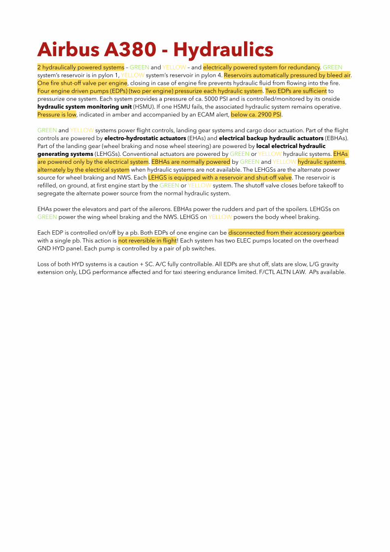
Airbus A380 - Hydraulics 2 hydraulically powered systems – GREEN and YELLOW – and electrically powered system for redundancy. GREEN system’s reservoir is in pylon 1, YELLOW system’s reservoir in pylon 4. Reservoirs automatically pressured by bleed air. One fire shut-off valve per engine, closing in case of engine fire prevents hydraulic fluid from flowing into the fire. Four engine driven pumps (EDPs) (two per engine) pressurize each hydraulic system. Two EDPs are sufficient to pressurize one system. Each system provides a pressure of ca. 5000 PSI and is controlled/monitored by its onside hydraulic system monitoring unit (HSMU). If one HSMU fails, the associated hydraulic system remains operative. Pressure is low, indicated in amber and accompanied by an ECAM alert, below ca. 2900 PSI.
GREEN and YELLOW systems power flight controls, landing gear systems and cargo door actuation. Part of the flight controls are powered by electro-hydrostatic actuators (EHAs) and electrical backup hydraulic actuators (EBHAs). Part of the landing gear (wheel braking and nose wheel steering) are powered by local electrical hydraulic generating systems (LEHGSs). Conventional actuators are powered by GREEN or YELLOW hydraulic systems. EHAs are powered only by the electrical system. EBHAs are normally powered by GREEN and YELLOW hydraulic systems, alternately by the electrical system when hydraulic systems are not available. The LEHGSs are the alternate power source for wheel braking and NWS. Each LEHGS is equipped with a reservoir and shut-off valve. The reservoir is refilled, on ground, at first engine start by the GREEN or YELLOW system. The shutoff valve closes before takeoff to segregate the alternate power source from the normal hydraulic system.
EHAs power the elevators and part of the ailerons. EBHAs power the rudders and part of the spoilers. LEHGSs on GREEN power the wing wheel braking and the NWS. LEHGS on YELLOW powers the body wheel braking.
Each EDP is controlled on/off by a pb. Both EDPs of one engine can be disconnected from their accessory gearbox with a single pb. This action is not reversible in flight! Each system has two ELEC pumps located on the overhead GND HYD panel. Each pump is controlled by a pair of pb switches.
Loss of both HYD systems is a caution + SC. A/C fully controllable. All EDPs are shut off, slats are slow, L/G gravity extension only, LDG performance affected and for taxi steering endurance limited. F/CTL ALTN LAW. APs available.

Airbus A380 - Flight Controls Primary flight control surfaces: - three ailerons per wing, - eight spoilers per wing, - one trimmable horizontal stabilizer (THS), - two elevators on each side of the horizontal tail plane and - two rudders.
Roll control is provided by 3 ailerons and spoilers 8…3 on each wing. Ailerons droop when flaps are extended. Outer spoilers and all ailerons are used for load alleviation (fully automatic). All 8 spoilers used for speed brake/gnd spoiler.
Pitch control is provided by THS and two elevators on each side of horizontal tail plane, yaw control by two rudders.
On ground, max. deflection of elevators, ailerons, rudder and spoilers (in roll mode) is indicated by green marks.
When differential braking is greater than 50%, rudder is deflected in addition to rudder pedal orders.
Elevators, ailerons, stabilizers and rudders are each driven by an active and a backup servo control. Each spoiler is driven by a single servo control. Servo controls of three types – conventional, EHA and EBHA – are powered by GREEN or YELLOW hydraulic systems or by electrical AC power.
EHAs use electrical power to generate hydraulic pressure in order to move a flight control surface. Each has a hydraulic reservoir, which can be refilled on ground only from the G or Y hydraulic systems. EHAs are used as backup. EBHAs normally operate as conventional actuators powered by G or Y hydraulic system. When hydraulic power is lost, the actuators behave as an EHA, using electrical power to generate hyd pressure. EBHAs used as active and backup.
Movement of flight control surfaces managed by six computers: three PRIMs and three SECs. One computer of any type is capable of sustaining safe a/c control down to landing. PRIMs and SECs receive data from ADIRUs (airspeed, altitude, attitude, position), SFCCs (surfaces position), LGERS (wheel speed, L/G position, ground/flt condition) and hydraulic sensors (systems status). In addition, PRIMs receive data from accelerometers and gyros (load factor), both ISIS to monitor ADRs, RAs, FQMS (weight & CG) and WBBC (weight & CG).
2 flight control data concentrators (FCDC) acquire flight control data for display, warning, maintenance & recording.
The PRIMs: - compute all flight control laws and characteristic speeds, - compute the load alleviation function, - host the flight envelope protection, - control the surfaces and - host autopilot, flight director and auto thrust.
The SECs: - compute the direct law, - control the surfaces and - control the rudder trim (SEC 1 and 3 only).
In normal ops, one PRIM acts as master, processing flight control orders and transmitting them to other computers, which activate their related actuators. If the master PRIM is unable to provide its function, any other PRIM can replace it. If all PRIMs are lost, there is no SEC master. Each operative SEC activates its respective actuators independently.
LAF reduces fatigue and static loads on the wing. It uses all the ailerons and the outer spoilers, comes in addition to normal law and is inhibited in CONF FULL. It includes passive turbulence alleviation (PTA) and active turbulence alleviation (ATA). PTA reduces static loads in turbulence and during maneuvers by symmetrically deflecting ailerons and/or outer spoilers upward. It can be added to a roll order. ATA reduces fatigue and static loads by damping wing bending modes by symmetrically deflecting the ailerons. The order can be added to a roll order and/or a PTA order.
Normal law is modified depending on the flight phase. In ground law, lateral control is a direct relationship between control inputs and surfaces in roll and yaw with full authority. Rotation law is a direct relationship between sidestick

position and elevator position without auto trim. It also minimizes the risk of tail strike. Flight law is a load factor demand with auto trim, a roll rate demand with full flight envelope protection. It is active from lift off for roll and 5 s later for pitch (progressively during 5 s). Flare law provides a direct relationship between control inputs and surfaces, giving full elevator authority without auto trim. It is active below 100’. Derotation law operates at touchdown to provide a smooth derogation and avoid a hard nose wheel touchdown. Ground law available again after touchdown.
Low energy warning (“speed, speed, speed”) sounds when it is not possible to recover a positive flight path angle using the pitch control and thrust is not increased. It is available: - above 200’ RA for takeoff and 100’ RA for landing, - below 2500’ RA, - in CONF 2, 3, FULL and - in all F/CTL laws (if at least one ADIRS, one RA and one PRIM are available).
With auto thrust inop or not engaged, speed can reduce to Va PROT, shown at the top of amber/black band. If engaged, AP will disconnect. Pitch trim is inhibited below Va PROT. Flight control computers will maintain Va PROT if sidestick is released.
Alpha floor protection is available from liftoff down to 100’ RA. It automatically activates A/THR and commands TOGA thrust when a/c AOA is above a pre-determined threshold. Alpha floor remains available when one engine is faulty. TOGA thrust is commanded only on the symmetrical engine. When two engines are faulty (on different wings), alpha floor remains available. When triggering condition disappears and A/THR still active, mode reverts to TOGA LK.
If pilots override Va PROT using sidestick, speed can reduce to Va MAX. In normal law, flight control computers will maintain Va MAX if a pilot holds the sidestick fully aft. In this protection, normal law is modified and sidestick input becomes an AOA demand. If sidestick is released, speed will return to Va PROT to be maintained.
Overspeed warning triggered at VMO + 4 kt. Green dashes indicate activation speed for high speed protection (VMO + 10 kt). When it is activated, pitch trim is frozen, AP disconnects, max bank angle limited to 45°. If speed increases further, flight control computers send pitch up command to control surfaces. It cannot be overridden. Max speed with sidestick neutral: 350 kt, max speed with side stick full forward: 365 kt.
Under normal law, bank angle protection limits bank angle to 67° (clean) and 60° (high lift configurations). FD disappears if bank angle exceeds 45°. If sidestick is released and bank angle > 33°, a/c returns to and maintains 33°. FD reappears when bank < 40°. Auto trim is inhibited above 33° bank. In case of high speed or high AOA protection, a/c returns to wings level when sidestick is released. If high speed or AOA protections active, bank limited to 45°.
For manual landing, “pitch, pitch” warning active below 400’, “bank, bank” warning active below 100’ RA.
Command for each pair of speed brake surfaces is processed by a single computer, either a PRIM or a SEC. Maximum deflection reduced in clean config at high gross weight and high altitude. Speed brakes automatically retract if alpha floor protection activated, low speed stability active or go-around initiated. Once retracted, speed brakes remain retracted. To extend again, lever must first be set to retract position for at least 5 s. F/CTL SPD BRKs STILL EXTENDED if speed brakes extended 50 s with at least one eng above IDLE or 5 s below 800’.
A blue triangle on the slat/flap display on lower PFD indicates ground spoilers are armed. Spoilers 1…8 deploy to max and ailerons deflect full up in case of RTO at v > 72 kt. At touchdown, with at least three main landing gears compressed and thrust levers at idle, ground spoilers and ailerons fully extend. When at least one landing gear is compressed and thrust levers at idle, ground spoilers extend partially. Ground spoilers retract when at least 2 thrust levers above CLB or all thrust levers at idle and speed brake lever pushed to disarm position.
Roll control provided by spoilers 3…8 with lower deflection than when deployed as ground spoilers. Roll function has priority over speed brake function.
Only a combination of failures can result in a degradation of flight control law to alternate law, direct law or electrical backup.
In alternate law, pitch control is similar to pitch control in normal law, turn coordination and yaw damping are avail. Depending on failure, roll control is similar to roll control normal law or similar to roll control of conventional a/c, most flight control protections are lost and AP & A/THR may be operative. High AOA protection replaced by low speed stability. Nose down demand introduced to avoid further speed reduction. Low energy and stall warnings remain

available. High speed protection replaced by high speed stability. Nose up demand introduced to avoid further speed increase. On PFD speed scale, Va PROT and Va MAX are replaced by VSW (stall warning speed), high speed protection symbol replaced by amber X. Pilot can override these demands. In some failures, the stabilities are lost.
Direct law may be activated after multiple failures, e.g. 3 PRIM fault. In direct law, there is a direct relationship between sidestick and surfaces position. AP is lost, auto trim is not available, pitch trim is adjusted via pitch trim switch. Turn coordination and yaw damping are available. Protections are lost. Overspeed, stall and low energy warnings (?) remain.
In case of temporary loss of all PRIMs and SECs, the backup control system provides control and stability of the a/c through the backup control module (BCM). It controls the inner ailerons, outer elevators, THS and rudders. The BCM is powered by two backup power supply (BPS). They are electrical generators driven by the YELLOW and GREEN hyd.
Abnormal attitude law ensures a/c recovery and safe continuation of flight in case of extraordinary unpredictable event (e.g. mid-air collision) in which flight parameters go far beyond limits of protected envelope. A/C is in direct law and reverts to alternate law after recovery and for the remainder of the flight.
6 slats and 2 droop nose panels on each wing leading edge, 3 flaps on each wing trailing edge. Slats actuated by one hydraulic motor (GREEN system) and one electrical motor (ACC ESS bus). Flaps actuated by two hydraulic flaps (GREEN and YELLOW hyd). Slats monitored and controlled by two slats systems, flaps by two flaps systems. Each of the four systems has a slat (flap) control and a motor. Each system monitors slats (flaps) and its respective motor. In case of one control failure, the remaining control controls both motors of slats (flaps). Each slat flap control computer (SFCC) contains one flap and one slat control (CTLs 1 in SFCC1 and CTLs 2 in SFCC2).
When slats and flaps are extended, ailerons droop 5° to increase lift. Flaps are provided with auto retraction system (ARS: retracts flaps from 1+F to 1 at 212 kt), auto extension system (AES: in CONF 1 extends flaps to 1+F below 205 kt) and flap load relief system (FLRS: retracts flaps to next retracted position when speed exceeds VFE + 2.5 kt, available in CONF 2, 3, FULL; at VFE - 2.5 kt flaps return to selected position). Slats have alpha/speed lock function that inhibits slat retraction to zero at high AOA or low speed. Slats/flaps lever has a cruise baulk function (speed above VFE CONF 1 or altitude > 22000’, slats/flaps remain fully retracted if slats/flaps lever inadvertently moved to 1). If the flaps lever is jammed, slats/flaps can be extended one step with a strong force without pulling it out of its detent (reversible). Wing tip brakes mechanically lock slats/flaps in case of asymmetry. Protection for runaway or uncontrolled movement exists.
Pitch trim via switches on center pedestal, both must be used simultaneously, not available in normal/alternate laws. Rudder trim & reset pb not active when autopilot engaged.
F/CTL SD – aileron/elevator/pitch trim actuators indicated green: power supply available & actuator operative; amber: power supply failed; green letter amber boxed: actuator failed & power supply available
Spoiler position – green horizontal dash: max deflection indicator on ground only; green bar to top: max deflection for ground spoiler/speed brake; green bar almost to top: max deflection for roll control; orange bar with gray notch: spoiler deflected and failed; gray bar with thin orange lines: spoiler fully retracted and failed
Rudder actuators – amber letter: hydraulic power supply is failed; letter amber half boxed: hydraulic part of actuator is failed; full boxed: actuator failed.
Slat/flap motors – green: both power supplies and both motors are available; amber letter: power supply failed; letter missing: power supply data not available; boxed letter: motor failed
"RUDDER TRIM" indication on PFD slats/flaps display indicates rudder is not in neutral position; on F/CTL SD page indicates that rudder trim is failed.

Airbus A380 - Landing Gear A380-800 has one nose landing gear (NLG, two wheels), two wing landing gears (WLGs, four wheels each) and two body landing gears (BLGs, six wheels each). The NLG and rear BLG wheels have no brakes, the WLG and front & mid BLG wheels have carbon brakes. GREEN hydraulic powers the NLG and WLGs, YELLOW hydraulic powers the BLGs.
Related systems: - landing gear extension and retraction system (LGERS) - brake control system (BCS) - steering control system (SCS) - tire pressure indicating system (TPIS) - brake temperature monitoring system (BTMS) and - oleo pressure monitoring system (OPMS).
In normal operation, LGERS enables opening/closure of landing gear doors and extension/retraction of landing gear. It is only pressurized during extension and retraction phases, isolated from hydraulic pressure otherwise. LGERS has two independent and redundant landing gear control and indication systems (LGCIS 1 and 2). One LGCIS controls the operation of the extension/retraction, while the other is a backup. The backup LGCIS activates automatically if the active LGCIS fails. Control changes from one LGCIS to the other after each l/g extension. The proximity sensors give l/g and doors position to each LGCIS. The active LGCIS sends gear status and position information to ECAM (EWD & WHEEL SD), lower part of PFD and other a/c systems. Only LGCIS 1 sends position data to l/g indicator panel using additional and independent set of downlock sensors.
When normal extension of l/g fails, the l/g can be extended by gravity. When the L/G GRVTY selector is in DOWN position, doors and gears uplocks are electrically released and, when released, the doors open by gravity and the gears also extend by gravity. After l/g is downlocked, l/g doors remain open. Do not use RESET position in flight!
Two free fall control modules (FFCM A and B) control the gravity extension of the landing gear. The FFCMs are independent from the LGCIS. Then the ECAM and l/g indicator panel operate normally, l/g position remains available during gravity extension. L/G gravity extension lasts ca. 70 s.
The oleo pressure monitoring system (OPMS) measures and monitors pressure and temperature of each l/g shock absorber. An OPTS is installed in each BLG, WLG and NLG oleo. An alert appears on EWD if temperature or pressure or both are outside defined limits.
The LGCIS sends ground/flight data to (among others): - FG for engagement of AP 5 s after liftoff, - BCS for inhibition of pedal braking in flight, - cabin pressurization system for control of pressurization cycle, - FMS for activation of DONE flight phase and - flight control system for ground spoilers extension logic. LGCIS receives airspeed data from ADIRS to inhibit extension of l/g above 280 kt.
Five braking modes: normal, alternate, emergency, ultimate braking + parking brake. In normal braking, hydraulic power supplied to brake system by GREEN hydraulic for WLGs and YELLOW hydraulic for BLGs. In alternate, emergency and ultimate braking modes, hydraulic power is supplied by LEHGS and/or brake accumulators. LEHGS is independent and has its own hydraulic reservoir, generating pressure via a hydraulic electro pump. There are two LEHGS for the brake system, one for WLGs and one for BLGs. Two braking control systems (BCS 1 and 2) control normal and alternate braking modes. One is active while the other is backup. Backup automatically activates if active BCS fails. Each BCS receives electrical signals from brake pedals, AUTO BRK T.O pb (RTO), AUTO BRK LDG rotary selector and l/g lever. The active BCS computes and sends electrical orders to the hydraulic brake equipment. It also sends data to the triple pressure indicator and the ECAM for display of WHEEL SD and generation of alerts.
Landing Gear
Normal Operation Abnormal Operation
Control & Monitoring electric electric
Operation hydraulic (GREEN & YELLOW)
mechanical (gravity extension)

In normal and alternate modes, flight crew uses brake pedals. Number of brake applications is not limited, differential braking is available, AUTO BRK and A-SKID are available. No performance degradation in alternate mode (full pressure applied).
The emergency brake control unit (EBCU) controls emergency braking mode and part of ultimate braking mode (only on WLGs). EBCU receives electrical commands from brake pedals in emergency braking or PARK BRK handle in ultimate braking. It then computes and sends the related electrical orders to the alternate hydraulic brake equipment. Emergency braking activates automatically when BCS 1 and 2 are faulty or A-SKID is faulty or A-SKID sw is set to OFF or a LEHGS fails in alternate braking mode without A-SKID.
In emergency braking, flight control uses brake pedals, differential braking is available, if LEHGS is available the number of brake applications is unlimited, if LEHGS is not available the number of brake limitations is limited (hydraulic power only supplied by brake accus), AUTO BRK is not available and A-SKID is not available.
In ultimate braking, flight control uses PARK BRK handle to decelerate the a/c, brake pedals are not available. Ultimate braking is controlled by the EBCU on WLGs and PARK BRK handle on BLGs. Brake pressure auto limited to 1700 PSI on WLGs and not limited (3600 PSI) on BLGs. BLG tires may burst.
Parking brake is controlled by PARK BRK handle on BLGs if all engines are shut down or PARK BRK handle on BLGs and EBCU on WLGs if at least one engine is at N1 > 50%. LEHGS or accus supply the parking brake. If LEHGS are not available, only accus supply hydraulic power.
Braking Modes Summary
Braking mode Hydraulic power supply
Braking control
Cockpit interface
Available functions ECAM ALERT
Performance
NORMAL WLGs on GREEN BLGs on YELLOW BCS 1 or 2
- brake pedals - AUTO BRK
panel
- A-SKID - AUTO BRK - diff. braking - auto retract braking
Normal performance except if BRAKES
RELEASED displayed
ALTERNATE BLG and WLG LEHGS + ACCUs BCS 1 or 2
- brake pedals - AUTO BRK
panel
- A-SKID - AUTO BRK - diff. braking
BRAKES NORM BRK FAULT
Normal perf. except if BRAKES RELEASED
EMERGENCY
if HYD failure: BLG and WLG LEHGS +
ACCUsEBCU - brake pedals
- diff. braking - braking pressure auto
limited on all brakes (1700 PSI for takeoff, 1000 PSI for landing)
BRAKES A-SKID FAULT ON ALL L/G
if LEHGS failure: BLG and WLG ACCUs only
degraded perf., limited # of brake
app. if on ACCU only
ULTIMATE
BLG and WLG LEHGS + ACCUs EBCU
and PARK BRK
- PARK BRK handle
- full braking pressure (3600 PSI) on BLGs
- braking pressure auto limited (1700 PSI) on WLGs
BRAKES PEDAL BRAKING FAULT
if LEHGS failure: BLG and WLG ACCUs only
Degraded perf. with risk of BLG tires burst
PARKING
no ENG running: BLG LEHGS + ACCUs or BLG
ACCUs
direct from PARK BRK
panel- PARK BRK
handle
- full braking pressure (3600 PSI) applied on BLGs
N/Aat least one ENG at N1 >50%: BLG and
WLG LEHGS + ACCUs or BLG and WLG ACCUs only
EBCU and
PARK BRK
- full braking pressure (3600 PSI) on BLGs
- braking pressure auto limited (1700 PSI) on WLGs

On ground with engines not running, if the PARK BRK hydraulic pressure is low, the crew can use the ACCUS REINFLATE pb to activate the BLG and WLG LEHGS and pressurize the BLG and WLG brake accus. The triple indicator shows the lowest pressure of the BLG accus on the upper part and the L & R BLG brakes pressure on the lower part.
Runway overrun warning (ROW) and runway overrun protection (ROP) enhance pilot situational awareness, supporting pilots during final approach and landing. They optimize application of alerts to possibly trigger go-around decision (ROW) and maximum braking/recommendation to use thrust reversers (ROP function). ROW/ROP are used with pedal braking or with AUTO BRK modes LO, 2, 3 or HI on all runway conditions, BTV only on dry and wet rwy, regardless of wind and visibility conditions, landing configuration (CONF 3 or FULL), weight and balance (e.g. overweight landing) and autopilot engagement (on or off). Functions are based on permanent monitoring of a/c energy and position. They enable the crew to artificially shorten a rwy threshold and/or rwy end via OANS interface (LDG SHIFT), automatically detect ldg rwy during final approach, continuously compute landing distance based on operational landing distance (OLD), compare the results with LDA and trigger alerts if runway overrun is detected.
ROW automatically armed from 500' AGL to start of braking in classic AUTO BRK modes or pedal braking, from 300' AGL to the start of braking in AUTO BRK BTV mode. Start of braking is NLG touchdown or 5 s after MLG touchdown or ground spoiler extension. ROP is armed from start of braking to vacation of runway. ROW/ROP arming are not indicated on FMA. On final approach, OANS highlights auto-detected rwy in blue and displays two DRY and WET lines in magenta, showing the realistic stop points. On ground, when AUTO BRK activates, OANS displays estimated braking distance by a blue line and green stop bar representing predicted a/c stop location. It is not displayed during pedal braking.
ROW alerts on final approach: on PFD IF WET: RWY TOO SHORT or RWY TOO SHORT, below 200' RA aural warning "RWY TOO SHORT". ROP on ground with pedal braking MAX BRAKING and MAX REVERSE on PFD with aural alert "BRAKE ... MAX BRAKING ... MAX BRAKING" repeated as long as overrun detected. When max braking applied with pedals, aural alert "SET MAX REVERSE" repeated until full reverser deployment. If overrun still detected < 80 kt with full reverser deployed, aural alert "KEEP MAX REVERSE". In automatic braking, ROP triggers max hydraulic pressure via BCS (limited by anti-skid) and MAX REVERSE on PFD as above.
Brake to vacate (BTV) manages AUTO BRK deceleration rate at landing in order to reach a pre-selected exit. It is designed only for landing on DRY or WET runways, regardless of wind/visibility, landing configuration (CONF 3 or FULL), aircraft weight & balance (e.g. overweight landing) and with autopilot engaged or not. To configure BTV, the crew uses OANS and KCCU. To configure, EFIS CP ND mode PLAN and range ZOOM, via OANS interface select runway and exit, then arm BTV on AUTO BRK mode selector. When an exit is selected, BTV computes and displays exit information (LDA), runway occupancy time (ROT) and turnaround time calculated with idle and max reverse use. BTV
Braking modes
Conditions Status
- small number of brakes released in normal mode NORMAL BRAKING
- GREEN and/or YELLOW hydraulic failure or - excessive number of brakes released in normal mode
Automatic reconfiguration to ALTERNATE BRAKING
- BCS 1 + BCS 2 failure or - excessive number of brakes released in alternate mode or - A-SKID FAULT or - A-SKID OFF
Automatic reconfiguration to EMERGENCY BRAKING
- A-SKID manually switched off Manual reconfiguration to EMERGENCY BRAKING
- parking brake handle set ON and - ground spoilers extended and - ground speed higher than 25 kt
Manual reconfiguration to ULTIMATE BRAKING

disarms if runway or exit is modified on airport map display, pilot selects different runway in FMS when a/c is above 700' or pilot changes landing rwy below 700'.
BTV activates on ground and commands optimized deceleration rate to reach 10 kt at 65 m from selected exit. BTV displayed green on FMA, DRY/WET magenta lines disappear, green stop bar appears representing braking distance, computed in real time, to reach target speed. On long landing rolls, BTV function delays braking in order to use aerodynamic deceleration. BTV deactivates when a/c GS reaches 10 kt, crew disconnects auto brake via brake pedals or A/THR disconnect pb or ground spoilers retract. If BTV exit is within last 250 m of runway, BTV deactivates when a/c GS reaches 10 kt at distance of rwy end minus 300 m. For high-speed exits, crew should manually deactivate BTV regarding exit speed (less than 50 kt).
On runway disagree below 300' BTV is reconfigured to AUTO BRK HI, BTV/LDG RWY DISAGREE displayed on ND. If BTV function is lost before arming, the crew cannot arm BTV, BRAKES BTV FAULT is displayed (inhibited between 800' AGL and 80 kt), amber BTV memo appears in INOP SYS list. If BTV is lost while armed or active, AUTO BRK selector remains on BTV position, automatic reconfiguration to AUTO BRK HI occurs (if AUTO BRK remains operational), BRK HI displayed on FMA (blue if BTV armed or green if BTV active) and BTV symbology no longer displayed on OANS.
Steering system combines NWS (two actuators) and BWS (body wheel steering, one actuator and locking mechanism per BLG) for directional control of a/c on ground. Normal NWS powered by GREEN hydraulic, replaced by alternate NWS automatically in failure case, supplied by LEHGS and/or NWS accu. Steering performance is degraded in alternate NWS: damping of steering handwheels increases to prevent command of excessive steering rates. Number of steering commands limited in alternate NWS if LEHGS fails (NWS on accu only) or alternate NWS overheats. BWS powered by YELLOW hydraulic. In failure case, both BLGs are locked in centered position by locking mechanisms. BWS activates automatically when nose wheel angle reaches 20° and GS > 30 kt. Max body wheel angle 15° L/R.
Wheel steering control system (WSCS) controls NWS and BWS. It consists of two redundant control systems 1 and 2. One is active, the other is backup (automatically activates in case of active failure). BWS is activated during pushback or towing, when all engines are shut down, to avoid torsional stress on BLGs. Two electrical motor pumps (EMPs), located on Y hydraulic system, supply BWS actuators.

Airbus A380 - Information Sys ATC datalink system provides communication, navigation and surveillance for air traffic management services via:
- air traffic service facility notifications (AFN, initiating connection to use other applications), - controller-pilot data link communication (CPDLC, direct communication using predefined messages), - automatic dependent surveillance (ADS, information report to ATC center without pilot action) and - automatic terminal information service (ATIS, information about terminal area condition).
To interface with ATC controller, flight crew uses KCCUs, MFDs, bottom of SD for ATC MAIL BOX, ATC MSG pb and loudspeakers. ATC COM page can be selected in MFD dropdown menu or via ATC COM pb on KCCU.
When a message is received in the mailbox, visual attention getter ATC MSG pb flashes and aural signal is triggered (ring every 15 s). Light and aural signal are cancelled by pressing either of the two ATC MSG pb, selecting one of the reply buttons or printing the message.
Onboard information system (OIS) is a set of applications, electronic documentation and database. Together with onboard hardware platform NSS (network server system), it makes up the "open world", an extension of a/c systems to the outside for airline operations and users. This is firewalled from the "avionics world" linking a/c systems together in a secured environment. The NSS hosts the OIS. Both improve airline operations related to flight, maintenance and cabin operations and enable the provision of additional services for the passengers.
OIS is split into three domains: avionics, flight operations and cabin/communication. An open world diode (OWD) allows a unidirectional data flow coming from the avionics domain to the other domains. It prevents information corruption of the avionics domain.
Avionics domain contains applications dedicated to airline operational control (AOC) communication via ACARS; maintenance through E-Logbook and onboard maintenance system (OMS); documentation such as cabin crew operating manual (CCOM), configuration deviation list (CDL) and MEL; servicing (refueling tool).
Flight operations domain contains performance tools: takeoff performance application (TOPA), inflight performance application (IFPA), landing performance application (LDPA) and weight & balance application (WBA); documentation: flight crew operating manual (FCOM), MEL, aircraft flight manual (AFM) containing CDL; mission tools: electronic flight folder (EFF), flight follow up (FFU) and navigation charts.
Cabin/communication domain is dedicated to pax services (e-mail or internet access), communication management service with AOC centers and service providers and maintenance tools to support maintenance operations dedicated to cabin and communication domain.
Onboard information terminal (OIT) is controlled via the panel above the display. OIT SIDE sw is used to display applications from NSS AVNCS domain or FLT OPS domain. NSS MASTER SW (left side of overhead panel) enables cutoff of NSS power when smoke is detected in (left) upper avionics bay. GATELINK pb (top of ovhd panel) enables cutoff of wireless communications between NSS and gate.
Avionics domain includes two redundant servers, two redundant routers managing data exchange between avionics world, NSS and human machine interfaces (HMIs) and a printer. NSS DATA TO AVNCS pb allows data to flow in both directions between open world and avionics world (pressed-in, normal position) or only from avionics world to open world (OFF, pb released).
Flight operations domain mainly includes CP and FO laptops plus backup laptop (not connected to network), a router managing data exchange between avionics world, NSS and HMIs and a printer.

Airbus A380 - Fire Protection A380 has: - fire detection and extinguishing systems for engines and APU, - fire detection systems for MLG bays (these include two wing landing gear bays and two body landing gear bays), - smoke detection and extinguishing systems for cargo compartments and lavatories, - smoke detection systems for the avionics bays and the crew rest compartments and - portable fire extinguishers for the flight compartment and the cabin.
Each engine has a fire detection system with two identical loops (A and B) that monitor all sensitive zones and a fire detection unit (FDU) that receives information from booth loops. There is only one FDU that is common to all engines, to the APU and to the MLG bays. The FDU triggers visual and aural alerts when fire is detected. Each engine has two fire extinguisher bottles that discharge extinguisher agent. When fire is detected:
- CRC sounds, - MASTER WARN lights flash, - ENG FIRE ECAM is triggered, - ENGINE SD appears and - FIRE lights illuminate on ENG FIRE and ENG MASTER buttons/levers.
The affected engine can then be isolated from other systems by pressing its assigned ENG FIRE pb. When it is out:
- the aural fire warning is stopped, - the fire extinguisher squibs are armed, - the LP fuel valve is closed, - the hydraulic fire shutoff valve is closed, - the engine bleed valve is closed, - the pack flow control valves are closed and - the FADEC power supply is shut off.
After pressing the AGENT pb, the fire extinguisher agent is discharged in the engine nacelle.
The APU compartment has a fire detection system that is similar to the engine fire detection system. There is only one fire extinguisher bottle. In flight, when a fire is detected in the APU sensitive zones:
- CRC sounds, - MASTER WARN lights flash, - APU FIRE ECAM is triggered, - APU SD appears and - FIRE light illuminates on APU FIRE panel.
The APU can then be isolated from other systems by pressing its assigned APU Fire pb. When it is out:
- the APU is shut down, - the aural fire warning is silenced, - the fire extinguisher squib is armed, - the LP fuel valve is closed, - the APU fuel pump is shut off, - the APU bleed valve is closed and - the APU generators are deactivated.
After pressing the AGENT pb, the fire extinguisher agent is discharged into the APU compartment.
When a fire is detected on ground, in addition to the warnings in the cockpit:
- the APU fire light illuminates on the maintenance nose gear panel, - an external horn sounds, - the APU automatically shuts down and - the fire extinguisher agent discharges automatically into the APU compartment.

The MLG bay fire detection system has two identical loops (A and B) for each of the four bays and the FDU. When a fire is detected in any landing gear bay:
- CRC sounds - MASTER WARN lights flash, - MLG BAY FIRE ECAM is triggered and - WHEEL SD appears.
For each fire detection system, the FDU compares the information that it receives from both loops to provide visual and aural alerts. If a failure is detected in one loop, the unaffected loop continues to operate normally. In case both loops of a fire detection system fail, the fire detection of the affected system is lost if the failure interval is greater than 5 seconds OR a fire is “detected” if the failure interval is within 5 seconds. The FDU has four independent channels. The loops A and B of a fire detection system send the information to different channels of the FDU. In case a failure is detected in one channel, the unaffected channel continues to operate and the fire detection remains available.
Each avionics and IFE bay and the network server system (NSS) located in the upper bay have a smoke detection system. Each bay has two smoke detectors located in the air extraction duct of the avionics racks. A smoke detection function (SDF) receives information from the detectors of each bay. The SDF triggers visual and aural alerts when smoke is detected. If the SDF detects smoke in the IFE, the FAP also triggers an alert to the cabin crew.
When smoke is detected in any avionics bay:
- CRC sounds - MASTER WARN lights flash, - AVNCS SMOKE ECAM is triggered, - SMOKE light illuminates red on the AVNCS part of the VENT panel and - COND SD appears with associated red warning.
When smoke is detected in the IFE bay:
- CRC sounds - MASTER WARN lights flash, - IFE BAY SMOKE ECAM is triggered, - SMOKE light illuminates red on the IFEC (in flight entertainment center) pb of the ENTERTAINMENT panel.
When smoke is detected in the NSS, the SMOKE light comes on red on the NSS master switch (no ECAM alert).
The forward and aft/bulk cargo compartments have a smoke detection system with detectors located in cavities within the ceiling panels and the SDF that receives information from the detectors of each compartment. When smoke is detected, the SDF triggers visual and aural alerts and the ventilation system isolates the relevant cargo compartment. Two extinguisher bottles can discharge agent into the fwd OR aft/bulk cargo compartments. When smoke is detected:
- CRC sounds - MASTER WARN lights flash, - CARGO SMOKE ECAM is triggered, - SMOKE light illuminates red on the CARGO SMOKE panel and - COND SD appears with associated red warning.
When the assigned switch is pressed on the CARGO SMOKE panel (AGENT TO FWD or AGENT TO AFT), the agent is discharged into the affected compartment as follows: bottle 1 discharges for about 1 minute, bottle 2 then slowly discharges extinguisher to provide sufficient agent concentration for approximately four hours. When a bottle is fully discharged, the associated BTL light illuminates amber.
The flight crew rest, the lower crew rest and the upper crew rest compartments have a smoke detection system with smoke detectors located either in the ceiling of each compartment or near the air extraction ducts and the SDF. When smoke is detected, the SDF triggers visual and aural alerts and in case of the lower crew rest compartment, the ventilation shutoff valves close.
When smoke is detected in any crew rest compartment:

- CRC sounds - MASTER WARN lights flash, - REST SMOKE ECAM is triggered, - FAP automatically displays the smoke page and the associated cabin smoke alert(s).
The lower crew rest is the only compartment that has extinguisher bottles. A fire extinguishing system (FES) is located in the cabin. When the assigned switch is pressed on the FES panel, extinguishing agent is discharged into the lower crew rest compartment analog to the cargo compartment extinguishing.
The lavatories have a smoke detection system with a smoke detector in the ceiling of each LAV near the air extraction duct and the SDF, which triggers visual and aural alerts when smoke is detected. Each LAV waste bin is equipped with an automatic fire extinguishing system. When smoke is detected in an upper or lower lavatory:
- CRC sounds - MASTER WARN lights flash, - XXX DECK LAVATORY SMOKE ECAM is triggered, - FAP automatically displays the smoke page and the associated cabin smoke alert(s).
There is only one SDF for the avionics bays, the cargo compartments, the crew rest compartments and the lavatories. It has three identical channels. Only one channel is active at a time, the remaining ones are in standby. If a failure is detected in one channel, the next available channel becomes active, smoke detection remains available.
The TEST pb on the FIRE panel tests the operation of the fire detection and extinguishing system for the engines, the APU and the MLG bay. When pressed for at least 3 s and until released:
- CRC sounds - the MASTER WARN lights flash, - ECAM alerts ENG FIRE, APU FIRE and MLG FIRE are displayed, - all ENG FIRE pushbuttons illuminate red on the ENG FIRE panel, - the APU FIRE pb illuminates red on the APU FIRE panel, - all SQUIB lights of the AGENT pb illuminate white, - all DISCH lights of the AGENT pb illuminate amber and, - all FIRE lights illuminate red on the ENG MASTER panel.
The TEST pb on the CARGO SMOKE panel tests the operation of the fire detection and extinguishing system for the cargo compartment and the avionics bays. When pressed for at least 3 s and until released:
- CRC sounds - the MASTER WARN lights flash, - ECAM alerts CARGO SMOKE and AVNCS SMOKE are displayed, - the isolation valve of the ventilation system closes, - all BTL lights illuminate amber - all DISCH lights of the AGENT pb illuminate amber - all SMOKE lights of the AGENT pb illuminate red and - the AVNCS SMOKE light illuminates red on the VENT panel.

Airbus A380 - Lights Lighting system comprises cockpit lighting, exterior lighting, cabin signs and emergency lighting. Three light strips around the overhead panel provide overall shadow-free cockpit ambient lighting. There are lights on the overhead panel and under the glareshield for lighting the center pedestal; lights under the glare shield for lighting of the main instrument panel; cockpit panel integral lights; lights for pilot eye reference device, standby compass and visual ice indicator. The storm lighting function provides maximum lighting in the cockpit, main instrument panel lights and ambient lights are at maximum brightness.
CAPT and F/O stations have lateral console lights, briefcase area lights, floor area lights, a light for the map holders, lights under the glare shield for the lighting of the sliding tables and reading lights with adjustable orientation. Additionally, there are a fixed reading light for the 3rd occupant, reading lights for console and other occupants fixed lights for the coat stowage and for the avionics compartment. The L+R ambient lights provide emergency lighting in the cockpit when the a/c elec supply comes from the ESS power and the crew has set the AMBIENT LT knob to on.
The exterior lighting comprises: - three white anti-collision strobe lights (flashing alternately with the beacon), - three anti-collision beacon lights (two upper and one lower), - three navigation lights, - two obstruction lights (on ground only to make the a/c more visible to other airfield users), - airline logo lights, - wing and engine scan lights (illuminating the wing leading edges and engine intakes), - two runway turnoff lights, - four camera lights (illuminating the nose and main landing gear as well as their surrounding areas on the ground –
lights illuminate on ground if ETACS is on, RWY turnoff and camera lights extinguish automatically in flight), - landing lights, - three taxi lights (one in each wing leading edge, near the wing roots and one on the nose landing gear) and - takeoff lights.
The cabin lighting system comprises cabin decks general lighting, spotlights and stair lighting. In a non-powered a/c, the crew can light the cockpit path by battery for 60 s with a pb located under the grip left of door M1L. Another pb is located near the cockpit door. The crew can turn on the light a maximum of 10 times before the first engine start.
When set in AUTO, “FASTEN SEAT BELT”, “RETURN TO SEAT” and “NO SMOKING” illuminate automatically as soon as slats or main landing gear are extended. In the event of excessive cabin altitude, cabin lights (depending on CIDS programming) and cabin signs come on regardless of switch positions.
Emergency lights are found in the cockpit, in the cabin and on the escape slides. In normal or in emergency situations, they show the way to the exit to leave the a/c. In emergency situations, they provide basic illumination if normal illumination is lost. They operate independently from the other normal lighting, however some parts of emergency lighting are integrated into normal lighting in order to be operative for normal illumination.
The cabin emergency lighting system is designed to guide pax to exits in an emergency situation. It is independently controlled by the EMER pb on the FAPs or the EMER EXIT LT sw on the cockpit overhead panel. In the ARM position, the emergency lighting activates in case of failure of cabin lighting sys, failure in elec sys or excessive cabin altitude.

Airbus A380 - Fuel The fuel system stores fuel, monitors quantity of fuel in each tank and controls fuel transfers to:
- supply fuel to the engines and APU, - maintain the CG within limits - alleviate structural loads - control refueling & refueling - enable fuel jettison.
Fuel quantity and management system (FQMS) controls:
- fuel quantity measurement, - fuel temperature measurement, - transfer/jettison control, - refuel/defuel control and - fault detection & reporting.
Fuel is stored in the wings and in the THS. There are 11 tanks that store fuel, five (symetrically) in each wing: one outer tank (OUTR TK), one mid tank (MID TK), one inner tank (INR TK) and two feed tanks (FEED TK, outboard of mid tank and inboard/forward of inner tank). One trim tank (TRIM TK) is located in the THS. The FEED TKs are used to feed engines and APU. The other tanks are called transfer tanks and are used for fuel and load alleviation transfers. The fuel system can be considered as two independent systems (ENGINE/APU FUEL FEED and FUEL TRANSFER). There are three vent tanks: one in each wing between the OUTR TK and wing tip, and one on the right side of the THS. They allow each fuel tank to be ventilated to the atmosphere. The THS vent tank is also used as a surge tank. Two more surge tanks are located in each wing between the OUTR TK and the outboard FEED TK. They collect fuel that may overflow from any fuel tank during operation. Fuel in the wing surge tank returns to the outboard FEED TKs (1 and 4), fuel in the THS surge/vent tank return to the TRIM TK. Vent/surge tanks are not displayed on the FUEL SD.
Total usable fuel quantity is ca. 254 t based on a density of 0.785 kg/l.
A collector cell is installed in each FEED TK with a capacity of ca. 1500 kg in FEED TK 1 and 4 and 1300 kg in FEED TK 2 and 3. Each collector cell contains two identical fuel pumps: one main and one standby pump. The collector cells are kept full to prevent pump cavitation by keeping the pumps submerged. Each main pump operates continuously and feeds its respective engine. Two fuel pumps can supply fuel to all engines using the cross feed system. Each engine has a cross feed valve, allowing any main or standby pump to supply any engine. The crew can also use cross feed valves to manually correct imbalances between FEED TKs. If all engine feed pumps fail, fuel is fed by gravity.
The APU is normally fed by FEED TK 4 main pump. It can also be fed by any main/standby pump or by the APU feed pump. If the ENG 4 pumps are not running or fuel pressure is too low for APU to operate correctly and the FQMS detects no damage to the APU fuel line, the APU feed pump operates automatically. It is not displayed on FUEL SD.
The transfer tanks have four automatic transfer functions: load alleviation, main transfers (to fill FEED TKs), CG transfers (to control CG) and cold fuel transfers (to avoid fuel freezing in outer tanks). Two additional transfers may be selected: refuel/defuel on ground and jettison in flight. For these transfers, the system uses two independent "galleries", a FWD and an AFT gallery. Each gallery has pipes, transfer pumps (XFR PMPs) and valves.
Trim pipes connect the TRIM TK to the AFT and FWD galleries. Each wing tank has two inlet valves, one connected to the FWD, the other to the AFT gallery. TRIM TK has two inlet valves connected to the FWD and/or AFT gallery. In the MID, OUTR and TRIM TKs, each inlet valve can also be used as an outlet valve. In each wing, an emergency outer tank transfer valve connects the OUTR TK to the outboard FEED TK. These are normally closed. Trim tank isolation and inlet
Maximum fuel quantities (kg)
OUTR TK outboard FEED TK MID TANK INR TK inboard FEED TK TRIM TK
8100 21680 28620 36220 23040 18600

valves allow fuel to be transferred AFT on ground and FWD on ground and in flight. The trim tank isolation valve is normally closed during takeoff and landing.
In normal operation, the FWD gallery is used for main transfers from INR, MID and OUTR TKs to FEED TKs or for load alleviation transfers to and from OUTR TKs; the AFT gallery and trim pipe are used for CG and main transfers from TRIM TK. Therefore, a main transfer on the FWD gallery may occur at the same time as a CG transfer on AFT gallery. In case of failure in one of the gallerias, the other gallery automatically takes over for alternate fuel transfers.
FWD and AFT galleries are interconnected during refueling, refueling, jettison and workaround (alternate transfer).
On ground, OUTR TKs are not completely filled (only 50% of maximum quantities, unless more required for flight) to reduce structural strain by engine bending moment. In flight, maximum fuel is maintained in OUTR TKs as long as possible to reduce upward bending moment of lift. To achieve this, load alleviation transfer of fuel from INR (MID if INR empty) to OUTR TKs is performed after takeoff. Before landing, load alleviation transfer from OUTR TKs occurs if OUTR TK filled to more than 50% capacity. To alleviate excessive loads in the tail, load alleviation transfer also occurs from TRIM TK before landing. Outer tank fuel temperature may decrease faster than in the other tanks. To avoid fuel freeze, cold fuel transfer is automatically done from outer tanks to FEED TKs if temperature of fuel in any OUTR TK is less than -35°C and any feed tank content is less than 18000 kg. COLDFUEL OUTR TK XFR memo appears on EWD.
Main transfer from INR TKs to FEED TKs starts when FEED TKs content reach a threshold value. FEED TK quantities are maintained between threshold and threshold + 1000 kg. When INR TKs are empty, main transfer from MID TKs starts.
CG is maintained forward of AFT limit by fuel CG transfer from TRIM TK. FWD XFR IN PROGRESS memo appears on EWD when any transfer from TRIM TK occurs. Automatic transfer from TRIM TK is either load alleviation transfer when required time to destination (RTD) less than 78 min or below FL245 if RTD not available OR a main transfer when any feed tank reaches 6000 kg with INR and MID TKs empty. Transfer stops when TRIM TK is empty (TRIM TK XFRD memo appears on EWD).
Then, transfer from OUTR TKs starts. It is either cold fuel transfer, load alleviation transfer from OUTR TKs to INR, MID or FEED TKs when RTD < 28 min. and fuel quantity in any OUTR TK > 4000 kg (or below FL245 if RTD not avail) OR a main transfer from OUTR TKs to FEED TKs (INR, MID and TRIM TKs empty). This main transfer occurs to maintain FEED TKs content between 4000 and 4500 kg. OUTR TK XFR IN PROGRESS appears on EWD when any transfer from OUTR TKs occurs. OUR TKs XFRD memo appears on EWD when OUTR TKs are empty.
As a general rule, in normal operation, as soon as one transfer tank is empty, there is no transfer of fuel in it afterward.
Jettison valves connected to the AFT gallery allow fuel to be jettisoned. Fuel is jettisoned simultaneously from all transfer tanks. Fuel in FEED TKs cannot be jettisoned. ARM and ACTIVE pb are used for arming and activating the jettison system. JETTISON IN PROGRESS memo appears on EWD. EMER OUTR TK XFR pb activates different types of gravity transfer from OUTR TKs to FEED TKs 1 and 4 via emergency outer tank transfer valves only or to FEED TKs 1...4 via emergency outer tank transfer valves and one or both galleries via inlet/outlet valves. EMER OUTR TK XFR pb is used in case of rotor burst to recover outer tank fuel by gravity if both galleries have been broken or in some other failure cases (e.g. electrical emergency configuration.
During manual transfer from outer tanks, if any outer tank pump is deselected:
- the emergency outer tank transfer valves open to supply FEED TKs 1 & 4 and - OUTR TKs supply FEED TKs 2 &3 via FWD and AFT galleries.
Expect a fuel imbalance at the end of the transfer.
In normal operation, refueling is done under full control of FQMS. It will determine the refuel distribution in order to obtain a CG of 39.5% (ground CG target). During refueling, REFUEL IN PROGRESS memo appears on the EWD. The REFUEL pb enables activation of refuel operation from the cockpit. In case of ZFW change after refueling, the AUTO GND XFR pb enables redistribution of fuel in order to obtain ground CG target.
Fuel quantity indications: green (normal range), amber double dashed (accuracy degraded), underlined (not balanced), amber (low quantity), amber half boxed (some fuel in tank not usable), amber boxed (all fuel in tank not usable).

Airbus A380 - Nav/Surveillance Navigation system can be split into four main groups: air data and inertial reference system (ADIRS), radio navigation, surveillance system (SURV) and airport navigation. ADIRS includes air data inertial reference units (ADIRUs), global positioning system (GPS), standby compass and integrated standby instrument system (ISIS). Radio nav consists of radio navigation aids, including the multi-mode receiver (MMR) and radio altimeters. Surveillance includes weather radar (WXR) with predictive windshear function (PWS), terrain awareness and warning system (TAWS), transponder (XPDR) and traffic collision avoidance system (TCAS). Airport navigation is the onboard airport navigation system (OANS).
ADIRS provides air data and inertial information to CDS, FMS and some other systems like FADEC and PRIM. The a/c has three separate and identical ADIRUs. Each ADIRU is divided into an air data reference (ADR) and an inertial reference (IR) part. These parts operate independently. The failure of one system will not cause the failure of the other. The MMR provides GPS position to the ADIRS in order to align the IR part, which also uses GPS position to compute GPIRS position. Each ADIRU is related to three air data probes: a multi function probe (MFP) that groups one pitot tube, total air temperature (TAT) and angle of attack (AOA) measurement, a side slip angle probe (SSA) and L and R integrated static probes (ISP). Separate static probes and standby pitot probe supply the ISIS. Therefore, the a/c has four fully segregated sources of air data parameters.
The ADR provides pressures, airspeed, altitude, vertical speed, Mach number, AOA and temperature. The parameters are continuously monitored to check reliability by the ADR (static pressure L/R comparison and ADR/ISIS/GPS/FADEC speed, altitude and pressure comparison) and by user systems (PRIM, FADEC and FWS). The IR provides navigation (position, velocities, accelerations), attitude (angles, rotation rates, rotation accelerations) and heading (magnetic, true, yaw) information. ADIRU 1 supplies the CM1 EFIS, ADIRU 2 the CM2 EFIS, ADIRU 3 is standby to either EFIS system.
In case of unreliable speed indications, backup speed and altitude indication are available on both PFDs by switching off the 3 ADRs. The back up speed scale (BUSS) appears based on the a/c AOA and on slat/flap config from SFCC. Its colors indicate (from top) speed above VMAX with decreased load margin (red), speed between VMAX with decreased load margin and VMAX with normal load margin (amber/red), normal speed range between VLS and VMAX (green), speed between VLS and VSW (amber/red) and stall speed area (red). A/C AOA/speed must remain in the green area. Target speed is indicated by a green bug, current speed by a fixed yellow horizontal bar with yellow triangle. BUSS is designed for a load factor of 1, roll maneuvers must be flown with care. FPV is still available with triple ADR failure. Backup altitude is based on GPS. No vertical speed indication is available.
Two MMRs receive data from GPS satellites and ground stations. They use two GPS antennas, one localizer antenna and one glideslope radome antenna. Both MMRs receive data from both FMS, three IRS, GPS, LOC and G/S antennas. They send data to PRIMs, ADIRS, SURV, OANS calculators, MFDs, PFDs, NDs, ISIS and cockpit clock. Lateral and vertical deviations are computed for each landing system and sent to the PRIMs for flight guidance and to the PFDs and NDs for display. Below 700', the PRIMs send the MMRs a command to freeze ILS or FLS parameters. In case all FMCs fail, the RMPs provide the MMRs with ILS frequency and course if standby nav is selected.
For NPA flown with the FLS function, the FMS provides the FLS beam parameters and a/c position to the MMRs. This allows the MMRs to build pseudo LOC and G/S deviations and to send these data to PRIMs, PFDs and NDs. LOC and G/S deviations are also sent to the SURV system and used to generate GPWS alerts.
The A380 has two VOR receivers, two DME, two ILS receivers included in the MMRs and two ADF receivers (optional).
3 radio altimeters (RA) provide height of the a/c above ground. There is no control for the RAs, they are automatically on when the a/c is powered. Their information is used in the auto flight guidance (autoland), by the flight control system for definition of flight control law modes, for radio height callouts and display and in the ground proximity warning calculation. Radio height is the minimum distance between the main landing gear wheels and the ground and is displayed on both PFDs when the a/c is below 2500' AGL. Radio height announcements come through the cockpit loudspeakers even if these are turned off. Below 570' RA, a white line indicates the rising ground on the attitude display and a red ribbon indicates the ground elevation on the altitude scale. Radio height indication become amber at 400' AGL if no DH has been inserted on the MFD PERF page or at DH + 100' if inserted. DH message appears and flashes when reaching inserted DH. If autothrust is active, "RETARD" is announced at 20' during a manual landing or 10' if one AP is in autoland mode.

Onboard airport navigation system (OANS) provides the crew with an airport map on its onside ND screen. It receives data from FMS (selected runways, airports and GPS primary status), ADIRS/MMRs (IRS, GPS and GPIRS positions) and LGERS (ground/flight condition). Data is also received from FWS 1 (failure display and annunciation, flight phase data), clock (date and time to check database validity period), CMV (send video from OANS to NDs via CDS), onboard maintenance system (OMS, exchange of maintenance information and airport database). A runway approaching advisory is displayed 7 s before the a/c nose enters the runway protected area. The runway pulses between normal runway and yellow bar, the PFD displays RWY AHEAD, ARC or NAV modes show the runway identification and in PLAN mode RWY AHEAD: CHANGE MODE is displayed. The airport map can be moved with the KCCU by pressing the validation pb and simultaneously moving the trackball. In PLAN mode, the map stays at the selected position, in ARC/NAV modes it returns to the a/c symbol.
The surveillance system (SURV) groups all a/c surveillance functions into one system with an integrated control panel. It has two identical systems (SYS 1 and SYS 2), a weather radar antenna inside the nose radome, four identical combined TCAS/XPDR antennas, a SURV control panel and a SURV key on the KCCU and SURV pages on the MFD. Each system can carry out all a/c environmental surveillance functions grouped by pairs: WXR/TAWS and XPDR/TCAS.
TAWS detects terrain conflicts, displays terrain information and triggers aural and visual warnings. It has a GPWS function, a terrain (TERR) function and a TAWS database. GPWS and TERR functions are controlled from the MFD. The SURV CONTROLS page allows activation/deactivation of terrain protection (TERR) function, basic GPWS function, glide slope (G/S) mode and the flap (FLAP) mode. G/S mode can also be deactivated on the SURV control panel.
On the VD, the elevation between the terrain and the a/c is a true height that does not change with barometric setting. The amber zone below the a/c symbol indicates the true vertical terrain location. It is based on the radio height and appears when lower than 5000'.
The WXR continuously scans a volume of air space ahead of the a/c and stores this data in a weather database. In AUTO, the WXR operates in flight always and on ground when the WX pb is selected on any EFIS CP and at least one engine is running. Weather is displayed on the ND between floor and roof boundaries along the a/c trajectory: in managed mode according to FMS vertical flight plan limited by AFS CP altitude and in selected mode according to the current FPA used to compute the expected flight path slope until FCU altitude. Minimum roof is 10000', maximum floor 25000', envelope +/- 4000'. Weather outside this envelope is considered "off-path" and is displayed with alternating reflectivity and black stripes. Manual management is possible for elevation, tilt, azimuth and gain.
PWS detects wind shear at least 10 s before potential encounter and alerts the crew. It is available when PRED W/S button is in AUTO position on MFD SURV CONTROLS page, a/c is on ground or below 1500' AGL and at least one engine is running. An advisory displays the predictive windshear area on the ND. A caution includes the aural warning "MONITOR RADAR DISPLAY", "W/S AHEAD" on PFD and predictive windshear area on ND. A warning includes aural "GO AROUND WINDSHEAR AHEAD" in approach and "WINDSHEAR AHEAD, WINDSHEAR AHEAD" during takeoff, W/S AHEAD on PFD and predictive windshear area on ND.
Reactive windshear detection is based on wind computation by the PRIM (i.e. not by the SURV). It is available when the a/c is not in clean config, at takeoff from 3 s after liftoff to 1300' RA and on approach from 1300' down to 50' RA. When the a/c encounters windshear conditions, an aural warning "WINDSHEAR, WINDSHEAR, WINDSHEAR" triggers and a WINDSHEAR message appears on both PFDs.
TCAS automatically selects TA mode in case of windshear, stall and TAWS alert. In TA ONLY mode, all RAs are inhibited and become Was, the ND displays TA ONLY and the PFD does not display vertical speed orders.
Standby instruments are a standby compass and two ISIS: one used as standby flight display (SFD) and one as standby navigation display (SND). Only one SFD and one SND can be displayed at the same time. In case of a DU failure, one SFD will always be displayed. ISIS receive data from one standby pitot and two standby static ports as well as MMR 1, ADIRU 1 and 3 IR part, FCU (mag/true selection).

Airbus A380 - Communication The internal communication system enables communication between CP, FO, other cockpit occupants, cabin crew, ground crew and passengers (PA announcements). External communications are possible via VHF, HF and SATCOM systems. The CP and FO can use 4 loudspeakers, 1 PTT pb on each sidestick, 2 boomsets, 2 hand microphones, 1 integrated microphone on each oxygen mask, 1 cockpit handset. Other cockpit occupants can use boomsets, a microphone with PTT pb, microphone on oxygen masks, audio control panels (ACPs).
Three radio management panels (RMPs) are installed to control the com system and include audio management. RMP 1 and 2 can also be used for backup navaid tuning. On each RMP, the crew can select the way of communication in RX/TX, tune VHF and HF frequencies, dial SATCOM telephone numbers (TEL), select voice or data mode com, monitor and select data communication parameters, enter the squawk code and adjust the volume for com and navaid identification. The RMPs exchange control data. They share selections and inputs, in order to synchronize the main displays, and enable control of all radio communication through any RMP. RMP 3 sends commands to RMP 1 or 2, which in turn sends them to the transceivers. All RMPs are directly connected to SATCOM.
To navigate through pages and modify data on the RMP, it includes 7 main pages access keys (top of the RMP), three activation/dialing keys (ADK, left of the display), three line select keys (LSKs, right of the display), a numerical keypad and two arrow keys (below the display). The audio management includes 11 transmission keys and related reception knobs and an INT/RAD sw to communicate via the boomset (bottom left of the RMP).
If RMP 1 or 2 fail, CP or FO can use RMP 3. As soon as the faulty RMP is turned off, control of communication system is recovered. If two RMPs fail, the crew can use the remaining RMP to control the communication system. As soon as both failed RMPs are turned off, the operative RMP connects to and controls all ways of radio communication.
Flight interphone enables communication between CP, FO, other cockpit occupants and ground mechanic, cabin interphone between flight crew and cabin crew (at any cabin crew station) or crew in any crew rest compartment. On ground, it is functional as service interphone and also enables communication with the ground crew at any service area. The cockpit handset can be used for cabin/service interphone. Announcements to PAX can be made from cockpit or any cabin crew station.
The com system has three VHF transceivers, each has one antenna. VHF 1 and 2 are for short range com in voice-mode only, VHF 3 mainly for short-range com in data mode (backup for com in voice mode). Two HF transceivers operate either in AM or SSB mode, they are for long-range com in voice or data mode. The two transceivers use the same antenna and cannot transmit simultaneously. If they attempt to transmit in voice mode simultaneously, the interlock function generates an audio tone.
SATCOM is for com in voice and data modes with six voice and one data channel(s). Voice channels are for cockpit and cabin telephone (TEL) com. The system has an antenna to exchange signals with ground earth stations (GES) via geostationary satellites.
Selective calling (SELCAL) identifies incoming VHF or HF calls that have an aircraft-specific SELCAL code. Visual and aural alerts are triggered: on the RMP (CALL light on related transmission key flashes amber), reset (RST) key flashes amber and a buzzer sounds in the cockpit.

Airbus A380 - Air Conditioning Two packs are supplied with air from engines, APU or HP ground air units. Each pack has two pack valves that regulate the quantity of hot bleed air that flows into each pack, one heat exchanger using external air and two cooling units (air cycle machines, ACM). If both ACM fail, bleed air is cooled by the heat exchanger only (bypass mode). Each pack and its related valves are controlled by one pack controller. The controllers have two independent channels, of which each can control one entire pack. If the entire controller fails, the associated pack fails.
On ground, LP air carts can supply conditioned air to the aircraft directly via the mixer unit. These are not displayed on the BLEED and COND SD. Four ventilation fans recirculate air to the mixer unit (primary fans). Additionally, nine ventilation fans blow air from the upper deck and recirculate it in the upper and main decks (secondary fans). there are 18 controllable zones in the a/c: cockpit, 7 zones in upper deck, 8 zones in main deck, 2 cargo zones (BULK and FWD) and the crew rest compartment. The temperature of the cockpit and each cabin zone is controlled by the temperature controller. It has two independent channels, each channel can control all zones.
If both packs fail, the mixer unit can receive air directly from outside the a/c through two emergency RAM air inlets.
Air conditioning and ventilation of FWD and BULK cargo are fully automatic. AFT cargo is not air conditioned, but ventilated by the BULK circuit. Air from the cabin enters the BULK compartment through an inlet isolation valve. An extraction fan extracts air, discharging it overboard through the outflow valves. A heater heats the air that flows into the BULK compartment, if required. Air from the cabin enters the FWD compartment through several inlet isolation valves, extraction is analog to the BULK compartment. Temperature of FWD compartment is adjusted by adding hot air from the bleed system through a trim air valve or cold air from the mixer unit.
The pressurization system automatically regulates cabin pressure and is done via control of four outflow valves during all flight phases: two in the forward part, two in the aft part of the a/c. Each valve is driven by a single electrical motor and has its own outflow valve controller. The controllers operate in automatic control mode, backup mode or manual control mode. In automatic mode, they automatically manage cabin altitude and vertical speed. If automatic mode of three controllers fails, the automatic mode of the remaining one controls all four outflow valves.
On ground before takeoff, all outflow valves are open to make sure there is no differential pressure between the inside and outside of the a/c. During takeoff roll, a delta-P of 0.1 PSI is established to allow a smooth variation of cabin v/s after takeoff. If the a/c does not climb after t/o, the cabin altitude stops climbing (pressurization abort phase). During climb, in NAV mode, climb altitude profile and v/s are a function of a/c flight profile. In HDG mode, they are a function of a/c altitude and v/s. Cabin v/s is limited to 1000 fpm. During cruise, the cabin altitude is regulated not to exceed 7500' (delta-P ca. 8 PSI). During descent, cabin v/s is controlled to reach an altitude slightly below landing field elevation prior to landing (limited to -300 fpm). After landing, all outflow valves open to depressurize the cabin.
If automatic control mode of all four outflow valve controllers fails, cabin pressurization system can be operated in manual mode. FMS data (ldg elevation) are lost, outflow valve controllers use cabin pressure info from assigned pressure sensors and external pressure information. Manual control mode of cabin altitude is used. Only in case of SMOKE/FUMES REMOVAL, manual control mode of cabin vertical speed is used. Altitude mode has priority over v/s mode. If auto and manual control modes of one outflow valve controller fail, its associated outflow valve closes, but there is no operational impact.
Two negative relief valves in the aft pressure bulkhead operate mechanically to prevent excessive negative differential pressure. Two cabin air extract valves in the aft pressure bulkhead pneumatically operate to prevent excessive positive or negative cabin pressure. They can be manually opened if requested during the smoke removal procedure.
Two ventilation controllers (FWD/AFT) control/monitor ventilation systems for cockpit/cabin zones, IFE bay, FWD cargo, pack bays & BULK/AFT cargo with two independent channels, each of which can control its related controller. Two avionics ventilation circuits (L/R) with one controller cools cockpit panels, main & upper avionics bays. On ground, avionics ground cooling cools air blown in the two circuits. Two fans blow recirculated air from cabin into various cockpit panels and equipment racks and a fan extracts air through overboard valve or extract valve for discharge overboard automatically when a/c is powered. In case of insufficient ventilation, a backup valve opens to supply cold air from air conditioning mixer unit.
IFE bay ventilated by recirc fan, extracted & discharged through outflow valves; backup by cold air from mixer unit. Pack bay areas ventilated by external air (pneumatically operated fans on ground, inlets in belly fairing in flight).

Airbus A380 - Ice & Rain Prot. Ice protection system allows unrestricted operation of the a/c in icing conditions. It protects critical areas of the a/c against ice. Each engine has its own anti-ice system with an independent hot bleed air source. An anti-ice valve on each engine enables the flow of hot air.
Hot air from the pneumatic system can be used to prevent ice accretion on slat 4. In each wing, wing anti-ice valves enable the flow of hot air. If wing anti-ice is activated, the WING A-ICE message is displayed in white and its related arrow in green on the BLEED SD.
The cockpit windows , multi function probes (MFP), integrated static probes (ISP), side slip angle probes (SSA) and standby pitot/static probes) are electrically heated, fully automatically as soon as any engine is started. The systems can be manually activated before engine start via the PROBE/WINDOW HEAT pb.
Electrical heating elements are also installed on the drain masts. The water lines are automatically heated to prevent ice formation, which could lead to damage and/or obstruction of the water lines.
The ice detection system has two ice detectors that measure ice accretion. If these sensor sense icing or severe icing conditions, the information is sent to the anti-ice control system for display to the flight crew. The anti-ice control system monitors and controls engine anti-ice, wing anti-ice, window heat and rain repellent. It has two anti-ice control units (AICU 1 and 2).
Two visual ice indicators give the flight crew a visual backup to the ice detection system. They can be illuminated with the ICE IND light.
Wing and engine anti-ice can be selected from the ANTI ICE panel. On ground, if wing anti-ice is selected, the wing anti-ice valves will open for 30 s. Wing anti-ice will then be inhibited for 10 min, provided the a/c is not in flight. Wing anti-ice is also inhibited during takeoff until thrust reduction.
Engine and wing anti-ice activation are confirmed by an indication on the right top on the EWD (NAI/WAI) and on the memo (ENG A-ICE and WING A-ICE). The memo displays ICE NOT DETECTED if wing and/or engine anti-ice was manually selected and the ice detectors have not detected any ice for approximately 2 min.
The rain repellent level is indicated on the DOOR SD. LO indicates there is sufficient rain repellent fluid for three approaches in heavy rain.

Airbus A380 - Oxgen Cockpit is supplied by a fixed oxygen system. It has one or more (optional) high pressure oxygen bottle(s), a supply valve, up to five crew oxygen masks and an overboard discharge indicator (normally green). Cabin is supplied by a second fixed oxygen system. It has high pressure oxygen bottles, two regulators with supply valves, two supply lines (one for main deck, one for upper deck), masks and an overboard discharge indicator. In case one of the supply lines rupture in the engine burst area, both related shutoff valves will automatically isolate the affected section of the supply line. Oxygen is still supplied to the masks in the affected area via interconnected lines from the other supply line. The cabin fixed oxygen system activates automatically when the cabin altitude is above 13800' or manually by pressing the MASK MAN ON pb. Masks are stowed in containers above PAX seats, in each LAV, in each galley, at each cabin crew station, in both stairs and in the crew rest compartment. Pre-recorded instructions are automatically broadcast when the masks are released.
Protective breathing equipment (PBE, Rauchschutzhauben) are available throughout the cockpit and the cabin. They can be used in case of smoke, fire, noxious gases or cabin depressurization. They protect the user's eyes and respiratory system for 15 min, enable the user to leave the station and to communicate. They can be used below 25000' cabin altitude.

Airbus A380 - Doors A380-800 has 14 passenger exit and 2 emergency exit doors (main deck over the wings). They are normally controlled electrically, but can be controlled manually. It has 3 cargo doors (FWD, AFT & BULK). FWD and AFT open outward and upward, are hydraulically operated by the G system (can be operated manually with a hand pump). BULK is operated manually by handles outside the hold, opens inward and upward. Main avionics bay access: from the outside 1 avionics bay hatch, from the FWD cargo compartment 2 doors and from the cockpit a hatch. Avionics access door opens inward and upward, can be manually opened or closed by an outside and an inside handle.
The cockpit has 1 cockpit door and 2 emergency exits (sliding windows). An escape rope is located above each sliding window. In case of rapid decompression in the cockpit, the upper decompression panel opens and the cockpit door unlocks automatically (by pressure sensors).
Each windshield or window in the cockpit has three layers. The external layer is not a structural layer. The two internal layers are structural layers. There is a heating film between the external layer and the internal layers. Each heating film is powered by two heat bars. These also enable the crew to detect if a structural layer is damaged in case of a cracked window (cracks on exterior side: structure not affected; cracks on cockpit side: at least one structural layer damaged).
Doors and slides management system (DSMS) informs DOOR SD to monitor status of:
- sliding windows (locked or not locked), - avionics door (locked or not locked), - cargo doors (locked or not locked), - main deck passenger doors (locked or not locked), - upper deck passenger doors (locked or not locked) and - slide armed indications.
If a main deck door, an upper deck door or a cargo door is not locked when at least one engine is running, the related name appears in amber.