Abstract A fiber optic, photodiode design for detecting horizontal eye movement in the rhesus...
27
Abstract Abstract A fiber optic, photodiode A fiber optic, photodiode design for detecting horizontal design for detecting horizontal eye movement in the rhesus macaque eye movement in the rhesus macaque monkey while in the fMRI is monkey while in the fMRI is developed and tested. Light from developed and tested. Light from an infrared laser source with an an infrared laser source with an output of 40 mW is directed via output of 40 mW is directed via fiber optic cable to reflect off fiber optic cable to reflect off of the eye. A photodiode receives of the eye. A photodiode receives the reflected light by way of a the reflected light by way of a fiber optic cable and generates a fiber optic cable and generates a voltage based on the intensity of voltage based on the intensity of light received. Maximum light received. Maximum reflection achieved was 35%. reflection achieved was 35%. Output based on a single source Output based on a single source cable and single detector cable is cable and single detector cable is not linear. not linear.
-
Upload
marion-bertina-chapman -
Category
Documents
-
view
219 -
download
2
Transcript of Abstract A fiber optic, photodiode design for detecting horizontal eye movement in the rhesus...

AbstractAbstractA fiber optic, photodiode design for A fiber optic, photodiode design for
detecting horizontal eye movement in detecting horizontal eye movement in the rhesus macaque monkey while in the the rhesus macaque monkey while in the fMRI is developed and tested. Light from fMRI is developed and tested. Light from an infrared laser source with an output of an infrared laser source with an output of 40 mW is directed via fiber optic cable to 40 mW is directed via fiber optic cable to reflect off of the eye. A photodiode reflect off of the eye. A photodiode receives the reflected light by way of a receives the reflected light by way of a fiber optic cable and generates a voltage fiber optic cable and generates a voltage based on the intensity of light received. based on the intensity of light received. Maximum reflection achieved was 35%. Maximum reflection achieved was 35%. Output based on a single source cable Output based on a single source cable and single detector cable is not linear. and single detector cable is not linear.

MotivationMotivationMotivationMotivation
Dr. Populin, a member of the Dr. Populin, a member of the anatomy department at the anatomy department at the University of Wisconsin – Madison, University of Wisconsin – Madison, wishes to study the neural wishes to study the neural mechanism behind the spatial mechanism behind the spatial visual attention in the cerebral visual attention in the cerebral cortex of macaque monkeys cortex of macaque monkeys through functional magnetic through functional magnetic resonance imaging, allowing for resonance imaging, allowing for analysis of behavioral processes.analysis of behavioral processes.
Dr. Populin, a member of the Dr. Populin, a member of the anatomy department at the anatomy department at the University of Wisconsin – Madison, University of Wisconsin – Madison, wishes to study the neural wishes to study the neural mechanism behind the spatial mechanism behind the spatial visual attention in the cerebral visual attention in the cerebral cortex of macaque monkeys cortex of macaque monkeys through functional magnetic through functional magnetic resonance imaging, allowing for resonance imaging, allowing for analysis of behavioral processes.analysis of behavioral processes.

Problem StatementProblem Statement
The client requests a The client requests a detection device to detection device to measure horizontal measure horizontal monkey eye movement in monkey eye movement in a functional Magnetic a functional Magnetic Resonance Imaging (fMRI) Resonance Imaging (fMRI) environment.environment.
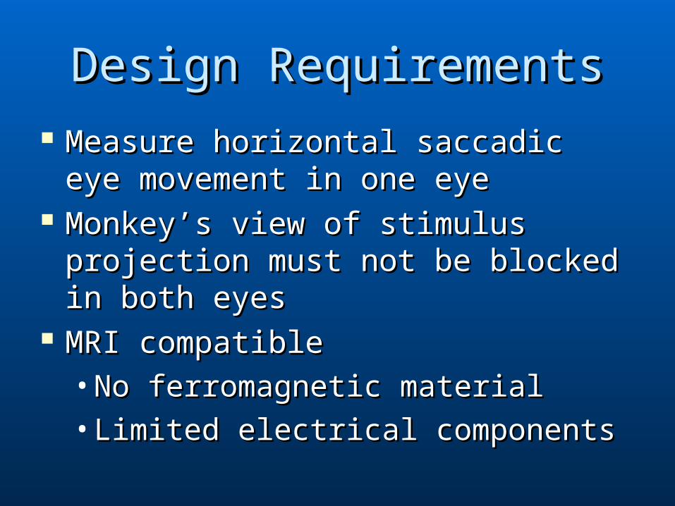
Design RequirementsDesign Requirements Measure horizontal saccadic eye Measure horizontal saccadic eye
movement in one eyemovement in one eye Monkey’s view of stimulus Monkey’s view of stimulus
projection must not be blocked in projection must not be blocked in both eyesboth eyes
MRI compatibleMRI compatible•No ferromagnetic materialNo ferromagnetic material•Limited electrical componentsLimited electrical components

BackgroundBackground Eye MovementEye Movement
• Smooth pursuit eye movements are made when Smooth pursuit eye movements are made when the eye follows a moving objectthe eye follows a moving object
• Saccadic eye movement consists of rapid jumps in Saccadic eye movement consists of rapid jumps in angular direction of eye to redirect line of sight angular direction of eye to redirect line of sight when viewing stationary objectswhen viewing stationary objects
• Our device will record saccadic eye movementsOur device will record saccadic eye movements
(Kowler, 1990)

BackgroundBackgroundfMRIfMRI
• Coil aligns atomic Coil aligns atomic nuclei with magnetic nuclei with magnetic fieldfield
• As brain activity As brain activity increases, increases, oxygenated blood oxygenated blood flow to active areas flow to active areas increasesincreases
• Waisman center fMRI Waisman center fMRI has a magnetic has a magnetic strength of 3 Teslastrength of 3 Tesla
(Kimmig et al. 1999)

Design #1: Copper Eye CoilsDesign #1: Copper Eye Coils
Skalar Medical BV. www.skalar.nl.
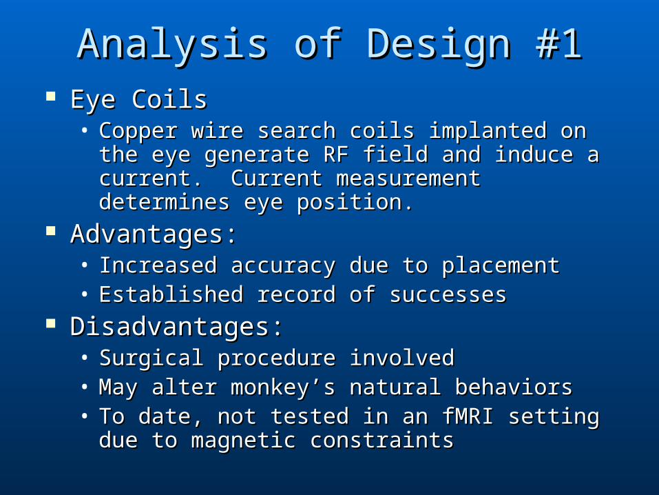
Analysis of Design #1Analysis of Design #1 Eye CoilsEye Coils
• Copper wire search coils implanted on the eye Copper wire search coils implanted on the eye generate RF field and induce a current. generate RF field and induce a current. Current measurement determines eye Current measurement determines eye position.position.
Advantages:Advantages:• Increased accuracy due to placementIncreased accuracy due to placement• Established record of successesEstablished record of successes
Disadvantages:Disadvantages:• Surgical procedure involvedSurgical procedure involved• May alter monkey’s natural behaviors May alter monkey’s natural behaviors • To date, not tested in an fMRI setting due to To date, not tested in an fMRI setting due to
magnetic constraintsmagnetic constraints

Design #2: Infrared Camera SystemDesign #2: Infrared Camera System
Eye camera & IR illuminator
Head coil
(Adapted from Gitelmen et al. 1999 )
Infrared camera and IR illuminator
Head coil

Analysis of Design #2 Analysis of Design #2
Infrared Camera SystemInfrared Camera System• Infrared camera used to capture eye image Infrared camera used to capture eye image
via infrared light projected by fiber optic via infrared light projected by fiber optic cablecable
Advantages:Advantages:• Non-invasiveNon-invasive• Devices currently in use in MRI on humansDevices currently in use in MRI on humans
Disadvantages:Disadvantages:• Camera electronicsCamera electronics• Frequent Detection ErrorsFrequent Detection Errors• ExpensiveExpensive

Proposed Final Design: Proposed Final Design: Photodiodes SystemPhotodiodes System
Infrared radiation is projected onto the eye Infrared radiation is projected onto the eye via a fiber optic array attached to an LED via a fiber optic array attached to an LED source outside of MRI’s Faraday cagesource outside of MRI’s Faraday cage
Two fiber optic cables carry radiation Two fiber optic cables carry radiation reflected from the eye to photodiodes reflected from the eye to photodiodes located outside of Faraday cagelocated outside of Faraday cage
Photodiodes detect incident radiation and Photodiodes detect incident radiation and produce current based on produce current based on intensityintensity of light of light

Proposed Final DesignProposed Final Design

Analysis of Final DesignAnalysis of Final Design Advantages:Advantages:
• Compatible with MRI environmentCompatible with MRI environment• Non-invasiveNon-invasive• Inexpensive relative to other methodsInexpensive relative to other methods
Disadvantages:Disadvantages:• Calibration timeCalibration time

Design ComparisonDesign Comparison
Design 1Design 1Eye CoilsEye Coils
Design 2Design 2CameraCamera
Design 3Design 3PhotodiodesPhotodiodes
InvasivenessInvasiveness 00 55 44
ExpenseExpense 22 11 55
MRI compatibilityMRI compatibility 11 33 55
Responsiveness Responsiveness 55 44 55
TotalsTotals 88 1313 1919
Based on our design matrix, we selected the photodiode system

Materials UsedMaterials Used
2 fiber optic cables (50/125 micron)2 fiber optic cables (50/125 micron) Infrared laser box (output 850nm)Infrared laser box (output 850nm) Power meter (in dB)Power meter (in dB) PVC (3/4 inch, 1 inch)PVC (3/4 inch, 1 inch) Oscilloscope (max voltage = 335 mV)Oscilloscope (max voltage = 335 mV) Sheep eyes, Rabbit eyes, MarbleSheep eyes, Rabbit eyes, Marble

Preliminary Testing: MarblePreliminary Testing: Marble Goal: To obtain infrared reflection off a Goal: To obtain infrared reflection off a
comparable spherical surfacecomparable spherical surface Results:Results:
• Angle = 96Angle = 96° between cables° between cables• 21.0 dB of reflected IR light21.0 dB of reflected IR light• Max output of IR laser Max output of IR laser
box is 81.5 dBbox is 81.5 dB

Preliminary Testing: Sheep eyePreliminary Testing: Sheep eye Goal:Goal:
• To obtain realistic reflective properties To obtain realistic reflective properties similar to those of a monkey’s eyesimilar to those of a monkey’s eye
Methods:Methods:• Used a Sheep eye (2.7 cm in diameter) Used a Sheep eye (2.7 cm in diameter)
placed in cupplaced in cup Results:Results:
• Variation in dB readings with rotation of Variation in dB readings with rotation of eye eye
• Unable to accurately measure angle of Unable to accurately measure angle of displacementdisplacement

Preliminary Testing: Sheep eyePreliminary Testing: Sheep eye
Top left: Dissection and preparation of sheep eye
Bottom right: Cable arrangement during preliminary sheep eye testing

Testing Set-upTesting Set-up
Testing set-up consisted of an infrared laser box, two fiber optic cables, and an optical power meter.

Secondary Testing: Sheep EyeSecondary Testing: Sheep Eye
Goal: Find a linear relationship Goal: Find a linear relationship between angular eye displacement between angular eye displacement and voltageand voltage
Methods:Methods:• Used two half-cylinders to determine Used two half-cylinders to determine
angular displacementangular displacement• Plotted optical power output vs. angular Plotted optical power output vs. angular
displacementdisplacement

Secondary Testing: Sheep EyeSecondary Testing: Sheep Eye
Multiple views of cable and eye orientation for secondary testing with sheep eyes. Double cylinder method allowed for accurate angular displacement measurements vs. optical power output.

Standard Calibration CurveStandard Calibration Curve
Voltage (in Volts) vs. angular displacement of rhesus monkey eye (in degrees). Calibration curve provided by Luis Populin’s Laboratory

Secondary Testing ResultsSecondary Testing ResultsVertical Eye Movement
0
5
10
15
20
25
30
-20 -10 0 10 20Angle (Visual Degrees)
Ou
tpu
t (d
B)
Trial 1
Trial 2
Horizontal Eye Movement
0
5
10
15
20
25
-25 -20 -15 -10 -5 0 5 10
Angle (Visual Degrees)
Out
put (
dB)
Trial 1
Graphs depict power output (in dB) vs. sheep eye angular displacement (in degrees). Highest power outputs generally found at smaller angles of displacement.

Problems EncounteredProblems Encountered Maintaining a steady reflection across the Maintaining a steady reflection across the
surfacesurface Accurate angle measurementAccurate angle measurement Keeping the cables fixed in one positionKeeping the cables fixed in one position Sheep eyesSheep eyes
• PreservationPreservation• Shape interfered with angles of reflectionShape interfered with angles of reflection• Anatomically different from monkey eyesAnatomically different from monkey eyes
OscilloscopeOscilloscope• Obtaining a constant readingObtaining a constant reading

Proposed BudgetProposed Budget
ComponentComponent Price Price SupplierSupplier
Fiber Optic Fiber Optic Cables (FC-FC)Cables (FC-FC)
$80$80 Fiberdyne LabsFiberdyne Labs
Pigtailed Pigtailed Silicone Silicone PhotodiodesPhotodiodes
$25$25 HamamatsuHamamatsu
Fiber optic Fiber optic ArrayArray
$120$120 OpticisOpticis
Infrared Light Infrared Light SourceSource
$70$70 Ion OpticsIon Optics
TotalTotal $295$295

Future WorkFuture Work
Order components and construct Order components and construct functional prototypefunctional prototype
Test system on monkey eyesTest system on monkey eyes Integrate photodiode system with Integrate photodiode system with
client’s computer software systemclient’s computer software system

Acknowledgements and ReferencesAcknowledgements and References
Applied Science Laboratories (ASL): www.a-s-l.com
Buckner, R.L. and Logan J.M. 2001. Functional Neuroimaging Methods: PET and fMRI. In R. Cabeza and A. Kingstone (eds.) Handbook of Functional Neuroimaging of Cognition. Boston, MA: MIT Press.
Bullwinkel, P.E., 2000. Fiber optic eye-tracking system utilizing out-of-band light source. US Patent, 6,079,829 Delgado-García, J.M. 1999. Oculomotor System. Nature: Encyclopedia of Life Sciences. Nature Publishing Group.
Gazzaniga, M.S. (ed.). 1999. fMRI measurement methods. The New Cognitive Neurosciences. Boston, MA: MIT Press.
Gitelman, D.R., Parrish, T.B., LaBar, K.S., Marsel Mesulam, M. 1999. Rapid Communication: Real-time monitoring of eye movements using infrared video oculography during functional magnetic resonance imaging of the frontal eye fields. NeuroImage. 11: 58-65.
Judge, S.J., Richmond, B.J., Chu, F.C. 1980. Implantation of magnetic search coils for measurement of eye position: An improved method. Vision Research. 20: 535 538.
Kimmig, H., Greenlee, M.W., Huethe, F., Mergner, T. 1999. MR-Eyetracker: a new method for eye movement recording in functional magnetic resonance imaging. Exp Brain Res. 126: 443-449.
Kowler, E. (ed.). 1990. Eye Movements and Their Role in Visual and Cognitive Processes. Reviews of Oculomotor Research. 4: 1-70.
Reulen, J.P.H., Marcus, J.T., Koop, D., de Vries, F.R., Tiesinga, G., Boshuizen, K., Bos, J.E. 1988. Med. & Biol. Eng. & Comput. 26: 20-26.
Richards, J.E. 1990. Eye position prospectus for measuring eye movements. http://jerlab.psych.sc.edu/pdf/eyeposition.pdf
Skalar Medical BV. www.skalar.nl.
Special thanks to:Professor Leon McCaughan, ECE ProfessorSeth McGee, Biocore Lab Manager