
ABB_PCM600_Using Tool Components.pdf
278
GUID-94783A77-FF24-42FE-90DC-0414357A733B Using the tool components This chapter provides information about all the tool components and their usage in PCM600. ABB Lifecycle Services Application Configuration Common read/write Communication Management Starting Configuration Wizard Disturbance Handling Event Viewer Graphical Display Editor Hardware Configuration IEC 61850 Configuration IED Compare IED Configuration Migration IED user management Injection Commissioning tool License Update tool Parameter Setting Reporting Scheduler Signal Matrix Signal Monitoring ABB.PCM.TOOLS.PCMLCT.LCT ABB Lifecycle Services The ABB product data registration system is used for collecting all the composition information throughout the IED's life cycle, and adding them in ABB's data server. ABB lifecycle services collects product data, such as product hardware, product software and site information related to an IED. The data is used for improving the products, services and the customer satisfaction. PCM600 Online Help PCM600 Protection and Control IED Manager © Copyright 2013 ABB. All rights reserved. PCM600 Online Help PCM600 Protection and Control IED Manager Página 1 de 278 Using the tool components 02/01/2015 file:///C:/Users/Santiago/AppData/Local/Temp/~hh3C0F.htm
-
Upload
gustavojanito -
Category
Documents
-
view
24 -
download
6
Transcript of ABB_PCM600_Using Tool Components.pdf
GUID-94783A77-FF24-42FE-90DC-0414357A733B
Using the tool components
This chapter provides information about all the tool components and their usage in PCM600.
ABB Lifecycle Services
Application Configuration
Common read/write
Communication Management
Starting Configuration Wizard
Disturbance Handling
Event Viewer
Graphical Display Editor
Hardware Configuration
IEC 61850 Configuration
IED Compare
IED Configuration Migration
IED user management
Injection Commissioning tool
License Update tool
Parameter Setting
Reporting
Scheduler
Signal Matrix
Signal Monitoring
ABB.PCM.TOOLS.PCMLCT.LCT
ABB Lifecycle Services
The ABB product data registration system is used for collecting all the composition
information throughout the IED's life cycle, and adding them in ABB's data server. ABB
lifecycle services collects product data, such as product hardware, product software and site
information related to an IED. The data is used for improving the products, services and the
customer satisfaction.
PCM600 Online Help PCM600
Protection and Control IED Manager
© Copyright 2013 ABB. All rights reserved.
PCM600 Online Help PCM600
Protection and Control IED Manager
Página 1 de 278Using the tool components
02/01/2015file:///C:/Users/Santiago/AppData/Local/Temp/~hh3C0F.htm

Collecting ABB product composition data from IED
Writing collective IED site information
Opening Clionet™ File Storage
Parent topic: Using the tool components
ABB.PCM.TOOLS.PCMLCT.LCT.COLLECTDATA
Collecting ABB product composition data from IED
The IED must support the ABB Lifecycle Service tool function to collect the product
composition data. If the data collection is already ongoing for a specific IED, the collection
menu item is disabled.
1. Ensure that the connection between the IED and PCM600 is working.
2. Project Explorer, right-click the IED object in the object tree.
3. Click Lifecycle Handling>Collect IED Composition Data on the shortcut menu. A
message indicating the status of the composite data collection is displayed.
If the composition data is successfully collected, the ABB Lifecycle Service tool sends the IED
data to the life cycle traceability server. If collecting the product composition data fails,
ensure that the connection between the IED and PCM600 is working properly and try again.
Parent topic: ABB Lifecycle Services
GUID-694BC985-38DF-4607-B41B-2D95680CFF53
Writing collective IED site information
The IED site information can be written to the IED by using the Parameter Setting tool. Use
the Site Information tool to write the site information to several IEDs at the same time.
1. Ensure that the connection between the substation and PCM600 is working.
2. Right-click the substation object in the object tree in Project Explorer.
3. Select Site Information Tool from the shortcut menu. The Site Information Tool
dialog box opens.
4. Define the customer name and the substation address. Select the correct country from
the Country drop-down list.
© Copyright 2013 ABB. All rights reserved.
PCM600 Online Help PCM600
Protection and Control IED Manager
© Copyright 2013 ABB. All rights reserved.
PCM600 Online Help PCM600
Protection and Control IED Manager
Página 2 de 278Using the tool components
02/01/2015file:///C:/Users/Santiago/AppData/Local/Temp/~hh3C0F.htm
5. Click Write to IEDs to write the site information to IEDs located below the selected
substation object.
6. The Writing Site Information to IEDs dialog shows the writing progress.
� To stop the writing process, click Cancel.
The Writing Site Information to IEDs dialog box shows the writing progress.
The written collective IED site information is shown in the Output window.
Parent topic: ABB Lifecycle Services
GUID-6D36F9CE-AB58-4571-8F66-C824D854C767
Opening Clionet™ File Storage
The Clionet™ File Storage is an online backup database for the IED configuration files and
disturbance recordings.
1. Ensure that the Internet connection is available.
2. In Project Explorer, right-click the specific IED object in the object tree.
3. Click Lifecycle Handling>Clionet™ File Storage on the shortcut menu.
4. For relay level access, enter the relay serial number and postal code registered for it in
the Life Cycle Traceability tool, and click Login.
Parent topic: ABB Lifecycle Services
ABB.PCM.TOOLS.PCMAPPLICATIONCONFIGURATION.APPLICATIONCONFIGURATION
Application Configuration
The application configuration tool is a generic tool used for configuring the IEDs.
Starting application configuration
Configuration handling
Validation handling
MainApplication handling
Page handling
Function block handling
Connections
© Copyright 2013 ABB. All rights reserved.
PCM600 Online Help PCM600
Protection and Control IED Manager
© Copyright 2013 ABB. All rights reserved.
PCM600 Online Help PCM600
Protection and Control IED Manager
Página 3 de 278Using the tool components
02/01/2015file:///C:/Users/Santiago/AppData/Local/Temp/~hh3C0F.htm

Variables
Edit features
Composite function block editor
Creating composite function block types from function block instances
Composite function block handling
MainApplication template manager
Hardware Channel
Comparing application configuration
Online Monitoring
Online signal forcing
Glue Logics
Constant signals
Signal user-defined name (Signal UDN)
Interaction with Signal Matrix Tool
Interaction with Parameter Setting
Setting Application Configuration tool preferences
Closing Application configuration
Licensing
Parent topic: Using the tool components
ABB.PCM.TOOLS.PCMACT.ACT.STARTACT
Starting application configuration
The application configuration can be started using the shortcut menu in the plant structure or
from the PCM600 main menu.
1. Select the IED from the plant structure.
2. To select application configuration:
� Right-click any IED in the PCM600 object tree and select Application
Configuration from the shortcut menu list.
� Select Tools>Application configuration from the PCM600 main menu.
Parent topic: Application Configuration
© Copyright 2013 ABB. All rights reserved.
PCM600 Online Help PCM600
Protection and Control IED Manager
© Copyright 2013 ABB. All rights reserved.
PCM600 Online Help PCM600
Protection and Control IED Manager
Página 4 de 278Using the tool components
02/01/2015file:///C:/Users/Santiago/AppData/Local/Temp/~hh3C0F.htm
ABB.PCM.TOOLS.PCMAPPLICATIONCONFIGURATION.APPLICATIONCONFIGURATION.CONFIGURATIONHANDLING
Configuration handling
The configuration option facilitates many operations which are possible only in the
configuration mode of Application Configuration Tool.
Opening a configuration
Navigating in a configuration
Saving a configuration
Writing a configuration
Reading a configuration
Closing a configuration
Parent topic: Application Configuration
ABB.PCM.TOOLS.PCMAPPLICATIONCONFIGURATION.APPLICATIONCONFIGURATION.CONFIGURATIONHANDLING.OPENCONFIGURATION
Opening a configuration
The application configuration can be opened using the shortcut menu in the plant structure or
from the PCM600 main menu.
Using the shortcut menu in the plant structure, configuration can be opened from various
objects such as:
� IED object
� Application configuration object
� MainApp object (if the number of main applications are greater than 1)
� FunctionBlock object
1. Select any object from the plant structure.
2. To open the application configuration:
� Right-click the selected object and select Application Configuration from the
shortcut menu list.
� Select Tools>Application configuration from the PCM600 main menu.
The last saved configuration will be opened in Application Configuration Tool. If the
configuration is opened for the first time, either an empty configuration with the default main
application opens or the basic configuration is loaded if it is configured using the configuration
wizard. The basic configuration will not be displayed to the user.
If the user tries to open a configuration that is already open, there will not be any change.
However, the user can opt to open the configuration of any IED, that is, multiple instances of
Application Configuration Tool can be opened.
© Copyright 2013 ABB. All rights reserved.
PCM600 Online Help PCM600
Protection and Control IED Manager
Página 5 de 278Using the tool components
02/01/2015file:///C:/Users/Santiago/AppData/Local/Temp/~hh3C0F.htm

Parent topic: Configuration handling
ABB.PCM.TOOLS.PCMACT.ACT.CONFIGURATIONHANDLING.CONFIGURATIONNAVIGATION
Navigating in a configuration
� Use the page navigator
� Navigate through the plant structure
� Choose the MainApp tabs available for the configuration
When a particular function block object or composite function block is selected in the plant
structure, the corresponding object is selected in the Application Configuration tool.
Parent topic: Configuration handling
ABB.PCM.TOOLS.PCMACT.ACT.CONFIGURATIONHANDLING.SAVECONFIGURATION
Saving a configuration
The Save option helps to save the configuration data. The application configuration can be
saved using the toolbar, from the PCM600 main menu or using shortcut keys.
� Click the Save button from the tool bar.
� Select File>Save from the PCM600 main menu.
� Press the CTRL+S keys.
The message box displays the effect of saving other tools. After the confirmation to proceed,
the configuration is saved. A progress bar is displayed indicating the progress of saving. A
message in the output window indicates the success or failure of the save operation.
Undo and redo operation is cleared after the save operation.
Any failure in saving results in a rollback and the changes are lost.
The save option is enabled only if there are any changes in the configuration. If
© Copyright 2013 ABB. All rights reserved.
PCM600 Online Help PCM600
Protection and Control IED Manager
© Copyright 2013 ABB. All rights reserved.
PCM600 Online Help PCM600
Protection and Control IED Manager
Página 6 de 278Using the tool components
02/01/2015file:///C:/Users/Santiago/AppData/Local/Temp/~hh3C0F.htm

the save option is disabled, there are no changes from the previous saving.
Upon successful save, the plant structure is updated. If the configuration has more than one
main application, MainApp is visible in the plant structure, otherwise it does not appear. The
function blocks which have parameters (controlled by the visibility) appear in the plant
structure as well.
Parent topic: Configuration handling
ABB.PCM.TOOLS.PCMACT.ACT.CONFIGURATIONHANDLING.WRITECONFIGURATION
Writing a configuration
Refer Common read/write tool of PCM600.
The application configuration can be written even when Application Configuration
Tool is not open. The user should have the appropriate rights to perform the write
operation.
Parent topic: Configuration handling
ABB.PCM.TOOLS.PCMACT.ACT.CONFIGURATIONHANDLING.READCONFIGURATION
Reading a configuration
Refer Common read/write tool of PCM600.
The application configuration can be read only when Application Configuration Tool
is not open. The user should have the appropriate rights to perform the read
operation.
Parent topic: Configuration handling
© Copyright 2013 ABB. All rights reserved.
PCM600 Online Help PCM600
Protection and Control IED Manager
© Copyright 2013 ABB. All rights reserved.
PCM600 Online Help PCM600
Protection and Control IED Manager
© Copyright 2013 ABB. All rights reserved.
PCM600 Online Help PCM600
Protection and Control IED Manager
Página 7 de 278Using the tool components
02/01/2015file:///C:/Users/Santiago/AppData/Local/Temp/~hh3C0F.htm

ABB.PCM.TOOLS.PCMACT.ACT.CONFIGURATIONHANDLING.CLOSECONFIGURATION
Closing a configuration
� Right-click the tool tab and select Close in the shortcut menu list.
� Click the Close button at the right-hand top corner of the window.
If there is unsaved data in the configuration, the user is prompted to either save or discard
the changes. User is also provided with the option to cancel the close operation. A pop-up
window opens.
1. If the user chooses Yes, the changes will be saved before closing the configuration.
2. If the user chooses No, the changes will be discarded and configuration will be closed.
3. If the user chooses Cancel, the close operation will be cancelled.
If the configuration has no unsaved data, the configuration closes without any
message.
Parent topic: Configuration handling
ABB.PCM.TOOLS.PCMAPPLICATIONCONFIGURATION.APPLICATIONCONFIGURATION.VALIDATION
Validation handling
Validation helps the user to determine if there are any errors which can prevent the download
of configuration to the IED. Configuration validation is done at different levels in the tool.
1. Design time validation
2. On-demand validation
3. Runtime validation
Design time validation
Design time validation is done when the user is creating/editing the configuration. The design
time validation includes the following basic checks:
� The connection is not connected from input to input or from output to output.
� The connection is made between the allowed data types.
� Number of instances of the function blocks are within the allowed limit.
On-demand validation
© Copyright 2013 ABB. All rights reserved.
PCM600 Online Help PCM600
Protection and Control IED Manager
Página 8 de 278Using the tool components
02/01/2015file:///C:/Users/Santiago/AppData/Local/Temp/~hh3C0F.htm
The user has the option to do the validation whenever he/she wishes to do. This can be
achieved by clicking on the “Validate” button in the toolbar.
The configuration is validated and the findings are classified as errors and warnings which are
logged in the PCM600 output window under the Application Configuration tab.
By clicking on the particular warning/error message, the user can navigate to the problem
area in the configuration.
All the errors in the configuration have to be corrected for successful download.
The download of a configuration is possible even if configuration has some
warnings. However, the configuration can be closed even if it has errors and
warnings.
Runtime validation
This validation is automatically done by the Common Read/Write Tool tool while performing
the Write operation to an IED. If the tool finds any errors, the write operation will not
proceed.
Parent topic: Application Configuration
ABB.PCM.TOOLS.PCMAPPLICATIONCONFIGURATION.APPLICATIONCONFIGURATION.MAINAPPLICATIONHANDLING
MainApplication handling
A main application is the drawing area for creating or editing the application configuration.
The main application can contain multiple pages. The configuration has always one default
main application, that is, even an empty configuration has a default main application with a
single page.
The main application-related operations are possible only in the configuration mode of the
Application Configuration tool.
Adding MainApplication
Renaming MainApplication
Locking MainApplication
Unlocking MainApplication
Deleting MainApplication
Navigating among MainApplications
Parent topic: Application Configuration
© Copyright 2013 ABB. All rights reserved.
PCM600 Online Help PCM600
Protection and Control IED Manager
© Copyright 2013 ABB. All rights reserved.
PCM600 Online Help PCM600
Página 9 de 278Using the tool components
02/01/2015file:///C:/Users/Santiago/AppData/Local/Temp/~hh3C0F.htm
ABB.PCM.TOOLS.PCMACT.ACT.MAINAPPLICATIONHANDLING.ADDMAINAPPLICATION
Adding MainApplication
The main application can be added from the PCM600 menu bar or using the button on the
toolbar.
� On the menu bar, click Insert and select MainApp.
� Click the Insert MainApp button from the toolbar.
In both cases, a new main application is appended with the default name. The default name
format is MainAppX, where X is the sequential number. For instance, MainApp2, MainApp3.
The new main application has one page by default.
Upon successful save, the plant structure is updated. If the configuration has more than one
main application, MainApp is visible in the plant structure, else it does not appear.
Parent topic: MainApplication handling
ABB.PCM.TOOLS.PCMACT.ACT.MAINAPPLICATIONHANDLING.RENAMEMAINAPPLICATION
Renaming MainApplication
The main application can be renamed from the Object Properties window.
1. Select the MainApp tab in the Object Properties window.
2. Edit the value of the Name field to change the name of the main application. The name
has a restriction of 50 characters. Only alphanumeric characters are allowed along with
hyphens (-) and periods, no other special characters are allowed. The field cannot be
left empty.
Parent topic: MainApplication handling
ABB.PCM.TOOLS.PCMACT.ACT.MAINAPPLICATIONHANDLING.LOCKMAINAPPLICATION
Locking MainApplication
Protection and Control IED Manager
© Copyright 2013 ABB. All rights reserved.
PCM600 Online Help PCM600
Protection and Control IED Manager
© Copyright 2013 ABB. All rights reserved.
PCM600 Online Help PCM600
Protection and Control IED Manager
Página 10 de 278Using the tool components
02/01/2015file:///C:/Users/Santiago/AppData/Local/Temp/~hh3C0F.htm

The main application can be locked by changing the settings in the Object Properties
window.
1. Select MainApp in the Object Properties window.
2. Set the value of the Locked field to True.
When the main application is locked, certain operations are not allowed.
� Creation or deletion of graphical symbols.
� Creation or deletion of connections.
� Movement of the graphical symbols.
� Deletion of the main application.
When the main application is locked, the configuration can still be downloaded to
the IED.
The main application can be locked from the shortcut menu of the
MainApplication node in the Delete Option dialog box. For more information,
see Delete Option.
For an easy identification of the main application lock/unlock status,
MainApplication with a lock image is added at the top left column of each page
when the main application is locked.
Parent topic: MainApplication handling
ABB.PCM.TOOLS.PCMACT.ACT.MAINAPPLICATIONHANDLING.UNLOCKMAINAPPLICATION
Unlocking MainApplication
To unlock the main application, change the settings in the Object Properties window.
1. Open the Object Properties window.
2. Click the MainApp tab located at the bottom of the worksheet.
3. Check the Locked property status and set the value of the Locked property field from
False to True. A Locked Worksheet icon is added at the top-left corner of every page in
the application configuration.
4. Reset the value of the Locked property field to False. The main application prompts
for a password.
© Copyright 2013 ABB. All rights reserved.
PCM600 Online Help PCM600
Protection and Control IED Manager
Página 11 de 278Using the tool components
02/01/2015file:///C:/Users/Santiago/AppData/Local/Temp/~hh3C0F.htm

5. Enter the main application password. The main application is unlocked and the Locked
Worksheet icon is removed from the top-left corner of the application configuration
pages.
Unlocking the main application overrides Page Lock, which means all the pages
of the main application are unlocked even though they were locked previously.
A main application can also be unlocked from the shortcut menu of the
MainApplication node in the Delete Option dialog box. For more information,
see Delete Option.
Parent topic: MainApplication handling
ABB.PCM.TOOLS.PCMACT.ACT.MAINAPPLICATIONHANDLING.DELETEMAINAPPLICATION
Deleting MainApplication
Deleting the main application removes the main application and its contents from the
configuration. The applications can be deleted only if they are unlocked. If there is only one
main application, it cannot be deleted.
1. Right-click the main application and select Delete. A confirmation dialog box appears to
confirm the delete operation.
2. Click Yes to delete the main application and its contents. If No is selected, the
application is not deleted.
Deleting the main application results in deleting the application, its pages and the
graphical symbols even if the pages or graphical symbols are locked.
A main application can be deleted using the Delete Option dialog box. For more
information, see Delete Option.
A main application which cannot be deleted does not have the delete option
available in the shortcut menu of the MainApplication tab.
Parent topic: MainApplication handling
© Copyright 2013 ABB. All rights reserved.
PCM600 Online Help PCM600
Protection and Control IED Manager
© Copyright 2013 ABB. All rights reserved.
Página 12 de 278Using the tool components
02/01/2015file:///C:/Users/Santiago/AppData/Local/Temp/~hh3C0F.htm
GUID-E42BA1B2-05C3-4651-90BC-55C7958FD905
Navigating among MainApplications
� Use the Options button in the lower-right corner of the Application Configuration
window to navigate from the current main application to any main application in the
main application list.
� Press CTRL + TAB to navigate to the next main application. Press CTRL+SHIFT+TAB
to navigate to the previous main application.
If the Application Configuration window is not active, using the
navigation keys results in navigating to the other tools that are open.
Parent topic: MainApplication handling
ABB.PCM.TOOLS.PCMAPPLICATIONCONFIGURATION.APPLICATIONCONFIGURATION.PAGEHANDLING
Page handling
The pages are a part of the main application. There will always be at least one page in the
main application. The operations can be done only in the configuration mode of Application
Configuration Tool.
Adding a page
Setting up a page
Locking a page
Unlocking a page
Page navigation
Page grid
Deleting a page
Parent topic: Application Configuration
PCM600 Online Help PCM600
Protection and Control IED Manager
© Copyright 2013 ABB. All rights reserved.
PCM600 Online Help PCM600
Protection and Control IED Manager
© Copyright 2013 ABB. All rights reserved.
PCM600 Online Help PCM600
Protection and Control IED Manager
Página 13 de 278Using the tool components
02/01/2015file:///C:/Users/Santiago/AppData/Local/Temp/~hh3C0F.htm
ABB.PCM.TOOLS.PCMAPPLICATIONCONFIGURATION.APPLICATIONCONFIGURATION.PAGEHANDLING.ADDPAGE
Adding a page
A page can be added using the shortcut menu, from the PCM600 main menu or using the
shortcut key. The page is inserted after the selected page in all the cases.
1. Select the main application.
2. Add a new page.
� On the PCM600 menu bar, click Insert and then click Page.
� Right-click on the main application, and then select Insert page.
� Press Ctrl+Shift+P keys.
Parent topic: Page handling
ABB.PCM.TOOLS.PCMAPPLICATIONCONFIGURATION.APPLICATIONCONFIGURATION.PAGEHANDLING.PAGESETUP
Setting up a page
Page layout can be set with the page setup.
� On the File menu, click Page Setup. The Page Setup dialog box opens.
The application configuration page supports A3 paper size and landscape
orientation. This cannot be changed.
Parent topic: Page handling
ABB.PCM.TOOLS.PCMAPPLICATIONCONFIGURATION.APPLICATIONCONFIGURATION.PAGEHANDLING.LOCKPAGE
Locking a page
Using the lock option, operations like insertion, deletion and movement of graphical symbols
on the page can be prevented.
A page can be locked with the shortcut menu, the Object Properties window or the shortcut
keys.
© Copyright 2013 ABB. All rights reserved.
PCM600 Online Help PCM600
Protection and Control IED Manager
© Copyright 2013 ABB. All rights reserved.
PCM600 Online Help PCM600
Protection and Control IED Manager
Página 14 de 278Using the tool components
02/01/2015file:///C:/Users/Santiago/AppData/Local/Temp/~hh3C0F.htm

� Right-click the page and select Lock.
� Set the value of the Lock field to True in the Object Properties window.
� Press CTRL+SHIFT+L.
A new page can be inserted from a locked page.
A page can be locked using the Delete Option dialog box.
Parent topic: Page handling
ABB.PCM.TOOLS.PCMAPPLICATIONCONFIGURATION.APPLICATIONCONFIGURATION.PAGEHANDLING.UNLOCKPAGE
Unlocking a page
The page-unlocking procedure is not protected by any password. A page can be unlocked
using the shortcut menu, the Object Properties window or the shortcut keys.
� Right-click the page and select Unlock.
� Set the value of the Lock field to False in the Object Properties window.
� Press CTRL+SHIFT+UL.
A page can also be unlocked using the Delete Option dialog box.
Parent topic: Page handling
ABB.PCM.TOOLS.PCMAPPLICATIONCONFIGURATION.APPLICATIONCONFIGURATION.PAGEHANDLING.PAGENAVIGATION
Page navigation
The page navigator on the status bar of PCM600 enables the navigation to different pages.
� First page: Navigates to the first page of the main application
� Previous page: Navigates to the previous page from the current page
� Next page: Navigates to the next page from the current page
© Copyright 2013 ABB. All rights reserved.
PCM600 Online Help PCM600
Protection and Control IED Manager
© Copyright 2013 ABB. All rights reserved.
PCM600 Online Help PCM600
Protection and Control IED Manager
Página 15 de 278Using the tool components
02/01/2015file:///C:/Users/Santiago/AppData/Local/Temp/~hh3C0F.htm

� Last page: Navigates to the last page of the main application
� Press PAGE UP to scroll up and PAGE DOWN to scroll down in the worksheet by the
current view height.
The page navigator also displays the current page number, which is read-only. The
coordinates of the mouse position within the drawing area are displayed on the status bar.
Press CTRL+G to navigate between the specific page numbers in the selected
main application.
Parent topic: Page handling
ABB.PCM.TOOLS.PCMAPPLICATIONCONFIGURATION.APPLICATIONCONFIGURATION.PAGEHANDLING.PAGEGRID
Page grid
The pages in the application configuration tool are divided equally into rows and columns of
50 mm width each. The parts are sequentially named as A, B, C and 1, 2, 3 and so on
respectively to easily locate the graphical symbols. The width of the rows and columns can be
2.5 mm as well. This option can be enabled or disabled from the toolbar. When the grid is
enabled, the instantiated function block will snap to grid automatically but the connections
will not.
Parent topic: Page handling
ABB.PCM.TOOLS.PCMAPPLICATIONCONFIGURATION.APPLICATIONCONFIGURATION.PAGEHANDLING.DELETEPAGE
Deleting a page
The page is removed from the main application when it is deleted. The page can be deleted
either from the shortcut menu or using the shortcut keys.
� Right-click the page and select Delete page from the shortcut menu.
� Press CTRL+Shift+D to delete the current page.
Both the page and its contents are deleted and the numbering of the page is automatically
updated.
© Copyright 2013 ABB. All rights reserved.
PCM600 Online Help PCM600
Protection and Control IED Manager
© Copyright 2013 ABB. All rights reserved.
PCM600 Online Help PCM600
Protection and Control IED Manager
Página 16 de 278Using the tool components
02/01/2015file:///C:/Users/Santiago/AppData/Local/Temp/~hh3C0F.htm

If the page is locked, the Delete page option is not available in the shortcut
menu.
A page can be deleted using Delete Option. For more information, see Deleting
pages.
Parent topic: Page handling
ABB.PCM.TOOLS.PCMAPPLICATIONCONFIGURATION.APPLICATIONCONFIGURATION.FUNCTIONBLOCK
Function block handling
The function blocks are the graphical representation of functions in Application Configuration
Tool, which offer input and output data points.
Inserting a function block
Instance information
Toggling insertion on multiple clicks
Renaming a function block (Set user-defined name)
Replacing a function block
Locking a function block
Unlocking a function block
Moving a function block
Deleting a function block
Signals
Managing the function block visibility
Specified function blocks
Detecting overlapping function blocks
Aligning overlapping function blocks
Parent topic: Application Configuration
ABB.PCM.TOOLS.PCMACT.ACT.FUNCTIONBLOCK.INSERTFUNCTIONBLOCK
© Copyright 2013 ABB. All rights reserved.
PCM600 Online Help PCM600
Protection and Control IED Manager
© Copyright 2013 ABB. All rights reserved.
PCM600 Online Help PCM600
Protection and Control IED Manager
Página 17 de 278Using the tool components
02/01/2015file:///C:/Users/Santiago/AppData/Local/Temp/~hh3C0F.htm

Inserting a function block
A function block can be inserted only in the configuration mode of Application Configuration
Tool. The function block can be inserted in the drawing area by dragging and dropping, using
a shortcut menu, from the PCM600 main menu or using the shortcut keys. If the execution
order is in automatic mode the cycle time, execution order and instance number are
automatically assigned by application configuration tool. The function block instance popup
window does not appear in this mode.
When inserting a function block, the execution order can be selected from the PCM600
toolbar. If the execution order is in automatic mode, the cycle time, execution order and
instance number are automatically assigned by Application Configuration Tool. The popup
window does not appear in this mode.
If the execution order is in fixed mode:
1. The Function Block Instance window opens.
2. The default name of the function block appears in the Name field, which can be
modified depending on the IED's capability.
3. Select the appropriate Exec order, Instance number and Cycle time from the drop
down list.
4. Click the Assign button to insert the function block in the drawing area. Click Cancel
to cancel the operation. If there is collision with any other graphical symbol, also then
the insertion of function block will be cancelled.
If the default name of the function block is modified, the modified name appears
in blue on top of the function block in the function block instance window. If it is
not renamed, the name is not displayed.
If the maximum number of function block instances are exhausted then function
block will not be inserted.
Dragging and dropping
1. Drag a function block from the PCM600 object type window and drop it in the
Application Configuration Tool drawing area. The function block is inserted, if the mode
is automatic. If the execution order is in fixed mode, continue inserting the function
block from the Function Block Instance window.
Using the shortcut menu
1. Right-click on the empty space in the Application Configuration Tool drawing area.
2. Select Insert FunctionBlock from the shortcut menu.
3. The function block is inserted, if the mode is automatic. If the execution order is in
fixed mode, continue inserting the function block from the Function Block Instance
window.
Using the PCM600 main menu
Página 18 de 278Using the tool components
02/01/2015file:///C:/Users/Santiago/AppData/Local/Temp/~hh3C0F.htm

1. Select Insert from the PCM600 main menu.
2. Select FunctionBlock.
3. Click on the empty window space in the Application Configuration Tool drawing area
where the function block has to be inserted.
4. The function block is inserted, if the mode is automatic. If the execution order is in
fixed mode, continue inserting the function block from the Function Block Instance
window.
Using the shortcut key
To insert function block using shortcut key:
1. Place the mouse pointer in the empty space in Application Configuration Tool drawing
area where the function block has to be inserted.
2. Press CTRL+Shift+F from the keyboard, the Function Block Instance window opens.
3. Select the appropriate function block and click Insert.
The inserted function block is shown in grey color, indicating that the function
block has no connections. The default signal user-defined name appears in blue
above the default signal names.
Parent topic: Function block handling
ABB.PCM.TOOLS.PCMACT.ACT.FUNCTIONBLOCK.INSTANCEINFORMATIONHANDLING
Instance information
Application Configuration Tool provides two modes of instance information assignment:
� Fixed mode
� Automatic mode
Fixed mode
In the fixed mode, the user should select the Execution order, Instance number and
Cycle time information from the available set of information during instantiation of the
function block.
Automatic mode
In the automatic mode, the user need not select the Cycle time, Instance number and
Execution order information. The Function Block Instance dialog box will not be
displayed to the user. The tool calculates the required information based on the data flow.
The calculation in the tool happens automatically on validation.
The user can also calculate the execution order on demand by clicking the Calculate
© Copyright 2013 ABB. All rights reserved.
PCM600 Online Help PCM600
Protection and Control IED Manager
Página 19 de 278Using the tool components
02/01/2015file:///C:/Users/Santiago/AppData/Local/Temp/~hh3C0F.htm

Execution order button on the toolbar.
The user can also manually change the calculated information via Change CycleTime
ExecOrder shortcut menu on the function block. Once changed by the user, this information
is not considered in automatic calculation, it will remain as changed by user.
Automatic calculation will not recalculate the instance information for the function
blocks present in the locked main applications. Hence, if a user wants to prevent
other users from manipulating the execution order or cycle time information, the
user can lock the main application.
Parent topic: Function block handling
ABB.PCM.TOOLS.PCMACT.ACT.COMPOSITEFUNCTIONBLOCKEDITOR.TOGGLEINSERTIONONMOUSECLICK
Toggling insertion on multiple clicks
Multiple instances of same function blocks can be inserted in the Application Configuration
Tool drawing area by dragging and dropping or using the Toggle Insertion button on the
toolbar.
� Drag and drop the function blocks on to the configuration drawing area.
� To enable toggle insertion mode using the tool bar:
1. Click on the Toggle Insertion button on the toolbar. The button is highlighted
indicating that the toggle insertion mode is enabled.
2. Click on the Application Configuration Tool drawing area multiple times to insert
multiple function blocks.
The toggle insertion mode can be disabled by clicking on the Toggle Insertion button on the
tool bar. The button is not highlighted any more indicating that the toggle insertion mode is
disabled.
Parent topic: Function block handling
ABB.PCM.TOOLS.PCMACT.ACT.FUNCTIONBLOCKS.RENAMEFUNCTIONBLOCKS
Renaming a function block (Set user-defined name)
© Copyright 2013 ABB. All rights reserved.
PCM600 Online Help PCM600
Protection and Control IED Manager
© Copyright 2013 ABB. All rights reserved.
PCM600 Online Help PCM600
Protection and Control IED Manager
Página 20 de 278Using the tool components
02/01/2015file:///C:/Users/Santiago/AppData/Local/Temp/~hh3C0F.htm
The function block instance can be renamed in the configuration mode with the Object
Properties window, the Find feature, the shortcut keys or the shortcut menu.
� Change the name in the User-defined Name property in the Object Properties
window and click the Enter button.
� Click Find from the toolbar and locate the function block. Change the name in the
Replace function block name box and click Replace.
� Right-click the function block and select Set User Defined Name. Change the name of
the function block in the User Defined Name field. Click OK to rename the function
block, or Cancel to keep the previous name of the function block.
The changed name appears on the top of the function block in the Application Configuration
tool if it is not the default name.
The font color of the renamed function block is blue.
Select the function block and press F2 to rename the function block.
Renaming of function blocks depends on the IED capability. Some IEDs do not
support renaming.
Parent topic: Function block handling
ABB.PCM.TOOLS.PCMACT.ACT.FUNCTIONBLOCKS.REPLACEFUNCTIONBLOCKS
Replacing a function block
The function block instance can be replaced by another block in the configuration mode using
the shortcut menu or shortcut keys. The connections can be retained if required.
1. Right-click the function block.
2. Select Replace function block from the shortcut menu. The Replace function block
window opens.
3. Select the function block to be replaced. If the connection has to be retained after
replacing the function block, select the Retain connection check box and click the
Replace button, else, clear the check box and click the Replace button.
4. Continue inserting a new function block.
The Cancel button cancels the replace operation. The function block can also be replaced by
© Copyright 2013 ABB. All rights reserved.
PCM600 Online Help PCM600
Protection and Control IED Manager
Página 21 de 278Using the tool components
02/01/2015file:///C:/Users/Santiago/AppData/Local/Temp/~hh3C0F.htm
pressing Ctrl+R keys.
Parent topic: Function block handling
ABB.PCM.TOOLS.PCMAPPLICATIONCONFIGURATION.APPLICATIONCONFIGURATION.FUNCTIONBLOCKS.LOCKFUNCTIONBLOCKS
Locking a function block
A function block can be locked in the configuration mode using the shortcut menu, the
Object Properties window or the shortcut keys.
1. Select the function block.
2. Lock the selected function block.
� Right-click the function block and select Lock.
� Set the value of the Lock field to True in the Object Properties window.
� Press CTRL+SHIFT+L.
The color of the lock symbol changes to red if the function block is locked.
A connection can be created even when a function block is locked. However,
operations such as cut, copy, paste, move or delete cannot be performed.
Function block can be locked using the Delete Option dialog box.
Parent topic: Function block handling
ABB.PCM.TOOLS.PCMACT.ACT.FUNCTIONBLOCKS.UNLOCKFUNCTIONBLOCKS
Unlocking a function block
The function block can be unlocked in the configuration mode using the shortcut menu, the
Object Properties window or the shortcut keys.
1. Select the function block.
2. Unlock the selected function block.
� Right-click the function block and select Unlock.
© Copyright 2013 ABB. All rights reserved.
PCM600 Online Help PCM600
Protection and Control IED Manager
© Copyright 2013 ABB. All rights reserved.
PCM600 Online Help PCM600
Protection and Control IED Manager
Página 22 de 278Using the tool components
02/01/2015file:///C:/Users/Santiago/AppData/Local/Temp/~hh3C0F.htm

� Set the value of the Locked field to False in the Object Properties window.
� Press CTRL+SHIFT+U.
The color of the lock symbol changes to black (default) if the function block
is unlocked.
Function block can also be unlocked using the Delete Option dialog box.
For more information, see Delete Option.
Parent topic: Function block handling
ABB.PCM.TOOLS.PCMAPPLICATIONCONFIGURATION.APPLICATIONCONFIGURATION.FUNCTIONBLOCKS.MOVEFUNCTIONBLOCKS
Moving a function block
� Drag a function block or a selected list of function blocks anywhere in the drawing area
in the configuration mode
� Use the UP ARROW key and the DOWN ARROW key to move the function block
� When a function block is moved across the page, the variables or channels
connected to the function block are also moved.
Only unlocked function blocks in unlocked pages and in unlocked main
applications can be moved.
Parent topic: Function block handling
ABB.PCM.TOOLS.PCMACT.ACT.FUNCTIONBLOCKS.DELETEFUNCTIONBLOCKS
Deleting a function block
An unlocked function block or a selected list of unlocked function blocks can be deleted in the
configuration mode using the shortcut menu, PCM600 main menu or the DELETE key.
1. Select an unlocked function block or multiple function blocks.
© Copyright 2013 ABB. All rights reserved.
PCM600 Online Help PCM600
Protection and Control IED Manager
© Copyright 2013 ABB. All rights reserved.
PCM600 Online Help PCM600
Protection and Control IED Manager
Página 23 de 278Using the tool components
02/01/2015file:///C:/Users/Santiago/AppData/Local/Temp/~hh3C0F.htm

2. Delete the selected function blocks.
� Right-click the selection and select Delete.
� On the Edit menu, select Delete.
� Press DELETE.
A confirmation dialog box appears if Always confirm delete before any deletion is
selected in Tools> Options> Application Configuration> Application
Configuration Symbols. If this is not selected, the confirmation dialog box does not
appear.
If Delete all connections on deletion of block in Tools> Options>
Application Configuration> Application Configuration Symbols is selected,
the function block and the connections are deleted.
A function block can be deleted using the Delete Option dialog box.
Parent topic: Function block handling
ABB.PCM.TOOLS.PCMAPPLICATIONCONFIGURATION.APPLICATIONCONFIGURATION.FUNCTIONBLOCKS.SIGNAL
Signals
The signals in the function blocks are connected using Application Configuration. The signals
can be selected by clicking on the signals when the corresponding function block is selected.
The navigation keys can be used to select different signals in the same function block.
Managing signals
Inverting signals
Uninverting the signals
Parent topic: Function block handling
ABB.PCM.TOOLS.PCMAPPLICATIONCONFIGURATION.APPLICATIONCONFIGURATION.FUNCTIONBLOCKS.SIGNAL.MANAGESIGNALS
Managing signals
The visibility of the function block signals in the Application Configuration tool and the Signal
© Copyright 2013 ABB. All rights reserved.
PCM600 Online Help PCM600
Protection and Control IED Manager
© Copyright 2013 ABB. All rights reserved.
PCM600 Online Help PCM600
Protection and Control IED Manager
Página 24 de 278Using the tool components
02/01/2015file:///C:/Users/Santiago/AppData/Local/Temp/~hh3C0F.htm

Matrix tool can be managed. The mandatory signals cannot be made invisible.
1. Right-click the function block and select Manage Signals or press the
CNTRL+SHIFT+M keys. The Manage signals window opens.
2. Double-click the signals in the Show in Application Configuration and Show in
Signal Matrix columns to be made visible in the Application Configuration tool and the
Signal Matrix tool respectively. To hide the signals, double-click the selected signals.
3. Double-click the signals in the Invert Signal column to invert the binary signals.
4. Click the signal in the User Defined Name column to change the user-defined name if
it is supported.
5. Right-click the top left header row in the Manage Signals window to set further
options.
� Select Clear All to clear all the listed signals.
� Select Set to default to set the signals to default state.
� Select Hide unconnected signals to hide the unconnected signals.
6. Click OK. The cleared signals are made invisible within the function block.
The visibility of the connected signals cannot be changed.
Parent topic: Signals
ABB.PCM.TOOLS.PCMAPPLICATIONCONFIGURATION.APPLICATIONCONFIGURATION.FUNCTIONBLOCKS.SIGNAL.INVERTSIGNALS
Inverting signals
The signal should be connected to invert it.
1. Right-click the signal.
2. Select Invert Signal from the shortcut menu. The signal is inverted and its
representation is changed.
The execution order of the function block in which a signal is inverted should be
between the source function block and the target function block.
Application Configuration assigns the appropriate instance information to the
inverter block that is created. If appropriate information is not available, inverting
the signal is not allowed.
© Copyright 2013 ABB. All rights reserved.
PCM600 Online Help PCM600
Protection and Control IED Manager
Página 25 de 278Using the tool components
02/01/2015file:///C:/Users/Santiago/AppData/Local/Temp/~hh3C0F.htm

Parent topic: Signals
ABB.PCM.TOOLS.PCMAPPLICATIONCONFIGURATION.APPLICATIONCONFIGURATION.FUNCTIONBLOCKS.SIGNAL.UNINVERTSIGNALS
Uninverting the signals
The signals can be uninverted in the configuration mode using the shortcut menu. It is used
to negate the effect of inverting the signals.
1. Right-click the inverted signal.
2. Select Uninvert from the shortcut menu. The signal's representation is restored.
Parent topic: Signals
ABB.PCM.TOOLS.PCMAPPLICATIONCONFIGURATION.APPLICATIONCONFIGURATION.FUNCTIONBLOCKS.FUNCTIONBLOCKVISIBILITY
Managing the function block visibility
The default function block visibility can be overridden for the Parameter Setting tool in the
configuration mode.
1. Right-click the function block and select Manage function block visibility. The
Manage function block visibility dialog box appears with the Parameter Setting tool.
2. Select or clear the check box of the tool to define the function block visibility.
3. Click OK.
Parent topic: Function block handling
ABB.PCM.TOOLS.PCMAPPLICATIONCONFIGURATION.APPLICATIONCONFIGURATION.FUNCTIONBLOCK.SPECIFIEDBLOCKS
Specified function blocks
The OTI information of the function blocks whose instance information is changed is in square
© Copyright 2013 ABB. All rights reserved.
PCM600 Online Help PCM600
Protection and Control IED Manager
© Copyright 2013 ABB. All rights reserved.
PCM600 Online Help PCM600
Protection and Control IED Manager
© Copyright 2013 ABB. All rights reserved.
PCM600 Online Help PCM600
Protection and Control IED Manager
Página 26 de 278Using the tool components
02/01/2015file:///C:/Users/Santiago/AppData/Local/Temp/~hh3C0F.htm

braces for easy visual identification.
The OTI information is presented only if the relevant option is selected in the
Application Configuration tool preferences.
The blocks can be viewed for which the instance information (like execution order) is set
specifically.
� Click Specified Function Blocks in the PCM600 toolbar to view the list of user-
modified blocks (specified blocks).
� Click Locate in the list to navigate to a specified function block.
This list is updated during an addition or removal of the specified function blocks in the
configuration.
The Specified Function Blocks menu item is available or unavailable based on
the IED capability.
Parent topic: Function block handling
ABB.PCM.TOOLS.PCMACT.ACT.FUNCTIONBLOCKS.DETECTFUNCTIONBLOCKS
Detecting overlapping function blocks
The overlapping function blocks in any configuration can be detected using the Detect
overlapping function blocks option. A message is logged in the output window for each
page containing overlapping function blocks.
� On the menu bar, select Format>Format Symbols>Align>Detecting overlapping
function blocks to detect overlapping function blocks.
� Double-click the message in the output window to navigate to the page containing the
overlapping function blocks.
Parent topic: Function block handling
ABB.PCM.TOOLS.PCMACT.ACT.FUNCTIONBLOCKS.ALIGNFUNCTIONBLOCKS
Aligning overlapping function blocks
© Copyright 2013 ABB. All rights reserved.
PCM600 Online Help PCM600
Protection and Control IED Manager
© Copyright 2013 ABB. All rights reserved.
PCM600 Online Help PCM600
Protection and Control IED Manager
Página 27 de 278Using the tool components
02/01/2015file:///C:/Users/Santiago/AppData/Local/Temp/~hh3C0F.htm

� Select Format>Format Symbols>Align>Align Overlapping Functionblocks to
align the overlapping function blocks in the entire configuration.
� Select the Align Overlapping Functionblocks option in the page to align the
overlapping function blocks in that page.
If the Application Configuration tool does not have enough space to rearrange the overlapping
blocks, a message is logged to the output window.
Parent topic: Function block handling
ABB.PCM.TOOLS.PCMAPPLICATIONCONFIGURATION.APPLICATIONCONFIGURATION.CONNECTIONS
Connections
Connections represent the flow of signals from one function block to another or to/from a
hardware channel.
The connected function block appears in green if:
� The function block has some mandatory connections and all of them are connected.
� The function block is connected to at least one signal but has no mandatory signals.
Connections cannot be made if data types of the source and target are different.
Making a connection
Moving connections
Deleting connections
Rerouting all connections
Parent topic: Application Configuration
ABB.PCM.TOOLS.PCMAPPLICATIONCONFIGURATION.APPLICATIONCONFIGURATION.CONNECTIONS.MAKECONNECTION
Making a connection
Dragging and dropping
1. Place the mouse pointer on the graphical symbol of the signal or the channel. The hand
© Copyright 2013 ABB. All rights reserved.
PCM600 Online Help PCM600
Protection and Control IED Manager
© Copyright 2013 ABB. All rights reserved.
PCM600 Online Help PCM600
Protection and Control IED Manager
Página 28 de 278Using the tool components
02/01/2015file:///C:/Users/Santiago/AppData/Local/Temp/~hh3C0F.htm
cursor appears.
2. Drag the source signal or channel to the target signal or channel.
Using FunctionBlock signal
1. Right-click the signal of the graphical symbol.
2. Select Connect>FunctionBlock Signal from the shortcut menu. The Connect
Function Block window opens the lists of all the function blocks available in the
configuration.
3. Select the signal that needs to be connected and click Connect.
The connection is created in the configuration using variables if the function blocks are on
different pages or worksheets. The Close button closes the Connect Function Block
window.
Using variables
1. Insert a variable using the shortcut menu or using the Insert menu in the toolbar.
2. Connect the inserted variable to the signal of the function block.
3. Insert a new or existing variable.
� To insert a new variable, rename either the input or the output variable so that
the input and output variable names are the same.
� To insert an existing variable using the shortcut menu, choose Connect>
Variables> Existing.
Input variables can be connected to an input signal and the output variables to an
output signal.
Using connect to previous
1. Select an input or output signal.
2. Select and right-click the other appropriate signal.
3. Select Connect to and choose the first selected signal.
Using a split window
Graphical symbols can be connected using a split window. This is useful for creating
connections across pages and worksheets.
1. Click Split window from the toolbar.
This splits the diagram area of the configuration into two identical views. The
connection can be made from the source graphical symbol in the view on the left to the
destination graphical symbol in the view on the right.
2. Drag the source signal to the target signal of another view.
A connection is created between the source signal and the target signal using variables.
Linking to an existing connection
A connection from one source to multiple targets can be made through connection points.
Drag the target signal port to a point on an existing connection from the same source.
Página 29 de 278Using the tool components
02/01/2015file:///C:/Users/Santiago/AppData/Local/Temp/~hh3C0F.htm
In all the cases, a connection is created only if the validation is successful.
If a connection is made between the function blocks with different cycle times, a
warning is shown in the output window.
The signals connected to the hardware channel are visible in Signal Matrix. When
the connection is deleted, the visibility is not restored and the signal is still visible
in Signal Matrix. This is to provide flexibility to connect the signal to a different
channel through Signal Matrix.
The signal connected to the hardware channel automatically becomes visible to
SMT. On deletion of this connection, the visibility is not restored and the signal
remains visible to SMT to provide flexibility for the user to connect this signal to
different channel through SMT also.
Parent topic: Connections
ABB.PCM.TOOLS.PCMAPPLICATIONCONFIGURATION.APPLICATIONCONFIGURATION.CONNECTIONS.CONNECTIONMOVEMENT
Moving connections
1. Select the connections to be moved. The end points of the line segments forming the
connection are highlighted.
2. Click on the highlighted endpoints and drag the connection segment.
Connections revert to their original positions if they are placed over an existing
connection segment or graphical symbols.
Parent topic: Connections
ABB.PCM.TOOLS.PCMAPPLICATIONCONFIGURATION.APPLICATIONCONFIGURATION.CONNECTIONS.DELETECONNECTION
© Copyright 2013 ABB. All rights reserved.
PCM600 Online Help PCM600
Protection and Control IED Manager
© Copyright 2013 ABB. All rights reserved.
PCM600 Online Help PCM600
Protection and Control IED Manager
Página 30 de 278Using the tool components
02/01/2015file:///C:/Users/Santiago/AppData/Local/Temp/~hh3C0F.htm

Deleting connections
Connections can be deleted individually or as a group.
1. Select a connection or a group of connections to be deleted.
2. Right-click the selected connection and select Delete or press Delete on the keyboard.
To receive a confirmation on the deletion of a connection, the Delete
confirmation for Connection option should be selected in the Application
Configuration tool preferences.
Parent topic: Connections
ABB.PCM.TOOLS.PCMACT.ACT.EDITFEATURES.FORMAT.REROUTEALLCONNECTIONS
Rerouting all connections
The connections in the configurations are rerouted by avoiding crossing or overlapping of the
connection.
� On the Format menu, click Re-Route all Connections.
Rerouting routes all the connections in the configuration in such a way that it
avoids crossing or overlapping of connections only if there is enough space
available to reroute the respective configurations.
Re-Route all Connections supports undoing and redoing functionalities.
Parent topic: Connections
ABB.PCM.TOOLS.PCMAPPLICATIONCONFIGURATION.APPLICATIONCONFIGURATION.VARIABLES
Variables
© Copyright 2013 ABB. All rights reserved.
PCM600 Online Help PCM600
Protection and Control IED Manager
© Copyright 2013 ABB. All rights reserved.
PCM600 Online Help PCM600
Protection and Control IED Manager
Página 31 de 278Using the tool components
02/01/2015file:///C:/Users/Santiago/AppData/Local/Temp/~hh3C0F.htm
A variable is a symbolic representation that is used to reference the connections in a
configuration. The connection can be represented through variables in a page, across pages
and/or worksheets.
Variables are of two types, input variables and output variables.
Input variable
The variable that can be connected to the input of any function block is called input variable.
The input variable names may not be unique.
Output variable
The variable that can be connected to the output of any function block is called output
variable. The output variable name is always unique.
Inserting variables
Renaming variables
Variable naming conventions
Replacing variables
Locking variables
Unlocking variables
Locating partner variables
Navigating forward and backward in variables
Variable list
Parent topic: Application Configuration
ABB.PCM.TOOLS.PCMAPPLICATIONCONFIGURATION.APPLICATIONCONFIGURATION.VARIABLES.INSERTVARIABLE
Inserting variables
Variables can be inserted into a configuration using the page shortcut menu, PCM600 main
menu, variable list dialog box or signal/channel shortcut menu.
� Insert variables using the page shortcut menu.
1. Right-click the main application drawing area.
2. Select Insert Variable.
3. Select the Input variable or the Output variable. The variable appears with its
default name.
� Insert variables using the PCM600 main menu.
1. Click Insert.
2. Select Variable>Input or Output.
3. Click the main application drawing area to insert the variable.
© Copyright 2013 ABB. All rights reserved.
PCM600 Online Help PCM600
Protection and Control IED Manager
Página 32 de 278Using the tool components
02/01/2015file:///C:/Users/Santiago/AppData/Local/Temp/~hh3C0F.htm

� Insert variables using the Variable list dialog box.
1. Click Variable list on the toolbar to open the Variable list dialog box.
2. Drag the variable image to the drawing area to insert the variable.
� Insert variables using the signal/channel shortcut menu.
1. Right-click any function block signal or a hardware channel port.
2. Select Connect>Variable.
� Click New to add a new variable with its default name in the format VAR_
followed by a running sequence number.
� Click Existing to open the Variable List dialog box.
� Select the variable to be connected to the signal or channel and click
Select.
The color of the connected function block changes only if the variable has a
partner.
The variable can be dragged from the variable list window to a function
block signal to create an automatic connection.
In the variable list, the variables are filtered based on certain rules.
� If filtering is based on the input signal, all the input and output
variables are filtered and displayed based on the data type of the
signal.
� If filtering is based on the output signal, the unconnected output
variables and input variables are displayed based on the signal data
type filtering.
Parent topic: Variables
ABB.PCM.TOOLS.PCMAPPLICATIONCONFIGURATION.APPLICATIONCONFIGURATION.VARIABLES.RENAMEVARIABLE
Renaming variables
Rename variables in one of the alternative ways.
� Select a variable, change the name in the Name field in the Object Properties
window and press ENTER.
� Select a variable, press F2 and rename.
� Double-click a variable name in the configuration window and rename.
© Copyright 2013 ABB. All rights reserved.
PCM600 Online Help PCM600
Protection and Control IED Manager
Página 33 de 278Using the tool components
02/01/2015file:///C:/Users/Santiago/AppData/Local/Temp/~hh3C0F.htm
� Select Edit>Find to find the variable and rename.
� Open Variable List from the PCM600 toolbar and double-click a variable name in the
list, rename the variable and press ENTER.
Renaming an output variable renames all the partner instances of the variable.
Renaming an input variable renames only that instance. The partner variables of
the input variable are not affected, it makes connection to the changed variable.
The maximum length of a variable name can be 35 characters and it should not
be blank. The variable names are case-insensitive.
Parent topic: Variables
GUID-70D12207-63DD-485C-9106-EDFBBD4F055F
Variable naming conventions
When an input or output variable is inserted in the configuration, the default name is
generated according to the variable naming conventions.
The variable property AutoNameGeneration defines automatic naming of the variables
according to the user’s choice. The default value of the property is True, when a variable is
created through the shortcut menu of a function block/composite function block signal or an
input hardware channel. When the property is set to False, variable names are not created
automatically.
When inserting a template containing variables, the AutoNameGeneration property value is
False for all the variables.
After migration of configurations (created with previous versions of PCM600) containing
variables, the property is set to False to ensure backward compatibility and to preserve the
original configuration design.
Copying and pasting variables sets the property to False even though the original variable
was created through the shortcut menu.
� When connecting to the new output variables through the Connect option in the
shortcut menu of the function block output signals, the new output variable is created
with the name in the format FunctionBlockName[instance number]_SignalName[x],
where x is 1, 2, 3... depending on the number of new connections made from that
signal.
The names used are the user-defined (if set) for function block and function block
signal, else type names are used. By default, the first variable does not contain any
sequence number.
© Copyright 2013 ABB. All rights reserved.
PCM600 Online Help PCM600
Protection and Control IED Manager
Página 34 de 278Using the tool components
02/01/2015file:///C:/Users/Santiago/AppData/Local/Temp/~hh3C0F.htm

� When connecting to new output variables through the Connect option in the shortcut
menu of composite function block output signals, the new output variable is created
with the name in the format CompositeFunctionBlockName_SignalName[x] where x as
1, 2, 3...is the running sequence number.
The names used are the user-defined (if set) for composite function block and
composite function block signal, else type names are used. By default the first variable
cannot have any running sequence.
� When connecting to new output or input variables through the Connect option in the
shortcut menu of an allocated input or output hardware channel, the new output
variable is created with the same name as that of the allocated hardware channel. By
default, the first output variable does not contain any sequence number. For the input
channels with the user-defined names, the connected variable has the channel user-
defined name as the default variable name.
� When connecting to new input variables through the Connect option in the shortcut
menu of an unallocated input or output hardware channel, the new input variable is
created with the name var_x, where x is 1, 2, 3 …, since an unallocated hardware
channel does not have any name.
� When a user-defined name is given to the connected output variables, the names of the
output variables with default names, that is, names provided by the Application
Configuration tool are updated. Other variable names are unchanged, however, all the
partner variables are also renamed. The functionality holds true for function block,
composite function block, function block signals and composite function block signals.
� When a user-defined name is changed for function blocks or composite function blocks,
the variables having default names are automatically renamed. Variables with a name
already changed by the user are not updated.
� When the instance number of a function block is changed, for example, through
Replace function block with retain connection option, the updated variable name
reflects the updated instance number.
Manually entered variable names are not updated automatically.
� If a variable is disconnected from one output and connected to another output of same
or different function block or composite function block, the variable names that are
updated by the tool are updated accordingly.
The variable property AutoNameGeneration can be set to False to prevent
generating variable names automatically.
Parent topic: Variables
GUID-926A6E19-6D34-4BE5-BA65-FA06F1CAED01
Replacing variables
© Copyright 2013 ABB. All rights reserved.
PCM600 Online Help PCM600
Protection and Control IED Manager
Página 35 de 278Using the tool components
02/01/2015file:///C:/Users/Santiago/AppData/Local/Temp/~hh3C0F.htm
A variable connected to a signal can be replaced with another variable to change the
connection.
1. Right-click the variable.
2. Select Replace Variable. The Variable List dialog box appears.
3. Select the variable to be replaced and click Replace.
Parent topic: Variables
ABB.PCM.TOOLS.PCMAPPLICATIONCONFIGURATION.APPLICATIONCONFIGURATION.VARIABLES.LOCKVARIABLES
Locking variables
The variables can be locked using the shortcut menu, using the object properties window or
using the shortcut keys.
1. Select the variable.
2. To lock:
� Right-click the variable and select Lock from the shortcut menu list.
� Set the value of Lock field to True in the object properties window.
� Press Ctrl+Shift+L.
A variable cannot be moved, deleted or renamed when it is locked.
Parent topic: Variables
ABB.PCM.TOOLS.PCMAPPLICATIONCONFIGURATION.APPLICATIONCONFIGURATION.VARIABLES.UNLOCKVARIABLES
Unlocking variables
Unlocking a locked variable allows it to return back to it's normal state. The variables can be
unlocked using the shortcut menu, using the object properties window or using the shortcut
keys.
1. Select the locked variable.
2. To unlock:
� Right-click the variable and select Unlock from the shortcut menu list.
� Set the value of Lock field to False in the object properties window.
© Copyright 2013 ABB. All rights reserved.
PCM600 Online Help PCM600
Protection and Control IED Manager
© Copyright 2013 ABB. All rights reserved.
PCM600 Online Help PCM600
Protection and Control IED Manager
Página 36 de 278Using the tool components
02/01/2015file:///C:/Users/Santiago/AppData/Local/Temp/~hh3C0F.htm

� Press Ctrl+Shift+U.
Parent topic: Variables
ABB.PCM.TOOLS.PCMAPPLICATIONCONFIGURATION.APPLICATIONCONFIGURATION.VARIABLES.LOCATEPARTNERVARIABLE
Locating partner variables
This feature allows the user to navigate to all the input variables connected to a particular
output variable or vice versa in a configuration.
To locate partner variable using the context menu:
1. Right-click an input or an output variable.
2. Select Go to partner from the shortcut menu list. This lists all the partner variables of
the selected variable in the submenu.
3. Click on anyone of the variable. The page navigates to the partner variable.
1. Right-click an input or an output variable.
2. Select Go to partner from the shortcut menu list. A list of all the partners of the
selected variable opens.
3. Click any of the variables on the list, the partner variable is located.
Parent topic: Variables
GUID-41F0B8AB-DBF8-49B8-A4C0-B6E03C1AC9FB
Navigating forward and backward in variables
Application Configuration allows a quick and easy navigation between the browsed variables.
1. Open an application configuration and instantiate a function block.
2. Connect an input variable to the input signal of the function block.
3. Connect an output variable to the output signal of the function block.
4. Select the variable connected to the input signal of the function block.
5. Select the output variable connected to the output signal of the function block.
© Copyright 2013 ABB. All rights reserved.
PCM600 Online Help PCM600
Protection and Control IED Manager
© Copyright 2013 ABB. All rights reserved.
PCM600 Online Help PCM600
Protection and Control IED Manager
Página 37 de 278Using the tool components
02/01/2015file:///C:/Users/Santiago/AppData/Local/Temp/~hh3C0F.htm

6. To navigate backward, press SHIFT+LEFT ARROW. The input variable is highlighted.
7. To navigate forward, press SHIFT+RIGHT ARROW. The output variable is highlighted.
When selecting multiple variables, only the primary selection variable is
added to the history. This primary selection variable is highlighted during
navigation. If a variable is part of a group, the whole group is highlighted
with the particular variable as primary selection.
Navigation between variables is available only for a single session of
Application Configuration. For a new session of Application Configuration,
the selection history is updated and stored from the beginning of the
session.
Saving the Application Configuration tool configuration or pressing CTRL+S
disables the navigation of variables. The selection history is updated and
stored once the Application Configuration tool configuration is saved.
Parent topic: Variables
ABB.PCM.TOOLS.PCMAPPLICATIONCONFIGURATION.APPLICATIONCONFIGURATION.VARIABLES.VARIABLELIST
Variable list
The names of all the existing variables in the configuration can be viewed in the Variable
List window. The Variable List window opens when the Variable List icon is clicked.
The variables can be filtered using the filter option. It filters the variables based
on the text entered in the text box.
Adding variables
Using variables
Deleting variables
Locating variables
Closing Variable List window
Parent topic: Variables
© Copyright 2013 ABB. All rights reserved.
PCM600 Online Help PCM600
Protection and Control IED Manager
© Copyright 2013 ABB. All rights reserved.
PCM600 Online Help PCM600
Página 38 de 278Using the tool components
02/01/2015file:///C:/Users/Santiago/AppData/Local/Temp/~hh3C0F.htm

GUID-3CE48EE8-068B-4B91-89E6-90A4A4F5B3FE
Adding variables
Click the Add button in the Variables List window.
If the filter text box is empty, the new variable is named as Var followed by a unique running
number by default. If there is text in the filter text box, the variable is created with the same
name as the text in the filter followed by a unique running number.
Parent topic: Variable list
GUID-7D8A69BF-78B7-4699-ACCA-910AB9EDC669
Using variables
� Click and drag an input variable from the right pane on the Variable List window into
the configuration diagram area to create an input variable.
� Click and drag an output variable from the left pane on the Variable List window into
the configuration diagram area to create an output variable.
Parent topic: Variable list
GUID-1850D0E4-C22C-490A-98E0-19F0DBD8DD25
Deleting variables
1. Select the variable from the variable list.
2. Click the Delete button in the Variable List window. The variable and the connection
are deleted. The selected variable is deleted from the variable list and also from the
configuration.
Deleting an output variable also deletes its partner variables and the associated
connections, whereas deleting an input variable deletes only the selected variable
Protection and Control IED Manager
© Copyright 2013 ABB. All rights reserved.
PCM600 Online Help PCM600
Protection and Control IED Manager
© Copyright 2013 ABB. All rights reserved.
PCM600 Online Help PCM600
Protection and Control IED Manager
Página 39 de 278Using the tool components
02/01/2015file:///C:/Users/Santiago/AppData/Local/Temp/~hh3C0F.htm

and the associated connection.
Parent topic: Variable list
GUID-E1F78375-315C-48DC-94E8-492507AB6E1D
Locating variables
1. Select the variable from the variable list.
2. Click the Locate button to navigate to the variable in the configuration.
Parent topic: Variable list
GUID-A8C762A0-090F-4A66-87C3-FACFAEA3BC72
Closing Variable List window
� Click the Cancel button in the Variable List window.
� Press ESC.
� Click the Close button.
Parent topic: Variable list
ABB.PCM.TOOLS.PCMAPPLICATIONCONFIGURATION.APPLICATIONCONFIGURATION.EDITFEATURES
Edit features
There are many edit features available in the configuration mode.
Delete Option
Symbol Selection
Symbol Movement
© Copyright 2013 ABB. All rights reserved.
PCM600 Online Help PCM600
Protection and Control IED Manager
© Copyright 2013 ABB. All rights reserved.
PCM600 Online Help PCM600
Protection and Control IED Manager
© Copyright 2013 ABB. All rights reserved.
PCM600 Online Help PCM600
Protection and Control IED Manager
Página 40 de 278Using the tool components
02/01/2015file:///C:/Users/Santiago/AppData/Local/Temp/~hh3C0F.htm

Copy-Paste
Cut-Paste
Undo-redo
Grouping symbols
Format
Printing configurations
Pan
Thumbnail
Zoom
Inserting text
Delete text
Inserting pictures
Resizing pictures
Delete picture
Finding
Parent topic: Application Configuration
ABB.PCM.TOOLS.ACT.DELETEOPTION
Delete Option
In the configuration, multiple Application Configuration symbols, pages and main applications
can be selected, deleted and locked/unlocked. Also, all the unconnected variables can be
deleted.
Opening Delete Option dialog box
Deleting Application Configuration symbols
Deleting pages
Deleting MainApps
Deleting all unconnected variables from the configuration
Parent topic: Edit features
GUID-1C0FF3A3-339A-452A-B4A6-8BCC6D88CC32
© Copyright 2013 ABB. All rights reserved.
PCM600 Online Help PCM600
Protection and Control IED Manager
© Copyright 2013 ABB. All rights reserved.
PCM600 Online Help PCM600
Protection and Control IED Manager
Página 41 de 278Using the tool components
02/01/2015file:///C:/Users/Santiago/AppData/Local/Temp/~hh3C0F.htm
Opening Delete Option dialog box
� On the main menu, point to Edit and select Delete Option.
� Click the Delete button on the toolbar.
Application Configuration symbol, page or MainApp can be locked and unlocked by
selecting the Lock/Unlock option from the shortcut menu. Right-click the
selected node to open the shortcut menu. If the selected node is locked, Unlock
is available. If the selected node is unlocked, Lock is available.
When a node is selected in the Delete Option dialog box, it is located or focused
in the configuration.
To suppress the confirmation message in the Delete Option dialog box, on the
Tools menu, point to Options and select Application Configuration
Preferences. Click the Application Configuration Symbols tab and clear the
Delete Option confirmation check box.
Parent topic: Delete Option
GUID-3FA512FE-4235-419C-BF06-E6465EADB49E
Deleting Application Configuration symbols
1. On the MainApp tab, open the Delete Option dialog box. All the available Application
Configuration symbols like function block, composite function block and variable,
hardware channel and glue logic block are listed in the Delete Option dialog box.
2. Select the check box for the item to be deleted on the MainApp page and click Delete.
In Application Configuration, if MainApp or page is locked, the MainApp or page and
the Application Configuration symbols inside the page cannot be deleted. Hence, if
MainApp or page is locked, the Application Configuration symbol selection is disabled
in the Delete Option dialog box.
Parent topic: Delete Option
© Copyright 2013 ABB. All rights reserved.
PCM600 Online Help PCM600
Protection and Control IED Manager
© Copyright 2013 ABB. All rights reserved.
PCM600 Online Help PCM600
Protection and Control IED Manager
Página 42 de 278Using the tool components
02/01/2015file:///C:/Users/Santiago/AppData/Local/Temp/~hh3C0F.htm

GUID-B28B7F57-F727-4CBE-A53C-2F86AEAE9FCC
Deleting pages
� Select the pages to be deleted in the MainApp node.
� Select the pages to be deleted in the Delete Option dialog box and click Delete.
� In the Application Configuration tool, if MainApp is locked, the MainApp and the
page inside the application cannot be deleted. If MainApp is locked, the page
selection is disabled in the Delete Option dialog box.
� If the page is locked, the page selection is disabled in the Delete Option dialog
box and the page cannot be deleted.
In the Application Configuration tool, the page cannot be deleted if MainApp has
a single page. Hence, the page selection is disabled in the Delete Option dialog
box.
If the configuration has one MainApp and only one page, the page and MainApp
selections are disabled. However, if there are multiple pages in a single MainApp,
there is an option to delete all the pages except one.
Parent topic: Delete Option
GUID-55CDA205-C9F8-49C3-88F5-3D11E81A9182
Deleting MainApps
1. In the Delete Option dialog box, select MainApp present in the IED. In the
Application Configuration tool, MainApp cannot be deleted if it is locked. Therefore, if
MainApp is locked, the MainApp selection is disabled in the Delete Option dialog
box.
2. Select the MainApp node in the Delete Option dialog box and click Delete. The pages
and the Application Configuration tool symbols in that MainApp are selected for
deletion.
The MainApp selection is disabled in the Delete Option dialog box if there
is only one or only the default MainApp available in the IED.
Parent topic: Delete Option
© Copyright 2013 ABB. All rights reserved.
PCM600 Online Help PCM600
Protection and Control IED Manager
© Copyright 2013 ABB. All rights reserved.
Página 43 de 278Using the tool components
02/01/2015file:///C:/Users/Santiago/AppData/Local/Temp/~hh3C0F.htm

GUID-1F2D6A2C-93FF-4C52-811F-F60946996E86
Deleting all unconnected variables from the configuration
Select the Delete all unconnected variables from the configuration check box in the
Delete Option dialog box. If the check box is checked, all unconnected variables are deleted
from the configuration. By default, the check box is cleared.
� Variables with partners in configuration
� If an unconnected output variable has any of its partners connected, this output
variable is not deleted.
� If an unconnected input variable has its output partner variable connected, this
input variable is not deleted.
� Variables without partners in configuration
� Unconnected variables without partners are deleted from the configuration.
Parent topic: Delete Option
ABB.PCM.TOOLS.PCMACT.ACT.EDITFEATURES.SYMBOLSELECTION
Symbol Selection
In the configuration mode, one or more symbols can be selected using the mouse or using
both keyboard and mouse.
Symbol selection using mouse
One or more symbols can be selected using the mouse by clicking on the symbol or by
clicking on the main application drawing area and dragging the mouse. A grey coloured
rectangle appears and all the graphical symbols which fall under this rectangle get selected.
Symbol selection using Mouse and Keyboard
In configuration mode, to select multiple graphical symbols, click on a symbol, press and hold
the Ctrl key and click the other symbols.
Parent topic: Edit features
PCM600 Online Help PCM600
Protection and Control IED Manager
© Copyright 2013 ABB. All rights reserved.
PCM600 Online Help PCM600
Protection and Control IED Manager
© Copyright 2013 ABB. All rights reserved.
PCM600 Online Help PCM600
Protection and Control IED Manager
Página 44 de 278Using the tool components
02/01/2015file:///C:/Users/Santiago/AppData/Local/Temp/~hh3C0F.htm
ABB.PCM.TOOLS.PCMACT.ACT.EDITFEATURES.SYMBOLMOVEMENT
Symbol Movement
In configuration mode, one or more symbols can be moved using the mouse or the Arrow
keys.
Moving symbols using mouse
In configuration mode, one or more symbols which are selected can be moved in the
following ways:
� If there in only one symbol under selection, press and hold the mouse button over the
symbol, move the symbol to the location where it has to be placed and then release the
mouse button.
� If there are more than one symbol selected, press and hold the mouse button on any
one of the selected symbols and move the mouse. Whole selection moves together and
can now be placed at desired location by releasing the mouse button.
Moving symbols using arrow keys
In configuration mode, one or more symbols that are selected can be moved left, right, up or
down by using the arrow keys in the keyboard.
Symbol movement is not allowed if it leads to collision with any existing symbol.
Parent topic: Edit features
ABB.PCM.TOOLS.PCMACT.ACT.EDITFEATURES.COPYPASTE
Copy-Paste
In configuration mode, any graphical symbol or a group of graphical symbols in configuration
can be copied and pasted to a different location in the same configuration or to a different
configuration.
Copy-paste can be done in several alternative ways.
� Toolbar
� Shortcut menu
� PCM600 menu bar
� Shortcut key
The copy-paste option is supported for various entities.
© Copyright 2013 ABB. All rights reserved.
PCM600 Online Help PCM600
Protection and Control IED Manager
Página 45 de 278Using the tool components
02/01/2015file:///C:/Users/Santiago/AppData/Local/Temp/~hh3C0F.htm

� Function block
� Function block with parameters
� IED and across different IEDs
� Composite function block
� Hardware channel
� Variable
� Main application
Copy-Paste function block
Copy-Paste composite function block
Copy-Paste hardware channel
Copy-Paste variable
Copy-Paste main application
Copy-Paste group
Parent topic: Edit features
ABB.PCM.TOOLS.PCMACT.ACT.EDITFEATURES.COPYPASTE.FUNCTIONBLOCK
Copy-Paste function block
A function block can be copied and pasted in different ways. It can be done using the toolbar,
context menu, PCM600 main menu or using the shortcut keys.
Toolbar
To copy and paste a function block using toolbar:
1. Select the function block.
2. Click on Copy button in PCM600 Toolbar.
3. Click on Paste button in PCM600 Toolbar.
4. Click on the main application drawing area. Paste form will appear. This form will show
a tree view which contains all the available instances for the copied function block with
default selections. User has the provision to change the instance number, execution
order and cycle time of the pasted block by changing the selection.
5. Click on Paste button. If there is no collision with existing graphical symbols, the
function block will be pasted. Paste is not allowed if there is collision with existing
graphical symbols.
Shortcut menu
To copy and paste a function block using shortcut menu:
1. Select the function block.
© Copyright 2013 ABB. All rights reserved.
PCM600 Online Help PCM600
Protection and Control IED Manager
Página 46 de 278Using the tool components
02/01/2015file:///C:/Users/Santiago/AppData/Local/Temp/~hh3C0F.htm

2. Right-click and select Copy from the shortcut menu.
3. Right-click on the main application drawing area.
4. Select Paste from the shortcut menu. Paste form will appear. This form will show a
tree view which contains all the available instances for the copied function block with
default selections. User has the provision to change the instance number, execution
order and cycle time of the pasted block by changing the selection.
5. Click on Paste button. If there is no collision with existing graphical symbols, the
function block will be pasted. Paste is not allowed if there is collision with existing
graphical symbols.
PCM600 Main menu
To copy and paste a function block using PCM600 main menu:
1. Select the function block
2. Select Edit from PCM600 main menu.
3. Select on Copy submenu.
4. Select Edit from PCM600 main menu.
5. Select Paste from submenu.
6. Click on the main application drawing area Paste form will appear. This form will show
a tree view which contains all the available instances for the copied function block with
default selections. User has the provision to change the instance number, execution
order and cycle time of the pasted block by changing the selection.
7. Click on Paste button. If there is no collision with existing graphical symbols, the
function block will be pasted. Paste is not allowed if there is collision with existing
graphical symbols.
Shortcut key
To copy and paste a function block using shortcut keys:
1. Select the function block
2. Press Ctrl+C from the keyboard
3. Click on the main application drawing area.
4. Press Ctrl+V from the keyboard. Paste form will appear. This form will show a tree
view which contains all the available instances for the copied function block with default
selections. User has the provision to change the instance number, execution order and
cycle time of the pasted block by changing the selection.
5. Click on Paste button. If there is no collision with existing graphical symbols, the
function block will be pasted. Paste is not allowed if there is collision with existing
graphical symbols.
In automatic mode user can not select the cycle time, instance number and
execution order information and the Paste form will not appear.
In fixed mode, if the available instances of a copied function block exhausts
Instance Overflow message appears and cancels the paste operation on click of
OK.
Página 47 de 278Using the tool components
02/01/2015file:///C:/Users/Santiago/AppData/Local/Temp/~hh3C0F.htm
Parent topic: Copy-Paste
ABB.PCM.TOOLS.PCMACT.ACT.EDITFEATURES.COPYPASTE.COMPOSITEBLOCK
Copy-Paste composite function block
A composite function block can be copied and pasted in different ways. This can be done
using the toolbar, shortcut menu, PCM600 main menu or using the shortcut keys.
Toolbar
1. Select the composite function block.
2. Click on Copy button in PCM600 toolbar.
3. Click on Paste button in PCM600 toolbar.
4. Click on the main application drawing area. If there is no collision with existing
graphical symbols, the composite function block will be pasted. Paste is not allowed if
there is collision with existing graphical symbols.
Shortcut menu
1. Select the composite function block.
2. Right-click and select Copy from the shortcut menu.
3. Right-click on the main application drawing area.
4. Select Paste from the shortcut menu. If there is no collision with existing graphical
symbols, the composite function block will be pasted. Paste is not allowed if there is
collision with existing graphical symbols.
PCM main menu
1. Select the composite function block.
2. Select Edit from PCM600 main menu.
3. Select on Copy submenu.
4. Select Edit from PCM600 main menu.
5. Select Paste from submenu.
6. Click on the main application drawing area. If there is no collision with existing
graphical symbols, the composite function block will be pasted. Paste is not allowed if
there is collision with existing graphical symbols.
Shortcut key
1. Select the composite function block.
2. Press Ctrl+C keys from the keyboard.
3. Click on the main application drawing area.
4. Press Ctrl+V keys from the keyboard. If there is no collision with existing graphical
© Copyright 2013 ABB. All rights reserved.
PCM600 Online Help PCM600
Protection and Control IED Manager
Página 48 de 278Using the tool components
02/01/2015file:///C:/Users/Santiago/AppData/Local/Temp/~hh3C0F.htm

symbols, the composite function block will be pasted. Paste is not allowed if there is
collision with existing graphical symbols.
Parent topic: Copy-Paste
ABB.PCM.TOOLS.PCMACT.ACT.EDITFEATURES.COPYPASTE.HARDWARECHANNEL
Copy-Paste hardware channel
A hardware channel can be copied and pasted in different ways. It can be done using the
toolbar, shortcut menu, PCM600 main menu or using the shortcut keys.
Toolbar
To copy and paste a hardware channel using toolbar:
1. Select the hardware channel.
2. Click on Copy button in PCM600 Toolbar.
3. Click on Paste button in PCM600 Toolbar.
4. Click on the main application drawing area. Paste form will appear if the channel
selected is binary output and it is already allocated. If the channel copied is input
channel or unallocated, Paste form will not appear.
5. Click Paste. If there is no collision with the existing graphical symbols, the hardware
channel is pasted. Paste is not allowed if there is collision with the existing graphical
symbols.
Shortcut menu
To copy and paste a hardware channel using Shortcut menu:
1. Select the hardware channel.
2. Right-click and select Copy from the shortcut menu.
3. Right-click on the main application drawing area.
4. Select Paste from the shortcut menu. Paste form will appear if the channel selected is
binary output and it is already allocated. If the channel copied is input channel or
unallocated, Paste form will not appear.
5. Click Paste. If there is no collision with the existing graphical symbols, the hardware
channel is pasted. Paste is not allowed if there is collision with the existing graphical
symbols
PCM600 menu bar
To copy and paste a hardware channel using PCM menu bar:
1. Select the hardware channel.
2. Select Edit from PCM600 main menu.
3. Select on Copy submenu.
© Copyright 2013 ABB. All rights reserved.
PCM600 Online Help PCM600
Protection and Control IED Manager
Página 49 de 278Using the tool components
02/01/2015file:///C:/Users/Santiago/AppData/Local/Temp/~hh3C0F.htm

4. Select Edit from PCM600 main menu.
5. Select Paste from submenu.
6. Click on the main application drawing area. Paste form will appear if the channel
selected is binary output and it is already allocated. If the channel copied is input
channel or unallocated, Paste form will not appear.
7. Click Paste. If there is no collision with the existing graphical symbols, the hardware
channel is pasted. Paste is not allowed if there is collision the with existing graphical
symbols
Shortcut key
To copy and paste a hardware channel using shortcut key:
1. Select the hardware channel.
2. Press Ctrl+C from the keyboard.
3. Click on the main application drawing area.
4. Press Ctrl+V from the keyboard. Paste form will appear if the channel selected is
binary output and it is already allocated. If the channel copied is input channel or
unallocated, Paste form will not appear.
5. Click Paste. If there is no collision with the existing graphical symbols, the hardware
channel is pasted. Paste is not allowed if there is collision with the existing graphical
symbols
Copy-paste of unallocated hardware channels pastes the channels directly without
showing the Paste form.
Copy-paste of input hardware channels will paste the same channels without
showing Paste form since input channels can occur multiple times.
Parent topic: Copy-Paste
ABB.PCM.TOOLS.PCMACT.ACT.EDITFEATURES.COPYPASTE.VARIABLE
Copy-Paste variable
A variable can be copied and pasted in different ways. It can be done using the toolbar,
shortcut menu, PCM600 main menu or using the shortcut keys.
Toolbar
To copy and paste a variable using toolbar:
1. Select the variable.
2. Click on Copy button in PCM600 Toolbar.
© Copyright 2013 ABB. All rights reserved.
PCM600 Online Help PCM600
Protection and Control IED Manager
Página 50 de 278Using the tool components
02/01/2015file:///C:/Users/Santiago/AppData/Local/Temp/~hh3C0F.htm

3. Click on Paste button in PCM600 Toolbar.
4. Click on the main application drawing area. If there is no collision with the existing
graphical symbols, the variable is pasted. Paste is not allowed if there is collision with
the existing graphical symbols.
Shortcut menu
To copy and paste a variable using Shortcut menu:
1. Select the variable.
2. Right-click and select Copy from the shortcut menu.
3. Right-click on the main application drawing area.
4. Select Paste from the shortcut menu. If there is no collision with the existing graphical
symbols, the variable is pasted. Paste is not allowed if there is collision with the existing
graphical symbols.
PCM600 menu bar
To copy and paste a variable using PCM menu bar:
1. Select the variable.
2. Select Edit from PCM600 menu bar.
3. Select Copy on the submenu.
4. Select Edit from PCM600 menu bar.
5. Select Paste on the submenu.
6. Click on the main application drawing area. If there is no collision with the existing
graphical symbols, the variable is pasted. Paste is not allowed if there is collision the
with existing graphical symbols.
Shortcut key
To copy and paste a variable using shortcut key:
1. Select the variable.
2. Press Ctrl+C from the keyboard.
3. Click on the main application drawing area.
4. Press Ctrl+V from the keyboard. If there is no collision with the existing graphical
symbols, the variable is pasted. Paste is not allowed if there is collision with the existing
graphical symbols.
Name of the pasted output variable changes on every paste. Name of the pasted
input variable remains same as the copied input variable. However, the name of
the pasted input variable also changes if its partner output variable is also copied
and pasted together.
By default the pasted variable names (in case there is name change) will appear
with a unique number appended to the copied variable name. The number is a
sequential number. For example: if an output variable Var_1 is copied and pasted,
the pasted variable name will be Var_1 [1].
Página 51 de 278Using the tool components
02/01/2015file:///C:/Users/Santiago/AppData/Local/Temp/~hh3C0F.htm

If partner input and output variables are copied and pasted together to a different
location in configuration, name of both input and output pasted variables will
change and will be same to maintain the relation.
Parent topic: Copy-Paste
ABB.PCM.TOOLS.PCMACT.ACT.EDITFEATURES.COPYPASTE.MAINAPPLICATION
Copy-Paste main application
The main application can be copied and pasted in the same IED configuration or to a different
IED configuration which has the same capabilities.
1. Right-click the MainApp tab and select Copy from the shortcut menu.
2. Place the cursor where the main application has to be pasted, right-click the MainApp
tab again and select Paste from the shortcut menu. In case of function blocks and
channels, the form appears in the tree view.
3. Click Paste to paste the function blocks, channels and other graphical symbols present
in the main application. Click Cancel to cancel the copy-paste operation.
The rules applied for pasting the individual graphical symbols are applied for
the main application contents during the paste operation.
Parent topic: Copy-Paste
ABB.PCM.TOOLS.PCMACT.ACT.EDITFEATURES.COPYPASTE.GROUP
Copy-Paste group
A group can be copied and pasted in different ways. It can be done using the toolbar,
shortcut menu, PCM600 main menu or using the shortcut keys.
Form with tree view will appear while pasting a group, if there is any function
block or hardware channel present in the copied group.
© Copyright 2013 ABB. All rights reserved.
PCM600 Online Help PCM600
Protection and Control IED Manager
© Copyright 2013 ABB. All rights reserved.
PCM600 Online Help PCM600
Protection and Control IED Manager
Página 52 de 278Using the tool components
02/01/2015file:///C:/Users/Santiago/AppData/Local/Temp/~hh3C0F.htm

The rules applied for pasting the individual graphical symbols will be applied for
the group contents during the paste.
Parent topic: Copy-Paste
ABB.PCM.TOOLS.PCMACT.ACT.EDITFEATURES.CUTPASTE
Cut-Paste
In configuration mode, any graphical symbol or a group of graphical symbols in configuration
can be cut and pasted to a different location in the same configuration. Cut-Paste can be
done using various options.
� Toolbar
� Context menu
� PCM600 Main menu
� Shortcut key
The copy-paste option is supported for different entities.
� Function block
� Composite function block
� Hardware channel
� Variable
� Group
Toolbar
1. Select the graphical symbol.
2. Click on Cut button on the PCM600 toolbar.
3. Click on Paste button on the PCM600 Toolbar.
4. Click on the main application drawing area. If there is no collision with existing
graphical symbols, the graphical symbol is pasted. Paste is not allowed if there is
collision with existing graphical symbols.
Shortcut menu
1. Select the graphical symbol.
2. Right-click and select Cut from the shortcut menu.
3. Right-click on the main application drawing area.
4. Select Paste from the shortcut menu. If there is no collision with existing graphical
symbols, the graphical symbol will be pasted. Paste is not allowed if there is collision
© Copyright 2013 ABB. All rights reserved.
PCM600 Online Help PCM600
Protection and Control IED Manager
Página 53 de 278Using the tool components
02/01/2015file:///C:/Users/Santiago/AppData/Local/Temp/~hh3C0F.htm

with existing graphical symbols
PCM Main menu
1. Select the graphical symbol.
2. Select Edit from PCM600 main menu.
3. Select on Cut submenu.
4. Select Edit from PCM600 main menu.
5. Select Paste from submenu.
6. Click on the main application drawing area. If there is no collision with existing
graphical symbols, the graphical symbol will be pasted. Paste is not allowed if there is
collision with existing graphical symbols.
Shortcut key
1. Select the graphical symbol.
2. Press Ctrl+X from the keyboard.
3. Click on the main application drawing area.
4. Press Ctrl+V from the keyboard. If there is no collision with existing graphical symbols,
the graphical symbol will be pasted. Paste is not allowed if there is collision with
existing graphical symbols
Cut-Paste is possible only once. The paste menu disappears from shortcut menu
or gets disabled from PCM edit menu, after a successful paste.
Cut-Paste is not allowed across different IED configurations.
Cut-paste behavior with connections
Cut-paste of graphical symbols retains/recreates the connections. Paste operation can be
performed within same main application or different main application. Connections will be
recreated as it is if both source and target symbols are in same page. The connections will be
created using variables if the source and target symbols are in different pages.
If the source/target of any associated connection to the cut graphical symbol is
hardware channel or variable then they are also moved along with the cut
graphical symbol to the new page/MainApp after paste operation.
Cut operation is not allowed on connected hardware channels and variables
Multiple representations of the variables/hardware channels are created for the
variables/hardware channels which are having connections, connected to the
graphical symbol other than the pasted objects.
Página 54 de 278Using the tool components
02/01/2015file:///C:/Users/Santiago/AppData/Local/Temp/~hh3C0F.htm

� Only input channels/variables can have multiple representations.
� Output channels/variables will have single representation.
Parent topic: Edit features
ABB.PCM.TOOLS.PCMACT.ACT.EDITFEATURES.UNDOREDO
Undo-redo
Application Configuration tool allows the last action to be undone and redone. There are
features that support undoing and redoing.
� Inserting Application Configuration Symbols like function block, composite function
block, hardware channel, glue logic block, picture, text and new/existing variable
(through the shortcut menu and toolbar menu).
� Inserting the worksheet, page.
� Deleting Application Configuration Symbols like function block, composite function
block, hardware channel, glue logic block, picture, text and variable (through the
shortcut menu and toolbar menu).
� Deleting worksheet, page.
� Deleting combination of multiple Application Configuration Symbols and connections.
� Copying and pasting the Application Configuration Symbols.
� Cutting and pasting the Application Configuration Symbols.
� Graphical symbols like function block, composite function block, hardware channel, glue
logic block, text and new/existing variable movement.
� Creating and deleting the connection.
� Dragging a variable on the signal.
� Adding and deleting the User Defined Name (F2).
� Working on Manage Signals dialog box.
� Working on Delete Options dialog box.
Undoing and redoing can be done using the PCM600 main menu, toolbar and the shortcut
keys.
� On the Edit menu, select Undo or Redo.
� Click the Undo or the Redo button on the toolbar.
� Press CTRL+Z to undo or CTRL+Y to redo an action.
If a configuration is saved, undoing and redoing become unavailable. The Undo
and Redo buttons become unavailable on the toolbar and undoing and redoing
© Copyright 2013 ABB. All rights reserved.
PCM600 Online Help PCM600
Protection and Control IED Manager
Página 55 de 278Using the tool components
02/01/2015file:///C:/Users/Santiago/AppData/Local/Temp/~hh3C0F.htm
become unavailable on the Edit menu.
If there are any changes in the Application Configuration tool through another tool
like Signal Matrix tool, undoing and redoing actions are cleared.
Undoing and redoing are not supported for inserting the glue logic block, picture,
text and new/existing variable through dragging.
If any insert operation is performed, redoing is cleared.
Parent topic: Edit features
ABB.PCM.TOOLS.PCMACT.ACT.EDITFEATURES.GROUPINGUNGROUPING
Grouping symbols
In the configuration mode, the group feature allows combining the selected symbols to a
single object.
1. Select the desired symbols.
2. Right-click any of the selected symbols and select Group. The symbols are highlighted
in blue, indicating that they are grouped.
To exclude an element from a group, right-click the element, and in the shortcut menu, select
Exclude from Group.
To ungroup the grouped symbols, right-click the group and select Ungroup.
Locking a group
Unlocking a group
Parent topic: Edit features
ABB.PCM.TOOLS.PCMACT.ACT.EDITFEATURES.GROUPINGUNGROUPING.LOCK
© Copyright 2013 ABB. All rights reserved.
PCM600 Online Help PCM600
Protection and Control IED Manager
© Copyright 2013 ABB. All rights reserved.
PCM600 Online Help PCM600
Protection and Control IED Manager
Página 56 de 278Using the tool components
02/01/2015file:///C:/Users/Santiago/AppData/Local/Temp/~hh3C0F.htm
Locking a group
� Lock a group through the shortcut menu.
� Right-click the group to be locked and select Lock.
� Lock a group with the shortcut keys.
1. Select the group to be locked.
2. Press CTRL+SHIFT+L.
Parent topic: Grouping symbols
ABB.PCM.TOOLS.PCMACT.ACT.EDITFEATURES.GROUPINGUNGROUPING.UNLOCK
Unlocking a group
� Unlock a group using the shortcut menu.
� Right-click the group to be unlocked and select Unlock.
� Unlock a group with the shortcut keys.
1. Select the locked group to be unlocked.
2. Press CTRL+SHIFT+U.
Parent topic: Grouping symbols
ABB.PCM.TOOLS.PCMACT.ACT.EDITFEATURES.FORMAT
Format
The format feature is useful in aligning the symbols in the configuration mode. it includes:
� Alignment.
� Spacing.
Alignment
Alignment can be done in the following ways:
1. Select the symbols to align. The primary selected symbol will appear bounded by red
color and all the other selected symbols will appear with a blue color boundary.
© Copyright 2013 ABB. All rights reserved.
PCM600 Online Help PCM600
Protection and Control IED Manager
© Copyright 2013 ABB. All rights reserved.
PCM600 Online Help PCM600
Protection and Control IED Manager
Página 57 de 278Using the tool components
02/01/2015file:///C:/Users/Santiago/AppData/Local/Temp/~hh3C0F.htm

2. Select Format from menu.
3. Select Format symbols and choose Align. The following alignment options will be
available:
� Left
� Right
� Align Horizontal
� Top
� Bottom
� Align Vertical
Align left
Click Left submenu, the tool will align all the symbols to left edge of primary selected
symbol.
Align right
Click Right submenu, the tool will align all the symbols to right edge of primary selected
symbol.
Align horizontal
Click Align Horizontal submenu, the tool will align all the symbols to centre of primary
selected symbol.
Align top
Click Top submenu, the tool will align all the symbols to top edge of primary selected symbol.
Align bottom
Click Bottom submenu, the tool will align all the symbols to bottom edge of primary selected
symbol.
Align Vertical
Click Vertical submenu, the tool will align all the symbols to centre edge of primary selected
symbol.
Spacing
The spacing of the symbols can be made equal. To equally space the symbols:
1. Select the symbols, primary selected symbol will appear with red color boundary and all
the other selected symbols (Secondary symbols) will appear with blue color boundary.
2. Select Format from the menu and select Format Symbols. The two spacing options
show up:
� Horizontal spacing
� Vertical spacing
Horizontal Spacing
Once the Horizontal spacing option is chosen, Make equal submenu should be chosen.
This will place all the symbols horizontally with equal spaces between them.
Página 58 de 278Using the tool components
02/01/2015file:///C:/Users/Santiago/AppData/Local/Temp/~hh3C0F.htm

Vertical Spacing
Once the Vertical spacing option is chosen, Make equal submenu should be chosen. This
will place all the symbols vertically with equal spaces between them.
Formatting of the symbols will be cancelled if the operation results in collision.
Parent topic: Edit features
ABB.PCM.TOOLS.PCMAPPLICATIONCONFIGURATION.APPLICATIONCONFIGURATION.EDITFEATURES.PRINT
Printing configurations
The configuration can be previewed and printed based on various worksheet selections.
� In the Preview Setup dialog box, select the values of the various options.
� Exposed Signals
� Size (A3 or A4)
� Orientation (The default value is landscape and it cannot be changed.)
� Select the required printing options.
� Variable
� Glue Logic Info
Previewing configurations
Printing
Parent topic: Edit features
ABB.PCM.TOOLS.PCMACT.ACT.EDITFEATURES.PRINT.PRINTPREVIEW
Previewing configurations
� Click the Print preview button on the toolbar.
� Select File>Print preview on the PCM600 menu bar. Different type of pages can be
selected in the Preview window.
� Current page
© Copyright 2013 ABB. All rights reserved.
PCM600 Online Help PCM600
Protection and Control IED Manager
© Copyright 2013 ABB. All rights reserved.
PCM600 Online Help PCM600
Protection and Control IED Manager
Página 59 de 278Using the tool components
02/01/2015file:///C:/Users/Santiago/AppData/Local/Temp/~hh3C0F.htm

� Selected page
� All type pages
The configuration parameters, variables and glue logic information can be printed
after each page or after the configuration. An option is also provided not to print
this information.
Parent topic: Printing configurations
ABB.PCM.TOOLS.PCMACT.ACT.EDITFEATURES.PRINT.PRINT
Printing
1. In the configuration mode, click the Print toolbar button or select Print on the File
menu.
2. Select the configuration.
3. Click OK.
A configuration can also be printed by pressing CTRL+P.
Parent topic: Printing configurations
ABB.PCM.TOOLS.PCMACT.ACT.EDITFEATUERS.PAN
Pan
In configuration mode, the Pan feature allows the user to move around within the current
configuration window in any direction.
The Pan feature can be enabled by a single click on the Enable Pan button in the PCM600
toolbar. Once the Pan feature is enabled, hold down the mouse button and move around with
in the configuration.
To disable Pan, release the mouse button and click the Disable Pan button.
Parent topic: Edit features
© Copyright 2013 ABB. All rights reserved.
PCM600 Online Help PCM600
Protection and Control IED Manager
© Copyright 2013 ABB. All rights reserved.
PCM600 Online Help PCM600
Protection and Control IED Manager
Página 60 de 278Using the tool components
02/01/2015file:///C:/Users/Santiago/AppData/Local/Temp/~hh3C0F.htm

ABB.PCM.TOOLS.PCMACT.ACT.EDITFEATUERS.THUMBNAIL
Thumbnail
In Configuration mode, the thumbnail feature will allow the user to see the overview of the
current main application in thumbnail view.
The Thumbnail feature can be enabled by a single click on the Thumbnail button in the
PCM600 toolbar. A small window will pop up. In thumbnail view the active view of the
configuration will be highlighted. Click in the thumbnail view and drag the mouse, a rectangle
will be formed in the thumbnail view and the corresponding area will be shown in the main
application.
Close the thumbnail view or click on the Thumbnail button in PCM600 toolbar to disable
Thumbnail.
Parent topic: Edit features
ABB.PCM.TOOLS.PCMACT.ACT.EDITFEATUERS.ZOOM
Zoom
There are various zoom options available in the configuration mode.
� Zoom in
� Zoom out
� Zoom by value
Zoom in
The zoom in feature gives an enlarged view of the configuration. Click the Zoom in button on
the toolbar to enable zoom in.
Zoom out
The zoom out feature is used to see the configuration at reduced size. Click the Zoom Out
button on the toolbar to enable zoom out.
Zoom by value
© Copyright 2013 ABB. All rights reserved.
PCM600 Online Help PCM600
Protection and Control IED Manager
© Copyright 2013 ABB. All rights reserved.
PCM600 Online Help PCM600
Protection and Control IED Manager
Página 61 de 278Using the tool components
02/01/2015file:///C:/Users/Santiago/AppData/Local/Temp/~hh3C0F.htm

� Type the required zoom percentage in the zoom drop-down box to zoom in or zoom
out.
� Select any required percentage value from the available values in the drop-down list.
� To fit the configuration view to width, height or page, use Fit Width, Fit Height or Fit
Page options respectively from the drop-down list.
The maximum value for zooming is 250% and the minimum value is 40%.
Parent topic: Edit features
ABB.PCM.TOOLS.PCMACT.ACT.INSERTTEXT
Inserting text
1. Click on the Insert text toolbar button or select Insert>Text from the main menu.
2. Click the main application drawing area to place the text.
3. Double-click the text box to open the text editor. The text editor has the options to set
the font family selection, font size, font style, colour and alignment. The PCM600
predefined styles can also be set.
4. Enter the text and click OK.
The text box shouldn't be left empty.
Parent topic: Edit features
ABB.PCM.TOOLS.PCMACT.ACT.DELETETEXT
Delete text
Right-click on the text and select Delete from the shortcut menu or select the text box and
press Delete key to delete the text.
Parent topic: Edit features
© Copyright 2013 ABB. All rights reserved.
PCM600 Online Help PCM600
Protection and Control IED Manager
© Copyright 2013 ABB. All rights reserved.
PCM600 Online Help PCM600
Protection and Control IED Manager
© Copyright 2013 ABB. All rights reserved.
Página 62 de 278Using the tool components
02/01/2015file:///C:/Users/Santiago/AppData/Local/Temp/~hh3C0F.htm

ABB.PCM.TOOLS.PCMACT.ACT.INSERTIMAGE
Inserting pictures
1. Click on the Insert Picture toolbar button or select Insert>Picture from the main
menu.
2. Click the main application drawing area to place the picture. A window opens to browse
the image.
3. Click Browse and choose the location of the image.
4. Click Open. The picture is inserted as a background and the function blocks can be
dragged and dropped over the picture. Connections can be made over the image.
The pictures that are larger than one page area are not inserted.
When the configuration is written to the IED, the pictures in the configuration is
not written or saved in the IED.
Parent topic: Edit features
ABB.PCM.TOOLS.PCMACT.ACT.RESIZEIMAGE
Resizing pictures
1. Select the picture.
2. Click the window corner and drag to resize the picture.
Parent topic: Edit features
ABB.PCM.TOOLS.PCMAPPLICATIONCONFIGURATION.APPLICATIONCONFIGURATION.DELETEIMAGE
PCM600 Online Help PCM600
Protection and Control IED Manager
© Copyright 2013 ABB. All rights reserved.
PCM600 Online Help PCM600
Protection and Control IED Manager
© Copyright 2013 ABB. All rights reserved.
PCM600 Online Help PCM600
Protection and Control IED Manager
Página 63 de 278Using the tool components
02/01/2015file:///C:/Users/Santiago/AppData/Local/Temp/~hh3C0F.htm

Delete picture
Right click on the picture and select Delete from the shortcut menu or select the picture and
press Delete key to delete the picture.
Parent topic: Edit features
ABB.PCM.TOOLS.PCMAPPLICATIONCONFIGURATION.APPLICATIONCONFIGURATION.FIND
Finding
In the configuration mode, the Find feature can be used to search and locate the function
blocks, composite function blocks, signals, variables, hardware channels, text comments or
all graphical symbols using simple or advanced search option.
The feature can be activated in different ways.
� Select Find on the Edit menu.
� Click the Find Nodes button on the toolbar.
� Press CTRL+F.
There are two ways of finding, simple and advanced search.
� Find using simple search.
1. Activate the Find feature.
2. Enter the graphical symbol name in the Find what text box. This enables the
Find Next button.
3. Click Find Next to locate the instance of the graphical symbol.
4. Click Find Next without altering the search criteria, next instance of graphical
symbol is located if there are multiple symbols with same name.
5. Click Close to close the Find dialog box.
� Find using advanced search.
1. Activate the Find feature.
2. Enter the graphical symbol name in the Find what text box.
3. Click Find Options to perform advanced search.
4. Select a specific Find option to filter the search.
� Search Type – In the Search Type drop-down list, Function Block,
Variable, Hardware Channel, Text, Signal, Composite Function Block
or All can be selected. By default, the search type is All.
� Look In – The search can be filtered to search from Current Main
Application or All Main Applications. The default is All Main
© Copyright 2013 ABB. All rights reserved.
PCM600 Online Help PCM600
Protection and Control IED Manager
Página 64 de 278Using the tool components
02/01/2015file:///C:/Users/Santiago/AppData/Local/Temp/~hh3C0F.htm

Applications.
� The search can be filtered to Match Case, Match Whole Word or Search
on UDN.
5. Click Find and the results are displayed in the Search Results list box. The
search results list box contains generic column names. Each column can be sorted
by clicking the column header.
� Name – Name of the graphical symbol
� Type – Type of the graphical symbol
� Details – Information corresponding to the graphical symbol, that is, for the
function block the Details column contains OTI information, for signal type
the column tells to which function block the signal corresponds
� Location – Details of location of the graphical symbol.
6. Select a graphical symbol from the Search Results list and click Locate.
7. Click Close to close the Find dialog box.
� Replace the name of the graphic symbol when performing advanced search.
1. Select the graphical symbol from the Search Results list box.
2. Click Set/Replace UDN. A text box for renaming the graphical symbol appears
below the Search Results list.
3. Enter the name to be replaced in the Replace Name text box.
4. Click Set/Replace. The replaced name is displayed in the Search Results list
box.
User-defined name (UDN) cannot be modified for objects which are
locked in Application Configuration.
Parent topic: Edit features
ABB.PCM.TOOLS.PCMAPPLICATIONCONFIGURATION.APPLICATIONCONFIGURATION.COMPOSITEFUNCTIONBLOCKEDITOR
Composite function block editor
In configuration mode, the composite function block editor is used to create the composite
function block types.
Opening the composite function block editor
Creating a composite function block type
Editing a composite function block
Managing composite function blocks
Signal operations
© Copyright 2013 ABB. All rights reserved.
PCM600 Online Help PCM600
Protection and Control IED Manager
Página 65 de 278Using the tool components
02/01/2015file:///C:/Users/Santiago/AppData/Local/Temp/~hh3C0F.htm
Copying editor items
Cutting editor items
Pasting editor items
Deleting editor items
Managing composite function block signals
Closing the composite function block editor
Parent topic: Application Configuration
ABB.PCM.TOOLS.PCMACT.ACT.COMPOSITEFUNCTIONBLOCKEDITOR.OPENCOMPOSITEBLOCKEDITOR
Opening the composite function block editor
� Click Composite Function Block on the menu bar and select Show Editor.
The composite function block editor opens within the Application Configuration drawing area
with empty editor. New composite function block types can be created here.
Parent topic: Composite function block editor
ABB.PCM.TOOLS.PCMACT.ACT.COMPOSITEFUNCTIONBLOCKEDITOR.CREATECOMPOSITEFUNCTIONBLOCK
Creating a composite function block type
1. Create a new composite function block in one of the alternative ways.
� Select Create New Type from the Composite Function Block menu.
� Click the New Composite Function Block Type icon in the composite function
block editor.
� Click the Create new Composite Function Block Type link in the editor.
� Right-click any existing composite function block name in the Available
Composite Function Block Types grid and select Create New Type from the
menu.
The Composite Function Block Type Name dialog box appears.
2. Enter the name and description. The name should be unique.
3. Drag the required function blocks from the Object Types window to the composite
function block editor area.
4. Make the required connections.
© Copyright 2013 ABB. All rights reserved.
PCM600 Online Help PCM600
Protection and Control IED Manager
© Copyright 2013 ABB. All rights reserved.
PCM600 Online Help PCM600
Protection and Control IED Manager
Página 66 de 278Using the tool components
02/01/2015file:///C:/Users/Santiago/AppData/Local/Temp/~hh3C0F.htm

5. To expose the signal, right-click Manage Signal and double-click the corresponding
cell in the Exposed field column.
6. Click Save.
An existing composite function block type can be duplicated from the Available Composite
Function Block Types grid by right-clicking the name of the function block and selecting
Copy and Create New Type option.
Composite Function Block Editor allows to add multiple instances of single
function blocks from the Object Types window to the editor area. There is no
limitation for adding any number of function blocks, same or different in the
editor. Instance validation is performed while instantiating for using composite
function blocks in the configuration.
Parent topic: Composite function block editor
ABB.PCM.TOOLS.PCMACT.ACT.COMPOSITEFUNCTIONBLOCKEDITOR.EDITCOMPOSITEFUNCTIONBLOCK
Editing a composite function block
1. Open the composite function block editor. The existing composite function blocks are
listed.
2. From the Available Composite Function Block Types grid, double-click the
composite function block to be edited, or right-click the function block name and select
Edit.
3. Make the required changes in the editor.
4. Click Save to save the updates.
Parent topic: Composite function block editor
GUID-460BFCFB-9564-401F-A963-D5653C9C9EFB
Managing composite function blocks
1. Click Composite function Block on the menu bar and select Manage. The Manage
Composite Function Block Type window opens.
© Copyright 2013 ABB. All rights reserved.
PCM600 Online Help PCM600
Protection and Control IED Manager
© Copyright 2013 ABB. All rights reserved.
PCM600 Online Help PCM600
Protection and Control IED Manager
Página 67 de 278Using the tool components
02/01/2015file:///C:/Users/Santiago/AppData/Local/Temp/~hh3C0F.htm

2. Manage composite function blocks using the various options in the Manage Composite
Function Block Type window.
� To activate a composite function block, select the corresponding check box in the
Activated column. The activated composite function block appears in the Object
Type window.
� To deactivate a composite function block, clear the corresponding check box in
the Activated column. The deactivated composite function block is removed from
the Object Type window.
� To delete a composite function block, click the delete icon. If the composite
function block is in active state, deactivate and then delete.
� To upgrade the composite function block, click Upgrade. The composite function
block used in the configuration is upgraded with the changes. The Upgrade
button appears in the Composite Function Block Type window, when any
activated composite function block is edited in the editor and saved.
Parent topic: Composite function block editor
GUID-E6AA7916-9268-4425-B345-3A3A04299A82
Signal operations
Different operations can be performed on the signals in Composite Function Block Editor.
Exposing signals through function block signal context menu
Exposing signals through function block context menu
Exposing signals by dragging
Setting the name to exposed signals
Making signals mandatory
Grouping signals
Unexposing signals
Parent topic: Composite function block editor
GUID-83F17316-8DAB-4267-9B1A-9D6CE9411F6B
Exposing signals through function block signal context menu
1. Right-click the function block signal and select Expose Signal. The exposed input and
output signals appear on the respective panels of Composite Function Block Editor.
© Copyright 2013 ABB. All rights reserved.
PCM600 Online Help PCM600
Protection and Control IED Manager
© Copyright 2013 ABB. All rights reserved.
PCM600 Online Help PCM600
Protection and Control IED Manager
Página 68 de 278Using the tool components
02/01/2015file:///C:/Users/Santiago/AppData/Local/Temp/~hh3C0F.htm
2. Double-click the signal name in the Input or Output panel and update the name.
To expose the function block signal for a particular composite function
block, the Expose Signal option is used.
Parent topic: Signal operations
GUID-B0DE82E7-E426-4011-8EDA-B2C13C758D9A
Exposing signals through function block context menu
1. Right-click a function block in the Composite Function Block Editor and select
Manage signals.
2. Select the Exposed check box to view the exposed signals. A warning message is
displayed if the exposed signal's Custom Name is not unique.
3. Update the Custom Name and click OK.
4. Double-click the check boxes below the Mandatory column to make all the required
signals mandatory.
Parent topic: Signal operations
GUID-C712AD9E-BEFC-43AC-BC94-25E06B83BD28
Exposing signals by dragging
1. Select the signal to be exposed from the function block.
2. Drag the signal to the Input or Output panel. The signal dropped to the panel is
exposed.
To change the order of exposed signals, right-click the panel of exposed
signals and select Sort Ascending or Sort Descending.
Parent topic: Signal operations
© Copyright 2013 ABB. All rights reserved.
PCM600 Online Help PCM600
Protection and Control IED Manager
© Copyright 2013 ABB. All rights reserved.
PCM600 Online Help PCM600
Protection and Control IED Manager
© Copyright 2013 ABB. All rights reserved.
Página 69 de 278Using the tool components
02/01/2015file:///C:/Users/Santiago/AppData/Local/Temp/~hh3C0F.htm
GUID-972F60C1-DB9E-4798-A02F-9D6BEAC2FFE6
Setting the name to exposed signals
� Expose a signal and double-click the signal name field to type the custom name.
� Click the exposed signal name in the input and output panels to change the custom
name.
� Right-click the selected function block and select Manage Signals. In the Manage
Signals dialog box, the name of the exposed signal can be updated. Custom names are
always unique.
Exposing two or more input signals with the same name groups the signals,
and these signals are exposed as a single signal in an instantiated composite
function block.
Parent topic: Signal operations
GUID-B21711C5-4388-464B-BDE5-E8E9D22CC029
Making signals mandatory
1. Right-click a function block and click Manage Signals.
2. Double-click the check boxes below the Mandatory column to make all the required
signals mandatory.
Parent topic: Signal operations
GUID-17714CB4-7EA2-4648-B1D6-26D1EF926CCD
Grouping signals
1. Select multiple exposed signals in the editor and right-click. The Composite Signal
Name dialog box opens.
PCM600 Online Help PCM600
Protection and Control IED Manager
© Copyright 2013 ABB. All rights reserved.
PCM600 Online Help PCM600
Protection and Control IED Manager
© Copyright 2013 ABB. All rights reserved.
PCM600 Online Help PCM600
Protection and Control IED Manager
Página 70 de 278Using the tool components
02/01/2015file:///C:/Users/Santiago/AppData/Local/Temp/~hh3C0F.htm

2. Enter the group signal name.
3. To ungroup signals, select multiple exposed signals in the editor, right-click and select
Un Group.
4. To include a signal in an existing group, select the signal to be included in the group
and any signal from the existing group, right-click and select Group.
5. To include an exposed signal to an existing group, select the signal and right-click, and
then select Group. A dialog box to enter group signal name appears. Enter an existing
group name in which this exposed signal should be added.
Parent topic: Signal operations
GUID-32659838-D629-49D5-8215-48DFADCFCF0B
Unexposing signals
Signals can be unexposed in several alternative ways.
� Right-click the function block or composite function block and select Manage Signals
in the Manage Signal dialog box. Select the signal from the drawing area and press
the DELETE key.
� Right-click the function block or composite function block and select Unexpose Signal.
� Select the exposed signal in the drawing area and press the DELETE key.
Parent topic: Signal operations
GUID-92A3A4A5-156D-4380-8143-5B0D3213B0E3
Copying editor items
� Shortcut menu
1. Select the items to be copied.
2. Right-click a selected item.
3. Click Copy.
� Shortcut key
1. Select the item to be copied.
2. Press CTRL+C.
© Copyright 2013 ABB. All rights reserved.
PCM600 Online Help PCM600
Protection and Control IED Manager
© Copyright 2013 ABB. All rights reserved.
PCM600 Online Help PCM600
Protection and Control IED Manager
Página 71 de 278Using the tool components
02/01/2015file:///C:/Users/Santiago/AppData/Local/Temp/~hh3C0F.htm

Parent topic: Composite function block editor
GUID-8B093740-D088-444C-AA62-398AD524B127
Cutting editor items
The Cut operation is used to cut items from the editor area and to paste them in some other
part of the editor area.
� Shortcut menu
1. Select the item to be cut.
2. Right-click the selected item.
3. Select Cut.
� Shortcut keys
1. Select the item to be cut.
2. Press CTRL+X to cut the item.
Parent topic: Composite function block editor
GUID-55C9947A-AF00-44ED-93DB-29D2047DD7FF
Pasting editor items
The Paste operation is used to copy the items from clipboard to the editor area.
� Shortcut menu
1. Copy the items to activate the Paste function in the context menu.
2. Right-click the editor area where to paste the items.
3. Click Paste to paste the items.
� Shortcut key
1. Copy an item.
2. Click the editor area where to paste the item.
3. Press CTRL+V to paste the item on the area.
The custom name of the exposed signal is changed automatically during the
Paste operation to have a unique custom name.
© Copyright 2013 ABB. All rights reserved.
PCM600 Online Help PCM600
Protection and Control IED Manager
© Copyright 2013 ABB. All rights reserved.
PCM600 Online Help PCM600
Protection and Control IED Manager
Página 72 de 278Using the tool components
02/01/2015file:///C:/Users/Santiago/AppData/Local/Temp/~hh3C0F.htm

Parent topic: Composite function block editor
GUID-8F63F0FD-B687-4873-B7F2-BE7CD0EBAE23
Deleting editor items
� Pressing DELETE
1. Select the item to be deleted.
2. Press the DELETE key.
� Deleting with the menu button
1. Select the item to be deleted. The Delete button is activated on the menu bar.
2. On the Edit menu, select Delete.
Parent topic: Composite function block editor
GUID-71BEDE15-8C21-4383-AD6F-83D31507300A
Managing composite function block signals
1. Right-click a composite function block on the editor.
2. Click Manage Composite Function Block Signals.
3. Update the signals (custom name and visibility for signal matrix).
4. Click OK.
Parent topic: Composite function block editor
ABB.PCM.TOOLS.PCMACT.ACT.COMPOSITEFUNCTIONBLOCKEDITOR.CLOSECOMPOSITEFUNCTIONBLOCKEDITOR
Closing the composite function block editor
� Click the Close button at the top corner of the editor window.
© Copyright 2013 ABB. All rights reserved.
PCM600 Online Help PCM600
Protection and Control IED Manager
© Copyright 2013 ABB. All rights reserved.
PCM600 Online Help PCM600
Protection and Control IED Manager
© Copyright 2013 ABB. All rights reserved.
PCM600 Online Help PCM600
Protection and Control IED Manager
Página 73 de 278Using the tool components
02/01/2015file:///C:/Users/Santiago/AppData/Local/Temp/~hh3C0F.htm

� Click the Hide composite Function Block Editor icon on the menu bar.
Parent topic: Composite function block editor
GUID-40559916-F859-4EF0-9B07-87F05040E721
Creating composite function block types from function block
instances
1. Select the required function block instances available in MainApp.
2. Type the name and description in the Name and Description text boxes.
3. Expose the desired signal by double-clicking the Exposed column. Exposing two or
more signals of the same type on the input side of function blocks groups the signals
when they are assigned with the same custom name.
4. Mark the exposed signals as mandatory by double-clicking the Mandatory column.
Click the name of the signal that has to be set as mandatory in the composite function
block definition.
5. Double-click the Exposed Name column to name the exposed signals. The custom
names of the exposed signals are always unique.
6. Click Create to create a new composite function block type or Cancel to cancel the
operation and close the dialog box.
7. Verify that the newly created composite function block type is added to the PCM600
Object Types window.
The double arrowhead symbol in the Composite Function Block Editor or the
Choose Instance window represents the grouped signals.
Changing the custom name of an exposed group signal ungroups it from the
current group.
The grouped signals are shown as a distinct single signal in the instantiated
composite function block in Application Configuration.
Composite function blocks can be created only based on function blocks; nested
© Copyright 2013 ABB. All rights reserved.
PCM600 Online Help PCM600
Protection and Control IED Manager
1.1 Right-click the selected function block.
1.2 Select Create Composite Function Block Type. The Composite Function Block Type Creationdialog box appears.
Página 74 de 278Using the tool components
02/01/2015file:///C:/Users/Santiago/AppData/Local/Temp/~hh3C0F.htm

composite function blocks are not supported.
Parent topic: Application Configuration
ABB.PCM.TOOLS.PCMAPPLICATIONCONFIGURATION.APPLICATIONCONFIGURATION.COMPOSITEBLOCKHANDLING
Composite function block handling
Composite function block is an aggregation of the function blocks and connections. To protect
proprietary configuration logic being exposed to the end user, to save the space in the
configuration and to reduce the redundant mapping between function blocks and connection
which follows same sequence they are grouped to form a composite function block.
Inserting a composite function block
Deleting a composite function block
Moving a composite function block
Viewing composite function block constituents
Viewing cycle time execution order of composite function block constituents
Exporting a composite function block
Importing a composite function block
Viewing object properties
Parent topic: Application Configuration
ABB.PCM.TOOLS.PCMACT.ACT.COMPOSITEBLOCKHANDLING.INSERTCOMPOSITEFUNCTIONBLOCK
Inserting a composite function block
1. Insert a composite function block in one of the alternative ways.
� Drag the composite function block from the Object Type window to the drawing
area of the configuration.
� Press CTLR+SHIFT+C.
� Use the shortcut menu.
a. Right-click the main application drawing area and select Insert Composite
Function Block.
b. Select the composite function block from the list of all the available
composite function blocks for a particular IED.
© Copyright 2013 ABB. All rights reserved.
PCM600 Online Help PCM600
Protection and Control IED Manager
© Copyright 2013 ABB. All rights reserved.
PCM600 Online Help PCM600
Protection and Control IED Manager
Página 75 de 278Using the tool components
02/01/2015file:///C:/Users/Santiago/AppData/Local/Temp/~hh3C0F.htm
After inserting the composite function block, the Choose Instance dialog box appears.
The top left corner of the Choose Instance dialog box displays the cycle
time, execution order and instance number and the top right corner displays
the constituents of the composite function block.
2. Select any cycle time, execution order and instance number or the constituents of the
composite function block from the available list for the selected function block.
3. Click Apply. The selected cycle time, execution order and instance number are applied
on the function blocks.
The Choose Instance dialog box appears only in the fixed mode.
When the function block is selected, the function block name is highlighted in
the tree view. When the function block name is selected in the tree view, the
respective function block is under focus in the dialog box.
A locked composite function block in the configuration can be upgraded to a
newer version. The lock does not prevent upgrading.
Parent topic: Composite function block handling
ABB.PCM.TOOLS.PCMACT.ACT.COMPOSITEBLOCKHANDLING.DELETECOMPOSITEBLOCK
Deleting a composite function block
The Delete option removes the selected composite function block from the configuration.
1. Delete a composite function block in one of the alternative ways.
� Right-click a composite function block and select Delete.
� Select a composite function block and press DEL.
� On the Available Composite Function Block Types grid, right-click the name
of the composite function block and select Delete Type.
2. In the confirmation dialog box, click Yes to confirm the deletion or No to cancel it.
Parent topic: Composite function block handling
© Copyright 2013 ABB. All rights reserved.
PCM600 Online Help PCM600
Protection and Control IED Manager
© Copyright 2013 ABB. All rights reserved.
PCM600 Online Help PCM600
Página 76 de 278Using the tool components
02/01/2015file:///C:/Users/Santiago/AppData/Local/Temp/~hh3C0F.htm

ABB.PCM.TOOLS.PCMAPPLICATIONCONFIGURATION.APPLICATIONCONFIGURATION.COMPOSITEBLOCKHANDLING.MOVECOMPOSITEBLOCK
Moving a composite function block
� Move the selected composite function block to a different location with the mouse or
the arrow keys.
Parent topic: Composite function block handling
GUID-DF56EF00-EBE4-4C33-9086-6500BFB3D1E9
Viewing composite function block constituents
� Right-click a composite function block in Composite Function Block Editor and view
the constituents. After selecting the composite function block, press CTRL+SHIFT+I to
view the constituents.
Parent topic: Composite function block handling
GUID-C78E32E4-D8DC-4978-A715-9689DC75F628
Viewing cycle time execution order of composite function block constituents
� Place the pointer on a composite function block. The constituents are displayed in Tool-
Tip. Also execution order, cycle time and instance number information of the
constituent block are displayed in the Tool-Tip.
Parent topic: Composite function block handling
ABB.PCM.TOOLS.PCMACT.ACT.COMPOSITEBLOCKHANDLING.EXPORTCOMPOSITEBLOCK
Protection and Control IED Manager
© Copyright 2013 ABB. All rights reserved.
PCM600 Online Help PCM600
Protection and Control IED Manager
© Copyright 2013 ABB. All rights reserved.
PCM600 Online Help PCM600
Protection and Control IED Manager
© Copyright 2013 ABB. All rights reserved.
PCM600 Online Help PCM600
Protection and Control IED Manager
Página 77 de 278Using the tool components
02/01/2015file:///C:/Users/Santiago/AppData/Local/Temp/~hh3C0F.htm

Exporting a composite function block
1. Open the export form in one of the alternative ways.
� Click Composition Function Block on the menu bar and select Export.
� From the Available Composite Function Block Types grid, right-click the
name of the composite function block and select Export.
� Click the Export Composite Function Blocks button on the tool bar.
The composite function block export form appears with a tree view of all the available
composite function blocks on the left panel.
2. Select the target folder for exporting the composite function block on the right side of
the panel.
3. Click Export to export the composite function block.
Parent topic: Composite function block handling
ABB.PCM.TOOLS.PCMACT.ACT.COMPOSITEBLOCKHANDLING.IMPORTCOMPOSITEBLOCK
Importing a composite function block
Only composite function blocks of the same IED type can be imported.
1. Open the import form in one of the following ways.
� Click Composition Function Block on the menu bar and select Import.
� From the Available Composite Function Block Types grid, right-click the
name of the composite function block and select Import.
� Click the Import Composite Function Blocks button on the tool bar.
The composite function block import form appears with a tree view of all the available
composite function blocks on the left panel.
2. Click Browse and browse the file to be imported.
3. Click the Import button to import the composite function block.
4. Click the Include/Exclude Composite Function Block button on the menu bar to
include the imported composite function block.
5. Select the check box for the imported composite function block and click OK in the
dialog box.
6. Verify that the newly created composite function block is added to the PCM Object
Type window.
Parent topic: Composite function block handling
© Copyright 2013 ABB. All rights reserved.
PCM600 Online Help PCM600
Protection and Control IED Manager
© Copyright 2013 ABB. All rights reserved.
Página 78 de 278Using the tool components
02/01/2015file:///C:/Users/Santiago/AppData/Local/Temp/~hh3C0F.htm

GUID-0C6739B6-FCFB-4082-B988-3AEA6B2E22BF
Viewing object properties
� Select a composite function block to view its properties. The properties are displayed in
the Object properties section.
� Select a signal of a composite function block to view the signal properties. The
properties are displayed in the Object properties section.
Proper execution order cycle time and instance number information for
constituent blocks are assigned when user performs Save/ Validate operation in
the Application Configuration tool.
Parent topic: Composite function block handling
ABB.PCM.TOOLS.PCMACT.ACT.MAINAPPLICATIONTEMPLATES
MainApplication template manager
The MainApplication template manager enables reusing MainApplication configurations. The
configuration worksheets can be saved as a template and inserted later into any
configuration. The templates can be exported to the selected location, and imported to
PCM600.
The MainApplication templates are saved to
PCMDataBases>ACT>Templates>IEDType, where the IED type is the IED for
which the MainApplication template is saved.
Starting MainApplication template manager
Creating MainApplication template
Inserting MainApplication template
Editing MainApplication template
Deleting MainApplication template
Exporting MainApplication template
Importing MainApplication template
Parent topic: Application Configuration
PCM600 Online Help PCM600
Protection and Control IED Manager
© Copyright 2013 ABB. All rights reserved.
PCM600 Online Help PCM600
Protection and Control IED Manager
Página 79 de 278Using the tool components
02/01/2015file:///C:/Users/Santiago/AppData/Local/Temp/~hh3C0F.htm

GUID-293E7B2F-6387-486C-B8CB-FDE9E15CEE56
Starting MainApplication template manager
� On the File menu, select MainApplication Template Manager.
� On the Insert menu, select MainApplication Template Manager.
Parent topic: MainApplication template manager
ABB.PCM.TOOLS.PCMACT.ACT.TEMPLATES.CREATEMAINAPPLICATIONTEMPLATE
Creating MainApplication template
The application configuration worksheets created in MainApplication can be saved as
templates.
1. Create a configuration for one or more main applications (worksheets).
2. Click the MainApp tab to select the main application to be saved as a template.
3. On the File menu, select MainApplication Template Manager, or on the Insert
menu, select MainApplication Template Manager. The MainApplication Template
Manager dialog box opens. The IED type combo box displays the current IED type.
To save the a template in a custom location, clear the check box to select the
destination.
4. Enter the template name and description and click Save to save the template.
The templates only have application configuration-related information, not
parameters or communication-related information.
If the template name and description are not proper and saving is attempted, a
notification appears.
Parent topic: MainApplication template manager
© Copyright 2013 ABB. All rights reserved.
PCM600 Online Help PCM600
Protection and Control IED Manager
© Copyright 2013 ABB. All rights reserved.
PCM600 Online Help PCM600
Protection and Control IED Manager
© Copyright 2013 ABB. All rights reserved.
Página 80 de 278Using the tool components
02/01/2015file:///C:/Users/Santiago/AppData/Local/Temp/~hh3C0F.htm
ABB.PCM.TOOLS.PCMACT.ACT.TEMPLATES.INSERTMAINAPPLICATIONTEMPLATE
Inserting MainApplication template
In configuration mode, the template created for a specific IED type can be inserted in a
configuration provided that all the object types of that template are supported by that IED
configuration. If the selected execution order is Fixed, the instance information, such as
instance number, execution order and cycle time, must be separately defined for function
blocks. If the selected execution order mode is Automatic, the instance information is
assigned by the Application Configuration tool.
The instance information for the other template constituents like hardware channel must be
assigned by the user while inserting.
1. Click Insert>MainApplication Template The Insert MainApplication Template
dialog box opens, listing the available templates for the IED type.
2. Click Insert or double-click a template on the list. Inserting a template is based on the
IED and the template version.
� If the template to be inserted is supported by the IED:
� If all the function block, hardware channel and composite function block
instances are not already used in the existing configuration, the template is
inserted in the configuration and a “Template inserted successfully”
message is displayed.
� If one or more of the function blocks, hardware channels and composite
function blocks in the template are not available, that is, if they are already
used in the existing configuration, the available instances are shown in a
tree view with default selection.
� Click OK to insert the template. The default settings can be changed if
required. Click Cancel to cancel the insertion.
� If the template to be inserted is not supported by the IED:
� A tree-view report containing a list of functions and hardware modules that
are not supported is shown in red in the obsolete modules and hardware
modules. The functions and hardware modules whose version information
has changed are listed under the Versioned function and hardware
modules list in blue.
� If all the instances of function blocks, hardware channels and composite
function blocks in the template are available and not already used in the
existing configuration, click OK to insert the template in the configuration.
� If one or more of the template's function block, hardware channel and
composite function block instances are not available, that is, they are
already used in the existing configuration, the available instances are
shown in a tree view. Clicking Next displays all the available instances in a
tree view. The instances are separated based on cycle time, and the default
instance is selected. The user can change the default instance by changing
the instance number or the cycle time. Click OK to insert the template.
� All the connections in the template are retained in the configuration if it
does not have any versioned function blocks. If a signal is removed from a
PCM600 Online Help PCM600
Protection and Control IED Manager
Página 81 de 278Using the tool components
02/01/2015file:///C:/Users/Santiago/AppData/Local/Temp/~hh3C0F.htm

new function block version, all the connections that are connected to the
signal are removed.
After inserting a template in the configuration, it becomes part of the application
configuration.
Parent topic: MainApplication template manager
ABB.PCM.TOOS.PCMACT.ACT.TEMPLATES.EDITMAINAPPLICATIONTEMPLATE
Editing MainApplication template
1. On the File menu, select MainApplication Template Manager or on the Insert
menu, select MainApplication Template Manager. The MainApplication Template
Manager dialog box opens showing a list of available templates.
2. From the list, select the template to be edited and click Insert, or double-click the
item.
3. Select the template to be edited and click Insert, or double-click the template item.
The template opens in the configuration.
4. Edit the template.
5. After editing, click File>MainApplication Template Manager.
� On PCM600, select File>MainApplication Template Manager.
6. Re-select the template from the list.
7. Click Save. A new dialog box opens.
� Click OK to save the changes.
� Click Cancel to discard the changes.
Parent topic: MainApplication template manager
ABB.PCM.TOOLS.PCMACT.ACT.TEMPLATES.DELETEMAINAPPLICATIONTEMPLATE
Deleting MainApplication template
1. On the File menu, select MainApplication Template Manager, or on the Insert
menu select MainApplication Template Manager. The MainApplication Template
Manager dialog box opens and shows a list of available templates in the default
location. The templates in the custom location can also be selected.
© Copyright 2013 ABB. All rights reserved.
PCM600 Online Help PCM600
Protection and Control IED Manager
© Copyright 2013 ABB. All rights reserved.
PCM600 Online Help PCM600
Protection and Control IED Manager
Página 82 de 278Using the tool components
02/01/2015file:///C:/Users/Santiago/AppData/Local/Temp/~hh3C0F.htm

2. Select the template to be deleted and click Delete.
Parent topic: MainApplication template manager
ABB.PCM.TOOLS.PCMACT.ACT.TEMPLATES.EXPORTMAINAPPLCATIONTEMPLATE
Exporting MainApplication template
1. On the File menu, select MainApplication Template Manager, or on the Insert
menu, select MainApplication Template Manager. The MainApplication Template
Manager dialog box opens.
2. Click Export.
3. Select a single template or all the templates. To select all, click the IED Type node.
4. Browse and select the export location and provide a file name for the templates to be
exported.
5. Click Export. All the templates are encrypted and merged into a single file and
exported to the selected location.
Parent topic: MainApplication template manager
ABB.PCM.TOOLS.PCMACT.ACT.TEMPLATES.IMPORTMAINAPPLICATIONTEMPLATE
Importing MainApplication template
The exported templates can be imported to PCM600.
Only a specific file to be imported can be browsed. Manual entry of the file path is
not allowed.
1. On the File menu, select MainApplication Template Manager or on the Insert
menu, select MainApplication Template Manager. The MainApplication Template
Manager dialog box opens.
2. Click Browse to select a template file.
3. To import the templates to a custom location, browse to the location where the
templates are to be imported.
© Copyright 2013 ABB. All rights reserved.
PCM600 Online Help PCM600
Protection and Control IED Manager
© Copyright 2013 ABB. All rights reserved.
PCM600 Online Help PCM600
Protection and Control IED Manager
Página 83 de 278Using the tool components
02/01/2015file:///C:/Users/Santiago/AppData/Local/Temp/~hh3C0F.htm

4. Click Import to import the templates to PCM600.
Parent topic: MainApplication template manager
ABB.PCM.TOOLS.PCMACT.ACT.HARDWARECHANNEL
Hardware Channel
Hardware Channel is the graphical representation of the physical channels of the IED
Hardware modules. Hardware Channels are of the following types:
� Binary Input
� Binary Output
� Analog Input
� Analog Output
The same input channel can be inserted multiple times in the configuration.
However, the output channels can be inserted only once in the configuration.
Inserting hardware channel
Deleting hardware channel
Moving hardware channel
Allocating hardware channel
Parent topic: Application Configuration
ABB.PCM.TOOLS.PCMACT.ACT.HARDWARECHANNEL.INSERTHARDWARECHANNEL
Inserting hardware channel
The unallocated hardware channels can be inserted if the corresponding hardware modules
are not created. The allocated and unallocated hardware channels are visibly distinct. The
channels can be allocated or reallocated later.
Drag and drop
To insert a hardware channel by dragging and dropping:
© Copyright 2013 ABB. All rights reserved.
PCM600 Online Help PCM600
Protection and Control IED Manager
© Copyright 2013 ABB. All rights reserved.
PCM600 Online Help PCM600
Protection and Control IED Manager
Página 84 de 278Using the tool components
02/01/2015file:///C:/Users/Santiago/AppData/Local/Temp/~hh3C0F.htm
1. Drag a Hardware Channel (Binary Input or Binary Output or Analog Input or Analog
Output) from the Object Type window and drop it in the Configuration. The Hardware
Channel allocation window will pop up.
2. Select Hardware Module Name and the required Hardware Channel to insert from
the corresponding drop-down boxes.
3. Click OK to insert the required hardware channel.
Shortcut menu
To insert a hardware channel from the shortcut menu:
1. Right click on the empty space in configuration.
2. Select Insert Hardware Channel from shortcut menu.
3. Select the required hardware channel (Binary Input or Binary Output or Analog Input or
Analog Output) and click Insert. The Hardware Channel Allocation window opens.
4. Select Hardware Module Name and the required Hardware Channel to insert from
the corresponding list.
5. Click OK to insert the allocated hardware channel.
Menu bar
To insert a hardware channel from the menu bar:
1. Select Insert>Hardware Channel from the menu bar.
2. Select Binary Input, Binary Output, Analog Input or Analog Output from the list.
3. Click the configuration drawing area where channel should be inserted. The Hardware
Channel Allocation window opens.
4. Select Hardware Module Name and the required Hardware Channel to insert from
the corresponding list.
5. Click OK to insert the allocated hardware channel.
Shortcut key
To insert a hardware channel using the shortcut keys:
1. Press CTRL+SHIFT+H from the keyboard. A window will pop up.
2. Select the desired hardware channel (Binary Input or Binary Output or Analog Input).
3. Click Insert button. The hardware channel allocation window will pop up.
4. Select Hardware Module Name and the desired Hardware Channel to insert from
the corresponding drop-down boxes.
5. Click the OK button to insert the allocated hardware channel.
Hardware modules cannot be created in Application Configuration. Only the
channels of the created hardware modules (either through Configuration Wizard
or Hardware Tool) can be used in the configuration.
Select Create Unassigned Hardware channel in the Hardware Channel
Página 85 de 278Using the tool components
02/01/2015file:///C:/Users/Santiago/AppData/Local/Temp/~hh3C0F.htm

Allocation to create unallocated hardware channels.
If both the module name and channel or either of them is empty before clicking
the OK button, an unassigned channel is inserted even if the Create Unassigned
Hardware channel check box is not selected.
Parent topic: Hardware Channel
ABB.PCM.TOOLS.PCMACT.ACT.HARDWARECHANNEL.DELETEHARDWARECHANNEL
Deleting hardware channel
� Right-click the hardware channel and select Delete.
� Select the hardware channel to be deleted and press DELETE.
If an assigned binary output channel is deleted, it is again available for
insertion.
The hardware channel can be deleted with the Delete Option dialog box.
For more information, see Delete Option.
Parent topic: Hardware Channel
ABB.PCM.TOOLS.PCMACT.ACT.HARDWARECHANNEL.MOVEHARDWARECHANNEL
Moving hardware channel
Select the hardware channel and move with the help of mouse and place it wherever
required.
Parent topic: Hardware Channel
© Copyright 2013 ABB. All rights reserved.
PCM600 Online Help PCM600
Protection and Control IED Manager
© Copyright 2013 ABB. All rights reserved.
PCM600 Online Help PCM600
Protection and Control IED Manager
© Copyright 2013 ABB. All rights reserved.
PCM600 Online Help PCM600
Página 86 de 278Using the tool components
02/01/2015file:///C:/Users/Santiago/AppData/Local/Temp/~hh3C0F.htm
ABB.PCM.TOOLS.PCMACT.ACT.HARDWARECHANNEL.ALLOCATEHARDWARECHANNEL
Allocating hardware channel
The unallocated hardware channels in the configuration can be allocated and allocated
channels can also be reallocated. This is possible by the following steps:
1. Right-click the hardware channel.
2. Select Allocate from Shortcut menu. The Hardware channel allocation form pops up
for that hardware module type.
3. Select Hardware Module Name and the desired Hardware Channel to insert from
the corresponding drop-down boxes.
4. Click the OK button to insert the allocated hardware channel.
Parent topic: Hardware Channel
ABB.PCM.TOOLS.PCMAPPLICATIONCONFIGURATION.APPLICATIONCONFIGURATION.COMPARECONFIGURATION
Comparing application configuration
The existing application configuration in PCM600 and the configuration in the IED can be
compared. A report is given about the differences in function blocks and composite function
blocks and their differences. Also the missing blocks and connections are listed. The function
blocks can be compared based on their execution order and cycle time.
1. Click the Compare configuration button on the toolbar.
2. Select the comparison options and click OK to proceed with comparing or Cancel to
cancel the comparison operation.
� If the IED is connected, the tool reads the application configuration from the IED
and compares it with the application configuration in PCM600.
� If the configurations are identical, a message The application configuration in
PCM600 and IED are identical is displayed.
� If configurations are not identical, the differences are displayed in the comparison
dialog box. The differences in connection are also displayed at the bottom of the
comparison dialog box.
Navigation from the comparison results dialog box to the corresponding function
block or composite function block in the configuration can be done by right-
clicking the function block or composite function block displayed in the comparison
results dialog box and selecting Show Function Block or Composite Function
Protection and Control IED Manager
© Copyright 2013 ABB. All rights reserved.
PCM600 Online Help PCM600
Protection and Control IED Manager
Página 87 de 278Using the tool components
02/01/2015file:///C:/Users/Santiago/AppData/Local/Temp/~hh3C0F.htm

Block in Main Application.
If the IED is not connected, the IED is not connected message is displayed.
Closing the application configuration closes the Compare Configuration dialog
box.
Parent topic: Application Configuration
ABB.PCM.TOOLS.PCMAPPLICATIONCONFIGURATION.APPLICATIONCONFIGURATION.ONLINEMONITORING
Online Monitoring
This feature enables the user to continuously monitor the signal/channel values in the
configuration. When in Online monitoring mode, the configuration in Application Configuration
Tool cannot be edited. The following operations are possible:
Starting online monitoring
Watch Window
Stop online monitoring
Parent topic: Application Configuration
ABB.PCM.TOOLS.PCMAPPLICATIONCONFIGURATION.APPLICATIONCONFIGURATION.ONLINEMONITORING.STARTONLINEMONITORING
Starting online monitoring
The online monitoring can be started by clicking on the Work online button in the toolbar. If
the application configuration in IED and PCM600 are same, the online monitoring starts.
If an IED is connected,
1. The connections in the configuration will change from the solid line to the animated
railing line.
2. Online signal values are displayed near the Hardware Channels, Function Block signals,
composite function blocks signals. These signal values are refreshed frequently.
© Copyright 2013 ABB. All rights reserved.
PCM600 Online Help PCM600
Protection and Control IED Manager
© Copyright 2013 ABB. All rights reserved.
PCM600 Online Help PCM600
Protection and Control IED Manager
Página 88 de 278Using the tool components
02/01/2015file:///C:/Users/Santiago/AppData/Local/Temp/~hh3C0F.htm

If the focused page in configuration doesn’t have any signals to monitor, then no
values would be displayed and relevant information is displayed in output window.
If the IED is offline
1. A message that "IED is offline/communication error" is shown to the user.
2. Operation will be cancelled and Work online tool bar button gets enabled.
If the application configuration in IED and PCM600 are not same, user is prompted to
continue or cancel Online Monitoring. If the user proceeds with monitoring by clicking Yes, it
starts but the mismatched signal will have its default values. If the user selects No, online
monitoring would not be proceeded and Application Configuration Tool will be in the normal
configuration mode.
When Application Configuration Tool is in online monitoring mode, the Work online button in
the toolbar is disabled and work offline toolbar button is enabled.
The Work online button in the toolbar would be disabled when there is no
support from the IED for online monitoring.
A status message, "Trying to connect to IED . . . " is shown to the user until the
tool gets a response from the IED.
Parent topic: Online Monitoring
ABB.PCM.TOOLS.PCMAPPLICATIONCONFIGURATION.APPLICATIONCONFIGURATION.ONLINEMONITORING.WATCHWINDOW
Watch Window
The function block signals can be added by the users to the watch window for selective
monitoring. The following operations are possible:
Opening a watch window
Adding a signal to watch window
Removing the signal from watch window
Closing a watch window
Parent topic: Online Monitoring
© Copyright 2013 ABB. All rights reserved.
PCM600 Online Help PCM600
Protection and Control IED Manager
© Copyright 2013 ABB. All rights reserved.
Página 89 de 278Using the tool components
02/01/2015file:///C:/Users/Santiago/AppData/Local/Temp/~hh3C0F.htm

ABB.PCM.TOOLS.PCMACT.ACT.ONLINEMONITORING.WATCHWINDOW.OPENWATCHWINDOW
Opening a watch window
The watch window button in the toolbar will be enabled only if configuration is in Online
Monitoring mode. The window opens when the Watch window button in the toolbar is
clicked.
Parent topic: Watch Window
ABB.PCM.TOOLS.PCMACT.ACT.ONLINEMONITORING.WATCHWINDOW.ADDSIGNALTOWATCHWINDOW
Adding a signal to watch window
To add signal to watch window:
1. Right click on the function block signal, a shortcut menu appears.
2. Click on Add signal to watch window in the shortcut menu. The selected signal will
be added to the watch window and the values are displayed in the watch window.
Parent topic: Watch Window
ABB.PCM.TOOLS.PCMACT.ACT.ONLINEMONITORING.WATCHWINDOW.REMOVESIGNALFROMWATCHWINDOW
Removing the signal from watch window
To remove a signal from the watch window, select the signal in the watch window and click
on the Remove button in the window.
Parent topic: Watch Window
PCM600 Online Help PCM600
Protection and Control IED Manager
© Copyright 2013 ABB. All rights reserved.
PCM600 Online Help PCM600
Protection and Control IED Manager
© Copyright 2013 ABB. All rights reserved.
PCM600 Online Help PCM600
Protection and Control IED Manager
© Copyright 2013 ABB. All rights reserved.
PCM600 Online Help PCM600
Protection and Control IED Manager
Página 90 de 278Using the tool components
02/01/2015file:///C:/Users/Santiago/AppData/Local/Temp/~hh3C0F.htm

ABB.PCM.TOOLS.PCMACT.ACT.ONLINEMONITORING.WATCHWINDOW.CLOSEWATCHWINDOW
Closing a watch window
The window can be closed by either clicking the Close button or by clicking the close button
at the right hand top corner of the window.
Parent topic: Watch Window
ABB.PCM.TOOLS.PCMAPPLICATIONCONFIGURATION.APPLICATIONCONFIGURATION.ONLINEMONITORING.STOPONLINEMONITORING
Stop online monitoring
To stop online monitoring, click the Work Offline button in the toolbar. This stops the online
monitoring and gets back to the configuration mode.
In configuration mode the Work offline button in the toolbar will be disabled and
the Work online toolbar button is enabled again.
Parent topic: Online Monitoring
ABB.PCM.TOOLS.ACT.SIGNALFORCING
Online signal forcing
The forcing mode is accessible in the Application Configuration menu, depending on the
access rights and IED capabilities.
Starting forcing
Forcing single signals
Forcing multiple signals
Stopping forcing
Parent topic: Application Configuration
© Copyright 2013 ABB. All rights reserved.
PCM600 Online Help PCM600
Protection and Control IED Manager
© Copyright 2013 ABB. All rights reserved.
PCM600 Online Help PCM600
Protection and Control IED Manager
© Copyright 2013 ABB. All rights reserved.
PCM600 Online Help PCM600
Protection and Control IED Manager
Página 91 de 278Using the tool components
02/01/2015file:///C:/Users/Santiago/AppData/Local/Temp/~hh3C0F.htm
ABB.PCM.TOOLS.ACT.SIGNALFORCING.STARTFORCING
Starting forcing
1. Ensure that the IED is in test mode. Signal forcing is only supported in test mode.
2. Click Debug >Start Forcing. If the IED is not in online mode, it will automatically go
online when starting forcing. When the IED is in the forcing mode, the Force Window
button becomes available in the toolbar.
Parent topic: Online signal forcing
ABB.PCM.TOOLS.ACT.SIGNALFORCING.FORCEVALUE
Forcing single signals
It is possible to force function block signals, composite function block signals, hardware
channels and glue logic signals.
1. Right-click the forcible signal and click Force Signal on the shortcut menu.
2. Type the forcing value for the signal in the text box.
3. Click OK to force the signal. The value displayer associated with the forced signal starts
showing the forced value. After forcing, the signal is displayed differently. Function
block, composite function block and glue logic block containing forced signals are also
displayed differently.
Parent topic: Online signal forcing
ABB.PCM.TOOLS.ACT.SIGNALFORCING.FORCEWINDOW
Forcing multiple signals
Multiple signal forcing window supports forcing multiple signals in one click. The window
enables the parallel forcing of function block signals, composite function block signals,
hardware channels and glue logic signals.
1. Right-click the forcible signal and click Add Signal for Forcing on the shortcut menu.
2. Enter the force value for each signal in the Signal/Channel Value column.
© Copyright 2013 ABB. All rights reserved.
PCM600 Online Help PCM600
Protection and Control IED Manager
© Copyright 2013 ABB. All rights reserved.
PCM600 Online Help PCM600
Protection and Control IED Manager
Página 92 de 278Using the tool components
02/01/2015file:///C:/Users/Santiago/AppData/Local/Temp/~hh3C0F.htm

3. Click OK to force the values. The value displayers associated with the forced signals
start showing the forced values. After forcing, the signal is displayed differently. The
function block, composite function block and glue logic block containing forced signals
are also displayed differently.
Parent topic: Online signal forcing
ABB.PCM.TOOLS.ACT.SIGNALFORCING.STOPFORCING
Stopping forcing
1. To stop forcing a value on a signal, right-click the forced signal and select Force Signal
Off on the shortcut menu. The signal is displayed as before forcing. If the associated
function block, composite function block and glue logic block does not contain forced
signals, they are also displayed as before forcing.
2. Click Stop Forcing on the Debug menu to end forcing session. All the signals, function
blocks, composite function blocks, glue logic blocks and hardware channels are
displayed normally, and the value displayers associated with the signals start showing
the real values from the IED.
Clicking Stop Forcing does not stop online monitoring.
Parent topic: Online signal forcing
ABB.PCM.TOOLS.PCMAPPLICATIONCONFIGURATION.APPLICATIONCONFIGURATION.GLUELOGICS
Glue Logics
Glue Logic Block (GLB) is an aggregation of multiple instances of cascaded logic functions into
a single virtual logic function (or function groups). It is a set of basic logic functions that may
be used to transform or combine logical signals. The current support is available for OR and
AND function blocks only.
A glue logic block can have only one output.
Glue logic blocks with inverters
Creating input glue logic blocks
© Copyright 2013 ABB. All rights reserved.
PCM600 Online Help PCM600
Protection and Control IED Manager
© Copyright 2013 ABB. All rights reserved.
PCM600 Online Help PCM600
Protection and Control IED Manager
Página 93 de 278Using the tool components
02/01/2015file:///C:/Users/Santiago/AppData/Local/Temp/~hh3C0F.htm

Creating output glue logic blocks
Editing connections in glue logic
Deleting signals in glue logic
Deleting glue logic blocks
Parent topic: Application Configuration
ABB.PCM.TOOLS.PCMAPPLICATIONCONFIGURATION.APPLICATIONCONFIGURATION.GLUELOGIC.GLUELOGICWITHINVERTER
Glue logic blocks with inverters
Inverters can be included in the expressions represented by glue logic blocks apart from the
OR and AND blocks. The inverters included in the glue logic expressions are represented by a
small circular symbol next to the glue logic blocks’ signal that is similar to the representation
of an inverted signals in the Application Configuration tool.
If the glue logic block consists of only an inverter block, it is represented in Application
Configuration as a single input - single output function block with the inverter sign next to the
glue logic block signal. The special block can be easily identified as this glue logic block does
not have text inside it.
The OTI information of the functions part of the glue logic block is shown in the
glue logic blocks’ signal tooltip.
The glue logic blocks with inverter support are available when glue logic blocks
are created with Signal Matrix. The inverted glue logic blocks cannot be created
using Application Configuration.
Parent topic: Glue Logics
ABB.PCM.TOOLS.PCMAPPLICATIONCONFIGURATION.APPLICATIONCONFIGURATION.GLUELOGIC.CREATEINPUTGLUELOGIC
Creating input glue logic blocks
Input glue logic blocks have inputs from hardware channels and output to function blocks.
Creation of input glue logic blocks is based on certain rules.
© Copyright 2013 ABB. All rights reserved.
PCM600 Online Help PCM600
Protection and Control IED Manager
© Copyright 2013 ABB. All rights reserved.
PCM600 Online Help PCM600
Protection and Control IED Manager
Página 94 de 278Using the tool components
02/01/2015file:///C:/Users/Santiago/AppData/Local/Temp/~hh3C0F.htm

� At least one hardware channel should be connected to a function block and the output
of this function block should be an input to another function block.
� The function blocks chosen for creating the input glue logic should be of the same
logical type. That is, the logical set should contain either all OR logic types or all AND
logic types.
1. Make a configuration.
2. Select the logical type function blocks based on the rules.
3. Right-click Group Function Block for Glue Logic Block. The glue logic block is
automatically created and is also reflected in Signal Matrix.
The glue logic block that is now created in the configuration replaces the logical function
blocks which were used to create this glue logic block.
Shortcut menu for creating glue logic blocks appears only if the selection of
function blocks follows the rules of glue logic.
Parent topic: Glue Logics
ABB.PCM.TOOLS.PCMAPPLICATIONCONFIGURATION.APPLICATIONCONFIGURATION.GLUELOGIC.CREATEOUTPUTGLUELOGIC
Creating output glue logic blocks
Output glue logic blocks have outputs to hardware channels and inputs from function blocks.
Creation of output glue logic blocks is based on the rules:
1. The function blocks chosen for creating output glue logic blocks should be of same
logical type. That is, the logical set should contain either all the OR logic types or all the
AND logic types.
2. The function block which has its output connected to the hardware channel should have
inputs from any function blocks. It should also not be selected and not of the type
logical OR or logical AND.
3. There should be only one hardware channel connected to the output of the function
block group.
To create output glue logic blocks:
1. Make a configuration.
2. Select cascaded similar function blocks as mentioned in the rules above.
3. Right click Group Function Block for Glue Logic Block from the shortcut menu. The
output glue logic block is then automatically created and is also reflected in Signal
Matrix.
Parent topic: Glue Logics
© Copyright 2013 ABB. All rights reserved.
PCM600 Online Help PCM600
Protection and Control IED Manager
Página 95 de 278Using the tool components
02/01/2015file:///C:/Users/Santiago/AppData/Local/Temp/~hh3C0F.htm
ABB.PCM.TOOLS.PCMAPPLICATIONCONFIGURATION.APPLICATIONCONFIGURATION.GLUELOGIC.EDITCONNECTIONS
Editing connections in glue logic
1. Right-click the glue logic connection.
2. Click Delete from the shortcut menu to edit the selected connection and make
connections to hardware channels or function blocks. These modifications in
connections are also reflected in Signal Matrix.
The color of the glue logic changes to grey if all the signals are not connected.
The modifications in glue logic connections are merely the changes in the external
logic of the glue logic block while the internal logic, which was used for creating
the glue logic block, remains intact.
Parent topic: Glue Logics
ABB.PCM.TOOLS.PCMAPPLICATIONCONFIGURATION.APPLICATIONCONFIGURATION.GLUELOGIC.DELETESIGNAL
Deleting signals in glue logic
1. Right-click the signal.
2. Click Delete from the shortcut menu. The internal logic of the glue logic block, whose
signal is deleted, is recalculated based on the left out internal configuration.
Only input signals can be removed.
Trying to delete the lone output signal or the last input signal removes the glue
logic block.
Parent topic: Glue Logics
© Copyright 2013 ABB. All rights reserved.
PCM600 Online Help PCM600
Protection and Control IED Manager
© Copyright 2013 ABB. All rights reserved.
PCM600 Online Help PCM600
Protection and Control IED Manager
Página 96 de 278Using the tool components
02/01/2015file:///C:/Users/Santiago/AppData/Local/Temp/~hh3C0F.htm
ABB.PCM.TOOLS.PCMAPPLICATIONCONFIGURATION.APPLICATIONCONFIGURATION.GLUELOGIC.DELETEGLUELOGIC
Deleting glue logic blocks
1. Right-click the glue logic block.
2. Select Delete from the shortcut menu.
Deleting the glue logic blocks removes the hardware channels connected to it and these
changes are also reflected in Signal Matrix.
Signal Matrix can also be used to create and delete glue logic blocks.
Parent topic: Glue Logics
ABB.PCM.TOOLS.PCMAPPLICATIONCONFIGURATION.APPLICATIONCONFIGURATION.CONSTANTSIGNALS
Constant signals
Constant value can be set for a signal in configuration mode. This depends upon the IED
capability. The user can set the value of binary signal to True or False.
Set constant value
Remove Constant value
Parent topic: Application Configuration
ABB.PCM.TOOLS.PCMAPPLICATIONCONFIGURATION.APPLICATIONCONFIGURATION.CONSTANTSIGNALS.SETCONSTANTVALUE
Set constant value
Constant values can be set for both analog and digital signals.
To set constant value for a binary signal:
© Copyright 2013 ABB. All rights reserved.
PCM600 Online Help PCM600
Protection and Control IED Manager
© Copyright 2013 ABB. All rights reserved.
PCM600 Online Help PCM600
Protection and Control IED Manager
© Copyright 2013 ABB. All rights reserved.
PCM600 Online Help PCM600
Protection and Control IED Manager
Página 97 de 278Using the tool components
02/01/2015file:///C:/Users/Santiago/AppData/Local/Temp/~hh3C0F.htm

1. Right click on the binary signal.
2. Select Create Constant Signal from shortcut menu (this appears depending on the
IED's capability).
3. Select either True or False to set constant value accordingly.
Constant value of a signal can be seen in tool tip by placing the mouse cursor on
that signal.
To set constant value for a analog signal:
1. Right click on the analog signal.
2. Select Create Constant Signal from shortcut menu (this appears depending on the
IED's capability). A Analog constant window will popup
3. Enter the appropriate value for the signal and then click on Assign button to set the
constant value.
The appearance of the signal changes on setting the constant value.
The Analog Signal Window shows default signal value (if not created already) for
analog signal, if created then it shows previous value.
Parent topic: Constant signals
ABB.PCM.TOOLS.PCMAPPLICATIONCONFIGURATION.APPLICATIONCONFIGURATION.CONSTANTSIGNALS.REMOVECONSTANTVALUE
Remove Constant value
Constant values that are set for a signal can be removed in the following ways:
1. Right click on the constant signal.
2. Select Remove constant Signal from the shortcut menu (this appears depending on
the IED's capability). The constant value of the signal will be removed.
Connection can be made to the constant signal. Constant signal will become
normal signal once it is connected and value of the constant will disappear.
Parent topic: Constant signals
© Copyright 2013 ABB. All rights reserved.
PCM600 Online Help PCM600
Protection and Control IED Manager
© Copyright 2013 ABB. All rights reserved.
PCM600 Online Help PCM600
Protection and Control IED Manager
Página 98 de 278Using the tool components
02/01/2015file:///C:/Users/Santiago/AppData/Local/Temp/~hh3C0F.htm

ABB.PCM.TOOLS.PCMACT.ACT.SIGNALUDN
Signal user-defined name (Signal UDN)
In configuration mode, it is possible to set user-defined names for a signal depending upon
the IED capability.
Signals, whose user-defined name can be set, appears in blue color.
Setting the signal user-defined name
Reset signal user-defined name
Parent topic: Application Configuration
ABB.PCM.TOOLS.PCMACT.ACT.SIGNALUDN.SETSIGNALUDN
Setting the signal user-defined name
1. Right-click the signal.
2. Select Set user-defined Name. The Signal Instance dialog box opens.
3. Edit the text in the Signal user-defined Name text box.
4. Click OK. The user-defined name and the default name of the signal appear inside the
function block. The default signal name appears in black below the user-defined name
of the signal, which is blue.
When the user-defined name is set for a signal, the function block height also increases
automatically. If this function block collides with any other graphical symbol in the
configuration or if the function block crosses the page boundary, a notification appears. In
this case, the function block has to be placed manually in the appropriate place.
If the user-defined name set for the signal is similar to the default signal name,
the user-defined name does not appear for the signal.
A user-defined name can also be set by selecting the signal and pressing F2 or
with the Manage Signal dialog box. For more information, see Managing signals.
© Copyright 2013 ABB. All rights reserved.
PCM600 Online Help PCM600
Protection and Control IED Manager
Página 99 de 278Using the tool components
02/01/2015file:///C:/Users/Santiago/AppData/Local/Temp/~hh3C0F.htm

The maximum length for a user-defined name is 13 characters.
Parent topic: Signal user-defined name (Signal UDN)
ABB.PCM.TOOLS.PCMACT.ACT.SIGNALUDN.RESETSIGNALUDN
Reset signal user-defined name
To reset user-defined name of a signal:
1. Right-click the signal whose user-defined name has to be reset.
2. Select Set user-defined Name from the shortcut menu. A Signal instance window
opens.
3. The user has to manually retype the default name of the signal in the Signal user-
defined Name textbox and click OK. The user-defined name disappears from the
function block and the function block height gets adjusted automatically. The default
name appears in blue color. The user can also leave the textbox empty to reset the
user-defined name.
Parent topic: Signal user-defined name (Signal UDN)
ABB.PCM.TOOLS.PCMACT.ACT.SMTINTERACTION
Interaction with Signal Matrix Tool
The application configuration tool and signal matrix tool will always be in sync with each
other. The various interactions between these tools are on the following features:
1. Visibility
2. Connections
3. Instance Name
4. Glue Logics
Visibility
User has the option to change the visibility of function blocks and signals. All the function
blocks and signals will have default visibility depending on the IED. For more information
refer to Function Block Visibility in Function blocks chapter.
© Copyright 2013 ABB. All rights reserved.
PCM600 Online Help PCM600
Protection and Control IED Manager
© Copyright 2013 ABB. All rights reserved.
PCM600 Online Help PCM600
Protection and Control IED Manager
Página 100 de 278Using the tool components
02/01/2015file:///C:/Users/Santiago/AppData/Local/Temp/~hh3C0F.htm
According to the visibility options set in Application Configuration Tool, the function blocks
and signals will be visible in Signal Matrix tool.
If the visibility of signal is set to Signal Matrix Tool, the corresponding function
block’s visibility is also set to Signal Matrix Tool.
Connections
Connections created/deleted in Application Configuration Tool between hardware channel and
signal will be reflected in Signal Matrix Tool when it is saved. Connection created/deleted in
Application configuration between signals are also reflected, where Signal Matrix supports
connections between the Function Block signals.
Similarly the changes made to connections in Signal Matrix tool will also be reflected in
Application configuration tool when saved.
Signal visibility should be set to Signal Matrix Tool, for the connection made in
Application Configuration Tool to appear in Signal Matrix Tool.
Instance Name
User can change the instance name of function block and signal depending on the IED
capability. The changes made in Application Configuration Tool are reflected in Signal Matrix
Tool and vice versa when it is saved.
Glue logic
See Glue Logics.
Parent topic: Application Configuration
ABB.PCM.TOOLS.PCMACT.ACT.PSTINTERACTION
Interaction with Parameter Setting
Parameters can be set from Application Configuration.
1. Save the configuration before proceeding to change the parameters.
2. Right-click the function block for which the parameters have to be set.
3. Select Configuration Parameters from the shortcut menu. A SimplePST window
opens. The parameters can be set for the selected function block.
4. Click Save to save the modified parameters. The user is prompted to save if the
window is closed without saving the modified values.
© Copyright 2013 ABB. All rights reserved.
PCM600 Online Help PCM600
Protection and Control IED Manager
Página 101 de 278Using the tool components
02/01/2015file:///C:/Users/Santiago/AppData/Local/Temp/~hh3C0F.htm
Clicking Save when Application Configuration is in focus does not save the
parameters modified in SimplePST.
When SimplePST is open, navigating in Application Configuration by selecting
different function blocks shows automatically the parameters for that function
block in SimplePST.
Parent topic: Application Configuration
ABB.PCM.TOOLS.PCMAPPLICATIONCONFIGURATION.APPLICATIONCONFIGURATION.PREFERENCES
Setting Application Configuration tool preferences
1. On the Tools menu, point to Options and then click Application Configuration.
2. Set the Configuration preferences.
� Project Name
� Project ID
� Customer Organization
� Customer ID
3. In the Main Application preferences, set or change the password. The password is
used to unlock the MainApp in application configuration.
The default password for the main application is blank. The password should
be of eight characters and must contain at least one single alphanumeric
and one special character.
4. Set the Application Configuration Symbols preferences.
� Select Always Confirm delete before any deletion to prompt a message while
deleting function blocks or hardware channels.
� Select Delete all connections on deletion of a block to delete associated
connections during deletion of a function block.
� Select Show Cycle Time, Execution Order, Instance Number to display cycle
time, execution order and instance number at the bottom of a function block.
� Select Include ANSI logic symbols to use ANSI logic symbols.
� Select Always confirm before delete from "Delete Option" to prompt a
© Copyright 2013 ABB. All rights reserved.
PCM600 Online Help PCM600
Protection and Control IED Manager
3.1 Enter the password in the New Password and Confirm Password fields.
3.2 To set the password, click Apply.
3.3 Click OK to close the dialog box.
Página 102 de 278Using the tool components
02/01/2015file:///C:/Users/Santiago/AppData/Local/Temp/~hh3C0F.htm

message while deleting using Delete option.
Parent topic: Application Configuration
ABB.PCM.TOOLS.PCMACT.ACT.CLOSEACT
Closing Application configuration
1. Right-click the application configuration tab at the top of the application configuration
window.
2. Select Close from the shortcut menu or click the Close button in the right-hand corner
of the window.
Parent topic: Application Configuration
ABB.PCM.PCMACT.ACT.LICENSING
Licensing
The licensing feature helps in setting different options for the user. This is done in PCM600
using special Order Option Flags (OOF). These OOFs can be utilized during the
configuration of the IED or by running the License Update Tool (LUT), once the IED is
configured. The function block instances and hardware modules are made available or
unavailable based on these OOFs.
Parent topic: Application Configuration
GUID-DDB8A3CF-C5A8-4D35-8ABF-29BFA3F5D28C
Common read/write
Common read/write is used for both reading from IED and writing to IED. You can also
maintain the jobs, modify user permissions and show reports.
Starting Read/Write for IED tool
© Copyright 2013 ABB. All rights reserved.
PCM600 Online Help PCM600
Protection and Control IED Manager
© Copyright 2013 ABB. All rights reserved.
PCM600 Online Help PCM600
Protection and Control IED Manager
© Copyright 2013 ABB. All rights reserved.
PCM600 Online Help PCM600
Protection and Control IED Manager
Página 103 de 278Using the tool components
02/01/2015file:///C:/Users/Santiago/AppData/Local/Temp/~hh3C0F.htm

Maintaining jobs
Stopping Read/Write for IED tool
Showing reports
Showing IED read warnings
Modifying read/write permissions
Parent topic: Using the tool components
GUID-4FCF2EA2-06BB-45C0-B943-F67E0AA5C8C9
Starting Read/Write for IED tool
Reading from IED:
1. Right-click IED in the plant structure.
2. Select Read from IED from the shortcut menu.
Writing to IED:
1. Right-click IED in the plant structure.
2. Select Write to IED from the shortcut menu.
If the Read/Write tool is already open, IED comes last in the job list.
If the Read/Write tool is open and jobs are performed, you can perform the read/write
operation for certain IEDs by selecting IEDs from the job list.
1. Select the check boxes either in the Read or Write column.
� Select the check box in the Read column, if you want to read information from
IED.
� Select the check box in the Write column, if you want to write information to IED.
2. Click Start jobs to start the read or write process.
While the operation is performed, the messages indicating the status of the operation are
displayed in the Comment column. The operation progress is displayed in a progress bar of
the Status column.
Parent topic: Common read/write
© Copyright 2013 ABB. All rights reserved.
PCM600 Online Help PCM600
Protection and Control IED Manager
© Copyright 2013 ABB. All rights reserved.
PCM600 Online Help PCM600
Protection and Control IED Manager
Página 104 de 278Using the tool components
02/01/2015file:///C:/Users/Santiago/AppData/Local/Temp/~hh3C0F.htm

GUID-B2C3CF42-491B-4A2B-8D68-5BBC4D00A72F
Maintaining jobs
If the Read/Write tool is open and jobs are performed, you can perform the following
operations:
� Schedule the read and write operations by selecting check boxes either in the Read or
Write column.
� Delete IED from the job list by clicking Delete.
� Delete all IEDs from the job list by clicking Delete all.
Parent topic: Common read/write
GUID-D897DBC6-B5B6-4499-914A-FD96D41760F3
Stopping Read/Write for IED tool
Stop jobs by clicking Stop jobs. If IED allows that the job can be stopped while it is ongoing,
the job is stopped immediately. Otherwise, the current job is finished and other jobs on the
job list are stopped.
Parent topic: Common read/write
GUID-1CA3A6BF-1EA1-4703-A10F-087F01D5F539
Showing reports
After the selected jobs are finished, the detailed report is displayed. The report displays which
data has been read from or written to each IED.
To display the different reports:
� Click Report to display the report of a specific IED.
� Click Show total report to display the report of all IEDs.
Parent topic: Common read/write
© Copyright 2013 ABB. All rights reserved.
PCM600 Online Help PCM600
Protection and Control IED Manager
© Copyright 2013 ABB. All rights reserved.
PCM600 Online Help PCM600
Protection and Control IED Manager
Página 105 de 278Using the tool components
02/01/2015file:///C:/Users/Santiago/AppData/Local/Temp/~hh3C0F.htm

GUID-F8556F2E-FE14-451A-95E7-750FC0D4ECA7
Showing IED read warnings
Before performing jobs, a confirmation message is displayed by default. Toggle Show IED
read warnings to disable or enable the message.
Parent topic: Common read/write
GUID-63B25E63-0C38-484B-A422-0B4AB866C8FF
Modifying read/write permissions
A user with System Engineer rights can define the IED Read/Write permissions for user
categories.
To define the IED Read/Write permissions:
1. Start the user management by selecting Tools>Options.
2. Select the Category Manage folder.
3. Specify the rights to perform different functions under the Functions And Rights field.
a. Select Read access to enable the reading options.
b. Select Read/Write access to enable both the writing and reading options.
Parent topic: Common read/write
ABB.PCM.TOOLS.CMT
Communication Management
The Communication Management tool is used to configure communication protocols for the
IED. It is also a generic tool used for mapping IED signals and outputs.
© Copyright 2013 ABB. All rights reserved.
PCM600 Online Help PCM600
Protection and Control IED Manager
© Copyright 2013 ABB. All rights reserved.
PCM600 Online Help PCM600
Protection and Control IED Manager
© Copyright 2013 ABB. All rights reserved.
PCM600 Online Help PCM600
Protection and Control IED Manager
Página 106 de 278Using the tool components
02/01/2015file:///C:/Users/Santiago/AppData/Local/Temp/~hh3C0F.htm

Starting Communication Management
Saving communication data
Writing communication data to IED
Reading communication data from IED
Color coding
Printing signal lists
Closing communication management
Configuring DNP 3.0 protocol
Configuring Modbus protocol
Configuring IEC 60870-5-103 protocol
Configuring IEC 60870-5-101/104 protocol
Parent topic: Using the tool components
ABB.PCM.TOOLS.CMT.STARTINGCMT
Starting Communication Management
� Right-click an IED and select Communication Management.
� On the Tools menu, click Communication Management.
Parent topic: Communication Management
ABB.PCM.TOOLS.CMT.SAVECMTDATA
Saving communication data
� Select File>Save from the PCM600 main menu.
� Click the Save toolbar button.
The save function is enabled only if data has been modified.
Parent topic: Communication Management
© Copyright 2013 ABB. All rights reserved.
PCM600 Online Help PCM600
Protection and Control IED Manager
© Copyright 2013 ABB. All rights reserved.
PCM600 Online Help PCM600
Protection and Control IED Manager
© Copyright 2013 ABB. All rights reserved.
Página 107 de 278Using the tool components
02/01/2015file:///C:/Users/Santiago/AppData/Local/Temp/~hh3C0F.htm

ABB.PCM.TOOLS.CMT.WRITECMTDATA
Writing communication data to IED
� Select CMT>Write to IED in the PCM600 main menu.
� Click the Write to IED toolbar button.
The data is saved when the writing process starts.
Parent topic: Communication Management
ABB.PCM.TOOLS.CMT.READCMTDATA
Reading communication data from IED
� Select CMT>Read from IED in the PCM600 main menu.
� Click the Read from IED toolbar button.
Parent topic: Communication Management
ABB.PCM.TOOLS.CMT.COLORCODING
Color coding
Every state of the signal is indicated by a color code.
A signal in the default state is displayed in black, non-bolded font.
A signal in the deleted state is displayed in gray, striked-out font.
PCM600 Online Help PCM600
Protection and Control IED Manager
© Copyright 2013 ABB. All rights reserved.
PCM600 Online Help PCM600
Protection and Control IED Manager
© Copyright 2013 ABB. All rights reserved.
PCM600 Online Help PCM600
Protection and Control IED Manager
Página 108 de 278Using the tool components
02/01/2015file:///C:/Users/Santiago/AppData/Local/Temp/~hh3C0F.htm

The deleted state means that the signal of the function block no longer exists in
the configuration.
A signal in the new-in-configuration state is displayed in dark blue, bold font.
The new-in-configuration state means that the signal of the function block is
added to the configuration after the Communication Management tool was last
started.
A signal in the new-in-master state is displayed in green, bold font.
The new-in-master state means the signal exists in the master of the IED but not
in the master of the Communication Management tool until the configuration is
read from the IED.
Parent topic: Communication Management
ABB.PCM.TOOLS.CMT.REPORTING
Printing signal lists
1. Click the View report toolbar button to generate the report. The report consists of all
the signals and its configuration details. It can be exported or printed.
2. Select File>Print or click the Print toolbar button. The Print / Preview dialog box
appears.
© Copyright 2013 ABB. All rights reserved.
PCM600 Online Help PCM600
Protection and Control IED Manager
Página 109 de 278Using the tool components
02/01/2015file:///C:/Users/Santiago/AppData/Local/Temp/~hh3C0F.htm

Figure 1. Print/Preview dialog window
The options in the dialog box may be unavailable sometimes based on the signal selection.
� Select All to print all the data.
� Select Current View to print only the current data that is visible.
� Select Selection to print only the selected data.
Parent topic: Communication Management
ABB.PCM.TOOLS.CMT.CLOSINGCMT
Closing communication management
Click the Close button.
If there is any unsaved data in the Communication Management window, a notification
window pops up to save the changes.
Parent topic: Communication Management
ABB.PCM.TOOLS.CMT.DNP30
Configuring DNP 3.0 protocol
The configuration of DNP 3.0 is done based on the configuration made in the Application
Configuration tool. The Communication Management window for DNP 3.0 has the signal
selection view on the left and the signal configuration view on the right.
These views are used to set up the DNP 3.0 protocol and the protocol-specific attributes. The
views can be selected using the toolbar buttons.
Signal selection view
Copying signals between masters
Signal configuration view
Displaying row numbers
Parent topic: Communication Management
© Copyright 2013 ABB. All rights reserved.
PCM600 Online Help PCM600
Protection and Control IED Manager
© Copyright 2013 ABB. All rights reserved.
PCM600 Online Help PCM600
Protection and Control IED Manager
© Copyright 2013 ABB. All rights reserved.
Página 110 de 278Using the tool components
02/01/2015file:///C:/Users/Santiago/AppData/Local/Temp/~hh3C0F.htm
ABB.PCM.TOOLS.CMT.TABLEVIEW
Signal selection view
The signal selection view is displayed when Communication Management is started. The
required signals for the system can be selected in the signal selection view. A list of all the
available signals in the IED based on the current configuration is displayed on the signal
selection view. The signal type can be selected from the list on the toolbar.
The lists contain only the signals that are selected in the list on the toolbar.
Assigning to different masters
Changing signal index number
Removing signals from master
Changing point class
Parent topic: Configuring DNP 3.0 protocol
GUID-82B48173-FF6B-4EF2-BFD4-6DE158C4D737
Assigning to different masters
� Select the signal to be assigned to a master by right-clicking it.
� Select Insert At... and enter an index number.
� Select Insert Before.
� Select Insert After.
� Select the signal and click .
� Click to assign all the available signals.
Hold down CTRL and select the required signals to select multiple signals at a
time.
Parent topic: Signal selection view
PCM600 Online Help PCM600
Protection and Control IED Manager
© Copyright 2013 ABB. All rights reserved.
PCM600 Online Help PCM600
Protection and Control IED Manager
© Copyright 2013 ABB. All rights reserved.
PCM600 Online Help PCM600
Página 111 de 278Using the tool components
02/01/2015file:///C:/Users/Santiago/AppData/Local/Temp/~hh3C0F.htm

GUID-29873186-8784-4F8F-8F9C-36E49CBFC0F2
Changing signal index number
� Right-click the signal and select Set Address.
� Click to decrease the index number by one and click to increase the index
number by one.
� Select the signal and enter the address in the Index field.
Hold the CTRL key and select the required signals to select multiple signals.
Parent topic: Signal selection view
GUID-B73823DF-74C6-493C-9ABF-605CAB06865C
Removing signals from master
� Right-click the signal and select Remove. This moves the signal from the master list to
the list of the available signals.
� Select the signal and click .
� Click to remove all the signals from the master.
� Click to clear all the mappings of the signals to the masters.
Hold the CTRL key and select the required signals to select multiple signals.
Parent topic: Signal selection view
GUID-D59B64B7-D9FC-4491-A1D5-1FD61A93C483
Protection and Control IED Manager
© Copyright 2013 ABB. All rights reserved.
PCM600 Online Help PCM600
Protection and Control IED Manager
© Copyright 2013 ABB. All rights reserved.
PCM600 Online Help PCM600
Protection and Control IED Manager
Página 112 de 278Using the tool components
02/01/2015file:///C:/Users/Santiago/AppData/Local/Temp/~hh3C0F.htm

Changing point class
� Right-click the signal and select Set Class. The Class Selection window is displayed.
� Click the Class field of a signal. The Class Selection window is displayed.
Hold the CTRL key and select the required signals to select multiple signals.
Parent topic: Signal selection view
ABB.PCM.TOOLS.CMT.CONFIGURATIONVIEW.COPYINGSIGNALS
Copying signals between masters
1. Right-click the signal and select Copy to. A list of all the masters are displayed in the
shortcut menu.
2. Click on the master to paste the signal.
Hold the CTRL key and select the required signals to select multiple signals.
Parent topic: Configuring DNP 3.0 protocol
ABB.PCM.TOOLS.CMT.CONFIGURATIONVIEW
Signal configuration view
The protocol-specific parameters can be set for different signals in the signal configuration
view. The signals list of different masters is displayed.
Add the signals from the signal selection view to be able to see it in the signal
configuration view.
© Copyright 2013 ABB. All rights reserved.
PCM600 Online Help PCM600
Protection and Control IED Manager
© Copyright 2013 ABB. All rights reserved.
PCM600 Online Help PCM600
Protection and Control IED Manager
Página 113 de 278Using the tool components
02/01/2015file:///C:/Users/Santiago/AppData/Local/Temp/~hh3C0F.htm

For more information on signals and the attributes, see the IED/protocol manuals.
Parent topic: Configuring DNP 3.0 protocol
ABB.PCM.TOOLS.CMT.DISPLAYROWNUMBER
Displaying row numbers
� Click .
� Select CMT>Display Row Numbers in the PCM600 main menu.
Parent topic: Configuring DNP 3.0 protocol
ABB.PCM.TOOLS.CMT.MODBUS.HTML
Configuring Modbus protocol
The Communication Management window for Modbus has a signal configuration view and
UDR mapping view.
These views are used to set up the Modbus protocol and the protocol specific attributes. The
views can be selected using the toolbar buttons.
Signal configuration view
UDR mapping view
Parent topic: Communication Management
ABB.PCM.TOOLS.CMT.MODBUS.TABLEVIEW
Signal configuration view
The protocol-specific parameters can be set for different signals in the signal configuration
© Copyright 2013 ABB. All rights reserved.
PCM600 Online Help PCM600
Protection and Control IED Manager
© Copyright 2013 ABB. All rights reserved.
PCM600 Online Help PCM600
Protection and Control IED Manager
© Copyright 2013 ABB. All rights reserved.
PCM600 Online Help PCM600
Protection and Control IED Manager
Página 114 de 278Using the tool components
02/01/2015file:///C:/Users/Santiago/AppData/Local/Temp/~hh3C0F.htm
view. The signals list of different masters is displayed.
For more information on signals and the attributes, see the IED/protocol manuals.
Parent topic: Configuring Modbus protocol
ABB.PCM.TOOLS.CMT.MODBUS.UDRMAPPINGVIEW.HTML
UDR mapping view
The signals can be added to the user defined registers. The protocol-specific parameters for
the signals can be edited in the UDR mapping view.
For more information on signals and the attributes, see the IED/ protocol
manuals.
Mapping analog signals
Mapping binary signals
Removing UDR mapping
Parent topic: Configuring Modbus protocol
GUID-BC4A8E96-752A-4E48-800B-71C996BD6AB3
Mapping analog signals
1. Select a signal or multiple signals in the Measurands And Counters signal list.
2. Select an empty register in the UDR mapping table.
3. Click . If multiple signals are selected, the first selected signal is mapped to the
selected empty register. The next signal is mapped to the consecutive empty register
and so on.
Hold the CTRL key and select the required signals to select multiple signals.
© Copyright 2013 ABB. All rights reserved.
PCM600 Online Help PCM600
Protection and Control IED Manager
© Copyright 2013 ABB. All rights reserved.
PCM600 Online Help PCM600
Protection and Control IED Manager
Página 115 de 278Using the tool components
02/01/2015file:///C:/Users/Santiago/AppData/Local/Temp/~hh3C0F.htm

Parent topic: UDR mapping view
GUID-5343EE98-950F-49B6-884B-3CCE0A6ECA4D
Mapping binary signals
1. Select a signal or multiple signals in the Indications signal list.
2. Click the Plus button next to the register to view the bit addresses of the register.
3. Select an empty bit address and click . If multiple signals are selected, the first
selected signal is mapped to the selected empty bit address. The next signal is mapped
to the consecutive empty bit address and so on.
Hold the CTRL key and select the required signals to select multiple signals.
Parent topic: UDR mapping view
GUID-FC97BFD5-2C4E-48C8-86E2-27651AB2AAA0
Removing UDR mapping
Select the mappings in the UDR mapping list and click .
Hold the CTRL key and select the required signals to select multiple signals.
Parent topic: UDR mapping view
ABB.PCM.TOOLS.CMT.IEC103
Configuring IEC 60870-5-103 protocol
© Copyright 2013 ABB. All rights reserved.
PCM600 Online Help PCM600
Protection and Control IED Manager
© Copyright 2013 ABB. All rights reserved.
PCM600 Online Help PCM600
Protection and Control IED Manager
© Copyright 2013 ABB. All rights reserved.
PCM600 Online Help PCM600
Protection and Control IED Manager
Página 116 de 278Using the tool components
02/01/2015file:///C:/Users/Santiago/AppData/Local/Temp/~hh3C0F.htm

The Communication management window for IEC 60870-5-103 has a signal configuration
view and user definable class 2 frame view.
These views are used to set up the IEC 60870-5-103 protocol and the protocol-specific
attributes. The views can be selected using the toolbar buttons.
Signal configuration view
User-definable class 2 frame view
Parent topic: Communication Management
ABB.PCM.TOOLS.CMT.IEC103.CONFIGURATIONVIEW
Signal configuration view
The protocol-specific parameters for indications and measurand signals can be set in the
signal configuration view. The signal type can be selected from the Signal type list in the
PCM600 toolbar or from CMT in the PCM600 shortcut menu.
For more information on signals and the attributes, see the IED/protocol manuals.
Setting protocol-specific values
Parent topic: Configuring IEC 60870-5-103 protocol
GUID-4F37299A-D724-466D-9286-7F213E65FF71
Setting protocol-specific values
1. Select a signal or multiple signals.
2. Right-click the value property field to set the value.
3. Enter or set the values and click OK or press Enter.
Hold the CTRL key and select the required signals to select multiple signals.
Parent topic: Signal configuration view
© Copyright 2013 ABB. All rights reserved.
PCM600 Online Help PCM600
Protection and Control IED Manager
© Copyright 2013 ABB. All rights reserved.
PCM600 Online Help PCM600
Protection and Control IED Manager
Página 117 de 278Using the tool components
02/01/2015file:///C:/Users/Santiago/AppData/Local/Temp/~hh3C0F.htm
ABB.PCM.TOOLS.CMT.IEC103.USERCLASS2FRAMEVIEW
User-definable class 2 frame view
The user-definable class 2 frame view can be accessed from the toolbar button or from CMT
in the PCM600 main menu.
The user-definable class 2 frame view consists of user-definable frame in the lower grid and
the measurand signals that are not yet added to the user definable frame in the upper grid.
There are two buttons to move the signals from one grid to another. When a signal is moved
from the upper grid to the lower one, it is appended to the next available frame position. The
position of the selected signals in the grid can be changed using buttons next to the user-
definable frame grid.
Parent topic: Configuring IEC 60870-5-103 protocol
ABB.PCM.TOOLS.CMT.IEC101_104.HTML
Configuring IEC 60870-5-101/104 protocol
The Communication Management window for IEC 60870-5-101/104 has the signal
selection view on the left and the signal configuration view on the right.
These views are used to set up the IEC 60870-5-101/104 protocol and the protocol-specific
attributes. The views can be selected using the toolbar buttons.
Signal selection view
Signal configuration view
Parent topic: Communication Management
ABB.PCM.TOOLS.CMT.IEC101_104.SELECTIONVIEW.HTML
© Copyright 2013 ABB. All rights reserved.
PCM600 Online Help PCM600
Protection and Control IED Manager
© Copyright 2013 ABB. All rights reserved.
PCM600 Online Help PCM600
Protection and Control IED Manager
© Copyright 2013 ABB. All rights reserved.
PCM600 Online Help PCM600
Protection and Control IED Manager
Página 118 de 278Using the tool components
02/01/2015file:///C:/Users/Santiago/AppData/Local/Temp/~hh3C0F.htm

Signal selection view
The signal selection view is displayed when Communication Management is started. The
required signals for the system can be selected in the signal selection view. A list of all the
available signals in the IED based on the current configuration is displayed on the signal
selection view. The signal type can be selected from the list on the toolbar.
The lists contain only the signals that are selected in the list on the toolbar.
Taking signals into use
Changing signal address
Removing signals from master
Parent topic: Configuring IEC 60870-5-101/104 protocol
GUID-BBA1DD20-D83A-4E02-9A98-1B22E1CCC945
Taking signals into use
� Select the signal to be assigned to a master by right-clicking it.
� Select Insert At... and enter an index number.
� Select Insert Before.
� Select Insert After.
� Select the signal and click .
� Click to take all the available signals.
� Click to take all the available signals at default addresses.
Hold down CTRL and select the required signals to select multiple signals at a
time.
Parent topic: Signal selection view
GUID-45CC6538-5799-4B53-867A-7F7BCD827924
© Copyright 2013 ABB. All rights reserved.
PCM600 Online Help PCM600
Protection and Control IED Manager
© Copyright 2013 ABB. All rights reserved.
PCM600 Online Help PCM600
Protection and Control IED Manager
Página 119 de 278Using the tool components
02/01/2015file:///C:/Users/Santiago/AppData/Local/Temp/~hh3C0F.htm
Changing signal address
� Right-click the signal and select Set Address.
� Click to decrease the value of the address by one and click increase the value
of the address by one.
� Select the signal and enter the address in the Point Address field.
Hold the CTRL key and select the required signals to select multiple signals.
Parent topic: Signal selection view
GUID-1539CCC0-E700-465E-B2E3-7DE56206630E
Removing signals from master
� Right-click the signal and select Remove. This moves the signal from the master list to
the list of the available signals.
� Select the signal and click .
� Click to remove all the signals from the master.
� Click to clear all the mappings of the signals to the masters.
Hold the CTRL key and select the required signals to select multiple signals.
Parent topic: Signal selection view
ABB.PCM.TOOLS.CMT.IEC101_104.CONFIGURATIONVIEW
Signal configuration view
The protocol-specific parameters can be set for different signals in the signal configuration
view. The signals list of different masters is displayed.
© Copyright 2013 ABB. All rights reserved.
PCM600 Online Help PCM600
Protection and Control IED Manager
© Copyright 2013 ABB. All rights reserved.
PCM600 Online Help PCM600
Protection and Control IED Manager
Página 120 de 278Using the tool components
02/01/2015file:///C:/Users/Santiago/AppData/Local/Temp/~hh3C0F.htm

Add the signals from the signal selection view to be able to see it in the signal
configuration view.
For more information on signals and the attributes, see the IED/protocol manuals.
Setting protocol-specific values
Parent topic: Configuring IEC 60870-5-101/104 protocol
GUID-7D2E0D6F-898F-4A7A-8030-FADBBBF30BD9
Setting protocol-specific values
1. Select a signal or multiple signals.
2. Right-click the value property field to set the value.
3. Enter or set the values and click OK or press Enter.
Hold the CTRL key and select the required signals to select multiple signals.
Parent topic: Signal configuration view
ABB.PCM.TOOLS.PCMCONFIGURATIONWIZARD.CONFIGURATIONWIZARD
Starting Configuration Wizard
1. In the Project Explorer frame:
� Right-click Bay in the plant structure.
� Right-click IED group in the plant structure.
2. Select New and choose the required IED.
Starting Configuration Wizard
Selecting configuration mode
Selecting communication protocol
© Copyright 2013 ABB. All rights reserved.
PCM600 Online Help PCM600
Protection and Control IED Manager
© Copyright 2013 ABB. All rights reserved.
PCM600 Online Help PCM600
Protection and Control IED Manager
Página 121 de 278Using the tool components
02/01/2015file:///C:/Users/Santiago/AppData/Local/Temp/~hh3C0F.htm

Configuring the communication protocol
Defining version information
Defining order code
Completing IED configuration
Parent topic: Using the tool components
Parent topic: Starting Configuration Wizard
ABB.PCM.TOOLS.PCMCONFIGURATIONWIZARD.CONFIGURATIONWIZARD.CONFIGURATIONMODE
Selecting configuration mode
The Online configuration mode can be chosen when the IED is physically available for
configuration. The software and the hardware information of the IED can be read using
PCM600. The IED can be configured in Offline configuration mode, when the IED has to be
configured but not available. In offline configuration, the user should enter the details
manually.
1. In the Configuration Mode Selection Page:
� Select Online Configuration.
� Select Offline Configuration.
2. Click Next to select the communication protocol.
Parent topic: Starting Configuration Wizard
ABB.PCM.TOOLS.PCMCONFIGURATIONWIZARD.CONFIGURATIONWIZARD.COMMUNICATION
Selecting communication protocol
IEC 61850 is the default communication protocol. All the IEDs support this communication
protocol.
1. In Communication protocol selection page, click the IED protocol drop down list.
and choose the right communication protocol and click Next.
2. Select the other communication protocols like SPA and LON if required. (available only
for RE_670 products.)
The Communication provider field cannot be modified. It is PCM600 by
© Copyright 2013 ABB. All rights reserved.
PCM600 Online Help PCM600
Protection and Control IED Manager
© Copyright 2013 ABB. All rights reserved.
PCM600 Online Help PCM600
Protection and Control IED Manager
Página 122 de 278Using the tool components
02/01/2015file:///C:/Users/Santiago/AppData/Local/Temp/~hh3C0F.htm

default.
Parent topic: Starting Configuration Wizard
ABB.PCM.TOOLS.PCMCONFIGURATIONWIZARD.CONFIGURATIONWIZARD.PROTOCOLLIST
Configuring the communication protocol
The communication protocol configuration differs based on the chosen protocol.
IEC61850 communication protocol:
1. Select either the Front Port or LAN from the Port field.
2. Enter the IP address of the specified port in the IP address field.
3. Click Next to proceed to the version selection page.
SPA communication protocol:
1. Select the right port from the Serial port field. It is COM1 by default.
2. Select the correct bit rate from the Bit rate field. It is 9600 Bits / s by default.
3. Select the connection type from the Connection type field and click Next. It is Direct
connection by default.
4. Select the SPA address from the SPA address field and click Next to proceed to the
version selection page. It is 1 by default.
LON communication protocol:
1. Select the device name from the Device name field in Line setting frame.
2. Select the LON node number from the LON node number field in Line setting frame.
It is 1 by default.
3. Select the LON subnet number from the LON subnet number field in Line setting
frame. It is 1 by default.
4. Select the LON node number from the LON node number field in IED setting frame.
It is 1 by default.
5. Select the LON subnet number from the LON subnet number field in IED setting
frame. It is 1 by default.
6. Select the SPA unit number from the SPA unit number field in IED setting frame and
click Next to proceed to the version selection page. It is 1 by default.
Parent topic: Starting Configuration Wizard
© Copyright 2013 ABB. All rights reserved.
PCM600 Online Help PCM600
Protection and Control IED Manager
© Copyright 2013 ABB. All rights reserved.
PCM600 Online Help PCM600
Protection and Control IED Manager
Página 123 de 278Using the tool components
02/01/2015file:///C:/Users/Santiago/AppData/Local/Temp/~hh3C0F.htm
ABB.PCM.TOOLS.PCMCONFIGURATIONWIZARD.CONFIGURATIONWIZARD.VERSIONINFORMATION
Defining version information
If the IED is configured in the online mode, click Scan to scan the IED name and version
number from the IED database.
If the IED is configured in the offline mode:
1. In Version Selection Page, select the version number from the Select the IED
version drop-down list.
2. Click Next to progress to the Order Option Browse Page.
Parent topic: Starting Configuration Wizard
ABB.PCM.TOOLS.PCMCONFIGURATIONWIZARD.CONFIGURATIONWIZARD.LICENSE
Defining order code
IED identification is done by defining order options of the IED in Configuration Wizard. There
are different ways to enter the ordering information depending on the IED product. An
example of defining ordering options for RELION IEDs:
In the Order Code Page:
� If the IED is configured online, click Scan to read the order code from the IED.
� If the IED is configured offline, enter the order code available from the order certificate
e-mail or choose the details of the IED from the selection boxes.
In the Order Option Page:
� If the IED is configured online, click Scan to read the order specific file from the IED.
� If the IED is configured offline, enter the path where the Order specific file is stored
or browse to the location by clicking on the Browse button.
If Order specific file is not available, select No Order Specific File
checkbox and click Next.
Parent topic: Starting Configuration Wizard
© Copyright 2013 ABB. All rights reserved.
PCM600 Online Help PCM600
Protection and Control IED Manager
© Copyright 2013 ABB. All rights reserved.
PCM600 Online Help PCM600
Página 124 de 278Using the tool components
02/01/2015file:///C:/Users/Santiago/AppData/Local/Temp/~hh3C0F.htm

ABB.PCM.TOOLS.PCMCONFIGURATIONWIZARD.CONFIGURATIONWIZARD.COMPLETE
Completing IED configuration
� Click the Finish button if the listed configuration is correct. Click Cancel if some data is
incorrect and re-configure the IED.
The user can cancel the configuration at any point by clicking the Cancel button.
Once the Finish button is clicked, all the necessary functions and hardware
modules are created and listed in the plant structure.
Parent topic: Starting Configuration Wizard
ABB.PCM.TOOLS.DHT.DHTGENERAL
Disturbance Handling
The Disturbance Handling tool is used for uploading and processing the disturbance files
located in the specific IED. It is also used to view and process the disturbance recording data
and create reports. The reports can be distributed among the chosen clients. An alternative
COMTRADE analysing tool can be used for a detailed analysis of the disturbance recording
data.
Starting Disturbance Handling
Setting preferences
Recordings filter
Customizing recordings view
Reading recordings information
Selecting recordings
Reading recordings
Exporting recordings
Deleting recordings
Executing manual trigger
Clearing LEDs
Refreshing local recordings
Protection and Control IED Manager
© Copyright 2013 ABB. All rights reserved.
PCM600 Online Help PCM600
Protection and Control IED Manager
Página 125 de 278Using the tool components
02/01/2015file:///C:/Users/Santiago/AppData/Local/Temp/~hh3C0F.htm

Analyzing recordings with alternative tool
Using short reports
Scheduler operations
Parent topic: Using the tool components
ABB.PCM.TOOLS.DHT.STARTINGDHT
Starting Disturbance Handling
1. Select an IED from the plant structure.
2. To start Disturbance Handling:
� Right-click the IED in the plant structure and select Disturbance Handling from
the shortcut menu.
� Click Tools>Disturbance Handling from the main menu.
Use the uploaded recordings or the recordings that are manually copied to the IED
folder to work offline.
The access to the tool operations are based on the access rights or privileges
assigned. For more information on user rights, see System configuration
functions.
For more information on connecting the IED to PCM600, see Setting IED communication.
Parent topic: Disturbance Handling
ABB.PCM.TOOLS.DHT.SETTINGPREFERENCES
Setting preferences
1. Select Tools>Options>Disturbance Handling.
2. In the General tab, use one of the browsing options.
� Click Browse in the Recordings folder field to browse and change the folder
path where the recordings are saved.
© Copyright 2013 ABB. All rights reserved.
PCM600 Online Help PCM600
Protection and Control IED Manager
© Copyright 2013 ABB. All rights reserved.
PCM600 Online Help PCM600
Protection and Control IED Manager
Página 126 de 278Using the tool components
02/01/2015file:///C:/Users/Santiago/AppData/Local/Temp/~hh3C0F.htm

The folder structure is similar to the plant structure used in the project.
Include or exclude the project name in the folder structure by
selecting or clearing the Include project name check box.
The recordings folder cannot be deleted from the PCM600 tool but this
has to be performed manually in the Windows folder structure. The
COMTRADE recordings can be imported from or exported to the folder
with Windows Explorer.
� Click Browse in the Open Recordings With field to set an external tool for
analyzing the COMTRADE recording data.
When a recording is selected for opening, the assigned tool opens the recording
for analysis.
Include or exclude the disturbance records when importing and
exporting the IED or project by selecting or clearing the
Import/Export disturbance records with PCMI/PCMP file check
box.
3. In the Column Settings tab, set the Disturbance Handling window appearance.
� Select the Visible check box to show or hide the columns in the Disturbance
Handling window.
� Select Width of any item and type a value to change the width. The width of any
item can also be adjusted by expanding or contracting the header row in the
Disturbance Handling window.
� Select an item in the list and drag the first column of the item to rearrange the
order of appearance in the Disturbance Handling window. The order of
appearance can also be changed by dragging the header row to the required
position.
The Reset button resets all the values to default.
4. In the SMTP and Email settings tab, define the corresponding settings.
4.1 In the Simple Mail Transfer Protocol (SMTP) settings group, enter the values in the available options.
� Type in the SMTP Server field the name or IP address of the SMTP server field through which the emails are sent.
� Type in the Port No field the port number of the SMTP server through which the mails are routed. The port number should be the same as the port number configured in the networkSMTP server port. By default, the port number is 25.
� Select one of the options under Server Settings.
� Select Use local host as SMTP server to use the local host as an SMTP server. Thisis used when the SMTP server is running on the user’s system.
� Select Use Secure Sockets Layer (SSL) to authenticate the client using SSL. This option is selected when the SMTP server requires that the client sending requests is
Página 127 de 278Using the tool components
02/01/2015file:///C:/Users/Santiago/AppData/Local/Temp/~hh3C0F.htm
Parent topic: Disturbance Handling
ABB.PCM.TOOLS.DHT.RECORDINGFILTER
Recordings filter
The recordings can be filtered using the three filtering options provided in the recordings
selection box in the toolbar.
SSL-enabled.
� Select one of the options under SMTP Authentication.
� Click Not required if the SMTP server requires no authentication for sending emails.
� Click Windows if SMTP server requires user to be windows authenticated.
� Click Specify credentials and type the user name and password in the User Nameand Password fields if the SMTP server requires the user to be authenticated with server credentials to send emails.
The SMTP Server and Port No fields are mandatory.
The port may be blocked by a firewall or antivirus software installed in the computer to prevent sending anonymous emails. Verify that the firewall or the antivirus software does not block the port.
4.2 In the Email Settings group, type the values in the available fields.
� Type the email address of the sender in the Sender field.
� Type the email address of the recipients in the To field. To send the email to multiple recipients, use commas to separate the email addresses.
� Type the email address of the recipients to whom a carbon copy of the report should be sent in the Cc field.
� Type the subject relevant to the report in the Subject field.
� Type any additional information that needs to be conveyed along with the report in the Textfield.
The report is added as a PDF attachment to the email.
All the fields are mandatory except Cc and Text.
All the fields of SMTP and Email settings tab are user-specific.
© Copyright 2013 ABB. All rights reserved.
PCM600 Online Help PCM600
Protection and Control IED Manager
Página 128 de 278Using the tool components
02/01/2015file:///C:/Users/Santiago/AppData/Local/Temp/~hh3C0F.htm

The delete operation deletes the recordings based on the current filter. All the
other operations are the same irrespective of the filtering option.
Parent topic: Disturbance Handling
ABB.PCM.TOOLS.DHT.RECORDINGSVIEWCUSTOMIZATION
Customizing recordings view
The columns in the Disturbance Handling window can be rearranged by dragging the
column header to the required position. Any item in the window can be shown or hidden by
right-clicking it and selecting it on the menu. The width of the columns can be adjusted by
expanding or contracting the header row when the pointer becomes a double-headed arrow.
The first column which displays the icon in the recordings window cannot be
customized.
Parent topic: Disturbance Handling
ABB.PCM.TOOLS.DHT.GETRECORDINGSINFORMATION
Reading recordings information
The Read Recordings Information operation retrieves information about the recordings
that are available to be uploaded from the IED. This operation provides a list of available
recording identities with useful pre-information about each of them before the user decides to
upload the actual COMTRADE recording files for further detailed analysis.
� Select IED>IED Recordings>Read Recordings Information from the PCM600 main
menu.
� Click the Read Recordings Information toolbar button.
Table 1. Filtering options
Filtering option Description
All Recordings Both the IED recordings and the local recordings are displayed
IED Recordings The recordings available in the IED are displayed
Local Recordings The recordings available in the local computer are displayed
© Copyright 2013 ABB. All rights reserved.
PCM600 Online Help PCM600
Protection and Control IED Manager
© Copyright 2013 ABB. All rights reserved.
PCM600 Online Help PCM600
Protection and Control IED Manager
Página 129 de 278Using the tool components
02/01/2015file:///C:/Users/Santiago/AppData/Local/Temp/~hh3C0F.htm
� Right-click the Disturbance Handling window and select Read Recordings
Information from the shortcut menu.
The first column which has two icons is visible only after the first Read
Recordings Information or Execute Manual Trig operation is performed. The
first icon represents the IED and the second icon represents the local computer. If
the IED icon of a recording is enabled, the recording is available in the IED.
Similarly, if the computer icon of a recording is enabled, the recording is available
in the local computer. If both the icons are enabled, the recording is available in
the IED and the local computer.
Some operations operate differently based on the availability of the recordings in
the IED and the local computer. For example, if a recording is available only in the
IED, a report cannot be created. The recording has to be downloaded to the local
computer. Similarly, if a recording is available only in the local computer, the read
operation cannot be performed on that recording.
Parent topic: Disturbance Handling
ABB.PCM.TOOLS.DHT.SELECTRECORDINGS
Selecting recordings
� To select a single recording, click the recording in the Disturbance Handling window.
� To select all the recordings, right-click the Disturbance Handling window and select
Select All Rows.
� To select multiple rows manually, click the left border of the row and drag the mouse
up or down.
� To make a contiguous selection, select a row, hold the SHIFT key and select the last
row.
� To make a random selection, select a row, hold the CTRL key and select the other rows.
Parent topic: Disturbance Handling
ABB.PCM.TOOLS.DHT.READRECORDINGS
Reading recordings
© Copyright 2013 ABB. All rights reserved.
PCM600 Online Help PCM600
Protection and Control IED Manager
© Copyright 2013 ABB. All rights reserved.
PCM600 Online Help PCM600
Protection and Control IED Manager
Página 130 de 278Using the tool components
02/01/2015file:///C:/Users/Santiago/AppData/Local/Temp/~hh3C0F.htm
The Read Recordings from IED operation uploads the selected COMTRADE recordings to
the recordings folder in the local computer. On a successful read operation, the computer icon
in the first column is enabled indicating that the recording is available locally in the computer
for analysis.
The read operation is performed based on the IED's capability. If the IED is not capable of
reading the subset of recordings, all the recordings are read. If no recordings are selected, all
the recordings are read.
� On the PCM600 menu bar, select IED>IED Recordings>Read Recordings from
IED.
� Click the Read Recordings from IED toolbar button.
� Right-click the Disturbance Handling window and select Read Recordings from IED
in the shortcut menu.
� Double-click the IED recording.
The recordings with the IED icon enabled in the first column can only be read.
If a recording is already read in the local computer, a warning appears asking if
the recording should be overwritten.
Parent topic: Disturbance Handling
ABB.PCM.TOOLS.DHT.EXPORTRECORDINGS
Exporting recordings
The record export operation is performed only for uploaded (local) recordings that are
present in the view. The recordings which are present only in the IED are not exported.
1. Select the recordings in the view.
2. To export the recordings:
� Select IED>Local Recordings>Export recordings from the PCM600 main
menu.
� Right-click the Disturbance Handling window and select Export recordings.
3. Select the destination folder to export the recordings.
If no recording is selected, all the uploaded recordings are exported.
© Copyright 2013 ABB. All rights reserved.
PCM600 Online Help PCM600
Protection and Control IED Manager
Página 131 de 278Using the tool components
02/01/2015file:///C:/Users/Santiago/AppData/Local/Temp/~hh3C0F.htm

Parent topic: Disturbance Handling
ABB.PCM.TOOLS.DHT.DELETERECORDINGS
Deleting recordings
� Select IED>Delete Recordings from the PCM600 main menu.
� Click the Delete Recordings toolbar button.
� Right-click the Disturbance Handling window and select Delete Recordings in the
shortcut menu.
The delete operation is performed based on the IED's capability, filter settings, selected
recordings and recordings in view.
IED capability
The subset of recordings cannot be deleted from some IEDs depending on its capability, in
such cases all the recordings must be deleted.
Filter settings
When the filter is set to All Recordings, the recordings in the local computer and the IED
recordings can be deleted based on the selection made in the check box. When the filter is
set to IED Recordings, only the IED recordings are deleted. When the filter is set to Local
Recordings, only the recordings from the local computer are deleted.
Selected recording
To delete only the selected recordings, select the recordings in the Disturbance Handling
window and delete. If no recordings are selected, all the recordings are deleted.
Recordings in view
The recordings in the view are also considered when deleting the recordings. If the recordings
listed in the Disturbance Handling window are only local recordings and if the filter is set to
All recordings, performing the delete operation deletes all the local machine recordings
without a warning.
If the selected recording is available in both the IED and the local computer, a
delete confirmation window appears to choose the source from which the
recording has to be deleted.
When the selected recording is available in both the IED and the local computer, it
appears in the list even after deleting the recording from one source. Only the
respective icon is disabled.
© Copyright 2013 ABB. All rights reserved.
PCM600 Online Help PCM600
Protection and Control IED Manager
Página 132 de 278Using the tool components
02/01/2015file:///C:/Users/Santiago/AppData/Local/Temp/~hh3C0F.htm

Parent topic: Disturbance Handling
ABB.PCM.TOOLS.DHT.EXECUTEMANUALTRIG
Executing manual trigger
The Execute Manual Trigger operation is used to activate a specified IED to trigger the true
recordings. The generated recordings are then available for upload. This test feature can be
useful during system verification to ensure correct IED communication.
� Select IED>IED Recordings>Execute Manual Trigger from the PCM600 main
menu.
� Click the Execute Manual Trigger toolbar button.
� Right-click the Disturbance Handling window and select Execute Manual Trigger in
the shortcut menu.
The Read Recordings Information operation is performed automatically to
refresh the recordings view after the manual trigger is executed successfully.
Parent topic: Disturbance Handling
ABB.PCM.TOOLS.DHT.CLEARLEDS
Clearing LEDs
Clear LEDs switches off the LEDs for a specified IED. This is used to reset the status LEDs.
To clear LEDs, select IED>Clear LEDs.
Parent topic: Disturbance Handling
ABB.PCM.TOOLS.DHT.REFRESHLOCALRECORDINGS
© Copyright 2013 ABB. All rights reserved.
PCM600 Online Help PCM600
Protection and Control IED Manager
© Copyright 2013 ABB. All rights reserved.
PCM600 Online Help PCM600
Protection and Control IED Manager
© Copyright 2013 ABB. All rights reserved.
PCM600 Online Help PCM600
Protection and Control IED Manager
Página 133 de 278Using the tool components
02/01/2015file:///C:/Users/Santiago/AppData/Local/Temp/~hh3C0F.htm
Refreshing local recordings
The Disturbance Handling window can be refreshed any time to update the list of the local
recordings. This operation is helpful when the recordings are moved, copied or deleted
manually from the recordings folder in the local computer.
� Select IED>Local Recordings>Refresh Local Recordings from the PCM600 main
menu.
� Click the Refresh Local Recordings toolbar button.
� Right-click the Disturbance Handling window and select Refresh Local Recordings
in the shortcut menu.
To refresh the IED recordings, the Read Recordings Information operation has
to be performed.
Parent topic: Disturbance Handling
ABB.PCM.TOOLS.DHT.OPENWITH
Analyzing recordings with alternative tool
The recordings that are available in the local computer can be viewed and opened with an
alternative tool for a detailed analysis.
1. Right-click a recording.
2. Select Open With from the shortcut menu.
The path of the analysis tool can be set in Disturbance Handling Preferences. For more
information, see Setting preferences.
Open With is available only for the recordings in the local computer. If multiple
local recordings are selected, or if one or more IED recordings are selected, Open
With is unavailable.
In the shortcut menu, Open With is followed by the name of the tool set in
Disturbance Handling Preferences. If no tool is set, the user is prompted to
choose the tool.
Parent topic: Disturbance Handling
© Copyright 2013 ABB. All rights reserved.
PCM600 Online Help PCM600
Protection and Control IED Manager
Página 134 de 278Using the tool components
02/01/2015file:///C:/Users/Santiago/AppData/Local/Temp/~hh3C0F.htm

GUID-86736FC2-1478-4508-AF2D-862494D1DE64
Using short reports
Opening short reports
Defining report preferences
Exporting to PDF
Previewing short reports
Printing short reports
Zooming short reports
Closing short reports
Parent topic: Disturbance Handling
ABB.PCM.TOOLS.PCMDHTSHORTREPORT.OPENSHORTREPORT
Opening short reports
1. Open Disturbance Handling, select Read Recordings Information to read the
information and then select Read Recordings from IED.
2. Select the recording for which the report has to be created in one of the alternative
ways.
� On the IED menu, select Local Recordings and then select Create Report.
� Click Create Report on the toolbar.
� Right-click the selected recording and then select Create Report.
3. Double-click a recording to open the short report.
If the RMS value for a channel is zero but some amplitude is shown in the vector
diagram, the value shown in the table is the truncated value, whereas the value
shown in the vector diagram is the actual value without truncation.
Parent topic: Using short reports
© Copyright 2013 ABB. All rights reserved.
PCM600 Online Help PCM600
Protection and Control IED Manager
© Copyright 2013 ABB. All rights reserved.
PCM600 Online Help PCM600
Protection and Control IED Manager
© Copyright 2013 ABB. All rights reserved.
PCM600 Online Help PCM600
Protection and Control IED Manager
Página 135 de 278Using the tool components
02/01/2015file:///C:/Users/Santiago/AppData/Local/Temp/~hh3C0F.htm
ABB.PCM.TOOLS.PCMDHTSHORTREPORT.REPORTPREFERENCES
Defining report preferences
Short report features, such as report layout and analog and binary time diagram layout, can
be defined in the Report Preferences window.
1. Open Report Preferences in one of the alternative ways.
� On the File menu, select Report Preferences.
� Click Report Preferences on the toolbar.
� Press CTRL+R.
2. Define the report settings.
Setting the report layout
Defining advanced settings
Parent topic: Using short reports
GUID-C6886D74-0F42-4AB6-AFBF-640DD5BCBAEA
Setting the report layout
1. Select Show in Report to view the required section, subsection and the related data.
2. Rearrange the order of the report sections with the arrow buttons on the right side of
the Preferences section. The report sections are shown in the layout settings. The
view of the report is automatically updated according to the options in the layout
settings. The Time Diagrams Information has two subsections, Analog
Information and Binary Information. Analog Information has two subsections,
Voltage channels and Current channels.
3. Change the channel name by using the User-Defined Name option in the Time
Diagram subsection. The maximum length of name is 20 characters. After clicking
Apply and Save, the new channel names are shown in the report.
4. Select the time diagram line color and click Apply and Save to confirm the changes.
5. Select the line style in the Analog Information subsection.
6. Select the vector in which the given analog can be drawn. Click Apply and Save to
confirm the changes.
7. Click the Show in Vector check box to view the corresponding analog channel in the
vector diagram, and then click Apply and Save to confirm the changes.
8. Go to the Channel Status column to check whether the Binary channel is active or
© Copyright 2013 ABB. All rights reserved.
PCM600 Online Help PCM600
Protection and Control IED Manager
Página 136 de 278Using the tool components
02/01/2015file:///C:/Users/Santiago/AppData/Local/Temp/~hh3C0F.htm

inactive.
The position of the Disturbance Recording Information section cannot be
modified.
When there is no section information for a particular recording, the sections are
not displayed in Layout Settings.
By default, the inactive binary channels are not shown in Time Diagram.
Parent topic: Defining report preferences
GUID-A2F46BA1-8C0D-48B0-A747-11075BA10250
Defining advanced settings
The options such as Amplitude Scale, Trigger Time Scale and Additional Footer
Information can be defined in the Advanced Settings section.
1. Modify the amplitude scale of the analog and binary channels by entering the wanted
amplitude scale in the text boxes Analog Channel and Binary Channel.
2. Click Apply and Save to plot the graph based on the given values.
3. Modify the text boxes PreTrigTime and PostTrigTime to view the time diagram for
the selected time range.
4. Click Apply and Save to plot the time diagram based on the values. Modifying the
entries does not modify the actual pretrig and posttrig times, but only sets the scale in
the graph.
Additional footer information is optional, and a maximum of 150 characters are
allowed in this field.
Validation for ranges in text boxes under Amplitude Scale and Trigger Time
Scale is provided as a tool tip. The Apply and Save button is unavailable if the
entered value is not valid.
Report preferences are stored for that IED instance and they reflect to all the
© Copyright 2013 ABB. All rights reserved.
PCM600 Online Help PCM600
Protection and Control IED Manager
Página 137 de 278Using the tool components
02/01/2015file:///C:/Users/Santiago/AppData/Local/Temp/~hh3C0F.htm

recordings which are opened for that IED.
The amplitude scale of Binary Channel cannot be modified.
Parent topic: Defining report preferences
ABB.PCM.TOOLS.PCMDHTSHORTREPORT.EXPORTTOPDF
Exporting to PDF
1. Export the short report to PDF.
� On the File menu, select Export to PDF.
� Click the Export to PDF button on the toolbar.
� Press the shortcut keys Ctrl+E.
2. Select the location to export the PDF.
The currently displayed report is exported to PDF format, containing the header and footer
information.
� Header section contains the company logo and the total number of pages.
� Footer section contains the recording file path, page number and the user-defined
additional information. Additional information can be set in the report preferences.
Parent topic: Using short reports
ABB.PCM.TOOLS.PC;MDHTSHORTREPORT.PRINTPREVIEW
Previewing short reports
� Preview the short report before printing.
� On the File menu, select Print preview.
� Click Print Preview on the toolbar.
� Press the shortcut keys CTRL+W.
The report preview contains the header and footer sections.
© Copyright 2013 ABB. All rights reserved.
PCM600 Online Help PCM600
Protection and Control IED Manager
© Copyright 2013 ABB. All rights reserved.
PCM600 Online Help PCM600
Protection and Control IED Manager
Página 138 de 278Using the tool components
02/01/2015file:///C:/Users/Santiago/AppData/Local/Temp/~hh3C0F.htm

� Header section contains the company logo and the total number of pages.
� Footer section contains the recording file path, page number and the user-defined
additional information. The additional information can be set in the report preferences.
The No printers installed message is displayed if there is no printer installed
on the system.
Parent topic: Using short reports
ABB.PCM.TOOLS.PCMDHTSHORTREPORT.PRINT
Printing short reports
� On the File menu, select Print.
� Click Print on the toolbar.
� Press the shortcut keys CTRL+P.
The currently displayed report is printed containing the header and footer information.
� Header section contains the company logo and the total number of pages.
� Footer section contains the recording file path, page number and the user-defined
additional information. Additional information can be set in the report preferences.
The default print size is A4 in a portrait orientation.
The No printers installed message is displayed if there is no printer installed
on the system.
Parent topic: Using short reports
ABB.PCM.TOOLS.PCMDHTSHORTREPORT.ZOOM
Zooming short reports
The zooming options in the short report are zooming in and zooming out.
© Copyright 2013 ABB. All rights reserved.
PCM600 Online Help PCM600
Protection and Control IED Manager
© Copyright 2013 ABB. All rights reserved.
PCM600 Online Help PCM600
Protection and Control IED Manager
Página 139 de 278Using the tool components
02/01/2015file:///C:/Users/Santiago/AppData/Local/Temp/~hh3C0F.htm

� Click the Zoom In button on the toolbar or click the Zoom menu and select Zoom In
to zoom in.
� Click the Zoom Out button on the toolbar or click the Zoom menu and select Zoom
Out to zoom out.
The maximum allowed zoom in is 200% and zoom out is 80%.
Parent topic: Using short reports
ABB.PCM.TOOLS.PCMDHTSHORTREPORT.CLOSINGSHORTREPORT
Closing short reports
� On the File menu, click Close.
� Click Close at the top corner of the window.
� Press the shortcut keys CTRL+X.
When PCM600 is closed, all the report instances opened from PCM600 are closed.
However, the reports opened independently of PCM600 remain open.
Parent topic: Using short reports
DRHANDLER_SHEDULEROPERATIONS
Scheduler operations
The Read recordings and Read recordings and send report operations can be invoked by
the scheduler for disturbance recordings at defined time intervals. The e-mail settings,
scheduler settings and report settings should be configured for the Read recordings and
send report operation to perform correctly.
For more information on setting E-mail settings, see Setting preferences.
Configuring scheduler settings
Parent topic: Disturbance Handling
© Copyright 2013 ABB. All rights reserved.
PCM600 Online Help PCM600
Protection and Control IED Manager
© Copyright 2013 ABB. All rights reserved.
PCM600 Online Help PCM600
Protection and Control IED Manager
Página 140 de 278Using the tool components
02/01/2015file:///C:/Users/Santiago/AppData/Local/Temp/~hh3C0F.htm
DRHANDLER_SCHEDULERSETTINGS
Configuring scheduler settings
1. Select Tools>Scheduler.
2. Right-click Task Manager and select Add task.
3. Define all the schedule timing settings.
4. Right-click Task and select Add Object Job.
5. Choose the Tool and Job from the drop-down list.
6. Save the changes.
7. Right-click Task and enable it.
For more information, see Scheduler.
Parent topic: Scheduler operations
ABB.PCM.TOOLS.PCMEVENTVIEWER.OVERVIEW
Event Viewer
Event Viewer displays the actual events stored in the IED. These events can be sorted and
filtered for easier examination or they can be printed or exported to a file. All uploaded
events from the IED are stored in a dedicated database called Events datastore.
Starting Event Viewer
Closing Event Viewer
Event Viewer data columns
Sorting event data
Filtering event data
Reading newest events from IED
Selecting period type
Moving to another period
Clearing event buffers in IED
Deleting events in datastore
Deleting all events before last read from IED
© Copyright 2013 ABB. All rights reserved.
PCM600 Online Help PCM600
Protection and Control IED Manager
© Copyright 2013 ABB. All rights reserved.
PCM600 Online Help PCM600
Protection and Control IED Manager
Página 141 de 278Using the tool components
02/01/2015file:///C:/Users/Santiago/AppData/Local/Temp/~hh3C0F.htm

Stopping reading events from the IED
Printing events
Exporting events to other programs
Viewing Event Viewer options
Parent topic: Using the tool components
ABB.PCM.TOOLS.PCMEVENTVIEWER.STARTING
Starting Event Viewer
1. Right-click an IED in the object tree.
2. Select Event Viewer from the shortcut menu. Alternatively, on the Tools menu, click
Event Viewer to start Event Viewer.
The Event Viewer window is displayed in the center of the program window.
Event Viewer shows two tabs.
� The IED events tab lists all IED events in a table.
� The Security events tab lists all security events in a table. Security events is shown
only if the IED is online, and it is read only.
See Event Viewer data columns.
The default order is by descending date and time, that is, the newest events are displayed at
top of the list. The order of the list can be changed by sorting, see Sorting event data.
When Event Viewer is started, it first tries to read and display the actual events stored in the
IED. Depending on the capabilities of the IED and the corresponding Connectivity Package,
new events are either automatically added to the tabular display or collected and displayed
by Event Viewer on a regular basis. Event Viewer opens showing the last selected tab.
The Security event tab is shown based on the user rights and the IED capability.
Parent topic: Event Viewer
ABB.PCM.TOOLS.PCMEVENTVIEWER.CLOSING
© Copyright 2013 ABB. All rights reserved.
PCM600 Online Help PCM600
Protection and Control IED Manager
© Copyright 2013 ABB. All rights reserved.
PCM600 Online Help PCM600
Protection and Control IED Manager
Página 142 de 278Using the tool components
02/01/2015file:///C:/Users/Santiago/AppData/Local/Temp/~hh3C0F.htm
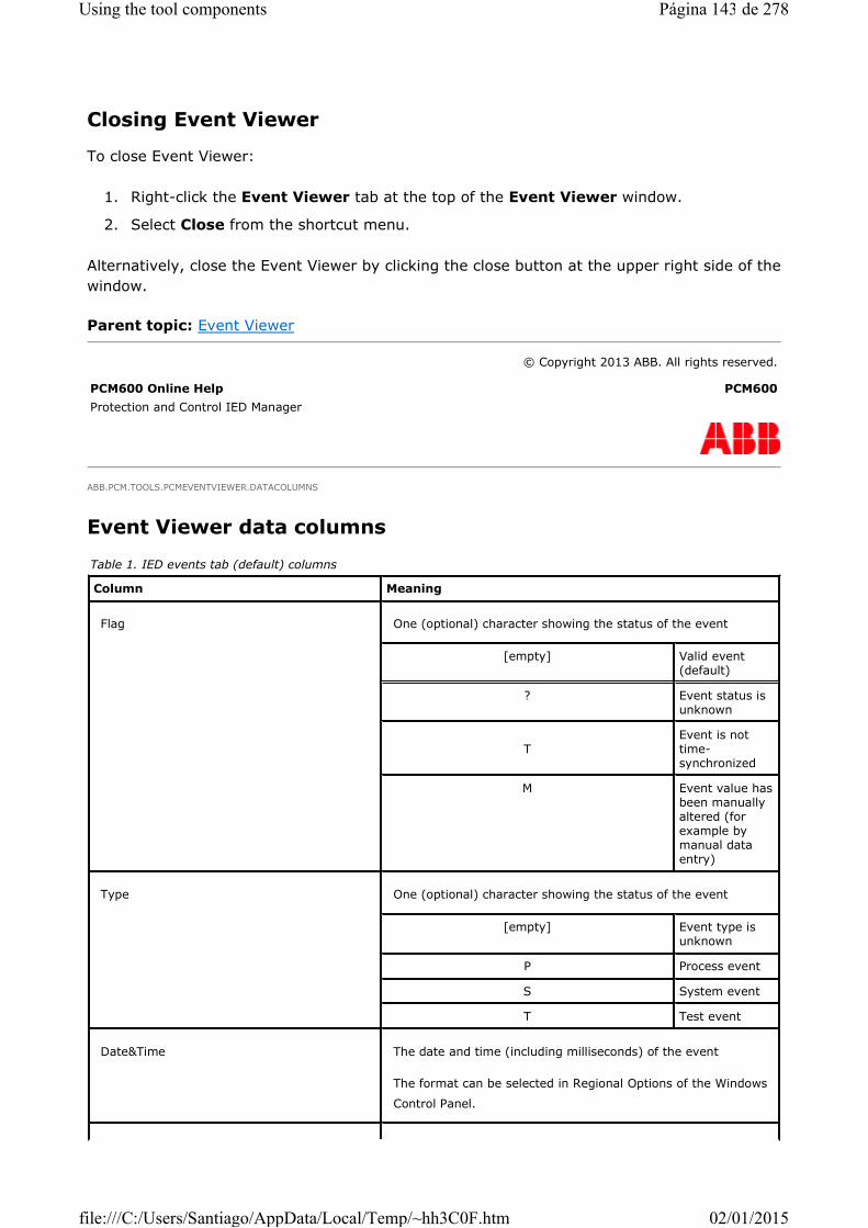
Closing Event Viewer
To close Event Viewer:
1. Right-click the Event Viewer tab at the top of the Event Viewer window.
2. Select Close from the shortcut menu.
Alternatively, close the Event Viewer by clicking the close button at the upper right side of the
window.
Parent topic: Event Viewer
ABB.PCM.TOOLS.PCMEVENTVIEWER.DATACOLUMNS
Event Viewer data columns
© Copyright 2013 ABB. All rights reserved.
PCM600 Online Help PCM600
Protection and Control IED Manager
Table 1. IED events tab (default) columns
Column Meaning
Flag One (optional) character showing the status of the event
[empty] Valid event(default)
? Event status is unknown
TEvent is nottime-synchronized
M Event value has been manually altered (forexample by manual data entry)
Type One (optional) character showing the status of the event
[empty] Event type isunknown
P Process event
S System event
T Test event
Date&Time The date and time (including milliseconds) of the event
The format can be selected in Regional Options of the Windows
Control Panel.
Página 143 de 278Using the tool components
02/01/2015file:///C:/Users/Santiago/AppData/Local/Temp/~hh3C0F.htm

Some of the columns can be hidden if all their values are empty.
Signal name The name of the signal that generated the event
Value The actual value of the signal at the time the event was
generated. The value displayed in this column is usually empty
for the binary signals. Their current value is displayed only in
the Status column. For analog signals, a numeric value
(integer or floating point) is usually displayed together with the
unit text. It can also be an empty value.
Status The text representation of the signal's status at the time the
event was generated.
Additional info An optional IED-specific (signal) information text (for example
function block name). It can be empty for some IED types.
Table 2. Security events tab columns
Column Meaning
Event Log ID Sequence number generated when a new incoming security event in the
persistency is saved.
Sequence Of Event Sequence number of the security events in the current transmission session
from sender to receiver.
Event Date Time Occurrence date and time at UTC of the security event in the originator.
Event Severity Severity of the security event
Unknown Severity not set or unknown.
Alarm Represents alarm.
Event Represents security event.
User Name User name of the user who caused the security events to occur.
Event ID The unique identifier for the security events
Event Text Description of the security event
Extra Information Additional information associated with the security events if any.
Source Security event source, name or identifier of the device or tool
Product Name Product name, type of the device or tool
IP Address IP address of the originating device or machine
Página 144 de 278Using the tool components
02/01/2015file:///C:/Users/Santiago/AppData/Local/Temp/~hh3C0F.htm

Parent topic: Event Viewer
ABB.PCM.TOOLS.PCMEVENTVIEWER.SORTING
Sorting event data
The default order of the events is by descending date and time, that is, the newest events are
shown at the top of the list.
To sort the event data differently, click the column header of the column to be sorted. The
data is sorted in ascending order of the column values which is indicated by an upwards
triangle on the right side of the column name. To sort in descending order, click the same
column header again. The descending order is indicated by a downwards triangle on the right
side of the column name. Clicking the same column header a third time the sort order
changes back to ascending.
The Date & Time column can also be sorted by selecting Event Viewer>Show newest
events on top/on bottom or by clicking the Show newest events on top/on bottom
toolbar button. If the event list is already sorted by date and time, the order is reversed by
the command.
The actual sort order is stored when closing Event Viewer and the same sort order is held
when Event Viewer is opened the next time.
Parent topic: Event Viewer
ABB.PCM.TOOLS.PCMEVENTVIEWER.FILTERING
Log Date Time Date and time in UTC when the event is stored in the persistency (central
log server or device).
Hierarchy Hierarchy to uniquely identify the device which produced the event.
Substation Substation name in which the source device is configured.
Voltage Level Voltage level name in which the source device is configured.
Bay Bay name in which the source device is configured.
© Copyright 2013 ABB. All rights reserved.
PCM600 Online Help PCM600
Protection and Control IED Manager
© Copyright 2013 ABB. All rights reserved.
PCM600 Online Help PCM600
Protection and Control IED Manager
Página 145 de 278Using the tool components
02/01/2015file:///C:/Users/Santiago/AppData/Local/Temp/~hh3C0F.htm

Filtering event data
Filtering allows reducing the amount of the displayed event data to a wanted subset.
To filter event data:
� Select Event Viewer>Filter On/Off or
� Click the Filter On/Off toolbar button.
A filter bar is displayed below the column headers consisting of a drop-down list box for each
column with the column values as menu items.
Select a value from the drop-down list box of the wanted column, to display only those
events, which have that specific value. To specify more detailed filter conditions, select
Custom filter. The Custom Filter for Event List Column dialog is displayed where detailed
conditions for example showing values inside a certain range; or combining two conditions
with an or-condition or an and-condition, can be specified. Click OK to apply the filtering
conditions.
Filters can be used on more than one column which causes the filter conditions to be
combined over these columns.
To turn off a filter condition on a specific column select No filter from the column's drop-
down list box.
To turn off all filters:
� Select Event Viewer>Filter On/Off again or
� Click the Filter On/Off toolbar button again.
The filter bar below the column headers disappears.
The actual filter settings are stored when closing Event Viewer and the same filter settings
are held when opening Event Viewer next time.
Parent topic: Event Viewer
ABB.PCM.TOOLS.PCMEVENTVIEWER.READEVENTS
Reading newest events from IED
To update the event data with the newest events from the IED:
� Select IED>Read newest events from IED or
© Copyright 2013 ABB. All rights reserved.
PCM600 Online Help PCM600
Protection and Control IED Manager
Página 146 de 278Using the tool components
02/01/2015file:///C:/Users/Santiago/AppData/Local/Temp/~hh3C0F.htm

� Click the Read newest events from IED toolbar button.
Note that depending on the capabilities of the IED and the corresponding
Connectivity Package new events are either automatically added to the tabular
display or collected and displayed by Event Viewer on a regular basis. The Read
newest events from IED command is therefore only useful if the waiting time
until the next automatic update seems to be too long. New events (if any) are
only added to the display if the actual time period is displayed, that is, the user
has not moved to a different time period (Refer to Moving to another period), and
if the new events match the actual filter settings (Refer to Filtering event data).
Parent topic: Event Viewer
ABB.PCM.TOOLS.PCMEVENTVIEWER.SELECTPERIOD
Selecting period type
Event Viewer displays event data only for a selected time period to reduce the amount of
displayed data which also improves performance, and to allow easier retrieval of needed
events. The default time period is one day. The event periods of defined hours work as evenly
distributed portions of a day. For example, periods for type 6 hours are from 00:00 to 06:00,
06:00 to 12:00, 12:00 to 18:00 and 18:00 to 24:00.
To select a period type:
� Select Event Viewer>Select period type and select the period type from the
submenu or
� Select the period type directly from the Select period type drop-down combo box.
Period type Unlimited allows displaying of all events for the IED irrespective of period length
boundaries. For all other period types, the period boundaries are lengthened by 5 minutes at
the beginning and at the end of the period to have the possibility to easily detect also the
events near the period boundaries. For example, if the actual selected period type is one day,
the events that happened shortly before or after midnight are displayed as well.
When selecting period types with a long period length, for example Unlimited,
Month or Week, loading events takes a considerable amount of time depending on
the number of events generated by the IED. In case an IED generates a lot of
events, it can be true also for period type Day or even shorter period types.
The actual period type is stored when closing Event Viewer and the same period type is held
© Copyright 2013 ABB. All rights reserved.
PCM600 Online Help PCM600
Protection and Control IED Manager
Página 147 de 278Using the tool components
02/01/2015file:///C:/Users/Santiago/AppData/Local/Temp/~hh3C0F.htm

when Event Viewer is opened the next time.
Parent topic: Event Viewer
ABB.PCM.TOOLS.PCMEVENTVIEWER.MOVETOPERIOD
Moving to another period
To move to the event data of another time period, select one of the following commands in
the Event Viewer menu or click one of the corresponding toolbar buttons:
� Go to first period
Moves to the oldest available event data of the IED.
� Go to previous period
� Go to next period
� Go to last period
Moves to the newest available event data of the IED.
� Go to specific period
Specify the date for which the events of the IED are to be displayed. In case the
selected period type is less than one day, the wanted hour can be selected as well. Exit
the dialog by clicking OK.
After selecting one of the commands, Event Viewer displays the events of the selected period.
These menu commands and toolbar buttons are enabled only if there is at least one event
whose date and time are outside the boundaries of the selected period. Furthermore, all
these commands and toolbar buttons are always disabled if period type Unlimited has been
selected.
When selecting period types with a long period length, for example Unlimited,
Month or Week, loading events takes a considerable amount of time depending on
the number of events generated by the IED. In case an IED generates a lot of
events, it can be true also for period type Day or even shorter period types.
Parent topic: Event Viewer
ABB.PCM.TOOLS.PCMEVENTVIEWER.CLEARIEDBUFFERS
© Copyright 2013 ABB. All rights reserved.
PCM600 Online Help PCM600
Protection and Control IED Manager
© Copyright 2013 ABB. All rights reserved.
PCM600 Online Help PCM600
Protection and Control IED Manager
Página 148 de 278Using the tool components
02/01/2015file:///C:/Users/Santiago/AppData/Local/Temp/~hh3C0F.htm
Clearing event buffers in IED
1. Clear all the internal event buffers of an IED.
� On the main menu, point to IED and then click Clear IED event buffer(s).
� On the toolbar, click the Clear IED event buffer(s) button.
2. To confirm the clearing, click Yes.
This command is enabled only if the IED and its corresponding connectivity package support
this feature, and the current user has access rights to clear the IED event buffers. To modify
the user management settings, see Modifying existing user category.
The command deletes all the events in the IED except for the already uploaded
events stored in the events datastore. To delete the events in the datastore, see
Deleting events in datastore.
Read the events before clearing the IED event buffer.
Parent topic: Event Viewer
ABB.PCM.TOOLS.PCMEVENTVIEWER.DELETEINDATASTORE
Deleting events in datastore
� Deleting the uploaded events from the IED that are stored in the Events datastore
� Select Event Viewer>Delete events in datastore or
� Click the Delete events in datastore toolbar button.
1. Confirm the deleting by clicking the Yes button.
2. Depending on the number of already uploaded events from the IED including the
events from earlier times using Event Viewer, deleting can take a considerable
amount of time. This command is only enabled if the current user has access
rights to delete events from Events Datastore. Refer to the user management
settings Modifying existing user category.
The command does not delete the events that are currently stored in the
internal event buffer(s) of the IED. Use Clearing event buffers in IED for this
purpose.
Parent topic: Event Viewer
© Copyright 2013 ABB. All rights reserved.
PCM600 Online Help PCM600
Protection and Control IED Manager
Página 149 de 278Using the tool components
02/01/2015file:///C:/Users/Santiago/AppData/Local/Temp/~hh3C0F.htm

GUID-2C90381E-64DB-404E-B3DA-350F7EFC5D10
Deleting all events before last read from IED
Deleting all events before last read from IED deletes all events which are already read
from the IED.
Stopping reading events from IED is supported based on the IED capability.
Parent topic: Event Viewer
GUID-9A8A3352-D0D2-4BAC-890C-3A7498F981B4
Stopping reading events from the IED
� In the Reading Events Status window, click Cancel. Event viewer shows the events
read before cancellation.
Stopping reading events from the IED is supported based on the IED capability.
Parent topic: Event Viewer
ABB.PCM.TOOLS.PCMEVENTVIEWER.PRINTING
Printing events
� Print the events that are currently displayed in Event Viewer in one of the alternative
ways.
� On the File menu, click Print.
� On the toolbar, click the Print button.
© Copyright 2013 ABB. All rights reserved.
PCM600 Online Help PCM600
Protection and Control IED Manager
© Copyright 2013 ABB. All rights reserved.
PCM600 Online Help PCM600
Protection and Control IED Manager
© Copyright 2013 ABB. All rights reserved.
PCM600 Online Help PCM600
Protection and Control IED Manager
Página 150 de 278Using the tool components
02/01/2015file:///C:/Users/Santiago/AppData/Local/Temp/~hh3C0F.htm

� Press CTRL+P.
In the Print dialog, select the wanted options and click OK.
� Before printing, examine the generated print document in one of the alternative ways.
� On the File menu, click Print Preview.
� On the toolbar, click the Print Preview button.
� Press CTRL+SHIFT+P.
� Use the Zoom function to check how many pages there are and how the pages are
printed. Click OK to print.
� In the Print Options window, select the columns to print or print preview by clicking
Print or Print Preview.
The Print Options window appears when Event Viewer contains both the IED events
and the Security events tab.
The Print and Print Preview functions are disabled if no events are currently shown in
the Event Viewer display or if the default printer is not defined.
Parent topic: Event Viewer
GUID-83918E43-04BD-4C20-95CD-7C18A478F80B
Exporting events to other programs
1. Copy the currently displayed events in Event Viewer to the clipboard in one of the
alternative ways.
� On the Edit menu, click Copy.
� On the toolbar, click the Copy button.
� Press CTRL+C.
2. Add the events to another program, for example to Microsoft Excel or Microsoft Word.
� Alternatively, export the currently displayed events in Event Viewer directly to
Microsoft Excel.
1. Select Reports>Export To Excel File.
2. On the toolbar, click the Export To Excel File button.
3. Save the Excel file that contains the exported events. The exported file is
automatically opened, if the computer can open the XLS files.
All exporting functions are disabled, if no events are currently displayed in the Event
Viewer tabular display.
© Copyright 2013 ABB. All rights reserved.
PCM600 Online Help PCM600
Protection and Control IED Manager
2.1 Start the program.
2.2 Open an existing document by selecting File>Open to add the events to it, or create a new document by selecting File>New.
2.3 Select Edit>Paste or click the Paste button on the toolbar.
Página 151 de 278Using the tool components
02/01/2015file:///C:/Users/Santiago/AppData/Local/Temp/~hh3C0F.htm
Security events are exported to XLSX file format.
Parent topic: Event Viewer
ABB.PCM.TOOLS.PCMEVENTVIEWER.OPTIONS
Viewing Event Viewer options
� Start Event Viewer and, on the menu bar, click Options, or on the toolbar, click Opt.
There are various options available in the Event Viewer - Options dialog box.
� Select Show actual IED events only or Show historic and actual IED
events to see the default value. The historic events are read from the IED and
they are not stored in the IED event buffers.
� Set the time for reading from the IED with the drop-down list in the Interval
used for reading new events from IED field. The number of seconds is
relevant only for the IEDs which have the type of IED Connectivity Package that
does not support a spontaneous notification about new events in the IED. This
can be set to None if it is not required to read from the IED.
� Set the current setting of sort options, column filter settings, period type and
reading interval to differently per substation, differently per voltage level,
differently per bay, differently per IED type or differently for each IED.
The setting is identically for all IEDs by default.
Two polling interval sections are shown to set the interval for the IED events and
security events if the IED supports security events. The security events date time
stamps are shown based on the selection between Coordinated Universal Time
(UTC) or Local time.
The default value for the Interval used for reading new events from IED
field is 30 seconds. The setting depends on the IED capability and can be
changed and saved.
Parent topic: Event Viewer
ABB.PCM.TOOLS.PCMDISPLAYEDITOR.ABOUTGDE
Graphical Display Editor
© Copyright 2013 ABB. All rights reserved.
PCM600 Online Help PCM600
Protection and Control IED Manager
© Copyright 2013 ABB. All rights reserved.
PCM600 Online Help PCM600
Protection and Control IED Manager
Página 152 de 278Using the tool components
02/01/2015file:///C:/Users/Santiago/AppData/Local/Temp/~hh3C0F.htm

Graphical Display Editor is a tool for configuring the graphical display of an IED, also called
Local Human-Machine Interface (LHMI).
The graphical display consists of one or more display pages. A display page contains the
drawing area where the actual graphical configuration is made.
A display is configured by dragging preconfigured symbols from a library onto the drawing
area. The link tool can be used to draw connections between symbols.
Symbol palettes
A symbol palette contains all the symbols supported by Graphical Display Editor.
The IEC symbol palette and ANSI symbol palette are the two symbol palettes supported. The
symbol palette set in Tools>Options>System Settings>Symbol Standards is the default
symbol palette of the IED. The ANSI symbol palette is mainly intended to be used in the U.S.
market.
Every symbol type has a corresponding representation in both the ANSI and the IEC symbol
palettes.
Switch symbols
The status and the position of all the switch symbols are dynamically updated on the LHMI.
The indication only switches, however, are not controllable.
Dynamic Text
The dynamic texts have two parts, label text and state text. The label text is static and the
state text is the dynamic value of a connected signal. The label text can be edited by double
clicking the symbol or by modifying the Name field in the Object properties window. The
starting point of the state text is represented using the # symbol. The LHMI in the IED shows
the value of the connected signal from the starting point of the state text location in
Graphical Display Editor. The location of the state text can be changed in the Alignment
value field in the Object properties window. The alignment value is the distance from the
starting point of the label text to the starting point of the state text in LHMI pixels.
If a value less than the sum of label text width and minimum gap is entered, the
alignment value changes to the sum of the label text width and minimum gap by
default. The minimum gap is 10 pixels.
Starting Graphical Display Editor
Closing Graphical Display Editor
Graphical Display Editor toolbar
Reading display information from the IED
Creating display pages
Printing display pages
Saving the display configuration
Writing display information to the IED
Template export and import
Página 153 de 278Using the tool components
02/01/2015file:///C:/Users/Santiago/AppData/Local/Temp/~hh3C0F.htm

Parent topic: Using the tool components
ABB.PCM.TOOLS.PCMDISPLAYEDITOR.STARTINGGDE
Starting Graphical Display Editor
1. Right-click IED in the object tree.
2. Select Graphical Display Editor from the shortcut menu.
Alternatively, start Graphical Display Editor by selecting Tools>Graphical Display Editor.
Parent topic: Graphical Display Editor
ABB.PCM.TOOLS.PCMDISPLAYEDITOR.CLOSINGGDE
Closing Graphical Display Editor
1. Right-click the Graphical Display Editor tab above the Symbol Library.
2. Select Close from the shortcut menu.
Alternatively, close the Graphical Display Editor by clicking the close button at the upper
right side of the window.
When the tool is closed without saving the changes, the user is given the option to save the
changes or quit.
Parent topic: Graphical Display Editor
ABB.PCM.TOOLS.PCMDISPLAYEDITOR.TOOLBAR
Graphical Display Editor toolbar
© Copyright 2013 ABB. All rights reserved.
PCM600 Online Help PCM600
Protection and Control IED Manager
© Copyright 2013 ABB. All rights reserved.
PCM600 Online Help PCM600
Protection and Control IED Manager
© Copyright 2013 ABB. All rights reserved.
PCM600 Online Help PCM600
Protection and Control IED Manager
Toolbar button Function
Página 154 de 278Using the tool components
02/01/2015file:///C:/Users/Santiago/AppData/Local/Temp/~hh3C0F.htm

Parent topic: Graphical Display Editor
ABB.PCM.TOOLS.PCMDISPLAYEDITOR.UPLOADING
Reading display information from the IED
� On the IED menu, click Read Display Configuration from IED.
� Click the Read Display Configuration from IED toolbar button.
It is required to confirm this action before it is carried out because the action overwrites the
existing display configuration of Graphical Display Editor. The reading operation can take a
few seconds or minutes to complete.
If the user belongs to a user category which is authorized to access the IED online, the read
function can be used.
Configuration is automatically saved after reading a display configuration from the
Read display configuration from the IED.
Write the display configuration from the Graphical Display Editor to the
IED.
Add display page.
Remove display page.
The Select function selects and moves symbols.
The Pan function moves the display page.
The Show Grid function displays or hides the grid in the display page.
With Snap to Grid function enabled, a symbol is positioned with its top
left corner at the intersection of the nearest grid lines.
The Zoom function zooms in and out of the current diagram.
The Rotate Left function rotates a symbol 90 degrees to the left.
The Rotate Right function rotates a symbol 90 degrees to the right.
© Copyright 2013 ABB. All rights reserved.
PCM600 Online Help PCM600
Protection and Control IED Manager
Página 155 de 278Using the tool components
02/01/2015file:///C:/Users/Santiago/AppData/Local/Temp/~hh3C0F.htm

IED.
Parent topic: Graphical Display Editor
ABB.PCM.TOOLS.PCMDISPLAYEDITOR.USINGGDE
Creating display pages
Start Graphical Display Editor as described in Starting Graphical Display Editor.
If the user belongs to a user category, which has the read/write access to the Graphical
Display Editor configuration, the graphical display configuration can be modified. See
Modifying existing user category.
If a display configuration is already available in the IED, it is possible to read the configuration
from the IED. See Reading display information from IED.
If the user belongs to a user category, which is authorized to access the IED online, the read
function can be used.
Adding display pages
Removing display pages
Creating single-line diagrams
Selecting input signals for dynamic symbols
Selecting symbols and links
Moving symbols
Modifying symbol properties
Deleting, cutting, copying and pasting
Undoing and redoing
Panning and zooming
Changing display page order
Parent topic: Graphical Display Editor
ABB.PCM.TOOLS.PCMDISPLAYEDITOR.ADDPAGESANDCONTAINERS
Adding display pages
© Copyright 2013 ABB. All rights reserved.
PCM600 Online Help PCM600
Protection and Control IED Manager
© Copyright 2013 ABB. All rights reserved.
PCM600 Online Help PCM600
Protection and Control IED Manager
Página 156 de 278Using the tool components
02/01/2015file:///C:/Users/Santiago/AppData/Local/Temp/~hh3C0F.htm

� Select Graphical Display Editor >Add Display Page or
� Click the Add Display Page toolbar button.
A new tab with the name of the new display page is visible in Graphical Display Editor. The
maximum number of display pages are 12.
Parent topic: Creating display pages
ABB.PCM.TOOLS.PCMDISPLAYEDITOR.REMOVEPAGESANDCONTAINERS
Removing display pages
� Select Graphical Display Editor>Remove Display Page or
� Click the Remove Display Page toolbar button
When removing a display page, the content is also removed. It is not possible to undo a
display page removal. Therefore, the action is required to confirm before it is carried out.
Parent topic: Creating display pages
ABB.PCM.TOOLS.PCMDISPLAYEDITOR.CREATESLD
Creating single-line diagrams
1. Optionally add more display pages as described in Adding display pages.
2. Select the wanted symbol library (IEC or ANSI) from the combo box at the top of the
Graphical Display Editor.
3. Ensure that the Snap to grid and Show grid functions are available.
This is the default and recommended setting when designing a single-line diagram.
� Enable and disable these functions using the Snap to Grid and Show Grid
buttons.
� Select corresponding menu items from the Graphical Display Editor menu.
4. Place the primary equipment on the single-line diagram in the wanted position
approximately.
� If required, rotate the symbols using the Rotate Left or Rotate Right functions.
� If many symbols have to be inserted in a diagram, select a smaller symbol size
© Copyright 2013 ABB. All rights reserved.
PCM600 Online Help PCM600
Protection and Control IED Manager
© Copyright 2013 ABB. All rights reserved.
PCM600 Online Help PCM600
Protection and Control IED Manager
Página 157 de 278Using the tool components
02/01/2015file:///C:/Users/Santiago/AppData/Local/Temp/~hh3C0F.htm

from the drop-down menu.
5. Consider the necessary symbol connections (links).
Wherever a connection needs to be made at a right angle, a Junction symbol should be
placed on the diagram. For example, a Junction symbol (from the Connections palette)
should be placed at the "T" intersection between the two busbar isolators and the
circuit breaker in a typical double busbar feeder diagram.
6. Connect the symbols where necessary.
It is not necessary to connect electrically all the symbols using the Link tool.
If a symbol already appears to be connected, it is not necessary to create a
link explicitly.
a. Move the mouse pointer over the symbol's connection point. The connection of all
the signals are activated.
b. Drag the connection from the source connection port and drop it in the target
connection port. A connection line between the source and target connection
ports is drawn.
Once a link has been used to connect the symbols, the link follows the symbol when it
is moved to a new position or when it is rotated. See Moving symbols.
7. After creating the connections, move the mouse pointer away from the symbol's
connection point for all the connection ports of the symbols to become deactivated.
8. Select a symbol and modify its properties in the Object Properties window. See
Modifying symbol properties. The symbol name can also be changed by double-clicking
the symbol.
9. Relate dynamic symbols to their source data as described in Selecting input signals for
dynamic symbols.
10. Configure the tab order of controllable objects. The tab order defines the order in which
the controllable objects are selected when the Select button is pressed on the IED.
� The tab order is set using the Tab order property. The first symbol to be selected
should be set with a Tab order of 1 in the Object Properties window.
� The Sort Tab Order function from the Graphical Display Editor menu can also
be used.
In general, all the lines pass through the middle of a grid square and the symbols
fill the entire grid square.
Parent topic: Creating display pages
ABB.PCM.TOOLS.PCMDISPLAYEDITOR.CONNECTINGDYNAMICSYMBOLS
© Copyright 2013 ABB. All rights reserved.
PCM600 Online Help PCM600
Protection and Control IED Manager
Página 158 de 278Using the tool components
02/01/2015file:///C:/Users/Santiago/AppData/Local/Temp/~hh3C0F.htm

Selecting input signals for dynamic symbols
Relate the dynamic symbols to their input signals by right-clicking the symbol and choosing
the Select input signal from the shortcut menu. A drop-down menu containing a list of
appropriate signals for this symbol is displayed. The Input Signal property in the Object
properties window is updated to reflect the new configuration. Alternatively, the input signal
can be selected directly in the drop-down menu on the right to the Input Signal property.
An input signal can be chosen for several symbols. If the same input signal is also related to
other symbols, the input signal name is marked by an asterisk in the drop-down menu. The
signal names are shown only if there is more than one connectable signal for a function block,
else, only the function block name is shown.
Parent topic: Creating display pages
ABB.PCM.TOOLS.PCMDISPLAYEDITOR.SELECTING
Selecting symbols and links
1. Activate the Select tool.
� Click the Select toolbar button.
� Select Graphical Display Editor >Select.
2. Click a symbol or a link. The selection turns grey.
To select all symbols and links on the actual display page:
� Select Edit>Select All or
� Press CTRL + A
To select multiple symbols and links, press CTRL while selecting symbols or links.
To select multiple neighboring symbols and links, draw a rectangle by pressing
the mouse button and moving the mouse. All the symbols and links are selected
that are located in the rectangular area.
Parent topic: Creating display pages
© Copyright 2013 ABB. All rights reserved.
PCM600 Online Help PCM600
Protection and Control IED Manager
© Copyright 2013 ABB. All rights reserved.
PCM600 Online Help PCM600
Protection and Control IED Manager
Página 159 de 278Using the tool components
02/01/2015file:///C:/Users/Santiago/AppData/Local/Temp/~hh3C0F.htm

ABB.PCM.TOOLS.PCMDISPLAYEDITOR.MOVINGSYMBOLS
Moving symbols
1. Select a symbol to be moved. See Selecting symbols and links.
2. Drag the symbol to the wanted position.
The symbols must remain completely within the boundaries of the display page. If a symbol is
dragged to a position beyond the boundaries of the display page, it is automatically returned
to the last allowed position in the diagram when the mouse button is released. The existing
links are also moved with their connected symbols. The symbols are auto aligned, so if a
symbol is placed on another symbol, it is placed to the nearest available location.
The junction symbol can be placed on other symbols.
Parent topic: Creating display pages
ABB.PCM.TOOLS.PCMDISPLAYEDITOR.PROPERTIES
Modifying symbol properties
The Object Properties window opens when the Graphical Display Editor is started.
When clicking a symbol on the display page, its properties are shown in the Object
Properties window. The symbol properties can vary depending on the selected object. The
Name property can be changed by double-clicking the symbol and entering a new name. The
text font can also be chosen from the drop-down menu above the diagram.
When clicking on an empty location on the diagram, or when multiple symbols or links are
selected, the properties of the display page are shown in the Object Properties window. The
name of the display page can be changed here.
Parent topic: Creating display pages
ABB.PCM.TOOLS.PCMDISPLAYEDITOR.DELETECOPYPASTE
© Copyright 2013 ABB. All rights reserved.
PCM600 Online Help PCM600
Protection and Control IED Manager
© Copyright 2013 ABB. All rights reserved.
PCM600 Online Help PCM600
Protection and Control IED Manager
Página 160 de 278Using the tool components
02/01/2015file:///C:/Users/Santiago/AppData/Local/Temp/~hh3C0F.htm
Deleting, cutting, copying and pasting
Use the Delete command to delete the selected symbols and links:
� Select Edit>Delete or
� Press DELETE or
� Right-click and choose Delete.
Use the Cut command to delete the selected symbols and links and move them to the
clipboard:
� Select Edit>Cut or
� Click the Cut toolbar button or
� Press CTRL+X or
� Right-click and choose Cut.
Use the Copy command to copy the selected symbols and links to the clipboard:
� Select Edit>Copy or
� Click the Copy toolbar button or
� Press CTRL+C or
� Right-click and choose Copy.
Use the Paste command to paste the earlier cut or copied symbols and links from the
clipboard:
� Select Edit>Paste or
� Click the Paste toolbar button or
� Press CTRL+V or
� Right-click and choose Paste.
Different display pages can be pasted across same type of IEDs.
Parent topic: Creating display pages
ABB.PCM.TOOLS.PCMDISPLAYEDITOR.UNDOREDO
Undoing and redoing
To undo the last action:
� Select Edit>Undo or
© Copyright 2013 ABB. All rights reserved.
PCM600 Online Help PCM600
Protection and Control IED Manager
Página 161 de 278Using the tool components
02/01/2015file:///C:/Users/Santiago/AppData/Local/Temp/~hh3C0F.htm
� Click the Undo toolbar button or
� Right-click and choose Undo.
To redo the last action:
� Select Edit>Redo or
� Click the Redo toolbar button
� Right-click and choose Redo.
Parent topic: Creating display pages
ABB.PCM.TOOLS.PCMDISPLAYEDITOR.PANZOOM
Panning and zooming
To zoom in and out of the current display page:
� Select Graphical Display Editor>Zoom or
� Click the Zoom toolbar button or
� Right-click and choose Zoom.
To move the current display page:
1. Select Graphical Display Editor>Pan or click the Pan toolbar button.
When the Pan tool is activated, the pointer changes to a hand when the mouse is
moved over the current display page.
2. Click and drag the display page using the left mouse button.
To move the current display page back to its original position, double-click the page while the
Pan tool is active.
To deactivate the Pan tool:
� Click the Pan button again or
� Click the Select button or
� Press ESC.
Parent topic: Creating display pages
© Copyright 2013 ABB. All rights reserved.
PCM600 Online Help PCM600
Protection and Control IED Manager
© Copyright 2013 ABB. All rights reserved.
PCM600 Online Help PCM600
Protection and Control IED Manager
Página 162 de 278Using the tool components
02/01/2015file:///C:/Users/Santiago/AppData/Local/Temp/~hh3C0F.htm

ABB.PCM.TOOLS.PCMDISPLAYEDITOR.CHANGEORDER
Changing display page order
1. Click the display page header.
2. Drag the display page to the required location.
The display page order in the IED changes depending on the IED capability.
Parent topic: Creating display pages
ABB.PCM.TOOLS.PCMDISPLAYEDITOR.PRINTING
Printing display pages
1. Preview the generated document before printing it.
� Select File>Print Preview.
� Click the Print Preview toolbar button.
� Press CTRL+SHIFT+P.
� Right-click and choose Print Preview.
2. Open the Print dialog box.
� Select File>Print.
� Click the Print toolbar button.
� Press CTRL+P.
� Right-click and choose Print.
A Print dialog appears.
3. Select the required print options and click OK.
Parent topic: Graphical Display Editor
ABB.PCM.TOOLS.PCMDISPLAYEDITOR.SAVINGGDE
Saving the display configuration
© Copyright 2013 ABB. All rights reserved.
PCM600 Online Help PCM600
Protection and Control IED Manager
© Copyright 2013 ABB. All rights reserved.
PCM600 Online Help PCM600
Protection and Control IED Manager
Página 163 de 278Using the tool components
02/01/2015file:///C:/Users/Santiago/AppData/Local/Temp/~hh3C0F.htm

� Select File>Save or
� Click the Save toolbar button or
� Press CTRL+S or
� Right-click and choose Save.
Parent topic: Graphical Display Editor
ABB.PCM.TOOLS.PCMDISPLAYEDITOR.DOWNLOADING
Writing display information to the IED
� Select IED>Write Display Configuration to IED or
� Click the Write Display Configuration to IED toolbar button.
It is required to confirm this action before it is carried out, because the action overwrites the
existing display configuration of the IED. The writing operation can take a few seconds or
minutes to complete.
Parent topic: Graphical Display Editor
ABB.PCM.TOOLS.PCMDISPLAYEDITOR.TEMPLATES
Template export and import
The single-line diagram templates enable the reuse of the single-line diagram created in the
Graphical Display Editor tool. The single-line diagram can be exported as a template and
the same template can be imported to another IED. The file extension of the single-line
diagram template file is .psld.
Exporting a template
Importing a template
Parent topic: Graphical Display Editor
© Copyright 2013 ABB. All rights reserved.
PCM600 Online Help PCM600
Protection and Control IED Manager
© Copyright 2013 ABB. All rights reserved.
PCM600 Online Help PCM600
Protection and Control IED Manager
© Copyright 2013 ABB. All rights reserved.
PCM600 Online Help PCM600
Protection and Control IED Manager
Página 164 de 278Using the tool components
02/01/2015file:///C:/Users/Santiago/AppData/Local/Temp/~hh3C0F.htm

ABB.PCM.TOOLS.PCMDISPLAYEDITOR.TEMPLATESEXPORT
Exporting a template
1. Create a single-line diagram in the Graphical Display Editor tool.
2. On the menu bar, point to Graphical Display Editor and select Export Single Line
Diagram as a Template. The Single Line Diagram Export window appears with two
sections. All the available display pages are listed in a tree view in the Preview panel
section.
3. Select the check box to select the display pages in the tree view. The preview of the
single-line diagram present in the selected display page is displayed in the Preview
panel section.
4. Once the display page is selected, click Export. The File save dialog box appears.
5. Browse the location to export the template and provide the file name. The default file
name is the bay name+date.
By default, single-line diagram templates are saved in the drive where PCM600 is
installed <Drive:> \PCMDataBases\GDE\Templates\<IED type folder>.
Parent topic: Template export and import
ABB.PCM.TOOLS.PCMDISPLAYEDITOR.TEMPLATESIMPORT
Importing a template
1. On the menu bar, point to Graphical Display Editor and select Import Single Line
Diagram Template. The Single Line Diagram Import window appears with two
sections, List of Templates and Display Pages Preview.
2. Click Browse to select the template files. The templates available in the folder appear
in the List of Templates section.
3. Select a template file to preview the display pages available in the template file.
4. Double-click the display page preview to enlarge it. The display pages can be selected
from the preview.
5. Once the display pages are selected, click Import to import the display page.
Multiple pages can be selected for the Import function.
© Copyright 2013 ABB. All rights reserved.
PCM600 Online Help PCM600
Protection and Control IED Manager
Página 165 de 278Using the tool components
02/01/2015file:///C:/Users/Santiago/AppData/Local/Temp/~hh3C0F.htm
Parent topic: Template export and import
ABB.PCMTOOLS.HARDWARECONFIGURATION
Hardware Configuration
The Hardware Configuration tool is used to configure the IED's hardware modules and to
troubleshoot the IED's hardware configuration.
Starting hardware configuration
Closing hardware configuration
Changing hardware modules
Changing display type
Changing housing type
Changing hardware parameters
Saving hardware configuration
Reading hardware configuration from IED
Writing hardware configuration to IED
Comparing hardware configuration
Printing hardware configuration
Parent topic: Using the tool components
ABB.PCMTOOLS.HARDWARECONFIGURATION.STARTTOOL
Starting hardware configuration
To start the Hardware Configuration tool:
1. Right-click an IED in the object tree
2. Select
� Hardware Configuration from the shortcut menu or
� Tools>Hardware Configuration.
You can start the tool on different levels in the object tree:
1. Expand an IED node.
© Copyright 2013 ABB. All rights reserved.
PCM600 Online Help PCM600
Protection and Control IED Manager
© Copyright 2013 ABB. All rights reserved.
PCM600 Online Help PCM600
Protection and Control IED Manager
Página 166 de 278Using the tool components
02/01/2015file:///C:/Users/Santiago/AppData/Local/Temp/~hh3C0F.htm
2. Right-click
� IED configuration node or
� hardware configuration node.
Parent topic: Hardware Configuration
ABB.PCMTOOLS.HARDWARECONFIGURATION.CLOSETOOL
Closing hardware configuration
To close the Hardware Configuration tool:
1. Right-click the Hardware Configuration tab at the top of the Hardware
Configuration window.
2. Select Close from the shortcut menu.
Alternatively, close the Hardware Configuration by clicking the close button at the upper
right side of the window.
If you try to close the tool before saving the changes, the program asks whether you want to
save the changes.
Parent topic: Hardware Configuration
ABB.PCMTOOLS.HARDWARECONFIGURATION.CHANGEHW
Changing hardware modules
The optional hardware modules can be replaced with other supported hardware modules in
the slot. A new hardware module can also be created using the supported hardware modules.
If the slot type is fixed or mandatory for some hardware modules, the slot cannot
be empty. The hardware modules should be created contiguously if the device
variant does not support empty slots between them.
The fixed or mandatory slots are highlighted in turquoise color. The optional slots
© Copyright 2013 ABB. All rights reserved.
PCM600 Online Help PCM600
Protection and Control IED Manager
© Copyright 2013 ABB. All rights reserved.
PCM600 Online Help PCM600
Protection and Control IED Manager
Página 167 de 278Using the tool components
02/01/2015file:///C:/Users/Santiago/AppData/Local/Temp/~hh3C0F.htm
are shown as normal rows.
For hardware configuration information, the below features are only applicable to
connectivity packages supporting dynamic rear-view images.
1. On the Hardware Configuration, click the Card Type drop-down list.
2. Select a hardware module.
� The respective hardware card module image is updated in the rear view
� Changing the hardware modules of the grid changes the hardware module card
images in the rear view.
� Each card is updated with its respective hardware module card image in the rear
view.
� A blank hardware module card image is shown only if the slot is empty or if there
is no card in the hardware configuration grid.
.
Parent topic: Hardware Configuration
ABB.PCMTOOLS.HARDWARECONFIGURATION.CHANGELHMI
Changing display type
To change the display type, select Display type from the drop-down menu and choose the
required type.
The display type is disabled, if it is not allowed to change the LHMI display to a
particular IED.
Parent topic: Hardware Configuration
ABB.PCM.TOOLS.HWT
Changing housing type
1. Select the required housing type from the Housing drop-down list. The rear view image
© Copyright 2013 ABB. All rights reserved.
PCM600 Online Help PCM600
Protection and Control IED Manager
© Copyright 2013 ABB. All rights reserved.
PCM600 Online Help PCM600
Protection and Control IED Manager
Página 168 de 278Using the tool components
02/01/2015file:///C:/Users/Santiago/AppData/Local/Temp/~hh3C0F.htm

is changed and the supporting hardware modules are updated in the grid based on the
housing type.
2. Save the changes to the housing type. If the changes are not saved, the previous
housing and hardware configuration are restored.
If the slots are not compatible between the old and the new housing type,
the modules in these slots are highlighted with wheat color in the hardware
configuration grid, and a message is displayed asking to select a supported
hardware module for the replacement in the grid.
Save the hardware module changes before changing the housing type.
� If any hardware modules are added or removed after changing the Housing,
those modules are respectively added or deleted from the hardware configuration
grid.
If multiple housing types are not supported for an IED, the Housing drop-
down list is disabled.
Parent topic: Hardware Configuration
ABB.PCMTOOLS.HARDWARECONFIGURATION.CHANGEHWPARAMETER
Changing hardware parameters
To change hardware module parameters:
1. Right-click on a card space row on the hardware configuration grid view.
2. Select Parameter Settings from the shortcut menu to open the Parameter Settings
tool. The tool shows the parameters of the selected hardware module.
3. Make the changes and save.
4. Close the Parameter Setting tool.
An alternative way to change the hardware module parameters:
1. Select IED>Parameter Settings.
2. Right-click on a hardware module under HW Configuration in the plant structure.
3. Select Parameter Settings from the shortcut menu.
Parent topic: Hardware Configuration
© Copyright 2013 ABB. All rights reserved.
PCM600 Online Help PCM600
Protection and Control IED Manager
Página 169 de 278Using the tool components
02/01/2015file:///C:/Users/Santiago/AppData/Local/Temp/~hh3C0F.htm
ABB.PCMTOOLS.HARDWARECONFIGURATION.SAVE
Saving hardware configuration
To save the hardware configuration:
� Select File>Save or
� Click the Save button in the toolbar.
Parent topic: Hardware Configuration
ABB.PCMTOOLS.HARDWARECONFIGURATION.READ
Reading hardware configuration from IED
The hardware configuration can be read from the connected IED. The PCM600 configuration is
replaced with the IED configuration if the reading is completed successfully.
1. Right-click the specific IED object in the plant structure.
2. Select Read from IED. A confirmation message is displayed.
3. Select Yes to confirm.
It is required to confirm an action before it is carried out, because the action overwrites the
existing PCM600 configuration. A message is shown if a invalid configuration is found.
Parent topic: Hardware Configuration
ABB.PCMTOOLS.HARDWARECONFIGURATION.WRITE
Writing hardware configuration to IED
A PCM600 configuration can be written to the IED if the connected IED supports the writing
process.
© Copyright 2013 ABB. All rights reserved.
PCM600 Online Help PCM600
Protection and Control IED Manager
© Copyright 2013 ABB. All rights reserved.
PCM600 Online Help PCM600
Protection and Control IED Manager
© Copyright 2013 ABB. All rights reserved.
PCM600 Online Help PCM600
Protection and Control IED Manager
Página 170 de 278Using the tool components
02/01/2015file:///C:/Users/Santiago/AppData/Local/Temp/~hh3C0F.htm

1. Right-click the specific IED object in the plant structure and select Write to IED. A
confirmation message is displayed.
2. Select Yes to confirm.
It is required to confirm an action before it is carried out, because the action overwrites the
entire IED configuration.
Parent topic: Hardware Configuration
ABB.PCMTOOLS.HARDWARECONFIGURATION.COMPARE
Comparing hardware configuration
The hardware configurations created using PCM600 and the IED can be compared. After
comparison, the differences between the configurations are shown.
To compare hardware configuration:
� Click the Compare Configuration button in the toolbar.
� Select IED>Compare Configuration from the PCM600 main menu.
The report is shown if PCM600 and the IED housing variants match.
Parent topic: Hardware Configuration
ABB.PCMTOOLS.HARDWARECONFIGURATION.PRINT
Printing hardware configuration
1. Start the Hardware Configuration tool.
2. Click the Print preview button on the tool bar, or on the File menu, select Print
Configuration.
3. Click the Save button on the toolbar.
The hardware configuration is stored as a PDF file by default.
Parent topic: Hardware Configuration
© Copyright 2013 ABB. All rights reserved.
PCM600 Online Help PCM600
Protection and Control IED Manager
© Copyright 2013 ABB. All rights reserved.
PCM600 Online Help PCM600
Protection and Control IED Manager
Página 171 de 278Using the tool components
02/01/2015file:///C:/Users/Santiago/AppData/Local/Temp/~hh3C0F.htm

ABB.PCM.TOOLS.ICE
IEC 61850 Configuration
The IEC 61850 Configuration tool is used for GOOSE, client-server and process bus data flow
engineering between IEDs in a substation.
In the GOOSE mode, data sets, GOOSE control blocks and inputs of IEDs are configured. In
the client server mode, data sets and report control blocks of IEDs are configured. In the
process bus mode, data sets, sampled value control blocks and inputs of IEDs are configured.
The data displayed in the IEC 61850 Configuration tool is context-sensitive with the current
selection in PCM600 Plant Structure. That is, only the data of the IEDs residing under the
selected Plant Structure tree node is displayed.
The IEC 61850 Configuration tool window consists of a matrix which has the receiver access
points as columns on the top and data available for receiving as rows on the left. The grey
arrow on the upper-left corner of the tool window depicts the data flow direction. Each data
row in the matrix contains a check box for each receiver access point to know that the data is
sent to or received by the access point in the corresponding column.
On top of the tool window is a drop-down list for selecting the configuration mode, that is,
which part of the IEC 61850 configuration to configure.
Next to the drop-down list are buttons for selecting the tool mode, IED naming convention
and two context-sensitive buttons for creating new objects or viewing or editing details of the
currently selected object.
At the bottom of the tool window are tab pages for selecting the type of data to configure.
The available type of data depends on the selected configuration mode.
The properties of the data currently selected in the matrix are displayed on the right in the
Object Properties window. In this window, it is possible to edit the object’s properties.
Data Sets tab
GOOSE Controls tab
Inputs tab
Report Controls tab
Sampled Value Controls tab
Starting IEC 61850 Configuration
Changing the configuration mode
Changing configuration data type
Switching IEC 61850 IED naming on and off
Switching engineering mode on and off
Sending and receiving data
© Copyright 2013 ABB. All rights reserved.
PCM600 Online Help PCM600
Protection and Control IED Manager
Página 172 de 278Using the tool components
02/01/2015file:///C:/Users/Santiago/AppData/Local/Temp/~hh3C0F.htm
Creating new objects
Copying objects
Cutting objects
Pasting objects
Deleting objects
Editing data set entries
Changing the order of report clients
Changing control block data sets
Editing object properties
Printing
Saving changes
Importing client ICD files
Parent topic: Using the tool components
ABB.PCM.TOOLS.ICE.DATASETS
Data Sets tab
Several functions are possible in the Data Sets tab.
� Configuring, sending and receiving data sets.
� Editing data set entries.
� Editing data set properties.
� Copying/cutting/pasting/deleting data sets.
Parent topic: IEC 61850 Configuration
ABB.PCM.TOOLS.ICE.GOOSECONTROLS
GOOSE Controls tab
Several functions are possible in the GOOSE Controls tab.
� Configuring, sending and receiving of GOOSE control blocks.
� Editing GOOSE control block properties.
� Changing the connected data set.
© Copyright 2013 ABB. All rights reserved.
PCM600 Online Help PCM600
Protection and Control IED Manager
© Copyright 2013 ABB. All rights reserved.
PCM600 Online Help PCM600
Protection and Control IED Manager
Página 173 de 278Using the tool components
02/01/2015file:///C:/Users/Santiago/AppData/Local/Temp/~hh3C0F.htm
� Copying/cutting/pasting/deleting GOOSE control blocks.
The GOOSE Controls tab page is available only in the GOOSE communication
mode.
Parent topic: IEC 61850 Configuration
ABB.PCM.TOOLS.ICE.GOOSEINPUTS
Inputs tab
Two functions are possible in the Inputs tab.
� Editing input properties.
� Deleting inputs.
The Inputs tab is available only in the GOOSE and Process Bus communication
modes.
Parent topic: IEC 61850 Configuration
ABB.PCM.TOOLS.ICE.REPORTCONTROLS
Report Controls tab
Several functions are possible in the Report Controls tab.
� Configuring, sending and receiving of report control blocks.
� Editing the report control block properties.
� Changing the connected data set.
� Changing the order of report clients.
� Copying/cutting/pasting/deleting report control blocks.
The Report Controls tab page is available only in the client-server
© Copyright 2013 ABB. All rights reserved.
PCM600 Online Help PCM600
Protection and Control IED Manager
© Copyright 2013 ABB. All rights reserved.
PCM600 Online Help PCM600
Protection and Control IED Manager
Página 174 de 278Using the tool components
02/01/2015file:///C:/Users/Santiago/AppData/Local/Temp/~hh3C0F.htm

communication mode.
Parent topic: IEC 61850 Configuration
ABB.PCM.TOOLS.ICE.SAMPLEDVALUECONTROLS
Sampled Value Controls tab
Several functions are possible in the Sampled Value Controls tab.
� Configuring, sending and receiving sampled value control blocks.
� Editing sampled value control block properties.
� Changing connected data set.
� Copying, cutting, pasting and deleting sampled value control blocks.
The Sampled Value Controls tab is available only in the Process Bus
communication mode.
Parent topic: IEC 61850 Configuration
ABB.PCM.TOOLS.ICE.STARTING
Starting IEC 61850 Configuration
� Start IEC 61850 Configuration from the context menu in the PCM600 plant structure.
1. In the PCM600 plant structure, right-click Substation, Voltage Level, Bay, IED
Group or IED.
2. Select IEC 61850 Configuration.
� Start IEC 61850 Configuration from the PCM600 main menu.
1. Select Substation, Voltage Level, Bay, IED Group or IED in the PCM600 plant
structure.
2. On the PCM600 menu bar, point to Tools and select IEC 61850 Configuration.
Parent topic: IEC 61850 Configuration
© Copyright 2013 ABB. All rights reserved.
PCM600 Online Help PCM600
Protection and Control IED Manager
© Copyright 2013 ABB. All rights reserved.
PCM600 Online Help PCM600
Protection and Control IED Manager
© Copyright 2013 ABB. All rights reserved.
PCM600 Online Help PCM600
Página 175 de 278Using the tool components
02/01/2015file:///C:/Users/Santiago/AppData/Local/Temp/~hh3C0F.htm
ABB.PCM.TOOLS.ICE.CONFIGURATIONMODE
Changing the configuration mode
Different parts of the IEC 61850 configuration can be edited by selecting the configuration
mode from the drop-down list on the PCM600 toolbar.
� Select GOOSE Communication from the drop-down list to edit the GOOSE
configuration.
� Select Client-Server Communication from the drop-down list to edit the client-server
configuration.
� Select Process Bus Communication from the drop-down list to edit the process bus
configuration.
Parent topic: IEC 61850 Configuration
ABB.PCM.TOOLS.ICE.DATATYPE
Changing configuration data type
Different kind of data can be edited by selecting a tab page from the bottom of the tool
window. The type of the data available depends on the current configuration mode.
� Change the data type in the GOOSE Communication mode.
1. Select the Data Sets tab to edit the data sets.
2. Select the GOOSE Controls tab to edit the GOOSE control blocks.
3. Select the Inputs tab page to edit the GOOSE inputs.
� Change the data type in the Client-Server Communication mode.
1. Select the Data Sets tab to edit the data sets.
2. Select the Report Controls tab to edit the report control blocks.
� Change the data type in the Process Bus Communication mode.
1. Select the Data Sets tab to edit the data sets.
2. Select the Sampled Value Controls tab to edit the sampled value control
blocks.
3. Select the Inputs tab to edit the sampled value inputs.
Parent topic: IEC 61850 Configuration
Protection and Control IED Manager
© Copyright 2013 ABB. All rights reserved.
PCM600 Online Help PCM600
Protection and Control IED Manager
© Copyright 2013 ABB. All rights reserved.
PCM600 Online Help PCM600
Protection and Control IED Manager
Página 176 de 278Using the tool components
02/01/2015file:///C:/Users/Santiago/AppData/Local/Temp/~hh3C0F.htm
ABB.PCM.TOOLS.ICE.IEDNAMING
Switching IEC 61850 IED naming on and off
The IED naming convention used in the IEC 61850 Configuration tool can be changed. When
IEC 61850 IED Naming is on, all IED names displayed in the tool are SCL technical keys.
When IEC 61850 IED Naming is off, all IED names displayed in the tool are the same as
displayed in the PCM600 Plant Structure.
� On the Edit menu, click IEC 61850 IED Naming.
� Click the IEC 61850 IED Naming button on the PCM600 tool bar.
� Press CTRL+ALT+I.
Parent topic: IEC 61850 Configuration
ABB.PCM.TOOLS.ICE.ENGINEERINGMODE
Switching engineering mode on and off
The engineering mode can be switched on and off in the IEC 61850 Configuration tool. When
the engineering mode is on, the IEC 61850 configuration can be edited. When the
engineering mode is off, the IEC 61850 configuration can only be viewed.
� Switch the engineering mode on and off in the tool window in one of the alternative
ways.
� On the Edit menu, click Engineering Mode.
� Click the Engineering Mode button on the PCM600 tool bar.
� Press CTRL+ALT+E.
� Switch the engineering mode on and off in the PCM600 Options window.
1. On the Tools menu, click Options and then click IEC 61850 Configuration
2. Select or clear the IEC 61850 configuration engineering mode enabled
check box.
3. Click OK or press ENTER to apply the changes.
Parent topic: IEC 61850 Configuration
ABB.PCM.TOOLS.ICE.SENDANDRECEIVE
© Copyright 2013 ABB. All rights reserved.
PCM600 Online Help PCM600
Protection and Control IED Manager
© Copyright 2013 ABB. All rights reserved.
PCM600 Online Help PCM600
Protection and Control IED Manager
Página 177 de 278Using the tool components
02/01/2015file:///C:/Users/Santiago/AppData/Local/Temp/~hh3C0F.htm

Sending and receiving data
In the Data Sets, GOOSE Controls, Report Controls and Sampled Value Controls tabs,
it is possible to configure the sending or receiving of data. A check mark in the matrix means
that the data on the row is sent to or received by the client in the column.
� To send or receive data, select a check box in the mapping matrix.
� To send data to all receivers, right-click the data to be sent and select Send to All.
� To receive all data, right-click a receiver and select Receive All.
� To receive the same data as another IED, right-click a receiver, select Receive Same
Data As and select an access point from the pop-up menu.
When sending or receiving a data set, the corresponding control block is
created automatically on the sending IED if it does not exist yet. When
sending or receiving GOOSE or sampled value data, the inputs corresponding
to the sent or received data set are created automatically on the receiving
IED.
Parent topic: IEC 61850 Configuration
ABB.PCM.TOOLS.ICE.CREATEOBJECT
Creating new objects
New objects can be created in the Data Sets, GOOSE Controls, Report Controls and
Sampled Value Controls tabs.
1. Open the dialog box for creating a new object in one of the alternative ways.
� On the Edit menu, click New.
� Click the New button on the PCM600 toolbar.
� Press CTRL+ALT+N.
2. Create a new object in the dialog box.
Parent topic: IEC 61850 Configuration
© Copyright 2013 ABB. All rights reserved.
PCM600 Online Help PCM600
Protection and Control IED Manager
2.1 In the tree on the left, select the logical node where to create the new object.
2.2 Type or select the required information in the fields on the right.
2.3 Click OK or press ENTER to create the object.
© Copyright 2013 ABB. All rights reserved.
PCM600 Online Help PCM600
Protection and Control IED Manager
Página 178 de 278Using the tool components
02/01/2015file:///C:/Users/Santiago/AppData/Local/Temp/~hh3C0F.htm
ABB.PCM.TOOLS.ICE.COPYOBJECT
Copying objects
Objects can be copied in the Data Sets, GOOSE Controls, Report Controls and Sampled
Value Controls tabs in several ways.
� Select the object, and on the Edit menu, click Copy.
� Click the Copy button on the PCM600 toolbar.
� Right-click the object and select Copy.
� Select the object and press CTRL+C.
Parent topic: IEC 61850 Configuration
ABB.PCM.TOOLS.ICE.CUTOBJECT
Cutting objects
Objects can be cut in the Data Sets, GOOSE Controls, Report Controls and Sampled
Value Controls tabs in several ways.
� Select the object, and on the Edit menu, click Cut.
� Click the Cut button on the PCM600 toolbar.
� Right-click the object and select Cut.
� Select the object and press CTRL+X.
A data set cannot be cut if it is mapped with a receiver in the matrix or if a
control block is attached to it. A control block cannot be cut if it is mapped
with a receiver in the matrix.
Parent topic: IEC 61850 Configuration
ABB.PCM.TOOLS.ICE.PASTEOBJECT
Pasting objects
Objects can be pasted in the Data Sets, GOOSE Controls, Report Controls and Sampled
Value Controls tabs.
© Copyright 2013 ABB. All rights reserved.
PCM600 Online Help PCM600
Protection and Control IED Manager
© Copyright 2013 ABB. All rights reserved.
PCM600 Online Help PCM600
Protection and Control IED Manager
Página 179 de 278Using the tool components
02/01/2015file:///C:/Users/Santiago/AppData/Local/Temp/~hh3C0F.htm

1. Open the window for pasting an object in one of the alternative ways.
� On the Edit menu, click Paste.
� Click the Paste button on the PCM600 toolbar.
� Press CTRL+V.
2. In the tree on the left, select the logical node to paste the object.
3. Give the object a name.
4. Click OK or press ENTER to paste the object.
When a data set is pasted, all data attributes not existing in the target IED
are automatically removed from the data set. When a control block is pasted,
its data set relation is removed.
Parent topic: IEC 61850 Configuration
ABB.PCM.TOOLS.ICE.DELETEOBJECT
Deleting objects
Objects can be deleted in the Data Sets, GOOSE Controls, Report Controls, Sampled
Value Controls and Inputs tabs in several ways.
� On the Edit menu, click Delete.
� Right-click the object and select Delete.
� Press DELETE.
The data set cannot be deleted if it is mapped with a receiver in the matrix or
if a control block is attached to it. A control block cannot be deleted if it is
mapped with a receiver in the matrix.
Parent topic: IEC 61850 Configuration
ABB.PCM.TOOLS.ICE.DATASETDETAILS
Editing data set entries
� Open the data set editor window in the Data Sets tab in one of the alternative ways.
© Copyright 2013 ABB. All rights reserved.
PCM600 Online Help PCM600
Protection and Control IED Manager
© Copyright 2013 ABB. All rights reserved.
PCM600 Online Help PCM600
Protection and Control IED Manager
Página 180 de 278Using the tool components
02/01/2015file:///C:/Users/Santiago/AppData/Local/Temp/~hh3C0F.htm
� Select the data set, and on the Edit menu, click Details.
� Click the Details button on the PCM600 toolbar.
� Right-click the data set and select Details.
� Select the data set and click the Browse button of the Entries property in the
Object Properties window.
� Double-click the data set.
� Right-click a control block and select Data Set Details to open the data set editor
window in the GOOSE Controls, Report Controls or Sampled Value Controls tab.
� Select the data.
1. Select a logical device in the LD list.
2. Select a logical node in the LN list.
3. Select a data object in the DO list.
4. Select one or more functional constraints in the FC list or select one or more data
attributes in the DA list.
� Append the selected data at the end of the Data Set Entries list by clicking the
Append button or by pressing CTRL+ALT+A.
� Insert the selected data into the Data Set Entries list.
1. Select the location to insert the data.
2. Click Insert or press CTRL+ALT+I.
� Remove the entries from the Data Set Entries list.
1. Select the entries to be removed.
2. Click Remove or press DELETE.
� Move the entries up or down in the Data Set Entries list.
1. Select the entry to be moved.
2. Click Up or Down or press CTRL+ALT+UP ARROW or CTRL+ALT+DOWN ARROW.
� Click OK or press ENTER to apply the changes.
Parent topic: IEC 61850 Configuration
ABB.PCM.TOOLS.ICE.CONTROLBLOCKDETAILS
Changing the order of report clients
1. Open the client editor in the Report Controls tab page in one of the alternative ways.
� Select the report control block, and on the Edit menu, click Details.
� Select the report control block and click the Details button on the PCM600
toolbar.
� Right-click the report control block and select Details.
� Select the report control block and click the Browse button of the Client IEDs
property in the Object Properties window.
© Copyright 2013 ABB. All rights reserved.
PCM600 Online Help PCM600
Protection and Control IED Manager
Página 181 de 278Using the tool components
02/01/2015file:///C:/Users/Santiago/AppData/Local/Temp/~hh3C0F.htm

� Double-click the report control block.
2. Move a client up or down in the list.
3. Click OK or press ENTER to apply the changes.
Parent topic: IEC 61850 Configuration
ABB.PCM.TOOLS.ICE.CHANGEDATASET
Changing control block data sets
1. Select the control block.
2. In the Object Properties window, select a data set from the Data Set drop-down list.
Parent topic: IEC 61850 Configuration
ABB.PCM.TOOLS.ICE.EDITPROPERTIES
Editing object properties
1. Select the object or objects.
2. Edit the properties in the Object Properties window.
If multiple objects are selected, only the properties that can have the same
value in the selected objects are displayed in the Object Properties window.
Parent topic: IEC 61850 Configuration
ABB.PCM.TOOLS.ICE.PRINTANDPREVIEW
2.1 Select the client.
2.2 Click the Up or Down button or press CTRL+ALT+UP or CTRL+ALT+DOWN.
© Copyright 2013 ABB. All rights reserved.
PCM600 Online Help PCM600
Protection and Control IED Manager
© Copyright 2013 ABB. All rights reserved.
PCM600 Online Help PCM600
Protection and Control IED Manager
© Copyright 2013 ABB. All rights reserved.
PCM600 Online Help PCM600
Protection and Control IED Manager
Página 182 de 278Using the tool components
02/01/2015file:///C:/Users/Santiago/AppData/Local/Temp/~hh3C0F.htm
Printing
� Preview the report.
1. On the File menu, click Print Preview.
2. In the Report Options dialog, select what to include in the report and click OK
or press ENTER to open the report viewer.
3. To save the report as a PDF file in the report viewer, select File>Save, or click
the Save button on the PCM600 toolbar, or press CTRL+S.
� In the Report Options dialog, select what to include in the report and click OK or
press ENTER to print the report.
� Open the Report Options dialog for printing the report in one of the alternative ways.
� On the File menu, click Print.
� Click the Print button on the toolbar.
� Press CTRL+ALT+P.
Parent topic: IEC 61850 Configuration
ABB.PCM.TOOLS.ICE.SAVE
Saving changes
� Save changes in one of the alternative ways.
� On the File menu, click Save.
� Click the Save button on the PCM600 toolbar.
� Press CTRL+S.
All control blocks not connected to any data sets and empty data sets are
automatically deleted during the save.
Parent topic: IEC 61850 Configuration
ABB.PCM.TOOLS.ICE.IMPORTCLIENT
Importing client ICD files
© Copyright 2013 ABB. All rights reserved.
PCM600 Online Help PCM600
Protection and Control IED Manager
© Copyright 2013 ABB. All rights reserved.
PCM600 Online Help PCM600
Protection and Control IED Manager
Página 183 de 278Using the tool components
02/01/2015file:///C:/Users/Santiago/AppData/Local/Temp/~hh3C0F.htm
IED SCL files can contain default client definitions such as Client1...Client5 which can already
be in use by some of the predefined RCBs. PCM600 does not show these clients in the plant
structure, but the IEC 61850 Configuration tool shows the clients in the Client-Server
Communication mode.
MicroSCADA and COM600 clients can use these client definitions directly. If other clients need
to be added to the project, the ICD file describing the client data model can be imported to
PCM600.
1. Right-click a Bay or IED Group node in the PCM600 plant structure, point to New,
then point to Generic IEC61850 IED and select IEC61850 IED.
2. Right-click the created IED and select Import.
3. Select an ICD file describing the client data model.
4. Click Open in the file selection dialog box.
5. Select Ignore PCM Object Type.
6. Click Import in the SCL Import Options window.
If the imported client ICD file contains more than one access point, only the
first access point defined in the imported file is available as client in the IEC
61850 Configuration tool. The other access point can be made available by
connecting it to a subnetwork using the IET600 tool.
Parent topic: IEC 61850 Configuration
ABB.PCM.TOOLS.IEDCOMPARE.HTML
IED Compare
IED Compare is used to compare the IED configuration of two same type of IEDs. It
generates a text report which lists the differences in the IED configuration. IED Compare
provides an option to compare an IED configuration stored in PCM600, IED or pcmi file.
Starting IED Compare
IED Compare options
Reading comparison report
Saving comparison results
Using the find feature in comparison report
Parent topic: Using the tool components
© Copyright 2013 ABB. All rights reserved.
PCM600 Online Help PCM600
Protection and Control IED Manager
© Copyright 2013 ABB. All rights reserved.
PCM600 Online Help PCM600
Protection and Control IED Manager
Página 184 de 278Using the tool components
02/01/2015file:///C:/Users/Santiago/AppData/Local/Temp/~hh3C0F.htm
ABB.PCM.TOOLS.IEDCOMPARE.LAUNCHIEDCOMPARE.HTML
Starting IED Compare
� Start IED Compare in the context menu in plant structure.
1. In the PCM600 plant structure, right-click Substation, Voltage level, Bay or
IED.
2. Select IED Compare.
� Start IED Compare from the PCM600 main menu.
1. Select Substation, Voltage level, Bay or IED in the PCM600 plant structure.
2. On the PCM600 menu bar, point to Tools and select IED Compare.
Parent topic: IED Compare
ABB.PCM.TOOLS.IEDCOMPARE.IEDCOMPAREOPTIONS
IED Compare options
IED Compare can compare certain types of IED configurations and parameters.
� Hardware Configuration
� Application Configuration
� Display Configuration
� GOOSE Receive Configuration
� Parameters
The compare option is available only for the Relion IEDs. Comparison of the
configuration types depends on the IED capability.
Application comparison also compares the system function blocks.
Display comparison compares two display pages with a delta of two pixels.
Comparing PCM600 configuration online with IED
Comparing PCM600 configuration offline with another IED of the same type
Comparing PCM600 configuration offline with pcmi file
© Copyright 2013 ABB. All rights reserved.
PCM600 Online Help PCM600
Protection and Control IED Manager
Página 185 de 278Using the tool components
02/01/2015file:///C:/Users/Santiago/AppData/Local/Temp/~hh3C0F.htm
Comparing offline PCM600 configurations stored in two pcmi files
Parent topic: IED Compare
GUID-F8070783-737B-46A6-89DC-A238AFADB5B8
Comparing PCM600 configuration online with IED
1. Select the option Compare PCM600 configuration with configuration in IED under
Online in Compare Options.
2. Select the configuration types to be compared from the check box list.
3. Select the IED from the Select IED tree view and click Compare.
The online comparison depends on the Connectivity Package and the IED's
capability to read the selected configuration and parameters.
Parent topic: IED Compare options
GUID-789B87B4-97E0-433B-88A7-66BC4ED06A6A
Comparing PCM600 configuration offline with another IED of the same type
This option can be used to compare the IED configuration of two same types of IEDs stored in
same PCM600 projects.
1. Select the option Compare PCM600 configuration with another IED of same IED
type.
2. Select the configuration type to be compared from the check box list.
3. Select the two IEDs to be compared from the respective tree structure view.
4. Click Compare.
Parent topic: IED Compare options
© Copyright 2013 ABB. All rights reserved.
PCM600 Online Help PCM600
Protection and Control IED Manager
© Copyright 2013 ABB. All rights reserved.
PCM600 Online Help PCM600
Protection and Control IED Manager
© Copyright 2013 ABB. All rights reserved.
PCM600 Online Help PCM600
Protection and Control IED Manager
Página 186 de 278Using the tool components
02/01/2015file:///C:/Users/Santiago/AppData/Local/Temp/~hh3C0F.htm
GUID-E1E0A288-357B-4CCB-90A6-5DCCF0C9C450
Comparing PCM600 configuration offline with pcmi file
1. Select the option Compare PCM600 configuration with IED file(*.pcmi) of same
IED type.
2. Select the configuration types to be compared from check box list.
3. Select the IED to be compared from the tree view.
4. Click Browse to browse for a pcmi file or type the file name in the text box.
5. Click Compare.
Parent topic: IED Compare options
GUID-82227BE5-6C86-49D4-90A4-D829F91BF6AA
Comparing offline PCM600 configurations stored in two pcmi
files
1. Select the option Compare PCM600 configuration between two IED files(*.pcmi)
of same IED type.
2. Select the configuration types to be compared from the check box list.
3. Select the two pcmi files to compare.
4. Click Compare.
Parent topic: IED Compare options
ABB.PCM.TOOLS.IEDCOMPARE.VIEWCOMPARISONREPORT
Reading comparison report
The comparison report shows differences in the configuration of any two IEDs. The Hardware,
Application, Display, GOOSE and Parameter(s) configuration differences are grouped and
isolated from each other.
� To expand each configuration group, click the plus (+) button that appears next to it in
© Copyright 2013 ABB. All rights reserved.
PCM600 Online Help PCM600
Protection and Control IED Manager
3.1 Click Browse to browse for a pcmi file to compare.
3.2 Type the file name in the text box.
© Copyright 2013 ABB. All rights reserved.
PCM600 Online Help PCM600
Protection and Control IED Manager
Página 187 de 278Using the tool components
02/01/2015file:///C:/Users/Santiago/AppData/Local/Temp/~hh3C0F.htm

the result grid.
� To collapse each configuration group, click the minus (-) button that appears next to it
in the result grid.
The reports must be read from left to right row wise.
Application Configuration
Hardware Configuration
Display Configuration
GOOSE Receive Configuration
Parameters
Acronyms used in report
Parent topic: IED Compare
GUID-D6C90920-44A1-4BE7-B62D-68E6A62A715B
Application Configuration
� The Function Block AND: 0 has an Execution Order of 11 in IED1 and an Execution
Order of 13 in IED2.
� The Function Block AND: 2 has an Execution Order of 16 in IED1 and an Execution
Order of 26 in IED2.
� The Signal Connection Signal B1 of AND: 2 is missing in IED1 and it is connected to
source signal O of OR: 0 in IED2.
� The Signal Connection Signal B2 of AND:2 is connected to target signal O of OR:1 in
IED1 and missing in IED2.
� The Signal Connection Signal O of AND:2 is missing in IED1 and it is connected to
target signal B1 of OR:2 in IED2.
Parent topic: Reading comparison report
© Copyright 2013 ABB. All rights reserved.
PCM600 Online Help PCM600
Protection and Control IED Manager
Table 1. Sample report for Application Configuration
Configuration group
IED1 (Technical ID) IED2 (Technical ID)
Application Configuration
Function Block AND:0 Execution Order 11 Execution Order 13
AND:2 Execution Order 16 Execution Order 26
Signal Connection SIG:B1 of AND O:16|T2.5|I2
Missing Connected to source SIG:O of OR O:11|T2.5|I0
SIG:B2 of AND O:16|T2.5|I2
Connected to target SIG:O of OR O:12|T2.5|I1
Missing
SIG:O of AND O:16|T2.5|I2
Missing Connected to target SIG:B1 of OR O:15|T2.5|I2
Página 188 de 278Using the tool components
02/01/2015file:///C:/Users/Santiago/AppData/Local/Temp/~hh3C0F.htm

GUID-7E43CF36-33DE-4FA7-8E5F-9A5454ED46CC
Hardware Configuration
� Card Space p4: IED1 has a BOM card with card identifier BOM_4 and IED2 has a BIM
card with the card identifier BIM_4.
� Card Space P5: IED1 has no card whereas IED2 has a BOM with the card identifier
BOM_5.
Parent topic: Reading comparison report
GUID-10CE7D7C-0251-4A7D-B4A0-01148AF09FB4
Display Configuration
� Display Node “Motor_operated_isolator” at starting position X 96 and Y 96 in display
page 1 is present in IED1 and is missing in IED2.
� Display Node Link connecting display node “Breaker” at starting position X 96 and Y 48
to display node “Isolator_Indication_Only” at starting position X 107 and Y 120 in
display page 1 is missing in IED1 and present in IED2.
� Display Node “Breaker’ at starting position X 96 and Y 48 in display page 1 is connected
© Copyright 2013 ABB. All rights reserved.
PCM600 Online Help PCM600
Protection and Control IED Manager
Table 1. Sample report for Hardware Configuration
Configuration Group IED1(Technical ID) IED2(Technical ID)
Hardware Configuration
Card Space p4 BOM : BOM_4 BIM : BIM_4
P5 Missing BOM : BOM_5
© Copyright 2013 ABB. All rights reserved.
PCM600 Online Help PCM600
Protection and Control IED Manager
Table 1. Sample report for Display Configuration
Configuration Group IED1 (Technical ID)
IED2 (TechnicalID)
Display Configuration
Display Node Motor_operated_isolator at X Pos 96 Y Pos 96 in display page 1
Present Missing
Display Node Link Breaker at X Pos 96 Y Pos 48 connected to Node Isolator_Indication_Only at X Pos 107 Y Pos 120 in display page 1
Missing Present
Display Node Function Connection
Breaker at X Pos 96 Y Pos 48 in displaypage 1 connected to
SIG POSITION of SCSWI O:4800|T100|I1
Missing
Página 189 de 278Using the tool components
02/01/2015file:///C:/Users/Santiago/AppData/Local/Temp/~hh3C0F.htm

to function block signal “POSITION” of SCWI:1 in IED1 and missing in IED2.
Parent topic: Reading comparison report
GUID-4C038980-DCCD-4CAA-8910-189AE5723BD5
GOOSE Receive Configuration
� GOOSE Receive Data Attribute “IED: AA1J1Q01A90, Logical Device: LD0, LN: LPHD1,
DO: SrcSt, DA: stValB” is connected to signal “IN” of “GOOSERCV_BIN O:193|T2.5|I0”
in IED1 and is missing in IED2.
� GOOSE Receive “IED AA1J1Q03A2” is sending data to IED1 but not to IED2.
Parent topic: Reading comparison report
GUID-0ACDBA0B-800C-49FE-A3FC-C7589C9532DE
Parameters
� Parameter “CommSync” of the LDCMBinary_312 hardware module has the value
“Master” in IED1 and “Slave” in IED2.
� Parameter “TYPE” of SMAI1:1 function block is present in IED1 and missing in IED2.
Parent topic: Reading comparison report
© Copyright 2013 ABB. All rights reserved.
PCM600 Online Help PCM600
Protection and Control IED Manager
Table 1. Sample report for Goose Communication
Configuration Group IED1 (Technical ID) IED2 (Technical ID)
GOOSE Configuration
GOOSE Receive Data Attribute
IED: AA1J1Q01A90, Logical Device: LD0, LN: LPHD1, DO: SrcSt, DA: stValB
Connected to target SIG:IN of GOOSERCV_BINO:193|T2.5|I0
Missing
GOOSE Receive IED IED: AA1J1Q03A2 Present Missing
© Copyright 2013 ABB. All rights reserved.
PCM600 Online Help PCM600
Protection and Control IED Manager
Table 1. Sample report for Parameters
Configuration Group IED1 (Technical ID) IED2 (Technical ID)
Parameter(s)
Parameter LDCMBinary_312;CommSync Master Slave
SMAI1:1;TYPE Present Missing
© Copyright 2013 ABB. All rights reserved.
Página 190 de 278Using the tool components
02/01/2015file:///C:/Users/Santiago/AppData/Local/Temp/~hh3C0F.htm

GUID-96BA45D7-73F9-4779-A537-95F927A24C6F
Acronyms used in report
Parent topic: Reading comparison report
ABB.PCM.TOOLS.IEDCOMPARE.SAVECOMPARERESULT.HTML
Saving comparison results
IED Compare provides an option to save the comparison result. The result can be saved as
PDF or Excel.
1. Click Save Report in the result window.
2. Select the storage format from the drop-down list.
3. Name the file.
Parent topic: IED Compare
ABB.PCM.TOOLS.IEDCOMPARE.FIND.HTML
Using the find feature in comparison report
Use the Find feature to search and locate strings in the comparison report.
1. Select the Find option in the result view.
� Click Find at bottom of the form.
PCM600 Online Help PCM600
Protection and Control IED Manager
Table 1. Acronyms used in a report
Acronym General Description
SIG Signal
IED Intelligent Electronic Device
LN Logical Node
DO Data Object
DA Data Attribute
© Copyright 2013 ABB. All rights reserved.
PCM600 Online Help PCM600
Protection and Control IED Manager
© Copyright 2013 ABB. All rights reserved.
PCM600 Online Help PCM600
Protection and Control IED Manager
Página 191 de 278Using the tool components
02/01/2015file:///C:/Users/Santiago/AppData/Local/Temp/~hh3C0F.htm

� Press CTRL+F.
2. Enter the search string and select the required option if necessary by selecting the
Match Whole Word check box.
3. Click Find Next to find the next matching text.
4. Click Cancel or the Close button or press Esc to stop the search.
Parent topic: IED Compare
ABB.PCM.TOOLS.PCMICM.ICM
IED Configuration Migration
IED Configuration Migration tool is used to migrate the existing configuration of an IED
version to another IED with a different version. This might be required when an IED should
be replaced in an existing system or when the old configuration should be reused for a
delivery in a new system.
Starting IED Configuration Migration
Continuing migration to different IED version
Canceling migration
Closing IED configuration migration
Migration report
Parent topic: Using the tool components
ABB.PCM.TOOLS.PCMICM.ICM.STARTICM
Starting IED Configuration Migration
1. Right-click the IED in the PCM600 object tree.
2. Select Migrate configuration from the shortcut menu. The Migrate IED
configuration dialog box pops up.
3. The list of IED versions, for which the upgrade is possible, is listed. Select the required
IED version.
Migrate configuration will be available in the shortcut menu only if there are
more than one version available for the IED.
© Copyright 2013 ABB. All rights reserved.
PCM600 Online Help PCM600
Protection and Control IED Manager
© Copyright 2013 ABB. All rights reserved.
PCM600 Online Help PCM600
Protection and Control IED Manager
Página 192 de 278Using the tool components
02/01/2015file:///C:/Users/Santiago/AppData/Local/Temp/~hh3C0F.htm

If the user clicks the Cancel button or closes the window, migration will be
cancelled.
Parent topic: IED Configuration Migration
ABB.PCM.TOOLS.PCMICM.ICM.CONTINUEICM
Continuing migration to different IED version
1. Select the required version of the IED to migrate.
2. Click Continue.
� The functions and hardware modules which do not have any items to be replaced
in the IED's new version are listed under Obsolete functions and hardware
modules. They are deleted from the existing configuration.
� The functions and hardware modules which have compatible items in the IED's
new version are listed under Versioned function and hardware modules.
They are replaced by the latest versions.
� The functions which have not changed but whose instance and execution
information is changed are listed under Functions instance is changed due to
change in creation rule as reassigned functions. They are assigned with new
instance and execution information according to the IED's new version. The user-
defined name of the signals, all the properties that can be set, like cycle time,
instance number and visibility, and all the Graphical Display Editor-related
connections to the signals are transferred to the replaced function block.
3. Click Next.
4. Select the functions whose parameters and values are to be retained from the dialog
box displaying the functions whose versions are changed.
The parameters and settings of the replaced functions are retained. System
Configuration (SCL) Information is also retained. The data sets and clients created in
the older version are retained if they are supported in the new IED.
5. Click Forward.
Clicking Cancel in the progress dialog box cancels the backup operation. The
parameters and setting values are lost and the default values are displayed.
However, this does not cancel the migration.
The tool creates an IED configuration template (PCMI file) and stores it in a
backup directory before the migration.
© Copyright 2013 ABB. All rights reserved.
PCM600 Online Help PCM600
Protection and Control IED Manager
Página 193 de 278Using the tool components
02/01/2015file:///C:/Users/Santiago/AppData/Local/Temp/~hh3C0F.htm

During the migration, the parameters and settings are backed up and they are
restored after the function migration.
After the migration, the migration log and any information that requires user
action are displayed in the output dialog box.
Parent topic: IED Configuration Migration
ABB.PCM.PCMICM.ICM.CANCELICM
Canceling migration
Click Cancel at any stage of the migration or close the migration window to cancel the
migration.
The migration cannot be canceled once OK is clicked in the IED Configuration
Migration Details window.
Clicking Cancel in the progress window that appears while backing up cancels
only the backup operation. It does not cancel the migration.
ICM does not offer a rollback support of the migration. The rollback has to be
done manually. Migration can be rolled back by importing the backup file like any
normal IED configuration.
Parent topic: IED Configuration Migration
ABB.PCM.TOOLS.PCMICM.ICM.CLOSEICM
Closing IED configuration migration
The IED configuration migration can be closed by clicking the Close button at the right hand
top corner of the window or the window automatically closes after the migration process is
© Copyright 2013 ABB. All rights reserved.
PCM600 Online Help PCM600
Protection and Control IED Manager
© Copyright 2013 ABB. All rights reserved.
PCM600 Online Help PCM600
Protection and Control IED Manager
Página 194 de 278Using the tool components
02/01/2015file:///C:/Users/Santiago/AppData/Local/Temp/~hh3C0F.htm

complete.
Parent topic: IED Configuration Migration
ABB.PCM.TOOLS.PCMICM.ICM.MIGRATIONREPORT
Migration report
A migration report is generated after the migration process is complete. The report contains
the details of the changes in the function blocks, hardware channels and the glue logic blocks
due to migration. The details of the connections deleted during the migration and a summary
of the changes in each worksheet are also provided.
The migration report is displayed only if there are any changes in the
configuration during the migration process.
The migration report is not displayed if the Show Migration Report check box is
not selected in the migration process form.
Parent topic: IED Configuration Migration
ABB.PCM.TOOLS.IEDUM.CONFIGURATIONTOOL.GENERAL
IED user management
The IED user management tool component is used for editing user profiles, user password
policies, user roles and role access rights for the IED functions and operations. This tool can
also be used to import and export user account data. Some functionalities of the tool might
not be available based on the level of support for these operations, that is, whether the IED
has a full user management control built in or not. If the IED does not support the full user
management control, the user-specific passwords cannot be set and the roles are not
supported.
A full user management control means that a user always has at least one role and that role
can be assigned to specific IED rights. Also, it is possible to set the access rights to perform
certain operations (read and write) for a role. When the full user management control is not
supported, the user profiles and roles cannot be edited. In that case, it is possible to define
more generic passwords, for example, HMI setting and HMI communication passwords. For
© Copyright 2013 ABB. All rights reserved.
PCM600 Online Help PCM600
Protection and Control IED Manager
© Copyright 2013 ABB. All rights reserved.
PCM600 Online Help PCM600
Protection and Control IED Manager
Página 195 de 278Using the tool components
02/01/2015file:///C:/Users/Santiago/AppData/Local/Temp/~hh3C0F.htm

more information on IED-specific functions, see the corresponding IED documentation.
In the IED User Management toolbar, the data can be retrieved from an IED or the data
can be written to an IED if permitted. The data from an IED can be saved to the project
database.
Starting IED user management
General settings
Importing and exporting
User profiles
Editing user roles
IED rights
Verifying IED user authentication
Writing user management settings to the IED
Reading user management settings from the IED
Saving user management settings
Parent topic: Using the tool components
ABB.PCM.TOOLS.IEDUM.CONFIGURATIONTOOL.STARTING
Starting IED user management
� Select Tools>IED Users.
� Right-click an IED in the object tree and select IED Users from the shortcut menu. The
IED user management window appears.
Parent topic: IED user management
ABB.PCM.TOOLS.IEDUM.CONFIGURATIONTOOL.GENERALSETTINGS
General settings
In the General tab, the factory settings can be restored if the target IED supports the feature
and the existing user credentials can be deleted.
If the IED supports only the password protection feature, the password can be edited in the
© Copyright 2013 ABB. All rights reserved.
PCM600 Online Help PCM600
Protection and Control IED Manager
© Copyright 2013 ABB. All rights reserved.
PCM600 Online Help PCM600
Protection and Control IED Manager
Página 196 de 278Using the tool components
02/01/2015file:///C:/Users/Santiago/AppData/Local/Temp/~hh3C0F.htm
General tab.
If the IED has full user management, the Password Policies option and the options for
individual users to change their passwords without administrative rights are shown.
Password policies
Changing own password
Parent topic: IED user management
GUID-643F9BE3-2CBF-4B65-8A9E-08A491A4D2F9
Password policies
The policy for validating the IED passwords can be defined in the Password Policies dialog
box. It is possible to set a number of criteria depending on the level of support from the IED.
If the password policies are not enabled, the only criterion for passwords is the minimum
length of one character. The minimum required length of password can be set within a range
defined by the IED. The maximum age of passwords in days sets the time how long the
password is valid.
A password is valid if the conditions are true.
� The password must have one or more lowercase characters (range a-z).
� The password must have one or more uppercase characters (range A-Z).
� The password must have one or more numeric characters (range 0-9).
� The password must have one or more special characters (!, @, #, +, ", *, %, &, /, =
or ?).
The availability of options depends on the IED. All of the options may not appear.
Policy changes only apply to passwords created after the policy was set.
Password policies set the minimum level of security, but it is always possible to
create passwords more secure than the policy requires.
Parent topic: General settings
© Copyright 2013 ABB. All rights reserved.
PCM600 Online Help PCM600
Protection and Control IED Manager
© Copyright 2013 ABB. All rights reserved.
Página 197 de 278Using the tool components
02/01/2015file:///C:/Users/Santiago/AppData/Local/Temp/~hh3C0F.htm
GUID-22F37A06-C42C-4B9E-B598-F1D880CC5D6A
Changing own password
In the Change own Password dialog box, the password can be changed without the
administrative rights in the IED using the present username and the old password.
1. In the General tab, click Change own password.
2. Type the username and old password.
3. Type the new password twice. The password is updated online to the IED.
Administrator should use the full user management feature to change user
passwords.
Parent topic: General settings
GUID-AE133768-0B04-4691-A3D7-254DE9E0BE6C
Importing and exporting
Use the import and export methods to copy the user account data between IEDs. The
exported data can be imported into an IED in the same project or different project or even
transferred to another computer.
Importing IED user account data
Exporting IED user account data
Parent topic: IED user management
GUID-C425CF4A-803C-4E2B-809D-C7924420F366
Importing IED user account data
PCM600 Online Help PCM600
Protection and Control IED Manager
© Copyright 2013 ABB. All rights reserved.
PCM600 Online Help PCM600
Protection and Control IED Manager
© Copyright 2013 ABB. All rights reserved.
PCM600 Online Help PCM600
Protection and Control IED Manager
Página 198 de 278Using the tool components
02/01/2015file:///C:/Users/Santiago/AppData/Local/Temp/~hh3C0F.htm

1. Click Import.
2. Select the file to be imported.
3. When prompted, confirm the importing of the data found in the file.
Importing overwrites the data in PCM600, but not the data in the IED or the data
stored in a PCM600 project unless the data is saved.
Parent topic: Importing and exporting
GUID-684E7F29-5EB9-4262-9E77-227C3A336683
Exporting IED user account data
1. Click Export.
2. Select the destination file.
Parent topic: Importing and exporting
ABB.PCM.TOOLS.IEDUM.CONFIGURATIONTOOL.USERVIEW
User profiles
In the Users tab, the user profiles of the selected IED can be edited. New users can be
created, existing users can be deleted and different roles can be edited.
A user profile must always belong to at least one role.
Adding new users
Adding roles to users
Deleting existing users
Changing passwords
Parent topic: IED user management
© Copyright 2013 ABB. All rights reserved.
PCM600 Online Help PCM600
Protection and Control IED Manager
© Copyright 2013 ABB. All rights reserved.
PCM600 Online Help PCM600
Protection and Control IED Manager
© Copyright 2013 ABB. All rights reserved.
Página 199 de 278Using the tool components
02/01/2015file:///C:/Users/Santiago/AppData/Local/Temp/~hh3C0F.htm

GUID-904C141B-F8AD-4502-A2C8-8F3BFD44D8AA
Adding new users
1. Click the Create New User button in the Users tab to open the wizard.
2. Follow the instructions in the wizard to define a user name, password and role. Select
at least one role to assign the user. The user profile can be seen in the User details
field.
The hidden roles cannot be selected in the Select roles page in the wizard.
The hidden role names are displayed in parentheses. The user administrator
roles are indicated by the letter A in parentheses at the end of the role
name.
3. Select the user from the user list and type a new name or description in the
Description/full name field to change the name or description of the user.
Parent topic: User profiles
GUID-4615BD36-4BB6-45B4-AB8F-4E380FCA0133
Adding roles to users
1. Select the user from the Users list.
2. Select the new role from the Select a role list.
3. Click to assign role to the selected user. The information about the roles the user
belongs to can be seen in the Roles area.
Parent topic: User profiles
GUID-C035FDED-4031-44FA-90CA-E4DA86F24BBC
PCM600 Online Help PCM600
Protection and Control IED Manager
© Copyright 2013 ABB. All rights reserved.
PCM600 Online Help PCM600
Protection and Control IED Manager
© Copyright 2013 ABB. All rights reserved.
PCM600 Online Help PCM600
Protection and Control IED Manager
Página 200 de 278Using the tool components
02/01/2015file:///C:/Users/Santiago/AppData/Local/Temp/~hh3C0F.htm

Deleting existing users
1. Select the user from the Users list.
2. Click .
Parent topic: User profiles
GUID-9F0D49DB-F02C-4232-A932-73FA9A4C5685
Changing passwords
1. Select the user from the Users list.
2. Click .
3. Enter the old password once and the new password twice in the required fields. The
passwords can be saved in the project database or sent directly to the IED.
Parent topic: User profiles
ABB.PCM.TOOLS.IEDUM.CONFIGURATIONTOOL.GROUPVIEW
Editing user roles
1. Click the Roles tab to modify the user roles.
2. Select the role from the Roles list and type a new description in the Role description
dialog box.
Some of the features are only available if the target supports the feature.
Adding new users to roles
Removing existing users from roles
Creating new roles
Deleting existing roles
Parent topic: IED user management
© Copyright 2013 ABB. All rights reserved.
PCM600 Online Help PCM600
Protection and Control IED Manager
© Copyright 2013 ABB. All rights reserved.
PCM600 Online Help PCM600
Protection and Control IED Manager
Página 201 de 278Using the tool components
02/01/2015file:///C:/Users/Santiago/AppData/Local/Temp/~hh3C0F.htm

GUID-B53395C5-2EBA-4E58-A713-D5E0EF11B828
Adding new users to roles
1. Select the required role from the Roles list. The role profile can be seen under the Role
details field.
2. Select the new user from the Select a user list.
3. Click to assign a user this role. The new user is shown in the Users assigned list.
Parent topic: Editing user roles
GUID-BEFB3300-9E56-46CC-8986-354581A18401
Removing existing users from roles
1. Right-click the user in the Users assigned list.
2. Select Remove This Role from Selected Member from the shortcut menu.
Parent topic: Editing user roles
GUID-64228379-A64B-483B-9009-66BC73350D3E
Creating new roles
� Click the Create New User button in the Roles list and type the name of the group.
� Right-click the list, select the Create New Role and type the name.
Parent topic: Editing user roles
© Copyright 2013 ABB. All rights reserved.
PCM600 Online Help PCM600
Protection and Control IED Manager
© Copyright 2013 ABB. All rights reserved.
PCM600 Online Help PCM600
Protection and Control IED Manager
© Copyright 2013 ABB. All rights reserved.
PCM600 Online Help PCM600
Protection and Control IED Manager
© Copyright 2013 ABB. All rights reserved.
PCM600 Online Help PCM600
Protection and Control IED Manager
Página 202 de 278Using the tool components
02/01/2015file:///C:/Users/Santiago/AppData/Local/Temp/~hh3C0F.htm
GUID-C06C906A-1791-4CD9-B19B-7EE47C95DD46
Deleting existing roles
� Select a role in the list and click the Remove Selected User button.
� Right-click a role from the list and select Remove Selected Role from the shortcut
menu.
Parent topic: Editing user roles
ABB.PCM.TOOLS.IEDUM.CONFIGURATIONTOOL.IEDFUNCTIONSVIEW
IED rights
The role rights for the IED functions and operations of the selected IED can be edited in the
Rights tab. These actions are limited depending on the level of IED support. Different access
rights for a specific IED function can be given to a role and the users assigned to that role.
Adding new role to IED Right
Adding permissions for roles
Parent topic: IED user management
GUID-06626215-3FEE-4D3C-A92D-0934B9F8FDAD
Adding new role to IED Right
1. Select the IED function in the IED Rights field.
2. Select the new role from the Select a role list.
3. Click . The new role is shown in the Selected Roles list.
Parent topic: IED rights
© Copyright 2013 ABB. All rights reserved.
PCM600 Online Help PCM600
Protection and Control IED Manager
© Copyright 2013 ABB. All rights reserved.
PCM600 Online Help PCM600
Protection and Control IED Manager
© Copyright 2013 ABB. All rights reserved.
PCM600 Online Help PCM600
Protection and Control IED Manager
Página 203 de 278Using the tool components
02/01/2015file:///C:/Users/Santiago/AppData/Local/Temp/~hh3C0F.htm

GUID-414A378A-B6F7-40EB-A1EC-7E53EA714520
Adding permissions for roles
1. Select the IED function under the IED Rights field.
2. Select the role from the Selected Roles list.
3. Define the permissions in the Permissions field by selecting the corresponding rights
(Read/Write).
Parent topic: IED rights
ABB.PCM.TOOLS.IEDUM.SERVICETOOL.IEDUSERMANAGEMENTSERVICETOOL
Verifying IED user authentication
Some of the IEDs or the protocols require a password to transmit the data between an IED
and PCM600. Depending on whether the full user management control is supported or not,
the software requests for either a user name and password or only a password.
If PCM600 authentication is used, the user name and password should be specified in the
User Management window. The software can remember the password if the Remember
Me check box is selected. Otherwise, the Login window appears every time when data
transmission is needed.
Parent topic: IED user management
ABB.PCM.TOOLS.IEDUM.CONFIGURATIONTOOL.WRITING
Writing user management settings to the IED
� Click the Write to IED button on the toolbar.
The data is automatically saved when writing to the IED starts.
Parent topic: IED user management
© Copyright 2013 ABB. All rights reserved.
PCM600 Online Help PCM600
Protection and Control IED Manager
© Copyright 2013 ABB. All rights reserved.
PCM600 Online Help PCM600
Protection and Control IED Manager
Página 204 de 278Using the tool components
02/01/2015file:///C:/Users/Santiago/AppData/Local/Temp/~hh3C0F.htm

ABB.PCM.TOOLS.IEDUM.CONFIGURATIONTOOL.READING
Reading user management settings from the IED
� Click the Read from the IED button on the toolbar.
Parent topic: IED user management
ABB.PCM.TOOLS.IEDUM.CONFIGURATIONTOOL.SAVING
Saving user management settings
� Select File>Save from the menu.
� Click the Save toolbar button.
The save function is enabled only if the data has changed.
Parent topic: IED user management
ABB.PCM.TOOLS.ICT
Injection Commissioning tool
The injection principle is a protection method which can detect earth fault in the generator
stator and rotor winding when a machine is in operation or at standstill. In the IED
applications, a voltage to ground is applied from an injection box to the stator and rotor
winding at a suitable frequency. The resulting voltage and current signals are measured by
the IED. The relevant protection functions within the IED process the current and voltage
signals and issue a trip signal if the measured resistance to ground falls below the preset
value.
Injection Commissioning helps perform the installation, calibration and commission of 100%
© Copyright 2013 ABB. All rights reserved.
PCM600 Online Help PCM600
Protection and Control IED Manager
© Copyright 2013 ABB. All rights reserved.
PCM600 Online Help PCM600
Protection and Control IED Manager
© Copyright 2013 ABB. All rights reserved.
PCM600 Online Help PCM600
Protection and Control IED Manager
Página 205 de 278Using the tool components
02/01/2015file:///C:/Users/Santiago/AppData/Local/Temp/~hh3C0F.htm

stator earth-fault protection and rotor earth-fault protection functions based on the injection
principle in the IED.
It is not intended to be used for any other generator protection function.
Starting Injection Commissioning
Selecting protection function
Installing
Calibrating
Commissioning
Monitoring
Auditing
Graph editing features
Interaction with Parameter Setting
User management
Closing Injection Commissioning
Parent topic: Using the tool components
ABB.PCM.TOOLS.ICT.STARTICT
Starting Injection Commissioning
� Right-click an IED and select Injection Commissioning.
� Select an IED and choose Tools>Injection Commissioning from the main menu.
User rights are required to launch ICT.
Injection Commissioning is a product-specific tool that is not available for all IEDs.
The IED should be configured with at least one protection function out of the
100% stator earth-fault protection or rotor earth-fault protection functions to
launch Injection Commissioning.
Only one instance of this tool is allowed for an IED.
Parent topic: Injection Commissioning tool
© Copyright 2013 ABB. All rights reserved.
PCM600 Online Help PCM600
Protection and Control IED Manager
Página 206 de 278Using the tool components
02/01/2015file:///C:/Users/Santiago/AppData/Local/Temp/~hh3C0F.htm

ABB.PCM.TOOLS.ICT.SELECTFUNCTION
Selecting protection function
� Select a protection function from the drop-down list in the function selection box. After
selecting a function, the function status box displays errors if any occur. It is
recommended to correct the errors before continuing to get correct results. It is not
necessary to correct the errors if only auditing is required. Auditing can be done for
calibration, installing and commissioning process to view report and generate log files.
If there are no errors, the tool displays OK in the function status box.
� Disable tripping using the function tripping toggle button in the toolbar. If the IED is
connected to trip the system, tripping should be disabled to avoid unwanted operation
during installation, calibration and commissioning. If function tripping is enabled, a trip
signal may be issued during calibration or commissioning which leads to a breaker
action. When calibration or commissioning is completed, tripping should be re-enabled
to protect the generator.
The Parameter Setting tool is used to edit parameters.
The IED must be online.
If the IED offline message is shown, the IED must be connected online and the
protection function should be re-selected. Performing auditing does not require
the IED to be online.
See Interaction with Parameter Setting Tool for more information about interaction with
Parameter setting after a function is selected.
Parent topic: Injection Commissioning tool
ABB.PCM.TOOLS.ICT.INSTALLATION
Installing
The voltage and current signals from the injection box must be adjusted so that all the values
© Copyright 2013 ABB. All rights reserved.
PCM600 Online Help PCM600
Protection and Control IED Manager
© Copyright 2013 ABB. All rights reserved.
PCM600 Online Help PCM600
Protection and Control IED Manager
Página 207 de 278Using the tool components
02/01/2015file:///C:/Users/Santiago/AppData/Local/Temp/~hh3C0F.htm

are permitted. If the values are within the permissible range, the bars are displayed in green.
Otherwise they are red. When all bars are green, the reading of live values can be frozen and
adjusting the signal amplitudes is stopped.
When selecting voltage and current signal amplitudes for injection:
1. Start reading values
2. Stop reading values
A protection function must be selected in the function selection box during the operation.
The progress of measurement is shown using an indicator on the right-hand top
corner in the tool.
Starting reading of values
Stopping reading of values
Parent topic: Injection Commissioning tool
ABB.PCM.TOOLS.ICT.INSTALLATION.STARTREADINGOFVALUES
Starting reading of values
1. Select a protection function.
2. Select the Installation tab.
3. To read the value from the IED:
� Click the Start toolbar button.
� Select Measurement>Start reading values from IED from the PCM600 main
menu.
Clicking Submit and save in Report saves the installation data into a report that can
be seen in the auditing tab.
The installation bars are updated with the latest values.
The voltage and current amplitudes can be adjusted with the injection box buttons. If voltage
and current signal amplitudes are acceptable, the installation bars are green. Otherwise, they
are red. The green area is only the recommended range.
IED must be online.
© Copyright 2013 ABB. All rights reserved.
PCM600 Online Help PCM600
Protection and Control IED Manager
Página 208 de 278Using the tool components
02/01/2015file:///C:/Users/Santiago/AppData/Local/Temp/~hh3C0F.htm

User rights are required to read the values from the IED.
Parent topic: Installing
ABB.PCM.TOOLS.ICT.INSTALLATION.STOPREADINGOFVALUES
Stopping reading of values
1. To stop reading the values:
� Click Stop in the toolbar when the installation bars are green.
� Select Measurement>Stop reading values from IED from the PCM600 main
menu.
2. Click OK to stop the installation when the tool displays a message when in another tab
than auditing.
Injection commissioning stops reading values from the IED and the voltage and current
amplitudes are suitable for injection.
Parent topic: Installing
ABB.PCM.TOOLS.ICT.CALIBRATION
Calibrating
Calibration is done to determine the new calibration factors. The three measurements that
are performed are normal operation of circuit without any additional impedance connected,
normal operation of circuit with a known impedance connected, and the short circuit
condition.
Injection Commissioning determines a multiplication factor (K1), an addition factor (K2) and
reference impedance 1, which can be posted to the Parameter Setting tool.
The required steps for calibration are:
1. Measure normal operation of circuit without any additional impedance connected
2. Measure with a known impedance connected
3. Measure with a short circuit
© Copyright 2013 ABB. All rights reserved.
PCM600 Online Help PCM600
Protection and Control IED Manager
© Copyright 2013 ABB. All rights reserved.
PCM600 Online Help PCM600
Protection and Control IED Manager
Página 209 de 278Using the tool components
02/01/2015file:///C:/Users/Santiago/AppData/Local/Temp/~hh3C0F.htm

4. Submit calibration factors
The operations are possible only if a protection function is selected in the function selection
box.
If any setting is changed in REX060 after or during the calibration, a new calibration is
required. It is also recommended to repeat the installation process.
The progress of measurement is shown using an indicator on the right-hand top
corner in the tool.
IED must be online.
User rights are required for reading the values from the IED to perform
calibration.
The steps, one, two and three can be performed in any order.
See the installation and commissioning manual of the IED for more information.
Measuring normal operation circuit without impedance
Measuring with connected known impedance
Measuring with applied short circuit
Saving calibration factors
Parent topic: Injection Commissioning tool
ABB.PCM.TOOLS.ICT.CALIBRATION.MEASUREIMPEDANCEFIRST
Measuring normal operation circuit without impedance
1. To start plotting live values:
The system updates the plot when receiving the latest values from the IED.
The system calculates the stability of the readings. Depending on the
© Copyright 2013 ABB. All rights reserved.
PCM600 Online Help PCM600
Protection and Control IED Manager
1.1 Remove all attached know impedances connected in the injection circuit.
1.2 Select the Step 1: Measurement 1 tab under the Calibration tab.
1.3 Click the Start toolbar button or select Measurement>Start reading values from IED from thePCM600 main menu to read the values from the IED.
Página 210 de 278Using the tool components
02/01/2015file:///C:/Users/Santiago/AppData/Local/Temp/~hh3C0F.htm

stability, the scale can grow or shrink.
2. Click the Stop toolbar button or select Measurement>Stop reading values from
IED from the PCM600 main menu at any time to stop plotting values on a graph.
3. Click Submit after a few readings when the stability scale shows green. If the readings
are unstable and the stability scale is red, the value can be forced by clicking Force.
Submit or Force can be performed even without stopping plotting the
values.
Parent topic: Calibrating
ABB.PCM.TOOLS.ICT.CALIBRATION.MEASUREIMPEDANCESECOND
Measuring with connected known impedance
1. To start plotting live values:
The system updates the plot when receiving the latest values from the IED.
The system calculates the stability of the readings. Depending on the
stability, the scale can grow or shrink.
2. Click the Stop toolbar button or select Measurement>Stop reading values from
IED from the PCM600 main menu at any time to stop plotting values on a graph.
3. Click Submit after a few readings when the stability scale shows green. If the readings
are unstable and the stability scale is red, the value can be forced by clicking Force.
Submit or Force can be performed even without stopping plotting the
values.
Parent topic: Calibrating
© Copyright 2013 ABB. All rights reserved.
PCM600 Online Help PCM600
Protection and Control IED Manager
1.1 Connect a known impedance. A 10 kΩ resistor is recommended.
1.2 Select the Step 2: Measurement 2 tab under the Calibration tab.
1.3 Enter the known impedance value which is connected to the circuit in text boxes.
1.4 Click the Start toolbar button or select Measurement>Start reading values from IED from thePCM600 main menu to read the values from the IED.
© Copyright 2013 ABB. All rights reserved.
PCM600 Online Help PCM600
Protection and Control IED Manager
Página 211 de 278Using the tool components
02/01/2015file:///C:/Users/Santiago/AppData/Local/Temp/~hh3C0F.htm
ABB.PCM.TOOLS.ICT.CALIBRATION.MEASUREIMPEDANCETHIRD
Measuring with applied short circuit
1. To start plotting live values:
The system updates the plot when receiving the latest values from the IED.
The system calculates the stability of the readings. Depending on the
stability, the scale can grow or shrink.
2. Click the Stop toolbar button or select Measurement>Stop reading values from
IED from the PCM600 main menu at any time to stop plotting values on a graph.
3. Click Submit after a few readings when the stability scale shows green. If the readings
are unstable and the stability scale is red, the value can be forced by clicking Force.
Submit or Force can be performed even without stopping plotting the
values.
Parent topic: Calibrating
ABB.PCM.TOOLS.ICT.CALIBRATION.SAVECALFACTORS
Saving calibration factors
After completing three successful impedance measurement processes, the system calculates
new calibration factors K1, K2 and Reference Impedance 1.
1. Select the Step 4: Save Calibration Factors tab under the Calibration tab. The tab
shows result of three impedance measurement processes along with suggestions to
correct the problem in a text box if the previous steps have failed and it also shows the
calculated calibration factors and the reference impedance.
2. Click Submit to Parameter Setting. The system launches the Parameter Setting tool
with the parameters for the function that is being calibrated.
3. Save the suggested calibration factors K1, K2 and Reference Impedance 1 to PCM.
4. Download the displayed K1, K2 and Reference Impedance 1 values to the IED from
1.1 Apply a short circuit.
1.2 Select the Step 3: Measurement 3 tab under the Calibration tab.
1.3 Click the Start toolbar button or select Measurement>Start reading values from IED from thePCM600 main menu to read the values from the IED.
© Copyright 2013 ABB. All rights reserved.
PCM600 Online Help PCM600
Protection and Control IED Manager
Página 212 de 278Using the tool components
02/01/2015file:///C:/Users/Santiago/AppData/Local/Temp/~hh3C0F.htm
Parameter Setting.
Clicking Submit to Parameter Setting creates a new report record for the calibration
process. The Auditing tab shows the record.
The calibration factors can be edited before clicking Submit to Parameter
Setting.
Parent topic: Calibrating
ABB.PCM.TOOLS.ICT.COMMISSIONING
Commissioning
Five reference impedances for stator and two for rotor can be set on the basis of generator
operating condition. The injection principle functions detect faults in the generator stator or
rotor based on the reference values.
With a properly set reference impedance, a trip signal is issued when the calculated fault
resistance is lower than the preset value. The fault resistance is calculated using the
measured and reference impedances.
Finding the reference impedance and submitting it to Parameter setting are required in
commissioning.
IED must be online.
User rights are required for reading the values from the IED to perform
commissioning.
Selected function must be calibrated for better results.
The progress of measurement is shown using an indicator on the right-hand top
corner in the tool.
See the installation and commissioning manual of the IED for more information.
Finding reference impedance values
© Copyright 2013 ABB. All rights reserved.
PCM600 Online Help PCM600
Protection and Control IED Manager
Página 213 de 278Using the tool components
02/01/2015file:///C:/Users/Santiago/AppData/Local/Temp/~hh3C0F.htm
Saving reference impedance values
Parent topic: Injection Commissioning tool
ABB.PCM.TOOLS.ICT.COMMISSIONING.FINDREFIMPEDANCE
Finding reference impedance values
1. To start plotting live values:
2. Click the Stop toolbar button or select Measurement>Stop reading values from
IED from the PCM600 main menu at any time to stop plotting values on a graph.
3. To select reference impedance:
The reference impedance can be selected from the reference impedance
selection box at any time before clicking Select.
Clicking Select is acceptable without first clicking Stop.
Real part of reference impedance negative
Parent topic: Commissioning
ABB.PCM.TOOLS.ICT.COMMISSIONING.REFIMPEDANCEREALPARTNEAGATIVE
© Copyright 2013 ABB. All rights reserved.
PCM600 Online Help PCM600
Protection and Control IED Manager
1.1 Select the Step 1: Find Reference Impedance tab under the Commissioning tab.
1.2 Click the Start toolbar button or select Measurement>Start reading values from IED from thePCM600 main menu to read the values from the IED.
1.3 Select the viewed quantity in the selection box to view various plots. The available quantities areAbsolute Impedance, Real Impedance, Imaginary Impedance, Resistance and Capacitance.
The system updates the plot when receiving the latest values from the IED. Besides plotting, the measured impedance and measured average impedance values are shown below the graph in the text boxes.
3.1 Choose which reference impedance to modify from the reference impedance selection box.
3.2 Click Select when the measured average impedance reading is suitable as reference impedance value.
© Copyright 2013 ABB. All rights reserved.
PCM600 Online Help PCM600
Protection and Control IED Manager
Página 214 de 278Using the tool components
02/01/2015file:///C:/Users/Santiago/AppData/Local/Temp/~hh3C0F.htm

Real part of reference impedance negative
Due to the finite measurement accuracy and quality of calibration, a slightly negative value
may appear. The reference impedance is set as the parameters of a parallel coupling of a
capacitance refCx with a resistance refRx in the Parameter Setting tool. This model cannot
describe impedances with a negative real part.
� Correct the measured reference impedance manually in the Step 2: Save Reference
Impedance tab under the Commissioning tab by entering a suggested small positive
value for the real part as 0.01 KOhm. This results in a very large value for refRx in
Parameter setting.
Parent topic: Finding reference impedance values
ABB.PCM.TOOLS.ICT.COMMISSIONING.SAVEREFIMPEDANCE
Saving reference impedance values
1. Select the Step 2: Save Reference Impedance tab under the Commissioning tab.
2. Click Submit to Parameter Setting. The system launches the Parameter Setting tool
with the parameters for the selected function.
3. Save the reference impedance value from Parameter Setting to PCM.
4. Download the reference impedance value to the IED.
Clicking Submit to Parameter Setting creates a new report record for the commissioning
process. The Auditing tab shows this record.
The reference impedance value can be edited before clicking Submit to
Parameter Setting.
Parent topic: Commissioning
ABB.PCM.TOOLS.ICT.MONITORING
Monitoring
Monitoring helps verify the calibration factors and the reference impedances. During
monitoring, online plotting can be viewed and online values can be logged to a text file. The
© Copyright 2013 ABB. All rights reserved.
PCM600 Online Help PCM600
Protection and Control IED Manager
© Copyright 2013 ABB. All rights reserved.
PCM600 Online Help PCM600
Protection and Control IED Manager
Página 215 de 278Using the tool components
02/01/2015file:///C:/Users/Santiago/AppData/Local/Temp/~hh3C0F.htm
progress of the measurement is indicated using an indicator on the right-hand top corner of
the tool while the values are read from the IED for plotting and/or logging.
The IED must be online.
The installation, calibration and commissioning have to be successfully completed.
User rights are required to read the values from the IED to perform monitoring.
Both the 100% stator earth-fault protection and rotor earth-fault protection
functions can be monitored simultaneously.
Viewing online plotting
Logging online values
Parent topic: Injection Commissioning tool
ABB.PCM.TOOLS.ICT.MONITORING.VIEWONLINEPLOTTING
Viewing online plotting
1. To start plotting live values:
a. Select the 4. Monitoring tab.
b. Specify the graph update rate in seconds in the text box.
c. Click the Start toolbar button or select Measurement>Start reading values
from IED from the PCM600 main menu to read the values from the IED.
d. Select the viewed quantity in the selection box to view various plots.
The available quantities are Absolute Impedance, Abs(Z-Zref), Real
Impedance, Imaginary Impedance, Resistance, Capacitance, Fault
Resistance and Fault conductance.
The system updates the plot every time when it gets the latest values
from the IED. The system stops updating after three hours.
The measured values are updated with new values when a new reading is
obtained from the IED.
© Copyright 2013 ABB. All rights reserved.
PCM600 Online Help PCM600
Protection and Control IED Manager
Página 216 de 278Using the tool components
02/01/2015file:///C:/Users/Santiago/AppData/Local/Temp/~hh3C0F.htm

2. Click the Stop toolbar button or select Measurement>Stop reading values from
IED from the PCM600 main menu at any time to stop plotting values on a graph.
Parent topic: Monitoring
ABB.PCM.TOOLS.ICT.MONITORING.LOGONLINEVALUES
Logging online values
The log file is a tabbed text file, meaning that it can be opened in notepad or excel.
1. To start logging online values:
a. Enter the graph update rate in seconds in the text box after selecting a protection
function.
b. Click Browse to browse a text file.
c. Specify the log period in hours in the text box.
The log period is the length of the logging process. The logging process stops
after this period.
d. Click Start to initiate the logging of values into the browsed text file.
2. Click Stop in the toolbar at any time to stop logging the values.
A message is displayed after the logging stops. The system stops logging into the file
automatically after three hours.
Parent topic: Monitoring
ABB.PCM.TOOLS.ICT.AUDITING
Auditing
Auditing provides the option of viewing a report, deleting a report and generating log.
User rights are required to launch the tool.
User comments can be inserted for each record.
Viewing report
© Copyright 2013 ABB. All rights reserved.
PCM600 Online Help PCM600
Protection and Control IED Manager
© Copyright 2013 ABB. All rights reserved.
PCM600 Online Help PCM600
Protection and Control IED Manager
Página 217 de 278Using the tool components
02/01/2015file:///C:/Users/Santiago/AppData/Local/Temp/~hh3C0F.htm

Deleting report
Generating log file
Parent topic: Injection Commissioning tool
ABB.PCM.TOOLS.ICT.AUDITING.VIEWREPORT
Viewing report
� Right-click a record and select View Report. The tool opens the report in the PCM600
tools space.
� Click View Report on the upper right-corner of the auditing screen.
� Double-click a row to view the report.
Parent topic: Auditing
ABB.PCM.TOOLS.ICT.AUDITING.DELETEREPORT
Deleting report
� Right-click a record and click Delete. Click Yes in the confirmation window.
� Click Delete on the upper right-corner of the auditing screen.
� Select a row on a data grid and press DELETE.
Parent topic: Auditing
ABB.PCM.TOOLS.ICT.AUDITING.GENERATELOG
Generating log file
A log file can be generated with the same information that is available for a report. The log
file is a tabbed text file, meaning that it can be opened in notepad or excel.
© Copyright 2013 ABB. All rights reserved.
PCM600 Online Help PCM600
Protection and Control IED Manager
© Copyright 2013 ABB. All rights reserved.
PCM600 Online Help PCM600
Protection and Control IED Manager
© Copyright 2013 ABB. All rights reserved.
PCM600 Online Help PCM600
Protection and Control IED Manager
Página 218 de 278Using the tool components
02/01/2015file:///C:/Users/Santiago/AppData/Local/Temp/~hh3C0F.htm
� Right-click the data grid and select Generate Log. Select a text file in the dialog that
appears.
� Click Generate on the upper right-corner of the auditing screen. The system confirms
the successful generation of a log with a message with the path of the log file.
Parent topic: Auditing
ABB.PCM.TOOLS.ICT.EDITFEATURESINGRAPH
Graph editing features
Zooming in, zooming out, canceling zooming, enabling X zooming and enabling Y zooming
can de done on the graph during calibration, commissioning and monitoring but not during
auditing.
Zooming in
Zooming out
Canceling zooming
Enabling X zooming
Enabling Y zooming
Parent topic: Injection Commissioning tool
ABB.PCM.TOOLS.ICT.EDITFEATURESINGRAPH.ZOOMIN
Zooming in
� Right-click a graph and then click Zoom In.
� Select an area of a graph by using mouse to zoom in.
� Press PAGE UP to zoom in.
Parent topic: Graph editing features
© Copyright 2013 ABB. All rights reserved.
PCM600 Online Help PCM600
Protection and Control IED Manager
© Copyright 2013 ABB. All rights reserved.
PCM600 Online Help PCM600
Protection and Control IED Manager
© Copyright 2013 ABB. All rights reserved.
PCM600 Online Help PCM600
Protection and Control IED Manager
Página 219 de 278Using the tool components
02/01/2015file:///C:/Users/Santiago/AppData/Local/Temp/~hh3C0F.htm

ABB.PCM.TOOLS.ICT.EDITFEATURESINGRAPH.ZOOMOUT
Zooming out
� Right-click a graph and click Zoom Out.
� Press PAGE DOWN to zoom out.
Parent topic: Graph editing features
ABB.PCM.TOOLS.ICT.EDITFEATURESINGRAPH.CANCELZOOM
Canceling zooming
� Right-click a graph and click Cancel Zoom. The graph area is shrunk to its original
size.
� Press ESC.
Parent topic: Graph editing features
ABB.PCM.TOOLS.ICT.EDITFEATURESINGRAPH.ENABLEXZOOMING
Enabling X zooming
The X zooming can be enabled and disabled from the shortcut menu when right-clicking over
a graph.
Parent topic: Graph editing features
ABB.PCM.TOOLS.ICT.EDITFEATURESINGRAPH.ENABLEYZOOMING
Enabling Y zooming
The Y zooming can be enabled and disabled from the shortcut menu when right-clicking over
a graph.
© Copyright 2013 ABB. All rights reserved.
PCM600 Online Help PCM600
Protection and Control IED Manager
© Copyright 2013 ABB. All rights reserved.
PCM600 Online Help PCM600
Protection and Control IED Manager
© Copyright 2013 ABB. All rights reserved.
PCM600 Online Help PCM600
Protection and Control IED Manager
Página 220 de 278Using the tool components
02/01/2015file:///C:/Users/Santiago/AppData/Local/Temp/~hh3C0F.htm

Parent topic: Graph editing features
ABB.PCM.TOOLS.ICT.PSTINTERACTION
Interaction with Parameter Setting
Injection Commissioning helps determine parameter values, and they are then posted to
Parameter Setting. To open Parameter Setting to view and edit parameters of the selected
function:
1. Select the function block for which the parameters have to be set.
2. Click PST to launch Parameter Setting. The Parameter Setting tool window opens and
parameters can be set for the selected function block.
3. Click Save in the PCM600 toolbar to save the modified parameter values.
Parent topic: Injection Commissioning tool
ABB.PCM.TOOLS.ICT.USERRIGHTS
User management
1. Select Tools>Options>Category Manager.
2. Select a user type from the User category field.
3. Assign permission for the user to access Injection Commissioning in the Functions and
Rights field.
The Functions and Rights field includes the Launch ICT from plant structure, Read
from IED and Write into IED permissions.
The Allow or Deny rights can be set under each category.
The default permission for the functions for the administrator is Allow.
Parent topic: Injection Commissioning tool
© Copyright 2013 ABB. All rights reserved.
PCM600 Online Help PCM600
Protection and Control IED Manager
© Copyright 2013 ABB. All rights reserved.
PCM600 Online Help PCM600
Protection and Control IED Manager
© Copyright 2013 ABB. All rights reserved.
PCM600 Online Help PCM600
Página 221 de 278Using the tool components
02/01/2015file:///C:/Users/Santiago/AppData/Local/Temp/~hh3C0F.htm

ABB.PCM.TOOLS.ICT.CLOSEICT
Closing Injection Commissioning
� Right-click the Injection Commissioning tab in the Injection Commissioning
window and select Close.
� Click the Close button of the tool window.
Parent topic: Injection Commissioning tool
ABB.PCM.TOOLS.PCMCONFIGURATIONWIZARD.LICENSEUPDATE
License Update tool
License Update tool is used to update the license information in PCM600. On selecting the
License Update tool, the user is prompted to backup the IED.
� Select Yes to backup the IED.
� Select No to continue to the mode selection page.
Updating the license may affect the hardware modules, function blocks or
configuration that exists in PCM600, so it is recommended to backup the IED
object in PCM600 before starting License Update Tool.
Selecting license update mode
Providing license information
Completing license updating
Parent topic: Using the tool components
ABB.PCM.TOOLS.PCMCONFIGURATIONWIZARD.LICENSEUPDATE.CONFIGURATIONMODE
Selecting license update mode
Protection and Control IED Manager
© Copyright 2013 ABB. All rights reserved.
PCM600 Online Help PCM600
Protection and Control IED Manager
© Copyright 2013 ABB. All rights reserved.
PCM600 Online Help PCM600
Protection and Control IED Manager
Página 222 de 278Using the tool components
02/01/2015file:///C:/Users/Santiago/AppData/Local/Temp/~hh3C0F.htm
When the IED is physically available for license update, the license can be updated online. In
the online mode, the software and hardware license information are read directly from the
IED.
Updating the license can be done offline if the configurations have to be modified based on
the new license information but when the IED is not available. In the offline mode, the license
information has to be entered manually.
1. In License Update Mode Selection Page:
� Select Online Update.
� Select Offline Update.
2. Click Next to provide the license information.
Parent topic: License Update tool
ABB.PCM.TOOLS.PCMCONFIGURATIONWIZARD.LICENSEUPDATE.LICENSE
Providing license information
If the IED is configured online, click Scan to read the order code from the IED.
If the IED is configured offline:
� Enter the 18– characters long order code available from the order certificate e-mail or
choose the details of the IED from the selection boxes.
� Enter the path where the Order specific file (Order option file) is stored or browse to the
location by clicking on the Browse button.
Parent topic: License Update tool
ABB.PCM.TOOLS.PCMCONFIGURATIONWIZARD.LICENSEUPDATE.COMPLETE
Completing license updating
Once the required license information is entered:
� Click Cancel to make changes if some data is found incorrect.
� Click Finish if the license information is correct.
License Update Tool opens Application Configuration Tool.
© Copyright 2013 ABB. All rights reserved.
PCM600 Online Help PCM600
Protection and Control IED Manager
© Copyright 2013 ABB. All rights reserved.
PCM600 Online Help PCM600
Protection and Control IED Manager
Página 223 de 278Using the tool components
02/01/2015file:///C:/Users/Santiago/AppData/Local/Temp/~hh3C0F.htm

License Update Tool opens Application Configuration Tool and scans through the existing
configuration. License Update Tool checks if any function blocks or channels that are used in
the configuration are not supported in the new license information. If there are any, the
function blocks or channels are displayed in a tree view in the License Change Details
window and deallocated in Application Configuration Tool. The new supported function blocks
or channels are available in the PCM600 after the license updating.
In the tree view, all the function blocks, composite function blocks and hardware modules
that are no longer available with the existing license appear in red. In Application
Configuration Tool, all the function blocks and composite function blocks that are no longer
available with the existing license appear in blue, and the hardware modules that are no
longer available appear in red and their statuses are changed to unallocated.
While writing using the common read/write utility, the function blocks or channels
that are supported by the IED are written to the IED. Otherwise, a notification
appears about the mismatch in the order option message.
Operations that can be performed on unavailable function blocks and composite function
blocks:
� Press DELETE or right-click a function block or a composite function block and select
Delete to delete the function block.
� Right-click a function block and select Replace function block to replace a function
block with a similar one.
A notification appears if such function block is unavailable. After replacing the function
block, the connections have to be made manually. However, the connections can be
retained during replacement.
Unavailable function blocks are removed after saving. However, a popup window
appears to notify about this during the operation.
Unavailable function blocks are removed when quitting PCM600 or Application
Configuration Tool regardless of whether the changes made in the configuration
are saved or discarded. A popup window appears to notify about this during the
operation.
Operations that can be performed on unavailable hardware modules:
� Press DELETE or right-click a hardware module and select Delete.
� Right-click a hardware module and select Allocate to allocate an unallocated hardware
module to any available hardware module.
The unavailable hardware modules used in the configuration are not removed, so
they can still be allocated to an available hardware module.
Página 224 de 278Using the tool components
02/01/2015file:///C:/Users/Santiago/AppData/Local/Temp/~hh3C0F.htm

Parent topic: License Update tool
PST.MAIN
Parameter Setting
Parameter Setting is used for the parameterization of IED units. The parameters can be set
offline in a PC, and sent to the IED or received from the IED over a communication line. Once
started, Parameter Setting will display parameter data for the selected node.
Starting Parameter Setting
Setting parameters
Saving parameters
Copying parameter values
Pasting parameter values
Restoring saved values
Restoring all default values
Undoing
Printing
Reading parameters from IED
Writing parameters to IED
Modifying setting sheet
Autosizing columns
Finding parameters
Selecting parameter filter
Selecting parameter layer
Replacing values
Displaying parameters
Displaying parameter warnings
Selecting setting group presentation
Exporting parameters
Importing parameters
Graphical parameter presentation for distance protection
Parent topic: Using the tool components
© Copyright 2013 ABB. All rights reserved.
PCM600 Online Help PCM600
Protection and Control IED Manager
© Copyright 2013 ABB. All rights reserved.
PCM600 Online Help PCM600
Protection and Control IED Manager
Página 225 de 278Using the tool components
02/01/2015file:///C:/Users/Santiago/AppData/Local/Temp/~hh3C0F.htm

PST.STARTINGTHETOOL
Starting Parameter Setting
1. Select the IED from the plant structure.
2. Select Tools>Parameter Setting to start the Parameter Setting.
You can also start the Parameter Setting by right-clicking an IED node or one of the
nodes subsequent to IED, in the object tree of the plant structure selecting Parameter
Setting.
Parent topic: Parameter Setting
PST.SETTINGPARAMETERSNUMERICALLY
Setting parameters
The parameters can be set using the parameter setting sheet of the Parameter Setting tool.
The tool supports various parameter types.
� Numerical
� SingleChoice
� String
� Date/Time
� MultiChoice
The parameter values can be defined in the PC Value column of the setting sheet.
1. Select the right cell for the new value.
2. Type the new value.
The Parameter Setting tool checks whether the given value is valid and within the setting
range. If the new value is valid and within the range, the value is accepted. Otherwise, an
error message appears. The message describes the error and the correct format for the
parameter, if needed.
If the given value is different from the initial value, that is, the value in the Parameter Setting
start, the value appears in bold. The values appearing in bold type are called changed
parameters. A parameter is a changed parameter until the value is set back to the initial
value, read from the IED or written to the IED or the Parameter Setting tool is restarted.
Once the value is changed and indicated in bold, the initial value is shown as a tool tip.
Select Changed parameters from the Parameters option group to write only
© Copyright 2013 ABB. All rights reserved.
PCM600 Online Help PCM600
Protection and Control IED Manager
Página 226 de 278Using the tool components
02/01/2015file:///C:/Users/Santiago/AppData/Local/Temp/~hh3C0F.htm

the changed parameters to the IED.
Parent topic: Parameter Setting
PST.SAVEPARAMETERS
Saving parameters
� On the File menu, click Save to save the changed parameter values. The operation
saves the changed PC values (displayed in bold) to the database.
Parent topic: Parameter Setting
PST.COPY
Copying parameter values
To copy a parameter value:
1. Select a parameter (PC Value) from the setting sheet. The selection becomes
highlighted.
2. Select Edit>Copy to copy the parameter value to the clipboard.
To copy multiple parameter values:
1. Select a parameter group header (parameter group headers are indicated with a blue
color) from the setting sheet. All parameters belonging to the selected group are
marked as check marks.
2. Select Edit>Copy to copy the parameter values to the clipboard.
To copy setting groups:
1. Select Edit>Copy/Paste setting group.
A dialog for copying setting groups opens.
2. Select source group and the target group and click OK to copy the setting group.
All parameters currently visible in the setting sheet are copied from source group to the
target group.
© Copyright 2013 ABB. All rights reserved.
PCM600 Online Help PCM600
Protection and Control IED Manager
© Copyright 2013 ABB. All rights reserved.
PCM600 Online Help PCM600
Protection and Control IED Manager
Página 227 de 278Using the tool components
02/01/2015file:///C:/Users/Santiago/AppData/Local/Temp/~hh3C0F.htm

Parent topic: Parameter Setting
PST.PASTE
Pasting parameter values
To paste a parameter value:
1. Select a parameter from the setting sheet. The selection becomes highlighted.
2. Select Edit>Paste to paste the parameter value from the clipboard to the setting
sheet.
To paste multiple parameter values:
1. Select a parameter group header (parameter group headers are indicated with blue
color) from the setting sheet.
2. Select Edit>Paste to paste the parameter values from the clipboard to the setting
sheet.
Parent topic: Parameter Setting
GUID-E1D503FD-58D7-4FD2-990B-9A7B5D5D89E0
Restoring saved values
To restore a saved value:
1. Right-click a parameter row in the setting sheet.
2. Select Restore saved value from the shortcut menu.
The saved value from the database is restored.
To restore all saved values, select Edit>Restore all saved values. All changed values are
replaced with saved values from the database.
Parent topic: Parameter Setting
© Copyright 2013 ABB. All rights reserved.
PCM600 Online Help PCM600
Protection and Control IED Manager
© Copyright 2013 ABB. All rights reserved.
PCM600 Online Help PCM600
Protection and Control IED Manager
© Copyright 2013 ABB. All rights reserved.
PCM600 Online Help PCM600
Página 228 de 278Using the tool components
02/01/2015file:///C:/Users/Santiago/AppData/Local/Temp/~hh3C0F.htm
PST.RESTORE.DEFAULT.VALUES
Restoring all default values
To restore all default values, select Edit>Restore all default values. All values are restored
back to default values (factory values).
Parent topic: Parameter Setting
PST.UNDO
Undoing
It is possible to undo parameter changes and parameter functions like multi paste, restore all
saved values and replace all tool values with IED values.
To undo the last action:
1. Right-click the object.
2. Select Undo from the shortcut menu to restore the old value from the database.
Parent topic: Parameter Setting
PST.PRINTOUT
Printing
To print the parameters of current setting sheet:
1. Select File>Print to open the Print dialog.
2. Define the print options.
3. Click OK to print or Cancel to end the printing.
Parent topic: Parameter Setting
Protection and Control IED Manager
© Copyright 2013 ABB. All rights reserved.
PCM600 Online Help PCM600
Protection and Control IED Manager
© Copyright 2013 ABB. All rights reserved.
PCM600 Online Help PCM600
Protection and Control IED Manager
Página 229 de 278Using the tool components
02/01/2015file:///C:/Users/Santiago/AppData/Local/Temp/~hh3C0F.htm
PST.READPARAMETERSFROMIED
Reading parameters from IED
To read parameters from the IED:
1. Click the Read parameters from IED toolbar button or select IED>Read
parameters from IED to open the Read parameters from IED dialog.
2. Select one of the options under the Parameter range field to read from the IED:
whole setting sheet, selected group or single parameter.
3. Select under Parameter rangeCopy IED values to PC values field.
4. Click OK to read the parameters or Cancel to end the operation.
In case the reading of a single parameter fails, an error dialog is displayed. Continue by
clicking one of the buttons in the dialog:
� Click Retry to read the parameter again.
� Click Skip to skip the parameter.
� Click Skip all to continue the reading of parameters and automatically skip the possible
parameters that fail.
� Click Cancel to end the reading procedure.
Parent topic: Parameter Setting
PST.WRITEPARAMETERSTOIED
Writing parameters to IED
1. Click the Write parameters to IED toolbar button or select IED>Write parameters
to IED to send the parameters to the selected IED. The Write Parameters to IED
window opens.
2. Select one of the options Whole Setting Sheet, Selected Group or Single
Parameter under the Parameter range field.
3. Select the parameter to be written to the IED under the Parameter options field. The
All Parameters option writes all the parameters and Changed Parameters writes
only the changed parameters to the IED.
© Copyright 2013 ABB. All rights reserved.
PCM600 Online Help PCM600
Protection and Control IED Manager
© Copyright 2013 ABB. All rights reserved.
PCM600 Online Help PCM600
Protection and Control IED Manager
Página 230 de 278Using the tool components
02/01/2015file:///C:/Users/Santiago/AppData/Local/Temp/~hh3C0F.htm

4. Define whether to read the parameters back after writing or not by selecting the Read
back check box.
5. Click OK to write the parameters or Cancel to end the operation.
If the writing of a single parameter fails, an error message is displayed. The operation can be
continued by choosing one of the options below.
� Click Retry to write the parameter again.
� Click Skip to skip the parameter.
� Click Skip all to continue the writing of parameters and skip automatically the possible
parameters that fail.
� Click Cancel to end the reading procedure.
The locked parameters are written to IED using the Parameter Setting tool.
The locked parameters are not written to IED during Common Write. The locked
parameters must be initially unlocked to be able to write them to the IED. The
parameter can be locked or unlocked by right-clicking the PC value field and
selecting Lock/Unlock parameter.
Parent topic: Parameter Setting
PST.MODIFYINGSETTINGSHEET
Modifying setting sheet
Modify the setting sheet to display only the specified parameters.
Hiding or showing parameters
Selecting parameter filters
Hiding or showing parameter groups
Hiding or showing columns
Collapsing and expanding parameter groups
Parent topic: Parameter Setting
GUID-62F4A627-66DF-4B45-942D-ED36C32CF311
© Copyright 2013 ABB. All rights reserved.
PCM600 Online Help PCM600
Protection and Control IED Manager
© Copyright 2013 ABB. All rights reserved.
PCM600 Online Help PCM600
Protection and Control IED Manager
Página 231 de 278Using the tool components
02/01/2015file:///C:/Users/Santiago/AppData/Local/Temp/~hh3C0F.htm
Hiding or showing parameters
1. On the setting sheet, right-click the parameter.
2. In the shortcut menu, select Hide parameter or Unhide parameter.
If the parameter filter is set to Visible parameters, the hidden parameter is not shown on
the setting sheet.
If the parameter filter is set to All parameters, the hidden parameter is shown and can be
turned On. The hidden parameter shows in grey font.
Some parameters are hidden by default. Parameters hidden by the user are
indicated by a small user icon.
Parent topic: Modifying setting sheet
GUID-5636DDB3-ED44-4633-8B64-B0120FFEE78E
Selecting parameter filters
� Select All parameters to display a full set of parameters defined in the current
parameter layer.
� Select Changed parameters to display parameters that have been changed during the
current parameter setting session. The values of these parameters are displayed in
bold.
� Select Default parameters to display parameters having the factory value.
� Select Visible parameters to display parameters that are not hidden by the user or
the function.
� Select Hidden parameters to display parameters hidden by the user or the function.
� Select Invalid parameters to display parameters having wrong format or parameters
that are out of range.
� Select IED value < > PC value to display parameters having different IED and PC
values.
Parent topic: Modifying setting sheet
© Copyright 2013 ABB. All rights reserved.
PCM600 Online Help PCM600
Protection and Control IED Manager
© Copyright 2013 ABB. All rights reserved.
PCM600 Online Help PCM600
Protection and Control IED Manager
Página 232 de 278Using the tool components
02/01/2015file:///C:/Users/Santiago/AppData/Local/Temp/~hh3C0F.htm

GUID-40B3FCD5-76E7-4DAD-80AB-06596C3CF908
Hiding or showing parameter groups
1. On the setting sheet, right-click the parameter group header.
2. In the shortcut menu, select Hide group parameters or Unhide group parameters.
Parent topic: Modifying setting sheet
GUID-5FFAFE7E-8F36-4BA2-A56E-3094E715EF2F
Hiding or showing columns
1. On the setting sheet, right-click the column header. A shortcut menu opens, containing
the column names.
2. Click a column name to hide or to show the columns on the setting sheet.
Parent topic: Modifying setting sheet
GUID-DC9E53A6-AF97-4C5B-8E3B-24FB90BDA9B9
Collapsing and expanding parameter groups
� To collapse or expand a single group, double-click the parameter group header in the
setting sheet.
� Collapse or expand the selected group and it's child groups.
� On the menu, select View>Group options>Expand selected group + child
groups to expand the groups.
� On the menu, select View>Group options>Collapse selected group + child
groups to collapse the groups.
� On the toolbar, click the corresponding toolbar buttons.
Parent topic: Modifying setting sheet
© Copyright 2013 ABB. All rights reserved.
PCM600 Online Help PCM600
Protection and Control IED Manager
© Copyright 2013 ABB. All rights reserved.
PCM600 Online Help PCM600
Protection and Control IED Manager
© Copyright 2013 ABB. All rights reserved.
PCM600 Online Help PCM600
Protection and Control IED Manager
Página 233 de 278Using the tool components
02/01/2015file:///C:/Users/Santiago/AppData/Local/Temp/~hh3C0F.htm
GUID-22C8ABDB-85EC-4248-894C-0F7E7572EAD7
Autosizing columns
1. Click Set column autosize on/off and set to ON to view more information on the
parameters in the parameter setting sheet. This feature is useful when the setting
group presentation is set horizontally.
2. Click Set column autosize on/off to enable the autosize mode on the toolbar.
� Click Set column autosize on/off again to disable the mode.
When the mode is enabled, columns are collapsed to minimum size. The column width
can be increased manually based on the requirement.
Parent topic: Parameter Setting
PST.FIND
Finding parameters
1. On the Edit menu, click Find parameter.
2. In the Find Parameter dialog box, enter the find string and column where to find
from.
3. Click Find Next to find the parameter.
Parent topic: Parameter Setting
PST.SELECTPARAMETERFILTER
Selecting parameter filter
It is easy to find parameters, which are changed, invalid or hidden with the parameter filters.
You can select the following filters:
� All parameters
� Changed parameters
� Default parameters
� Visible (default), shows all the parameters
© Copyright 2013 ABB. All rights reserved.
PCM600 Online Help PCM600
Protection and Control IED Manager
© Copyright 2013 ABB. All rights reserved.
PCM600 Online Help PCM600
Protection and Control IED Manager
Página 234 de 278Using the tool components
02/01/2015file:///C:/Users/Santiago/AppData/Local/Temp/~hh3C0F.htm

� Hidden parameters
� Invalid parameters
� IED value different than PC value
To filter parameters:
1. Select View>Parameter filter.
2. Select the specific filter or click the corresponding toolbar button. You can see the
filtered parameters in the setting sheet.
After the selection of the filter, the setting sheet is updated according to the selected filter.
Parent topic: Parameter Setting
PST.SELECTPARAMETERLAYER
Selecting parameter layer
Select either Advanced or Basic parameter layer by selecting View>Parameter layer. The
default layer for the user categories is defined in Category Manager, refer to Modifying
existing user category.
� Advanced parameters: contains all the IED parameters.
� Basic parameters: subset of the Advanced parameters, usually contains the most used
parameters.
When the layer is selected the setting sheet is updated according the to selected layer. If you
belong to a user category which is authorized to set only the basic parameters, you can only
see the advanced parameters but not modify them.
Parent topic: Parameter Setting
PST.REPLACE
Replacing values
To replace a PC value with an IED value:
1. Right-click a parameter row in the setting sheet.
© Copyright 2013 ABB. All rights reserved.
PCM600 Online Help PCM600
Protection and Control IED Manager
© Copyright 2013 ABB. All rights reserved.
PCM600 Online Help PCM600
Protection and Control IED Manager
Página 235 de 278Using the tool components
02/01/2015file:///C:/Users/Santiago/AppData/Local/Temp/~hh3C0F.htm

2. Select Replace PC value with IED value from the shortcut menu.
The IED value is copied to the PC value field.
To replace all PC values with IED values, select Edit>Replace PC value with IED value.
The PC values are replaced with IED values.
Parent topic: Parameter Setting
PST.SELECTPARAMETERDISPLAYMODE
Displaying parameters
You can define whether to see only the parameters of the selected node or all the parameters
of the selected node and its child nodes. Especially, if the number of parameters is high,
selecting View> Browse options>Display only selected node is recommended.
Browse options:
� Display only selected node
� Display selected node + child nodes
When this is done, the selection setting sheet is updated according to the selected browse
option.
Parent topic: Parameter Setting
PST.SHOWPARAMETERWARNINGS
Displaying parameter warnings
Warnings are displayed in different situations.
� Parameter reading or writing fails for some parameter
� Parameter value is modified outside the Parameter Setting tool
1. On the View menu, select Parameter Warnings or click the corresponding toolbar
button to receive information about the critical parameter changes. The parameter
warnings are displayed in the Output window.
© Copyright 2013 ABB. All rights reserved.
PCM600 Online Help PCM600
Protection and Control IED Manager
© Copyright 2013 ABB. All rights reserved.
PCM600 Online Help PCM600
Protection and Control IED Manager
Página 236 de 278Using the tool components
02/01/2015file:///C:/Users/Santiago/AppData/Local/Temp/~hh3C0F.htm

2. On the View menu, select Output to open the Output window.
3. Right-click the specific warning in the Output window and select Copy to copy the
parameters, for example, to Notepad.
4. Right-click any warning and select Clear to clear the warnings in the Output window.
The latest warnings can be seen at the top of the Output window.
5. Enable Autoscrolling function so that the warning list is scrolled automatically to the top
when new warnings appear. Otherwise the list is held still even when new warnings
appear.
Parent topic: Parameter Setting
PST.SHOWSETTINGGROUPMATRIX
Selecting setting group presentation
Setting groups can be presented as a vertical view or horizontal view.
To select setting group presentation, select View>Setting group presentation.
Parent topic: Parameter Setting
PST.EXPORTINGPARAMETERS
Exporting parameters
Parameters can be exported from an IED in any level of the Plant Structure.
1. Click the Export parameters toolbar button or on the File menu, select Export
parameters.
2. In the Export dialog box, define the export options.
� File name
� Path or location
� File type (xrio, csv, txt)
3. Click Save.
Parent topic: Parameter Setting
5.1 Right-click on the Output window.
5.2 Select Autoscrolling from the shortcut menu.
© Copyright 2013 ABB. All rights reserved.
PCM600 Online Help PCM600
Protection and Control IED Manager
© Copyright 2013 ABB. All rights reserved.
PCM600 Online Help PCM600
Protection and Control IED Manager
Página 237 de 278Using the tool components
02/01/2015file:///C:/Users/Santiago/AppData/Local/Temp/~hh3C0F.htm

PST.IMPORT
Importing parameters
An exported parameter file contains all the IED functions which have parameters. In the
import phase, the functions to be imported from the file can be defined.
Parameters can be imported in an IED in any level of the Plant Structure as a whole or
partially.
1. Select the node from the tree structure in Plant Structure to import the parameters.
To import all the parameters, select the IED node. To import the parameters related to
a subnode, select the subnode by expanding the IED node.
2. Click the Import parameters toolbar button or on the File menu select Import
parameters.
3. Define the location of the import file. The import file must be in .xrio format.
4. Click Open, and in the Open dialog box, select the functions containing the parameters
required for importing. All the functions are selected by default.
5. Click OK.
If a revision mismatch occurs between the source function in the import file and
the target function in the PCM600 tool, the function is displayed in red font and it
is not selected. The function can be selected and imported but all parameters may
not be updated in the target function.
Parent topic: Parameter Setting
PST.GPST.MAIN
Graphical parameter presentation for distance protection
When the Parameter Setting tool is started for an IED which is capable of showing
parameters graphically, the Graphical presentation drop-down list becomes available in the
Parameter Setting toolbar. From the list, select a protection function to display graphically.
Starting graphical presentation
© Copyright 2013 ABB. All rights reserved.
PCM600 Online Help PCM600
Protection and Control IED Manager
© Copyright 2013 ABB. All rights reserved.
PCM600 Online Help PCM600
Protection and Control IED Manager
Página 238 de 278Using the tool components
02/01/2015file:///C:/Users/Santiago/AppData/Local/Temp/~hh3C0F.htm
Graphical parameter filter
Selecting fault loop
Selecting setting group
Selecting characteristic visibility
Setting grid
Zooming
Panning
Defining directional impedance
Parent topic: Parameter Setting
GUID-E3C402B2-0C3D-472A-BDBA-260E6490EC19
Starting graphical presentation
1. Click the Graphical presentation drop-down list from the Parameter Setting
toolbar.
2. Select Protection function from the list. The Graphical presentation dialog box
opens.
The Graphical presentation dialog box is a floating window which is always on top when
the Parameter Setting tool is active. This enables setting a parameter and viewing the effect
of the parameter change on the protection characteristic immediately.
Parent topic: Graphical parameter presentation for distance protection
GUID-51CDA440-8CE5-4DCC-9FDB-5A35667C74FB
Graphical parameter filter
When the graphical presentation is started, Parameter Setting starts using the graphical
parameter filter and only parameters that have effect on the protection characteristic are
visible in Parameter Setting. The graphical parameter filter is available only during a graphical
presentation session. All other filters in Parameter Setting are available normally.
Parent topic: Graphical parameter presentation for distance protection
© Copyright 2013 ABB. All rights reserved.
PCM600 Online Help PCM600
Protection and Control IED Manager
© Copyright 2013 ABB. All rights reserved.
PCM600 Online Help PCM600
Protection and Control IED Manager
© Copyright 2013 ABB. All rights reserved.
PCM600 Online Help PCM600
Protection and Control IED Manager
Página 239 de 278Using the tool components
02/01/2015file:///C:/Users/Santiago/AppData/Local/Temp/~hh3C0F.htm

GUID-2A551116-A4E8-47EE-BBFF-EF433CE2565D
Selecting fault loop
1. Click the Select fault loop drop-down list on the Graphical presentation toolbar.
2. Select a fault loop from the list. The list is IED dependent. The available modes are
phase-to-phase (Ph-Ph), phase-to-earth (Ph-E) and three-phase (3-Ph).
Parent topic: Graphical parameter presentation for distance protection
GUID-E49EA942-4F32-48C4-BD15-3AF27E2291F9
Selecting setting group
1. Click the Select setting group box on the Graphical presentation toolbar.
2. From the list, select the setting group to be used in calculation of characteristics.
Parent topic: Graphical parameter presentation for distance protection
GUID-85518D11-1165-4A41-8840-4AB53A7CA838
Selecting characteristic visibility
From the characteristic visibility list, the measuring zones can be hidden quickly without
disabling the zones from the parameter.
1. Click Set characteristic visibility drop-down list from the Graphical presentation
toolbar.
2. Define visibility for the characteristics.
The visibility list is IED-specific. For some IEDs, it is the only place where certain
function characteristics can be hidden or unhidden if the function does not have
the parameter to disable it. Also if the function has two instances for the same
characteristic, it is possible to define the one which is visible. The function
instance number is indicated behind the legend inside the brackets. For example,
“Phase sel. [2]” means “Phase selection instance 2”.
© Copyright 2013 ABB. All rights reserved.
PCM600 Online Help PCM600
Protection and Control IED Manager
© Copyright 2013 ABB. All rights reserved.
PCM600 Online Help PCM600
Protection and Control IED Manager
Página 240 de 278Using the tool components
02/01/2015file:///C:/Users/Santiago/AppData/Local/Temp/~hh3C0F.htm

Parent topic: Graphical parameter presentation for distance protection
GUID-4DC7CF19-43BD-4EA0-86F8-CFEA45A30395
Setting grid
� Click the Grid ON/OFF button on the Graphical presentation toolbar to set the grid
on or off.
Parent topic: Graphical parameter presentation for distance protection
GUID-39F4AD75-C230-41FF-9783-6B6D9902BBA7
Zooming
� To zoom in, click the Zoom In button on the Graphical presentation toolbar.
� To zoom out, click the Zoom Out button on the Graphical presentation toolbar.
Parent topic: Graphical parameter presentation for distance protection
GUID-1B9063A4-1E49-4FC0-8DC5-2E977F06897E
Panning
Panning allows moving a characteristic by mouse in any direction.
1. In the Graphical presentation toolbar, click Pan on/off to enable the Pan tool.
2. Drag to move the characteristic.
3. Click Pan on/off to disable the Pan tool.
Parent topic: Graphical parameter presentation for distance protection
© Copyright 2013 ABB. All rights reserved.
PCM600 Online Help PCM600
Protection and Control IED Manager
© Copyright 2013 ABB. All rights reserved.
PCM600 Online Help PCM600
Protection and Control IED Manager
© Copyright 2013 ABB. All rights reserved.
PCM600 Online Help PCM600
Protection and Control IED Manager
© Copyright 2013 ABB. All rights reserved.
PCM600 Online Help PCM600
Página 241 de 278Using the tool components
02/01/2015file:///C:/Users/Santiago/AppData/Local/Temp/~hh3C0F.htm

GUID-A73BD19D-20C1-48C8-BEAB-5CE32B00225E
Defining directional impedance
Some IEDs support two directional impedance function instances in a configuration. If there is
more than one directional impedance function in the configuration, the Set directional
impedance button is available.
1. On the Graphical presentation toolbar, click Set directional impedance.
2. Select the measuring zone.
3. Select the direction. The direction can be Forward or Reverse.
4. Select the Directional impedance instance to be used in the calculation. When the
directional impedance settings are defined in the measuring zone, selection is visible in
the zone legend.
For example, the legend “Zone 1– Fw[2] Rv[1]” means that when zone 1 direction is
forward, Directional impedance instance 2 is used in the calculation of characteristic. If
the direction is reverse, instance 1 is used instead.
Parent topic: Graphical parameter presentation for distance protection
REPORTING.MAIN
Reporting
Reporting is used by tools for viewing, saving, and printing of the reports. Reports are opened
in the report viewer, which normally provides zooming and navigating functions.
Setting the report header/footer values
Modifying header
Parent topic: Using the tool components
REPORTING.PARAMETERS.HTML
Setting the report header/footer values
Protection and Control IED Manager
© Copyright 2013 ABB. All rights reserved.
PCM600 Online Help PCM600
Protection and Control IED Manager
© Copyright 2013 ABB. All rights reserved.
PCM600 Online Help PCM600
Protection and Control IED Manager
Página 242 de 278Using the tool components
02/01/2015file:///C:/Users/Santiago/AppData/Local/Temp/~hh3C0F.htm

In the reports, the header/footer values which are not generated automatically can be filled in
manually.
To set the report values using the Tools menu:
1. Select Tools>Options.
2. Select Reporting and Printing in the navigation bar.
3. In the General tab, enter the organization specific values such as the organization
name, approver and creator names, technical reference and owner's organization
name.
4. Select the paper size in the Margins tab and click OK.
The margins for the selected page are prefixed values and it cannot be modified.
To set the report values using the shortcut menu:
1. Right-click the IED in the plant structure.
2. Select Report Parameters from the list.
3. Enter the responsible department, approver and creator names, document id, revision
and release date.
The header/footer report values can be set for different tools in the Report Parameters
window. Different tabs are available for the tools but the fields in the tabs are the same. The
values entered in the Report Parameters window overwrites the values entered in
Tools>Options>Reporting and Printing>General tab.
� Application tab: Application Configuration, Hardware Configuration and Signal Matrix
� Local Display tab: Graphical Display Editor
� Communication tab: Communication Management
� Parameter tab: Parameter Setting
The greyed out fields cannot be modified.
The document revision history is stored in the IED and can be set individually for
each IED.
Parent topic: Reporting
REPORTING.CHANGELOGO
© Copyright 2013 ABB. All rights reserved.
PCM600 Online Help PCM600
Protection and Control IED Manager
Página 243 de 278Using the tool components
02/01/2015file:///C:/Users/Santiago/AppData/Local/Temp/~hh3C0F.htm

Modifying header
The reporting and printing system makes it possible to change the company logo in the
header of the page and the company name in the footer of the page of the printed report.
The height and width of the image should be relatively small not to interfere with the layout
of the report. The height of the image should be less than 2.5 cm or one inch.
To change the logo:
1. Copy the company logo image file, which must be a JPG file, to [PCM600 installation
path]\bin\Tools directory and rename it COMPANY.jpg.
2. Create a new text file, called COMPANY.txt, with the Notepad text editor and save it in
the same directory.
3. Open COMPANY.txt and add the company name to the first line of the document.
4. Save the file with Unicode encoding.
5. Restart PCM600
Parent topic: Reporting
SCHEDULER.MAIN
Scheduler
The Scheduler is a system tool under PCM600. With the Scheduler you can create and
configure scheduled tasks and jobs. You can use the Scheduler to define scheduled tasks
performing different functions at the defined times. A task and job set up a scheduled event,
you cannot have one without the other. This will be explained more clearly later in this
chapter.
The Scheduler provides:
� Graphical User Interface (GUI) for creating and configuring scheduled tasks and jobs
� Control over Task Manager
� Information on task and job status
The upper pane of Scheduler contains an object tree which includes the following nodes:
� Task Manager: Root node of the structure
� Task: Each node represents a task
� Job: Each node represents a job under a task. The object and system jobs have slightly
different symbols.
A task configuration contains information on when the task should be run, project name,
© Copyright 2013 ABB. All rights reserved.
PCM600 Online Help PCM600
Protection and Control IED Manager
Página 244 de 278Using the tool components
02/01/2015file:///C:/Users/Santiago/AppData/Local/Temp/~hh3C0F.htm

owner (that is, a user who created the task), purpose of the task and the jobs the task
contains.
The jobs are schedulable functions provided by the Scheduler client tools. The Client tools are
tools which host one or more schedulable functions. The job functions are designed for a
specific purpose (like getting disturbance recording from IED). A job consists of several
attributes of which the most important are name, client tool name and job function name. A
task contains one or several jobs. If there are several jobs under a task, the running order is
the order in which the jobs reside under the task node in Scheduler. The task and job
information defined in Scheduler are stored in the system database. The system database is
also used for exchanging task and job information between the Task Manager and Scheduler.
The jobs are run by Task Manager according to the schedule defined in the task configuration.
Several tasks can be active at the same time. The number of simultaneous tasks depend on
system resources (CPU speed, memory, and so on).
Opening Scheduler
Closing Scheduler
Starting Task Manager
Stopping Task Manager
Adding task
Viewing task configuration
Configuring task
Deleting task
Creating job
Saving job
Viewing job configuration
Configuring job
Deleting job
Activating task
Interrupting task
Using task filters
Viewing event log
Enabling task
Disabling task
Parent topic: Using the tool components
SCHEDULER.OPENINGSCHEDULER
Opening Scheduler
© Copyright 2013 ABB. All rights reserved.
PCM600 Online Help PCM600
Protection and Control IED Manager
Página 245 de 278Using the tool components
02/01/2015file:///C:/Users/Santiago/AppData/Local/Temp/~hh3C0F.htm

To open Scheduler and to see the task data (tasks, jobs and their status) select
Tools>Scheduler.
Parent topic: Scheduler
SCHEDULER.CLOSINGSCHEDULER
Closing Scheduler
To close Scheduler:
1. Save the modified task or job data before closing.
2. Click close in the upper right corner to close Scheduler. If you have any unsaved data,
the program asks whether it should be saved before closing.
Parent topic: Scheduler
SCHEDULER.STARTSCHEDULERSERVICE
Starting Task Manager
� Select Task Manager >Start Task Manager or right-click the Task Manager node
and select Start Task Manager.
Task Manager starts and the tasks are activated according to the data read from the
permanent task storage.
If some unexpected errors occur while starting the service, they are displayed in the
Windows Event Viewer.
Task Manager requires administrator privileges in Windows Vista and later
operating systems. If an error message is displayed, start PCM600 with
administrator privileges or adjust Windows UAC to a setting that allows a user
to start services in Windows.
Parent topic: Scheduler
© Copyright 2013 ABB. All rights reserved.
PCM600 Online Help PCM600
Protection and Control IED Manager
© Copyright 2013 ABB. All rights reserved.
PCM600 Online Help PCM600
Protection and Control IED Manager
© Copyright 2013 ABB. All rights reserved.
PCM600 Online Help PCM600
Página 246 de 278Using the tool components
02/01/2015file:///C:/Users/Santiago/AppData/Local/Temp/~hh3C0F.htm

SCHEDULER.STOPSCHEDULERSERVICE
Stopping Task Manager
When stopping Task Manager, all the running tasks are deactivated and no new tasks are
activated.
To stop Task Manager select Task Manager>Stop Task Manager or right-click on the Task
Manager node and select Stop Task Manager. A stop command is sent to Task Manager and
all the running tasks are deactivated.
If some unexpected errors occur while starting the service, they are displayed in the Windows
Event Viewer.
Parent topic: Scheduler
SCHEDULER.ADDTASK
Adding task
To create a new task select Task / Jobs>Add Task or right-click the Task Manager node in
Scheduler and select Add Task. The new task is added under the Task Manager node. You
can name the task by clicking the selected task and typing the name. For creating new job,
see Creating job.
To set up the Task settings:
1. Click the Task node and select the Configuration tab.
2. Set Schedule to Once under the Scheduling field.
3. Set Start Date/Time option under the Start Condition field to a specific time for
the Scheduler to start the task.
4. Click on the Task Manager node and click Yes to accept the settings.
For more information on configuring the tasks, refer to Configuring task.
You can also create a new task and a new Object Job by dragging a specific object
from the plant structure on the Task Manager node. The task and job are created
automatically.
Protection and Control IED Manager
© Copyright 2013 ABB. All rights reserved.
PCM600 Online Help PCM600
Protection and Control IED Manager
Página 247 de 278Using the tool components
02/01/2015file:///C:/Users/Santiago/AppData/Local/Temp/~hh3C0F.htm

Parent topic: Scheduler
SCHEDULER.SHOWTASKCONFIGURATION
Viewing task configuration
To view the task configuration, click the Task node from Scheduler and select the
Configuration tab.
Save any unsaved task and job data before viewing the task configuration.
For more information on configuring the tasks, refer to Configuring task.
Parent topic: Scheduler
SCHEDULER.CONFIGURETASK
Configuring task
To configure a task:
1. Select the task. The task configuration is shown on the Configuration tab. If the task
status is not Disabled select Task / Jobs>Disable task.
2. Define the following attributes:
� Schedule:
Defines the schedule in which the task is activated. If no schedule is required
choose None.
� Interval Days hh:mm:ss:
If the schedule is Fixed Interval, the interval in days, hours, minutes and seconds
can be defined here.
� Start Date/Time:
Defines the point of time the task is activated for the first time.
� End Date/Time:
Defines the point of time when the task is not activated any more. Note!
Overrides the possible value of Number of Activations.
� Number of Activations:
© Copyright 2013 ABB. All rights reserved.
PCM600 Online Help PCM600
Protection and Control IED Manager
© Copyright 2013 ABB. All rights reserved.
PCM600 Online Help PCM600
Protection and Control IED Manager
Página 248 de 278Using the tool components
02/01/2015file:///C:/Users/Santiago/AppData/Local/Temp/~hh3C0F.htm
Defines how many times the task is activated. Note! Overrides the possible value
of End Date/Time.
� Description:
Optional user description of the task.
3. Click the green button to save the task configuration into database.
Parent topic: Scheduler
SCHEDULER.DELETETASK
Deleting task
To delete a task from the system database right-click the task and select Delete Task. The
task and the jobs under it are deleted from the database.
Parent topic: Scheduler
SCHEDULER.CREATEJOB
Creating job
To create a System Job under an existing task, right-click a task and select Add Object Job.
� To create an Object Job under an existing task.
1. Select the task.
2. Select an object from the plant structure (the object must have schedulable
functions).
3. Drag the object on the selected task node or right-click the task and select Add
Object Job.
� To set up the job settings.
1. Click the Job node.
2. Select Configuration tab.
3. Select Disturbance Handling from the Tool drop-down menu.
4. Select Read New Recordings from the job drop-down menu.
5. Click the Task Manager node and click Yes to accept the settings.
For more information on setting the job configuration, refer to Configuring job.
© Copyright 2013 ABB. All rights reserved.
PCM600 Online Help PCM600
Protection and Control IED Manager
© Copyright 2013 ABB. All rights reserved.
PCM600 Online Help PCM600
Protection and Control IED Manager
Página 249 de 278Using the tool components
02/01/2015file:///C:/Users/Santiago/AppData/Local/Temp/~hh3C0F.htm

You can also create a new task and a new Object Job by dragging a specific object
from the plant structure on the Task Manager node. The task and job are created
automatically.
Parent topic: Scheduler
SCHEDULER.SAVEJOB
Saving job
To save a changed job configuration click the green check button on the top of the
Configuration tab. The job configuration is saved into database.
Parent topic: Scheduler
SCHEDULER.SHOWJOBCONFIGURATION
Viewing job configuration
To view job configuration click the Job node from Scheduler and select the Configuration
tab. For more information on configuring the jobs, refer to Configuring job.
Parent topic: Scheduler
SCHEDULER.CONFIGUREJOB
Configuring job
To configure a job:
1. Select the job. The job configuration is shown on the Configuration tab. If status of
the task containing the job is not Disabled select Task / Jobs>Disable task.
© Copyright 2013 ABB. All rights reserved.
PCM600 Online Help PCM600
Protection and Control IED Manager
© Copyright 2013 ABB. All rights reserved.
PCM600 Online Help PCM600
Protection and Control IED Manager
© Copyright 2013 ABB. All rights reserved.
PCM600 Online Help PCM600
Protection and Control IED Manager
Página 250 de 278Using the tool components
02/01/2015file:///C:/Users/Santiago/AppData/Local/Temp/~hh3C0F.htm

2. Select the specific tool component from the Tool drop-down menu.
3. Select a job type from the Job drop-down menu.
4. Type the purpose of the job to the Description box.
5. Click the green button on Configuration tab to save the job configuration in the
database.
Some of the job types may contain job type specific properties shown in Job
Properties field. Give these properties the values as required.
Setting up a task for single operation for reading recordings and sending a report:
1. Click the Task node and set a new time for starting the task, refer to the previous
example.
2. Click the Job node.
3. Select Read Recordings and Send Report from the Job drop-down menu.
4. Right-click the Task node and select Enable Task.
When the task is performed and the jobs performed successfully, the status of the task
and jobs becomes Completed.
You can configure the recipients by selecting Disturbance Handling>Configuration.
Setting up a task for single operation for reading recordings and sending a report after
shutting down PCM600:
1. Click the Task node and set a new time for starting the task, refer to the previous
example.
2. Click the Job node.
3. Select Read Recordings and Send Report from the Job drop-down menu.
4. Right-click on the Task node and select Enable Task.
5. Shut down PCM600.
Although PCM600 is shut down, the job should be completed as scheduled. You can
configure the recipients by selecting Disturbance Handling>Configuration.
You can set up Scheduler to run multiple tasks for a repeatable number of jobs.
Setting up a task for multiple task operation for reading recordings and sending a report:
1. Click the Task node.
2. Select one of the menu items in the Schedule drop-down menu.
3. Save the setting by clicking some other node and accepting the settings or clicking
the green button in the upper left corner of the Configuration tab.
4. Right-click on the Task node and select Enable Task.
Página 251 de 278Using the tool components
02/01/2015file:///C:/Users/Santiago/AppData/Local/Temp/~hh3C0F.htm

Make sure that the job is set for the Disturbance Handling on the Configuration
tab.
Parent topic: Scheduler
SCHEDULER.DELETEJOB
Deleting job
To delete a job from the system database right-click the job and select Delete Job. The job
is deleted from the database.
Parent topic: Scheduler
ACTIVATING.TASK
Activating task
A task is activated in order to run the jobs under it. Task Manager activates tasks according
to the schedule defined in the task configuration. Alternatively, you can activate a task
outside the defined schedule. A task may contain one or several jobs. If there are several
jobs under a task, the running order is the order the jobs reside under the task node.
To activate a task manually outside the schedule:
1. Select None from the Schedule drop-down menu under the Scheduling field.
2. Make sure the Task Manager is running, refer to Starting Task Manager.
3. Right-click the task and select Enable Task. The task is now activated and the jobs
under it are running.
To set up the Job settings:
1. Click the Job node.
2. Select Configuration tab.
3. Select Read New Recordings from the Tool drop-down menu.
4. Save the setting by clicking some other node and accepting the settings, or by clicking
the green button in the Configuration tab.
© Copyright 2013 ABB. All rights reserved.
PCM600 Online Help PCM600
Protection and Control IED Manager
© Copyright 2013 ABB. All rights reserved.
PCM600 Online Help PCM600
Protection and Control IED Manager
Página 252 de 278Using the tool components
02/01/2015file:///C:/Users/Santiago/AppData/Local/Temp/~hh3C0F.htm

Setting up a task for single operation:
1. Click the Task node.
2. Select the Configuration tab.
3. Select Once from the Schedule drop-down menu under the Scheduling field.
4. Select the Start Date/Time check box under the Start Condition field.
5. Define the starting date and time by setting the correct values to the Start
Date/Time boxes.
6. Save the setting by clicking some other node and accepting the settings, or by
clicking the green button in the Configuration tab.
Parent topic: Scheduler
SCHEDULER.INTERRUPTTASK
Interrupting task
An active task can be interrupted manually. This means that the currently running job is
stopped and task is set to wait for the next scheduled activation (if any).
To interrupt a task manually:
1. Select the active task you want to interrupt.
2. Right-click the Task node and select Interrupt Task. The jobs running under the task
are stopped and the task is set into Waiting state, if it has scheduled activations in the
future. The task is deactivated and dynamic task data is updated.
Parent topic: Scheduler
SCHEDULER.SHOWTASKS
Using task filters
The task nodes shown in the object tree of the Scheduler are defined by the task filter
selected. To show the appropriate tasks select one of the task filters in the Scheduler toolbar
or select Task Manager>Filter.
The available filters are:
© Copyright 2013 ABB. All rights reserved.
PCM600 Online Help PCM600
Protection and Control IED Manager
© Copyright 2013 ABB. All rights reserved.
PCM600 Online Help PCM600
Protection and Control IED Manager
Página 253 de 278Using the tool components
02/01/2015file:///C:/Users/Santiago/AppData/Local/Temp/~hh3C0F.htm

� All Tasks:
Shows all tasks within the PCM600 system.
� Project Tasks:
Shows tasks created under currently open project.
� User Tasks:
Shows all tasks created by the current user.
After selecting the filter the tasks are shown in the Scheduler's object tree.
Parent topic: Scheduler
SCHEDULER.SHOWEVENTLOG
Viewing event log
The events related to the tasks and jobs are stored into a log database. The log information
contains the date and time of the event, event type, user name that initiated the event and
an optional message.
A log information is created when:
� Task Manager is started or stopped.
� Task is enabled, disabled, activated, interrupted or an error occurs.
� Job is started, stopped, progressing or an error occurs.
You can view the logged events of a certain Scheduler element, that is, Task Manager, Task
or Job. The events are displayed according to the event filter settings. The event filters are:
� Time period
� Display method
To view event log:
1. Select Event Log tab of the Scheduler.
2. Select the specific node from the Scheduler's object tree to view the events.
3. Define the following attributes:
� Show history for:
Defines if the history is shown only for the currently selected element or
recursively also for its sub elements.
� from:
Defines whether the log entries are shown from the last hour, from the whole
history or from the defined period of time (see below).
© Copyright 2013 ABB. All rights reserved.
PCM600 Online Help PCM600
Protection and Control IED Manager
Página 254 de 278Using the tool components
02/01/2015file:///C:/Users/Santiago/AppData/Local/Temp/~hh3C0F.htm
� Time Period:
Start and end date of the log entries to be shown.
Parent topic: Scheduler
SCHEDULER.ENABLETASK
Enabling task
Enabling a task includes it in the scheduling. This means that the task is activated according
to the schedule defined in the task configuration.
To enable a task:
1. Start Task Manager.
2. Select a task from the Scheduler's object tree.
3. Select Tasks/Jobs>Enable Task or right-click the task and select Enable Task. The
task status changes and the Task Manager starts to activate the tasks according to the
schedule.
Parent topic: Scheduler
SCHEDULER.DISABLETASK
Disabling task
Disabling a task takes it out of the scheduling. This means that the task is not activated
according to the schedule defined in the task configuration.
To disable a task:
1. Select a task from the Scheduler's object tree.
2. Select Tasks/Jobs>Disable Task or right-click the task and select Disable Task. The
task status is changed in the Scheduler's object tree.
Parent topic: Scheduler
© Copyright 2013 ABB. All rights reserved.
PCM600 Online Help PCM600
Protection and Control IED Manager
© Copyright 2013 ABB. All rights reserved.
PCM600 Online Help PCM600
Protection and Control IED Manager
© Copyright 2013 ABB. All rights reserved.
PCM600 Online Help PCM600
Página 255 de 278Using the tool components
02/01/2015file:///C:/Users/Santiago/AppData/Local/Temp/~hh3C0F.htm

ABB.PCM.TOOLS.PCMSIGNALMATRIX.SIGNALMATRIX
Signal Matrix
The Signal Matrix tool is used to create connections between source and target objects in an
IED configuration. A target object can be connected with only one source object; however
one source object can be connected to several different target objects.
The exception to this rule is provided by glue logic function. Glue logic enables several source
objects to be combined via a simple boolean logic function (AND or OR), the output of which
is then connected to a target object.
The IED configuration is displayed in a tabular grid or grids, where the source and target
objects are represented as rows or columns, and the connections are represented by a
particular character in the cell that intersects a source and target object (row/column
intersection).
Source objects:
� Optocoupler inputs to an IED
� Current or voltage transformer (CT/VT) inputs to an IED
� Transducer inputs (4-20 mA or 0-10V) to an IED
� Function block's output signals
� IEC 61850 GOOSE input signals received by the IED
Target objects:
� IED's output relay contacts
� IED's transducer (4-20 mA or 0-10V) output
� Function block's input signals
� IED's indication LEDs
Signal Matrix contains the following predefined matrices:
� Analog input grid
� Analog output grid
� Binary input grid
� Binary output grid
� GOOSE receive grid
The predefined matrices will only be visible if the IED configuration contains data
for that particular grid.
In order for Signal Matrix to show any of the individual matrices, there must be functions and
Protection and Control IED Manager
Página 256 de 278Using the tool components
02/01/2015file:///C:/Users/Santiago/AppData/Local/Temp/~hh3C0F.htm
signals that are defined as visible to the Signal Matrix tool. If there is no visible data available
for a particular grid, the grid will be unavailable. If there is no visible data available for any of
the matrices, a warning message will be displayed.
In the event of no visible data being available for Signal Matrix, the Application Configuration
Tool tool must be opened and some functions should be set for signals to be visible in Signal
Matrix.
A picture showing the selected type of IED is displayed in the top left corner of the Signal
Matrix. The columns are grouped according to their parent container. For example, in the
binary inputs grid, the parent containers of the optocoupler input channels are the hardware
modules.
The labels of the column headers identify the source or target item group and the items
themselves as source or target. For example, a hardware hodule label displays the card
identifier text as shown in the hardware tool and a function block label displays the function
block name.
The columns and rows are resizable in each matrix grid.
A grid consist of cells with different colors:
� White cells are available for configuration
� Cells shaded in light red are not available for configuration, which indicates that this
source and target combination may not be connected
� Light blue cells are available for configuration, but the corresponding target object
already has a connection with some other source object in the Grid.
In this case, the behaviour of the connection depends on whether or not glue logic is
enabled in the Grid.
� If glue logic is not enabled, the existing connection will be removed
� If glue logic is enabled, Signal Matrix Tool will attempt to combine the new source
object with the existing source object using glue logic and connect the output to
the target object.
Creating and deleting connections
Starting Signal Matrix
Analog input grid
Analog output grid
Binary input grid
Binary output grid
GOOSE receive grid
Functions grid
Connection rules
Glue logic
Inverted connections
Previewing the grid
Printing
Página 257 de 278Using the tool components
02/01/2015file:///C:/Users/Santiago/AppData/Local/Temp/~hh3C0F.htm

Exporting to Microsoft Excel
Reading and writing an application from or to an IED
Expanding and collapsing modules
Automatic execution Order
Filtering rows and columns
Flipping signal column text orientation
Finding
Parent topic: Using the tool components
ABB.PCM.TOOLS.PCMSIGNALMATRIX.CREATEANDDELETECONNECTIONS
Creating and deleting connections
Connections can be created by double-clicking an empty, white cell in the grid. The X symbol
indicates that the connection has been created successfully.
The corresponding target object in the row or column will be highlighted in light blue color to
indicate that a source object is connected to it.
The connection can be disconnected by double-clicking on the cell with X symbol.
Parent topic: Signal Matrix
ABB.PCM.TOOLS.PCMSIGNALMATRIX.SIGNALMATRIX.OPEN
Starting Signal Matrix
To start Signal Matrix:
1. Right-click an IED in the PCM600 object tree
2. Select
� Signal Matrix from the shortcut menu or
� Tools>Signal Matrix
The Signal Matrix window opens in the centre of the PCM600 program window.
Parent topic: Signal Matrix
© Copyright 2013 ABB. All rights reserved.
PCM600 Online Help PCM600
Protection and Control IED Manager
© Copyright 2013 ABB. All rights reserved.
PCM600 Online Help PCM600
Protection and Control IED Manager
Página 258 de 278Using the tool components
02/01/2015file:///C:/Users/Santiago/AppData/Local/Temp/~hh3C0F.htm
ABB.PCM.TOOLS.PCMSIGNALMATRIX.SIGNALMATRIX.ANALOGINPUTMATRIX
Analog input grid
The analog inputs grid allows the creation and deletion of connections between the source
objects and target objects. The current and voltage channels are the source objects. The
input signals of current and voltage function block are the target objects.
There are three requirements that must be fulfilled for the analog inputs grid to be displayed:
� There must be hardware modules with current or voltage transformer input channels,
that is, current or voltage must exist in the source channels with quantity.
� There must be some functions with analog input signals that accept current or voltage
connections, that is, current or voltage must exist in the target signals with quantity.
� The analog input signals and their parent function block(s) must be visible to the Signal
Matrix tool. The visibility property of signals and functions can be set using the
Application Configuration tool.
The columns in the analog inputs grid display current or voltage transformer analog input
channels which are the input source channels with current or voltage quantity.
The rows in the analog inputs grid display current or voltage analog input signals which are
the input target signals with current or voltage quantity.
Several analog input signals can be connected to the same physical analog input
channel. But once an analog input signal is connected to a physical analog input
channel, it cannot be connected to another physical analog input channel.
The appearance of the grid is based on the IED's capability.
Each analog input channel refers to a certain transformer type:
� Current transformer for protection (CT)
� Voltage transformer type (VT)
The Signal Matrix connection rules are used to prevent invalid connections. Invalid connection
cells are disabled and colored red. For example, Signal Matrix prevents the connection of a
source voltage channel with a target analog current input signal whose quantities are voltage
and current respectively.
Parent topic: Signal Matrix
© Copyright 2013 ABB. All rights reserved.
PCM600 Online Help PCM600
Protection and Control IED Manager
Página 259 de 278Using the tool components
02/01/2015file:///C:/Users/Santiago/AppData/Local/Temp/~hh3C0F.htm

ABB.PCM.TOOLS.PCMSIGNALMATRIX.SIGNALMATRIX.ANALOGOUTPUTMATRIX
Analog output grid
The analog output grid allows the creation and deletion of connections between the source
objects and target objects. The analog output signals are the source objects and the current
and voltage channels are the target objects.
There are three requirements that must be fulfilled for the analog output grid to be displayed:
� There must be hardware modules with current or voltage transformer input channels,
that is, current or voltage must exist in the target channels with quantity.
� There must be some functions with analog output signals, that is, current or voltage
must exist in the source signals with quantity.
� The analog output signals and their parent function block(s) must be visible to the
Signal Matrix tool. The visibility property of signals and functions can be set using the
Application Configuration tool.
The columns in the analog output grid display the current or voltage transformer analog
output channels which are the output target channels with current or voltage quantity.
The rows in the analog output grid display the current or voltage analog output signals which
are the output source signals with current or voltage quantity.
Several analog output signals can be connected to the same physical analog
output channel. But once an analog output signal is connected to a physical
analog output channel, it cannot be connected to another physical analog output
channel.
The appearance of the grid is based on the IED's capability.
The Signal Matrix connection rules are used to prevent invalid connections. The invalid
connection cells are disabled and colored red. For example, the Signal Matrix tool prevents
the connection of a source voltage channel with a target analog current output signal whose
quantities are voltage and current respectively.
Parent topic: Signal Matrix
© Copyright 2013 ABB. All rights reserved.
PCM600 Online Help PCM600
Protection and Control IED Manager
© Copyright 2013 ABB. All rights reserved.
PCM600 Online Help PCM600
Protection and Control IED Manager
Página 260 de 278Using the tool components
02/01/2015file:///C:/Users/Santiago/AppData/Local/Temp/~hh3C0F.htm

ABB.PCM.TOOLS.PCMSIGNALMATRIX.SIGNALMATRIX.BINARYINPUTMATRIX
Binary input grid
The Binary Inputs grid allows the creation and deletion of connections between binary input
signals, which are the targets objects and physical optocoupler input channels, which are the
source objects in the IED configuration.
There are three requirements that must be fulfilled for the binary inputs grid to be displayed:
� There must be hardware modules with optocoupler input channels, that is, the binary
values must exist in source channels with quantity.
� There must be some functions with binary input signals that accept binary values must
as target signals with quantity.
� The binary input signals and their parent function block(s) must be visible to Signal
Matrix. The visibility property of signals and functions can be set using the Application
Configuration Tool.
The columns in the binary inputs grid display optocoupler inputs, which are the binary values
of source channels with quantity. The rows in the binary inputs grid display binary input
signals of function blocks, which are binary values of target input signals with quantity.
The binary inputs grid supports glue logic. This means that several optocoupler input
channels may be connected to the same binary input signal. A glue logic connection is
represented by more than one connection (X) in a row and the logic type is shown in the
combo-box next to the target binary input signal.
When several optocoupler input channels are connected to the same target signal, the
optocoupler channels are grouped together by a simple boolean function (AND or OR) and the
output of the logic function is connected to the target binary input signal.
Parent topic: Signal Matrix
ABB.PCM.TOOLS.PCMSIGNALMATRIX.SIGNALMATRIX.BINARYOUTPUTMATRIX
Binary output grid
The Binary outputs grid allows the creation and deletion of connections between physical
output relay contact channels, which are the targets objects and binary output signals, which
are the source objects in the IED configuration.
There are three requirements that must be fulfilled for the binary outputs grid to be
displayed:
� There must be hardware modules with relay output contact channels, that is, binary
© Copyright 2013 ABB. All rights reserved.
PCM600 Online Help PCM600
Protection and Control IED Manager
Página 261 de 278Using the tool components
02/01/2015file:///C:/Users/Santiago/AppData/Local/Temp/~hh3C0F.htm

values must exist in target channels with quantity.
� There must be some functions with binary output signals that accept binary values as
source signals with quantity.
� The binary output signals and their parent function block(s) must be visible to Signal
Matrix. The visibility property of signals and functions can be set using the Application
Configuration Tool.
The columns in the binary outputs grid display output relay contact channels, which are the
binary values of target channels with quantity. The rows in the binary outputs grid display
binary output signals, which are the binary values of source signals with quantity.
The binary outputs grid supports glue logic. This means that several binary output signals
may be connected to the same output relay contact channel. A glue logic connection is
represented by more than one connection (X) in a column, and the logic type is shown in the
combo-box below the target output relay contact channel.
When several binary output signals are connected to the same target output relay contact
channel, the output signals are grouped together by a simple boolean function (AND or OR)
and the output of the logic function is connected to the target output relay contact channel.
Parent topic: Signal Matrix
ABB.PCM.TOOLS.PCMSIGNALMATRIX.SIGNALMATRIX.GOOSERECEIVEMATRIX
GOOSE receive grid
The GOOSE receive grid allows the creation and deletion of connections between GOOSE
receive signals, which are the source objects and binary input signals, which are the target
objects in the IED configuration.
There are three requirements that must be fulfilled for the GOOSE grid to be displayed:
� The IEC 61850 SCL description for the IED must contain an input section under one or
more logical nodes that contain valid external references, that is, the IED must be
configured to receive GOOSE information from other IEDs in the PCM600 project.
� There must be functions with binary input signals that accept binary values as target
signals with quantity.
� The binary input signals and their parent function block(s) must be visible to the Signal
Matrix tool. The visibility property of signals and functions can be set using the
Application Configuration tool.
The columns in the GOOSE receive grid display all the GOOSE receive signals.
The GOOSE receive input signals are those signals that are communicated to one
IED from another IED using the IEC 61850 GOOSE communication mechanism.
The signals are generally defined in IEC 61850 engineering process. They have to
© Copyright 2013 ABB. All rights reserved.
PCM600 Online Help PCM600
Protection and Control IED Manager
Página 262 de 278Using the tool components
02/01/2015file:///C:/Users/Santiago/AppData/Local/Temp/~hh3C0F.htm
be defined using a system level engineering tool.
The rows in the GOOSE receive grid display binary input signals, which are the binary values
of target signals with quantity.
The Signal Matrix connection rules are used to prevent invalid connections. Invalid connection
cells are disabled and are colored red. For example, if the IEC 61850 data type of the GOOSE
receive input is not compatible with the binary input signal, Signal Matrix would prevent the
connection of GOOSE receive signals with the target binary input signal.
The header of the GOOSE Receive sheet consists of two rows:
� The first row shows the GOOSE Receive logical device (IEDName + LDInst).
� The second row shows the GOOSE Receive input (Prefix + LnClass + LnInst + DO +
DA).
The GOOSE receive grid does not support glue logic.
Several binary input signals can be connected to the same GOOSE receive input,
but once a binary input signal is connected to a GOOSE receive input, it cannot be
connected to another GOOSE receive input.
The appearance of the grid is based on the IED's capability
Parent topic: Signal Matrix
ABB.PCM.TOOLS.PCMSIGNALMATRIX.SIGNALMATRIX.FUNCTIONSGRID
Functions grid
The functions grid allows the creation and deletion of connections between binary output
signals, which are the source objects and binary input signals, which are the target objects in
the IED configuration.
There are three requirements that must be fulfilled for the functions grid to be displayed:
� There must be functions with binary input signals that accepts binary values as target
signals with quantity.
� There must be functions with binary output signals that accepts binary values as source
signals with quantity.
� The binary input and binary output signals and their parent function block(s) must be
visible to Signal Matrix. The visibility property of signals and functions can be set using
© Copyright 2013 ABB. All rights reserved.
PCM600 Online Help PCM600
Protection and Control IED Manager
Página 263 de 278Using the tool components
02/01/2015file:///C:/Users/Santiago/AppData/Local/Temp/~hh3C0F.htm

the Application Configuration tool.
The columns in the functions grid display binary input signals, which are the binary values of
target signals with quantity. The rows in the functions grid display binary output signals,
which are the binary values of source signals with quantity.
The functions grid supports glue logic. This means that several binary output signals can be
connected to the same binary input signal. A glue logic connection is represented by more
than one connection (X) in one column, and the logic type is shown in the combo-box below
the target binary input signal.
When several binary output signals are connected to the same target binary input signal, the
output signals are grouped together by a simple boolean function (AND or OR) and the output
of the logic function is connected to the target binary input signal.
The appearance of the grid is based on the IED's capability.
Parent topic: Signal Matrix
ABB.PCM.TOOLS.PCMSIGNALMATRIX.CONNECTIONRULES
Connection rules
The connection rules helps in preventing invalid connections. The Signal Matrix tool verifies
whether the source and target combination is compatible with the connection rules or not.
General connection rules
A connection can be made only if:
� The connection pair consists of a source and a target (source-source and target-target
connections are not allowed)
� An output signal of a function is not connected with the input signal of the same
function.
� The source quantity is compatible with the target quantity, for example, binary values
of source with quantity cannot be connected with the current values of target with
quantity.
A target object may have any value as quantity, which indicates that it can
be compatible with any source Quantity.
� The source data type must be compatible with the target data type, for example, a
source with data type string is most likely not compatible with a target with data type
int32.
© Copyright 2013 ABB. All rights reserved.
PCM600 Online Help PCM600
Protection and Control IED Manager
Página 264 de 278Using the tool components
02/01/2015file:///C:/Users/Santiago/AppData/Local/Temp/~hh3C0F.htm

The data type compatibility is defined by the IED connectivity package. It is
specific to a particular IED.
GOOSE grid connection rules
GOOSE inputs may only be connected with compatible target input signals. The compatibility
is defined by the target signal that is, the target signal defines with which IEC 61850 data
types it is compatible.
The GOOSE input has a defined IEC 61850 data type, that is, Signal Matrix tool examines the
IEC 61850 data type of the GOOSE input, and ensures that it is compatible with the target
signal.
Parent topic: Signal Matrix
ABB.PCM.TOOLS.PCMSIGNALMATRIX.GLUELOGIC
Glue logic
Some of the Signal Matrix grids support glue logic like the binary inputs, binary outputs and
functions grids
© Copyright 2013 ABB. All rights reserved.
PCM600 Online Help PCM600
Protection and Control IED Manager
Página 265 de 278Using the tool components
02/01/2015file:///C:/Users/Santiago/AppData/Local/Temp/~hh3C0F.htm

1. Signal Matrix Tool input glue logic boundaries
2. Application logic
3. Possible logic types are AND & OR
Figure 1. Input Glue logic
Página 266 de 278Using the tool components
02/01/2015file:///C:/Users/Santiago/AppData/Local/Temp/~hh3C0F.htm

1. Application logic
2. Signal Matrix Tool input glue logic boundaries
3. Physical outputs
4. Function output signals may be grouped. Possible logic types are AND & OR
Figure 2. Output glue logic
Glue logic allows the user to connect several sources to the same target, which is normally
not possible. A target can normally have only one source connected to it. In practice, the
outputs of multiple source objects are connected to the inputs of a simple boolean logic
function and the output of the boolean function is connected to the target object.
The two boolean logic functions that are possible are:
� AND
� OR
The selected boolean logic function is displayed by a combo-box cell adjacent to the target
object.
The boolean logic function can be changed by selecting a different logic type from the combo-
box after creating some connections.
The logic type can be changed only if there is possibility to create instances of the
new logic type. The footprint of the new logic type should match the footprint of
Página 267 de 278Using the tool components
02/01/2015file:///C:/Users/Santiago/AppData/Local/Temp/~hh3C0F.htm

the existing logic type, for example, if the existing logic type is OR with four
inputs, then the new logic type must be AND with four inputs.
The glue logic type by default is OR. To create glue logic connections with AND logic, the user
must first select the AND logic type from the glue logic combo-box. If the number of source
objects to be connected exceeds the number of available inputs on the boolean logic function,
the Signal Matrix tool will instantiate a new boolean logic function and connect it in a
cascaded fashion.
In this manner the number of glue logic connections with one target object is limited by the
number of function block instances that can be created from a particular logic type.
If the number of source objects to be connected exceeds the number of available inputs on
the boolean logic function, Signal Matrix creates a new boolean logic function and connects it
to cascaded glue logic. The only limitation for the cascaded glue logic is the number of
function block instances that can be created from a particular logic type.
Figure 3. Cascaded glue logic
If there are several different types of the same basic logic type available, the
Signal Matrix tool will use the type with the largest number of inputs. This will
reduce the overall number of instances of functions. For example, if an OR
function is available with two inputs and another OR function with six inputs, the
Signal Matrix tool will use the six input OR function for glue logic.
Parent topic: Signal Matrix
GUID-A7811D89-1241-4615-B36C-A0159FBB4121
Inverted connections
© Copyright 2013 ABB. All rights reserved.
PCM600 Online Help PCM600
Protection and Control IED Manager
Página 268 de 278Using the tool components
02/01/2015file:///C:/Users/Santiago/AppData/Local/Temp/~hh3C0F.htm

Some of the Signal Matrix grids like the binary inputs, binary outputs, functions and GOOSE
grids support inverted connections.
An inverted connection means that the source is connected to an inverter function and its
output is connected to the target.
An inverted connection is created by double clicking a connection cell using the right mouse
button. Disconnect by double clicking an inverted connection with either of the mouse
buttons.
Inverted connections can be combined with glue logic. In this case, the source is connected to
an inverter function, its output is connected to a glue logic function input signal, and the
output of the glue logic is connected to the target.
Parent topic: Signal Matrix
ABB.PCM.TOOLS.PCMSIGNALMATRIX.SIGNALMATRIX.PRINTPREVIEW
Previewing the grid
� Select File>Print Preview.
� Click the Print Preview button in the toolbar.
� Press CTRL+SHIFT+P.
Parent topic: Signal Matrix
ABB.PCM.TOOLS.PCMSIGNALMATRIX.SIGNALMATRIX.PRINT
Printing
1. Select the print option.
� Selecting File>Print.
� Click the Print toolbar button.
� Press CTRL+P.
The reports can be printed with information about the connected signals, unconnected
signals or both connected and unconnected signals.
2. Choose the required print options.
© Copyright 2013 ABB. All rights reserved.
PCM600 Online Help PCM600
Protection and Control IED Manager
© Copyright 2013 ABB. All rights reserved.
PCM600 Online Help PCM600
Protection and Control IED Manager
Página 269 de 278Using the tool components
02/01/2015file:///C:/Users/Santiago/AppData/Local/Temp/~hh3C0F.htm
3. Click OK.
Parent topic: Signal Matrix
GUID-31FE02D7-93D0-47CE-9A15-B51F9AA83D47
Exporting to Microsoft Excel
To export the configuration from Signal Matrix to Microsoft Excel:
� Select Reports>Export To Excel File or
� Click the Export To Excel File button in the toolbar.
Save the Microsoft Excel file that contains the exported events. The exported XLS file will
open in the application that is associated with XLS files.
Parent topic: Signal Matrix
ABB.PCM.TOOLS.PCMSIGNALMATRIX.SIGNALMATRIX.READWRITEIED
Reading and writing an application from or to an IED
These tasks are accomplished using the Common Read/Write Tool. For more information
about reading or writing to an IED, refer Common Read/Write tool.
Parent topic: Signal Matrix
GUID-8A08F8B6-3CDD-4C1C-A7EC-3D5F910B3E92
Expanding and collapsing modules
The expand functionality shows the channels of a hardware module, signals of a function
block and GOOSE attributes of the logical nodes. They can be collapsed using the collapse
option.
© Copyright 2013 ABB. All rights reserved.
PCM600 Online Help PCM600
Protection and Control IED Manager
© Copyright 2013 ABB. All rights reserved.
PCM600 Online Help PCM600
Protection and Control IED Manager
© Copyright 2013 ABB. All rights reserved.
PCM600 Online Help PCM600
Protection and Control IED Manager
Página 270 de 278Using the tool components
02/01/2015file:///C:/Users/Santiago/AppData/Local/Temp/~hh3C0F.htm
To expand or collapse a source or target module:
� Double-click on the summary rows or columns.
� Double-click on the source or target modules.
� Click on the Collapse/Expand button in the toolbar.
� Select Signal matrix>Collapse/Expand for the grid names of the rows and columns
to appear.
Parent topic: Signal Matrix
GUID-1E39D92E-274B-49F1-A8A2-28C83891617B
Automatic execution Order
The Signal Matrix tool can calculate the execution order and cycle time for the 615 series
IEDs.
The calculation can be done either by clicking the Calculate EO and CT toolbar button or by
using the saving tool. Using the tool assigns the proper execution order for all the function
blocks present in the configuration data server including the glue logic function.
If any errors occur during the calculation or assignment of the execution order and cycle
time, they are logged in the PCM600 output window.
The appearance of the grid is based on the IED's capability.
Parent topic: Signal Matrix
GUID-B93F2D62-9854-47DF-84B1-08A540A65C63
Filtering rows and columns
The filtering functionality is used for filtering the rows and columns of the grid in the Signal
Matrix tool. The X, I, Connected, Disconnected and No Filter are the filtering options
available. The grids can be filtered using General Filter or Column/Row Filter. The
General Filter option filters the entire grid of rows and columns. The Column/Row Filter
option filters a specific row or column.
� To activate the filtering option using the toolbar:
© Copyright 2013 ABB. All rights reserved.
PCM600 Online Help PCM600
Protection and Control IED Manager
© Copyright 2013 ABB. All rights reserved.
PCM600 Online Help PCM600
Protection and Control IED Manager
Página 271 de 278Using the tool components
02/01/2015file:///C:/Users/Santiago/AppData/Local/Temp/~hh3C0F.htm
� Click On/Off General filter for (grid name) for general filtering.
� Click On/Off Column/Row filter for (grid name) for column/row specific
filtering.
An extra row and column appears in the header rows and header columns
displaying the drop down cells.
� To activate the filtering option using the main menu:
1. Click Signal Matrix from the main menu.
2. Select:
� On/Off General filter for (grid name) for general filtering.
� On/Off Column/Row filter for (grid name) for column/row specific
filtering.
Parent topic: Signal Matrix
ABB.PCM.TOOLS.PCMSIGNALMATRIX.FLIPCOLUMNTEXT.HTML
Flipping signal column text orientation
The appearance of the signal column text can be vertical or horizontal.
1. Select the Flip Columns option.
� Click the Flip Signal Column Text button on the toolbar.
� On the main menu, point to Signal Matrix and select Flip Signal Column Text.
2. Select Horizontal or Vertical for a grid name and click Apply to change the text
orientation of respective grid.
3. Click Apply All Horizontal to change the text orientation to horizontal in all the grids.
4. Click Apply All Vertical to change the text orientation to vertical in all the grids.
5. Click Cancel or press ESC to close the Flip Columns window.
Parent topic: Signal Matrix
ABB.PCM.TOOLS.PCMSIGNALMATRIX.SIGNALMATRIX.FINDING
Finding
The find feature can be used to search and locate, for example, function blocks or composite
function blocks, signals and channels in the Signal Matrix grid.
1. Select the Find option in one of the alternative ways.
© Copyright 2013 ABB. All rights reserved.
PCM600 Online Help PCM600
Protection and Control IED Manager
© Copyright 2013 ABB. All rights reserved.
PCM600 Online Help PCM600
Protection and Control IED Manager
Página 272 de 278Using the tool components
02/01/2015file:///C:/Users/Santiago/AppData/Local/Temp/~hh3C0F.htm

� Click the Find toolbar button.
� Select Edit>Find from the main menu.
� Press CTRL+F.
2. Enter the search string and choose the required options by selecting the Match Case or
Match Whole Word check boxes.
3. Click Find Next to find the next matching text.
4. Click Cancel to stop the search.
Parent topic: Signal Matrix
ABB.PCM.TOOLS.PCMSIGNALMONITORING.ABOUTMON
Signal Monitoring
Signal Monitoring is a tool for visualizing all configured signals of an IED.
The Signal Monitoring tool consists of:
� List View which is an overview of all the signals
� One or more tabbed pages where each tabbed page contains a set of signals displayed
with a seven segment graphical LED and/or binary LED display.
Starting Signal Monitoring
Closing Signal Monitoring
Online monitoring
Manual refresh
Switching views
Filtering signals
Printing
Exporting to Microsoft Excel
Forcing
Parent topic: Using the tool components
ABB.PCM.TOOLS.PCMSIGNALMONITORING.STARTINGMON
Starting Signal Monitoring
© Copyright 2013 ABB. All rights reserved.
PCM600 Online Help PCM600
Protection and Control IED Manager
© Copyright 2013 ABB. All rights reserved.
PCM600 Online Help PCM600
Protection and Control IED Manager
Página 273 de 278Using the tool components
02/01/2015file:///C:/Users/Santiago/AppData/Local/Temp/~hh3C0F.htm

To start Signal Monitoring:
1. Right-click an IED in the object tree.
2. Select Signal Monitoring from the shortcut menu.
Alternatively, start Signal Monitoring by selecting Tools>Signal Monitoring.
Parent topic: Signal Monitoring
ABB.PCM.TOOLS.PCMSIGNALMONITORING.CLOSINGMON
Closing Signal Monitoring
To close Signal Monitoring:
1. Right-click the Signal Monitoring tab at the top of the Signal Monitoring window.
2. Select Close from the shortcut menu.
Alternatively, close Signal Monitoring by clicking the close button at the upper right side of
the window.
Parent topic: Signal Monitoring
ABB.PCM.TOOLS.PCMSIGNALMONITORING.ONLINEMON
Online monitoring
To start continuous online monitoring:
� Click the Continuous Reading button on the toolbar or
� Select IED>Toggle Continuous Reading .
The menus are available only if the corresponding IED is connected to PCM600
with the proper IED communication properties configured.
The values displayed are refreshed automatically when new values are received. Meanwhile,
it is possible to freely switch to other tools without having to stop the monitoring process.
© Copyright 2013 ABB. All rights reserved.
PCM600 Online Help PCM600
Protection and Control IED Manager
© Copyright 2013 ABB. All rights reserved.
PCM600 Online Help PCM600
Protection and Control IED Manager
Página 274 de 278Using the tool components
02/01/2015file:///C:/Users/Santiago/AppData/Local/Temp/~hh3C0F.htm

To stop continuous online monitoring:
� Release the Continuous Reading button on the toolbar or
� Select IED, deselect Toggle Continuous Reading .
The last received values remains displayed when online monitoring stops.
Parent topic: Signal Monitoring
ABB.PCM.TOOLS.PCMSIGNALMONITORING.REFRESHMON
Manual refresh
To force a synchronous value refresh of signal monitoring:
� Click the Read Latest Values from IED button on the toolbar or
� Select IED >Read Latest Values from IED
The menus are available only if the corresponding IED is connected to PCM600
with the proper IED communication properties configured.
PCM600 freezes until the values or time-out events are received. Meanwhile, it is not possible
to switch to other processes in PCM600.
Parent topic: Signal Monitoring
ABB.PCM.TOOLS.PCMSIGNALMONITORING.VIEWSMON
Switching views
Switch to another view in the Signal Monitoring tool by clicking the tab at the top of the
Signal Monitoring view.
The number of tabbed pages available and their contents depend on the
configuration of IED.
© Copyright 2013 ABB. All rights reserved.
PCM600 Online Help PCM600
Protection and Control IED Manager
© Copyright 2013 ABB. All rights reserved.
PCM600 Online Help PCM600
Protection and Control IED Manager
Página 275 de 278Using the tool components
02/01/2015file:///C:/Users/Santiago/AppData/Local/Temp/~hh3C0F.htm
Parent topic: Signal Monitoring
ABB.PCM.TOOLS.PCMSIGNALMONITORING.FILTERMON
Filtering signals
Filtering enables reducing the amount of data events that are displayed to a certain number
of wanted subsets.
To filter the monitored signals:
� Switch to a specific graphical tab view or
� Apply a filter to the List View tabbed page.
To filter monitoring data:
1. Select the List View tab.
2. Click the Filter On/Off toolbar button or select Signal Monitoring>Filter On/Off to
enable filtering.
3. The columns and the column values are displayed as menu items in a drop-down list in
the filter bar, which is found below the column headers. Select a value from the drop-
down list to display the specific events of the value of a column.
To specify more detailed filter conditions:
1. Select Custom Filter.
A dialog box called Custom Filter for Monitoring List View Column will be
displayed, where the values are displayed by combining two conditions with an OR
condition or an AND which can be specified.
2. Click OK to apply the filtering conditions.
The filters can be used on more than one column.
To turn off the filter condition on a specific column:
1. Select No filter from the column's drop-down list.
To turn off all filters:
1. Select the List view tab.
2. Select Signal Monitoring Filter On/Off or
� Click the filter on/off button on the toolbar.
Parent topic: Signal Monitoring
© Copyright 2013 ABB. All rights reserved.
PCM600 Online Help PCM600
Protection and Control IED Manager
Página 276 de 278Using the tool components
02/01/2015file:///C:/Users/Santiago/AppData/Local/Temp/~hh3C0F.htm

ABB.PCM.TOOLS.PCMSIGNALMONITORING.PRINTING
Printing
1. Preview the document before printing it.
� Select File >Print Preview.
� Click the Print Preview button in the toolbar.
� Use the shortcut keys CTRL+SHIFT+P.
2. Open the print dialog box to print the last retrieved values.
� Select File >Print.
� Click the Print button in the toolbar.
� Press CTRL+P.
3. In the Print dialog, select the wanted options and click OK.
The print layout is shown in the List View format.
Parent topic: Signal Monitoring
ABB.PCM.TOOLS.PCMSIGNALMONITORING.EXPORTING
Exporting to Microsoft Excel
To export the configuration that is currently displayed in Signal Monitoring to Microsoft Excel:
� Select Reports>Export To Excel File or
� Click the Export To Excel File button in the toolbar.
The user should then select the path and name of the XLS file, which has the events. The
exported file will be automatically launched in Microsoft Excel.
Parent topic: Signal Monitoring
© Copyright 2013 ABB. All rights reserved.
PCM600 Online Help PCM600
Protection and Control IED Manager
© Copyright 2013 ABB. All rights reserved.
PCM600 Online Help PCM600
Protection and Control IED Manager
© Copyright 2013 ABB. All rights reserved.
PCM600 Online Help PCM600
Protection and Control IED Manager
Página 277 de 278Using the tool components
02/01/2015file:///C:/Users/Santiago/AppData/Local/Temp/~hh3C0F.htm
ABB.PCM.TOOLS.PCMSIGNALMONITORING.FORCING
Forcing
Forcing Mode will be accessible in frame menu depending on the access rights and IED
capabilities.
� To open a forcing session.
1. Select IED> Forcing Session on the List View tab.
2. If IED successfully enters in forcing mode, the Forcing Value Edit button is
displayed on the toolbar. Click the Forcing Value Edit button on the toolbar.
� Every signal that can be forced will be displayed with a special background color in the
List View. Each of the following actions can be repeated several times.
� Edit an analog signal by double-clicking the signal cell, type a new value and
press ENTER.
� Edit a digital signal by selecting a different signal state from the available drop-
down menu.
� If both analog and digital signals are already in the state that should be forced,
right-click and select Force Signal Value from the shortcut menu.
� Remove a forcing flag by right-clicking an edited value and select UnForce
Signal Value from the shortcut menu.
� Assign the same command for several signals by holding down the left mouse
button while moving the mouse in the grid.
� Depending on the selection, it is possible to,
� Force all selected signals into their current state
� Force all selected digital signals into true or false state
� Force all analog signals to 0
� Unforce all selected forced signals
� Every re-edited value will be highlighted once the editing phase is complete.
� Force or unforce the selected and edited values by clicking the Acknowledge
and Send button in the toolbar.
� Ignore the changes made for forcing by clicking the Cancel button in the toolbar.
� After the last action, the Forcing Value Edit button will be released. Monitoring
tool will automatically refresh all its values and all signals forced in the IED will
remain highlighted.
If it is not required to force/unforce a signal, select IED and deselect Forcing Session.
Parent topic: Signal Monitoring
© Copyright 2013 ABB. All rights reserved.
Página 278 de 278Using the tool components
02/01/2015file:///C:/Users/Santiago/AppData/Local/Temp/~hh3C0F.htm