ABB-Welcome M22313-. 4.3 Video hands-free indoor … · 4.3" Video hands-free ... person speaking...
43
VER:1.5 │ │ 28.04.2017 ABB-Welcome M22311-. M22313-. 4.3" Video hands-free indoor station
Transcript of ABB-Welcome M22313-. 4.3 Video hands-free indoor … · 4.3" Video hands-free ... person speaking...

VER:1.5 │ │ 28.04.2017
ABB-Welcome
Pos: 2 /DinA4 - Anl eitun gen Online /Inh alt/KNX/Doo rEntry /832 20-AP- xxx/Tit elblat t - 832 20-AP-xxx - ABB @ 1 9\m od_ 132 3249 806 476 _15. docx @ 11 108 4 @ @ 1
M22311-.M22313-.4.3" Video hands-freeindoor station
=== E nde der Liste für Tex tma rke C over == =
ABB-Welcome
| — 2 —
Pos: 4 /Busc h-Ja ege r (N eust rukt ur)/ Mo dul-St ruktu r/Onli ne-D oku ment ation /Inh altsve rzeich nis ( --> Fü r alle Doku men te <-- )/In haltsve rzeic hnis @ 19\ mod _13 206 490 4438 6_1 5.d ocx @ 109 653 @ @ 1
1 Safety ....................................................................................................... 32 Intended use ............................................................................................. 33 Environment .............................................................................................. 3
3.1 ABB devices ............................................................................. 44 Operations ................................................................................................ 5
4.1 Standard operations .................................................................. 54.1.1 Control elements ....................................................................... 54.2 Control actions .......................................................................... 84.2.1 Incoming call/During a call ......................................................... 84.2.2 Display and volume settings during a call ................................... 94.2.3 Communication menu ............................................................. 104.3 Settings .................................................................................. 134.3.1 Overview ................................................................................ 134.3.2 Intercom call settings ............................................................... 144.3.3 Switch actuator settings ........................................................... 164.3.4 Program button settings .......................................................... 174.3.5 Call forward settings ................................................................ 184.3.6 Auto unlock settings ................................................................ 194.3.7 Outdoor station password settings ........................................... 204.3.8 Ringtone settings .................................................................... 214.3.9 Volume settings ...................................................................... 224.3.10 Date and time settings ............................................................. 234.3.11 Other settings ......................................................................... 244.3.12 Blacklist settings ..................................................................... 254.3.13 History review ......................................................................... 264.3.14 Camera list ............................................................................. 284.3.15 Language settings ................................................................... 304.3.16 Information.............................................................................. 304.3.17 Reseting factory default ........................................................... 314.4 Cleaning ................................................................................. 324.5 Adjusting the device ................................................................ 33
5 Technical data......................................................................................... 346 Mounting/Installation ............................................................................... 35
6.1 Requirements for the electrician............................................... 356.2 General installation instructions ............................................... 366.3 Mounting ................................................................................. 37

ABB-Welcome
| — 3 —
Pos: 6 /Busc h-Ja ege r (N eust rukt ur)/ Mo dul-St ruktu r/Onli ne-D oku ment ation /Übe rschri ften (- -> Für alle D okum ent e < --)/ 1. Eb ene/S - T /Sicher heit @ 18\ mod _13 026 127 917 90_ 15.d ocx @ 103 357 @ 1 @ 1
1 SafetyPos: 7 /Busc h-Ja ege r (N eust rukt ur)/ Mo dul-St ruktu r/Onli ne-D oku ment ation /Sicher heit (-- > Für alle Dok um ente <- -)/Wa rn hinweise /Sicher heit - 23 0 V @ 18\m od_ 130 260 681 675 0_15 .docx @ 1 033 08 @ @ 1
WarningElectric voltage!Dangerous currents flow through the body when coming into direct orindirect contact with live components.This can result in electric shock, burns or even death.■ Disconnect the mains power supply prior to installation and/ordisassembly!■ Permit work on the 110-240 V supply system to be performed only by
specialist staff!
Pos: 8 /Busc h-Ja ege r (N eust rukt ur)/ Mo dul-St ruktu r/Onli ne-D oku ment ation /Übe rschri ften (- -> Für alle D okum ent e < --)/ 1. Eb ene/A - F /Bestim mun gsge mä ßer Geb rau ch @ 18\ mod _13 027 6332 131 6_1 5.do cx @ 1034 83 @ 1 @ 1
2 Intended usePos: 9 /DinA4 - Anl eitun gen Online /Inh alt/KNX/Doo rEntry /832 20-AP- xxx/Besti mmu ngsg em aesse r Ge bra uch - 83 220 -AP-xxx- 500 @ 2 0\mo d_1 324 561 168 699 _15. docx @ 11 272 8 @ @ 1
This device is an integral part of the ABB-Welcome door communication system andoperates exclusively with components from this system. The device must only beinstalled in dry indoor rooms.
Pos: 10 /B usch-J aeg er (Neus truk tur )/M odul -Strukt ur/O nline -Doku me ntatio n/Übe rsch rifte n ( --> Fü r alle Doku men te < -- )/1. E bene /U - Z/U mwelt @ 18\ mod _13 026 141 5896 7_1 5.d ocx @ 103 383 @ 1 @ 1
3 EnvironmentPos: 11 /B usch-J aeg er (Neus truk tur )/M odul -Strukt ur/O nline -Doku me ntatio n/Umw elt ( --> Für all e Doku me nte <-- )/Hinweis e/Hinw eis - U mwelt - Hinweis Elektr oge räte @ 1 8\mo d_1 302 763 973 434 _15. docx @ 10 350 0 @ @ 1
Consider the protection of the environment!Used electric and electronic devices must not be disposed of withhousehold waste.– The device contains valuable raw materials that can be recycled.
Therefore, dispose of the device at the appropriate recyclingfacility.

ABB-Welcome
| — 4 —
Pos: 12 /Di nA4 - A nleitu ngen Onlin e/Ueb ersc hrift en/2 ./ABB Gera ete @ 19 \mo d_1 323 162 843 832_ 15. docx @ 11 087 5 @ 2 @ 1
3.1 ABB devicesPos: 13 /B usch-J aeg er (Neus truk tur )/M odul -Strukt ur/O nline -Doku me ntatio n/Umw elt ( --> Für all e Doku me nte <-- )/Hinweis e/Hinw eis - U mwelt - ABB Elektro ger äte @ 19\ mo d_1 3231 627 458 39_ 15.d ocx @ 110 867 @ @ 1
All packaging materials and devices from ABB bear the markings and test seals forproper disposal. Always dispose of the packaging material and electric devices and theircomponents via an authorized recycling facilities or disposal companies.ABB products meet the legal requirements, in particular the laws governing electronicand electrical devices and the REACH ordinance.(EU-Directive 2002/96/EG WEEE and 2002/95/EG RoHS)(EU-REACH ordinance and law for the implementation of the ordinance (EG)No.1907/2006)

ABB-Welcome
| — 5 —
Pos: 18 /Di nA4 - A nleitu ngen Onlin e/Ueb ersc hrift en/1 ./Bedie nun g @ 18\m od_ 130 261 392 416 5_15 .docx @ 1 033 65 @ 1 @ 1
4 OperationsPos: 19 /Di nA4 - A nleitu ngen Onlin e/Ueb ersc hrift en/2 ./Nor male r Bet rieb @ 18 \mo d_1 302 768 8209 65_ 15. docx @ 10 3540 @ 2 @ 1
4.1 Standard operationsPos: 20 /Di nA4 - A nleitu ngen Onlin e/Ueb ersc hrift en/3 ./Bedie nele men te @ 20\ mod _13 232 6022 055 9_1 5.do cx @ 1 116 47 @ 3 @ 1
4.1.1 Control elementsPos: 21 /Di nA4 - A nleitu ngen Onlin e/In halt/KNX/Do orEnt ry/83 220 -AP-xxx/Be dienel eme nte - 8 322 0-AP-xxx @ 18\ mo d_1 3032 128 536 05_ 15.d ocx @ 103 673 @ @ 1
Fig. 1 Control elements
1
3 4 5 6 72
8

ABB-Welcome
| — 6 —
No. Functions1 4.3" Color display2 Communication button
2A For incoming call, press this button within 30 seconds to activatecommunication. Press it again to end the call.
2B In standby mode, press this button to enter the communication menu.2C In standby mode, hold this button to activate the broadcast function (if
the multi-indoor station is installed in the same apartment).If the LED flashes slowly, this indicates an incoming call.If the LED illuminates, this indicates that a conversation is in progress.If the LED flashes rapidly, it indicates system is busy.
3 Unlock button3A Press this button to open the door at any time.3B Auto-unlock: The door is automatically opened after an incoming call
(Hold this button for more than 10 seconds until the backlit LED turns On. Tthe same operation will switch off the function and LED will be turned off.)
If the LED illuminates, this means auto-unlock.If the LED flashes rapidly, it means that the door has been opened over theset time. (The sensor must be connected first).
4 Surveillance button4A In standby mode, press this button to survey the default outdoor station.4B While the display is on, press this button to the survey the next outdoor
station. (This function is available depending on the installation type.)4C While the display is on, hold this button to take a snapshot.4D In standby mode, if the LED flashes, press this button to display the
"history" record. If the LED flashes slowly, this represents a notification of a missed
call.
5 Mute button5A In standby mode, press this button to mute ringtone of the indoor
station.5B In standby mode, hold the button to mute ringtone of all indoor stations
in the apartment.5C Press this button to reject incoming call.5D During the conversation, press this button to mute microphone.The LED illuminates to indicate mute status.

ABB-Welcome
| — 7 —
6 Programmable button 16A Release the lock connected with an outdoor station (COM-NC-NO)
(default function).6B In standby mode, hold this button for 3 seconds to send SOS alarm to
the guard unit. If LED flashes slowly, SOS alarm was sent to guard unitsuccessfully. If it flashes rapidly, alarm was not sent to guard unit.
6C *Programmable button for additional functions, e.g. call to guard unit,Intercom, etc.
7 System setting buttonEnter the system setting menu for various functions of the device.If the LED flashes rapidly, it means that setting is busy.
8 **Induction loop function* For use of those buttons, please contact your electrical installer.
** The function is only available in M22313-.
Induction loop function
This function is available for hearing-impaired persons wearing a hearing aid to hear the
person speaking from the outdoor station or from other indoor stations during an intercom call.
The device is able to interface hearing aids with "T" function at a distance of around 35 cm.
Pos: 22 /B usch-J aeg er (Neus truk tur )/M odul -Strukt ur/O nline -Doku me ntatio n/Steu er mod ule - Onlin e-Dok ume ntati on ( -- > Für alle Dok ume nte <- -)/ +++ ++ ++ +++ ++ S eiten umb ruch + +++ ++ ++ +++ + @ 9\m od_ 126 8898 668 093 _0. docx @ 521 49 @ @ 1
max 35 cm

ABB-Welcome
| — 8 —
Pos: 26 /Di nA4 - A nleitu ngen Onlin e/Ueb ersc hrift en/2 ./Bedie nakti onen @ 2 0\m od_ 1323 262 294 281 _15. docx @ 11 191 1 @ 2 @ 1
4.2 Control actionsPos: 27 /Di nA4 - A nleitu ngen Onlin e/Ueb ersc hrift en/3 ./Spr ech- und Videov erbi ndu ng @ 20\ mod _13 232 6236 870 0_1 5.do cx @ 1119 27 @ 3 @ 1
4.2.1 Incoming call/During a callPos: 28 /Di nA4 - A nleitu ngen Onlin e/In halt/KNX/Do orEnt ry/83 220 -AP-xxx/Sp rech - u nd Vide over bind ung - 8 322 0-AP-xxx @ 20\ mo d_1 3232 623 418 52_ 15.d ocx @ 111 919 @ @ 1
Fig. 2 Incoming call/During a callDuring calls, the following functions are available:No. Functions1 Press this button to accept the incoming call. During a call, press this
button to end the call.
2 Press this button to open the door from where call originated.
3-A Press this button to survey the analog camera of the outdoor station ifthere is one.
3-B Hold this button to take a snapshot.
4 Press this button to mute the ringtone of an incoming call. During a call,press this button to mute the microphone.
5-A Press this button to activate the function of the programmable button.
5-B If the function "release second lock" or "control switch actuator" is assignedto the programmable button, press this button to activate the function.
6-A6-B
Press this button to enable or disable the full-screen function.
Hold this button to enter the brightness and volume setttings menu.
7 The rest time of the conversation.
8 Number of outdoor stationsPos: 29 /B usch-J aeg er (Neus truk tur )/M odul -Strukt ur/O nline -Doku me ntatio n/Steu er mod ule - Onlin e-Dok ume ntati on ( -- > Für alle Dok ume nte <- -)/ +++ ++ ++ +++ ++ S eiten umb ruch + +++ ++ ++ +++ + @ 9\m od_ 126 8898 668 093 _0. docx @ 521 49 @ @ 1
30sOutdoor 1
1 3 6
7
8
2 4 5
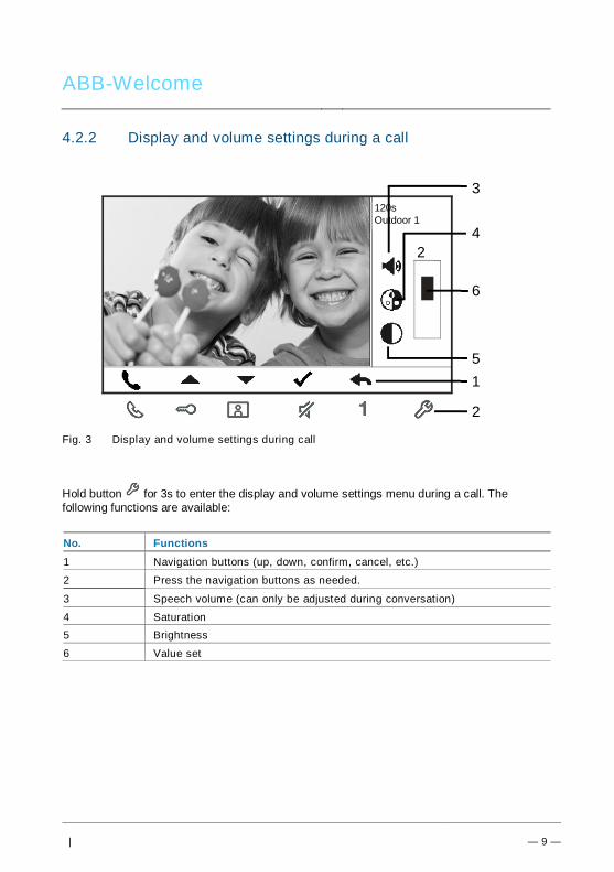
ABB-Welcome
| — 9 —
Pos: 30 /Di nA4 - A nleitu ngen Onlin e/Ueb ersc hrift en/3 ./Tuer oeff nen @ 2 0\mo d_1 323 263 277 453 _15. docx @ 11 193 5 @ 3 @ 1
4.2.2 Display and volume settings during a callPos: 31 /Di nA4 - A nleitu ngen Onlin e/In halt/KNX/Do orEnt ry/83 220 -AP-xxx/ Tue r o effne n - 832 20-AP-x xx @ 20\m od_ 132 326 795 847 9_15 .docx @ 1 121 09 @ @ 1
Fig. 3 Display and volume settings during call
Hold button for 3s to enter the display and volume settings menu during a call. Thefollowing functions are available:
No. Functions1 Navigation buttons (up, down, confirm, cancel, etc.)
2 Press the navigation buttons as needed.
3 Speech volume (can only be adjusted during conversation)
4 Saturation5 Brightness
6 Value set
Pos: 32 /B usch-J aeg er (Neus truk tur )/M odul -Strukt ur/O nline -Doku me ntatio n/Steu er mod ule - Onlin e-Dok ume ntati on ( -- > Für alle Dok ume nte <- -)/ +++ ++ ++ +++ ++ S eiten umb ruch + +++ ++ ++ +++ + @ 9\m od_ 126 8898 668 093 _0. docx @ 521 49 @ @ 1
120sOutdoor 1
24
5
6
1
2
3
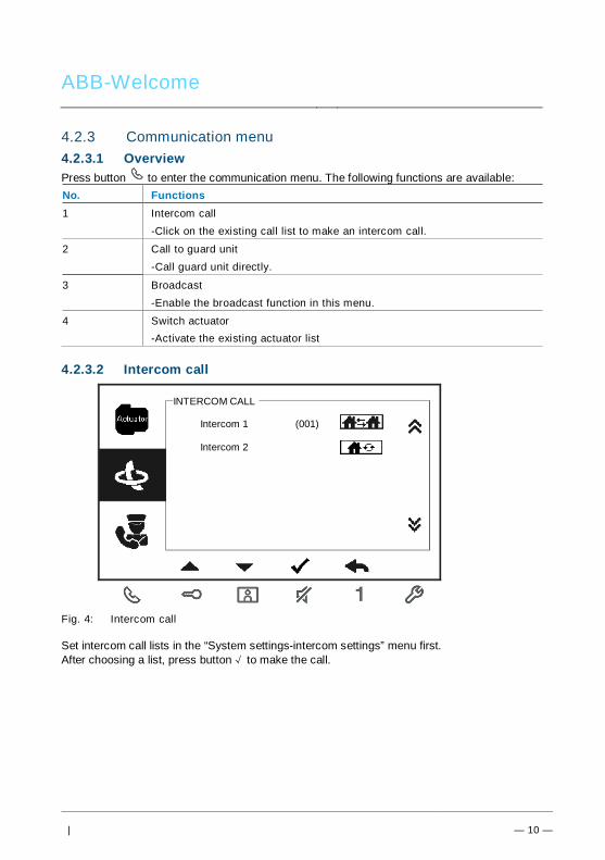
ABB-Welcome
| — 10 —
Pos: 33 /Di nA4 - A nleitu ngen Onlin e/Ueb ersc hrift en/3 ./Stum m sc halte n @ 2 0\m od_ 132 326 360 7142 _15 .docx @ 1 119 51 @ 3 @ 1Pos: 66 /B usch-J aeg er (Neus truk tur )/M odul -Strukt ur/O nline -Doku me ntatio n/Steu er mod ule - Onlin e-Dok ume ntati on ( -- > Für alle Dok ume nte <- -)/ +++ ++ ++ +++ ++ S eiten umb ruch + +++ ++ ++ +++ + @ 9\m od_ 126 8898 668 093 _0. docx @ 521 49 @ @ 1
4.2.3 Communication menuPos: 31 /Di nA4 - A nleitu ngen Onlin e/In halt/KNX/Do orEnt ry/83 220 -AP-xxx/ Tue r o effne n - 832 20-AP-x xx @ 20\m od_ 132 326 795 847 9_15 .docx @ 1 121 09 @ @ 1
4.2.3.1 OverviewPress button to enter the communication menu. The following functions are available:No. Functions1 Intercom call
-Click on the existing call list to make an intercom call.
2 Call to guard unit-Call guard unit directly.
3 Broadcast-Enable the broadcast function in this menu.
4 Switch actuator-Activate the existing actuator list
4.2.3.2 Intercom call
Fig. 4: Intercom call
Set intercom call lists in the “System settings-intercom settings” menu first.After choosing a list, press button√ to make the call.
INTERCOM CALL
Intercom 1 (001)
Intercom 2

ABB-Welcome
| — 11 —
4.2.3.3 Call to guard unit
Fig. 5: Call to guard unit
4.2.3.4 Broadcast
Fig. 6: Broadcast call
CALL GUARD UNIT
Call Guard Unit
BROADCAST
Long-pressing “√“ button to broadcast

ABB-Welcome
| — 12 —
4.2.3.5 Switch actuator
Fig. 7: Switch actuator
Set the actuator list in the “system settings-switch actuator” menu first.After choosing a list, press button √ to enable the lock or light that is connected to the switchactuator.
SWITCH ACTUATOR
Actuator 1 (001)

ABB-Welcome
| — 13 —
4.3 Settings4.3.1 OverviewPress button to enter the system settings menu. The following functions are available:No. Functions1 Intercom settings
-Set intercom lists among different apartments or within the sameapartment
2 Switch actuator-Set the actuator list in this menu
3 Program button-Set functions for programmable buttons
4 Call forward-Set the target (e.g. other indoor stations or guard units) where you wish to
forward calls from visitors while you are away.
5 Auto unlock-Set the automatic unlock time range
6 Set outdoor station password-Set a customized door open password, which is available together witha keypad at an outdoor station.
7 Ringtone-Set the ringtone for outdoor bells, indoor bell or others
8 Volume-Set ringtone volumes
9 Date and time-Set different times.
10 Other settings-Other settings, e.g. auto full screen
11 Blacklist-Set a blacklist that is used to prevent unwanted calls from otherapartment(s)
12 History-View all communication entries in the menu, e.g. received calls and
missed calls.
13 Language-Set the local language
14 Information
15 Reset factory defaultPos: 27 /Di nA4 - A nleitu ngen Onlin e/Ueb ersc hrift en/3 ./Spr ech- und Videov erbi ndu ng @ 20\ mod _13 232 6236 870 0_1 5.do cx @ 1119 27 @ 3 @ 1

ABB-Welcome
| — 14 —
4.3.2 Intercom call settings
Fig. 8: Intercom settings menu
No. Functions1 Choose the previous selection or scroll up
2 Choose the next selection or scroll down
3 Confirm the selection you choose or enter to edit it
4 Return to the previous screen
5 Add a new intercom list. A total of 32 intercom lists can be added.
6 Existing intercom list: Press button √ to modify the settings. means an external intercom from different
apartments.*For establishing an external intercom, each apartment must have a master
indoor station.
7 Existing intercom list: Press button √ to modify the settings. means an internal intercom in the sameapartment.
1 2 3
6
4
Intercom 1 (001)
Intercom 2
Add New 5

ABB-Welcome
| — 15 —
Add a new list
Fig. 9: Add a new intercom
No. Functions1 Enter to choose the call type:
-an external intercom means a call from different apartments-an internal intercom means a call within the same apartment
2 Enter to change the target address, from 001 to 250.*If the call type is the internal intercom, there is no need to set the target
address.
3 Rename the intercom list:Scroll through letters of the alphabet or numbers one by one with “+” or“-” button
After setting, press “save” tor confirm.
1Call Type External Intercom
Target Address
Rename 3
INTERCOM
001
mike
Save Cancel
2

ABB-Welcome
| — 16 —
4.3.3 Switch actuator settings
Fig. 10: Switch actuator settings
No. Functions1 Existing switch actuator list. Press button √ to modify the settings.2 Add a new actuator list. A total of 10 switch actuator lists can be added.
3 Enter to change target address with “+” or “-” button from 001 to 199.
4 Rename the switch actuator list:Scroll through letters of the alphabet or numbers one by one with “+” or “-” button
3
4
SWITCH ACTUATOR
Actuator 1 (001)
Add New
Target Address
Rename
002
light
Save Cancel
SWITCH ACTUATOR
2
1
Add a new list
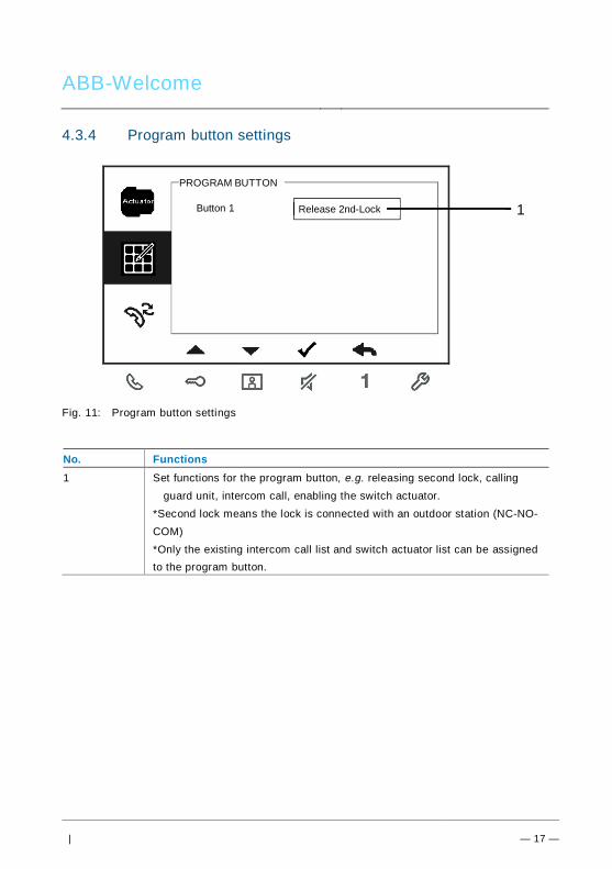
ABB-Welcome
| — 17 —
4.3.4 Program button settings
Fig. 11: Program button settings
No. Functions1 Set functions for the program button, e.g. releasing second lock, calling
guard unit, intercom call, enabling the switch actuator.*Second lock means the lock is connected with an outdoor station (NC-NO-COM)*Only the existing intercom call list and switch actuator list can be assignedto the program button.
Button 1 Release 2nd-Lock
PROGRAM BUTTON
1
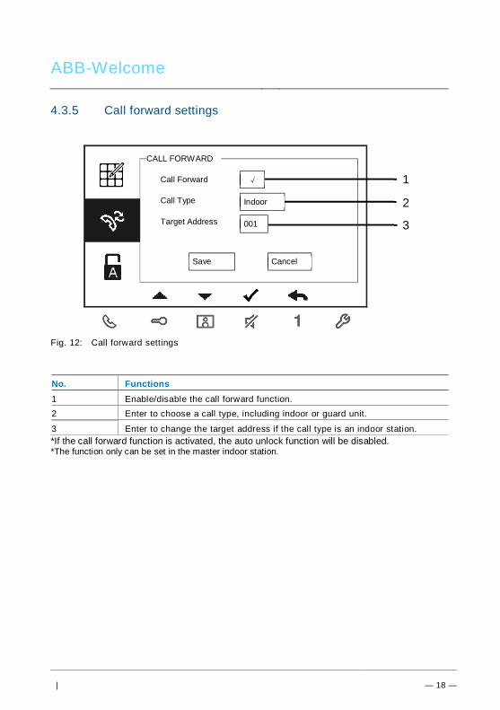
ABB-Welcome
| — 18 —
4.3.5 Call forward settings
Fig. 12: Call forward settings
No. Functions1 Enable/disable the call forward function.2 Enter to choose a call type, including indoor or guard unit.
3 Enter to change the target address if the call type is an indoor station.*If the call forward function is activated, the auto unlock function will be disabled.*The function only can be set in the master indoor station.
1
2
Call Forward
Call Type
√
Indoor
Save Cancel
CALL FORWARD
Target Address 001 31

ABB-Welcome
| — 19 —
4.3.6 Auto unlock settings
Fig. 13: Auto unlock settings
No. Functions1 Enable/disable the auto unlock function.
2 Enable/disable the auto unlock during Time 1.
3 Set starting time and ending time for Time 1
4 Enable/disable auto unlock during Time 2.
5 Set starting time and ending time for Time 2.*If you activate the auto unlock function without setting exact working time, this function will beavailable for 10 hours.*If the auto unlock function is activated, the call forward function will be disabled.*The function only can be set in master indoor station..
1Auto Unlock
Time 1
2
AUTO UNLOCK
√
√
08 00
17 00
:
:
Time 2 X
00 00
00 00
:
:
4
35

ABB-Welcome
| — 20 —
4.3.7 Outdoor station password settings
Fig. 14: Outdoor station password settings
No. Functions1 Enable/disable the password functions
2 Enter a 3-8 digit password.*only available with the keypad.*The function can only be set in the master indoor station.
1Enable Password
Enter Password(3-8 digits)
SET OS PASSWORD
√
12345678 2

ABB-Welcome
| — 21 —
4.3.8 Ringtone settings
Fig. 15: Ringtone
No. Functions1 Select the bell sound for the default outdoor station.
2 Select the bell sound for other outdoor stations.
3 Select the bell sound for the apartment door.
4 Select the bell sound for others, e.g., a call from the guard unit, or anintercom call from other apartments.
1Default Outdoor
Other Outdoors
RING TONE
Ring Tone 1
Ring Tone 2 2
Doorbell Ring Tone 3
Others Ring Tone 4
3
4

ABB-Welcome
| — 22 —
4.3.9 Volume settings
Fig. 16: Volume settings
No. Functions1 Set the volume of bell sound.
2 Enable/disable the feedback tone that sounds when the touch button ispressed.
3 The ringtone can be set as fixed or cycled.
1Ringtone Volume
Touchbutton Tone
VOLUME
Volume 3
2√
Repeated Tone √ 3

ABB-Welcome
| — 23 —
4.3.10 Date and time settings
Fig. 17: Date and time settings
No. Functions1 Set the date.
2 Set the time.
3 Enable/disable the summertime function.
1Date(YYYY-MM-DD)
Time
DATE AND TIME
2013
208
Summer Time √
: 00
- 01 - 01
3
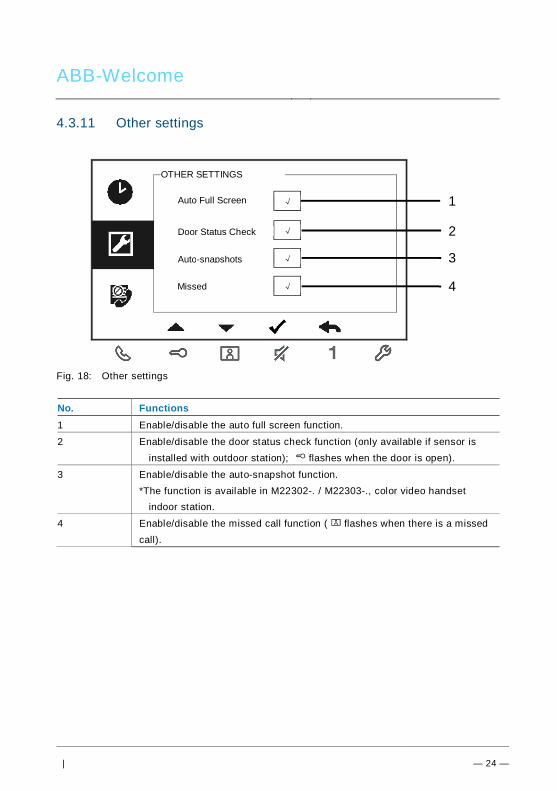
ABB-Welcome
| — 24 —
4.3.11 Other settings
Fig. 18: Other settings
No. Functions1 Enable/disable the auto full screen function.
2 Enable/disable the door status check function (only available if sensor isinstalled with outdoor station); flashes when the door is open).
3 Enable/disable the auto-snapshot function.*The function is available in M22302-. / M22303-., color video handset
indoor station.
4 Enable/disable the missed call function ( flashes when there is a missedcall).
1Auto Full Screen
Auto-snapshots
OTHER SETTINGS
2
√
3
Missed
√
√
√ 4
Door Status Check

ABB-Welcome
| — 25 —
4.3.12 Blacklist settings
Fig. 19: Blacklist settings
No. Functions1 Existing blacklist: Press button √ to modify the settings.
2 Add new blacklist(s). A total of 32 blacklists can be added.
3 Enter to change the target address with “+” or “-” button from 001 to 250.*The function only can be set in the master indoor station.
Blacklist 1
Add New
BLACKLIST
(001)
Target Address
BLACKLIST
Save Cancel
002
1
2
3

ABB-Welcome
| — 26 —
4.3.13 History review
Fig. 20: History review
No. Functions1 Up to 100 events can be recorded in the history menu.
-If the snapshot function is enabled, an icon will display. If snapshotfunction is not enabled, icon will not display.
-Date, time and type of the event are recorded together with the snapshot.- Directions: means dialing calls means receiving calls
●
HISTORY
1/2Outdoor -1
1/632013-03-2116:45
Outdoor - 1
● 2013-03-2116:45
Outdoor - 1
● 2013-03-2114:24
Outdoor - 1
1
2
3
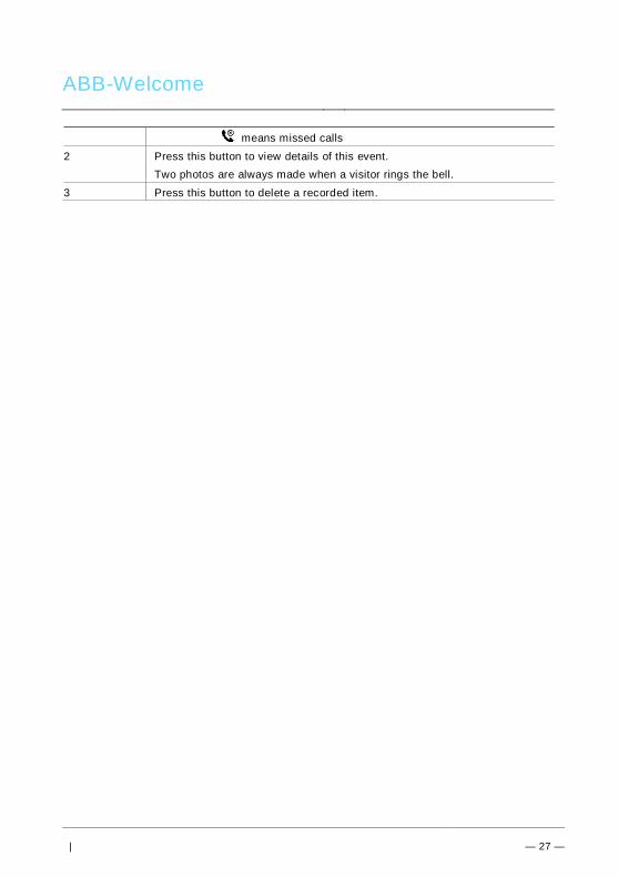
ABB-Welcome
| — 27 —
means missed calls
2 Press this button to view details of this event.Two photos are always made when a visitor rings the bell.
3 Press this button to delete a recorded item.

ABB-Welcome
| — 28 —
4.3.14 Camera list
CAMERA LIST
The list is disabled
Outdoor1-1
Outdoor1-2
Camera1
1
2
3
CAMERA LIST- Camera 1
Enable
Rename
√
Front door
Visible doorbell √
Save Cancel
4
5

ABB-Welcome
| — 29 —
No. Functions1 Display status of the camera list.
Only if the list is enable, user can make an surveilliance according to thislist, and also user can edit each surveilliance object in the list.
2 Display the camera from camera interface.
3 Press this button to enable or disable camera list.Default is set as disable.
4 Set name of camera (1-14 characters).Characters must be letters or digits.
5 This option can be set only when a camera interface (mode=4) isassociated with this indoor station.
Only one camera can be set as available.When the pushbutton is pressed, the image from the camera connected to
the camera interface will display on the indoor station.

ABB-Welcome
| — 30 —
4.3.15 Language settings
Fig. 21: Language settings
4.3.16 Information
Fig. 22: Information for outdoor station. (Scan QR code to get detailed instructions.)
English
LANGUAGE
Française
Italiano
Português
Español
Flash Version: V2.07_150629
INFORMATION
MCU Version: V2.07_150703
M/S: Master
Default Outdoor: 1
Indoor St. Add.: 001

ABB-Welcome
| — 31 —
4.3.17 Reseting factory default
Fig. 23: Resetting factory defaults
No. Functions1 Reset all settings:
Reset the device and restore all default configurations. The operationdoes not delete the programmed data and history such as intercom listsand switch actuator lists.
2 Clear all data:Delete all programmed data and history. All configurations will berestored to factory default settings.
Are you sure to reset?
RESET FACTORY DEFAULT
Cancel OK
Reset All Settings
Clear All Data ×
√

ABB-Welcome
| — 32 —
Pos: 67 /Di nA4 - A nleitu ngen Onlin e/Ueb ersc hrift en/2 ./Reini gung @ 1 9\m od_ 131 0733 980 533 _15. docx @ 10 785 3 @ 2 @ 1
4.4 CleaningPos: 68 /Di nA4 - A nleitu ngen Onlin e/In halt/KNX/Do orEnt ry/Reini gun g/Reini gun g Touchsc ree nm onito r @ 19\m od_ 131 073 410 897 8_15 .docx @ 1 078 62 @ @ 1
CautionRisk of damage to the screen surface.The screen surface can be damaged by hard or sharp objects!Never use such objects for entries on the touch screen monitor.– Use your finger or a plastic stylus.
The screen surface can be damaged by cleaning fluids or abrasiveagents!– Clean the surfaces using a soft cloth and commercially available
glass cleaner.– Never use abrasive cleaning agents.
Pos: 69 /B usch-J aeg er (Neus truk tur )/M odul -Strukt ur/O nline -Doku me ntatio n/Steu er mod ule - Onlin e-Dok ume ntati on ( -- > Für alle Dok ume nte <- -)/ +++ ++ ++ +++ ++ S eiten umb ruch + +++ ++ ++ +++ + @ 9\m od_ 126 8898 668 093 _0. docx @ 521 49 @ @ 1

ABB-Welcome
| — 33 —
Pos: 70 /Di nA4 - A nleitu ngen Onlin e/Ueb ersc hrift en/2 ./Ge raet eeins tellun gen @ 1 8\mo d_1 302 768 847 744 _15. docx @ 10 354 8 @ 2 @ 1
4.5 Adjusting the devicePos: 71 /Di nA4 - A nleitu ngen Onlin e/Ueb ersc hrift en/3 ./Abschl usswide rsta nd @ 19\ mod _13 219 5807 990 6_1 5.do cx @ 1100 83 @ 3 @ 1
Pos: 72 /Di nA4 - A nleitu ngen Onlin e/In halt/KNX/Do orEnt ry/Bedie nun g/Abschl usswide rsta nd s etzen 83 220 -AP-xxx @ 19\ mod _13 1072 339 236 9_1 5.do cx @ 1 078 41 @ @ 1
Fig. 24:Pos: 74 /Di nA4 - A nleitu ngen Onlin e/In halt/KNX/Do orEnt ry/Bedie nun g/M aste r/Slave Sc halte r setz en 832 20-AP-xxx @ 1 9\m od_1 310 723 320 966 _15. docx @ 10 783 3 @ @
1. StationSelect switch to set the address of default outdoor station.
2. X10 X1Select switches to set the address (1-99) of the indoor station.X200 X100Select dip-switches to set the address (hundreds digits) of the indoor station.
3. Master/slave functionOnly one indoor station in each apartment should be set as "master" (Switchshould be set as “M/S on”). All additional indoor stations in the same apartmentmust be set as "slave" (Switch should be set as “M/S off.”)
4. Terminal resistorIn video installations or mixed audio and video installations, the switch must be setas “RC on” on the last device of the line.
5. a b = Bus connection= Doorbell connection
DC GND = Additional power supply6. Connector for induction loopPos: 75 /B usch-J aeg er (Neus truk tur )/M odul -Strukt ur/O nline -Doku me ntatio n/Steu er mod ule - Onlin e-Dok ume ntati on ( -- > Für alle Dok ume nte <- -)/ +++ ++ ++ +++ ++ S eiten umb ruch + +++ ++ ++ +++ + @ 9\m od_ 126 8898 668 093 _0. docx @ 521 49 @ @ 1

ABB-Welcome
| — 34 —
Pos: 76 /Di nA4 - A nleitu ngen Onlin e/Ueb ersc hrift en/1 ./Technisc he D aten @ 18 \mo d_1 302 615 863 001 _15. docx @ 10 341 6 @ 1 @ 1
5 Technical dataPos: 77 /Di nA4 - A nleitu ngen Onlin e/In halt/KNX/Do orEnt ry/83 220 -AP-xxx/ Tech nische Date n - 832 20-AP-x xx @ 1 8\m od_ 130 321 285 4559 _15 .docx @ 1 037 05 @ @ 1
Designation ValueDisplay resolution: 480 x 272
Display size: 4.3”
Operating temperature -10 °C - +55 °C
Storage temperature -40 °C - +70 °CProtection IP 30
Single-wire clamps 2 x 0.28 mm² - 2 x 0.75 mm²
Fine-wire clamps 2 x 0.28 mm² - 2 x 0.75 mm²
Bus voltage 20-30 V
Size 137 mm x 155 mm x 24 mm
Pos: 78 /B usch-J aeg er (Neus truk tur )/M odul -Strukt ur/O nline -Doku me ntatio n/Steu er mod ule - Onlin e-Dok ume ntati on ( -- > Für alle Dok ume nte <- -)/ +++ ++ ++ +++ ++ S eiten umb ruch + +++ ++ ++ +++ + @ 9\m od_ 126 8898 668 093 _0. docx @ 521 49 @ @ 1
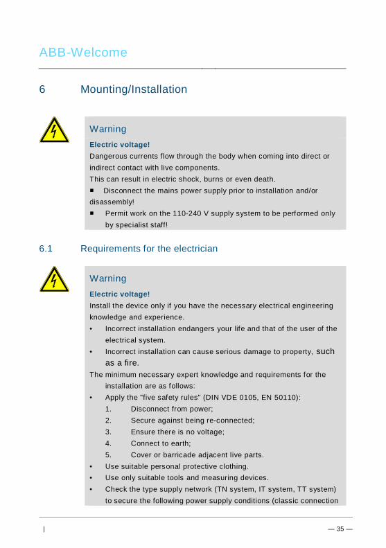
ABB-Welcome
| — 35 —
Pos: 79 /B usch-J aeg er (Neus truk tur )/M odul -Strukt ur/O nline -Doku me ntatio n/Übe rsch rifte n ( --> Fü r alle Doku men te < -- )/1. E bene /M - O/ Mont age / Ins tallatio n @ 18\ mod _13 0261 396 611 1_1 5.do cx @ 1 033 73 @ 1 @ 1
6 Mounting/InstallationPos: 80 /B usch-J aeg er (Neus truk tur )/M odul -Strukt ur/O nline -Doku me ntatio n/Siche rheit (- -> Fü r alle D oku ment e < --) /War nhinweis e/Siche rheit - Nie ders pan nun gs- und 230 V-Leit ung en @ 18\ mod _13 026 178 214 91_1 5.d ocx @ 103 465 @ @ 1
WarningElectric voltage!Dangerous currents flow through the body when coming into direct orindirect contact with live components.This can result in electric shock, burns or even death.■ Disconnect the mains power supply prior to installation and/ordisassembly!■ Permit work on the 110-240 V supply system to be performed only
by specialist staff!
Pos: 81 /B usch-J aeg er (Neus truk tur )/M odul -Strukt ur/O nline -Doku me ntatio n/Siche rheit (- -> Fü r alle D oku ment e < --) /War nhinweis e/Siche rheit - Fachk enn tnisse @ 18 \mo d_1 302 774 384 017_ 15. docx @ 10 356 4 @ 2 @ 1
6.1 Requirements for the electrician
WarningElectric voltage!Install the device only if you have the necessary electrical engineeringknowledge and experience.• Incorrect installation endangers your life and that of the user of the
electrical system.• Incorrect installation can cause serious damage to property, such
as a fire.The minimum necessary expert knowledge and requirements for the
installation are as follows:• Apply the "five safety rules" (DIN VDE 0105, EN 50110):
1. Disconnect from power;2. Secure against being re-connected;3. Ensure there is no voltage;4. Connect to earth;5. Cover or barricade adjacent live parts.
• Use suitable personal protective clothing.• Use only suitable tools and measuring devices.• Check the type supply network (TN system, IT system, TT system)
to secure the following power supply conditions (classic connection
ABB-Welcome
| — 36 —
to ground, protective earthing, necessary additional measures,etc.).
Pos: 82 /Di nA4 - A nleitu ngen Onlin e/In halt/KNX/Do orEnt ry/M onta ge/ Mont age hinweis e - Allg emei n @ 1 9\m od_ 131 056 367 047 8_15 .docx @ 1 077 43 @ 2 @ 1
6.2 General installation instructions• Terminate all branches of the wiring system via a connected bus device (e.g.,
indoor station, outdoor station, system device).• Do not install the system controller directly next to the bell transformer and other
power supplies (to avoid interference).• Do not install the wires of the system bus together with 100-240 V wires.• Do not use common cables for the connecting wires of the door openers and wires
of the system bus.• Avoid bridges between different cable types.• Use only two wires for the system bus in a four-core or multi-core cable.• When looping, never install the incoming and outgoing bus inside the same cable.• Never install the internal and external bus inside the same cable.Pos: 83 /B usch-J aeg er (Neus truk tur )/M odul -Strukt ur/O nline -Doku me ntatio n/Steu er mod ule - Onlin e-Dok ume ntati on ( -- > Für alle Dok ume nte <- -)/ +++ ++ ++ +++ ++ S eiten umb ruch + +++ ++ ++ +++ + @ 9\m od_ 126 8898 668 093 _0. docx @ 521 49 @ @ 1

ABB-Welcome
| — 37 —
Pos: 84 /B usch-J aeg er (Neus truk tur )/M odul -Strukt ur/O nline -Doku me ntatio n/Übe rsch rifte n ( --> Fü r alle Doku men te < -- )/2. E bene /M - O/ Mont age @ 1 8\m od_1 302 615 960 458 _15. docx @ 10 342 4 @ 2 @ 1
6.3 MountingPos: 85. 1 /DinA4 - Anleit ung en O nline/I nhal t/KNX/DoorE ntry/ 832 20-AP-xxx /Mo nta ge - Mo dule/ Mon tag e - Mon tage dos e -- 83 220 -AP-xxx @ 19\ mod _132 325 040 684 8_1 5.doc x @ 1 110 98 @ @ 1
Recommended installation height
Dismantling
Open the housing of the panel by pulling the clamp at the bottom of the device.
1.5 meters (4.9 feet)

ABB-Welcome
| — 38 —
Installation dimension
1. The bottom of the device has screw holes for fastening on the wall according to theabove dimension instructions.
2. In addition, the bottom of the device can be fixed to the existing flush-mounted box.The dimension of the compatible flush-mounted box is shown in illustration above.
Wiring
Affix the bottom of the device and connect it in accordance with the illustration. Theinsulated section of the cable end must not be longer than 10 mm.

ABB-Welcome
| — 39 —
SettingsSet addresses of the preferred outdoor stations and the address of the indoor station onthe jumper. (See Chapter 4.5, Adjusting the device.)
Three types of installation:A. Surface-mounted1) Mounted on the wall
1. Affix the bottom of the device to the wall.2. Latch the upper part of the device onto the bottom. Place the upper side of the
device on the lock-in lugs and then press the bottom side onto the bottom part ofthe device until it is caught by the clamp.
2) Mounted with flush-mounted box
1. Affix the bottom of the device to the existing flush-mounted box.2. Latch the upper part of the device onto the bottom part. Place the upper side of the
device on the lock-in lugs and then press the bottom side onto the bottom part ofthe device until it is caught by the clamp.

ABB-Welcome
| — 40 —
B. Desktop-mountedMounted with desktop bracket
1. Affix the bottom of the device to the desktop bracket.2. Latch the upper part of the device onto the bottom part. Place the upper side of the
device on the lock-in lugs and then press the bottom side onto the bottom part ofthe device until it is caught by the clamp.
C. Flush-mountedDismantling the frame
For flush-mounted installation, dismantle the frame first.
1) Mounted with back cover
1. Affix the back cover inside the wall directly.

ABB-Welcome
| — 41 —
2. Latch the upper part of the device onto the bottom part. Place the upper side of thedevice on the lock-in lugs and then press the bottom side onto the bottom part ofthe device until it is caught by the clamp.
2) Mounted with metal flush-mounted box
1. Affix the metal flush-mounted box inside the wall.2. Affix the back cover to the metal flush-mounted box.3. Latch the upper part of the device onto the bottom part. Place the upper side of the
device on the lock-in lugs and then press the bottom side onto the bottom part ofthe device until it is caught by the clamp.
3) Mounted with cavity wall

ABB-Welcome
| — 42 —
1. Attach a pair of supporting brackets to the back cover of the indoor station. Place 4screws through the back cover and attach with 4 claw brackets.2. Rotate 4 claw brackets to attach to the supporting brackets and pull the rubberbands around the corner of the claw brackets to fix the claws.3. Put the back cover into the cavity wall4. Tighten the screws5. Latch the upper part of the indoor station onto the bottom part. Place the upper sideof the indoor station on the lock-in lugs and then press the bottom side onto the bottompart of the device until it is caught by the clamp.
Replacing the front cover
The installation of the indoor station is now complete.
Pos: 94 /B usch-J aeg er (Neus truk tur )/M odul -Strukt ur/O nline -Doku me ntatio n/Steu er mod ule - Onlin e-Dok ume ntati on ( -- > Für alle Dok ume nte <- -)/ +++ ++ ++ +++ ++ S eiten umb ruch + +++ ++ ++ +++ + @ 9\m od_ 126 8898 668 093 _0. docx @ 521 49 @ @ 1

ABB-Welcome
Pos: 95 /Di nA4 - A nleitu ngen Onlin e/In halt/KNX/Do orEnt ry/Proj ektier ung -M erkbl att/Pr ojektie rPos: 9 7 /Busc h-Ja ege r (N eust ruktu r)/ Mo dul-Str uktu r/Onli ne-D oku ment ation /Rückseit en (-- > Für alle Dok um ente <- -)/R ückseit e - Bus ch-J aeg er - Allgem ein @ 20\ mod _13 273 200 748 86_1 5.d ocx @ 137 103 @ @ 1
Notice=== E nde der Liste für Tex tma rke Ba ckcove r = ==
We reserve the right to, at any time, make technical changes or changes in the contentof this document without prior notice.The detailed specifications agreed to at the time of ordering applies to all orders. ABBaccepts no responsibility for possible errors or incompleteness in this document. We reserve all rights to this document and the topics and illustrations contained therein.The document and its contents, or excerpts thereof, must not be reproduced,transmitted or reused by third parties without prior written consent by ABB.