ABB PULSE ANALOG INTERFACE ROBOTIC INTERFACE … - f15-999/control... · abb pulse analog interface...
32
ABB PULSE ANALOG INTERFACE ROBOTIC INTERFACE APPLICATION: MIG AND PULSE MIG WELDING ROBOT ANALOG INT P/N ABB RI-1P PULSE 34380 INSTRUCTION MANUAL These INSTRUCTIONS are for experienced operators. If you are not fully familiar with the principles of operation and safe practices for arc welding equipment, we urge you to read our booklet, "Precautions and Safe Practices for Arc Welding, Cutting, and Gouging", Form 52-529. Do NOT permit untrained persons to install, operate, or maintain this equipment. Do NOT attempt to install or operate this equipment until you have read and fully understand these instructions. If you do not fully understand these instructions, contact your supplier for further information. Be sure to read the Safety Precautions (Section I) before installing or operating this equipment. Be sure this information reaches the operator. You can get extra copies through your supplier. F-15-151-B September, 2000
Transcript of ABB PULSE ANALOG INTERFACE ROBOTIC INTERFACE … - f15-999/control... · abb pulse analog interface...

ABB PULSE ANALOG INTERFACEROBOTIC INTERFACE
APPLICATION:MIG AND PULSE MIG WELDING
ROBOT ANALOG INT P/NABB RI-1P PULSE 34380
INSTRUCTION MANUAL
These INSTRUCTIONS are for experienced operators. If you are not fully familiar with the principles of operationand safe practices for arc welding equipment, we urge you to read our booklet, "Precautions and Safe Practicesfor Arc Welding, Cutting, and Gouging", Form 52-529. Do NOT permit untrained persons to install, operate, ormaintain this equipment. Do NOT attempt to install or operate this equipment until you have read and fullyunderstand these instructions. If you do not fully understand these instructions, contact your supplier forfurther information. Be sure to read the Safety Precautions (Section I) before installing or operating thisequipment.
Be sure this information reaches the operator.You can get extra copies through your supplier.
F-15-151-BSeptember, 2000
USER RESPONSIBILITY
This equipment will perform in conformity with the description thereof contained in this manual and accompanying labelsand/or inserts when installed, operated, maintained and repaired in accordance with the instructions provided. Thisequipment must be checked periodically. Malfunctioning or poorly maintained equipment should not be used. Partsthat are broken, missing, worn, distorted or contaminated should be replaced immediately. Should such repair orreplacement become necessary, the manufacturer recommends that a telephone or written request for service advicebe made to the Authorized Distributor from whom purchased.
This equipment or any of its parts should not be altered without the prior written approval of the manufacturer. The userof this equipment shall have the sole responsibility for any malfunction which results from improper use, faultymaintenance, damage, improper repair or alteration by anyone other than the manufacturer or a service facilitydesignated by the manufacturer.
TABLE OF CONTENTS
SECTION TITLE PAGEPARAGRAPH
SECTION 1 SAFETY ................................................................................................................................... 3
SECTION 2 DESCRIPTION ........................................................................................................................ 72.1 Introduction .............................................................................................................................. 72.2 Description ............................................................................................................................... 7
SECTION 3 EQUIPMENT............................................................................................................................ 83.1 Equipment Required................................................................................................................. 83.2 Optional Accessories ............................................................................................................... 9
SECTION 4 OPERATION .......................................................................................................................... 104.1 Mounting/Connecting Equipment ........................................................................................... 104.2 Control/Indicators ................................................................................................................... 104.3 Operation ............................................................................................................................... 11
SECTION 5 TROUBLESHOOTING .......................................................................................................... 155.1 Introduction ............................................................................................................................ 155.2 Troubleshooting Guide ........................................................................................................... 155.3 Diagnostic Mode .................................................................................................................... 185.4 Hot Start Adjustment .............................................................................................................. 18
SECTION 6 REPLACEMENT PARTS ....................................................................................................... 216.1 General .................................................................................................................................. 21
Parts....................................................................................................................................... 22
2
3
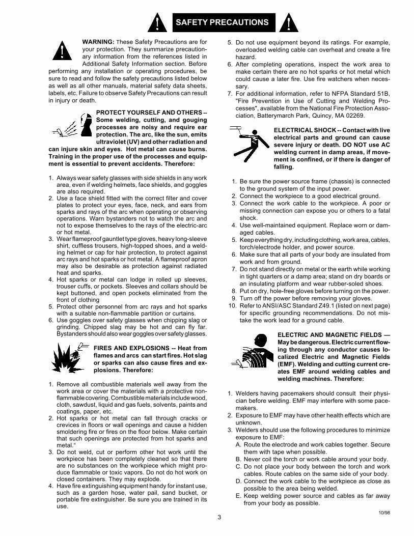
WARNING: These Safety Precautions are foryour protection. They summarize precaution-ary information from the references listed inAdditional Safety Information section. Before
performing any installation or operating procedures, besure to read and follow the safety precautions listed belowas well as all other manuals, material safety data sheets,labels, etc. Failure to observe Safety Precautions can resultin injury or death.
PROTECT YOURSELF AND OTHERS --Some welding, cutting, and gougingprocesses are noisy and require earprotection. The arc, like the sun, emitsultraviolet (UV) and other radiation and
can injure skin and eyes. Hot metal can cause burns.Training in the proper use of the processes and equip-ment is essential to prevent accidents. Therefore:
1. Always wear safety glasses with side shields in any workarea, even if welding helmets, face shields, and gogglesare also required.
2. Use a face shield fitted with the correct filter and coverplates to protect your eyes, face, neck, and ears fromsparks and rays of the arc when operating or observingoperations. Warn bystanders not to watch the arc andnot to expose themselves to the rays of the electric-arcor hot metal.
3. Wear flameproof gauntlet type gloves, heavy long-sleeveshirt, cuffless trousers, high-topped shoes, and a weld-ing helmet or cap for hair protection, to protect againstarc rays and hot sparks or hot metal. A flameproof apronmay also be desirable as protection against radiatedheat and sparks.
4. Hot sparks or metal can lodge in rolled up sleeves,trouser cuffs, or pockets. Sleeves and collars should bekept buttoned, and open pockets eliminated from thefront of clothing
5. Protect other personnel from arc rays and hot sparkswith a suitable non-flammable partition or curtains.
6. Use goggles over safety glasses when chipping slag orgrinding. Chipped slag may be hot and can fly far.Bystanders should also wear goggles over safety glasses.
FIRES AND EXPLOSIONS -- Heat fromflames and arcs can start fires. Hot slagor sparks can also cause fires and ex-plosions. Therefore:
1. Remove all combustible materials well away from thework area or cover the materials with a protective non-flammable covering. Combustible materials include wood,cloth, sawdust, liquid and gas fuels, solvents, paints andcoatings, paper, etc.
2. Hot sparks or hot metal can fall through cracks orcrevices in floors or wall openings and cause a hiddensmoldering fire or fires on the floor below. Make certainthat such openings are protected from hot sparks andmetal.“
3. Do not weld, cut or perform other hot work until theworkpiece has been completely cleaned so that thereare no substances on the workpiece which might pro-duce flammable or toxic vapors. Do not do hot work onclosed containers. They may explode.
4. Have fire extinguishing equipment handy for instant use,such as a garden hose, water pail, sand bucket, orportable fire extinguisher. Be sure you are trained in itsuse.
SAFETY PRECAUTIONS
10/98
5. Do not use equipment beyond its ratings. For example,overloaded welding cable can overheat and create a firehazard.
6. After completing operations, inspect the work area tomake certain there are no hot sparks or hot metal whichcould cause a later fire. Use fire watchers when neces-sary.
7. For additional information, refer to NFPA Standard 51B,"Fire Prevention in Use of Cutting and Welding Pro-cesses", available from the National Fire Protection Asso-ciation, Batterymarch Park, Quincy, MA 02269.
ELECTRICAL SHOCK -- Contact with liveelectrical parts and ground can causesevere injury or death. DO NOT use ACwelding current in damp areas, if move-ment is confined, or if there is danger offalling.
1. Be sure the power source frame (chassis) is connectedto the ground system of the input power.
2. Connect the workpiece to a good electrical ground.3. Connect the work cable to the workpiece. A poor or
missing connection can expose you or others to a fatalshock.
4. Use well-maintained equipment. Replace worn or dam-aged cables.
5. Keep everything dry, including clothing, work area, cables,torch/electrode holder, and power source.
6. Make sure that all parts of your body are insulated fromwork and from ground.
7. Do not stand directly on metal or the earth while workingin tight quarters or a damp area; stand on dry boards oran insulating platform and wear rubber-soled shoes.
8. Put on dry, hole-free gloves before turning on the power.9. Turn off the power before removing your gloves.
10. Refer to ANSI/ASC Standard Z49.1 (listed on next page)for specific grounding recommendations. Do not mis-take the work lead for a ground cable.
ELECTRIC AND MAGNETIC FIELDS —May be dangerous. Electric current flow-ing through any conductor causes lo-calized Electric and Magnetic Fields(EMF). Welding and cutting current cre-ates EMF around welding cables andwelding machines. Therefore:
1. Welders having pacemakers should consult their physi-cian before welding. EMF may interfere with some pace-makers.
2. Exposure to EMF may have other health effects which areunknown.
3. Welders should use the following procedures to minimizeexposure to EMF:A. Route the electrode and work cables together. Secure
them with tape when possible.B. Never coil the torch or work cable around your body.C. Do not place your body between the torch and work
cables. Route cables on the same side of your body.D. Connect the work cable to the workpiece as close as
possible to the area being welded.E. Keep welding power source and cables as far away
from your body as possible.
4
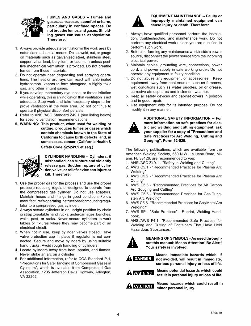
FUMES AND GASES -- Fumes andgases, can cause discomfort or harm,particularly in confined spaces. Donot breathe fumes and gases. Shield-ing gases can cause asphyxiation.Therefore:
1. Always provide adequate ventilation in the work area bynatural or mechanical means. Do not weld, cut, or gougeon materials such as galvanized steel, stainless steel,copper, zinc, lead, beryllium, or cadmium unless posi-tive mechanical ventilation is provided. Do not breathefumes from these materials.
2. Do not operate near degreasing and spraying opera-tions. The heat or arc rays can react with chlorinatedhydrocarbon vapors to form phosgene, a highly toxicgas, and other irritant gases.
3. If you develop momentary eye, nose, or throat irritationwhile operating, this is an indication that ventilation is notadequate. Stop work and take necessary steps to im-prove ventilation in the work area. Do not continue tooperate if physical discomfort persists.
4. Refer to ANSI/ASC Standard Z49.1 (see listing below)for specific ventilation recommendations.
5. WARNING: This product, when used for welding orcutting, produces fumes or gases whichcontain chemicals known to the State ofCalifornia to cause birth defects and, insome cases, cancer. (California Health &Safety Code §25249.5 et seq.)
CYLINDER HANDLING -- Cylinders, ifmishandled, can rupture and violentlyrelease gas. Sudden rupture of cylin-der, valve, or relief device can injure orkill. Therefore:
1. Use the proper gas for the process and use the properpressure reducing regulator designed to operate fromthe compressed gas cylinder. Do not use adaptors.Maintain hoses and fittings in good condition. Followmanufacturer's operating instructions for mounting regu-lator to a compressed gas cylinder.
2. Always secure cylinders in an upright position by chainor strap to suitable hand trucks, undercarriages, benches,walls, post, or racks. Never secure cylinders to worktables or fixtures where they may become part of anelectrical circuit.
3. When not in use, keep cylinder valves closed. Havevalve protection cap in place if regulator is not con-nected. Secure and move cylinders by using suitablehand trucks. Avoid rough handling of cylinders.
4. Locate cylinders away from heat, sparks, and flames.Never strike an arc on a cylinder.
5. For additional information, refer to CGA Standard P-1,"Precautions for Safe Handling of Compressed Gases inCylinders", which is available from Compressed GasAssociation, 1235 Jefferson Davis Highway, Arlington,VA 22202.
EQUIPMENT MAINTENANCE -- Faulty orimproperly maintained equipment cancause injury or death. Therefore:
1. Always have qualified personnel perform the installa-tion, troubleshooting, and maintenance work. Do notperform any electrical work unless you are qualified toperform such work.
2. Before performing any maintenance work inside a powersource, disconnect the power source from the incomingelectrical power.
3. Maintain cables, grounding wire, connections, powercord, and power supply in safe working order. Do notoperate any equipment in faulty condition.
4. Do not abuse any equipment or accessories. Keepequipment away from heat sources such as furnaces,wet conditions such as water puddles, oil or grease,corrosive atmospheres and inclement weather.
5. Keep all safety devices and cabinet covers in positionand in good repair.
6. Use equipment only for its intended purpose. Do notmodify it in any manner.
ADDITIONAL SAFETY INFORMATION -- Formore information on safe practices for elec-tric arc welding and cutting equipment, askyour supplier for a copy of "Precautions andSafe Practices for Arc Welding, Cutting andGouging", Form 52-529.
The following publications, which are available from theAmerican Welding Society, 550 N.W. LeJuene Road, Mi-ami, FL 33126, are recommended to you:1. ANSI/ASC Z49.1 - "Safety in Welding and Cutting"2. AWS C5.1 - "Recommended Practices for Plasma Arc
Welding"3. AWS C5.2 - "Recommended Practices for Plasma Arc
Cutting"4. AWS C5.3 - "Recommended Practices for Air Carbon
Arc Gouging and Cutting"5. AWS C5.5 - "Recommended Practices for Gas Tung-
sten Arc Welding“6. AWS C5.6 - "Recommended Practices for Gas Metal Arc
Welding"“7. AWS SP - "Safe Practices" - Reprint, Welding Hand-
book.8. ANSI/AWS F4.1, "Recommended Safe Practices for
Welding and Cutting of Containers That Have HeldHazardous Substances."
MEANING OF SYMBOLS - As used through-out this manual: Means Attention! Be Alert!Your safety is involved.
Means immediate hazards which, ifnot avoided, will result in immediate,serious personal injury or loss of life.
Means potential hazards which couldresult in personal injury or loss of life.
Means hazards which could result inminor personal injury.
SP98-10
5
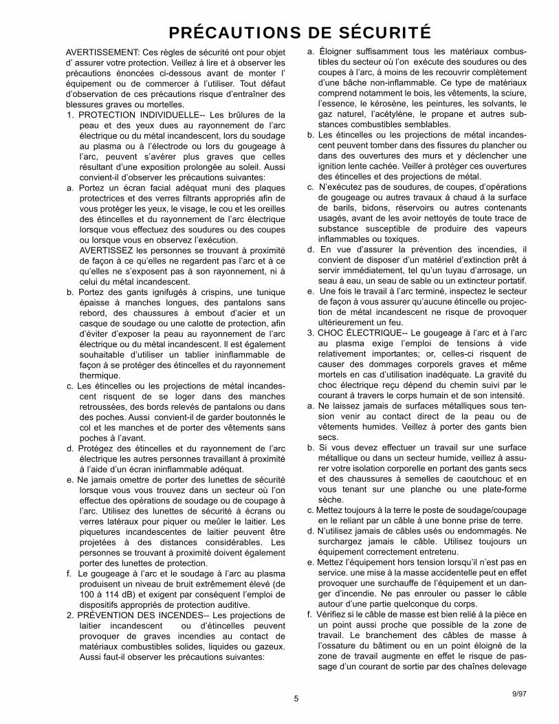
a. Éloigner suffisamment tous les matériaux combus-tibles du secteur où l’on exécute des soudures ou descoupes à l’arc, à moins de les recouvrir complètementd’une bâche non-inflammable. Ce type de matériauxcomprend notamment le bois, les vêtements, la sciure,l’essence, le kérosène, les peintures, les solvants, legaz naturel, l’acétylène, le propane et autres sub-stances combustibles semblables.
b. Les étincelles ou les projections de métal incandes-cent peuvent tomber dans des fissures du plancher oudans des ouvertures des murs et y déclencher uneignition lente cachée. Veiller à protéger ces ouverturesdes étincelles et des projections de métal.
c. N’exécutez pas de soudures, de coupes, d’opérationsde gougeage ou autres travaux à chaud à la surfacede barils, bidons, réservoirs ou autres contenantsusagés, avant de les avoir nettoyés de toute trace desubstance susceptible de produire des vapeursinflammables ou toxiques.
d. En vue d’assurer la prévention des incendies, ilconvient de disposer d’un matériel d’extinction prêt àservir immédiatement, tel qu’un tuyau d’arrosage, unseau à eau, un seau de sable ou un extincteur portatif.
e. Une fois le travail à l’arc terminé, inspectez le secteurde façon à vous assurer qu’aucune étincelle ou projec-tion de métal incandescent ne risque de provoquerultérieurement un feu.
3. CHOC ÉLECTRIQUE-- Le gougeage à l’arc et à l’arcau plasma exige l’emploi de tensions à viderelativement importantes; or, celles-ci risquent decauser des dommages corporels graves et mêmemortels en cas d’utilisation inadéquate. La gravité duchoc électrique reçu dépend du chemin suivi par lecourant à travers le corps humain et de son intensité.
a. Ne laissez jamais de surfaces métalliques sous ten-sion venir au contact direct de la peau ou devêtements humides. Veillez à porter des gants biensecs.
b. Si vous devez effectuer un travail sur une surfacemétallique ou dans un secteur humide, veillez à assu-rer votre isolation corporelle en portant des gants secset des chaussures à semelles de caoutchouc et envous tenant sur une planche ou une plate-formesèche.
c. Mettez toujours à la terre le poste de soudage/coupageen le reliant par un câble à une bonne prise de terre.
d. N’utilisez jamais de câbles usés ou endommagés. Nesurchargez jamais le câble. Utilisez toujours unéquipement correctement entretenu.
e. Mettez l’équipement hors tension lorsqu’il n’est pas enservice. une mise à la masse accidentelle peut en effetprovoquer une surchauffe de l’équipement et un dan-ger d’incendie. Ne pas enrouler ou passer le câbleautour d’une partie quelconque du corps.
f. Vérifiez si le câble de masse est bien relié à la pièce enun point aussi proche que possible de la zone detravail. Le branchement des câbles de masse àl’ossature du bâtiment ou en un point éloigné de lazone de travail augmente en effet le risque de pas-sage d’un courant de sortie par des chaînes delevage
PRÉCAUTIONS DE SÉCURITÉAVERTISSEMENT: Ces règles de sécurité ont pour objetd’ assurer votre protection. Veillez à lire et à observer lesprécautions énoncées ci-dessous avant de monter l’équipement ou de commercer à l’utiliser. Tout défautd’observation de ces précautions risque d’entraîner desblessures graves ou mortelles.1. PROTECTION INDIVIDUELLE-- Les brûlures de la
peau et des yeux dues au rayonnement de l’arcélectrique ou du métal incandescent, lors du soudageau plasma ou à l’électrode ou lors du gougeage àl’arc, peuvent s’avérer plus graves que cellesrésultant d’une exposition prolongée au soleil. Aussiconvient-il d’observer les précautions suivantes:
a. Portez un écran facial adéquat muni des plaquesprotectrices et des verres filtrants appropriés afin devous protéger les yeux, le visage, le cou et les oreillesdes étincelles et du rayonnement de l’arc électriquelorsque vous effectuez des soudures ou des coupesou lorsque vous en observez l’exécution.
AVERTISSEZ les personnes se trouvant à proximitéde façon à ce qu’elles ne regardent pas l’arc et à cequ’elles ne s’exposent pas à son rayonnement, ni àcelui du métal incandescent.
b. Portez des gants ignifugés à crispins, une tuniqueépaisse à manches longues, des pantalons sansrebord, des chaussures à embout d’acier et uncasque de soudage ou une calotte de protection, afind’éviter d’exposer la peau au rayonnement de l’arcélectrique ou du métal incandescent. ll est égalementsouhaitable d’utiliser un tablier ininflammable defaçon à se protéger des étincelles et du rayonnementthermique.
c. Les étincelles ou les projections de métal incandes-cent risquent de se loger dans des manchesretroussées, des bords relevés de pantalons ou dansdes poches. Aussi convient-il de garder boutonnés lecol et les manches et de porter des vêtements sanspoches à l’avant.
d. Protégez des étincelles et du rayonnement de l’arcélectrique les autres personnes travaillant à proximitéà l’aide d’un écran ininflammable adéquat.
e. Ne jamais omettre de porter des lunettes de sécuritélorsque vous vous trouvez dans un secteur où l’oneffectue des opérations de soudage ou de coupage àl’arc. Utilisez des lunettes de sécurité à écrans ouverres latéraux pour piquer ou meûler le laitier. Lespiquetures incandescentes de laitier peuvent êtreprojetées à des distances considérables. Lespersonnes se trouvant à proximité doivent égalementporter des lunettes de protection.
f. Le gougeage à l’arc et le soudage à l’arc au plasmaproduisent un niveau de bruit extrêmement élevé (de100 à 114 dB) et exigent par conséquent l’emploi dedispositifs appropriés de protection auditive.
2. PRÉVENTION DES INCENDES-- Les projections delaitier incandescent ou d’étincelles peuventprovoquer de graves incendies au contact dematériaux combustibles solides, liquides ou gazeux.Aussi faut-il observer les précautions suivantes:
9/97
6
des câbles de grue ou divers chemins électriques.g. Empêchez l’apparition de toute humidité, notamment
sur vos vêtements, à la surface de l’emplacement detravail, des câbles, du porte-électrode et du poste desoudage/coupage. Réparez immédiatement toutefuite d’eau.
4. VENTILATION-- La respiration prolongée des fuméesrésultant des opérations de soudage/coupage, àl’intérieur, d’un local clos, peut provoquer des mal-aises et des dommages corporels. Aussi convient-ild’observer les précautions suivantes:
a. Assurez en permanence une aération adéquate del’emplacement de travail en maintenant une ventila-tion naturelle ou à l’aide de moyens mécaniques.N’effectuez jamais de travaux de soudage ou decoupage sur des matériaux de zinc, de plomb, deberyllium ou de cadmium en l’absence de moyensmécaniques de ventilation capables d’empêcherl’inhalation des fumées dégagées par ces matériaux.
b. N’effectuez jamais de travaux de soudage ou decoupage à proximité de vapeurs d’hydrocarburechloré résultant d’opérations voisines de dégraissageou de pulvérisation. La chaleur dégagée ou lerayonnement de l’arc peut déclencher la formation dephosgène -- gaz particulièrement toxique -- et d’autresgaz irritants, à partir des vapeurs de solvant.
c. Une irritation momentanée des yeux, du nez ou de lagorge constatée au cours de l’utilisation del’équipement dénote un défaut de ventilation. Arrêtez-vous de travailler afin de prendre les mesures néces-saires à l’amélioration de la ventilation. Ne poursuivezpas l’opération entreprise si le malaise persiste.
d. Certaines commandes comportent des canalisationsoù circule de l’hydrogène. L’armoire de commande estmunie d’un ventilateur destiné à empêcher la forma-tion de poches d’hydrogène, lesquelles présentent undanger d’explosion; ce ventilateur ne fonctionne quesi l’interrupteur correspondant du panneau avant setrouve placé en position ON (Marche). Veillez àmanœuvrer cette commande en vérifiant si lecouvercle est bien en place, de façon à assurerl’efficacité de la ventilation ainsi réalisée. Ne jamaisdébrancher le ventilateur.
e. Les fumées produites par l’opération de soudage oude coupage peuvent s’avérer toxiques. Aussi est-ilnécessaire de disposer en permanence d’un dispositifadéquat de ventilation de type aspirant, afin d’élimi-ner du voisinage de l’opérateur tout dégagement defumée visible.
f. Consultez les recommandations particulières enmatière de ventilation indiquées à l’alinéa 6 de lanorme Z49.1 de l’AWS.
5. ENTRETIEN DE L’ÉQUIPEMENT-- Un équipemententretenu de façon défectueuse ou inadéquate risquenon seulement de réaliser un travail de mauvaisequalité mais, chose plus grave encore, d’entraîner des
dommages corporels graves, voire mortels endéclenchant des incendies ou des chocs électriques.Observez par conséquent les précautions suivantes:
a. Efforcez-vous de toujours confier à un personnel qua-lifié l’installation, le dépannage et l’entretien du postede soudage et de coupage. N’effectuez aucuneréparation électrique sur l’équipement à moins d’êtrequa-lifié à cet effet.
b. Ne procédez jamais à une tâche d’entretienquelconque à l’intérieur du poste de soudage/coupage, avant d’avoir débranché l’alimentationélectrique.
c. Maintenez en bon état de fonctionnement les câbles,le câble de masse, les branchements, le cordond’alimentation et le poste de soudage/coupage.N’utilisez jamais le poste ou l’équipement s’il présenteune défectuosité quelconque.
d. Prenez soin du poste de soudage et de coupage et deséquipements accessoires. Gardez-les à l’écart dessources de charleur, notamment des fours, del’humidité, des flaques d’eau maintenez-les à l’abri destraces d’huile ou de graisse, des atmosphères corro-sives et des intempéries.
e. Laissez en place tous les dispositifs de sécurité et tousles panneaux de l’armoire de commande en veillant àles garder en bon état.
f. Utilisez le poste de soudage/coupage conformément àson usage prévu et n’effectuez aucune modification.
6. INFORMATIONS COMPLÉMENTAIRES RELATIVESÀ LA SÉCURITÉ--
Pour obtenir des informations complémentaires sur lesrègles de sécurité à observer pour le montage etl’utilisation d’équipements de soudage et de coupageélectriques et sur les méthodes de travailrecommandées, demandez un exemplaire du livret N°52529 “Precautions and Safe Practices for Arc Weld-ing, Cutting and Gouging” publié par ESAB. Nousconseillons également de consulter les publicationssui-vantes, tenues à votre disposition par l’AmericanWelding Society, 550 N.W. LeJuene Road, Miami, FL32126:
a. “Safety in Welding and Cutting” AWS Z49.1b. “Recommended Safe Practices for Gas-Shielded Arc
Welding “AWS A6. 1.c. “Safe Practices for Welding and Cutting Containers
That Have Held Combustibles” AWS-A6.0.d. “Recommended Safe Practices for Plasma Arc Cutting”
AWS-A6. 3.e. “Recommended Safe Practices for Plasma Arc Weld-
ing” AWS-C5. 1.f. “Recommended Safe Practices for Air Carbon Arc
Gouging and Cutting” AWS-C5. 3.g. “Code For Safety in Welding and Cutting”
CSA-Standard W117. 2.
9/97
SECTION 2 DESCRIPTION
7
2.1 INTRODUCTION
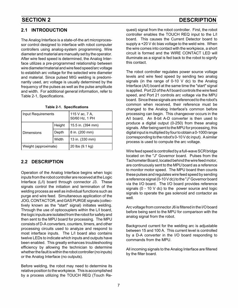
The Analog Interface is a state-of-the art microproces-sor control designed to interface with robot computercontrollers using analog-system programming. Wirediameter and material are manually set by the operator.After wire feed speed is determined, the Analog Inter-face utilizes a pre-programmed relationship betweenwire diameter/material and wire feed speed/arc voltageto establish arc voltage for the selected wire diameterand material. Since pulsed MIG welding is predomi-nantly used, arc voltage is usually determined by thefrequency of the pulses as well as the pulse amplitudeand width. For additional general information, refer toTable 2-1, Specifications.
Table 2-1. Specifications
Input Requirements 115 V ac, 7 A,50/60 Hz, 1 PH
Dimensions
Height 15.5 in. (394 mm)
Depth 8 in. (200 mm)
Width 13 in. (330 mm)
Weight (approximate) 20 lbs (9.1 kg)
2.2 DESCRIPTION
Operation of the Analog Interface begins when logicinputs from the robot controller are received at the LogicInterface (L/I) board through connector J3. Thesesignals control the initiation and termination of thewelding process as well as individual functions such aspurge and wire feed. Simultaneous application of theJOG, CONTACTOR, and GAS PURGE signals (collec-tively known as the "start" signal) initiates welding.Through the use of optocouplers within the L/I board,the logic inputs are isolated from the robot for safety andthen sent to the MPU board for processing. The MPUconsists of D-A converters, counters, timers, and otherprocessing circuits used to analyze and respond tomost interface inputs. The L/I board also containstwelve LEDs to indicate which inputs and outputs havebeen enabled. This greatly enhances troubleshootingefficiency by allowing the technician to determinewhether the fault is within the robot controller (no inputs)or the Analog Interface (no outputs).
Before welding, the robot may need to determine itsrelative position to the workpiece. This is accomplishedby a process utilizing the TOUCH REQ (Touch Re-
quest) signal from the robot controller. First, the robotcontroller enables the TOUCH REQ input to the L/Iboard. This causes the Current Detector board tosupply a +20 V dc bias voltage to the weld wire. Whenthe wire comes into contact with the workpiece, a shortcircuit is formed and the WIRE CONTACT LED willilluminate as a signal is fed back to the robot to signifythis contact.
The robot controller regulates power source voltagelevels and wire feed speed by sending two analogsignals (in the range of 0-10 V dc) to the AnalogInterface (A/I) board at the same time the "start" signalis applied. Port 22 of the A/I board controls the wire feedspeed, and Port 21 controls arc voltage via the MPUboard. Since these signals are referenced to the robot'scommon when received, their reference must bechanged to the Analog Interface's common beforeprocessing can begin. This changeover occurs in theA/I board. An 8-bit A-D converter is then used toproduce a digital output (0-250) from these analogsignals. After being sent to the MPU for processing, thisdigital input is multiplied by four to obtain a 0-1000 range(corresponding to the robot's 0-10 V dc input). A similarprocess is used to compute the arc voltage.
Wire feed speed is controlled by a full-wave SCR bridgelocated on the "J" Governor board. Pulses from theTachometer Board, located behind the wire feed motor,are continuously sent to the MPU board as a referenceto monitor motor speed. The MPU board then countsthese pulses and regulates wire feed speed by sendinga reference signal (0-10 V dc) to the "J" Governor boardvia the I/O board. The I/O board provides referencesignals (0 - 10 V dc) to the power source and logicsignals to operate the gas solenoid and contactor aswell.
Arc voltage from connector J6 is filtered in the I/O boardbefore being sent to the MPU for comparison with theanalog signal from the robot.
Background current for the welding arc is adjustablebetween 15 and 100 A. This current level is controlledby a D-A converter in the I/O board responding tocommands from the MPU.
All incoming signals to the Analog Interface are filteredby the filter board.

SECTION 3 EQUIPMENT
8
3.1 EQUIPMENT REQUIRED
A. Analog Interface ........................................ 34380
B. EH-10A Digital Welding Head (20-999 ipm). Eachmodel includes motor w/gear box, accessory sup-port and tach feedback unit1. EH-10AD Plug on Housing .......... 05580015352. Motor Ext. Cable, 25-ft ........................ 9968083. Motor Ext. Cable, 3-ft, ......................... 0001074. Accessory Support, 2-Roll Drive ...........49V515. Accessory Support, 4-Roll Drive ......... 6002166. Insulator Ring ....................................... 60N90
C. Feed rolls, outlet guides and other wire feed acces-sories for wire sizes and types that will be used.(See Table 3-1; Feed Rolls and Outlet Guides)
D. DIGIPULSE 450 Power Source or other suitablepower source
E. A control cable (J1-welding control to power sourcecable):1. 30-ft, 19-cond w/19-pin Amphenols ....... 307802. 60-ft, 19-cond w/19-pin Amphenols ....... 307813. 6-ft, 19-cond w/19-pin Amphenols......... 30686
F. A robot torch and accessories with capacity ratedfor your application.
G. Gas control equipment:1. R-5007 inert gas regulator/flowmeter . 9981242. R-5008 CO2 regulator/flowmeter ........ 9981253. 12.5-ft standard duty gas hose ............40V774. 25-ft standard duty gas hose ...............34V385. 12.5 ft heavy duty gas hose ................. 194166. 25-ft heavy duty gas hose .................... 19415
(use heavy duty hose for CO2 gas)7. Gas Hose Coupler .............................. 11N17
H. When using a water cooled torch, some of thefollowing items may be required to supply and drainthe cooling water:1. 12.5 ft water hose ................................40V762. 25-ft water hose ................................. 4061963. Water Hose Coupling ......................... 11N184. Water Adaptor, connects 5/8-18 (LH) hose to
1/4 NTP hose ..................................... 11N16
I. Voltage pickup lead (J6-Interface Control to torch);provides accurate arc voltage feedback to theControl, 25-ft, 1-cond. cable ...................... 34070
J. Plumbing box:1. Paddle wheel flow switch w/flow sight indicator ............................................... 341582. Standard flow switch ............................ 34159
K. Plumbing box control cable (J4-Interface to plumb-ing box; 3-ft, 6-cond) ................................. 34199
25-ft., 6-cond. ................................ 34845
L. Wire Inlet Guide (provided in Accessory Pkg. P/N504245) .................................................... 11N53
Table 3-1. Feed Rolls and Outlet Guides
Wire SizeIn (mm)
Two Roll DriveFeed Roll
Four Roll DriveFeed Roll Kit*
OutletGuide
Soft
.035 (.9)3/64 (1.2)1/16 (1.6)
2075304(U)2075301(U)+2075298
999321(U)999322(U)999323(U)
29N13**29N13**29N13**
Hard
.035 (.9)
.045 (1.2)
.052 (1.3)1/16 (1.6)
2075303(V)2075302(V)2075330(V)2075299(V)
999326(V)999327(V)999328(V)999329(V)
99386039N1539N1539N15
Cored Hard
.035 (.9)
.045 (1.2)
.052 (1.3)1/16 (1.6)
19761 (Serr.)19761 (Serr.)2075261 (Serr.)2075261 (Serr.)
999330 (Serr.)999331 (Serr.)999332 (Serr.)
99386039N1539N1539N15
U = U-groove V = V-groove Serr. = serrated
*Includes a center wire guide and 2 upper and 2 lowerfeed rolls.
**Requires outlet guide insert as follows:For .035 wire use 993902.For 3/64 wire use 05N57.For 1/16 wire use 12N57.
+Recommend U-Groove Pressure Roll 2075346 beused.

SECTION 3 EQUIPMENT
9
3.2 OPTIONAL ACCESSORIES
The following may be utilized to enhance performanceof the Analog Interface:
Torch Saver II; flow switch plus water filter assembledto protect water cooled torch against coolant loss,3/8 gpm .....................................................40V51
Torch Coolant Recirculator;WC-5B, 115 V ac, 60 Hz ........................... 19947WC-8B vertical, 115 V ac, 60 Hz, upright .. 30743
Wire Straightener; 3-roll adjustable ...............34V74
Digital Ammeter Kit ....................................... 34560
Wire Wiper Accessory, effectively cleans and lubri-cates wire:Felt Wiper, pkg. of 10 .............................. 598537Wiper Holder, mounts to outlet guide ...... 598764Wiper Holder, used w/opt. wirestraightener ............................................. 598763
Wire Support Equipment; mount to fixture to hold wirecoils or spools:Spindle Support Arm ............................... 634288Spindle Assembly, mounts to Arm .......... 948259Standard Wire Reel, hold 65 lbs coils ..... 995570H.D. Wire Reel, holds 65 lbs coils .............19V89Spool Enclosure Kit, covers12-in spools ............................................ 600240
SECTION 4 OPERATION
10
4.1 MOUNTING/CONNECTING EQUIP-MENT
For interconnection information on the Analog Interfacewith all required and/or optional accessories, see Fig-ures 4-1.
Since the operating controls for the Analog Interfaceare located on and behind the front cover, the boxshould be positioned within easy reach of the robotoperator. The control is designed to be mounted on avertical surface on or near the robot using the mountingholes provided.
Additional connections and/or adjustments can be foundas follows:
• Torch connections are provided in their re-spective instruction booklets.
• Installing feed rolls and wire spools, and ad-justing the accessory support cable can befound in the Digital Welding Head booklet F-12-873.
4.2 CONTROLS/INDICATORS
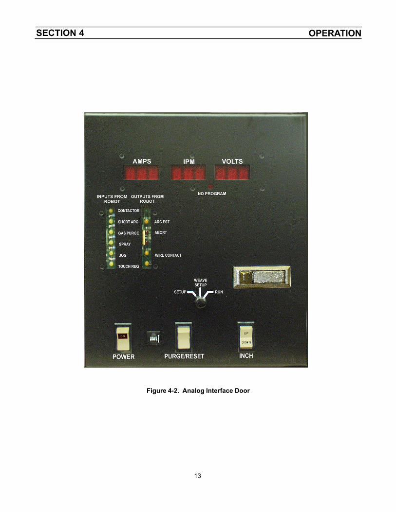
A. Front Panel Controls/Indicators (refer to Figure4-2).
1. POWER Switch. This switch applies 115 V acpower as indicated by light on switch.
2. PURGE/RESET Switch. A momentary "on"switch, this switch provides a dual functionwhen actuated:
a. Prior to starting the welding sequence, itactuates the gas solenoid and lets theoperator "purge" the shielding gas line ofthe torch.
b. After starting the welding sequence - if anabort "shutdown" condition occurs (indi-cated by flashing digital display), the Purge/Reset switch can be actuated and thecontrol will automatically "reset".
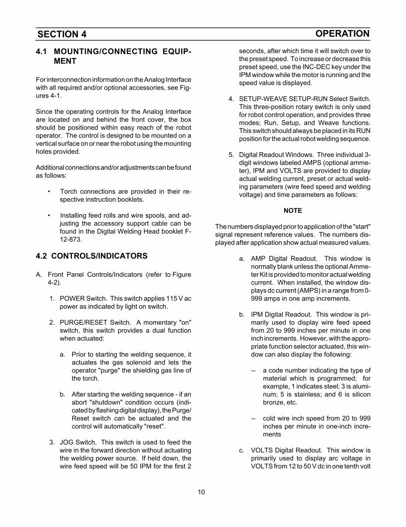
3. JOG Switch. This switch is used to feed thewire in the forward direction without actuatingthe welding power source. If held down, thewire feed speed will be 50 IPM for the first 2
seconds, after which time it will switch over tothe preset speed. To increase or decrease thispreset speed, use the INC-DEC key under theIPM window while the motor is running and thespeed value is displayed.
4. SETUP-WEAVE SETUP-RUN Select Switch.This three-position rotary switch is only usedfor robot control operation, and provides threemodes; Run, Setup, and Weave functions.This switch should always be placed in its RUNposition for the actual robot welding sequence.
5. Digital Readout Windows. Three individual 3-digit windows labeled AMPS (optional amme-ter), IPM and VOLTS are provided to displayactual welding current, preset or actual weld-ing parameters (wire feed speed and weldingvoltage) and time parameters as follows:
NOTE
The numbers displayed prior to application of the "start"signal represent reference values. The numbers dis-played after application show actual measured values.
a. AMP Digital Readout. This window isnormally blank unless the optional Amme-ter Kit is provided to monitor actual weldingcurrent. When installed, the window dis-plays dc current (AMPS) in a range from 0-999 amps in one amp increments.
b. IPM Digital Readout. This window is pri-marily used to display wire feed speedfrom 20 to 999 inches per minute in oneinch increments. However, with the appro-priate function selector actuated, this win-dow can also display the following:
-- a code number indicating the type ofmaterial which is programmed; forexample, 1 indicates steel; 3 is alumi-num; 5 is stainless; and 6 is siliconbronze, etc.
-- cold wire inch speed from 20 to 999inches per minute in one-inch incre-ments
c. VOLTS Digital Readout. This window isprimarily used to display arc voltage inVOLTS from 12 to 50 V dc in one tenth volt
SECTION 4 OPERATION
11
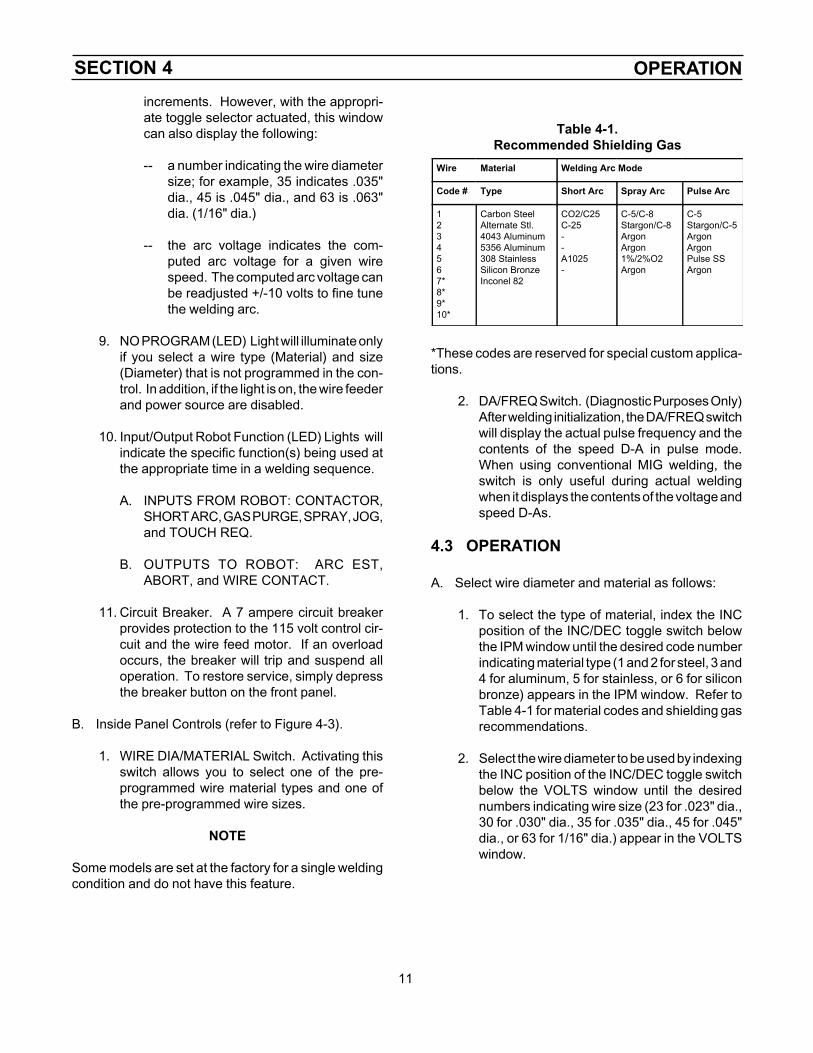
increments. However, with the appropri-ate toggle selector actuated, this windowcan also display the following:
-- a number indicating the wire diametersize; for example, 35 indicates .035"dia., 45 is .045" dia., and 63 is .063"dia. (1/16" dia.)
-- the arc voltage indicates the com-puted arc voltage for a given wirespeed. The computed arc voltage canbe readjusted +/-10 volts to fine tunethe welding arc.
9. NO PROGRAM (LED) Light will illuminate onlyif you select a wire type (Material) and size(Diameter) that is not programmed in the con-trol. In addition, if the light is on, the wire feederand power source are disabled.
10. Input/Output Robot Function (LED) Lights willindicate the specific function(s) being used atthe appropriate time in a welding sequence.
A. INPUTS FROM ROBOT: CONTACTOR,SHORT ARC, GAS PURGE, SPRAY, JOG,and TOUCH REQ.
B. OUTPUTS TO ROBOT: ARC EST,ABORT, and WIRE CONTACT.
11. Circuit Breaker. A 7 ampere circuit breakerprovides protection to the 115 volt control cir-cuit and the wire feed motor. If an overloadoccurs, the breaker will trip and suspend alloperation. To restore service, simply depressthe breaker button on the front panel.
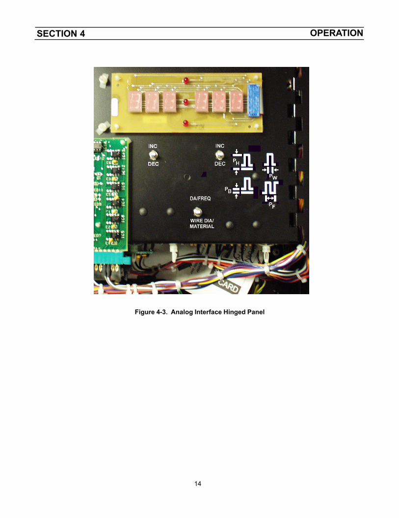
B. Inside Panel Controls (refer to Figure 4-3).
1. WIRE DIA/MATERIAL Switch. Activating thisswitch allows you to select one of the pre-programmed wire material types and one ofthe pre-programmed wire sizes.
NOTE
Some models are set at the factory for a single weldingcondition and do not have this feature.
Table 4-1.Recommended Shielding Gas
Wire Material Welding Arc Mode
Code # Type Short Arc Spray Arc Pulse Arc
1234567*8*9*10*
Carbon SteelAlternate Stl.4043 Aluminum5356 Aluminum308 StainlessSilicon BronzeInconel 82
CO2/C25C-25--A1025-
C-5/C-8Stargon/C-8ArgonArgon1%/2%O2Argon
C-5Stargon/C-5ArgonArgonPulse SSArgon
*These codes are reserved for special custom applica-tions.
2. DA/FREQ Switch. (Diagnostic Purposes Only)After welding initialization, the DA/FREQ switchwill display the actual pulse frequency and thecontents of the speed D-A in pulse mode.When using conventional MIG welding, theswitch is only useful during actual weldingwhen it displays the contents of the voltage andspeed D-As.
4.3 OPERATION
A. Select wire diameter and material as follows:
1. To select the type of material, index the INCposition of the INC/DEC toggle switch belowthe IPM window until the desired code numberindicating material type (1 and 2 for steel, 3 and4 for aluminum, 5 for stainless, or 6 for siliconbronze) appears in the IPM window. Refer toTable 4-1 for material codes and shielding gasrecommendations.
2. Select the wire diameter to be used by indexingthe INC position of the INC/DEC toggle switchbelow the VOLTS window until the desirednumbers indicating wire size (23 for .023" dia.,30 for .030" dia., 35 for .035" dia., 45 for .045"dia., or 63 for 1/16" dia.) appear in the VOLTSwindow.
SECTION 4 OPERATION
12
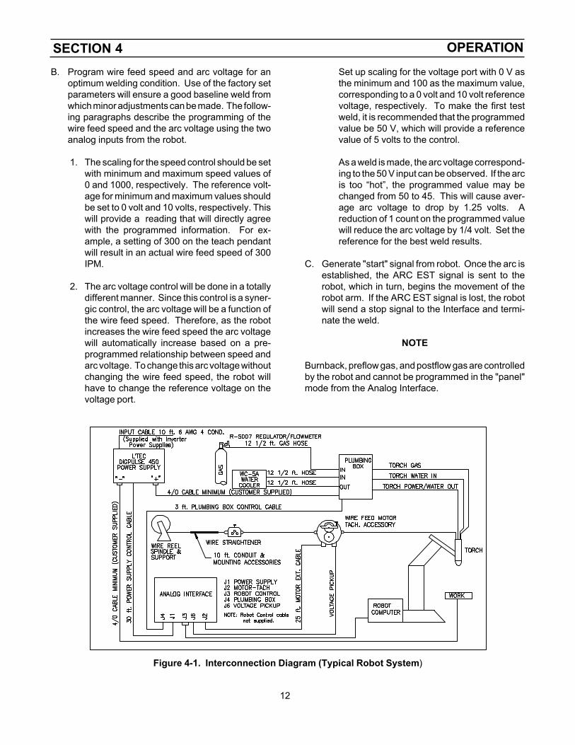
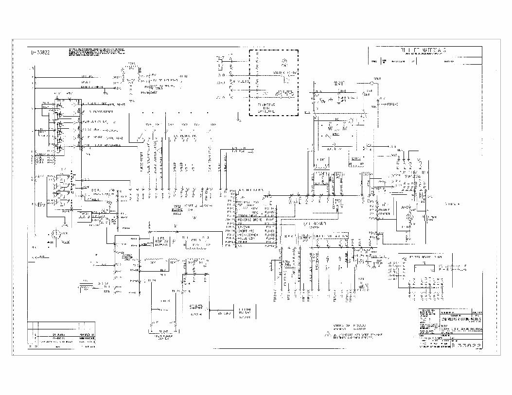
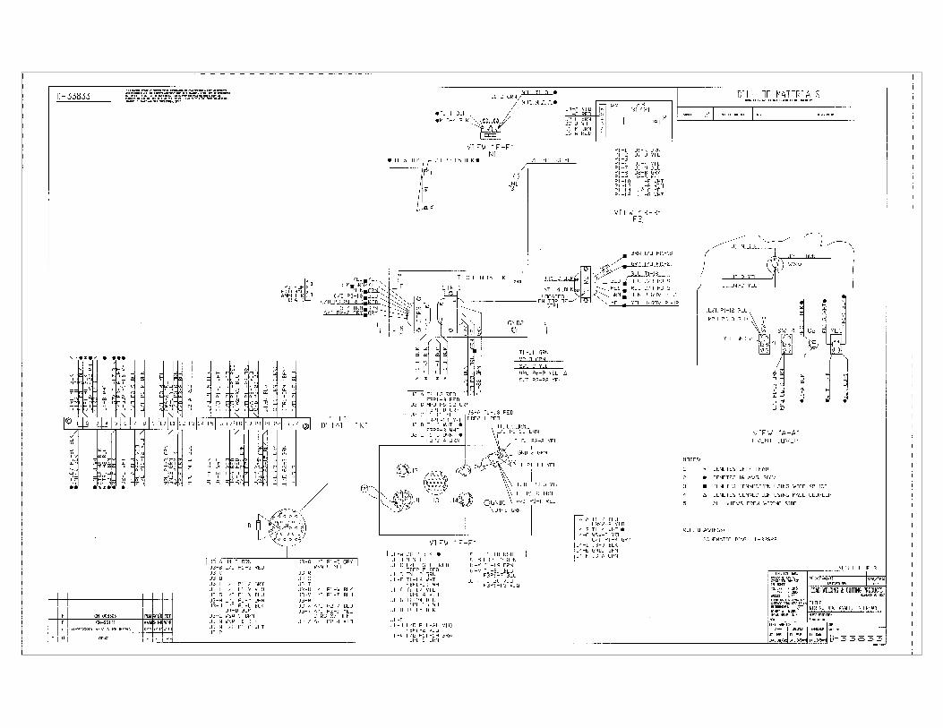
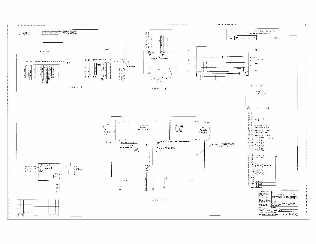
Figure 4-1. Interconnection Diagram (Typical Robot System)
B. Program wire feed speed and arc voltage for anoptimum welding condition. Use of the factory setparameters will ensure a good baseline weld fromwhich minor adjustments can be made. The follow-ing paragraphs describe the programming of thewire feed speed and the arc voltage using the twoanalog inputs from the robot.
1. The scaling for the speed control should be setwith minimum and maximum speed values of0 and 1000, respectively. The reference volt-age for minimum and maximum values shouldbe set to 0 volt and 10 volts, respectively. Thiswill provide a reading that will directly agreewith the programmed information. For ex-ample, a setting of 300 on the teach pendantwill result in an actual wire feed speed of 300IPM.
2. The arc voltage control will be done in a totallydifferent manner. Since this control is a syner-gic control, the arc voltage will be a function ofthe wire feed speed. Therefore, as the robotincreases the wire feed speed the arc voltagewill automatically increase based on a pre-programmed relationship between speed andarc voltage. To change this arc voltage withoutchanging the wire feed speed, the robot willhave to change the reference voltage on thevoltage port.
Set up scaling for the voltage port with 0 V asthe minimum and 100 as the maximum value,corresponding to a 0 volt and 10 volt referencevoltage, respectively. To make the first testweld, it is recommended that the programmedvalue be 50 V, which will provide a referencevalue of 5 volts to the control.
As a weld is made, the arc voltage correspond-ing to the 50 V input can be observed. If the arcis too “hot”, the programmed value may bechanged from 50 to 45. This will cause aver-age arc voltage to drop by 1.25 volts. Areduction of 1 count on the programmed valuewill reduce the arc voltage by 1/4 volt. Set thereference for the best weld results.
C. Generate "start" signal from robot. Once the arc isestablished, the ARC EST signal is sent to therobot, which in turn, begins the movement of therobot arm. If the ARC EST signal is lost, the robotwill send a stop signal to the Interface and termi-nate the weld.
NOTE
Burnback, preflow gas, and postflow gas are controlledby the robot and cannot be programmed in the "panel"mode from the Analog Interface.
SECTION 4 OPERATION
13
Figure 4-2. Analog Interface Door
SECTION 4 OPERATION
14
Figure 4-3. Analog Interface Hinged Panel
SECTION 5 TROUBLESHOOTING
15
5.1 INTRODUCTION
Listed below are a number of trouble symptoms, eachfollowed by the checks or action suggested to deter-mine the cause. Listing of checks and/or actions is in"most probable" order, but is not necessarily 100%exhaustive. Always follow this general rule: Do notreplace a printed circuit (PC) board until you have madeall the preceding checks. Always put the power switchin "off" position before removing or installing a PCboard. Take great care not to grasp or pull on compo-nents when removing a PC board. Always place boardson a "static free" surface. If a PC board is determinedto be the problem, check with your ESAB supplier for atrade-in or a new PC board. Supply the distributor withthe part number of the PC board (and pre-programnumber, as described in beginning of paragraph 5.2) aswell as the serial number of the wire feeder. Do notattempt to repair the PC board yourself. Warranty on aPC board will be null and void if repaired by customer oran unauthorized repair shop.
5.2 TROUBLESHOOTING GUIDE
Energize the power source and the Analog Interface.Immediately after the Interface is energized , a number(e.g. :3) will appear in the IPM readout window for only1 second. This number identifies the current program(E-PROMS) used in your Interface. When a programis changed, the new E-PROMS will automatically iden-tify the new program number being used. If a revisionis made to an existing program, a number .1, .2, .3, etc.indicating the numerical revision will also appear in theVOLTS readout window simultaneously.
A. Numeric display does not appear when poweris applied, or numbers are completely incor-rect.
1. Perform the following system reset to clearthe memory.
a. Turn off the Interface's 115 volt powerswitch.
b. Using one hand, hold both of the INC/DEC toggle switches in the INC posi-tion while reapplying 115-volt powerwith the other hand.
c. Almost immediately after the powerhas been turned on, release the INC/
DEC toggle switches to the neutral(spring-return center) position. TheIPM window will display 0 and the voltswindow will display a value greaterthan 0.
2. Make sure the LED display board harness/plug is plugged into the P5 receptacle onthe MPU board.
3. Check that 115 V ac is present acrossterminals T1-1 and T1-3, if present; powerswitch and circuit breaker are O.K..
4. Check for plus (+) 5 volts between termi-nals T1-10 and T1-12; if voltage is present,replace the MPU board. If voltage is notpresent, check the voltage regulator (VR).The voltage regulator is located on thebottom panel of the control box.
5. Check the input and output voltage of theregulator (VR).
a. The input should be approximately 11volts across capacitor on regulatorsocket. If voltage is not present, re-place I/O board.
b. If voltage is present, replace VR.
6. Check RAM battery voltage on I/O board(see Figure 5-1). If potential is less than3.5 volts, replace battery.
B. Numeric display is present but cannot be var-ied.
1. Change to "panel" mode by disconnectingJumper 1 (refer to Figure 6-3).
2. Set up wire feed speed and arc voltage(refer to Section 4).
3. Ensure the key wiring harness plug isproperly connected to receptacle P6 onthe MPU board.
4. If the above does not resolve the problem,replace the MPU board.
5. Reconnect Jumper 1.
SECTION 5 TROUBLESHOOTING
16
C. Correct numeric display is present, but wirefeed motor does not run.
1. Check to make sure all required (and/oroptional) accessories are correctly as-sembled as described in section 3.
2. Make sure the power source is connected,plug P2 and P3 are securely connected tothe I/O board, and then release the clapperarm (pressure roll) on the accessory sup-port assembly.
a. Operate the JOG switch. If motordoes not run; replace "J" Governor, I/O, and MPU boards respectively.
b. If motor feeds backwards due tomounting orientation of the motor, re-verse brown and white wires at T1-5and T1-6 on the lower side of terminalstrip T1.
c. If the motor inches, but does not runwhen a weld is attempted, check thecomposite "start" signal. If motor stilldoes not run, check if power supply isproviding open-circuit voltage of 72volts to the control. If OCV is not beingsupplied, motor will not run. Check thepower source for trouble.
d. Check that +/-12 V dc is provided fromthe power source on T1-16 and T1-17to T1-24 common, respectively.
D. Correct numeric display is present, but wirefeed motor runs at incorrect speed.
1. Check tachometer assembly mounted onthe end of EH-10 wire feed motor.
2. Make sure the tach disc is securely fas-tened to the motor shaft and that the strobemarkings are not scratched. Check thatthe disc is properly centered in the strobepickup on the PC board.
3. If all items in steps 1. and 2. are satisfac-tory, and motor speed is still incorrect,possible causes are as follows:
a. Defective MPU board.
b. Defective I/O board.
c. Defective "J" Governor board.
E. Numeric display is present, wire feed motorruns correctly, but robot does not weld.
1. If "start" signal LEDs (JOG, CONTACTOR,and GAS PURGE) are not illuminated,check interconnection between interface,power source, and robot controller.
2. Check for continuity in wires between in-terface and robot controller. If fault isoutside of connector J3, refer to robotmanual for further troubleshooting.
F. VOLTS display reads zero as robot attempts toweld.
NOTE
If VOLTS display reads zero when arc is present, STOPWELD IMMEDIATELY. Otherwise, torch damage mayresult.
1. Trace the voltage pickup wiring from thepower source to J6-A of the Interface.
2. If no reading is displayed, check for arcvoltage feed-back between terminals TP1and TP2 test points on the I/O PC board.This voltage signal should correspond tothat shown on the power supply voltmeter.
3. Check that the 5-pin plug is securely con-nected to the P3 receptacle on the MPUboard.
4. Remove the Current Detector board togain access to the P3 plug (harness) onthe MPU PC board. Disconnect plug P3from its MPU board socket and check for+/-12 volt power source output betweenplug pins P3-1 and P3-2 (for +12 V) andbetween plug pins P3-4 and P3-2 (for-12 V) respectively. If voltage is present,but still no reading, replace the MPU board.
G. CONTROL SHUTDOWN -- The Interface willflash the parameter (VOLTS or IPM) that can-not be maintained.
These symptoms may occur when the re-quested parameters cannot be maintained bythe Interface. Other possible reasons for ashutdown are as follows:
SECTION 5 TROUBLESHOOTING
17
e. If both of the preceding conditions(steps c. and d.) are satisfactory, butthe arc is still poor, the problem iseither in the interconnecting cable, thewelding setup, or in the power source.If possible, substitute a cable or powersource (known to be good) to checkout the possible problem; if these arenot available, check calibration of theI/O board by following the procedureslisted in paragraph 5.3 (DiagnosticMode).
f. If unit still aborts on volts after allprevious steps, refer to paragraph 5-4(Hot Start Adjustment).
H. Weld is poor, ropy, and erratic.
1. Check the MPU board's measurement ofthe arc voltage as follows:
a. Using a calibrated meter, measurepotential across TP1 and TP2 on the I/O board (see Figure 5-1).
b. Verify that this reading equals the volt-age shown in the VOLTS window.
2. If the MPU board is reading the arc voltageincorrectly, calibrate as follows:
a. Set switch SW1-1 on MPU board tothe ON position.
b. Connect an accurate meter betweenTP1 and TP2 on the I/O board tomeasure the arc voltage.
c. Strike an arc and adjust it for a stablecondition. While the arc is in progress,adjust potentiometer R23 on the MPUboard with a narrow blade screwdriveruntil the Interface reads the same asthe external meter.
d. Reset switch SW1-1 to the OFF posi-tion.
NOTE
SW1-1 must be reset to the OFF position beforewelding can occur.
1. IPM (speed) abort and possible causes:
a. Defective J-governor board.
b. Defective Tachometer board.
c. Defective I/O board.
d. Defective MPU board.
e. Initial "hot start" parameters incorrectlyset. Refer to paragraph 5.4 (Hot StartAdjustment).
Contact ESAB Group Engineering Service for furtherassistance (803-669-4411).
2. VOLTS (voltage) abort and possiblecauses: The source of this problem maybe located in the wire feeder or the powersource. To determine which, check thewire feeder as follows:
a. Set the wire feeder for synergic opera-tion in the pulse welding mode byoperating SW1-1 on Bank 1 of theMPU board (see Figure 5-2).
b. Set unit to the panel mode by discon-necting Jumper 1.
c. Using the robot to initiate a weld, mea-sure the potential between T1-15 (+)and T1-24 (control signal to the powersource). Note that as the arc voltagesetting is increased, the potential be-tween T1-15 and T1-24 also increases,and will range from 0 to 10 V dc. If itdoes not, replace the I/O and/or MPUboard. If the potential is present andresponding to the voltage change set-ting, continue with step d.
d. Now measure the control voltage, forthe background current, between T1-24 and pin J1-J of the amphenol con-nector. This measurement can betaken without striking an arc. Thepotential will be in a range from 1 to 2.5volts. If it is not, replace the I/O and/orMPU board. If the background poten-tial is present, continue with step e.
SECTION 5 TROUBLESHOOTING
18
I. Welds are okay in short arc and spray modebut poor in pulse mode.
-- Check calibration of the I/O board follow-ing the procedures listed in paragraph 5-3(Diagnostic Mode).
J. Analog Interface is not accurately respondingto robot commands (e.g. Robot requests 350IPM, but Interface displays 300 or 400 IPM).
-- Check calibration of A/I boards as follows:
1. Check for 5 volts on port 22 of the A/I boardand for a speed of 500 in the IPM window.If 500 IPM is not displayed, adjust R5(SPEED) on A/I board until 500 IPM isdisplayed (see Figure 5-3).
2. Set switch SW1-1 on MPU board to the ONposition. Check for 5 volts on port 21 of theA/I board and a display of 100 in theVOLTS window. If 100 VOLTS is notdisplayed, adjust R8 (VOLTAGE) on A/Iboard until 100 VOLTS is displayed (seeFigure 5-3). Reset SW1-1 to the OFFposition.
NOTE
SW1-1 must be reset to the OFF position beforewelding can occur.
5.3 DIAGNOSTIC MODE
Depress the WIRE DIA/MATERIAL key and hold theIPM INC/DEC key in its down position for 2.5 secondsuntil a zero (0) appears in the IPM window. (The 2.5seconds will prevent accidental zeroing of the Materialcode.)
Now release both keys. The display windows willchange to show a background current value (from 0 to100) in the IPM window, and a pulse height value (from0.1 to 10) in the VOLTS window. These numbers canbe changed by their respective INC/DEC switches.
To check the calibration of the I/O board, connect avoltmeter from T1-24 to T1-15 (positive). Provide startsignal from robot and check the measured voltageagainst the number displayed in the VOLTS window -they should both be the same (for example: for a settingof 5.0, the I/O board should be 5 V dc). If the measured
potential is different, the I/O board should either berecalibrated (by a qualified technician) by adjusting R54until reading agrees with preset value (should be doneat 5 volts), or the board should be replaced.
Next, enter a value of 40 in the IPM window. Check thepotential from T1-24(-) to pin J1-J of the Amphenolconnector for a reading of 2 V dc. If 2 +.1 V dc is notpresent, replace the I/O board. If all of these readingsare correct, check the power source by using the"calibration procedure" described in Inverter ControlBoard (ICB) Troubleshooting in the Power Supplymanual F-15-014.
5.4 HOT START ADJUSTMENT
The Analog Interface is preset at the factory to provideoptimum starting characteristics for most welding con-ditions. However, due to factors such as border lineparameters (for a given wire type and size), weldingtechnique, shielding gas, or wire feed speed, you mayhave to readjust the factory-set settings to provide a hotstart in which the initial starting voltage is slightly higherthan actual welding voltage (arc voltage) and the initialspeed is somewhat lower than the selected wire feedspeed desired. The hot start condition will be termi-nated after 0.3 seconds. The following procedureshould be used.
A. Program the welding condition you need in the IPM(wire feed speed) and VOLTS (arc voltage) win-dows, and fine-tune these parameters until youhave the welding arc desired - At this point do notconcern yourself with the "arc starts".
B. If after the welding condition is fine-tuned, but the"arc starts" are unsatisfactory, proceed as follows:
1. During an actual weld, actuate and hold theWIRE DIA/MATERIAL switch and observe thenumbers displayed in the IPM and VOLTSwindows.
2. For proper starts, the number in the IPM win-dow should be 105 to 115. If it is not, adjust theINC/DEC toggle (below the IPM window) untilthe displayed number reads about 110.
3. Similarly, the number in the VOLTS windowshould be in the range of 90 to 100. Again, if itis not, adjust the INC/DEC toggle (below theVOLTS window) until the displayed numberreads about 95.
SECTION 5 TROUBLESHOOTING
19
4. These adjustments should provide good arcstarts to a legitimate welding condition.
5. A good "rule-of-thumb" to follow whenever youset up a new welding condition and you expe-rience unstable starts, is to simply check thestart characteristic numbers (while welding) tomake sure they are within the ranges de-scribed in the preceding steps.
C. If you continue experiencing problems, refer to thebeginning of Section 5 for Troubleshooting proce-dures.
NOTE
Training and Troubleshooting Courses are available formaintenance and repair of this and other ESAB Groupequipment. For details, contact ESAB Welding &Cutting Products, P.O. Box 100545, Ebenezer Road,Florence, SC 29501-0545; Telephone (803) 669-4411.Attention: Technical Training Coordinator.
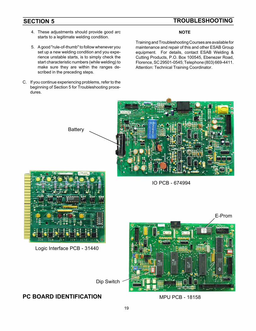
IO PCB - 674994
Battery
MPU PCB - 18158
Dip Switch
E-Prom
Logic Interface PCB - 31440
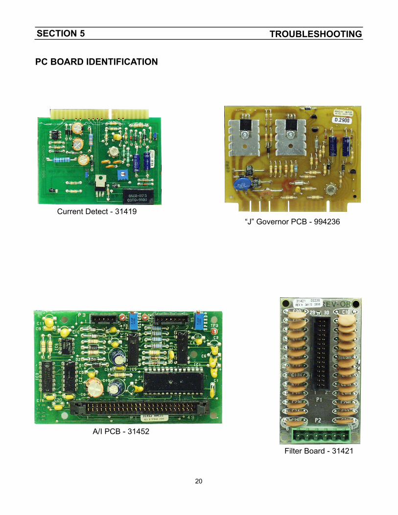
PC BOARD IDENTIFICATION
SECTION 5 TROUBLESHOOTING
20
Filter Board - 31421
“J” Governor PCB - 994236
A/I PCB - 31452
Current Detect - 31419
PC BOARD IDENTIFICATION

SECTION 6 REPLACEMENT PARTS
21
Replacement parts may be ordered from your ESABdistributor. Refer to the Communication Guide locatedon the last page of this manual for a list of customerservice phone numbers.
6.1 General
Replacement parts are illustrated on the followingfigures. When ordering replacement parts, order bypart number and part name, as listed. Always providethe series or serial number of the unit on which theparts will be used. The serial number is stamped onthe unit nameplate.
SECTION 6 REPLACEMENT PARTS
22
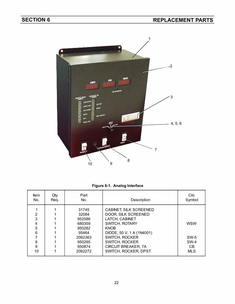
Figure 6-1. Analog Interface
1
2
3
4, 5, 6
810 9
7
ItemNo.
QtyReq.
PartNo. Description
Ckt.Symbol
12345678910
1111111111
317453208495258668035995028295464
2062363950295950874
2062272
CABINET, SILK SCREENEDDOOR, SILK SCREENEDLATCH, CABINETSWITCH, ROTARYKNOBDIODE, 50 V, 1 A (1N4001)SWITCH, ROCKERSWITCH, ROCKERCIRCUIT BREAKER, 7ASWITCH, ROCKER, DPST
WSW
SW-5SW-4CB
MLS
SECTION 6 REPLACEMENT PARTS
23
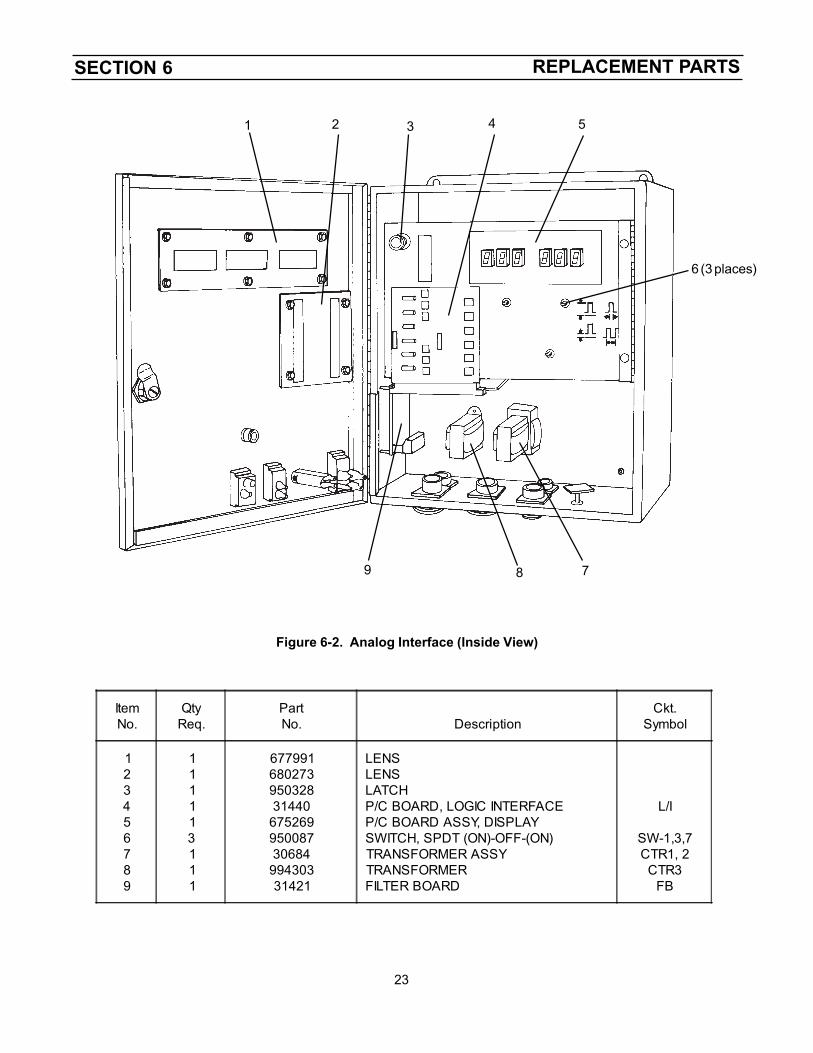
Figure 6-2. Analog Interface (Inside View)
1 2 3 4 5
6 (3 places)
789
ItemNo.
QtyReq.
PartNo. Description
Ckt.Symbol
123456789
111113111
677991680273950328314406752699500873068499430331421
LENSLENSLATCHP/C BOARD, LOGIC INTERFACEP/C BOARD ASSY, DISPLAYSWITCH, SPDT (ON)-OFF-(ON)TRANSFORMER ASSYTRANSFORMERFILTER BOARD
L/I
SW-1,3,7CTR1, 2CTR3
FB
SECTION 6 REPLACEMENT PARTS
24
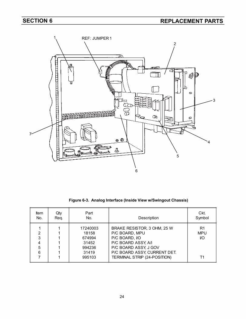
Figure 6-3. Analog Interface (Inside View w/Swingout Chassis)
12
3
4
5
6
7
REF: JUMPER 1
ItemNo.
QtyReq.
PartNo. Description
Ckt.Symbol
1234567
1111111
1724000318158
6749943145299423631419995103
BRAKE RESISTOR, 3 OHM, 25 WP/C BOARD, MPUP/C BOARD, I/OP/C BOARD ASSY, A/IP/C BOARD ASSY, J GOVP/C BOARD ASSY, CURRENT DET.TERMINAL STRIP (24-POSITION)
R1MPUI/O
T1
SECTION 6 REPLACEMENT PARTS
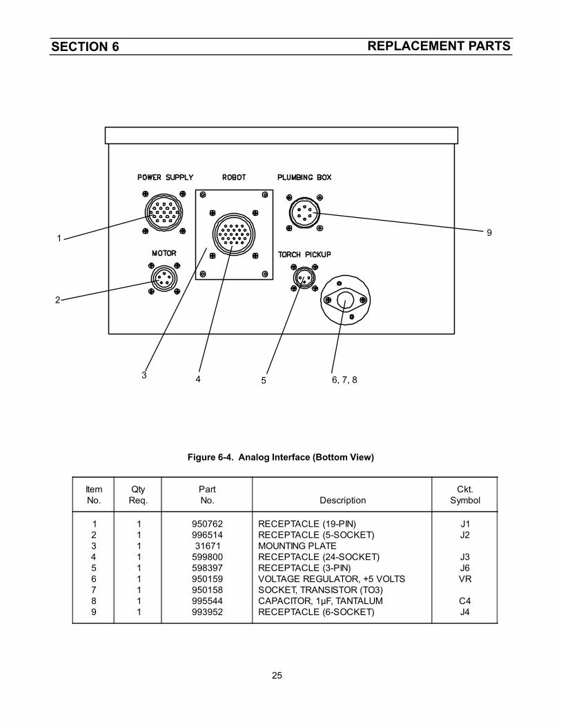
25
Figure 6-4. Analog Interface (Bottom View)
1
2
4 5 6, 7, 8
9
3
ItemNo.
QtyReq.
PartNo. Description
Ckt.Symbol
123456789
111111111
95076299651431671
599800598397950159950158995544993952
RECEPTACLE (19-PIN)RECEPTACLE (5-SOCKET)MOUNTING PLATERECEPTACLE (24-SOCKET)RECEPTACLE (3-PIN)VOLTAGE REGULATOR, +5 VOLTSSOCKET, TRANSISTOR (TO3)CAPACITOR, 1µF, TANTALUMRECEPTACLE (6-SOCKET)
J1J2
J3J6VR
C4J4

SECTION 6 REPLACEMENT PARTS
30
NOTE

SECTION 6 REPLACEMENT PARTS
31
NOTE

ESAB Welding & Cutting ProductsPO Box 100545 Florence SC 29501-0545
F-15-151-B 9/2000 Printed in U.S.A.
IF YOU DO NOT KNOW WHOM TO CALL
Telephone: (800) ESAB-123/ Fax: (843) 664-4452/ Web:http://www.esab.com
Hours: 7:30 AM to 5:00 PM EST
A. CUSTOMER SERVICE QUESTIONS:Order Entry Product Availability Pricing DeliveryOrder Changes Saleable Goods Returns Shipping Information
Eastern Distribution Center Telephone: (800)362-7080 / Fax: (800) 634-7548
Central Distribution Center Telephone: (800)783-5360 / Fax: (800) 783-5362
Western Distribution Center Telephone: (800) 235-4012/ Fax: (888) 586-4670
B. ENGINEERING SERVICE: Telephone: (843) 664-4416 / Fax : (800) 446-5693Welding Equipment Troubleshooting Hours: 7:30 AM to 5:00 PM ESTWarranty Returns Authorized Repair Stations
C. TECHNICAL SERVICE: Telephone: (800) ESAB-123/ Fax: (843) 664-4452Part Numbers Technical Applications Hours: 8:00 AM to 5:00 PM ESTPerformance Features Technical Specifications Equipment Recommendations
D. LITERATURE REQUESTS: Telephone: (843) 664-5562 / Fax: (843) 664-5548Hours: 7:30 AM to 4:00 PM EST
E. WELDING EQUIPMENT REPAIRS: Telephone: (843) 664-4487 / Fax: (843) 664-5557Repair Estimates Repair Status Hours: 7:30 AM to 3:30 PM EST
F. WELDING EQUIPMENT TRAINING:Telephone: (843)664-4428 / Fax: (843) 679-5864Training School Information and Registrations Hours: 7:30 AM to 4:00 PM EST
G. WELDING PROCESS ASSISTANCE:Telephone: (800) ESAB-123 / Fax: (843) 664-4454 Hours: 7:30 AM to 4:00 PM EST
H. TECHNICAL ASST. CONSUMABLES:Telephone : (800) 933-7070 Hours: 7:30 AM to 5:00 PM EST
ESAB Welding & Cutting Products, Florence, SC Welding EquipmentCOMMUNICATION GUIDE - CUSTOMER SERVICES