Historian to Historian Interface Installation and Configuration Guide

PI Interface for ABB IMS Advant
Version 5.82.0.xRevision C

OSIsoft, LLC777 Davis St., Suite 250San Leandro, CA 94577 USATel: (01) 510-297-5800Fax: (01) 510-357-8136Web: http://www.osisoft.com
OSIsoft Australia • Perth, AustraliaOSIsoft Europe GmbH • Frankfurt, GermanyOSIsoft Asia Pte Ltd. • SingaporeOSIsoft Canada ULC • Montreal & Calgary, CanadaOSIsoft, LLC Representative Office • Shanghai, People’s Republic of ChinaOSIsoft Japan KK • Tokyo, JapanOSIsoft Mexico S. De R.L. De C.V. • Mexico City, MexicoOSIsoft do Brasil Sistemas Ltda. • Sao Paulo, BrazilOSIsoft France EURL • Paris, France
PI Interface for ABB IMS AdvantCopyright: © 2003-2013 OSIsoft, LLC. All rights reserved.No part of this publication may be reproduced, stored in a retrieval system, or transmitted, in any form or by any means, mechanical, photocopying, recording, or otherwise, without the prior written permission of OSIsoft, LLC.
OSIsoft, the OSIsoft logo and logotype, PI Analytics, PI ProcessBook, PI DataLink, ProcessPoint, PI Asset Framework(PI-AF), IT Monitor, MCN Health Monitor, PI System, PI ActiveView, PI ACE, PI AlarmView, PI BatchView, PI Coresight, PI Data Services, PI Event Frames, PI Manual Logger, PI ProfileView, PI WebParts, ProTRAQ, RLINK, RtAnalytics, RtBaseline, RtPortal, RtPM, RtReports and RtWebParts are all trademarks of OSIsoft, LLC. All other trademarks or trade names used herein are the property of their respective owners.
U.S. GOVERNMENT RIGHTSUse, duplication or disclosure by the U.S. Government is subject to restrictions set forth in the OSIsoft, LLC license agreement and as provided in DFARS 227.7202, DFARS 252.227-7013, FAR 12.212, FAR 52.227, as applicable. OSIsoft, LLC.
Published: 10/2013

Table of Contents
Chapter 1. Introduction...................................................................................................1Reference Manuals............................................................................................2Supported Operating Systems...........................................................................2Supported Features...........................................................................................4Diagram of Hardware Connection......................................................................7
Chapter 2. Principles of Operation................................................................................9Data Acquisition.................................................................................................9
Input.........................................................................................................9Quality Check for Selected Attributes....................................................10Output....................................................................................................11Connection to the PI Server...................................................................12Connection to the DCS..........................................................................12Timestamps...........................................................................................13Sign-up for Updates...............................................................................13
Supported Object Types..................................................................................14Basic Objects.........................................................................................14MOD 300 Process Objects....................................................................14Other Object Types (Selection)..............................................................14
Transfer Methods.............................................................................................15ABB Attribute Data Types................................................................................15Events – Recommended for ABB Master Only................................................16
Chapter 3. Installation Checklist..................................................................................17Data Collection Steps.......................................................................................17Interface Diagnostics........................................................................................18Advanced Interface Features...........................................................................18
Chapter 4. Interface Installation on Windows.............................................................19Naming Conventions and Requirements..........................................................19Interface Directories.........................................................................................20
PIHOME Directory Tree.........................................................................20Interface Installation Directory...............................................................20
Interface Installation Procedure.......................................................................20Installing Interface as a Windows Service........................................................20Installing Interface Service with PI Interface Configuration Utility....................21
Service Configuration............................................................................21Installing Interface Service Manually................................................................23
Chapter 5. Interface Installation on UNIX....................................................................25Naming Conventions and Requirements..........................................................26Interface Directories.........................................................................................26
PIHOME Directory.................................................................................26
PI Interface for ABB IMS Advant

Interface Installation Directory...............................................................26Definition of Environment Variables.......................................................27
Interface Installation Procedure.......................................................................28Interface Upgrade............................................................................................30Installing/Upgrading from CD-ROM or a Downloaded File...............................30Interface Files for HP-UX.................................................................................31Additional Files after Link.................................................................................31Linking the PI Interface for ABB Advant...........................................................31Linking the Interface Control Program..............................................................32HP-UX Ownership of Interface Files................................................................32
Chapter 6. Digital States...............................................................................................33
Chapter 7. PointSource.................................................................................................35
Chapter 8. PI Point Configuration................................................................................37Point Attributes.................................................................................................37
Tag........................................................................................................37PointSource...........................................................................................38PointType...............................................................................................38Location1...............................................................................................38Location2...............................................................................................38Location3...............................................................................................38Location4...............................................................................................39Location5...............................................................................................39InstrumentTag........................................................................................39ExDesc..................................................................................................40Scan......................................................................................................41Shutdown...............................................................................................41
Output Points...................................................................................................41Trigger Method 1 (Recommended)........................................................42Trigger Method 2...................................................................................43
Hints for Point Configuration............................................................................43HP-UX....................................................................................................43Increasing Shared Memory Size on HP-UX...........................................44Increasing Shared Memory Size on Windows Systems.........................45How to Retrieve a List of all Available Objects.......................................45
Chapter 9. Startup Command File...............................................................................47Configuring the Interface with PI ICU...............................................................47
ABBims Interface Page..........................................................................49Command-line Parameters..............................................................................53Sample abbimspi.bat File.................................................................................63Sample Interface Startup Files for HP-UX........................................................64
On Demand...........................................................................................64On Event..........................................................................................................65Cyclic...............................................................................................................66
Chapter 10. UniInt Failover Configuration................................................................69Introduction......................................................................................................69
Quick Overview......................................................................................70Synchronization through a Shared File (Phase 2)............................................71
PI Interface for ABB IMS Advant

Configuring Synchronization through a Shared File (Phase 2)........................72Configuring UniInt Failover through a Shared File (Phase 2)...........................75
Start-Up Parameters..............................................................................75Failover Control Points..........................................................................77PI Tags..................................................................................................78
Detailed Explanation of Synchronization through a Shared File (Phase 2)......82Steady State Operation..........................................................................83
Failover Configuration Using PI ICU................................................................85Create the Interface Instance with PI ICU........................................................85Configuring the UniInt Failover Startup Parameters with PI ICU......................86Creating the Failover State Digital State Set....................................................86
Using the PI ICU Utility to create Digital State Set.................................87Using the PI SMT 3 Utility to create Digital State Set............................87
Creating the UniInt Failover Control and Failover State Tags (Phase 2)..........90
Chapter 11. Interface Node Clock..............................................................................91Windows..........................................................................................................91HP-UX..............................................................................................................92
Chapter 12. Security....................................................................................................93Windows and UNIX..........................................................................................93
Chapter 13. Starting / Stopping the Interface on Windows.....................................95Starting Interface as a Service.........................................................................95Stopping Interface Running as a Service.........................................................95
Chapter 14. Starting / Stopping the Interface on UNIX............................................97Command-line Syntax for Background Processes...........................................97Terminating Background Processes................................................................98Anomalous Background Job Termination........................................................98
Chapter 15. Buffering..................................................................................................99Which Buffering Application to Use..................................................................99How Buffering Works.....................................................................................100Buffering and PI Server Security....................................................................100Enabling Buffering on an Interface Node with the ICU...................................101
Choose Buffer Type.............................................................................101Buffering Settings................................................................................102Buffered Servers..................................................................................104Installing Buffering as a Service...........................................................107
Chapter 16. Interface Diagnostics Configuration...................................................111Scan Class Performance Points....................................................................111Configuring Performance Points on UNIX......................................................114Performance Counters Points........................................................................114
Performance Counters.........................................................................116Performance Counters for both (_Total) and (Scan Class x)...............116Performance Counters for (_Total) only...............................................117Performance Counters for (Scan Class x) only....................................120
Interface Health Monitoring Points.................................................................121PI Interface for ABB IMS Advant

Table of Contents
I/O Rate Point................................................................................................127Configuring I/O Rate Tags On UNIX..............................................................129
Configuring PI Point on the PI Server..................................................129Configuration on the Interface Node....................................................130
Interface Status Point.....................................................................................130
Appendix A. Error and Informational Messages....................................................133Message Logs................................................................................................133Messages.......................................................................................................133System Errors and PI Errors..........................................................................133UniInt Failover Specific Error Messages........................................................134
Informational........................................................................................134Errors (Phase 1 & 2)............................................................................135Errors (Phase 2)..................................................................................136
Appendix B. PI SDK Options....................................................................................137
Appendix C. Hints for PI System Manager..............................................................139Automatic Interface Start on HP-UX System Startup via ABB’s Process
Supervision...................................................................................................................139Graceful Interface Stop on System Shutdown...............................................140Starting the Interface when the PI API is Started (HP-UX).............................141Stopping the Interface When the PI API is Stopped (HP-UX)........................141Automatic Interface Start on Windows – Practical Experiences.....................142Increasing Number of Interfaces per AEH on Windows.................................143
Appendix D. Interface Control Program – HP-UX only..........................................145
Appendix E. Achieving Better Interface Performance...........................................147Use More Interface Copies............................................................................147Use Scan Class Offsets.................................................................................147Use a Separate Interface Copy for a Fast Scan Class...................................147Consider the Transfer Method “On Event” (ABB Master only).......................147
Appendix F. Test Environment................................................................................149IMS 2.0...........................................................................................................149AEH 2.1..........................................................................................................149AEH 2.2..........................................................................................................150
Appendix G. Attribute Lists via getObj...................................................................151
Appendix H. Mounting a Windows CD ROM on an HP-UX Advant Station..........169
Appendix I. Terminology..........................................................................................173
Appendix J. Technical Support and Resources.....................................................177Before You Call or Write for Help.........................................................177Help Desk and Telephone Support......................................................177Search Support....................................................................................178Email-based Technical Support...........................................................178

Online Technical Support.....................................................................178Remote Access....................................................................................179On-site Service....................................................................................179Knowledge Center...............................................................................179Upgrades.............................................................................................179OSIsoft Virtual Campus (vCampus).....................................................180
Appendix K. Revision History..................................................................................181
PI Interface for ABB IMS Advant

Chapter 1. Introduction
The PI Interface for ABB IMS/AEH Advant Station (referred to as PI Interface for ABB Advant in this document) provides the read/write transfer of data between an ABB Master or ABB MOD 300 process control system and the PI System using the AdvaInform UserAPI.
The PI Interface for ABB Advant uses the capabilities of the AdvaInform UserAPI contained in IMS Software version 1.2. The interface is also compatible with IMS Software version 1.3. It uses the bciDoRequest call.
The AdvaInform UserAPI is now included in the ABB Advant Enterprise Historian Select Package. Previously the AdvaInform UserAPI was included with the ABB Advant Enterprise Historian. The Select package does not contain the ABB Enterprise Historian but is sufficient to run the interface.
Note on HP-UX: There are limits to the number of points and events per second that can be retrieved from a single Advant station. An Advant station with an RTA card that contains 8 Mbytes of RAM will allow between 4000 – 6000 tags to be retrieved from the control system. The expected throughput for a machine with 64 Mbytes of RAM is approximately 300 calls per second.
The AdvaInform User API provides functions for data transfer between an ABB Advant Station based on HP-UX or Windows systems and a connected ABB Master (ASEA Masterpiece) or a MOD 300 DCS.
Note: The PI Interface for ABB Advant accesses the ABB objects directly in the DCS through the AdvaInform UserAPI. No local copies of the Process Objects are required on the Advant Station. The interface does not use the Oracle tables on the Advant Station
Note: The value of [PIHOME] variable for the 32-bit interface will depend on whether the interface is being installed on a 32-bit operating system (C:\Program Files\PIPC) or a 64-bit operating system (C:\Program Files (x86)\PIPC).
The value of [PIHOME64] variable for a 64-bit interface will be C:\Program Files\PIPC on the 64-bit operating system.
In this documentation [PIHOME] will be used to represent the value for either [PIHOME] or [PIHOME64]. The value of [PIHOME] is the directory which is the common location for PI client applications.
Note: Throughout this manual there are references to where messages are written by the interface which is the PIPC.log. This interface has been built against a UniInt
PI Interface for ABB IMS Advant

version (4.5.0.59 and later) which now writes all its messages to the local PI Message log.
Please note that any place in this manual where it references PIPC.log should now refer to the local PI message log. Please see the document UniInt Interface Message Logging.docx in the %PIHOME%\Interfaces\UniInt directory for more details on how to access these messages.
Reference Manuals
OSIsoft PI Server manuals
PI API Installation Instructions manual
UniInt Interface User Manual
Vendor ABB Master AdvaInform Basic Functions User’s Guide Part 1 and 2
ABB Master AdvaInform Object Handling User’s Guide
ABB Master AdvaInform Object Types Reference Manual
Advant OCS with MOD 300 Software AdvaInform Object Types Reference Manual
ABB Master Advant Station 500 Series Information Management Station User’s Guide
ABB Master Advant Station 500 Information Management Station SW*1.1/2 Release Description
AdvaInform Basic Functions Release Notes
Advant Enterprise Historian for Windows NT
Advant MES Advant Enterprise Historian for Windows NT Administrator's Guide
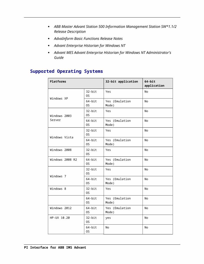
Supported Operating Systems
Platforms 32-bit application 64-bit application
Windows XP32-bit OS Yes No
64-bit OS Yes (Emulation Mode) No
Windows 2003 Server32-bit OS Yes No
64-bit OS Yes (Emulation Mode) No
Windows Vista32-bit OS Yes No
64-bit OS Yes (Emulation Mode) No
Windows 2008 32-bit OS Yes No
Windows 2008 R2 64-bit OS Yes (Emulation Mode) No
Windows 732-bit OS Yes No
64-bit OS Yes (Emulation Mode) No
PI Interface for ABB IMS Advant

Platforms 32-bit application 64-bit application
Windows 8 32-bit OS Yes No
64-bit OS Yes (Emulation Mode) No
Windows 2012 64-bit OS Yes (Emulation Mode) No
HP-UX 10.20 32-bit OS yes No
64-bit OS No No
The interface is designed to run on the above-mentioned UNIX and Microsoft Windows operating systems. Because it is dependent on vendor software, newer platforms may not yet be supported.
The PI Interface for ABB Advant runs on the Advant Station (IMS or AEH)
The PI Interface for ABB Advant cannot run on an Engineering Station (ES)
The PI Interface for ABB Advant cannot run on an Operator Station (OS)
The Advant Station serves as a PI interface node. It is not recommended to run the PI Server on the same system.
The following environments are supported:
IMS 2.0 under HP-UX 10.20AEH 2.0 under HP-UX 10.20AEH 2.1 under HP-UX 10.20AEH 2.2 under HP-UX 10.20AEH 3.2 under Windows 2000AEH 4+ under Windows 2003AEH 4+ under Windows Xp
Note: Execution of this interface is supported on Windows 2000 operating systems. However, the execution of its self-extracting setup kit is not supported. To install this interface on a Windows 2000 system, allow the executable setup kit to unzip; navigate to the unzip folder; and then, directly run the interface MSI file (abbimspi_5.82.0.X.msi) followed by the ICU control MSI (abbimspi_ICU_5.x.x.x.msi) file.
The AdvaInform UserAPI must be installed on the IMS/AEH.
Note that "2.x" for AEH on HP-UX and "3.x" for AEH on Windows is an ABB naming convention used to differentiate between OS platforms by the version number. It's actually the same software generation.
The PI Interface for ABB Advant was originally developed to run on an Information Management Station (IMS) on HP-UX. Starting with version 4.0 of the interface it can also run on a Windows PC running the ABB Advant Enterprise Historian (AEH).
Version 4.x and greater of the interface does not run on HP-UX 9.05 and therefore no longer supports IMS 1.x.
Please contact OSIsoft Technical Support for more information.
PI Interface for ABB IMS Advant
Introduction
Supported Features
Feature Support
Interface Part Number PI-IN-ABB-ADV-HPUXPI-IN-ABB-ADV-NTI
Auto Creates PI Points No
Point Builder Utility No
ICU Control Yes
PI Point Types Float16 / Float32 / Float64 / Int16 / Int32 / Digital / String
Sub-second Timestamps No
Sub-second Scan Classes Yes
Automatically Incorporates PI Point Attribute Changes
Yes
Exception Reporting Yes
Outputs from PI Yes
Inputs to PI: ‘On Demand’ (Scan-Based),‘Cyclic’ (Cyclically initiated by DCS)‘On Event’ (Events sent by the DCS)
Supports Questionable Bit No
Supports Multi-character PointSource Yes
Maximum Point Count See ABB limit in the Introduction
* Uses PI SDK No
PINet String Support No
* Source of Timestamps Local time on the Advant Station or PI Server time
History Recovery No
* UniInt-based* Disconnected Startup* SetDeviceStatus
YesYesYes
* Failover UniInt Failover (Phase 2, Cold, Warm and Hot)
* Vendor Software Required on Interface Node / PINet Node
Yes
Vendor Software Required on Foreign Device
No
Vendor Hardware Required Yes
Additional PI Software Included with interface
No
Device Point Types See section ABB Attribute Data Types.
Serial-Based interface No
* See paragraphs below for further explanation.

Uses PI SDKThe PI SDK and the PI API are bundled together and must be installed on each interface node. This interface does not specifically make PI SDK calls. Use of the PI SDK is particularly important if /timsrc=P is in use.
Source of TimestampsThe PI Interface for ABB Advant can use the local HP-UX or NT system time of the Advant Station or the PI Server time for time stamping the values of the PI tags. The behavior is controlled by the /timsrc parameter.
UniInt-basedUniInt stands for Universal Interface. UniInt is not a separate product or file; it is an OSIsoft-developed template used by developers and is integrated into many interfaces, including this interface. The purpose of UniInt is to keep a consistent feature set and behavior across as many of OSIsoft’s interfaces as possible. It also allows for the very rapid development of new interfaces. In any UniInt-based interface, the interface uses some of the UniInt-supplied configuration parameters and some interface-specific parameters. UniInt is constantly being upgraded with new options and features.
The UniInt Interface User Manual is a supplement to this manual.
Disconnected Start-UpThe PI Interface for ABB Advant is built with a version of UniInt that supports disconnected start-up. Disconnected start-up is the ability to start the interface without a connection to the PI Server. This functionality is enabled by adding /cachemode to the list of start-up parameters or by enabling disconnected startup using the ICU. Refer to the UniInt Interface User Manual for more details on UniInt disconnected startup.
SetDeviceStatusThe [UI_DEVSTAT] Health Point provides an indication of the connection status between the interface and the PLC(s) or PLC gateway. The possible values for this string point are:
“1 | Starting” – The interface remains in this state until it has successfully collected data from its first scan.
“Good” – This value indicates that the interface is able to connect to all of the devices referenced in the interface’s point configuration. A value of “Good” does not mean that all tags are receiving good values, but it is a good indication that there are no hardware or network problems.
“4 | Intf Shutdown” – The interface has shut down.
“5 | | 192.168.9.77 DISCONNECTED” – This value indicates that the interface cannot establish the TCP/IP connection to 192.168.9.77. A possible cause is that there is a network problem. Another reason is that a tag is improperly configured; specifically, it refers to an incorrect IP address. However, after you have verified that your tag configuration is correct, this value is a good indication of network problems.
If the interface cannot establish communication to multiple IP addresses, the value of this point contains these addresses. For example, “5 | | 172.16.10.10,172.16.10.11 DISCONNECTED”
PI Interface for ABB IMS Advant

Introduction
“5 | | 1 Device IN EXCEPTION” – This value indicates that the PLC or PLC gateway returned an Exception Response of 4, 10, or 11. (Appendix A, “Troubleshooting” contains a list of Exception Responses.) The connection to the IP Address associated with the device is valid. However, the target device is either in severe error, unreachable, or unresponsive for some reason. You must look in the pipc.log file to determine the particular exception response and to determine the particular device and IP Address.
If there are disconnected IP Addresses as well as devices in exception, the interface appends the “IN EXCEPTION” string to the “DISCONNECTED”error string.
“5 | | 6 IP Addresses DISCONNECTED or with devices IN EXCEPTION” – The interface writes this value when the message associated with a “5 | | ... DISCONNECTED” or “5 | | ... IN EXCEPTION” exceeds 200 bytes. This error message reports only the number of IP addresses that are disconnected or the number of devices that return EXCEPTION response of 4, 10, or 11. You must retrieve detailed error information from the pipc.log.
The interface updates this point whenever the connection status between the interface and the PLC(s) or PLC gateway changes.
Failover UniInt Failover Support
UniInt Phase 2 Failover provides support for cold, warm, or hot failover configurations. The Phase 2 hot failover results in a no data loss solution for bi-directional data transfer between the PI Server and the Data Source given a single point of failure in the system architecture similar to Phase 1. However, in warm and cold failover configurations, you can expect a small period of data loss during a single point of failure transition. This failover solution requires that two copies of the interface be installed on different interface nodes collecting data simultaneously from a single data source. Phase 2 Failover requires each interface have access to a shared data file. Failover operation is automatic and operates with no user interaction. Each interface participating in failover has the ability to monitor and determine liveliness and failover status. To assist in administering system operations, the ability to manually trigger failover to a desired interface is also supported by the failover scheme.
The failover scheme is described in detail in the UniInt Interface User Manual, which is a supplement to this manual. Details for configuring this interface to use failover are described in the UniInt Failover Configuration section of this manual.
Vendor Software RequiredAdvaInform UserAPI (supplied by ABB)
Vendor Hardware RequiredABB Advant Station.(Information Management Station (IMS) or Advant Enterprise Historian (AEH))
Device Point TypesSee section ABB Attribute Data Types.

Diagram of Hardware Connection
PI Interface for ABB IMS Advant
PI Server
PI-APIHP-UX, Windows
PI-IN-ABB-ADV-NTI
PI-IN-ABB-ADV-HPUXAdvaInform UserAPI
Advant Station (IMS, AEH)
PI Server
PI-APIHP-UX, Windows
PI-IN-ABB-ADV-NTI
PI-IN-ABB-ADV-HPUXAdvaInform UserAPI
Advant Station (IMS, AEH)
TCP/IP
ABB Master
ABB MOD 300

Chapter 2. Principles of Operation
At startup, the PI Interface for ABB Advant checks all command line parameters. If some of them are missing or out of range and cannot be filled with a default value, the interface generates an error message and stops. Note that some information messages are generated and stored in the log files before the /in parameter could be evaluated. The /id parameter, however, is read at the very beginning of the interface lifetime. If you use it, the interface identification (should be equal to the interface number) will appear even in very early messages, allowing you to tell output of different interface copies from each other.
If all parameters are correct, the interface runs the initialization part. According to the PI Point configuration details, the ABB process objects are divided into groups consisting of tags with the same property (data transfer direction, transfer method, scan class, object type, attribute, controller node).
Event counters are initialized and a sign-up-for-updates operation is performed to recognize changes in the point database.
Data collection starts after the interface has finished searching the point database for tags. In the log files, this will be marked by a message like this:Wed Jul 1 13:51:29 1998 ABBIMSPI 1> 1562 points found for point source A
Data Acquisition
Data are transferred between ABB objects and the corresponding PI tags by performing attribute operations.
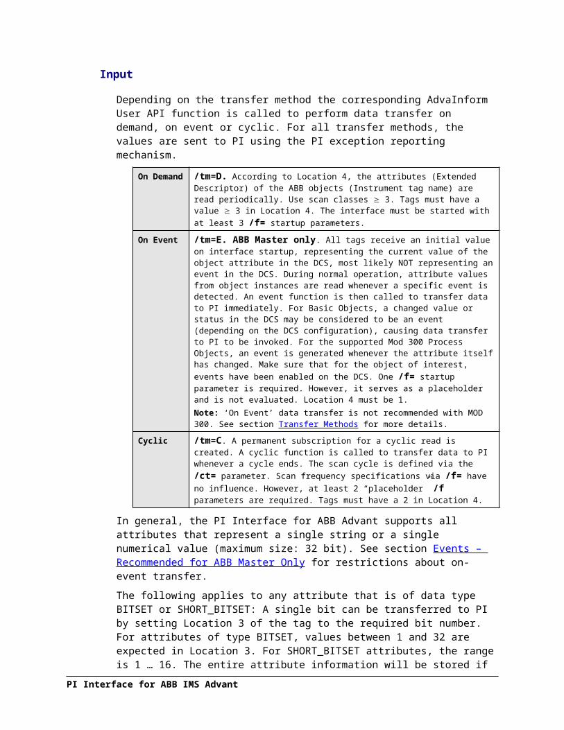
Input
Depending on the transfer method the corresponding AdvaInform User API function is called to perform data transfer on demand, on event or cyclic. For all transfer methods, the values are sent to PI using the PI exception reporting mechanism.
On Demand
/tm=D. According to Location 4, the attributes (Extended Descriptor) of the ABB objects (Instrument tag name) are read periodically. Use scan classes 3. Tags must have a value 3 in Location 4. The interface must be started with at least 3 /f= startup parameters.
PI Interface for ABB IMS Advant

On Event /tm=E. ABB Master only. All tags receive an initial value on interface startup, representing the current value of the object attribute in the DCS, most likely NOT representing an event in the DCS. During normal operation, attribute values from object instances are read whenever a specific event is detected. An event function is then called to transfer data to PI immediately. For Basic Objects, a changed value or status in the DCS may be considered to be an event (depending on the DCS configuration), causing data transfer to PI to be invoked. For the supported Mod 300 Process Objects, an event is generated whenever the attribute itself has changed. Make sure that for the object of interest, events have been enabled on the DCS. One /f= startup parameter is required. However, it serves as a placeholder and is not evaluated. Location 4 must be 1.Note: ‘On Event’ data transfer is not recommended with MOD 300. See section Transfer Methods for more details.
Cyclic /tm=C. A permanent subscription for a cyclic read is created. A cyclic function is called to transfer data to PI whenever a cycle ends. The scan cycle is defined via the /ct= parameter. Scan frequency specifications via /f= have no influence. However, at least 2 “placeholder” /f parameters are required. Tags must have a 2 in Location 4.
In general, the PI Interface for ABB Advant supports all attributes that represent a single string or a single numerical value (maximum size: 32 bit). See section Events – Recommended for ABB Master Only for restrictions about on-event transfer.
The following applies to any attribute that is of data type BITSET or SHORT_BITSET: A single bit can be transferred to PI by setting Location 3 of the tag to the required bit number. For attributes of type BITSET, values between 1 and 32 are expected in Location 3. For SHORT_BITSET attributes, the range is 1 … 16. The entire attribute information will be stored if location 3 contains zero. Information about the data type of an attribute can be obtained from AdvaInform Object Types Reference Manual or via getObj.
For detailed information about meaning and spelling of the attributes, see the description sections for the ABB objects in the AdvaInform Object Types Reference Manual. You can also list object attributes via ABB’s getObj example program. Refer to section Attribute Lists via getObj.
Tags will receive DCS Failed in PI if the object status returned by the AdvaInform UserAPI functions is different from bciOBJ_SUCCESS.
In addition, if for an On-Demand interface, the bciDoRequest call fails, i.e. the returned AdvaInform UserAPI status is different from bciSUCCESS, all tags in the affected scan class will also receive this Digital State. In such a case, the overall UserAPI call already failed. Subsequent object-by-object checking does not make sense and is skipped.
Quality Check for Selected Attributes
For objects of type AI and AO the attribute VALUE is checked against the attribute STATUS (which is always read simultaneously) before it is stored in PI:STATUS Bit 1 (active) must be equal to 1STATUS Bit 2 (error) must be equal to 0
In all other cases the tag receives Set to Bad.
For Objects of type DI and DO there is a quality check if you read the attribute STATUS. Any bit of this 32-bit entity can be stored as 0 or 1 in the PI tag. The number of the required bit (range 1 … 32) must be stored in location 3 of the tag. If bit 9 (the value bit) is selected, it will be checked against bits 1 and 2, which have the same meaning as for AI and AO objects. Bit 9 will be stored in the PI tag, if the following conditions are fulfilled:
PI Interface for ABB IMS Advant

STATUS Bit 1 (active) must be equal to 1STATUS Bit 2 (error) must be equal to 0
In all other cases the tag receives Set to Bad.
The numerical value of the attribute MEASURE is stored in PI, if the quality-attribute DQ_MEAS for that object is equal to 1. Otherwise, the tag receives Set to Bad. A similar check is performed for the attribute RESULT. The quality attribute DATAQUAL is checked to make sure that RESULT is valid. If DATAQUAL contains a value other than 1, the tag will be Set to Bad.
Output
The AdvaInform User API provides functions for executing operations in object instances. This is the only way to update values. The updating process is invoked by the means of the PI event handling functions. At interface startup a list of output tags will be established. These tags must either contain a valid PI tag name in the SourceTag field or the field must be left blank in which case writes to the DCS are performed if the output tag itself changes value in PI.
PI will inform the interface whenever a source tag has received a new value. The output tag will then be updated with the value of the source tag. Finally, the value gets sent to the DCS. See section Introduction for detailed information about conventions regarding operations for the various ABB object types and resulting restrictions. Furthermore, information about operations can be found in the Object Types Reference Manual for ABB Master or MOD 300. Using getObj is also possible. See section Attribute Lists via getObj. Output tags must have a value > 2 in location 4, i.e. they must belong to an ‘On Demand’ interface.
Outputs to the DCS can be totally disabled by using the /nooutputs startup parameter.
The PI Interface for ABB Advant currently supports output to the DCS for selected object types and attributes. For writing towards the DCS, so-called operations are being used. Operations have names. For AI, AO, DI, DO, DAT and TEXT, the operation name is “ORDER”. Note that outputs to DAT objects could not yet be tested. Although PIDCON, PIDCONA, MULTIDAT, VALVECON, MOTCON, MANSTN and RATIOSTN objects have an operation “ORDER” as well, output to these object types is not yet supported.
For MOD 300 process objects of type CCF and TLL, the operation name is just the attribute name, with a preceding “PUT_”. For example, the name of the operation that is used to write a value back to the attribute “MEASURE” is “PUT_MEASURE”. If the interface finds the “PUT_” construction in the list of available operations, even for object types other than CCF and TLL, this attribute can be updated in the DCS. Otherwise, output is not supported.
Note that all event and operation name constructions discussed above are automatically performed by the interface internally. There is no impact on what the user has to specify in the Extended Descriptor (attribute name) and the Instrument tag name (object name).
Example:
You want to write to the attribute SETPOINT of FIC-100, which is an object of type CCF_PID_LOOP. Enter ATTRIB= SETPOINT into the tag’s Extended Descriptor. To make sure that writing will be possible, check the object via getObj.$ getObj FIC-100===============================================================Object FIC-100 is of type CCF_PID_LOOP which has:---------------------------------------------------------------…
PI Interface for ABB IMS Advant

Principles of Operation
247 SETPOINT FLOAT 4 byte…-Operations----------------------------------------------------…249 PUT_SETPOINT OPERATION 4 byte…
The interface finds SETPOINT in the Extended Descriptor. Then it retrieves a list of all operations supported for FIC-100. One of the operations is PUT_SETPOINT. This is what the interface expects, thus writing to this attribute will be possible.
Connection to the PI Server
Connection to the PI server is necessary for the PI Interface for ABB Advant to start. If it cannot connect, it will try again in an endless loop. If you are not aware of your PI Home Node being down, test the connection between the API Node (the IMS) and the PI Home Node. For instance, execute this example program $PIHOME/bin/apisnap. If connection to the PI Home Node is established, it will ask you for a tag name and display the snapshot. In case of failure, please check the network connection. It is also a good idea to verify that access to the PI Home node is permitted. In PI 2 systems, the name of the IMS must appear with Read/Write access in PISysDat:PIServer.dat. In PI 3 systems, verify, that the PI Proxy Table and the PI Firewall table are set up to allow point and data access by the IMS.
If the PI API detects connection problems to the PI Home Node, this will be reported in $PIHOME/dat/pimesslogfile. However, if buffering is switched on, you will not lose data. You can find detailed information about buffering in the PI API Manual. Missing connection to the PI server will not disturb the interface processes on the IMS.
Connection to the DCS
In case of connection problems with the DCS, the PI Interface for ABB Advant will receive error statuses from the AdvaInform UserAPI functions. Any object related return status that is different from bciOBJ_SUCCESS would result in DCS Failed for the corresponding tag in PI.
If a controller node is down, or if the cable between the IMS and the DCS gets unplugged, bciOBJ_NODE_DOWN will be returned. However, when the node is back up or the cable is plugged in again, the interface is not able to reconnect. This is a known problem in the AdvaInform UserAPI. Starting with version 3.20, the PI Interface for ABB Advant has a workaround built in. Whenever bciOBJ_NODE_DOWN is received, the interface deletes ALL requests (or cancels all cyclic/event subscriptions, respectively) towards the controllers. It will rebuild ALL lists and try to reconnect after a configurable amount of time (see parameter /try in section Startup Command File. The interface is not able to detect the node(s) being down. Thus, even if only part of the DCS environment is currently unreachable, all tags are affected. They will not receive new data until all objects that were addressed on interface startup are reachable again.
Important Note: If you decide to restart the interface in a situation where only one or a few, but not all DCS nodes are down, it will most likely start to work immediately. However, you will notice that fewer tags have been found than in previous instances. This happens because the objects that were in the state bciOBJ_NODE_DOWN before will now cause the corresponding tags to be rejected. The interface will start with a subset of tags, involving only the objects being currently reachable. Though restarting the interface is a possible workaround in cases where a partial DCS node

shutdown is planned and known of, it is important to restart the interface again after the node is back up. During the downtime of one node, you can ensure data collection for the other nodes via a temporary interface restart. But in order to come back to the full set of tags, another restart is necessary after the problem has disappeared.Note: You can disable the workaround and consider the above problem solved if the appropriate patch supplied by ABB was applied to your IMS/AEH. The patch is available for IMS 2.0. See the description of the /ndw startup parameter in section Startup Command File for more information. Starting with AEH 2.1 on HP-UX or 3.1 on Windows, the fix is implemented in the product and no longer appears as a patch.
Timestamps
For time stamping tag values, the PI Interface for ABB Advant can use local time of the Advant Station or PI Server time. The behavior is controlled by the setting of /timsrc. Local time of the Advant Station will be used if /timsrc=A is specified on the command line, or if the /timsrc parameter is missing. PI Server time will be used in case of /timsrc=P.
On Windows, it is possible to run the PI Interface for ABB Advant on an AEH that does not observe DST, i.e. with the ‘Automatically adjust clock for daylight saving changes’ box unchecked under the ‘Time Zone’ tab of the Date/Time Properties applet. Use /timsrc=P in this case. The interface will continue to assign correct PI Server time stamps during DST transitions of the PI Server despite of the AEH not performing the one hour forward or backward jump in local time. It is possible to adjust AEH time to correct local time (which results in incorrect UTC during ‘Summer time’). The interface will still send correct PI Server time stamps. However, the interface and bufserv must be stopped prior to changing local time on the NT AEH. They must be restarted afterwards.
Important Notes- On Windows, in order to have /timsrc=P work correctly under all circumstances, it is mandatory to also specify /pisdk=1 in the interface startup file, i.e. enable use of the PI SDK.- Running the PI Interface for ABB Advant on an IMS or AEH with manually adjusted local time (i.e. incorrect UTC) is not supported on HP-UX. - Using PI Server time (/timsrc=P) on HP-UX is not supported if the interface runs on an AEH that resides in a location being off from GMT by a non-integral number of hours such as GMT+9:30 (Australian Central Standard Time, Australian Central Daylight Time (South Australia), CST-9:30CDT).
Sign-up for Updates
The interface periodically checks for alterations of the point database and performs the necessary operations such as adding, editing and deleting of tags. In case of editing, the tag will receive a status of Configure. Note that in case of on-event or cyclic transfer these interface activities are always suspended for duration according to the value specified via /du=. See section Startup Command File for the description of this parameter for further information.
PI Interface for ABB IMS Advant

Principles of Operation
Supported Object Types
Basic Objects
Object Read Write
Analog Input – AI Single numerical or string attribute VALUE
Analog Output – AO Single numerical or string attribute VALUE
Digital Input – DI Single numerical or string attribute Bit 9 of STATUS
Digital Output – DO Single numerical or string attribute Bit 9 of STATUS
Dat Objects – DAT Single numerical or string attribute Not tested
Text Objects – TEXT Single numerical or string attribute INT_LONG, TEXT_REAL, TEXT not tested
MOD 300 Process Objects
Object Read Write
CCF Objects Single numerical or string attribute Numerical attributeString attribute not tested
TLL Objects Single numerical or string attribute Numerical attributeString attribute not tested
TCL Objects Single numerical or string attribute Not tested
Other Object Types (Selection)
Object Read Write
PIDCON Single numerical or string attribute Not supported
PIDCONA Single numerical or string attribute Not supported
VALVECON Single numerical or string attribute Not supported
MOTCON Single numerical or string attribute Not supported
MANSTN Single numerical or string attribute Not supported
RATIOSTN Single numerical or string attribute Not supported
MULTIDAT Single numerical or string attribute Not tested
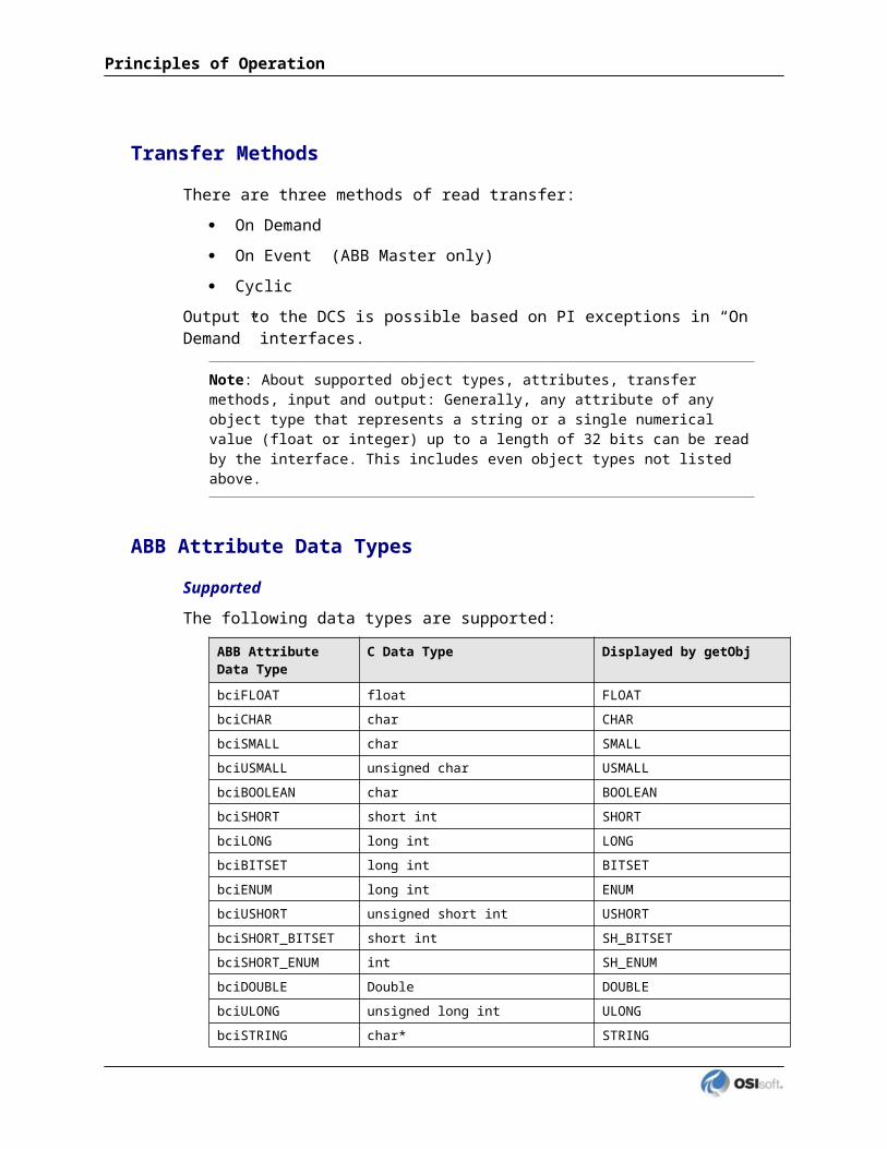
Transfer Methods
There are three methods of read transfer:
On Demand
On Event (ABB Master only)
Cyclic
Output to the DCS is possible based on PI exceptions in “On Demand” interfaces.
Note: About supported object types, attributes, transfer methods, input and output: Generally, any attribute of any object type that represents a string or a single numerical value (float or integer) up to a length of 32 bits can be read by the interface. This includes even object types not listed above.
ABB Attribute Data Types
SupportedThe following data types are supported:
ABB Attribute Data Type
C Data Type Displayed by getObj
bciFLOAT float FLOAT
bciCHAR char CHAR
bciSMALL char SMALL
bciUSMALL unsigned char USMALL
bciBOOLEAN char BOOLEAN
bciSHORT short int SHORT
bciLONG long int LONG
bciBITSET long int BITSET
bciENUM long int ENUM
bciUSHORT unsigned short int USHORT
bciSHORT_BITSET short int SH_BITSET
bciSHORT_ENUM int SH_ENUM
bciDOUBLE Double DOUBLE
bciULONG unsigned long int ULONG
bciSTRING char* STRING
Not SupportedThe following data types are NOT supported:
ABB Attribute Data Type
C Data Type Displayed by getObj
bciSTRUCT struct STRUCT
bciUNION union UNION
PI Interface for ABB IMS Advant

Principles of Operation
ABB Attribute Data Type
C Data Type Displayed by getObj
bciARRAY Array [] ARRAY
bciOPEN_ARRAY Array [] OPENARRAY
bciCOMPOSITION struct COMPOSITE
You can use ABB’s example program getObj to check if the attribute you want to read is supported. For more information about getObj, consult chapter “” later in this manual. There is no restriction other than the data type for an attribute to be supported.
Events – Recommended for ABB Master Only
There is an additional restriction if you want to read attributes “On Event” (ABB Master only). Events for ABB objects have names. For the Basic object types AI, AO, DI, DO and the other object types on ABB Master that were tested (PIDCON, PIDCONA, VALVECON, MOTCON, MANSTN, RATIOSTN), the name is always “EVENT”. For MOD 300 process objects of type CCF and TLL, the event name is just the attribute name, with a preceding “CHG_”. For example, the event name for the attribute “MEASURE” is “CHG_MEASURE”.
If the interface finds either “EVENT” or the “CHG_…” construction in the list of available events for the desired object type/attribute combination, the attribute can be read on event. If the event name follows other rules, then the attribute is currently unsupported for the event transfer method (you can read it “On Demand”, however). Note that DAT and TEXT objects are unable to generate events although the overview retrieved via getObj may state otherwise.
Important Note for MOD 300: Because the MOD 300 system is not an event-based system, events are simulated from the Advant nodes. Essentially, data to be retrieved on events is subscribed to by the core system. Subscriptions are set-up on a pre-determined subscription rate, which can result in missed events.In other words: Although the PI Interface for ABB Advant was written in a way that the use of the ‘On Event’ method is possible for both ABB Master and ABB Mod 300, this method is NOT recommended if your DCS is MOD 300. It works fine with ABB Master.The fact that the ‘On Event’ method is recommended for Master DCS only is documented in chapter 7 of the AdvaInform UserAPI User’s Guide, “FAQ and recommendations”.
UniInt FailoverThis interface supports UniInt failover Phase 2 Cold, Warm and Hot. Refer to the UniInt Failover Configuration chapter of this document for configuring the interface for failover.

Chapter 3. Installation Checklist
If you are familiar with running PI data collection interface programs, this checklist helps you get the interface running. If you are not familiar with PI interfaces, return to this section after reading the rest of the manual in detail.
This checklist summarizes the steps for installing this interface. You need not perform a given task if you have already done so as part of the installation of another interface. For example, you only have to configure one instance of Buffering for every interface node regardless of how many interfaces run on that node.
The Data Collection Steps below are required. Interface Diagnostics and Advanced Interface Features are optional.
Data Collection Steps
1. Verify that PI API has been installed. On a Windows system, the PI SDK is required.For a HP-UX system:
a Verify that the PI API has been installed.b. Need ‘root’ password if PI API has yet to be installed.c. Choose the cfront compatible PI API version 1.3.4 (higher HP-UX PI API
versions not supported at this time).d. Recommendation is to choose ‘ocsmgr’ as the PI API user.
2. Install the PI Interface for ABB Advant.For a HP-UX system: Link the Interface Control Program
3. Test the connection between the interface node and the foreign device using ABB’s example program getObj.
4. Define digital states.
5. Choose a point source.
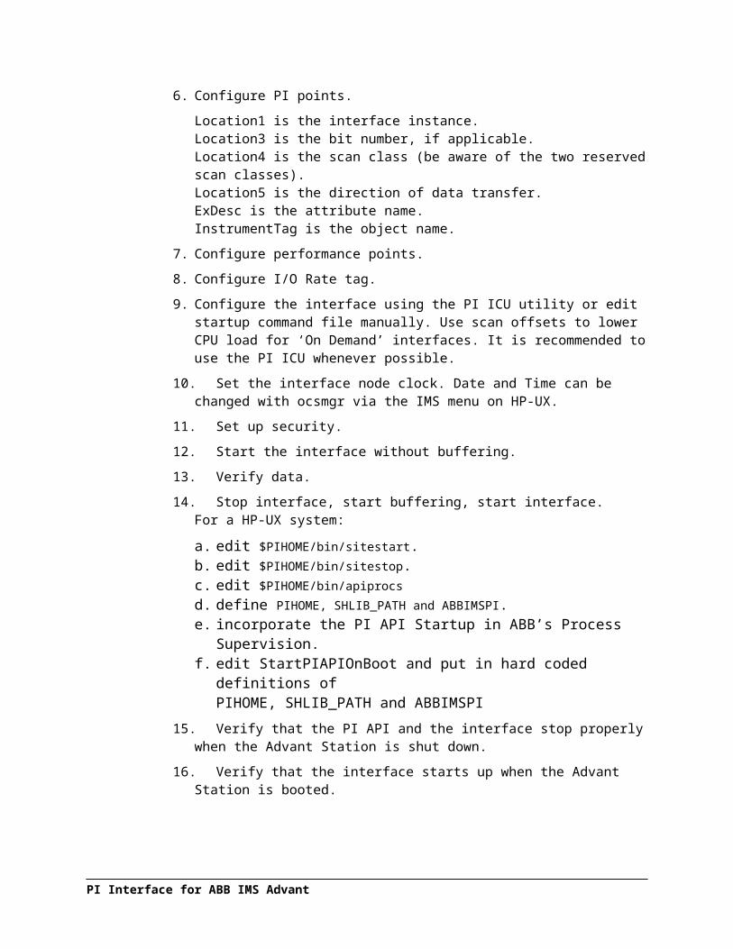
6. Configure PI points.
Location1 is the interface instance.Location3 is the bit number, if applicable.Location4 is the scan class (be aware of the two reserved scan classes).Location5 is the direction of data transfer.ExDesc is the attribute name.InstrumentTag is the object name.
7. Configure performance points.
8. Configure I/O Rate tag.
PI Interface for ABB IMS Advant

9. Configure the interface using the PI ICU utility or edit startup command file manually. Use scan offsets to lower CPU load for ‘On Demand’ interfaces. It is recommended to use the PI ICU whenever possible.
10. Set the interface node clock. Date and Time can be changed with ocsmgr via the IMS menu on HP-UX.
11. Set up security.
12. Start the interface without buffering.
13. Verify data.
14. Stop interface, start buffering, start interface.For a HP-UX system:
a. edit $PIHOME/bin/sitestart.b. edit $PIHOME/bin/sitestop.c. edit $PIHOME/bin/apiprocsd. define PIHOME, SHLIB_PATH and ABBIMSPI.e. incorporate the PI API Startup in ABB’s Process Supervision.f. edit StartPIAPIOnBoot and put in hard coded definitions of
PIHOME, SHLIB_PATH and ABBIMSPI15. Verify that the PI API and the interface stop properly when the Advant Station is shut
down.
16. Verify that the interface starts up when the Advant Station is booted.
Interface Diagnostics
1. Configure Scan Class Performance points.
2. Install the PI Performance Monitor Interface (Full Version only) on the interface node.
3. Configure Performance Counter points.
4. Configure UniInt Health Monitoring points
5. Configure the I/O Rate point.
6. Install and configure the Interface Status Utility on the PI Server Node.
7. Configure the Interface Status point.
Advanced Interface Features
1. Configure the interface for disconnected startup. Refer to the UniInt Interface User Manual for more details on UniInt disconnected startup.
2. Configure UniInt failover; see the UniInt Failover Configuration chapter in this document for details related to configuring the interface for failover.
PI Interface for ABB IMS Advant

Chapter 4. Interface Installation on Windows
OSIsoft recommends that interfaces be installed on interface nodes instead of directly on the PI Server node. An interface node is any node other than the PI Server node where the PI Application Programming Interface (PI API) is installed (see the PI API manual). With this approach, the PI Server need not compete with interfaces for the machine’s resources. The primary function of the PI Server is to archive data and to service clients that request data.
After the interface has been installed and tested, Buffering should be enabled on the interface node. Buffering refers to either PI API Buffer Server (Bufserv) or the PI Buffer Subsystem (PIBufss). For more information about Buffering see the Buffering chapter of this manual.
In most cases, interfaces on interface nodes should be installed as automatic services. Services keep running after the user logs off. Automatic services automatically restart when the computer is restarted, which is useful in the event of a power failure.
The guidelines are different if an interface is installed on the PI Server node. In this case, the typical procedure is to install the PI Server as an automatic service and install the interface as an automatic service that depends on the PI Update Manager and PI Network Manager services. This typical scenario assumes that Buffering is not enabled on the PI Server node. Bufserv can be enabled on the PI Server node so that interfaces on the PI Server node do not need to be started and stopped in conjunction with the PI Server, but it is not standard practice to enable buffering on the PI Server node. The PI Buffer Subsystem can also be installed on the PI Server. See the UniInt Interface User Manual for special procedural information.
Naming Conventions and Requirements
In the installation procedure below, it is assumed that the name of the interface executable is abbimspi.exe and that the startup command file is called abbimspi.bat.
When Configuring the Interface ManuallyIt is customary for the user to rename the executable and the startup command file when multiple copies of the interface are run. For example, abbimspi1.exe and abbimspi1.bat would typically be used for instance 1, abbimspi2.exe and abbimspi2.bat for instance 2, and so on. When an interface is run as a service, the executable and the command file must have the same root name because the service looks for its command-line parameters in a file that has the same root name.
PI Interface for ABB IMS Advant

Interface Directories
PIHOME Directory Tree
The [PIHOME] directory tree is defined by the PIHOME entry in the pipc.ini configuration file. This pipc.ini file is an ASCII text file, which is located in the %windir% directory.
For 32-bit operating systems, a typical pipc.ini file contains the following lines:[PIPC]PIHOME=C:\Program Files\PIPC
For 64-bit operating systems, a typical pipc.ini file contains the following lines:[PIPC]PIHOME=C:\Program Files (X86)\PIPC
The above lines define the root of the PIHOME directory on the C: drive. The PIHOME directory does not need to be on the C: drive. OSIsoft recommends using the paths shown above as the root PIHOME directory name.
Interface Installation Directory
The interface install kit will automatically install the interface to:PIHOME\Interfaces\ abbimspi\
PIHOME is defined in the pipc.ini file.
Interface Installation Procedure
The abbimspi interface setup program uses the services of the Microsoft Windows Installer. Windows Installer is a standard part of Windows 2000 and later operating systems. To install, run the appropriate installation kit.
abbimspi_#.#.#.#_.exe
Installing Interface as a Windows Service
The abbimspi interface service can be created, preferably, with the PI Interface Configuration Utility, or can be created manually.
PI Interface for ABB IMS Advant

Installing Interface Service with PI Interface Configuration Utility
The PI Interface Configuration Utility provides a user interface for creating, editing, and deleting the interface service:
Service Configuration
Service nameThe Service name box shows the name of the current interface service. This service name is obtained from the interface executable.
IDThis is the service ID used to distinguish multiple instances of the same interface using the same executable.
Display nameThe Display name text box shows the current Display Name of the interface service. If there is currently no service for the selected interface, the default Display Name is the service name with a “PI-” prefix. Users may specify a different Display Name. OSIsoft suggests that the prefix “PI-” be appended to the beginning of the interface name to indicate that the service is part of the OSIsoft suite of products.
PI Interface for ABB IMS Advant

Interface Installation on UNIX
Log on asThe Log on as text box shows the current “Log on as” Windows User Account of the interface service. If the service is configured to use the Local System account, the Log on as text box will show “LocalSystem.” Users may specify a different Windows User account for the service to use.
PasswordIf a Windows User account is entered in the Log on as text box, then a password must be provided in the Password text box, unless the account requires no password.
Confirm passwordIf a password is entered in the Password text box, then it must be confirmed in the Confirm password text box.
DependenciesThe Installed services list is a list of the services currently installed on this machine. Services upon which this interface is dependent should be moved into the Dependencies list using the
button. For example, if API Buffering is running, then “bufserv” should be selected from the list at the right and added to the list on the left. To remove a service from the list of
dependencies, use the button, and the service name will be removed from the Dependencies list.
When the interface is started (as a service), the services listed in the dependency list will be verified as running (or an attempt will be made to start them). If the dependent service(s) cannot be started for any reason, then the interface service will not run.
Note: Please see the PI Log and Windows Event Logger for messages that may indicate the cause for any service not running as expected.
- Add ButtonTo add a dependency from the list of Installed services, select the dependency name, and click the Add button.
- Remove ButtonTo remove a selected dependency, select the service name in the Dependencies list, and click the Remove button.
The full name of the service selected in the Installed services list is displayed below the Installed services list box.
Startup TypeThe Startup Type indicates whether the interface service will start automatically or needs to be started manually on reboot.
If the Auto option is selected, the service will be installed to start automatically when the machine reboots.
If the Manual option is selected, the interface service will not start on reboot, but will require someone to manually start the service.
If the Disabled option is selected, the service will not start at all.
Generally, interface services are set to start automatically.
CreateThe Create button adds the displayed service with the specified Dependencies and with the specified Startup Type.
Remove The Remove button removes the displayed service. If the service is not currently installed, or if the service is currently running, this button will be grayed out.
Start or Stop Service
The toolbar contains a Start button and a Stop button . If this interface service is not currently installed, these buttons will remain grayed out until the service is added. If this interface service is running, the Stop button is available. If this service is not running, the Start button is available.
The status of the interface service is indicated in the lower portion of the PI ICU dialog.
Installing Interface Service Manually
Help for installing the interface as a service is available at any time with the command:abbimspi.exe /help
Open a Windows command prompt window and change to the directory where the abbimspi1.exe executable is located. Then, consult the following table to determine the appropriate service installation command.
Note: In the following Windows Service Installtation Commands you may use either a slash (/) or dash (-) as the delimiter.
PI Interface for ABB IMS Advant
Status of the ICU
Service installed or uninstalled
Status of the Interface Service

Interface Installation on UNIX
Windows Service Installation Commands on an Interface Node or a PI Server Node with Bufserv implemented
Manual service abbimspi.exe /install /depend "tcpip bufserv"
Automatic service abbimspi.exe /install /auto /depend "tcpip bufserv"
*Automatic service with service ID
abbimspi.exe /serviceid X /install /auto /depend "tcpip bufserv"
Windows Service Installation Commands on an Interface Node or a PI Server Node without Bufserv implemented
Manual service abbimspi.exe /install /depend tcpip
Automatic service abbimspi.exe /install /auto /depend tcpip
*Automatic service with service ID
abbimspi.exe /serviceid X /install /auto /depend tcpip
*When specifying service ID, the user must include an ID number. It is suggested that this number correspond to the interface ID (/id) parameter found in the interface .bat file.
Check the Microsoft Windows Services control panel to verify that the service was added successfully. The services control panel can be used at any time to change the interface from an automatic service to a manual service or vice versa.

Chapter 5. Interface Installation on UNIX
One of the first issues that must be resolved is where the interface should be installed. Should the interface be installed on the PI Server node or on a remote interface node? OSIsoft recommends that the interface be installed on a remote interface node. The primary function of the server node is to archive data and to service the clients that request that data. The PI Server should not need to compete with interfaces for the machine’s resources. If the interface is installed on a remote interface node, then the PI API must be installed on that node before the interface is installed. Refer to the PI API manual.
When the interface is installed on a interface node, it is also a good idea to install and run Bufserv on the interface node. Bufserv is a utility program that provides the capability to store and forward events to a PI Server, allowing continuous data collection when the server is down for maintenance, upgrades, backups, and unexpected failures. It is not critical to install Bufserv before the initial installation of the interface. In fact, it is recommended that Bufserv be installed after the interface has been shown to work to ease troubleshooting. Refer to the PI API manual for installation instructions and additional information on Bufserv.
Currently there is no PI Buffer Subsystem for the UNIX platform. PI API Buffer Server is the only type of buffering available for the UNIX platform.
If the interface is installed on the PI Server node, the advantage of using Bufserv is diminished because it is no longer needed to protect against network failures. Bufserv would still allow data to be collected when the PI Server is brought down for routine maintenance, but this advantage must be weighed against the additional load that Bufserv incurs on the server. Typically, users do not choose to run Bufserv on the PI Server node. If Bufserv is used on the server node, make sure that Bufserv is started before any interfaces by the startup script for PI.
If the interface is installed on a server node, the interface should be configured to start and stop in conjunction with the PI Server. If the interface is installed on a interface node, then the interface should be configured to start and stop with the PI API. Site-specific scripts can be edited for this purpose, as described in the installation procedure below. The PI Server and the PI API, in turn, can be configured to start and stop automatically when the system is shut down or rebooted. Procedures for automatic startup and shutdown of PI or the PI API are platform specific. The automation procedures are discussed in the PI System Management chapter of the PI Server manuals.
PI Interface for ABB IMS Advant

Naming Conventions and Requirements
In the installation procedure below, it is assumed that the name of the interface executable is abbimspi.exe and that the startup command file is called abbimspi.sh.
Note: UNIX does not enforce file-naming conventions, and it is possible that the file name extensions for the actual interface executable and command files are different from .exe and .sh, or it is possible that the file extensions are eliminated entirely.
To run multiple copies of the interface from the same directory, it is necessary to rename the executable and the command file. It is customary to use abbimspi1.exe and abbimspi1.sh for interface number 1, abbimspi2.exe and abbimspi2.sh for interface number 2, and so on.
Interface Directories
PIHOME Directory
PIHOME is an environment variable that points to the base directory where the PI API is installed. The setting of environment variables is discussed in the PI API manual.
Interface Installation Directory
There are two conventions for the installation directory. The first convention is to place all copies of the interface into a single directory. If this convention is followed, it is recommended to place abbimspi1, abbimspi2, abbimspi3, etc., in the directory:[PIHOME]/Interfaces/abbimspi
The second convention is to create a separate interface directory for each copy of the interface. If this convention is followed, it is recommended to place abbimspi1, abbimspi2, abbimspi3, etc., in the directories:[PIHOME]/Interfaces/abbimspi1
[PIHOME]/Interfaces/abbimspi2
[PIHOME]/Interfaces/abbimspi3
and so on.
Create the installation directories as necessary.
PI Interface for ABB IMS Advant
Definition of Environment Variables
The interface ‘make’ procedure requires the following UNIX environment variables to be properly defined:
PIHOME: this is the PI API home directory, for example, /opt/piapiABBIMSPI:this is the interface subdirectory path beneath PIHOME
Example:
If your PI API HP-UX is installed under /opt/piapi, the PIHOME variable must point to /opt/piapi.$ echo $PIHOME/opt/piapi$
If the PI Interface for ABB Advant resides under /opt/piapi/abbimspi, the ABBIMSPI variable must point to abbimspi$ echo $ABBIMSPIabbimspi$
If the environment variable PIHOME does not exist, define it with the following commands:PIHOME=/opt/piapiexport PIHOME
If the environment variable ABBIMSPI does not exist, define it with the following commands:ABBIMSPI=abbimspiexport ABBIMSPI
In order to have PIHOME and ABBIMSPI available every time you log on, you may wish to put their definitions into /home/ocsmgr/.profile for user ocsmgr. Consult your HP-UX system administrator for more information.
The directory for the interface files is:$PIHOME/$ABBIMSPI/bin
The directory for the interface log files is:$PIHOME/$ABBIMSPI/log
PI Interface for ABB IMS Advant

Interface Installation on UNIX
Interface Installation Procedure
Before installing the PI ABB IMS/AEH Advant Interface itself, you must install the PI API HP-UX. Note that currently PI API version 1.3.4 is highest supported version. If you are installing the PI API from a distribution kit that is at a higher version (e.g. 1.3.8), you must choose to install the option “PI API v1.3.4 compatible with the HP-UX cfront compiler” when prompted. PI API 1.3.9.1 does not support the HP-UX cfront compiler and thus cannot be used for this interface.
For more information, see the Appendices, “UNIX Installation Procedures”, “UNIX Post Installation” and “HP-UX” in the PI API Application Programming Interface User Guide.
It is recommended to have ocsmgr own all PI API directories and the resulting processes, i.e. the requested “existing user name” should be ocsmgr. Note that the PI Interface for ABB Advant was compiled with cfront, so choose this option when asked (i.e. enter N to the question ‘Do you want to install the ANSI C++ [Y] or the cfront version?’).
The following sample installation log (taken from a PI API 1.3.4 installation) shows the required steps. User inputs during the installation are shown in bold red.Creating/Updating the PI API file systemPIHOME is properly defined: /opt/piapiSetting PI Environment VariablesInstalling PI API from /opt/piapi/buildBLDDIR existsLIBDIR existsBINDIR existsDATDIR existsINCDIR existsSRCDIR existsEnter an existing user name for PI API [piadmin] ?User name: ocsmgrFile: piclient.ini existsFile: iorates.dat existsDo you want to install the ANSI C++ [Y] or the cfront version? NVersion (10 20) API install type = 0Installing Base System – PI APIAPI Installation ScriptSetting Working DirectoryInstalling /opt/piapi/bin/pistart /opt/piapi/bin/pistopInstalling /opt/piapi/bin/apiverifyInstalling piapi.h piparams.h pidefs.h pistatus.h piba.h pisql.h piapix.h pidgstat.hInstalling /opt/piapi/lib/libpiapi.slInstalling /opt/piapi/lib/libpiapi.aInstalling files in /opt/piapi/bin: apisnap bufserv bufutil iorates ioshmcls ioshmsrv isbuf mqcls mqmgr mqsrv pilogsrv shootqRunning the Site Specific Link ScriptInstalling examples: apisnap.c apisnap.mak

If installing a higher PI API Version (e.g. 1.3.6, where the following sample was taken from), you will see this:This distribution contains1. PI API v1.3.4 compatible with the HP-UX cfront compiler2. PI API v1.3.4 compatible with the ANSI C++ compiler3. PI API v1.3.6 compatible with the ANSI C++ compiler and ANSI streamsIf your PI API programs (for example, PI Interfaces) do notmention ANSI C++ compiler compatibility or PI API v1.3.6 compatibility,choose option 1. You can always re-run this script to re-installanother version of the PI API. Which of the above PI API version do you wish to install: [1], 2, or 3?1
Choose “1”.
Starting with PI API version 1.3x, there is a utility $PIHOME/bin/apiverify. This script lists all PI API processes and allows you to detect whether one or more is/are missing. You can include the abbimspi process by simply editing the file $PIHOME/bin/apiprocs. After modification, it may look like this:bufservmqmgrmqsrvioshmsrvioratesabbimspi
A periodic execution of apiverify as part of the daily maintenance procedure will alert you if the interface process is missing.$ apiverifyNAME PID TIME %CPU VSZbufserv 22945 00:00:00 0 156mqmgr 22938 00:00:00 0 48mqsrv 22933 00:00:00 0 48ioshmsrv 22951 00:00:00 0 40iorates 22956 00:00:00 0 76WARNING: abbimspi is NOT running
Note: Multiple copies of the PI Interface for ABB Advant may be running while multiple instances of the native PI API processes must not. Unfortunately, the apiverify script is unable to distinguish between these cases and will issue a warning if multiple occurrences of the same process name are found. Ignore an interface related warning unless there are more interface copies showing up than you actually intended to start. See the following example.
$ apiverifyNAME PID TIME %CPU VSZbufserv 22945 00:00:00 0 156mqmgr 22938 00:00:00 0 48mqsrv 22933 00:00:01 0 48ioshmsrv 22951 00:00:00 0 40iorates 22956 00:00:00 0 76abbimspi 22990 00:00:00 0 300abbimspi 22993 00:00:00 0 256WARNING: multiple instances of abbimspi are running
PI Interface for ABB IMS Advant

Interface Installation on UNIX
In this case, if you have configured two interfaces, everything is okay. If you set up only one interface, you might have accidentally started it twice, maybe after an unsuccessful attempt to stop and a subsequent restart.
Interface Upgrade
Before you install the upgrade, make sure that you have a valid backup of your existing interface files. In particular, take care of your interface startup scripts. If you are using the names of the startup example files shipped with the kit, your files will get overwritten. Make sure that the HP-UX environment variables PIHOME and ABBIMSPI are defined. Insert the tape and copy the files.
Example:cd $PIHOME/$ABBIMSPI/bintar –xv
Installing/Upgrading from CD-ROM or a Downloaded File
Often, interfaces are shipped on CD-ROM. Furthermore; files can easily be exchanged by e-mail or supplied and downloaded via the OSI Download Center. You may get authorized to download an interface update from the OSI Download Center or receive a bug fix by e-mail. The file you receive via the download center, e-mail or on the CD-ROM is usually a self-extracting executable for Windows, containing a compressed tar file for HP-UX, the current interface manual and the Release Notes. For example, you may receive version 5.09 of the PI Interface for ABB Advant in the file abbims_5.09.exe. Detach this file to your PC and double-click it in the Windows Explorer.
In this example, after extraction, you will have the following files in c:\temp\abbimspiabbims_5.09.tar.Zabbimspi.docabbims_5.09.txt

You may want to keep abbimspi.doc and abbims_5.09.txt on your PC (although abbims_5.09.txt is copied to your UNIX system as well). If this is a new installation, create the interface directory:mkdir $PIHOME/$ABBIMSPIcd $PIHOME/$ABBIMSPImkdir binmkdir logcd bin
Next use ftp binary file transfer to move abbims_5.09.tar.Z to $PIHOME/$ABBIMSPI/bin on the Advant Station. Make a backup of the files in this directory prior to proceeding. Check that the file you just copied has kept the uppercase ‘Z’ at the end: abbims_5.09.tar.Z. (Otherwise, uncompress will not work.) Uncompress and un-tar the file:
$ uncompress abbims_5.09.tar.Z (this will leave abbims_5.09.tar)$ tar –xvf abbims_5.09.tar
Note: You can mount an NT CD ROM directly on the Advant Station and copy files. See in appendix H.
Interface Files for HP-UX StartPIAPIOnBoot PI API Start script for use with Process
Supervisionabbimscp.mak control program makefileabbimscp.o control program object fileabbimspi.o interface object fileuniint.o OSI universal interface object fileapiMake interface make scriptapiMakefile interface makefileifinfo interface informationifstop interface stop procedurePI_abbims_x.x.x.x.txt release notesabbimspi_event.sh.new interface startup example (event-based version)abbimspi_cyclic.sh.new -”- (cyclic version)abbimspi_demand.sh.new -”- (on demand version)
Additional Files after Linkabbimspi Interface executableabbimscp Control program executable
Linking the PI Interface for ABB Advant
The PI Interface for ABB Advant must be re-linked any time you receive a new interface version. Furthermore, the interface should be linked whenever the PI API-HP-UX is linked. Linking of the PI API is done by executing $PIHOME/build/pi.install.$ cd $PIHOME/$ABBIMSPI/bin$ apiMake abbimspi
Make sure the PI API is running when you perform the link procedure.
PI Interface for ABB IMS Advant
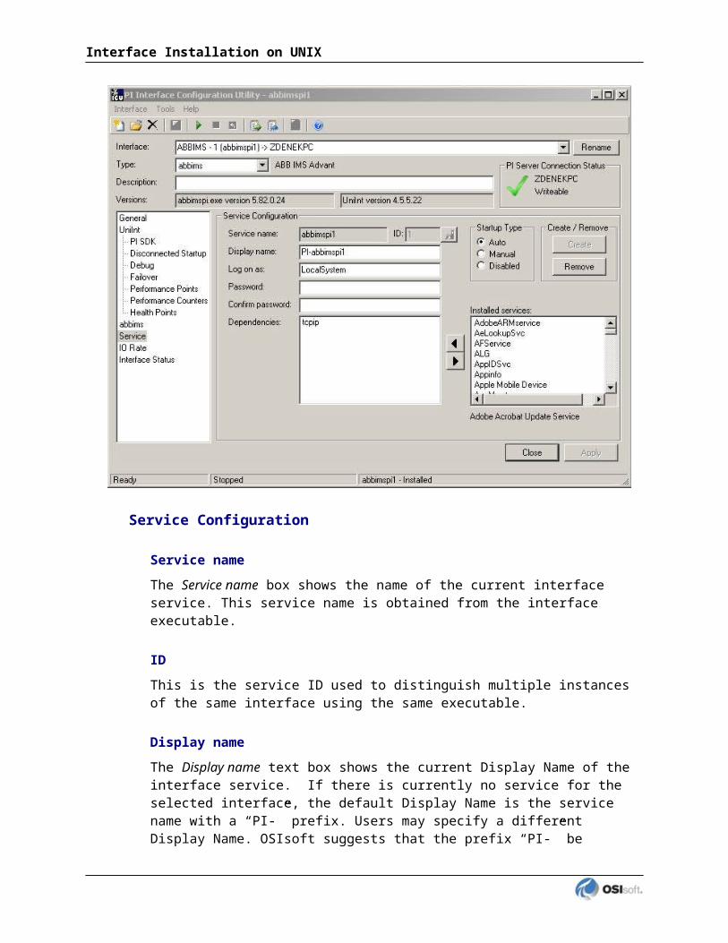
Interface Installation on UNIX
Linking the Interface Control Program$ cd $PIHOME/$ABBIMSPI/bin$ make –f abbimscp.mak
HP-UX Ownership of Interface Files
A user with sufficient privileges to execute ABB functions should own the interface files. This is typically ocsmgr.
The recommended method is to have the complete PI API tree owned by the account ocsmgr:
$ chown –R ocsmgr $PIHOME$ chgrp –R ocs $PIHOME
Under control of ocsmgr, the PI API has proven to function correctly and you will not have any problems when executing ABB functions. The drawback is: If you want to make the PIHOME and ABBIMSPI environment variables (discussed in section Definition of Environment Variables) permanent by defining them in files being executed on login or system boot, you must be permitted to modify .profile of ocsmgr or even root. Also note that these files will be overwritten on IMS/AEH/HP-UX upgrades.
If you want to use ABB’s Process Supervision for automatic startup of the PI Interface for ABB Advant on IMS startup, make sure that ocsmgr has enough privileges to access PI API and PI Interface for ABB Advant files. A process started up automatically by the Process Supervision functionality is started and owned by the ocsmgr user. If your PI API tree is owned by ocsmgr, you will not have any problem.
See your HP-UX system administrator to allow or help you perform necessary configuration tasks.

Chapter 6. Digital States
For more information regarding Digital States, refer to the PI Server documentation.
Digital State SetsPI digital states are discrete values represented by strings. These strings are organized in PI as digital state sets. Each digital state set is a user-defined list of strings, enumerated from 0 to n to represent different values of discrete data. For more information about PI digital tags and editing digital state sets, see the PI Server manuals.
An interface point that contains discrete data can be stored in PI as a digital point. A digital point associates discrete data with a digital state set, as specified by the user.
System Digital State SetSimilar to digital state sets is the system digital state set. This set is used for all points, regardless of type, to indicate the state of a point at a particular time. For example, if the interface receives bad data from the data source, it writes the system digital state Bad Input to PI instead of a value. The system digital state set has many unused states that can be used by the interface and other PI clients. Digital States 193-320 are reserved for OSIsoft applications.
PI Interface for ABB IMS Advant

Chapter 7. PointSource
The PointSource is a unique, single or multi-character string that is used to identify the PI point as a point that belongs to a particular interface. For example, the string Boiler1 may be used to identify points that belong to the MyInt interface. To implement this, the PointSource attribute would be set to Boiler1 for every PI point that is configured for the MyInt interface. Then, if /ps=Boiler1 is used on the startup command-line of the MyInt interface, the interface will search the PI Point Database upon startup for every PI point that is configured with a PointSource of Boiler1. Before an interface loads a point, the interface usually performs further checks by examining additional PI point attributes to determine whether a particular point is valid for the interface. For additional information, see the /ps parameter. If the PI API version being used is prior to 1.6.x or the PI Server version is prior to 3.4.370.x, the PointSource is limited to a single character unless the SDK is being used.
Case-sensitivity for PointSource AttributeThe PointSource character that is supplied with the /ps command-line parameter is not case sensitive. That is, /ps=P and /ps=p are equivalent.
Reserved Point SourcesSeveral subsystems and applications that ship with PI are associated with default PointSource characters. The Totalizer Subsystem uses the PointSource character T, the Alarm Subsystem uses @ for Alarm Tags, G for Group Alarms and Q for SQC Alarm Tags, Random uses R, RampSoak uses 9, and the Performance Equations Subsystem uses C. Do not use these PointSource characters or change the default point source characters for these applications. Also, if a PointSource character is not explicitly defined when creating a PI point; the point is assigned a default PointSource character of Lab (PI 3). Therefore, it would be confusing to use Lab as the PointSource character for an interface.
Note: Do not use a point source character that is already associated with another interface program. However it is acceptable to use the same point source for multiple instances of an interface.
PI Interface for ABB IMS Advant
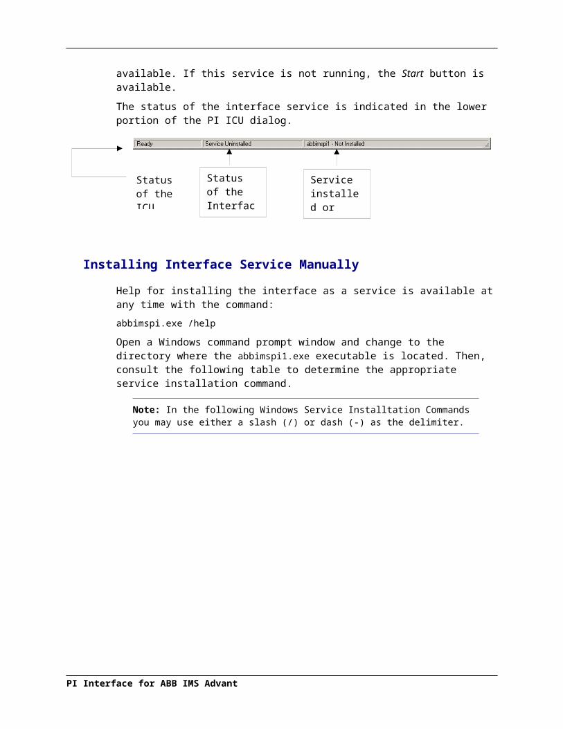
Chapter 8. PI Point Configuration
The PI point is the basic building block for controlling data flow to and from the PI Server. A single point is configured for each measurement value that needs to be archived.
Point Attributes
Use the point attributes below to define the PI point configuration for the interface, including specifically what data to transfer.
This document does not discuss the attributes that configure UniInt or PI Server processing for a PI point. Specifically, UniInt provides exception reporting and the PI Server provides data compression. Exception reporting and compression are very important aspects of data collection and archiving, which are not discussed in this document.
Note: See the UniInt Interface User Manual and PI Server documentation for information on other attributes that are significant to PI point data collection and archiving.
Tag
The Tag attribute (or tag name) is the name for a point. There is a one-to-one correspondence between the name of a point and the point itself. Because of this relationship, PI documentation uses the terms “tag” and “point” interchangeably.
Follow these rules for naming PI points:
The name must be unique on the PI Server.
The first character must be alphanumeric, the underscore (_), or the percent sign (%).
Control characters such as linefeeds or tabs are illegal.
The following characters also are illegal: * ’ ? ; { } [ ] | \ ` ' "
LengthDepending on the version of the PI API and the PI Server, this interface supports tags whose length is at most 255 or 1023 characters. The following table indicates the maximum length of this attribute for all the different combinations of PI API and PI Server versions.
PI API PI Server Maximum Length
1.6.0.2 or higher 3.4.370.x or higher 1023
1.6.0.2 or higher Below 3.4.370.x 255
Below 1.6.0.2 3.4.370.x or higher 255
Below 1.6.0.2 Below 3.4.370.x 255
PI Interface for ABB IMS Advant
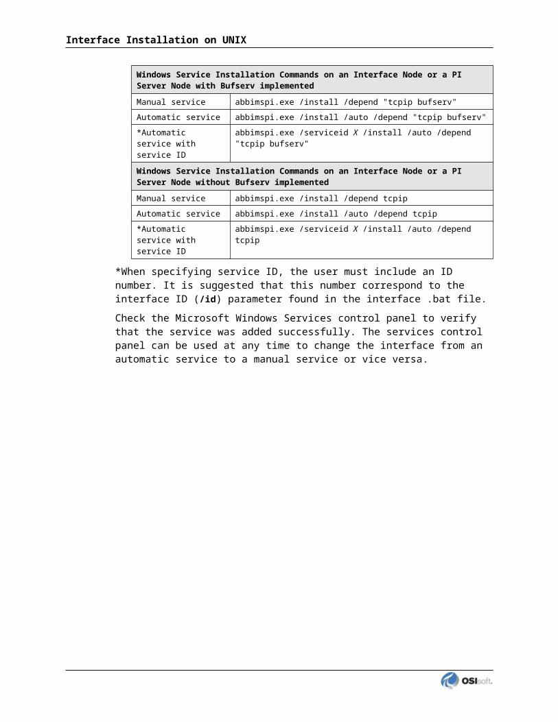
If the PI Server version is earlier than 3.4.370.x or the PI API version is earlier than 1.6.0.2, and you want to use a maximum tag length of 1023, you need to enable the PI SDK. See Appendix B for information.
PointSource
The PointSource attribute contains a unique, single or multi-character string that is used to identify the PI point as a point that belongs to a particular interface. For additional information, see the /ps command-line parameter and the PointSource chapter.
PointType
Typically, device point types do not need to correspond to PI point types. For example, integer values from a device can be sent to floating-point or digital PI tags. Similarly, a floating-point value from the device can be sent to integer or digital PI tags, although the values will be truncated.
Float16, float32, float64, int16, int32, digital, string, and blob point types are supported. For more information on the individual PointTypes, see PI Server manuals.
Location1
Location 1 contains the interface number. This number must match the one specified via the /in= startup parameter. Otherwise, the tag will be rejected silently, i.e. without creating a message in the log files. Multiple copies of the PI Interface for ABB Advant can run on the same Advant Station.
Location2
Location2 is not used by this interface.
Location3
If the attribute you want to read is of type BITSET (for example STATUS of a DI object) or SHORT_BITSET (for example STATUS of a TEXT object), Location 3 can be used to specify the number of the specific bit you want to store in PI. In this case, Location 3 must contain a number between 1 and 32 (for attributes of type BITSET) or between 1 and 16 (for attributes of type SHORT_BITSET), respectively. The entire attribute value (a 32 or 16 bit integer) can be read by setting Location 3 to 0.
A common example is the VALUE bit (also called VALUE Terminal) of the STATUS attribute of a DI or DO. The actual “value” of a DI or DO is just one bit of STATUS, namely bit 9. To read this “value”, the Extended Descriptor must contain ATTRIB=STATUS and Location 3 must be set to 9.
Location4
The scan class is stored here. The scan frequency of the tag is controlled by this location parameter. For example, a ‘3’ in Location 4 corresponds to the 3rd /f= startup parameter.
There are two reserved scan classes:PI Interface for ABB IMS Advant

Specify 1 for event-based reads (ABB Master only). The /tm parameter for event-based reads must be E.
Specify 2 for cyclic reads. The /tm parameter for cyclic-based reads must be C.
Specify 3 or greater for demand-based (scan class) reads and all outputs. The /tm parameter for these points must be D.
Output tags must reside in an on-demand scan class, which means that location 4 contains a value greater than 2. For those tags, the scan class is used to prevent the tag from being entered into an event or cyclic interface instance. The corresponding /f= parameter is not evaluated for output tags as outputs are always performed when the source tag changes.
Note: The number of points per scan class must NOT exceed 1500 or this can result in failure of the PI Interface for ABB Advant. If more than 1500 tags should be serviced at the same time, please use an additional scan class with the same scan-frequency for the next 1500 tags. See appendix Achieving Better Interface Performance.
Location5
This is the direction of data transfer. Choose 0 for input tags, i.e. if data are input from the DCS to PI. Choose 1 for output tags, i.e. if data are output from PI to the DCS. If set to 1, make sure the output tag belongs to an ‘On Demand’ interface.
InstrumentTag
Object name in ABB Master or ABB MOD 300.
LengthDepending on the version of the PI API and the PI Server, this interface supports an InstrumentTag attribute whose length is at most 32 or 1023 characters. The following table indicates the maximum length of this attribute for all the different combinations of PI API and PI Server versions.
PI API PI Server Maximum Length1.6.0.2 or higher 3.4.370.x or higher 1023
1.6.0.2 or higher Below 3.4.370.x 32
Below 1.6.0.2 3.4.370.x or higher 32
Below 1.6.0.2 Below 3.4.370.x 32
If the PI Server version is earlier than 3.4.370.x or the PI API version is earlier than 1.6.0.2, and you want to use a maximum InstrumentTag length of 1023, you need to enable the PI SDK. See Appendix B for information.
ExDesc
The Extended Descriptor is used to store the attribute to be read or modified.
PI Interface for ABB IMS Advant

PI Point Configuration
LengthDepending on the version of the PI API and the PI Server, this interface supports an ExDesc attribute whose length is at most 80 or 1023 characters. The following table indicates the maximum length of this attribute for all the different combinations of PI API and PI Server versions.
PI API PI Server Maximum Length
1.6.0.2 or higher 3.4.370.x or higher 1023
1.6.0.2 or higher Below 3.4.370.x 80
Below 1.6.0.2 3.4.370.x or higher 80
Below 1.6.0.2 Below 3.4.370.x 80
If the PI Server version is earlier than 3.4.370.x or the PI API version is earlier than 1.6.0.2, and you want to use a maximum ExDesc length of 1023, you need to enable the PI SDK. See Appendix B for information.
Syntax:ATTRIB=<attribute name>
Examples:ATTRIB=VALUEATTRIB=MEASUREATTRIB=DEV_STAT
The attribute name specified must exactly match one of the attribute names available for the required object type, including uppercase/lowercase spelling. The PI Interface for ABB Advant automatically retrieves the object type of a given object name. See also description of the InstrumentTag field.
To configure a tag, it is necessary to know which attributes are available in the DCS for a specific object type because the PI Interface for ABB Advant will compare the attribute specified in the Extended Descriptor against the list of valid attributes. Tags with an invalid attribute – object name combination (i.e. an invalid ExDesc – InstrumentTag combination) will be rejected by the PI Interface for ABB Advant.
For lists of supported attributes (and their exact names), refer to the AdvaInform Object Types Reference Manual. The interface supports only attributes that represent a single string or a single numerical value (maximum size 32 bit). It is possible to retrieve a summary of attributes, events and operations for a specific object type via getObj.
See appendix Attribute Lists via getObj for more information.
Performance Points For UniInt-based interfaces, the extended descriptor is checked for the string “PERFORMANCE_POINT”. If this character string is found, UniInt treats this point as a performance point. See the section called Scan Class Performance Points.
Scan
By default, the Scan attribute has a value of 1, which means that scanning is turned on for the point. Setting the scan attribute to 0 turns scanning off. If the scan attribute is 0 when the interface starts, a message is written to the pipc.log and the tag is not loaded by the interface. There is one exception to the previous statement.

If any PI point is removed from the interface while the interface is running (including setting the scan attribute to 0), SCAN OFF will be written to the PI point regardless of the value of the Scan attribute. Two examples of actions that would remove a PI point from an interface are to change the point source or set the scan attribute to 0. If an interface-specific attribute is changed that causes the tag to be rejected by the interface, SCAN OFF will be written to the PI point.
Shutdown
The Shutdown attribute is 1 (true) by default. The default behavior of the PI Shutdown subsystem is to write the SHUTDOWN digital state to all PI points when PI is started. The timestamp that is used for the SHUTDOWN events is retrieved from a file that is updated by the Snapshot Subsystem. The timestamp is usually updated every 15 minutes, which means that the timestamp for the SHUTDOWN events will be accurate to within 15 minutes in the event of a power failure. For additional information on shutdown events, refer to PI Server manuals.
Note: The SHUTDOWN events that are written by the PI Shutdown subsystem are independent of the SHUTDOWN events that are written by the interface when the /stopstat=Shutdown command-line parameter is specified.
SHUTDOWN events can be disabled from being written to PI when PI is restarted by setting the Shutdown attribute to 0 for each point. Alternatively, the default behavior of the PI Shutdown Subsystem can be changed to write SHUTDOWN events only for PI points that have their Shutdown attribute set to 0. To change the default behavior, edit the \PI\dat\Shutdown.dat file, as discussed in PI Server manuals.
Bufserv and PIBufssIt is undesirable to write shutdown events when buffering is being used. Bufserv and PIBufss are utility programs that provide the capability to store and forward events to a PI Server, allowing continuous data collection when the PI Server is down for maintenance, upgrades, backups, and unexpected failures. That is, when the PI Server is shutdown, Bufserv or PIBufss will continue to collect data for the interface, making it undesirable to write SHUTDOWN events to the PI points for this interface. Disabling Shutdown is recommended when sending data to a Highly Available PI Server Collective. Refer to the Bufserv or PIBufss manuals for additional information.
Output Points
Output points control the flow of data from the PI Server to any destination that is external to the PI Server, such as a PLC or a third-party database. For example, to write a value to a register in a PLC, use an output point. Each interface has its own rules for determining whether a given point is an input point or an output point. There is no de facto PI point attribute that distinguishes a point as an input point or an output point.
Outputs are triggered for UniInt-based interfaces. That is, outputs are not scheduled to occur on a periodic basis. There are two mechanisms for triggering an output.
As of UniInt 3.3.4, event conditions can be placed on triggered outputs. The conditions are specified using the same event condition keywords in the extended descriptor as described below. The only difference is that the trigger tag is specified with the SourceTag attribute
PI Interface for ABB IMS Advant

PI Point Configuration
instead of with the “event” or “trig” keywords. For output points, event conditions are specified in the extended descriptor as follows:event_condition
The keywords in the following table can be used to specify trigger conditions.
Event Condition
Description
Anychange Trigger on any change as long as the value of the current event is different than the value of the previous event. System digital states also trigger events. For example, an event will be triggered on a value change from 0 to “Bad Input,” and an event will be triggered on a value change from “Bad Input” to 0.
Increment Trigger on any increase in value. System digital states do not trigger events. For example, an event will be triggered on a value change from 0 to 1, but an event will not be triggered on a value change from “Pt Created” to 0. Likewise, an event will not be triggered on a value change from 0 to “Bad Input.”
Decrement Trigger on any decrease in value. System digital states do not trigger events. For example, an event will be triggered on a value change from 1 to 0, but an event will not be triggered on a value change from “Pt Created” to 0. Likewise, an event will not be triggered on a value change from 0 to “Bad Input.”
Nonzero Trigger on any non-zero value. Events are not triggered when a system digital state is written to the trigger tag. For example, an event is triggered on a value change from “Pt Created” to 1, but an event is not triggered on a value change from 1 to “Bad Input.”
Trigger Method 1 (Recommended)
For trigger method 1, a separate trigger point must be configured. The output point must have the same point source as the interface. The trigger point can be associated with any point source, including the point source of the interface. Also, the point type of the trigger point does not need to be the same as the point type of the output point.
The output point is associated with the trigger point by setting the SourceTag attribute of the output point equal to the tag name of the trigger point. An output is triggered when a new value is sent to the Snapshot of the trigger point. The new value does not need to be different than the previous value that was sent to the Snapshot to trigger an output, but the timestamp of the new value must be more recent than the previous value. If no error is indicated, then the value that was sent to the trigger point is also written to the output point. If the output is unsuccessful, then an appropriate digital state that is indicative of the failure is usually written to the output point. If an error is not indicated, the output still may not have succeeded because the interface may not be able to tell with certainty that an output has failed.
Trigger Method 2
For trigger method 2, a separate trigger point is not configured. To trigger an output, write a new value to the Snapshot of the output point itself. The new value does not need to be different than the previous value to trigger an output, but the timestamp of the new value must be more recent than the previous value.
Trigger method 2 may be easier to configure than trigger method 1, but trigger method 2 has a significant disadvantage. If the output is unsuccessful, there is no tag to receive a digital state that is indicative of the failure, which is very important for troubleshooting.

Hints for Point Configuration
HP-UX
ABB provide example programs in the following directory:/opt/advant/UserAPI/examples
You can check whether the object name you entered into the instrument tag field and the requested attribute (in the Extended Descriptor via ATTRIB=…) are spelled correctly, and see the current value of attributes, using the utility getObj.
This tool is very useful to check the availability of an object. It is independent of PI and a good means for troubleshooting. For instance, if you see an error message in the interface output file regarding difficulties with ABB object access, and the getObj program yields the same message, then there is likely a problem in the DCS or the IMS. Example:$ /opt/advant/UserAPI/examples/getObj 142IT082 VALUEgetObj: bciGetAttributes(142IT082) API ERROR –100
The getObj program takes two arguments: object name and attribute name. If both are correct, getObj will return the current value of the attribute. For example:$ getObj OAKY1000E.UCL RESULTOAKY1000E.UCL RESULT = 17.00
You can obtain a list of available attributes, along with a summary of events and operations, by omitting the second argument. In order to get this summary information, it is also possible to use an object type name instead of an object name, for example:$ getObj AI
See appendix Attribute Lists via getObj for examples of summaries.
There are other example-programs you can use to test on-demand, cyclic or event-based reads. Depending on the object type, use getAI, getAO, getDI or getDO for Basic Objects. If these programs do not exist, create them with ABB’s apiMake script. Note that in this case, the C Compiler must be available on your IMS Advant Station. For example:$ apiMake getObj c89 +e –D_POSIX_SOURCE -I. –I.. –I/opt/advant/UserAPI/include -I/opt/advant/c++_complib/include -I/opt/advant/TypeDir/include -I/opt/advant/OMF/include -I/opt/advant/UXBase/include -IcLinking getObj …Stripping getObj …done
The example below shows how to retrieve an event-based value from an ABB Master DCS. If the object name is correct, this command will subscribe for events and return value and status on event.$ getAI PU-2891A cycle 0
Other choices of value for cycle behave differently, and are documented by entering the getAI command without arguments. In general, launching these examples without arguments will display usage information. For example:$ /opt/advant/UserAPI/examples/getObjSYNTAX: getObj ObjectName [ALL|FULL] Or: getObj ObjectName [ALL|FULL] Or: getObj ObjectName AttributeName1AttributeName2…AttributeName9] WHERE: ALL gives OPERATION and EVENT expansion
PI Interface for ABB IMS Advant

PI Point Configuration
and STRUCT, UNION & COMPOSITION attribute expansion AND: FULL gives additional ARRAY & BITSET attribute expansion
If you are unsure where to find the getObj or other example programs, use the UNIX find command, for example:$ find / -name getObj –print
This command searches for a file named getObj, beginning from the root “/”, and print out the complete path if the file was found.
If the program getObj is unable to resolve any objects that are known to reside in the DCS then it is possible that the IMS software has not started up correctly.
Restarting the IMS software must be done only after an authorized person has given the approval to do so since stopping the IMS software may affect the DCS.
The commands to restart the IMS 2.0 software are as follows:$ cd /home/ocsmgr$ su (you must enter the root password here)# ./IMSstop –v# ./IMSstart –v# exit
Note: The above considerations regarding ABB example programs, in particular getObj apply in a general manner also to Windows. On Advant Enterprise Historian (AEH) 3.0 getobj.exe resides inc:\Program Files\ABB\Advant\SystemModules\AdvaInform UserAPI\1.3\Examples
Increasing Shared Memory Size on HP-UX
As stated earlier in this manual, depending on the available resources, there is a limit on the number of points that can be retrieved from a single IMS Advant Station. If you reach the limit, you might get an error messageOut of shared memory!!!
In this case, contact your local ABB specialist and ask for the file to be checked:/etc/opt/advant/OMF/config.cfg
Look for a section [SharedMemory]. If possible yet, doubling the current value for the keyword Size may help to increase the number of objects that can be serviced. For example, if the Size was originally set to 4096, the file may look like this after doubling the value: [SharedMemory]# Size is in KbytesSize = 8192
Have this change only done by an authorized ABB engineer. Afterwards, the system must be monitored carefully to make sure the change has no negative impact on other components.
Increasing Shared Memory Size on Windows Systems
On Windows, the ‘size’ of the available shared memory is stored in the registry. Edit the following entry to modify it. Make sure to have this change done by authorized ABB personnel. On Advant Enterprise Historian (AEH) 3.0 the key is

HKEY_LOCAL_MACHINE\SOFTWARE\ABB\Advant\SystemModules\OMF\1.4\Private\config\SharedMemory\size
On Advant Enterprise Historian (AEH) 3.1 the key isHKEY_LOCAL_MACHINE\SOFTWARE\ABB\SystemServices\OMF\config\SharedMemory\Size
Note that “1.4” in the key above may have been increased on your system, e.g. to 1.5. Increasing the size of the shared memory may solve problems with interfaces ‘hanging’ at ABB functions such as bciDoRequest, if the number of tags/objects serviced by one bciDoRequest was increased and the PI Interface for ABB Advant used to work with fewer tags.
You may have to set the interface to debug level 4 in order to exactly determine where the interface is hanging.
For more information, consult the Advant MES Advant Enterprise Historian for Windows NT Administrator’s Guide.
How to Retrieve a List of all Available Objects
ABB MasterYou can retrieve an object list with the Object Reference Maintenance tool. Use the results (stored in the file /tmp/Reference.tmp) to fill the Tag name and the Instrument Tag name. The following step-by-step procedure explains how to get the information. This example was generated on an IMS connected to ABB Master.
At the bottom of the IMS screen, there is an ABB icon. Click this icon.
Choose “Station” -> “Object Reference Maintenance”.Choose “List Object References” -> “List”
The following mask details should apply:
Reference Status “Resolved”Object Type “All” (or a specific type you want)Node Type “All”Network “Own”Node “All”
Click OK and the list will appear.
To save the list, click Save List.
A message appears:The current object reference list will be saved as ‘/tmp/Reference.tmp’. If the file already exists it will be overwritten.
Check whether you need the old file, perhaps rename it, and then click OK.
ABB MOD 300The following hints, based on notes that have been taken during an installation, can be used to pull information for analog and digital tags, digital state sets and digital states out of a MOD 300 system.
Log on to the OS/ES (not the IMS).
PI Interface for ABB IMS Advant

PI Point Configuration
Run SQLplus using the project configuration account and password.Set linesize 1000set pagesize 50000===spool pimod300_ana.txtSELECT OBJ_ID,LOOP_DESC,LOENGUNLIM,HIENGUNLIM,MEAS_UNITS,MEASFCMNAM FROM LOOP_DEF ORDER BY OBJ_ID;spool offspool pimod300_digdesc.txtSELECT * FROM DEV_DESC;spool off ===spool pimod300_dig.txtSELECT OBJ_ID, DESCRIPSET, DEVICETYPE, LOOP_DESC FROM DEV_LOOPspool off
The DEV_DESC table has a field called OBJ_ID that corresponds to the DESCRIPSET field in the DEV_LOOP table (use for digitalset name in PI). The state descriptors are in fields named STATEVAL01, STATEVAL02 … STATEVAL16.

Chapter 9. Startup Command File
Command-line parameters can begin with a / or with a -. For example, the /ps=M and -ps=M command-line parameters are equivalent.
Notes for Windows For Windows, command file names have a .bat extension. The Windows continuation character (^) allows for the use of multiple lines for the startup command. The maximum length of each line is 1024 characters (1 kilobyte). The number of parameters is unlimited, and the maximum length of each parameter is 1024 characters.
The PI Interface Configuration Utility (PI ICU) provides a tool for configuring the interface startup command file.
Configuring the Interface with PI ICU
Note: PI ICU requires PI 3.3 or greater.
The PI Interface Configuration Utility provides a graphical user interface for configuring PI interfaces. If the interface is configured by the PI ICU, the batch file of the interface (abbimspi.bat) will be maintained by the PI ICU and all configuration changes will be kept in that file and the module database. The procedure below describes the necessary steps for using PI ICU to configure the ABBIMSPI interface.
From the PI ICU menu, select Interface, then NewWindows Interface Instance from EXE..., and then Browse to the abbimspi.exe executable file. Then, enter values for Host PI System, Point Source, and Interface ID#. A window such as the following results:
PI Interface for ABB IMS Advant

Interface name as displayed in the ICU (optional) will have PI- pre-pended to this name and it will be the display name in the services menu.
Click Add.
The following message should appear:
Note that in this example the Host PI Server is MKELLYD630W7. To configure the interface to communicate with a remote PI Server, select Connections…from the PI ICU Interface menu and select the default server. If the remote node is not present in the list of servers, it can be added.
Once the interface is added to PI ICU, near the top of the main PI ICU screen, the interface Type should be abbims. If not, use the drop-down box to change the interface Type to be abbims.
Click on Apply to enable the PI ICU to manage this instance of the abbims interface.
The next step is to make selections in the interface-specific page (that is, “abbims”) that allows you to enter values for the startup parameters that are particular to the abbimspi interface.
PI Interface for ABB IMS Advant
Since the PI ABB IMS/AEH Advant interface is a UniInt-based interface, in some cases the user will need to make appropriate selections in the UniInt page. This page allows the user to access UniInt features through the PI ICU and to make changes to the behavior of the interface.
To set up the interface as a Windows Service, use the Service page. This page allows configuration of the interface to run as a service as well as to starting and stopping of the interface service. The interface can also be run interactively from the PI ICU. To do that, select Start Interactive on the Interface menu.
For more detailed information on how to use the above-mentioned and other PI ICU pages and selections, please refer to the PI Interface Configuration Utility user guide. The next section describes the selections that are available from the abbims page. Once selections have been made on the PI ICU GUI, press the Apply button in order for PI ICU to make these changes to the interface’s startup file.
ABBims Interface Page
Since the startup file of the PI ABB IMS/AEH Advant interface is maintained automatically by the PI ICU, use the abbims page to configure the startup parameters and do not make changes in the file manually. The following is the description of interface configuration parameters used in the PI ICU Control and corresponding manual parameters.
PI Interface for ABB IMS Advant
Startup Command File
Abbims
The abbims ICU Control for PI ICU has one section. A yellow text box indicates that an invalid value has been entered or that a required value has not been entered.
General Parameters
Interface numberLocation1 of a tag must match the interface number in order to be serviced.
It is possible to run multiple PI Interface for ABB Advant on the same node. Due to ABB restrictions, the number of cyclic and event tags per application is limited. Therefore several interface processes may be necessary to service all tags. Each interface instance must have its own number. With this number, you can tell which interface caused a specific message in pimesslogfile or pipc.log. (/IN=#, Default: None)
Re-Connection rateThe command-line parameter specifies the number of seconds to wait before trying to re-establish a lost connection to the DCS. (/TRY=#, Default=300)
Debug levelThis command-line parameter is used to set the optional debug level (0-7)(/DEB=#, Default:0)

Node down workaroundThis check box either enables or disables the Node Down Workaround. For a detailed description of the Node Down situation, please refer to section Connection to the DCS. There is a fix available from ABB for this problem. (/NDW=#, Default:1 or checked)
Suppress Digital State "Configure"Prevents sending digital state "Configure" to tag when it is being edited. (/SupCon=#, Default:0, or unchecked)
Transfer Method
CyclicThis command-line parameter causes the interface to read data cyclically. (/TM=C, Default:D or On Demand)
On DemandThis command-line parameter causes the interface to read and write data on demand. (/TM=D, Default:D or On Demand)
On EventThis command-line parameter causes the interface to read data on event. (/TM=E, Default:D or On Demand)
Source Of Time StampsSee section Timestamps for more details
Local time of the Advant Station (/TIMSRC=A)
PI Server time (/TIMSRC=P)
Timing Parameters
Cycle timeThe parameter is only applicable when used with the /TM=C command-line parameter. The cycle time is used by the AdvaInform UserAPI function for cyclic reads. There is only one cycle time for one cyclic interface process. (/CT=x, Default:9)
Note that there are restrictions on the cyclic subscription intervals (IMS 1.1 and 1.2 support 1s, 3s and 9s intervals only). Refer to the AdvaInform UserAPI documentation and Release Description for further information.
Cyclic tags time-out The parameter is only applicable when used with the /TM=C command-line parameter. This specifies the maximum period accepted for a cyclic tag to be without new data.(/TO=#, Default:300)
PI Interface for ABB IMS Advant

Startup Command File
Cyclic and on-event subscription duration This command-line parameter set the duration in seconds for cyclic and on-event subscriptions. For more information see section Command Line Parameters.(/DU=#, Default: 1800, Range: 0-4096)
Additional ParametersThis section is provided for any additional parameters that the current ICU Control does not support.
Notes for UNIX For UNIX, command file names typically have a .sh extension, but UNIX does not enforce file-naming conventions. The backslash (\) continuation character allows for use of multiple lines for the startup command. There is no limit to the command-line length and there is no limit to the number or length of the command-line parameters.
Note: The UniInt Interface User Manual includes details about other command-line parameters, which may be useful.

Command-line Parameters
Parameter Description
/CacheModeRequired when using disconnected startupDefault: Not Defined
Required for disconnected startup operation. If defined, the /CacheMode startup parameter indicates that the interface will be configured to utilize the disconnected startup feature.
/CachePath=pathOptionalDefault: Not Defined
Used to specify a directory in which to create the point caching files. The directory specified must already exist on the target machine. By default, the files are created in the same location as the interface executable.If the path contains any spaces, enclose the path in quotes.Examples:/CachePath=D:\PIPC\Interfaces\CacheFiles/CachePath=D:/PIPC/Interfaces/CacheFiles/CachePath=D:/PIPC/Interfaces/CacheFiles/
Examples with space in path name:/CachePath="D:\Program Files\PIPC\MyFiles"/CachePath="D:/Program Files/PIPC/MyFiles"/CachePath="D:/Program Files/PIPC/MyFiles/"
/CacheSynch=#OptionalDefault: 250 ms
NOTE: Care must be taken when modifying this parameter. This value must be less than the smallest scan class period defined with the /f parameter. If the value of the /CacheSynch parameter is greater than the scan class value, input scans will be missed while the point cache file is being synchronized.The optional /CacheSynch=# startup parameter specifies the time slice period in milliseconds (ms) allocated by UniInt for synchronizing the interface point cache file with the PI Server. By default, the interface will synchronize the point cache if running in the disconnected startup mode. UniInt allocates a maximum of # ms each pass through the control loop synchronizing the interface point cache until the file is completely synchronized.Synchronization of the point cache file can be disabled by setting the value /CacheSynch=0. The minimum synchronization period when cache synchronization is enabled is 50ms Whereas, the maximum synchronization period is 3000ms (3s). Period values of 1 to 49 will be changed by the interface to the minimum of 50ms and values greater than 3000 will be set to the maximum interval value of 3000ms.Default: 250 msRange: {0, 50 – 3000} time in millisecondsExample: /CacheSynch=50 (use a 50ms interval) /CacheSynch=3000 (use a 3s interval) /CacheSynch=0 (do not synchronize the cache)
/ct=#OptionalDefault: 9
Cycle Time. Only applicable with /tm=C. Cycle time to be used by the AdvaInform UserAPI function for cyclic read. There is only one cycle time for one cyclic interface process. Note that there are restrictions on the cyclic subscription intervals (IMS 1.1 and 1.2 support 1s, 3s and 9s intervals only). Refer to the AdvaInform UserAPI documentation and Release Description for further information.
PI Interface for ABB IMS Advant
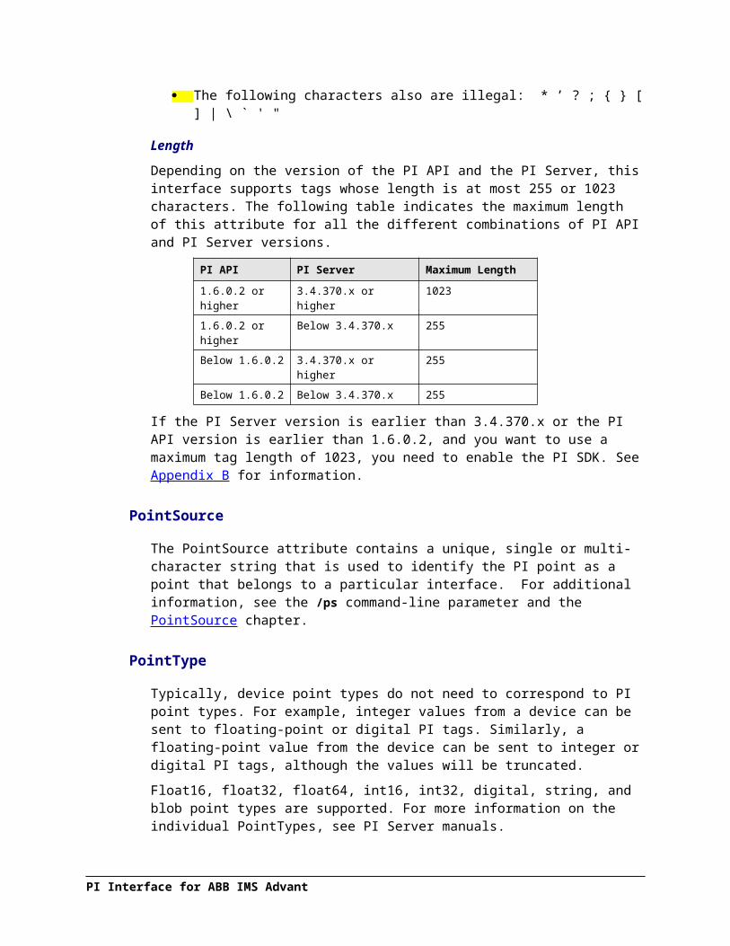
Startup Command File
Parameter Description
/dbuniint=0x0008OptionalRecommended
When the /dbuniint=0x0008 flag is present, the interface will send a message to the log file upon interface shutdown, reporting the signal number that caused it to terminate.The general format of the /dbuniint parameter is /dbuniint=level This parameter is used to set a debug level for debugging UniInt code. Level is a 32-bit integer. Setting a particular bit in level to 1 turns on a particular debug parameter. See the UniInt End User Document for more information. Use levels other than 0 and 0x0008 only upon recommendation of OSIsoft as it can result in very verbose log files. /dbuniint=0x0008 however does not cause repeated messages and can be permanently specified on the command line.
/deb=#OptionalDefault: 0
Debug level. This is the optional debug level (0-7). It defaults to a value of 0, which means that no additional output will be sent to the interface output file. Greater values result in more output information. On HP-UX, you can use the interface control program abbimscp to modify the debug level while the interface is running. In problem situations, debug level 4 (/deb=4) is recommended. However, this can result in a huge interface output file, depending on the number of tags. Make sure not to run the interface in debug level 4 for more than some minutes. Watch the available disk space when operating in debug mode to prevent the disk from filling up. In general, you should wait for instructions from OSIsoft about how long to run the interface in a high debug level if problems occurred, as different phases may need to be monitored (startup, data initialization, data collection, shutdown or even all of those). For example, in order to examine interface performance and to check DCS response times, a temporary change to Debug level 4 via the Control Program may be sufficient. After a while, the Debug level can be reset to 0. If start-up problems occur, you will probably have to edit the start-up script and restart the interface. You will have to revert your change after diagnosis is finished, to prevent the interface from always being started in high Debug mode. Eventually, to debug shut-down problems, increasing the Debug level on the fly via the Control Program + a subsequent interface stop may be required.

Parameter Description
/du=#OptionalDefault: 1800
Duration. Duration (in seconds) for cyclic and on-event subscriptions.Data collection using the cyclic or on-event method is initialized by a subscription of objects. The actual data transfer is done by the ABB function bciGetData. Periodically, after an amount of time according to /du= data collection is suspended. The interface returns from bciGetData, checks the PI Point Database and executes bciGetData again.
Behavior of the interface according to the specified value:
Small value, e.g. /du=60Short periods of continuous cyclic scanning or event watching, but frequent checking for changes in the PI point database; adding or deleting tags is immediately reflected by the interface;
Big value, e.g. /du=3600Long periods of continuous cyclic data collection or watching for events; changes in the PI point database can be recognized only after return from the ABB function, i.e. after e.g. 1 hour;Do not exceed the ABB limit for the duration (currently: 4096 seconds).Note for the ‘On Event’ interface: Between /du= periods, that is, when the interface checks for point updates, it is unable to receive events from the DCS. Although in practice, these intermediate periods usually do not last for more than a second, an event may happen exactly at this time and could get lost. To work around this problem, it is possible to specify a negative value for /du, for example /du=-1A negative value will cause the event-driven interface to stay in bciGetData forever. No event will ever be missed. The drawback is that the interface will not do anything else. You will not be able to add, edit or delete points for this interface while it is running. Instead, you must restart the event interface after a point edit. This is a significant difference to the standard OSI interface features but is caused by the fact that DCS events are not being buffered. If the final tag configuration is accomplished, start the event interface with /du=-1 and waive the capability of on-line point edits in favor of 100% data reception.Note for HP-UX: For the ‘duration’ seconds (if negative: forever), the interface will not reach any other place in the code except the callback functions that send event or cyclic data to PI. On HP-UX, these functions will check a mailbox for messages from the Control Program on a regular basis. Hence, a command issued by the Control Program will only be received on either the next cycle or on the next event, respectively.
PI Interface for ABB IMS Advant

Startup Command File
Parameter Description
/ec=#Optional
The first instance of the /ec parameter on the command-line is used to specify a counter number, #, for an I/O Rate point. If the # is not specified, then the default event counter is 1. Also, if the /ec parameter is not specified at all, there is still a default event counter of 1 associated with the interface. If there is an I/O Rate point that is associated with an event counter of 1, every interface that is running without /ec=# explicitly defined will write to the same I/O Rate point. Either explicitly define an event counter other than 1 for each instance of the interface or do not associate any I/O Rate points with event counter 1. Configuration of I/O Rate points is discussed in the section called I/O Rate Point.For interfaces that run on Windows nodes, subsequent instances of the /ec parameter may be used by specific interfaces to keep track of various input or output operations. Subsequent instances of the /ec parameter can be of the form /ec*, where * is any ASCII character sequence. For example, /ecinput=10, /ecoutput=11, and /ec=12 are legitimate choices for the second, third, and fourth event counter strings.
/f=SS.## or/f=SS.##,ss.##or/f=HH:MM:SS.##or/f=HH:MM:SS.##,hh:mm:ss.##
Required for reading scan-based inputs
The /f parameter defines the time period between scans in terms of hours (HH), minutes (MM), seconds (SS) and sub-seconds (##). The scans can be scheduled to occur at discrete moments in time with an optional time offset specified in terms of hours (hh), minutes (mm), seconds (ss), and sub-seconds (##). If HH and MM are omitted, then the time period that is specified is assumed to be in seconds.Each instance of the /f parameter on the command-line defines a scan class for the interface. There is no limit to the number of scan classes that can be defined. The first occurrence of the /f parameter on the command-line defines the first scan class of the interface; the second occurrence defines the second scan class, and so on. PI Points are associated with a particular scan class via the Location4 PI Point attribute. For example, all PI Points that have Location4 set to 1 will receive input values at the frequency defined by the first scan class. Similarly, all points that have Location4 set to 2 will receive input values at the frequency specified by the second scan class, and so on.Two scan classes are defined in the following example:/f=00:01:00,00:00:05 /f=00:00:07or, equivalently:/f=60,5 /f=7The first scan class has a scanning frequency of 1 minute with an offset of 5 seconds, and the second scan class has a scanning frequency of 7 seconds. When an offset is specified, the scans occur at discrete moments in time according to the formula:scan times = (reference time) + n(frequency) + offsetwhere n is an integer and the reference time is midnight on the day that the interface was started. In the above example, frequency is 60 seconds and offset is 5 seconds for the first scan class. This means that if the interface was started at 05:06:06, the first scan would be at 05:07:05, the second scan would be at 05:08:05, and so on. Since no offset is specified for the second scan class, the absolute scan times are undefined.The definition of a scan class does not guarantee that the associated points will be scanned at the given frequency. If the interface is under a large load, then some scans may occur late or be skipped entirely. See the section “Performance Summaries” in UniInt Interface User Manual.doc for more information on skipped

Parameter Description
or missed scans.Sub-second Scan ClassesSub-second scan classes can be defined on the command-line, such as/f=0.5 /f=00:00:00.1where the scanning frequency associated with the first scan class is 0.5 seconds and the scanning frequency associated with the second scan class is 0.1 of a second.Similarly, sub-second scan classes with sub-second offsets can be defined, such as/f=0.5,0.2 /f=1,0Wall Clock SchedulingScan classes that strictly adhere to wall clock scheduling are now possible. This feature is available for interfaces that run on Windows and/or UNIX. Previously, wall clock scheduling was possible, but not across daylight saving time. For example, /f=24:00:00,08:00:00 corresponds to 1 scan a day starting at 8 AM. However, after a Daylight Saving Time change, the scan would occur either at 7 AM or 9 AM, depending upon the direction of the time shift. To schedule a scan once a day at 8 AM (even across daylight saving time), use /f=24:00:00,00:08:00,L. The ,L at the end of the scan class tells UniInt to use the new wall clock scheduling algorithm.
/host=host:portRequired
The /host parameter is used to specify the PI Home node. Host is the IP address of the PI Server node or the domain name of the PI Server node. Port is the port number for TCP/IP communication. The port is always 5450. It is recommended to explicitly define the host and port on the command-line with the /host parameter. Nevertheless, if either the host or port is not specified, the interface will attempt to use defaults.
Examples:
The interface is running on a interface node, the domain name of the PI home node is Marvin, and the IP address of Marvin is 206.79.198.30. Valid /host parameters would be:/host=marvin/host=marvin:5450/host=206.79.198.30/host=206.79.198.30:5450
/id=xHighly Recommended
The /id parameter is used to specify the interface identifier.The interface identifier is a string that is no longer than 9 characters in length. UniInt concatenates this string to the header that is used to identify error messages as belonging to a particular interface. See Appendix A Error and Informational Messages for more information.UniInt always uses the /id parameter in the fashion described above. This interface also uses the /id parameter to identify a particular interface instance number that corresponds to an integer value that is assigned to one of the Location code point attributes, most frequently Location1. For this interface, use only numeric characters in the identifier. For example,/id=1
PI Interface for ABB IMS Advant
Startup Command File
Parameter Description
/in=xRequired
Interface Number. Example: /in=1Location1 of a tag must match the interface number in order to be serviced.It is possible to run multiple PI Interfaces for ABB Advant on the same node. Due to ABB restrictions, the number of cyclic and event tags per application is limited. Therefore several interface processes may be necessary to service all tags. Each interface instance must have its own number. With this number, you can tell which interface caused a specific message in pimesslogfile or pipc.log.
/ndw=xOptionalDefault: 1
Enable or disable the Node Down Workaround. For a detailed description of the Node Down situation, refer to section Connection to the DSC. There is a fix available from ABB.
For AdvaInform 2.0 request patch:ABB-AI-USERAPI_PATCH_1For Enterprise Historian 2.0 for HP-UX request patch:ABB-AI-USERAPI_PATCH_1For Enterprise Historian 3.0 for Windows request patch:ABB-PAPI_130001If the appropriate patch was applied to your system, the PI Interface for ABB Advant no longer needs to work around the problem. You should disable the workaround by specifying /ndw=0. You can ignore /try then.
/nn=XXXXX[:port]Required
PI Home Node name, /nn is identical to /host. Refer to the description there. The parameter is kept for backward compatibility
/nooutputsOptionalDefault: outputsenabled
If specified, any writes to the DCS are disabled. Upon startup of the PI Interface for ABB Advant, the following message is written to the message log:
ABBIMSPI 1> /NoOutputs flag detected. Outputs to PI disabled
Interpret this message in a way that no output tags will be serviced by this interface, thus output from PI to the DCS is not possible.
/PISDK=#OptionalDefault = 0
The /pisdk parameter can be used to enable or disable the PI SDK in some situations. Use /pisdk=1 to enable the PI SDK. Use /pisdk=0 to disable the PI SDK. If a particular interface requires the PI SDK, then the PI SDK will always be enabled and the /pisdk parameter will be ignored.
Note: If the interface is running on an interface node with the PI API version 1.6.x or greater and the version of the PI Server is 3.4.370.x or greater, the interface will ignore the /pisdk parameter and the SDK will not be used to retrieve point attributes.

Parameter Description
/ps=xRequired
The /ps parameter specifies the point source for the interface. X is not case sensitive and can be any single/multiple character string. For example, /ps=P and /ps=p are equivalent. The length of X is limited to 100 characters by UniInt. X can contain any character except ‘*’ and ‘?’.The point source that is assigned with the /ps parameter corresponds to the PointSource attribute of individual PI Points. The interface will attempt to load only those PI points with the appropriate point source.If the PI API version being used is prior to 1.6.x or the PI Server version is prior to 3.4.370.x, the PointSource is limited to a single character unless the SDK is being used.
/sioOptional
The /sio parameter stands for “suppress initial outputs.” The parameter applies only for interfaces that support outputs. If the /sio parameter is not specified, the interface will behave in the following manner.When the interface is started, the interface determines the current Snapshot value of each output tag. Next, the interface writes this value to each output tag. In addition, whenever an individual output tag is edited while the interface is running, the interface will write the current Snapshot value to the edited output tag.This behavior is suppressed if the /sio parameter is specified on the command-line. That is, outputs will not be written when the interface starts or when an output tag is edited. In other words, when the /sio parameter is specified, outputs will only be written when they are explicitly triggered.
/startup_delay=xOptionalDefault: 30
Number of seconds the PI Interface for ABB Advant delays right after start. If this parameter is specified, the interface delays the specified number of seconds immediately after printing the message that indicates that the interface is starting (i.e. “Starting interface…”). If /startup_delay is specified without specifying the number of seconds to delay, then the default delay time is 30 seconds. This parameter is of special importance for the Windows version of this interface. Unlike on HP-UX, there is no Process Supervision the interface can be incorporated in. Even though the interface could be set up to be dependent on one of the AEH Services, it may start up too soon, actually before all the ABB processes are completely up and running.For example, to wait a grace period of 5 minutes after a reboot of the Windows AEH before the interface starts, specify /startup_delay=300.
PI Interface for ABB IMS Advant

Startup Command File
Parameter Description
/stopstat=digstateor/stopstat
/stopstat only is equivalent to/stopstat="Intf Shut"
OptionalDefault = no digital state written at shutdown.
If /stopstat=digstate is present on the command line, then the digital state, digstate, will be written to each PI point when the interface is stopped. For a PI3 Server, digstate must be in the system digital state table. . UniInt will use the first occurrence of digstate found in the table.If the /stopstat parameter is present on the startup command line, then the digital state Intf Shut will be written to each PI point when the interface is stopped.If neither /stopstat nor /stopstat=digstate is specified on the command line, then no digital states will be written when the interface is shut down.
Note: The /stopstat parameter is disabled if the interface is running in a UniInt failover configuration as defined in the UniInt Failover Configuration chapter of this manual. Therefore, the digital state, digstate, will not be written to each PI point when the interface is stopped. This prevents the digital state being written to PI points while a redundant system is also writing data to the same PI points. The /stopstat parameter is disabled even if there is only one interface active in the failover configuration.
Examples:/stopstat=shutdown/stopstat="Intf Shut"The entire digstate value must be enclosed within double quotes when there is a space in digstate.
/SupCon=#Or/SupConOptionalDefault: 0 or undefined
Prevents sending digital state “Configure” to tag when it is being edited.0 - Tags will get "Configure" status on point edits.1 - "Configure" status on point edits will be suppressedFor backward compatibility the default must be that “Configure” status is sent.
/timsrc=cOptionalDefault: A
Source of time stamps./timsrc=A Local time of the Advant Station/timsrc=P PI Server timeSee section Timestamps for more details.On Windows systems, if /timsrc=P is specified, specify /pisdk=1, too.
/tm=[C|D|E]OptionalDefault: A
Transfer Method. Only one interface process performs one method.
/tm=C Interface reads data cyclically (cyclic subscription at one pre-defined rate per interface - see /ct argument)
/tm=D Interface reads and writes data on demand(multiple scan classes with configurable frequencies
possible)/tm=E Interface reads data on event
(event subscription, recommended for ABB Master only)See also the descriptions of Location4 and the /f= parameter.

Parameter Description
/to=xOptionalDefault: D
Time-out. Only applicable for cyclic interfaces.Maximum period accepted for a cyclic tag to be without new data. Afterwards the tag gets an I/O Timeout status until, for example, the connection is re-established and the tag resumes getting data.
/try=xOptionalDefault: 300
Number of seconds to wait before trying to re-establish a lost connection to the DCS.Sometimes a node in the DCS becomes unreachable. In the interface log file, this is reported by error messages like “… object’s node not reachable”. In this case, the PI Interface for ABB Advant will try to re-establish the connection after a while. The default setting is /try=300, which means that an attempt to reconnect is made after 5 minutes. If the attempt fails, the next one is launched after another 5 minutes. It is possible to configure a different retry rate via /try=. You can choose an integer value between 0 and 3600. Note that the /try parameter has no effect if the ABB patch for fixing the “Node Down” problem has been applied (discussed in this manual) and the workaround (which actually uses the value set via /try) has therefore been disabled via /ndw=0 (see this parameter in this table).
/UFO_ID=#
Required for UniInt Failover Phase 1 or 2
Failover ID. This value must be different from the Failover ID of the other interface in the failover pair. It can be any positive, non-zero integer.
/UFO_Interval=#
OptionalDefault: 1000 for Phase 1 FailoverDefault: 5000 for Phase 2 Failover
Valid values are 50-20000.
Failover Update IntervalSpecifies the heartbeat Update Interval in milliseconds and must be the same on both interface computers.This is the rate at which UniInt updates the Failover Heartbeat tags as well as how often UniInt checks on the status of the other copy of the interface.
/UFO_OtherID=#
Required for UniInt Failover Phase 1 or 2
Other Failover ID. This value must be equal to the Failover ID configured for the other interface in the failover pair.
PI Interface for ABB IMS Advant

Startup Command File
Parameter Description
/UFO_Sync=path/[filename]
Required for UniInt Failover Phase 2 synchronization.
Any valid pathname / any valid filenameThe default filename is generated as executablename_pointsource_interfaceID.dat
The Failover File Synchronization file path and optional filename specify the path to the shared file used for failover synchronization and an optional filename used to specify a user defined filename in lieu of the default filename.
The path to the shared file directory can be a fully qualified machine name and directory, a mapped drive letter, or a local path if the shared file is on one of the interface nodes. The path must be terminated by a slash ( / ) or backslash ( \ ) character. If no d terminating slash is found, in the /UFO_Sync parameter, the interface interprets the final character string as an optional filename.The optional filename can be any valid filename. If the file does not exist, the first interface to start attempts to create the file.Note: If using the optional filename, do not supply a terminating slash or backslash character.If there are any spaces in the path or filename, the entire path and filename must be enclosed in quotes.Note: If you use the backslash and path separators and enclose the path in double quotes, the final backslash must be a double backslash (\\). Otherwise the closing double quote becomes part of the parameter instead of a parameter separator.Each node in the failover configuration must specify the same path and filename and must have read, write, and file creation rights to the shared directory specified by the path parameter.The service that the interface runs against must specify a valid logon user account under the “Log On” tab for the service properties.
/UFO_Type=type
Required for UniInt Failover Phase 2.
The Failover Type indicates which type of failover configuration the interface will run. The valid types for failover are HOT, WARM, and COLD configurations.If an interface does not supported the requested type of failover, the interface will shut down and log an error to the pipc.log file stating the requested failover type is not supported.

Sample abbimspi.bat File
The following is an example file:REM===============================================================REMREM ABBIMSPI.batREMREM Sample startup file for the ABB IMS/AEH Advant InterfaceREMREM===============================================================REM REM OSIsoft strongly recommends using PI ICU to modify startup files.REMREM Sample command lineREM Abbimspi ^
/host=XXXXX ^/in=1 ^/id=1 ^/ps=IMS ^/f=00:00:05 ^/f=00:00:15 ^/deb=0 ^/stopstat ^/dbuniint=0x0008
REMREM End of abbimspi.bat FileREM
PI Interface for ABB IMS Advant

Startup Command File
Sample Interface Startup Files for HP-UX
Sample interface startup files abbimspi_cyclic.sh.new, abbimspi_demand.sh.new, abbimspi_event.sh.new are provided in $PIHOME/$ABBIMSPI/bin. These files can be adapted for your requirements. It is recommended that you copy the template file to a different file name and modify the copy. The template files will be overwritten on every interface upgrade. More than one instance of this interface may be run at one time, but must be differentiated by unique /in= and /id= parameters.
On Demand
The following is an example startup file for an ‘On Demand’ interface:#!/bin/ksh# Startup file for the ABB IMS/AEH Advant Interface to PI# The \ marks are continuation characters, they allow# you to have a command be split between multiple lines.# There must not be ANYTHING after the \ on each line.# There must not be ANY ‘#’ comment line between command lines.# This is only a sample of the options available, the user# manual has the list and descriptions for them all.# /host=host PI Home node# /ps=x Point source# /f=hh:mm:ss scan frequency# /in=x Interface Number# /id=x Interface identifier, should be same as for /in# /deb=x Interface-specific debug level# /tm=[C|D|E] Transfer Method (Cyclic, Demand, Event)# /du=x Duration. Only for event and cyclic method# /ct=x Cycle Time.Only applicable with /tm=C# /timsrc=x Source of time stamps# /pisdk=x Enable or disable the PI SDK# /q Use queued PI API functions# /nooutputs Outputs disabled# /startup_delay=x Number of seconds the Interface delays right after start# /stopstat=x shutdown digital state# /ec=x Event counter# /sio suppress initial outputs# /dbuniint=x Uniint debug level, 0x0008 recommendedecho “Starting up ABB IMS Advant Station to PI interface 3 (on DEMAND: scan classes >= 3)”DIR=”$PIHOME/$ABBIMSPI”LOG=”$DIR/log/abbimspi_demand.log”
if [ -r $LOG ]; then mv $LOG $LOG.oldfinohup $DIR/bin/abbimspi /host=mypi3server:5450 \ /in=3 \ /id=3 \ /tm=D \ /ps=A \ /ec=23 \ /f=00:00:01 \ /f=00:00:09 \ /f=00:00:15 \ /f=00:01:00 \ /f=00:05:00 \

/f=00:10:00 \ /f=00:15:00 \ /q \ /deb=0 \ /dbuniint=0x0008 \28 $LOG 2>&1 &echo “ … started”exit#-------------------------------------------------------------------# End#-------------------------------------------------------------------
On Event
The following is an example startup file for an ‘On Event’ interface:#!/bin/ksh## Startup file for the ABB IMS/AEH Advant Interface to PI# The \ marks are continuation characters, they allow# you to have a command be split between multiple lines.# There must not be ANYTHING after the \ on each line.# There must not be ANY ‘#’ comment line between command lines.# This is only a sample of the options available, the user# manual has the list and descriptions for them all.## /host=host PI Home node# /ps=x Point source# /f=hh:mm:ss scan frequency# /in=x Interface Number# /id=x Interface identifier, should be same as for /in# /deb=x Interface-specific debug level# /tm=[C|D|E] Transfer Method (Cyclic, Demand, Event)# /du=x Duration. Only for event and cyclic method# /ct=x Cycle Time.Only applicable with /tm=C# /timsrc=x Source of time stamps# /pisdk=x Enable or disable the PI SDK# /q Use queued PI API functions# /nooutputs Outputs disabled# /startup_delay=x Number of seconds the Interface delays right after start# /stopstat=x shutdown digital state# /ec=x Event counter# /sio suppress initial outputs# /dbuniint=x Uniint debug level, 0x0008 recommended#echo “Starting up ABB IMS Advant Station to PI interface 1 (on EVENT: scan class 1)”DIR=”$PIHOME/$ABBIMSPI”
LOG=”$DIR/log/abbimspi_event.log”
if [ -r $LOG ]; then mv $LOG $LOG.oldfinohup $DIR/bin/abbimspi /host=mypi3server:5450 \ /in=1 \ /id=1 \ /tm=E \ /ps=A \ /ec=25 \ /f=00:00:01 \ /f=00:00:09 \
PI Interface for ABB IMS Advant

Startup Command File
/q \ /deb=0 \ /dbuniint=0x0008 \28 $LOG 2>&1 &echo “ … started”exit#-------------------------------------------------------------------# End#-------------------------------------------------------------------
Cyclic
The following is an example startup file for a ‘Cyclic’ interface:#!/bin/ksh## Startup file for the ABB IMS/AEH Advant Interface to PI# The \ marks are continuation characters, they allow# you to have a command be split between multiple lines.# There must not be ANYTHING after the \ on each line.# There must not be ANY ‘#’ comment line between command lines.# This is only a sample of the options available, the user# manual has the list and descriptions for them all.## /host=host PI Home node# /ps=x Point source# /f=hh:mm:ss scan frequency# /in=x Interface Number# /id=x Interface identifier, should be same as for /in# /deb=x Interface-specific debug level# /tm=[C|D|E] Transfer Method (Cyclic, Demand, Event)# /du=x Duration. Only for event and cyclic method# /ct=x Cycle Time.Only applicable with /tm=C# /timsrc=x Source of time stamps# /pisdk=x Enable or disable the PI SDK# /q Use queued PI API functions# /nooutputs Outputs disabled# /startup_delay=x Number of seconds the Interface delays right after start# /stopstat=x shutdown digital state# /ec=x Event counter# /sio suppress initial outputs# /dbuniint=x Uniint debug level, 0x0008 recommended#echo “Starting up ABB IMS Advant Station to PI interface 2 (CYCLIC: scan class 2)”DIR=”$PIHOME/$ABBIMSPI”LOG=”$DIR/log/abbimspi_cyclic.log”
if [ -r $LOG ]; then mv $LOG $LOG.oldfi
nohup $DIR/bin/abbimspi /host=mypi3server:5450 \ /in=2 \ /id=2 \ /tm=C \ /ps=A \ /ec=24 \ /f=00:00:01 \ /f=00:00:09 \ /q \ /deb=0 \
/dbuniint=0x0008 \28 $LOG 2>&1 &echo “ … started”exit#-------------------------------------------------------------------# End#-------------------------------------------------------------------
PI Interface for ABB IMS Advant

Chapter 10. UniInt Failover Configuration
Introduction
To minimize data loss during a single point of failure within a system, UniInt provides two failover schemes: (1) synchronization through the data source and (2) synchronization through a shared file. Synchronization through the data source is Phase 1, and synchronization through a shared file is Phase 2.
Phase 1 UniInt Failover uses the data source itself to synchronize failover operations and provides a hot failover, no data loss solution when a single point of failure occurs. For this option, the data source must be able to communicate with and provide data for two interfaces simultaneously. Additionally, the failover configuration requires the interface to support outputs.
Phase 2 UniInt Failover uses a shared file to synchronize failover operations and provides for hot, warm, or cold failover. The Phase 2 hot failover configuration provides a no data loss solution for a single point of failure similar to Phase 1. However, in warm and cold failover configurations, you can expect a small period of data loss during a single point of failure transition.
Note: This interface supports only Phase 2 failover.
You can also configure UniInt failover to send data to a High Availability (HA) PI Server collective. The collective provides redundant PI Servers to allow for the uninterrupted collection and presentation of PI time series data. In an HA configuration, PI Servers can be taken down for maintenance or repair. The HA PI Server collective is described in the High Availability Administrator Guide.
When configured for UniInt failover, the interface routes all PI data through a state machine. The state machine determines whether to queue data or send it directly to PI depending on the current state of the interface. When the interface is in the active state, data sent through the interface gets routed directly to PI. In the backup state, data from the interface gets queued for a short period. Queued data in the backup interface ensures a no-data loss failover under normal circumstances for Phase 1 and for the hot failover configuration of Phase 2. The same algorithm of queuing events while in backup is used for output data.
PI Interface for ABB IMS Advant

Quick OverviewThe Quick Overview below may be used to configure this interface for failover. The failover configuration requires the two copies of the interface participating in failover be installed on different nodes. Users should verify non-failover interface operation as discussed in the Installation Checklist chapter of this manual prior to configuring the interface for failover operations. If you are not familiar with UniInt failover configuration, return to this section after reading the rest of the UniInt Failover Configuration chapter in detail. If a failure occurs at any step below, correct the error and start again at the beginning of step 6 Test in the table below. For the discussion below, the first copy of the interface configured and tested will be considered the primary interface and the second copy of the interface configured will be the backup interface.
Configuration One Data Source
Two Interfaces
Prerequisites Interface 1 is the primary interface for collection of PI data from the data source.
Interface 2 is the backup interface for collection of PI data from the data source.
You must set up a shared file if using Phase 2 failover..
Phase 2: The shared file must store data for five failover tags:
(1) Active ID.
(2) Heartbeat 1.
(3) Heartbeat 2.
(4) Device Status 1.
(5) Device Status 2.
Each interface must be configured with two required failover command line parameters: (1) its FailoverID number (/UFO_ID); (2) the FailoverID number of its backup interface (/UFO_OtherID). You must also specify the name of the PI Server host for exceptions and PI tag updates.
All other configuration parameters for the two interfaces must be identical.
PI Interface for ABB IMS Advant

Synchronization through a Shared File (Phase 2)
Figure 1: Synchronization through a Shared File (Phase 2) Failover Architecture
The Phase 2 failover architecture, shown in the figure above, depicts a typical network setup including the path to the synchronization file located on a File Server (FileSvr). Other configurations may be supported and this figure is used only as an example for the following discussion.
For a more detailed explanation of this synchronization method, see Detailed Explanation of Synchronization through a Shared File (Phase 2)
PI Interface for ABB IMS Advant

UniInt Failover Configuration
Configuring Synchronization through a Shared File (Phase 2)
Step Description
1. Verify non-failover interface operation as described in the Installation Checklist section of this manual
2. Configure the Shared FileChoose a location for the shared file. The file can reside on one of the interface nodes or on a separate node from the interfaces; however OSIsoft strongly recommends that you put the file on a Windows Server platform that has the “File Server” role configured. .Set up a file share and make sure to assign the permissions so that both primary and backup interfaces have read/write access to the file.
3. Configure the interface parametersUse the Failover section of the interface Configuration Utility (ICU) to enable failover and create two parameters for each interface: (1) a Failover ID number for the interface; and (2) the Failover ID number for its backup interface.The Failover ID for each interface must be unique and each interface must know the Failover ID of its backup interface.If the interface can perform using either Phase 1 or Phase 2 pick the Phase 2 radio button in the ICU.Select the synchronization File Path and File to use for Failover.Select the type of failover required (Cold, Warm, Hot). The choice depends on what types of failover the interface supports.Ensure that the user name assigned in the “Log on as:” parameter in the Service section of the ICU is a user that has read/write access to the folder where the shared file will reside.All other command line parameters for the primary and secondary interfaces must be identical.If you use a PI Collective, you must point the primary and secondary interfaces to different members of the collective by setting the SDK Member under the PI Host Information section of the ICU.[Option] Set the update rate for the heartbeat point if you need a value other than the default of 5000 milliseconds.
4. Configure the PI tagsConfigure five PI tags for the interface: the Active ID, Heartbeat 1, Heartbeat2, Device Status 1 and Device Status 2. You can also configure two state tags for monitoring the status of the interfaces.Do not confuse the failover Device status tags with the UniInt Health Device Status tags. The information in the two tags is similar, but the failover device status tags are integer values and the health device status tags are string values.
Tag ExDesc digitalset UniInt does not examine the remaining attributes, but the PointSource and Location1 must match.
ActiveID [UFO2_ACTIVEID]IF1_Heartbeat(IF-Node1) [UFO2_HEARTBEAT:#]
IF2_Heartbeat(IF-Node2) [UFO2_HEARTBEAT:#]
IF1_DeviceStatus(IF-Node1) [UFO2_DEVICESTAT:#]
IF2_DeviceStatus(IF-Node2) [UFO2_DEVICESTAT:#]
IF1_State(IF-Node1)
[UFO2_STATE:#] IF_State
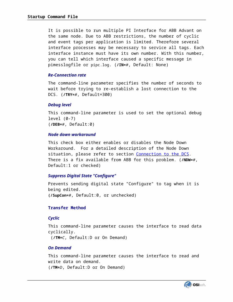
Step DescriptionIF2_State(IF-Node2) [UFO2_STATE:#] IF_State
5. Test the configuration.After configuring the shared file and the interface and PI tags, the interface should be ready to run.See Troubleshooting UniInt Failover for help resolving Failover issues.1. Start the primary interface interactively without buffering.2. Verify a successful interface start by reviewing the pipc.log file. The log file will
contain messages that indicate the failover state of the interface. A successful start with only a single interface copy running will be indicated by an informational message stating “UniInt failover: Interface in the “Primary” state and actively sending data to PI. Backup interface not available.” If the interface has failed to start, an error message will appear in the log file. For details relating to informational and error messages, refer to the Messages section below.
3. Verify data on the PI Server using available PI tools. The Active ID control tag on the PI Server must be set to the value of
the running copy of the interface as defined by the /UFO_ID startup command-line parameter.
The Heartbeat control tag on the PI Server must be changing values at a rate specified by the /UFO_Interval startup command-line parameter.
4. Stop the primary interface.5. Start the backup interface interactively without buffering. Notice that this copy will
become the primary because the other copy is stopped.6. Repeat steps 2, 3, and 4.7. Stop the backup interface.8. Start buffering.9. Start the primary interface interactively.10. Once the primary interface has successfully started and is collecting data, start the
backup interface interactively.11. Verify that both copies of the interface are running in a failover configuration.
Review the pipc.log file for the copy of the interface that was started first. The log file will contain messages that indicate the failover state of the interface. The state of this interface must have changed as indicated with an informational message stating “UniInt failover: Interface in the “Primary” state and actively sending data to PI. Backup interface available.” If the interface has not changed to this state, browse the log file for error messages. For details relating to informational and error messages, refer to the Messages section below.
Review the pipc.log file for the copy of the interface that was started last. The log file will contain messages that indicate the failover state of the interface. A successful start of the interface will be indicated by an informational message stating “UniInt failover: Interface in the “Backup” state.” If the interface has failed to start, an error message will appear in the log file. For details relating to informational and error messages, refer to the Messages section below.
12. Verify data on the PI Server using available PI tools. The Active ID control tag on the PI Server must be set to the value of
the running copy of the interface that was started first as defined by the /UFO_ID startup command-line parameter.
PI Interface for ABB IMS Advant

UniInt Failover Configuration
Step Description
The Heartbeat control tags for both copies of the interface on the PI Server must be changing values at a rate specified by the /UFO_Interval startup command-line parameter or the scan class which the points have been built against.
13. Test Failover by stopping the primary interface.14. Verify the backup interface has assumed the role of primary by searching the
pipc.log file for a message indicating the backup interface has changed to the “UniInt failover: Interface in the “Primary” state and actively sending data to PI. Backup interface not available.” The backup interface is now considered primary and the previous primary interface is now backup.
15. Verify no loss of data in PI. There may be an overlap of data due to the queuing of data. However, there must be no data loss.
16. Start the backup interface. Once the primary interface detects a backup interface, the primary interface will now change state indicating “UniInt failover: Interface in the “Primary” state and actively sending data to PI. Backup interface available.” In the pipc.log file.
17. Verify the backup interface starts and assumes the role of backup. A successful start of the backup interface will be indicated by an informational message stating “UniInt failover: Interface in “Backup state.” Since this is the initial state of the interface, the informational message will be near the beginning of the start sequence of the pipc.log file.
18. Test failover with different failure scenarios (e.g. loss of PI connection for a single interface copy). UniInt failover guarantees no data loss with a single point of failure. Verify no data loss by checking the data in PI and on the data source.
19. Stop both copies of the interface, start buffering, start each interface as a service.20. Verify data as stated above.21. To designate a specific interface as primary. Set the Active ID point on the Data
Source Server of the desired primary interface as defined by the /UFO_ID startup command-line parameter.

Configuring UniInt Failover through a Shared File (Phase 2)
Start-Up Parameters
Note: The /stopstat parameter is disabled if the interface is running in a UniInt failover configuration. Therefore, the digital state, digstate, will not be written to each PI Point when the interface is stopped. This prevents the digital state being written to PI Points while a redundant system is also writing data to the same PI Points. The /stopstat parameter is disabled even if there is only one interface active in the failover configuration.
The following table lists the start-up parameters used by UniInt Failover Phase 2. All of the parameters are required except the /UFO_Interval startup parameter. See the table below for further explanation.
Parameter Required/Optional
Description Value/Default
/UFO_ID=# Required Failover ID for IF-Node1This value must be different from the failover ID of IF-Node2.
Any positive, non-zero integer / 1
Required Failover ID for IF-Node2This value must be different from the failover ID of IF-Node1.
Any positive, non-zero integer / 2
/UFO_OtherID=# Required Other Failover ID for IF-Node1The value must be equal to the Failover ID configured for the interface on IF-Node2.
Same value as Failover ID for IF-Node2 / 2
Required Other Failover ID for IF-Node2The value must be equal to the Failover ID configured for the interface on IF-Node1.
Same value as Failover ID for IF-Node1 / 1
/UFO_Sync=path/[filename]
Required for Phase 2 synchronization
The Failover File Synchronization file path and optional filename specify the path to the shared file used for failover synchronization and an optional filename used to specify a user defined filename in lieu of the default filename.The path to the shared file directory can be a fully qualified machine name and directory, a mapped drive letter, or a local path if the shared file is on one of the interface nodes. The path must be terminated by a slash ( / ) or backslash ( \ ) character. If no terminating slash is found, in the /UFO_Sync parameter, the interface interprets the final character string as an optional filename.The optional filename can be any valid filename. If the file does not
Any valid pathname / any valid filenameThe default filename is generated as executablename_pointsource_interfaceID.dat
PI Interface for ABB IMS Advant
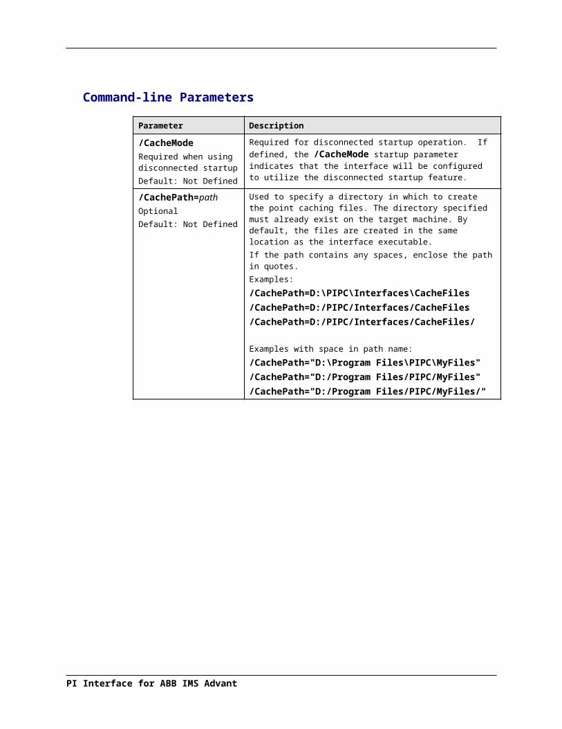
UniInt Failover Configuration
Parameter Required/Optional
Description Value/Default
exist, the first interface to start attempts to create the file.Note: If using the optional filename, do not supply a terminating slash or backslash character.If there are any spaces in the path or filename, the entire path and filename must be enclosed in quotes.Note: If you use the backslash and path separators and enclose the path in double quotes, the final backslash must be a double backslash (\\). Otherwise the closing double quote becomes part of the parameter instead of a parameter separator.Each node in the failover configuration must specify the same path and filename and must have read, write, and file creation rights to the shared directory specified by the path parameter.The service that the interface runs against must specify a valid logon user account under the “Log On” tab for the service properties.
/UFO_Type=type Required The Failover Type indicates which type of failover configuration the interface will run. The valid types for failover are HOT, WARM, and COLD configurations.If an interface does not supported the requested type of failover, the interface will shutdown and log an error to the pipc.log file stating the requested failover type is not supported.
COLD|WARM|HOT / COLD
/UFO_Interval=# Optional Failover Update IntervalSpecifies the heartbeat Update Interval in milliseconds and must be the same on both interface computers.This is the rate at which UniInt updates the Failover Heartbeat tags as well as how often UniInt checks on the status of the other copy of the interface.
50 – 20000 / 5000

Parameter Required/Optional
Description Value/Default
/Host=server Required Host PI Server for exceptions and PI point updatesThe value of the /Host startup parameter depends on the PI Server configuration. If the PI Server is not part of a collective, the value of /Host must be identical on both interface computers.If the redundant interfaces are being configured to send data to a PI Server collective, the value of the /Host parameters on the different interface nodes should equal to different members of the collective.This parameter ensures that outputs continue to be sent to the data source if one of the PI Servers becomes unavailable for any reason.
For IF-Node1PrimaryPI / NoneFor IF-Node2SecondaryPI / None
Failover Control Points
The following table describes the points that are required to manage failover. In Phase 2 Failover, these points are located in a data file shared by the primary and backup interfaces.
OSIsoft recommends that you locate the shared file on a dedicated server that has no other role in data collection. This avoids potential resource contention and processing degradation if your system monitors a large number of data points at a high frequency.
Point Description Value / DefaultActiveID Monitored by the interfaces to determine which
interface is currently sending data to PI. ActiveID must be initialized so that when the interfaces read it for the first time, it is not an error.ActiveID can also be used to force failover. For example, if the current primary is IF-Node 1 and ActiveID is 1, you can manually change ActiveID to 2. This causes the interface at IF-Node2 to transition to the primary role and the interface at IF-Node1 to transition to the backup role.
From 0 to the highest interface Failover ID number / None)Updated by the redundant interfacesCan be changed manually to initiate a manual failover
Heartbeat 1 Updated periodically by the interface on IF-Node1. The interface on IF-Node2 monitors this value to determine if the interface on IF-Node1 has become unresponsive.
Values range between 0 and 31 / NoneUpdated by the interface on IF-Node1
Heartbeat 2 Updated periodically by the interface on IF-Node2. The interface on IF-Node1 monitors this value to determine if the interface on IF-Node2 has become unresponsive.
Values range between 0 and 31 / NoneUpdated by the interface on IF-Node2
PI Interface for ABB IMS Advant

UniInt Failover Configuration
PI Tags
The following tables list the required UniInt Failover Control PI tags, the values they will receive, and descriptions.
Active_ID Tag Configuration
Attributes ActiveID
Tag <Intf>_ActiveIDCompMax 0ExDesc [UFO2_ActiveID]
Location1 Match # in /id=#Location5 Optional, Time in min to wait for backup
to collect data before failing over.
PointSource Match x in /ps=xPointType Int32
Shutdown 0
Step 1
Heartbeat and Device Status Tag Configuration
Attribute Heartbeat 1 Heartbeat 2 DeviceStatus 1 DeviceStatus 2
Tag <HB1> <HB2> <DS1> <DS2>
ExDesc[UFO2_Heartbeat:#]Match # in /UFO_ID=#
[UFO2_Heartbeat:#]Match # in /UFO_OtherID=#
[UFO2_DeviceStat:#]Match # in /UFO_ID=#
[UFO2_DeviceStat:#]Match # in /UFO_OtherID=#
Location1 Match # in /id=# Match # in /id=# Match # in /id=# Match # in /id=#
Location5 Optional, Time in min to wait for backup to collect data before failing over.
Optional, Time in min to wait for backup to collect data before failing over.
Optional, Time in min to wait for backup to collect data before failing over.
Optional, Time in min to wait for backup to collect data before failing over.
Point Source
Match x in /ps=x Match x in /ps=x Match x in /ps=x Match x in /ps=x
PointType int32 int32 int32 int32
Shutdown 0 0 0 0
Step 1 1 1 1
Interface State Tag Configuration
Attribute Primary Backup
Tag <Tagname1> <Tagname2>
CompMax 0 0
DigitalSet UFO_State UFO_State
ExDesc [UFO2_State:#](Match /UFO_ID=# on primary node)
[UFO2_State:#](Match /UFO_ID=# on backup node)
Location1 Match # in /id=# Same as for primary node
PointSource Match x in /ps=x Same as for primary node

Attribute Primary BackupPointType digital digital
Shutdown 0 0
Step 1 1
The following table describes the extended descriptor for the above PI tags in more detail.
PI Tag ExDesc Required / Optional
Description Value
[UFO2_ACTIVEID] Required Active ID tagThe ExDesc must start with the case sensitive string: [UFO2_ACTIVEID].The PointSource must match the interfaces’ Pointsource.Location1 must match the ID for the interfaces.Location5 is the COLD failover retry interval in minutes. This can be used to specify how long before an interface retries to connect to the device in a COLD failover configuration. (See the description of COLD failover retry interval for a detailed explanation.)
0 – highest Interface Failover IDUpdated by the redundant interfaces
[UFO2_HEARTBEAT:#](IF-Node1)
Required Heartbeat 1 TagThe ExDesc must start with the case sensitive string: [UFO2_HEARTBEAT:#]The number following the colon (:) must be the Failover ID for the interface running on IF-Node1.The PointSource must match the interfaces’ PointSource.Location1 must match the ID for the interfaces.
0 – 31 / NoneUpdated by the interface on IF-Node1
[UFO2_HEARTBEAT:#](IF-Node2)
Required Heartbeat 2 TagThe ExDesc must start with the case sensitive string: [UFO2_HEARTBEAT:#]The number following the colon (:) must be the Failover ID for the interface running on IF-Node2.The pointsource must match the interfaces’ point source.Location1 must match the id for the interfaces.
0 – 31 / NoneUpdated by the interface on IF-Node2
PI Interface for ABB IMS Advant

UniInt Failover Configuration
PI Tag ExDesc Required / Optional
Description Value
[UFO2_DEVICESTAT:#](IF-Node1)
Required Device Status 1 TagThe ExDesc must start with the case sensitive string: [UFO2_DEVICESTAT:#]The value following the colon (:) must be the Failover ID for the interface running on IF-Node1The PointSource must match the interfaces’ PointSource.Location1 must match the ID for the interfaces.A lower value is a better status and the interface with the lower status will attempt to become the primary interface.The failover 1 device status tag is very similar to the UniInt Health Device Status tag except the data written to this tag are integer values. A value of 0 is good and a value of 99 is OFF. Any value between these two extremes may result in a failover. The interface client code updates these values when the health device status tag is updated.
0 – 99 / NoneUpdated by the interface on IF-Node1
[UFO2_DEVICESTAT:#](IF-Node2)
Required Device Status 2 TagThe ExDesc must start with the case sensitive string: [UFO2_DEVICESTAT:#]The number following the colon (:) must be the Failover ID for the interface running on IF-Node2The PointSource must match the interfaces’ PointSource.Location1 must match the ID for the interfaces.A lower value is a better status and the interface with the lower status will attempt to become the primary interface.
0 – 99 / NoneUpdated by the interface on IF-Node2
[UFO2_STATE:#](IF-Node1)
Optional State 1 TagThe ExDesc must start with the case sensitive string: [UFO2_STATE:#]The number following the colon (:) must be the Failover ID for the interface running on IF-Node1The failover state tag is recommended.The failover state tags are digital tags assigned to a digital state set with the following values.0 = Off: The interface has been shut down.1 = Backup No Data Source: The
0 – 5 / NoneNormally updated by the interface currently in the primary role.

PI Tag ExDesc Required / Optional
Description Value
interface is running but cannot communicate with the data source.2 = Backup No PI Connection: The interface is running and connected to the data source but has lost its communication to the PI Server.3 = Backup: The interface is running and collecting data normally and is ready to take over as primary if the primary interface shuts down or experiences problems.4 = Transition: The interface stays in this state for only a short period of time. The transition period prevents thrashing when more than one interface attempts to assume the role of primary interface.5 = Primary: The interface is running, collecting data and sending the data to PI.
[UFO2_STATE:#](IF-Node2)
Optional State 2 TagThe ExDesc must start with the case sensitive string: [UFO2_STATE:#]The number following the colon (:) must be the Failover ID for the interface running on IF-Node2The failover state tag is recommended.
Normally updated by the interface currently in the Primary state.Values range between 0 and 5. See description of State 1 tag.
PI Interface for ABB IMS Advant

UniInt Failover Configuration
Detailed Explanation of Synchronization through a Shared File (Phase 2)
In a shared file failover configuration, there is no direct failover control information passed between the data source and the interface. This failover scheme uses five PI tags to control failover operation, and all failover communication between primary and backup interfaces passes through a shared data file.
Once the interface is configured and running, the ability to read or write to the PI tags is not required for the proper operation of failover. This solution does not require a connection to the PI Server after initial startup because the control point data are set and monitored in the shared file. However, the PI tag values are sent to the PI Server so that you can monitor them with standard OSIsoft client tools.
You can force manual failover by changing the ActiveID on the data source to the backup failover ID.
The figure above shows a typical network setup in the normal or steady state. The solid magenta lines show the data path from the interface nodes to the shared file used for failover synchronization. The shared file can be located anywhere in the network as long as both interface nodes can read, write, and create the necessary file on the shared file machine. OSIsoft strongly recommends that you put the file on a dedicated file server that has no other role in the collection of data.
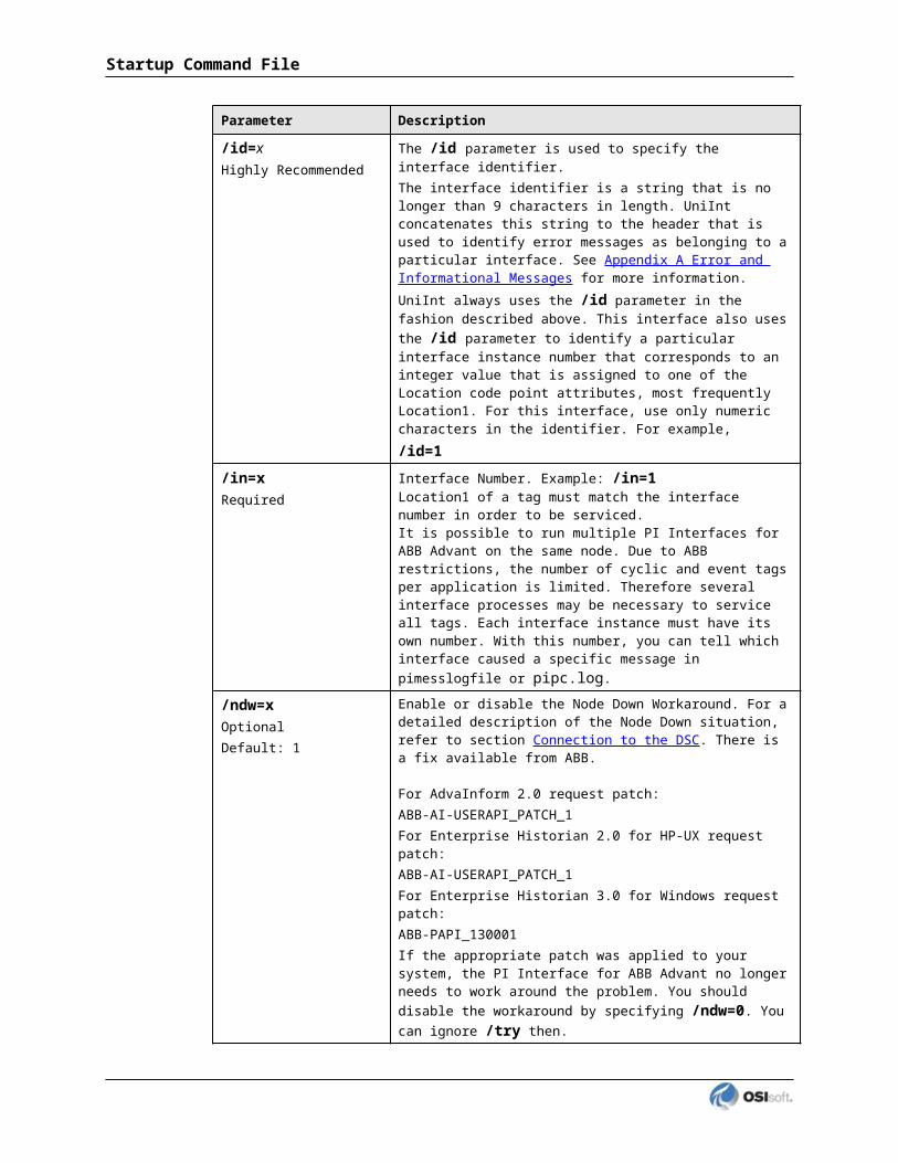
The major difference between synchronizing the interfaces through the data source (Phase 1) and synchronizing the interfaces through the shared file (Phase 2) is where the control data is located. When synchronizing through the data source, the control data is acquired directly from the data source. We assume that if the primary interface cannot read the failover control points, then it cannot read any other data. There is no need for a backup communications path between the control data and the interface.
When synchronizing through a shared file, however, we cannot assume that loss of control information from the shared file implies that the primary interface is down. We must account for the possible loss of the path to the shared file itself and provide an alternate control path to determine the status of the primary interface. For this reason, if the shared file is unreachable for any reason, the interfaces use the PI Server as an alternate path to pass control data.
When the backup interface does not receive updates from the shared file, it cannot tell definitively why the primary is not updating the file, whether the path to the shared file is down, whether the path to the data source is down, or whether the interface itself is having problems. To resolve this uncertainty, the backup interface uses the path to the PI Server to determine the status of the primary interface. If the primary interface is still communicating with the PI Server, than failover to the backup is not required. However, if the primary interface is not posting data to the PI Server, then the backup must initiate failover operations.
The primary interface also monitors the connection with the shared file to maintain the integrity of the failover configuration. If the primary interface can read and write to the shared file with no errors but the backup control information is not changing, then the backup is experiencing some error condition. To determine exactly where the problem exists, the primary interface uses the path to PI to establish the status of the backup interface. For example, if the backup interface controls indicate that it has been shutdown, it may have been restarted and is now experiencing errors reading and writing to the shared file. Both primary and backup interfaces must always check their status through PI to determine if one or the other is not updating the shared file and why.
Steady State Operation
Steady state operation is considered the normal operating condition. In this state, the primary interface is actively collecting data and sending its data to PI. The primary interface is also updating its heartbeat value; monitoring the heartbeat value for the backup interface, checking the active ID value, and checking the device status for the backup interface every failover update interval on the shared file. Likewise, the backup interface is updating its heartbeat value; monitoring the heartbeat value for the primary interface, checking the active ID value, and checking the device status for the primary interface every failover update interval on the shared file. As long as the heartbeat value for the primary interface indicates that it is operating properly, the ActiveID has not changed, and the device status on the primary interface is good, the backup interface will continue in this mode of operation.
An interface configured for hot failover will have the backup interface actively collecting and queuing data but not sending that data to PI. An interface for warm failover in the backup role is not actively collecting data from the data source even though it may be configured with PI tags and may even have a good connection to the data source. An interface configured for cold failover in the backup role is not connected to the data source and upon initial startup will not have configured PI tags.
PI Interface for ABB IMS Advant

UniInt Failover Configuration
The interaction between the interface and the shared file is fundamental to failover. The discussion that follows only refers to the data written to the shared file. However, every value written to the shared file is echoed to the tags on the PI Server. Updating of the tags on the PI Server is assumed to take place unless communication with the PI Server is interrupted. The updates to the PI Server will be buffered by bufserv or BufSS in this case.
In a hot failover configuration, each interface participating in the failover solution will queue three failover intervals worth of data to prevent any data loss. When a failover occurs, there may be a period of overlapping data for up to 3 intervals. The exact amount of overlap is determined by the timing and the cause of the failover and may be different every time. Using the default update interval of 5 seconds will result in overlapping data between 0 and 15 seconds. The no data loss claim for hot failover is based on a single point of failure. If both interfaces have trouble collecting data for the same period of time, data will be lost during that time.
As mentioned above, each interface has its own heartbeat value. In normal operation, the Heartbeat value on the shared file is incremented by UniInt from 1 – 15 and then wraps around to a value of 1 again. UniInt increments the heartbeat value on the shared file every failover update interval. The default failover update interval is 5 seconds. UniInt also reads the heartbeat value for the other interface copy participating in failover every failover update interval. If the connection to the PI Server is lost, the value of the heartbeat will be incremented from 17 – 31 and then wrap around to a value of 17 again. Once the connection to the PI Server is restored, the heartbeat values will revert back to the 1 – 15 range. During a normal shutdown process, the heartbeat value will be set to zero.
During steady state, the ActiveID will equal the value of the failover ID of the primary interface. This value is set by UniInt when the interface enters the primary state and is not updated again by the primary interface until it shuts down gracefully. During shutdown, the primary interface will set the ActiveID to zero before shutting down. The backup interface has the ability to assume control as primary even if the current primary is not experiencing problems. This can be accomplished by setting the ActiveID tag on the PI Server to the ActiveID of the desired interface copy.
As previously mentioned, in a hot failover configuration the backup interface actively collects data but does not send its data to PI. To eliminate any data loss during a failover, the backup interface queues data in memory for three failover update intervals. The data in the queue is continuously updated to contain the most recent data. Data older than three update intervals is discarded if the primary interface is in a good status as determined by the backup. If the backup interface transitions to the primary, it will have data in its queue to send to PI. This queued data is sent to PI using the same function calls that would have been used had the interface been in a primary state when the function call was received from UniInt. If UniInt receives data without a timestamp, the primary copy uses the current PI time to timestamp data sent to PI. Likewise, the backup copy timestamps data it receives without a timestamp with the current PI time before queuing its data. This preserves the accuracy of the timestamps.

Failover Configuration Using PI ICU
The use of the PI ICU is the recommended and safest method for configuring the interface for UniInt failover. With the exception of the notes described in this section, the interface shall be configured with the PI ICU as described in the Configuring the Interface with PI ICU section of this manual.
Note: With the exception of the /UFO_ID and /UFO_OtherID startup command-line parameters, the UniInt failover scheme requires that both copies of the interface have identical startup command files. This requirement causes the PI ICU to produce a message when creating the second copy of the interface stating that the “PS/ID combo already in use by the interface” as shown in Figure 2 below. Ignore this message and click the Add button.
Create the Interface Instance with PI ICU
If the interface does not already exist in the ICU it must first be created. The procedure for doing this is the same as for non-failover interfaces. When configuring the second instance for UniInt Failover the Point Source and Interface ID # boxes will be in yellow and a message will be displayed saying this is already in use. This should be ignored.
Figure 2: PI ICU configuration screen shows that the “PS/ID combo is already in use by the interface.” The user must ignore the yellow boxes, which indicate errors, and click the Add button to configure the interface for failover.
PI Interface for ABB IMS Advant

UniInt Failover Configuration
Configuring the UniInt Failover Startup Parameters with PI ICU
There are three interface startup parameters that control UniInt failover: /UFO_ID, /UFO_OtherID, and /UFO_Interval. The UFO stands for UniInt Failover. The /UFO_ID and /UFO_OtherID parameters are required for the interface to operate in a failover configuration, but the /UFO_Interval is optional. Each of these parameters is described in detail in Configuring UniInt Failover through a Shared File (Phase 2) section and Start-Up Parameters
Figure 3: The figure above illustrates the PI ICU failover configuration screen showing the UniInt failover startup parameters (Phase 2). This copy of the interface defines its Failover ID as 2 (/UFO_ID=2) and the other Interfaces Failover ID as 1 (/UFO_OtherID=1). The other failover interface copy must define its Failover ID as 1 (/UFO_ID=1) and the other Interface Failover ID as 2 (/UFO_OtherID=2) in its ICU failover configuration screen. It also defines the location and name of the synchronization file as well as the type of failover as COLD.
Creating the Failover State Digital State Set
The UFO_State digital state set is used in conjunction with the failover state digital tag. If the UFO_State digital state set has not been created yet, it can be created using either the Failover page of the ICU (1.4.1.0 or greater) or the Digital States plug-in in the SMT 3 Utility (3.0.0.7 or greater).

Using the PI ICU Utility to create Digital State Set
To use the UniInt Failover page to create the UFO_State digital state set, right-click on any of the failover tags in the tag list and then click the Create UFO_State Digital Set on Server XXXXXX… command, where XXXXXX is the PI Server where the points will be or are created.
This command will be unavailable if the UFO_State digital state set already exists on the XXXXXX PI Server.
Using the PI SMT 3 Utility to create Digital State Set
Optionally the Export UFO_State Digital Set (.csv) command on the shortcut menu can be selected to create a comma-separated file to be imported via the System Management Tools (SMT3) (version 3.0.0.7 or higher) or use the UniInt_Failover_DigitalSet_UFO_State.csv file included in the installation kit.
The procedure below outlines the steps necessary to create a digital set on a PI Server using the Import from File command found in the SMT3 application. The procedure assumes the user has a basic understanding of the SMT3 application.
1. Open the SMT3 application.
2. Select the appropriate PI Server from the PI Servers window. If the desired server is not listed, add it using the PI Connection Manager. A view of the SMT application is shown in Figure 4 below.
3. From the System Management Plug-Ins window, expand Points then select Digital States. A list of available digital state sets will be displayed in the main window for the selected PI Server. Refer to Figure 4 below.
4. In the main window, right-click on the desired server and select the Import from File command. Refer to Figure 4 below.
PI Interface for ABB IMS Advant

UniInt Failover Configuration
Figure 4: PI SMT application configured to import a digital state set file. The PI Servers window shows the “localhost” PI Server selected along with the System Management Plug-Ins window showing the Digital States Plug-In as being selected. The digital state set file can now be imported by selecting the Import from File command.
5. Navigate to and select the UniInt_Failover_DigitalSet_UFO_State.csv file for import using the Browse icon on the display. Select the desired Overwrite Options. Refer to Figure 5 below.
Figure 5: PI SMT application Import Digital Set(s) window. This view shows the UniInt_Failover_DigitalSet_UFO_State.csv file as being selected for import. Select the desired Overwrite Options by choosing the appropriate option button.
6. Click on the OK button. Refer to Figure 5 above.
7. The UFO_State digital set is created as shown in Figure 6 below.
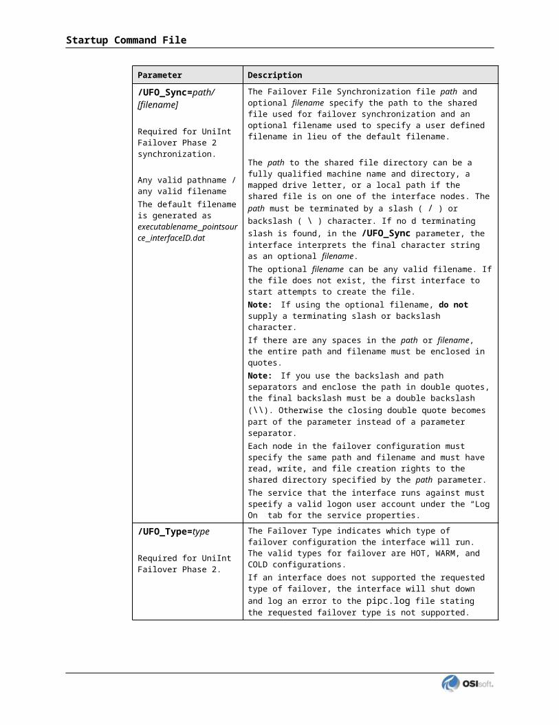
Figure 6: The PI SMT application showing the UFO_State digital set created on the “localhost” PI Server.
PI Interface for ABB IMS Advant

UniInt Failover Configuration
Creating the UniInt Failover Control and Failover State Tags (Phase 2)
The ICU can be used to create the UniInt Failover Control and State Tags.
To use the ICU Failover page to create these tags simply right click any of the failover tags in the tag list and click the Create all points (UFO Phase 2) command.
If this menu choice is unavailable, it is because the UFO_State digital state set has not been created on the PI Server yet. Create UFO_State Digital Set on Server xxxxxxx… on the shortcut menu can be used to create that digital state set. After this has been done then the Create all points (UFO Phase2) command should be available.
Once the failover control and failover state tags have been created the Failover page of the ICU should look similar to the illustration below.

Chapter 11. Interface Node Clock
Windows
Make sure that the time and time zone settings on the computer are correct. To confirm, run the Date/Time applet located in the Windows Control Panel. If the locale where the interface node resides observes Daylight Saving Time, check the Automatically adjust clock for daylight saving changes box. For example,
In addition, make sure that the TZ environment variable is not defined. All of the currently defined environment variables can be viewed by opening a Command Prompt window and typing set. That is,C:> set
Confirm that TZ is not in the resulting list. If it is, run the System applet of the Control Panel, click the Environment Variables button under the Advanced tab, and remove TZ from the list of environment variables.
HP-UX
The correct time and time zone must be configured on the interface node. Also, the interface node should be configured to automatically adjust for daylight saving time for locations that
PI Interface for ABB IMS Advant

use daylight saving time. The correct local settings should be used even if the interface node runs in a different time zone than the PI Server node.
Note: If the HP-UX Interface Node does not observe DST, this is not supported.
PI Interface for ABB IMS Advant

Chapter 12. Security
Windows and UNIX
The PI Firewall Database and the PI Proxy Database must be configured so that the interface is allowed to write data to the PI Server. See “Modifying the Firewall Database” and “Modifying the Proxy Database” in the PI Server manuals.
Note that the Trust Database, which is maintained by the Base Subsystem, replaces the Proxy Database used prior to PI version 3.3. The Trust Database maintains all the functionality of the proxy mechanism while being more secure.
See “Trust Login Security” in the chapter “Managing Security” of the PI Server System Management Guide.
If the interface cannot write data to the PI Server because it has insufficient privileges, a -10401 error will be reported in the pipc.log file. If the interface cannot send data to a PI2 Server, it writes a -999 error. See the section Appendix A: Error and Info r mational Messages for additional information on error messaging.
PI Server v3.3 and Higher
Security configuration using piconfigFor PI Server v3.3 and higher, the following example demonstrates how to edit the PI Trust table:
C:\PI\adm> piconfig@table pitrust@mode create@istr Trust,IPAddr,NetMask,PIUsera_trust_name,192.168.100.11,255.255.255.255,piadmin@quit
For the above,
Trust: An arbitrary name for the trust table entry; in the above example,a_trust_name
IPAddr: the IP Address of the computer running the interface; in the above example,192.168.100.11
NetMask: the network mask; 255.255.255.255 specifies an exact match with IPAddr
PIUser: the PI user the interface to be entrusted as; piadmin is usually an appropriate user
PI Interface for ABB IMS Advant

Security Configuring using Trust EditorThe Trust Editor plug-in for PI System Management Tools 3.x may also be used to edit the PI Trust table.
See the PI System Management chapter in the PI Server manual for more details on security configuration.
PI Server v3.2For PI Server v3.2, the following example demonstrates how to edit the PI Proxy table:
C:\PI\adm> piconfig@table pi_gen,piproxy@mode create@istr host,proxyaccountpiapimachine,piadmin@quit
In place of piapimachine, put the name of the interface node as it is seen by the PI Server.
PI Interface for ABB IMS Advant

Chapter 13. Starting / Stopping the Interface on Windows
This section describes starting and stopping the interface once it has been installed as a service. See the UniInt Interface User Manual to run the interface interactively.
Starting Interface as a Service
If the interface was installed as service, it can be started from PI ICU, the Services control panel or with the command:abbimspi.exe /start
To start the interface service with PI ICU, use the button on the PI ICU toolbar.
A message will inform the user of the status of the interface service. Even if the message indicates that the service has started successfully, double check through the Services control panel applet. Services may terminate immediately after startup for a variety of reasons, and one typical reason is that the service is not able to find the command-line parameters in the associated .bat file. Verify that the root name of the .bat file and the .exe file are the same, and that the .bat file and the .exe file are in the same directory. Further troubleshooting of services might require consulting the pipc.log file, Windows Event Viewer, or other sources of log messages. See the section Appendix A: Error and Informational Messages for additional information.
Stopping Interface Running as a Service
If the interface was installed as service, it can be stopped at any time from PI ICU, the Services control panel or with the command:abbimspi.exe/stop
The service can be removed by:abbimspi.exe/remove
To stop the interface service with PI ICU, use the button on the PI ICU toolbar.
PI Interface for ABB IMS Advant

Chapter 14. Starting / Stopping the Interface on UNIX
This section describes starting and stopping the interface as a background process. See the UniInt Interface User Manual to run the interface as a foreground process.
Command-line Syntax for Background Processes
Jobs that are run in the background remain in existence even after the user that has started the process has logged off of the system. The command-line in the abbimspi1.sh start-up command file should begin with nohup and end with &. For example:nohup PI<GenericName>1.exe program_arguments > PI<GenericName>1.log 2>&1 &
The & at the end of the command-line causes the job to be launched in the background. The nohup at the beginning of the command-line causes hang-ups and quits to be ignored. HPUX boxes are notorious for sending hang-up signals to jobs that a user has started when that user logs off. Always execute a background job with nohup, either by incorporating it into the startup command file of the interface or by typing nohup abbimsa1.sh or nohup sh abbimsa1.sh from the terminal. Unless the job is executed with nohup, the hang-up signal will cause the job to be terminated even if it is run in the background.
A job that is started with nohup will have its standard output redirected to the file nohup.out, unless the standard output is redirected to a different file name. On the command-line above, the standard output is redirected with the > director to the file abbimsa1.log.
The optional sequence 2>&1 causes the standard error to be redirected to standard output so that the standard error will also appear in abbimsa1.log. System commands typically send error messages to the standard error. For example, the command:cat nonexistentfile
fails with the error message “cat: cannot open nonexistent file: No such file or directory.” This error message is redirected to the standard error, which is normally seen on the screen.
Typically, messages that interfaces write to the standard output are also written to the $PIHOME/dat/pimesslogfile. To avoid this duplication, the user can redirect the standard output to the null device, which discards the messages. For example:nohup abbimsa1.exe program_arguments > /dev/null &
redirects the standard output to the null device. Initially, it is recommended to use the first command-line example, where the output is redirected to the abbimsa1.log file.
PI Interface for ABB IMS Advant

Terminating Background Processes
First, obtain the process id (PID) of the background job. This is done as follows. First execute the command:ps –ef | grep abbimsa
which produces output similar to:matzen 12788 12707 2 09:55:27 ttys1 0:00 PI<GenericName>1.exe /ps=B
The second column is the pid of the process. That is, 12788 is the PID of the abbimsa1.exe interface in the example above.
The process is then stopped by:kill 12788
The kill command sends the SIGTERM signal to the interface, causing the exit handler to be invoked.
Unless it cannot be avoided, do NOT stop the interface with kill -9 pid. The option -9 causes the SIGKILL signal to be sent to the interface. The exit handler cannot catch this signal. SIGKILL will immediately terminate the process.
Anomalous Background Job Termination
On some platforms, processes that are started in the background will be terminated if one types “control-c” in the same window that the job was started in. If the window in which the interface was started is closed or if the user logs off and logs back on, the user will not be able to accidentally terminate the job in this manner.
PI Interface for ABB IMS Advant

Chapter 15. Buffering
Buffering refers to an interface node’s ability to temporarily store the data that interfaces collect and to forward these data to the appropriate PI Servers. OSIsoft strongly recommends that you enable buffering on your interface nodes. Otherwise, if the interface node stops communicating with the PI Server, you lose the data that your interfaces collect.
The PI SDK installation kit installs two buffering applications: the PI Buffer Subsystem (PIBufss) and the PI API Buffer Server (Bufserv). PIBufss and Bufserv are mutually exclusive; that is, on a particular computer, you can run only one of them at any given time.
If you have PI Servers that are part of a PI collective, PIBufss supports n-way buffering. N-way buffering refers to the ability of a buffering application to send the same data to each of the PI Servers in a PI collective. (Bufserv also supports n-way buffering, but OSIsoft recommends that you run PIBufss instead.)
Which Buffering Application to Use
You should use PIBufss whenever possible because it offers better throughput than Bufserv. In addition, if the interfaces on an interface node are sending data to a PI collective, PIBufss guarantees identical data in the archive records of all the PI Servers that are part of that collective.
You can use PIBufss only under the following conditions:
the PI Server version is at least 3.4.375.x; and
all of the interfaces running on the interface node send data to the same PI Server or to the same PI collective.
If any of the following scenarios apply, you must use Bufserv:
the PI Server version is earlier than 3.4.375.x; or
the interface node runs multiple interfaces, and these interfaces send data to multiple PI Servers that are not part of a single PI collective.
If an interface node runs multiple interfaces, and these interfaces send data to two or more PI collectives, then neither PIBufss nor Bufserv is appropriate. The reason is that PIBufss and Bufserv can buffer data only to a single collective. If you need to buffer to more than one PI collective, you need to use two or more interface nodes to run your interfaces.
It is technically possible to run Bufserv on the PI Server Node. However, OSIsoft does not recommend this configuration.
PI Interface for ABB IMS Advant

How Buffering Works
A complete technical description of PIBufss and Bufserv is beyond the scope of this document. However, the following paragraphs provide some insights on how buffering works.
When an interface node has buffering enabled, the buffering application (PIBufss or Bufserv) connects to the PI Server. It also creates shared memory storage.
When an interface program makes a PI API function call that writes data to the PI Server (for example, pisn_sendexceptionqx()), the PI API checks whether buffering is enabled. If it is, these data writing functions do not send the interface data to the PI Server. Instead, they write the data to the shared memory storage that the buffering application created.
The buffering application (either Bufserv or PIBufss) in turn
reads the data in shared memory, and
if a connection to the PI Server exists, sends the data to the PI Server; or
if there is no connection to the PI Server, continues to store the data in shared memory (if shared memory storage is available) or writes the data to disk (if shared memory storage is full).
When the buffering application re-establishes connection to the PI Server, it writes to the PI Server the interface data contained in both shared memory storage and disk.
(Before sending data to the PI Server, PIBufss performs further tasks such as data validation and data compression, but the description of these tasks is beyond the scope of this document.)
When PIBufss writes interface data to disk, it writes to multiple files. The names of these buffering files are PIBUFQ_*.DAT.
When Bufserv writes interface data to disk, it writes to a single file. The name of its buffering file is APIBUF.DAT.
As a previous paragraph indicates, PIBufss and Bufserv create shared memory storage at startup. These memory buffers must be large enough to accommodate the data that an interface collects during a single scan. Otherwise, the interface may fail to write all its collected data to the memory buffers, resulting in data loss. The buffering configuration section of this chapter provides guidelines for sizing these memory buffers.
When buffering is enabled, it affects the entire interface node. That is, you do not have a scenario whereby the buffering application buffers data for one interface running on an interface node but not for another interface running on the same interface node.
Buffering and PI Server Security
After you enable buffering, it is the buffering application – and not the interface program – that writes data to the PI Server. If the PI Server’s trust table contains a trust entry that allows all applications on an interface node to write data, then the buffering application is able write data to the PI Server.
However, if the PI Server contains an interface-specific PI Trust entry that allows a particular interface program to write data, you must have a PI Trust entry specific to buffering. The following are the appropriate entries for the Application Name field of a PI Trust entry:
PI Interface for ABB IMS Advant

Buffering Application Application Name field for PI TrustPI Buffer Subsystem PIBufss.exe
PI API Buffer Server APIBE (if the PI API is using 4 character process names)APIBUF (if the PI API is using 8 character process names)
To use a process name greater than 4 characters in length for a trust application name, use the LONGAPPNAME=1 in the PIClient.ini file.
Enabling Buffering on an Interface Node with the ICU
The ICU allows you to select either PIBufss or Bufserv as the buffering application for your interface node. Run the ICU and select Tools > Buffering.
Choose Buffer Type
To select PIBufss as the buffering application, choose Enable buffering with PI Buffer Subsystem.
To select Bufserv as the buffering application, choose Enable buffering with API Buffer Server.
If a warning message such as the following appears, click Yes.
PI Interface for ABB IMS Advant

Buffering
Buffering Settings
There are a number of settings that affect the operation of PIBufss and Bufserv. The Buffering Settings section allows you to set these parameters. If you do not enter values for these parameters, PIBufss and Bufserv use default values.
PIBufssFor PIBufss, the paragraphs below describe the settings that may require user intervention. Please contact OSIsoft Technical Support for assistance in further optimizing these and all remaining settings.
Primary and Secondary Memory Buffer Size (Bytes)This is a key parameter for buffering performance. The sum of these two memory buffer sizes must be large enough to accommodate the data that an interface collects during a single scan. A typical event with a Float32 point type requires about 25 bytes. If an interface writes data to 5,000 points, it can potentially send 125,000 bytes (25 * 5000) of data in one scan. As a result, the size of each memory buffer should be 62,500 bytes.
The default value of these memory buffers is 32,768 bytes. OSIsoft recommends that these two memory buffer sizes should be increased to the maximum of 2000000 for the best buffering performance.
Send rate (milliseconds)Send rate is the time in milliseconds that PIBufss waits between sending up to the Maximum transfer objects (described below) to the PI Server. The default value is 100. The valid range is 0 to 2,000,000.
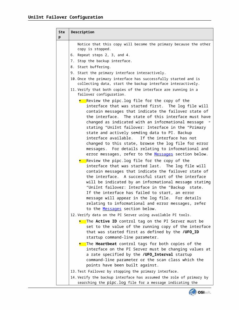
Maximum transfer objectsMaximum transfer objects is the maximum number of events that PIBufss sends between each Send rate pause. The default value is 500. The valid range is 1 to 2,000,000.
Event Queue File Size (Mbytes)This is the size of the event queue files. PIBufss stores the buffered data to these files. The default value is 32. The range is 8 to 131072 (8 to 128 Gbytes). Please see the section entitled "Queue File Sizing" in the PIBufss.chm file for details on how to appropriately size the event queue files.
Event Queue PathThis is the location of the event queue file. The default value is [PIHOME]\DAT.
For optimal performance and reliability, OSIsoft recommends that you place the PIBufss event queue files on a different drive/controller from the system drive and the drive with the Windows paging file. (By default, these two drives are the same.)
BufservFor Bufserv, the paragraphs below describe the settings that may require user intervention. Please contact OSIsoft Technical Support for assistance in further optimizing these and all remaining settings.
Maximum buffer file size (KB)This is the maximum size of the buffer file ([PIHOME]\DAT\APIBUF.DAT). When Bufserv cannot communicate with the PI Server, it writes and appends data to this file. When the buffer file reaches this maximum size, Bufserv discards data.
The default value is 2,000,000 KB, which is about 2 GB. The range is from 1 to 2,000,000.
PI Interface for ABB IMS Advant
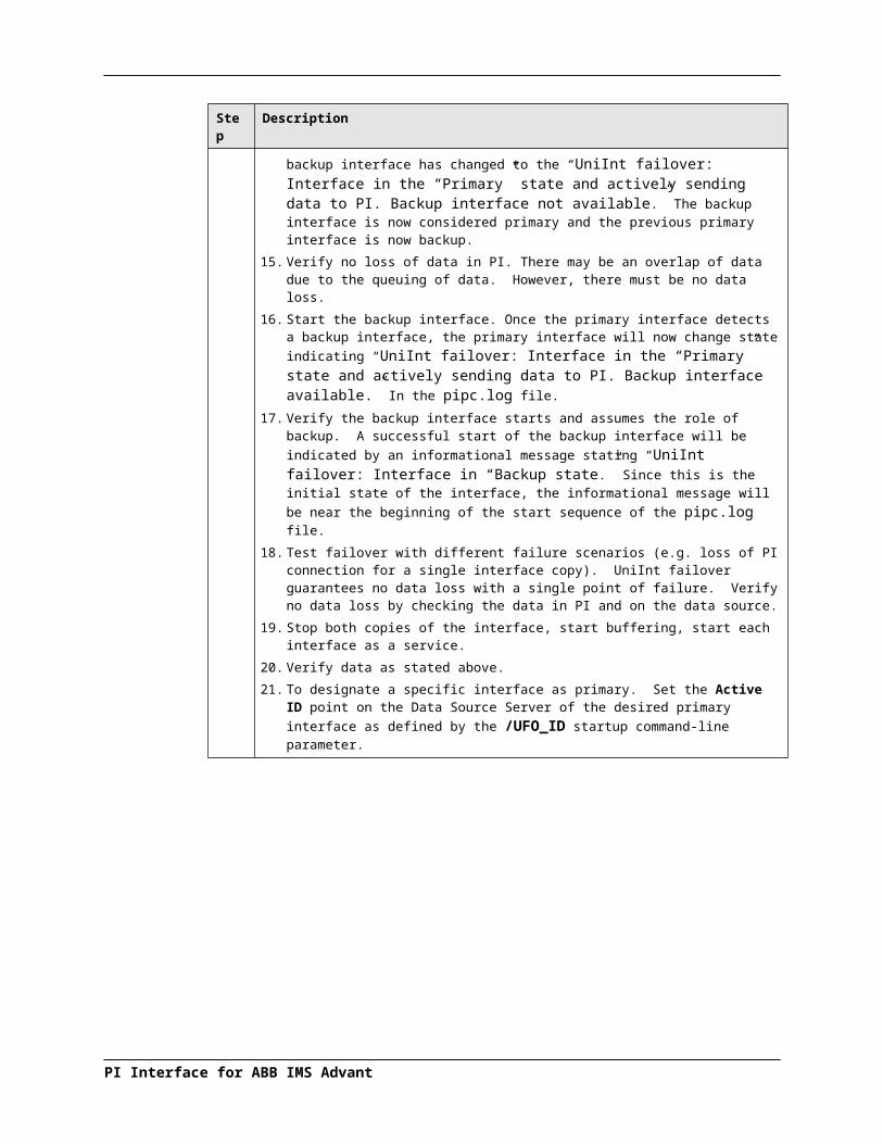
Buffering
Primary and Secondary Memory Buffer Size (Bytes)This is a key parameter for buffering performance. The sum of these two memory buffer sizes must be large enough to accommodate the data that an interface collects during a single scan. A typical event with a Float32 point type requires about 25 bytes. If an interface writes data to 5,000 points, it can potentially send 125,000 bytes (25 * 5000) of data in one scan. As a result, the size of each memory buffer should be 62,500 bytes.
The default value of these memory buffers is 32,768 bytes. OSIsoft recommends that these two memory buffer sizes should be increased to the maximum of 2000000 for the best buffering performance.
Send rate (milliseconds)Send rate is the time in milliseconds that Bufserv waits between sending up to the Maximum transfer objects (described below) to the PI Server. The default value is 100. The valid range is 0 to 2,000,000.
Maximum transfer objectsMax transfer objects is the maximum number of events that Bufserv sends between each Send rate pause. The default value is 500. The valid range is 1 to 2,000,000.
Buffered Servers
The Buffered Servers section allows you to define the PI Servers or PI collective that the buffering application writes data.
PIBufssPIBufss buffers data only to a single PI Server or a PI collective. Select the PI Server or the PI collective from the Buffering to collective/server drop down list box.
The following screen shows that PIBufss is configured to write data to a standalone PI Server named starlight. Notice that the Replicate data to all collective member nodes check box is disabled because this PI Server is not part of a collective. (PIBufss automatically detects whether a PI Server is part of a collective.)

The following screen shows that PIBufss is configured to write data to a PI collective named admiral. By default, PIBufss replicates data to all collective members. That is, it provides n-way buffering.
You can override this option by not checking the Replicate data to all collective member nodes check box. Then, uncheck (or check) the PI Server collective members as desired.
PI Interface for ABB IMS Advant

Buffering
BufservBufserv buffers data to a standalone PI Server, or to multiple standalone PI Servers. (If you want to buffer to multiple PI Servers that are part of a PI collective, you should use PIBufss.)
If the PI Server to which you want Bufserv to buffer data is not in the Server list, enter its name in the Add a server box and click the Add Server button. This PI Server name must be identical to the API Hostname entry:
The following screen shows that Bufserv is configured to write to a standalone PI Server named etamp390. You use this configuration when all the interfaces on the interface node write data to etamp390.
The following screen shows that Bufserv is configured to write to two standalone PI Servers, one named etamp390 and the other one named starlight. You use this configuration when some of the interfaces on the interface node write data to etamp390 and some write to starlight.
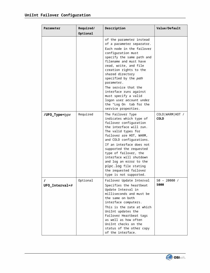
Installing Buffering as a Service
Both the PIBufss and Bufserv applications run as a Service.
PI Buffer Subsystem ServiceUse the PI Buffer Subsystem Service page to configure PIBufss as a Service. This page also allows you to start and stop the PIBufss service.
PIBufss does not require the logon rights of the local administrator account. It is sufficient to use the LocalSystem account instead. Although the screen below shows asterisks for the LocalSystem password, this account does not have a password.
PI Interface for ABB IMS Advant

Buffering
API Buffer Server ServiceUse the API Buffer Server Service page to configure Bufserv as a Service. This page also allows you to start and stop the Bufserv Service
Bufserv version 1.6 and later does not require the logon rights of the local administrator account. It is sufficient to use the LocalSystem account instead. Although the screen below shows asterisks for the LocalSystem password, this account does not have a password.

PI Interface for ABB IMS Advant

Chapter 16. Interface Diagnostics Configuration
The PI Point Configuration chapter provides information on building PI points for collecting data from the device. This chapter describes the configuration of points related to interface diagnostics.
Note: The procedure for configuring interface diagnostics is not specific to this interface. Thus, for simplicity, the instructions and screenshots that follow refer to an interface named ModbusE.
Some of the points that follow refer to a “performance summary interval”. This interval is 8 hours by default. You can change this parameter via the Scan performance summary box in the UniInt – Debug parameter category page:
Scan Class Performance Points
A Scan Class Performance Point measures the amount of time (in seconds) that this interface takes to complete a scan. The interface writes this scan completion time to millisecond resolution. Scan completion times close to 0 indicate that the interface is performing optimally. Conversely, long scan completion times indicate an increased risk of missed or skipped scans. To prevent missed or skipped scans, you should distribute the data collection points among several scan classes.
PI Interface for ABB IMS Advant
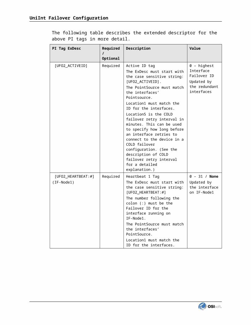
You configure one Scan Class Performance Point for each scan class in this interface. From the ICU, select this interface from the Interface drop-down list and click UniInt-Performance Points in the parameter category pane:
Right click the row for a particular Scan Class # to open the shortcut menu:
You need not restart the interface for it to write values to the Scan Class Performance Points.
To see the current values (snapshots) of the Scan Class Performance Points, right-click and select Refresh Snapshots.
Create / Create AllTo create a Performance Point, right-click the line belonging to the tag to be created, and select Create. Click Create All to create all the Scan Class Performance Points.
DeleteTo delete a Performance Point, right-click the line belonging to the tag to be deleted, and select Delete.
PI Interface for ABB IMS Advant

Correct / Correct AllIf the “Status” of a point is marked “Incorrect”, the point configuration can be automatically corrected by ICU by right-clicking on the line belonging to the tag to be corrected, and selecting Correct. The Performance Points are created with the following PI attribute values. If ICU detects that a Performance Point is not defined with the following, it will be marked Incorrect: To correct all points, click Correct All.
The Performance Points are created with the following PI attribute values:
Attribute Details
Tag Tag name that appears in the list box
Point Source Point Source for tags for this interface, as specified on the first tab
Compressing Off
Excmax 0
Descriptor Interface name + “ Scan Class # Performance Point”
RenameRight-click the line belonging to the tag and select Rename to rename the Performance Point.
Column descriptions
StatusThe Status column in the Performance Points table indicates whether the Performance Point exists for the scan class in the Scan Class # column.
Created – Indicates that the Performance Point does exist
Not Created – Indicates that the Performance Point does not exist
Deleted – Indicates that a Performance Point existed, but was just deleted by the user
Scan Class #The Scan Class column indicates which scan class the Performance Point in the Tagname column belongs to. There will be one scan class in the Scan Class column for each scan class listed in the Scan Classes box on the General page.
TagnameThe Tagname column holds the Performance Point tag name.
PSThis is the point source used for these performance points and the interface.
Location1This is the value used by the interface for the /ID=# point attribute.
ExDescThis is the used to tell the interface that these are performance points and the value is used to corresponds to the /ID=# command line parameter if multiple copies of the same interface are running on the interface node.
PI Interface for ABB IMS Advant

Interface Diagnostics Configuration
SnapshotThe Snapshot column holds the snapshot value of each Performance Point that exists in PI. The Snapshot column is updated when the Performance Points page is selected, and when the interface is first loaded. You may have to scroll to the right to see the snapshots.
Configuring Performance Points on UNIX
Performance point configuration is the same on all operating system platforms. Performance points are configured as follows.
1. Set the extended descriptor to:
PERFORMANCE_POINTor to:PERFORMANCE_POINT=interface_id
where interface_id corresponds to the identifier that is specified with the /id parameter on the startup command-line of the interface. The character string PERFORMANCE_POINT is case insensitive. The interface_id does not need to be specified if there is only one copy of an interface that is associated with a particular point source.
2. Set Location4 to correspond to the scan class whose performance is to be monitored. For example, to monitor scan class 2, set Location4 to 2. See the /f parameter for a description of scan classes.
3. Set the PointSource attribute to correspond to the /ps parameter on the startup command-line of the interface.
4. Set the PointType attribute to float32.
Performance Counters Points
When running as a Service or interactively, this interface exposes performance data via Windows Performance Counters. Such data include items like:
the amount of time that the interface has been running;
the number of points the interface has added to its point list;
the number of tags that are currently updating among others
There are two types or instances of Performance Counters that can be collected and stored in PI Points. The first is (_Total) which is a total for the Performance Counter since the interface instance was started. The other is for individual scan classes (Scan Class x) where x is a particular scan class defined for the interface instance that is being monitored.
OSIsoft’s PI Performance Monitor interface is capable of reading these performance values and writing them to PI points. Please see the Performance Monitor Interface for more information.
If there is no PI Performance Monitor Interface registered with the ICU in the Module Database for the PI Server the interface is sending its data to, you cannot use the ICU to create any interface instance’s Performance Counters Points:
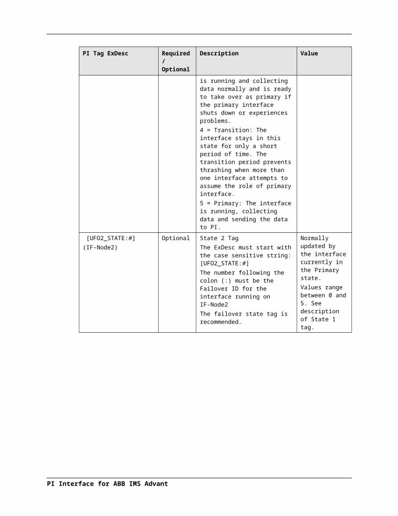
After installing the PI Performance Monitor Interface as a service, select this interface instance from the Interface drop-down list, then click Performance Counters in the parameter categories pane, and right-click on the row containing the Performance Counters Point you wish to create. This will open the shortcut menu:
Click Create to create the Performance Counters Point for that particular row. Click Create All to create all the Performance Counters Points listed which have a status of Not Created.
To see the current values (snapshots) of the created Performance Counters Points, right-click on any row and select Refresh Snapshots.
PI Interface for ABB IMS Advant

Interface Diagnostics Configuration
Note: The PI Performance Monitor Interface – and not this interface – is responsible for updating the values for the Performance Counters Points in PI. So, make sure that the PI Performance Monitor Interface is running correctly.
Performance Counters
In the following lists of Performance Counters the naming convention used will be:
“PerformanceCounterName” (.PerformanceCounterPointSuffix)
The tagname created by the ICU for each Performance Counter point is based on the setting found under the Tools Options Naming Conventions Performance Counter Points. The default for this is “sy.perf.[machine].[if service] followed by the Performance Counter Point suffix.
Performance Counters for both (_Total) and (Scan Class x)
“Point Count” (.point_count)A .point_count Performance Counters Point is available for each scan class of this interface as well as an "(_Total)" for the interface instance.
The .point_count Performance Counters Point indicates the number of PI Points per scan class or the total number for the interface instance. This point is similar to the Health Point [UI_SCPOINTCOUNT] for scan classes and [UI_POINTCOUNT] for totals.
The ICU uses a naming convention such that the tag containing "(Scan Class 1)" (for example, "sy.perf.etamp390.E1(Scan Class 1).point_count") refers to scan class 1, “(Scan Class 2)” refers to scan class 2, and so on. The tag containing "(_Total)" refers to the sum of all scan classes.
“Scheduled Scans: % Missed” (.sched_scans_%missed)A .sched_scans_%missed Performance Counters Point is available for each scan class of this interface as well as an "(_Total)" for the interface instance.
The .sched_scans_%missed Performance Counters Point indicates the percentage of scans the interface missed per scan class or the total number missed for all scan classes since startup. A missed scan occurs if the interface performs the scan one second later than scheduled.
The ICU uses a naming convention such that the tag containing “(Scan Class 1)” (for example, "sy.perf.etamp390.E1(Scan Class 1).sched_scans_%missed") refers to scan class 1, “(Scan Class 2)” refers to scan class 2, and so on. The tag containing “(_Total)” refers to the sum of all scan classes.
“Scheduled Scans: % Skipped” (.sched_scans_%skipped)A .sched_scans_%skipped Performance Counters Point is available for each scan class of this interface as well as an "(_Total)" for the interface instance.
The .sched_scans_%skipped Performance Counters Point indicates the percentage of scans the interface skipped per scan class or the total number skipped for all scan classes since startup. A skipped scan is a scan that occurs at least one scan period after its scheduled time. This point is similar to the [UI_SCSKIPPED] Health Point.

The ICU uses a naming convention such that the tag containing "(Scan Class 1)" (for example, "sy.perf.etamp390.E1(Scan Class 1).sched_scans_%skipped") refers to scan class 1, "(Scan Class 2)" refers to scan class 2, and so on. The tag containing "(_Total)" refers to the sum of all scan classes.
“Scheduled Scans: Scan count this interval” (.sched_scans_this_interval)A .sched_scans_this_interval Performance Counters Point is available for each scan class of this interface as well as an "(_Total)" for the interface instance.
The .sched_scans_this_interval Performance Counters Point indicates the number of scans that the interface performed per performance summary interval for the scan class or the total number of scans performed for all scan classes during the summary interval. This point is similar to the [UI_SCSCANCOUNT] Health Point.
The ICU uses a naming convention such that the tag containing “(Scan Class 1)” (for example, “sy.perf.etamp390.E1(Scan Class 1).sched_scans_this_interval” refers to scan class 1, “(Scan Class 2)” refers to scan class 2, and so on. The tag containing “(_Total)” refers to the sum of all scan classes.
Performance Counters for (_Total) only
“Device Actual Connections” (.Device_Actual_Connections)The .Device_Actual_Connections Performance Counters Point stores the actual number of foreign devices currently connected and working properly out of the expected number of foreign device connections to the interface. This value will always be less than or equal to the Device Expected Connections counter.
“Device Expected Connections” (.Device_Expected_Connections)The .Device_Expected_Connections Performance Counters Point stores the total number of foreign device connections for the interface. This is the expected number of foreign device connections configured that should be working properly at runtime. If the interface can only communicate with 1 foreign device then the value of this counter will always be one. If the interface can support multiple foreign device connections then this is the total number of expected working connections configured for this interface.
“Device Status” (.Device_Status)The .Device_Status Performance Counters Point stores communication information about the interface and the connection to the foreign device(s). The value of this counter is based on the expected connections, actual connections and value of the /PercentUp command line option. If the device status is good then the value is ‘0’. If the device status is bad then the value is ‘1’. If the interface only supports connecting to 1 foreign device then the /PercentUp command line value does not change the results of the calculation. If for example the interface can connect to 10 devices and 5 are currently working then the value of the /PercentUp command line parameter is applied to determine the Device Status. If the value of the /PercentUp command line parameter is set to 50 and at least 5 devices are working then the DeviceStatus will remain good (that is, have a value of zero).
PI Interface for ABB IMS Advant

Interface Diagnostics Configuration
“Failover Status” (.Failover_Status)The .Failover_Status Performance Counters Point stores the failover state of the interface when configured for UniInt failover. The value of the counter will be ‘0’ when the interface is running as the primary interface in the failover configuration. If the interface is running in backup mode then the value of the counter will be '1'.
“Interface up-time (seconds)” (.up_time)The .up_time Performance Counters Point indicates the amount of time (in seconds) that this interface has been running. At startup the value of the counter is zero. The value will continue to increment until it reaches the maximum value for an unsigned integer. Once it reaches this value then it will start back over at zero.
“IO Rate (events/second)” (.io_rates)The .io_rates Performance Counters Point indicates the rate (in event per second) at which this interface writes data to its input tags. (As of UniInt 4.5.0.x and later this performance counters point will no longer be available.)
“Log file message count” (.log_file_msg_count)The .log_file_msg_count Performance Counters Point indicates the number of messages that the interface has written to the log file. This point is similar to the [UI_MSGCOUNT] Health Point.
“PI Status” (PI_Status)The .PI_Status Performance Counters Point stores communication information about the interface and the connection to the PI Server. If the interface is properly communicating with the PI Server then the value of the counter is ‘0’. If the communication to the PI Server goes down for any reason then the value of the counter will be ‘1’. Once the interface is properly communicating with the PI Server again then the value will change back to ‘0’.
“Points added to the interface” (.pts_added_to_interface)The .pts_added_to_interface Performance Counter Point indicates the number of points the interface has added to its point list. This does not include the number of points configured at startup. This is the number of points added to the interface after the interface has finished a successful startup.
“Points edited in the interface”(.pts_edited_in_interface)The .pts_edited_in_interface Performance Counters Point indicates the number of point edits the interface has detected. The interface detects edits for those points whose PointSource attribute matches the /ps= parameter and whose Location1 attribute matches the /id= parameter of the interface.

“Points Good” (.Points_Good)The .Points_Good Performance Counters Point is the number of points that have sent a good current value to PI. A good value is defined as any value that is not a system digital state value. A point can either be Good, In Error, or Stale. The total of Points Good, Points In Error, and Points State will equal the Point Count. There is one exception to this rule. At startup of an interface, the Stale timeout must elapse before the point will be added to the Stale Counter. Therefore the interface must be up and running for at least 10 minutes for all tags to belong to a particular Counter.
“Points In Error” (.Points_In_Error)The .Points_In_Error Performance Counters Point indicates the number of points that have sent a current value to PI that is a system digital state value. Once a point is in the In Error count it will remain in the In Error count until the point receives a new, good value. Points in Error do not transition to the Stale Counter. Only good points become stale.
“Points removed from the interface” (.pts_removed_from_interface)The .pts_removed_from_interface Performance Counters Point indicates the number of points that have been removed from the interface configuration. A point can be removed from the interface when one of the point attributes is updated and the point is no longer a part of the interface configuration. For example, changing the PointSource, Location1, or Scan attribute can cause the tag to no longer be a part of the interface configuration.
“Points Stale 10(min)” (.Points_Stale_10min)The .Points_Stale_10min Performance Counters Point indicates the number of good points that have not received a new value in the last 10 minutes. If a point is Good, then it will remain in the good list until the Stale timeout elapses. At this time if the point has not received a new value within the Stale Period then the point will move from the Good count to the Stale count. Only points that are Good can become Stale. If the point is in the In Error count then it will remain in the In Error count until the error clears. As stated above, the total count of Points Good, Points In Error, and Points Stale will match the Point Count for the interface.
“Points Stale 30(min)” (.Points_Stale_30min)The .Points_Stale_30min Performance Counters Point indicates the number of points that have not received a new value in the last 30 minutes. For a point to be in the Stale 30 minute count it must also be a part of the Stale 10 minute count.
“Points Stale 60(min)” (.Points_Stale_60min)The .Points_Stale_60min Performance Counters Point indicates the number of points that have not received a new value in the last 60 minutes. For a point to be in the Stale 60 minute count it must also be a part of the Stale 10 minute and 30 minute count.
“Points Stale 240(min)” (.Points_Stale_240min)The .Points_Stale_240min Performance Counters Point indicates the number of points that have not received a new value in the last 240 minutes. For a point to be in the Stale 240 minute count it must also be a part of the Stale 10 minute, 30 minute and 60 minute count.
PI Interface for ABB IMS Advant

Interface Diagnostics Configuration
Performance Counters for (Scan Class x) only
“Device Scan Time (milliseconds)” (.Device_Scan_Time)A .Device_Scan_Time Performance Counter Point is available for each scan class of this interface.
The .Device_Scan_Time Performance Counters Point indicates the number of milliseconds the interface takes to read the data from the foreign device and package the data to send to PI. This counter does not include the amount of time to send the data to PI. This point is similar to the [UI_SCINDEVSCANTIME] Health Point.
The ICU uses a naming convention such that the tag containing “(Scan Class 1)” (for example, "sy.perf.etamp390.E1 (Scan Class 1).device_scan _time") refers to scan class 1, “(Scan Class 2) refers to scan class 2, and so on.
“Scan Time (milliseconds)” (.scan_time)A .scan_time Performance Counter Point is available for each scan class of this interface.
The .scan_time Performance Counter Point indicates the number of milliseconds the interface takes to both read the data from the device and send the data to PI. This point is similar to the [UI_SCINSCANTIME] Health Point.
The ICU uses a naming convention such that the tag containing “(Scan Class 1)” (for example, "sy.perf.etamp390.E1(Scan Class 1).scan_time") refers to scan class 1, “(Scan Class 2)” refers to scan class 2, and so on.

Interface Health Monitoring Points
Interface Health Monitoring Points provide information about the health of this interface. To use the ICU to configure these points, select this interface from the Interface drop-down list and click Health Points from the parameter category pane:
Right click the row for a particular Health Point to display the shortcut menu:
Click Create to create the Health Point for that particular row. Click Create All to create all the Health Points.
To see the current values (snapshots) of the Health Points, right-click and select Refresh Snapshots.
PI Interface for ABB IMS Advant

Interface Diagnostics Configuration
For some of the Health Points described subsequently, the interface updates their values at each performance summary interval (typically, 8 hours).
[UI_HEARTBEAT]The [UI_HEARTBEAT] Health Point indicates whether the interface is currently running. The value of this point is an integer that increments continuously from 1 to 15. After reaching 15, the value resets to 1.
The fastest scan class frequency determines the frequency at which the interface updates this point:
Fastest Scan Frequency Update frequencyLess than 1 second 1 second
Between 1 and 60 seconds, inclusive
Scan frequency
More than 60 seconds 60 seconds
If the value of the [UI_HEARTBEAT] Health Point is not changing, then this interface is in an unresponsive state.
[UI_DEVSTAT]The [UI_DEVSTAT] Health Point provides an indication of the connection status between the interface and the PLC(s) or PLC gateway. The possible values for this string point are:
“1 | Starting” – The interface remains in this state until it has successfully collected data from its first scan.
“Good” – This value indicates that the interface is able to connect to all of the devices referenced in the interface’s point configuration. A value of “Good” does not mean that all tags are receiving good values, but it is a good indication that there are no hardware or network problems.
“4 | Intf Shutdown” – The interface has shut down.
“5 | | 192.168.9.77 DISCONNECTED” – This value indicates that the interface cannot establish the TCP/IP connection to 192.168.9.77. A possible cause is that there is a network problem. Another reason is that a tag is improperly configured; specifically, it refers to an incorrect IP address. However, after you have verified that your tag configuration is correct, this value is a good indication of network problems.
If the interface cannot establish communication to multiple IP addresses, the value of this point contains these addresses. For example, “5 | | 172.16.10.10,172.16.10.11 DISCONNECTED”
“5 | | 1 Device IN EXCEPTION” – This value indicates that the PLC or PLC gateway returned an Exception Response of 4, 10, or 11. (Appendix A, “Troubleshooting” contains a list of Exception Responses.) The connection to the IP Address associated with the device is valid. However, the target device is either in severe error, unreachable, or unresponsive for some reason. You must look in the pipc.log file to determine the particular exception response and to determine the particular device and IP Address.
If there are disconnected IP Addresses as well as devices in exception, the interface appends the “IN EXCEPTION” string to the “DISCONNECTED”error string.
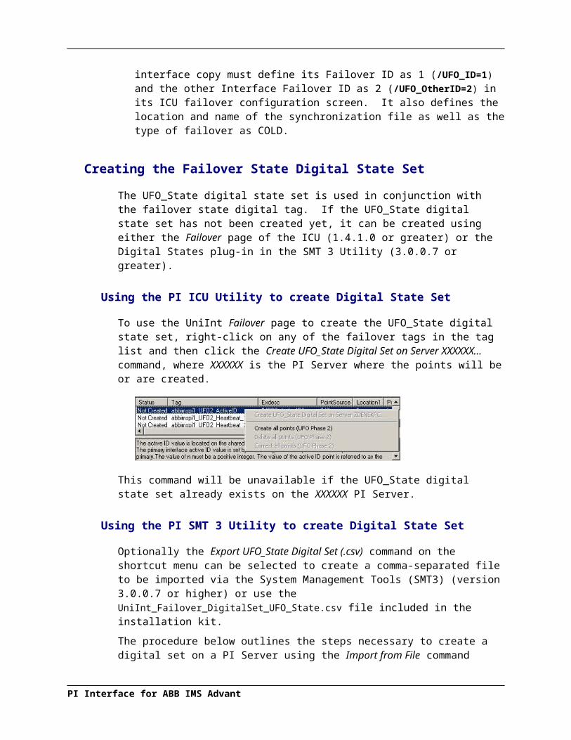
“5 | | 6 IP Addresses DISCONNECTED or with devices IN EXCEPTION” – The interface writes this value when the message associated with a “5 | | ... DISCONNECTED” or “5 | | ... IN EXCEPTION” exceeds 200 bytes. This error message reports only the number of IP addresses that are disconnected or the number of devices that return EXCEPTION response of 4, 10, or 11. You must retrieve detailed error information from the pipc.log.
The interface updates this point whenever the connection status between the interface and the PLC(s) or PLC gateway changes.
[UI_SCINFO]The [UI_SCINFO] Health Point provides scan class information. The value of this point is a string that indicates
the number of scan classes;
the update frequency of the [UI_HEARTBEAT] Health Point; and
the scan class frequencies
An example value for the [UI_SCINFO] Health Point is:3 | 5 | 5 | 60 | 120
The interface updates the value of this point at startup and at each performance summary interval.
[UI_IORATE]The [UI_IORATE] Health Point indicates the sum of
1. the number of scan-based input values the interface collects before it performs exception reporting; and
2. the number of event-based input values the interface collects before it performs exception reporting; and
3. the number of values that the interface writes to output tags that have a SourceTag.
The interface updates this point at the same frequency as the [UI_HEARTBEAT] point. The value of this [UI_IORATE] Health Point may be zero. A stale timestamp for this point indicates that this interface has stopped collecting data.
[UI_MSGCOUNT]The [UI_MSGCOUNT] Health Point tracks the number of messages that the interface has written to the log file since start-up. In general, a large number for this point indicates that the interface is encountering problems. You should investigate the cause of these problems by looking in log messages.
The interface updates the value of this point every 60 seconds. While the interface is running, the value of this point never decreases.
PI Interface for ABB IMS Advant
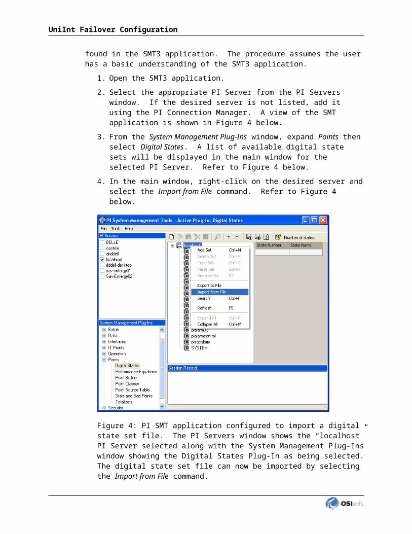
Interface Diagnostics Configuration
[UI_POINTCOUNT]The [UI_POINTCOUNT] Health Point counts number of PI tags loaded by the interface. This count includes all input, output, and triggered input tags. This count does NOT include any Interface Health tags or performance points.
The interface updates the value of this point at startup, on change, and at shutdown.
[UI_OUTPUTRATE]After performing an output to the device, this interface writes the output value to the output tag if the tag has a SourceTag. The [UI_OUTPUTRATE] Health Point tracks the number of these values. If there are no output tags for this interface, it writes the System Digital State No Result to this Health Point.
The interface updates this point at the same frequency as the [UI_HEARTBEAT] point. The interface resets the value of this point to zero at each performance summary interval.
[UI_OUTPUTBVRATE]The [UI_OUTPUTBVRATE] Health Point tracks the number of System Digital State values that the interface writes to output tags that have a SourceTag. If there are no output tags for this interface, it writes the System Digital State No Result to this Health Point.
The interface updates this point at the same frequency as the [UI_HEARTBEAT] point. The interface resets the value of this point to zero at each performance summary interval.
[UI_TRIGGERRATE]The [UI_TRIGGERRATE] Health Point tracks the number of values that the interface writes to event-based input tags. If there are no event-based input tags for this interface, it writes the System Digital State No Result to this Health Point.
The interface updates this point at the same frequency as the [UI_HEARTBEAT] point. The interface resets the value of this point to zero at each performance summary interval.
[UI_TRIGGERBVRATE]The [UI_TRIGGERBVRATE] Health Point tracks the number of System Digital State values that the interface writes to event-based input tags. If there are no event-based input tags for this interface, it writes the System Digital State No Result to this Health Point.
The interface updates this point at the same frequency as the [UI_HEARTBEAT] point. The interface resets the value of this point to zero at each performance summary interval.
[UI_SCIORATE]You can create a [UI_SCIORATE] Health Point for each scan class in this interface. The ICU uses a tag naming convention such that the suffix “.sc1” (for example, sy.st.etamp390.E1.Scan Class IO Rate.sc1) refers to scan class 1, “.sc2” refers to scan class 2, and so on.
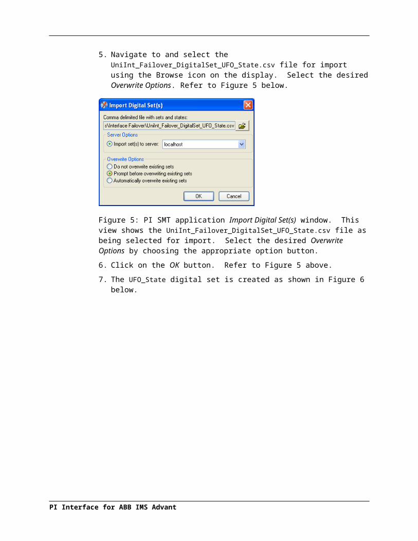
A particular scan class’s [UI_SCIORATE] point indicates the number of values that the interface has collected. If the current value of this point is between zero and the corresponding [UI_SCPOINTCOUNT] point, inclusive, then the interface executed the scan successfully. If a [UI_SCIORATE] point stops updating, then this condition indicates that an error has occurred and the tags for the scan class are no longer receiving new data.
The interface updates the value of a [UI_SCIORATE] point after the completion of the associated scan.
Although the ICU allows you to create the point with the suffix “.sc0”, this point is not applicable to this interface.
[UI_SCBVRATE]You can create a [UI_SCBVRATE] Health Point for each scan class in this interface. The ICU uses a tag naming convention such that the suffix ".sc1" (for example, sy.st.etamp390.E1.Scan Class Bad Value Rate.sc1) refers to scan class 1, ".sc2" refers to scan class 2, and so on.
A particular scan class’s [UI_SCBVRATE] point indicates the number System Digital State values that the interface has collected.
The interface updates the value of a [UI_SCBVRATE] point after the completion of the associated scan.
Although the ICU allows you to create the point with the suffix “.sc0”, this point is not applicable to this interface.
[UI_SCSCANCOUNT]You can create a [UI_SCSCANCOUNT] Health Point for each scan class in this interface. The ICU uses a tag naming convention such that the suffix ".sc1" (for example, sy.st.etamp390.E1.Scan Class Scan Count.sc1) refers to scan class 1, ".sc2" refers to scan class 2, and so on.
A particular scan class's [UI_ SCSCANCOUNT] point tracks the number of scans that the interface has performed.
The interface updates the value of this point at the completion of the associated scan. The interface resets the value to zero at each performance summary interval.
Although there is no "Scan Class 0", the ICU allows you to create the point with the suffix ".sc0". This point indicates the total number of scans the interface has performed for all of its Scan Classes.
[UI_SCSKIPPED]You can create a [UI_SCSKIPPED] Health Point for each scan class in this interface. The ICU uses a tag naming convention such that the suffix ".sc1" (for example, sy.st.etamp390.E1.Scan Class Scans Skipped.sc1) refers to scan class 1, ".sc2" refers to scan class 2, and so on.
A particular scan class’s [UI_SCSKIPPED] point tracks the number of scans that the interface was not able to perform before the scan time elapsed and before the interface performed the next scheduled scan.
PI Interface for ABB IMS Advant

Interface Diagnostics Configuration
The interface updates the value of this point each time it skips a scan. The value represents the total number of skipped scans since the previous performance summary interval. The interface resets the value of this point to zero at each performance summary interval.
Although there is no "Scan Class 0", the ICU allows you to create the point with the suffix ".sc0". This point monitors the total skipped scans for all of the interface’s Scan Classes.
[UI_SCPOINTCOUNT]You can create a [UI_SCPOINTCOUNT] Health Point for each scan class in this interface. The ICU uses a tag naming convention such that the suffix ".sc1" (for example, sy.st.etamp390.E1.Scan Class Point Count.sc1) refers to scan class 1, ".sc2" refers to scan class 2, and so on.
This Health Point monitors the number of tags in a scan class.
The interface updates a [UI_SCPOINTCOUNT] Health Point when it performs the associated scan.
Although the ICU allows you to create the point with the suffix ".sc0", this point is not applicable to this interface.
[UI_SCINSCANTIME]You can create a [UI_SCINSCANTIME] Health Point for each scan class in this interface. The ICU uses a tag naming convention such that the suffix ".sc1" (for example, sy.st.etamp390.E1.Scan Class Scan Time.sc1) refers to scan class 1, ".sc2" refers to scan class 2, and so on.
A particular scan class's [UI_ SCINSCANTIME] point represents the amount of time (in milliseconds) the interface takes to read data from the device, fill in the values for the tags, and send the values to the PI Server.
The interface updates the value of this point at the completion of the associated scan.
[UI_SCINDEVSCANTIME]You can create a [UI_SCINDEVSCANTIME] Health Point for each scan class in this interface. The ICU uses a tag naming convention such that the suffix ".sc1" (for example, sy.st.etamp390.E1.Scan Class Device Scan Time.sc1) refers to scan class 1, ".sc2" refers to scan class 2, and so on.
A particular scan class's [UI_ SCINDEVSCANTIME] point represents the amount of time (in milliseconds) the interface takes to read data from the device and fill in the values for the tags.
The value of a [UI_ SCINDEVSCANTIME] point is a fraction of the corresponding [UI_SCINSCANTIME] point value. You can use these numbers to determine the percentage of time the interface spends communicating with the device compared with the percentage of time communicating with the PI Server.
If the [UI_SCSKIPPED] value is increasing, the [UI_SCINDEVSCANTIME] points along with the [UI_SCINSCANTIME] points can help identify where the delay is occurring: whether the reason is communication with the device, communication with the PI Server, or elsewhere.
The interface updates the value of this point at the completion of the associated scan.

I/O Rate Point
An I/O Rate point measures the rate at which the interface writes data to its input tags. The value of an I/O Rate point represents a 10-minute average of the total number of values per minute that the interface sends to the PI Server.
When the interface starts, it writes 0 to the I/O Rate point. After running for ten minutes, the interface writes the I/O Rate value. The interface continues to write a value every 10 minutes. When the interface stops, it writes 0.
The ICU allows you to create one I/O Rate point for each copy of this interface. Select this interface from the Interface drop-down list, click IO Rate in the parameter category pane, and check Enable IORates for this interface.
As the preceding picture shows, the ICU suggests an Event Counter number and a Tagname for the I/O Rate Point. Click the Save button to save the settings and create the I/O Rate point. Click the Apply button to apply the changes to this copy of the interface.
You need to restart the interface in order for it to write a value to the newly created I/O Rate point. Restart the interface by clicking the Restart button:
(The reason you need to restart the interface is that the PointSource attribute of an I/O Rate point is Lab.)
To confirm that the interface recognizes the I/O Rate Point, look in the pipc.log for a message such as:PI-ModBus 1> IORATE: tag sy.io.etamp390.ModbusE1 configured.
To see the I/O Rate point’s current value (snapshot), click the Refresh snapshot button:
PI Interface for ABB IMS Advant

Interface Diagnostics Configuration
Enable IORates for this InterfaceThe Enable IORates for this interface check box enables or disables I/O Rates for the current interface. To disable I/O Rates for the selected interface, uncheck this box. To enable I/O Rates for the selected interface, check this box.
Event CounterThe Event Counter correlates a tag specified in the iorates.dat file with this copy of the interface. The command-line equivalent is /ec=x, where x is the same number that is assigned to a tag name in the iorates.dat file.
TagnameThe tag name listed in the Tagname box is the name of the I/O Rate tag.
Tag StatusThe Tag Status box indicates whether the I/O Rate tag exists in PI. The possible states are:
Created – This status indicates that the tag exist in PI
Not Created – This status indicates that the tag does not yet exist in PI
Deleted – This status indicates that the tag has just been deleted
Unknown – This status indicates that the PI ICU is not able to access the PI Server
In FileThe In File box indicates whether the I/O Rate tag listed in the tag name and the event counter is in the IORates.dat file. The possible states are:
Yes – This status indicates that the tag name and event counter are in the IORates.dat file
No – This status indicates that the tag name and event counter are not in the IORates.dat file
SnapshotThe Snapshot column holds the snapshot value of the I/O Rate tag, if the I/O Rate tag exists in PI. The Snapshot box is updated when the IORate page is selected, and when the interface is first loaded.
Create/SaveCreate the suggested I/O Rate tag with the tag name indicated in the Tagname box. Or Save any changes for the tag name indicated in the Tagname box.
DeleteDelete the I/O Rate tag listed in the Tagname box.
RenameAllow the user to specify a new name for the I/O Rate tag listed in the Tagname box.
Add to FileAdd the tag to the IORates.dat file with the event counter listed in the Event Counter box.
SearchAllow the user to search the PI Server for a previously defined I/O Rate tag.
Configuring I/O Rate Tags On UNIX
There are two configuration steps.
1. Configuring the PI Point on the PI Server
2. Configuration on the interface node
Configuring PI Point on the PI Server
Create an I/O Rate Tag with the following point attribute values.
Attribute ValuePointSource LAB
PointType float32
Compressing 0
ExcDev 0
PI Interface for ABB IMS Advant

Interface Diagnostics Configuration
Configuration on the Interface Node
For the following examples, assume that the name of the PI tag is abbimsa001, and that the name of the I/O Rate on the home node is abbimsa001.
1. Edit/Create a file called iorates.dat in the $PIHOME/dat directory. PIHOME is an environment variable that is set equal to the PI home directory name as discussed in the PI API manual.
Add a line in the iorates.dat file of the form:abbimsa001, x
where abbimsa001is the name of the I/O Rate Tag and x corresponds to the first instance of the /ec=x parameter in the startup command file. X can be any number between 1 and 34 or between 51 and 200, inclusive. However, it is best to use an event counter, x, that is not equal to 1 because 1 is the default event counter for UniInt-based interfaces.
To specify additional rate counters for additional copies of the interface, create additional I/O Rate tags and additional entries in the iorates.dat file. The event counter, /ec=x, should be unique for each copy of the interface.
2. Set the /ec=x parameter on the startup command file of the interface to match the event counter in the iorates.dat file.
3. The I/O Rate shared memory server and the I/O Rate monitor program must be stopped and started for the changes to take effect. The easiest way to do this is to run the pistop and pistart command scripts with the following commands:sh $PIHOME/bin/pistop
nohup sh $PIHOME/bin/pistart
Determine that the shared memory server and the I/O Rates Monitor are running with the commands:ps –ef | grep ioshmsrv
ps –ef | grep iorates
Interface Status Point
The PI Interface Status Utility (ISU) alerts you when an interface is not currently writing data to the PI Server. This situation commonly occurs if
the monitored interface is running on an interface node, but the interface node cannot communicate with the PI Server; or
the monitored interface is not running, but it failed to write at shutdown a system state such as Intf Shut.
The ISU works by periodically looking at the timestamp of a Watchdog Tag. The Watchdog Tag is a tag whose value a monitored interface (such as this interface) frequently updates. The Watchdog Tag has its ExcDev, ExcMin, and ExcMax point attributes set to 0. So, a non-changing timestamp for the Watchdog Tag indicates that the monitored interface is not writing data.

Please see the Interface Status Utility Interface for complete information on using the ISU. PI Interface Status Utility Interface runs only on a PI Server Node.
If you have used the ICU to configure the PI Interface Status Utility Interface on the PI Server Node, the ICU allows you to create the appropriate ISU point. Select this interface from the Interface drop-down list and click Interface Status in the parameter category pane. Right click on the ISU tag definition window to open the shortcut menu:
Click Create to create the ISU tag.
Use the Tag Search button to select a Watchdog Tag. (Recall that the Watchdog Tag is one of the points for which this interface collects data.)
Select a Scan frequency from the drop-down list box. This Scan frequency is the interval at which the ISU monitors the Watchdog Tag. For optimal performance, choose a Scan frequency that is less frequent than the majority of the scan rates for this interface’s points. For example, if this interface scans most of its points every 30 seconds, choose a Scan frequency of 60 seconds. If this interface scans most of its points every second, choose a Scan frequency of 10 seconds.
If the Tag Status indicates that the ISU tag is Incorrect, right-click to open the shortcut menu and select Correct.
Note: The PI Interface Status Utility Interface – and not this interface – is responsible for updating the ISU tag. So, make sure that the PI Interface Status Utility Interface is running correctly.
PI Interface for ABB IMS Advant

Appendix A. Error and Informational Messages
A string NameID is pre-pended to error messages written to the message log. Name is a non-configurable identifier that is no longer than 9 characters. ID is a configurable identifier that is no longer than 9 characters and is specified using the /id parameter on the startup command-line.
Message Logs
The location of the message log depends upon the platform on which the interface is running. See the UniInt Interface User Manual for more information.
Messages are written to [PIHOME]\dat\pipc.log at the following times.
When the interface starts many informational messages are written to the log. These include the version of the interface, the version of UniInt, the command-line parameters used, and the number of points.
As the interface loads points, messages are sent to the log if there are any problems with the configuration of the points.
If the UniInt /dbUniInt parameter is found in the command-line, then various informational messages are written to the log file.
Messages
System Errors and PI Errors
System errors are associated with positive error numbers. Errors related to PI are associated with negative error numbers.
Error Descriptions on Windows and UNIX On Windows and UNIX, descriptions of system and PI errors can be obtained with the pidiag utility:
Windows: \PI\adm\pidiag /e error_number
UNIX: /PI/adm/pidiag –e error_number
PI Interface for ABB IMS Advant

UniInt Failover Specific Error Messages
Informational
Message 16-May-06 10:38:00abbimspi 1> UniInt failover: Interface in the “Backup” state.
Meaning Upon system startup, the initial transition is made to this state. While in this state, the interface monitors the status of the other interface participating in failover. When configured for Hot failover, data received from the data source is queued and not sent to the PI Server while in this state. The amount of data queued while in this state is determined by the failover update interval. In any case, there will be typically no more than two update intervals of data in the queue at any given time. Some transition chains may cause the queue to hold up to five failover update intervals worth of data.
Message 16-May-06 10:38:05abbimspi 1> UniInt failover: Interface in the “Primary” state and actively sending data to PI. Backup interface not available.
Meaning While in this state, the interface is in its primary role and sends data to the PI Server as it is received. This message also states that there is not a backup interface participating in failover.
Message 16-May-06 16:37:21abbimspi 1> UniInt failover: Interface in the “Primary” state and actively sending data to PI. Backup interface available.
Meaning While in this state, the interface sends data to the PI Server as it is received. This message also states that the other copy of the interface appears to be ready to take over the role of primary.
PI Interface for ABB IMS Advant

Errors (Phase 1 & 2)
Message 16-May-06 17:29:06abbimspi 1> One of the required Failover Synchronization points was not loaded.Error = 0: The Active ID synchronization point was not loaded.The input PI tag was not loaded
Cause The Active ID tag is not configured properly.
Resolution Check validity of point attributes. For example, make sure Location1 attribute is valid for the interface. All failover tags must have the same PointSource and Location1 attributes. Modify point attributes as necessary and restart the interface.
Message 16-May-06 17:38:06abbimspi 1> One of the required Failover Synchronization points was not loaded.Error = 0: The Heartbeat point for this copy of the interface was not loaded.The input PI tag was not loaded
Cause The Heartbeat tag is not configured properly.
Resolution Check validity of point attributes. For example, make sure Location1 attribute is valid for the interface. All failover tags must have the same PointSource and Location1 attributes. Modify point attributes as necessary and restart the interface.
Message 17-May-06 09:06:03abbimspi > The Uniint FailOver ID (/UFO_ID) must be a positive integer.
Cause The UFO_ID parameter has not been assigned a positive integer value.
Resolution Change and verify the parameter to a positive integer and restart the interface.
Message 17-May-06 09:06:03abbimspi 1> The Failover ID parameter (/UFO_ID) was found but the ID for the redundant copy was not found
Cause The /UFO_OtherID parameter is not defined or has not been assigned a positive integer value.
Resolution Change and verify the /UFO_OtherID parameter to a positive integer and restart the interface.
PI Interface for ABB IMS Advant

Error and Informational Messages
Errors (Phase 2)
Unable to open synchronization file
Message 27-Jun-08 17:27:17PI Eight Track 1 1> Error 5: Unable to create file ‘\\georgiaking\GeorgiaKingStorage\UnIntFailover\\PIEightTrack_eight_1.dat’Verify that interface has read/write/create access on file server machine.Initializing UniInt library failedStopping Interface
Cause This message will be seen when the interface is unable to create a new failover synchronization file at startup. The creation of the file only takes place the first time either copy of the interface is started and the file does not exist. The error number most commonly seen is error number 5. Error number 5 is an “access denied” error and is likely the result of a permissions problem.
Resolution Ensure the account the interface is running under has read and write permissions for the folder. The “log on as” property of the Windows service may need to be set to an account that has permissions for the folder.
Error Opening Synchronization File
Message Sun Jun 29 17:18:51 2008PI Eight Track 1 2> WARNING> Failover Warning: Error = 64Unable to open Failover Control File ‘\\georgiaking\GeorgiaKingStorage\Eight\PIEightTrack_eight_1.dat’The interface will not be able to change state if PI is not available
Cause This message will be seen when the interface is unable to open the failover synchronization file. The interface failover will continue to operate correctly as long as communication to the PI Server is not interrupted. If communication to PI is interrupted while one or both interfaces cannot access the synchronization file, the interfaces will remain in the state they were in at the time of the second failure, so the primary interface will remain primary and the backup interface will remain backup.
Resolution Ensure the account the interface is running under has read and write permissions for the folder and file. The “log on as” property of the Windows service may need to be set to an account that has permissions for the folder and file.

Appendix B. PI SDK Options
To access the PI SDK settings for this interface, select this interface from the Interface drop-down list and click UniInt – PI SDK in the parameter category pane.
Disable PI SDKSelect Disable PI SDK to tell the interface not to use the PI SDK. If you want to run the interface in disconnected startup mode, you must choose this option.
The command line equivalent for this option is /pisdk=0.
Use the Interface’s default settingThis selection has no effect on whether the interface uses the PI SDK. However, you must not choose this option if you want to run the interface in disconnected startup mode.
Enable PI SDKSelect Enable PI SDK to tell the interface to use the PI SDK. Choose this option if the PI Server version is earlier than 3.4.370.x or the PI API is earlier than 1.6.0.2, and you want to use extended lengths for the Tag, Descriptor, ExDesc, InstrumentTag, or PointSource point attributes. The maximum lengths for these attributes are:
Attribute Enable the Interface to use the PI SDK
PI Server earlier than 3.4.370.x or PI API earlier than 1.6.0.2, without the use of the PI SDK
Tag 1023 255
Descriptor 1023 26
ExDesc 1023 80
InstrumentTag 1023 32
PointSource 1023 1
However, if you want to run the interface in disconnected startup mode, you must not choose this option.
The command line equivalent for this option is /pisdk=1.
PI Interface for ABB IMS Advant

Appendix C. Hints for PI System Manager
Automatic Interface Start on HP-UX System Startup via ABB’s Process Supervision
It is essential to start PI Interface for ABB Advant processes only after a complete successful startup of the IMS software. Starting a PI Interface for ABB Advant before the ABB processes are up may cause interface termination by signal 6.
ABB provides a way to ensure the right process starting sequence at system startup.
Take the following steps, using the Operator’s Console of the IMS Advant Station:
1. Log in as ocsmgr.
2. Make sure the ABB icon on the bottom of your screen is not dimmed.
3. Click the ABB icon.
4. Choose Settings from the menu.
5. Choose Process Supervision.
6. Fill in the mask that appears on the screen:Program ID ABBIMSPI Startup Order 10000Description ABB IMS Advant Station to PI InterfaceFilePath opt/piapi/abbimspi/bin/StartPIAPIOnBoot <= enter your path here.Button implemented must appear as selected.
7. Click Commit.
8. Click Exit.
9. Click Yes to answer the Alert question.!Do you want to save the changes you have made?
10. Click OK to acknowledge the message.FRM-40400:Transaction complete -- 1 records applied and saved
11. On the File menu select Exit.
12. Log out.
The interface kit contains a template script StartPIAPIOnBoot that starts the PI API (it runs pistart) on system startup.
$PIHOME/bin/pistart calls $PIHOME/bin/sitestart in which you place the interface startup commands (see below).
Put the required definitions of the UNIX environment variables hard coded into StartPIAPIOnBoot. It may then look like this:#!/bin/kshsleep 120
PI Interface for ABB IMS Advant

PIHOME=/opt/piapiSHLIB_PATH=$PIHOME/lib:$SHLIB_PATHABBIMSPI=abbimspiexport PIHOME SHLIB_PATH ABBIMSPInohup sh $PIHOME/bin/pistart
function cleanup { echo “Got signal 15, exiting” $PIHOME/bin/pistop echo “Finished” exit 0}trap cleanup 15
while [ true ]; do sleep 5done
Remember to re-modify this file in the unlikely case that the location of your PI API changes.
Note that the script contains a two-minutes sleep at the beginning that should not be removed. Even if hooked up to ABB Process Supervision, sometimes PI API startup problems after reboot were seen. Those could be remedied by waiting two more minutes after Process Supervision had given the ok to start the application.
Graceful Interface Stop on System Shutdown
Process Supervision also takes care on graceful interface stop when the system shuts down.
The Process Supervision component of the Enterprise Historian software has functions that will both start an application on IMSstart or when the station comes up after a boot as well as to shut it down at IMSstop or when the system is shut down (the HP-UX shutdown command runs the IMSstop script).
Therefore the startup script StartPIAPIOnBoot does not exit. It traps the kill command that will be issued to a supervised process when IMSstop is executed in case of
manual re-start (IMSstop, IMSstart)
automatic re-start
HP-UX reboot or shutdown
When having trapped this kill interrupt the script StartPIAPIOnBoot will then in turn kill the PI API processes that it had started and then exit itself.
PI Interface for ABB IMS Advant

Starting the Interface when the PI API is Started (HP-UX)
To start the PI Interfaces for ABB Advant when the PI API processes start, enter a start-up line for each interface into $PIHOME/bin/sitestart. Example:
sitestart#!/bin/ksh# @(#)sitestart 1.2 09/05/95# File: sitestart## This file is provided to allow site specific applications to be started# whenever the pistart is executed. An appropriate application stop script# should be inserted into the sitestop file.#$PIHOME/$ABBIMSPI/bin/start_demand_interface_1$PIHOME/$ABBIMSPI/bin/start_demand_interface_2
Stopping the Interface When the PI API is Stopped (HP-UX)
Add the following line at the end of the file $PIHOME/bin/sitestop:verify_stopped abbimspi
If you cannot find sitestop in the fashion described below, you may copy it from $PIHOME/build/api or use the lines below to edit your existing file. The complete sitestop script is listed below:############################################################################## @(#)sitestop 1.3 2000/07/25# File: sitestop## This file is provided to allow site specific applications to be stopped# whenever the pistop is executed. An appropriate application start script# should be inserted into the sitestart file or the verify_stopped()# routine below may be used.############################################################################### Bourne shell script to check process shutdown.Verify_stopped(){pid=`ps –e | grep $1 | grep –v grep | awk ‘{ print $1 }’`if [ ${pid:-0} –gt 0 ]then# Change the following line a signal besides SIGTERM is used to stop# the interface. Kill $pid lcount=0 dcount=0 while [ ${pid:-0} –gt 0 ] do if [ ${lcount} –gt 300 ] then break; fi sleep 1 echo ‘.\c’ pid=`ps –e | grep $1 | grep –v grep | awk ‘{ print $1 }’`
PI Interface for ABB IMS Advant

Hints for PI System Manager
lcount=`expr $lcount+1` dcount=`expr $dcount+1` if [ ${dcount} –ge 60 ] then echo $lcount dcount=0 fi done if [ ${dcount} –gt 0 ] then echo ‘ ‘ fi
if [ ${pid:-0} –gt 0 ] then echo “ERROR: Unable to stop $1 (pid = $pid)” $PIHOME/bin/shootq “ERROR: Unable to stop $1 (pid = $pid)” else echo “Program $1 stopped” $PIHOME/bin/shootq “Program $1 stopped” fielse echo “Program $1 not found” $PIHOME/bin/shootq “Program $1 not found”fi}
# EXAMPLE:# verify_stopped buftest
verify_stopped abbimspi
Automatic Interface Start on Windows – Practical Experiences
On HP-UX, ABB Process Supervision can be used to ensure proper application startup. Currently, there is no equivalent tool on Windows.
As with HP-UX, it is very important to start the interface only after the NT ABB processes have completely started. Make sure that the ABB services are set to load as a service. “ABB Advant Process Administration Service” (PAS) should be set to “Automatic” and the “ABB Advant System Message Log “should be set to “Manual”.
The message log will start as dependent of the PAS service.
NOTE: If you set them both to automatic the service will fail to start. After the system has booted and has been up for a few minutes you can see which service you are waiting for by selecting ADVANT in the Start menu. Then select System Services followed by Process Administration. This will open a window with the sub services that ABB must restart. If you open this too soon there will be an error message and you will not see any of the services. The services that should be listed are listed below.
BsSysLogNTcsCleanupcsInitcsNetMaintcsPreMaintcsTransportdxStallsup
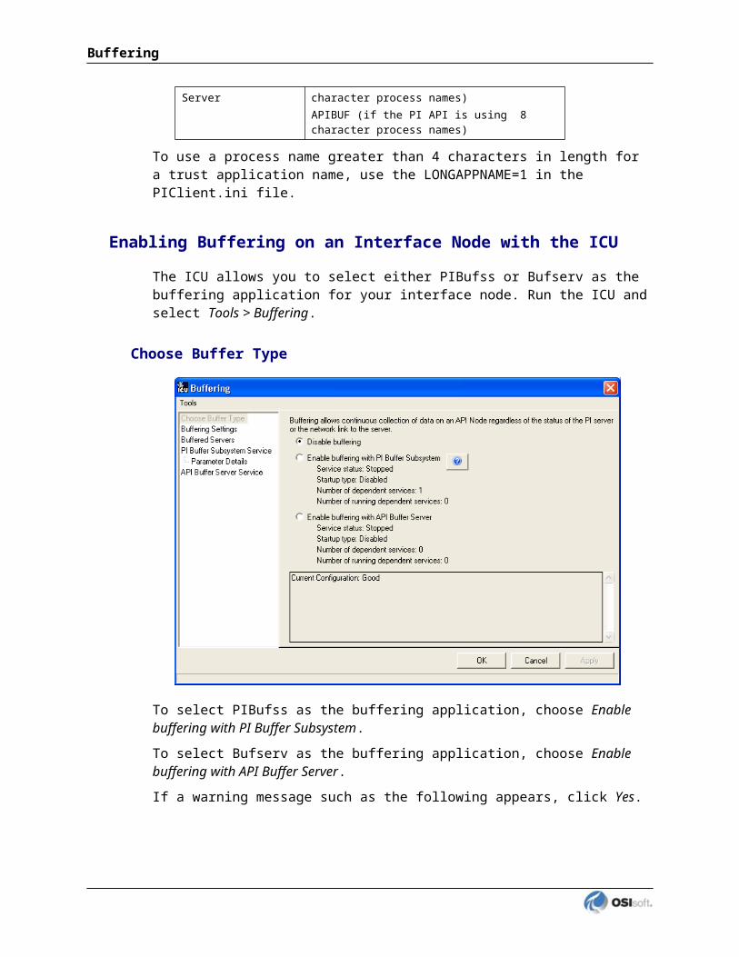
dxTimeSyncdxuprFmsServerLogManagerOmfCleanupOMFCOMOmfNameProcOmfNameProcOmfPMOmfTimerOmoNameBrokerOmoNodeBrokerOmoStorageDomainOmoTypeDirectorySesServer
All these services should be started with the exception of “dxupr”.
It must be ensured that the PI Interface for ABB Advant starts only after a complete startup of all ABB processes. You can configure the wait period via the /startup_delay command line argument. See chapter “Startup Command File” for details.
Practical experience has shown that waiting 5 minutes is long enough to be safe.
Increasing Number of Interfaces per AEH on Windows
On the Windows AEH, you may run into a problem when attempting to have multiple copies of the PI Interface for ABB Advant. The reason is that there is a limit on the number of OMF applications (one of which is the PI Interface for ABB Advant) per AEH. This limit is controlled by the number of semaphores and is stored in the NT registry. If you encounter problems when starting additional copies of the PI Interface for ABB Advant, while the number you had so far ran fine, please contact your local ABB specialist. The following modification may fix the problem. Run regedit and go to the following registry key.
On Advant Enterprise Historian (AEH) 3.0:HKEY_LOCAL_MACHINE\Software\ABB\Advant\SystemModules\OMF\1.5\private\config\Semaphores
On Advant Enterprise Historian (AEH) 3.1:HKEY_LOCAL_MACHINE\SOFTWARE\ABB\SystemServices\OMF\config\Semaphores
Increase the setting of Max (which is at 20 by default). On one site, increasing this to 50, subsequently allowed for 11 OMF processes.
PI Interface for ABB IMS Advant

Appendix D. Interface Control Program – HP-UX only
The interface kit contains a small program named abbimscp. It allows you to change the debug level “on the fly” which can become very useful in problem situations. You can also stop your PI Interface for ABB Advant with this program. There are two files in the kit:abbimscp.makabbimscp.o
Refer to section “Linking the Interface Control Program for instructions about how to ‘make’ abbimscp.
The control program allows you to modify the debug level for the PI Interface for ABB Advant while it is running. If you find it useful or if you have been advised by OSIsoft to do so, run abbimscp to add more run-time information to the interface output file. The syntax is:$abbimscp debuglevel interfacenumber
or$abbimscp q interfacenumber
Starting abbimscp without command line arguments will display the expected usage:$./abbimscpABB IMS Advant Station to PI Interface Control Program Version 1.2
Usage e.g.: ./abbimscp 4 1 - switch debug level to 4 for abbimspi with /in=1Usage e.g.: ./abbimscp q 1 - Shut down interface abbimspi with /in=1$
Note that ‘On Event’ and ‘Cyclic’ interfaces may react a bit slow. Depending on /du=, the interface may stay at bciGetData for a long time or even ‘forever’. The interface’s next chance to check the mailbox for a command issued by abbimscp is when data is received from the DCS and the corresponding callback function is called to send data to PI. For a Cyclic interface, this means that the command you sent will be received by the interface on the next cycle. In an ‘On Event’ interface, the command will be recognized at the next event.
PI Interface for ABB IMS Advant

Appendix E. Achieving Better Interface Performance
Use More Interface Copies
It is better to have more interface copies, each one servicing fewer tags. For example, three interfaces with 500 tags in each have been found to have a better scan performance than one interface with all 1500 tags in it. In fact, the best performance has been seen with one interface copy per scan class.
Use Scan Class Offsets
Better performance and more moderate CPU usage have been seen when scan class offsets are being used. For more details, refer to the description of /f= in section Startup Command File”. Make sure that different scan classes are never called at the same time.
Use a Separate Interface Copy for a Fast Scan Class
If, for some tags, a short scan cycle of three seconds, for example, is wanted, while the majority of tags is scanned every 30, 40, 50 or 60 seconds, it is more efficient to have the three-second tags serviced by a separate interface instance.
Consider the Transfer Method “On Event” (ABB Master only)
The interface, via ABB’s AdvaInform UserAPI provides the possibility to read object attributes “On Event”. For some attributes with a discrete characteristic, it makes more sense to have the DCS tell the interface when the attribute value has changed rather than to scan this object periodically. Given that the system is not overloaded with events, an event interface can hardly be seen in the UNIX process list, hence leaving more resources for the “On Demand” interfaces. However, setting up a permanent subscription on the event of a very noisy signal can result in tremendous CPU load, and hence in the opposite of what was intended.
See section Introduction for more details about the “On Event” method. The ‘On Event’ method is not recommended for MOD 300.
PI Interface for ABB IMS Advant

Appendix F. Test Environment
IMS 2.0
ABB Master
Advant Controller AC 450MasterBus MB 300eAdvant Station 530 IMS, 288 Mbyte RAMRTA card 16 MbyteIMS 2.0 with “programming option” (including AdvaInform UserAPI 1.3) HP-UX 10.20
Intel Pentium 200 MHz, 192 MB RAM, 2Gbyte diskPI 3.1 Build 2.71 (in a late phase also PI 3.2 Build 3.29)Intel NT 4.0 Service Pack 3ABB IMS Advant Station to PI interface version 3.11300 AI objects + 100 DI objects on the ABB Master Test system were mapped to 7000 different PI tags
AEH 2.1
ABB MOD 300
This is AdvaInform Enterprise Historian Version 2.1-0.Software versions included in the AdvaInform Basic Functions 2.2-0:- HP-UX 10.20- Motif 1.2- X X11R5- Oracle 7.3.2.3- TeleUSE 3.2-1- OS 1.8-0- OMF 1.4-5- TypeDir 5.1-1- UXBase 2.3-0
- PI API HP-UX 1.3.4- PI 3.2 Build 357.17 on Intel NT 4
PI Interface for ABB IMS Advant
AEH 2.2
ABB Master
Information about version
This is AdvaInform Enterprise Historian Version 2.2-0.
Software versions included in the AdvaInform Basic Functions 2.2-0:
- HP-UX 10.20- Motif 1.2- X X11R5- Oracle 7.3.2- TeleUSE 3.02.B- OS 1.8-0- OMF 1.4-5- TypeDir 5.1-3- UXBase 2.3-0
- PI API HP-UX 1.3.6 (cfront compatible option 1.3.4 chosen)- PI Server PI 3.3, Build 361.96 on Windows 2000- Interface version 5.09
PI Interface for ABB IMS Advant

Appendix G. Attribute Lists via getObj
The following lists are summaries of attributes, events and operations for the six Basic Object Types + one example for a CCF_PID_LOOP object. Similar information can be retrieved for any other object type. Remember that you have to change to folder /opt/advant/UserAPI/examples first.$ cd /opt/advant/UserAPI/examples$ getObj AI================================================================= Object AI is of type AI which has:
-Attributes------------------------------------------------------ 0 NAME STRING 21 byte 1 DESCRIPTION STRING 29 byte 2 STATUS BITSET 4 byte 3 UNIT STRING 7 byte 4 RANGE_MIN FLOAT 4 byte 5 RANGE_MAX FLOAT 4 byte 6 VALUE FLOAT 4 byte 7 ERROR_TREAT SHORT 2 byte 8 NO_OF_DEC SMALL 1 byte 9 SUBSYSTEM SMALL 1 byte10 CLASS SMALL 1 byte11 HI_LIM2 FLOAT 4 byte12 HI_LIM1 FLOAT 4 byte13 LO_LIM1 FLOAT 4 byte14 LO_LIM2 FLOAT 4 byte15 USE_HI_LIM2 BOOLEAN 1 byte16 USE_HI_LIM1 BOOLEAN 1 byte17 USE_LO_LIM1 BOOLEAN 1 byte18 USE_LO_LIM2 BOOLEAN 1 byte19 LIM1_TREAT SHORT 2 byte20 LIM2_TREAT SHORT 2 byte21 ain_ab1_dcx COMPOSITE 12 byte22 ain_ab2_dcx COMPOSITE 80 byte23 ain_ab3_dcx COMPOSITE 96 byte24 ain_ab4_dcx COMPOSITE 100 byte
-Operations------------------------------------------------------ 0 Delete OPERATION 0 byte 1 Deactivate OPERATION 0 byte 2 Copy OPERATION 21 byte 3 NormalOperation OPERATION 0 byte 4 SELECT OPERATION 84 byte 5 DESELECT OPERATION 16 byte 6 ORDER OPERATION 24 byte 7 ACKNOWLEDGE OPERATION 16 byte 8 GETVALUE OPERATION 28 byte
-Events---------------------------------------------------------- 0 EVENT EVENT 0 byte$ getObj AO================================================================= Object AO is of type AO which has:
PI Interface for ABB IMS Advant

-Attributes------------------------------------------------------ 0 NAME STRING 21 byte 1 DESCRIPTION STRING 29 byte 2 STATUS BITSET 4 byte 3 UNIT STRING 7 byte 4 RANGE_MIN FLOAT 4 byte 5 RANGE_MAX FLOAT 4 byte 6 VALUE FLOAT 4 byte 7 MAX_LIM FLOAT 4 byte 8 MIN_LIM FLOAT 4 byte 9 START_VALUE SHORT 2 byte10 ERROR_TREAT SHORT 2 byte11 NO_OF_DEC SMALL 1 byte12 SUBSYSTEM SMALL 1 byte13 CLASS SMALL 1 byte14 aout_ab1_dcx COMPOSITE 12 byte15 aout_ab2_dcx COMPOSITE 80 byte16 aout_ab3_dcx COMPOSITE 88 byte
-Operations------------------------------------------------------ 0 Delete OPERATION 0 byte 1 Deactivate OPERATION 0 byte 2 Copy OPERATION 21 byte 3 NormalOperation OPERATION 0 byte 4 SELECT OPERATION 84 byte 5 DESELECT OPERATION 16 byte 6 ORDER OPERATION 24 byte 7 ACKNOWLEDGE OPERATION 16 byte 8 GETVALUE OPERATION 28 byte
-Events---------------------------------------------------------- 0 EVENT EVENT 0 byte=================================================================$ getObj DI================================================================= Object DI is of type DI which has:
-Attributes------------------------------------------------------ 0 NAME STRING 21 byte 1 DESCRIPTION STRING 29 byte 2 STATUS BITSET 4 byte 3 ERROR_TREAT SHORT 2 byte 4 VALUE_TREAT SHORT 2 byte 5 SUBSYSTEM SMALL 1 byte 6 CLASS SMALL 1 byte 7 din_ab1_dcx COMPOSITE 4 byte 8 din_ab2_dcx COMPOSITE 60 byte
-Operations------------------------------------------------------ 0 Delete OPERATION 0 byte 1 Deactivate OPERATION 0 byte 2 Copy OPERATION 21 byte 3 NormalOperation OPERATION 0 byte 4 SELECT OPERATION 84 byte 5 DESELECT OPERATION 16 byte 6 ORDER OPERATION 24 byte 7 ACKNOWLEDGE OPERATION 16 byte 8 GETVALUE OPERATION 28 byte
-Events---------------------------------------------------------- 0 EVENT EVENT 0 byte=================================================================
$ getObj DO
PI Interface for ABB IMS Advant

================================================================= Object DO is of type DO which has:-Attributes------------------------------------------------------ 0 NAME STRING 21 byte 1 DESCRIPTION STRING 29 byte 2 STATUS BITSET 4 byte 3 ERROR_TREAT SHORT 2 byte 4 SUBSYSTEM SMALL 1 byte 5 CLASS SMALL 1 byte 6 dout_ab1_dcx COMPOSITE 4 byte 7 dout_ab2_dcx COMPOSITE 56 byte
-Operations------------------------------------------------------ 0 Delete OPERATION 0 byte 1 Deactivate OPERATION 0 byte 2 Copy OPERATION 21 byte 3 NormalOperation OPERATION 0 byte 4 SELECT OPERATION 84 byte 5 DESELECT OPERATION 16 byte 6 ORDER OPERATION 24 byte 7 ACKNOWLEDGE OPERATION 16 byte 8 GETVALUE OPERATION 28 byte
-Events---------------------------------------------------------- 0 EVENT EVENT 0 byte
$ getObj DAT================================================================= Object DAT is of type DAT which has:
-Attributes------------------------------------------------------ 0 NAME STRING 21 byte 1 VALID SMALL 1 byte 2 VAL_TYPE SMALL 1 byte 3 B0_VAL BOOLEAN 1 byte 4 B1_VAL BOOLEAN 1 byte 5 B2_VAL BOOLEAN 1 byte 6 B3_VAL BOOLEAN 1 byte 7 B4_VAL BOOLEAN 1 byte 8 B5_VAL BOOLEAN 1 byte 9 B6_VAL BOOLEAN 1 byte10 B7_VAL BOOLEAN 1 byte11 B8_VAL BOOLEAN 1 byte12 B9_VAL BOOLEAN 1 byte13 B10_VAL BOOLEAN 1 byte14 B11_VAL BOOLEAN 1 byte15 B12_VAL BOOLEAN 1 byte16 B13_VAL BOOLEAN 1 byte17 B14_VAL BOOLEAN 1 byte18 B15_VAL BOOLEAN 1 byte19 B16_VAL BOOLEAN 1 byte20 B17_VAL BOOLEAN 1 byte21 B18_VAL BOOLEAN 1 byte22 B19_VAL BOOLEAN 1 byte23 B20_VAL BOOLEAN 1 byte24 B21_VAL BOOLEAN 1 byte25 B22_VAL BOOLEAN 1 byte26 B23_VAL BOOLEAN 1 byte27 B24_VAL BOOLEAN 1 byte28 B25_VAL BOOLEAN 1 byte29 B26_VAL BOOLEAN 1 byte30 B27_VAL BOOLEAN 1 byte31 B28_VAL BOOLEAN 1 byte32 B29_VAL BOOLEAN 1 byte
PI Interface for ABB IMS Advant

Attribute Lists via getObj
33 B30_VAL BOOLEAN 1 byte34 B31_VAL BOOLEAN 1 byte35 IW_VAL SHORT 2 byte36 IL_VAL LONG 4 byte37 R_VAL FLOAT 4 byte38 dat_ab1_dcx COMPOSITE 8 byte39 dat_ab2_dcx COMPOSITE 28 byte
-Operations------------------------------------------------------ 0 Delete OPERATION 0 byte 1 Deactivate OPERATION 0 byte 2 Copy OPERATION 21 byte 3 NormalOperation OPERATION 0 byte 4 DAT_SELECT OPERATION 52 byte 5 DAT_DESELECT OPERATION 16 byte 6 DAT_ORDER OPERATION 32 byte
-Events---------------------------------------------------------- 0 EVENT EVENT 0 byte =================================================================$ getObj TEXT ================================================================= Object TEXT is of type TEXT which has:
-Attributes------------------------------------------------------ 0 NAME STRING 21 byte 1 INT_LONG LONG 4 byte 2 TEXT_REAL FLOAT 4 byte 3 DISPMAX FLOAT 4 byte 4 DISPMIN FLOAT 4 byte 5 NO_OF_DEC SMALL 1 byte 6 ORD_BLK SMALL 1 byte 7 STATUS SH_BITSET 2 byte 8 TEXT STRING 73 byte 9 td_ab1_dcx COMPOSITE 88 byte 10 td_ab2_dcx COMPOSITE 120 byte
-Operations------------------------------------------------------ 0 Delete OPERATION 0 byte 1 Deactivate OPERATION 0 byte 2 Copy OPERATION 21 byte 3 NormalOperation OPERATION 0 byte 4 TEXT_SELECT OPERATION 84 byte 5 TEXT_DESELECT OPERATION 16 byte 6 TEXT_ORDER OPERATION 104 byte
-Events---------------------------------------------------------- 0 EVENT EVENT 0 byte =================================================================$
$ getObj CCF_PID_LOOP Object CCF_PID_LOOP is of type CCF_PID_LOOP which has:
-Attributes------------------------------------------------------- 0 NAME STRING 21 byte 1 APL_F1 USMALL 1 byte 2 APL_F10 USMALL 1 byte 3 APL_F2 USMALL 1 byte 4 APL_F3 USMALL 1 byte 5 APL_F4 USMALL 1 byte 6 APL_F5 USMALL 1 byte 7 APL_F6 USMALL 1 byte 8 APL_F7 USMALL 1 byte

9 APL_F8 USMALL 1 byte 10 APL_F9 USMALL 1 byte 11 BLKBYTE SHORT 2 byte 12 CHK_ENB USMALL 1 byte 13 COMP_ALL USMALL 1 byte 14 COMP_MOD USMALL 1 byte 15 COMP_REQ USMALL 1 byte 16 CONTPR LONG 4 byte 17 CONTUAC USMALL 1 byte 18 CONT_SRC LONG 4 byte 19 CO_ENAB USMALL 1 byte 20 CO_RLREF LONG 4 byte 21 CO_STATE USMALL 1 byte 22 DEMAND_M USMALL 1 byte 23 DEMAND_N USMALL 1 byte 24 DEMAND_X ARRAY 20 byte 25 DEPENAB USMALL 1 byte 26 DEVLPNUM ULONG 4 byte 27 DMD_SCAN USMALL 1 byte 28 ENAB_FLG USMALL 1 byte 29 INDEX_1 USMALL 1 byte 30 INDEX_10 USMALL 1 byte 31 INDEX_2 USMALL 1 byte 32 INDEX_3 USMALL 1 byte 33 INDEX_4 USMALL 1 byte 34 INDEX_5 USMALL 1 byte 35 INDEX_6 USMALL 1 byte 36 INDEX_7 USMALL 1 byte 37 INDEX_8 USMALL 1 byte 38 INDEX_9 USMALL 1 byte 39 INSTR SHORT 2 byte 40 INSTRTYP USMALL 1 byte 41 LER_ACTN USMALL 1 byte 42 LOOPDESC STRING 25 byte 43 LOOPLREF LONG 4 byte 44 LOOPTYPE USMALL 1 byte 45 LOOP_DAT LONG 4 byte 46 LOOP_SEQ FLOAT 4 byte 47 LP_CONFG SMALL 1 byte 48 LP_STATE USMALL 1 byte 49 NORMSTAT USMALL 1 byte 50 OUTERROR USMALL 1 byte 51 PHASE USMALL 1 byte 52 POSTENAB USMALL 1 byte 53 PREV_STA USMALL 1 byte 54 REM_INP USMALL 1 byte 55 SCANFLAG USMALL 1 byte 56 SCANRATE USHORT 2 byte 57 TAG STRING 13 byte 58 TCL_DONE USMALL 1 byte 59 UNITNUM USHORT 2 byte 60 DQ_ENAB USMALL 1 byte 61 ALG_NUM SMALL 1 byte 62 ALM_COMP BITSET 4 byte 63 ALM_MASK LONG 4 byte 64 CONINDEX USMALL 1 byte 65 CON_DQ USMALL 1 byte 66 CON_DVDQ USMALL 1 byte 67 CON_DVHI USMALL 1 byte 68 CON_DVLO USMALL 1 byte 69 CON_HI USMALL 1 byte 70 CON_HIHI USMALL 1 byte 71 CON_IROC USMALL 1 byte 72 CON_LO USMALL 1 byte
PI Interface for ABB IMS Advant
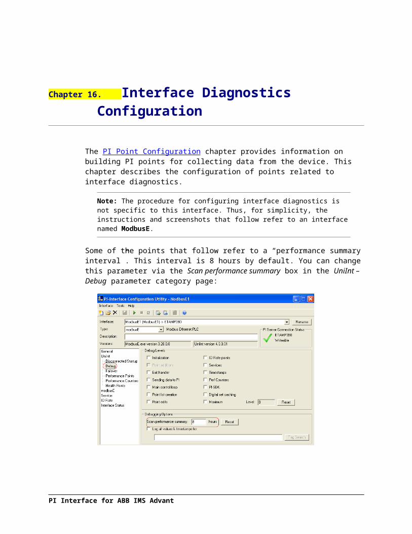
Attribute Lists via getObj
73 CON_LOLO USMALL 1 byte 74 CON_ODQ USMALL 1 byte 75 CON_OHI USMALL 1 byte 76 CON_OIRC USMALL 1 byte 77 CON_OLO USMALL 1 byte 78 CON_SPDQ USMALL 1 byte 79 CON_SPHI USMALL 1 byte 80 CON_SPLO USMALL 1 byte 81 DECPTPOS USMALL 1 byte 82 DEV_ALM USMALL 1 byte 83 DEV_DQ_B USMALL 1 byte 84 DEV_HI USMALL 1 byte 85 DEV_LO USMALL 1 byte 86 C_DQ_BAD USMALL 1 byte 87 DQ_MEAS USMALL 1 byte 88 ENGUNITS STRING 7 byte 89 ERR_FCM USMALL 1 byte 90 EU_DEBD FLOAT 4 byte 91 FCMS ARRAY 64 byte 92 HI USMALL 1 byte 93 HIHI USMALL 1 byte 94 HIHILIMT FLOAT 4 byte 95 HILIMT FLOAT 4 byte 96 HI_CONV FLOAT 4 byte 97 IROCLIMT FLOAT 4 byte 98 IROC_HI USMALL 1 byte 99 LOLIMT FLOAT 4 byte100 LOLO USMALL 1 byte101 LOLOLIMT FLOAT 4 byte102 LOW USMALL 1 byte103 LO_CONV FLOAT 4 byte104 MEASLREF USMALL 1 byte105 MEASURE FLOAT 4 byte106 MEAS_ALM USMALL 1 byte107 MROC_ALM USMALL 1 byte108 NBKINPTS SMALL 1 byte109 OROC_ALM USMALL 1 byte110 OUTP_ALM USMALL 1 byte111 OUT_DQ_B USMALL 1 byte112 OUT_HI USMALL 1 byte113 OUT_IRC USMALL 1 byte114 OUT_LO USMALL 1 byte115 RD1_K1 FLOAT 4 byte116 SPT_ALM USMALL 1 byte117 SP_DQ USMALL 1 byte118 SP_HI USMALL 1 byte119 SP_LO USMALL 1 byte120 TRNDLREF LONG 4 byte121 TRNDRATE USHORT 2 byte122 MEASURE_COMP COMPOSITE 12 byte123 BAD_INP SMALL 1 byte124 BALANCE SMALL 1 byte125 B_DQ USMALL 1 byte126 B_HILI FLOAT 4 byte127 B_LMAL USMALL 1 byte128 B_LOLI FLOAT 4 byte129 B_MDAL USMALL 1 byte130 B_MODE USMALL 1 byte131 B_REMIN LONG 4 byte132 B_VALUE FLOAT 4 byte133 CTL_RATE SMALL 1 byte134 DATAQUAL USHORT 2 byte135 FCM_MODE USMALL 1 byte136 FULL_OUT FLOAT 4 byte

137 INITMODE USMALL 1 byte138 INIT_FLG USMALL 1 byte139 INIT_OUT FLOAT 4 byte140 INPUT_1 LONG 4 byte141 LINKFAIL USMALL 1 byte142 OUMDFAIL USMALL 1 byte143 OUTRETMD USMALL 1 byte144 OUTRFAIL FLOAT 4 byte145 OUT_COND USMALL 1 byte146 OUT_DEBD FLOAT 4 byte147 OUT_HILI FLOAT 4 byte148 OUT_LOLI FLOAT 4 byte149 OUT_MODE SMALL 1 byte150 OUVAFAIL USMALL 1 byte151 OU_LM_AL SMALL 1 byte152 OU_MD_AL SMALL 1 byte153 PREVOUMD SMALL 1 byte154 RATE_CNT LONG 4 byte155 RATE_LIM FLOAT 4 byte156 REMTRKFL LONG 4 byte157 REMTRKIN LONG 4 byte158 REM_CRTL USMALL 1 byte159 RESULT FLOAT 4 byte160 RET_OUMD SMALL 1 byte161 R_DQ USMALL 1 byte162 R_HILI FLOAT 4 byte163 R_LMAL USMALL 1 byte164 R_LOLI FLOAT 4 byte165 R_MDAL USMALL 1 byte166 R_MODE USMALL 1 byte167 R_REMIN LONG 4 byte168 R_VALUE FLOAT 4 byte169 TRAK_DQ USMALL 1 byte170 TRAK_VAR FLOAT 4 byte171 TRKFLPAD LONG 4 byte172 TRKINPAD LONG 4 byte173 TRKORET USMALL 1 byte174 TRK_FLAG USMALL 1 byte175 TRK_STAT USMALL 1 byte176 WD_COUNT LONG 4 byte177 WD_TIME LONG 4 byte178 WORST_DQ USMALL 1 byte179 OUTPUT_COMP COMPOSITE 8 byte180 ACCUMINT DOUBLE 8 byte181 ACTION USMALL 1 byte182 AC_GAIN FLOAT 4 byte183 AC_RESET FLOAT 4 byte184 ADPTMODE SMALL 1 byte185 A_GAIN LONG 4 byte186 A_RESET LONG 4 byte187 BAD_SPT SMALL 1 byte188 BS_GAIN FLOAT 4 byte189 BS_RESET FLOAT 4 byte190 C FLOAT 4 byte191 CASCADE USMALL 1 byte192 DELTA_T FLOAT 4 byte193 DEV_DEBD FLOAT 4 byte194 DEV_HILI FLOAT 4 byte195 DEV_LOLI FLOAT 4 byte196 DEV_VAL FLOAT 4 byte197 DTC_ENAB USMALL 1 byte198 END_SPT FLOAT 4 byte199 ERROR FLOAT 4 byte200 ERR_SQR USMALL 1 byte
PI Interface for ABB IMS Advant

Attribute Lists via getObj
201 EXFBENAB USMALL 1 byte202 FFFBMODE SMALL 1 byte203 FF_CONST FLOAT 4 byte204 FF_TYPE USMALL 1 byte205 FILT_CON FLOAT 4 byte206 GAIN_DQ USMALL 1 byte207 GAIN_LIM FLOAT 4 byte208 INC_CV FLOAT 4 byte209 INC_FLAG USMALL 1 byte210 INC_H_DB FLOAT 4 byte211 INC_L_DB FLOAT 4 byte212 INC_MFLG USMALL 1 byte213 INITSPMD USMALL 1 byte214 INIT_SPT FLOAT 4 byte215 INTGTYPE SMALL 1 byte216 INT_DER FLOAT 4 byte217 INT_FORM USMALL 1 byte218 MPROCVAL FLOAT 4 byte219 M_R_HILI FLOAT 4 byte220 M_R_LOLI FLOAT 4 byte221 M_R_TYPE SMALL 1 byte222 M_R_VAL FLOAT 4 byte223 PREACT SMALL 1 byte224 PREACTIM FLOAT 4 byte225 PRERMPMD SMALL 1 byte226 PREVFFFB SMALL 1 byte227 PREVINTG FLOAT 4 byte228 PREVSPMD SMALL 1 byte229 PROC_DQ USMALL 1 byte230 PROC_ENG FLOAT 4 byte231 PROC_HV FLOAT 4 byte232 PROC_LV FLOAT 4 byte233 PROC_VAL FLOAT 4 byte234 PROPTYPE SMALL 1 byte235 RD1_K2 FLOAT 4 byte236 RD1_K3 FLOAT 4 byte237 RD1_K4 FLOAT 4 byte238 REMINF SMALL 1 byte239 REMSETPT LONG 4 byte240 REMSPTN SMALL 1 byte241 REM_DTC LONG 4 byte242 REM_EXFB LONG 4 byte243 REM_EXFF LONG 4 byte244 RESET_DQ USMALL 1 byte245 RET_SPMD SMALL 1 byte246 RMP_RATE FLOAT 4 byte247 SETPOINT FLOAT 4 byte248 SETPTN FLOAT 4 byte249 SETPT_DQ USMALL 1 byte250 SPMDFAIL USMALL 1 byte251 SPREFAIL FLOAT 4 byte252 SPRETMD USMALL 1 byte253 SPTRKSRC LONG 4 byte254 SPT_HILI FLOAT 4 byte255 SPT_LOLI FLOAT 4 byte256 SPT_MODE SMALL 1 byte257 SPVAFAIL USMALL 1 byte258 SP_LM_AL SMALL 1 byte259 SP_MD_AL SMALL 1 byte260 TRKSRET USMALL 1 byte261 TUNE_FLG USMALL 1 byte262 ATUNE_ID ULONG 4 byte263 EXEC_AT USMALL 1 byte264 SETPOINT_COMP COMPOSITE 8 byte

-Operations------------------------------------------------------- 0 Delete OPERATION 0 byte 1 Deactivate OPERATION 0 byte 2 Copy OPERATION 21 byte 3 NormalOperation OPERATION 0 byte 4 TAKE_CONTROL OPERATION 4 byte 5 PUT_APL_F1 OPERATION 1 byte 6 PUT_APL_F10 OPERATION 1 byte 7 PUT_APL_F2 OPERATION 1 byte 8 PUT_APL_F3 OPERATION 1 byte 9 PUT_APL_F4 OPERATION 1 byte 10 PUT_APL_F5 OPERATION 1 byte 11 PUT_APL_F6 OPERATION 1 byte 12 PUT_APL_F7 OPERATION 1 byte 13 PUT_APL_F8 OPERATION 1 byte 14 PUT_APL_F9 OPERATION 1 byte 15 PUT_BLKBYTE OPERATION 2 byte 16 PUT_CHK_ENB OPERATION 1 byte 17 PUT_COMP_ALL OPERATION 1 byte 18 PUT_COMP_MOD OPERATION 1 byte 19 PUT_COMP_REQ OPERATION 1 byte 20 PUT_CONTPR OPERATION 4 byte 21 PUT_CONTUAC OPERATION 1 byte 22 PUT_CONT_SRC OPERATION 4 byte 23 PUT_CO_ENAB OPERATION 1 byte 24 PUT_CO_RLREF OPERATION 4 byte 25 PUT_CO_STATE OPERATION 1 byte 26 PUT_DEMAND_M OPERATION 1 byte 27 PUT_DEMAND_N OPERATION 1 byte 28 PUT_DEMAND_X OPERATION 20 byte 29 PUT_DEPENAB OPERATION 1 byte 30 PUT_DEVLPNUM OPERATION 4 byte 31 PUT_DMD_SCAN OPERATION 1 byte 32 PUT_ENAB_FLG OPERATION 1 byte 33 PUT_INDEX_1 OPERATION 1 byte 34 PUT_INDEX_10 OPERATION 1 byte 35 PUT_INDEX_2 OPERATION 1 byte 36 PUT_INDEX_3 OPERATION 1 byte 37 PUT_INDEX_4 OPERATION 1 byte 38 PUT_INDEX_5 OPERATION 1 byte 39 PUT_INDEX_6 OPERATION 1 byte 40 PUT_INDEX_7 OPERATION 1 byte 41 PUT_INDEX_8 OPERATION 1 byte 42 PUT_INDEX_9 OPERATION 1 byte 43 PUT_INSTR OPERATION 2 byte 44 PUT_INSTRTYP OPERATION 1 byte 45 PUT_LER_ACTN OPERATION 1 byte 46 PUT_LOOPDESC OPERATION 25 byte 47 PUT_LOOPLREF OPERATION 4 byte 48 PUT_LOOPTYPE OPERATION 1 byte 49 PUT_LOOP_DAT OPERATION 4 byte 50 PUT_LOOP_SEQ OPERATION 4 byte 51 PUT_LP_CONFG OPERATION 1 byte 52 PUT_LP_STATE OPERATION 1 byte 53 PUT_NORMSTAT OPERATION 1 byte 54 PUT_OUTERROR OPERATION 1 byte 55 PUT_PHASE OPERATION 1 byte 56 PUT_POSTENAB OPERATION 1 byte 57 PUT_PREV_STA OPERATION 1 byte 58 PUT_REM_INP OPERATION 1 byte 59 PUT_SCANFLAG OPERATION 1 byte 60 PUT_SCANRATE OPERATION 2 byte 61 PUT_TAG OPERATION 13 byte
PI Interface for ABB IMS Advant

Attribute Lists via getObj
62 PUT_TCL_DONE OPERATION 1 byte 63 PUT_UNITNUM OPERATION 2 byte 64 PUT_DQ_ENAB OPERATION 1 byte 65 PUT_ALG_NUM OPERATION 1 byte 66 PUT_ALM_COMP OPERATION 4 byte 67 PUT_ALM_MASK OPERATION 4 byte 68 PUT_CONINDEX OPERATION 1 byte 69 PUT_CON_DQ OPERATION 1 byte 70 PUT_CON_DVDQ OPERATION 1 byte 71 PUT_CON_DVHI OPERATION 1 byte 72 PUT_CON_DVLO OPERATION 1 byte 73 PUT_CON_HI OPERATION 1 byte 74 PUT_CON_HIHI OPERATION 1 byte 75 PUT_CON_IROC OPERATION 1 byte 76 PUT_CON_LO OPERATION 1 byte 77 PUT_CON_LOLO OPERATION 1 byte 78 PUT_CON_ODQ OPERATION 1 byte 79 PUT_CON_OHI OPERATION 1 byte 80 PUT_CON_OIRC OPERATION 1 byte 81 PUT_CON_OLO OPERATION 1 byte 82 PUT_CON_SPDQ OPERATION 1 byte 83 PUT_CON_SPHI OPERATION 1 byte 84 PUT_CON_SPLO OPERATION 1 byte 85 PUT_DECPTPOS OPERATION 1 byte 86 PUT_DEV_ALM OPERATION 1 byte 87 PUT_DEV_DQ_B OPERATION 1 byte 88 PUT_DEV_HI OPERATION 1 byte 89 PUT_DEV_LO OPERATION 1 byte 90 PUT_C_DQ_BAD OPERATION 1 byte 91 PUT_DQ_MEAS OPERATION 1 byte 92 PUT_ENGUNITS OPERATION 7 byte 93 PUT_ERR_FCM OPERATION 1 byte 94 PUT_EU_DEBD OPERATION 4 byte 95 PUT_FCMS OPERATION 64 byte 96 PUT_HI OPERATION 1 byte 97 PUT_HIHI OPERATION 1 byte 98 PUT_HIHILIMT OPERATION 4 byte 99 PUT_HILIMT OPERATION 4 byte100 PUT_HI_CONV OPERATION 4 byte101 PUT_IROCLIMT OPERATION 4 byte102 PUT_IROC_HI OPERATION 1 byte103 PUT_LOLIMT OPERATION 4 byte104 PUT_LOLO OPERATION 1 byte105 PUT_LOLOLIMT OPERATION 4 byte106 PUT_LOW OPERATION 1 byte107 PUT_LO_CONV OPERATION 4 byte108 PUT_MEASLREF OPERATION 1 byte109 PUT_MEASURE OPERATION 4 byte110 PUT_MEAS_ALM OPERATION 1 byte111 PUT_MROC_ALM OPERATION 1 byte112 PUT_NBKINPTS OPERATION 1 byte113 PUT_OROC_ALM OPERATION 1 byte114 PUT_OUTP_ALM OPERATION 1 byte115 PUT_OUT_DQ_B OPERATION 1 byte116 PUT_OUT_HI OPERATION 1 byte117 PUT_OUT_IRC OPERATION 1 byte118 PUT_OUT_LO OPERATION 1 byte119 PUT_RD1_K1 OPERATION 4 byte120 PUT_SPT_ALM OPERATION 1 byte121 PUT_SP_DQ OPERATION 1 byte122 PUT_SP_HI OPERATION 1 byte123 PUT_SP_LO OPERATION 1 byte124 PUT_TRNDLREF OPERATION 4 byte125 PUT_TRNDRATE OPERATION 2 byte

126 PUT_BAD_INP OPERATION 1 byte127 PUT_BALANCE OPERATION 1 byte128 PUT_B_DQ OPERATION 1 byte129 PUT_B_HILI OPERATION 4 byte130 PUT_B_LMAL OPERATION 1 byte131 PUT_B_LOLI OPERATION 4 byte132 PUT_B_MDAL OPERATION 1 byte133 PUT_B_MODE OPERATION 1 byte134 PUT_B_REMIN OPERATION 4 byte135 PUT_B_VALUE OPERATION 4 byte136 PUT_CTL_RATE OPERATION 1 byte137 PUT_DATAQUAL OPERATION 2 byte138 PUT_FCM_MODE OPERATION 1 byte139 PUT_FULL_OUT OPERATION 4 byte140 PUT_INITMODE OPERATION 1 byte141 PUT_INIT_FLG OPERATION 1 byte142 PUT_INIT_OUT OPERATION 4 byte143 PUT_INPUT_1 OPERATION 4 byte144 PUT_LINKFAIL OPERATION 1 byte145 PUT_OUMDFAIL OPERATION 1 byte146 PUT_OUTRETMD OPERATION 1 byte147 PUT_OUTRFAIL OPERATION 4 byte148 PUT_OUT_COND OPERATION 1 byte149 PUT_OUT_DEBD OPERATION 4 byte150 PUT_OUT_HILI OPERATION 4 byte151 PUT_OUT_LOLI OPERATION 4 byte152 PUT_OUT_MODE OPERATION 1 byte153 PUT_OUVAFAIL OPERATION 1 byte154 PUT_OU_LM_AL OPERATION 1 byte155 PUT_OU_MD_AL OPERATION 1 byte156 PUT_PREVOUMD OPERATION 1 byte157 PUT_RATE_CNT OPERATION 4 byte158 PUT_RATE_LIM OPERATION 4 byte159 PUT_REMTRKFL OPERATION 4 byte160 PUT_REMTRKIN OPERATION 4 byte161 PUT_REM_CRTL OPERATION 1 byte162 PUT_RESULT OPERATION 4 byte163 PUT_RET_OUMD OPERATION 1 byte164 PUT_R_DQ OPERATION 1 byte165 PUT_R_HILI OPERATION 4 byte166 PUT_R_LMAL OPERATION 1 byte167 PUT_R_LOLI OPERATION 4 byte168 PUT_R_MDAL OPERATION 1 byte169 PUT_R_MODE OPERATION 1 byte170 PUT_R_REMIN OPERATION 4 byte171 PUT_R_VALUE OPERATION 4 byte172 PUT_TRAK_DQ OPERATION 1 byte173 PUT_TRAK_VAR OPERATION 4 byte174 PUT_TRKFLPAD OPERATION 4 byte175 PUT_TRKINPAD OPERATION 4 byte176 PUT_TRKORET OPERATION 1 byte177 PUT_TRK_FLAG OPERATION 1 byte178 PUT_TRK_STAT OPERATION 1 byte179 PUT_WD_COUNT OPERATION 4 byte180 PUT_WD_TIME OPERATION 4 byte181 PUT_WORST_DQ OPERATION 1 byte182 PUT_ACCUMINT OPERATION 8 byte183 PUT_ACTION OPERATION 1 byte184 PUT_AC_GAIN OPERATION 4 byte185 PUT_AC_RESET OPERATION 4 byte186 PUT_ADPTMODE OPERATION 1 byte187 PUT_A_GAIN OPERATION 4 byte188 PUT_A_RESET OPERATION 4 byte189 PUT_BAD_SPT OPERATION 1 byte
PI Interface for ABB IMS Advant

Attribute Lists via getObj
190 PUT_BS_GAIN OPERATION 4 byte191 PUT_BS_RESET OPERATION 4 byte192 PUT_C OPERATION 4 byte193 PUT_CASCADE OPERATION 1 byte194 PUT_DELTA_T OPERATION 4 byte195 PUT_DEV_DEBD OPERATION 4 byte196 PUT_DEV_HILI OPERATION 4 byte197 PUT_DEV_LOLI OPERATION 4 byte198 PUT_DEV_VAL OPERATION 4 byte199 PUT_DTC_ENAB OPERATION 1 byte200 PUT_END_SPT OPERATION 4 byte201 PUT_ERROR OPERATION 4 byte202 PUT_ERR_SQR OPERATION 1 byte203 PUT_EXFBENAB OPERATION 1 byte204 PUT_FFFBMODE OPERATION 1 byte205 PUT_FF_CONST OPERATION 4 byte206 PUT_FF_TYPE OPERATION 1 byte207 PUT_FILT_CON OPERATION 4 byte208 PUT_GAIN_DQ OPERATION 1 byte209 PUT_GAIN_LIM OPERATION 4 byte210 PUT_INC_CV OPERATION 4 byte211 PUT_INC_FLAG OPERATION 1 byte212 PUT_INC_H_DB OPERATION 4 byte213 PUT_INC_L_DB OPERATION 4 byte214 PUT_INC_MFLG OPERATION 1 byte215 PUT_INITSPMD OPERATION 1 byte216 PUT_INIT_SPT OPERATION 4 byte217 PUT_INTGTYPE OPERATION 1 byte218 PUT_INT_DER OPERATION 4 byte219 PUT_INT_FORM OPERATION 1 byte220 PUT_MPROCVAL OPERATION 4 byte221 PUT_M_R_HILI OPERATION 4 byte222 PUT_M_R_LOLI OPERATION 4 byte223 PUT_M_R_TYPE OPERATION 1 byte224 PUT_M_R_VAL OPERATION 4 byte225 PUT_PREACT OPERATION 1 byte226 PUT_PREACTIM OPERATION 4 byte227 PUT_PRERMPMD OPERATION 1 byte228 PUT_PREVFFFB OPERATION 1 byte229 PUT_PREVINTG OPERATION 4 byte230 PUT_PREVSPMD OPERATION 1 byte231 PUT_PROC_DQ OPERATION 1 byte232 PUT_PROC_ENG OPERATION 4 byte233 PUT_PROC_HV OPERATION 4 byte234 PUT_PROC_LV OPERATION 4 byte235 PUT_PROC_VAL OPERATION 4 byte236 PUT_PROPTYPE OPERATION 1 byte237 PUT_RD1_K2 OPERATION 4 byte238 PUT_RD1_K3 OPERATION 4 byte239 PUT_RD1_K4 OPERATION 4 byte240 PUT_REMINF OPERATION 1 byte241 PUT_REMSETPT OPERATION 4 byte242 PUT_REMSPTN OPERATION 1 byte243 PUT_REM_DTC OPERATION 4 byte244 PUT_REM_EXFB OPERATION 4 byte245 PUT_REM_EXFF OPERATION 4 byte246 PUT_RESET_DQ OPERATION 1 byte247 PUT_RET_SPMD OPERATION 1 byte248 PUT_RMP_RATE OPERATION 4 byte249 PUT_SETPOINT OPERATION 4 byte250 PUT_SETPTN OPERATION 4 byte251 PUT_SETPT_DQ OPERATION 1 byte252 PUT_SPMDFAIL OPERATION 1 byte253 PUT_SPREFAIL OPERATION 4 byte

254 PUT_SPRETMD OPERATION 1 byte255 PUT_SPTRKSRC OPERATION 4 byte256 PUT_SPT_HILI OPERATION 4 byte257 PUT_SPT_LOLI OPERATION 4 byte258 PUT_SPT_MODE OPERATION 1 byte259 PUT_SPVAFAIL OPERATION 1 byte260 PUT_SP_LM_AL OPERATION 1 byte261 PUT_SP_MD_AL OPERATION 1 byte262 PUT_TRKSRET OPERATION 1 byte263 PUT_TUNE_FLG OPERATION 1 byte264 PUT_ATUNE_ID OPERATION 4 byte265 PUT_EXEC_AT OPERATION 1 byte
-Events----------------------------------------------------------- 0 DUMMY_EVENT EVENT 4 byte 1 CHG_APL_F1 EVENT 2 byte 2 CHG_APL_F10 EVENT 2 byte 3 CHG_APL_F2 EVENT 2 byte 4 CHG_APL_F3 EVENT 2 byte 5 CHG_APL_F4 EVENT 2 byte 6 CHG_APL_F5 EVENT 2 byte 7 CHG_APL_F6 EVENT 2 byte 8 CHG_APL_F7 EVENT 2 byte 9 CHG_APL_F8 EVENT 2 byte 10 CHG_APL_F9 EVENT 2 byte 11 CHG_BLKBYTE EVENT 4 byte 12 CHG_CHK_ENB EVENT 2 byte 13 CHG_COMP_ALL EVENT 2 byte 14 CHG_COMP_MOD EVENT 2 byte 15 CHG_COMP_REQ EVENT 2 byte 16 CHG_CONTPR EVENT 8 byte 17 CHG_CONTUAC EVENT 2 byte 18 CHG_CONT_SRC EVENT 8 byte 19 CHG_CO_ENAB EVENT 2 byte 20 CHG_CO_RLREF EVENT 8 byte 21 CHG_CO_STATE EVENT 2 byte 22 CHG_DEMAND_M EVENT 2 byte 23 CHG_DEMAND_N EVENT 2 byte 24 CHG_DEMAND_X EVENT 40 byte 25 CHG_DEPENAB EVENT 2 byte 26 CHG_DEVLPNUM EVENT 8 byte 27 CHG_DMD_SCAN EVENT 2 byte 28 CHG_ENAB_FLG EVENT 2 byte 29 CHG_INDEX_1 EVENT 2 byte 30 CHG_INDEX_10 EVENT 2 byte 31 CHG_INDEX_2 EVENT 2 byte 32 CHG_INDEX_3 EVENT 2 byte 33 CHG_INDEX_4 EVENT 2 byte 34 CHG_INDEX_5 EVENT 2 byte 35 CHG_INDEX_6 EVENT 2 byte 36 CHG_INDEX_7 EVENT 2 byte 37 CHG_INDEX_8 EVENT 2 byte 38 CHG_INDEX_9 EVENT 2 byte 39 CHG_INSTR EVENT 4 byte 40 CHG_INSTRTYP EVENT 2 byte 41 CHG_LER_ACTN EVENT 2 byte 42 CHG_LOOPDESC EVENT 50 byte 43 CHG_LOOPLREF EVENT 8 byte 44 CHG_LOOPTYPE EVENT 2 byte 45 CHG_LOOP_DAT EVENT 8 byte 46 CHG_LOOP_SEQ EVENT 8 byte 47 CHG_LP_CONFG EVENT 2 byte 48 CHG_LP_STATE EVENT 2 byte 49 CHG_NORMSTAT EVENT 2 byte
PI Interface for ABB IMS Advant

Attribute Lists via getObj
50 CHG_OUTERROR EVENT 2 byte 51 CHG_PHASE EVENT 2 byte 52 CHG_POSTENAB EVENT 2 byte 53 CHG_PREV_STA EVENT 2 byte 54 CHG_REM_INP EVENT 2 byte 55 CHG_SCANFLAG EVENT 2 byte 56 CHG_SCANRATE EVENT 4 byte 57 CHG_TAG EVENT 26 byte 58 CHG_TCL_DONE EVENT 2 byte 59 CHG_UNITNUM EVENT 4 byte 60 CHG_DQ_ENAB EVENT 2 byte 61 CHG_ALG_NUM EVENT 2 byte 62 CHG_ALM_COMP EVENT 8 byte 63 CHG_ALM_MASK EVENT 8 byte 64 CHG_CONINDEX EVENT 2 byte 65 CHG_CON_DQ EVENT 2 byte 66 CHG_CON_DVDQ EVENT 2 byte 67 CHG_CON_DVHI EVENT 2 byte 68 CHG_CON_DVLO EVENT 2 byte 69 CHG_CON_HI EVENT 2 byte 70 CHG_CON_HIHI EVENT 2 byte 71 CHG_CON_IROC EVENT 2 byte 72 CHG_CON_LO EVENT 2 byte 73 CHG_CON_LOLO EVENT 2 byte 74 CHG_CON_ODQ EVENT 2 byte 75 CHG_CON_OHI EVENT 2 byte 76 CHG_CON_OIRC EVENT 2 byte 77 CHG_CON_OLO EVENT 2 byte 78 CHG_CON_SPDQ EVENT 2 byte 79 CHG_CON_SPHI EVENT 2 byte 80 CHG_CON_SPLO EVENT 2 byte 81 CHG_DECPTPOS EVENT 2 byte 82 CHG_DEV_ALM EVENT 2 byte 83 CHG_DEV_DQ_B EVENT 2 byte 84 CHG_DEV_HI EVENT 2 byte 85 CHG_DEV_LO EVENT 2 byte 86 CHG_C_DQ_BAD EVENT 2 byte 87 CHG_DQ_MEAS EVENT 2 byte 88 CHG_ENGUNITS EVENT 14 byte 89 CHG_ERR_FCM EVENT 2 byte 90 CHG_EU_DEBD EVENT 8 byte 91 CHG_FCMS EVENT 128 byte 92 CHG_HI EVENT 2 byte 93 CHG_HIHI EVENT 2 byte 94 CHG_HIHILIMT EVENT 8 byte 95 CHG_HILIMT EVENT 8 byte 96 CHG_HI_CONV EVENT 8 byte 97 CHG_IROCLIMT EVENT 8 byte 98 CHG_IROC_HI EVENT 2 byte 99 CHG_LOLIMT EVENT 8 byte100 CHG_LOLO EVENT 2 byte101 CHG_LOLOLIMT EVENT 8 byte102 CHG_LOW EVENT 2 byte103 CHG_LO_CONV EVENT 8 byte104 CHG_MEASLREF EVENT 2 byte105 CHG_MEASURE EVENT 8 byte106 CHG_MEAS_ALM EVENT 2 byte107 CHG_MROC_ALM EVENT 2 byte108 CHG_NBKINPTS EVENT 2 byte109 CHG_OROC_ALM EVENT 2 byte110 CHG_OUTP_ALM EVENT 2 byte111 CHG_OUT_DQ_B EVENT 2 byte112 CHG_OUT_HI EVENT 2 byte113 CHG_OUT_IRC EVENT 2 byte

114 CHG_OUT_LO EVENT 2 byte115 CHG_RD1_K1 EVENT 8 byte116 CHG_SPT_ALM EVENT 2 byte117 CHG_SP_DQ EVENT 2 byte118 CHG_SP_HI EVENT 2 byte119 CHG_SP_LO EVENT 2 byte120 CHG_TRNDLREF EVENT 8 byte121 CHG_TRNDRATE EVENT 4 byte122 CHG_BAD_INP EVENT 2 byte123 CHG_BALANCE EVENT 2 byte124 CHG_B_DQ EVENT 2 byte125 CHG_B_HILI EVENT 8 byte126 CHG_B_LMAL EVENT 2 byte127 CHG_B_LOLI EVENT 8 byte128 CHG_B_MDAL EVENT 2 byte129 CHG_B_MODE EVENT 2 byte130 CHG_B_REMIN EVENT 8 byte131 CHG_B_VALUE EVENT 8 byte132 CHG_CTL_RATE EVENT 2 byte133 CHG_DATAQUAL EVENT 4 byte134 CHG_FCM_MODE EVENT 2 byte135 CHG_FULL_OUT EVENT 8 byte136 CHG_INITMODE EVENT 2 byte137 CHG_INIT_FLG EVENT 2 byte138 CHG_INIT_OUT EVENT 8 byte139 CHG_INPUT_1 EVENT 8 byte140 CHG_LINKFAIL EVENT 2 byte141 CHG_OUMDFAIL EVENT 2 byte142 CHG_OUTRETMD EVENT 2 byte143 CHG_OUTRFAIL EVENT 8 byte144 CHG_OUT_COND EVENT 2 byte145 CHG_OUT_DEBD EVENT 8 byte146 CHG_OUT_HILI EVENT 8 byte147 CHG_OUT_LOLI EVENT 8 byte148 CHG_OUT_MODE EVENT 2 byte149 CHG_OUVAFAIL EVENT 2 byte150 CHG_OU_LM_AL EVENT 2 byte151 CHG_OU_MD_AL EVENT 2 byte152 CHG_PREVOUMD EVENT 2 byte153 CHG_RATE_CNT EVENT 8 byte154 CHG_RATE_LIM EVENT 8 byte155 CHG_REMTRKFL EVENT 8 byte156 CHG_REMTRKIN EVENT 8 byte157 CHG_REM_CRTL EVENT 2 byte158 CHG_RESULT EVENT 8 byte159 CHG_RET_OUMD EVENT 2 byte160 CHG_R_DQ EVENT 2 byte161 CHG_R_HILI EVENT 8 byte162 CHG_R_LMAL EVENT 2 byte163 CHG_R_LOLI EVENT 8 byte164 CHG_R_MDAL EVENT 2 byte165 CHG_R_MODE EVENT 2 byte166 CHG_R_REMIN EVENT 8 byte167 CHG_R_VALUE EVENT 8 byte168 CHG_TRAK_DQ EVENT 2 byte169 CHG_TRAK_VAR EVENT 8 byte170 CHG_TRKFLPAD EVENT 8 byte171 CHG_TRKINPAD EVENT 8 byte172 CHG_TRKORET EVENT 2 byte173 CHG_TRK_FLAG EVENT 2 byte174 CHG_TRK_STAT EVENT 2 byte175 CHG_WD_COUNT EVENT 8 byte176 CHG_WD_TIME EVENT 8 byte177 CHG_WORST_DQ EVENT 2 byte
PI Interface for ABB IMS Advant
Attribute Lists via getObj
178 CHG_ACCUMINT EVENT 16 byte179 CHG_ACTION EVENT 2 byte180 CHG_AC_GAIN EVENT 8 byte181 CHG_AC_RESET EVENT 8 byte182 CHG_ADPTMODE EVENT 2 byte183 CHG_A_GAIN EVENT 8 byte184 CHG_A_RESET EVENT 8 byte185 CHG_BAD_SPT EVENT 2 byte186 CHG_BS_GAIN EVENT 8 byte187 CHG_BS_RESET EVENT 8 byte188 CHG_C EVENT 8 byte189 CHG_CASCADE EVENT 2 byte190 CHG_DELTA_T EVENT 8 byte191 CHG_DEV_DEBD EVENT 8 byte192 CHG_DEV_HILI EVENT 8 byte193 CHG_DEV_LOLI EVENT 8 byte194 CHG_DEV_VAL EVENT 8 byte195 CHG_DTC_ENAB EVENT 2 byte196 CHG_END_SPT EVENT 8 byte197 CHG_ERROR EVENT 8 byte198 CHG_ERR_SQR EVENT 2 byte199 CHG_EXFBENAB EVENT 2 byte200 CHG_FFFBMODE EVENT 2 byte201 CHG_FF_CONST EVENT 8 byte202 CHG_FF_TYPE EVENT 2 byte203 CHG_FILT_CON EVENT 8 byte204 CHG_GAIN_DQ EVENT 2 byte205 CHG_GAIN_LIM EVENT 8 byte206 CHG_INC_CV EVENT 8 byte207 CHG_INC_FLAG EVENT 2 byte208 CHG_INC_H_DB EVENT 8 byte209 CHG_INC_L_DB EVENT 8 byte210 CHG_INC_MFLG EVENT 2 byte211 CHG_INITSPMD EVENT 2 byte212 CHG_INIT_SPT EVENT 8 byte213 CHG_INTGTYPE EVENT 2 byte214 CHG_INT_DER EVENT 8 byte215 CHG_INT_FORM EVENT 2 byte216 CHG_MPROCVAL EVENT 8 byte217 CHG_M_R_HILI EVENT 8 byte218 CHG_M_R_LOLI EVENT 8 byte219 CHG_M_R_TYPE EVENT 2 byte220 CHG_M_R_VAL EVENT 8 byte221 CHG_PREACT EVENT 2 byte222 CHG_PREACTIM EVENT 8 byte223 CHG_PRERMPMD EVENT 2 byte224 CHG_PREVFFFB EVENT 2 byte225 CHG_PREVINTG EVENT 8 byte226 CHG_PREVSPMD EVENT 2 byte227 CHG_PROC_DQ EVENT 2 byte228 CHG_PROC_ENG EVENT 8 byte229 CHG_PROC_HV EVENT 8 byte230 CHG_PROC_LV EVENT 8 byte231 CHG_PROC_VAL EVENT 8 byte232 CHG_PROPTYPE EVENT 2 byte233 CHG_RD1_K2 EVENT 8 byte234 CHG_RD1_K3 EVENT 8 byte235 CHG_RD1_K4 EVENT 8 byte236 CHG_REMINF EVENT 2 byte237 CHG_REMSETPT EVENT 8 byte238 CHG_REMSPTN EVENT 2 byte239 CHG_REM_DTC EVENT 8 byte240 CHG_REM_EXFB EVENT 8 byte241 CHG_REM_EXFF EVENT 8 byte
242 CHG_RESET_DQ EVENT 2 byte243 CHG_RET_SPMD EVENT 2 byte244 CHG_RMP_RATE EVENT 8 byte245 CHG_SETPOINT EVENT 8 byte246 CHG_SETPTN EVENT 8 byte247 CHG_SETPT_DQ EVENT 2 byte248 CHG_SPMDFAIL EVENT 2 byte249 CHG_SPREFAIL EVENT 8 byte250 CHG_SPRETMD EVENT 2 byte251 CHG_SPTRKSRC EVENT 8 byte252 CHG_SPT_HILI EVENT 8 byte253 CHG_SPT_LOLI EVENT 8 byte254 CHG_SPT_MODE EVENT 2 byte255 CHG_SPVAFAIL EVENT 2 byte256 CHG_SP_LM_AL EVENT 2 byte257 CHG_SP_MD_AL EVENT 2 byte258 CHG_TRKSRET EVENT 2 byte259 CHG_TUNE_FLG EVENT 2 byte260 CHG_ATUNE_ID EVENT 8 byte261 CHG_EXEC_AT EVENT 2 byte$
$ getObj VA_STRING_FCM Object VA_STRING_FCM is of type VA_STRING_FCM which has:
-Attributes------------------------------------------------------- 0 NAME STRING 21 byte 1 ALG_NUM SMALL 1 byte 2 DATAQUAL USHORT 2 byte 3 DEVLPNUM ULONG 4 byte 4 FCM_ID STRING 4 byte 5 FCM_MODE USMALL 1 byte 6 INITMODE USMALL 1 byte 7 INIT_FLG USMALL 1 byte 8 INIT_OUT FLOAT 4 byte 9 INPUT_1 LONG 4 byte10 OUT_MODE SMALL 1 byte11 RESULT FLOAT 4 byte12 WORST_DQ USMALL 1 byte13 SVALUE STRING 41 byte
-Operations------------------------------------------------------- 0 Delete OPERATION 0 byte 1 Deactivate OPERATION 0 byte 2 Copy OPERATION 21 byte 3 NormalOperation OPERATION 0 byte 4 TAKE_CONTROL OPERATION 4 byte 5 PUT_ALG_NUM OPERATION 1 byte 6 PUT_DATAQUAL OPERATION 2 byte 7 PUT_DEVLPNUM OPERATION 4 byte 8 PUT_FCM_ID OPERATION 4 byte 9 PUT_FCM_MODE OPERATION 1 byte10 PUT_INITMODE OPERATION 1 byte11 PUT_INIT_FLG OPERATION 1 byte12 PUT_INIT_OUT OPERATION 4 byte13 PUT_INPUT_1 OPERATION 4 byte14 PUT_OUT_MODE OPERATION 1 byte15 PUT_RESULT OPERATION 4 byte16 PUT_WORST_DQ OPERATION 1 byte17 PUT_SVALUE OPERATION 41 byte
-Events----------------------------------------------------------- 0 DUMMY_EVENT EVENT 4 byte 1 CHG_ALG_NUM EVENT 2 byte
PI Interface for ABB IMS Advant

Attribute Lists via getObj
2 CHG_DATAQUAL EVENT 4 byte 3 CHG_DEVLPNUM EVENT 8 byte 4 CHG_FCM_ID EVENT 8 byte 5 CHG_FCM_MODE EVENT 2 byte 6 CHG_INITMODE EVENT 2 byte 7 CHG_INIT_FLG EVENT 2 byte 8 CHG_INIT_OUT EVENT 8 byte 9 CHG_INPUT_1 EVENT 8 byte10 CHG_OUT_MODE EVENT 2 byte11 CHG_RESULT EVENT 8 byte12 CHG_WORST_DQ EVENT 2 byte13 CHG_SVALUE EVENT 82 byte

Appendix H. Mounting a Windows CD ROM on an HP-UX Advant Station
Recent Advant Stations are not necessarily equipped with a DAT tape drive, so having the compressed tar file on a tape would not help. But usually, there is a CD ROM drive.
It may happen that you have a CD burnt (and readable) on a Windows computer and you need to transfer the UNIX related file(s) to the Advant Station. Sometimes, there is no PC with a CD ROM drive in the neighborhood from which you could ftp the files.
In Windows Explorer, the files on CD may appear as follows:
To transfer abbimspi_5.05.tar.Z to the HP-UX box, do the following:(The example actions have been performed under the root account.)Insert the CD into the CD ROM drive of the Advant Station.You need a directory /cdrom.Create a working directory for the file, for example /tmp/abbimspi.# mkdir /tmp/abbimspi
Mount the CDROM drive.# mount /cdrom
Navigate to the file.# cd /cdrom
# ls –l
PI Interface for ABB IMS Advant

total 12
dr-xr-xr-x 1 4294967295 4294967295 2048 May 10 15:32 CD05(B~1dr-xr-xr-x 1 4294967295 4294967295 2048 May 24 14:41 INTERF~1dr-xr-xr-x 1 4294967295 4294967295 2048 May 24 14:44 INTERF~2
# cd INTERF~2
# ls –l
total 4
dr-xr-xr-x 1 4294967295 4294967295 2048 May 24 14:44 ABBIMSPI
# cd ABBIMSPI
# ls –l
total 28
dr-xr-xr-x 1 4294967295 4294967295 2048 May 24 14:44 321RELdr-xr-xr-x 1 4294967295 4294967295 2048 May 24 14:44 423RELdr-xr-xr-x 1 4294967295 4294967295 2048 May 24 14:44 424RELdr-xr-xr-x 1 4294967295 4294967295 2048 May 24 14:44 500RELdr-xr-xr-x 1 4294967295 4294967295 2048 May 24 14:44 501RELdr-xr-xr-x 1 4294967295 4294967295 2048 May 24 14:44 504RELdr-xr-xr-x 1 4294967295 4294967295 2048 May 24 14:44 505VER
# cd 505VER
# ls –l
total 8
dr-xr-xr-x 1 4294967295 4294967295 2048 May 24 14:44 HPUXdr-xr-xr-x 1 4294967295 4294967295 2048 May 24 14:44 NTI
# cd HPUX
# ls –l
total 2592
-r-xr-xr-x 1 4294967295 4294967295 683520 Dec 27 2001 ABBIMS.DOC;1-r-xr-xr-x 1 4294967295 4294967295 103080 Dec 27 2001 ABBIMSPI.O;1-r-xr-xr-x 1 4294967295 4294967295 292947 Dec 27 2001 ABBIMS~1.EXE;1-r-xr-xr-x 1 4294967295 4294967295 44892 Dec 27 2001 ABBIMS~1.TXT;1
PI Interface for ABB IMS Advant

-r-xr-xr-x 1 4294967295 4294967295 149989 Dec 27 2001 ABBIMS~1.Z;1-r-xr-xr-x 1 4294967295 4294967295 45304 Dec 27 2001 ABBIMS~1.ZIP;1
Copy the file you need on UNIX to the working directory and rename it to the original name. Note the double quotes around the file name! Uncompress and un-tar the file and we’re set.
# cp “ABBIMS~1.Z;1” /tmp/abbimspi# cd /tmp/abbimspi# ls –ltotal 320-r-xr-xr-x 1 root sys 149989 Jul 18 09:29 ABBIMS~1.Z;1
# mv “ABBIMS~1.Z;1” abbimspi_5.05.tar.Z# uncompress abbimspi_5.05.tar.Z# tar –xvf abbimspi_5.05.tarx ./abbimspi.o, 103080 bytes, 202 tape blocksx ./uniint.o, 84432 bytes, 165 tape blocksx ./apiMake, 1970 bytes, 4 tape blocksx ./apiMakefile, 2652 bytes, 6 tape blocksx ./StartPIAPIOnBoot, 39 bytes, 1 tape blocksx ./ifinfo, 341 bytes, 1 tape blocksx ./ifstop, 415 bytes, 1 tape blocksx ./abbimspi_cyclic.sh.new, 1041 bytes, 3 tape blocksx ./abbimspi_demand.sh.new, 1224 bytes, 3 tape blocksx ./abbimspi_event.sh.new, 1043 bytes, 3 tape blocksx ./abbimscp.o, 7684 bytes, 16 tape blocksx ./abbimscp.mak, 210 bytes, 1 tape blocksx ./release_notes, 44309 bytes, 87 tape blocks
Finally, dismount the CD ROM drive. There must not be any open files from this directory or a window pointing to it. You can remove the CD afterwards.# umount /cdrom
PI Interface for ABB IMS Advant

Appendix I. Terminology
To understand this interface manual, you should be familiar with the terminology used in this document.
BufferingBuffering refers to an interface node’s ability to store temporarily the data that interfaces collect and to forward these data to the appropriate PI Servers.
N-Way BufferingIf you have PI Servers that are part of a PI Collective, PIBufss supports n-way buffering. N-way buffering refers to the ability of a buffering application to send the same data to each of the PI Servers in a PI Collective. (Bufserv also supports n-way buffering to multiple PI Servers however it does not guarantee identical archive records since point compressions attributes could be different between PI Servers. With this in mind, OSIsoft recommends that you run PIBufss instead.)
ICUICU refers to the PI Interface Configuration Utility. The ICU is the primary application that you use to configure PI interface programs. You must install the ICU on the same computer on which an interface runs. A single copy of the ICU manages all of the interfaces on a particular computer.
You can configure an interface by editing a startup command file. However, OSIsoft discourages this approach. Instead, OSIsoft strongly recommends that you use the ICU for interface management tasks.
ICU ControlAn ICU Control is a plug-in to the ICU. Whereas the ICU handles functionality common to all interfaces, an ICU Control implements interface-specific behavior. Most PI interfaces have an associated ICU Control.
Interface NodeAn interface node is a computer on which
the PI API and/or PI SDK are installed, and
PI Server programs are not installed.
PI APIThe PI API is a library of functions that allow applications to communicate and exchange data with the PI Server. All PI interfaces use the PI API.
PI Interface for ABB IMS Advant

PI CollectiveA PI Collective is two or more replicated PI Servers that collect data concurrently. Collectives are part of the High Availability environment. When the primary PI Server in a collective becomes unavailable, a secondary collective member node seamlessly continues to collect and provide data access to your PI clients.
PIHOMEPIHOME refers to the directory that is the common location for PI 32-bit client applications.
A typical PIHOME on a 32-bit operating system is C:\Program Files\PIPC.
A typical PIHOME on a 64-bit operating system is C:\Program Files (x86)\PIPC.
PI 32-bit interfaces reside in a subdirectory of the Interfaces directory under PIHOME.
For example, files for the 32-bit Modbus Ethernet Interface are in
[PIHOME]\PIPC\Interfaces\ModbusE.
This document uses [PIHOME] as an abbreviation for the complete PIHOME or PIHOME64 directory path. For example, ICU files in [PIHOME]\ICU.
PIHOME64PIHOME64 is found only on a 64-bit operating system and refers to the directory that is the common location for PI 64-bit client applications.
A typical PIHOME64 is C:\Program Files\PIPC.
PI 64-bit interfaces reside in a subdirectory of the Interfaces directory under PIHOME64.
For example, files for a 64-bit Modbus Ethernet Interface would be found in
C:\Program Files\PIPC\Interfaces\ModbusE.
This document uses [PIHOME] as an abbreviation for the complete PIHOME or PIHOME64 directory path. For example, ICU files in [PIHOME]\ICU.
PI Message LogThe PI message log is the file to which OSIsoft interfaces based on UniInt 4.5.0.x and later write informational, debug and error messages. When a PI interface runs, it writes to the local PI message log. This message file can only be viewed using the PIGetMsg utility. See the UniInt Interface Message Logging.docx file for more information on how to access these messages.
PI SDKThe PI SDK is a library of functions that allow applications to communicate and exchange data with the PI Server. Some PI interfaces, in addition to using the PI API, require the use of the PI SDK.
PI Server NodeA PI Server Node is a computer on which PI Server programs are installed. The PI Server runs on the PI Server Node.
PI Interface for ABB IMS Advant

PI SMTPI SMT refers to PI System Management Tools. PI SMT is the program that you use for configuring PI Servers. A single copy of PI SMT manages multiple PI Servers. PI SMT runs on either a PI Server Node or a interface node.
Pipc.logThe pipc.log file is the file to which OSIsoft applications write informational and error messages. When a PI interface runs, it writes to the pipc.log file. The ICU allows easy access to the pipc.log.
PointThe PI point is the basic building block for controlling data flow to and from the PI Server. For a given timestamp, a PI point holds a single value.
A PI point does not necessarily correspond to a “point” on the foreign device. For example, a single “point” on the foreign device can consist of a set point, a process value, an alarm limit, and a discrete value. These four pieces of information require four separate PI points.
ServiceA Service is a Windows program that runs without user interaction. A Service continues to run after you have logged off from Windows. It has the ability to start up when the computer itself starts up.
The ICU allows you to configure a PI interface to run as a Service.
Tag (Input Tag and Output Tag)The tag attribute of a PI point is the name of the PI point. There is a one-to-one correspondence between the name of a point and the point itself. Because of this relationship, PI System documentation uses the terms “tag” and “point” interchangeably.
Interfaces read values from a device and write these values to an Input Tag. Interfaces use an Output Tag to write a value to the device.
PI Interface for ABB IMS Advant

Appendix J. Technical Support and Resources
You can read complete information about technical support options, and access all of the following resources at the OSIsoft Technical Support Web site:
http://techsupport.osisoft.com (http://techsupport.osisoft.com)
Before You Call or Write for Help
When you contact OSIsoft Technical Support, please provide:
Product name, version, and/or build numbers
Computer platform (CPU type, operating system, and version number)
The time that the difficulty started
The log file(s) at that time
Help Desk and Telephone Support
You can contact OSIsoft Technical Support 24 hours a day. Use the numbers in the table below to find the most appropriate number for your area. Dialing any of these numbers will route your call into our global support queue to be answered by engineers stationed around the world.
Office Location Access Number Local Language OptionsSan Leandro, CA, USA 1 510 297 5828 English
Philadelphia, PA, USA 1 215 606 0705 English
Johnson City, TN, USA 1 423 610 3800 English
Montreal, QC, Canada 1 514 493 0663 English, French
Sao Paulo, Brazil 55 11 3053 5040 English, Portuguese
Frankfurt, Germany 49 6047 989 333 English, German
Manama, Bahrain 973 1758 4429 English, Arabic
Singapore 65 6391 181186 021 2327 8686
English, MandarinMandarin
Perth, WA, Australia 61 8 9282 9220 English
PI Interface for ABB IMS Advant

Support may be provided in languages other than English in certain centers (listed above) based on availability of attendants. If you select a local language option, we will make best efforts to connect you with an available Technical Support Engineer (TSE) with that language skill. If no local language TSE is available to assist you, you will be routed to the first available attendant.
If all available TSEs are busy assisting other customers when you call, you will be prompted to remain on the line to wait for the next available TSE or else leave a voicemail message. If you choose to leave a message, you will not lose your place in the queue. Your voicemail will be treated as a regular phone call and will be directed to the first TSE who becomes available.
If you are calling about an ongoing case, be sure to reference your case number when you call so we can connect you to the engineer currently assigned to your case. If that engineer is not available, another engineer will attempt to assist you.
Search Support
From the OSIsoft Technical Support Web site, click Search Support.
Quickly and easily search the OSIsoft Technical Support Web site’s Support Solutions, Documentation, and Support Bulletins using the advanced MS SharePoint search engine.
Email-based Technical Support
When contacting OSIsoft Technical Support by email, it is helpful to send the following information:
Description of issue: Short description of issue, symptoms, informational or error messages, history of issue
Log files: See the product documentation for information on obtaining logs pertinent to the situation.
Online Technical Support
From the OSIsoft Technical Support Web site, click Contact us > My Support > My Calls.
Using OSIsoft’s Online Technical Support, you can:
Enter a new call directly into OSIsoft’s database (monitored 24 hours a day)
View or edit existing OSIsoft calls that you entered
View any of the calls entered by your organization or site, if enabled
See your licensed software and dates of your Service Reliance Program agreements
PI Interface for ABB IMS Advant

Remote Access
From the OSIsoft Technical Support Web site, click Contact Us > Remote Support Options.
OSIsoft Support Engineers may remotely access your server in order to provide hands-on troubleshooting and assistance. See the Remote Access page for details on the various methods you can use.
On-site Service
From the OSIsoft Technical Support Web site, click Contact Us > On-site Field Service Visit.
OSIsoft provides on-site service for a fee. Visit our On-site Field Service Visit page for more information.
Knowledge Center
From the OSIsoft Technical Support Web site, click Knowledge Center.
The Knowledge Center provides a searchable library of documentation and technical data, as well as a special collection of resources for system managers. For these options, click Knowledge Center on the Technical Support Web site.
The Search feature allows you to search Support Solutions, Bulletins, Support Pages, Known Issues, Enhancements, and Documentation (including user manuals, release notes, and white papers).
System Manager Resources include tools and instructions that help you manage: Archive sizing, backup scripts, daily health checks, daylight savings time configuration, PI Server security, PI System sizing and configuration, PI trusts for interface nodes, and more.
Upgrades
From the OSIsoft Technical Support Web site, click Contact Us > Obtaining Upgrades.
You are eligible to download or order any available version of a product for which you have an active Service Reliance Program (SRP), formerly known as Tech Support Agreement (TSA). To verify or change your SRP status, contact your Sales Representative or Technical Support (http://techsupport.osisoft.com / ) for assistance.
PI Interface for ABB IMS Advant

Technical Support and Resources
OSIsoft Virtual Campus (vCampus)
The OSIsoft Virtual Campus (vCampus) Web site offers a community-oriented program that focuses on PI System development and integration. The Web site's annual online subscriptions provide customers with software downloads, resources that include a personal development PI System, online library, technical webinars, online training, and community-oriented features such as blogs and discussion forums.
OSIsoft vCampus is intended to facilitate and encourage communication around PI programming and integration between OSIsoft partners, customers and employees. See the OSIsoft vCampus Web site, http://vCampus.osisoft.com (http://vCampus.osisoft.com) or contact the OSIsoft vCampus team at [email protected] for more information.

Appendix K. Revision History
Date Author Comments
24-Nov-1996 KP Written
18-Dec-1996 KP Added version overview and getObj hints
12-Mar-1997 KP Modifications for Version 3.x (DoRequest support)
26-Apr-1997 KP Revised
01-Nov-1997 KP Added more HP-UX and IMS hints
25-Feb-1998 KP Hints for increasing Shared Memory on the Advant Station
16-May-1998 KP Remarks regarding support for IMS 2.0 on HP-UX 10.20, hints for better performance, description of control program,
31-May-1998 KP Added description of /id=…startup parameter
10-Jul-1998 KP Revised, Support of additional object types
29-Oct-1998 KP Add exact paths for IMS 2.0 (IMSstop, config.cfg)
13-Jan-1999 KP Revised, Interface stop via Control Program possible (V3.21)
30-Jun-1999 MMG Add sections for Intel-NT version (v4.0).
02-Dec-1999 KP Add new requirements for version 4.xAdd remark for negative /du argument in event interfacesAdd practical experiences for startup on NT.
20-Mar-2000 KP Add startup parameter /ndw
04-Apr-2000 KP Add information about ABB’s node down patch
05-Apr-2000 KP Add info that output to TEXT objects is supported
22-Dec-2000 KP String tag support
20-May-2001 KP Add description of startup parameter /startup_delayRemove all references to IMS 1.x and HP-UX 9.x.
10-Jul-2001 KP Revised. Mention enhanced sitestop in PI API 1.3.4.
12-Oct-2001 KP Refine registry key info for SharedMemory on NT
13-Feb-2002 KP Manual re-written for release 5.07, modified according to the Interface Skeleton Version 1.11 standard
01-Jul-2002 KP Revised and updated for version 5.09
08-Aug-2002 CG Formatting; fixed headers & footers
28-Mar-2003 KP Added description of /timsrc switchAdded Appendix describing mounting an NT CDROM on an HP-UX machine
02-Apr-2003 KP Removed description of ABB’s IMSstop script modification, documented graceful interface stop using Process Supervision instead.
PI Interface for ABB IMS Advant

Date Author Comments
04-Apr-2003 KP Added information on how to extract a tag list from a MOD 300 system
17-Apr-2003 KP Added recommendation for /dbuniint=0x0008 startup parameter
23-Apr-2003 KP More AEH version information in Introduction
30-Apr-2003 KP Change names of sample startup files (.bat.new, .sh.new)
04-Jun-2003 CG Minor formatting changes; added ICU
23-Jun-2003 KP Minor revision
28-Jul-2003 MKP Added interface ICU control screenshot.
23-Oct-2003 KP Corrected * Source of Timestamps in the 'Supported Features' table to also mention PI Server time.
22-Mar-2004 KP Pointed out that the interface does not currently support PI API versions greater than 1.3.4 on HP-UX. No restrictions for the Windows version.
28-Nov-2006 PR Version 5.24.0.0, Rev A; Updated manual to Skeleton v2.5.3, applied template and spell checked document
15-Dec-2006 MKelly Version 5.24.0.0, Rev B; Made changes from the skeleton for PR1, fixed page margin, headers and footers. Added new ICU Control section with screenshots.
20-Dec-2006 KP Supplement some missing information
22-May-2012 ZR Moved to new skeleton (3.0.35)
25-May-2012 ZR Added description of “SUPCON” parameter
06-Aug-2012 SBranscomb Version 5.24.0.0 to 5.82.0.x Revision A; Updated to Skeleton Version 3.0.35.
09-Aug-2012 ZR Version 5.82.0.x, Revision B; Updated diagram and corrections
28-Aug-2012 MKelly Version 5.82.0.x, Revision C; Added new ICU Control screenshots and description.
06-Aug-2013 ZR Changed interface name and replaced all occurrences of the old name in text with a new one
25-Oct-2013 ZR ABB data type bciDouble moved to supported data types table and updated supported OS table.
PI Interface for ABB IMS Advant